JP6686249B2 - Ship automatic control system, ship, and automatic ship control method - Google Patents
Ship automatic control system, ship, and automatic ship control method Download PDFInfo
- Publication number
- JP6686249B2 JP6686249B2 JP2016255455A JP2016255455A JP6686249B2 JP 6686249 B2 JP6686249 B2 JP 6686249B2 JP 2016255455 A JP2016255455 A JP 2016255455A JP 2016255455 A JP2016255455 A JP 2016255455A JP 6686249 B2 JP6686249 B2 JP 6686249B2
- Authority
- JP
- Japan
- Prior art keywords
- virtual
- ship
- course
- movement
- tracking target
- Prior art date
- Legal status (The legal status is an assumption and is not a legal conclusion. Google has not performed a legal analysis and makes no representation as to the accuracy of the status listed.)
- Active
Links
- 238000000034 method Methods 0.000 title claims description 29
- 238000004364 calculation method Methods 0.000 claims description 19
- 230000001737 promoting effect Effects 0.000 claims 1
- XLYOFNOQVPJJNP-UHFFFAOYSA-N water Substances O XLYOFNOQVPJJNP-UHFFFAOYSA-N 0.000 description 13
- 238000004891 communication Methods 0.000 description 4
- 238000011160 research Methods 0.000 description 4
- 239000000446 fuel Substances 0.000 description 3
- 230000002250 progressing effect Effects 0.000 description 3
- 238000000926 separation method Methods 0.000 description 3
- 238000013519 translation Methods 0.000 description 3
- 230000000694 effects Effects 0.000 description 2
- 238000006073 displacement reaction Methods 0.000 description 1
- 238000002474 experimental method Methods 0.000 description 1
- 238000004519 manufacturing process Methods 0.000 description 1
- 238000011084 recovery Methods 0.000 description 1
- 238000012876 topography Methods 0.000 description 1
Images


Classifications
-
- B—PERFORMING OPERATIONS; TRANSPORTING
- B63—SHIPS OR OTHER WATERBORNE VESSELS; RELATED EQUIPMENT
- B63H—MARINE PROPULSION OR STEERING
- B63H25/00—Steering; Slowing-down otherwise than by use of propulsive elements; Dynamic anchoring, i.e. positioning vessels by means of main or auxiliary propulsive elements
- B63H25/02—Initiating means for steering, for slowing down, otherwise than by use of propulsive elements, or for dynamic anchoring
- B63H25/04—Initiating means for steering, for slowing down, otherwise than by use of propulsive elements, or for dynamic anchoring automatic, e.g. reacting to compass
-
- G—PHYSICS
- G08—SIGNALLING
- G08G—TRAFFIC CONTROL SYSTEMS
- G08G3/00—Traffic control systems for marine craft
-
- G—PHYSICS
- G08—SIGNALLING
- G08G—TRAFFIC CONTROL SYSTEMS
- G08G3/00—Traffic control systems for marine craft
- G08G3/02—Anti-collision systems
Description
本発明は、海底探査などの面調査をする対象船等の追尾対象体の動向に従って、自船を自動操縦する船舶の自動操縦システム、船舶、及び船舶の自動操縦方法に関する。 The present invention relates to an autopilot system for a ship that automatically pilots its own ship, a ship, and a method for automatically maneuvering a ship in accordance with the trend of a tracking target object such as a target ship that performs surface surveys such as undersea exploration.
測量船などで使用する無人観測艇(USV)及び無人水中観測ロボット(UUV)等(以下、総称して無人航走体とする)の運用においては、その効率的な運用のために、常に測量船は、無人航走体の位置を把握し、無人航走体の管制及び観測データ等の通信等を円滑に行うために適した位置に自船を占位させる必要がある。 In the operation of unmanned observation boats (USVs) and unmanned underwater observation robots (UUVs) used in survey vessels, etc. (hereinafter collectively referred to as unmanned aerial vehicles), surveys are always carried out for efficient operation. It is necessary for a ship to grasp the position of an unmanned aerial vehicle and to occupy its own position at a position suitable for smooth control of the unmanned aerial vehicle and communication of observation data.
これに対して、測量船や海洋調査船等の船舶において搭載される自動操船装置に関しては、自動的に定点保持等を行う位置保持システム(DPS:Dynamic Positioning System)を備えることが予想され、無人航走体の円滑な運用を行うために、無人航走体の運用に合わせて自動的に自船が占位する位置を制御する目標フォロー機能を備えていることが望ましい。この目標フォロー機能においては、無人航走体等の追尾対象体の運用に応じ、自船が占位する位置(フォロー点:以下、移動地点とする)を逐次移動させることが求められる。 On the other hand, with regard to the automatic marine vessel maneuvering equipment installed in ships such as survey vessels and marine research vessels, it is expected to have a position holding system (DPS: Dynamic Positioning System) that automatically holds fixed points, etc. In order to ensure smooth operation of the vehicle, it is desirable to have a target follow function that automatically controls the position where the ship is occupied in accordance with the operation of the unmanned vehicle. In this target follow function, it is required to sequentially move the position occupied by the own ship (following point: hereinafter referred to as moving point) according to the operation of a tracking target object such as an unmanned aerial vehicle.
これに関係して、例えば、海中を航走する航走体を操縦しつつ、航走体に追従するように、自船の自動操船装置への方位指令値及び船速指令値、並びに、航走体操縦装置への方位指令値及び速度指令値を、それぞれ求めて自動操船する自動操船制御システムが提案されている(例えば、特許文献1参照)。 In relation to this, for example, while maneuvering the underwater vehicle to follow the underwater vehicle, the bearing command value and the vessel speed command value to the automatic vessel manipulator of the own ship, and the navigation An automatic marine vessel maneuvering control system has been proposed in which an azimuth command value and a speed command value for a traveling body control device are respectively obtained and the marine vessel is automatically maneuvered (for example, see Patent Document 1).
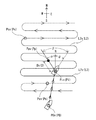
しかしながら、海底調査用の無人航走体のような場合には、図13に示すように、海底地形を線というよりは折り返して蛇行しながら面として調査することが行われている。そのため、上記のような、追尾対象体の動向に対して、常時自船の針路や速力を変更して、略追尾対象体と同様な自船の軌跡を残すような追従制御では、蛇行している追尾対象体を追跡する場合には、自船も蛇行してしまい、著しく無駄な動きをしてしまうという問題がある。 However, in the case of an unmanned aerial vehicle for submarine survey, as shown in FIG. 13, the submarine topography is surveyed as a plane while folding back and meandering rather than as a line. Therefore, in the following tracking control that constantly changes the course and speed of the own ship in response to the movement of the tracking target object and leaves a trajectory of the own ship similar to the tracking target object, it meanders. When tracking a tracking target object, there is a problem that the ship also meanders and makes a useless movement.
本発明は、上記の状況を鑑みてなされたものであり、その目的は、追尾対象体が蛇行するような場合においても、自船の蛇行量を少なくできて、燃費効率が良い状態で、追尾対象体に追従できる船舶の自動操縦システム、船舶、及び船舶の自動操縦方法を提供することにある。 The present invention has been made in view of the above circumstances, and an object thereof is to perform tracking even in a case where the tracking target object is meandering, in which the meandering amount of the own ship can be reduced and the fuel efficiency is good. An object of the present invention is to provide a ship automatic pilot system capable of following an object, a ship, and a ship automatic pilot method.
上記のような目的を達成するための船舶の自動操縦システムは、追尾対象体の動きに従って自船を自動操船する船舶の自動操縦システムにおいて、前記追尾対象体を運用するコースに対応する仮想追尾対象体の仮想コースを前記仮想座標平面上に設けるコース設定手段と、予め設定された前記仮想コースに対しての図形的な第1条件を満たす仮想移動地点を設定する移動地点設定手段と、前記追尾対象体の位置を検出して、前記仮想座標平面上に前記仮想追尾対象体の仮想位置を描き、前記仮想位置が予め設定された前記仮想コースに対しての図形的な第2条件を満たすときを移動開始時点とする移動開始時点算出手段と、この移動開始時点となったときに移動許可信号の入力を得て若しくは移動許可信号の入力を得ることなく、前記仮想移動地点に対応する実際の移動地点に向かって自船を移動する自動操船を行う自動操船手段を有する図形追跡自動操船手段を備えて構成されている。 An automatic pilot system for a ship to achieve the above-mentioned object is a virtual tracking target corresponding to a course in which the tracking target is operated in an automatic pilot system for a ship that automatically steers its own ship according to the movement of the tracking target. Course setting means for providing a virtual course of the body on the virtual coordinate plane, moving point setting means for setting a virtual moving point that satisfies a first graphical condition for the preset virtual course, and the tracking When the position of the target object is detected, the virtual position of the virtual tracking target object is drawn on the virtual coordinate plane, and the virtual position satisfies the second graphical condition for the preset virtual course. At the movement start time point, and when the movement start time point is reached, the virtual movement is performed with or without a movement permission signal input. It is configured to include a graphic tracing automatic maneuvering means having an automatic maneuvering means for performing automatic maneuvering to move the actual ship towards the moving point corresponding to the point.
なお、この追尾対象体には、航走形態を限定せず、浮上航走体や水中航走体などの水上や水中を移動する移動体や船舶等でもよく、無人でも有人でもよい。また、追尾対象体の操縦形態も限定せず、自船が操縦する航走体や、自律して航行するために自船が影響を及ぼすことができない航走体や他の船舶も含む。 It should be noted that the tracking target is not limited to the sailing mode, and may be a moving body such as a floating running body or an underwater running body that moves on or under water, or a ship, and may be unmanned or manned. In addition, the control mode of the tracking target body is not limited, and includes a traveling body operated by the own ship, a traveling body which the own ship cannot influence because it autonomously navigates, and other ships.
なお、ここでは、実際の追尾対象体と自船が航行している実際の水域に対して、パネル表示画面上やレーダー画面上や計算用の座標平面等の実際の水域を投影した座標平面を設けており、この座標平面をここでは仮想座標平面と称している。この仮想座標平面上での、追尾対象体、自船に対応するそれぞれのシンボルを仮想追尾対象体、仮想自船とし、実際の水域における位置や移動地点やコース等に対して、仮想座標平面上では「仮想」を付けて、実際の水域と区別している。 In addition, here, the coordinate plane that projected the actual water area on the panel display screen, the radar screen, the coordinate plane for calculation, etc., with respect to the actual tracking target and the actual water area where the own ship is navigating. This coordinate plane is referred to as a virtual coordinate plane here. On the virtual coordinate plane, the tracking target object and the respective symbols corresponding to the own ship are set as the virtual tracking target object and the virtual own ship, and the position on the actual water area, the moving point, the course, etc. are displayed on the virtual coordinate plane. Then, "virtual" is added to distinguish it from the actual water area.
また、この仮想コースを描き続ける時間は、例えば、予め設定した時間を経過するまでの間、若しくは仮想コースの長さが予め設定された設定長さになるまでの間等であり、仮想コースの移動開始時点になったら算出された移動地点に自船を移動すると共に、次の移動開始時点になるまで同じことを行い、これを、追尾対象体が運用するコースの終了地点に至るまで、繰り返し行う。 Further, the time for continuing to draw this virtual course is, for example, until a preset time elapses, or until the length of the virtual course reaches a preset set length. When the movement start time comes, move the ship to the calculated movement point and do the same until the next movement start time, and repeat this until the end point of the course operated by the tracking target object. To do.
この構成によれば、追尾対象体が蛇行するような場合においても、追尾対象体の位置を検出して、この追尾対象体の仮想位置と仮想コースとの関係を基に、追尾対象体に自船を追従させることで、自船の蛇行量を少なくできて、燃費効率が良い状態で、追尾対象体に追従できる。 According to this configuration, even when the tracking target object meanders, the position of the tracking target object is detected, and the tracking target object is automatically detected based on the relationship between the virtual position of the tracking target object and the virtual course. By following the ship, it is possible to reduce the amount of meandering of the ship and to follow the tracking target object in a state of good fuel efficiency.
上記の船舶の自動操縦システムで、前記移動開始時点算出手段が、前記仮想座標平面上において、前記仮想コースに直交若しくは斜交する仮想クロスラインと、この仮想クロスラインを横切る横切り方向を設定し、前記仮想追尾対象体が前記仮想クロスラインを前記横切り方向に横切った時点を前記移動開始時点とするクロス判定手段を備えて構成されていると、前記仮想コースと交差する仮想クロスラインを横切り方向に横切る時点を基準に移動開始を行うので、前記仮想位置が予め設定された仮想コースに対しての図形的な第2条件を満たす移動開始時点を比較的簡便なアルゴリズムで算出できる。 In the above-described ship automatic control system, the movement start time point calculation means, on the virtual coordinate plane, sets a crossing direction that intersects the virtual crossline orthogonally or obliquely to the virtual course, and the virtual crossline, When the virtual tracking target is configured to include a cross determination unit that sets the time when the virtual crossing line crosses the virtual cross line in the crossing direction as the movement start time, the virtual crossing line that intersects the virtual course is crossed in the crossing direction. Since the movement start is performed on the basis of the time point of crossing, the movement start time point satisfying the graphical second condition for the virtual course in which the virtual position is preset can be calculated by a relatively simple algorithm.
上記の船舶の自動操縦システムにおいて、前記移動開始時点算出手段が、追尾対象体を運用するコースに対応する仮想追尾対象体の仮想コースを前記仮想座標平面上に設けて、この仮想コース上に予めチェック領域を設けて、仮想追尾対象体が前記チェック領域を通過した時点を前記移動開始時点とするチェック領域判定手段を備えて構成されていると、仮想コース上のチェック領域を通過する時点を基準に移動開始を行うので、仮想軌跡が予め設定された仮想コースに対しての図形的な第2条件を満たす移動開始時点を比較的簡便なアルゴリズムで算出できる。 In the above ship automatic pilot system, the movement start time point calculating means provides a virtual course of a virtual tracking target object corresponding to a course operating the tracking target object on the virtual coordinate plane, and preliminarily on this virtual course. When a check area is provided and a check area determination unit that makes the time when the virtual tracking target object passes the check area the movement start time is configured, Since the movement start is performed at, the movement start time point that satisfies the graphical second condition for the virtual course in which the virtual trajectory is set in advance can be calculated with a relatively simple algorithm.
上記の船舶の自動操縦システムにおいて、前記移動開始時点算出手段が、前記仮想座標平面上において、予め等間隔のラインを設定して、前記ラインで囲まれたマス目を設けると共に、前記仮想コース上を進む前記仮想追尾対象体が通過するマス目の数を積算した積算数が予め設定された設定数に達した時点を前記移動開始時点とするグリッド判定手段を備えて構成されていると、仮想追尾対象体が通過するマス目の数を積算して設定数と比較するということで、仮想軌跡が予め設定された仮想コースに対しての図形的な第2条件を満たす移動開始時点を比較的簡便なアルゴリズムで算出できる。 In the above ship automatic control system, the movement start time point calculation means sets lines at equal intervals in advance on the virtual coordinate plane to provide squares surrounded by the lines, and on the virtual course. When the virtual tracking target is configured to include a grid determination unit that sets the time when the integrated number obtained by integrating the number of squares through which the virtual tracking target passes reaches a preset set number as the movement start time, By accumulating the number of squares through which the tracking target object passes and comparing it with the set number, it is possible to relatively set the movement start time point that satisfies the second graphical condition for the virtual course in which the virtual trajectory is preset. It can be calculated with a simple algorithm.
上記の船舶の自動操縦システムにおいて、前記図形追跡自動操船手段が、前記移動開始時点になったときに、自船の移動を促す移動通報を発生し、移動許可信号の入力を得てから前記仮想移動地点に対応する実際の移動地点に向かって自船を移動し、移動許可信号の入力を得るまでは、自船の移動を開始しない制御をする移動待機手段を備えて構成されていると、移動許可信号の入力が操作員による判断で入れたり、入れなかったりすることができるようになるので、より安全に、自船を移動できるようになる。 In the above ship automatic control system, the graphic tracking automatic marine vessel maneuvering device generates a movement report urging the movement of the own vessel when the movement start time is reached, and the virtual movement is performed after the movement permission signal is input. Move the ship toward the actual moving point corresponding to the moving point, and until it receives the input of the movement permission signal, it is configured with a movement waiting means for controlling not to start moving the own vessel, Since it becomes possible for the operator to enter the movement permission signal or not depending on the judgment, it becomes possible to move the own vessel more safely.
上記の船舶の自動操縦システムにおいて、前記図形追跡自動操船手段が、自船を前記仮想移動地点に対応する実際の移動地点に移動してから、次の前記移動開始時点になるまで、自船を予め設定される定位置領域内に位置保持する定位置保持制御を行う定位置保持手段を備えて構成されていると、自船が漂流することなく、追尾対象体のコースに対しての位置関係を保持できる。 In the above ship automatic control system, the figure tracking automatic marine vessel maneuvering device moves the ship to an actual movement point corresponding to the virtual movement point until the next movement start time. If it is configured with a fixed position holding means for performing fixed position holding control for holding the position within a preset fixed position area, the positional relationship of the tracking target object with respect to the course without drifting of the own ship. Can hold.
上記の船舶の自動操縦システムにおいて、前記図形追跡自動操船手段が、前記仮想コースの終点において、仮想終了判定領域を設けて、この仮想終了判定領域に前記仮想追尾対象体の前記仮想位置が入ったときに、制御を終了する終了判定手段を備えて構成されていると、自動的に追尾対象体への追従を終了することができる。この制御終了に際しては、操作員にその旨を知らせる通知をブザーや音声メッセージや画面表示で行うことが好ましい。 In the above ship automatic control system, the figure tracking automatic marine vessel maneuvering device provides a virtual end determination area at the end point of the virtual course, and the virtual position of the virtual tracking target is entered in the virtual end determination area. At this time, if it is configured to include an end determination unit that ends the control, it is possible to automatically end the tracking of the tracking target object. Upon completion of this control, it is preferable to give a notification to the operator by a buzzer, a voice message, or a screen display.
上記の船舶の自動操縦システムにおいて、前記図形追跡自動操船手段が、前記仮想コースの周囲にコース運用領域を設けて、このコース運用領域から前記仮想追尾対象体の前記仮想位置が逸脱した場合に、コース逸脱警報を発生するコース逸脱警報手段を備えて構成されていると、何らかに原因で追尾対象体が運用コースを外れたことを操作員に通知できるので、追尾対象体回収などの事故対策を早期に行うことができるようになる。 In the above ship automatic control system, the figure tracking automatic marine vessel manipulating means provides a course operation area around the virtual course, and when the virtual position of the virtual tracking target deviates from the course operation area, If the system is equipped with a course deviation warning device that issues a course deviation warning, it can notify the operator that the tracking target object has deviated from the operation course due to some reason, so measures against accidents such as collection of tracking target objects can be taken. You will be able to do it early.
上記の船舶の自動操縦システムにおいて、前記図形追跡自動操船手段が、前記仮想コースの上にチェック領域を設けて、このチェック領域を逸脱して航行した場合に、チェック領域逸脱警報を発生するチェック領域逸脱警報手段を備えて構成されていると、何らかに原因で追尾対象体がチェック領域を逸脱して航行したことを操作員に通知できるので、追尾対象体回収などの事故対策を早期に行うことができるようになる。 In the above ship automatic control system, the graphic tracking automatic marine vessel manipulating means provides a check area on the virtual course, and when a vessel departs from the check area, a check area deviation warning is issued. If the system is equipped with deviation warning means, it can notify the operator that the tracking target has deviated from the check area for some reason, and can take countermeasures for accidents such as recovery of the tracking target at an early stage. Will be able to.
前記仮想コースの最初の移動開始時点に対応する仮想追尾対象体の仮想移動開始位置に対して入力された自船の仮想入力位置と、真方位、相対方位若しくは針路を用いて、前記仮想移動開始位置と前記仮想入力位置との間の仮想離間距離を算出し、これらの入力値と算出値を用いて、自船の設定真方位、設定相対方位若しくは針路、設定仮想離間距離と、2番目以降の移動開始時点に対応する自船の仮想入力位置を設定する移動地点設定手段を備えて構成されていると、仮想コースに対しての図形的な第1条件を満たす仮想移動地点の算出及び設定を非常に簡便に行うことができるようになる。 Using the virtual input position of the own ship, which is input with respect to the virtual movement start position of the virtual tracking target object corresponding to the first movement start time of the virtual course, and the true azimuth, the relative azimuth, or the course, the virtual movement start The virtual separation distance between the position and the virtual input position is calculated, and using these input values and calculated values, the set true bearing, set relative bearing or course of the ship, the set virtual separation distance, and the second and subsequent ones. Of the virtual moving point that sets the virtual input position of the own ship corresponding to the moving start time of the virtual course, the calculation and setting of the virtual moving point satisfying the first graphical condition for the virtual course. Can be performed very easily.
そして、上記のような目的を達成するための船舶は、上記の船舶の自動操縦システムを備えていることを特徴とし、上記の船舶の自動操縦システムの効果を発揮できる。 A ship for achieving the above-mentioned object is characterized by being provided with the above-mentioned ship automatic control system, and can exhibit the effects of the above-mentioned ship automatic control system.
上記のような目的を達成するための船舶の自動操縦方法は、追尾対象体の動きに従って自船を自動操船する船舶の自動操縦方法において、前記追尾対象体を運用するコースに対応する仮想追尾対象体の仮想コースを前記仮想座標平面上に設けて、予め設定された前記仮想コースに対しての図形的な第1条件を満たす仮想移動地点を算出する設定ステップと、前記追尾対象体の位置を検出して、前記仮想座標平面上に前記仮想追尾対象体の仮想位置を描く仮想位置表示ステップと、前記仮想位置が予め設定された前記仮想コースに対しての図形的な第2条件を満たすか否かを判定する判定ステップと、前記判定ステップで前記図形的な第2条件を満たす場合に、移動許可信号の入力を得て若しくは移動許可信号の入力を得ることなく、前記仮想移動地点に対応する実際の移動地点に向かって自船を移動するステップとを含むことを特徴とする方法である。 The automatic piloting method for a ship to achieve the above object is an automatic piloting method for a ship that automatically steers its own ship according to the movement of the tracking target object, and is a virtual tracking target corresponding to the course in which the tracking target object is operated. A virtual course of the body is provided on the virtual coordinate plane, and a setting step of calculating a virtual movement point satisfying the first graphical condition for the preset virtual course and a position of the tracking target object are set. A virtual position display step of detecting and drawing a virtual position of the virtual tracking target on the virtual coordinate plane; and whether the virtual position satisfies a second graphical condition for the preset virtual course. A determination step for determining whether or not the virtual second condition is satisfied in the determination step, the virtual Towards the actual movement point corresponding to the moving point is a method characterized by including the step of moving the ship.
この方法によれば、追尾対象体が蛇行するような場合においても、追尾対象体の位置を検出して、この追尾対象体の位置に対応する仮想追尾対象体の仮想位置と仮想コースとの関係を基に、追尾対象体に自船を追従させることで、自船の蛇行量を少なくできて、燃費効率が良い状態で、追尾対象体に追従できる。 According to this method, even when the tracking target is meandering, the position of the tracking target is detected, and the relationship between the virtual position of the virtual tracking target corresponding to the position of the tracking target and the virtual course is detected. Based on the above, by causing the subject ship to follow the tracking target object, the meandering amount of the own ship can be reduced, and the tracking target object can be followed in a fuel-efficient state.
本発明の船舶の自動操縦システム、船舶、及び船舶の自動操縦方法によれば、追尾対象体が蛇行するような場合においても、追尾対象体の位置を検出して、この追尾対象体の位置に対応する仮想追尾対象体の仮想位置と仮想コースとの関係を基に、追尾対象体に自船を追従させることで、自船の蛇行量を少なくできて、燃費効率が良い状態で、追尾対象体に追従できる。 According to the ship automatic control system, the ship, and the ship automatic control method of the present invention, even when the tracking target meanders, the position of the tracking target is detected, and the position of the tracking target is detected. Based on the relationship between the virtual position of the corresponding virtual tracking target and the virtual course, the tracking target can be made to follow the ship, and the meandering amount of the ship can be reduced, and the tracking target can be achieved in a fuel-efficient state. Can follow the body.
以下、本発明に係る実施の形態の船舶の自動操縦システム、船舶、及び船舶の自動操縦方法について、図面を参照しながら説明する。そして、本発明の実施の形態の船舶は、本発明の実施の形態の船舶の自動操縦システムを備えている船舶である。図1に示すように、この船舶の自動操縦システム1は、図形追跡自動操船手段20を備え、図2に示すような制御フローの制御を行う。また、この本発明の船舶は、測量船、海洋調査船、海洋研究船、資源探査船、海底資源探査船、地球深部探査船、海洋地球研究船、ケーブル敷設船等の場合に大きな効果を発揮できるが、これらの船に限定されず、その他の船舶であってもよい。この追尾対象体には、航走形態を限定せず、浮上航走体や水中航走体などの水上や水中を移動する移動体や船舶等でもよく、無人でも有人でもよい。また、追尾対象体の操縦形態も限定せず、自船が操縦する航走体や自律して航行するために自船が影響を及ぼすことができない航走体や他の船舶も含む。
DESCRIPTION OF THE PREFERRED EMBODIMENTS Hereinafter, a ship automatic pilot system, a ship, and a ship automatic pilot method according to embodiments of the present invention will be described with reference to the drawings. Then, the ship according to the embodiment of the present invention is a ship provided with the automatic pilot system for a ship according to the embodiment of the present invention. As shown in FIG. 1, the ship automatic piloting system 1 includes a graphic tracking automatic marine
さらに、ここでは、船舶が2軸2舵の船舶で、かつ、ジョイスティック等で構成される移動情報入力部と、ダイヤル等で構成される旋回情報入力部を有する入力装置を有する船舶の操縦システムを備えている船舶を例にして説明しているが、本発明の船舶は2軸2舵に限定されず、また、入力装置も「ジョイスティックとダイヤル」の入力装置に限定されない。 Further, here, there is provided a ship operation system including a ship having two axes and two rudders, and an input device having a movement information input unit configured by a joystick or the like and a turning information input unit configured by a dial or the like. Although the vessel provided is described as an example, the vessel of the present invention is not limited to the two-axis / two-rudder type, and the input device is not limited to the “joystick and dial” input device.
なお、ここでは、実際の追尾対象体と自船が航行している実際の水域に対して、パネル表示画面上やレーダー画面上や計算用の座標平面等の実際の水域を投影した座標平面を設けており、この座標平面をここでは仮想座標平面と称している。この仮想座標平面上での、追尾対象体2、自船1に対応するそれぞれのシンボルを仮想追尾対象体2v、仮想自船1vとし、実際の水域における位置や移動地点やコース等に対して、仮想座標平面上では「仮想」を付けて、実際の水域と区別している。
In addition, here, the coordinate plane that projected the actual water area on the panel display screen, the radar screen, the coordinate plane for calculation, etc., with respect to the actual tracking target and the actual water area where the own ship is navigating. This coordinate plane is referred to as a virtual coordinate plane here. On the virtual coordinate plane, the respective symbols corresponding to the
つまり、実際の水域の実際の値を表示する場合は、図3に例示するように、それぞれ、コースL2、追尾対象体2の位置Pp、追尾対象体2の開始地点Ps、追尾対象体2の終了地点Pe、自船1の移動地点Piと表示し、仮想座標平面上の値を表示する場合は、それぞれ、仮想コースL2v、仮想追尾対象体2vの仮想位置Ppv、仮想開始地点Psv、仮想終了地点Pev、仮想移動地点Pivと表示する。これにより、コースL2と仮想コースL2v、位置Ppと仮想位置Ppv、開始地点Psの位置と仮想開始地点Psvの位置、終了地点Peの位置と仮想終了地点Pevの位置、移動地点Piの位置と仮想移動地点Pivの位置が、互いに相似の関係となる。
That is, when the actual value of the actual water area is displayed, as illustrated in FIG. 3, the course L2, the position Pp of the
また、「真方位、相対方位、針路」に関しては、図3に例示するように、ここで用いる「真方位」αとは地形に対する方位であり、例えば、東西南北(E−W−N−S)等の方位を言う。また、ここで用いる「相対方位」βとは、自船1から他の位置(例えば仮想図心Pcv)を見たときの自船1から見える自船基準の追尾対象体2の位置Ppの方位のことを言い、例えば、自船1の船首方向を基準(0度)とした方位で、船首(0度)、右正横(90度)、船尾(180度)、左正横(270度)などである。また、針路θとは、地形に対する自船1の船首方向の方位であり、例えば、北(N)に対する方位となる
また、仮想座標平面としては、操作パネル面上や数値計算用の面等の実際の地形図と相似関係にある地形図面等の目視できる図形が好ましいが、必ずしも、目視できるものでなくて、計算上で同じ操作や算出ができれば、目視できる図形を伴っていなくてもよい。その意味でここでは「仮想座標平面」という言い方を採用している。
Further, as for “true bearing, relative bearing, and course”, as illustrated in FIG. 3, the “true bearing” α used here is a bearing with respect to the terrain, for example, east-west north-south (EWN-S). ) Etc. say the direction. In addition, the “relative azimuth” β used here is the azimuth of the position Pp of the
本発明に係る実施の形態の船舶1は、例えば、図4に示すように、船舶の操縦システム100を備えている。この船舶の操縦システム100は、左舷側推進器31aと左舷側舵31bとからなる左舷側推進システム31と、右舷側推進器32aと右舷側舵32bとからなる右舷側推進システム32の2つの推進システム31、32を船尾に備えて構成される。この左舷側推進器31aと右舷側推進器32aの両方を可変プロペラで構成する。このプロペラは固定ピッチプロペラで構成してもよいが、可変ピッチプロペラで構成すると推力の変更が容易となるのでより好ましい。また、特に図示しないが、旋回補助装置として船首スラスターや船尾スラスターを備えていてもよい。 The marine vessel 1 of the embodiment according to the present invention includes a marine vessel maneuvering system 100, for example, as shown in FIG. This vessel control system 100 includes two propulsion systems, a port side propulsion system 31 including a port side propulsion device 31a and a port side rudder 31b, and a starboard side propulsion system 32 including a port side propulsion device 32a and a starboard side rudder 32b. The system is provided with the systems 31 and 32 at the stern. Both the port-side propulsion device 31a and the starboard-side propulsion device 32a are composed of variable propellers. The propeller may be a fixed-pitch propeller, but it is more preferable to use a variable-pitch propeller because the thrust can be easily changed. Although not particularly shown, a bow thruster or a stern thruster may be provided as the turning assist device.
また、入力装置40と操縦制御装置30を備えている。この入力装置40は、ジョイスティック等で構成される移動情報入力部41と、ダイヤル(回頭ダイヤル)等で構成される旋回情報入力部42とを有して構成される。この操縦制御装置30は、移動情報入力部41からの傾倒方向(操船方向:船の移動方向)と、その方向におけるジョイスティックの傾斜角度の大きさの傾斜角度のデータと、旋回情報入力部42からのダイヤルの旋回方向とダイヤル角度を入力する。
Further, the
この操縦制御装置30は、これらのデータの他にも、GPS装置、ログ等からの船舶1の位置情報や速度情報、ジャイロ装置からの船首方位情報や、風向風速計からの情報、水中測位装置からの情報、レーダーからの情報、距離測定装置や測距通信装置などのからの情報などを入力して、左舷側推進器31aと右舷側推進器32aのそれぞれにおける前進又は後進の選択と、発生する推力の大きさの指令とを、それぞれのプロペラの制御装置31ac、32acに出力し、これにより、水流Wを発生し、推力Ta、Tbを得る。また、左舷側舵31bと右舷側舵32bの面舵(船首が右に回転)と取舵(船首が左に回転)の選択と、その舵角の大きさの指令とをそれぞれの舵取装置31bc、32bcに出力する。
In addition to these data, the
つまり、この船舶の操縦システム100では、操作員が、自船1の操船のために入力装置40で移動情報入力部41と旋回情報入力部42を操作すると、操縦制御装置30は、この移動情報入力部41からの傾倒方向と傾斜角度のデータ、及び、旋回情報入力部42からのダイヤルの旋回方向とダイヤル角度のデータを受けて、推進器31a、32aと舵31b、32bを統合制御して、船舶の前進、後進、並進、斜め前並進、斜め後並進、その場回頭など操船を行う。
In other words, in this vessel maneuvering system 100, when the operator operates the movement
そして、本発明においては、この船舶の操縦システム100が本発明に係る実施の形態の船舶の自動操縦システム10を備えて構成される。この船舶の自動操縦システム10は、図1に示すように、図形追跡自動操船手段20を備え、また、この図形追跡自動操船手段20は、コース設定手段21、移動地点設定手段22、移動開始時点算出手段23、自動操船手段24を有している。また、さらに、移動待機手段25、定位置保持手段26、終了判定手段27、コース逸脱警報手段28A、チェック領域逸脱警報手段28B、移動地点設定手段29を備えていることが好ましい。
Further, in the present invention, the ship steering system 100 is configured to include the ship
このコース設定手段21は、追尾対象体2を運用するコースL2に対応する仮想追尾対象体2vの仮想コースL2vを仮想座標平面上に設ける手段である。移動地点設定手段22は、予め設定された仮想コースL2vに対しての図形的な第1条件を満たす仮想移動地点(フォロー点)Pivを設定する手段である。
The course setting means 21 is means for providing the virtual course L2v of the virtual
移動開始時点算出手段23は、追尾対象体2の位置Pvを検出して、この位置Pvに対応する仮想位置Ppvを仮想座標平面上に描き、仮想位置Ppvが予め設定された仮想コースL2vに対しての図形的な第1条件を満たすときを移動開始時点tiとする手段である。この追尾対象体2の位置Ppvを検出する際には、追尾対象体2の位置Ppに関する追尾対象体情報をソナーなどの音響装置の上方や追尾対象体2からの通信による情報などにより得て、この位置Ppを仮想座標平面上に描き、この仮想座標平面上に描かれた仮想追尾対象体2の現時点の位置を仮想追尾対象体2vの仮想位置Ppvとする。
The movement start time point calculation means 23 detects the position Pv of the
また、自動操船手段24は、移動開始時点tiとなったときに移動許可信号の入力を得て若しくは移動許可信号の入力を得ることなく、仮想移動地点Pivに対応する実際の移動地点Piに向かって自船1を移動する自動操船を行う手段である。 Further, the automatic boat maneuvering means 24 moves toward the actual movement point Pi corresponding to the virtual movement point Piv without obtaining the movement permission signal or the movement permission signal at the movement start time ti. It is a means for performing automatic marine vessel maneuvering by moving the own ship 1.
この自動操船における、自船1が移動地点(フォロー点)Pi間を移動する際の船首方位α(またはβ)及び航行速度Vは、予め設定されている方位αs(またはβs)及び速度Vsを維持するように移動するものとし、それら設定方位αs(またはβs)、設定航行速度Vsは移動中においても任意に変更が可能なものとする。なお、各移動地点Pi−1〜Pi間を移動する場合には、通常は、特別な事情が無ければ、自船1は現在の移動地点Pi−1と次の移動地点Piを結ぶ直線上を移動するものとする。しかし、この直線状に障害物がある場合には、迂回するコースに変更できるようにしておくことが好ましい。 In this automatic vessel maneuvering, the heading α (or β) and the navigation speed V when the ship 1 moves between the movement points (following points) Pi are the preset direction αs (or βs) and the speed Vs. It is assumed that the vehicle moves so as to be maintained, and the set azimuth αs (or βs) and the set navigation speed Vs can be arbitrarily changed even during the movement. When moving between the moving points Pi-1 to Pi, the ship 1 normally follows a straight line connecting the current moving point Pi-1 and the next moving point Pi unless there are special circumstances. Shall be moved. However, when there is an obstacle in this straight line, it is preferable to be able to change to a detour course.
より詳細には、移動開始時点tiと移動地点Piを得て、自船1の現在位置Pi−1から移動地点Piに移動するための針路θと航行速度V等を算出する。これらの 針路θ、航行速度V等の自船1の航行用データを入力とし、舵31b、32bの舵角を操作する操舵機の制御データ、船首スラスター、船尾スラスター、プロペラ31a、32a等の推進システム31、32への制御データ等を出力する。 More specifically, the travel start time ti and the travel point Pi are obtained, and the course θ for moving from the current position Pi-1 of the ship 1 to the travel point Pi and the navigation speed V are calculated. Propulsion of steering data, steering thrusters, stern thrusters, propellers 31a, 32a, etc., using the navigation data of the ship 1, such as the course θ and the navigation speed V, as input, and operating the steering angles of the rudders 31b, 32b. It outputs control data and the like to the systems 31 and 32.
この入力の航行用データと制御データの関係は、予め実験や計算などにより、対応マップを作成したり、対応関数を設定したりして、入力データに対して算出値を出力するフィードフォワード制御や、入力の航行用データに対応する計測値を目標値に近づけるフィードバック制御などの周知の制御方法を用いることができる。なお、船首スラスター、船尾スラスターなどを備えている場合には、これらの制御データも出力される。 The relationship between the input navigation data and the control data is based on experiments, calculations, etc. in advance to create a correspondence map or set a correspondence function, and to perform feedforward control that outputs calculated values to the input data. A well-known control method such as feedback control that brings a measured value corresponding to the input navigation data close to a target value can be used. If the bow thruster, the stern thruster, etc. are provided, these control data are also output.
また、制御データに従っての推進システム31、32を駆動して、これにより、自船1を自動操船する。この自動操船により、移動開始時点tiから移動地点Piに向かって移動を開始し、自船1を移動地点Piに移動する。 Further, the propulsion systems 31 and 32 are driven according to the control data, whereby the own ship 1 is automatically operated. By this automatic marine vessel maneuvering, the movement starts from the movement start time ti toward the movement point Pi, and the own ship 1 moves to the movement point Pi.
また、移動待機手段25は、移動開始時点tiになったときに、自船1の移動を促す移動通報を発生し、移動許可信号の入力を得てから仮想移動地点Pivに対応する実際の移動地点Piに向かって自船1を移動し、移動許可信号の入力を得るまでは、自船1の移動を開始しない制御をする手段である。これにより、移動許可信号の入力が操作員による判断で入れたり、入れなかったりすることができるようになるので、より安全に、自船1を移動できるようになる。 Further, the movement waiting means 25, when the movement start time point ti comes, generates a movement notification prompting the movement of the ship 1, and after receiving the input of the movement permission signal, the actual movement corresponding to the virtual movement point Piv. This is a means for controlling the ship 1 not to start moving until the ship 1 is moved toward the point Pi and a movement permission signal is input. As a result, the movement permission signal can be input or not depending on the judgment of the operator, so that the own ship 1 can be moved more safely.
言い換えれば、移動待機手段25は、仮想追尾対象体2vがクロスポイントPciを通過した場合には、自船1の移動地点Piへの変更を推奨する運用警報を発令し、操作員によって次の移動地点Piへの移動が承認されてから自船1は移動を開始するものとする。この場合は、この移動待機手段25により、操作員が次の移動地点Piへの移動を承認しない場合には、仮想追尾対象体2vがクロスポイントPciを通過したとしても自船1は現時点の位置である移動地点Pi−1から移動を開始しないものとする。
In other words, when the
また、定位置保持手段26は、自船1を仮想移動地点Pivに対応する実際の移動地点Piに移動してから、次の移動開始時点ti+1になるまで、自船1を予め設定される定位置領域内に位置保持する定位置保持制御を行う手段である。つまり、自船1が移動地点Piに到達した後は、次の移動開始時点ti+1になるまでは、その地点Piにて占位し続けるように定点保持制御を行う。これにより、自船1が漂流することなく、追尾対象体2のコースL2に対しての位置関係を保持できる。
Further, the fixed position holding means 26 moves the ship 1 to the actual moving point Pi corresponding to the virtual moving point Piv and then sets the ship 1 in advance until the next movement start time ti + 1. It is a means for performing fixed position holding control for holding the position in the position area. That is, after the own ship 1 reaches the movement point Pi, the fixed point holding control is performed so as to continue to be occupied at the point Pi until the next movement start time point ti + 1. As a result, the positional relationship of the
また、終了判定手段27は、図12に示すように、仮想コースL2vの仮想終了地点Pevにおいて、例えば、仮想終了地点Pevを中心とし半径devの円Cevの仮想終了判定領域Pervを設けて、この仮想終了判定領域Pervに仮想追尾対象体2vが入ったときに、制御を終了する手段である。これにより、自動的に追尾対象体2への追従を終了することができる。この制御終了に際しては、操作員にその旨を知らせる通知をブザーや音声メッセージや画面表示で行うことが好ましい。
Further, as shown in FIG. 12, the end determination means 27 provides a virtual end determination area Perv of a circle Cev having a radius dev with a center at the virtual end point Pev at the virtual end point Pev of the virtual course L2v. It is a means for ending the control when the virtual
言い換えれば、仮想コースL2vの仮想終了地点Pevに仮想追尾対象体2vが到達するのを判定する場合においては、ある一定半径devの仮想終了判定領域Pervを設定し、仮想追尾対象体2vがこの仮想終了判定領域Pervに入った時点で終了点Peに近接したと判定する。また、新たな仮想移動地点群Piv(i=1〜I)に関しては、この終了点近接判定結果に基づいて操作員が改めて設定を行うことになる。
In other words, when it is determined that the
また、コース逸脱警報手段28Aは、仮想コースL2vの周囲にコース運用領域R1を設けて、このコース運用領域R1から仮想追尾対象体2vが逸脱した場合に、コース逸脱警報を発生する手段である。つまり、仮想追尾対象体2vの位置がこの航路幅Bcのコース運用領域R1を逸脱した場合には、コース逸脱の運用警報を発令し、操作員に対する注意喚起を行う。これにより、何らかに原因で追尾対象体2が運用コースL2を外れたことを操作員に通知できるので、追尾対象体2を回収するなどの事故対策を早期に行うことができるようになる。なお、仮想追尾対象体コースに対しては予めコース逸脱警報判定用の航路幅Bcを設定することが出来るものとする。
The course
また、チェック領域逸脱警報手段28Bは、仮想コースL2vの上にチェック領域R2を設けて、このチェック領域R2を逸脱して航行した場合に、チェック領域逸脱警報を発生する手段である。これにより、何らかに原因で追尾対象体がチェック領域を逸脱して航行したことを操作員に通知できるので、追尾対象体2を回収するなどの事故対策を早期に行うことができるようになる。
The check area deviation warning means 28B is a means for providing a check area R2 on the virtual course L2v and for issuing a check area deviation warning when the passenger departs from the check area R2. As a result, the operator can be notified that the tracking target has deviated from the check area for some reason, so that it is possible to take an accident countermeasure such as collecting the
移動地点設定手段29は、図3に示すように、仮想コースL2vの最初の移動開始時点tiに対応する仮想追尾対象体2vの仮想移動開始位置Pc1に対して入力された自船1の仮想入力位置Pinvと、真方位α、相対方位β若しくは針路θを用いて、仮想移動開始位置Pc1と仮想入力位置Pinvとの間の仮想離間距離Dvを算出し、これらの入力値と算出値を用いて、自船1の設定真方位αs、設定相対方位βs若しくは針路θs、設定仮想離間距離Dvsと、2番目以降の移動開始時点Pc2に対応する自船1の仮想入力位置Pinvを設定する手段である。これにより、仮想コースL2vに対しての図形的な第2条件を満たす仮想移動地点Pivの算出及び設定を非常に簡便に行うことができるようになる。
As shown in FIG. 3, the movement point setting means 29 is a virtual input of the own ship 1 input to the virtual movement start position Pc1 of the
また、その他にも、仮想移動地点Ptvと仮想コースL2vとの相対位置を、真方位αが予め設定した設定真方位αsになり、かつ、互いの仮想離間距離Dvが、予め設定された設定離間距離Dsに対応する設定仮想離間距離Dsvになるようにしてもよい。 In addition, in addition, the relative position between the virtual moving point Ptv and the virtual course L2v becomes the set true direction αs in which the true azimuth α is set in advance, and the virtual separation distance Dv between them is set in the set separation set in advance. The set virtual separation distance Dsv corresponding to the distance Ds may be set.
さらには、母船となる自船1と追尾対象体2との通信などの関係で、追尾対象体2と自船1との相対方位βをある程度の範囲内(β1<β<β2)に抑える必要がある場合などでは、追尾対象体2と自船1との相対方位βがその範囲内(β1<β<β2)になるように自船1の針路θを設定したり、自船1の針路θを予め設定された設定針路θsに設定したりすることができるようにすることが好ましい。
Further, due to the communication between the own ship 1 which is the mother ship and the
あるいは、仮想座標平面上において、移動開始時点ts(計算時点:仮想計算地点Pev)対して予め設定された位置を仮想移動地点Pivとするように構成してもよい。この場合は、操作盤上の選択スイッチやタッチパネル上の選択スイッチなどによって、この予め設定された仮想移動地点Pisを使用することが選択され、さらに、幾つかの図形の第2条件によって予め設定された幾つかの仮想移動地点Pisの中から使用する仮想移動地点Piuを選択する。また、必要に応じて、設定相対変位βsをゼロ又は予め設定された値とするか、若しくは、設定針路θsをゼロ又は予め設定された値とする。その後は、移動開始時点tiにおける仮想追尾対象体2vの位置に対する仮想移動地点Piuの図形的な第1条件を維持した位置をその移動開始時点tiに対応する仮想移動地点Pivとし、この仮想移動地点Pivに対応する実際の移動地点Piを算出する。
Alternatively, on the virtual coordinate plane, a position preset with respect to the movement start time ts (calculation time: virtual calculation point Pev) may be set as the virtual movement point Piv. In this case, using the preset virtual movement point Pis is selected by the selection switch on the operation panel or the selection switch on the touch panel, and further set by the second condition of some figures. The virtual moving point Piu to be used is selected from among several virtual moving points Pis. Further, if necessary, the set relative displacement βs is set to zero or a preset value, or the set course θs is set to zero or a preset value. After that, a position that maintains the graphical first condition of the virtual movement point Piu with respect to the position of the
また、移動開始時点tiにおける仮想追尾対象体2vの仮想位置Ppvが図示された仮想座標平面上において、入力された仮想入力位置Pinvを基準として、仮想コースL2vから見た仮想入力位置Pinvの真方位α、相対方位β若しくは針路θ、仮想位置Ppvと仮想入力位置Pinvとの間の仮想離間距離Dvを、設定真方位αs、設定相対方位βs若しくは設定針路θs、設定仮想離間距離Dsvとして設定する手段を備えて構成してもよい。
In addition, the virtual position Ppv of the
あるいは、設定真方位αs、設定相対方位βs若しくは設定針路θs、設定仮想離間距離Dsvを、入力された値αin、βin若しくはθin、Dinとする手段を備えて構成してもよい。この場合は、操作盤上の選択スイッチやタッチパネル上の選択スイッチなどによって、この手段を使用することが選択されると、その後は、真方位αin、相対方位βin若しくは針路θin、離間距離Dinを入力できるようにして、この入力された値αin、βin若しくはθin、θin、Dinをそれぞれの設定値αs、βs若しくはθs、Dsとして設定する。 Alternatively, the set true direction αs, the set relative direction βs or the set course θs, and the set virtual separation distance Dsv may be provided with a unit for setting the input values αin, βin or θin, Din. In this case, if the use of this means is selected by the selection switch on the operation panel or the selection switch on the touch panel, then the true azimuth αin, the relative azimuth βin or the course θin, and the separation distance Din are input. As possible, the input values αin, βin or θin, θin, Din are set as the respective set values αs, βs or θs, Ds.
そして、移動開始時点算出手段23は、クロス判定手段23aと、チェック領域判定手段23bと、グリッド判定手段23cのいずれか一つ、又は、2つの組み合わせ、又は全部を有して構成される。 Then, the movement start time point calculation means 23 is configured to include any one of the cross determination means 23a, the check area determination means 23b, and the grid determination means 23c, or a combination of the two or all of them.
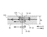
先ず、クロス判定手段23aは、図5に示すように、仮想座標平面上において、仮想コースL2vに直交若しくは斜交する仮想クロスラインL2cと、この仮想クロスラインL2cを横切る横切り方向を設定し、仮想追尾対象体2vの仮想位置Ppvが仮想クロスラインL4vを横切り方向(A方向)に横切った時点を移動開始時点tiとする。そして、このときの情報を基に自船1が占位する移動地点Piに対応する仮想移動地点Pivを設定し、更新する。
First, as shown in FIG. 5, the cross determination means 23a sets a virtual cross line L2c that intersects the virtual course L2v orthogonally or obliquely to the virtual course L2v and a transverse direction that crosses the virtual cross line L2c, as shown in FIG. The time when the virtual position Ppv of the
つまり、追尾対象体2を運用するコースL2に対応する仮想追尾対象体2vの仮想コース(実線で表示)L2vを仮想座標平面上に作成する。この仮想コースL2vに対して、追尾対象体2が観測任務を遂行するにあたり、コースL2上にてどの程度までその任務が進捗しているかを把握するために、この仮想コースL2vに直交又は交差する仮想クロスラインL2c(点線で表示)L2cを作成する。この仮想クロスラインL2cは、仮想コースL2vと複数個所で交差するように設定される直線や曲線で構成されるが、直線とすることが制御が単純化するのでより好ましく、その始点Pcs及び終点Pceは任意に設定される。
That is, a virtual course (displayed by a solid line) L2v of the
この仮想クロスラインL2cと仮想コースL2vとの交点をクロスポイントPci(i=1〜6)と称する。このクロスポイントPciを仮想追尾対象体2vが通過するごとに1→2→3・・・とカウントする。各クロスポイントPciにおいては、仮想コースL2v上の仮想追尾対象体2vの進行方向に応じて、仮想クロスラインL2cを横切る方向を識別する。より具体的には、例えば、図5に示すように、仮想コースL2vに対し、進行方向を左方向(A方向)とする。
The intersection of the virtual cross line L2c and the virtual course L2v is called a cross point Pci (i = 1 to 6). Each time the
なお、図5及び図6において、Psは運用開始時の初期仮想移動地点(初期フォロー点)を示し、これに対して各点Piは、追尾対象体2の各クロスポイントPciの通過を認識して自船1を移動させるべき仮想移動地点Pivを示す。この仮想移動地点Pivの位置は、追尾対象体2の各クロスポイントPciの通過に応じた位置を、任意に設定できるものとする。例えば、図6では各クロスポイントPciに対する仮想移動地点Piv(i=1〜6)を直線上に設定した例を示しているが、必ずしも全ての仮想移動地点Piv(i=1〜6)を直線上に設定する必要は無い。
5 and 6, Ps indicates an initial virtual moving point (initial follow point) at the time of starting operation, whereas each point Pi recognizes passage of each cross point Pci of the
また、クロス判定手段23aでは、図7に示すように、仮想コースL2vのラインを中心に一定の幅(コース幅。操作員による手動設定が可能)Bcを持たせ、この幅Bcの中のコース運用領域R1で、予め自動設定された横切り方向Aを仮想追尾対象体2vが通過した場合に、当該クロスポイントPciを通過したと認定するものとする。しかし、図7に示す、追尾対象体2v(a)のようにコース運用領域R1内を通過する場合は通過とするが、追尾対象体2v(b)のようなコース運用領域R1の外の航行は非通過とし、追尾対象体2v(c)のような逆行は非通過とする。これにより、隣接のコースL2の航路との干渉等による誤認識を防ぐ。なお、コース逸脱警報手段28Aにより、仮想コースL2vの周囲に設けたコース運用領域R1から仮想追尾対象体2vが逸脱した場合に、コース逸脱警報を発生することが好ましい。
Further, as shown in FIG. 7, the cross determination means 23a has a certain width (course width, which can be manually set by an operator) Bc around the line of the virtual course L2v, and the course within this width Bc In the operation area R1, when the
次に、チェック領域判定手段23bについて説明する。このチェック領域判定手段23bは、図9に示すように、仮想座標平面上に追尾対象体2を運用するコースL2に対応する仮想追尾対象体2vの仮想コースL2vを設けて、この仮想コースL2v上に予めチェック領域Priを設けて、仮想追尾対象体2vがこのチェック領域Priを通過した時点を移動開始時点tiとする。そして、このときの情報を基に自船1が占位する移動地点Piに対応する仮想移動地点Pivを設定し、更新する。
Next, the check
つまり、図9に示すように、追尾対象体2を運用するコースL2に対応する仮想追尾対象体2vの仮想コース(実線で表示)L2vを仮想座標平面上に作成する。この仮想コースL2vに対して、追尾対象体2が観測任務を遂行するにあたり、コースL2上にてどの程度までその任務が進捗しているかを把握するために、この仮想コースL2vにチェック領域(チェックポイント:1点鎖線で表示)Priを作成する。このチェック領域Priは、例えば、図8に示すように、仮想コースL2v上の任意の地点Pcriに複数(図8では12か所に)設定される。その始点Pr1及び終点Pr12は任意に設定される。このチェック領域Priを仮想追尾対象体2vが通過するごとに1→2→3・・・とカウントする。
That is, as shown in FIG. 9, a virtual course (displayed by a solid line) L2v of the
各チェック領域Pri(i=12)においては、予め設定された半径drとチェックポイントPcriによりチェック領域Priを形成する通過判定円Crを設定する。図9に示すように、追尾対象体2v(a)がこの通過判定円Crの内部を通過する場合を、当該チェック領域Priを通過したと認定する。また、追尾対象体2v(b)のようにこの通過判定円Crの外部を通過した場合には、当該チェック領域Priを通過していないと認定する。
In each check area Pri (i = 12), a passage determination circle Cr that forms the check area Pri is set by the preset radius dr and the check point Pcri. As shown in FIG. 9, when the
なお、仮想追尾対象体2v(c)がチェック領域Priを通過したと認定されていないにも関わらず、当該チェック領域Pri以降の仮想コースL2vを航走していると判定された場合には、運用警報を発令し、操作員に対する注意喚起を行う。この運用警報を確認した後、操作員の指示入力によって次の移動地点Piへの移動を開始することが出来るものとする。
In addition, when it is determined that the
次に、グリッド判定手段23cについて説明する。図10及び図11に示すように、このグリッド判定手段23cでは、仮想座標平面上に予め等間隔のラインであるグリッド(格子:点線で表示)を設定して、このラインで囲まれたマス目を設けると共に、追尾対象体2を運用するコースL2に対応する仮想追尾対象体2vの仮想コース(実線で表示)L2vを設けて、この仮想コースL2v上を進む仮想追尾対象体2vが通過するマス目の数を積算し、このマス目の積算数Nmが予め設定された設定数Ncに達した時点を移動開始時点tiとする。そして、このときの情報を基に自船1が占位する移動地点Piに対応する仮想移動地点Pivを設定し、更新する。
Next, the grid determination means 23c will be described. As shown in FIGS. 10 and 11, the grid determination means 23c sets grids (lattices: indicated by dotted lines) that are lines at equal intervals in advance on the virtual coordinate plane, and the grids surrounded by the lines are set. And a virtual course (displayed by a solid line) L2v of the
つまり、追尾対象体2を運用するコースL2に対応する仮想追尾対象体2vの仮想コースL2vを仮想座標平面上に作成する。この仮想コースL2vに対して、追尾対象体2が観測任務を遂行するにあたり、コースL2上にてどの程度までその任務が進捗しているかを把握するために、設定運用コースエリアとしてのグリッドエリア(格子領域)Rgを作成する。このグリッドエリアRgは、東西方向をY軸、南北方向をX軸とし、グリッドの相互距離Dgは航行速度Vや風速や潮流の速度等のパラメータにより設定することが好ましく、操作員が操作することなく、製造・調整段階での設定しておくことが好ましい。そして、仮想追尾対象体2vの仮想コースL2vが設定されると同時に、設定運用コースエリアRgが自動的に認識され、システム上にて設定されるように構成する。
That is, the virtual course L2v of the
この設定運用コースエリアRgに対し、追尾対象体2が航走したコースL2に該当する仮想座標平面上の仮想コースL2vを航走する仮想追尾対象体2vが通過し他マス目の数を積算し、その積算値Nmを算出する。この積算値Nmが設定値Ncを超えるか否かを判定し、積算値Nmが設定値Ncを超えたときを移動開始時点tiとする。この設定値Ncは、操作員により予め設定されるものとする。
For this set operation course area Rg, the virtual
このマス目に関する設定値Ncは、追尾対象体2がカバーする観測エリアの全体に対する割合、言い換えれば、追尾対象体2の運用のコースL2(仮想追尾対象体2vの仮想コースL2v)における航走率に関係する値であり、この割合を常時算出して、設定した割合(航走率)に応じて、移動地点Piを順次変更、設定するものである。つまり、仮想コースL2v全体のます目数Nmaxを航走率100%とし、移動開始時点算出用の判定用航走率(例えば10%等)ηとするときに、設定値Ncを「Nc=(η/100)×Nmax)」とする。
The set value Nc related to the square is a ratio of the entire observation area covered by the
なお、このマス目の数の積算値(航走率)は、追尾対象体2が実際に航走したエリアでカウントするのではなく、あくまで仮想コースL2vにおける仮想追尾対象体2vの仮想位置Ppvに基づいて算出する。つまり、実際の追尾対象体2の位置が運用コースL2からずれている場合には、実際の追尾対象体2の位置Ppを仮想座標平面上に投影した仮想位置Ppvを基にマス目の数の積算値の算出を行う。
It should be noted that the integrated value (running rate) of the number of squares is not counted in the area where the
この構成によれば、追尾対象体2が蛇行するような場合においても、追尾対象体2の位置Ppを検出して、この追尾対象体2の位置Ppに対応する仮想追尾対象体2vの仮想位置Ppvと仮想コースL2vとの関係を基に、追尾対象体2に自船1を追従させることで、自船1の蛇行量を少なくできて、燃費効率が良い状態で、追尾対象体2に追従できる。
According to this configuration, even when the
なお、自動操船システムの図形追跡自動操船手段20で自動操船する図形追跡自動操船モードで自動操船中に、旋回情報入力部42のダイヤルが操作員によって操作されるなどの、予め設定された中断用操作がなされたことを検出した場合には、図形追跡自動操船モードを自動的に手動により操船をする手動操船モードに切り替えることが好ましい。この手動操船モードでは、例えば、自船1のプロペラ回転数若しくは可変ピッチプロペラのピッチ角度や舵角を、移動情報入力部41のジョイスティックの傾斜方向と傾斜角度、旋回情報入力部42のダイヤルの回転量などの操作量に従って操作し、これにより、自船1の針路と航行速度などが制御される。
It should be noted that for preset interruptions such as the dial of the turning
また、再度、図形追跡自動操船モードに戻る場合には、自動的に再び図形追跡自動操船モードに移行させずに、改めて、図形追跡自動操船モードを選択した場合に、戻るように構成される。 Further, when returning to the figure tracking automatic marine vessel maneuvering mode again, it is configured to return to the case where the figure tracking automatic marine vessel maneuvering mode is selected again without automatically shifting to the figure tracking automatic marine vessel maneuvering mode again.
次に、本発明に係る実施の形態の船舶の自動操縦方法について、図2の制御フローを参照しながら説明する。この船舶の自動操縦方法は、追尾対象体2の動きに従って自船1を自動操船する船舶の自動操縦方法において、追尾対象体2を運用するコースL2に対応する仮想追尾対象体2vの仮想コースL2vを仮想座標平面上に設けて、予め設定された仮想コースL2vに対しての図形的な第1条件を満たす仮想移動地点Pivを算出する設定ステップと、追尾対象体2の位置Ppを検出して、この位置Ppに対応する仮想位置Ppvを仮想座標平面上に描く仮想位置表示ステップと、仮想位置Ppvが予め設定された仮想コースL2vに対しての図形的な第2条件を満たすか否かを判定する判定ステップと、この判定ステップで前記図形的な第2条件を満たす場合に、移動許可信号の入力を得て若しくは移動許可信号の入力を得ることなく、仮想移動地点Pivに対応する実際の移動地点Piに向かって自船を移動するステップとを含む方法である。
Next, an automatic ship steering method according to an embodiment of the present invention will be described with reference to the control flow of FIG. In this ship automatic control method, the virtual course L2v of the
この船舶の自動操縦方法は、図2に例示するような制御フローによって実施できる。この図2の制御フローは、本発明に係る実施の形態の船舶(自船)1の操船の開始と共に、上級の制御フローから呼ばれてスタートし、自船1の操船の終了と共に、上級の制御フローに戻り、上級の制御フローと共に終了するものとして示してある。 This ship automatic control method can be implemented by the control flow illustrated in FIG. The control flow of FIG. 2 is called from the advanced control flow when the operation of the ship (own ship) 1 according to the embodiment of the present invention is started, and starts, and when the operation of the own ship 1 ends, the control flow of the advanced ship It is shown as returning to the control flow and ending with the advanced control flow.
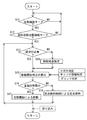
自船1の操船が開始されると、図2の制御フローがスタートし、ステップS11で、自動操縦装置による自動操船モードが要求されているか否かを、操船用スイッチや操船用のタッチパネルなどにより判定する。このステップS11で自動操船モードが選択されていなければ(NO)、予め設定された時間を経過した後にステップS11に戻る。また、ステップS11で自動操船モードが選択されていれば(YES)、ステップS12に行き、図形追跡自動操船モードが選択されているかを判定する。 When the operation of the own ship 1 is started, the control flow of FIG. 2 is started, and in step S11, whether or not the automatic operation mode by the automatic control device is requested is determined by the operation switch, the operation touch panel, or the like. judge. If the automatic marine vessel maneuvering mode has not been selected in step S11 (NO), the process returns to step S11 after a preset time has elapsed. If the automatic marine vessel maneuvering mode is selected in step S11 (YES), the process proceeds to step S12, and it is determined whether the figure tracking automatic marine vessel maneuvering mode is selected.
このステップS11とステップS12は同時に行うことが好ましい。つまり、図形追跡自動操船モードの選択のみで自動的に自動操船モードが選択されると判定できるようにすることで、図形追跡自動操船モードへの移行を円滑に行えるようにする。 It is preferable that step S11 and step S12 be performed at the same time. That is, it is possible to smoothly shift to the figure tracking automatic marine vessel maneuvering mode by making it possible to determine that the automatic marine vessel maneuvering mode is automatically selected only by selecting the figure pursuit automatic marine vessel maneuvering mode.
ステップS12で図形追跡自動操船モードが選択されていなければ(NO)、予め設定された時間を経過した後にステップS11に戻る。また、ステップS12で図形追跡自動操船モードが選択されば(YES)、ステップS13に行く。 If the figure tracking automatic marine vessel maneuvering mode is not selected in step S12 (NO), the process returns to step S11 after a preset time has elapsed. If the figure tracking automatic marine vessel maneuvering mode is selected in step S12 (YES), the process proceeds to step S13.
次のステップS13では、仮想移動地点Pivを設定するための設定真方位αs、設定相対方位βs若しくは設定針路θsと設定仮想離間距離Dsv若しくは設定離間距離Dsを設定するか否かをチェックし、これらを設定するのであれば(YES)、ステップS14に行く。ステップS14の移動地点設定で、移動地点設定手段22で各種の設定値を設定する。 In the next step S13, it is checked whether or not the set true azimuth αs, the set relative azimuth βs, or the set course θs and the set virtual separation distance Dsv or the set separation distance Ds for setting the virtual movement point Piv are set. If is set (YES), go to step S14. In the moving point setting in step S14, the moving point setting means 22 sets various setting values.
ステップS13で移動地点設定を行う必要が無い場合は(NO)、ステップS15の移動開始時点の算出を行う。このステップS15では、移動開始時点算出手段23のうちの3つのクロス判定手段23a、チェック領域判定手段23b、グリッド判定手段23cのいずれかを選択して、それぞれの手段によって移動開始時点tiを算出する。 If it is not necessary to set the movement point in step S13 (NO), the movement start time is calculated in step S15. In this step S15, one of the three cross determination means 23a, the check area determination means 23b, and the grid determination means 23c of the movement start time point calculation means 23 is selected, and the movement start time point ti is calculated by each of them. .
この移動開始時点tiの算出では,追尾対象体2の位置Pvを、レーダーやソナーなどにより得て、これらの追尾対象体2の自船1に対する位置情報から、自船1の針路θの変化分や位置移動分を補正することにより、自船1との相対位置関係だけでなく、絶対座標(地形に固定の座標)での位置関係としての位置Pvを得ることができ、この追尾対象体2の位置Pvを仮想座標平面上に仮想追尾対象体2vの仮想位置Ppvとして表示する。なお、この移動開始時点の算出では、コース逸脱警報手段28A若しくはチェック領域逸脱警報手段28Bにより、追尾対象体2の動きを監視し、必要に応じて警報を発生する。また、終了判定手段27により、仮想追尾対象体2の位置Ppvが仮想終了判定領域に入ったときは、割り込みに行き、この図2の制御フローを終了する。この制御終了に際しては、操作員にその旨を知らせる通知をブザーや音声メッセージや画面表示で行うことが好ましい。
In the calculation of the movement start time point ti, the position Pv of the
そして、ステップS16で、移動開始時点tiが算出された自船1を移動するか否かを判定する。この判定で、移動開始時点tiとなっていれば、ステップS17の自動操船による移動に行く。また、移動開始時点tiとなっていければ、ステップS18の定点保持制御による定点保持に行く。 Then, in step S16, it is determined whether or not to move the ship 1 for which the movement start time ti has been calculated. In this determination, if the movement start time point ti is reached, the movement proceeds to automatic marine vessel maneuvering in step S17. If the movement start time ti has come, the fixed point holding control of step S18 is performed.
ステップS17の自動操船による移動では、移動開始時点tiが自動操船手段24に出力されると、移動開始時点tiと移動地点Piに基づいて、移動地点Piに移動するための、自船1の航行で必要な自船情報を算出する。つまり、自船1の現在地点Pi−1から移動地点Piに移動するための針路θと航行速度Vなどを算出する。特別な事情が無ければ、通常は直線的に移動地点Piに向かうが、回避する場所や追尾対象体がある場合には、その回避を行う航路とこの航路を航行するための情報を算出する。この移動に際しては、移動待機手段25により待機する必要がある場合には移動開始の指示を待ってから、移動を開始する。 In the movement by the automatic marine vessel maneuvering in step S17, when the movement start time point ti is output to the automatic marine vessel maneuvering means 24, the navigation of the own ship 1 for moving to the movement point Pi based on the movement start time point ti and the movement point Pi. Calculate necessary ship information in. That is, the course θ for moving from the current point Pi-1 of the own ship 1 to the movement point Pi and the navigation speed V are calculated. If there is no special circumstance, it usually goes straight to the moving point Pi, but if there is a place to avoid or a tracking target object, the route to avoid and the information for navigating this route are calculated. In this movement, if it is necessary to wait by the movement waiting means 25, the movement is started after waiting an instruction to start the movement.
そして、航行用の自船情報から、舵や船首スラスターや船尾スラスターや推進装置等の具体的な装置を制御する操船情報を算出する。この航行用の自船情報から操船情報を算出する方法は、周知のフィードフォワード法やフィードバック法などの制御アルゴリズムを用いることができる。そして、ステップS17の自動操船による移動で、自船1が移動地点に到達すると、ステップS13に戻る。 Then, from the own-ship information for navigation, ship maneuvering information for controlling specific devices such as a rudder, a bow thruster, a stern thruster, and a propulsion device is calculated. A known control algorithm such as a feedforward method or a feedback method can be used as a method of calculating the marine vessel maneuvering information from the own ship information for navigation. Then, when the own ship 1 reaches the movement point by the movement by the automatic marine vessel maneuvering in step S17, the process returns to step S13.
一方、ステップS17では、定点保持制御による定点保持を予め設定された制御時間お間行って、ステップS13に戻る。この定点保持は、移動地点Piを中心とする定点保持制御であり、周知の定点保持制御の技術で行われる。そして、この定点保持制御は、S16のステップで移動開始時点の算出で、移動開始時点ti+1になるまで行われる。言い換えれば、ステップS16の自動操船による移動を行っていないときは定点保持を行う。 On the other hand, in step S17, fixed point holding by fixed point holding control is performed for a preset control time, and the process returns to step S13. This fixed point holding is a fixed point holding control centered on the moving point Pi, and is performed by a known fixed point holding control technique. Then, the fixed point holding control is performed until the movement start time point ti + 1 is calculated by calculating the movement start time point in step S16. In other words, the fixed point is maintained when the automatic marine vessel maneuvering in step S16 is not performed.
なお、終了判定手段27による制御の終了、又は、何らかの都合で、この図形追跡自走操船モードが終了になるときは、割り込みにより、図2の制御フローを中断して、リターンに行き、上級の制御フローに戻る。そして、必要に応じて、上級の制御フローの終了と共に、図2の制御フローも終了する。 Note that when the figure tracking self-propelled marine vessel maneuvering mode ends due to the end of the control by the end determination means 27 or for some reason, the control flow of FIG. Return to control flow. Then, if necessary, the control flow of FIG. 2 is ended together with the end of the advanced control flow.
そして、本発明の実施の形態の船舶1は、上記の船舶の自動操縦システム10を備えて構成される。従って、この船舶1は、上記の船舶の自動操縦システム10を使用して自動操船できるので、この船舶の自動操縦システム10で可能な船舶の自動操船方法を実施できる。
The ship 1 according to the embodiment of the present invention is configured to include the above-described ship
従って、上記の船舶の自動操縦システム10、船舶1、及び船舶の自動操縦方法によれば、追尾対象体2が蛇行するような場合においても、追尾対象体2の位置Ppを検出して、この追尾対象体2の位置Ppに対応する仮想追尾対象体2vの仮想位置Ppvと仮想コースL2vとの関係を基に、追尾対象体2に自船1を追従させることで、自船1の蛇行量を少なくできて、燃費効率が良い状態で、追尾対象体2に追従できる。
Therefore, according to the ship
1 自船
2 追尾対象体
2v 仮想追尾対象体
10 船舶の自動操縦システム
20 図形追跡自動操船手段
21 コース設定手段
22 移動地点設定手段
23 移動開始時点算出手段
23a クロス判定手段
23b チェック領域判定手段
23c グリッド判定手段
24 自動操船手段
25 移動待機手段
26 定位置保持手段
27 終了判定手段
28A コース逸脱警報手段
28B チェック領域逸脱警報手段
29 移動地点設定手段
30 操縦制御装置
31a 左舷側推進器
31b 左舷側舵
31 左舷側推進システム(推進システム)
32a 右舷側推進器
32b 右舷側舵
32 右舷側推進システム(推進システム)
40 入力装置
41 移動情報入力部
42 旋回情報入力部
α 真方位
β 相対方位
θ 針路
Dv 仮想離間距離
L2 追尾対象体の運用コース
L2v 仮想コース
Pp 追尾対象体の位置
Ppv 仮想追尾対象体の仮想位置
1
32a Starboard side propeller 32b Starboard side rudder 32 Starboard side propulsion system (propulsion system)
40
Claims (12)
前記追尾対象体を運用するコースに対応する仮想追尾対象体の仮想コースを前記仮想座標平面上に設けるコース設定手段と、
予め設定された前記仮想コースに対しての図形的な第1条件を満たす仮想移動地点を設定する移動地点設定手段と、
前記追尾対象体の位置を検出して、前記仮想座標平面上に前記仮想追尾対象体の仮想位置を描き、前記仮想位置が予め設定された前記仮想コースに対しての図形的な第2条件を満たすときを移動開始時点とする移動開始時点算出手段と、
この移動開始時点となったときに移動許可信号の入力を得て若しくは移動許可信号の入力を得ることなく、前記仮想移動地点に対応する実際の移動地点に向かって自船を移動する自動操船を行う自動操船手段を有する図形追跡自動操船手段を備えて構成されていることを特徴とする船舶の自動操縦システム。 In an autopilot system for a ship that automatically steers its own ship according to the movement of the tracking target,
Course setting means for providing a virtual course of a virtual tracking target corresponding to a course operating the tracking target on the virtual coordinate plane,
Moving point setting means for setting a virtual moving point that satisfies a first graphical condition for the preset virtual course;
The position of the tracking target object is detected, the virtual position of the virtual tracking target object is drawn on the virtual coordinate plane, and the virtual second condition is set in advance for the virtual course in which the virtual position is preset. A movement start time point calculation means having a movement start time point when the condition is satisfied,
When the movement start time comes, an automatic marine vessel maneuvering to move the ship toward an actual movement point corresponding to the virtual movement point without obtaining a movement permission signal or without a movement permission signal. An automatic piloting system for a ship, comprising: a graphic tracking automatic marine vessel manipulating means having an automatic marine vessel maneuvering means.
前記仮想追尾対象体が前記仮想クロスラインを前記横切り方向に横切った時点を前記移動開始時点とするクロス判定手段を備えて構成されていることを特徴とする請求項1に記載の船舶の自動操縦システム。 The movement start time point calculating means, on the virtual coordinate plane, sets a virtual cross line orthogonal or oblique to the virtual course, and a crossing direction crossing the virtual cross line,
The automatic piloting of a marine vessel according to claim 1, further comprising a cross determination unit that sets the movement start time to a time point when the virtual tracking target object crosses the virtual cross line in the crossing direction. system.
仮想追尾対象体が前記チェック領域を通過した時点を前記移動開始時点とするチェック領域判定手段を備えて構成されていることを特徴とする請求項1または2に記載の船舶の自動操縦システム。 The movement start time point calculation means provides a virtual course of a virtual tracking target object corresponding to a course operating the tracking target object on the virtual coordinate plane, and previously provides a check area on the virtual course,
The ship automatic control system according to claim 1 or 2, further comprising: a check area determination unit that sets the time when the virtual tracking target passes the check area as the movement start time.
前記追尾対象体を運用するコースに対応する仮想追尾対象体の仮想コースを前記仮想座標平面上に設けて、予め設定された前記仮想コースに対しての図形的な第1条件を満たす仮想移動地点を算出する設定ステップと、
前記追尾対象体の位置を検出して、前記仮想座標平面上に前記仮想追尾対象体の仮想位置を描く仮想位置表示ステップと、
前記仮想位置が予め設定された前記仮想コースに対しての図形的な第2条件を満たすか否かを判定する判定ステップと、
前記判定ステップで前記図形的な第2条件を満たす場合に、移動許可信号の入力を得て若しくは移動許可信号の入力を得ることなく、前記仮想移動地点に対応する実際の移動地点に向かって自船を移動するステップとを含むことを特徴とする船舶の自動操縦方法。 In the automatic piloting method of a ship that automatically steers its own ship according to the movement of the tracking target object,
A virtual movement point where a virtual course of a virtual tracking target corresponding to a course in which the tracking target is operated is provided on the virtual coordinate plane to satisfy a first graphical condition for the preset virtual course. A setting step to calculate
A virtual position display step of detecting the position of the tracking target object and drawing a virtual position of the virtual tracking target object on the virtual coordinate plane,
A determination step of determining whether or not the virtual position satisfies a graphical second condition for the preset virtual course;
When the graphically second condition is satisfied in the determination step, the vehicle automatically moves toward the actual movement point corresponding to the virtual movement point without obtaining a movement permission signal or without a movement permission signal. And a step of moving the ship.
Priority Applications (2)
| Application Number | Priority Date | Filing Date | Title |
|---|---|---|---|
| JP2016255455A JP6686249B2 (en) | 2016-12-28 | 2016-12-28 | Ship automatic control system, ship, and automatic ship control method |
| PCT/JP2017/046384 WO2018123948A1 (en) | 2016-12-28 | 2017-12-25 | Autopilot system for vessel, vessel, and autopilot method for vessel |
Applications Claiming Priority (1)
| Application Number | Priority Date | Filing Date | Title |
|---|---|---|---|
| JP2016255455A JP6686249B2 (en) | 2016-12-28 | 2016-12-28 | Ship automatic control system, ship, and automatic ship control method |
Publications (2)
| Publication Number | Publication Date |
|---|---|
| JP2018103950A JP2018103950A (en) | 2018-07-05 |
| JP6686249B2 true JP6686249B2 (en) | 2020-04-22 |
Family
ID=62707552
Family Applications (1)
| Application Number | Title | Priority Date | Filing Date |
|---|---|---|---|
| JP2016255455A Active JP6686249B2 (en) | 2016-12-28 | 2016-12-28 | Ship automatic control system, ship, and automatic ship control method |
Country Status (2)
| Country | Link |
|---|---|
| JP (1) | JP6686249B2 (en) |
| WO (1) | WO2018123948A1 (en) |
Families Citing this family (4)
| Publication number | Priority date | Publication date | Assignee | Title |
|---|---|---|---|---|
| US11181916B2 (en) | 2020-03-20 | 2021-11-23 | Yamaha Hatsudoki Kabushiki Kaisha | Watercraft and watercraft control system |
| US11334079B2 (en) | 2020-03-26 | 2022-05-17 | Yamaha Hatsudoki Kabushiki Kaisha | Watercraft and watercraft control system |
| CN115277533B (en) * | 2022-07-20 | 2023-11-03 | 内蒙古电力(集团)有限责任公司内蒙古电力科学研究院分公司 | Automatic drawing method for static physical link topology of transformer substation |
| CN116245916B (en) * | 2023-05-11 | 2023-07-28 | 中国人民解放军国防科技大学 | Unmanned ship-oriented infrared ship target tracking method and device |
Family Cites Families (4)
| Publication number | Priority date | Publication date | Assignee | Title |
|---|---|---|---|---|
| JPH08249060A (en) * | 1995-03-15 | 1996-09-27 | Yokogawa Denshi Kiki Kk | Autonomous submerged sailing device |
| JP2009132257A (en) * | 2007-11-30 | 2009-06-18 | Universal Shipbuilding Corp | Method, program, and device for maneuvering control, and automatic maneuvering control system |
| JP5566426B2 (en) * | 2012-07-04 | 2014-08-06 | ジャパンマリンユナイテッド株式会社 | Ship maneuvering control apparatus, automatic ship maneuvering control system, ship maneuvering control method, and program |
| JP5442071B2 (en) * | 2012-07-04 | 2014-03-12 | ジャパンマリンユナイテッド株式会社 | Ship maneuvering control apparatus, automatic ship maneuvering control system, ship maneuvering control method, and program |
-
2016
- 2016-12-28 JP JP2016255455A patent/JP6686249B2/en active Active
-
2017
- 2017-12-25 WO PCT/JP2017/046384 patent/WO2018123948A1/en active Application Filing
Also Published As
| Publication number | Publication date |
|---|---|
| WO2018123948A1 (en) | 2018-07-05 |
| JP2018103950A (en) | 2018-07-05 |
Similar Documents
| Publication | Publication Date | Title |
|---|---|---|
| JP6336162B2 (en) | Improved ship maneuvering method and system | |
| EP1365301B1 (en) | Method and system for maneuvering a movable object | |
| JP6686249B2 (en) | Ship automatic control system, ship, and automatic ship control method | |
| CN102999050B (en) | Automatic obstacle avoidance method for intelligent underwater robots | |
| CN109960262B (en) | Unmanned ship dynamic obstacle avoidance method and system based on geometric method | |
| US11373537B2 (en) | Marine propulsion control system and method with collision avoidance override | |
| US11600184B2 (en) | Marine propulsion control system and method | |
| WO2021230356A1 (en) | Method for autonomously guiding vessel, program for autonomously guiding vessel, system for autonomously guiding vessel, and vessel | |
| CN113759939B (en) | Intelligent navigation method and device for limited water area | |
| US10460484B2 (en) | Systems and associated methods for route generation and modification | |
| WO2018123947A1 (en) | Autopilot system for vessel, vessel, and autopilot method for vessel | |
| JP5932362B2 (en) | Hull Control Device, Hull Control Program, and Hull Control Method | |
| US11702178B2 (en) | Marine propulsion control system, method, and user interface for marine vessel docking and launch | |
| JP2012203682A (en) | Display method of on-board control device for underwater sailing body | |
| JP6773874B2 (en) | Propulsion control systems and methods for ships with speed limits based on proximity | |
| KR20170064345A (en) | Autonomous navigation system for a sailing yacht and method thereof | |
| JP2001287697A (en) | Ship course holding control device and method | |
| Jo et al. | Development of autonomous algorithm for boat using robot operating system | |
| Paez et al. | Implementation of an unmanned surface vehicle for environmental monitoring applications | |
| CN116974282A (en) | Unmanned ship-based marine search area coverage path planning method | |
| Yan et al. | An Obstacle Avoidance Algorithm for Unmanned Surface Vehicle Based on A Star and Velocity-Obstacle Algorithms | |
| Mahipala et al. | Model Predictive Control for Path Following and Collision-Avoidance of Autonomous Ships in Inland Waterways | |
| CN112034866B (en) | Method and device for tracking and guiding underwater robot | |
| JP6658220B2 (en) | Navigation control method and device | |
| WO2020111044A1 (en) | Control target generation device and ship-steering control device |
Legal Events
| Date | Code | Title | Description |
|---|---|---|---|
| A711 | Notification of change in applicant |
Free format text: JAPANESE INTERMEDIATE CODE: A712 Effective date: 20180604 |
|
| A625 | Written request for application examination (by other person) |
Free format text: JAPANESE INTERMEDIATE CODE: A625 Effective date: 20190313 |
|
| TRDD | Decision of grant or rejection written | ||
| A01 | Written decision to grant a patent or to grant a registration (utility model) |
Free format text: JAPANESE INTERMEDIATE CODE: A01 Effective date: 20200303 |
|
| A61 | First payment of annual fees (during grant procedure) |
Free format text: JAPANESE INTERMEDIATE CODE: A61 Effective date: 20200305 |
|
| R150 | Certificate of patent or registration of utility model |
Ref document number: 6686249 Country of ref document: JP Free format text: JAPANESE INTERMEDIATE CODE: R150 |
|
| S111 | Request for change of ownership or part of ownership |
Free format text: JAPANESE INTERMEDIATE CODE: R313111 |
|
| R350 | Written notification of registration of transfer |
Free format text: JAPANESE INTERMEDIATE CODE: R350 |
|
| R250 | Receipt of annual fees |
Free format text: JAPANESE INTERMEDIATE CODE: R250 |
|
| R250 | Receipt of annual fees |
Free format text: JAPANESE INTERMEDIATE CODE: R250 |