JP6685992B2 - Absorbent article - Google Patents
Absorbent article Download PDFInfo
- Publication number
- JP6685992B2 JP6685992B2 JP2017254061A JP2017254061A JP6685992B2 JP 6685992 B2 JP6685992 B2 JP 6685992B2 JP 2017254061 A JP2017254061 A JP 2017254061A JP 2017254061 A JP2017254061 A JP 2017254061A JP 6685992 B2 JP6685992 B2 JP 6685992B2
- Authority
- JP
- Japan
- Prior art keywords
- topsheet
- surface sheet
- absorbent article
- sheet
- free end
- Prior art date
- Legal status (The legal status is an assumption and is not a legal conclusion. Google has not performed a legal analysis and makes no representation as to the accuracy of the status listed.)
- Active
Links
- 230000002745 absorbent Effects 0.000 title claims description 77
- 239000002250 absorbent Substances 0.000 title claims description 77
- 239000000835 fiber Substances 0.000 claims description 21
- 239000000853 adhesive Substances 0.000 claims description 13
- 230000001070 adhesive effect Effects 0.000 claims description 13
- 230000006835 compression Effects 0.000 description 19
- 238000007906 compression Methods 0.000 description 19
- 229920000742 Cotton Polymers 0.000 description 11
- 239000004745 nonwoven fabric Substances 0.000 description 9
- 239000000463 material Substances 0.000 description 5
- 210000001124 body fluid Anatomy 0.000 description 3
- 239000010839 body fluid Substances 0.000 description 3
- 238000002788 crimping Methods 0.000 description 3
- 239000007788 liquid Substances 0.000 description 3
- -1 polyethylene Polymers 0.000 description 2
- 239000011347 resin Substances 0.000 description 2
- 229920005989 resin Polymers 0.000 description 2
- 238000007789 sealing Methods 0.000 description 2
- 229920000247 superabsorbent polymer Polymers 0.000 description 2
- 206010021639 Incontinence Diseases 0.000 description 1
- 239000004698 Polyethylene Substances 0.000 description 1
- 239000004743 Polypropylene Substances 0.000 description 1
- 230000003187 abdominal effect Effects 0.000 description 1
- 238000010521 absorption reaction Methods 0.000 description 1
- 210000001217 buttock Anatomy 0.000 description 1
- 230000002550 fecal effect Effects 0.000 description 1
- 230000004927 fusion Effects 0.000 description 1
- 210000004251 human milk Anatomy 0.000 description 1
- 235000020256 human milk Nutrition 0.000 description 1
- 238000005259 measurement Methods 0.000 description 1
- 230000002093 peripheral effect Effects 0.000 description 1
- 229920000573 polyethylene Polymers 0.000 description 1
- 229920001155 polypropylene Polymers 0.000 description 1
- 230000002040 relaxant effect Effects 0.000 description 1
- 210000004243 sweat Anatomy 0.000 description 1
Images


Description
本発明は、生理用ナプキン等の吸収性物品に関する。 The present invention relates to absorbent articles such as sanitary napkins.
特許文献1には、生理用ナプキン等の吸収性物品が開示されている。特許文献1の吸収性物品は、吸収コアの肌対向面側に複数の表面シートが設けられている。表面シートは、第1表面シート(特許文献1の表面シート)と、第1表面シートと厚さ方向に重なる第2表面シート(特許文献1の熱融着性繊維シート)と、を有する。第1表面シートは、非熱融着繊維を含むコットン不織布によって構成されている。また、第1表面シートと第2表面シートには、厚さ方向に圧縮された圧搾部が形成されている。 Patent Document 1 discloses an absorbent article such as a sanitary napkin. In the absorbent article of Patent Document 1, a plurality of surface sheets are provided on the skin facing surface side of the absorbent core. The topsheet has a first topsheet (topsheet of Patent Document 1) and a second topsheet (heat-fusible fiber sheet of Patent Literature 1) that overlaps the first topsheet in the thickness direction. The first topsheet is made of a cotton non-woven fabric containing non-heat-bonded fibers. In addition, the first surface sheet and the second surface sheet are formed with compressed portions compressed in the thickness direction.
一般的にコットン不織布は、非熱融着繊維の交絡によって形成されている。熱等の融着又は接着剤などによる接着によって繊維同士を結合させた不織布と比較して、引っ張り方向の力が作用した際に裂け易い。よって、コットン不織布からなる第1表面シートと第2表面シートを厚さ方向に圧縮すると、第1表面シートが裂けるおそれがあった。 Generally, a cotton nonwoven fabric is formed by entanglement of non-heat-bonded fibers. Compared to a non-woven fabric in which fibers are bonded together by fusion such as heat or adhesion with an adhesive or the like, it is easy to tear when a force in the tensile direction acts. Therefore, if the first surface sheet and the second surface sheet made of the cotton nonwoven fabric are compressed in the thickness direction, the first surface sheet may be torn.
したがって、非熱融着繊維を含む表面シートに圧搾部を形成した吸収性物品において、表面シートの破れを抑制できる吸収性物品が望まれる。 Therefore, in the absorbent article in which the compressed portion is formed on the surface sheet containing the non-heat-bonding fibers, an absorbent article that can suppress the breakage of the surface sheet is desired.
一態様に係る吸収性物品は、前後方向と、前記前後方向に直交する幅方向と、表面シートと、前記表面シートの非肌対向面側に配置された吸収コアと、を有する吸収性物品であって、表面シートは、非熱融着繊維を含む第1表面シートと、前記第1表面シートの非肌対向面側に位置する第2表面シートと、を有し、少なくとも前記第1表面シートと前記第2表面シートを厚さ方向に圧縮した圧搾部が形成されている吸収性物品であって、前記第1表面シートの外縁には、前記第2表面シートと接合されていない自由端部が設けられている。 The absorbent article according to one aspect is an absorbent article having a front-rear direction, a width direction orthogonal to the front-rear direction, a surface sheet, and an absorbent core arranged on the non-skin facing surface side of the surface sheet. There, the topsheet has a first topsheet containing non-heat-bonding fibers, and a second topsheet located on the non-skin facing side of the first topsheet, and at least the first topsheet And an absorbent article in which a compressed portion obtained by compressing the second surface sheet in the thickness direction is formed, wherein the outer edge of the first surface sheet is a free end portion not joined to the second surface sheet. Is provided.
(1)実施形態の概要
本明細書及び添付図面の記載により、少なくとも以下の事項が明らかとなる。
一態様に係る吸収性物品は、前後方向と、前記前後方向に直交する幅方向と、表面シートと、前記表面シートの非肌対向面側に配置された吸収コアと、を有する吸収性物品であって、表面シートは、非熱融着繊維を含む第1表面シートと、前記第1表面シートの非肌対向面側に位置する第2表面シートと、を有し、少なくとも前記第1表面シートと前記第2表面シートを厚さ方向に圧縮した圧搾部が形成されている吸収性物品であって、前記第1表面シートの外縁には、前記第2表面シートと接合されていない自由端部が設けられている。
(1) Outline of Embodiments At least the following matters will be made clear by the present specification and the description of the accompanying drawings.
The absorbent article according to one aspect is an absorbent article having a front-rear direction, a width direction orthogonal to the front-rear direction, a surface sheet, and an absorbent core arranged on the non-skin facing surface side of the surface sheet. There, the topsheet has a first topsheet containing non-heat-bonding fibers, and a second topsheet located on the non-skin facing side of the first topsheet, and at least the first topsheet And an absorbent article in which a compressed portion obtained by compressing the second surface sheet in the thickness direction is formed, wherein the outer edge of the first surface sheet is a free end portion not joined to the second surface sheet. Is provided.
第1表面シートの自由端部は、平面方向に対して移動し易く、圧搾部の形成時に厚さ方向に圧縮された際に圧搾部側に移動できる。よって、圧搾部の形成時に第1表面シートに係る引っ張り方向の力を低減し、第1表面シートが裂けることを抑制できる。 The free end portion of the first surface sheet is easy to move in the plane direction and can move to the compressed portion side when compressed in the thickness direction when forming the compressed portion. Therefore, it is possible to reduce the force of the first surface sheet in the pulling direction when forming the compressed portion, and to prevent the first surface sheet from tearing.
好ましい一態様によれば、前記圧搾部は、前記第1表面シート、前記第2表面シート及び前記吸収コアが圧縮されている。 According to a preferred aspect, in the compression unit, the first surface sheet, the second surface sheet, and the absorbent core are compressed.
第1表面シート、第2表面シート及び吸収コアが圧縮されている構成にあっては、第1表面シート及び第2表面シートのみが圧縮された構成と比較して圧縮の程度が強く、より第1表面シートがより裂け易い。そのため、自由端部によって第1表面シートの破れを抑制することが好ましい。 In the configuration in which the first topsheet, the second topsheet and the absorbent core are compressed, the degree of compression is higher than in the configuration in which only the first topsheet and the second topsheet are compressed, and 1 The surface sheet is easier to tear. Therefore, it is preferable to prevent the first surface sheet from being broken by the free end portion.
好ましい一態様によれば、前記自由端部は、厚さ方向において前記吸収コアに重なっている。 According to a preferred aspect, the free end overlaps the absorbent core in the thickness direction.
吸収コアに圧搾部が形成され、吸収コアに自由端部が重なっているため、圧搾部と自由端部が近くに配置され易い。引っ張り方向の力を緩和するための自由端部が圧搾部の近くに配置されることにより、第1表面シートが裂けることをより抑制できる。 Since the compressed portion is formed on the absorbent core and the free end portion overlaps with the absorbent core, the compressed portion and the free end portion are easily arranged close to each other. By disposing the free end portion for relieving the force in the pulling direction near the compression portion, it is possible to further prevent the first surface sheet from tearing.
好ましい一態様によれば、前記自由端部は、前記第1表面シートの前記幅方向の外側縁を含み、前記前後方向に延びている。 According to a preferred aspect, the free end portion includes the outer edge in the width direction of the first surface sheet and extends in the front-rear direction.
第1表面シートの外側縁に自由端部を設けることにより、自由端部の面積を確保し易く、第1表面シートの破れをより抑制できる。 By providing the free end portion on the outer edge of the first surface sheet, it is easy to secure the area of the free end portion, and the breakage of the first surface sheet can be further suppressed.
好ましい一態様によれば、前記圧搾部は、第1表面シート側から前記第2表面シート側に向かって凹んでいる。 According to a preferred aspect, the compressed portion is recessed from the first surface sheet side toward the second surface sheet side.
圧搾部によって圧縮する力は、第1表面シートから第2表面シート側にかかる。力が加わる側(肌対向面側)に自由端部が設けられているため、引っ張り方向の力をより緩和でき、第1表面シートの破れをより抑制できる。 The force of compression by the compression unit is applied from the first surface sheet to the second surface sheet side. Since the free end portion is provided on the side to which the force is applied (skin-facing surface side), the force in the pulling direction can be further alleviated and the first surface sheet can be further prevented from breaking.
好ましい一態様によれば、前記第2表面シートの伸度は、前記第1表面シートの伸度よりも高い。 According to a preferred aspect, the elongation of the second topsheet is higher than the elongation of the first topsheet.
第2表面シートは第1表面シートの伸度よりも高いため、第1表面シートに低い伸度のシートを使用し、接合した場合にも、表面シート全体の伸度の低下を抑制、第1表面シートの破れを軽減できる。 Since the second topsheet has a higher elongation than that of the first topsheet, even when a sheet having a low elongation is used as the first topsheet and the two topsheets are joined together, a decrease in the total elongation of the topsheet is suppressed. It is possible to reduce the breakage of the surface sheet.
好ましい一態様によれば、前記第1表面シートと前記第2表面シートを接着する接着剤を有する接着領域が、自由端部よりも内側に設けられており、前記接着領域は、間隔を空けて複数設けられている。 According to a preferred aspect, an adhesive area having an adhesive for adhering the first surface sheet and the second surface sheet is provided inside the free end portion, and the adhesive area is spaced. There are multiple.
接着領域では、第1表面シートと第2表面シートが接合され、接着領域間の領域では、第1表面シートと第2表面シートが接合されていない。そのため、引っ張られる力がかかった際に移動し易い部分(接着領域間の領域)と、移動し難い部分(接着領域)と、が存在する。引っ張られる力がかかった際には、移動し難い部分を基点に移動し易い部分が移動する。当該領域が複数設けられることにより、第1表面シート11の広い範囲で引っ張り方向の力をより緩和でき、第1表面シートの破れをより抑制できる。
In the bonding area, the first surface sheet and the second surface sheet are bonded, and in the area between the bonding areas, the first surface sheet and the second surface sheet are not bonded. Therefore, there are a portion that easily moves when a pulling force is applied (area between the bonding areas) and a portion that does not easily move (bonding area). When a pulling force is applied, a part that is difficult to move moves as a base point and a part that is easy to move moves. By providing a plurality of the regions, the force in the pulling direction can be further alleviated in a wide range of the
好ましい一態様によれば、前記圧搾部は、前記自由端部に配置された第1圧搾部を有する。 According to a preferred aspect, the squeezing section has a first squeezing section arranged at the free end.
第1圧搾部を自由端部に形成する場合は、第1表面シートと第2表面シートが接合されていない領域を圧縮し、第1圧搾部を形成する。少なくとも第1圧搾部の周囲において第1表面シートと第2表面シートが接合されていないため、第1表面シートに作用する引っ張り方向の力を緩和できる。よって、第1表面シートが裂けることをより抑制できる。 When forming the 1st pressing part in a free end, the 1st pressing part is formed by compressing the field where the 1st surface sheet and the 2nd surface sheet are not joined. Since the first surface sheet and the second surface sheet are not joined at least around the first squeezing portion, the pulling force acting on the first surface sheet can be relaxed. Therefore, tearing of the first surface sheet can be further suppressed.
好ましい一態様によれば、前記第1圧搾部は、前記自由端部と、前記第1表面シートよりも外側の領域と、に跨がっている。 According to a preferred aspect, the first compressed portion straddles the free end portion and a region outside the first surface sheet.
第1圧搾部全域が第1表面シートに形成されている構成と比較して、第1圧搾部の形成時に第1表面シートに作用する引っ張り方向の力が緩和される。よって、第1表面シートが裂けることをより抑制できる。 Compared to the configuration in which the entire first compressed portion is formed on the first surface sheet, the pulling force acting on the first surface sheet when forming the first compressed portion is relaxed. Therefore, tearing of the first surface sheet can be further suppressed.
好ましい一態様によれば、前記圧搾部は、平面視にて間隔を空けて一対で配置されており、前記一対の圧搾部同士の間隔は、一定でない。 According to a preferred aspect, the compression units are arranged in a pair with an interval in plan view, and the interval between the pair of compression units is not constant.
圧搾部同士の間隔が広い部分では、当該部分における第1表面シートの長さが長いため、圧搾部の形成時の引っ張り方向の力が弱く作用する。一方、圧搾部同士の間隔が狭い部分では、当該部分における第1表面シートの長さが短いため、圧搾部の形成時の引っ張り方向の力が強く作用する。引っ張り力が強く作用する部分と弱く作用する部分が混在するため、力が均一にかかる場合と比較して力が集中せず、第1表面シートが裂けることをより抑制できる。 Since the length of the first surface sheet in the portion where the interval between the compressed portions is wide is long, the force in the pulling direction when forming the compressed portion acts weakly. On the other hand, in the portion where the interval between the compressed portions is narrow, the length of the first topsheet in that portion is short, so the force in the pulling direction when forming the compressed portion strongly acts. Since the portion where the tensile force acts strongly and the portion where the tensile force acts weakly coexist, the force is not concentrated as compared with the case where the force is uniformly applied, and it is possible to further suppress the tearing of the first surface sheet.
(2)吸収性物品の構成
以下、図面を参照して、実施形態に係る吸収性物品ついて説明する。吸収性物品は、生理用ナプキン、パンティライナー、母乳パッド、大人用失禁パッド、糞便パッド又は汗取りシートのような吸収性物品であってよい。特に、吸収性物品は、使用者の下着のような着用物品の内側に取り付けられて使用される物品であってよい。
(2) Configuration of Absorbent Article Hereinafter, the absorbent article according to the embodiment will be described with reference to the drawings. The absorbent article may be an absorbent article such as a sanitary napkin, a panty liner, a breast milk pad, an adult incontinence pad, a fecal pad or a sweat removal sheet. In particular, the absorbent article may be an article that is attached and used inside a worn article, such as a user's underwear.
なお、以下の図面の記載において、同一又は類似の部分には、同一又は類似の符号を付している。ただし、図面は模式的なものであり、各寸法の比率等は現実のものとは異なる場合があることに留意すべきである。したがって、具体的な寸法等は、以下の説明を参酌して判断すべきである。また、図面相互間においても互いの寸法の関係や比率が異なる部分が含まれる場合がある。 In the following description of the drawings, the same or similar parts are denoted by the same or similar reference numerals. However, it should be noted that the drawings are schematic and the ratios of the respective dimensions may be different from the actual ones. Therefore, specific dimensions should be determined in consideration of the following description. In addition, there may be a case where the drawings have parts where the dimensional relationships and ratios are different from each other.
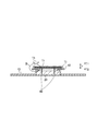
図1は、肌対向面側から見た第1実施形態に係る吸収性物品1の平面図である。ここで、「肌対向面側」は、使用中に着用者の肌に面する側に相当する。「非肌対向面側」は、使用中に着用者の肌とは反対に向けられる側に相当する。図2は、図1に示すA−A線に沿った断面図であり、図3は、図2に示すB部分の拡大図である。 FIG. 1 is a plan view of the absorbent article 1 according to the first embodiment viewed from the skin facing surface side. Here, the “skin facing surface side” corresponds to the side facing the wearer's skin during use. The "non-skin facing side" corresponds to the side facing away from the wearer's skin during use. 2 is a cross-sectional view taken along the line AA shown in FIG. 1, and FIG. 3 is an enlarged view of a portion B shown in FIG.
吸収性物品1は、前後方向L及び幅方向Wを有する。前後方向Lは、着用者の前側(腹側)から後側(背側)に延びる方向、又は着用者の後側から前側に延びる方向である。幅方向Wは、前後方向Lと直交する方向である。 The absorbent article 1 has a front-back direction L and a width direction W. The front-rear direction L is a direction extending from the front side (abdominal side) of the wearer to the rear side (back side), or a direction extending from the rear side of the wearer to the front side. The width direction W is a direction orthogonal to the front-rear direction L.
吸収性物品1は、前側域R1と、後側域R2と、中央域R3と、を含む。中央域R3は、着用者の排泄口(例えば膣口)に対向する排泄口当接部R33を含む。吸収性物品1が下着に装着されたときに、中央域R3は、下着の股下部に位置する。つまり、排泄口当接部R33は、着用者の股下、すなわち着用者の両足の間に配置される領域である。 The absorbent article 1 includes a front region R1, a rear region R2, and a central region R3. The central region R3 includes an excretory opening contact portion R33 that faces the excretory opening (eg, vaginal opening) of the wearer. When the absorbent article 1 is worn on the underwear, the central region R3 is located at the crotch portion of the underwear. That is, the excretory opening contact portion R33 is a region that is arranged between the wearer's crotch, that is, between the wearer's both feet.
前側域R1は、中央域R3よりも前側に位置する。前側域R1の前端縁は、吸収性物品1の前端縁を規定する。後側域R2は、中央域R3よりも後側に位置する。後側域R2の後端縁は、吸収性物品1の後端縁を規定する。後側域R2の前後方向Lの長さは、中央域R3の前後方向Lの長さよりも長くなっていてよい。 The front area R1 is located on the front side of the central area R3. The front edge of the front region R1 defines the front edge of the absorbent article 1. The rear area R2 is located rearward of the central area R3. The rear edge of the rear region R2 defines the rear edge of the absorbent article 1. The length of the rear side region R2 in the front-rear direction L may be longer than the length of the central region R3 in the front-rear direction L.
中央域R3には、後述するウイング3が設けられていてよい。また、後側域R2には、幅方向Wの外側に膨らんだヒップフラップ4が設けられていてよい。ウイング3の前端縁は、ウイング3の付け根によって規定されており、最も幅方向Wの内側に窪んだ2つの部分のうち、前側に位置する部分に相当する。ウイング3の前端縁は、中央域R3と前側域R1との境界を規定していてもよい。ウイング3の後端縁は、ウイング3の付け根によって規定されており、最も幅方向Wの内側に窪んだ2つの部分のうち、後側に位置する部分に相当する。ウイング3の後端縁は、中央域R3と後側域R2との境界を規定していてもよい。
The wing 3 mentioned later may be provided in the central region R3. Further, the rear side region R2 may be provided with a
吸収性物品1は、着用者の肌に向けられる表面シート10と、着用者の肌とは反対側に向けられる裏面シート14と、表面シート10と裏面シート14の間に配置された吸収コア20と、を含む。表面シート10は、吸収コア20よりも肌対向面側T1に設けられる。裏面シート14は、吸収コア20よりも非肌対向面側T2に設けられる。吸収コア20は、表面シート10と裏面シート14との間に設けられる。
The absorbent article 1 includes a
表面シート10は、体液等の液体を透過する液透過性のシートである。表面シート10は、幅方向Wにおける吸収コア20の中央部を覆ってよい。表面シート10は、前側域R1から後側域R2まで前後方向Lに延びていてよい。表面シート10は、第1表面シート11と第1表面シート11の非肌対向面側に位置する第2表面シート12を有してよい。
The
第1表面シート11は、非熱融着繊維を含む。非熱融着繊維は、コットン繊維を例示できる。第1表面シート11は、非熱融着繊維の交絡によって形成されている。コットン繊維の繊維径は、0.9-1.2Dtexであってよく、コットン繊維の繊維長は、25.4-29.4mmであってよい。第1表面シート11は、コットン不織布を例示できる。コットン不織布は、の目付は、30g/m2であってよい。また、第1表面シート11は、2層構造であってもよい。より詳細には、コットン繊維100%の上層と、コットン繊維60%と熱融着性繊維40%の下層と、の積層シートによって構成されてよい。第1表面シート11の破断伸度は、繊維の配向方向に沿った強度が30〜60N/25mmであってよく、繊維の配向方向と直交方向の強度が5〜10N/25mmであってよい。また、第1表面シート11は、図2のように、肌対向面側に凸状のたくれを形成するように形成してもよい。たくれ部を形成することにより、伸度が低い第1表面シートの幅方向に対する伸度を凸形状分増加することが出来るために第1表面シートの破れを軽減できる。
The
第2表面シート12は、熱融着繊維を含む。第2表面シート12は、熱融着繊維の融着によって形成されている。表面シート10は、サイドシート13を更に有してもよい。サイドシート13は、第1表面シート11及び第2表面シート12の幅方向の外側に延びてよい。サイドシート13は、第1表面シート11及び第2表面シート12の非肌対向面側に配置されており、第1表面シート11及び第2表面シート12を覆っていない。
The
図3に示すように、第1表面シート11と第2表面シート12は、厚さ方向Tに積層されている。第1表面シート11と第2表面シート12は、接合領域RXにおいて接合されてよい。第1表面シート11と第2表面シート12が重なる領域には、第1表面シート11と第2表面シート12が接合された接合領域RXと、第1表面シート11と第2表面シート12が接合されていない非接合領域RYと、が設けられる。非接合領域RYの少なくとも一部は、後述する自由端部15を構成する。
As shown in FIG. 3, the
第1表面シート11と第2表面シート12には、圧搾部60が形成されてよい。圧搾部60は、少なくとも第1表面シート11と第2表面シート12を厚さ方向に圧縮している。圧搾部60は、第1表面シート11、第2表面シート12、及び吸収コア20を厚さ方向に圧縮してもよい。本実施の形態の圧搾部60は、第1表面シート11、第2表面シート12、及び吸収コア20を厚さ方向に圧縮している。また、吸収性物品1は、圧搾部60とは別に、第1表面シート11と第2表面シート12を圧着したシート圧着部18を更に備えてもよい。
The
裏面シート14は、液不透過性のシートである。裏面シート14は、ポリエチレンシート、ポリプロピレン等を主体としたラミネート不織布、通気性の樹脂フィルム、スパンボンド、又はスパンレース等の不織布に通気性の樹脂フィルムが接合されたシートなどを用いることができる。 The back sheet 14 is a liquid impermeable sheet. As the back sheet 14, a polyethylene sheet, a laminated non-woven fabric mainly composed of polypropylene, a breathable resin film, a sheet in which a breathable resin film is bonded to a non-woven fabric such as spunbond or spunlace can be used.
吸収コア20は、少なくとも中央域R3及び後側域R2に配置される。また、吸収コア20は、中央域R3から前側域R1まで延びていてもよい。吸収コア20は、液体を吸収する吸収材料を含む。吸収コア20は、コアラップによって包まれていてもよい。吸収コア20を構成する吸収材料は、例えば、親水性繊維、パルプ及び高吸水性高分子(SAP)から形成できる。コアラップは、例えば不織布やティッシュシートから構成することができる。
The
前述したように、吸収性物品1は、ウイング3及びヒップフラップ4を有する。ウイング3及びヒップフラップ4は、中央域R3における吸収コア20の外側縁よりも幅方向Wの外側に延出している。ウイング3及びヒップフラップ4は、表面シート10と裏面シート14との積層によって構成されていてよい。ウイング3は、裏面シート14側に折り返し可能に構成されている。ウイング3は、使用時に下着のクロッチ部の非肌対向面側に折り返される。
As described above, the absorbent article 1 has the wings 3 and the hip flaps 4. The wings 3 and the hip flaps 4 extend outside the outer edge of the
ヒップフラップ4は、ウイング3よりも後側に位置し、後側域R2に設けられている。ヒップフラップ4は、使用時に折り返されず、下着と着用者の臀部との間に配置される。本実施形態では、ヒップフラップ4には吸収材料が設けられていない。この代わりに、ヒップフラップ4には、吸収材料が設けられていてもよい。
The
次いで、このように構成された吸収性物品1の表面シートの破れを抑制する構成について説明する。吸収性物品1は、非熱融着繊維を有する表面シート(本実施の形態における第1表面シート11)の破れを抑制するように構成されている。第1表面シート11の外縁には、第2表面シートと接合されていない自由端部15が設けられてよい。自由端部15は、第1表面シート11の非肌対向面と第2表面シート12の肌対向面とが接合されていない領域であり、接着領域RAが設けられてなく、かつシート圧着部18が設けられていない領域であってよい。なお、シート圧着部18を有しない構成にあっては、自由端部15は、接着領域RAが設けられてない領域であってよい。また、外縁は、部材の周辺端であり、前後方向の前端縁及び後端縁と、幅方向の外側縁と、を含む。
Next, a configuration for suppressing the breakage of the topsheet of the absorbent article 1 configured as described above will be described. Absorbent article 1 is configured to suppress breakage of the topsheet (
第1表面シート11及び第2表面シート12は、圧搾部60の形成時に厚さ方向に圧縮され、平面方向に引っ張られる力が作用する。このとき、第1表面シート11の全体が第2表面シート12に接合されている構成にあっては、第1表面シート11は、平面方向の移動における自由度がなく、平面方向に引っ張られる力によって裂けてしまうおそれがある。第1表面シート11の自由端部は、平面方向に対して移動し易く、圧搾部60の形成時に厚さ方向に圧縮された際に圧搾部60側に移動できる。よって、圧搾部60の形成時に第1表面シート11に係る引っ張り方向の力を低減し、コットン繊維等の非熱融着繊維を有する第1表面シート11の破れを抑制できる。
The
特に、本実施の形態のように、第1表面シート11、第2表面シート12及び吸収コア20が圧縮された圧搾部60を有する構成にあっては、第1表面シート11及び第2表面シート12のみが圧縮された構成と比較して圧縮の程度が強く、より第1表面シート11がより裂け易い。そのため、自由端部15によって第1表面シート11の破れを抑制することが好ましい。
In particular, as in the present embodiment, in the configuration having the compressed
次いで、自由端部15について詳細に説明する。図4は、第1表面シート11と第2表面シート12の接着領域RAと、シート圧着部18と、を示している。実際には、接着領域RAとシート圧着部18は、厚さ方向に重なっているが、説明の便宜上、前後方向に隣接した状態で図示している。接着領域RAは、第1表面シート11と第2表面シート12の接着剤が塗布された領域である。接着領域RAは、前後方向Lに延びており、幅方向に間隔を空けて複数設けられてよい。接着領域RAの幅方向の長さは、接着領域RAの幅方向の間隔よりも長くてよい。他の形態において、接着領域RAは、幅方向Wに延びており、前後方向Lに間隔を空けて複数設けられてもよい。
Next, the
シート圧着部18は、前後方向Lに延びており、幅方向Wに間隔を空けて複数設けられてよい。シート圧着部18の幅方向の長さはシート圧着部18の幅方向の間隔よりも短くてよい。他の形態において、接着領域RAは、幅方向Wに延びており、前後方向Lに間隔を空けて複数設けられてもよい。
The sheet pressure-bonding
シート圧着部18と接着領域RAが厚さ方向に重なる領域と、厚さ方向に重ならない領域が設けられてよい。シート圧着部18と接着領域RAが厚さ方向に重ならない領域は、非接合領域RYを構成する。シート圧着部18と接着領域RAが厚さ方向に重なる領域、シート圧着部18のみが設けられた領域、及び接着領域RAのみが設けられた領域は、接合領域RXを構成する。
A region where the sheet
接着領域RAは、第1表面シート11の外縁よりも内側に位置してよい。すなわち、接着領域RAは、第1表面シート11の幅方向の外側縁11Eよりも幅方向の内側に位置してよいし、第1表面シート11の前後方向Lの外端縁11Fよりも前後方向の内側に位置してよい。また、最も幅方向の外側に位置する接着領域RAは、最も幅方向の外側に位置するシート圧着部18よりも幅方向の外側に位置してよい。このような構成にあっては、自由端部15は、第1表面シート11の外側縁11Eと、最も幅方向の外側に位置する接着領域RAと、の間の領域となる。また、最も前後方向の外側に位置する接着領域RAは、最も前後方向の外側に位置するシート圧着部18よりも幅方向の外側に位置してよい。このような構成にあっては、自由端部15は、第1表面シート11の外端縁11Fと、最も前後方向の外側に位置する接着領域RAと、の間の領域となる。
The adhesion area RA may be located inside the outer edge of the
自由端部15は、第1表面シート11の幅方向の外側縁11Eを含み、前後方向Lに延びてよい。一般的に吸収性物品1は、前後方向Lの長さが幅方向Wの長さよりも長い。そのため、第1表面シート11の外側縁11Eに自由端部15を設けることにより、自由端部15の面積を確保し易く、第1表面シート11の破れをより抑制できる。
The
自由端部15は、厚さ方向Tにおいて吸収コア20に重なってよい。吸収コア20に圧搾部60が形成され、吸収コア20に自由端部15が重なっているため、圧搾部60と自由端部15が近くに配置され易い。引っ張り方向の力を緩和するための自由端部15が圧搾部60の近くに配置されることにより、第1表面シート11が裂けることをより抑制できる。
The
接着領域RAは、間隔を空けて複数設けられてよい。接着領域RAでは、第1表面シート11と第2表面シート12が接合され、接着領域RA間の領域では、第1表面シート11と第2表面シート12が接合されていない。そのため、引っ張られる力がかかった際に移動し易い部分(接着領域間の領域)と、移動し難い部分(接着領域)と、が存在する。引っ張られる力がかかった際には、移動し難い部分を基点に移動し易い部分が移動する。当該領域が複数設けられることにより、第1表面シートの広い範囲で引っ張り方向の力をより緩和でき、第1表面シート11の破れをより抑制できる。
A plurality of adhesive areas RA may be provided with a space. In the adhesion area RA, the
圧搾部60は、第1表面シート11の外縁よりも内側に位置してよい。すなわち、圧搾部60は、第1表面シート11の幅方向の外側縁よりも幅方向の内側に位置してよいし、第1表面シート11の前後方向Lの外端縁よりも前後方向の内側に位置してよい。圧搾部60は、第1圧搾部61と第2圧搾部62を有してよい。
The
第1圧搾部61は、自由端部15に配置されてよい。第1圧搾部61を自由端部に形成する場合は、第1表面シート11と第2表面シート12が接合されていない領域を圧縮し、第1圧搾部61を形成する。少なくとも第1圧搾部61の周囲において第1表面シート11と第2表面シート12が接合されていないため、第1表面シート11に作用する引っ張り方向の力を緩和できる。よって、第1表面シートが裂けることをより抑制できる。また、第2圧搾部62は、第1表面シートと第2表面シートが接合された接合領域RXに設けられてよい。
The first
第1圧搾部61は、自由端部15と、第1表面シート11よりも外側の領域と、に跨がってよい。第1表面シート11よりも外側には、少なくともサイドシート13が配置されてよい。第1圧搾部61全域が第1表面シートに形成されている構成と比較して、第1圧搾部61の形成時に第1表面シートに作用する引っ張り方向の力が緩和される。よって、第1表面シートが裂けることをより抑制できる。
The
圧搾部60は、第1表面シート11側から第2表面シート12側に向かって凹んでよい。圧搾部60によって圧縮する力は、第1表面シート11側から第2表面シート12側にかかる。力が加わる側(肌対向面側)に位置するシートに自由端部15が設けられているため、引っ張り方向の力をより緩和でき、第1表面シート11の破れをより抑制できる。
The
圧搾部60は、平面視にて間隔を空けて一対で配置されてよい。一対の圧搾部60同士の間隔は、一定でなくてよい。すなわち、図1に示すように、一対の圧搾部60同士の間隔が狭い第1領域R11と、一対の圧搾部60同士の間隔が第1領域R11よりも広い第2領域R12と、を有してよい。圧搾部60同士の間隔が広い部分では、当該部分における第1表面シートの長さが長いため、圧搾部60の形成時の引っ張り方向の力が弱く作用する。一方、圧搾部60同士の間隔が狭い部分では、当該部分における第1表面シート11の長さが短いため、圧搾部60の形成時の引っ張り方向の力が強く作用する。引っ張り力が強く作用する部分と弱く作用する部分が混在するため、力が均一にかかる場合と比較して力が集中せず、第1表面シートが裂けることをより抑制できる。
The
第2表面シート12の伸度は、第1表面シート11の伸度よりも高くてよい。第2表面シート12が第1表面シート11の伸度よりも高いため、第1表面シート11に比較的伸度が低いシートを使用し、当該第1表面シートを接合した場合にも、表面シート全体の伸度の低下を抑制、第1表面シートの破れを軽減できる。
The elongation of the
なお、伸度は引張試験機(島津製作所製 オートグラフ)を使用して測定できる。具体的には、第1表面シートと第2表面シートとを25mm×40mmの大きさに切り出した試験片を切り取り、各資材が伸張しないように接合部を低温状態に保つことで分離する。引張り試験機の測定端子間を20mmに設定した後、引張速度100mm/minの設定条件で測定し、破断時の伸度の値を求める。測定は3回行い、その平均値を各シートの伸度とする。 The elongation can be measured using a tensile tester (Autograph manufactured by Shimadzu Corporation). Specifically, the first surface sheet and the second surface sheet are cut into a size of 25 mm × 40 mm, and a test piece is cut out, and the joint portion is kept at a low temperature so as not to stretch each material and thus separated. After setting the distance between the measuring terminals of the tensile tester to 20 mm, the tensile tester measures the tensile speed at 100 mm / min to obtain the value of elongation at break. The measurement is performed 3 times, and the average value is taken as the elongation of each sheet.
以上、上述の実施形態を用いて本発明について詳細に説明したが、当業者にとっては、本発明が本明細書中に説明した実施形態に限定されるものではないということは明らかである。本発明は、特許請求の範囲の記載により定まる本発明の趣旨及び範囲を逸脱することなく修正及び変更態様として実施することができる。したがって、本明細書の記載は、例示説明を目的とするものであり、本発明に対して何ら制限的な意味を有するものではない。 Although the present invention has been described in detail above by using the above-described embodiments, it is obvious to those skilled in the art that the present invention is not limited to the embodiments described in the present specification. The present invention can be implemented as modified and changed modes without departing from the spirit and scope of the present invention defined by the description of the claims. Therefore, the description of the present specification is for the purpose of exemplifying explanation, and does not have any restrictive meaning to the present invention.
体液の漏れを抑制しつつ、吸収コアの全体に体液を導き易い吸収性物品を提供できる。 It is possible to provide an absorbent article that easily guides body fluid to the entire absorbent core while suppressing leakage of body fluid.
1 吸収性物品
11 第1表面シート(表面シート)
12 第2表面シート(表面シート)
13 サイドシート(表面シート)
15 自由端部
20 吸収コア
60 圧搾部
61 第1圧搾部
1
12 Second top sheet (top sheet)
13 Side sheet (top sheet)
15
Claims (11)
前記前後方向に直交する幅方向と、
表面シートと、
前記表面シートの非肌対向面側に配置された吸収コアと、を有する吸収性物品であって、
前記表面シートは、非熱融着繊維を含む第1表面シートと、前記第1表面シートの非肌対向面側に位置する第2表面シートと、を有し、
少なくとも前記第1表面シートと前記第2表面シートを厚さ方向に圧縮した圧搾部が形成されている吸収性物品であって、
前記第1表面シートの前記幅方向の外側縁には、前記第2表面シートと接合されていない自由端部が設けられており、
前記自由端部よりも前記幅方向の内側において、前記第1表面シートの非肌対向面と前記第2表面シートの肌対向面とを接着剤により接合する接着領域が設けられている、吸収性物品。 Back and forth,
A width direction orthogonal to the front-back direction,
Surface sheet,
An absorbent article having an absorbent core arranged on the non-skin facing surface side of the surface sheet,
The topsheet has a first topsheet containing non-heat-bonding fibers, and a second topsheet located on the non-skin facing surface side of the first topsheet,
An absorbent article in which a compressed portion is formed by compressing at least the first surface sheet and the second surface sheet in the thickness direction ,
The outer edge of the first surface sheet in the width direction is provided with a free end that is not joined to the second surface sheet ,
Inside the width direction with respect to the free end portion, an adhesive region is provided that joins the non-skin facing surface of the first surface sheet and the skin facing surface of the second surface sheet with an adhesive . Goods.
前記一対の圧搾部同士の間隔は、一定でない、請求項1から請求項9のいずれか1項に記載の吸収性物品。 The squeezing portions are arranged in a pair with a space in plan view,
The absorbent article according to any one of claims 1 to 9 , wherein a distance between the pair of compressed portions is not constant.
前記第2表面シートは、前記第1表面シートよりも前記幅方向の外側へ延びている請求項1から10のいずれか1項に記載の吸収性物品。 The free end portion includes the outer edge of the width direction of the first topsheet,
The absorbent article according to any one of claims 1 to 10 , wherein the second topsheet extends further outward in the width direction than the first topsheet.
Priority Applications (5)
| Application Number | Priority Date | Filing Date | Title |
|---|---|---|---|
| JP2017254061A JP6685992B2 (en) | 2017-12-28 | 2017-12-28 | Absorbent article |
| CN201880084498.0A CN111526849B (en) | 2017-12-28 | 2018-12-18 | Absorbent article |
| KR1020207018285A KR102364836B1 (en) | 2017-12-28 | 2018-12-18 | absorbent article |
| PCT/JP2018/046551 WO2019131323A1 (en) | 2017-12-28 | 2018-12-18 | Absorbent article |
| TW107147119A TWI770340B (en) | 2017-12-28 | 2018-12-26 | absorbent articles |
Applications Claiming Priority (1)
| Application Number | Priority Date | Filing Date | Title |
|---|---|---|---|
| JP2017254061A JP6685992B2 (en) | 2017-12-28 | 2017-12-28 | Absorbent article |
Publications (3)
| Publication Number | Publication Date |
|---|---|
| JP2019118489A JP2019118489A (en) | 2019-07-22 |
| JP2019118489A5 JP2019118489A5 (en) | 2019-12-05 |
| JP6685992B2 true JP6685992B2 (en) | 2020-04-22 |
Family
ID=67307454
Family Applications (1)
| Application Number | Title | Priority Date | Filing Date |
|---|---|---|---|
| JP2017254061A Active JP6685992B2 (en) | 2017-12-28 | 2017-12-28 | Absorbent article |
Country Status (1)
| Country | Link |
|---|---|
| JP (1) | JP6685992B2 (en) |
Families Citing this family (1)
| Publication number | Priority date | Publication date | Assignee | Title |
|---|---|---|---|---|
| TW202107722A (en) | 2019-06-26 | 2021-02-16 | 日商索尼半導體解決方案公司 | Imaging device |
-
2017
- 2017-12-28 JP JP2017254061A patent/JP6685992B2/en active Active
Also Published As
| Publication number | Publication date |
|---|---|
| JP2019118489A (en) | 2019-07-22 |
Similar Documents
| Publication | Publication Date | Title |
|---|---|---|
| JP5452910B2 (en) | Absorbent articles | |
| JP6352235B2 (en) | Absorbent articles | |
| JP2015097716A (en) | Absorbent article | |
| JP6190861B2 (en) | Absorbent articles | |
| JP5082006B1 (en) | Absorbent articles | |
| JP5565920B1 (en) | Packaging for men's urine pad | |
| JP2017012453A (en) | Absorbent article | |
| WO2013154087A1 (en) | Absorbent article | |
| JP5693267B2 (en) | Absorbent articles | |
| KR20160065125A (en) | Absorbent article | |
| JP6238847B2 (en) | Absorbent articles | |
| JP6030875B2 (en) | Absorbent articles | |
| JP2020096749A (en) | Absorbent article | |
| JP6043567B2 (en) | Absorbent articles | |
| JP6685992B2 (en) | Absorbent article | |
| JP6080909B2 (en) | Absorbent articles | |
| JP2017209521A (en) | Absorbent article | |
| JP5674459B2 (en) | Absorbent articles | |
| JP6623208B2 (en) | Absorbent articles | |
| WO2019131323A1 (en) | Absorbent article | |
| JP6220805B2 (en) | Absorbent article and method for manufacturing absorbent article | |
| JP6313633B2 (en) | Absorbent articles | |
| WO2016103774A1 (en) | Absorptive article | |
| JP6321897B1 (en) | Absorbent articles | |
| JP2017012454A (en) | Absorbent article |
Legal Events
| Date | Code | Title | Description |
|---|---|---|---|
| A521 | Request for written amendment filed |
Free format text: JAPANESE INTERMEDIATE CODE: A523 Effective date: 20190731 |
|
| A621 | Written request for application examination |
Free format text: JAPANESE INTERMEDIATE CODE: A621 Effective date: 20190731 |
|
| A521 | Request for written amendment filed |
Free format text: JAPANESE INTERMEDIATE CODE: A523 Effective date: 20191021 |
|
| A871 | Explanation of circumstances concerning accelerated examination |
Free format text: JAPANESE INTERMEDIATE CODE: A871 Effective date: 20191021 |
|
| A975 | Report on accelerated examination |
Free format text: JAPANESE INTERMEDIATE CODE: A971005 Effective date: 20191025 |
|
| A131 | Notification of reasons for refusal |
Free format text: JAPANESE INTERMEDIATE CODE: A131 Effective date: 20191112 |
|
| A601 | Written request for extension of time |
Free format text: JAPANESE INTERMEDIATE CODE: A601 Effective date: 20200114 |
|
| A521 | Request for written amendment filed |
Free format text: JAPANESE INTERMEDIATE CODE: A523 Effective date: 20200213 |
|
| TRDD | Decision of grant or rejection written | ||
| A01 | Written decision to grant a patent or to grant a registration (utility model) |
Free format text: JAPANESE INTERMEDIATE CODE: A01 Effective date: 20200303 |
|
| A61 | First payment of annual fees (during grant procedure) |
Free format text: JAPANESE INTERMEDIATE CODE: A61 Effective date: 20200401 |
|
| R150 | Certificate of patent or registration of utility model |
Ref document number: 6685992 Country of ref document: JP Free format text: JAPANESE INTERMEDIATE CODE: R150 |
|
| R250 | Receipt of annual fees |
Free format text: JAPANESE INTERMEDIATE CODE: R250 |
|
| R250 | Receipt of annual fees |
Free format text: JAPANESE INTERMEDIATE CODE: R250 |