JP6685776B2 - Imaging system, measuring system, production system, imaging method, program, recording medium and measuring method - Google Patents
Imaging system, measuring system, production system, imaging method, program, recording medium and measuring method Download PDFInfo
- Publication number
- JP6685776B2 JP6685776B2 JP2016045148A JP2016045148A JP6685776B2 JP 6685776 B2 JP6685776 B2 JP 6685776B2 JP 2016045148 A JP2016045148 A JP 2016045148A JP 2016045148 A JP2016045148 A JP 2016045148A JP 6685776 B2 JP6685776 B2 JP 6685776B2
- Authority
- JP
- Japan
- Prior art keywords
- mark
- image
- imaging
- work
- pixel
- Prior art date
- Legal status (The legal status is an assumption and is not a legal conclusion. Google has not performed a legal analysis and makes no representation as to the accuracy of the status listed.)
- Active
Links
Images


Classifications
-
- H—ELECTRICITY
- H04—ELECTRIC COMMUNICATION TECHNIQUE
- H04N—PICTORIAL COMMUNICATION, e.g. TELEVISION
- H04N13/00—Stereoscopic video systems; Multi-view video systems; Details thereof
- H04N13/20—Image signal generators
- H04N13/204—Image signal generators using stereoscopic image cameras
- H04N13/207—Image signal generators using stereoscopic image cameras using a single 2D image sensor
- H04N13/221—Image signal generators using stereoscopic image cameras using a single 2D image sensor using the relative movement between cameras and objects
-
- G—PHYSICS
- G01—MEASURING; TESTING
- G01B—MEASURING LENGTH, THICKNESS OR SIMILAR LINEAR DIMENSIONS; MEASURING ANGLES; MEASURING AREAS; MEASURING IRREGULARITIES OF SURFACES OR CONTOURS
- G01B11/00—Measuring arrangements characterised by the use of optical techniques
- G01B11/24—Measuring arrangements characterised by the use of optical techniques for measuring contours or curvatures
-
- G—PHYSICS
- G06—COMPUTING; CALCULATING OR COUNTING
- G06V—IMAGE OR VIDEO RECOGNITION OR UNDERSTANDING
- G06V10/00—Arrangements for image or video recognition or understanding
- G06V10/20—Image preprocessing
- G06V10/25—Determination of region of interest [ROI] or a volume of interest [VOI]
-
- G—PHYSICS
- G06—COMPUTING; CALCULATING OR COUNTING
- G06V—IMAGE OR VIDEO RECOGNITION OR UNDERSTANDING
- G06V20/00—Scenes; Scene-specific elements
- G06V20/10—Terrestrial scenes
-
- H—ELECTRICITY
- H04—ELECTRIC COMMUNICATION TECHNIQUE
- H04N—PICTORIAL COMMUNICATION, e.g. TELEVISION
- H04N13/00—Stereoscopic video systems; Multi-view video systems; Details thereof
- H04N13/20—Image signal generators
- H04N13/204—Image signal generators using stereoscopic image cameras
- H04N13/207—Image signal generators using stereoscopic image cameras using a single 2D image sensor
- H04N13/211—Image signal generators using stereoscopic image cameras using a single 2D image sensor using temporal multiplexing
-
- H—ELECTRICITY
- H04—ELECTRIC COMMUNICATION TECHNIQUE
- H04N—PICTORIAL COMMUNICATION, e.g. TELEVISION
- H04N13/00—Stereoscopic video systems; Multi-view video systems; Details thereof
- H04N13/20—Image signal generators
- H04N13/204—Image signal generators using stereoscopic image cameras
- H04N13/254—Image signal generators using stereoscopic image cameras in combination with electromagnetic radiation sources for illuminating objects
-
- H—ELECTRICITY
- H04—ELECTRIC COMMUNICATION TECHNIQUE
- H04N—PICTORIAL COMMUNICATION, e.g. TELEVISION
- H04N13/00—Stereoscopic video systems; Multi-view video systems; Details thereof
- H04N13/20—Image signal generators
- H04N13/296—Synchronisation thereof; Control thereof
-
- G—PHYSICS
- G06—COMPUTING; CALCULATING OR COUNTING
- G06V—IMAGE OR VIDEO RECOGNITION OR UNDERSTANDING
- G06V2201/00—Indexing scheme relating to image or video recognition or understanding
- G06V2201/06—Recognition of objects for industrial automation
-
- G—PHYSICS
- G06—COMPUTING; CALCULATING OR COUNTING
- G06V—IMAGE OR VIDEO RECOGNITION OR UNDERSTANDING
- G06V2201/00—Indexing scheme relating to image or video recognition or understanding
- G06V2201/12—Acquisition of 3D measurements of objects
- G06V2201/121—Acquisition of 3D measurements of objects using special illumination
-
- H—ELECTRICITY
- H04—ELECTRIC COMMUNICATION TECHNIQUE
- H04N—PICTORIAL COMMUNICATION, e.g. TELEVISION
- H04N13/00—Stereoscopic video systems; Multi-view video systems; Details thereof
- H04N2013/0074—Stereoscopic image analysis
- H04N2013/0081—Depth or disparity estimation from stereoscopic image signals
Landscapes
- Engineering & Computer Science (AREA)
- Multimedia (AREA)
- Physics & Mathematics (AREA)
- Signal Processing (AREA)
- General Physics & Mathematics (AREA)
- Theoretical Computer Science (AREA)
- Electromagnetism (AREA)
- Length Measuring Devices By Optical Means (AREA)
- Manipulator (AREA)
- Image Processing (AREA)
- Image Analysis (AREA)
Description
本発明は、単眼ステレオ法によりワークを3次元計測するためにワークを撮像するものに関する。 The present invention relates to an image of a work for three-dimensionally measuring the work by a monocular stereo method.
従来、ロボットやベルトコンベアなどの搬送装置を用いてワーク(物体)を搬送するシステムがある。ワークの搬送中、ワークは搬送装置に対して任意の位置又は姿勢である場合が多く、作業位置手前においてワークの位置又は姿勢を計測して、適宜ワークの位置又は姿勢を修正してから作業を開始するのが一般的である。また検査においても、ワークの位置又は姿勢を修正後、検査を専門に行うステーションに送って検査を実施するのが一般的である。 Conventionally, there is a system that conveys a work (object) using a conveyance device such as a robot or a belt conveyor. During the transfer of the work, the work is often in an arbitrary position or posture with respect to the transfer device, and the work position or posture is measured before the work position, and the work is corrected after the position or posture is appropriately corrected. It is common to start. Also in the inspection, it is common to correct the position or orientation of the work and then send the work to a station that specializes in the inspection.
その際、3次元的にワークの位置又は姿勢を修正するため、画像によるワークの3次元の計測が必要となってくる場合がある。3次元計測装置では、一般に2つのカメラによって計測を実施している。しかし、複数のカメラを用いた場合、装置が大型化し、コストもかかるため、単眼ステレオ法を用いて、単眼のカメラと水平移動装置と組み合わせて、より小型でローコストな装置で3次元計測を実施する方法が提案されている(特許文献1)。 At this time, since the position or orientation of the work is corrected three-dimensionally, it may be necessary to measure the work three-dimensionally using an image. In a three-dimensional measuring device, generally, measurement is performed by two cameras. However, when multiple cameras are used, the device becomes large and costly. Therefore, the monocular stereo method is used to combine the monocular camera and the horizontal movement device to perform 3D measurement with a smaller and lower cost device. A method of doing so has been proposed (Patent Document 1).
ところで、2つのカメラを用いたステレオ法では、視差が大きいほど、即ち2つのカメラが離れているほど精度が良くなる。単眼ステレオ法の場合、視差が大きい2つの画像を得るためには、できるだけ撮像視野(画角)の辺縁部の互いに離れた位置でワークを撮像する必要がある。しかし、辺縁部においてワークが画角からはみ出す(つまりオーバーランする)と、ワークが写り込んだ画像が得られなくなってしまう。 By the way, in the stereo method using two cameras, the greater the parallax, that is, the more distant the two cameras, the higher the accuracy. In the case of the monocular stereo method, in order to obtain two images with a large parallax, it is necessary to image the work at positions that are as far apart from each other as possible at the edges of the imaging visual field (angle of view). However, if the work protrudes from the angle of view (that is, overruns) at the peripheral portion, an image including the work cannot be obtained.
よって、従来の単眼ステレオ法では、カメラでワークを確実に2回撮像するために、画角内、特に辺縁部で位置精度よくワークを2回停止させる必要があった。また、ワークを撮像する際のワークの振動に対しても注意する必要があった。 Therefore, in the conventional monocular stereo method, it is necessary to stop the work twice with high position accuracy within the angle of view, particularly in the peripheral portion, in order to reliably image the work twice with the camera. Further, it is necessary to pay attention to the vibration of the work when the work is imaged.
即ち、撮像のためにワークを一旦停止させるため、加速・減速・停止およびそれに伴う制振等のため水平移動装置の動作時間が長くなってしまい、ワークの供給から排出までのトータルの時間が長くなっていた。 That is, since the work is temporarily stopped for imaging, the operation time of the horizontal movement device becomes long due to acceleration / deceleration / stop and accompanying vibration damping, and the total time from the supply of the work to the discharge is long. Was becoming.
また、ワークがオーバーランしないように、例えば遮断センサやリニアエンコーダ等の位置検出器を用いてワークの正確な位置を求め、ワークの搬送を止めずに2つの撮像画像を得ることも考えられる。しかし、カメラの画角の辺縁部でワークを2回撮像しようとすると、カメラと位置検出器の位置合わせやトリガ遅延に対する調整など、煩雑な手間が増えてしまう。特にワークが高速に移動する場合や移動速度が一定でないときは、調整が難しく、繰り返し何度も調整を実施する必要があった。 It is also possible to obtain an accurate position of the work by using a position detector such as a cutoff sensor or a linear encoder so that the work does not overrun, and obtain two captured images without stopping the conveyance of the work. However, if an attempt is made to image the work twice at the peripheral portion of the angle of view of the camera, complicated work such as alignment of the camera and the position detector and adjustment for trigger delay will increase. Especially, when the work moves at high speed or when the moving speed is not constant, the adjustment is difficult and it is necessary to repeat the adjustment many times.
以上を鑑みて本発明の目的は、ワークの搬送を停止することなく単眼ステレオ法に適した2つの撮像画像を得ることにある。 In view of the above, an object of the present invention is to obtain two captured images suitable for the monocular stereo method without stopping the conveyance of the work.
本発明は、搬送方向に搬送中のワークを撮像する撮像システムにおいて、複数の画素を有する画像センサと、前記画像センサを制御する制御部と、を備え、前記制御部は、前記ワークの搬送中、前記複数の画素のうち、前記搬送方向の上流側に位置する第1領域の画素群を選択して撮像させる第1撮像処理と、前記第1領域の画素群から取得した画像に基づき、前記ワーク又は前記ワークを保持する保持体に付与された、前記搬送方向の上流側のマークが撮像されたか否かを判別する第1判別処理と、前記第1判別処理の判別の結果、前記上流側のマークが撮像されたと判別した場合、前記第1領域よりも広域の画素群を選択して前記ワークを撮像させる第1ワーク撮像処理と、前記ワークの搬送中、前記複数の画素のうち、前記搬送方向の下流側に位置する第2領域の画素群を選択して撮像させる第2撮像処理と、前記第2領域の画素群から取得した画像に基づき、前記ワーク又は前記保持体に付与された、前記搬送方向の下流側のマークが撮像されたか否かを判別する第2判別処理と、前記第2判別処理の判別の結果、前記下流側のマークが撮像されたと判別した場合、前記第2領域よりも広域の画素群を選択して前記ワークを撮像させる第2ワーク撮像処理と、を実行することを特徴とする。 The present invention, in an imaging system for imaging the workpiece during conveyance in the conveying direction, comprising an image sensor having a plurality of pixels, and a control unit for controlling the pre-Symbol image sensor, wherein the control unit, the transport of the workpiece in, among the plurality of pixels, a first imaging process for imaging by selecting a pixel group of the first region located on an upstream side of the conveying direction, on the basis of the image obtained from the pixel group of the first region, The first determination process of determining whether or not the mark on the upstream side in the transport direction, which is given to the work or the holding body that holds the work, is imaged, and the determination result of the first determination process, the upstream when the mark on the side is determined to have been captured, the first workpiece imaging process for imaging the select the first territory wide pixel group than zone workpiece during conveyance of the workpiece, among the plurality of pixels , In the transport direction A second imaging process for imaging by selecting a pixel group in the second region located in the flow side, on the basis of the image obtained from the pixel group in the second region, which is assigned to the workpiece or the holder, the transport a second determination process marks the direction of the downstream side is determined whether or not the image pickup, the result of determination of the second determination process, if the mark of the downstream side is determined to have been captured, from the second area Also performs a second work image pickup process for selecting a wide-area pixel group and picking up an image of the work.
本発明によれば、簡単な構成でワークの搬送を停止させることなく単眼ステレオ法に適した2つの撮像画像を得ることができる。 According to the present invention, it is possible to obtain two captured images suitable for the monocular stereo method without stopping the conveyance of the work with a simple configuration.
以下、本発明を実施するための形態を、図面を参照しながら詳細に説明する。 Hereinafter, embodiments for carrying out the present invention will be described in detail with reference to the drawings.
[第1実施形態]
図1は、第1実施形態に係る生産システムの概略構成を示す模式図である。生産システム100は、計測システム200と、ワークWを搬送する搬送装置であるロボット110と、ロボット制御装置120と、上流側装置である供給装置500と、下流側装置である排出装置600と、を備えている。計測システム200は、撮像システム300と、画像処理装置400と、を備えている。撮像システム300は、単眼の撮像装置であるカメラ330と、光源361と、を備えている。
[First Embodiment]
FIG. 1 is a schematic diagram showing a schematic configuration of the production system according to the first embodiment. The
ロボット110は、ワークWを保持してワークWを搬送方向Xに搬送するものである。ロボット110は、搬送体であるロボットアーム111(図1ではロボットアーム111の先端部分のみ図示)と、ロボットアーム111の先端に取り付けられた、保持体であるロボットハンド112とを有する。ロボットアーム111は、ワークWを保持したロボットハンド112を搬送方向Xに移動させることで、ワークWを搬送方向Xに移動させる。
The
ロボットアーム111は、垂直多関節型のロボットアームであり、複数の関節(例えば6つ)を有する。ロボットアーム111は、第1実施形態では垂直多関節型であるが、水平多関節型のロボットアーム、パラレルリンク型のロボットアーム、直交ロボット等、いかなるロボットアームであってもよい。
The
ロボットハンド112は、掌部であるハンド本体113と、ハンド本体113に支持された複数(例えば2つ)のフィンガー1141,1142と、を有している。フィンガー1141,1142は、ハンド本体113の不図示の駆動機構により開閉方向(ハンド本体113の中心軸に対して離間又は近接する方向)に駆動される。
The
フィンガー1141,1142を閉方向、つまり近接する方向に移動させることでワークWを把持することができ、フィンガー1141,1142を開方向、つまり離間する方向に移動させることでワークWを把持解放することができる。 The work W can be gripped by moving the fingers 114 1 and 114 2 in the closing direction, that is, the approaching direction, and the work W can be held by moving the fingers 114 1 and 114 2 in the opening direction, that is, the separating direction. The grip can be released.
なお、リング状のワークの場合には、フィンガー1141,1142を開方向に移動させることでワークの内面にフィンガー1141,1142を当接させてワークを把持することができる。また、フィンガー1141,1142を開方向に移動させることでワークを把持解放することができる。 In the case of a ring-shaped work, by moving the fingers 114 1 and 114 2 in the opening direction, the fingers 114 1 and 114 2 can be brought into contact with the inner surface of the work to grip the work. Further, the work can be gripped and released by moving the fingers 114 1 and 114 2 in the opening direction.
このようにロボットハンド112は、複数のフィンガー1141,1142により、ワークWを把持することができる。なお、ロボットハンド112の構成はこれに限定するものではなく、ワークWを保持できればよく、例えば吸着型であってもよい。また、フィンガーの数は、2つに限定するものではなく、3つ以上であってもよい。
In this way, the
カメラ330は、検査計測対象であるワークWを自動で撮像するデジタルカメラである。画像処理装置400は、カメラ330から順次取得した2つの撮像画像(データ)、及び予め測定しておいた校正情報から、ワークWの状態を3次元計測するものである。第1実施形態では、画像処理装置400は、ワークWの状態として、撮像画像からワークWの位置(又は姿勢)を求める場合について説明するが、ワークWの欠陥等を検出する場合であってもよい。
The
ロボット制御装置120は、ロボット110の動作を制御するものである。具体的には、ロボット制御装置120は、ロボットアーム111の各関節の動作、ロボットハンド112のフィンガー1141,1142の動作を制御する。ロボット制御装置120には、ロボット110がワークWを搬送中、画像センサ340のセンサ面と平行な方向にカメラ330の撮像視野(画角)内を通過するように、ロボット110(ロボットアーム111)の軌道データがプログラミングされている。つまり、ハンド本体113の掌底面(フィンガー取り付け面)が画像センサ340のセンサ面と平行な状態を維持しながら、ロボットアーム111を駆動して画像センサ340のセンサ面に平行な搬送方向XにワークWを搬送する。このとき、ロボットハンド112の2つのフィンガー1141,1142のうち、一方のフィンガー1141が搬送方向Xの上流側、他方のフィンガー1142が搬送方向Xの下流側となるようにロボットアーム111を駆動する。
The
また、ロボット制御装置120は、画像処理装置400から画像処理結果、つまりロボット110に対するワークWの位置データを取得する。ロボット制御装置120は、ワークWがカメラ330の撮像視野内を通過後、位置データに基づきロボット110の姿勢を修正する。これにより、ロボット制御装置120は、ワークWの位置を修正して、下流側の排出装置600にワークWを排出する。また、ロボット制御装置120は、ワークWを搬送させる動作をロボット110に開始させるときに、ワークWを搬送させる動作を開始させることを示す開始信号をカメラ330に出力する。なお、下流側装置が排出装置600としたが、組み立て装置等、他のロボットであってもよい。
Further, the
カメラ330は、撮像部であるカメラ本体331と、カメラ本体331に取り付けられたレンズ332とを有する。カメラ本体331は、画像センサ340と、画像センサ340を制御する制御部350とを有している。カメラ330は、不図示の架台等に固定して設置されている。照明装置である光源361は、例えば閃光を発する閃光装置(ストロボ)であり、ワークWを撮像する際にワークWに光を照射する。画像処理装置400による処理内容に応じて、明視野、暗視野等を実現する位置に適宜配置される。
The
ロボットハンド112の2つのフィンガー1141,1142のそれぞれの先端には、マークであるマーク部材1501,1502がそれぞれ設置されている。具体的には、マーク部材1501は、ロボットハンド112の搬送方向Xの上流側のフィンガー1141に付与された、搬送方向Xの上流側(搬送元側)の第1マークである。マーク部材1502は、ロボットハンド112の搬送方向Xの下流側のフィンガー1142に付与された、搬送方向Xの下流側(搬送先側)の第2マークである。マーク部材1501,1502は、ワークWの把持状態にかかわらず、搬送中にカメラ330の画角内を通過するときには、カメラ330により撮像可能となっている。
Mark members 150 1 and 150 2 that are marks are installed at the tips of the two fingers 114 1 and 114 2 of the
なお後述するが、ワークWを撮像する撮像タイミングの調整は、カメラ330内のロジック回路で実施される。したがって、カメラ330は、画像処理装置400やロボット制御装置120、その他の上位コントローラからの撮像タイミングを決めるトリガ信号を入力する必要はない。
As will be described later, the adjustment of the image pickup timing for picking up the image of the work W is performed by the logic circuit in the
第1実施形態では、単眼ステレオ法により、1つのカメラ330を用いて、搬送中のワークWを異なるアングルで撮像し、2つの撮像画像を用いて3次元計測を行う。2つの撮像画像を得るそれぞれ異なる撮像タイミングを、画像センサ340によるマーク部材1501,1502の検出結果を用いて決定する。
In the first embodiment, one
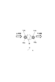
図2は、第1実施形態においてロボットハンドのフィンガーにより把持されたワークをカメラ側から見た平面図である。2つのマーク部材1501,1502は、レンズ332を通してカメラ本体331の画像センサ340から見える、つまり画像センサ340の撮像視野(画角)内を通過するようになっている。
FIG. 2 is a plan view of the work held by the fingers of the robot hand as seen from the camera side in the first embodiment. The two mark members 150 1 and 150 2 can be seen from the
また、ワークWの搬送中、マーク部材1501,1502がワークWの搬送方向Xに平行となるようにロボットハンド112が位置制御されている。この結果、マーク部材1502は、ワークWに対して搬送先側に位置し、マーク部材1501は、ワークWに対して搬送元側に位置することとなる。
The position of the
マーク部材1501,1502は、周囲からのコントラストが大きい部材が選ばれる。これにより、カメラ内部の処理で高速にマーク部材1501,1502を検出することが可能となる。マーク部材1501,1502は、平面視で円形状に形成されている。そして、マーク部材1501は、マーク部材1502と同じ大きさに設定されている。 As the mark members 150 1 and 150 2 , members having a large contrast from the surroundings are selected. As a result, it becomes possible to detect the mark members 150 1 and 150 2 at high speed by the process inside the camera. The mark members 150 1 and 150 2 are formed in a circular shape in plan view. The mark member 150 1 is set to have the same size as the mark member 150 2 .
なお、マーク部材1501,1502の形状やマーク部材1501,1502の配置位置は、以上の説明に限定するものではない。例えば、マーク部材1501,1502の形状は、直線帯状としても良いし、十字形状としても良い。また配置に関しても、ワークWに対して、搬送方向Xの上流側と下流側とにマーク部材1501,1502が配置されていれば、フィンガー1141,1142に限定するものではない。例えば、ロボットハンド112の掌底面にマーク部材が配置されていてもよい。また、可能であればワークW上にマーク部材が配置されていてもよい。また、マークは、マーク部材に限らず、マークとして識別可能なものであれば、どのような形態であってもよい。例えば、フィンガーや掌底面等、ロボットハンド自体に溝や色等のマークを付与してもよい。また、ロボットハンドにマークが付与されている場合に限らず、ワークにマークが付与されている場合であってもよい。
The arrangement position of the mark member 150 1, 150 2 of the shape and the mark member 150 1, 150 2 is not limited to the above description. For example, the shape of the mark members 150 1 and 150 2 may be a linear band shape or a cross shape. The arrangement is not limited to the fingers 114 1 and 114 2 as long as the mark members 150 1 and 150 2 are arranged on the upstream side and the downstream side of the work W in the transport direction X. For example, a mark member may be arranged on the palm bottom surface of the
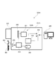
図3は、第1実施形態におけるカメラの内部構成を示したブロック図である。画像センサ340は、マトリックス状に配列された複数の画素を有し、所定の時間、露光することで、レンズ332を通してセンサ面上に結像した像を撮像画像として電気信号に変換するセンサである。画像センサ340は、画素毎に画素データをデジタルデータとして出力する。
FIG. 3 is a block diagram showing the internal configuration of the camera of the first embodiment. The
主な画像センサとしてCCD(Charge Coupled Device)イメージセンサと、CMOS(Complementary Metal Oxide Semiconductor)イメージセンサとがある。CCDイメージセンサは、全画素を同時に露光するグローバルシャッタを備えているため、移動体を撮像するのに向いている。これに対してCMOSイメージセンサは、水平スキャンごとに露光タイミングをずらして画像データを出力するローリングシャッタが一般的である。ローリングシャッタを有するCMOSイメージセンサで移動体を撮像すると水平方向ごとに露光タイミングが異なるため実際の形状から歪んでしまう。ただしCMOSイメージセンサでも画素ごとに一時的にデータを保存する仕組みを持ったものがあり、このようなセンサではグローバルシャッタを実現できるので移動体を撮像しても出力画像が歪まない。 Main image sensors include a CCD (Charge Coupled Device) image sensor and a CMOS (Complementary Metal Oxide Semiconductor) image sensor. Since the CCD image sensor includes a global shutter that exposes all pixels at the same time, it is suitable for capturing an image of a moving body. On the other hand, a CMOS image sensor is generally a rolling shutter that outputs image data by shifting the exposure timing for each horizontal scan. When an image of a moving object is picked up by a CMOS image sensor having a rolling shutter, the exposure timing is different in each horizontal direction, so that the actual shape is distorted. However, some CMOS image sensors have a mechanism for temporarily storing data for each pixel, and since such a sensor can realize a global shutter, the output image is not distorted even when the moving object is imaged.
第1実施形態では移動体を扱うため、画像センサ340として、CCDイメージセンサ、若しくはグローバルシャッタ付きのCMOSイメージセンサが望ましい。形状の変化が問題とならない検査であれば、通常のCMOSイメージセンサを用いることも可能である。なお後述するようにワークを待っている間のフレームレートを高めるために、全画素を出力するのではなく部分領域の画素を選択出力する。つまり、部分的な画素領域のみで撮像を行うことができる。
In the first embodiment, since a moving body is handled, a CCD image sensor or a CMOS image sensor with a global shutter is desirable as the
一般にCCDイメージセンサは、構造上水平方向にしか画素を選択できないのに対してCMOSイメージセンサは縦横自由に選択できる。以上よりグローバルシャッタ付きのCMOSイメージセンサが本実施形態に最も適している。 Generally, a CCD image sensor can select pixels only in the horizontal direction because of its structure, whereas a CMOS image sensor can freely select pixels vertically and horizontally. From the above, a CMOS image sensor with a global shutter is most suitable for this embodiment.
カメラ330は、制御部350と、記憶部355とを有している。記憶部355は、書き換え可能な不揮発性メモリ、例えばEEPROM(Electrically Erasable Programmable Read Only Memory)で構成され、設定情報が記憶されている。制御部350は、画素整列回路351、判別回路352、撮像制御回路353及び外部出力回路354を有して構成される。
The
画素整列回路351は、画像センサ340からの画素データを、後段の画像処理装置400に転送するために、画像センサ340から出力される同期信号(sync信号)に従って画素順を整列させたり、並列化したりする回路である。整列順は、転送インタフェースの規格により様々な形式が提案されている。
The
判別回路352は、画像センサ340中、選択された画素領域内で撮像された画像(データ)中に、マーク部材1501,1502の像(マーク像)が写り込んでいるか否かを判別する。また、判別回路352は、撮像条件(撮像に用いる画素領域)の変更や外部出力の有無の切替信号を発生する。
The
撮像制御回路353は、記憶部355から読み出した設定情報に応じて、画像センサ340及び光源361を制御する。具体的には、撮像制御回路353は、画像センサ340の複数の画素から画素群で構成された画素領域を、記憶部355の記憶データに従って選択して、選択した画素領域から画像を取得するように画像センサ340を制御する。つまり、撮像制御回路353は、選択した画素領域で撮像を行うように画像センサ340を制御する。また、撮像制御回路353は、光源361の点灯を制御する。
The
外部出力回路354は、インタフェースの規格に応じてデジタル信号をパラレルシリアル変換したり、冗長性を付加したりして転送に適した状態にする回路である。第1実施形態では、外部出力回路354は、判別回路352から入力を受けた切替信号に従い、画像を外部の画像処理装置400に出力するか否かを選択できるようになっている。
The
次に、制御部350および画像処理装置400による計測方法、具体的には制御部350による撮像方法について説明する。図4は、第1実施形態に係る撮像方法を示すフローチャートである。図5(a)〜図5(f)は、第1実施形態に係る撮像方法を説明するための模式図である。
Next, a measurement method by the
図5(a)〜図5(f)中、点線の画素領域が画像センサ340の全画素を示し、実線の画素領域が選択される画素領域341,342,346,347を示す。撮像制御回路353に選択される画素領域341,342,346,347の情報は、予め記憶部355に記憶されている。撮像制御回路353は、ロボット制御装置120や判別回路352からの信号に応じて、記憶部355を参照し、画像センサ340の複数の画素の中から、撮像に用いる画素群からなる画素領域を選択する。
In FIGS. 5A to 5F, the dotted pixel areas indicate all the pixels of the
まず、撮像制御回路353は、ワークWの移動を開始したことを示す開始信号をロボット制御装置120から入力したか否かを判断する(S1)。
First, the
撮像制御回路353は、開始信号を入力していない場合(S1:No)、つまりロボット110がワークWを搬送していない場合、開始信号を入力するまで待機状態となる。ロボット制御装置120が開始信号を出力したら、ロボット110は、ワークWを搬送していることになる。
When the start signal is not input (S1: No), that is, when the
撮像制御回路353は、開始信号を入力した場合(S1:Yes)、つまりワークWの搬送中、複数の画素のうち、図5(a)に示すように、搬送方向Xの上流側に位置する第1画素領域341を選択する。第1画素領域341は、画像センサ340の搬送方向Xの上流側(搬送元側)の辺縁部であり、画像センサ340の全画素のうちの一部分である。そして、撮像制御回路353は、第1画素領域341で撮像を行わせる(S2:第1撮像処理、第1撮像工程)。この第1画素領域341による撮像動作は、所定の時間間隔(サンプリング間隔)で行われる。画素整列回路351は、撮像した画像(データ)として、画像センサ340の第1画素領域341、つまり搬送方向Xの上流側の辺縁部のみの画素データを出力する。これにより、高速にサンプリングすることが可能となり、ワークWの高速移動にも対応可能となる。なお、第1画素領域341は、少数の画素のみでよく、例えば画像センサ340の搬送元側の辺縁部における1列の画素で構成されていてもよい。ここで、ステップS2において、外部出力回路354は、画像処理装置400への画像の出力を行わないよう、外部出力の設定がオフとなっている。
When the start signal is input (S1: Yes), that is, while the work W is being transported, the
次に、判別回路352は、まず、第1画素領域341から取得した画像(データ)に基づき、マーク像が画像に写り込んでいるか否かを判別する(S3)。ここで、マーク部材1501,1502のうち、搬送方向Xの下流側に位置するマーク部材1502が先に第1画素領域341の撮像視野に進入する。
Next, the
判別回路352は、ステップS3の判別の結果、マーク像が写り込んでいないと判別した場合(S3:No)、次のタイミングで再び第1画素領域341から取得した画像に基づき、マーク像が画像に写り込んでいるか否かを判別する。つまり、判別回路352は、第1画素領域341でマーク像を検出したか否かを判別する。
When it is determined in step S3 that the mark image is not reflected (S3: No), the
そして、判別回路352は、ステップS3の判別の結果、マーク像が画像に写り込んでいると判別した場合(S3:Yes)、検出したマーク像はマーク部材1501ではないので、これを無視するスルー動作処理を行う(S4)。そして、判別回路352は、スルー動作処理後、第1画素領域341から取得した画像に基づき、マーク像が画像に写り込んでいるか否かを判別する(S5)。つまり、マーク部材1502が第1画素領域341に撮像された段階では、ワークWは画像センサ340の撮像視野(画角)に進入していない。
When the
判別回路352は、ステップS5の判別の結果、マーク像が画像に写り込んでいないと判別した場合(S5:No)、次のタイミングで再び第1画素領域341から取得した画像に基づき、マーク像が画像に写り込んでいるか否かを判別する。
When the
ワークWが搬送方向Xに移動し、図5(b)のように搬送元側のマーク部材1501が第1画素領域341にて撮像されたとき、判別回路352は、ステップS5の判別の結果、マーク部材1501に対応するマーク像が画像に写り込んでいると判別する。
Move the workpiece W is in the conveying direction X, when the mark members 150 1 of transport origin side as shown in FIG. 5 (b) is captured in the
以上のステップS3〜S5が、第1画素領域341から取得した画像に基づきマーク部材1501が撮像されたか否かを判別する第1判別処理(第1判別工程)である。つまり、判別回路352は、ステップS3〜S5の第1判別処理において、第1画素領域341にて撮像した画像に1回目に写り込んだマーク像を無視(スルー)する(S3,S4)。そして、判別回路352は、第1画素領域341にて撮像した画像に2回目に写り込んだマーク像を、マーク部材1501と判別する(S5)。
Above steps S3~S5 is a first determination process in which the mark member 150 1 based on the image obtained from the
判別回路352は、ステップS5の判別の結果、マーク部材1501が撮像されたと判別した場合(S5:Yes)、外部出力回路354及び撮像制御回路353に切替信号を出力する。撮像制御回路353は、判別回路352からの信号の入力を受け、図5(c)に示すように、画像センサ340中、第1画素領域341よりも広域(高解像度)の画素領域346を選択する。そして、撮像制御回路353は、選択した画素領域346でワークWを撮像させる(S6:第1ワーク撮像処理、第1ワーク撮像工程)。このとき、撮像制御回路353は、ステップS6による撮像タイミングに同期して、光源361を点灯させる。
ここで、画素領域346は、画像センサ340中、全ての画素でもよいが、ワークWが撮像画像に写り込むのに十分な領域であれば、全ての画素である必要はない。第1実施形態では、ワークWの搬送中、画素領域346の撮像後に再度撮像を行うため、ワークWがオーバーランするのを防ぐために、ワークWが撮像画像に写り込む最小限の領域に設定するのが好ましい。
Here, the
また、外部出力回路354は、判別回路352からの信号の入力を受け、外部出力をオンに設定し、画素領域346からの撮像画像(第1撮像画像)のデータの入力を受けたとき、画像処理装置400に撮像画像のデータを出力する。
The
ここで、判別回路352による判別動作について詳細に説明する。マーク像の明るさと背景の明るさとの間の輝度に相当する輝度閾値と、撮像した画像データにマーク像が写り込んでいる場合の画素数に相当する画素閾値が予め記憶部355に記憶されている。
Here, the determination operation by the
判別回路352は、取得した画像データに対して2値化処理を施し、この2値化処理した画像データの画素データ(ピクセル)のうち、輝度閾値以上の明るい画素データ(ピクセル)の個数(画素数)をカウントする。次に、判別回路352は、カウントして得られた画素数が、画素閾値以上であるか、即ち画素閾値に達したか否かを判別する。画素数が画素閾値に達していれば、マーク像が画素領域341に撮像された画像に写り込んでいることになる。このように、判別回路352は、第1画素領域341にて撮像した画像にマーク像が写り込んだか否かを、第1画素領域341にて撮像した画像中の画素データの輝度に基づき判別する。
The
ここで、第1実施形態では、マーク部材1501とマーク部材1502の大きさが同じであるため、カウントした画素数のみではいずれのマーク部材のマーク像が検出されたのか判別が困難である。 Here, in the first embodiment, since the size of the mark member 150 1 and the size of the mark member 150 2 are the same, it is difficult to determine which mark member has the detected mark image only by the counted number of pixels. .
なお、ワークWの搬送中、第1画素領域341にて検出されるマーク像のうち、1回目に検出されるマーク像がマーク部材1502であり、その後、2回目に検出されるマーク像がマーク部材1501である。そして、第1画素領域341の撮像視野からマーク部材1502が抜けるまでは、カウントした画素数は画素閾値を下回らず、第1画素領域341の撮像視野からマーク部材1502が抜けると(または抜ける途中で)、画素数が画素閾値を下回る。具体的には、カウント数が極小値(例えば0)になる。そして、再びカウント数が画素閾値に達した場合には、次のマーク部材1501が第1画素領域341の撮像視野に進入したことになる。
Incidentally, during transport of the workpiece W, among the mark image detected by the
したがって、第1実施形態では、判別回路352は、第1画素領域341から取得した画像データ中の画素データの輝度が輝度閾値以上となる画素数をカウントする。判別回路352は、カウントした画素数が、最初に画素閾値以上となった場合、1回目に写り込んだマーク像を検出したこととなるので、未だ画角内にワークWは移動しておらず、カウントした画素数が下限閾値以下となるまで無視するスルー動作処理を行う。
Therefore, in the first embodiment, the
よって、判別回路352は、スルー動作処理中は、撮像制御回路353及び外部出力回路354に切替信号を出力しない。ここで、下限閾値は、予め記憶部355に設定情報として記憶されている。この下限閾値は、画素閾値よりも小さい値であり、極小値(例えば0)にしておいてもよい。
Therefore, the
判別回路352は、カウントした画素数が、再び画素閾値以上となった場合、2回目に写り込んだマーク像を検出したことになるので、マーク部材1502が撮像されたと判別する。
このように、第1実施形態では、カウントした画素数が最初に画素閾値に達しても、マーク部材1502が第1画素領域341の撮像視野を抜けて次のマーク部材1501が第1画素領域341の撮像視野に進入するまでは、判別動作を継続する。
Thus, in the first embodiment, counted even when the number of pixels is first reached the pixel threshold, the mark member 150 2 next mark member 150 1 is first pixel exits the imaging visual field of the
その後、2回目にマーク像が検出されたときに初めて1回目の外部出力用の撮像画像を得る撮像タイミングとなるため、判別回路352は、撮像制御回路353及び外部出力回路354に切替信号を出力する。
After that, when the mark image is detected for the second time, the image pickup timing for obtaining the first taken image for external output is reached. Therefore, the
切替信号を受けた撮像制御回路353は、ステップS6において、画像取得範囲を、図5(c)に示すように、ワークW全体が撮像視野に入る範囲、即ち広域(高解像度)の画素領域346に切り替え、光源361の発光と同期してワークWの撮像を行う。また、切替信号を受けた外部出力回路354は、外部出力をオンに設定し、画像処理装置400に1つ目の撮像画像を出力する。
In step S6, the
このように、第1画素領域341を用いてワークWが画像センサ340の撮像視野の搬送元側の辺縁部に到達したことが検出され、瞬時に画素領域346に切り替えられてワークWの撮像が行われる。
In this way, it is detected that the work W has reached the edge on the transport source side of the imaging field of view of the
1つ目の画像撮像が終了した後、つまり撮像後のワークWの搬送中、撮像制御回路353は、即時、複数の画素のうち、図5(d)に示すように、搬送方向Xの下流側に位置する第2画素領域342を選択する。第2画素領域342は、画像センサ340の搬送方向Xの下流側(搬送先側)の辺縁部であり、画像センサ340の全画素のうちの一部分である。そして、撮像制御回路353は、第2画素領域342で撮像を行わせる(S7:第2撮像処理、第2撮像工程)。この第2画素領域342による撮像動作は、所定の時間間隔(サンプリング間隔)で行われる。画素整列回路351は、撮像した画像データとして、画像センサ340の第2画素領域342、つまり搬送方向Xの下流側の辺縁部のみの画素データを出力する。これにより、高速にサンプリングすることが可能となり、ワークWの高速移動にも対応可能となる。なお、第2画素領域342は、少数の画素のみでよく、例えば画像センサ340の搬送先側の辺縁部における1列の画素で構成されていてもよい。ここで、ステップS7において、撮像制御回路353は、1回目の画像出力後、画像処理装置400への画像データの出力を行わないよう、外部出力回路354の外部出力の設定をオフにする。
After the completion of the first image capturing, that is, during the transportation of the workpiece W after the imaging, the
次に、判別回路352は、第2画素領域342から取得した画像に基づき、マーク部材1502が撮像されたか否か(つまり、マーク部材1502を検出したか否か)を判別する(S8:第2判別処理、第2判別工程)。ここで、マーク部材1501,1502のうち、搬送方向Xの下流側に位置するマーク部材1502が先に第2画素領域341の撮像視野に進入する。つまり、マーク部材1502が検出された時点でワークWは画像センサ340の撮像視野の辺縁部に到達していることになる。したがって、ステップS8では、判別回路352は、第2画素領域341で撮像を開始してから最初にマーク像を検出したか否かを判別する。
Next, the
判別回路352は、ステップS8の判別の結果、マーク部材1502が撮像されていないと判別した場合(S8:No)、次のタイミングで再び第2画素領域342から取得した画像に基づき、マーク部材1502が撮像されたか否かを判別する。
そして、判別回路352は、ステップS8の判別の結果、マーク部材1502が撮像されたと判別した場合(S8:Yes)、つまり、図5(e)に示す状態となったとき、外部出力回路354および撮像制御回路353に切替信号を出力する。撮像制御回路353は、判別回路352からの信号の入力を受け、図5(f)に示すように、画像センサ340中、第2画素領域342よりも広域(高解像度)の画素領域347を選択する。そして、撮像制御回路353は、選択した画素領域347でワークWを撮像させる(S9:第2ワーク撮像処理、第2ワーク撮像工程)。このとき、撮像制御回路353は、ステップS9による撮像タイミングに同期して、光源361を点灯させる。
The
ここで、画素領域347は、画像センサ340中、全ての画素でもよいが、ワークWが撮像画像に写り込むのに十分な領域であれば、全ての画素である必要はない。
Here, the
また、外部出力回路354は、判別回路352からの信号の入力を受け、外部出力をオンに設定し、画素領域347からの撮像画像(第2撮像画像)のデータの入力を受けたとき、画像処理装置400に撮像画像のデータを出力する。
Further, the
このように、ワークWの搬送により、マーク部材1502がマーク部材1501に先立って第2画素領域342の撮像視野に進入することになる。したがって、第1実施形態では、判別回路352は、第2画素領域342から取得した画像中の画素データの輝度が輝度閾値以上となる画素数をカウントする。そして、判別回路352は、カウントした画素数が、最初に画素閾値以上となった場合、マーク部材1502が撮像されたことになるので、撮像制御回路353及び外部出力回路354に切替信号を出力する。
As described above, the conveyance of the work W causes the mark member 150 2 to enter the imaging visual field of the
切替信号を受けた撮像制御回路353は、ステップS9において、画像取得範囲を、図5(f)に示すように、ワークW全体が撮像視野に入る範囲、即ち広域(高解像度)の画素領域347に切り替え、光源361の発光と同期してワークWの撮像を行う。また、切替信号を受けた外部出力回路354は、外部出力をオンに設定し、画像処理装置400に2つ目の撮像画像を出力する。
In step S9, the
このように、第2画素領域342を用いてワークWが画像センサ340の撮像視野の搬送先側の辺縁部に到達したことが検出され、瞬時に画素領域347に切り替えられてワークWの撮像が行われる。
In this way, it is detected that the workpiece W has reached the edge portion on the conveyance destination side of the imaging field of the
その後、外部出力回路354は、外部出力をオフに設定し(S10)、処理を終了する。2つの撮像画像を取得した画像処理装置400は、前述した撮像方法により得られた2つの撮像画像に基づき、ワークWを3次元計測する。
After that, the
以上、ロボット制御装置120や画像処理装置400で撮像タイミング(画素領域の切り替え)を制御することなく、カメラ330内部の制御部350の処理により、視差が大きい(ほぼ最大となる)2つの撮像画像を自動で取得することができる。このように、簡単な構成でワークの搬送を停止させることなく単眼ステレオ法に適した2つの撮像画像を得ることができる。よって、画像処理装置400において、単眼ステレオ法によりワークWの高精度な3次元計測が可能となる。
As described above, the two captured images with a large parallax (almost maximum) are processed by the processing of the
また、搬送中のワークWを異なる撮像タイミングで撮像させるために、制御部350が画像処理装置400やロボット制御装置120等の外部コントローラと通信する必要がないので、通信時間が削減され、ワークWの高速移動にも対応することができる。
Further, since the
以上の動作により、単眼ステレオ法に適した相互の撮像位置の違いがほぼ最大の2つの撮像画像が得られることになる。単眼ステレオ法では、この差が基線長に相当し、基線長が大きいほど奥行き方向のデジタル分解能が上がるため、より高精度の計測が可能となる。 With the above operation, two picked-up images suitable for the monocular stereo method and having almost the same difference between the picked-up positions can be obtained. In the monocular stereo method, this difference corresponds to the base line length, and the larger the base line length, the higher the digital resolution in the depth direction. Therefore, more accurate measurement is possible.
ここで、第1実施形態では、判別回路352は、画素信号のストリームと同期して高速処理を行うため、ロジック回路(ハードウエア)で構成されていている。図6は、第1実施形態に係る判別回路を示す回路図である。判別回路352は、コンパレータ371,373と、カウンタ372,374とを有している。コンパレータ371は、入力した画素データの輝度が、予め設定された輝度閾値以上であるか否かを判別する。カウンタ372は、輝度閾値以上の輝度である画素の数をカウントする。コンパレータ373は、カウンタ372にてカウントされた画素数が画素閾値以上であるか否かを判別する。カウンタ374は、前述したスルー動作処理を行うためのカウンタである。
Here, in the first embodiment, the
コンパレータ371,373及びカウンタ372,374は、画像センサ340から出力される画素データや画像フレームと同期した同期信号によりセットリセットされるため、ソフトウエアによる処理と比較して無駄なく、瞬時に判別を行うことが可能となる。
Since the
図7(a)〜図7(d)は、画像上のマーク像と、選択された画素領域により撮像された画素とを示す模式図である。図7(a)に示すように、マーク部材1501,1502を撮像したマーク像MKIは、円形状であり、画素領域341,342により撮像された領域SIは、1列の画素データである。
FIG. 7A to FIG. 7D are schematic diagrams showing the mark image on the image and the pixels imaged by the selected pixel area. As shown in FIG. 7A, the mark image MKI obtained by imaging the mark members 150 1 and 150 2 has a circular shape, and the area SI captured by the
画像上でマーク像MKIの直径が領域SIの長さよりも長くなるように、マーク部材1501,1502および画素領域341,342が設定されている。この場合、画素閾値は、全画素が明画素となる値、つまり画素領域341,342の1列の画素数と同じ値に設定されている。よって、画素領域341,342により撮像された画像の全ての画素データにおいて輝度閾値以上となった場合に、マーク像が写り込んだと判別される。
The mark members 150 1 and 150 2 and the
図7(b)には、想定した基準位置をマーク部材が通過した場合に最初に判別条件を満たす画像が図示されている。図7(c)及び図7(d)には、マーク部材の軌道が想定していた基準位置からそれぞれ僅かに下方、上方にずれた場合に最初に判別条件を満たす画像が図示されている。このように、マーク部材1501,1502が目標軌道に対して僅かなずれ量であれば、マークの検出が可能である。なお、図7(c)又は図7(d)よりもさらにずれた場合には、マークは検出されず、ワークWの撮像が失敗となる。このようにマーク部材1501,1502および画素領域341,342を設定することにより、ワークWを撮像する際のワークWの位置精度を許容範囲内に限定することができる。したがって、2つの撮像画像に基づく3次元計測の精度を高めることができる。また、マーク直径と選択範囲画素数に相当する分、マーク部材の軌道が上下にずれたりマーク部材が斜め方向から撮像視野に進入したりしたとしても、許容範囲内であればワークを撮像できる。このように、ワークWを搬送するロボット110の変動要因による移動中の撮像ミスを防ぐことが可能となる。
FIG. 7B shows an image that first satisfies the determination condition when the mark member passes the assumed reference position. FIG. 7C and FIG. 7D show images that first satisfy the determination condition when the trajectory of the mark member deviates slightly downward and upward from the assumed reference position, respectively. As described above, if the mark members 150 1 and 150 2 have a slight deviation amount from the target trajectory, the mark can be detected. In addition, when the deviation is further from that in FIG. 7C or 7D, the mark is not detected, and the image pickup of the work W fails. By setting the mark members 150 1 and 150 2 and the
ここで、画像処理装置400で実施される単眼ステレオ法の原理について説明する。図8(a)はステレオカメラを用いる3次元測定法を示す原理図である。図8(b)は単眼ステレオ法による3次元測定法を示す原理図である。
Here, the principle of the monocular stereo method implemented by the
ステレオカメラによるステレオ法では、2台のカメラ330R,330Lを使用して、同じ撮像タイミングで静止したワークWを撮像した際に生じる視差を利用して、2つの撮像画像IR,ILにより3次元計測を行う。一方、単眼ステレオ法では、1台のカメラ330を使用して、ワークWを移動させることによって視差のある2つの撮像画像I1,I2を取得し、3次元計測を行う。
In the stereo method using a stereo camera, two
カメラ330のレンズの焦点距離をf、ロボットハンドの掌底面等に設定した基準となる面(基準面)での撮像倍率をA、2つの撮像画像I1,I2間でのワークWの移動量をB、計測する点の画像I1,I2上での視差をδとする。基準面からの計測点の光軸方向の位置Zは、Z=A×δ×f/Bと表される。即ち、単眼ステレオ法においては、視差1画素あたりの分解能は、ワークWの移動量に反比例(微細)となる。
The focal length of the lens of the
第1実施形態によれば、撮像したときのワークWの2つの位置の差をほぼ最大とできるため、単眼ステレオ法による3次元計測を精度よく行うことが可能となる。また、3次元計測を行うための撮像とマークの位置検出を同一の画像センサ340で行うため、位置検出器を用いる方法と比較して、位置合わせやタイミング調整が不要となる。マーク部材の待ち受け時には、ごく少数の画素データのみを画素領域341,342で取得するため、高速サンプリングが可能である。例えば、100万画素の画像センサに対して、画素領域341,342を30画素程度にすることが可能であり、判別処理も複雑な処理が不要なので、実験的に数十[kHz]での高速サンプリングが実現できる。この結果、ワークWを一旦停止させる必要もなく、ワークWを高速移動させることができるので、スループットを上げることができる。
According to the first embodiment, the difference between the two positions of the work W at the time of capturing an image can be almost maximized, so that the three-dimensional measurement by the monocular stereo method can be accurately performed. In addition, since the
また、第1実施形態によれば、カメラ330の制御部350は、ロボット制御装置120からワークWの位置情報を逐一取得しなくても、ワークを撮像する撮像タイミングを、画像センサ340の検出結果に基づき自動的に決めることができる。
Further, according to the first embodiment, the
また、第1実施形態によれば、フィンガー1141,1142にマーク部材1501,1502を付与したので、ロボットハンド112がワークWを把持した場合、マーク部材1501,1502がワークWのサイズに応じてフィンガーとともに移動する。これにより、マーク部材1501,1502がワークWの上下流側の端部に近接するように調整されることになる。したがって、異なるサイズのワークWを撮像する場合であっても、精度よく、画像センサ340の撮像視野の搬送方向上下流の両端部近傍でワークWを撮像することができる。よって、各種サイズのワークWに対し、簡単な構成で3次元計測の精度を向上させることができる。
Further, according to the first embodiment, since the mark members 150 1 and 150 2 are provided to the fingers 114 1 and 114 2 , when the
[第2実施形態]
次に、本発明の第2実施形態に係る生産システムについて説明する。図9は、第2実施形態に係る生産システムの概略構成を示す模式図である。図9において、図1と同様の構成については同一符号を付している。
[Second Embodiment]
Next, a production system according to the second embodiment of the present invention will be described. FIG. 9 is a schematic diagram showing a schematic configuration of the production system according to the second embodiment. 9, the same components as those in FIG. 1 are designated by the same reference numerals.
第2実施形態の生産システム100Aは、計測システム200Aと、ワークWを搬送する搬送装置であるロボット110と、ロボット制御装置120と、上流側装置である供給装置500と、下流側装置である排出装置600と、を備えている。
The
ロボットハンド112のフィンガー1141,1142には、マークであるマーク部材1501,1502が付与されている。各マーク部材1501,1502は、再帰反射性を有する部材(つまり、再帰反射材)となっている。
Mark members 150 1 and 150 2 as marks are attached to the fingers 114 1 and 114 2 of the
計測システム200Aは、撮像システム300Aと、画像処理装置400と、を備えている。撮像システム300Aは、単眼の撮像装置であるカメラ330Aと、大光源である光源361と、小光源である光源362と、を備えている。
The
カメラ330Aは、検査計測対象であるワークWを自動で撮像するデジタルカメラである。カメラ330Aは、撮像部であるカメラ本体331Aと、カメラ本体331Aに取り付けられたレンズ332とを有する。カメラ本体331Aは、画像センサ340と、画像センサ340を制御する制御部350Aとを有している。カメラ330Aは、不図示の架台等に固定して設置されている。照明装置である光源361は、例えば閃光を発する閃光装置(ストロボ)であり、ワークWを撮像する際にワークWに光を照射する。
The
光源362は、マーク部材1501,1502に光を照射するものであり、レンズ332近傍に配置されており、光源361と比較して照度が低く、発光部面積が狭く設定されている。ワークに鏡面または反射率が高い面が存在した場合に照度を低くしても光源から直接カメラに正反射光が入射され、後述する再帰反射によるものと区別がつかなくなる。しかし発光部面積を狭くしておけば後述する再帰反射材からの反射と明領域の面積の差で容易に区別することができる。
The
図10(a)〜図10(d)は、再帰反射材の一例と原理を示した説明図である。再帰反射材の一例として、図10(a)に示すように、マイクロビーズと呼ばれるガラス等の高屈折材料151と底面に設置した反射材152とを用いた方式のものがある。図10(b)に示すように、高屈折材料151に入射した光は、高屈折材料151による2度の屈折により元の入射方向に反射する。このように、どの方向から入射した光も元の方向に反射する現象を再帰反射と呼んでいる。高屈折率材(ビーズ)151の大きさを小さくして隙間なく敷き詰めれば、マクロ的には面全体で反射していると見做せる。
10A to 10D are explanatory views showing an example and a principle of the retroreflective material. As an example of the retroreflective material, as shown in FIG. 10A, there is a system using a high
また、再帰反射材の他の例として、図10(c)に示すように、互いに所定の角をなし凹状になるように張り合わされた平面鏡153からなるコーナーキューブを用いた方式のものがある。この場合も図10(d)に示すように、入射した光は平面鏡153で何回か反射することによって元の方向に反射するという再帰反射性を示す。なお、再帰反射材については、これらの例に限定するものではなく、いかなる再帰反射材であってもよい。
Further, as another example of the retroreflective material, as shown in FIG. 10 (c), there is a system using a corner cube composed of plane mirrors 153 that are bonded to each other so as to form a predetermined angle and have a concave shape. Also in this case, as shown in FIG. 10D, the incident light is reflected several times by the
図11は、第2実施形態におけるカメラの内部構成を示したブロック図である。カメラ330Aは、制御部350Aと、記憶部355とを有している。制御部350Aは、画素整列回路351、判別回路352、撮像制御回路353、外部出力回路354及び切替回路356を有して構成される。切替回路356は、撮像制御回路353の制御により、照明する光源361,362を排他的に切り替え、撮像制御回路353からの同期信号により、光源361又は光源362を発光させる。
FIG. 11 is a block diagram showing the internal configuration of the camera of the second embodiment. The
次に、制御部350Aおよび画像処理装置400による計測方法、具体的には制御部350Aによる撮像方法について説明する。図12は、第2実施形態に係る撮像方法を示すフローチャートである。図13(a)〜図13(f)は、第2実施形態に係る撮像方法を説明するための模式図である。
Next, a measurement method by the
まず、撮像制御回路353は、ワークWの移動を開始したことを示す開始信号をロボット制御装置120から入力したか否かを判断する(S11)。
First, the
撮像制御回路353は、開始信号を入力していない場合(S11:No)、つまりロボット110がワークWを搬送していない場合、開始信号を入力するまで待機状態となる。ロボット制御装置120が開始信号を出力したら、ロボット110は、ワークWを搬送していることになる。
When the start signal is not input (S11: No), that is, when the
撮像制御回路353は、開始信号を入力した場合(S11:Yes)、つまりワークWの搬送中、複数の画素のうち、図13(a)に示すように、搬送方向Xの上流側に位置する第1画素領域341を選択する。そして、撮像制御回路353は、第1画素領域341で撮像を行わせる(S12:第1撮像処理、第1撮像工程)。この第1画素領域341による撮像動作は、所定の時間間隔(サンプリング間隔)で行われる。画素整列回路351は、撮像した画像データとして、画像センサ340の第1画素領域341、つまり搬送方向Xの上流側の辺縁部のみの画素データを出力する。これにより、高速にサンプリングすることが可能となり、ワークWの高速移動にも対応可能となる。なお、第1画素領域341は、少数の画素のみでよく、例えば画像センサ340の搬送元側の辺縁部における1列の画素で構成されていてもよい。ここで、ステップS12において、外部出力回路354は、画像処理装置400への画像データの出力を行わないよう、外部出力の設定がオフとなっている。また、切替回路356は、撮像制御回路353により、光源362に切り替えられており、撮像中、光源362が点灯するように制御されている。光源362は照度が小さく、ワークWやロボットハンド112の構造物などを十分に照らすことができないので、図13(a)の時点では、画角内いたるところでほぼ真っ暗となる。
When the start signal is input (S11: Yes), that is, while the work W is being transported, the
次に、判別回路352は、まず、第1画素領域341から取得した画像に基づき、マーク像が画像に写り込んでいるか否か判別する(S13)。判別回路352は、ステップS3の判別の結果、マーク像が写り込んでいないと判別した場合(S13:No)、次のタイミングで再び第1画素領域341から取得した画像に基づき、マーク像が画像に写り込んでいるか否かを判別する。つまり、判別回路352は、第1画素領域341でマーク像を検出したか否かを判別する。
Next, the
そして、判別回路352は、ステップS13の判別の結果、マーク像が画像に写り込んでいると判別した場合(S13:Yes)、検出したマーク像はマーク部材1501ではないので、これを無視するスルー動作処理を行う(S14)。そして、判別回路352は、スルー動作処理後、第1画素領域341から取得した画像に基づき、マーク像が画像に写り込んでいるか否かを判別する(S15)。つまり、マーク部材1502が第1画素領域341に撮像された段階では、ワークWは画像センサ340の撮像視野(画角)に進入していない。
When the
判別回路352は、ステップS15の判別の結果、マーク像が画像に写り込んでいないと判別した場合(S15:No)、次のタイミングで再び第1画素領域341から取得した画像に基づき、マーク像が画像に写り込んでいるか否かを判別する。
When it is determined that the mark image is not reflected in the image as a result of the determination in step S15 (S15: No), the
ワークWが搬送方向Xに移動し、図13(b)のように搬送元側のマーク部材1501が第1画素領域341にて撮像されたとき、判別回路352は、ステップS15の判別の結果、マーク部材1501に対応するマーク像が画像に写り込んでいると判別する。
Move the workpiece W is in the conveying direction X, when the 13 mark member 150 1 of the transfer origin side as (b) is captured in the
以上のステップS13〜S15が、第1画素領域341から取得した画像に基づきマーク部材1501が撮像されたか否かを判別する第1判別処理(第1判別工程)である。つまり、判別回路352は、ステップS13〜S15の第1判別処理において、第1画素領域341にて撮像した画像に1回目に写り込んだマーク像を無視(スルー)する(S13,S14)。そして、判別回路352は、第1画素領域341にて撮像した画像に2回目に写り込んだマーク像を、マーク部材1501と判別する(S15)。
Above steps S13~S15 is a first determination process in which the mark member 150 1 based on the image obtained from the
判別回路352は、ステップS15の判別の結果、マーク部材1501が撮像されたと判別した場合(S15:Yes)、外部出力回路354及び撮像制御回路353に切替信号を出力する。撮像制御回路353は、判別回路352からの信号の入力を受け、図15(c)に示すように、画像センサ340中、第1画素領域341よりも広域(高解像度)の画素領域346を選択する。そして、撮像制御回路353は、選択した画素領域346でワークWを撮像させる(S16:第1ワーク撮像処理、第1ワーク撮像工程)。このとき、撮像制御回路353は、ステップS16による撮像タイミングに同期して、光源361を点灯させるよう、切替回路356を制御する。
なおワークWの移動速度が速い場合、カメラ330Aにおいて短いシャッター速度が必要であり、画像処理装置400における画像処理を可能とする明るさの画像を得るためには、光源361の照度を強くしなければならない。単純に強くしてしまうと周囲の画像処理装置に影響を与えるが、シャッターと同期して発光するようにすれば、発光時間が極短時間のため、画像処理装置相互の干渉を防ぐことができる。後述する2回目に画像処理装置400に出力する画像を撮像する際も同様である。
Note that when the moving speed of the work W is fast, a short shutter speed is required in the
ここで、画素領域346は、画像センサ340中、全ての画素でもよいが、ワークWが撮像画像に写り込むのに十分な領域であれば、全ての画素である必要はない。第2実施形態では、ワークWの搬送中、画素領域346の撮像後に再度撮像を行うため、ワークWがオーバーランするのを防ぐために、ワークWが撮像画像に写り込む最小限の領域に設定するのが好ましい。
Here, the
また、外部出力回路354は、判別回路352からの信号の入力を受け、外部出力をオンに設定し、画素領域346からの撮像画像(第1撮像画像)のデータの入力を受けたとき、画像処理装置400に撮像画像のデータを出力する。
The
1つ目の画像撮像が終了した後、つまり撮像後のワークWの搬送中、撮像制御回路353は、即時、複数の画素のうち、図13(d)に示すように、搬送方向Xの下流側に位置する第2画素領域342を選択する。第2画素領域342は、画像センサ340の搬送方向Xの下流側(搬送先側)の辺縁部である。そして、撮像制御回路353は、第2画素領域342で撮像を行わせる(S17:第2撮像処理、第2撮像工程)。この第2画素領域342による撮像動作は、所定の時間間隔(サンプリング間隔)で行われる。画素整列回路351は、撮像した画像データとして、画像センサ340の第2画素領域342、つまり搬送方向Xの下流側の辺縁部のみの画素データを出力する。これにより、高速にサンプリングすることが可能となり、ワークWの高速移動にも対応可能となる。なお、第2画素領域342は、少数の画素のみでよく、例えば画像センサ340の搬送先側の辺縁部における1列の画素で構成されていてもよい。ここで、ステップS17において、撮像制御回路353は、1回目の画像出力後、画像処理装置400への画像データの出力を行わないよう、外部出力回路354の外部出力の設定をオフにする。また、切替回路356は、撮像制御回路353により、光源362に切り替えられ、撮像中、光源362が点灯するように制御されている。
After the first image capturing is completed, that is, during the transportation of the workpiece W after the capturing, the
次に、判別回路352は、第2画素領域342から取得した画像に基づき、マーク部材1502が撮像されたか否か(つまり、マーク部材1502を検出したか否か)を判別する(S18:第2判別処理、第2判別工程)。ここで、マーク部材1501,1502のうち、搬送方向Xの下流側に位置するマーク部材1502が先に第2画素領域341の撮像視野に進入する。つまり、マーク部材1502が検出された時点でワークWは画像センサ340の撮像視野の辺縁部に到達していることになる。したがって、ステップS18では、判別回路352は、第2画素領域341で撮像を開始してから最初にマーク像を検出したか否かを判別する。
Then, the
判別回路352は、ステップS18の判別の結果、マーク部材1502が撮像されていないと判別した場合(S18:No)、次のタイミングで再び第2画素領域342から取得した画像に基づき、マーク部材1502が撮像されたか否かを判別する。
そして、判別回路352は、ステップS18の判別の結果、マーク部材1502が撮像されたと判別した場合(S18:Yes)、つまり、図13(e)に示す状態となったとき、外部出力回路354および撮像制御回路353に切替信号を出力する。撮像制御回路353は、判別回路352からの信号の入力を受け、図13(f)に示すように、画像センサ340中、第2画素領域342よりも広域(高解像度)の画素領域347を選択する。そして、撮像制御回路353は、選択した画素領域347でワークWを撮像させる(S19:第2ワーク撮像処理、第2ワーク撮像工程)。このとき、撮像制御回路353は、ステップS19による撮像タイミングに同期して、光源361を点灯させるよう、切替回路356を制御する。
The
ここで、画素領域347は、画像センサ340中、全ての画素でもよいが、ワークWが撮像画像に写り込むのに十分な領域であれば、全ての画素である必要はない。
Here, the
また、外部出力回路354は、判別回路352からの信号の入力を受け、外部出力をオンに設定し、画素領域347からの撮像画像(第2撮像画像)のデータの入力を受けたとき、画像処理装置400に2つ目の撮像画像のデータを出力する。
Further, the
このように、第2画素領域342を用いてワークWが画像センサ340の撮像視野の搬送先側の辺縁部に到達したことが検出され、瞬時に画素領域347に切り替えられてワークWの撮像が行われる。
In this way, it is detected that the workpiece W has reached the edge portion on the conveyance destination side of the imaging field of the
その後、外部出力回路354は外部出力がオフ、切替回路356は全光源361,362の点灯をオフ(消灯)し、(S20)、処理を終了する。2つの撮像画像を取得した画像処理装置400は、前述した撮像方法により得られた2つの撮像画像に基づき、第1実施形態と同様の計算処理で、ワークWを3次元計測する。
After that, the external output of the
第2実施形態では、再帰反射性を有するマーク部材1501,1502が撮像視野に入ると、図13(b)、図13(d)及び図13(e)に示すように、再帰反射性を有するマーク部材1501,1502が周囲よりも明るい像として画像に写り込む。 In the second embodiment, when the mark members 150 1 and 150 2 having retroreflectivity enter the imaging field of view, as shown in FIGS. 13B, 13D, and 13E, retroreflectivity is exhibited. The mark members 150 1 and 150 2 having the are reflected in the image as an image brighter than the surroundings.
光源362は、カメラ330レンズ332の近傍に配置されている。このため、マーク部材1501,1502からの再帰反射光は、光源362の設置方向、すなわちレンズ332の方向に効率よく反射される。これにより、再帰反射材のマーク部材1501,1502のみ、撮像視野中のどこにあっても、明るいマーク像が画像に写り込むこととなり、また背景の明るさはほぼ0となる。したがって、背景とマーク像との間で高いコントラストを得ることができる。
The
よって、カメラ内のマーク判別アルゴリズムは、静的な2値化および明画素数判別のような簡素なアルゴリズムでマークを検出することが可能となる。以上のアルゴリズムは、ハードロジック実装に向いており、判別回路352を、第1実施形態で説明した図6に示すようなロジック回路で構成することが可能となる。よって、画像センサ340からの画像出力のストリームを乱さずに判別回路352を実装できるため、選択する画素の少なさに加えて、さらに高速かつ安定的にマークを検出することが可能となる。
Therefore, the mark discrimination algorithm in the camera can detect the mark by a simple algorithm such as static binarization and bright pixel number discrimination. The above algorithm is suitable for hard logic implementation, and the
以上の動作により、単眼ステレオ法に適した視差がほぼ最大となる2つの撮像画像を、ワークの搬送を停止させることなく安定して得られることになる。単眼ステレオ法ではこの差が基線長に相当し、基線長が大きいほど奥行き方向のデジタル分解能が上がるためより高精度の測定が可能となる。特に第2実施形態では、マークのコントラストが高く、検出の精度や高速性が極めて高いため、よりワークの3次元計測の精度が向上する。 With the above operation, two captured images suitable for the monocular stereo method and having the substantially maximum parallax can be stably obtained without stopping the conveyance of the work. In the monocular stereo method, this difference corresponds to the base line length, and the larger the base line length, the higher the digital resolution in the depth direction, and thus the more accurate measurement becomes possible. Particularly in the second embodiment, the mark contrast is high, and the detection accuracy and high speed are extremely high, so that the accuracy of the three-dimensional measurement of the work is further improved.
[第3実施形態]
次に、本発明の第3実施形態に係る計測システムにおける計測方法について説明する。図14は、第3実施形態に係る計測方法を示すフローチャートである。計測システムの構成は、第1実施形態又は第2実施形態と同様である。第1、第2実施形態では、画像処理装置400において、ロボット110の撮像間隔での移動量を用いて、3次元計測する場合について説明した。第3実施形態では、2つのマーク部材1501,1502間の距離または直径などのサイズδMを予め測定しておくことにより、ロボット110(ロボット制御装置120)からの情報を使用せずに3次元測定を行う。以下、計測方法について具体的に説明する。なお、マーク部材1501,1502間の距離やサイズのほかに、カメラ330の焦点距離fも予め別手段で測定されているとする。
[Third Embodiment]
Next, a measuring method in the measuring system according to the third embodiment of the present invention will be described. FIG. 14 is a flowchart showing the measuring method according to the third embodiment. The configuration of the measurement system is similar to that of the first embodiment or the second embodiment. In the first and second embodiments, the case where the
以下、マーク部材1501,1502間の距離を用いて計測する場合について説明する。 Hereinafter, a case where measurement is performed using the distance between the mark members 150 1 and 150 2 will be described.
まず、画像処理装置400は、1枚目の撮像画像から、マーク部材1501,1502間の画素数δm1を計測する(S21)。
First, the
次に、画像処理装置400は、マーク部材1501,1502間の距離δMと画素数δm1から、マーク部材1501,1502を含む基準面でのカメラ330の光学倍率(1画素あたりの距離)A1とワーキングディスタンスW1とを求める(S22)。
Next, the
画像処理装置400は、2枚目の撮像画像からも同様にしてマーク部材1501,1502間の画素数δm2を計測し(S23)、カメラの光学倍率A2とワーキングディスタンスW2とを求める(S24)。
The
画像処理装置400は、2枚目の撮像画像を1枚目の撮像画像と同じ倍率になるように画像変換を行い、2つの画像間で同じマーク部材の位置の差を求め、これに光学倍率A1を掛ける(S25)。この演算により求めた値がワークWの移動量Bに相当する。なお、搬送装置であるロボット110が光軸に垂直な面に沿ってワークWを移動するように調整されている場合は、倍率調整は不要となる。
The
画像処理装置400は、2枚目の画像を1枚目の画像と同じ倍率になるように画像変換を行い、2つの画像間で計測したい点の視差δを測定する(S26)。
The
画像処理装置400は、これまでに求めた、カメラ330の焦点距離f、ワークWの移動量B、1枚目の光学倍率A1、計測点の視差δを用いて、単眼ステレオ法の計測式Z=A1×δ×f/Bで計測点の光軸方向の位置Zを算出する(S27)。
The
第3実施形態によれば、ロボット110側の情報を使うことなく、ワークWの搬送を止めることなく、3次元計測を実施することができる。
According to the third embodiment, it is possible to perform three-dimensional measurement without using the information on the
なおマーク部材1501,1502のサイズを使用する場合、ステップS21〜S24と同様にして、マーク部材1501とマーク部材1502の付近の光学倍率から、1枚目の画像上の基準面、2枚目の画像上の基準面の傾きを求めることができる。このため、ワークWの搬送方向Xが水平方向に対して外れて移動していても、正確に3次元計測が可能となる。 When the sizes of the mark members 150 1 and 150 2 are used, similar to steps S21 to S24, from the optical magnification in the vicinity of the mark members 150 1 and 150 2 , the reference plane on the first image, The inclination of the reference plane on the second image can be calculated. Therefore, even if the conveyance direction X of the workpiece W is deviated from the horizontal direction, the three-dimensional measurement can be accurately performed.
本発明は、以上説明した実施形態に限定されるものではなく、本発明の技術的思想内で多くの変形が可能である。また、本発明の実施形態に記載された効果は、本発明から生じる最も好適な効果を列挙したに過ぎず、本発明による効果は、本発明の実施形態に記載されたものに限定されない。 The present invention is not limited to the embodiments described above, and many modifications can be made within the technical idea of the present invention. Further, the effects described in the embodiments of the present invention only list the most suitable effects that result from the present invention, and the effects according to the present invention are not limited to those described in the embodiments of the present invention.
上述した実施形態では、ロボットが、6軸のロボットアームと2指のロボットハンドの場合について説明したが、軸数及び指数はこれに限定するものではない。また、搬送装置がロボットである場合について説明したが、これに限定するものではなく、カメラの画角内をワークが通過するようにワークを移動させることができる装置であれば、どのような搬送装置であってもよい。 In the above embodiment, the case where the robot is a 6-axis robot arm and a 2-finger robot hand has been described, but the number of axes and the index are not limited to this. Further, although the case where the transfer device is a robot has been described, the present invention is not limited to this, and any transfer device can be used as long as it can move the work so that the work passes within the angle of view of the camera. It may be a device.
図15(a)及び図15(b)は、搬送装置の他の例を示す模式図である。例えば図15(a)に示すように、搬送装置110Aが、搬送体としてベルトコンベア111Aと、保持体としてワークWが載置されるトレー112Aと、を有する場合であってもよい。マーク部材1501,1502は、ワークWに近接してワークWを挟むように、トレー112Aに設置すればよい。
15A and 15B are schematic diagrams showing another example of the transport device. For example, as shown in FIG. 15A, the
また、搬送装置は常にサーボにより位置制御している必要はない。例えば、図15(b)に示すように、搬送装置110Bが、保持体としてワークWが載置されるトレー112Bと、トレー112Bに動力を付与する、例えばソレノイド等の動力付与装置111Bと、を有する場合であってもよい。この場合、トレー112Bがカメラ330の前を通過するように、レール114Bを敷設しておくとよい。また、動力付与装置111Bを用いなくても、保持体であるトレー112Bを人力で押し出してもよい。
Further, the transfer device does not need to always control the position by the servo. For example, as shown in FIG. 15B, the
また、上述の実施形態では、第1画素領域341及び第2画素領域342を、画像センサ340の左右端部としたが、これに限定するものではない。ワークの搬送方向と画像センサの姿勢に応じて2つの画素領域を設定すればよい。図16は、第1及び第2画素領域の他の例を示す模式図である。例えば、ワークWの搬送方向Xが画像センサ340に対して上右角から下左角に向かう方向となるように、画像センサ340を配置した場合、第1画素領域341を画像センサ340の上右角、第2画素領域342を画像センサ340の下左角に設定すればよい。この場合、単眼ステレオ法で使用される2つの撮像画像の視差をより大きくできるため、計測分解能(計測精度)を上げることができる。
Further, in the above-described embodiment, the
また、上述の実施形態では、マーク部材1501,1502の大きさが等しい場合について説明したが、マーク部材1501,1502の大きさが異なってもよい。マーク部材1501とマーク部材1502とが異なる大きさに形成されているため、判別回路352は、第1判別処理では、第1画素領域341から取得した画像中のマーク像の大きさに基づき、マーク部材1501が撮像されたか否かを判別すればよい。
In the above embodiments, the description has been given of the case are equal size of the mark member 150 1, 150 2, the mark member 150 1, 150 2 in size may be different. Since the mark member 150 1 and the mark member 150 2 are formed to have different sizes, the
図17は、マーク部材の他の例を示す模式図である。図17に示すように、マーク部材1501が、マーク部材1502よりも大きく形成されているのが好ましい。以下、この場合の判別回路352の動作について説明する。図18(a)〜図18(c)は、判別回路における判別処理を説明するための図である。
FIG. 17 is a schematic view showing another example of the mark member. As shown in FIG. 17, the mark member 150 1 is preferably formed larger than the mark member 150 2 . The operation of the
判別回路352は、第1判別処理(S3〜S5、S13〜S15)では、第1画素領域341から取得した画像中の画素データの輝度が輝度閾値以上となる画素数をカウントする。そして、判別回路352は、カウントした画素数が、予め設定された第1画素閾値以上となった場合、マーク部材1501が撮像されたと判別する。
In the first determination process (S3 to S5, S13 to S15), the
また、判別回路352は、第2判別処理(S8、S18)では、第2画素領域342から取得した画像中の画素データの輝度が輝度閾値以上となる画素数をカウントする。そして、判別回路352は、カウントした画素数が、予め設定された第2画素閾値以上となった場合、マーク部材1502が撮像されたと判別する。
In the second determination process (S8, S18), the
ここで、第1画素閾値は、マーク部材1501に合わせた値とし、第2画素閾値は、マーク部材1502に合わせた値とすればよい。即ち、第1画素閾値は、第2画素閾値よりも大きい値に設定されているものとする。したがって、図18(a)に示すようにマーク部材1502が第1画素領域341にて撮像されても、画素数の閾値判別により、マーク像はマーク部材1501ではないと判別される。次に、図18(b)に示すようにマーク部材1501が第1画素領域341にて撮像された場合には、画素数の閾値判別により、マーク像がマーク部材1501であると判別される。
Here, the first pixel threshold may be a value matched with the mark member 150 1 , and the second pixel threshold may be a value matched with the mark member 150 2 . That is, the first pixel threshold is set to a value larger than the second pixel threshold. Accordingly, the mark member 150 2 as shown in FIG. 18 (a) be captured by the
これにより、判別回路352は、第1判別処理では、画素数の閾値判別により、マーク部材1502のマーク像を無視(スルー)して、マーク部材1501のマーク像を検出することができる。これにより、上述の実施形態で説明したスルー動作処理を省略することができる。
Accordingly, the
なお、図18(c)に示すように先に通過するマーク部材1502が第2画素領域342にて撮像された場合には、画素数の閾値判別により、マーク像がマーク部材1502であると判別される。
When the mark member 150 2 that passes first is imaged in the
本発明は、演算速度が問題にならない場合には上述の実施形態の1以上の機能を実現する回路を、プログラムを実行するCPUに置き換えてもよい。その際、プログラムをネットワーク又は記憶媒体を介してシステム又は装置に供給し、そのシステム又は装置のコンピュータにおける1つ以上のプロセッサーがプログラムを読出し実行する処理でも実現可能である。 In the present invention, if the calculation speed does not matter, the circuit that realizes one or more functions of the above-described embodiment may be replaced with a CPU that executes a program. At this time, the program may be supplied to a system or an apparatus via a network or a storage medium, and one or more processors in the computer of the system or the apparatus may read and execute the program.
例えば、ワークの移動速度を遅くしても良い場合、あるいはロジック回路と同等以上の速度で処理できるCPUの場合、ソフトウエアによる判別も可能である。この場合、より複雑な画像処理を実施してロバスト性を上げることができるなどのメリットがある。制御部をコンピュータで構成した例を図19に示す。図19は、制御部をコンピュータで構成した場合の生産システムの制御系の構成を示すブロック図である。 For example, when the moving speed of the work may be slowed down, or in the case of a CPU capable of processing at a speed equal to or higher than that of the logic circuit, discrimination by software is possible. In this case, there is an advantage that more robust image processing can be performed to improve robustness. FIG. 19 shows an example in which the control unit is configured by a computer. FIG. 19 is a block diagram showing the configuration of the control system of the production system when the control unit is configured by a computer.
図19に示すように、制御部350は、CPU381と、EEPROM382と、RAM383と、外部装置である画像処理装置400及びロボット制御装置120が接続されるインタフェース385,386と、を有している。CPU381には、EEPROM382、RAM383、画像センサ340、光源361,362、インタフェース385,386が、バス380を介して接続されている。EEPROM382には、前述した撮像方法の各工程をCPU381に実行させるためのプログラム390が記録されている。
As shown in FIG. 19, the
CPU381は、EEPROM382に記録(格納)されたプログラム390に基づいて、画像センサ340及び各光源361,362を制御して撮像方法の各工程を実行する。RAM383は、CPU381の演算結果等を一時的に記憶する記憶装置である。
The
なお、制御部としてCPU381を用いる場合では、コンピュータ読み取り可能な記録媒体がEEPROM382であり、EEPROM382にプログラム390が格納されるが、これに限定するものではない。プログラム390は、コンピュータ読み取り可能な記録媒体であれば、いかなる記録媒体に記録されていてもよい。例えば、プログラム390を供給するための記録媒体としては、不揮発性のメモリや記録ディスク、外部記憶装置等を用いてもよい。具体例を挙げて説明すると、記録媒体として、フレキシブルディスク、ハードディスク、光ディスク、光磁気ディスク、CD−ROM、CD−R、磁気テープ、ROM、USBメモリ等を用いることができる。
When the
100…生産システム、110…ロボット、111…ロボットアーム(搬送体)、112…ロボットハンド(保持体)、1141…マーク部材(上流側のマーク)、1142…マーク部材(下流側のマーク)、200…計測システム、300…撮像システム、340…画像センサ、350…制御部 100 ... Production system, 110 ... Robot, 111 ... Robot arm (carrier), 112 ... Robot hand (holding body), 114 1 ... Mark member (upstream side mark), 114 2 ... Mark member (downstream side mark) , 200 ... Measuring system, 300 ... Imaging system, 340 ... Image sensor, 350 ... Control unit
Claims (19)
複数の画素を有する画像センサと、
前記画像センサを制御する制御部と、を備え、
前記制御部は、
前記ワークの搬送中、前記複数の画素のうち、前記搬送方向の上流側に位置する第1領域の画素群を選択して撮像させる第1撮像処理と、
前記第1領域の画素群から取得した画像に基づき、前記ワーク又は前記ワークを保持する保持体に付与された、前記搬送方向の上流側のマークが撮像されたか否かを判別する第1判別処理と、
前記第1判別処理の判別の結果、前記上流側のマークが撮像されたと判別した場合、前記第1領域よりも広域の画素群を選択して前記ワークを撮像させる第1ワーク撮像処理と、
前記ワークの搬送中、前記複数の画素のうち、前記搬送方向の下流側に位置する第2領域の画素群を選択して撮像させる第2撮像処理と、
前記第2領域の画素群から取得した画像に基づき、前記ワーク又は前記保持体に付与された、前記搬送方向の下流側のマークが撮像されたか否かを判別する第2判別処理と、
前記第2判別処理の判別の結果、前記下流側のマークが撮像されたと判別した場合、前記第2領域よりも広域の画素群を選択して前記ワークを撮像させる第2ワーク撮像処理と、を実行することを特徴とする撮像システム。 In an imaging system that images a work being conveyed in the conveyance direction,
An image sensor having a plurality of pixels,
And a control unit for controlling the pre-Symbol image sensor,
The control unit is
A first imaging process for selecting and imaging a pixel group in a first region located on the upstream side in the carrying direction among the plurality of pixels during carrying of the work;
First discrimination processing for discriminating whether or not the mark on the upstream side in the transport direction, which is given to the work or the holding body holding the work, is imaged based on the image acquired from the pixel group of the first region When,
If it is determined in the first determination process, if the mark of the upstream side is determined to have been captured, the first workpiece imaging process for imaging the Select the first territory wide pixel group than region workpiece,
A second imaging process for selecting and imaging a pixel group of a second region located on the downstream side in the transport direction among the plurality of pixels during the transport of the work;
A second determination process of determining whether or not a mark on the downstream side in the transport direction, which is applied to the work or the holding body, is imaged based on the image acquired from the pixel group of the second region ,
Results of the determination of the second determination process, if the mark of the downstream side is determined to have been captured, and the second workpiece imaging process to image the selected wide area of the pixel group than the second area workpiece, An imaging system characterized by executing.
前記第1判別処理において、前記第1領域の画素群にて撮像した画像に1回目に写り込んだマーク像を無視して、前記第1領域の画素群にて撮像した画像に2回目に写り込んだマーク像を、前記上流側のマークと判別することを特徴とする請求項1に記載の撮像システム。 The control unit is
In the first determination process, ignoring the mark image that fancy-through the first time the image captured in the pixel group of the first region, show-through a second time on the image captured in the pixel group of the first region The image pickup system according to claim 1, wherein the embedded mark image is discriminated from the mark on the upstream side.
前記第1領域の画素群にて撮像した画像にマーク像が写り込んだか否かを、前記第1領域の画素群にて撮像した画像中の画素データの輝度に基づき判別することを特徴とする請求項2に記載の撮像システム。 The control unit is
Whether fancy-through mark image on the image captured in the pixel group of the first region, and discriminates based on the luminance of the pixel data in the image captured in the pixel group of the first region The imaging system according to claim 2.
前記第1判別処理では、前記第1領域の画素群から取得した画像中の画素データの輝度が予め設定された輝度閾値以上となる画素数をカウントし、最初に前記画素数が予め設定された画素閾値以上となった場合、前記画素数が予め設定された前記画素閾値よりも小さい下限閾値以下となるまで無視し、前記画素数が、再び前記画素閾値以上となった場合、前記上流側のマークが撮像されたと判別することを特徴とする請求項3に記載の撮像システム。 The control unit is
In the first determination process, the number of pixels in which the luminance of the pixel data in the image acquired from the pixel group of the first region is equal to or higher than a preset luminance threshold is counted, and the number of pixels is first set in advance. When the number of pixels is equal to or more than the pixel threshold, the number of pixels is ignored until the number becomes equal to or less than a lower limit threshold that is smaller than the preset pixel threshold, and when the number of pixels is again equal to or more than the pixel threshold, the upstream side The imaging system according to claim 3, wherein it is determined that the mark has been imaged.
前記制御部は、
前記第1判別処理では、前記第1領域の画素群から取得した画像中のマーク像の大きさに基づき、前記上流側のマークが撮像されたか否かを判別することを特徴とする請求項2に記載の撮像システム。 The mark on the upstream side and the mark on the downstream side are formed in different sizes,
The control unit is
3. The first determination process determines whether or not the upstream mark is imaged based on the size of a mark image in the image acquired from the pixel group of the first region. The imaging system according to item 1.
前記制御部は、
前記第1判別処理では、前記第1領域の画素群から取得した画像中の画素データの輝度が予め設定された輝度閾値以上となる画素数をカウントし、該画素数が予め設定された第1画素閾値以上となった場合、前記上流側のマークが撮像されたと判別し、
前記第2判別処理では、前記第2領域の画素群から取得した画像中の画素データの輝度が前記輝度閾値以上となる画素数をカウントし、該画素数が予め設定された第2画素閾値以上となった場合、前記下流側のマークが撮像されたと判別し、
前記第1画素閾値は、前記第2画素閾値よりも大きい値に設定されていることを特徴とする請求項5に記載の撮像システム。 The mark on the upstream side is formed larger than the mark on the downstream side,
The control unit is
In the first determination process, the number of pixels in which the brightness of the pixel data in the image acquired from the pixel group of the first region is equal to or higher than a preset brightness threshold value is counted, and the pixel number is set in advance to the first value. When it is equal to or more than the pixel threshold value, it is determined that the upstream mark is imaged,
In the second determination processing, the number of pixels in which the brightness of the pixel data in the image acquired from the pixel group of the second region is equal to or higher than the brightness threshold value is counted, and the number of pixels is equal to or higher than a second pixel threshold value set in advance. If it is, it is determined that the mark on the downstream side has been imaged,
The imaging system according to claim 5, wherein the first pixel threshold value is set to a value larger than the second pixel threshold value.
前記制御部は、前記第1ワーク撮像処理および前記第2ワーク撮像処理による撮像タイミングに同期して、前記光源を点灯させることを特徴とする請求項1乃至7のいずれか1項に記載の撮像システム。 Further comprising a light source for irradiating the work being conveyed with light,
The imaging according to any one of claims 1 to 7, wherein the control unit turns on the light source in synchronization with imaging timings of the first work imaging process and the second work imaging process. system.
前記制御部は、前記第1撮像処理および前記第2撮像処理の撮像中、前記小光源を点灯させることを特徴とする請求項8に記載の撮像システム。 Further comprising a small light source that emits light to the mark on the upstream side and the mark on the downstream side, and has a smaller light emitting area than the light source,
The imaging system according to claim 8, wherein the control unit turns on the small light source during the imaging of the first imaging process and the second imaging process.
前記制御部から出力された2つの撮像画像に基づき、前記ワークを3次元計測する画像処理装置と、を備えたことを特徴とする計測システム。 An imaging system according to any one of claims 1 to 9,
An image processing apparatus that three-dimensionally measures the work based on two captured images output from the control unit.
前記ワークを保持する前記保持体と、
前記保持体を前記搬送方向に移動させる搬送体と、を備えたことを特徴とする生産システム。 The measurement system according to claim 10,
The holder for holding the work,
A transport system for moving the holding body in the transport direction.
前記保持体から前記ワークを受け取る下流側装置と、を更に備えた請求項11乃至14のいずれか1項に記載の生産システム。 An upstream device for supplying the work to the holder,
The production system according to any one of claims 11 to 14, further comprising: a downstream device that receives the work from the holding body.
前記制御部が、前記ワークの搬送中、前記複数の画素のうち、前記搬送方向の上流側に位置する第1領域の画素群を選択して撮像させる第1撮像工程と、
前記制御部が、前記第1領域の画素群から取得した画像に基づき、前記ワーク又は前記ワークを保持する保持体に付与された、前記搬送方向の上流側のマークが撮像されたか否かを判別する第1判別工程と、
前記制御部が、前記第1判別工程の判別の結果、前記上流側のマークが撮像されたと判別した場合、前記第1領域よりも広域の画素群を選択して前記ワークを撮像させる第1ワーク撮像工程と、
前記制御部が、前記ワークの搬送中、前記複数の画素のうち、前記搬送方向の下流側に位置する第2領域の画素群を選択して撮像させる第2撮像工程と、
前記制御部が、前記第2領域の画素群から取得した画像に基づき、前記ワーク又は前記保持体に付与された、前記搬送方向の下流側のマークが撮像されたか否かを判別する第2判別工程と、
前記制御部が、前記第2判別工程の判別の結果、前記下流側のマークが撮像されたと判別した場合、前記第2領域よりも広域の画素群を選択して前記ワークを撮像させる第2ワーク撮像工程と、を備えたことを特徴とする撮像方法。 A control unit is an imaging method for imaging a work being conveyed in a conveyance direction with an image sensor including a plurality of pixels at different imaging timings,
A first imaging step in which the control unit selects and images a pixel group of a first region located on the upstream side in the transportation direction among the plurality of pixels during the transportation of the work,
Based on the image acquired from the pixel group of the first region , the control unit determines whether or not the mark on the upstream side in the transport direction, which is given to the work or the holding body that holds the work, is imaged. A first determination step of
Wherein the control unit, the result of the determination in the first determination step, if the mark of the upstream side is determined to have been captured, the first to the than the first area by selecting a broad group of pixels captured the work Workpiece imaging process,
A second imaging step in which the control unit selects and images a pixel group of a second region located on the downstream side in the transport direction among the plurality of pixels during the transport of the work;
A second determination in which the control unit determines whether or not a mark on the downstream side in the transport direction, which is applied to the work or the holding body, is imaged based on the image acquired from the pixel group of the second region. Process,
Wherein the control unit is determined in the second determination step, if the mark of the downstream side is determined to have been captured, second to image the workpiece by selecting a broad group of pixels than the second area An image pickup method comprising: a workpiece image pickup step.
Priority Applications (2)
| Application Number | Priority Date | Filing Date | Title |
|---|---|---|---|
| JP2016045148A JP6685776B2 (en) | 2016-03-09 | 2016-03-09 | Imaging system, measuring system, production system, imaging method, program, recording medium and measuring method |
| US15/451,189 US20170264883A1 (en) | 2016-03-09 | 2017-03-06 | Imaging system, measurement system, production system, imaging method, recording medium, and measurement method |
Applications Claiming Priority (1)
| Application Number | Priority Date | Filing Date | Title |
|---|---|---|---|
| JP2016045148A JP6685776B2 (en) | 2016-03-09 | 2016-03-09 | Imaging system, measuring system, production system, imaging method, program, recording medium and measuring method |
Publications (3)
| Publication Number | Publication Date |
|---|---|
| JP2017162133A JP2017162133A (en) | 2017-09-14 |
| JP2017162133A5 JP2017162133A5 (en) | 2019-04-18 |
| JP6685776B2 true JP6685776B2 (en) | 2020-04-22 |
Family
ID=59787418
Family Applications (1)
| Application Number | Title | Priority Date | Filing Date |
|---|---|---|---|
| JP2016045148A Active JP6685776B2 (en) | 2016-03-09 | 2016-03-09 | Imaging system, measuring system, production system, imaging method, program, recording medium and measuring method |
Country Status (2)
| Country | Link |
|---|---|
| US (1) | US20170264883A1 (en) |
| JP (1) | JP6685776B2 (en) |
Families Citing this family (10)
| Publication number | Priority date | Publication date | Assignee | Title |
|---|---|---|---|---|
| CN109704050A (en) * | 2017-10-25 | 2019-05-03 | 泰科电子(上海)有限公司 | Discharge system |
| JP6964291B2 (en) * | 2017-11-30 | 2021-11-10 | 株式会社岩間工業所 | Work measurement system with one camera and machining center equipped with this system |
| JP2019190956A (en) * | 2018-04-24 | 2019-10-31 | キヤノンマシナリー株式会社 | Work exterior appearance inspection device |
| JP6878391B2 (en) * | 2018-12-18 | 2021-05-26 | ファナック株式会社 | Robot system and its adjustment method |
| JP6892462B2 (en) * | 2019-02-05 | 2021-06-23 | ファナック株式会社 | Machine control device |
| JP6892461B2 (en) * | 2019-02-05 | 2021-06-23 | ファナック株式会社 | Machine control device |
| JP7175808B2 (en) * | 2019-03-18 | 2022-11-21 | 株式会社東芝 | Handling system and robot management system |
| DE102019132830A1 (en) * | 2019-12-03 | 2021-06-10 | Krones Aktiengesellschaft | Method and device for the detection of fallen and / or damaged containers in a container mass flow |
| WO2023026452A1 (en) * | 2021-08-27 | 2023-03-02 | ファナック株式会社 | Three-dimensional data acquisition device |
| CN114374796B (en) * | 2021-12-31 | 2023-10-31 | 北京瞰瞰智能科技有限公司 | Image processing method and device, image sensor and vehicle |
Family Cites Families (4)
| Publication number | Priority date | Publication date | Assignee | Title |
|---|---|---|---|---|
| JP4210844B2 (en) * | 2003-08-13 | 2009-01-21 | 株式会社ジェイエイアイコーポレーション | Imaging device for inspection / sorting machine with automatic imaging timing detection function |
| JP5564349B2 (en) * | 2010-07-15 | 2014-07-30 | 株式会社キーエンス | Image processing apparatus and appearance inspection method |
| JP6184289B2 (en) * | 2013-10-17 | 2017-08-23 | 株式会社キーエンス | 3D image processing apparatus, 3D image processing method, 3D image processing program, computer-readable recording medium, and recorded apparatus |
| JP2015216482A (en) * | 2014-05-09 | 2015-12-03 | キヤノン株式会社 | Imaging control method and imaging apparatus |
-
2016
- 2016-03-09 JP JP2016045148A patent/JP6685776B2/en active Active
-
2017
- 2017-03-06 US US15/451,189 patent/US20170264883A1/en not_active Abandoned
Also Published As
| Publication number | Publication date |
|---|---|
| US20170264883A1 (en) | 2017-09-14 |
| JP2017162133A (en) | 2017-09-14 |
Similar Documents
| Publication | Publication Date | Title |
|---|---|---|
| JP6685776B2 (en) | Imaging system, measuring system, production system, imaging method, program, recording medium and measuring method | |
| JP6639181B2 (en) | Imaging device, production system, imaging method, program, and recording medium | |
| JP4911341B2 (en) | Article transfer device | |
| JP5893695B1 (en) | Article transport system | |
| JP2014527630A (en) | Measuring device for determining the spatial posture of a measuring aid | |
| KR102580389B1 (en) | Apparatus and method for inspecting a glass sheet | |
| JP2005324297A (en) | Robot | |
| JPH10332320A (en) | Product scanning device and method | |
| KR100725485B1 (en) | Electronic parts inspection system | |
| CN110081816B (en) | Article carrying system | |
| JP2013545108A (en) | Optical inspection device and optical inspection method | |
| US20200189855A1 (en) | Method and apparatus for detecting faults during object transport | |
| TWI744148B (en) | Processing apparatus for electronic component | |
| US9001201B2 (en) | Component mounting apparatus and component detection method | |
| JP6116710B2 (en) | Appearance inspection apparatus and appearance inspection method | |
| CN102990671A (en) | Robot system | |
| JP2013024852A (en) | Molding image processing inspection device | |
| CN111654242B (en) | Method and system for detecting notch on solar wafer | |
| KR101195183B1 (en) | Appatus for inspecting mount state of component | |
| WO2012098430A1 (en) | A transparent object positioning system | |
| CN111263031A (en) | Image acquisition device | |
| JP7436170B2 (en) | robot system | |
| JPH0545117A (en) | Optical method for measuring three-dimensional position | |
| JP7171313B2 (en) | Control method for imaging device, imaging device, control program, recording medium, and manufacturing method for parts | |
| CN112577422A (en) | Detection system for detecting workpiece |
Legal Events
| Date | Code | Title | Description |
|---|---|---|---|
| A521 | Request for written amendment filed |
Free format text: JAPANESE INTERMEDIATE CODE: A523 Effective date: 20190306 |
|
| A621 | Written request for application examination |
Free format text: JAPANESE INTERMEDIATE CODE: A621 Effective date: 20190306 |
|
| RD02 | Notification of acceptance of power of attorney |
Free format text: JAPANESE INTERMEDIATE CODE: A7422 Effective date: 20200206 |
|
| RD04 | Notification of resignation of power of attorney |
Free format text: JAPANESE INTERMEDIATE CODE: A7424 Effective date: 20200207 |
|
| A977 | Report on retrieval |
Free format text: JAPANESE INTERMEDIATE CODE: A971007 Effective date: 20200218 |
|
| TRDD | Decision of grant or rejection written | ||
| A01 | Written decision to grant a patent or to grant a registration (utility model) |
Free format text: JAPANESE INTERMEDIATE CODE: A01 Effective date: 20200303 |
|
| A61 | First payment of annual fees (during grant procedure) |
Free format text: JAPANESE INTERMEDIATE CODE: A61 Effective date: 20200401 |
|
| R151 | Written notification of patent or utility model registration |
Ref document number: 6685776 Country of ref document: JP Free format text: JAPANESE INTERMEDIATE CODE: R151 |