JP6683810B2 - DAPPING SYSTEM AND METHOD USING COIL STORAGE DEVICE - Google Patents
DAPPING SYSTEM AND METHOD USING COIL STORAGE DEVICE Download PDFInfo
- Publication number
- JP6683810B2 JP6683810B2 JP2018521071A JP2018521071A JP6683810B2 JP 6683810 B2 JP6683810 B2 JP 6683810B2 JP 2018521071 A JP2018521071 A JP 2018521071A JP 2018521071 A JP2018521071 A JP 2018521071A JP 6683810 B2 JP6683810 B2 JP 6683810B2
- Authority
- JP
- Japan
- Prior art keywords
- tube
- dunnage
- coiled
- strip
- coiler
- Prior art date
- Legal status (The legal status is an assumption and is not a legal conclusion. Google has not performed a legal analysis and makes no representation as to the accuracy of the status listed.)
- Active
Links
- 238000000034 method Methods 0.000 title claims description 22
- 238000004804 winding Methods 0.000 claims description 74
- 239000000463 material Substances 0.000 claims description 25
- 238000004519 manufacturing process Methods 0.000 claims description 20
- 230000004044 response Effects 0.000 claims description 9
- 230000000717 retained effect Effects 0.000 claims description 5
- 238000009408 flooring Methods 0.000 claims 6
- 239000000123 paper Substances 0.000 description 4
- 239000000853 adhesive Substances 0.000 description 3
- 230000001070 adhesive effect Effects 0.000 description 3
- 238000012423 maintenance Methods 0.000 description 3
- 230000008569 process Effects 0.000 description 3
- 230000008901 benefit Effects 0.000 description 2
- 238000006243 chemical reaction Methods 0.000 description 2
- 238000004891 communication Methods 0.000 description 2
- 230000001681 protective effect Effects 0.000 description 2
- 241000272525 Anas platyrhynchos Species 0.000 description 1
- 238000005520 cutting process Methods 0.000 description 1
- 238000010586 diagram Methods 0.000 description 1
- 230000006872 improvement Effects 0.000 description 1
- 238000005304 joining Methods 0.000 description 1
- 239000002655 kraft paper Substances 0.000 description 1
- 239000010410 layer Substances 0.000 description 1
- 238000012986 modification Methods 0.000 description 1
- 230000004048 modification Effects 0.000 description 1
- 238000004806 packaging method and process Methods 0.000 description 1
- 239000004033 plastic Substances 0.000 description 1
- 239000002985 plastic film Substances 0.000 description 1
- 239000002356 single layer Substances 0.000 description 1
- 239000011800 void material Substances 0.000 description 1
- 230000037303 wrinkles Effects 0.000 description 1
Images


Classifications
-
- B—PERFORMING OPERATIONS; TRANSPORTING
- B31—MAKING ARTICLES OF PAPER, CARDBOARD OR MATERIAL WORKED IN A MANNER ANALOGOUS TO PAPER; WORKING PAPER, CARDBOARD OR MATERIAL WORKED IN A MANNER ANALOGOUS TO PAPER
- B31D—MAKING ARTICLES OF PAPER, CARDBOARD OR MATERIAL WORKED IN A MANNER ANALOGOUS TO PAPER, NOT PROVIDED FOR IN SUBCLASSES B31B OR B31C
- B31D5/00—Multiple-step processes for making three-dimensional articles ; Making three-dimensional articles
- B31D5/0039—Multiple-step processes for making three-dimensional articles ; Making three-dimensional articles for making dunnage or cushion pads
- B31D5/006—Multiple-step processes for making three-dimensional articles ; Making three-dimensional articles for making dunnage or cushion pads including controlled deformation of flat material, e.g. pleating, corrugating or embossing
-
- B—PERFORMING OPERATIONS; TRANSPORTING
- B31—MAKING ARTICLES OF PAPER, CARDBOARD OR MATERIAL WORKED IN A MANNER ANALOGOUS TO PAPER; WORKING PAPER, CARDBOARD OR MATERIAL WORKED IN A MANNER ANALOGOUS TO PAPER
- B31D—MAKING ARTICLES OF PAPER, CARDBOARD OR MATERIAL WORKED IN A MANNER ANALOGOUS TO PAPER, NOT PROVIDED FOR IN SUBCLASSES B31B OR B31C
- B31D5/00—Multiple-step processes for making three-dimensional articles ; Making three-dimensional articles
- B31D5/0039—Multiple-step processes for making three-dimensional articles ; Making three-dimensional articles for making dunnage or cushion pads
- B31D5/0043—Multiple-step processes for making three-dimensional articles ; Making three-dimensional articles for making dunnage or cushion pads including crumpling flat material
- B31D5/0047—Multiple-step processes for making three-dimensional articles ; Making three-dimensional articles for making dunnage or cushion pads including crumpling flat material involving toothed wheels
-
- B—PERFORMING OPERATIONS; TRANSPORTING
- B65—CONVEYING; PACKING; STORING; HANDLING THIN OR FILAMENTARY MATERIAL
- B65H—HANDLING THIN OR FILAMENTARY MATERIAL, e.g. SHEETS, WEBS, CABLES
- B65H19/00—Changing the web roll
- B65H19/22—Changing the web roll in winding mechanisms or in connection with winding operations
- B65H19/2292—Removing cores or mandrels from web roll after winding
-
- B—PERFORMING OPERATIONS; TRANSPORTING
- B65—CONVEYING; PACKING; STORING; HANDLING THIN OR FILAMENTARY MATERIAL
- B65H—HANDLING THIN OR FILAMENTARY MATERIAL, e.g. SHEETS, WEBS, CABLES
- B65H19/00—Changing the web roll
- B65H19/22—Changing the web roll in winding mechanisms or in connection with winding operations
- B65H19/29—Securing the trailing end of the wound web to the web roll
-
- B—PERFORMING OPERATIONS; TRANSPORTING
- B65—CONVEYING; PACKING; STORING; HANDLING THIN OR FILAMENTARY MATERIAL
- B65H—HANDLING THIN OR FILAMENTARY MATERIAL, e.g. SHEETS, WEBS, CABLES
- B65H54/00—Winding, coiling, or depositing filamentary material
- B65H54/56—Winding of hanks or skeins
- B65H54/58—Swifts or reels adapted solely for the formation of hanks or skeins
- B65H54/585—Reels for rolling tape-like material, e.g. flat hose or strap, into flat spiral form; Means for retaining the roll after removal of the reel
-
- B—PERFORMING OPERATIONS; TRANSPORTING
- B31—MAKING ARTICLES OF PAPER, CARDBOARD OR MATERIAL WORKED IN A MANNER ANALOGOUS TO PAPER; WORKING PAPER, CARDBOARD OR MATERIAL WORKED IN A MANNER ANALOGOUS TO PAPER
- B31D—MAKING ARTICLES OF PAPER, CARDBOARD OR MATERIAL WORKED IN A MANNER ANALOGOUS TO PAPER, NOT PROVIDED FOR IN SUBCLASSES B31B OR B31C
- B31D2205/00—Multiple-step processes for making three-dimensional articles
- B31D2205/0005—Multiple-step processes for making three-dimensional articles for making dunnage or cushion pads
- B31D2205/0011—Multiple-step processes for making three-dimensional articles for making dunnage or cushion pads including particular additional operations
- B31D2205/0017—Providing stock material in a particular form
- B31D2205/0023—Providing stock material in a particular form as web from a roll
-
- B—PERFORMING OPERATIONS; TRANSPORTING
- B31—MAKING ARTICLES OF PAPER, CARDBOARD OR MATERIAL WORKED IN A MANNER ANALOGOUS TO PAPER; WORKING PAPER, CARDBOARD OR MATERIAL WORKED IN A MANNER ANALOGOUS TO PAPER
- B31D—MAKING ARTICLES OF PAPER, CARDBOARD OR MATERIAL WORKED IN A MANNER ANALOGOUS TO PAPER, NOT PROVIDED FOR IN SUBCLASSES B31B OR B31C
- B31D2205/00—Multiple-step processes for making three-dimensional articles
- B31D2205/0005—Multiple-step processes for making three-dimensional articles for making dunnage or cushion pads
- B31D2205/0011—Multiple-step processes for making three-dimensional articles for making dunnage or cushion pads including particular additional operations
- B31D2205/0017—Providing stock material in a particular form
- B31D2205/0035—Providing stock material in a particular form as fan folded web
-
- B—PERFORMING OPERATIONS; TRANSPORTING
- B31—MAKING ARTICLES OF PAPER, CARDBOARD OR MATERIAL WORKED IN A MANNER ANALOGOUS TO PAPER; WORKING PAPER, CARDBOARD OR MATERIAL WORKED IN A MANNER ANALOGOUS TO PAPER
- B31D—MAKING ARTICLES OF PAPER, CARDBOARD OR MATERIAL WORKED IN A MANNER ANALOGOUS TO PAPER, NOT PROVIDED FOR IN SUBCLASSES B31B OR B31C
- B31D2205/00—Multiple-step processes for making three-dimensional articles
- B31D2205/0005—Multiple-step processes for making three-dimensional articles for making dunnage or cushion pads
- B31D2205/0011—Multiple-step processes for making three-dimensional articles for making dunnage or cushion pads including particular additional operations
- B31D2205/0064—Stabilizing the shape of the final product, e.g. by mechanical interlocking
-
- B—PERFORMING OPERATIONS; TRANSPORTING
- B31—MAKING ARTICLES OF PAPER, CARDBOARD OR MATERIAL WORKED IN A MANNER ANALOGOUS TO PAPER; WORKING PAPER, CARDBOARD OR MATERIAL WORKED IN A MANNER ANALOGOUS TO PAPER
- B31D—MAKING ARTICLES OF PAPER, CARDBOARD OR MATERIAL WORKED IN A MANNER ANALOGOUS TO PAPER, NOT PROVIDED FOR IN SUBCLASSES B31B OR B31C
- B31D2205/00—Multiple-step processes for making three-dimensional articles
- B31D2205/0005—Multiple-step processes for making three-dimensional articles for making dunnage or cushion pads
- B31D2205/0011—Multiple-step processes for making three-dimensional articles for making dunnage or cushion pads including particular additional operations
- B31D2205/007—Delivering
-
- B—PERFORMING OPERATIONS; TRANSPORTING
- B65—CONVEYING; PACKING; STORING; HANDLING THIN OR FILAMENTARY MATERIAL
- B65H—HANDLING THIN OR FILAMENTARY MATERIAL, e.g. SHEETS, WEBS, CABLES
- B65H2301/00—Handling processes for sheets or webs
- B65H2301/40—Type of handling process
- B65H2301/41—Winding, unwinding
- B65H2301/414—Winding
- B65H2301/4144—Finishing winding process
- B65H2301/41445—Finishing winding process after winding process
- B65H2301/41447—Finishing winding process after winding process discharging roll by, e.g. rolling it down a slope
-
- B—PERFORMING OPERATIONS; TRANSPORTING
- B65—CONVEYING; PACKING; STORING; HANDLING THIN OR FILAMENTARY MATERIAL
- B65H—HANDLING THIN OR FILAMENTARY MATERIAL, e.g. SHEETS, WEBS, CABLES
- B65H2301/00—Handling processes for sheets or webs
- B65H2301/40—Type of handling process
- B65H2301/41—Winding, unwinding
- B65H2301/417—Handling or changing web rolls
- B65H2301/418—Changing web roll
- B65H2301/4185—Core or mandrel discharge or removal, also organisation of core removal
- B65H2301/41852—Core or mandrel discharge or removal, also organisation of core removal by extracting mandrel from wound roll, e.g. in coreless applications
- B65H2301/418523—Core or mandrel discharge or removal, also organisation of core removal by extracting mandrel from wound roll, e.g. in coreless applications by movement of the wound web roll
-
- B—PERFORMING OPERATIONS; TRANSPORTING
- B65—CONVEYING; PACKING; STORING; HANDLING THIN OR FILAMENTARY MATERIAL
- B65H—HANDLING THIN OR FILAMENTARY MATERIAL, e.g. SHEETS, WEBS, CABLES
- B65H2405/00—Parts for holding the handled material
- B65H2405/40—Holders, supports for rolls
- B65H2405/42—Supports for rolls fully removable from the handling machine
- B65H2405/421—Supports for rolls fully removable from the handling machine and serving also as package
-
- B—PERFORMING OPERATIONS; TRANSPORTING
- B65—CONVEYING; PACKING; STORING; HANDLING THIN OR FILAMENTARY MATERIAL
- B65H—HANDLING THIN OR FILAMENTARY MATERIAL, e.g. SHEETS, WEBS, CABLES
- B65H2801/00—Application field
- B65H2801/63—Dunnage conversion
Landscapes
- Peptides Or Proteins (AREA)
- Shaping Of Tube Ends By Bending Or Straightening (AREA)
- Making Paper Articles (AREA)
- Winding, Rewinding, Material Storage Devices (AREA)
- Bedding Items (AREA)
- Replacement Of Web Rolls (AREA)
Description
本発明は、概して、荷敷き(dunnage)のコイル状の帯(coiled strip)を製造するシステム及び方法に関し、より詳細には、1つ又は複数の荷敷きのコイル状の帯を製造し、蓄積するシステム及び方法に関する。 The present invention relates generally to systems and methods for manufacturing coiled strips of dunnage, and more particularly to manufacturing and storing one or more coiled strips of dunnage. System and method.
ある位置から別の位置へ1つ又は複数の品物、製品又は他の対象物を、箱やダンボールなどの容器に入れて配送する過程において、配送用容器内の空所を埋めるため又は配送の過程における物品への衝撃を和らげるため、一般的には保護包装材又は他の種類の荷敷き材(緩衝材)が配送用容器内に配置される。保護包装材の例としては、変換紙製荷敷き材がある。その変換は、シートストック材を比較的密度の低い荷敷きの帯へと変換する変換機で実行してもよい。 In a process of delivering one or more items, products or other objects in a container such as a box or a cardboard from one position to another, and filling the void in the delivery container or the process of the delivery Protective packaging or other types of dunnage (cushioning) is typically placed in the shipping container to soften the impact on the article. An example of a protective wrapping material is converted paper dunnage. The conversion may be carried out in a converter that converts the sheet stock material into a relatively less dense dunnage band.
ある適用例において、とりわけ、比較的大きな又は重い物品を、配送の間封じ込めたり固定したりする場合に、荷敷きの帯が巻回されてコイル状の形とされ、荷敷きのコイルが製造される場合がある。製造されたコイル状荷敷き製品は、必要又は要望に応じて、配送用容器内に配置され、その上に大きな又は重い物品が載置され、別のコイル状荷敷き製品が、物品の上に配置される場合がある。システムの例としては、荷敷きのコイルを自動的に製造するための装置、すなわちコイラがあり、そのようなシステムは、参照により本出願に援用される共有特許である米国特許第6,626,813に開示されている。 In some applications, especially when relatively large or heavy items are to be contained or secured during shipping, the dunnage strip is rolled into a coiled shape to produce a dunnage coil. There is a case. The coiled dunnage product produced is placed in a shipping container, if necessary or desired, on which a large or heavy article is placed, and another coiled dunnage product is placed on top of the item. It may be placed. An example of a system is an apparatus, or coiler, for automatically manufacturing a dunnage coil, such a system being a co-owned patent, US Pat. No. 6,626,26, which is incorporated herein by reference. 813.
本発明は、荷敷きの帯を巻回し、コイル状となった帯を必要とされるまで収容するための、改良された荷敷き製造システム及び方法を提供する。コイルをコイル状の形に保持するために接着剤、テープ又はステープルを使用した従来の荷敷き巻回システムとは異なり、本発明が提供する改良されたシステムは、荷敷きのコイル状の帯をコイラからチューブ内へと移動させるか又は押すものであり、チューブは、荷敷きのコイル状の帯が配送用容器内に置かれるためにチューブから取り出されるまで、荷敷きのコイル状の帯をコイル状の形に保持する。 The present invention provides an improved dunnage manufacturing system and method for wrapping a dunnage band and accommodating a coiled band until needed. Unlike conventional dunnage winding systems that use adhesives, tapes or staples to hold the coil in a coiled form, the improved system provided by the present invention provides a coiled band of dunnage. Moves or pushes the coiler from the coiler into the tube, coiling the coiled band of dunnage until the coiled band of dunnage is removed from the tube for placement in the shipping container. Hold in the shape of the shape.
より具体的には、本発明は、荷敷きのコイル状の帯を製造するシステムであって、帯状の荷敷きの供給部と、供給部に隣接し、巻回軸周りに回転可能で、供給部からの荷敷きの帯を巻回してコイル状にするコイラと、巻回軸と揃えられるチューブとを備えるシステムを提供する。チューブは、コイラからのコイルを、巻回軸と平行な排出方向に受け取るための内径寸法を有する。チューブは、少なくとも1つの荷敷きのコイル状の帯を受け取り、それをコイル状の形に保持することが可能である。チューブは、チューブの内径を決める円筒形の壁を有してもよい。 More specifically, the present invention is a system for manufacturing a coiled band of a dunnage, which includes a feeding unit for the dunnage and a supply unit that is adjacent to the feeding unit and is rotatable around a winding axis. A system is provided that includes a coiler that winds a dunnage strip from a section into a coil and a tube that is aligned with the winding axis. The tube has an inner diameter dimension for receiving the coil from the coiler in the discharge direction parallel to the winding axis. The tube is capable of receiving at least one dunnage coiled strip and holding it in a coiled form. The tube may have a cylindrical wall that defines the inner diameter of the tube.
チューブの端部は、コイラへのアクセスを制限するように、少なくとも部分的にコイラを取り囲んでもよい。システムは、チューブをコイラから離すように移動させることでコイラへのアクセスを改善するチューブスライドをさらに備えてもよく、その場合、チューブの端部は、コイラに隣接する作動位置と、作動位置から離されたサービス位置との間を移動可能である。さらにシステムは、チューブが作動位置にないとき、コイラの移動を防止するコイラロックを備えてもよい。 The end of the tube may at least partially surround the coiler so as to limit access to the coiler. The system may further comprise a tube slide that improves access to the coiler by moving the tube away from the coiler, in which case the end of the tube is in an operating position adjacent to the coiler and from the operating position. It is possible to move to and from a separated service location. Further, the system may include a coiler lock that prevents movement of the coiler when the tube is not in the actuated position.
さらにシステムは、巻回位置と、巻回位置から離された移動後位置との間を移動可能であって、荷敷きのコイル状の帯をコイラからチューブ内へと軸方向に移動させるプッシャを備えてもよい。プッシャは、巻回軸と軸方向に並ぶ軸に沿って移動可能であってもよい。また、プッシャは、チューブの少なくとも一部分を通って移動可能であってもよい。プッシャスライドは、プッシャが巻回位置と移動後位置との間をプッシャスライドに沿って摺動するように、チューブの外側に位置してもよい。プッシャを巻回位置から移動後位置へ移動させるため、プッシャアクチュエータをプッシャに接続してもよい。システムは荷敷きの帯が巻回されたことを検知する少なくとも1つのセンサを備えることで、荷敷きの帯が巻回されるとプッシャが作動されるようにしてもよい。 In addition, the system includes a pusher that is moveable between a winding position and a post-movement position separated from the winding position to axially move the coiled strip of dunnage from the coiler into the tube. You may prepare. The pusher may be movable along an axis aligned with the winding axis in the axial direction. The pusher may also be moveable through at least a portion of the tube. The pusher slide may be located outside the tube such that the pusher slides along the pusher slide between the wound position and the post-movement position. A pusher actuator may be connected to the pusher to move the pusher from the wound position to the moved position. The system may include at least one sensor that detects when the dunnage strip has been wound so that the pusher is activated when the dunnage strip is wound.
例としてのシステムは、チューブが作動位置から離れたことを検知する少なくとも1つのセンサを備えてもよい。センサは、荷敷きのコイル状の帯がチューブ内へと軸方向に移動させられたこと、又は、所定の数の荷敷きのコイル状の帯がチューブ内に保持されていることを検知してもよい。さらにセンサは、荷敷きのコイル状の帯がチューブから取り出されたことを検知してもよい。 The example system may include at least one sensor that detects when the tube has moved away from the actuated position. The sensor detects that the coiled band of dunnage has been axially moved into the tube, or that a predetermined number of coiled band of the dunnage has been retained in the tube. Good. Further, the sensor may detect that the coiled strip of dunnage has been removed from the tube.
さらにシステムは、シートストック材を帯状の荷敷きの供給物へと変換するように作動可能な変換機を備えてもよく、変換機は帯状の荷敷きの帯をコイラへ向けて下流方向に送り出す出口を有する。シートストック材は紙でもよい。 Further, the system may include a converter operable to convert the sheet stock material into a strip of duck feed, the converter delivering the strip of dash to a coiler in a downstream direction. Have an exit. The sheet stock material may be paper.
コイラコントローラと変換機コントローラはセンサと通信することで、チューブが荷敷きのコイル状の帯を受け取る容量を有することをセンサが示すとき、コイラと変換機をそれぞれ作動させるようにしてもよい。 The coiler controller and the converter controller may communicate with the sensor to activate the coiler and the converter respectively when the sensor indicates that the tube has the capacity to receive the coiled band of dunnage.
例としてのチューブはさらに、チューブに対して排出方向に隣接し、チューブからの荷敷きのコイル状の帯をさらに保持して運ぶためのコイルトレイを備えてもよい。コイルトレイは、コイラから離隔し、チューブの軸方向に伸びる部分であってもよい。 The exemplary tube may further comprise a coil tray adjacent the tube in the ejection direction for further retaining and carrying a coiled band of dunnage from the tube. The coil tray may be a portion which is separated from the coiler and extends in the axial direction of the tube.
さらに本発明は、荷敷きのコイル状の帯を製造するシステムであって、帯状の荷敷きを供給する手段と、巻回軸周りに帯状の荷敷きの帯を巻回する手段と、巻回する手段から荷敷きのコイル状の帯を移動させる手段と、荷敷きのコイル状の帯をコイル状の形に保持する手段とを備えるシステムを提供する。巻回する手段は、巻回軸周りに回転可能であって軸方向に伸びるフォークを有するコイラを備えてもよい。移動させる手段は、巻回する手段から保持する手段へと荷敷きのコイル状の帯を軸方向に移動させるために、巻回位置と、巻回位置から離れた移動後位置との間を移動可能であるプッシャを備えてもよい。保持する手段は、巻回する手段からのコイルを巻回軸と平行な排出方向に受け取る内径寸法を有し、巻回軸と揃えられるチューブであって、少なくとも1つの荷敷きのコイル状の帯を受け取りコイル状の形に保持するチューブを備えてもよい。供給する手段は、シートストック材を帯状の荷敷きに変換する荷敷き変換機を備えてもよい。 Further, the present invention is a system for manufacturing a coiled strip of dunnage, which comprises means for supplying the stripped dunnage, means for winding the stripped dash around the winding axis, and winding. There is provided a system comprising means for moving a coiled band of the dunnage from the means for holding, and means for holding the coiled band of the dunnage in a coiled shape. The winding means may comprise a coiler rotatable about the winding axis and having an axially extending fork. The moving means moves between a winding position and a post-movement position away from the winding position to axially move the coiled band of the dunnage from the winding means to the holding means. A pusher that is capable may be included. The retaining means is a tube having an inner diameter dimension for receiving the coil from the winding means in a discharge direction parallel to the winding axis and aligned with the winding axis, the coil-shaped strip of at least one dunnage. A tube may be provided for receiving and holding the coil shape. The supplying means may include a dunnage converter that transforms the sheet stock material into a strip-shaped dunnage.
さらに本発明はコイル状荷敷きの製造方法を提供する。方法は(1)巻回軸周りに荷敷きの帯を巻回する工程と、(2)荷敷きのコイル状の帯を軸方向にチューブ内へと移動させ、荷敷きのコイル状の帯をコイル状の形に保持する工程とを備える。 The invention further provides a method of manufacturing a coiled dunnage. The method is (1) winding the dunnage band around the winding axis, and (2) moving the dunnage coiled band axially into the tube to remove the dunnage coiled band. Holding in a coil shape.
さらに方法は、(3)荷敷きのコイル状の帯が軸方向に移動させられたことを検知する工程と、(4)荷敷きのコイル状の帯がチューブから取り出されたことを検知する工程と、(5)荷敷きのコイル状の帯がチューブから取り出されたことを示す信号に応じて、荷敷きの帯を巻回する工程と、(6)所定の数の荷敷きのコイル状の帯がチューブ内に保持されていることを検知する工程とを備える。 Further, the method comprises: (3) detecting that the coiled strip of the dunnage has been moved in the axial direction, and (4) detecting that the coiled strip of the dunnage has been removed from the tube. And (5) winding the dunnage band according to a signal indicating that the dunnage coiled band has been taken out of the tube, and (6) a predetermined number of dunnage coiled bands. Detecting that the band is held in the tube.
方法はさらに、(7)チューブが荷敷きのコイル状の帯を受け取る容量を有することを示す信号に応じて、シートストック材を帯状の荷敷きに変換するように作動可能な変換機を制御する工程と、(8)チューブが荷敷きのコイル状の帯を受け取る容量を有することを示す信号に応じて、荷敷きの帯を巻回することを制御する工程とを備えてもよい。 The method further includes (7) controlling a transducer operable to convert the sheet stock material into a strip of dunnage in response to a signal indicating that the tube has the capacity to receive the coiled strip of dunnage. And (8) controlling the winding of the dunnage band in response to a signal indicating that the tube has the capacity to receive the dunnage coiled band.
本発明の前述及び他の特徴的事項は以下で詳述され、特許請求の範囲および本発明の複数の実施形態を詳細に記述する以下の説明及び添付の図面にて特に指摘されるが、それらは本発明の本質が実施される様々な態様のうちの一部を示すに過ぎない。 The foregoing and other features of the present invention are described in detail below, and are particularly pointed out in the following description and the accompanying drawings that describe in detail the claims and the embodiments of the present invention. Are merely some of the various ways in which the essence of the invention can be implemented.
以下、図を詳細に参照する。まず図1において、本発明に係る荷敷きのコイル状の帯を製造するシステムの説明図が20として概略的に示される。以下に詳しく説明されるように、システム20は、荷敷きの帯をコイル状にし、次に、チューブ24を用いて、荷敷きのコイル状の帯をコイル状の形にて、配送用容器(図示せず)内に配置するために荷敷きのコイル状の帯をチューブ24から取り出すまで保持する。こうして、システム20は荷敷きのコイル状の帯を製造する。チューブ24は、接着剤、テープ、ステープルやその他の固定手段を何ら必要とすることなく、荷敷きのコイル状の帯をコイル状の形に保持する。さらに他の利点としては、荷敷きのコイル状の帯が配送用容器内で使用された後に、まずステープルやテープを取り外して廃棄することを必要とせずに、荷敷きの帯をより簡単に取り出し、廃棄することができる点である。
Hereinafter, the drawings will be referred to in detail. First, in FIG. 1, an explanatory view of a system for manufacturing a coiled band of a dunnage according to the present invention is schematically shown as 20. As described in detail below, the
荷敷きのコイル状の帯を製造するシステムの例としてのシステム20は、シートストック材28を比較的低密度の荷敷き29の帯に変換できる変換機26等の帯状の荷敷きの供給部と、供給部からの荷敷き29の帯を巻回してコイル状の形にすることができるコイラ30とを備える。他の種類の紙製荷敷き変換機やプラスチックエアクッション荷敷き変換機など、他の種類の荷敷きや荷敷き変換機も使用できる。変換機26もしくはその他の供給部の下流側に位置するコイラ30が荷敷きの帯を受け取り、荷敷きの帯を丸めるか又は巻回することでコイル状の形にする。完成したコイルはその後コイラ30から移動させられ、完成したコイルをコイル状の形に保持するチューブ24の内部へと移動させられる。
The
荷敷き変換機の例が、米国特許第5,123,889号と国際特許出願第PCT/US2001/018678号公報に示されかつ説明されており、両方の内容が参照により本出願に援用される。図示される変換機26は変換アセンブリ32を備え、変換アセンブリ32はシートストック材28を下流方向へと引き、シートストック材28を供給側から変換機26を介して進ませる。変換機26はシートストック材28をより低密度の荷敷きの帯に変換する。シートストック材28の供給物は概ねコンパクトな形状で、例えば、ストック材のロールや、折り畳んだストック材を略長方形に積み重ねたものとして提供される。シートストック材28はクラフト紙のような紙でもよいが、本発明によって提供されるシステム及び方法は、エア充填バッグの帯に変換可能なプラスチックシート材のような他の種類のシート材も使用可能である。また、シートストック材28は単層のもの又は複層のものであってもよい。
Examples of dunnage converters are shown and described in US Pat. No. 5,123,889 and International Patent Application No. PCT / US2001 / 018678, the contents of both being incorporated herein by reference. . The illustrated
図示される変換アセンブリ32は、シートストック材28を引っ張って成形アセンブリ36を通過させる供給及び結合アセンブリ34を備える。成形アセンブリ36はシート材を不規則に皺寄せてからシート材の両側の縁を内側に誘導する。その後、供給及び結合アセンブリ34が皺寄せられたシートの重なり合う層を結合することで、荷敷きの帯が皺寄せられた帯状の形を保持するようにする。変換機26はさらに、完成された荷敷き29の帯が所望の長さまで製造された時点で裁断する裁断アセンブリ38を備える。荷敷き29の帯は変換機26の出口を形成する排出シュート40を通って変換機26から出る。
The illustrated conversion assembly 32 includes a feed and bond assembly 34 that pulls the
図2及び図3に示すように、コイラ30は変換機26の下流側に位置し、出口40から荷敷きの帯を受け取る。システム20は、出口40からコイラ30まで下流側へ向かうガイド通路を画定するガイド部材42を備えてもよい。ガイド通路は下流へ向かう荷敷きの帯の移動を規定し、帯本体がコイラ30によって受け取られ巻回されるよう導く。荷敷きの帯は変換機26の出口40から出て、帯の先端がコイラ30に到達すると、帯の先端は、帯を受け取る一対のコイラフォーク44の間を通る。帯が変換機26から出続ける一方、コイラ30はフォーク44に平行な巻回軸周りにフォーク44を回転させて、帯を巻回する。コイラフォーク44は下流方向に対して垂直に伸び、そのため、巻回軸は下流方向と垂直となる。コイラフォーク44は、コイラ30の回転基部47に固定される端部46を有する。帯の巻回が完了する際、帯の後端が出口40から出切るまで、フォーク44は回転を続けてもよい。コイラ30は、巻回が完了したコイルをコイラフォーク44からチューブ24の方へ又はチューブ24の内部へ移動させるためのコイルエジェクタを備えてもよい。
As shown in FIGS. 2 and 3, the
図示されるシステム20において、コイルエジェクタは、荷敷きのコイル状の帯を、コイラ30から排出方向にあるチューブ24内へと軸方向に移動させる可動プッシャ48(可動押し部材)を備える。排出方向は巻回軸と平行であり、下流方向を横断する。コイラ30が巻回軸周りに帯を巻回する間、プッシャ48は最初、コイラフォーク44の端部46とコイラ30の基部47の近傍の巻回位置にある。コイラ30が帯を巻回し終わった後、プッシャ48は、コイル状の帯を排出方向にあるチューブ24の中へと軸方向に移動させるため、巻回位置から離された移動後位置へと移動可能である。図示されている実施形態では、プッシャ48は、円形の開口50を有するディスク状の本体を備え、プッシャ48が巻回位置から移動後位置へ排出方向に動く際、コイラフォーク44は開口50を通って延在する。
In the
プッシャ48を排出方向へ動かすためにプッシャ48に接続されているプッシャアクチュエータ52により、プッシャ48は巻回位置と移動後位置との間の移動が可能である。プッシャアクチュエータ52は、排出方向に伸びるプッシャスライド54に沿ってプッシャ48を移動させる。プッシャ48のディスク状の本体部分はプッシャスライド54と垂直に広がっている。プッシャ48のディスク状の本体に固定されるブラケット56は、プッシャ48がプッシャスライド54に沿って移動できるようにプッシャ48を支持する。図示されるプッシャスライド54は、チューブ24の外側に位置し、巻回軸と平行である。プッシャ48はチューブ24の少なくとも一部分又はチューブ24全体を通って移動可能であってもよい。
A
さらに図4及び図5を参照する。チューブ24は、変換機26の下流側に位置し、コイラ30に隣接する。図示されるチューブ24は巻回軸と平行な長手方向軸を規定し、長手方向軸は巻回軸と同延であってもよく、それにより、荷敷きのコイル状の帯は、軸方向に移動させられるときに沿う軸と同じ軸周りに巻回されてもよい。チューブ24は、完成したコイルがコイラ30から軸方向に移動させられた後にコイル状の帯を受け取る位置にあり、帯をそのコイル状の形に保持する。チューブ24は第1端部58と第2端部60を有し、第2端部60はコイラ30及び第1端部58からの距離が隔てられている。チューブ24はさらに、コイル状の帯が第1端部58と第2端部60の間にあるときにそれをコイル状の形に保持するための、第1端部58と第2端部60の間に伸びる部分を有する。
Still referring to FIGS. 4 and 5. The
図示される実施形態では、図2に示されるように、チューブ24の第1端部58はコイラ30を取り囲み、コイラ30はチューブ24内で回転して帯を巻回する。作動中のコイラ30へのアクセスを制限するために、チューブ24は少なくとも部分的にコイラ30を取り囲む。
In the illustrated embodiment, the
図示されるチューブ24は、図2と図4に最もよく示されるように、チューブ24の第1端部58に帯受取通路62を有する。帯受取通路62は、変換機26の出口40と概ね並べられており、その下流側にある。コイラ30は、帯受取通路62と比べて変換機26からさらに下流側となるよう帯受取通路62に隣接する。帯受取通路62は、荷敷きの帯の先端が帯受取通路62を通り、チューブ24内でコイラフォーク44と係合することができる寸法を有する。帯本体が巻回され完成されると、プッシャ48はチューブ24の第1端部58から第2端部60へ向けて移動可能である。プッシャ48は、最初の巻回位置にあるときはチューブ24の第1端部に位置し、コイル状の帯をチューブ24の第2端部60へ向けて移動させる移動後位置にあるときは第2端部60へ向かって移動する。チューブ24は、チューブ24からコイル状の帯が取り出されるまでコイル状の帯をコイル状の形に保持する。システム20が作動する間、チューブ24は2つ以上のコイル状の帯を保持してもよい。
The illustrated
チューブ24の他の実施形態においては、作動位置にあるとき、チューブ24はコイラ30と排出方向に距離を隔てて隣接してもよく、それにより、コイラ30は荷敷きの帯をチューブ24の外側で巻回してもよい。コイル状の帯が完成した後、プッシャ48は荷敷きのコイル状の帯をチューブ24の第1端部58の中へと、排出方向に押す。さらに多くの帯が巻かれてチューブ24内へと押されるにつれ、チューブ24の第1端部58にあった帯は、チューブ24の第1端部58内へ移動させられて来るコイルによってチューブ24の第2端部60へ向かって押される。チューブ24は所定の数のコイル状の帯を保持できる長さを有し、コイル状の帯が取り出されるまで、複数のコイル状の帯を製造してコイル状の形に保持することを可能とする。
In another embodiment of the
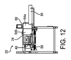
複数のコイル状の帯を製造し、それらをコイル状の形に保持するシステム20の工程を図6から図14に示す。図6は、荷敷きの帯が巻回されチューブ24内に保持されるように移動させられる前の、コイラ30とチューブ24を備えるシステム20を示す。図7は、製造されてチューブ24の第1端部58に配置される1番目のコイル状の荷敷きの帯64aと、コイル状の帯64aを移動する前の巻回位置にあるプッシャ48を示す。図8は、1番目のコイル状の帯64aがプッシャ48によりチューブ24の第1端部58から第2端部60へ向けて排出方向に移動させられた後のシステム20を示す。プッシャ48は巻回位置から離れた移動後位置にある。
The process of
図9は、1番目のコイル状の帯64aを移動させた後に巻回位置に戻ったプッシャ48を示す。図10においては、2番目に製造されたコイル状の帯64bがチューブ24の第1端部58に位置し、1番目のコイル状の帯64aがチューブ24の第2端部60に保持されている。プッシャ48は巻回位置にある。図11は、2番目のコイル状の帯64bが、プッシャ48により第1端部58から第2端部60へ向けて移動させられ、1番目のコイル状の帯64aに隣接するようになった後のシステム20を示す。プッシャ48は移動後位置にある。2番目のコイル状の帯64bは、チューブ24内において1番目のコイル状の帯64aをさらに少し排出方向へ押す。図12は、2番目のコイル状の帯64bを移動させた後に巻回位置に戻されたプッシャ48を示す。図13は、プッシャ48により移動させられてチューブ24により保持される3番目のコイル状の帯64cを示す。図14は、製造されてプッシャ48によりチューブ24の内部へ移動させられてコイル状の形に保持される4番目および5番目のコイル状の荷敷きの帯64d、64eを示す。
FIG. 9 shows the
システム20は、複数の荷敷きのコイル状の帯を製造し、それらをコイル状の形に保持することを容易にする複数の制御要素を備えてもよい。図1に示すように、制御要素は、チューブ24に関連付けられた少なくとも1つのセンサ66を備える。少なくとも1つのセンサ66は、荷敷きのコイル状の帯がチューブ24の内部へと軸方向に移動させられたこと、又は、所定の数のコイル状の帯がチューブ24の内部に保持されていることを検知するセンサを含んでもよい。少なくとも1つのセンサ66は、コイル状の帯がチューブ24から取り出されたことを検知するセンサを含んでもよい。少なくとも1つのセンサ66は、変換機コントローラ68とコイラコントローラ70のうち少なくとも1つと通信してもよい。変換機コントローラ68に接続されている場合、チューブ24が荷敷きのコイル状の帯を受け取る容量を有する旨をセンサ66が示すとき、変換機コントローラ68が変換機26を作動させてもよい。センサ66がコイラコントローラ70に接続されている場合には、チューブ24が荷敷きのコイル状の帯を受け入れる容量を有するという旨をセンサ66が示すときに、コイラコントローラ70がコイラ30を作動させてもよい。システム20の制御要素は、システム20に対して、チューブ24の予め定められた容量に基づき、複数のコイル状の帯を製造し、コイル状の形に保持することを許可する。
図3に示すように、制御要素はさらに、荷敷きの帯がコイラ30によって巻回されたことを検知するセンサ72を備えてもよい。帯が巻回されたことをセンサ72が示すことに応答して、前述したようにプッシャ48が作動させられてもよい。プッシャアクチュエータ52がセンサ72に応答してプッシャ48を作動させて、荷敷きのコイル状の帯を排出方向へ移動させてもよい。
As shown in FIG. 3, the control element may further comprise a
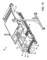
システム20が作動していない場合又は休止中の場合、典型的には、チューブ24はその作動位置とは離れたサービス位置をとり、通常はチューブ24の位置のためにアクセスできないこともあるシステム20のコイラ30その他の構成部品のメンテナンスを可能とする。図2では、チューブ24が作動位置にあってチューブ24の第1端部58がコイラ30を取り囲み、コイラ30へのアクセスを防止している。図3及び図4では、チューブ24が作動位置から離されたサービス位置にあり、第1端部58によるコイラ30の取り囲みが解除されているので、コイラ30へのアクセスが可能である。図2〜4に示すようにチューブ24は、作動位置とそこから離されたサービス位置との間をチューブスライド74に沿った動きにより移動可能であり、チューブスライド74は排出方向へ伸びていてもよい。
When the
図示されるチューブスライド74は、図2及び図3に最もよく示されるように、チューブ24の外側に位置し、巻回軸と平行である。チューブスライド74は、固定トラック74aと、チューブ24の外面に固定される可動トラック74bとを備える。可動トラック74bは固定トラック74aに対して移動可能であり、チューブ24をコイラ30から移動させる。図2に示すように、チューブスライド74は、システム20の作動中、もしくはシステム20の輸送中に、可動トラック74bが固定トラック74aに対して移動すること防止するスライドロック74cを備えてもよい。図3に示すように、スライドロック74cは、可動トラック74bとチューブ24がコイラ30から離れて軸方向に移動できるようアンロック(解除)されてもよい。チューブスライド74はトラック76によって支持されてもよく、トラック76はプッシャスライド54も支持し、プッシャスライド54に沿ってプッシャ48はその巻回位置と移動後位置の間を移動し、それによって、完成した荷敷きのコイル状の帯を移動させる。トラック76は、プッシャスライド54及びチューブスライド74を支持し、それによりプッシャ48及びチューブ24が、それぞれの互いに独立したスライドに沿って移動できるように構成される。
The illustrated
さらに図5を参照し、システム20は、チューブ24がチューブスライド74に沿って作動位置から移動させられる場合又はチューブ24が作動位置から離されたサービス位置にある場合に、コイラ30の移動を防止するコイラアームロック78を備えてもよい。システム20は、メンテナンス作業又はアーム交換のためにコイラアームロック78をアンロックしてコイラ30のアームを移動可能とするため、チューブ24の第1端部58が作動位置にないことを検知するセンサ80を備えてもよい。センサ80はまた、プッシャ48がコイラ30から離れた移動後位置にあることを検知するセンサを備えてもよい。センサ80が、チューブ24とプッシャ48とがコイラ30から離されていることを示すと、コイラアームロック78がアンロックされてコイラ30のアームの移動が可能とされる。
Still referring to FIG. 5, the
このように、コイラアームロック78は追加的なロック機能を提供することにより、従来のコイラアームロックを改良するものである。従来のコイラアームロックは、コイラフォーク44が確実にロック位置にあるようにするために使用されるものであり、いつでもアンロックすることが可能であった。本発明によるコイラアームロック78は、チューブ24がコイラ30から離されていることをセンサ80が示すまでアンロックされない。システム20はさらに従来のコイラアームロックに類似する補助コイラアームロック81を備えてもよい。これにより、チューブ24がコイラ30から離されていることをセンサ80が示すと、コイラアームロック78は自動的にアンロックされ、さらに補助コイラアームロック81は従前の方法でアンロックされなければならないので、バックアップとなる。
Thus,
メンテナンス作業時とは別に、システム20の搬送時にもシステム20はロックされ得る。図15に示されるように、システム20の搬送時にはチューブ24の第1端部58がコイラ30を取り囲みコイラ30へのアクセスを防止するように、チューブ24が配置される。コイラアームロック78のロックにより、コイラ30の移動も防止される。プッシャ48はその巻回位置にあり、その移動後位置へは移動できない。可動トラック74bと、可動トラック74bに固定されているチューブ24の両方が固定トラック74aに対して移動できないように、チューブスライド74のスライドロック74cはロックされる。変換機26はチューブガード82を備えてもよい。図4に最もよく示されるように、チューブ24が移動後位置にあるとき、第1端部58はチューブ24とともに移動する。ただしチューブガード82はチューブ24とともには移動せず、元の位置にとどまる。コイラ30が荷敷きの帯を巻回するために回転する間、チューブガード82はチューブ24と連携してコイラ30へのアクセスを防止する。
The
図2〜4及び図6〜14に示すシステム20の例では、システム20は、コイル状の帯がチューブ24を出た後さらに荷敷きのコイル状の帯をコイル状の形に保持するため、チューブ24の第2端部60に隣接して、そこから排出方向に伸びる任意のコイルトレイ84をさらに備えてもよい。コイルトレイ84は、システム20の取付け部品に装着されチューブ24の長手方向軸と平行に伸びるブラケット86上で支持される。コイルトレイ84は、チューブ24内のコイル状の帯の数がチューブ24の保持容量を超えたことによってチューブ24から押し出されたコイル状の帯を受け取るために使用されてもよい。コイルトレイ84は半円形であり、チューブ24とほぼ同一の直径を有し、コイルトレイ84上に支持されるコイル状の帯を部分的に取り囲む。コイルトレイ84はコイル状の帯が取り出されるまで、複数のコイル状の帯を保持してもよい。チューブ24に加えてコイルトレイ84を使用する利点は、コイル状の帯がチューブ24を出た後もなお、接着剤、テープ、ステープルその他の固定手段を必要とすることなくコイル状の帯をコイル状の形に保持するのにコイルトレイ84が役立つとともに、コイル状の帯を取り出すためのアクセスがコイルトレイ84によりさらに容易になることである。
In the
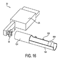
図16に示すように、例としてのコイルトレイ184は、チューブ124と一体の延長部分として形成される。コイルトレイ184により、チューブ124からコイル状の帯を取り出す際のアクセスがさらに容易となる。これまでに説明したように、図示されるチューブ124をシステム20において使用してもよい。チューブ124はセンサ166を備えてもよい。センサ166は、チューブ124内又はチューブ124のコイルトレイ部分184内にあるコイル状の帯188の位置を検知する。センサ166は、チューブ124からコイル状の帯188が取り出されたことを検知してもよい。センサ166は、変換機26及びコイラ30のうち少なくとも1つと通信してもよく、それによりセンサ166がチューブ124又はコイルトレイ部分184のうち1つが次のコイル状の帯を受け取る容量を有することを示す場合、変換機26及びコイラ30が作動させられてもよい。
As shown in FIG. 16, the
本発明はさらに、コイル状の荷敷きを製造する方法を提供するものであり、方法は(1)巻回軸の周りに荷敷きの帯を巻回する工程と、(2)荷敷きのコイル状の帯をチューブ内へ軸方向に移動させて、荷敷きのコイル状の帯をコイル状の形に保持する工程とを含む。方法はさらに(3)荷敷きのコイル状の帯が軸方向に移動させられたことを検知する工程と、(4)チューブ内に所定の数の荷敷きのコイル状の帯が保持されていることを検知する工程と、(5)荷敷きのコイル状の帯がチューブから取り出されたことを検知する工程とを含んでもよい。方法はさらに(6)荷敷きのコイル状の帯がチューブから取り出されたことを伝える信号に応じて、荷敷きの帯を巻回する工程を含んでもよい。方法はさらに(7)シートストック材を荷敷きの帯に変換するように作動する変換機を制御する工程と、(8)チューブが、荷敷きのコイル状の帯を受け取る容量を有することを示す信号に応じて、荷敷きの帯を巻回することを制御する工程とを含んでもよい。 The invention further provides a method of manufacturing a coiled dunnage, the method comprising: (1) winding a dunnage band around a winding axis; and (2) a dunnage coil. Moving the strips axially into the tube to retain the coiled strips of the dunnage in a coiled shape. The method further includes (3) a step of detecting that the coiled band of the dunnage has been moved in the axial direction, and (4) holding a predetermined number of the coiled band of the dunnage in the tube. It may include a step of detecting the fact, and a step (5) of detecting that the coiled strip of the dunnage is taken out from the tube. The method may further include (6) winding the dunnage strip in response to a signal that the coiled strip of dunnage has been removed from the tube. The method further comprises (7) controlling the converter operating to convert the sheet stock material into a dunnage strip, and (8) indicating that the tube has a capacity to receive the dunnage coiled strip. Controlling the winding of the dunnage band in response to the signal.
要約すれば、本発明は荷敷きのコイル状の帯を製造する荷敷き製造システム20であって、帯状の荷敷き29の供給部と、供給部と隣接するコイラ30であって、帯状の荷敷き29の帯を巻回してコイル状の形を有するコイルにするために巻回軸周りに回転可能であるコイラ30と、巻回軸に揃えられるチューブ24とを備える。チューブ24は、コイラ30からのコイルを巻回軸と平行な排出方向に受け取る内径寸法を有する。チューブ24は少なくとも1つの荷敷きのコイル状の帯を、それがチューブ24から取り出されるまでそのコイル状の形に保持可能である。
In summary, the present invention is a
本発明を複数の実施形態により図示及び説明したが、本明細書及び添付された図面を読み理解することにより、当業者は、等価的な変更及び修正に想到するだろう。特に上記の要素(構成部品、アセンブリ、デバイス、構成等)により実施される様々な機能に関して、そのような要素を説明するために使用された用語(「手段」の言及を含む)は、別段の表示がない限り、本明細書中で例示された本発明の例となる実施形態において、機能を実行する開示された構造と構造的に等価でなくとも、説明された要素の特定の機能を実行する(即ち、機能的に等価である)あらゆる要素に相当することを意図している。さらに、本発明の特定の特徴が、幾つかの示された実施形態の1つのみに関して説明された場合もあるが、そのような特徴は他の実施形態の1つ又は複数の特徴と組み合わせることも可能であり、そのような組み合わせは所与の又は特定の応用において望ましいか又は有利な場合がある。 While the invention has been illustrated and described by way of several embodiments, those skilled in the art will perceive equivalent changes and modifications upon reading and understanding the specification and the accompanying drawings. The terminology used to describe any such element (including reference to "means") is specifically defined as regards the various functions performed by that element (component, assembly, device, configuration, etc.) above. Unless indicated to the contrary, in the exemplary embodiments of the invention illustrated herein, certain functions of the elements described are performed, even if they are not structurally equivalent to the disclosed structures performing the functions. It is intended to correspond to any element (i.e., functionally equivalent). Furthermore, although certain features of the invention may have been described with respect to only one of the several illustrated embodiments, such feature may be combined with one or more of the features of other embodiments. Are also possible, and such combinations may be desirable or advantageous in a given or particular application.
Claims (29)
帯状の荷敷きの供給部と、
前記供給部に隣接し、前記供給部からの前記荷敷きの帯を巻回してコイル状の形にするために巻回軸周りに回転可能であるコイラと、
前記巻回軸に揃えられ、前記コイラからのコイルを前記巻回軸と平行な排出方向に受け取るための内径寸法を有し、少なくとも1つの荷敷きのコイル状の帯を受け取りコイル状の形に保持することが可能なチューブとを備える、システム。 A system for manufacturing a coiled strip of dunnage,
A strip-shaped mattress supply section,
A coiler that is adjacent to the supply unit and is rotatable around a winding axis to wind the dunnage strip from the supply unit into a coiled shape,
Aligned with the winding axis, having an inner diameter dimension for receiving the coil from the coiler in the discharge direction parallel to the winding axis, and receiving at least one coiled band of the dunnage into a coiled shape. A tube capable of holding.
前記荷敷きの帯が巻回されると前記プッシャが作動される、請求項4に記載のシステム。 Further comprising at least one sensor for detecting that the dunnage strip has been wound,
The system of claim 4 , wherein the pusher is activated when the dunnage strip is wound.
前記プッシャが前記巻回位置と前記移動後位置の間を前記プッシャスライドに沿って移動する、請求項3〜7のいずれか一項に記載のシステム。 Further comprising a pusher slide located outside the tube,
The pusher is moved along between the position after the movement and the winding position on the pusher slide, according to any one of claims 3-7 system.
前記変換機は帯状の前記荷敷きの帯を前記コイラに向けて下流方向へ送り出す出口を有する、請求項1〜12のいずれか一項に記載のシステム。 Further comprising a converter operable to convert sheet stock material into a supply of said dunnage strip,
The converter has an outlet for feeding the strip of flooring the load of the strip in the downstream direction toward the coiler, as claimed in any one of claims 1 to 1 2 system.
帯状の荷敷きを供給する手段と、
巻回軸周りに前記帯状の荷敷きの帯を巻回する手段と、
前記巻回する手段からの前記荷敷きのコイル状の帯を移動させる手段と、
前記荷敷きのコイル状の帯をコイル状の形に保持する手段とを備え、
前記保持する手段は、前記巻回軸に揃えられ、前記巻回する手段からのコイルを前記巻回軸と平行な排出方向に受け取る内径寸法を有するチューブを備え、
前記チューブは少なくとも1つの前記荷敷きのコイル状の帯を受け取りコイル状の形に保持する、システム。 A system for manufacturing a coiled strip of dunnage,
Means for supplying a strip of dunnage,
A means for winding the belt-shaped dread belt around the winding axis,
Means for moving the coiled strip of the dunnage from the winding means,
A means for holding the coiled strip of the dunnage in a coiled shape ,
The holding means comprises a tube having an inner diameter dimension that is aligned with the winding axis and receives the coil from the winding means in a discharge direction parallel to the winding axis.
The system wherein the tube receives and holds in coiled form at least one coiled band of the dunnage .
巻回軸周りに荷敷きの帯を巻回する工程と、
前記荷敷きのコイル状の帯を前記チューブの内部へ軸方向に移動させ、前記荷敷きのコイル状の帯をコイル状の形に保持する工程とを備える、コイル状の荷敷きを製造する方法。 A method of manufacturing a coiled dunnage using the system of claim 1 or claim 19,
A step of winding a dunnage band around the winding axis,
Wherein said the dunnage coiled strip is moved inside to the axial direction of the tube, a coiled strip of flooring the load and a step of holding the shape of the coiled, to produce a coiled dunnage .
Applications Claiming Priority (3)
| Application Number | Priority Date | Filing Date | Title |
|---|---|---|---|
| US201562245648P | 2015-10-23 | 2015-10-23 | |
| US62/245,648 | 2015-10-23 | ||
| PCT/US2016/058462 WO2017070670A1 (en) | 2015-10-23 | 2016-10-24 | Dunnage system and method using a coil accumulator |
Publications (4)
| Publication Number | Publication Date |
|---|---|
| JP2018531199A JP2018531199A (en) | 2018-10-25 |
| JP2018531199A6 JP2018531199A6 (en) | 2018-12-13 |
| JP2018531199A5 JP2018531199A5 (en) | 2018-12-13 |
| JP6683810B2 true JP6683810B2 (en) | 2020-04-22 |
Family
ID=57219068
Family Applications (1)
| Application Number | Title | Priority Date | Filing Date |
|---|---|---|---|
| JP2018521071A Active JP6683810B2 (en) | 2015-10-23 | 2016-10-24 | DAPPING SYSTEM AND METHOD USING COIL STORAGE DEVICE |
Country Status (7)
| Country | Link |
|---|---|
| US (1) | US10864696B2 (en) |
| EP (1) | EP3365256B1 (en) |
| JP (1) | JP6683810B2 (en) |
| CN (1) | CN108137256B (en) |
| BR (1) | BR112018007951B1 (en) |
| CA (1) | CA3002714C (en) |
| WO (1) | WO2017070670A1 (en) |
Families Citing this family (4)
| Publication number | Priority date | Publication date | Assignee | Title |
|---|---|---|---|---|
| DE102018107156A1 (en) * | 2018-03-26 | 2019-09-26 | Sprick Gmbh Bielefelder Papier- Und Wellpappenwerke & Co. | Winding device and padding winding system |
| DE102018007549A1 (en) * | 2018-09-24 | 2020-03-26 | Sprick Gmbh Bielefelder Papier- Und Wellpappenwerke & Co. | Drive mechanism for a packaging material strand winder, packaging material strand winder, wrapped packaging material cushion and method for producing the same |
| JP2024535494A (en) | 2021-10-01 | 2024-09-30 | クーパー,クレイトン | Dunnage Manufacturing System |
| CN114348724B (en) * | 2022-01-19 | 2024-06-04 | 东台市东强纺织有限公司 | Quick-release type cloth rolling and cutting device for cloth rolling machine |
Family Cites Families (18)
| Publication number | Priority date | Publication date | Assignee | Title |
|---|---|---|---|---|
| US3613522A (en) * | 1969-09-12 | 1971-10-19 | Arpax Co | Method of producing cushioning dunnage |
| US4237776A (en) * | 1978-06-02 | 1980-12-09 | Ranpak Corporation | Cushioning dunnage mechanism |
| US5064132A (en) * | 1988-04-12 | 1991-11-12 | Merz Wolf D | Device for taking-up a width of flexible material, paper in particular, to form a roll |
| US5257492A (en) | 1991-04-05 | 1993-11-02 | Patriot Packaging Corporation | Dunnage, method and apparatus for making, and package using same |
| JP2631584B2 (en) * | 1991-06-28 | 1997-07-16 | 大日本スクリーン製造株式会社 | Long film storage device |
| US5487717A (en) * | 1993-05-21 | 1996-01-30 | Ranpak Corp. | Dispensing table for a cushioning conversion machine |
| US6168559B1 (en) * | 1993-11-19 | 2001-01-02 | Ranpak Corp. | Cushioning conversion machine including a pad-transferring assembly |
| JPH08267137A (en) * | 1995-03-29 | 1996-10-15 | Kawasaki Steel Corp | Upender of strip coil |
| US5813967A (en) * | 1997-02-25 | 1998-09-29 | Ranpak Corp. | Cushioning conversion machine with guide roller, and method |
| CN1265628A (en) * | 1997-06-11 | 2000-09-06 | 兰帕克公司 | Cushioning conversion system and method |
| US6090033A (en) * | 1997-09-02 | 2000-07-18 | Ranpak Corp. | Cushioning conversion machine for producing U-shape pads |
| WO1999021702A2 (en) * | 1997-10-27 | 1999-05-06 | Ranpak Corp. | Cushioning conversion system and method for making a coil of cushioning product |
| US6174273B1 (en) * | 1998-12-18 | 2001-01-16 | Ranpak Corp. | Cushioning conversion machine with tension control |
| WO2004041527A1 (en) * | 2002-11-05 | 2004-05-21 | Ranpak Corp. | System and method for making a coiled strip of dunnage |
| EP2204325B1 (en) * | 2004-11-05 | 2012-03-07 | Ranpak Corp. | Automated dunnage filling system and method |
| WO2011143635A2 (en) * | 2010-05-13 | 2011-11-17 | Nuevopak International Limited | Apparatus, systems and methods for producing cushioning material |
| US20110308974A1 (en) * | 2010-06-22 | 2011-12-22 | Curtin Paul M | Packaged, Wrapped, Cylindrically Rolled Moisture-Sensitive Film and Method of Making the Same |
| CA2900986C (en) * | 2013-02-12 | 2021-02-16 | Ranpak Corp. | Dunnage system with coiler, automated taping and ejecting apparatus and method |
-
2016
- 2016-10-24 BR BR112018007951-0A patent/BR112018007951B1/en active IP Right Grant
- 2016-10-24 WO PCT/US2016/058462 patent/WO2017070670A1/en active Application Filing
- 2016-10-24 JP JP2018521071A patent/JP6683810B2/en active Active
- 2016-10-24 US US15/768,163 patent/US10864696B2/en active Active
- 2016-10-24 CA CA3002714A patent/CA3002714C/en active Active
- 2016-10-24 CN CN201680061883.4A patent/CN108137256B/en active Active
- 2016-10-24 EP EP16788931.0A patent/EP3365256B1/en active Active
Also Published As
| Publication number | Publication date |
|---|---|
| EP3365256B1 (en) | 2020-12-02 |
| EP3365256A1 (en) | 2018-08-29 |
| CN108137256B (en) | 2020-12-15 |
| JP2018531199A (en) | 2018-10-25 |
| CA3002714A1 (en) | 2017-04-27 |
| US10864696B2 (en) | 2020-12-15 |
| WO2017070670A1 (en) | 2017-04-27 |
| BR112018007951A2 (en) | 2018-10-30 |
| CA3002714C (en) | 2022-02-15 |
| US20180304571A1 (en) | 2018-10-25 |
| CN108137256A (en) | 2018-06-08 |
| BR112018007951B1 (en) | 2023-01-10 |
Similar Documents
| Publication | Publication Date | Title |
|---|---|---|
| JP6683810B2 (en) | DAPPING SYSTEM AND METHOD USING COIL STORAGE DEVICE | |
| JP6776300B2 (en) | Cushioning system with take-up device, automatic taping device, and discharge device, and method | |
| RU2744712C2 (en) | Advanced machine and a method of stretch film packaging of products supplied in blocks or separately | |
| JP6126614B2 (en) | Elevated conversion machine with delivery guidance | |
| JP2018531199A6 (en) | Packing system and method using coil storage device | |
| US11753197B2 (en) | Packaging station and method of operating a packaging station | |
| JP2022518915A (en) | Coilers and methods for dunnage converters | |
| JPS5820610A (en) | Beltlike packing packer for article to be packed | |
| JP6858718B2 (en) | Improved tubular elements for smoking items | |
| US6152670A (en) | Storage arrangement for cores of a papermaking machine | |
| JP2024535494A (en) | Dunnage Manufacturing System | |
| WO2006122568A1 (en) | Apparatus and method for cable winding apparatus | |
| CN114126979A (en) | Application of a packaging unit for strapping bands | |
| WO2016044863A2 (en) | Packaging method | |
| EP3478614A1 (en) | Apparatus and method for making a coil of dunnage | |
| CN112654570A (en) | Method for producing a roll of fabric and roll thus produced |
Legal Events
| Date | Code | Title | Description |
|---|---|---|---|
| A521 | Request for written amendment filed |
Free format text: JAPANESE INTERMEDIATE CODE: A523 Effective date: 20181101 |
|
| A621 | Written request for application examination |
Free format text: JAPANESE INTERMEDIATE CODE: A621 Effective date: 20181101 |
|
| A977 | Report on retrieval |
Free format text: JAPANESE INTERMEDIATE CODE: A971007 Effective date: 20191004 |
|
| A131 | Notification of reasons for refusal |
Free format text: JAPANESE INTERMEDIATE CODE: A131 Effective date: 20191015 |
|
| A521 | Request for written amendment filed |
Free format text: JAPANESE INTERMEDIATE CODE: A523 Effective date: 20200114 |
|
| TRDD | Decision of grant or rejection written | ||
| A01 | Written decision to grant a patent or to grant a registration (utility model) |
Free format text: JAPANESE INTERMEDIATE CODE: A01 Effective date: 20200310 |
|
| A61 | First payment of annual fees (during grant procedure) |
Free format text: JAPANESE INTERMEDIATE CODE: A61 Effective date: 20200326 |
|
| R150 | Certificate of patent or registration of utility model |
Ref document number: 6683810 Country of ref document: JP Free format text: JAPANESE INTERMEDIATE CODE: R150 |
|
| R250 | Receipt of annual fees |
Free format text: JAPANESE INTERMEDIATE CODE: R250 |
|
| R250 | Receipt of annual fees |
Free format text: JAPANESE INTERMEDIATE CODE: R250 |