JP6683403B2 - Smoking articles and mouthpieces for smoking articles - Google Patents
Smoking articles and mouthpieces for smoking articles Download PDFInfo
- Publication number
- JP6683403B2 JP6683403B2 JP2017543350A JP2017543350A JP6683403B2 JP 6683403 B2 JP6683403 B2 JP 6683403B2 JP 2017543350 A JP2017543350 A JP 2017543350A JP 2017543350 A JP2017543350 A JP 2017543350A JP 6683403 B2 JP6683403 B2 JP 6683403B2
- Authority
- JP
- Japan
- Prior art keywords
- cylindrical element
- recess
- mouthpiece
- smoking article
- section
- Prior art date
- Legal status (The legal status is an assumption and is not a legal conclusion. Google has not performed a legal analysis and makes no representation as to the accuracy of the status listed.)
- Active
Links
- 230000000391 smoking effect Effects 0.000 title claims description 118
- 239000000463 material Substances 0.000 claims description 55
- 239000000654 additive Substances 0.000 claims description 28
- 230000000996 additive effect Effects 0.000 claims description 19
- 239000000779 smoke Substances 0.000 claims description 16
- 239000000835 fiber Substances 0.000 claims description 9
- 238000004049 embossing Methods 0.000 claims description 7
- 239000000853 adhesive Substances 0.000 claims description 6
- 230000001070 adhesive effect Effects 0.000 claims description 6
- 239000003463 adsorbent Substances 0.000 claims description 5
- 239000002775 capsule Substances 0.000 claims description 5
- 229920003023 plastic Polymers 0.000 claims description 5
- 239000004033 plastic Substances 0.000 claims description 5
- 235000013311 vegetables Nutrition 0.000 claims description 3
- 239000000443 aerosol Substances 0.000 description 21
- 241000208125 Nicotiana Species 0.000 description 12
- 235000002637 Nicotiana tabacum Nutrition 0.000 description 12
- 235000019504 cigarettes Nutrition 0.000 description 12
- 239000011248 coating agent Substances 0.000 description 10
- 238000000576 coating method Methods 0.000 description 10
- 238000000034 method Methods 0.000 description 10
- OKTJSMMVPCPJKN-UHFFFAOYSA-N Carbon Chemical compound [C] OKTJSMMVPCPJKN-UHFFFAOYSA-N 0.000 description 9
- 229920002301 cellulose acetate Polymers 0.000 description 7
- 238000010276 construction Methods 0.000 description 6
- 238000003780 insertion Methods 0.000 description 5
- 230000037431 insertion Effects 0.000 description 5
- 239000004372 Polyvinyl alcohol Substances 0.000 description 4
- 239000003570 air Substances 0.000 description 4
- 239000003205 fragrance Substances 0.000 description 4
- 239000004014 plasticizer Substances 0.000 description 4
- 229920001610 polycaprolactone Polymers 0.000 description 4
- 239000004632 polycaprolactone Substances 0.000 description 4
- 229920002451 polyvinyl alcohol Polymers 0.000 description 4
- NOOLISFMXDJSKH-UTLUCORTSA-N (+)-Neomenthol Chemical compound CC(C)[C@@H]1CC[C@@H](C)C[C@@H]1O NOOLISFMXDJSKH-UTLUCORTSA-N 0.000 description 3
- NOOLISFMXDJSKH-UHFFFAOYSA-N DL-menthol Natural products CC(C)C1CCC(C)CC1O NOOLISFMXDJSKH-UHFFFAOYSA-N 0.000 description 3
- 230000000694 effects Effects 0.000 description 3
- 229940041616 menthol Drugs 0.000 description 3
- URAYPUMNDPQOKB-UHFFFAOYSA-N triacetin Chemical compound CC(=O)OCC(OC(C)=O)COC(C)=O URAYPUMNDPQOKB-UHFFFAOYSA-N 0.000 description 3
- SNICXCGAKADSCV-JTQLQIEISA-N (-)-Nicotine Chemical compound CN1CCC[C@H]1C1=CC=CN=C1 SNICXCGAKADSCV-JTQLQIEISA-N 0.000 description 2
- QTBSBXVTEAMEQO-UHFFFAOYSA-M Acetate Chemical compound CC([O-])=O QTBSBXVTEAMEQO-UHFFFAOYSA-M 0.000 description 2
- 229920000742 Cotton Polymers 0.000 description 2
- 240000009023 Myrrhis odorata Species 0.000 description 2
- 235000007265 Myrrhis odorata Nutrition 0.000 description 2
- 235000012550 Pimpinella anisum Nutrition 0.000 description 2
- 229920002472 Starch Polymers 0.000 description 2
- 229920003232 aliphatic polyester Polymers 0.000 description 2
- OPZZWWFHZYZBRU-UHFFFAOYSA-N butanedioic acid;butane-1,1-diol Chemical compound CCCC(O)O.OC(=O)CCC(O)=O OPZZWWFHZYZBRU-UHFFFAOYSA-N 0.000 description 2
- 238000006073 displacement reaction Methods 0.000 description 2
- 239000003571 electronic cigarette Substances 0.000 description 2
- 239000002657 fibrous material Substances 0.000 description 2
- 238000001914 filtration Methods 0.000 description 2
- 239000000796 flavoring agent Substances 0.000 description 2
- 235000019634 flavors Nutrition 0.000 description 2
- 150000004676 glycans Chemical class 0.000 description 2
- 235000013773 glyceryl triacetate Nutrition 0.000 description 2
- 229960002715 nicotine Drugs 0.000 description 2
- SNICXCGAKADSCV-UHFFFAOYSA-N nicotine Natural products CN1CCCC1C1=CC=CN=C1 SNICXCGAKADSCV-UHFFFAOYSA-N 0.000 description 2
- 239000002245 particle Substances 0.000 description 2
- 229920001896 polybutyrate Polymers 0.000 description 2
- 239000004626 polylactic acid Substances 0.000 description 2
- 229920000642 polymer Polymers 0.000 description 2
- 229920001282 polysaccharide Polymers 0.000 description 2
- 239000005017 polysaccharide Substances 0.000 description 2
- 239000008107 starch Substances 0.000 description 2
- 235000019698 starch Nutrition 0.000 description 2
- 125000000383 tetramethylene group Chemical group [H]C([H])([*:1])C([H])([H])C([H])([H])C([H])([H])[*:2] 0.000 description 2
- 229960002622 triacetin Drugs 0.000 description 2
- 240000007087 Apium graveolens Species 0.000 description 1
- 235000015849 Apium graveolens Dulce Group Nutrition 0.000 description 1
- 235000010591 Appio Nutrition 0.000 description 1
- 240000007436 Cananga odorata Species 0.000 description 1
- 240000004160 Capsicum annuum Species 0.000 description 1
- 235000005747 Carum carvi Nutrition 0.000 description 1
- 240000000467 Carum carvi Species 0.000 description 1
- 240000003538 Chamaemelum nobile Species 0.000 description 1
- 235000007866 Chamaemelum nobile Nutrition 0.000 description 1
- 244000037364 Cinnamomum aromaticum Species 0.000 description 1
- 235000014489 Cinnamomum aromaticum Nutrition 0.000 description 1
- 244000223760 Cinnamomum zeylanicum Species 0.000 description 1
- 235000002787 Coriandrum sativum Nutrition 0.000 description 1
- 244000018436 Coriandrum sativum Species 0.000 description 1
- 240000002943 Elettaria cardamomum Species 0.000 description 1
- 241000196324 Embryophyta Species 0.000 description 1
- 240000006927 Foeniculum vulgare Species 0.000 description 1
- 235000004204 Foeniculum vulgare Nutrition 0.000 description 1
- 240000001238 Gaultheria procumbens Species 0.000 description 1
- 235000007297 Gaultheria procumbens Nutrition 0.000 description 1
- 241000208152 Geranium Species 0.000 description 1
- 240000004670 Glycyrrhiza echinata Species 0.000 description 1
- 235000001453 Glycyrrhiza echinata Nutrition 0.000 description 1
- 235000006200 Glycyrrhiza glabra Nutrition 0.000 description 1
- 235000017382 Glycyrrhiza lepidota Nutrition 0.000 description 1
- 244000267823 Hydrangea macrophylla Species 0.000 description 1
- 235000014486 Hydrangea macrophylla Nutrition 0.000 description 1
- 235000010254 Jasminum officinale Nutrition 0.000 description 1
- 240000005385 Jasminum sambac Species 0.000 description 1
- 244000178870 Lavandula angustifolia Species 0.000 description 1
- 235000010663 Lavandula angustifolia Nutrition 0.000 description 1
- 241000218378 Magnolia Species 0.000 description 1
- 235000007232 Matricaria chamomilla Nutrition 0.000 description 1
- 235000006679 Mentha X verticillata Nutrition 0.000 description 1
- 235000014749 Mentha crispa Nutrition 0.000 description 1
- 244000246386 Mentha pulegium Species 0.000 description 1
- 235000016257 Mentha pulegium Nutrition 0.000 description 1
- 244000078639 Mentha spicata Species 0.000 description 1
- 235000002899 Mentha suaveolens Nutrition 0.000 description 1
- 235000004357 Mentha x piperita Nutrition 0.000 description 1
- 235000001636 Mentha x rotundifolia Nutrition 0.000 description 1
- 235000016639 Syzygium aromaticum Nutrition 0.000 description 1
- 244000223014 Syzygium aromaticum Species 0.000 description 1
- 235000009499 Vanilla fragrans Nutrition 0.000 description 1
- 244000263375 Vanilla tahitensis Species 0.000 description 1
- 235000012036 Vanilla tahitensis Nutrition 0.000 description 1
- 235000006886 Zingiber officinale Nutrition 0.000 description 1
- 244000273928 Zingiber officinale Species 0.000 description 1
- 239000012080 ambient air Substances 0.000 description 1
- WHGYBXFWUBPSRW-FOUAGVGXSA-N beta-cyclodextrin Chemical compound OC[C@H]([C@H]([C@@H]([C@H]1O)O)O[C@H]2O[C@@H]([C@@H](O[C@H]3O[C@H](CO)[C@H]([C@@H]([C@H]3O)O)O[C@H]3O[C@H](CO)[C@H]([C@@H]([C@H]3O)O)O[C@H]3O[C@H](CO)[C@H]([C@@H]([C@H]3O)O)O[C@H]3O[C@H](CO)[C@H]([C@@H]([C@H]3O)O)O3)[C@H](O)[C@H]2O)CO)O[C@@H]1O[C@H]1[C@H](O)[C@@H](O)[C@@H]3O[C@@H]1CO WHGYBXFWUBPSRW-FOUAGVGXSA-N 0.000 description 1
- 229910052799 carbon Inorganic materials 0.000 description 1
- 235000005300 cardamomo Nutrition 0.000 description 1
- 235000019506 cigar Nutrition 0.000 description 1
- 235000017803 cinnamon Nutrition 0.000 description 1
- 239000000470 constituent Substances 0.000 description 1
- 238000010586 diagram Methods 0.000 description 1
- 239000005454 flavour additive Substances 0.000 description 1
- 235000013355 food flavoring agent Nutrition 0.000 description 1
- 235000008397 ginger Nutrition 0.000 description 1
- 239000001087 glyceryl triacetate Substances 0.000 description 1
- 235000008216 herbs Nutrition 0.000 description 1
- 235000001050 hortel pimenta Nutrition 0.000 description 1
- 239000004922 lacquer Substances 0.000 description 1
- 239000001102 lavandula vera Substances 0.000 description 1
- 235000018219 lavender Nutrition 0.000 description 1
- 229940010454 licorice Drugs 0.000 description 1
- 239000007788 liquid Substances 0.000 description 1
- 238000004519 manufacturing process Methods 0.000 description 1
- OSWPMRLSEDHDFF-UHFFFAOYSA-N methyl salicylate Chemical compound COC(=O)C1=CC=CC=C1O OSWPMRLSEDHDFF-UHFFFAOYSA-N 0.000 description 1
- 238000012986 modification Methods 0.000 description 1
- 230000004048 modification Effects 0.000 description 1
- 239000012778 molding material Substances 0.000 description 1
- 239000002304 perfume Substances 0.000 description 1
- 230000000704 physical effect Effects 0.000 description 1
- 239000004800 polyvinyl chloride Substances 0.000 description 1
- 229920000915 polyvinyl chloride Polymers 0.000 description 1
- 238000002407 reforming Methods 0.000 description 1
- 235000002020 sage Nutrition 0.000 description 1
- 230000001953 sensory effect Effects 0.000 description 1
- 239000002356 single layer Substances 0.000 description 1
- 239000002966 varnish Substances 0.000 description 1
Images


Classifications
-
- A—HUMAN NECESSITIES
- A24—TOBACCO; CIGARS; CIGARETTES; SIMULATED SMOKING DEVICES; SMOKERS' REQUISITES
- A24D—CIGARS; CIGARETTES; TOBACCO SMOKE FILTERS; MOUTHPIECES FOR CIGARS OR CIGARETTES; MANUFACTURE OF TOBACCO SMOKE FILTERS OR MOUTHPIECES
- A24D1/00—Cigars; Cigarettes
- A24D1/04—Cigars; Cigarettes with mouthpieces or filter-tips
- A24D1/042—Cigars; Cigarettes with mouthpieces or filter-tips with mouthpieces
-
- A—HUMAN NECESSITIES
- A24—TOBACCO; CIGARS; CIGARETTES; SIMULATED SMOKING DEVICES; SMOKERS' REQUISITES
- A24D—CIGARS; CIGARETTES; TOBACCO SMOKE FILTERS; MOUTHPIECES FOR CIGARS OR CIGARETTES; MANUFACTURE OF TOBACCO SMOKE FILTERS OR MOUTHPIECES
- A24D1/00—Cigars; Cigarettes
- A24D1/002—Cigars; Cigarettes with additives, e.g. for flavouring
-
- A—HUMAN NECESSITIES
- A24—TOBACCO; CIGARS; CIGARETTES; SIMULATED SMOKING DEVICES; SMOKERS' REQUISITES
- A24D—CIGARS; CIGARETTES; TOBACCO SMOKE FILTERS; MOUTHPIECES FOR CIGARS OR CIGARETTES; MANUFACTURE OF TOBACCO SMOKE FILTERS OR MOUTHPIECES
- A24D3/00—Tobacco smoke filters, e.g. filter-tips, filtering inserts; Filters specially adapted for simulated smoking devices; Mouthpieces for cigars or cigarettes
- A24D3/02—Manufacture of tobacco smoke filters
- A24D3/0204—Preliminary operations before the filter rod forming process, e.g. crimping, blooming
- A24D3/0212—Applying additives to filter materials
- A24D3/0216—Applying additives to filter materials the additive being in the form of capsules, beads or the like
-
- A—HUMAN NECESSITIES
- A24—TOBACCO; CIGARS; CIGARETTES; SIMULATED SMOKING DEVICES; SMOKERS' REQUISITES
- A24D—CIGARS; CIGARETTES; TOBACCO SMOKE FILTERS; MOUTHPIECES FOR CIGARS OR CIGARETTES; MANUFACTURE OF TOBACCO SMOKE FILTERS OR MOUTHPIECES
- A24D3/00—Tobacco smoke filters, e.g. filter-tips, filtering inserts; Filters specially adapted for simulated smoking devices; Mouthpieces for cigars or cigarettes
- A24D3/04—Tobacco smoke filters characterised by their shape or structure
- A24D3/041—Tobacco smoke filters characterised by their shape or structure with adjustable means for modifying the degree of filtration of the filter
-
- A—HUMAN NECESSITIES
- A24—TOBACCO; CIGARS; CIGARETTES; SIMULATED SMOKING DEVICES; SMOKERS' REQUISITES
- A24D—CIGARS; CIGARETTES; TOBACCO SMOKE FILTERS; MOUTHPIECES FOR CIGARS OR CIGARETTES; MANUFACTURE OF TOBACCO SMOKE FILTERS OR MOUTHPIECES
- A24D3/00—Tobacco smoke filters, e.g. filter-tips, filtering inserts; Filters specially adapted for simulated smoking devices; Mouthpieces for cigars or cigarettes
- A24D3/06—Use of materials for tobacco smoke filters
- A24D3/061—Use of materials for tobacco smoke filters containing additives entrapped within capsules, sponge-like material or the like, for further release upon smoking
-
- A—HUMAN NECESSITIES
- A24—TOBACCO; CIGARS; CIGARETTES; SIMULATED SMOKING DEVICES; SMOKERS' REQUISITES
- A24D—CIGARS; CIGARETTES; TOBACCO SMOKE FILTERS; MOUTHPIECES FOR CIGARS OR CIGARETTES; MANUFACTURE OF TOBACCO SMOKE FILTERS OR MOUTHPIECES
- A24D3/00—Tobacco smoke filters, e.g. filter-tips, filtering inserts; Filters specially adapted for simulated smoking devices; Mouthpieces for cigars or cigarettes
- A24D3/06—Use of materials for tobacco smoke filters
- A24D3/062—Use of materials for tobacco smoke filters characterised by structural features
- A24D3/063—Use of materials for tobacco smoke filters characterised by structural features of the fibers
-
- A—HUMAN NECESSITIES
- A24—TOBACCO; CIGARS; CIGARETTES; SIMULATED SMOKING DEVICES; SMOKERS' REQUISITES
- A24D—CIGARS; CIGARETTES; TOBACCO SMOKE FILTERS; MOUTHPIECES FOR CIGARS OR CIGARETTES; MANUFACTURE OF TOBACCO SMOKE FILTERS OR MOUTHPIECES
- A24D3/00—Tobacco smoke filters, e.g. filter-tips, filtering inserts; Filters specially adapted for simulated smoking devices; Mouthpieces for cigars or cigarettes
- A24D3/06—Use of materials for tobacco smoke filters
- A24D3/08—Use of materials for tobacco smoke filters of organic materials as carrier or major constituent
- A24D3/10—Use of materials for tobacco smoke filters of organic materials as carrier or major constituent of cellulose or cellulose derivatives
-
- A—HUMAN NECESSITIES
- A24—TOBACCO; CIGARS; CIGARETTES; SIMULATED SMOKING DEVICES; SMOKERS' REQUISITES
- A24D—CIGARS; CIGARETTES; TOBACCO SMOKE FILTERS; MOUTHPIECES FOR CIGARS OR CIGARETTES; MANUFACTURE OF TOBACCO SMOKE FILTERS OR MOUTHPIECES
- A24D3/00—Tobacco smoke filters, e.g. filter-tips, filtering inserts; Filters specially adapted for simulated smoking devices; Mouthpieces for cigars or cigarettes
- A24D3/06—Use of materials for tobacco smoke filters
- A24D3/14—Use of materials for tobacco smoke filters of organic materials as additive
-
- A—HUMAN NECESSITIES
- A24—TOBACCO; CIGARS; CIGARETTES; SIMULATED SMOKING DEVICES; SMOKERS' REQUISITES
- A24D—CIGARS; CIGARETTES; TOBACCO SMOKE FILTERS; MOUTHPIECES FOR CIGARS OR CIGARETTES; MANUFACTURE OF TOBACCO SMOKE FILTERS OR MOUTHPIECES
- A24D3/00—Tobacco smoke filters, e.g. filter-tips, filtering inserts; Filters specially adapted for simulated smoking devices; Mouthpieces for cigars or cigarettes
- A24D3/18—Mouthpieces for cigars or cigarettes; Manufacture thereof
Description
本発明は、喫煙物及び喫煙物用マウスピースに関し、特に、しかし限定的ではなく、喫煙物、喫煙物用マウスピース、及び喫煙物用マウスピースを形成するための方法に関する。 The present invention relates to smoking articles and smoking mouthpieces, and in particular, but not exclusively, to smoking articles, smoking mouthpieces, and methods for forming smoking article mouthpieces.
紙巻きたばこや他の喫煙物は、使用者が吸引するエアロゾル(紙巻きたばこの場合には煙)を生成する。喫煙物のためのフィルタは、使用者の口に達する前にエアロゾルを改質するために使用される。この目的のために当該分野において公知のフィルタは、繊維状セルロースアセテート又は同様の物理的特性を有する他の材料からなるプラグ(plug)から形成することができる。 Cigarettes and other smoking materials produce aerosols (smoke in the case of cigarettes) that the user inhales. Filters for smoking articles are used to modify the aerosol before it reaches the mouth of the user. Filters known in the art for this purpose can be formed from plugs of fibrous cellulose acetate or other materials having similar physical properties.
特定の煙成分の除去を促進するために、喫煙物フィルタには種々の添加物が添加される。例としては、特定の煙成分を吸着して、フィルタを通過する煙流からそれらを除去する活性炭のような煙吸着剤が挙げられる。フィルタの添加物は、煙から構成成分を除去することに加えて、フィルタを通過する煙又は他のエアロゾルに幾つかの特性を付与することができる。例えば、エアロゾルの芳香及び味覚特性を変化させる芳香剤及び香料をフィルタに含ませることができる。 Various additives are added to the smoke filter to facilitate removal of certain smoke constituents. Examples include smoke adsorbents such as activated carbon that adsorb specific smoke components and remove them from the smoke stream passing through the filter. In addition to removing components from smoke, filter additives can impart some properties to smoke or other aerosols that pass through the filter. For example, filters can include fragrances and fragrances that modify the aroma and taste characteristics of the aerosol.
本発明の幾つかの態様によれば、凹部を有する喫煙物ロッド部分と、喫煙物ロッド部分に取付可能であるマウスピースであり、使用者により凹部に挿入されるように構成された細長い円柱状要素を備えるマウスピースとを具備する喫煙物であって、円柱状要素が、少なくとも1つの隆起領域を有する外面を備え、少なくとも1つの隆起領域が、凹部内での円柱状要素の移動に対して抵抗を与えるべく凹部の内面と係合するように構成され、少なくとも1つの隆起領域が、凹部から外への円柱状要素の移動よりも、凹部内への円柱状要素の移動に対してより小さな抵抗を与えるように構成されている、喫煙物が提供される。 In accordance with some aspects of the invention, a smoking article rod portion having a recess and a mouthpiece attachable to the smoking article rod portion, the elongated cylindrical column configured to be inserted into the recess by a user. A smoking article comprising a mouthpiece comprising an element, the cylindrical element having an outer surface having at least one raised area, the at least one raised area being adapted to move the cylindrical element within the recess. Configured to engage the inner surface of the recess to provide resistance, the at least one raised region being less than the displacement of the cylindrical element into and out of the recess than the displacement of the cylindrical element out of the recess. A smoking article is provided that is configured to provide resistance.
円柱状要素は、それぞれ円柱状要素の長さに沿って部分的に延び、互いに隣り合う第1の部分及び第2の部分であり、第1の部分が使用者によって凹部に挿入されるように構成されている、第1の部分及び第2の部分と、円柱状要素の第2の部分の周囲に配置され、凹部の内径よりも大きな外径を有する環状要素とを備えるものとすることができる。 The cylindrical elements are first and second portions, each extending partially along the length of the cylindrical element and adjacent to each other, such that the first portion is inserted into the recess by the user. A first portion and a second portion, and an annular element arranged around the second portion of the cylindrical element and having an outer diameter larger than the inner diameter of the recess. it can.
環状要素は、その外面の少なくとも一部を形成する巻紙(wrapper)を備えたものとすることができる。 The annular element may include a wrapper forming at least a portion of its outer surface.
凹部の内径及び/又は長さと、円柱状要素の外径及び/又は長さとは、円柱状要素の少なくとも一部が凹部内に受容され、実質的に凹部を埋めることができるように、実質的に一致するように構成され得る。 The inner diameter and / or length of the recess and the outer diameter and / or length of the cylindrical element are substantially such that at least a portion of the cylindrical element is received within the recess and can substantially fill the recess. Can be configured to match.
円柱状要素は、煙改質添加物を含むものとすることができる。煙改質添加物は、円柱状要素及び/又は環状要素の全体に分散されていることと、少なくとも1つの易壊性カプセル内に収容されていることと、植物性添加物を含むことと、吸着剤を含むことと、円柱状要素及び/又は環状要素中で延びる繊維に付着されていることとの全て又は少なくとも一つとすることができる。 The cylindrical element can include a smoke modifying additive. The smoke modifying additive is dispersed throughout the cylindrical and / or annular elements, contained within at least one fragile capsule, and comprises a vegetable additive. It can be all or at least one of including an adsorbent and attached to fibers extending in the cylindrical and / or annular elements.
環状要素は、接着剤を用いて円柱状要素に取り付けることができる。 The annular element can be attached to the cylindrical element using an adhesive.
円柱状要素は、その外面の少なくとも一部を形成する巻紙を備えるものとすることができる。 The cylindrical element may comprise a wrapping paper forming at least a portion of its outer surface.
少なくとも1つの隆起領域は、円柱状要素の外面をエンボス加工することによって形成され得る。 The at least one raised region may be formed by embossing the outer surface of the cylindrical element.
少なくとも1つの隆起領域は、円柱状要素の外面から離れる方向に隆起するにつれて比較的急峻な傾斜を伴う第1のセクションと、円柱状要素の外面から離れる方向に隆起するにつれて比較的緩やかな傾斜を伴う第2のセクションとを有するものとすることができ、第2のセクションは円柱状要素が凹部に挿入されるときに第1のセクションの前方に配置されるよう構成され得る。 The at least one raised region has a first section with a relatively steep slope as it rises away from the outer surface of the cylindrical element and a relatively gentle slope as it rises away from the outer surface of the cylindrical element. And a second section with which the second section may be configured to be located in front of the first section when the cylindrical element is inserted into the recess.
少なくとも1つの隆起領域は、第1のセクション及び第2のセクションを有するものとすることができ、第1のセクションは、第2のセクションよりも広い周方向の大きさを有し、第2のセクションは、円柱状要素が凹部に挿入されるときに第1のセクションの前方に配置されるよう構成され得る。 The at least one raised region may have a first section and a second section, the first section having a wider circumferential dimension than the second section and having a second section. The section may be configured to be positioned in front of the first section when the cylindrical element is inserted into the recess.
円柱状要素の本体は繊維状フィルタ材料を含むことができる。 The body of the cylindrical element can include a fibrous filter material.
少なくとも1つの隆起領域は、対応する凹部の内面と円柱状要素の外面との間の空気流を阻止又は制限するように、対応する凹部の内面と係合するよう構成された少なくとも1つの周方向に延びる隆起領域を備えるものとすることができる。 The at least one raised region is configured to engage at least one inner surface of the corresponding recess so as to prevent or limit air flow between the inner surface of the corresponding recess and the outer surface of the cylindrical element. A raised area extending to the.
円柱状要素は、対応する凹部の内面と円柱状要素の外面との間の空気流を阻止又は制限するように、対応する凹部の内面と係合するよう構成された少なくとも1つの周方向に延びる隆起領域を有する外面をさらに備えるものとすることができる。 The cylindrical element extends in at least one circumferential direction configured to engage the inner surface of the corresponding recess to prevent or limit airflow between the inner surface of the corresponding recess and the outer surface of the cylindrical element. It may further comprise an outer surface having a raised area.
円柱状要素は、その外面の少なくとも一部を形成する巻紙を備え、少なくとも1つの周方向に延びる隆起領域は巻紙をエンボス加工することによって形成することができる。 The cylindrical element comprises a wrapping paper forming at least part of its outer surface, and at least one circumferentially extending raised region can be formed by embossing the wrapping paper.
周方向に延びる隆起領域は、円柱状要素の全周に実質的にわたって延びるものとすることができる。 The circumferentially extending raised region may extend substantially around the entire circumference of the cylindrical element.
本発明のさらなる態様によれば、使用者によって喫煙物に取り付けるためのマウスピースが提供され、かかるマウスピースは、使用者によって対応する凹部に挿入されるように構成された細長い円柱状要素を備え、円柱状要素は、少なくとも1つの隆起領域を有する外面を備え、この少なくとも1つの隆起領域は、凹部内の円柱状要素の移動に対して抵抗を与えるように凹部の内面と係合するよう構成され、また、少なくとも1つの隆起領域は、凹部から外への円柱状要素の移動よりも、凹部内への円柱状要素の移動に対してより小さな抵抗を与えるように構成されている。 According to a further aspect of the invention, there is provided a mouthpiece for attachment to a smoking article by a user, wherein the mouthpiece comprises an elongated cylindrical element configured to be inserted into a corresponding recess by the user. , The cylindrical element comprises an outer surface having at least one raised area, the at least one raised area configured to engage the inner surface of the recess to provide resistance to movement of the cylindrical element within the recess. And the at least one raised region is configured to provide less resistance to movement of the cylindrical element into the recess than movement of the cylindrical element out of the recess.
本発明のさらなる態様によれば、上で定義したマウスピースを形成するための方法が提供され、この方法は、少なくとも1つの隆起領域が配設された被覆材料(wrapping material)を形成するステップと、フィルタ材料からなる細長い円柱体を形成するステップと、被覆材料をフィルタ材料からなる細長い円柱体の周囲に被覆するステップとを含む。 According to a further aspect of the invention there is provided a method for forming a mouthpiece as defined above, the method comprising forming a wrapping material having at least one raised area disposed thereon. Forming an elongated cylinder of filter material, and coating the coating material around the elongated cylinder of filter material.
上述の、及び本明細書の他の部分で述べるマウスピースはフィルタユニットとすることができる。 The mouthpiece described above and elsewhere in the specification may be a filter unit.
以下、本発明の実施形態について、添付の図面を参照して、単なる例として説明する。 Embodiments of the present invention will now be described, by way of example only, with reference to the accompanying drawings.
本明細書で使用される「喫煙物」という用語は、たばこ、たばこ派生品、葉たばこ(expanded tobacco)、紙様葉たばこ(reconstituted tobacco)、又はたばこ代用品に基づくか否かに拘わらず、紙巻きたばこ、葉巻、シガリロのような喫煙可能な製品や、燃やさない加熱式(heat−not−burn)製品、電子たばこを含むエアロゾル発生装置のようなニコチン送達製品を含む。喫煙物には、喫煙者によって吸引される気体流のためのフィルタが設けられてもよい。 The term "smoking article" as used herein, whether based on tobacco, tobacco derivatives, expanded tobacco, reconstituted tobacco, or tobacco substitutes, is a cigarette. , Cigars, smokeable products such as cigarillos, non-burnable heat-not-burn products, and nicotine delivery products such as aerosol generators including electronic cigarettes. The smoking article may be provided with a filter for the gas flow drawn by the smoker.
紙巻きたばこのような喫煙物及びその型式は、紙巻きたばこの長さに応じて、「レギュラー」(典型的には68mm〜75mm、例えば約68mm〜約72mmの範囲)、「ショート」又は「ミニ」(68mm以下)、「キングサイズ」(典型的には75mm〜91mm、例えば約79mm〜約88mmの範囲)、「ロング」又は「スーパーキング」(典型的には91mm〜105mm、例えば約94mm〜約101mmの範囲)及び「ウルトラロング」(典型的には、約110mm〜約121mmの範囲)と称されることがある。 Cigarettes such as cigarettes and types thereof are "regular" (typically in the range of 68 mm to 75 mm, eg about 68 mm to about 72 mm), "short" or "mini" depending on the length of the cigarette. (68 mm or less), "king size" (typically in the range of 75 mm to 91 mm, such as about 79 mm to about 88 mm), "long" or "super king" (typically 91 mm to 105 mm, such as about 94 mm to about 94 mm). 101 mm range) and "Ultralong" (typically in the range of about 110 mm to about 121 mm).
また、それらは、紙巻きたばこの外周の長さに応じて、「レギュラー」(約23mm〜25mm)、「ワイド」(25mm超)、「スリム」(約22mm〜23mm)、「デミスリム」(約19mm〜22mm)、「スーパースリム」(約16mm〜19mm)、「マイクロスリム」(約16mm未満)と称される。したがって、例えばキングサイズでスーパースリム型式の紙巻きたばこは、約83mmの長さと約17mmの外周とを有する。レギュラーでキングサイズ型式の紙巻きたばこ、すなわち、外周の長さが23〜25mm、全長が75〜91mmである紙巻きたばこは、多くの顧客に好まれている。 In addition, they are “regular” (about 23 mm to 25 mm), “wide” (over 25 mm), “slim” (about 22 mm to 23 mm), and “demislim” (about 19 mm) depending on the length of the circumference of the cigarette. .About.22 mm), "super slim" (about 16 mm to 19 mm), "micro slim" (less than about 16 mm). Thus, for example, a king size, super slim type cigarette has a length of about 83 mm and an outer circumference of about 17 mm. Regular, king-sized cigarettes, i.e. cigarettes having an outer circumference of 23 to 25 mm and a total length of 75 to 91 mm, are preferred by many customers.
各型式は、様々な長さのフィルタを用いて作ることができ、より小さいフィルタは、より小さい長さ及び外周の型式で一般的に使用される。典型的には、フィルタの長さは、ショート・レギュラー型式に関連する約15mmから、ウルトラロング・スーパースリム型式に関連する30mmまでである。チップペーパは、フィルタよりも長く、例えば3〜10mm長く、これがフィルタを被覆して、たばこロッドにフィルタをつなげるようたばこロッドをオーバーラッピングするようになっている。 Each type can be made with filters of varying lengths, with smaller filters commonly used for smaller length and perimeter types. Typically, filter lengths are from about 15 mm associated with the short regular model to 30 mm associated with the ultralong superslim model. The tip paper is longer than the filter, for example 3-10 mm, which covers the filter and overlaps the tobacco rod to connect the filter to the tobacco rod.
本明細書に記載された喫煙物は、上記の任意の型式で製造することができる。 The smoking articles described herein can be manufactured in any of the above types.
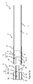
図1aは、喫煙物ロッド部分2(「エアロゾル発生部分」とも称する)と、喫煙物ロッド部分2から分離し使用者により喫煙物ロッド部分2に取付可能であるマウスピース(本例ではフィルタユニット3)とを含む喫煙物1の側面断面図である。図1bは、図1aに示される喫煙物1の斜視図である。本例では、喫煙物ロッド部分2は、レギュラー・キングサイズ型式、すなわち75mm〜91mmの範囲の長さと23mm〜25mmの範囲の外周とを有する。特に、本例では、喫煙物ロッド部分2の長さは83mmであり、24.6mmの外周を有する。喫煙物1は紙巻きたばこであり、喫煙物ロッド部分2は、被覆材料(この場合はシガレットペーパ)5にて被覆されたたばこロッド4を含む。喫煙物ロッド部分2は、その口元側の端部にフィルタ6を含み、フィルタ6は、そのたばこロッド側の端部に位置する第1のセクション7を備えている。フィルタの第1のセクション7は、本例では、第1のプラグ巻取紙(plug wrap)9にて被覆された酢酸セルロース製のトウ8から形成されている。また、フィルタ6は第1のセクション7の下流に配置された第2のセクション10を含み、この第2のセクション10は、第2のプラグ巻取紙12にて被覆された管状要素11を備える。管状要素11は、本例では、喫煙物ロッド部分2の口元側の端部で開いており、その端部に凹部ないしはキャビティ13が形成されている。管状要素11の口元側の端面16は喫煙物ロッド部分2の口元側の端部にて露出している。たばこロッド4と、フィルタの第1及び第2のセクション7,10とは、フィルタの第1及び第2のセクション7,10をオーバーラッピングし被覆材料5を部分的にオーバーラッピングするチップ材料(tipping material)14により接続されている。他の実施形態では、チップ材料14を用いてフィルタ6をたばこロッド4に接続する前に、第1及び第2のフィルタセクション7,10と、フィルタ6を形成する他のセクションを、別のプラグ巻取紙(図示せず)を用いて互いに接続することができる。
FIG. 1a shows a smoking article rod portion 2 (also referred to as an “aerosol generating portion”) and a mouthpiece (in this example, a filter unit 3) that can be separated from the smoking
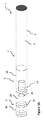
フィルタユニット3は、円柱状要素20と環状要素21とを含む。円柱状要素20は、互いに隣り合う第1の部分20a及び第2の部分20bを有し、第1及び第2の部分20a,20bはそれぞれ円柱状要素20の長さに沿って部分的に延びている。本例では、第1の部分20aは、円柱状要素20の挿入側の端部から、円柱状要素20の長さに沿う中間位置22まで延びている。本例では、円柱状要素20の長さは13mmであり、中間位置22は、円柱状要素20の長さに沿って挿入側端部から6mmである。円柱状要素20の第1の部分20aは、使用者によって喫煙物ロッド部分2の口元側端部の凹部13に挿入されるように構成されている。
The
環状要素21は、円柱状要素20の第2の部分20bの周囲に配置される。環状要素21は、凹部13の内径よりも大きな外径を有する。本例では、円柱状要素20の第2の部分20bは、円柱状要素20の口元側端部から延び、円柱状要素20の長さに沿う中間位置22で終端している。使用時に喫煙物ロッド部分2に面するよう配置された環状要素21の端部上にて、環状要素21の面23は露出するが、この面23は、後述するように、フィルタユニット3が喫煙物ロッド部分2に取り付けられたときに管状要素11の口元側の端面16に当接する。
The
円柱状要素20の第1の部分20aは、喫煙物の凹部、本例では管状要素11によって形成された凹部13に挿入されるように構成されている。凹部13の内径及び/又は長さと、円柱状要素20の第1の部分20aの外径及び/又は長さとは、円柱状要素20の第1の部分20aが凹部13内に受け入れられ該凹部13を実質的に占有することができるよう、実質的に一致するように構成されている。例えば、凹部13の内径及び/又は長さは、円柱状要素20の第1の部分20aの外径及び/又は長さと実質的に同じとすることができる。実際には、凹部13の寸法と円柱状要素20の第1の部分20aの寸法との間の一致性は、これらの構成要素を形成するために使用される材料及びそれらの間の嵌合いの所望の緊密性に依存する。円柱状要素20の凹部13への挿入を容易にするために、凹部の寸法は第1の部分20aの寸法よりも僅かに大きいことが好ましいと考えられる。
The
図1a及び図1bの例では、凹部13は5.10mmの内径を有し、円柱状要素20は5.03mmの外径を有する。別の例では、凹部13の内径及び円柱状要素20の外径は、他の値、例えば3mm〜10mmの範囲の直径を有することができる。図1a及び図1bの例では、凹部13は6mmの内部長さを有し、円柱状要素20の第1の部分20aは6mmの長さを有する。別の例では、凹部13の内部長さ及び円柱状要素20の第1の部分20aの長さは、他の値、例えば3mm〜20mmの範囲の長さを有することができる。
In the example of FIGS. 1a and 1b, the
本例では、環状要素21は、接着剤(図示せず)を用いて円柱状要素20に取り付けられている。環状要素21は、接着剤以外の手段によって、例えば摩擦嵌め又は他の固定手段などの機械的手段によって円柱状要素20に取り付けられてもよい。
In this example, the
使用時、喫煙物1は、フィルタユニット3及び喫煙物ロッド部分2を別個の構成要素として使用者に提供される。使用者が最初に喫煙物ロッド部分2を使用する前に、フィルタユニット3が、円柱状要素20の第1の部分20aを凹部13に挿入することによって喫煙物ロッド部分2に取り付けられる。円柱状要素20の第1の部分20aは、凹部13の開口部に挿入され、環状要素21の面23が管状要素11の口元側の端面16に当接して更なる挿入が防止されるまで、凹部13内に押し込まれる。使用者は、喫煙物1を喫煙する前にフィルタユニット3を喫煙物ロッド部分2に取り付けるか否かを選択することができ、このようにして喫煙物1のフィルタの長さ、ひいては喫煙物1によって生成されるエアロゾルの濾過の程度を制御することができる。
In use, the
図2aは、喫煙物ロッド部分2に取り付けられたフィルタユニット3を備えた図1a及び図1bの喫煙物1の側面断面図である。図2bは、喫煙物ロッド部分2に取り付けられたフィルタユニット3を有する同じ喫煙物1の斜視図である。
FIG. 2a is a side sectional view of the
本例では、円柱状要素20は、繊維状フィルタ材料25を含み、巻紙(この場合、プラグ巻取紙)26内にて全周が被覆され、その長手方向端部は被覆されていないままとされている。代替的実施形態では、円柱状要素20は他の方法で形成されてもよい。あるいは、円柱状要素20は他の繊維材料から形成されてもよく、異なる構造を有するように構成されてもよい。円柱状要素20は、例えば、剛性の紙、プラスチック、カード、又は他の材料から開放端または閉鎖端の中空管として形成されてもよい。円柱状要素20はまた、巻紙で被覆される必要はないが、例えば、酢酸セルロース繊維から形成された非被覆型アセテート(NWA)プラグのように、巻紙なしで形成することもできる。繊維状フィルタ材料25は、酢酸アセルロース繊維、及び/又は、ポリビニルアルコール(PVOH)、ポリ乳酸(PLA)、ポリカプロラクトン(PCL)、ポリ(1−4ブタンジオールスクシネート)(PBS)、ポリ(ブチレンアジペート−co−テレフタレート)(PBAT)、デンプンベースの材料、紙、綿、脂肪族ポリエステル材料及び多糖ポリマーのような、繊維を形成するために用いられる他の材料を含むことができる。
In the present example, the
本例では、環状要素21は、管状に形成された繊維状フィルタ材料27を含み、巻紙(この場合はプラグ巻取紙)28内に全周が被覆され、その長手方向端部は被覆されていないままとされている。代替的実施形態では、環状要素21は他の方法で形成されてもよい。例えば、環状要素21は、他の繊維材料から形成されてもよい。また、環状要素21は、巻紙で被覆される必要はないが、例えば、酢酸セルロース繊維から形成された非被覆型アセテート(NWA)チューブのような巻紙なしで形成することができる。繊維状フィルタ材料27は、酢酸アセルロース繊維、及び/又は、ポリビニルアルコール(PVOH)、ポリ乳酸(PLA)、ポリカプロラクトン(PCL)、ポリ(i−4ブタンジオールスクシネート)(PBS)、ポリ(ブチレンアジペート−co−テレフタレート)(PBAT)、デンプンベースの材料、紙、綿、脂肪族ポリエステル材料及び多糖ポリマーのような、繊維を形成するために用いられる他の材料を含むことができる。あるいはまた、環状要素21は、円柱状要素20の周りに被覆されたチップペーパのようなシート材から形成して、円柱状要素20の周りにシート材の単一又は複数の層を形成するようにしてもよい。あるいは、環状要素21は、プラスチック又は他の成形材料から形成されてもよい。
In the present example, the
円柱状要素20及び/又は環状要素21は、フィルタ可塑剤を含めてもよい。フィルタ可塑剤は繊維状フィルタ材料を軟化させることによって作用し、この繊維状フィルタ材料から、フィルタ要素は、個々の繊維が互いに接着してより剛性の高い構造を形成することができるように構成されている。トリアセチンとも呼ばれるグリセリントリアセテートのようなフィルタ可塑剤は、例えば、円柱状要素20及び/又は環状要素21がセルロースアセテートのような繊維状フィルタ材料から形成されている場合、円柱状要素20及び/又は環状要素21において使用され得る。フィルタ要素に通常使用されるレベルよりも高いレベルの可塑剤が、いずれの構成要素にも剛性を追加するために使用され得る。例えば、いずれの構成要素にも、使用される繊維状フィルタ材料の重量にして7%超え、10%超え、12%超え又は15%超えの可塑剤を使用することができる。
The
本例では、円柱状要素20における第1の部分20aの長さは、凹部13の長さに実質的に等しい。別の例では、円柱状要素20における第1の部分20aの長さは、凹部13の長さよりも短くても長くてもよい。
In this example, the length of the
円柱状要素20及び/又は環状要素21は、エアロゾル改質添加物を含むことができる。
The
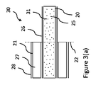
図3の(a)〜(d)は、本実施形態のフィルタユニット30,40,50,60における各マウスピースの側面断面図であり、これらのマウスピースは図1a、図1b、図2a及び図2bを参照して説明したフィルタユニット3に対するマウスピースの代替品として使用され得る。図3の(a)〜(d)のフィルタユニット30,40,50,60は、図1aのフィルタユニット3と概ね同様の構成であり、同じ参照番号は同等の特徴部を示すために使用されている。
3A to 3D are side cross-sectional views of the mouthpieces in the
図3の(a)のフィルタユニット30において、円柱状要素の繊維状フィルタ材料25は、その中にエアロゾル改質添加物31の粒子が包含されている。エアロゾル改質添加物31は、本例では、活性炭である。しかしながら、炭素以外の吸着剤や香味付与添加物のような他の添加物を使用することもできる。例えば、添加物は植物性添加物であってもよい。植物性添加物は、各自治体の許可があれば、甘草、アジサイ、朴の木の葉(Japanese white bark magnolia leaf)、カモミール、コロハ(fenigreak)、クローブ、ミント、アニス、シナモン、ハーブ、ウィンターグリーン、スペアミント、ペパーミント、ラベンダー、カルダモン、セロリ、カスカリヤ、ゼラニウム、バニラ、カッシア、キャラウェイ、ジャスミン、イランイランノキ、セージ、フェンネル、ショウガ、アニス及びコリアンダーのうちから選択された植物由来の材料を含んでもよい。
In the
本実施形態では、エアロゾル改質添加物31は、円柱状要素20の繊維質フィルタ材料25の全体にわたって分布している。エアロゾル改質添加物31は、これに代えて又は追加的に、環状要素21の繊維状フィルタ材料27の全体にわたって分布させてもよい。
In this embodiment, the
図3の(b)のフィルタユニット40では、円柱状要素20の繊維状フィルタ材料25の中に、メントールなどの香料を含む液体ペイロードを包含した易壊性カプセルが配置されている。易壊性カプセル41は、円柱状要素の第1の部分20aと第2の部分20bとの間の中間位置22に配置され、したがって、その位置で環状要素21の端部の真下に位置する。使用者は環状要素21の端部を握ってカプセルに圧力を加え、それが破れてそこに含まれる香料を放出し、フィルタユニット40を通って吸引されるエアロゾルを改質することができるようになっている。
In the
図3の(c)のフィルタユニット50では、円柱状要素20の繊維状フィルタ材料25の中に、細長いエアロゾル改質要素51が配置されている。本例では、細長いエアロゾル改質要素51は、メントールのような香料が添加された糸を含む。糸51上に添加された香料は、エアロゾルがフィルタユニット50を通って吸われるときに放出される。
In the
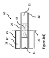
図3の(d)のフィルタユニット60において、円柱状要素20は、プラグラップ26に巻かれた長手方向に整列され互いに分離された第1のプラグ61と第2のプラグ62とを備え、これらのプラグ61,62間にキャビティが形成されるようになっている。キャビティには、図3の(a)を参照して説明したようなエアロゾル改質添加物63が配置されている。
In the
本明細書に記載にされたマウスピース又はフィルタユニットのいずれにおいても、追加のエンドフィルタセクションを設けることができる。活性炭又は植物性添加物のような添加物を含むフィルタユニットでは、追加の口元側フィルタセクションは、そのような添加物の粒子が使用者の口に達するのを防ぐことができる。 Additional end filter sections may be provided in any of the mouthpieces or filter units described herein. In filter units containing additives such as activated carbon or vegetable additives, an additional mouthside filter section may prevent particles of such additives from reaching the user's mouth.
本明細書に記載されたフィルタユニットの特徴に加えて、又はその代わりに、本明細書に記載のフィルタユニットの円柱状要素20及び/又は環状要素21を被覆する巻紙は、メントール又はチリフレーバーのような添加物を含み、付加的な風味、芳香及び/又は他の感覚的な特性をフィルタユニットに提供する。
In addition to, or instead of, the features of the filter units described herein, the wrapping paper covering the
図4は、喫煙物ロッド部分2と、この部分2とは別個のマウスピース(本例ではフィルタユニット71)とを含む喫煙物70の斜視図であり、フィルタユニット71は、このフィルタユニット71を喫煙物ロッド部分2に係合状態で保持するための少なくとも1つの隆起領域73を有する。図4の喫煙物70は、図1aの喫煙物1と構造が概ね類似しており、同じ参照番号は同等の特徴部を示すために使用されている。フィルタユニット71は、先に説明したものに対応する円柱状要素20及び環状要素21を含む。しかしながら、円柱状要素20の第1の部分20aの外面は、凹部13の内面と係合するように配置された少なくとも1つの隆起領域73を有する。本例では、このような隆起領域73が4つ、円柱状要素20の第1の部分20aの周りに周方向に配置されている。各隆起領域73は、外側表面からその最も高い点ないしは領域にてほぼ1mm突出しているが、それより高く突出していてもよく、又はそれよりも低く突出していてもよい。
FIG. 4 is a perspective view of a
本例では、隆起領域73は、平面図及び縦断面図の両方において略三角形であるが、他の形状を使用することもできる。隆起領域73は、円柱状要素の第1の部分20aの長さに沿ってそのほぼ中間に設けられ、この場合、環状要素21から約3mmの領域にある。しかし、隆起領域73は、円柱状要素20の第1の部分20aの周囲の他の位置に設けられてもよい。
In this example, the raised
隆起領域73は、凹部13内での円柱状要素20の第1の部分20aの移動を阻止するように配置されている。また、隆起領域73は、凹部内の第1の部分20aをセンタリングする効果と、円柱状要素と凹部との間に緩衝作用を与えて、いずれの構成要素の製造における公差によって生じる構成要素の寸法における不正確さを吸収するという効果とを有することができる。隆起領域73は、凹部13から外に出るよりも、凹部13内への円柱状要素20の第1の部分20aの移動に対してより小さな抵抗を与えるように構成されている。これは、本例では、円柱状要素20の外面から隆起領域73の最も高い点又は領域まで上昇するにつれて比較的急峻な傾斜を有する第1のセクション73aと、円柱状要素20の外面から隆起領域73の最高点又は領域まで上昇するにつれて比較的緩やかな傾斜を有する第2のセクション73bとを含む隆起領域73によって達成される。第2のセクション73bは、円柱状要素20の凹部13内への移動方向に向くように配置されている。第2のセクション73bは、円柱状要素20が凹部13に挿入されるときに第1のセクション73aの前方に配置される。特に、第2のセクション73bは、第1のセクション70aよりも、環状要素21とは反対側の第1の部分20aの端部に近い位置にある。したがって、隆起領域73は、第1の部分20aを凹部13に挿入する際、凹部13の内面との摩擦係合が比較的低いレベルになる。第1のセクション73aは、凹部13から円柱状要素20の外への移動方向に向くように配置されている。特に、第1のセクション73aは、環状要素21に隣接する第1の部分20aの端部により近い位置にある。したがって、隆起領域73は、凹部13から第1の部分20aを引き出す際、凹部13の内面との摩擦係合が比較的高いレベルになる。
The raised
本例では、隆起領域73は、第2のセクション73bと比較して、第1のセクション73aにおいて周方向の広がりはより大きく、これによっても円柱状要素20を挿入する場合と比較して、円柱状要素20の引出し時に凹部13の内面との摩擦係合を大きくする。本例では、第1のセクション73aにおける隆起領域73の周方向の広がりは約3mmであり、第2のセクション73bについては約0.5mmであるが、他の寸法を採用することもできる。
In this example, the raised
本例では、少なくとも1つの隆起領域73は、円柱状要素20の外面を形成する巻紙72をエンボス加工することによって形成されている。しかし、別の構成とすることもできる。例えば、隆起領域73は、ワニス、ラッカー、接着剤若しくはそれらの同等物等の付加材料、又は円柱状要素20の外面に接着されたプラスチック、紙若しくは他の材料突起によって形成することができる。さらに、円柱状要素20を挿入する場合と比較して、円柱状要素20の引出し時に凹部13の内面とより大きな摩擦係合を提供する隆起領域73の形状ならばどのようなものでも使用することができる。
In this example, the at least one raised
図5は、喫煙物ロッド部分2と、喫煙物ロッド部分2とは別個のマウスピース(本例ではフィルタユニット81)とを含む喫煙物80の斜視図である。フィルタユニット81は、少なくとも1つの周方向に延びる隆起領域83を含む。図5の喫煙物80は、図1aの喫煙物1と概ね構造が類似しており、同じ参照番号は同等の特徴部を示すために使用されている。フィルタユニット81は、先に説明したものに対応する円柱状要素20及び環状要素21を含む。しかしながら、円柱状要素20の第1の部分20aの外面は、凹部13の内面と係合するように構成された少なくとも1本の周方向に延びる隆起領域83を有する。本例では、周方向に延びる第1及び第2の隆起領域83a,83bが長手方向に離間して設けられている。しかしながら、別の実施形態では、周方向に延びる単一の隆起領域83を設けることができ、あるいは3本以上を設けることもできる。
FIG. 5 is a perspective view of a
第1及び第2の周方向に延びる隆起領域83a,83bは、それぞれ、円柱状要素20の第1の部分20aの外面の周りに連続的に延びている。特に、周方向に延びる隆起領域83a,83bは、円柱状要素20の実質的に全周にわたって延びており、本例では、円柱状要素20の周りにバンド又はリングを形成している。しかし、円柱状要素20の外面の全周ではなくその一部分に延びる周方向に延びる隆起領域、又は螺旋構成のような他のパターンを有する領域など、他の構成とすることも可能である。
The first and second circumferentially extending raised
第1及び第2の周方向に延びる隆起領域83a,83bは、それぞれ、凹部13の内面と円柱状要素20の外面との間の空気流を防止又は制限する。これは、周方向に延びる隆起領域83a,83bが、凹部13の内面に押し付けられることによって、円柱状要素の外面と凹部13の内面との間にシールを形成することで達成される。凹部13の内面と円柱状要素20の外面との間の空気流を防止又は制限することは、喫煙物ロッド部分2のフィルタ6とフィルタユニット83との間を通しての喫煙物80への外気の侵入を防止又は制限するのを助長することを可能とする。さらに、凹部13の内面と円柱状要素20の外面との間の空気流を防止又は制限することは、円柱状要素20と環状要素21との間を通ることによって円柱状要素20及び/又は環状要素21をバイパスする、喫煙物ロッド部分2によって形成されるエアロゾルを防止又は制限するのを助長することを可能とする。
The first and second circumferentially extending raised
周方向に延びる隆起領域83a,83bは、円柱状要素20の外面を形成する巻紙82をエンボス加工することによって形成することができる。本例では、周方向に延びる隆起領域83a,83bは、円柱状要素20の表面より1mmの高さとなっており、幅は1mmである。しかし、幅が0.5mm〜10mm、高さが0.5mm〜5mmの間のような他の寸法を使用することができる。また、本例では、第1及び第2の周方向に延びる隆起領域83a,83bは、2mmの間隔をもって分離されているが、円柱状要素20のサイズ及び構成に応じて、1mm〜20mmのような他の間隔とすることもできる。周方向に延びる隆起領域83は、円柱状要素の第1の部分20aの長さに沿ってほぼ中間に設けられ、この場合、環状要素21から約3mmの領域にある。しかしながら、円柱状要素20の第1の部分20aの周囲の他の位置に、周方向に延びる隆起部分83を代替的に設けることができる。
The raised
図6は、喫煙物ロッド部分2と、喫煙物ロッド部分2とは別個のマウスピース(本例ではフィルタユニット91)とを含む喫煙物90の斜視図であり、フィルタユニット91は、図4を参照して説明した少なくとも1つの隆起領域73と、図5を参照して説明した少なくとも1つの周方向に延びる隆起領域83とを含む。図6の喫煙物90は、図1aの喫煙物1と構造が概ね類似しており、同じ参照番号は、同等の特徴部を示すために使用されている。少なくとも1つの隆起領域73は、少なくとも1つの周方向に延びる隆起領域83よりも環状要素21から離れた円柱状要素20の第1の部分20aの外面に設けられている。本例では、4つの隆起領域73が、円柱状要素20の周囲に間隔をあけて設けられ、環状要素21から約4mm離間して設けられている。第1及び第2の周方向に延びる隆起領域83が、環状要素21から約2mm離間して設けられている。隆起領域73及び周方向に延びる隆起領域83は、円柱状要素20の外面を形成する巻紙92をエンボス加工することによって形成することができる。
FIG. 6 is a perspective view of a
図7は、喫煙物ロッド部分2と、喫煙物ロッド部分2とは別個のマウスピース(本例ではフィルタユニット101)とを含む喫煙物100の斜視図であり、フィルタユニット101は、喫煙物ロッド部分2と係合状態でフィルタユニット101を保持するための少なくとも1つの周方向に延びる隆起領域103を備えている。図7の喫煙物100は、図1aの喫煙物1と概ね構造が類似しており、同じ参照番号が同等の特徴部を示すために使用されている。少なくとも1つの周方向に延びる隆起領域103は、図4を参照して説明した少なくとも1つの隆起領域73と、図5を参照して説明した少なくとも1つの周方向に延びる隆起領域との組み合わせた機能を有している。特に、周方向に延びる隆起領域103は、円柱状要素20の外面から隆起領域103の最も高い点又は領域まで上昇するにつれて比較的な緩やかな傾斜を有する前方セクション103bと、円柱状要素20の外面から隆起領域103の最高点又は領域まで上昇するにつれて比較的急峻な傾斜を有する後方セクション103aとを含むように形成されている。したがって、周方向に延びる隆起領域103は、凹部13への円柱状要素20の挿入時に凹部13の内面との摩擦係合のレベルを比較的低くし、凹部13からの円柱状要素20の引出し時には凹部13の内面との摩擦係合のレベルを比較的高くする。さらに、周方向に延びる隆起領域103は、凹部13の内面と円柱状要素20の外面との間の空気の流れを防止又は制限するようにも機能する。
FIG. 7 is a perspective view of a
図8は、本明細書に記載された喫煙物とともに使用するための、オフセット型の円柱状要素20を有するマウスピース(本例ではフィルタユニット110)の側面断面図である。フィルタユニット110は、円柱状要素20と、環状要素111とを含む。円柱状要素20は、先に説明した円柱状要素20と実質的に同じである。しかし、本例では、環状要素111は、円柱状要素20の第2の部分20bの周囲に配置され、円柱状要素20の口元側の端部を越えて延びている。本例では、環状要素111は、円柱状要素20と同じ長手方向長さを有する。特に、本例では、円柱状要素20と環状要素21の両方が13mmの長さを有する。中間位置22は、先に説明したように、挿入側の端部から円柱状要素20の長さに沿って6mmであり、したがって、環状要素21は円柱状要素20の口元側端部を超えて6mm延びている。環状要素111は、チップペーパなどの巻紙112内に被覆される。したがって、図8のフィルタユニット110は、その口元側端部に、本明細書で説明するフィルタユニットの円柱状要素20の第1の部分20aを受け入れることができる凹部113を有する。
FIG. 8 is a side cross-sectional view of a mouthpiece (filter
図8のフィルタユニット110は、図3の(a)〜(d)のフィルタユニットのいずれかの特徴を含むように構成することができる。したがって、使用者は、図8に示すものであるが、エアロゾル改質添加物を含む第1のフィルタユニット110を選択し、それを本明細書で説明するような喫煙物ロッド部分2に取り付けることができる。次いで、使用者は、本明細書に記載のフィルタユニットのいずれかから選択された別の第2のフィルタユニットを選択し、そのフィルタユニットを第1のフィルタユニット110に取り付けることができる。これにより、使用者は、同じ喫煙物ロッド部分2に接続することができる複数のフィルタユニットの複数の特性、例えばろ過特性やエアロゾル改質特性などの特性を得ることができる。
The
図9は、喫煙物ロッド部分2と、喫煙物ロッド部分2に接続された図8のフィルタユニット110の第1のもの110a及び第2のもの110bとを含む喫煙物120の側面断面図である。図9の喫煙物120は、図1aの喫煙物1と概ね構造が類似しており、同じ参照番号が同等の特徴部を示すために使用されている。
FIG. 9 is a side cross-sectional view of a
図10は、本明細書に記載のマウスピース(本例ではフィルタユニット)を形成するための方法を示す流れ図である。第1のステップ(S101)において、互いに隣り合う第1の部分と第2の部分とを有する、フィルタ材料からなる細長い円柱体が形成される。第1の部分は喫煙物の対応する凹部に挿入されるように構成される。円柱体は、例えばフィルタロッドメーカを使用して形成することができる。フィルタロッドメーカにおいては、フィルタトウ(filter tow)がその供給源からフィルタロッドメーカの装飾セクション内に供給され、そこでフィルタトウは棒状に圧縮され、プラグ巻取紙のような巻紙に被覆される。プラグ巻取紙には、隆起領域73を形成するエンボス加工された隆起領域と、本明細書で述べた周方向に延びる隆起領域83とを設けることができる。円柱体は、フィルタロッドメーカにて最終長さに切断することができ、又は所望の最終長さの倍数である長さに切断することができ、その後、環状要素21と組み合わされたときに適当なサイズに切断することができる。第2ステップ(S102)において、環状要素21が、ステップS101で形成された細長い円柱状の第2の部分20bの周りに付けられる。例えば、環状要素21は、円柱体の周りにシート材料を巻き付けることにより、又は筒状フィルタセクションを円柱の上に滑らせることによって形成することができる。いずれの場合においても、環状要素21は、接着剤を用いて円柱状要素の外面に接着することができる。
FIG. 10 is a flow chart illustrating a method for forming a mouthpiece (in this example, a filter unit) described herein. In the first step (S101), an elongated cylindrical body made of a filter material having a first portion and a second portion adjacent to each other is formed. The first portion is configured to be inserted into the corresponding recess of the smoking article. The cylinder can be formed using, for example, a filter rod maker. In a filter rod maker, a filter tow is fed from its source into the decorative section of the filter rod maker, where the filter tow is compressed into bars and coated on a paper wrapper such as a plug web. The plug web can be provided with embossed raised areas forming raised
図11は、図4を参照して本明細書で説明したフィルタユニット71の円柱状要素を形成する方法を示す流れ図である。第1のステップ(S201)において、少なくとも1つの隆起領域が設けられた被覆材料が形成される。例えば、プラグラップのようなシート状被覆材料には、エンボス加工又は他の方法で、少なくとも1つの隆起領域が設けられ得る。第2のステップ(S202)において、例えばフィルタロッドメーカを使用してフィルタ材料からなる細長い円柱体が形成される。円柱体は、例えば、フィルタロッドメーカを使用して形成することができ、フィルタロッドメーカにおいて、フィルタトウがその供給源からフィルタロッドメーカの装飾セクションに供給され、そこで棒状に圧縮される。第3のステップ(S203)において、被覆材料は、フィルタ材料からなる細長い円柱体の周りに被覆される。フィルタ材料からなる円柱体は、フィルタロッドメーカにて最終長さに切断することができ、又は所望の最終長さの倍数である長さに切断することができ、その場合、後の段階で適当なサイズに切断することができる。
11 is a flow chart illustrating a method of forming the cylindrical elements of the
図12は、図5を参照して本明細書で説明したフィルタユニット81の円柱状要素を形成する方法を示す流れ図である。第1のステップ(S301)において、少なくとも1つの周方向に延びる隆起領域が設けられた被覆材料が形成される。例えば、プラグ巻取紙のようなシート状の被覆材料には、少なくとも1つの周方向に延びる隆起領域がエンボス加工又は他の方法で設けられ得る。第2のステップ(S302)において、例えばフィルタロッドメーカを使用してフィルタ材料からなる細長い円柱体が形成される。円柱体は、例えばフィルタロッドメーカを使用して形成することができ、フィルタロッドメーカにおいて、フィルタトウがその供給源からフィルタロッドメーカの装飾セクションに供給され、そこで棒状に圧縮される。第3のステップ(S303)において、被覆材料は、フィルタ材料からなる細長い円柱体の周囲に被覆される。フィルタ材料の円柱体は、フィルタロッドメーカにて最終長さに切断することができ、又は所望の最終長さの倍数である長さに切断することができ、その場合、後の段階で適当なサイズに切断することができる。
12 is a flow chart illustrating a method of forming the cylindrical elements of the
本明細書に記載の喫煙物は、喫煙物の使用前又は使用中に、喫煙物の特性を変更する可能性を使用者に提供する。本明細書に記載のフィルタユニット3,30,40,50,60,71,81,91,101,110のいずれかを喫煙物ロッド部分2のいずれかに取り付けることができる。例えば、使用者には、1つ以上の喫煙物ロッド部分2と、使用者によってロッド部分2に選択的に取り付けることができるフィルタユニット3,30,40,50,60,71,81,91,101,110から選んだ一つとが提供され得る。
The smoking article described herein offers the user the possibility to alter the properties of the smoking article before or during use of the smoking article. Any of the
フィルタユニット3,30,40,50,60,71,81,91,101,110と、喫煙物ロッド部分2とのための特定の構成を本明細書に記載したが、代替的な設計構造もあり得る。例えば、いくつかの実施形態では、各フィルタユニット3,30,40,50,60,71,81,91,101,110の環状要素21を省略することができ、円柱状要素20のみを備えるフィルタユニットを提供することができる。この場合、円柱状要素20は、第1の部分20a及び第2の部分20bの両方を備えてもよく、凹部13内に受容されるように構成された第1の部分20aのみを備えてもよい。本明細書に記載のフィルタユニット以外のマウスピース、例えばプラスチック(ポリ塩化ビニル又は他の同様のポリマー材料)、紙又はカードのような材料から形成された、軸線方向の流路が貫設された管状マウスピースなどを使用することができる。濾過機能を果たさないマウスピース、又は限定された濾過機能しかないマウスピースは、熱不燃焼(HnB)製品のような不燃性喫煙物、及び電子たばこなどのエアロゾル発生装置のような他のニコチン送達製品で使用するために提供されてもよい。そのようなマウスピースは、例えば、本明細書に記載のフィルタユニットと同じ構造及び材料を含むことができる。さらに、喫煙物ロッド部分2は第1及び第2のフィルタセクション7,10を有するものとして説明したが、第1のフィルタセクション7のみを含んでもよいし、第1及び第2のフィルタセクション7,10に加えて追加のフィルタセクションを含んでもよい。例えば、本明細書に記載の喫煙物ロッド部分2は、フィルタ6のたばこロッド端部に追加の第3のフィルタセクション(内部に活性炭などの吸着剤が分散されたもの)を含めてもよい。さらに、喫煙物ロッド部分2は、第2のフィルタセクション10を含む必要はなく、代わりに、剛性のあるプラグラップ又はチップ材料により形成された喫煙物ロッド部分2の口元側端部に凹部13を有するものとすることができる。この場合、対応するフィルタユニットは、この別の凹部構成に適合するように構成される。
Although specific configurations have been described herein for the
隆起領域73,83,103を対応の巻紙に形成するためにエンボス加工をすることが本明細書に記載されている。そのような巻紙は、適切な形状とされた一対の互いに協働するローラ間にてエンボス加工されて、隆起領域73,83,103を形成することができる。複数の巻紙がローラ間で同時に並列的にエンボス加工されてもよい。
Embossing is described herein to form raised
様々な問題に対処し、当該技術を進歩させるために、本開示の全体は、特許請求された発明が具現化され且つ優れた喫煙物及びフィルタユニットを提供する様々な例を実例として示すものである。本開示の利点及び特徴は、例示のためだけの代表的な例にすぎず、網羅的及び/又は排他的なものではない。本開示は、特許請求した特徴を理解し、教示するためにのみ提示されるものである。本開示の利点、例、機能、特徴、構造及び/又は他の態様は、特許請求の範囲によって規定される開示内容についての限定、又は特許請求の範囲と同等の制限についての限定とみなされるべきではなく、本開示の範囲及び/又は精神から逸脱することなく、他の例を利用して改変がなされ得る。様々な例は、開示された要素、構成部品、特徴、部品、工程、手段などの様々な組み合わせを適切に含み、それらから構成され、又は本質的に構成され得るものである。 To address various problems and improve the art, the entire disclosure presents various examples in which the claimed invention may be embodied and provide superior smoking articles and filter units. is there. The advantages and features of this disclosure are merely representative examples for purposes of illustration only, and are not exhaustive and / or exclusive. This disclosure is presented only to understand and teach the claimed features. Advantages, examples, functions, features, structures and / or other aspects of the present disclosure should be considered as limitations on the disclosure defined by the claims or limitations equivalent to the claims. Rather, modifications may be made utilizing other examples without departing from the scope and / or spirit of the disclosure. Various examples may suitably include, consist of, or consist essentially of various combinations of the disclosed elements, components, features, parts, processes, means, etc.
Claims (15)
前記円柱状要素が、少なくとも1つの隆起領域を有する外面を備え、前記少なくとも1つの隆起領域が、前記凹部内での前記円柱状要素の移動に対して抵抗を与えるべく前記凹部の内面と係合するように構成されており、前記少なくとも1つの隆起領域が、前記凹部から外への前記円柱状要素の移動よりも、前記凹部内への前記円柱状要素の移動に対してより小さな抵抗を与えるように構成されている、マウスピース。 A mouthpiece attachable to a smoking rod portion, the mouthpiece comprising an elongated cylindrical element formed of plastic as a hollow tube configured to be inserted into a recess by a user,
The cylindrical element includes an outer surface having at least one raised region, the at least one raised region engaging an inner surface of the recess to provide resistance to movement of the cylindrical element within the recess. And the at least one raised region provides less resistance to movement of the cylindrical element into the recess than movement of the cylindrical element out of the recess. A mouthpiece that is configured to
それぞれ前記円柱状要素の長さに沿って部分的に延び、互いに隣り合う第1の部分及び第2の部分であり、前記第1の部分が使用者によって前記凹部に挿入されるように構成されている、第1の部分及び第2の部分と、
前記円柱状要素の前記第2の部分の周囲に配置され、前記凹部の内径よりも大きな外径を有する環状要素と
を備える、請求項1に記載のマウスピース。 The cylindrical element is
A first portion and a second portion, each extending partially along the length of the cylindrical element and adjacent to each other, the first portion being configured to be inserted into the recess by a user. And a first part and a second part,
The mouthpiece according to claim 1, further comprising an annular element disposed around the second portion of the cylindrical element and having an outer diameter larger than an inner diameter of the recess.
前記煙改質添加物が、少なくとも1つの易壊性カプセル内に収容されていること、
前記煙改質添加物が、植物性添加物を含むことと、
前記煙改質添加物が、吸着剤を含むことと、
前記煙改質添加物が、前記円柱状要素及び/又は前記環状要素中で延びる繊維に付着されていることと、
の全て、又は、これらの少なくとも一つである、請求項5に記載のマウスピース。 The smoke modifying additive being dispersed throughout the cylindrical and / or annular elements;
The smoke modifying additive is contained within at least one fragile capsule;
The smoke-modifying additive comprises a vegetable additive,
The smoke modifying additive includes an adsorbent,
Said smoke modifying additive being attached to fibers extending in said cylindrical element and / or said annular element;
6. The mouthpiece according to claim 5, which is all or at least one of them.
前記第2のセクションは、前記円柱状要素が前記凹部に挿入されるときに前記第1のセクションの前方に配置される、請求項1〜7のいずれか一項に記載のマウスピース。 The at least one raised region has a first section with a relatively steep slope as it rises away from the outer surface of the cylindrical element, and relatively gentle as it rises away from the outer surface of the cylindrical element. A second section with a different slope,
The mouthpiece according to any one of claims 1 to 7, wherein the second section is arranged in front of the first section when the cylindrical element is inserted into the recess.
請求項1〜14のいずれか一項に記載のマウスピースと、
を備える、喫煙物。
A smoking article rod portion having a recess,
The mouthpiece according to any one of claims 1 to 14,
A smoking article.
Priority Applications (1)
| Application Number | Priority Date | Filing Date | Title |
|---|---|---|---|
| JP2020052844A JP6958968B2 (en) | 2015-02-27 | 2020-03-24 | Smoking and smoking mouthpieces |
Applications Claiming Priority (3)
| Application Number | Priority Date | Filing Date | Title |
|---|---|---|---|
| GB1503390.5 | 2015-02-27 | ||
| GB201503390A GB201503390D0 (en) | 2015-02-27 | 2015-02-27 | A smoking article and filter unit therefor |
| PCT/GB2016/050503 WO2016135502A1 (en) | 2015-02-27 | 2016-02-26 | A smoking article and mouthpiece therefor |
Related Child Applications (1)
| Application Number | Title | Priority Date | Filing Date |
|---|---|---|---|
| JP2020052844A Division JP6958968B2 (en) | 2015-02-27 | 2020-03-24 | Smoking and smoking mouthpieces |
Publications (3)
| Publication Number | Publication Date |
|---|---|
| JP2018506288A JP2018506288A (en) | 2018-03-08 |
| JP2018506288A5 JP2018506288A5 (en) | 2019-10-17 |
| JP6683403B2 true JP6683403B2 (en) | 2020-04-22 |
Family
ID=52876277
Family Applications (2)
| Application Number | Title | Priority Date | Filing Date |
|---|---|---|---|
| JP2017543350A Active JP6683403B2 (en) | 2015-02-27 | 2016-02-26 | Smoking articles and mouthpieces for smoking articles |
| JP2020052844A Active JP6958968B2 (en) | 2015-02-27 | 2020-03-24 | Smoking and smoking mouthpieces |
Family Applications After (1)
| Application Number | Title | Priority Date | Filing Date |
|---|---|---|---|
| JP2020052844A Active JP6958968B2 (en) | 2015-02-27 | 2020-03-24 | Smoking and smoking mouthpieces |
Country Status (11)
| Country | Link |
|---|---|
| US (1) | US20180035706A1 (en) |
| EP (2) | EP3261462B1 (en) |
| JP (2) | JP6683403B2 (en) |
| KR (2) | KR102349316B1 (en) |
| CN (1) | CN107529818B (en) |
| CA (1) | CA3014886C (en) |
| GB (1) | GB201503390D0 (en) |
| HK (1) | HK1249372A1 (en) |
| PL (1) | PL3261462T3 (en) |
| RU (1) | RU2674975C1 (en) |
| WO (1) | WO2016135502A1 (en) |
Families Citing this family (3)
| Publication number | Priority date | Publication date | Assignee | Title |
|---|---|---|---|---|
| GB201503390D0 (en) * | 2015-02-27 | 2015-04-15 | British American Tobacco Co | A smoking article and filter unit therefor |
| GB201715924D0 (en) * | 2017-09-29 | 2017-11-15 | British American Tobacco Investments Ltd | A filter unit for a smoking article |
| CN113229521A (en) * | 2021-06-23 | 2021-08-10 | 张家港外星人新材料科技有限公司 | Electronic atomized liquid composition and packaging container thereof |
Family Cites Families (18)
| Publication number | Priority date | Publication date | Assignee | Title |
|---|---|---|---|---|
| US4809718A (en) * | 1987-05-06 | 1989-03-07 | R. J. Reynolds Tobacco Company | Variable air dilution cigarette filters |
| US5404890A (en) * | 1993-06-11 | 1995-04-11 | R. J. Reynolds Tobacco Company | Cigarette filter |
| DE4334153C1 (en) * | 1993-10-01 | 1994-12-15 | Ideal Standard | Connection coupling |
| JP2005245258A (en) * | 2004-03-02 | 2005-09-15 | Shetech:Kk | Filter tip containing platinum nano particles, and smoking object having the filter tip or solution of platinum nanoparticles |
| US20070000505A1 (en) * | 2005-02-24 | 2007-01-04 | Philip Morris Usa Inc. | Smoking article with tobacco beads |
| EP1754419A1 (en) * | 2005-08-15 | 2007-02-21 | Philip Morris Products S.A. | Liquid release device for a smoking article |
| US8100134B2 (en) * | 2006-02-22 | 2012-01-24 | Philip Morris Usa Inc. | Ventilated smoking article |
| GB0724408D0 (en) * | 2007-12-14 | 2008-01-30 | British American Tobacco Co | Recessed ventilation for smoking articles |
| JP5178829B2 (en) * | 2008-06-25 | 2013-04-10 | 日本たばこ産業株式会社 | Smoking article |
| US8997755B2 (en) * | 2009-11-11 | 2015-04-07 | R.J. Reynolds Tobacco Company | Filter element comprising smoke-altering material |
| US10609955B2 (en) * | 2011-04-08 | 2020-04-07 | R.J. Reynolds Tobacco Company | Filtered cigarette comprising a tubular element in filter |
| GB2490732A (en) * | 2011-05-13 | 2012-11-14 | British American Tobacco Co | Filter for a smoking article |
| GB201110863D0 (en) * | 2011-06-27 | 2011-08-10 | British American Tobacco Co | Smoking article filter and insertable filter unit thereof |
| AT512347B1 (en) * | 2011-12-23 | 2013-09-15 | Tannpapier Gmbh | AS A FILM TRAINED MOUTHPIECE OF A FILTER CIGARETTE |
| GB201217893D0 (en) * | 2012-10-05 | 2012-11-21 | British American Tobacco Co | A smoking article |
| GB201223159D0 (en) * | 2012-12-21 | 2013-02-06 | British American Tobacco Co | Insertable filter unit |
| WO2014102095A2 (en) * | 2012-12-31 | 2014-07-03 | Philip Morris Products S.A. | Smoking article including flow restrictor in hollow tube |
| GB201503390D0 (en) * | 2015-02-27 | 2015-04-15 | British American Tobacco Co | A smoking article and filter unit therefor |
-
2015
- 2015-02-27 GB GB201503390A patent/GB201503390D0/en not_active Ceased
-
2016
- 2016-02-26 PL PL16711334.9T patent/PL3261462T3/en unknown
- 2016-02-26 EP EP16711334.9A patent/EP3261462B1/en active Active
- 2016-02-26 EP EP23213831.3A patent/EP4305974A3/en active Pending
- 2016-02-26 JP JP2017543350A patent/JP6683403B2/en active Active
- 2016-02-26 KR KR1020197034010A patent/KR102349316B1/en active IP Right Grant
- 2016-02-26 CN CN201680024489.3A patent/CN107529818B/en active Active
- 2016-02-26 US US15/554,059 patent/US20180035706A1/en not_active Abandoned
- 2016-02-26 RU RU2017133470A patent/RU2674975C1/en active
- 2016-02-26 WO PCT/GB2016/050503 patent/WO2016135502A1/en active Application Filing
- 2016-02-26 KR KR1020177023988A patent/KR20170109009A/en active Application Filing
- 2016-02-26 CA CA3014886A patent/CA3014886C/en active Active
-
2018
- 2018-06-22 HK HK18108006.5A patent/HK1249372A1/en unknown
-
2020
- 2020-03-24 JP JP2020052844A patent/JP6958968B2/en active Active
Also Published As
| Publication number | Publication date |
|---|---|
| JP6958968B2 (en) | 2021-11-02 |
| EP4305974A2 (en) | 2024-01-17 |
| CN107529818A (en) | 2018-01-02 |
| CA3014886A1 (en) | 2016-09-01 |
| CA3014886C (en) | 2023-12-19 |
| PL3261462T3 (en) | 2024-03-18 |
| GB201503390D0 (en) | 2015-04-15 |
| KR102349316B1 (en) | 2022-01-07 |
| KR20170109009A (en) | 2017-09-27 |
| CN107529818B (en) | 2020-12-08 |
| EP4305974A3 (en) | 2024-04-17 |
| HK1249372A1 (en) | 2018-11-02 |
| RU2674975C1 (en) | 2018-12-13 |
| JP2020114231A (en) | 2020-07-30 |
| WO2016135502A1 (en) | 2016-09-01 |
| EP3261462B1 (en) | 2023-12-13 |
| EP3261462A1 (en) | 2018-01-03 |
| JP2018506288A (en) | 2018-03-08 |
| KR20190130690A (en) | 2019-11-22 |
| US20180035706A1 (en) | 2018-02-08 |
Similar Documents
| Publication | Publication Date | Title |
|---|---|---|
| JP6936938B2 (en) | Smoking and smoking mouthpieces | |
| JP6958968B2 (en) | Smoking and smoking mouthpieces | |
| US11425928B2 (en) | Smoking article and mouthpiece therefor | |
| RU2772186C2 (en) | Smoking product and mouthpiece for it |
Legal Events
| Date | Code | Title | Description |
|---|---|---|---|
| A621 | Written request for application examination |
Free format text: JAPANESE INTERMEDIATE CODE: A621 Effective date: 20171002 |
|
| A977 | Report on retrieval |
Free format text: JAPANESE INTERMEDIATE CODE: A971007 Effective date: 20180921 |
|
| A131 | Notification of reasons for refusal |
Free format text: JAPANESE INTERMEDIATE CODE: A131 Effective date: 20181030 |
|
| A521 | Request for written amendment filed |
Free format text: JAPANESE INTERMEDIATE CODE: A523 Effective date: 20190121 |
|
| A131 | Notification of reasons for refusal |
Free format text: JAPANESE INTERMEDIATE CODE: A131 Effective date: 20190618 |
|
| A524 | Written submission of copy of amendment under article 19 pct |
Free format text: JAPANESE INTERMEDIATE CODE: A524 Effective date: 20190905 |
|
| RD04 | Notification of resignation of power of attorney |
Free format text: JAPANESE INTERMEDIATE CODE: A7424 Effective date: 20190919 |
|
| TRDD | Decision of grant or rejection written | ||
| A01 | Written decision to grant a patent or to grant a registration (utility model) |
Free format text: JAPANESE INTERMEDIATE CODE: A01 Effective date: 20200225 |
|
| A61 | First payment of annual fees (during grant procedure) |
Free format text: JAPANESE INTERMEDIATE CODE: A61 Effective date: 20200324 |
|
| R150 | Certificate of patent or registration of utility model |
Ref document number: 6683403 Country of ref document: JP Free format text: JAPANESE INTERMEDIATE CODE: R150 |
|
| S111 | Request for change of ownership or part of ownership |
Free format text: JAPANESE INTERMEDIATE CODE: R313113 |
|
| R350 | Written notification of registration of transfer |
Free format text: JAPANESE INTERMEDIATE CODE: R350 |
|
| R250 | Receipt of annual fees |
Free format text: JAPANESE INTERMEDIATE CODE: R250 |
|
| R250 | Receipt of annual fees |
Free format text: JAPANESE INTERMEDIATE CODE: R250 |