JP6680518B2 - Vehicle transportation method - Google Patents

Vehicle transportation method Download PDF

Info

Publication number
JP6680518B2
JP6680518B2 JP2015227553A JP2015227553A JP6680518B2 JP 6680518 B2 JP6680518 B2 JP 6680518B2 JP 2015227553 A JP2015227553 A JP 2015227553A JP 2015227553 A JP2015227553 A JP 2015227553A JP 6680518 B2 JP6680518 B2 JP 6680518B2
Authority
JP
Japan
Prior art keywords
vehicle
carriage
arm
gripping
wheel
Prior art date
Legal status (The legal status is an assumption and is not a legal conclusion. Google has not performed a legal analysis and makes no representation as to the accuracy of the status listed.)
Active
Application number
JP2015227553A
Other languages
Japanese (ja)
Other versions
JP2017095926A (en
JP2017095926A5 (en
Inventor
右季 小野
右季 小野
Current Assignee (The listed assignees may be inaccurate. Google has not performed a legal analysis and makes no representation or warranty as to the accuracy of the list.)
IHI Transport Machinery Co Ltd
Original Assignee
IHI Transport Machinery Co Ltd
Priority date (The priority date is an assumption and is not a legal conclusion. Google has not performed a legal analysis and makes no representation as to the accuracy of the date listed.)
Filing date
Publication date
Application filed by IHI Transport Machinery Co Ltd filed Critical IHI Transport Machinery Co Ltd
Priority to JP2015227553A priority Critical patent/JP6680518B2/en
Publication of JP2017095926A publication Critical patent/JP2017095926A/en
Publication of JP2017095926A5 publication Critical patent/JP2017095926A5/ja
Application granted granted Critical
Publication of JP6680518B2 publication Critical patent/JP6680518B2/en
Active legal-status Critical Current
Anticipated expiration legal-status Critical

Links

Images

Landscapes

  • Vehicle Cleaning, Maintenance, Repair, Refitting, And Outriggers (AREA)
  • Automobile Manufacture Line, Endless Track Vehicle, Trailer (AREA)

Description

本発明は、駐車場や自動車整備工場等の施設において車両を搬送するための方法に関する。 The present invention relates to a method for transporting a vehicle in a facility such as a parking lot or an automobile maintenance shop.

従来、任意の位置に停車した車両を駐車施設等における所定位置に搬送できるようにした入出車装置の一般的技術水準を示すものとしては、例えば、特許文献1がある。   For example, Japanese Patent Application Laid-Open Publication No. 2004-242242 discloses a general state of the art of an entry / exit device that can transport a vehicle stopped at an arbitrary position to a predetermined position in a parking facility or the like.

特許文献1に示される装置は、それぞれ車両支持機構及び走行機構を備える左側搬送台車と右側搬送台車とからなり、該左側搬送台車と右側搬送台車とが互いに独立して移動しつつ、協働して車両を支持し、搬送するようになっている。   The device disclosed in Patent Document 1 is composed of a left-side transport vehicle and a right-side transport vehicle each having a vehicle support mechanism and a traveling mechanism, and the left-side transport vehicle and the right-side transport vehicle move independently of each other and cooperate with each other. It supports and transports the vehicle.

前記左側搬送台車と右側搬送台車は、無線通信によってリアルタイムに情報交換を行うことにより、協働する。   The left and right transport carriages cooperate by exchanging information in real time by wireless communication.

しかしながら、特許文献1に示されるような搬送台車では、車両の左右両側に充分な空きスペースがない場合、該車両の左右両側に搬送台車が寄り付くことができず、車両を搬送することができなくなるという欠点を有していた。   However, in the transport vehicle as shown in Patent Document 1, when there is not enough empty space on the left and right sides of the vehicle, the transport vehicle cannot approach the left and right sides of the vehicle, and the vehicle cannot be transported. It had a drawback.

また、車両の試験設備等においては、作業員が数人で車両を押しながら移動させることもある。このような場合、作業員の負担が大きく、手間と時間がかかってしまうため、簡単な構成で車両を確実に搬送できる装置の開発が望まれていた。   Further, in a vehicle test facility or the like, several workers may move the vehicle while pushing the vehicle. In such a case, the burden on the worker is great, and it takes time and labor, and therefore there has been a demand for the development of an apparatus capable of reliably transporting the vehicle with a simple configuration.

そこで、本発明者等は、車両の左右両側に充分な空きスペースがなくても、簡単な構成で車両を確実に搬送し得る車両の搬送装置を提案し出願している。本発明者等によるこの種の技術文献としては、例えば、下記特許文献2がある。また、立体駐車場等の設備で利用される車両の搬送装置ないし方法に関する一般的技術水準を示すものとしては、例えば、特許文献3がある。   Therefore, the inventors of the present invention have proposed and filed a vehicle transporting device that can reliably transport the vehicle with a simple configuration even if there are not enough empty spaces on the left and right sides of the vehicle. As a technical document of this kind by the present inventors, for example, there is Patent Document 2 below. Further, as a general technical level relating to a vehicle carrying device or method used in equipment such as a multi-storey parking lot, there is Patent Document 3, for example.

特許文献2には、車両の車輪を前後から挟み付けるように支持しつつリフトアップする一対のリフトバーを備えたリフターを、台車本体の前後左右に計四基備えた車両の搬送装置が記載されている。車両の搬送にあたっては、前記リフターのリフトバーのうち、車両に対して後輪の後側に位置するリフトバーのみを展開位置に回動させ、それ以外は格納位置に回動させておく。続いて前記台車本体を車両下部に進入させると、格納位置に回動したリフトバーは車輪の間を通過するが、展開位置に回動した後輪の後側に位置するリフトバーは後輪に当接し、前記台車本体を車両に対して位置決めすることになる。その後、全リフトバーを展開位置に回動させることで各車輪を前後から挟み付けるように支持しつつリフトアップするようにしている。   Patent Document 2 describes a vehicle transfer device including a lifter including a pair of lift bars that lift up while supporting the wheels of the vehicle so as to sandwich the wheels from the front and rear, and a total of four lifters on the front, rear, left, and right of the bogie body. There is. When transporting the vehicle, among the lift bars of the lifter, only the lift bar located on the rear side of the rear wheels of the vehicle is rotated to the deployed position, and the other lift bars are rotated to the retracted position. Then, when the trolley body is advanced to the lower part of the vehicle, the lift bar rotated to the storage position passes between the wheels, but the lift bar located on the rear side of the rear wheel rotated to the deployed position contacts the rear wheel. The carriage main body is positioned with respect to the vehicle. After that, by rotating all the lift bars to the deployed position, the wheels are lifted while being supported so as to sandwich each wheel from the front and rear.

特許文献3には、前後二組の台車それぞれの左右に、自動車の車輪を前後方向から一対のアーム(第一アーム及び第二アーム)で挟持するタイヤ挟持装置を備えた車両の搬送装置が記載されている。車両の搬送にあたっては、前後の台車に備えた前記アームを前後方向に開いた状態で、前記前後の台車を前後輪の間に移動させてから、前記アームを水平方向に所定の位置まで回動させて前後輪を前後から挟持するようにしている。   Patent Document 3 describes a vehicle conveyance device including a tire clamping device that clamps a wheel of a vehicle from a front-rear direction with a pair of arms (first arm and second arm) on the left and right of each of two sets of front and rear bogies. Has been done. When transporting a vehicle, move the front and rear bogies between the front and rear wheels with the arms of the front and rear bogies opened in the front and rear directions, and then rotate the arms horizontally to a predetermined position. The front and rear wheels are clamped from the front and back.

特開2004−169451号公報JP 2004-169451 A 特開2013−19210号公報JP, 2013-19210, A 特開2015−40405号公報JP, 2005-40405, A

しかしながら、特許文献2に開示されている車両の搬送装置においては、車両の前輪と後輪を持ち上げるリフターの前後方向における間隔や、前記台車本体に対する位置が一定であるため、搬送可能となる車両のホイールベースや前後のオーバーハングが限定されていた。   However, in the vehicle transporting device disclosed in Patent Document 2, since the distance between the lifters for lifting the front wheels and the rear wheels of the vehicle in the front-rear direction and the position with respect to the bogie body are constant, the vehicle can be transported. The wheelbase and front and rear overhangs were limited.

特許文献3に開示されている車両の搬送装置では、第一アームと第二アームとが同時に動作するので、車両の搬送の際、台車ないしタイヤ挟持装置の位置を車両に対して正確に合わせてから前記第一アームと第二アームを作動させる必要があり、車両に対する搬送装置の位置決めが難しい。また、前後の台車同士の距離が一定であるため、搬送可能となる車両のホイールベースが限定されるという上記特許文献2と同様の問題もあった。   In the vehicle transfer device disclosed in Patent Document 3, since the first arm and the second arm operate simultaneously, when the vehicle is transferred, the position of the trolley or the tire pinching device is accurately aligned with the vehicle. Therefore, it is necessary to operate the first arm and the second arm, which makes it difficult to position the transport device with respect to the vehicle. Further, since the distance between the front and rear bogies is constant, there is a problem similar to that of Patent Document 2 in that the wheel base of the vehicle that can be transported is limited.

しかも、これらの車両の搬送装置では、リフトバーやアームを車輪の前後で回動させるので、車両の搬送の際、車輪の周辺にリフトバーやアームの回動を妨げるような物体がないことが必要である。したがって、車輪止め等が設置された場所では使用することができず、搬送に先立って装置に対し車両を停車させる際、車両の運転者にとって停車の目標とすべき位置がわかりにくいという問題もあった。   Moreover, in these vehicle transfer devices, since the lift bar and the arm are rotated in front of and behind the wheels, it is necessary that there are no objects around the wheel that hinder the rotation of the lift bar or the arm when the vehicle is transferred. is there. Therefore, it cannot be used in a place where wheel stoppers are installed, and when the vehicle is stopped by the device prior to transportation, it is difficult for the driver of the vehicle to know the target stop position. It was

本発明は、斯かる実情に鑑み、車両のホイールベースやオーバーハングによる制約を受けにくくして幅広い車種の車両搬送に対応し得、且つ車両搬送にあたって車両との位置合わせを簡便に行い得る車両の搬送方法を提供しようとするものである。 In view of such a situation, the present invention is capable of supporting a wide range of vehicle types, which is less likely to be restricted by a vehicle wheel base or overhang, and can be easily aligned with the vehicle for vehicle transportation. It is intended to provide a transportation method .

本発明は、車両の前輪又は後輪をリフトアップするリフターを側面に備えて自走可能に構成された前側台車と、前記車両の前輪又は後輪をリフトアップするリフターを側面に備えて自走可能に構成された後側台車の二台の把持台車を互いに独立に走行可能に構成し、前記リフターは、前記把持台車の側面に沿う格納位置と、該格納位置から側方へ張り出す展開位置との間で回動自在に取り付けられた把持アームを備え、該把持アームとしては、前側アームと後側アームを備え、該前側アームと該後側アームは、前記展開位置において、前記車両の前輪又は後輪を前後から挟み付けるように支持しつつリフトアップするよう構成され、前記車両のリフトアップに先立ち、前記前側台車の前側アームを展開位置に、後側アームを格納位置に回動させ、前記後側台車の前側アームと後側アームを格納位置に回動させた状態で、前記車両を、該車両、前記後側台車、前記前側台車の順に配置し、前記車両を、前記二台の把持台車に向かって進行させ、前記前輪又は後輪の一方が前記後側台車の側方を通過した後、前記後側台車の前側アームを展開位置に回動させ、該後側台車の前側アームを前記前輪又は後輪の他方に当接させて位置決めを行い、前記前輪又は後輪の一方が前記前側台車の前側アームに当接した段階で前記車両を停車させ、前記車両をリフトアップする車両の搬送方法にかかるものである。 The present invention is a self-propelled vehicle having a front bogie configured to be self-propelled with a lifter for lifting up front wheels or rear wheels of a vehicle on a side surface and a lifter for lifting up a front wheel or a rear wheel of the vehicle on a side surface. The two gripping carriages of the rear carriage that are configured to be capable of traveling independently of each other , the lifter includes a storage position along a side surface of the gripping carriage, and a deployment position that laterally extends from the storage position. And a front arm and a rear arm, the front arm and the rear arm being in the deployed position, the front wheel of the vehicle. Alternatively, it is configured to lift up while supporting the rear wheels so as to be pinched from the front and rear, and the front arm of the front bogie is rotated to the deployed position and the rear arm to the retracted position prior to the lift up of the vehicle. , The front arm and the rear arm of the rear bogie are rotated to the retracted position, the vehicle is arranged in the order of the vehicle, the rear bogie, and the front bogie, and the vehicle is the two units. Of one of the front wheel and the rear wheel has passed the side of the rear carriage, and then the front arm of the rear carriage is rotated to the deployed position to move the front side of the rear carriage. The arm is brought into contact with the other of the front wheel or the rear wheel to perform positioning, and the vehicle is stopped when one of the front wheel or the rear wheel comes into contact with the front arm of the front carriage, and the vehicle is lifted up. It relates to a method of transporting a vehicle.

本発明の車両の搬送方法においては、前記後側台車の前側アームを展開位置に回動させ、該後側台車の前側アームを前記前輪又は後輪の他方に当接させるステップは、前記前輪又は後輪の一方が前記前側台車の前側アームに当接した段階で前記車両を停車させるステップの後に行うことができる。   In the vehicle transportation method of the present invention, the step of rotating the front arm of the rear carriage to the deployed position and bringing the front arm of the rear carriage into contact with the other of the front wheel or the rear wheel is the front wheel or This can be performed after the step of stopping the vehicle when one of the rear wheels abuts on the front arm of the front carriage.

本発明の車両の搬送方法によれば、車両のホイールベースやオーバーハングによる制約を受けにくくして幅広い車種の車両搬送に対応し得、且つ車両搬送にあたって車両との位置合わせを簡便に行い得るという優れた効果を奏し得る。 According to the vehicle transportation method of the present invention, it is possible to cope with vehicle transportation of a wide variety of vehicle types without being restricted by the wheelbase and overhang of the vehicle, and to easily perform alignment with the vehicle for vehicle transportation. It can exert an excellent effect.

車両の搬送装置の形態の一例を示す側面図である。It is a side view which shows an example of the form of the conveyance apparatus of a vehicle . 車両の搬送装置の要部の形態を示す底面図である。It is a bottom view which shows the form of the principal part of the conveyance apparatus of a vehicle . 車両の搬送装置の要部の形態の別の一例を示す概略底面図である。It is a schematic bottom view which shows another example of the form of the principal part of the conveyance apparatus of a vehicle . 車両の搬送装置における駆動フレームとリフトフレームとをつなぐ連結部材を示す正面図であって、図2のIV−IV矢視相当図である。FIG. 4 is a front view showing a connecting member that connects the drive frame and the lift frame in the vehicle conveyance device, and is a view corresponding to the arrow IV-IV in FIG. 2. 車両の搬送装置における制御系の概略を示すブロック図である。It is a block diagram which shows the outline of the control system in the conveyance apparatus of a vehicle . 本発明の車両の搬送方法の第一参考例を示すフローチャートである。It is a flowchart which shows the 1st reference example of the conveyance method of the vehicle of this invention. 第一参考例における車両の搬送装置の作動を説明する概略底面図である。It is a schematic bottom view explaining operation | movement of the conveyance apparatus of the vehicle in a 1st reference example . 図7から連続して車両の搬送装置の作動を説明する概略底面図である。It is a schematic bottom view explaining operation | movement of the conveying apparatus of a vehicle continuously from FIG. 本発明の車両の搬送方法の第二参考例を示すフローチャートである。It is a flowchart which shows the 2nd reference example of the vehicle conveyance method of this invention. 第二参考例における車両の搬送装置の作動を説明する概略底面図である。It is a schematic bottom view explaining operation | movement of the conveyance apparatus of the vehicle in a 2nd reference example . 図10から連続して車両の搬送装置の作動を説明する概略底面図である。FIG. 11 is a schematic bottom view illustrating the operation of the vehicle transport device continuously from FIG. 10. 本発明の車両の搬送方法の第一実施例を示すフローチャートである。It is a flow chart which shows the 1st example of the transportation method of the vehicle of the present invention. 本発明の第一実施例における車両の搬送装置の作動を説明する概略底面図である。It is a schematic bottom view explaining operation | movement of the conveyance apparatus of the vehicle in 1st Example of this invention. 図13から連続して車両の搬送装置の作動を説明する概略底面図である。It is a schematic bottom view explaining operation | movement of the conveyance apparatus of a vehicle continuously from FIG. 本発明の車両の搬送方法の第二実施例を示すフローチャートである。It is a flow chart which shows the 2nd example of the transportation method of the vehicle of the present invention. 本発明の第二実施例における車両の搬送装置の作動を説明する概略底面図である。It is a schematic bottom view explaining operation | movement of the conveyance apparatus of the vehicle in 2nd Example of this invention. 図16から連続して車両の搬送装置の作動を説明する概略底面図である。FIG. 17 is a schematic bottom view for explaining the operation of the vehicle transport device continuously from FIG. 16.

以下、本発明の実施の形態を添付図面を参照して説明する。   Hereinafter, embodiments of the present invention will be described with reference to the accompanying drawings.

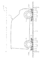
図1〜図4は本発明の実施に用いる車両の搬送装置の形態の一例を示すものである。1は車両であり、駆動車輪2により前後方向に自走可能で且つ車両1下部に進入可能な二台の把持台車3(前側台車3a、後側台車3b)に、車両1の前輪1a又は後輪1bをリフトアップするリフター4を設けている。前記二台の把持台車3は、互いに独立に走行するようになっている。 1 to 4 show an example of the form of a carrier device for a vehicle used for carrying out the present invention. Reference numeral 1 denotes a vehicle. Two gripping carriages 3 (a front carriage 3a and a rear carriage 3b) that can travel in the front-rear direction by a drive wheel 2 and can enter the lower portion of the vehicle 1 are attached to the front wheels 1a or the rear wheels of the vehicle 1. A lifter 4 that lifts up the wheel 1b is provided. The two gripping carriages 3 run independently of each other.

前記二台の把持台車3(前側台車3a、後側台車3b)は、図1、図2に示す如く、台車本体5の両側面に、前側アーム6と後側アーム7の各一対の把持アームを備えた構成をそれぞれ有しており、この計二対の把持アームによって左右二基のリフター4を形成している。このリフター4により、前側台車3aと後側台車3bで車両1の前輪1aと後輪1bをそれぞれ支持し、駆動車輪2を駆動することで前側台車3aと後側台車3bを自走させ、車両1を所定の場所へ搬送するようになっている。   As shown in FIGS. 1 and 2, each of the two gripping carriages 3 (front carriage 3a and rear carriage 3b) has a pair of gripping arms of a front arm 6 and a rear arm 7 on both sides of the carriage body 5. And the left and right lifters 4 are formed by a total of two pairs of gripping arms. The lifter 4 supports the front wheel 1a and the rear wheel 1b of the vehicle 1 by the front bogie 3a and the rear bogie 3b, respectively, and drives the drive wheels 2 to make the front bogie 3a and the rear bogie 3b self-propelled. 1 is conveyed to a predetermined place.

ここで、車両1の搬送にあたっては、予め把持台車3の設置された所定の場所やその付近に車両1を移動させた上で、車両1に対し把持台車3を動作させ、必要に応じて車両1も動かしながら、把持台車3上に車両1を支持させることが必要になる。また、場合によっては、把持台車3上に支持された状態の車両1を一定のスペース内に留め置くことも必要になる。以下、本明細書中では、車両1を把持台車3上に支持し、また留め置くためのスペースを「支持操作区画」と呼ぶものとする。   Here, when the vehicle 1 is transported, the vehicle 1 is moved in advance to a predetermined place where the gripping carriage 3 is installed or in the vicinity thereof, and then the gripping carriage 3 is operated with respect to the vehicle 1 and, if necessary, the vehicle. It is necessary to support the vehicle 1 on the gripping carriage 3 while moving 1 as well. In some cases, it is necessary to keep the vehicle 1 supported on the gripping carriage 3 in a fixed space. Hereinafter, in the present specification, a space for supporting and holding the vehicle 1 on the gripping carriage 3 is referred to as a "support operation section".

車両1の搬送を行う場所が例えば工場や車両の試験設備、あるいは倉庫式の駐車場等であれば、床面上に備えた前後二台の把持台車3で車両1を支持し、そのまま前記二台の把持台車3を床面上で自走させて目的の場所まで搬送する場合が想定される。この場合、前記支持操作区画は床面上の所定のスペースである。また、搬送を行う場所が立体式の駐車場等であれば、パレット上に車両1を積載して移動する形式の搬送機械等が備えられており、前記パレットと、それ以外の床面との間で把持台車3を用いて車両1を搬送することが考えられる。この場合には、前記支持操作区画は前記パレット、もしくは該パレットを含む周辺の領域であると言うことができる。図1では、パレットP上の把持台車3に車両1を支持した状態を図示している。   If the place where the vehicle 1 is transported is, for example, a factory, a vehicle test facility, a warehouse-type parking lot, or the like, the vehicle 1 is supported by two front and rear gripping carriages 3 provided on the floor surface, and the two vehicles are directly supported. It is assumed that the gripping cart 3 of the platform is self-propelled on the floor surface and is transported to a target place. In this case, the support operation section is a predetermined space on the floor surface. Further, if the place where the transportation is carried out is a three-dimensional parking lot or the like, a transportation machine of a type in which the vehicle 1 is loaded on a pallet and moved is provided, and the pallet and the other floor surface It is conceivable to transport the vehicle 1 by using the gripping carriage 3 between them. In this case, it can be said that the support operation section is the pallet or a peripheral area including the pallet. FIG. 1 illustrates a state in which the vehicle 1 is supported by the gripping carriage 3 on the pallet P.

図2〜図4を参照して各把持台車3の構成を説明する。台車本体5は、図2に示す如く、左右方向中央に位置して駆動車輪2を備えた駆動フレーム8と、リフター4を備えて台車本体5の両側面をなすリフトフレーム9とを、連結部材10により連結してなる。   The configuration of each gripping carriage 3 will be described with reference to FIGS. As shown in FIG. 2, the carriage main body 5 includes a drive frame 8 that is provided at the center in the left-right direction and that includes the drive wheels 2, and a lift frame 9 that includes the lifter 4 and that forms both side surfaces of the carriage main body 5. It is connected by 10.

二組のリフター4を構成する前記四本の把持アーム(前側アーム6,6、後側アーム7,7)は、それぞれリフトフレーム9に水平方向に回動自在に取り付けられており、台車本体5の側面に沿う格納位置(実線で示す位置)と、該格納位置から側方に張り出して車両1の各車輪(前輪1a又は後輪1b)をそれぞれ前後から挟み付けるように支持しつつリフトアップする展開位置(仮想線で示す位置)との間で回動するようになっている。   The four gripping arms (the front arms 6 and 6 and the rear arms 7 and 7) forming the two sets of lifters 4 are attached to the lift frame 9 so as to be rotatable in the horizontal direction. And a storage position (position indicated by a solid line) along a side surface of the vehicle and a lift-up while supporting each wheel of the vehicle 1 (front wheel 1a or rear wheel 1b) from the front and rear so as to project laterally from the storage position. It is adapted to rotate with respect to a deployed position (position indicated by a virtual line).

前記四本の把持アームの回動は、リフトフレーム9に備えたアーム回動機構11によって駆動される。本例の場合、アーム回動機構11は、前記各把持アーム(前側アーム6、後側アーム7)と台車本体5側との間を掛け渡すように取り付けた油圧シリンダ11として構成されている。各油圧シリンダ11は、シリンダ本体11aの基端部がリフトフレーム9に、ロッド11bの先端部が前記各把持アームの途中に、それぞれ回動自在に取り付けられている。そして、油圧シリンダ11が収縮することにより、前記各把持アームが格納位置に回動し、油圧シリンダ11が伸長することにより、前記各把持アームが展開位置に回動するようになっている。 The rotation of the four gripping arms is driven by an arm rotating mechanism 11 provided on the lift frame 9. In the case of this example , the arm rotation mechanism 11 is configured as a hydraulic cylinder 11 mounted so as to bridge between the respective gripping arms (the front arm 6 and the rear arm 7) and the trolley body 5 side. Each hydraulic cylinder 11 is rotatably attached to the lift frame 9 at the base end of the cylinder body 11a and at the middle of each gripping arm at the tip end of the rod 11b. When the hydraulic cylinder 11 contracts, the gripping arms rotate to the storage position, and when the hydraulic cylinder 11 extends, the gripping arms rotate to the deployed position.

尚、図2に示した例では、前記四本の各把持アームにそれぞれ油圧シリンダ11が備えられているので、前記各把持アームを一本ずつ独立に動作させることができるが、必ずしもこのようになっていなくても良い。一台の把持台車3において二組のリフター4を構成する前記各把持アームのうち、二本の前側アーム6,6と、二本の後側アーム7,7は、それぞれ同時に動作するよう構成されていても良い。図3は、リフター4をそのように構成した場合のリフター4周辺の配置の一例を示しており、左右の前側アーム6,6間にアーム回動機構としての油圧シリンダ11を掛け渡し、シリンダ本体11aの基端部を一方の前側アーム6に、ロッド11bの先端部を他方の前側アーム6に、それぞれ回動自在に取り付けている。同様に、左右の後側アーム7,7間に油圧シリンダ11を掛け渡し、シリンダ本体11aの基端部を一方の後側アーム7に、ロッド11bの先端部を他方の後側アーム7に、それぞれ回動自在に取り付けている。このようにすると、油圧シリンダ11が収縮することによって前記各把持アームが格納位置(実線で示す位置)に回動し、油圧シリンダ11が伸長することによって前記各把持アームが展開位置(仮想線で示す位置)に回動するが、二本の前側アーム6,6の間、及び二本の後側アーム7,7の間でそれぞれ油圧シリンダ11を兼用しているので、二本の前側アーム6,6は同時に動作し、二本の後側アーム7,7も同時に動作する。ただし、前側アーム6,6と、後側アーム7,7とは、互いに独立に動作するようになっている。   In the example shown in FIG. 2, since each of the four gripping arms is provided with the hydraulic cylinder 11, it is possible to independently operate each of the gripping arms, but this is not always the case. It doesn't have to be. Of the gripping arms that compose the two sets of lifters 4 in one gripping carriage 3, the two front arms 6 and 6 and the two rear arms 7 and 7 are configured to operate simultaneously, respectively. It may be. FIG. 3 shows an example of the layout of the lifter 4 and its surroundings when the lifter 4 is configured as such. A hydraulic cylinder 11 as an arm rotating mechanism is laid between the left and right front arms 6 and 6, and the cylinder body is The base end of 11a is rotatably attached to one front arm 6, and the tip of the rod 11b is rotatably attached to the other front arm 6. Similarly, the hydraulic cylinder 11 is spanned between the left and right rear arms 7, 7 so that the base end of the cylinder body 11a is one rear arm 7 and the tip of the rod 11b is the other rear arm 7. Each is rotatably attached. In this case, the hydraulic cylinders 11 contract to rotate the gripping arms to the storage positions (positions indicated by solid lines), and the hydraulic cylinder 11 extends to expand the gripping arms to positions (imaginary lines). Although it rotates to the position (shown), the two front arms 6 and 6 and the two rear arms 7 and 7 also serve as hydraulic cylinders 11, respectively. , 6 operate simultaneously, and the two rear arms 7, 7 also operate simultaneously. However, the front arms 6 and 6 and the rear arms 7 and 7 operate independently of each other.

また、アーム回動機構11の構成はここに示した油圧シリンダに限定されない。油圧シリンダに代えて電動シリンダを採用しても良いし、ギヤを用いた装置としても良い。その他、前側アーム6や後側アーム7が上記した動作を行うよう構成される限りにおいて、各種の機構を採用し得る。   Further, the configuration of the arm rotating mechanism 11 is not limited to the hydraulic cylinder shown here. An electric cylinder may be used instead of the hydraulic cylinder, or a device using gears may be used. In addition, various mechanisms can be adopted as long as the front arm 6 and the rear arm 7 are configured to perform the above-described operation.

台車本体5の複数所要箇所、及び、前記各把持アームの先端には、車両1の荷重を支持するキャスタ12が取り付けてある。   Casters 12 for supporting the load of the vehicle 1 are attached to a plurality of required portions of the carriage main body 5 and to the tips of the gripping arms.

連結部材10は、図4に示す如く、リフトフレーム9に設けられ且つ上下方向へ延びるピン10aと、駆動フレーム8に設けられ且つピン10aに嵌装されるブラケット10bとから構成され、リフトフレーム9に備えたリフター4に加わる車両1(図1参照)の荷重を、駆動フレーム8に備えた駆動車輪2に伝えないよう構成してある。尚、ピン10aをリフトフレーム9の代わりに駆動フレーム8に設け、ピン10aに嵌装されるブラケット10bを駆動フレーム8の代わりにリフトフレーム9に設けて連結部材10を構成することも可能である。   As shown in FIG. 4, the connecting member 10 includes a pin 10 a provided on the lift frame 9 and extending in the vertical direction, and a bracket 10 b provided on the drive frame 8 and fitted to the pin 10 a. The load of the vehicle 1 (see FIG. 1) applied to the lifter 4 provided in the drive frame 8 is not transmitted to the drive wheels 2 provided in the drive frame 8. The pin 10a may be provided on the drive frame 8 instead of the lift frame 9, and the bracket 10b fitted to the pin 10a may be provided on the lift frame 9 instead of the drive frame 8 to configure the connecting member 10. .

前側台車3a、後側台車3bの所要箇所には、前側台車3a又は後側台車3bに対する車両1の位置を検出するための位置センサ13が備えられる。   Position sensors 13 for detecting the position of the vehicle 1 with respect to the front carriage 3a or the rear carriage 3b are provided at required positions of the front carriage 3a and the rear carriage 3b.

図2に示した例では、位置センサ13は、把持台車3の側方一箇所に備えた光センサとして構成されており、その取り付け位置はリフター4の前側アーム6と後側アーム7の間である。接近する車輪(前輪1aまたは後輪1b)をこの位置から検出することにより、把持台車3に対する車両1(図1参照)の位置を検出するようになっている。   In the example shown in FIG. 2, the position sensor 13 is configured as an optical sensor provided on one side of the gripping carriage 3, and its mounting position is between the front arm 6 and the rear arm 7 of the lifter 4. is there. By detecting the approaching wheel (front wheel 1a or rear wheel 1b) from this position, the position of the vehicle 1 (see FIG. 1) with respect to the gripping carriage 3 is detected.

尚、位置センサ13の構成や配置は、ここで示した例に限定されない。例えば、位置センサ13として光センサの代わりに超音波センサ等を用いても、同様に車両1の位置を検出することができる。また、前側アーム6を回動させる油圧シリンダ11に備えた油圧センサとして位置センサ13を構成し、展開位置にある前側アーム6に前輪1aや後輪1bが接触したことを油圧シリンダ11内の油圧の変化として検知することもできる。アーム回動機構として、油圧シリンダ11の代わりに電動シリンダを採用する場合には、該電動シリンダを駆動するモータの負荷を検出するセンサとして位置センサ13を構成することもできる。また、複数の形式の位置センサ13を組み合わせても良く、例えば、前側台車3aには油圧シリンダ11の油圧センサである位置センサ13を備え、後側台車3bの側面には光センサである位置センサ13を備えるようにしても良い。   The configuration and arrangement of the position sensor 13 are not limited to the example shown here. For example, even if an ultrasonic sensor or the like is used as the position sensor 13 instead of the optical sensor, the position of the vehicle 1 can be similarly detected. In addition, the position sensor 13 is configured as a hydraulic pressure sensor provided in the hydraulic cylinder 11 that rotates the front arm 6, and the fact that the front wheel 1a or the rear wheel 1b is in contact with the front arm 6 in the deployed position is controlled by the hydraulic pressure in the hydraulic cylinder 11. Can also be detected as a change in When an electric cylinder is used instead of the hydraulic cylinder 11 as the arm rotating mechanism, the position sensor 13 can be configured as a sensor that detects the load of the motor that drives the electric cylinder. Further, a plurality of types of position sensors 13 may be combined, for example, the front carriage 3a is provided with a position sensor 13 which is a hydraulic sensor of the hydraulic cylinder 11, and the rear carriage 3b is provided with a position sensor which is an optical sensor on a side surface thereof. 13 may be provided.

必要な位置センサ13の数は、後述する把持台車3の作動手順によって変わり得る。前側台車3aと後側台車3bの両方に位置センサ13が必要な場合もあれば、後側台車3bのみに設置すれば十分な場合もある。また、位置センサ13の設置が不要な場合もある。   The number of required position sensors 13 may vary depending on the operating procedure of the gripping carriage 3 described later. In some cases, the position sensor 13 may be required for both the front carriage 3a and the rear carriage 3b, or in some cases it may be sufficient to install the position sensor 13 only in the rear carriage 3b. In some cases, it is not necessary to install the position sensor 13.

あるいは、位置センサ13を把持台車3上に備えるのではなく、例えば図1に示す如く、支持操作区画や周囲の設備側に備え、車両1の位置を周囲から監視するよう構成しても良い。この場合、位置センサ13の構成は光センサや超音波センサとしても良いし、例えば、車両1や把持台車3の映像をカメラ等で撮影し、画像処理により車両1の位置を判別する装置とすることもできる。   Alternatively, instead of providing the position sensor 13 on the gripping carriage 3, for example, as shown in FIG. 1, the position sensor 13 may be provided in the supporting operation section or the surrounding facility side to monitor the position of the vehicle 1 from the surroundings. In this case, the configuration of the position sensor 13 may be an optical sensor or an ultrasonic sensor, and for example, a device for photographing the image of the vehicle 1 or the gripping carriage 3 with a camera or the like and determining the position of the vehicle 1 by image processing. You can also

位置センサ13は、上記したような種々の構成のものを組み合わせ、あるいは使い分けることにより、把持台車3に対する車両1の位置だけでなく、支持操作区画における車両1の位置も検出するよう構成することができる。いずれにしても、位置センサ13は後述する把持台車3の作動を実行できる構成と配置になっていれば良い。必要とされる位置センサ13の構成や配置については、把持台車3の作動手順とあわせて後段で詳述する。   The position sensor 13 may be configured to detect not only the position of the vehicle 1 with respect to the gripping carriage 3 but also the position of the vehicle 1 in the support operation section by combining or using the various configurations as described above. it can. In any case, it suffices that the position sensor 13 be configured and arranged so as to execute the operation of the gripping carriage 3 described later. The required configuration and arrangement of the position sensor 13 will be described in detail later along with the operation procedure of the gripping carriage 3.

台車本体5の駆動フレーム8には、駆動車輪2の駆動や油圧シリンダ11の伸縮を制御する駆動制御部14を備えている。駆動制御部14による制御系のブロック図の一例を図5に示す。   The drive frame 8 of the trolley body 5 is provided with a drive control unit 14 that controls the drive of the drive wheels 2 and the expansion and contraction of the hydraulic cylinder 11. FIG. 5 shows an example of a block diagram of a control system by the drive control unit 14.

駆動制御部14は、駆動車輪2(図1〜図4参照)のモータ2a及びブレーキ2bを介し、駆動車輪2の駆動と制動を行う。これにより、各把持台車3自体の床面に対する動きを制御するようになっている。   The drive controller 14 drives and brakes the drive wheel 2 via the motor 2a and the brake 2b of the drive wheel 2 (see FIGS. 1 to 4). Thus, the movement of each gripping carriage 3 itself with respect to the floor surface is controlled.

把持台車3の所要位置には台車移動センサ15が備えられており、把持台車3の移動速度や移動距離を検出するようになっている。台車移動センサ15は、例えば、駆動車輪2(図1〜図4参照)のモータ2aに取り付けられた回転センサとして構成することができる。尚、位置センサ13の構成や取付位置によっては、この台車移動センサ15の機能は位置センサ13が兼ねるようにすることもできる。   A carriage movement sensor 15 is provided at a required position of the gripping carriage 3 so as to detect the moving speed and the moving distance of the gripping carriage 3. The carriage movement sensor 15 can be configured as, for example, a rotation sensor attached to the motor 2a of the drive wheel 2 (see FIGS. 1 to 4). The position sensor 13 may have the function of the carriage movement sensor 15 depending on the configuration and mounting position of the position sensor 13.

駆動制御部14は、回動制御部11cを介し、前側アーム6及び後側アーム7を構成するアーム回動機構(油圧シリンダ)11(図1〜図4参照)の動作を行う。回動制御部11cは、例えば、油圧回路に油圧モータを備えた油圧配管系統により油圧シリンダ11への圧油の給排を行う油圧ユニット11cとして構成され、油圧により前記把持アームの回動を制御するようになっている。油圧ユニット11cは、上述の如く、前側アーム6の油圧シリンダ11と、後側アーム7の油圧シリンダ11を互いに独立に動かすことができるようになっている。   The drive control unit 14 operates the arm rotation mechanism (hydraulic cylinder) 11 (see FIGS. 1 to 4) forming the front arm 6 and the rear arm 7 via the rotation control unit 11c. The rotation control unit 11c is configured as, for example, a hydraulic unit 11c that supplies and discharges pressure oil to and from the hydraulic cylinder 11 by a hydraulic piping system including a hydraulic motor in a hydraulic circuit, and controls the rotation of the gripping arm by hydraulic pressure. It is supposed to do. As described above, the hydraulic unit 11c can move the hydraulic cylinder 11 of the front arm 6 and the hydraulic cylinder 11 of the rear arm 7 independently of each other.

尚、上記したように、アーム回動機構11として油圧シリンダの代わりに電動シリンダを採用したり、ギヤを介した駆動機構により前記四本の把持アームを駆動することも可能であるが、この場合、回動制御部11cは前記電動シリンダや前記駆動機構と前記バッテリーとを電気配線にて接続した装置として構成される。このように、回動制御部11cは、アーム回動機構11の構成に応じた種々の構成を取り得る。   As described above, an electric cylinder may be used as the arm rotating mechanism 11 instead of the hydraulic cylinder, or the four gripping arms may be driven by a driving mechanism via gears. In this case, The rotation control unit 11c is configured as a device in which the electric cylinder or the drive mechanism and the battery are connected by electrical wiring. As described above, the rotation control unit 11c can have various configurations according to the configuration of the arm rotation mechanism 11.

さらに、アーム回動機構11には、各把持アームの展開位置への回動完了に合わせて展開確認信号16aを発信する展開確認センサ16、各把持アームの格納位置への回動完了に合わせて格納確認信号17aを発信する格納確認センサ17が備えられている。展開確認信号16aや格納確認信号17aは駆動制御部14に入力され、駆動制御部14は、展開確認信号16aや格納確認信号17aの入力に応じてアーム回動機構(油圧シリンダ)11の作動を停止するようになっている。   Further, the arm rotation mechanism 11 includes a deployment confirmation sensor 16 which outputs a deployment confirmation signal 16a in accordance with the completion of rotation of each gripping arm to the deployment position, and a completion of rotation of each gripping arm to the storage position. A storage confirmation sensor 17 for transmitting a storage confirmation signal 17a is provided. The expansion confirmation signal 16a and the storage confirmation signal 17a are input to the drive control unit 14, and the drive control unit 14 operates the arm rotation mechanism (hydraulic cylinder) 11 in response to the input of the development confirmation signal 16a and the storage confirmation signal 17a. It is supposed to stop.

位置センサ13からは、位置信号13aが駆動制御部14に対して入力されるようになっている。   The position signal 13 a is input from the position sensor 13 to the drive control unit 14.

その他、把持台車3には、油圧ユニット11cの油圧モータ、駆動車輪2のモータ2a等に通電を行う鉛蓄電池等のバッテリー(図示せず)等、把持台車3を構成する機器の動作に必要な各種の装置や機構を備えている。   In addition, the gripping trolley 3 is necessary for the operation of the devices constituting the gripping trolley 3, such as a hydraulic motor of the hydraulic unit 11c, a battery (not shown) such as a lead storage battery for energizing the motor 2a of the driving wheel 2, and the like. It is equipped with various devices and mechanisms.

前後の把持台車3a,3bの外部には、該把持台車3a,3bの動作全体を制御する管制用制御機器18が備えられている。管制用制御機器18は、前後の把持台車3a,3bの駆動制御部14と通信し、前後の把持台車3a,3bを連携させながら各把持台車3a,3bに備えた駆動車輪2やアーム回動機構11の動作を制御するようになっている。管制用制御機器18は、使用者からの搬送許可信号18aの入力を受けて所定の動作を行うように構成しても良い。   Outside the front and rear gripping carriages 3a and 3b, there is provided a control device 18 for control that controls the entire operation of the gripping carriages 3a and 3b. The control device 18 for control communicates with the drive control unit 14 of the front and rear gripping trolleys 3a and 3b, and cooperates with the front and rear gripping trolleys 3a and 3b to drive the drive wheels 2 and arm rotations provided on the respective gripping trolleys 3a and 3b. The operation of the mechanism 11 is controlled. The control device 18 for control may be configured to perform a predetermined operation in response to the input of the transportation permission signal 18a from the user.

次に、上記した車両の搬送装置による車両の搬送方法を説明する。   Next, a method of transporting a vehicle by the above-described vehicle transport device will be described.

図6〜図8は上記した把持台車3を用いた車両1の搬送方法の一例(第一参考例)を説明するものである。ここでは、パレットPを備えた立体駐車場等の設備の支持操作区画において、二台の把持台車3により、パレットPの外からパレットP上へ車両1を搬送する場合を例に説明する。尚、パレットPは本発明において必須の構成でなく、パレットPを備えない設備においても上の如き車両の搬送装置を使用し得ることは上述した通りであり、以下に説明する搬送手順はパレットPがなくとも成立する(後の図9〜図11、図12〜図14及び図15〜図17で説明する搬送手順においても同様である)。 6 to 8 illustrate an example ( first reference example) of the method of transporting the vehicle 1 using the above-described gripping carriage 3. Here, a case where the vehicle 1 is transported from the outside of the pallet P onto the pallet P by the two gripping carriages 3 in the support operation section of equipment such as a multi-story parking lot equipped with the pallet P will be described. Incidentally, the pallet P is not essential in the present invention is as it is described above that may be used to transport device such as a vehicle above the equipment without the pallet P, the conveying steps pallet P to be described below It is established even if there is not (the same applies to the transfer procedure described later in FIGS. 9 to 11, 12 to 14 and 15 to 17).

車両1を搬送する際には、まず、ステップS1として(図6参照)、図7(a)に示す如く、パレットP上に配置した前側台車3a、後側台車3bの後方に、車両1を位置させる。すなわち、車両1、後側台車3b、前側台車3aの順に配置する。このとき、リフター4は、前側台車3aにおいては前側アーム6が展開位置に回動し、後側アーム7が格納位置に回動した状態であり、後側台車3bにおいては前側アーム6と後側アーム7のいずれもが格納位置に回動した状態である。前側台車3aと後側台車3bは、前側台車3aのリフター4と後側台車3bのリフター4の間隔が車両1のホイールベース以下となるよう配置されている。前側台車3aの駆動車輪2は自由に回転する状態となっており、後側台車3bの駆動車輪2はロックされている。   When carrying the vehicle 1, first, as step S1 (see FIG. 6), as shown in FIG. 7 (a), the vehicle 1 is placed behind the front carriage 3a and the rear carriage 3b arranged on the pallet P. Position it. That is, the vehicle 1, the rear carriage 3b, and the front carriage 3a are arranged in this order. At this time, the lifter 4 is in a state in which the front arm 6 is rotated to the deployed position and the rear arm 7 is rotated to the storage position in the front carriage 3a, and the rear arm 3 and the rear arm 7 are rotated in the rear carriage 3b. Each of the arms 7 is in a state of being rotated to the storage position. The front bogie 3a and the rear bogie 3b are arranged such that the distance between the lifter 4 of the front bogie 3a and the lifter 4 of the rear bogie 3b is less than or equal to the wheel base of the vehicle 1. The drive wheels 2 of the front carriage 3a are in a freely rotating state, and the drive wheels 2 of the rear carriage 3b are locked.

この状態から、ステップS2として(図6参照)、車両1を前方に位置する二台の把持台車3に向かって進行させていく。図7(b)に示す如く、車両1の前輪1aが後側台車3bに備えたリフター4の側方に到達すると、この位置に備えた位置センサ13により、車両1がこの位置に到達したことが検知される。尚、この位置センサ13としては、例えば光センサや超音波センサを想定している。   From this state, as step S2 (see FIG. 6), the vehicle 1 is advanced toward the two gripping carriages 3 located in the front. As shown in FIG. 7B, when the front wheel 1a of the vehicle 1 reaches the side of the lifter 4 provided on the rear carriage 3b, the position sensor 13 provided at this position indicates that the vehicle 1 has reached this position. Is detected. As the position sensor 13, for example, an optical sensor or an ultrasonic sensor is assumed.

図7(c)に示す如く、車両1がさらに前進し、前輪1aが後側台車3bに備えたリフター4の位置を通り過ぎると、通り過ぎたことが位置センサ13によって検知される。   As shown in FIG. 7C, when the vehicle 1 further advances and the front wheels 1a pass the position of the lifter 4 provided on the rear carriage 3b, the position sensor 13 detects the passing.

後側台車3bの位置センサ13が車両1の通過を検知したことは、位置信号13aとして後側台車3bの駆動制御部14に入力される(図5参照)。位置信号13aの入力を受けた駆動制御部14は、ステップS3として(図6参照)、後側台車3bの油圧シリンダ11を駆動し、図8(d)に示す如く、前側アーム6を展開位置に回動させる。   The fact that the position sensor 13 of the rear carriage 3b has detected the passage of the vehicle 1 is input to the drive control unit 14 of the rear carriage 3b as a position signal 13a (see FIG. 5). In response to the input of the position signal 13a, the drive control unit 14 drives the hydraulic cylinder 11 of the rear carriage 3b in step S3 (see FIG. 6) to move the front arm 6 to the expanded position as shown in FIG. 8 (d). Rotate to.

ステップS4として(図6参照)、車両1をさらに前進させる。ここでは車両1を、前輪1aが前側台車3aの側方に達し、前側台車3a側方の展開位置にある前側アーム6に当接するまで前進させる。   As step S4 (see FIG. 6), the vehicle 1 is further advanced. Here, the vehicle 1 is moved forward until the front wheel 1a reaches the side of the front carriage 3a and comes into contact with the front arm 6 in the deployed position on the side of the front carriage 3a.

続けて、ステップS5として(図6参照)、前輪1aが前側台車3aの前側アーム6に当接した状態で、車両1をさらに前進させる。上記したように前側台車3aの駆動車輪2は自由に回転する状態となっているので、前側台車3aは、前輪1aに前側アーム6を押され、車両1の動きに追従して前方に移動する。   Subsequently, as step S5 (see FIG. 6), the vehicle 1 is further advanced in a state where the front wheel 1a is in contact with the front arm 6 of the front carriage 3a. As described above, since the drive wheels 2 of the front bogie 3a are in a freely rotating state, the front bogie 3a moves forward as the front wheel 1a pushes the front arm 6 to follow the movement of the vehicle 1. .

車両1の前進を続けると、図8(e)に示す如く、後輪1bが後側台車3bのリフター4の側方に到達し、展開位置にある前側アーム6に当接する。上記したように、後側台車3bの駆動車輪2はロックしており、後側台車3b側方の展開位置にある前側アーム6が車輪止めとして機能するので、車両1は後輪1bの前進を阻まれ、この位置より前方には進まない。またこの時、後輪1bが後側台車3bのリフター4の側方に到達した際に前側台車3aの駆動車輪2をロックし、前側台車3aの前側アーム6が車輪止めとなるようにしても良い。車両1は、この位置で停車させる。   When the vehicle 1 continues to move forward, as shown in FIG. 8 (e), the rear wheel 1b reaches the side of the lifter 4 of the rear carriage 3b and comes into contact with the front arm 6 in the deployed position. As described above, the drive wheels 2 of the rear carriage 3b are locked, and the front arm 6 in the deployed position on the side of the rear carriage 3b functions as a wheel stopper, so that the vehicle 1 moves the rear wheels 1b forward. It will be blocked and you will not move forward from this position. Further, at this time, when the rear wheel 1b reaches the side of the lifter 4 of the rear carriage 3b, the drive wheels 2 of the front carriage 3a are locked so that the front arm 6 of the front carriage 3a serves as a wheel stopper. good. The vehicle 1 is stopped at this position.

車両1がこの位置に達したことは、後側台車3bの側方に備えた位置センサ13によって検知され、位置信号13aとして後側台車3bの駆動制御部14に入力される(図5参照)。駆動制御部14は、後側台車3bの駆動制御部14への位置信号13aの入力に応じて次のステップS6の動作を行う(図6参照)。あるいはここで、車両1から降りた運転者が管制用制御機器18に搬送許可信号18aを入力し(図5参照)、該搬送許可信号18aの入力に応じて次のステップS6の動作を行うようにしても良い。もしくは、前側台車3aの移動距離を台車移動センサ(回転センサ)15(図5参照)を監視することで検知し、前側台車3aが所定の距離を移動したところでステップS6の動作を行うようにしても良い。   The fact that the vehicle 1 has reached this position is detected by a position sensor 13 provided on the side of the rear carriage 3b, and is input to the drive control unit 14 of the rear carriage 3b as a position signal 13a (see FIG. 5). . The drive control unit 14 performs the operation of the next step S6 in response to the input of the position signal 13a to the drive control unit 14 of the rear carriage 3b (see FIG. 6). Alternatively, here, the driver getting off the vehicle 1 inputs the transportation permission signal 18a to the control device 18 for control (see FIG. 5), and performs the operation of the next step S6 in response to the input of the transportation permission signal 18a. You can Alternatively, the movement distance of the front carriage 3a is detected by monitoring the carriage movement sensor (rotation sensor) 15 (see FIG. 5), and the operation of step S6 is performed when the front carriage 3a has moved a predetermined distance. Is also good.

前後の把持台車3a,3bの駆動制御部14は、ステップS6として(図6参照)、油圧シリンダ11を駆動し、図8(f)に示す如く、それぞれの後側アーム7を展開位置に回動させる。両把持台車3a,3bのリフター4はそれぞれ、車両1の前輪1a又は後輪1bを、前側アーム6と後側アーム7の間で前後から挟み付けるように支持しつつリフトアップする。   The drive control unit 14 of the front and rear gripping carriages 3a and 3b drives the hydraulic cylinder 11 in step S6 (see FIG. 6) to rotate each rear arm 7 to the deployed position as shown in FIG. 8 (f). To move. The lifters 4 of both gripping carts 3a and 3b lift up while supporting the front wheel 1a or the rear wheel 1b of the vehicle 1 so as to be sandwiched between the front arm 6 and the rear arm 7 from the front and rear.

すなわち、車両1のリフトアップに先立って車両1を前後の把持台車3に対して進入させる際、前側台車3aの後側アーム7は格納位置に回動させて前輪1aの間を通過させつつ、前側アーム6は展開位置に回動させて前輪1aに当接させることで、前輪1aに対して前側台車3aを位置決めするようになっている。同様に、後側台車3bの後側アーム7は格納位置に回動させて後輪1bの間を通過させつつ、前側アーム6は前輪1aが通過したタイミングで展開位置に回動させ、のちに後輪1bと当接させることで、後輪1bに対して後側台車3bを位置決めするようになっている。そして、各把持台車3を車両1に対して位置決めした後、各把持台車3の後側アーム7を展開位置に回動させて車両1をリフトアップするようにしている。   That is, when the vehicle 1 is advanced into the front and rear gripping carriages 3 before the vehicle 1 is lifted up, the rear arm 7 of the front carriage 3a is rotated to the retracted position to pass between the front wheels 1a, By rotating the front arm 6 to the deployed position and contacting the front wheel 1a, the front carriage 3a is positioned with respect to the front wheel 1a. Similarly, the rear arm 7 of the rear carriage 3b is pivoted to the retracted position so as to pass between the rear wheels 1b, while the front arm 6 is pivoted to the deployed position at the timing when the front wheel 1a passes, and then, By contacting the rear wheel 1b, the rear carriage 3b is positioned with respect to the rear wheel 1b. Then, after positioning each gripping carriage 3 with respect to the vehicle 1, the rear arm 7 of each gripping carriage 3 is rotated to the deployed position to lift up the vehicle 1.

この後、車両1を支持した前後二台の把持台車3ごとパレットPを移動させる。車両1をパレットP上に載せた状態で格納する場合は、把持台車3にリフトアップされた状態の車両1をパレットPに積載したまま、格納先へ移動させれば良い。または、パレットP上に車両1を搬送した後、リフター4の前側アーム6及び後側アーム7を格納位置に回動させ、車両1の前輪1a、後輪1bをリフトアップした状態からパレットP上に降ろす。続いて、二台の把持台車3を車両1下部から引き出し、パレットP上に把持台車3を介さず車両1を直接積載した状態で、パレットPを格納先へ移動させる。   After that, the pallet P is moved together with the two front and rear gripping carts 3 supporting the vehicle 1. When the vehicle 1 is stored while being placed on the pallet P, the vehicle 1 lifted up by the gripping carriage 3 may be moved to the storage destination while being loaded on the pallet P. Alternatively, after transporting the vehicle 1 onto the pallet P, the front arm 6 and the rear arm 7 of the lifter 4 are rotated to the retracted position, and the front wheels 1a and the rear wheels 1b of the vehicle 1 are lifted up from the pallet P top. Take it down. Subsequently, the two gripping carts 3 are pulled out from the lower portion of the vehicle 1, and the pallet P is moved to the storage destination while the vehicle 1 is directly loaded on the pallet P without the gripping cart 3 interposed therebetween.

車両1をパレットPで搬送した後、該パレットPの外の格納位置に格納する場合には、把持台車3にリフトアップされた状態の車両1ごとパレットPを移動させた後、車両1をリフトアップしたままの状態で駆動車輪2を駆動して両把持台車3を自走させ、車両1をパレットPの外に搬送する。そして、車両1が搭載された前後二台の把持台車3を搬送すべき所定の位置へ移動させ、リフター4の前側アーム6及び後側アーム7を格納位置に回動させ、車両1の前輪1a、後輪1bをリフトアップした状態から床面上に降ろす。続いて、二台の把持台車3を車両1下部から引き出してパレットP上に戻し、車両1の搬送が完了する。   When the vehicle 1 is transported by the pallet P and then stored in a storage position outside the pallet P, the pallet P is moved together with the vehicle 1 in a state of being lifted up by the gripping carriage 3, and then the vehicle 1 is lifted. The drive wheels 2 are driven in the state where the vehicle 1 is kept up to allow both gripping carts 3 to travel by themselves, and the vehicle 1 is transported to the outside of the pallet P. Then, the front and rear two gripping carts 3 on which the vehicle 1 is mounted are moved to a predetermined position to be transported, and the front arm 6 and the rear arm 7 of the lifter 4 are rotated to the storage position, and the front wheel 1a of the vehicle 1 is moved. , The rear wheel 1b is lifted up and then lowered onto the floor surface. Then, the two gripping carts 3 are pulled out from the lower portion of the vehicle 1 and returned onto the pallet P, and the transportation of the vehicle 1 is completed.

倉庫式の駐車場等、パレットPによらず車両1を搬送する設備の場合には、前後二台の把持台車3で車両1をリフトアップした後(図8(f)参照)、そのまま各把持台車3を搬送すべき所定の位置へ移動させ、リフター4の前側アーム6及び後側アーム7を格納位置に回動させ、車両1の前輪1a、後輪1bをリフトアップした状態から床面上に降ろす。続いて、二台の把持台車3を車両1下部から引き出して車両1の搬送が完了する。   In the case of a facility such as a warehouse-type parking lot that conveys the vehicle 1 without using the pallet P, after the vehicle 1 is lifted up by the two front and rear gripping carriages 3 (see FIG. 8F), each gripping is performed as it is. The carriage 3 is moved to a predetermined position to be transported, the front arm 6 and the rear arm 7 of the lifter 4 are rotated to the retracted position, and the front wheels 1a and the rear wheels 1b of the vehicle 1 are lifted up from the floor surface. Take it down. Then, the two gripping carts 3 are pulled out from the lower portion of the vehicle 1 to complete the transportation of the vehicle 1.

尚、上述の搬送手順においては、位置センサ13は後側台車3bのリフター4の位置に取り付けられて車輪の位置を検出する光センサ又は超音波センサである場合を想定しているが、これ以外の構成や配置を採用することもできる。例えば、前側台車3aにも同様の位置センサ13を設置して前側台車3aから前輪1aの位置を検出するようにしても良いし、前側台車3aや後側台車3bの前側アーム6を駆動する油圧シリンダ11の油圧(油圧シリンダ11ではなく電動シリンダ等を採用している場合には、該電動シリンダのモータの負荷)を検出する位置センサ13によって、前輪1aや後輪1bの前側アーム6への接触を検出するようにしても良い。また、周囲の設備に備えて車両1の位置を周囲から監視するよう構成した位置センサ13(例えば、図1参照)によって上記搬送手順を実行しても良い。いずれにしても、上記した前側台車3aや後側台車3bの動作を実行できるよう、適切なタイミングで車両1の位置を検出するよう構成されていれば良い。   In addition, in the above-described transportation procedure, it is assumed that the position sensor 13 is an optical sensor or an ultrasonic sensor that is attached to the position of the lifter 4 of the rear carriage 3b and detects the position of the wheel, but other than this. The configuration and arrangement of can also be adopted. For example, a similar position sensor 13 may be installed in the front truck 3a to detect the position of the front wheel 1a from the front truck 3a, or the hydraulic pressure for driving the front arm 6 of the front truck 3a or the rear truck 3b. The position sensor 13 that detects the hydraulic pressure of the cylinder 11 (the load of the motor of the electric cylinder when the hydraulic cylinder 11 is used instead of the hydraulic cylinder 11) is transferred to the front arm 6 of the front wheel 1a or the rear wheel 1b. You may make it detect contact. Further, the transportation procedure may be executed by a position sensor 13 (for example, see FIG. 1) configured to monitor the position of the vehicle 1 from the surroundings in preparation for surrounding facilities. In any case, the position of the vehicle 1 may be detected at an appropriate timing so that the operations of the front bogie 3a and the rear bogie 3b described above can be executed.

上述の搬送手順では、床面上の二台の把持台車3に対して車両1が移動し、前輪1aが前側台車3aに接触した後、車両1の移動に追従して前側台車3aが前方に移動することにより、車両1における車輪の位置に合わせた配置で把持台車3が車輪を支持するようになっている。このため、車両1の搬送にあたって車両1のホイールベースやオーバーハングの影響を受けにくくなっている。   In the above-described transportation procedure, the vehicle 1 moves with respect to the two gripping trolleys 3 on the floor surface, the front wheels 1a contact the front trolley 3a, and then the front trolley 3a moves forward following the movement of the vehicle 1. By moving, the gripping carriage 3 supports the wheels in an arrangement that matches the positions of the wheels in the vehicle 1. Therefore, the transportation of the vehicle 1 is less likely to be affected by the wheel base of the vehicle 1 or an overhang.

すなわち、車両1の搬送や格納にあたって、場合によっては把持台車3上に支持した車両1を一定のスペース内に留め置く必要がある。例えば、パレットPに車両1を積載して搬送する場合には、原則として車両1がパレットPの上からはみ出さないようにしなくてはならないが、ここでパレットP内における車両の搬送装置の位置や、該車両の搬送装置における車輪の支持位置が固定されていると、搬送し得る車両1のホイールベースは前記車両の搬送装置における車輪の支持位置によって固定されてしまう。また、車両1のオーバーハングの範囲も、パレットPの大きさや、該パレットPに対する前記車両の搬送装置の位置によって限定されてしまう。ここで、上に説明した例のように、前輪1a又は後輪1bをそれぞれ支持する前後の把持台車3が互いに独立に作動し、パレットP内における位置や把持台車3同士の位置が自由に動かせるようになっていると、車両1の大きさがパレットP内に収まる範囲内にある限りは、ホイールベースやオーバーハングによらず前後二台の把持台車3によって車両1をパレットP上に適切に積載することができるのである。 That is, when transporting or storing the vehicle 1, it is necessary to keep the vehicle 1 supported on the gripping carriage 3 in a certain space in some cases. For example, when the vehicle 1 is loaded on the pallet P and transported, in principle, the vehicle 1 must be prevented from protruding from the top of the pallet P. Alternatively, if the support position of the wheels in the transfer device of the vehicle is fixed, the wheel base of the vehicle 1 that can be transferred is fixed by the support position of the wheels in the transfer device of the vehicle. Further, the range of the overhang of the vehicle 1 is also limited by the size of the pallet P and the position of the transportation device of the vehicle with respect to the pallet P. Here, as in the example described above, the front and rear gripping carriages 3 that respectively support the front wheels 1a or the rear wheels 1b operate independently of each other, and the positions in the pallet P and the positions of the gripping carriages 3 can be freely moved. Thus, as long as the size of the vehicle 1 is within the range that can be accommodated in the pallet P, the vehicle 1 can be properly placed on the pallet P by the two front and rear gripping carriages 3 regardless of the wheel base and overhang. It can be loaded.

特に、本第一参考例の場合、車両1の前進に追従して前輪1aを支持する前側台車3aが前進するようにしているので、フロントオーバーハングが比較的小さく、リアオーバーハングが大きい車両1や、ホイールベースが大きい車両1をパレットP等、一定のスペース内に収容したい場合に有効である。 Particularly, in the case of the first reference example, since the front bogie 3a supporting the front wheels 1a follows the forward movement of the vehicle 1 so as to move forward, the front overhang is relatively small and the rear overhang is large. Alternatively, it is effective when the vehicle 1 having a large wheel base is to be housed in a fixed space such as the pallet P.

あるいは、支持操作区画における車両1の位置を検出し得る位置センサ13を設置している場合は(図1参照)、図8(f)に示す如く車両1をリフトアップした後、各把持台車3の駆動制御部14を位置センサ13と連携させて作動させ、車両1がパレットP内に収まるよう前後二台の把持台車3を移動させても良い。   Alternatively, when the position sensor 13 capable of detecting the position of the vehicle 1 in the support operation section is installed (see FIG. 1), after the vehicle 1 is lifted up as shown in FIG. The drive control unit 14 may be operated in cooperation with the position sensor 13 to move the two front and rear gripping carriages 3 so that the vehicle 1 is accommodated in the pallet P.

尚、上述の例では、車両1の前方に位置する二台の把持台車3に対して車両1を前進させる場合について説明したが、車両1の後方に位置する把持台車3に対して車両1を後進させるようにしても同様に車両1の搬送を行える(すなわち、図7、図8において、車両1の向きが前後逆となっていても良い)ことは言うまでもない。   In the above example, the case where the vehicle 1 is moved forward with respect to the two gripping carriages 3 positioned in front of the vehicle 1 has been described. It goes without saying that the vehicle 1 can be similarly conveyed even if it is moved backward (that is, the direction of the vehicle 1 may be reversed in FIGS. 7 and 8).

図9〜図11は、停車した車両1に対して二台の把持台車3を動かす場合の車両1の搬送方法の別の一例(第二参考例)を説明するものである。上記第一参考例では、停止している二台の把持台車3に対して車両1を進入させる場合について説明しているが、本第二参考例では、これとは逆に、停車した車両1に対して二台の把持台車3を動かし、車両1の下に潜り込ませるようにして車両1をリフトアップし、搬送するようにしている。 9 to 11 illustrate another example ( second reference example) of the transportation method of the vehicle 1 when moving the two gripping carts 3 with respect to the stopped vehicle 1. In the first reference example described above, the case where the vehicle 1 is entered into the two gripping carts 3 that are stopped has been described . In the second reference example, on the contrary, the stopped vehicle 1 On the other hand, the two gripping carts 3 are moved so that the gripping carts 3 are made to sneak under the vehicle 1, and the vehicle 1 is lifted up and transported.

第二参考例の場合、位置センサ13としては、前側台車3aと後側台車3bの両方に車輪(前輪1a、後輪1b)の接近を検知する光センサ又は超音波センサを設置することを想定しているが、位置センサ13の構成や個数は場合に応じて変更し得る。 In the case of the second reference example, as the position sensor 13, an optical sensor or an ultrasonic sensor for detecting approach of wheels (front wheel 1a, rear wheel 1b) is installed on both the front carriage 3a and the rear carriage 3b. Although it is assumed, the configuration and the number of position sensors 13 may be changed depending on the case.

まず、ステップS11として(図9参照)、図10(a)に示す如く、パレットP上に配置した前側台車3a、後側台車3bの後方に車両1を停車させる。すなわち、車両1、後側台車3b、前側台車3aの順に配置する。このとき、リフター4は、前側台車3aにおいては前側アーム6が展開位置に回動し、後側アーム7が格納位置に回動した状態であり、後側台車3bにおいては前側アーム6と後側アーム7のいずれもが格納位置に回動した状態である。   First, as step S11 (see FIG. 9), as shown in FIG. 10A, the vehicle 1 is stopped behind the front carriage 3a and the rear carriage 3b arranged on the pallet P. That is, the vehicle 1, the rear carriage 3b, and the front carriage 3a are arranged in this order. At this time, the lifter 4 is in a state in which the front arm 6 is rotated to the deployed position and the rear arm 7 is rotated to the storage position in the front carriage 3a, and the rear arm 3 and the rear arm 7 are rotated in the rear carriage 3b. Each of the arms 7 is in a state of being rotated to the storage position.

この状態から、ステップS12として(図9参照)、後方のパレットP外に位置する車両1に向かって二台の把持台車3を走行させる。このステップS12の動作は、例えば、車両1から降りた運転者が搬送許可信号18aを駆動制御部14に入力することによって開始される(図5参照)。   From this state, as step S12 (see FIG. 9), the two gripping carriages 3 are run toward the vehicle 1 located outside the pallet P at the rear. The operation of step S12 is started, for example, when the driver getting off the vehicle 1 inputs the transportation permission signal 18a to the drive control unit 14 (see FIG. 5).

図10(b)に示す如く、後側台車3bが車両1の前輪1aの位置まで移動し、後側台車3bのリフター4が車両1の前輪1aの側方に到達すると、この位置に備えた位置センサ13により、後側台車3bがこの位置に到達したことが検知される。   As shown in FIG. 10 (b), the rear bogie 3 b moves to the position of the front wheel 1 a of the vehicle 1, and the lifter 4 of the rear bogie 3 b reaches the side of the front wheel 1 a of the vehicle 1 to prepare for this position. The position sensor 13 detects that the rear carriage 3b has reached this position.

図10(c)に示す如く、後側台車3bがさらに後方へ進み、後側台車3bに備えたリフター4が前輪1aの側方を通り過ぎると、通り過ぎたことが位置センサ13によって検知される。   As shown in FIG. 10C, when the rear carriage 3b moves further rearward and the lifter 4 provided on the rear carriage 3b passes the side of the front wheel 1a, the position sensor 13 detects that it has passed.

前輪1aの側方を通過したことは、位置センサ13から位置信号13aとして後側台車3bの駆動制御部14に入力される(図5参照)。位置信号13aの入力を受けた駆動制御部14は、ステップS13として(図9参照)、後側台車3bの油圧シリンダ11を駆動して、図11(d)に示す如く、前側アーム6を展開位置に回動させる。   The fact that the vehicle has passed the side of the front wheel 1a is input as a position signal 13a from the position sensor 13 to the drive control unit 14 of the rear carriage 3b (see FIG. 5). In response to the input of the position signal 13a, the drive control unit 14 drives the hydraulic cylinder 11 of the rear carriage 3b to deploy the front arm 6 as shown in FIG. 11D in step S13 (see FIG. 9). Rotate to the position.

ステップS14として(図9参照)、後側台車3bを図11(d)に示した位置からさらに後進させると、後側台車3b側方の展開位置にある前側アーム6が、図11(e)に示す如く後輪1bに当接する。   In step S14 (see FIG. 9), when the rear carriage 3b is further moved backward from the position shown in FIG. 11 (d), the front arm 6 in the deployed position on the side of the rear carriage 3b moves to the position shown in FIG. 11 (e). As shown in FIG.

ステップS15として(図9参照)、後側台車3bの後進と同時に、前側台車3aも後方へ向かって走行させる(図10(b)〜図11(d)参照)。前側台車3aの側方の格納位置にある後側アーム7は前輪1aの間を通過し、その後、展開位置にある前側アーム6が、図11(e)に示す如く前輪1aに当接する。   As step S15 (see FIG. 9), simultaneously with the backward movement of the rear vehicle 3b, the front vehicle 3a is also caused to travel rearward (see FIGS. 10 (b) to 11 (d)). The rear arm 7 in the storage position on the side of the front carriage 3a passes between the front wheels 1a, and then the front arm 6 in the deployed position abuts the front wheel 1a as shown in FIG. 11 (e).

尚、本第二参考例において、ステップS12〜S14の後側台車3bの動作と、ステップS12、S15の前側台車3aの動作とは、同時に行っても良いし、部分的に前後しても良い。例えば、後側台車3bの前側アーム6が後輪1bに当接してから前側台車3aの後進を開始しても良いし、前側台車3aを後進させながら後側台車3bも後進させ、前側台車3aの前側アーム6が前輪1aに当接してから、後側台車3bの前側アーム6が後輪1bに当接するようにしても良い。 In the second reference example, the operation of the rear bogie 3b of steps S12 to S14 and the operation of the front bogie 3a of steps S12 and S15 may be performed at the same time or partially. . For example, the front arm 6 of the rear carriage 3b may abut the rear wheel 1b before starting the reverse movement of the front carriage 3a, or the rear carriage 3b may be moved backward while the front carriage 3a is moving backward. The front arm 6 may contact the front wheel 1a, and then the front arm 6 of the rear carriage 3b may contact the rear wheel 1b.

後側台車3bの前側アーム6が後輪1bと当接する位置まで後側台車3bが到達したことは、後側台車3bの側方に備えた位置センサ13によって検知され、位置信号13aとして後側台車3bの駆動制御部14に入力される(図5参照)。また、前側台車3aの前側アーム6が前輪1aと当接する位置まで前側台車3aが到達したことは、前側台車3aの側方に備えた位置センサ13によって検知され、位置信号13aとして前側台車3aの駆動制御部14に入力される。またこの時、前後の把持台車3の移動距離を回転センサ15(図5参照)を監視することで検知し、前側台車3a又は後側台車3bが所定の距離を移動したところで、前側台車3a又は後側台車3bの前側アーム6が前輪1a又は後輪1bに当接したと判断するようにしても良い。   The fact that the rear carriage 3b has reached the position where the front arm 6 of the rear carriage 3b contacts the rear wheel 1b is detected by the position sensor 13 provided on the side of the rear carriage 3b, and the rear side signal 3a is output as a position signal 13a. It is input to the drive control unit 14 of the carriage 3b (see FIG. 5). Further, the arrival of the front carriage 3a to the position where the front arm 6 of the front carriage 3a contacts the front wheel 1a is detected by the position sensor 13 provided on the side of the front carriage 3a, and the position signal 13a indicates that the front carriage 3a It is input to the drive control unit 14. At this time, the moving distance of the front and rear gripping carriages 3 is detected by monitoring the rotation sensor 15 (see FIG. 5), and when the front carriage 3a or the rear carriage 3b moves a predetermined distance, the front carriage 3a or It may be determined that the front arm 6 of the rear carriage 3b has contacted the front wheel 1a or the rear wheel 1b.

位置信号13aの入力を受けた両把持台車3a,3bの駆動制御部14は、ステップS16として、それぞれ油圧シリンダ11を駆動し、図11(f)に示す如く、後側アーム7を展開位置に回動させる。両把持台車3a,3bのリフター4はそれぞれ、車両1の前輪1a及び後輪1bを、前側アーム6と後側アーム7の間で前後から挟み付けるように支持しつつリフトアップする。   The drive control unit 14 of both gripping carriages 3a and 3b, which has received the input of the position signal 13a, respectively drives the hydraulic cylinders 11 in step S16 to move the rear arm 7 to the deployed position as shown in FIG. 11 (f). Rotate. The lifters 4 of both gripping carts 3a and 3b lift up while supporting the front wheel 1a and the rear wheel 1b of the vehicle 1 so as to be sandwiched between the front arm 6 and the rear arm 7 from the front and rear.

すなわち、車両1のリフトアップに先立って車両1に対し前後の把持台車3を進入させる際、前側台車3aの後側アーム7は格納位置に回動させて前輪1aの間を通過させつつ、前側アーム6は展開位置に回動させて前輪1aに当接させることで、前輪1aに対して前側台車3aを位置決めするようになっている。同様に、後側台車3bの後側アーム7は格納位置に回動させて後輪1bの間を通過させつつ、前側アーム6は前輪1aを通過したタイミングで展開位置に回動させ、のちに後輪1bと当接させることで、後輪1bに対して後側台車3bを位置決めするようになっている。そして、各把持台車3を車両1に対して位置決めした後、各把持台車3の後側アーム7を展開位置に回動させて車両1をリフトアップするようにしている。   That is, when the front and rear gripping trucks 3 are moved into the vehicle 1 prior to the lift-up of the vehicle 1, the rear arm 7 of the front truck 3a is pivoted to the retracted position to pass between the front wheels 1a and the front wheel 1a. The arm 6 is rotated to the deployed position and brought into contact with the front wheel 1a to position the front carriage 3a with respect to the front wheel 1a. Similarly, the rear arm 7 of the rear carriage 3b is rotated to the retracted position so as to pass between the rear wheels 1b, while the front arm 6 is rotated to the deployed position at the timing when the front wheel 1a is passed. By contacting the rear wheel 1b, the rear carriage 3b is positioned with respect to the rear wheel 1b. Then, after positioning each gripping carriage 3 with respect to the vehicle 1, the rear arm 7 of each gripping carriage 3 is rotated to the deployed position to lift up the vehicle 1.

そして、車両1の車輪(前輪1a、後輪1b)を前後の把持台車3のリフター4でリフトアップした状態で、駆動車輪2を駆動して両把持台車3を自走させ、車両1をパレットP上に搬送する。   Then, while the wheels of the vehicle 1 (front wheel 1a, rear wheel 1b) are lifted up by the lifters 4 of the front and rear gripping carriages 3, the driving wheels 2 are driven to drive both gripping carriages 3 by themselves, and the vehicle 1 is palletized. Transport on P.

このとき、支持操作区画における車両1の位置を検出し得る位置センサ13を設置しておけば(図1参照)、図11(f)に示した状態から各把持台車3を動かしてパレットP上に車両1を載せる際、各把持台車3の駆動制御部14を位置センサ13と連携させて作動させ、車両1がパレットP内に収まるような位置に前後二台の把持台車3を移動させることもできる。   At this time, if a position sensor 13 capable of detecting the position of the vehicle 1 in the support operation section is installed (see FIG. 1), each gripping carriage 3 is moved from the state shown in FIG. When the vehicle 1 is mounted on the vehicle, the drive control unit 14 of each gripping carriage 3 is operated in cooperation with the position sensor 13, and the two front and rear gripping carriages 3 are moved to positions where the vehicle 1 fits in the pallet P. You can also

この後の搬送手順については、上記第一参考例と同様であるため省略する。 The subsequent transportation procedure is the same as that of the first reference example, and will be omitted.

尚、上述の例では、二台の把持台車3を車両1の前方から進入させる場合について説明したが、把持台車3を車両1の後方から進入させても同様に車両1の搬送を行えることは言うまでもない。すなわち、図10、図11においても、車両1の向きは前後逆となっていても良い。   In the above example, the case where the two gripping carriages 3 are made to enter from the front of the vehicle 1 has been described. However, even if the gripping carriages 3 are made to enter from the rear of the vehicle 1, the vehicle 1 can be similarly transported. Needless to say. That is, also in FIGS. 10 and 11, the orientation of the vehicle 1 may be reversed.

図12〜図14は、車両1の搬送方法の一例第一実施例)を説明するものである。上記第一参考例では、把持台車3に対して車両1を動かし、上記第二参考例では、車両1に対して把持台車3を動かすようにしているが、本第一実施例では、上記第一、第二参考例の搬送方法を適宜組み合わせるようにして車両1の搬送を行うようにしている。 12 to 14 illustrate an example ( first embodiment) of the transportation method of the vehicle 1. In the first reference example, moving the vehicle 1 with respect to the gripping carriage 3, in the second reference example, but so that movement of the gripping carriage 3 relative to the vehicle 1, in this first embodiment, the first The vehicle 1 is transported by appropriately combining the transportation methods of the first and second reference examples.

位置センサ13としては、上記第二参考例と同様、前側台車3aと後側台車3bの両方に車輪(前輪1a、後輪1b)の接近を検知する光センサ又は超音波センサを設置することを想定しているが、位置センサ13の構成や個数はここでも場合に応じて適宜変更し得る。 As the position sensor 13, similarly to the second reference example, an optical sensor or an ultrasonic sensor for detecting approach of wheels (front wheel 1a, rear wheel 1b) is installed on both the front carriage 3a and the rear carriage 3b. Although assumed, the configuration and the number of the position sensors 13 can be appropriately changed here as well.

まず、ステップS21として(図12参照)、図13(a)に示す如く、パレットP上に配置した前側台車3a、後側台車3bの後方に車両1を位置させる。すなわち、車両1、後側台車3b、前側台車3aの順に配置する。このとき、リフター4は、前側台車3aにおいては前側アーム6が展開位置に回動し、後側アーム7が格納位置に回動した状態であり、後側台車3bにおいては前側アーム6と後側アーム7のいずれもが格納位置に回動した状態である。前側台車3aと後側台車3bは、前側台車3aのリフター4と後側台車3bのリフター4の間隔が車両1のホイールベース以下となるように配置されている。二台の把持台車3に備えた駆動車輪2のうち、前側台車3aの駆動車輪2はロックされている。   First, as step S21 (see FIG. 12), as shown in FIG. 13A, the vehicle 1 is positioned behind the front truck 3a and the rear truck 3b arranged on the pallet P. That is, the vehicle 1, the rear carriage 3b, and the front carriage 3a are arranged in this order. At this time, the lifter 4 is in a state in which the front arm 6 is rotated to the deployed position and the rear arm 7 is rotated to the storage position in the front carriage 3a, and the rear arm 3 and the rear arm 7 are rotated in the rear carriage 3b. Each of the arms 7 is in a state of being rotated to the storage position. The front carriage 3a and the rear carriage 3b are arranged such that the distance between the lifter 4 of the front carriage 3a and the lifter 4 of the rear carriage 3b is equal to or smaller than the wheel base of the vehicle 1. Of the drive wheels 2 provided on the two gripping carriages 3, the drive wheel 2 on the front carriage 3a is locked.

この状態から、ステップS22として(図12参照)、車両1を前方に位置する二台の把持台車3に向かって進行させていく。図13(b)に示す如く、車両1の前輪1aが後側台車3bに備えたリフター4の側方に到達すると、この位置に備えた位置センサ13により、車両1がこの位置に到達したことが検知される。   From this state, as step S22 (see FIG. 12), the vehicle 1 is advanced toward the two gripping carriages 3 located in the front. As shown in FIG. 13 (b), when the front wheels 1a of the vehicle 1 reach the sides of the lifter 4 provided on the rear carriage 3b, the position sensor 13 provided at this position indicates that the vehicle 1 has reached this position. Is detected.

図13(c)に示す如く、車両1がさらに前進し、前輪1aが後側台車3bに備えたリフター4の位置を通り過ぎると、通り過ぎたことが位置センサ13によって検知される。   As shown in FIG. 13C, when the vehicle 1 further advances and the front wheels 1a pass the position of the lifter 4 provided on the rear carriage 3b, the position sensor 13 detects the passing.

後側台車3bの位置センサ13が車両1の通過を検知したことは、位置信号13aとして後側台車3bの駆動制御部14に入力される(図5参照)。位置信号13aの入力を受けた駆動制御部14は、ステップS23として(図12参照)、後側台車3bの油圧シリンダ11を駆動し、図14(d)に示す如く、前側アーム6を展開位置に回動させる。   The fact that the position sensor 13 of the rear carriage 3b has detected the passage of the vehicle 1 is input to the drive control unit 14 of the rear carriage 3b as a position signal 13a (see FIG. 5). In response to the input of the position signal 13a, the drive control unit 14 drives the hydraulic cylinder 11 of the rear carriage 3b in step S23 (see FIG. 12) to move the front arm 6 to the expanded position as shown in FIG. 14 (d). Rotate to.

ステップS24として(図12参照)、車両1を図14(d)に示した位置からさらに前進させる。ここでは車両1を、前輪1aが前側台車3aの側方に達し、前側台車3a側方の展開位置にある前側アーム6に当接するまで前進させる。ここで、上記したように、前側台車3aの駆動車輪2はロックしており、前側台車3a側方の展開位置にある前側アーム6が車輪止めとして機能するので、車両1は前輪1aの前進を阻まれ、この位置より前方には進まない。車両1は、この位置で停車させる。   As step S24 (see FIG. 12), the vehicle 1 is further advanced from the position shown in FIG. 14 (d). Here, the vehicle 1 is moved forward until the front wheel 1a reaches the side of the front carriage 3a and comes into contact with the front arm 6 in the deployed position on the side of the front carriage 3a. Here, as described above, the drive wheels 2 of the front truck 3a are locked, and the front arm 6 in the deployed position on the side of the front truck 3a functions as a wheel stopper, so that the vehicle 1 moves forward of the front wheels 1a. It will be blocked and you will not move forward from this position. The vehicle 1 is stopped at this position.

前輪1aが前側台車3aの側方に達したことは、前側台車3aの側方に備えた位置センサ13によって検知され、位置信号13aとして後側台車3bの駆動制御部14に入力される(図5参照)。   The fact that the front wheel 1a has reached the side of the front carriage 3a is detected by a position sensor 13 provided on the side of the front carriage 3a, and is input to the drive control unit 14 of the rear carriage 3b as a position signal 13a (Fig. 5).

駆動制御部14が位置信号13aの入力を受けた時点で、後側台車3bの側方に後輪1bが位置していない場合、後側台車3bの側方に備えた位置センサ13がこれを検知する。駆動制御部14は、位置信号13aの入力に応じて次のステップS25又はステップS26の動作を行う(図12参照)。あるいはここで、車両1から降りた運転者が管制用制御機器18に搬送許可信号18aを入力し(図5参照)、該搬送許可信号18aの入力に応じて次のステップS25又はステップS26の動作を行うようにしても良い。   If the rear wheel 1b is not located on the side of the rear carriage 3b at the time when the drive control unit 14 receives the position signal 13a, the position sensor 13 provided on the side of the rear carriage 3b detects this. Detect. The drive control unit 14 performs the operation of the next step S25 or step S26 according to the input of the position signal 13a (see FIG. 12). Alternatively, here, the driver getting off the vehicle 1 inputs the transportation permission signal 18a to the control device 18 for control (see FIG. 5), and the operation of the next step S25 or step S26 according to the input of the transportation permission signal 18a. May be performed.

尚、本第一実施例において、ステップS23とステップS24は順序を入れ替えることもできる(図5参照)。すなわち、車両1を、前輪1aが前側台車3aの前側アーム6に当接するまで前進させ、停車させてから(ステップS24)、後側台車3bの油圧シリンダ11を駆動し、前側アーム6を展開位置に回動させる(ステップS23)こともできる(この場合に相当する搬送手順は、第二実施例として後に詳述する)。 In the first embodiment, step S23 and step S24 can be interchanged in order (see FIG. 5). That is, the vehicle 1 is moved forward until the front wheels 1a come into contact with the front arm 6 of the front carriage 3a and stopped (step S24), and then the hydraulic cylinder 11 of the rear carriage 3b is driven to move the front arm 6 to the deployed position. (Step S23) can be rotated (the transport procedure corresponding to this case will be described later in detail as a second embodiment).

位置信号13a、又は搬送許可信号18aの入力を受けた時点で、後側台車3bの側方に後輪1bが位置していない場合、ステップS25として(図12参照)、後側台車3bの駆動車輪2を作動させて後側台車3bを後進させる。そして、図14(e)に示す如く、後側台車3bの前側アーム6が後輪1bに当接したところでこれを後側台車3bの位置センサ13により検出し、後側台車3bを停止させる。あるいは、後側台車3bの移動距離を回転センサ15(図5参照)を監視することで検知し、後側台車3bが所定の距離を移動したところで後側台車3bの前側アーム6が後輪1bに当接したと判断するようにしても良い。   When the rear wheel 1b is not located on the side of the rear carriage 3b at the time when the position signal 13a or the conveyance permission signal 18a is input, as step S25 (see FIG. 12), the rear carriage 3b is driven. The wheels 2 are operated to move the rear carriage 3b backward. Then, as shown in FIG. 14 (e), when the front arm 6 of the rear truck 3b comes into contact with the rear wheel 1b, this is detected by the position sensor 13 of the rear truck 3b, and the rear truck 3b is stopped. Alternatively, the moving distance of the rear carriage 3b is detected by monitoring the rotation sensor 15 (see FIG. 5), and when the rear carriage 3b moves a predetermined distance, the front arm 6 of the rear carriage 3b causes the rear wheel 1b to move. You may make it judge that it contacted.

車両1に対して二台の把持台車3がこの位置に達したことは、両把持台車3の側方に備えた位置センサ13によって検知され、位置信号13aとして駆動制御部14に入力される。位置信号13aの入力を受けた両駆動制御部14は、ステップS26として、両把持台車3a,3bの油圧シリンダ11を駆動して、図14(f)に示す如く、それぞれの後側アーム7を展開位置に回動させる。両把持台車3a,3bのリフター4はそれぞれ、車両1の前輪1a及び後輪1bを、前側アーム6と後側アーム7の間で前後から挟み付けるように支持しつつリフトアップする。   The fact that the two gripping carriages 3 have reached this position with respect to the vehicle 1 is detected by the position sensors 13 provided on the sides of the gripping carriages 3 and is input to the drive control unit 14 as a position signal 13a. In response to the input of the position signal 13a, the both drive control units 14 drive the hydraulic cylinders 11 of the two gripping carriages 3a and 3b in step S26 to move the respective rear arms 7 as shown in FIG. 14 (f). Rotate to the deployed position. The lifters 4 of both gripping carts 3a and 3b lift up while supporting the front wheel 1a and the rear wheel 1b of the vehicle 1 so as to be sandwiched between the front arm 6 and the rear arm 7 from the front and rear.

すなわち、車両1のリフトアップに先立って車両1を前後の把持台車3に対して進入させる際、前側台車3aの後側アーム7は格納位置に回動させて前輪1aの間を通過させつつ、前側アーム6は展開位置に回動させて前輪1aに当接させることで、前輪1aに対して前側台車3aを位置決めするようになっている。同様に、後側台車3bの後側アーム7は格納位置に回動させて後輪1bの間を通過させつつ、前側アーム6は前輪1aが通過したタイミングで展開位置に回動させ、のちに後側台車3bの後進に伴って後輪1bと当接させることで、後輪1bに対して後側台車3bを位置決めするようになっている。そして、各把持台車3を車両1に対して位置決めした後、各把持台車3の後側アーム7を展開位置に回動させて車両1をリフトアップするようにしている。   That is, when the vehicle 1 is advanced into the front and rear gripping carriages 3 before the vehicle 1 is lifted up, the rear arm 7 of the front carriage 3a is rotated to the retracted position to pass between the front wheels 1a, By rotating the front arm 6 to the deployed position and contacting the front wheel 1a, the front carriage 3a is positioned with respect to the front wheel 1a. Similarly, the rear arm 7 of the rear carriage 3b is pivoted to the retracted position so as to pass between the rear wheels 1b, while the front arm 6 is pivoted to the deployed position at the timing when the front wheel 1a passes, and then, By bringing the rear carriage 3b into contact with the rear wheels 1b as the rear carriage 3b moves backward, the rear carriage 3b is positioned with respect to the rear wheels 1b. Then, after positioning each gripping carriage 3 with respect to the vehicle 1, the rear arm 7 of each gripping carriage 3 is rotated to the deployed position to lift up the vehicle 1.

この後の搬送手順については、上記第一、第二参考例と同様であるため省略する。 The subsequent transportation procedure is the same as that of the first and second reference examples, and will be omitted.

第一実施例の場合、車両1を前側台車3aの位置に合わせて停止させた後、後側台車3bを後輪1bの位置まで後進させるようにしているので、ホイールベースが大きい車両1をパレットP等、一定のスペース内に収容したい場合に有効である。 In the case of the first embodiment, after the vehicle 1 is stopped at the position of the front bogie 3a, the rear bogie 3b is moved backward to the position of the rear wheel 1b, so that the vehicle 1 having a large wheel base is used. This is effective when it is desired to store the pallet P in a fixed space.

また、支持操作区画における車両1の位置を検出し得る位置センサ13を設置しておき(図1参照)、図14(f)に示す如く車両1をリフトアップした後、各把持台車3の駆動制御部14を位置センサ13と連携させて作動させ、車両1がパレットP内に収まるよう前後二台の把持台車3を移動させても良い。   Further, a position sensor 13 capable of detecting the position of the vehicle 1 in the support operation section is installed (see FIG. 1), and the vehicle 1 is lifted up as shown in FIG. The control unit 14 may be operated in cooperation with the position sensor 13 to move the two front and rear gripping carts 3 so that the vehicle 1 fits inside the pallet P.

尚、本第一実施例においても、車両1の向きを前後逆としても良い。 In the first embodiment as well, the direction of the vehicle 1 may be reversed.

図15〜図17は、車両1の搬送方法の別の一例(第二実施例)を説明するものである。本第二実施例は、上記第一実施例のステップS23とS24を入れ替えた変形例と言えるもので、運転者から入力される搬送許可信号18aによって車両1の搬送を実行するようにしている。本第二実施例によれば、位置センサ13(図1参照)を必ずしも必要としないが、場合によっては適宜備えるようにしても良い。 15 to 17 illustrate another example ( second embodiment) of the transportation method of the vehicle 1. The second embodiment can be said to be a modified example in which steps S23 and S24 of the first embodiment are replaced, and the transportation of the vehicle 1 is executed by the transportation permission signal 18a input by the driver. According to the second embodiment, the position sensor 13 (see FIG. 1) is not always necessary, but it may be appropriately provided depending on the case.

まず、ステップS31として(図15参照)、図16(a)に示す如く、パレットP上に配置した前側台車3a、後側台車3bの後方に車両1を位置させる。すなわち、車両1、後側台車3b、前側台車3aの順に配置する。このとき、リフター4は、前側台車3aにおいては前側アーム6が展開位置に回動し、後側アーム7が格納位置に回動した状態であり、後側台車3bにおいては前側アーム6と後側アーム7のいずれもが格納位置に回動した状態である。前側台車3aと後側台車3bは、前側台車3aのリフター4と後側台車3bのリフター4の間隔が車両1のホイールベース以下となるように配置されている。二台の把持台車3に備えた駆動車輪2のうち、前側台車3aの駆動車輪2はロックされている。   First, as step S31 (see FIG. 15), as shown in FIG. 16 (a), the vehicle 1 is positioned behind the front truck 3a and the rear truck 3b arranged on the pallet P. That is, the vehicle 1, the rear carriage 3b, and the front carriage 3a are arranged in this order. At this time, the lifter 4 is in a state in which the front arm 6 is rotated to the deployed position and the rear arm 7 is rotated to the storage position in the front carriage 3a, and the rear arm 3 and the rear arm 7 are rotated in the rear carriage 3b. Each of the arms 7 is in a state of being rotated to the storage position. The front carriage 3a and the rear carriage 3b are arranged such that the distance between the lifter 4 of the front carriage 3a and the lifter 4 of the rear carriage 3b is equal to or smaller than the wheel base of the vehicle 1. Of the drive wheels 2 provided on the two gripping carriages 3, the drive wheel 2 on the front carriage 3a is locked.

この状態から、ステップS32として(図15参照)、車両1を前方に位置する二台の把持台車3に向かって前進させていく。図16(b)に示す如く、前輪1aが前側台車3aの側方に達し、前側台車3a側方の展開位置にある前側アーム6に当接するまで車両1を前進させる。   From this state, as step S32 (see FIG. 15), the vehicle 1 is advanced toward the two gripping carriages 3 located in the front. As shown in FIG. 16B, the vehicle 1 is moved forward until the front wheels 1a reach the sides of the front carriage 3a and come into contact with the front arm 6 in the deployed position on the front carriage 3a side.

ここで、上記したように、前側台車3aの駆動車輪2はロックしており、前側台車3a側方の展開位置にある前側アーム6が車輪止めとして機能するので、車両1は前輪1aの前進を阻まれ、この位置より前方には進まない。ステップS33として(図15参照)、車両1をこの位置で停車させる。   Here, as described above, the drive wheels 2 of the front truck 3a are locked, and the front arm 6 in the deployed position on the side of the front truck 3a functions as a wheel stopper, so that the vehicle 1 moves forward of the front wheels 1a. It will be blocked and you will not move forward from this position. As step S33 (see FIG. 15), the vehicle 1 is stopped at this position.

次に、ステップS34として(図15参照)、車両1から降りた運転者が管制用制御機器18に搬送許可信号18aを入力する。管制用制御機器18は、搬送許可信号18aの入力に応じ、後側台車3bの駆動制御部14を介して油圧シリンダ11を駆動し、図16(c)に示す如く、前側アーム6を展開位置に回動させる。   Next, as step S34 (see FIG. 15), the driver getting off the vehicle 1 inputs the transportation permission signal 18a to the control device 18 for control. The control device for control 18 drives the hydraulic cylinder 11 via the drive control unit 14 of the rear carriage 3b in response to the input of the transport permission signal 18a, and as shown in FIG. Rotate to.

さらに、ステップS35として、後側台車3bの駆動車輪2を作動させて後側台車3bを後進させる。そして、図17(d)に示す如く、後側台車3bのリフター4が後輪1bの位置に到達したところで後側台車3bを停止させる。ここで、後側台車3bを適切なタイミングで停止させることが必要になるが、本第二実施例の場合、運転者が目視で後側台車3bの前側アーム6と後輪1bとの接触を確認し、管制用制御機器18を操作して後側台車3bを停止させるようにすることができる。この場合、搬送装置に位置センサ13を備える必要はない。 Further, as step S35, the drive wheels 2 of the rear truck 3b are operated to move the rear truck 3b backward. Then, as shown in FIG. 17D, the rear truck 3b is stopped when the lifter 4 of the rear truck 3b reaches the position of the rear wheel 1b. Here, it is necessary to stop the rear carriage 3b at an appropriate timing. In the case of the second embodiment, the driver visually contacts the front arm 6 of the rear carriage 3b with the rear wheel 1b. It is possible to confirm and operate the control device 18 for control to stop the rear carriage 3b. In this case, it is not necessary to equip the transport device with the position sensor 13.

すなわち、後側台車3bの前側アーム6を展開位置に回動させるステップS34と、後側台車3bの前側アーム6を後輪1bに当接させるステップS35を、前輪1aを前側台車3aの前側アーム6に当接させて車両1を停車させるステップS32、S33の後に行っているので、位置センサによらず、車両を降りた運転者の操作によりステップS34とS35を実行することができるのである。   That is, the step S34 of rotating the front arm 6 of the rear carriage 3b to the deployed position and the step S35 of bringing the front arm 6 of the rear carriage 3b into contact with the rear wheel 1b include the front wheel 1a and the front arm of the front carriage 3a. Since the steps are performed after steps S32 and S33 of bringing the vehicle 1 into contact with the vehicle 6 to stop the vehicle 1, steps S34 and S35 can be executed by the operation of the driver who gets off the vehicle regardless of the position sensor.

勿論、本第二実施例においても、位置センサによってステップS34やS35を実行することは可能である。例えば、後側台車3bに、前側アーム6の油圧シリンダ11の油圧センサとしての位置センサ13を備え、後側台車3bの前側アーム6の展開は運転者による管制用制御機器18の操作によって行い、その後、後輪1bと前側アーム6の接触を油圧シリンダ11内の油圧の変化として検知し、これによって後側台車3bを停止するようにすることができる。もしくは、後側台車3bの移動距離を回転センサ15(図5参照)を監視することで検知し、後側台車3bが所定の距離を移動したところで前側アーム6を展開位置に回動させ、さらに所定の距離を移動したところで後側台車3bの前側アーム6が後輪1bに当接したと判断するようにすることもできる。 Of course, also in the second embodiment, it is possible to execute steps S34 and S35 by the position sensor. For example, the rear carriage 3b is provided with a position sensor 13 as a hydraulic sensor of the hydraulic cylinder 11 of the front arm 6, and the front arm 6 of the rear carriage 3b is deployed by the driver operating the control device 18 for control. After that, the contact between the rear wheel 1b and the front arm 6 can be detected as a change in the hydraulic pressure in the hydraulic cylinder 11, and thereby the rear carriage 3b can be stopped. Alternatively, the movement distance of the rear carriage 3b is detected by monitoring the rotation sensor 15 (see FIG. 5), and when the rear carriage 3b moves a predetermined distance, the front arm 6 is rotated to the deployed position, and It is also possible to determine that the front arm 6 of the rear carriage 3b has come into contact with the rear wheel 1b when the vehicle has moved a predetermined distance.

後側台車3bを停止させたら、ステップS36として、両把持台車3a,3bの油圧シリンダ11を駆動して、図17(e)に示す如く、それぞれの後側アーム7を展開位置に回動させる。両把持台車3a,3bのリフター4はそれぞれ、車両1の前輪1a及び後輪1bを、前側アーム6と後側アーム7の間で前後から挟み付けるように支持しつつリフトアップする。   After the rear carriage 3b is stopped, in step S36, the hydraulic cylinders 11 of the gripping carriages 3a and 3b are driven to rotate the respective rear arms 7 to the deployed position as shown in FIG. 17 (e). . The lifters 4 of both gripping carts 3a and 3b lift up while supporting the front wheel 1a and the rear wheel 1b of the vehicle 1 so as to be sandwiched between the front arm 6 and the rear arm 7 from the front and rear.

この後の搬送手順については、上記第一実施例と同様であるため省略する。 The subsequent transportation procedure is the same as in the first embodiment described above, and will be omitted.

第二実施例の場合、車両1を前側台車3aの位置に合わせて停止させた後、後側台車3bを後輪1bの位置まで後進させるようにしているので、ホイールベースが大きい車両1をパレットP等、一定のスペース内に収容したい場合に有効である。また、運転者の目視により後側台車3bの操作を行うことにより、位置センサ13(図5参照)を省略した構成とすることもできる。 In the case of the second embodiment, after the vehicle 1 is stopped at the position of the front bogie 3a, the rear bogie 3b is moved backward to the position of the rear wheel 1b. This is effective when it is desired to store the pallet P in a fixed space. Alternatively, the position sensor 13 (see FIG. 5) may be omitted by operating the rear carriage 3b with the eyes of the driver.

また、支持操作区画における車両1の位置を検出し得る位置センサ13を設置しておき(図1参照)、図17(e)に示す如く車両1をリフトアップした後、各把持台車3の駆動制御部14を位置センサ13と連携させて作動させ、車両1がパレットP内に収まるよう前後二台の把持台車3を移動させても良い。   In addition, a position sensor 13 that can detect the position of the vehicle 1 in the support operation section is installed (see FIG. 1), and the vehicle 1 is lifted up as shown in FIG. The control unit 14 may be operated in cooperation with the position sensor 13 to move the two front and rear gripping carts 3 so that the vehicle 1 fits inside the pallet P.

尚、本第二実施例においても、車両1の向きを前後逆としても良い。 In the second embodiment as well, the direction of the vehicle 1 may be reversed.

このように、上記第一、第二実施例においては、特許文献2に開示されている車両の搬送装置とは異なり、車両の搬送装置を互いに独立に動作する前後二台の把持台車3で構成し、車両1の前輪1a、後輪1bを前後の把持台車3でリフトアップする方式を採用しているため、ホイールベースの異なる車両1の搬送にも対応可能となり、オーバーハングの大きい車両1の搬送にも対応しやすくなっている。 As described above, in the first and second embodiments, unlike the vehicle transporting device disclosed in Patent Document 2, the vehicle transporting device includes two front and rear gripping carriages 3 that operate independently of each other. However, since the front wheel 1a and the rear wheel 1b of the vehicle 1 are lifted up by the front and rear gripping trolleys 3, it is possible to handle the transportation of the vehicle 1 having a different wheel base, and the vehicle 1 with a large overhang can be used. It is also easy to handle for transportation.

また、上記第一、第二実施例では、特許文献3に開示されている車両の搬送装置とは異なり、互いに独立に動作する前後二台の把持台車3で構成している上、リフター4を構成する前後の把持アーム(前側アーム6と後側アーム7)が互いに独立して作動させるので、前記把持アームの一方を格納位置に回動させて車両1の車輪(前輪1a、後輪1b)の間を通過可能にしつつ、前記把持アームの他方を展開位置に回動させて車両1の車輪(前輪1a、後輪1b)との間で位置決めを行うことができ、車両1と把持台車3との間の位置決めが簡単である。 Further, in the first and second embodiments, unlike the vehicle conveying device disclosed in Patent Document 3, the front and rear gripping carriages 3 that operate independently of each other are used, and the lifter 4 is provided. Since the constituent front and rear gripping arms (the front arm 6 and the rear arm 7) are operated independently of each other, one of the gripping arms is rotated to the retracted position to rotate the wheels of the vehicle 1 (front wheel 1a, rear wheel 1b). It is possible to rotate the other of the gripping arms to the deployed position while allowing the vehicle to pass through the gap between the gripping arm and the wheels of the vehicle 1 (front wheel 1a, rear wheel 1b) to perform positioning. The positioning between and is easy.

さらに、第一実施例では、車両1の搬送にあたり、前後の把持台車3に備えた前側アーム6を停車位置の目印とすることができ、また、車輪止めとしても利用するようになっているので、運転者にとって車両1の運転操作を行いやすい。 Furthermore, in the first embodiment, when the vehicle 1 is transported, the front arm 6 provided on the front and rear gripping trolleys 3 can be used as a mark for the stop position, and is also used as a wheel stop. The driver can easily operate the vehicle 1.

こうして、車両1のホイールベースやオーバーハングによる制約を受けにくくして幅広い車種の車両搬送に対応し得、且つ車両搬送にあたって車両との位置合わせを簡便に行い得る。   In this way, it is possible to cope with a wide range of vehicle transports without being restricted by the wheel base and overhang of the vehicle 1, and it is possible to easily perform alignment with the vehicle when transporting the vehicle.

尚、本発明の車両の搬送方法は、上述の実施例にのみ限定されるものではなく、本発明の要旨を逸脱しない範囲内において種々変更を加え得ることは勿論である。 It should be noted that the vehicle transportation method of the present invention is not limited to the above-described embodiment, and it is needless to say that various modifications can be made without departing from the scope of the present invention.

1 車両
1a 車輪(前輪)
1b 車輪(後輪)
3 把持台車
3a 把持台車(前側台車)
3b 把持台車(後側台車)
4 リフター
6 把持アーム(前側アーム)
7 把持アーム(後側アーム)
1 vehicle 1a wheel (front wheel)
1b Wheel (rear wheel)
3 gripping carriage 3a gripping carriage (front side carriage)
3b Gripping carriage (rear carriage)
4 Lifter 6 Grip arm (front arm)
7 Grip arm (rear arm)

Claims (2)

車両の前輪又は後輪をリフトアップするリフターを側面に備えて自走可能に構成された前側台車と、
前記車両の前輪又は後輪をリフトアップするリフターを側面に備えて自走可能に構成された後側台車の二台の把持台車を互いに独立に走行可能に構成し、
前記リフターは、前記把持台車の側面に沿う格納位置と、該格納位置から側方へ張り出す展開位置との間で回動自在に取り付けられた把持アームを備え、
該把持アームとしては、前側アームと後側アームを備え、
該前側アームと該後側アームは、前記展開位置において、前記車両の前輪又は後輪を前後から挟み付けるように支持しつつリフトアップするよう構成され、
前記車両のリフトアップに先立ち、
前記前側台車の前側アームを展開位置に、後側アームを格納位置に回動させ、前記後側台車の前側アームと後側アームを格納位置に回動させた状態で、前記車両を、該車両、前記後側台車、前記前側台車の順に配置し、
前記車両を、前記二台の把持台車に向かって進行させ、
前記前輪又は後輪の一方が前記後側台車の側方を通過した後、前記後側台車の前側アームを展開位置に回動させ、該後側台車の前側アームを前記前輪又は後輪の他方に当接させて位置決めを行い、
前記前輪又は後輪の一方が前記前側台車の前側アームに当接した段階で前記車両を停車させ、
前記車両をリフトアップする
車両の搬送方法。
A front bogie configured to be self-propelled by providing a lifter for lifting up front wheels or rear wheels of the vehicle on a side surface,
Two gripping trolleys of a rear trolley configured to be self-propelled by providing a lifter for lifting up front wheels or rear wheels of the vehicle on a side surface are configured to be capable of traveling independently of each other,
The lifter includes a gripping arm rotatably mounted between a storage position along a side surface of the gripping carriage and a deployed position that projects laterally from the storage position,
The gripping arm includes a front arm and a rear arm,
The front arm and the rear arm are configured to lift up while supporting the front wheel or the rear wheel of the vehicle from the front and rear in the deployed position,
Prior to the lift-up of the vehicle,
When the front arm of the front carriage is rotated to the deployed position, the rear arm is rotated to the storage position, and the front arm and the rear arm of the rear carriage are rotated to the storage position, , The rear carriage and the front carriage are arranged in this order,
Advancing the vehicle toward the two gripping carriages,
After one of the front wheel or the rear wheel has passed the side of the rear truck, the front arm of the rear truck is rotated to the deployed position, and the front arm of the rear truck is moved to the other of the front wheel or the rear wheel. Abutting against and positioning
When one of the front wheels or the rear wheels is in contact with the front arm of the front carriage, the vehicle is stopped,
A method of transporting a vehicle for lifting up the vehicle.
前記後側台車の前側アームを展開位置に回動させ、該後側台車の前側アームを前記前輪又は後輪の他方に当接させるステップは、前記前輪又は後輪の一方が前記前側台車の前側アームに当接した段階で前記車両を停車させるステップの後に行われる、請求項に記載の車両の搬送方法。 The step of rotating the front arm of the rear carriage to the deployed position and bringing the front arm of the rear carriage into contact with the other of the front wheel or the rear wheel includes one of the front wheel and the rear wheel on the front side of the front carriage. The method for transporting a vehicle according to claim 1 , wherein the method is performed after the step of stopping the vehicle at the stage of contact with the arm.
JP2015227553A 2015-11-20 2015-11-20 Vehicle transportation method Active JP6680518B2 (en)

Priority Applications (1)

Application Number Priority Date Filing Date Title
JP2015227553A JP6680518B2 (en) 2015-11-20 2015-11-20 Vehicle transportation method

Applications Claiming Priority (1)

Application Number Priority Date Filing Date Title
JP2015227553A JP6680518B2 (en) 2015-11-20 2015-11-20 Vehicle transportation method

Publications (3)

Publication Number Publication Date
JP2017095926A JP2017095926A (en) 2017-06-01
JP2017095926A5 JP2017095926A5 (en) 2018-10-18
JP6680518B2 true JP6680518B2 (en) 2020-04-15

Family

ID=58817974

Family Applications (1)

Application Number Title Priority Date Filing Date
JP2015227553A Active JP6680518B2 (en) 2015-11-20 2015-11-20 Vehicle transportation method

Country Status (1)

Country Link
JP (1) JP6680518B2 (en)

Cited By (1)

* Cited by examiner, † Cited by third party
Publication number Priority date Publication date Assignee Title
US11383383B2 (en) * 2019-02-27 2022-07-12 Honda Motor Co., Ltd. Vehicle transport apparatus

Families Citing this family (3)

* Cited by examiner, † Cited by third party
Publication number Priority date Publication date Assignee Title
CN108397022A (en) * 2018-04-26 2018-08-14 北京泊宝机器人科技有限公司 A kind of lateral automobile carrier
JP2020139299A (en) 2019-02-27 2020-09-03 本田技研工業株式会社 Vehicle transportation device
JP6993444B2 (en) * 2020-02-12 2022-01-13 愛知機械テクノシステム株式会社 Automated guided vehicle

Family Cites Families (5)

* Cited by examiner, † Cited by third party
Publication number Priority date Publication date Assignee Title
ATE74177T1 (en) * 1986-12-09 1992-04-15 Sky Park Ab TRANSPORT ARRANGEMENT FOR TRANSPORTING MOTOR VEHICLES.
JP2597945B2 (en) * 1993-04-05 1997-04-09 株式会社技研製作所 Vehicle carry-in / out device and parking device using this device
WO2006121233A1 (en) * 2005-05-09 2006-11-16 Mp System Co., Ltd. Apparatus for transporting a motor vehicle in a parking system
WO2010041114A2 (en) * 2008-10-06 2010-04-15 Unitronics (1989) (R"G) Ltd. Shuttle cars for use n automated parking
JP5827833B2 (en) * 2011-07-13 2015-12-02 Ihi運搬機械株式会社 Vehicle transport device

Cited By (1)

* Cited by examiner, † Cited by third party
Publication number Priority date Publication date Assignee Title
US11383383B2 (en) * 2019-02-27 2022-07-12 Honda Motor Co., Ltd. Vehicle transport apparatus

Also Published As

Publication number Publication date
JP2017095926A (en) 2017-06-01

Similar Documents

Publication Publication Date Title
JP6632838B2 (en) Vehicle transport method
JP6680518B2 (en) Vehicle transportation method
JP5827833B2 (en) Vehicle transport device
JP4666213B2 (en) Goods storage equipment
CN109797995B (en) Transport system for automated transport vehicles
JP5993608B2 (en) Vehicle transport device
ITTO20091054A1 (en) "INSTALLATION FOR THE ASSEMBLY OF MECHANICAL PARTS ON VEHICLE BODIES"
JPWO2014017222A1 (en) Overhead traveling vehicle system and method for controlling overhead traveling vehicle system
JP2016216936A (en) Vehicle conveyance device
CN109797996A (en) Transportation system for automatic transportation vehicle
JP4280940B2 (en) Automatic transfer device
JP5016881B2 (en) Vehicle moving device
WO2018225635A1 (en) Bogie control system
JP2011059859A (en) Autonomous moving device and conveyance method using the same
JP6514575B2 (en) Vehicle carrier
JP2018131067A (en) Conveyance carriage
JP2012188914A (en) Object moving device
JP6353241B2 (en) Parking system
JP2010211511A (en) Mobile body, method for controlling the same and mobile body system
JP2005182388A (en) Cell production method, cell production facility, and work truck
JP7090493B2 (en) Load transportation method and load transportation system
JPH061598A (en) Cargo supporting system for automatic guided forklift truck
JP5839285B2 (en) Transport device
JP6901918B2 (en) Electric track trolley
JP5513295B2 (en) Track running vehicle

Legal Events

Date Code Title Description
A621 Written request for application examination

Free format text: JAPANESE INTERMEDIATE CODE: A621

Effective date: 20180829

A521 Request for written amendment filed

Free format text: JAPANESE INTERMEDIATE CODE: A523

Effective date: 20180907

A977 Report on retrieval

Free format text: JAPANESE INTERMEDIATE CODE: A971007

Effective date: 20190702

A131 Notification of reasons for refusal

Free format text: JAPANESE INTERMEDIATE CODE: A131

Effective date: 20190716

A521 Request for written amendment filed

Free format text: JAPANESE INTERMEDIATE CODE: A523

Effective date: 20190911

TRDD Decision of grant or rejection written
A01 Written decision to grant a patent or to grant a registration (utility model)

Free format text: JAPANESE INTERMEDIATE CODE: A01

Effective date: 20200303

A61 First payment of annual fees (during grant procedure)

Free format text: JAPANESE INTERMEDIATE CODE: A61

Effective date: 20200319

R150 Certificate of patent or registration of utility model

Ref document number: 6680518

Country of ref document: JP

Free format text: JAPANESE INTERMEDIATE CODE: R150

R250 Receipt of annual fees

Free format text: JAPANESE INTERMEDIATE CODE: R250

R250 Receipt of annual fees

Free format text: JAPANESE INTERMEDIATE CODE: R250