JP6680165B2 - Image display device, image display method, and program - Google Patents
Image display device, image display method, and program Download PDFInfo
- Publication number
- JP6680165B2 JP6680165B2 JP2016185354A JP2016185354A JP6680165B2 JP 6680165 B2 JP6680165 B2 JP 6680165B2 JP 2016185354 A JP2016185354 A JP 2016185354A JP 2016185354 A JP2016185354 A JP 2016185354A JP 6680165 B2 JP6680165 B2 JP 6680165B2
- Authority
- JP
- Japan
- Prior art keywords
- area
- display
- image
- pointer
- hand movement
- Prior art date
- Legal status (The legal status is an assumption and is not a legal conclusion. Google has not performed a legal analysis and makes no representation as to the accuracy of the status listed.)
- Active
Links
Images


Classifications
-
- G—PHYSICS
- G04—HOROLOGY
- G04C—ELECTROMECHANICAL CLOCKS OR WATCHES
- G04C17/00—Indicating the time optically by electric means
- G04C17/0091—Combined electro-optical and electro-mechanical displays
-
- G—PHYSICS
- G04—HOROLOGY
- G04G—ELECTRONIC TIME-PIECES
- G04G9/00—Visual time or date indication means
- G04G9/08—Visual time or date indication means by building-up characters using a combination of indicating elements, e.g. by using multiplexing techniques
- G04G9/12—Visual time or date indication means by building-up characters using a combination of indicating elements, e.g. by using multiplexing techniques using light valves, e.g. liquid crystals
- G04G9/126—Visual time or date indication means by building-up characters using a combination of indicating elements, e.g. by using multiplexing techniques using light valves, e.g. liquid crystals provided with means for displaying at will a time indication or a date or a part thereof
-
- G—PHYSICS
- G04—HOROLOGY
- G04G—ELECTRONIC TIME-PIECES
- G04G9/00—Visual time or date indication means
-
- G—PHYSICS
- G04—HOROLOGY
- G04B—MECHANICALLY-DRIVEN CLOCKS OR WATCHES; MECHANICAL PARTS OF CLOCKS OR WATCHES IN GENERAL; TIME PIECES USING THE POSITION OF THE SUN, MOON OR STARS
- G04B19/00—Indicating the time by visual means
- G04B19/04—Hands; Discs with a single mark or the like
-
- G—PHYSICS
- G04—HOROLOGY
- G04G—ELECTRONIC TIME-PIECES
- G04G9/00—Visual time or date indication means
- G04G9/0064—Visual time or date indication means in which functions not related to time can be displayed
-
- G—PHYSICS
- G04—HOROLOGY
- G04G—ELECTRONIC TIME-PIECES
- G04G9/00—Visual time or date indication means
- G04G9/0082—Visual time or date indication means by building-up characters using a combination of indicating elements and by selecting desired characters out of a number of characters or by selecting indicating elements the positions of which represents the time, i.e. combinations of G04G9/02 and G04G9/08
-
- G—PHYSICS
- G04—HOROLOGY
- G04G—ELECTRONIC TIME-PIECES
- G04G9/00—Visual time or date indication means
- G04G9/08—Visual time or date indication means by building-up characters using a combination of indicating elements, e.g. by using multiplexing techniques
- G04G9/087—Visual time or date indication means by building-up characters using a combination of indicating elements, e.g. by using multiplexing techniques provided with means for displaying at will a time indication or a date or a part thereof
-
- G—PHYSICS
- G04—HOROLOGY
- G04G—ELECTRONIC TIME-PIECES
- G04G17/00—Structural details; Housings
- G04G17/02—Component assemblies
Landscapes
- Physics & Mathematics (AREA)
- General Physics & Mathematics (AREA)
- Chemical & Material Sciences (AREA)
- Crystallography & Structural Chemistry (AREA)
- Electric Clocks (AREA)
- Control Of Indicators Other Than Cathode Ray Tubes (AREA)
Description
本発明は、時刻情報(計時情報)に基づいて複数の指針を運針表示する画像表示装置、画像表示方法及びプログラムに関する。 The present invention relates to an image display device, an image display method, and a program for displaying a plurality of hands by hand based on time information (timekeeping information).
近年、時刻情報(計時情報)に基づいて複数の指針を運針表示する画像表示装置は、機械式のアナログ時計に比べて、その指針デザインを変更することができるために、再度、注目されている。このようなアナログ時計表示を行う技術としては、従来、時針(短針)画像や分針(長針)画像を運針表示するだけではなく、その背景色を変化させることによって表示パネルや描画機能を有効に活用するようにした技術が知られている(特許文献1参照)。 In recent years, an image display device that displays a plurality of hands by hand based on time information (timekeeping information) has been attracting attention again because its pointer design can be changed compared to a mechanical analog timepiece. . As a technology for displaying such an analog clock, conventionally, not only the hour hand (short hand) image and minute hand (long hand) image are displayed, but the display panel and drawing functions are effectively used by changing the background color. A technique for doing so is known (see Patent Document 1).
しかしながら、上述した特許文献の技術にあっては、デザイン的にも優れた表示形態となるが、背景を表示する分、時計画面表示のための処理負荷が増加するという問題があった。 However, in the technique of the above-mentioned patent document, although the display form is excellent in terms of design, there is a problem that the processing load for displaying the clock screen increases due to the display of the background.
本発明の課題は、指針画像の運針表示の他に背景画像を表示する場合において、処理負荷の増大を抑制することである。 An object of the present invention is to suppress an increase in processing load when a background image is displayed in addition to the hand movement display of a pointer image.
上述した課題を解決するために本発明は、
逐次計時される時刻情報を取得する取得手段と、
前記取得手段によって取得された時刻情報を基に、運針を示す複数の指針画像を表示すると共に、背景画像を表示する表示手段と、
前記表示手段の表示領域のうち、前記複数の指針画像の表示位置が含まれる第一の領域と、前記第一の領域と異なる第二の領域を特定する特定手段と、
前記特定手段によって特定された前記第一の領域と、前記第二の領域に対して、処理負荷が異なる軽重の表示動作を行うように前記表示手段を制御する表示制御手段と、
を備え、
前記特定手段は、前記時刻情報に応じて刻々変化する複数の指針の表示位置が、全て収まる領域である指針有り領域を前記第一の領域として特定すると共に、前記指針有り領域を除く領域を前記第二の領域として特定することを特徴とする。
In order to solve the above-mentioned problems, the present invention provides
An acquisition unit that acquires time information that is sequentially clocked,
Based on the time information acquired by the acquisition means, while displaying a plurality of pointer images indicating the hand movement, display means for displaying a background image,
Of the display area of the display means, a first area including the display positions of the plurality of pointer images, and a specifying means for specifying a second area different from the first area,
Display control means for controlling the display means to perform light and heavy display operations with different processing loads for the first area and the second area specified by the specifying means,
Equipped with
The specifying means specifies, as the first area, an area with pointers, which is an area in which the display positions of a plurality of pointers that change momentarily according to the time information, and the area excluding the area with pointers is It is characterized in that it is specified as the second area .
本発明によれば、指針画像の運針表示の他に背景画像を表示する場合において、処理負荷の増大を抑制することができる。 According to the present invention, an increase in processing load can be suppressed when a background image is displayed in addition to the hand movement display of the pointer image.
以下、図1〜図7を参照して本発明の実施形態を説明する。
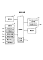
本実施形態は、画像表示装置として腕時計装置に適用した場合を例示したもので、図1は、腕時計装置の基本的な構成要素を示したブロック図である。
腕時計装置は、時刻情報(計時情報)に基づいて複数の指針を運針表示(アナログ時計表示)するもので、制御部1、電源部2、記憶部3、操作部14、ドットマトリックス表示部5などを備えている。制御部1は、電源部(二次電池)2からの電力供給によって動作し、記憶部3内の各種のプログラムに応じてこの腕時計装置の全体動作を制御するもので、この制御部1には図示しないCPU(中央演算処理装置)やメモリなどの他に、計時情報(年月日、時分秒)を逐次計時する計時回路1aが設けられている。
Hereinafter, an embodiment of the present invention will be described with reference to FIGS.
The present embodiment exemplifies a case where the present invention is applied to a wristwatch device as an image display device, and FIG. 1 is a block diagram showing basic components of the wristwatch device.
The wristwatch device displays the movement of a plurality of hands (analog clock display) based on time information (timekeeping information). The
記憶部3は、例えば、ROM、フラッシュメモリなどを有する構成で、本実施形態を実現するためのプログラムや各種のアプリケーションが格納されているプログラムメモリ3aの他に、アナログ時計表示用として各背景画像メモリ3b、各指針画像メモリ3c、各指針情報メモリ3d、現デザインメモリ3e、運針領域メモリ3fが設けられている。各背景画像メモリ3bは、複数の指針を運針表示する場合に、文字盤など背景となる各種のデザインの背景画像をライブラリーとして複数種記憶するメモリである。各指針画像メモリ3cは、複数の指針(時針、分針、秒針)に対応してデザインの異なる各種の指針画像をライブラリーとして複数種記憶するメモリである。各指針情報メモリ3dは、各指針の運針を制御する情報として、例えば、時針であれば、その指針を24時間に1回転すべきことを示す情報、分針であれば、その指針を60分に1回転すべきことを示す情報、秒針であれば、その指針を60秒に1回転すべきことを示す情報などを記憶するメモリである。
The
現デザインメモリ3eは、アナログ時計表示用として表示対象となっている現在のデザインの画像(各指針画像及び背景画像)を記憶するメモリであり、新たなデザインのアナログ時計表示の画像が生成されると、その新たなデザインの画像が上書きされて現在のデザインの画像が更新される。すなわち、各背景画像メモリ3b及び各指針画像メモリ3cの中からユーザ操作によって任意に選択された各指針画像及び背景画像によって新たなデザインのアナログ時計の画像が生成されると、その新たに生成されたデザインのアナログ時計の画像(各指針画像及び背景画像)が、現デザインメモリ3eに上書き記憶される。運針領域メモリ3fは、アナログ時計表示用として現デザインメモリ3eに記憶されている複数の指針のうち、最も長い指針(秒針)が1回転する表示軌跡(回転軌跡)を運針領域として特定し、この運針領域を示す情報と共に、この運針領域に関する各種の情報(走査方向など)を記憶するメモリである。
The
操作部4は、電源スイッチの他に、アナログ時計表示モードとデジタル時計表示モードとに切り替える時計モード切り替えスイッチなど、基本的な操作キー(ハードウェアキー)を備えている。ドットマトリックス表示部5は、ドットマトリックス型の液晶ディスプレイで、複数の信号線及び複数の走査線の各交差部に画素がマトリクス状に配置された表示画面を備え、この表示画面の各画素に対応付けられているアドレスを持った画像メモリ5aを有し、各画素が水平同期信号及び垂直同期信号によってスキャンされることによって1フレーム(1画面分)分の画像が表示される。そして、本実施形態では、四角形の表示画面の四隅のいずれかを走査開始点とし、この走査開始点と対角線上の隅を走査終了点として、左から右方向、又は右から左方向への水平走査と、上から下方向、又は下から上方向への垂直走査を行うことが可能となっている。また、この四角形の表示画面上の位置(画素)は、水平走査方向をX軸とし、垂直走査方向をY軸とする平面座標系において、例えば、左上隅を原点とするXY座標値で示される。
The
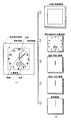
図2は、アナログ時計表示の一例を示すと共に、その時計表示の要素となる各種の画像を示した図である。
図2(1)は、アナログ時計表示の一例を示し、ドットマトリックス表示部5に複数の指針として、時針、分針、秒針をアナログ表示した場合である。すなわち、ドットマトリックス表示部5の画面全体、又はその一部の領域を時計表示領域とした場合に、本実施形態は、この時計表示領域内においてその複数の指針の中で最も長い指針(秒針)の回転軸を中心としてその指針を1回転させた場合の秒針軌跡(円形の回転軌跡)を求め、この円形の秒針軌跡に外接する正方形の仮想枠を運針領域として特定して、この運針領域の情報(例えば、左上座標及び右上座標)を運針領域メモリ3fに記憶するようにしている。更に、この運針領域に基づいてその外側全体を外側背景の領域として特定して、所定の背景(図示省略)を静止画像として固定的に表示するようにしている。なお、外側背景としては、例えば、模様付の背景色などであるが、ユーザ操作によって任意に変更したり、所定期間(例えば、季節)毎に変更したりするようにしてもよい。
FIG. 2 is a diagram showing an example of the analog clock display and various images as elements of the clock display.
FIG. 2 (1) shows an example of an analog clock display, and is a case where the dot
このように本実施形態においては、ドットマトリックス表示部5にアナログ表示を行う場合の表示動作を効率良く行うために、その時計表示領域の全体を2つの領域(運針領域と外側背景の領域)に分けることによって、この運針領域と外側の背景領域に対して処理負荷(例えば、処理量又は処理時間:以下同様)が異なる軽重の表示動作、つまり、運針領域に対しては時刻情報に応じて刻々変化する複数の指針画像の表示位置を運針タイミング毎に制御する比較的に重い表示動作(処理時間の長い表示動作)を行い、外側の背景領域に対しては運針タイミングよりも時間間隔の長いタイミング(本実施形態においてはアナログ時計モードに切り替えたタイミング)で背景画像の表示動作を行う比較的に軽い表示動作(処理時間の短い表示動作)を行うようにしている。
As described above, in the present embodiment, in order to efficiently perform the display operation when the analog display is performed on the dot
図2(2)は、図2(1)で示したアナログ時計表示の要素となる各種の画像を示したもので、この各種の画像として、上述の運針領域の外側の領域内に表示される外側の背景画像と、運針領域内に表示される背景画像、時針画像、分針画像、秒針画像を示している。上述の各背景画像メモリ3bは、運針領域の外側の領域内に表示される外側の背景画像を複数記憶する他に、図2(2)で示した文字盤の背景画像など、デザインの異なる各種の背景画像を複数記憶するもので、その背景画像群の中からユーザ操作によって任意に選択された画像が運針領域の内外に表示される背景となる。この内外の背景画像は、固定的に表示される静止画像、又は、例えば、分針や時針の運針に連動して、花の蕾が徐々に開花するなど、所定の指針の運針タイミングに応答して徐々に変化する画像などである。すなわち、本実施形態においては、上述したように外側の背景画像を静止画像としたが、動画像であってもよく、更に、運針領域内に表示される背景画像も静止画像に限らず、分針や時針に連動して変化する動画像であってもよい。 FIG. 2B shows various images that are elements of the analog clock display shown in FIG. 2A, and these various images are displayed in the area outside the above-mentioned hand movement area. The background image on the outside and the background image, the hour hand image, the minute hand image, and the second hand image displayed in the hand movement area are shown. Each of the background image memories 3b described above stores a plurality of outer background images displayed in a region outside the hand movement region, and also has various different designs such as the background image of the dial shown in FIG. 2 (2). A plurality of background images are stored, and an image arbitrarily selected from the background image group by a user operation is a background displayed inside and outside the hand movement area. This background image inside and outside is a static image that is fixedly displayed, or, for example, in conjunction with the movement of the minute and hour hands, the buds of the flower gradually bloom, and in response to the timing of the movement of a predetermined pointer. For example, an image that changes gradually. That is, in the present embodiment, the outer background image is a still image as described above, but it may be a moving image, and the background image displayed in the hand movement area is not limited to a still image. It may be a moving image that changes in association with the hour hand.
各指針画像メモリ3cは、図2(2)で示した各指針画像の他に、デザインが異なる各種の指針画像を記憶するもので、その指針画像群の中からユーザ操作によって任意に選択された画像が運針領域内に表示される指針となる。このように本実施形態においては、ユーザ操作によって任意に選択されたデザインの背景画像、時針画像、分針画像、秒針画像を組み合わせることによって新たなデザインのアナログ時計画像を生成して表示可能としている。なお、ユーザ操作に限らず、季節などの変化を検出し、その検出タイミングで背景画像、時針画像、分針画像、秒針画像を自動的に組み合わせて新たなデザインのアナログ時計画像を生成するようにしてもよい。
Each
図3は、運針領域を構成する各画素をスキャンしながらアナログ時計を表示する場合の動作概要を説明するための図である。
ドットマトリックス表示部5は、制御部1の制御下で運針領域を構成する各画素を水平同期信号及び垂直同期信号にしたがって所定の方向、つまり、水平走査方向(X軸方向)垂直走査方向(Y軸方向)に順次スキャンする際に、運針タイミング毎にスキャンする位置(画素)は、複数の指針のいずれかを表示する位置(画素)であるか、背景を表示する位置(画素)であるかを判別する動作を行いながらスキャンするようにしている。この場合、秒針を表示する位置であるか、分針を表示する位置であるか、時針を表示する位置であるか、背景を表示する位置であるかをその順次にしたがって順次判別し、その判別結果に基づいてスキャン位置に該当する種類の画像(秒針画像、分針画像、時針画像、背景画像)を表示させる表示動作を行うようにしている。
FIG. 3 is a diagram for explaining an outline of operation when an analog clock is displayed while scanning each pixel forming the hand movement area.
Under the control of the
このような運針領域内の表示動作を効率良く行うために本実施形態は、時刻情報に応じて刻々変化する複数の指針の表示位置が、運針領域を概念的(仮想的)に区分した複数の区分領域のうち、そのいずれかの区分領域内に全て収まっている(偏っている)場合に、その収まっている区分領域を指針有り領域として特定すると共に、この指針有り領域を除く他の全ての区分領域を指針無し領域として特定し、この指針有り領域と指針無し領域に対して、処理負荷が異なる軽重の表示動作を行うように制御するようにしている。すなわち、運針領域の全体を上下方向に上側領域と下側領域に概念的に区分したものとすると、図3(1)は、全ての指針の表示位置が上側領域内に収まっている(偏っている)場合(ケースAの場合)を示している。なお、上側領域と下側領域とを区分する線(仮想線)は、指針の形状及び太さを考慮して、運針領域の全体を上下方向に二等分する線よりも、若干(例えば、指針の太さの1/2+数ドット程度のドット幅)だけ下側に設定されたもので、その大きさは上側領域>下側領域の関係にある。 In order to efficiently perform such a display operation within the hand movement area, in the present embodiment, the display positions of the plurality of hands that change momentarily according to the time information are displayed in a plurality of conceptually (virtually) divided hand movement areas. When all of the divided areas are contained (biased) in any of the divided areas, the divided divided area is specified as the area with the pointer, and all other areas except the area with the pointer are specified. The segmented area is specified as the pointer-free area, and control is performed so that the display area with the pointer and the pointer-free area are displayed with light and heavy loads having different processing loads. That is, assuming that the entire hand movement area is conceptually divided into an upper area and a lower area in the vertical direction, in FIG. 3A, the display positions of all the hands are within the upper area (biased). Case) (case A). Note that the line (virtual line) that separates the upper side region and the lower side region is slightly smaller than the line that bisects the entire hand movement region in the up-down direction in consideration of the shape and thickness of the pointer (for example, The thickness is set to the lower side by [1/2 of the thickness of the pointer + a dot width of several dots], and the size thereof has a relation of the upper side region> the lower side region.
図3(2)は、図3(1)に示すように運針領域の全体が上側領域と下側領域に概念的に区分されている状態において、この上側領域を指針有り領域とし、下側領域を指針無し領域とした場合である。すなわち、上側領域は、指針及び背景が重ね合わせて表示される領域であるため、その上側領域を指針有り領域とし、また、下側領域にはいずれの指針も表示されずに背景のみが表示される領域であるため、その下側領域を指針無し領域とした場合であり、この指針有り領域と指針無し領域とは時刻情報に基づいて刻々と変化する関係にある(以下、同様)。なお、上述したように上側領域>下側領域、つまり、指針有り領域>指針無し領域となっていので、指針有り領域と指針無し領域との境界線上で指針が不表示となることを防ぐことができる(以下、同様)。 As shown in FIG. 3 (1), FIG. 3 (2) shows a state in which the entire hand movement region is conceptually divided into an upper region and a lower region, and the upper region is defined as a region with a pointer, and the lower region. Is a region without a pointer. In other words, since the upper area is an area in which the pointer and the background are displayed in an overlapping manner, the upper area is the area with the pointer, and no pointer is displayed in the lower area and only the background is displayed. This is a case where the area below the pointer is the area without the pointer, and the area with the pointer and the area without the pointer have a relationship that changes momentarily based on time information (the same applies hereinafter). As described above, since the upper area> the lower area, that is, the area with the pointer> the area without the pointer, it is possible to prevent the pointer from not being displayed on the boundary line between the area with the pointer and the area without the pointer. Yes (the same applies below).
そして、この指針有り領域と指針無し領域に対しては処理負荷の異なる軽重の表示動作が行われる。つまり、指針有り領域に対しては運針タイミング毎に複数の指針のいずれかを表示する位置(画素)であるか、背景を表示する位置(画素)であるかを判別すると共に、その判別結果に基づいてその位置に該当する種類の画像を表示する比較的に重い表示動作(処理時間の長い表示動作)を行うが、指針無し領域に対しては運針タイミング毎の判別動作を省略して背景画像を表示する比較的に軽い表示動作(処理時間の短い表示動作)を行うようにしている。 Then, light and heavy display operations with different processing loads are performed on the area with the pointer and the area without the pointer. In other words, it is determined whether the area with the pointer is the position (pixel) for displaying any of the plurality of pointers or the position (pixel) for displaying the background for each hand movement timing. A relatively heavy display operation (a display operation with a long processing time) for displaying an image of a type corresponding to the position is performed based on the background image by omitting the determination operation for each hand movement timing for the pointer-less area. Is displayed relatively lightly (display operation with short processing time).
この場合、運針領域の全体をスキャンする際に、まず、指針有り領域のスキャンを行った後、指針無し領域のスキャンを行うために、運針領域の左上隅を走査開始位置とすると共に、右下隅を走査終了位置とし、また、運針領域の水平走査方向を右方向とし、垂直走査方向を下方向とする。更に、指針有り領域の終了位置を指針無し領域への切り替え位置として検出する。そして、この走査開始位置、走査終了位置、水平走査方向、垂直走査方向、領域切り替え位置(指針有り領域の終了位置)は、運針領域に関する情報として運針領域メモリ3fに一時記憶される。
In this case, when scanning the entire hand movement area, first scan the area with the pointer and then scan the area without the pointer to set the upper left corner of the hand movement area as the scan start position and the lower right corner. Is the scanning end position, the horizontal scanning direction of the hand movement area is the right direction, and the vertical scanning direction is the downward direction. Further, the end position of the area with the pointer is detected as the switching position to the area without the pointer. Then, the scanning start position, the scanning end position, the horizontal scanning direction, the vertical scanning direction, and the area switching position (the ending position of the area with the pointer) are temporarily stored in the hand
図3(3)は、運針領域の全体を上下方向に上側領域と下側領域に概念的に区分したものとすると、全ての指針の表示位置が下側領域内に収まっている(偏っている)場合(ケースBの場合)を示している。この場合においても、上側領域と下側領域とを区分する線(仮想線)は、指針の形状及び太さを考慮して運針領域を上下方向に二等分する線よりも若干上側に設定されたもので、その大きさは上側領域<下側領域の関係にある。図3(4)は、下側領域を指針有り領域とし、上側領域を指針無し領域とした場合で、この指針有り領域と指針無し領域に対しては、上述した場合と同様に、処理負担の異なる軽重の表示動作が行われる。 In FIG. 3 (3), assuming that the entire hand movement area is conceptually divided into an upper area and a lower area in the vertical direction, the display positions of all the hands are within the lower area (deviation). ) Shows the case (case B). Also in this case, the line (virtual line) that separates the upper region and the lower region is set slightly above the line that bisects the hand movement region in the vertical direction in consideration of the shape and thickness of the pointer. The size is such that the upper region <the lower region. FIG. 3 (4) shows a case where the lower area is the area with the pointer and the upper area is the area without the pointer. The area with the pointer and the area without the pointer have the same processing load as in the case described above. Different light and heavy display operations are performed.
この場合、指針有り領域のスキャンを行った後、指針無し領域のスキャンを行うために、運針領域の右下隅を走査開始位置とすると共に、左上隅を走査終了位置とし、また、運針領域の水平走査方向を左方向とし、垂直走査方向を上方向とし、更に、指針有り領域の終了位置を指針無し領域への切り替え位置として検出する。そして、この走査開始位置、走査終了位置、水平走査方向、垂直走査方向、領域切り替え位置は、運針領域に関する情報として運針領域メモリ3fに一時記憶される。
In this case, after scanning the area with the pointer, in order to scan the area without the pointer, the lower right corner of the hand movement area is set as the scanning start position, the upper left corner is set as the scanning end position, and the horizontal movement of the hand movement area is performed. The scanning direction is the left direction, the vertical scanning direction is the upward direction, and the end position of the area with the pointer is detected as the switching position to the area without the pointer. Then, the scanning start position, the scanning end position, the horizontal scanning direction, the vertical scanning direction, and the region switching position are temporarily stored in the hand
図4は、運針領域を構成する各画素をスキャンしながらアナログ時計を表示する場合の動作概要を説明するための図で、運針領域の全体を左右方向に右側領域と左側領域に概念的に区分したものとすると、図4(1)は、全ての指針の表示位置が右側領域内に収まっている(偏っている)場合(ケースCの場合)を示している。この場合においても、右側領域と左側領域とを区分する線(仮想線)は、指針の形状及び太さを考慮して運針領域を左右方向に二等分する線よりも若干左側に設定されたもので、その大きさは右側領域>左側領域の関係にある。 FIG. 4 is a diagram for explaining an outline of operation when an analog clock is displayed while scanning each pixel forming the hand movement area. The whole hand movement area is conceptually divided into a right side area and a left side area in the left-right direction. If so, FIG. 4 (1) shows a case (case C) in which the display positions of all the hands are within (biased) within the right region. Also in this case, the line that divides the right side region and the left side region (virtual line) is set slightly to the left of the line that bisects the hand movement region in the left-right direction in consideration of the shape and thickness of the pointer. The size is such that the right side region> the left side region.
図4(2)は、右側領域を指針有り領域とし、左側領域を指針無し領域とした場合で、この指針有り領域と指針無し領域に対しては、上述した場合と同様に、処理負担の異なる軽重の表示動作が行われる。この場合、指針有り領域のスキャンを行った後、指針無し領域のスキャンを行うために、運針領域の右上隅を走査開始位置とすると共に、左下隅を走査終了位置とし、また、運針領域の水平走査方向を左方向とし、垂直走査方向を下方向とし、更に、指針有り領域の終了位置を指針無し領域への切り替え位置として検出する。そして、この走査開始位置、走査終了位置、水平走査方向、垂直走査方向、領域切り替え位置は、運針領域に関する情報として運針領域メモリ3fに一時記憶される。
FIG. 4B shows a case where the right side area is the area with the pointer and the left side area is the area without the pointer. Similar to the above case, the processing load is different between the area with the pointer and the area without the pointer. Light and heavy display operations are performed. In this case, after scanning the area with the pointer, in order to scan the area without the pointer, the upper right corner of the hand movement area is set as the scanning start position, the lower left corner is set as the scanning end position, and the horizontal movement of the hand movement area is performed. The scanning direction is the left direction, the vertical scanning direction is the downward direction, and the end position of the area with the pointer is detected as the switching position to the area without the pointer. Then, the scanning start position, the scanning end position, the horizontal scanning direction, the vertical scanning direction, and the region switching position are temporarily stored in the hand
図4(3)は、全ての指針の表示位置が左側領域内に収まっている(偏っている)場合(ケースDの場合)を示している。この場合においても、右側領域と左側領域とを区分する線(仮想線)は、指針の形状及び太さを考慮して運針領域を左右方向に二等分する線よりも若干右側に設定されたもので、その大きさは右側領域<左側領域の関係にある。図4(4)は、この左側領域を指針有り領域とし、右側領域を指針無し領域とした場合を示し、上述した場合と同様に、この指針有り領域と指針無し領域に対しては、処理負荷の異なる軽重の表示動作が行われる。 FIG. 4C shows the case where the display positions of all the hands are within (biased) within the left side area (case D). Also in this case, the line (virtual line) that separates the right side region and the left side region is set slightly to the right of the line that bisects the hand movement region in the left-right direction in consideration of the shape and thickness of the pointer. The size is such that the right side region <the left side region. FIG. 4 (4) shows the case where the left side area is the area with the pointer and the right side area is the area without the pointer. As in the case described above, the processing load is applied to the area with the pointer and the area without the pointer. Different light and heavy display operations are performed.
この場合、指針有り領域のスキャンを行った後、指針無し領域のスキャンを行うために、運針領域の左下隅を走査開始位置とすると共に、右上隅を走査終了位置とし、また、運針領域の水平走査方向を右方向とし、垂直走査方向を上方向とし、更に、指針有り領域の終了位置を指針無し領域への切り替え位置として検出する。そして、この走査開始位置、走査終了位置、水平走査方向、垂直走査方向、領域切り替え位置は、運針領域に関する情報として運針領域メモリ3fに一時記憶される。
In this case, after scanning the area with the pointer, in order to scan the area without the pointer, the lower left corner of the hand movement area is the scanning start position, the upper right corner is the scanning end position, and the horizontal movement of the hand movement area is performed. The scanning direction is the right direction, the vertical scanning direction is the upward direction, and the end position of the area with the pointer is detected as the switching position to the area without the pointer. Then, the scanning start position, the scanning end position, the horizontal scanning direction, the vertical scanning direction, and the region switching position are temporarily stored in the hand
このように本実施形態において制御部1は、ドットマトリックス表示部5の時計表示領域に対して、時刻情報を基に複数の指針画像の運針表示を行う他に、背景画像の表示を行う場合に、複数の指針画像が表示される領域(運針領域、又は運針領域内の指針有り領域)を特定し、この特定した領域と、この領域を除く他の領域(運針領域の外側領域、又は運針領域内の指針無し領域)に対して、処理負荷が異なる軽重の表示動作を行うように制御するようにしている。
As described above, in the present embodiment, the
すなわち、本実施形態においては、時計表示領域の全体を2つの領域として、指針画像の表示位置が含まれる第一の領域(運針領域)を特定すると共に、この第一の領域を除く表示領域において、指針画像の表示位置を含まず、且つ少なくとも一部に背景画像が表示される第二の領域(外側背景の領域)を特定する、更に、運針領域内においても、指針画像の表示位置が含まれる第一の領域(指針有り領域)を特定すると共に、この第一の領域を除く表示領域において、指針画像の表示位置を含まず、且つ少なくとも一部に背景画像が表示される第二の領域(指針無し領域)を特定する。そして、この第一の領域(運針領域、又は運針領域内の指針有り領域)と、第二の領域(運針領域の外側領域、又は運針領域内の指針無し領域)に対して、処理負荷が異なる軽重の表示動作を行うようにしている。 That is, in the present embodiment, the entire timepiece display area is defined as two areas, the first area (hand movement area) including the display position of the pointer image is specified, and the display area excluding the first area is specified. The display position of the pointer image is not included, and the second area (outer background area) in which the background image is displayed is specified in at least a part, and the display position of the pointer image is also included in the hand movement area. The second area in which the background image is displayed in at least part of the display area excluding the first area Specify the (no pointer area). Then, the processing load is different between the first area (the hand movement area or the area with the pointer in the hand movement area) and the second area (the area outside the hand movement area or the area without the pointer in the hand movement area). The display operation is light and heavy.
次に、本実施形態における腕時計装置の動作概念を図5〜図7に示すフローチャートを参照して説明する。ここで、これらのフローチャートに記述されている各機能は、読み取り可能なプログラムコードの形態で格納されており、このプログラムコードにしたがった動作が逐次実行される。また、ネットワークなどの伝送媒体を介して伝送されてきた上述のプログラムコードに従った動作を逐次実行することもできる。すなわち、記録媒体の他に、伝送媒体を介して外部供給されたプログラム/データを利用して本実施形態特有の動作を実行することもできる。なお、図5及び図6は、腕時計装置の全体動作のうち、本実施形態の特徴部分の動作概要を示したフローチャートであり、この図5及び図6のフローから抜けた際には、全体動作のメインフロー(図示省略)に戻る。 Next, the operation concept of the wristwatch device according to the present embodiment will be described with reference to the flowcharts shown in FIGS. Here, each function described in these flowcharts is stored in the form of a readable program code, and the operation according to this program code is sequentially executed. Further, the operation according to the above-mentioned program code transmitted via a transmission medium such as a network can be sequentially executed. That is, in addition to the recording medium, the program / data externally supplied via the transmission medium may be used to execute the operation peculiar to the present embodiment. 5 and 6 are flowcharts showing an outline of the operation of the characteristic part of the present embodiment in the overall operation of the wristwatch device. When the flow of FIGS. 5 and 6 is exited, the overall operation is performed. Return to the main flow (not shown).
図5及び図6は、アナログ時計表示モードに切り替えられた際に実行開始される動作を示したフローチャートである。
まず、制御部1は、アナログ時計表示モードに切り替えられると、アナログ時計表示のデザイン変更が指示されたかを調べる(図5のステップA1)。このデザイン変更は、指針画像や背景画像の形状、模様、色などの変更を指示するもので、ユーザ操作によって指示される場合に限らず、例えば、季節の変わり目などを検出し、そのタイミングで指示される場合であってもよい。
5 and 6 are flowcharts showing the operation that is started when the mode is switched to the analog clock display mode.
First, when the
ここで、アナログ時計表示のデザイン変更が指示されなければ(ステップA1でNO)、後述するステップA4に移るが、そのデザイン変更が指示されたときには(ステップA1でYES)、その変更指示に応じて新たな時計デザインの画像を生成する処理を行う(ステップA2)。すなわち、制御部1は、アナログ時計表示用の各背景画像メモリ3b、各指針画像メモリ3cの中からユーザ操作によって選択的に読み出されたデザインの背景画像、時針画像、分針画像、秒針画像を組み合わせて新たな時計デザインの画像を生成し、現デザインメモリ3eに上書きすることによりその内容を書き替える。
If the design change of the analog clock display is not instructed (NO in step A1), the process proceeds to step A4, which will be described later, but when the design change is instructed (YES in step A1), the change instruction is issued. Processing for generating an image of a new watch design is performed (step A2). That is, the
このようにして新たな時計デザインの画像が生成されると、その複数の指針の中で最も長い指針(例えば、秒針)の回転軸を中心としてその指針を1回転させた場合の秒針軌跡(円形の回転軌跡)を求め、この円形の秒針軌跡に外接する正方形の仮想枠を運針領域として特定して、この運針領域を示す情報(例えば、左上座標及び右上座標)を運針領域メモリ3fに上書きする(ステップA3)。その後、次のステップA4に移る。なお、指針を1回転させて描画した回転軌跡から運針領域を特定する場合に限らず、最も長い指針の回転軸を中心とする円の半径を求め、その半径から運針領域を算出して特定するようにしてもよく、運針領域の特定の仕方は任意である。
When an image of a new timepiece design is generated in this way, the second hand locus (circular shape) when the hand is rotated once around the rotation axis of the longest hand (for example, the second hand) among the plurality of hands. Rotation locus), a virtual square frame circumscribing the circular second hand locus is specified as a hand movement area, and information indicating the hand movement area (for example, upper left coordinate and upper right coordinate) is overwritten in the hand
上述のステップA4は、運針領域メモリ3fから運針領域を読み出すもので、デザインの変更が指示されなければ(ステップA1でNO)、既存の時計デザインの画像に対応して記憶されている運針領域が読み出されるが、時計デザインの変更が指示された場合には(ステップA1でYES)、新たな時計デザインに対応して記憶されている運針領域が読み出される。次に、ドットマトリックス表示部5の時計表示領域において、読み出した運針領域に基づいてその運針領域の外側全体を外側背景の領域として特定し(ステップA5)、この外側背景の領域の全体に所定の背景画像を表示する動作を行う(ステップA6)。なお、本実施形態において、この外側背景の画像は、刻々と変化する動画像ではなく、固定的に表示される静止画像であるため、運針領域内に動画像を表示する動作と、外側背景を表示する動作とを分けて行うようにしている。
The above-mentioned step A4 is to read the hand movement area from the hand
次に、ステップA7に移り、時刻更新(運針)タイミング(例えば、1秒間隔)であるかを調べ、運針タイミングでなければ(ステップA7でNO)、その他の処理として、ユーザ操作を受け付けてユーザ指示に応じた処理(例えば、時刻合わせ処理など)を行うが(ステップA8)、運針タイミングであれば(ステップA7でYES)、計時回路1aから現在の時刻情報(計時情報)を取得し(ステップA9)、この現在の時刻情報から時針、分針、秒針の表示位置を求める(ステップA10)。例えば、運針領域の左上隅を原点とする平面座標系において、時針、分針、秒針の表示位置として、各指針の基端部、先端部、中間部のいずれかの座標を求める。そして、全ての指針の表示位置が運針領域内の上下方向、又は左右方向のいずれに偏っているかに応じて、運針領域内に指針有り領域と指針無し領域を特定したり、運針領域を走査する方向を特定したりする処理に移る(ステップA11)。 Next, the process proceeds to step A7, and it is checked whether it is the time update (hand movement) timing (for example, 1 second interval). If it is not the hand movement timing (NO in step A7), the user operation is accepted as another process to accept the user operation. Although the process (for example, time adjustment process) according to the instruction is performed (step A8), if it is the hand movement timing (YES in step A7), the current time information (clock information) is acquired from the clock circuit 1a (step). A9), the display positions of the hour hand, the minute hand and the second hand are obtained from the present time information (step A10). For example, in the plane coordinate system having the origin at the upper left corner of the hand movement area, the coordinates of any one of the base end portion, the tip end portion, and the intermediate portion of each pointer are obtained as the display positions of the hour hand, the minute hand, and the second hand. Then, depending on whether the display positions of all the pointers are biased in the vertical direction or the horizontal direction in the hand movement area, the area with the pointer and the area without the pointer are specified in the hand movement area, or the hand movement area is scanned. The process moves to specifying the direction (step A11).
図7は、指針有り領域、指針無し領域、走査方向を特定する処理(図5のステップA11)を詳述するためのフローチャートである。
まず、制御部1は、運針領域の全体を上下方向に上側領域と下側領域に、又は左右方向に右側領域と左側領域に概念的に区分されているものとした場合に、全ての指針の表示位置が上述のケースA〜Dのいずれに該当しているかを調べる。すなわち、全ての指針の表示位置が上側領域内に収まっている(偏っている)か(ステップB1)、下側領域内に収まっているか(ステップB5)、右側領域内に収まっているか(ステップ9)、左側領域内に収まっているかを調べる(ステップB13)。
FIG. 7 is a flow chart for explaining in detail the processing for identifying the area with the pointer, the area without the pointer, and the scanning direction (step A11 in FIG. 5).
First, when the entire hand movement area is conceptually divided into an upper area and a lower area in the vertical direction, or a right area and a left area in the horizontal direction, all of the pointers It is checked which of the cases A to D the display position corresponds to. That is, whether the display positions of all the hands are within the upper area (biased) (step B1), within the lower area (step B5), or within the right area (step 9). ), And it is checked whether it is within the left area (step B13).
いま、時刻情報が、例えば、図3(1)に示すように“11時8分12秒”、又は、“2時10分50秒”であり、全ての指針の表示位置が上側領域内に収まっている場合(ケースAの場合)には(ステップB1でYES)、図3(2)に示すように、その上側領域を指針有り領域として特定すると共に、この領域を除く他の領域(下側領域)を指針無し領域として特定し、更に指針有り領域の終了位置を指針無し領域への切り替え位置として特定して、この指針有り領域、指針無し領域、切り替え位置を運針領域に関する情報として運針領域メモリ3fに一時記憶させる処理を行う(ステップB2)。そして、運針領域の右上隅を走査開始位置、左下隅を走査終了位置として特定(ステップB3)すると共に、運針領域の水平走査方向を左方向とし、垂直走査方向を下方向とし特定して、この走査開始位置、走査終了位置、水平走査方向、垂直走査方向を運針領域に関する情報として運針領域メモリ3fに一時記憶させる処理を行う(ステップB4)。
Now, the time information is, for example, “11:08:12” or “2:10:50” as shown in FIG. 3A, and the display positions of all the hands are within the upper area. If it is within the range (case A) (YES in step B1), as shown in FIG. 3 (2), the upper area is specified as the area with the pointer, and other areas (lower area) are excluded. Side area) is specified as a pointer-free area, and the end position of the pointer-containing area is specified as a switching position to the pointer-free area. Processing for temporarily storing in the
また、時刻情報が、例えば、図3(3)に示すように“8時24分17秒”、又は、“4時40分30秒”であり、全ての指針の表示位置が下側領域内に収まっている場合(ケースBの場合)には(ステップB5でYES)、図3(4)に示すようにその下側領域を指針有り領域として特定すると共に、この領域を除く他の領域(上側領域)を指針無し領域として特定し、更に指針有り領域の終了位置を指針無し領域への切り替え位置として特定し、この指針有り領域、指針無し領域、切れ替え位置を運針領域に関する情報として運針領域メモリ3fに一時記憶させる処理を行う(ステップB6)。そして、運針領域の右下隅を走査開始位置、左上隅を走査終了位置として特定し(ステップB7)、更に、運針領域の水平走査方向を左方向とし、垂直走査方向を上方向とし特定して、この走査開始位置、走査終了位置、水平走査方向、垂直走査方向を運針領域に関する情報として運針領域メモリ3fに一時記憶させる処理を行う(ステップB8)。
Further, the time information is, for example, “8:24:17” or “4:40:30” as shown in FIG. 3C, and the display positions of all the hands are within the lower region. If it is within the range (case B) (YES in step B5), as shown in FIG. 3 (4), the lower area is specified as a pointer area, and other areas except this area ( The upper area) is specified as the pointer-free area, and the end position of the pointer-containing area is specified as the switching position to the pointer-free area. A process of temporarily storing in the
また、時刻情報が、例えば、図4(1)に示すように“12時8分23秒”、又は、“5時25分15秒”であり、全ての指針の表示位置が右側領域内に収まっている場合(ケースCの場合)には(ステップB9でYES)、図4(2)に示すようにその右側領域を指針有り領域として特定すると共に、この領域を除く他の領域(左側領域)を指針無し領域として特定し、更に指針有り領域の終了位置を指針無し領域への切り替え位置として特定して、この指針有り領域、指針無し領域、切り替え位置を運針領域に関する情報として運針領域メモリ3fに一時記憶させる処理を行う(ステップB10)。そして、運針領域の右上隅を走査開始位置、左下隅を走査終了位置として特定し(ステップB11)、更に、運針領域の水平走査方向を左方向とし、垂直走査方向を下方向とし特定して、この走査開始位置、走査終了位置、水平走査方向、垂直走査方向を運針領域に関する情報として運針領域メモリ3fに一時記憶させる処理を行う(ステップB12)。
Further, the time information is, for example, “12: 8: 23” or “5:25:15” as shown in FIG. 4A, and the display positions of all the hands are within the right area. If it is within the range (case C) (YES in step B9), the right side area is specified as the area with the pointer as shown in FIG. 4B, and the other area (left side area) is excluded. ) Is specified as a pointer-free area, and the end position of the pointer-containing area is specified as a switching position to the pointer-free area. Is temporarily stored (step B10). Then, the upper right corner of the hand movement area is specified as the scanning start position and the lower left corner is specified as the scanning end position (step B11). Further, the horizontal scanning direction of the hand movement area is specified as the left direction, and the vertical scanning direction is specified as the downward direction. The scanning start position, the scanning end position, the horizontal scanning direction, and the vertical scanning direction are temporarily stored in the hand
また、時刻情報が、例えば、図4(3)に示すように“8時49分36秒”、又は、“11時45分55秒”であり、全ての指針の表示位置が左側領域内に収まっている場合(ケースDの場合)には(ステップB13でYES)、図4(4)に示すようにその左側領域を指針有り領域として特定すると共に、この領域を除く他の領域(右側領域)を指針無し領域として特定し、更に指針有り領域の終了位置を指針無し領域への切り替え位置として特定して、この指針有り領域、指針無し領域、切り替え位置を運針領域に関する情報として運針領域メモリ3fに一時記憶させる処理を行う(ステップB14)。そして、運針領域の左下隅を走査開始位置、右上隅を走査終了位置として特定し(ステップB15)、更に、運針領域の水平走査方向を右方向とし、垂直走査方向を上方向とし特定して、この走査開始位置、走査終了位置、水平走査方向、垂直走査方向を運針領域に関する情報として運針領域メモリ3fに一時記憶させる処理を行う(ステップB16)。
Further, the time information is, for example, “8:49:36” or “11:45:55” as shown in FIG. 4C, and the display positions of all the hands are within the left area. If it is within the range (case D) (YES in step B13), the left side area is specified as the area with the pointer as shown in FIG. 4 (4), and other areas (right side area) are excluded. ) Is specified as a pointer-free area, and the end position of the pointer-containing area is specified as a switching position to the pointer-free area. Is temporarily stored (step B14). Then, the lower left corner of the hand movement area is specified as the scanning start position and the upper right corner is specified as the scanning end position (step B15), and the horizontal scanning direction of the hand movement area is specified as the right direction and the vertical scanning direction is specified as the upward direction. The scanning start position, the scanning end position, the horizontal scanning direction, and the vertical scanning direction are temporarily stored in the hand
一方、時刻情報が、例えば、“12時40分10秒”、又は、“10時25分40秒”であり、運針領域内において全ての指針の表示位置が分散している場合、つまり、上側領域、下側領域、右側領域、左側領域のいずれにも収まらない場合(ケースA〜Dのいずれにも該当しない場合)には(ステップB13でNO)、運針領域の全体を指針有り領域として特定する(ステップB17)。その後、上述のステップB3に移り、運針領域の右上隅を走査開始位置、左下隅を走査終了位置として特定し、更に、運針領域の水平走査方向を左方向とし、垂直走査方向を下方向とし特定して、この走査開始位置、走査終了位置、水平走査方向、垂直走査方向を運針領域に関する情報として運針領域メモリ3fに一時記憶させる処理を行う(ステップB4)。
On the other hand, when the time information is, for example, “12:40:10,” or “10:25:40,” and the display positions of all hands are dispersed in the hand movement area, that is, the upper side. If it does not fit in any of the area, the lower area, the right area, and the left area (if it does not correspond to any of Cases A to D) (NO in step B13), the entire hand movement area is specified as the pointer area. (Step B17). After that, the process moves to step B3, where the upper right corner of the hand movement area is specified as the scanning start position and the lower left corner is specified as the scanning end position, and the horizontal scanning direction of the hand movement area is specified as the left direction and the vertical scanning direction is specified as the downward direction. Then, the scanning start position, the scanning end position, the horizontal scanning direction, and the vertical scanning direction are temporarily stored in the hand
このようにして指針有り領域、指針無し領域、走査方向を特定する処理(図5のステップA11)が終了すると、図6のフローに移り、運針領域メモリ3fに一時記憶させている運針領域に関する情報に基づいて、その走査開始位置、走査終了位置で示される領域内の各画素を水平走査方向、垂直走査方向で示される方向に順次スキャンする動作を開始する(ステップA12)。そして、このスキャン動作中において、現在のスキャン位置(画素)は秒針の表示位置であるか、分針の表示位置であるか、時針の表示位置であるか、背景の表示位置であるかを判別する(ステップA13)。
In this way, when the processing for specifying the pointer area, the pointer-free area, and the scanning direction (step A11 in FIG. 5) is completed, the processing moves to the flow in FIG. 6 and the information regarding the hand movement area temporarily stored in the hand
いま、現在のスキャン位置(画素)が秒針の表示位置であれば(ステップA14でYES)、他の指針の表示位置であるかに拘わらず、その位置に秒針画像を表示させる処理を行うが(ステップA15)、秒針ではなく、分針の表示位置であれば(ステップA16でYES)、その位置に分針画像を表示させる処理を行う(ステップA17)。また、分針ではなく、時針の表示位置であれば(ステップA18でYES)、その位置に時針画像を表示させる処理を行う(ステップA19)。なお、秒針、分針、時針のいずれでもなければ(ステップA18でNO)、その位置に背景画像を表示させる処理を行う(ステップA20)。このようにして1画素分の表示が終ると、ステップA21に移り、現在のスキャン位置(画素)は、領域の切り替え位置(指針有り領域の終了位置)に達したかを調べ、領域の切り替え位置に達していなければ(ステップA21でNO)、上述のステップA12に戻り、以下、上述の表示動作を繰り返す。 If the current scan position (pixel) is the display position of the second hand (YES in step A14), the second hand image is displayed at that position regardless of the display position of another pointer ( If it is the display position of the minute hand instead of the second hand (step A15) (YES in step A16), the process of displaying the minute hand image at that position is performed (step A17). If it is the display position of the hour hand instead of the minute hand (YES in step A18), the process of displaying the hour hand image at that position is performed (step A19). If it is neither the second hand, the minute hand, nor the hour hand (NO in step A18), the process of displaying the background image at that position is performed (step A20). When the display for one pixel is completed in this way, the process proceeds to step A21, and it is checked whether the current scan position (pixel) has reached the area switching position (end position of the area with the pointer), and the area switching position is determined. If it has not reached (NO in step A21), the process returns to step A12, and the above-described display operation is repeated.
ここで、現在のスキャン位置(画素)が切り替え位置に達した場合、つまり、指針有り領域に対する表示動作が完了した場合には(ステップA21でYES)、上述した判別処理(ステップA13、A14、A16、A18)を省略して、背景画像を表示する動作に移る(ステップA22)。そして、現在のスキャン位置(画素)は、走査終了位置に達したかを調べ(ステップA23)、走査終了位置でなければ(ステップA23でNO)、上述のステップA22に戻り、以下、背景画像を表示する動作を繰り返す。 Here, when the current scan position (pixel) reaches the switching position, that is, when the display operation for the pointer area is completed (YES in step A21), the above-described determination processing (steps A13, A14, A16). , A18) is omitted, and the process moves to the operation of displaying the background image (step A22). Then, it is checked whether the current scan position (pixel) has reached the scan end position (step A23). If it is not the scan end position (NO in step A23), the process returns to step A22 described above, and the background image is displayed. Repeat the display operation.
ここで、走査終了位置に達することによって指針無し領域に対する表示動作が完了すると(ステップA23でYES)、アナログ時計表示モードの終了かを調べ(ステップA24)、アナログ時計表示モードのままであれば(ステップA24でNO)、図5のステップA7に戻るが、アナログ時計表示モードが解除されて他の時計表示モードに切り替えられた場合には(ステップA24でYES)、その他の時計表示モード(デジタル時計モード)の処理に移る。 Here, when the display operation for the pointer-free area is completed by reaching the scanning end position (YES in step A23), it is checked whether or not the analog timepiece display mode is ended (step A24). If NO in step A24) and the process returns to step A7 in FIG. 5, but the analog clock display mode is canceled and switched to another clock display mode (YES in step A24), another clock display mode (digital clock) Mode) processing.
以上のように、本実施形態においては、計時回路1aから取得した時刻情報を基に複数の指針画像の運針表示を行う他に、表示部5の表示領域のうち、指針画像の表示位置が含まれる第一の領域を特定すると共に、この第一の領域を除く表示領域において、指針画像の表示位置を含まず、且つ少なくとも一部に背景画像が表示される第二の領域を特定し、この第一の領域と第二の領域に対して、処理負荷が異なる軽重の表示動作を行うように制御するようにしたので、指針画像の運針表示の他に、背景画像を表示したとしてその処理負荷の増大を抑制することが可能となる。
As described above, in the present embodiment, in addition to performing the hand movement display of a plurality of pointer images based on the time information acquired from the timing circuit 1a, the display position of the pointer image is included in the display area of the
本実施形態において制御部1は、時計表示領域のうち、複数の指針の中で最も長い指針の回転軌跡に基づいて複数の指針画像が表示される運針領域として特定すると共に、この運針領域の外側の領域を背景画像が表示される外側の背景領域として特定し、この運針領域と外側の背景領域に対して、処理負荷が異なる軽重の表示動作を行うように制御するようにしたので、運針領域とその外側の領域とに分けて表示動作を制御することができ、全体の表示を効率良く行うことが可能となる。
In the present embodiment, the
制御部1は、複数の指針の中で最も長い指針の回転軌跡に外接する四角形を複数の指針画像が表示される運針領域として特定するようにしたので、運針領域を対角の2点で表すことができ、運針領域のアドレス管理が容易になると共に、運針領域を複数に区分した場合にもその区分領域の管理も容易なものとなる。
Since the
運針領域に対しては、時刻情報に応じて刻々変化する複数の指針画像の表示位置を運針タイミング毎に制御する表示動作を行い、外側の背景領域に対しては、運針タイミングよりも時間間隔の長いタイミングで背景画像の表示動作を行うように制御するようにしたので、外側の背景領域に対して、指針画像を表示する位置あるか、背景画像を表示する位置であるかを判別する動作を省略できる他に、運針領域に比べて、背景画像を更新する間隔を短くすることができる。 For the hand movement area, a display operation is performed to control the display positions of a plurality of pointer images that change in accordance with time information at each hand movement timing, and for the outer background area, the time interval is set to be longer than the hand movement timing. Since the control is performed so that the background image is displayed at a long timing, it is possible to perform the operation of determining whether the position where the pointer image is displayed or the position where the background image is displayed with respect to the outer background area. Besides being omissible, the interval for updating the background image can be shortened as compared with the hand movement area.
時刻情報に応じて刻々変化する複数の指針の表示位置が、運針領域を概念的に区分した複数の区分領域のうち、そのいずれの区分領域内に全て収まる場合に、その収まっている区分領域を指針有り領域として特定すると共に、この指針有り領域を除く他の全ての区分領域を指針無し領域として特定し、この指針有り領域と指針無し領域に対して、処理負荷が異なる軽重の表示動作を行うように制御するようにしたので、運針領域内に背景画像を表示したとしてもその処理時間の増大を抑制することが可能となる。 If the display positions of the pointers that change momentarily according to the time information fall within any of the divided areas that conceptually divide the hand movement area, select the divided area that is within that area. In addition to specifying the area with the pointer, all the other divided areas except the area with the pointer are specified as the area without the pointer, and light and heavy display operations with different processing loads are performed for the area with the pointer and the area without the pointer. Since the control is performed as described above, it is possible to suppress an increase in processing time even if the background image is displayed in the hand movement area.
ドットマトリックス表示部5において、背景画像の表示と指針画像の運針表示を行う際に、運針領域内に特定された指針有り領域に対しては、その領域を構成する各画素を所定方向に走査することにより運針タイミング毎に複数の指針のいずれかを表示する位置であるか、背景を表示する位置であるかを判別する動作を画素毎に順次行いながら背景画像上に複数の指針画像を運針表示させる表示動作を行い、前記運針領域内に特定された指針無し領域に対しては、上述の判別動作を省略して背景画像の表示動作を行うようにしたので、運針領域内に背景画像を表示したとしてもその処理時間の増大を抑制することが可能となる。また、背景画像や各指針画像をレイヤーとして合成する方法やスプライト機能を使って各指針画像を背景上に合成する方法に比べて、特別な画像合成装置や合成処理が不必要となり、処理負荷も軽減することができるため、例えば、ウェアラブル機器のような小型で省電力な電子機器にも利用可能となる。
In the dot
運針タイミング毎に複数の指針のいずれかを表示する位置であるか、背景を表示する位置であるかを判別する動作を行いながら背景画像上に複数の指針画像を運針表示させる際に、複数の指針を構成する時針、分針、秒針が背景の上にその順序で重なり合っているものとして、その判別を行うようにしたので、例えば、最上位の秒針を表示する位置であると判別した場合には、それ以降の判別、つまり、分針か時針か背景かの判別を行わなくてもよく、その判別を効率良く行うことが可能となる。 When displaying a plurality of pointer images on the background image while performing the operation to determine whether it is the position to display any one of the plurality of pointers or the position to display the background for each hand movement timing, Since the hour hand, minute hand, and second hand that compose the hands overlap on the background in that order, the determination is made so that, for example, when it is determined that the top second hand is displayed, The subsequent determination, that is, the determination of the minute hand, the hour hand, or the background need not be performed, and the determination can be efficiently performed.
運針領域を概念的に区分した複数の区分領域のうち、時刻情報に応じて刻々変化する複数の指針の表示位置が、いずれの区分領域内に全て収まる場合に、その収まっている区分領域(指針有り領域)が運針領域内のどこに存在しているかに応じて、その区分領域への走査方向を変更するようにしたので、複数の指針の表示位置の全てが収まっている指針有り領域をスキャンしてから指針無し領域をスキャンすることができる。 When the display positions of a plurality of pointers that change momentarily according to time information are all within the divided area that conceptually divides the hand movement area, the divided area (guideline) The scanning direction to the segmented area is changed according to where in the hand movement area (the area with the pointer). Then, the pointerless area can be scanned.
運針領域内を概念的に区分した複数の区分領域は、その運針領域を上下方向に区分した上側領域と下側領域、又は左右方向に区分した右側領域と左側領域であるので、運針領域の全体を略二等分した領域を指針有り領域、指針無し領域とすることができ、運針領域の全体を複数の領域に区分する場合にその区分が容易なものとなる。 The plurality of divided areas conceptually dividing the hand movement area are the upper area and the lower area obtained by dividing the hand movement area in the vertical direction, or the right area and the left area obtained by dividing the hand operation area in the left-right direction. The area roughly divided into two can be made into the area with the pointer and the area without the pointer, and when the entire hand movement area is divided into a plurality of areas, the division is easy.
運針領域を上下方向に区分した上側領域と下側領域、又は左右方向に区分した右側領域と左側領域のうち、時刻情報に応じて刻々変化する複数の指針の表示位置が全て収まっている領域が、上側領域であれば、水平走査方向を右方向、垂直走査方向を下方向とし、下側領域であれば、水平走査方向を左方向、垂直走査方向を上方向とし、右側領域であれば、水平走査方向を左方向、垂直走査方向を下方向とし、左側領域であれば、水平走査方向を右方向、垂直走査方向を上方向に変更するようにしたので、複数の指針の表示位置が全て収まっている領域を素早くスキャンすることができる。 Of the upper and lower areas that divide the hand movement area in the vertical direction, or the right area and the left area that are divided in the left and right direction, the area where all the display positions of a plurality of pointers that change momentarily according to time information are settled. If the upper region, the horizontal scanning direction is the right direction, the vertical scanning direction is the downward direction, if the lower region, the horizontal scanning direction is the left direction, the vertical scanning direction is the upward direction, if the right region, The horizontal scanning direction is left, the vertical scanning direction is downward, and if it is the left area, the horizontal scanning direction is changed to the right direction and the vertical scanning direction is changed to the upward direction. You can quickly scan the contained area.
運針領域を概念的に区分した複数の区分領域は、複数の指針の形状、太さをも参照して決定された領域であるので、運針領域の全体を等分するのではなく、指針の形状、太さを考慮して大きさを変えて区分することができ、運針領域の全体を複数の領域に区分しても指針や背景を正確に表示することができる。 Since the plurality of divided areas conceptually dividing the hand movement area are areas that are determined by also referring to the shapes and thicknesses of the plurality of hands, the shape of the hands is not divided evenly into the entire hand movement area. , The size can be changed in consideration of the thickness, and even if the entire hand movement region is divided into a plurality of regions, the pointer and the background can be accurately displayed.
デザインの異なる各種の指針画像及び背景画像の中から選択された画像に基づいて新たなデザインのアナログ時計表示用の画像が生成された場合には、この生成された画像に基づいて、複数の指針画像を運針表示すると共に、背景画像を表示するようにしたので、アナログ時計表示のデザインが変更された場合にも同様に対応することができると共に、合成用の書き換えメモリを使用しなくても、ドットマトリックス表示部5の画像メモリ5aに描画するだけで背景画像上に複数の指針画像を運針表示させることができる。
When an image for analog clock display of a new design is generated based on an image selected from various pointer images of different designs and a background image, a plurality of pointers are generated based on the generated image. Since the background image is displayed together with the hand movement display of the image, it is possible to deal with the case where the design of the analog clock display is changed in the same manner, and without using a rewriting memory for composition. By simply drawing in the
上述の構成により、本実施形態は、スプライト画像表示のような画像処理用のハードウェアとCPUを組み合わせる表示装置や、演算能力の高いCPUを持たない表示装置においても好適に時計表示処理を行うことが出来る。また、上記の構成を具備する表示装置に本実施形態を適用する場合でも、時計表示処理に係る処理負荷を軽減することが可能である。 With the above-described configuration, the present embodiment preferably performs the clock display processing even in a display device that combines a CPU for image processing hardware such as sprite image display and a CPU, or a display device that does not have a CPU with high computing power. Can be done. Further, even when the present embodiment is applied to the display device having the above configuration, it is possible to reduce the processing load related to the clock display processing.
(変形例1)
なお、上述した実施形態においては、図2(1)に示すように、各指針の他端(先端の反対側)を重ね合わせた位置に指針の回転軸を設け、この回転軸から各指針の他端が突出しないようなデザインの指針画像を例示したが、これに限らず、例えば、図8(1)に示すように、指針(秒針)の他端が回転軸から突出しているデザインの場合には、その他端の回転軌跡(半円型の領域)を考慮して、運針領域内を指針有り領域と指針無し領域に区分するようにしてもよい。図8(2)は、運針領域の上側領域を指針有り領域とし、下側領域を指針無し領域とした場合に、指針有り領域と指針無し領域を、秒針の他端の回転軌跡(半円型の領域)だけ増減した状態を示している。
(Modification 1)
In the above-described embodiment, as shown in FIG. 2 (1), the rotary shaft of the pointer is provided at a position where the other ends (opposite ends of the tips) of the respective hands are overlapped with each other, and the rotary shafts of the pointers are provided from this rotary shaft. Although the pointer image is designed so that the other end does not protrude, the present invention is not limited to this, and, for example, as shown in FIG. 8 (1), the other end of the pointer (second hand) protrudes from the rotary shaft. In consideration of the rotation locus (semicircular area) at the other end, the inside of the hand movement area may be divided into an area with a pointer and an area without a pointer. In FIG. 8 (2), when the upper area of the hand movement area is the area with the pointer and the lower area is the area without the pointer, the area with the pointer and the area without the pointer are the rotation loci of the other end of the second hand (semicircular type). Area) is increased or decreased.
すなわち、指針有り領域と指針無し領域との境界線の中央部分において、指針有り領域には、秒針の他端の回転軌跡(半円型の領域)分が追加されるのに対し、指針無し領域には、秒針の他端の回転軌跡(半円型の領域)分が減らされた状態となるように区分される。このように指針の形状、太さを考慮して、運針領域を詳細に区分するようにすれば、指針有り領域と指針無し領域は、指針のデザインに対応して区分されたものとなり、指針画像及び背景画像の表示がより正確なものとなる。 That is, in the central portion of the boundary line between the area with the pointer and the area without the pointer, the area with the pointer (semicircular area) at the other end of the second hand is added to the area with the pointer, whereas the area without the pointer is added. Are divided so that the rotation locus (semicircular region) of the other end of the second hand is reduced. If the hand movement area is divided in detail in consideration of the shape and thickness of the pointer in this way, the area with the pointer and the area without the pointer will be divided according to the design of the pointer, and the pointer image Also, the display of the background image becomes more accurate.
(変形例2)
また、上述した実施形態においては、運針領域の全体を上下方向に上側領域と下側領域に区分し、又は左右方向に右側領域と左側領域に区分した場合(4つのケースA〜Dの場合)を例示したが、運針領域をその左右方向に3つの領域、つまり、中央領域と両側領域に区分するようにしてもよい。このように左右方向に中央領域と両側領域とに区分した状態において、複数の指針の表示位置がいずれの領域に全て収まっているかに応じてケースA、B、Cとすると、図9(1)は、複数の指針の表示位置が運針領域の中央領域内に全て収まっている場合(ケースBの場合)を示し、図9(2)は、その中央領域を指針有り領域とし、両側領域を指針無し領域とした場合である。
(Modification 2)
Further, in the above-described embodiment, when the entire hand movement area is divided into an upper area and a lower area in the vertical direction or a right area and a left area in the horizontal direction (in the case of four cases A to D) However, the hand movement area may be divided into three areas in the left-right direction, that is, a central area and both side areas. In this way, in the case of being divided into the central region and the both side regions in the left-right direction, cases A, B, and C are set according to which region the display positions of the plurality of pointers are all within. As shown in FIG. Shows the case where the display positions of the plurality of pointers are all within the central area of the hand movement area (case B), and FIG. 9B shows that the central area is the area with the pointer and both side areas are the pointers. This is the case where there is no area.
同様に、運針領域をその上下方向にその中央領域と両側領域の3つの領域に区分した状態するようにしとてもよい。このように上下方向に中央領域と両側領域に区分した状態において、複数の指針の表示位置がいずれの領域に全て収まっているかに応じてケースD、E、Fとすると、図9(3)は、複数の指針の表示位置が運針領域の中央領域内に全て収まっている場合(ケースEの場合)を示し、図9(4)は、その中央領域を指針有り領域とし、両側領域を指針無し領域とした場合である。このように運針領域を6つの領域A〜Fに区分するようにしてもよい。 Similarly, it is very good that the hand movement area is vertically divided into three areas, that is, a central area and both side areas. In the state in which the display area is divided into the central area and the both side areas in the vertical direction in this way, if cases D, E, and F are set according to which area the display positions of the plurality of pointers are all in, FIG. 9 shows the case where the display positions of a plurality of pointers are all within the central area of the hand movement area (case E). FIG. 9 (4) shows that the central area is the area with the pointer and both areas are without the pointer. This is the case when the area is set. In this way, the hand movement area may be divided into six areas A to F.
なお、図9(2)の例では、運針領域をその左右方向にその中央領域と両側領域の3つの領域に区分するようにしたが、更に中央領域を上下方向に2つの領域に区分して上中央領域、下中央領域とするようにしてもよい。この場合、図9(2)に示すように、複数の指針の表示位置が上中央領域内に全て収まっている場合には、この上中央領域を指針有り領域とし、下中央領域を指針無し領域とすればよい。また、運針領域をその上下方向にその中央領域と両側領域の3つの領域に区分した場合にも、更に、この中央領域を左右方向に2つの領域に区分して右中央領域、左中央領域としてもよい。このように指針有り領域を細かく区分することによって、その分、指針無し領域を広くすることができる。 In the example of FIG. 9 (2), the hand movement area is divided into three areas, that is, the central area and both side areas in the left-right direction, but the central area is further divided into two areas in the vertical direction. You may make it an upper center area and a lower center area. In this case, as shown in FIG. 9B, when the display positions of the plurality of pointers are all within the upper central area, the upper central area is the area with the pointer and the lower central area is the area without the pointer. And it is sufficient. Further, even when the hand movement area is divided into three areas of the central area and both side areas in the vertical direction, the central area is further divided into two areas in the left and right direction to be a right central area and a left central area. Good. By finely dividing the area with the pointer in this way, the area without the pointer can be widened accordingly.
(変形例3)
また、上述した実施形態は、時計表示領域内においてその複数の指針の中で最も長い指針(秒針)の回転軸を中心としてその指針を1回転させた場合の秒針軌跡(円形の回転軌跡)を求め、この円形の秒針軌跡に外接する正方形の仮想枠を運針領域として特定するようにしたが、図10(1)に示すように、この円形の秒針軌跡をそのまま運針領域として特定するようにしてもよい。これによって外側の背景領域を広くすることができる。この場合、円形の最上点を走査開始位置とし、最下点を走査終了位置とすればよい。このような円形の運針領域を複数の領域に区分する場合には、例えば、図10(2)に示すように、運針領域の全体を、指針の回転軸を中心として所定角度(例えば、60°)毎に放射状に区分するようにしてもよい。
(Modification 3)
In the above-described embodiment, the second hand locus (circular rotation locus) when the hand is rotated once around the rotation axis of the longest hand (second hand) among the plurality of hands in the timepiece display area. The square virtual frame circumscribing the circular second hand trajectory is specified as the hand movement area. However, as shown in FIG. 10 (1), the circular second hand trajectory is directly specified as the hand movement area. Good. This makes it possible to widen the outer background area. In this case, the uppermost point of the circle may be the scanning start position and the lowermost point may be the scanning end position. When dividing such a circular hand movement region into a plurality of regions, for example, as shown in FIG. 10 (2), the entire hand movement region is centered on the rotation axis of the pointer, and a predetermined angle (for example, 60 °). ) May be radially divided.
上述した実施形態においては、デザインの異なる各種の指針画像及び背景画像の中から選択された画像に基づいて新たなデザインのアナログ時計表示用の画像が生成された場合に、この生成された画像に基づいて、複数の指針画像を運針表示すると共に、背景画像を表示するようにしたが、指針画像を運針表示する他に、背景画像を表示するようにしてもよい。つまり、指針画像の運針表示と背景画像の表示とを時間的にずらして行っても、背景画像上に複数の指針画像を運針表示させることができる。 In the above-described embodiment, when an image for analog clock display of a new design is generated based on an image selected from various pointer images and background images of different designs, the generated image is Based on the above, the plurality of pointer images are displayed as the hands and the background image is displayed. However, in addition to displaying the pointer images as the hands, a background image may be displayed. In other words, even if the display of the hands of the pointer image and the display of the background image are temporally shifted, a plurality of pointer images can be displayed on the background image.
また、上述した実施形態においては、複数の指針画像が表示される領域(運針領域、又は運針領域内の指針有り領域)を特定し、この特定した領域と、この領域を除く他の領域(運針領域の外側の背景領域、又は運針領域内の指針無し領域)に対して、処理負荷が異なる軽重の表示動作を行う場合に、その軽重を逆にするようにしてもよい。例えば、運針領域とその外側の背景領域において、例えば、外側の背景領域で運針タイミングよりも高速な動画像を外側背景として表示する場合など、外側の背景領域を運針領域よりも重い表示動作を行うようにしてもよく、また、運針領域内の指針無し領域も同様に、指針有り領域よりも重い表示動作を行うようにしてもよい。その他、3針のアナログ時計表示を例示したが、2針や4針のアナログ時計表示であってもよい。 Further, in the above-described embodiment, the area in which a plurality of pointer images is displayed (hand movement area or area with pointers in the hand movement area) is specified, and the specified area and other areas (hand movement area) The light weight may be reversed when a light weight display operation with a different processing load is performed on the background area outside the area or the pointer-free area in the hand movement area. For example, in the hand movement area and the background area outside the hand movement area, for example, when a moving image faster than the hand movement timing in the outer background area is displayed as the outer background, the outer background area performs a heavier display operation than the hand movement area. The display operation may be performed in the area without the pointer in the hand movement area, similarly to the area with the pointer. Besides, although the analog clock display of three hands is illustrated, the analog clock display of two hands or four hands may be used.
上述した実施形態においては、特に言及はしなかったが、ドットマトリックス表示部5としてメモリ型液晶のディスプレイを使用するようにすれば、電源オフ後も背景表示を継続する場合には有効なものとなり、その表示に対する処理負担を更に軽減することが可能となる。
Although not particularly mentioned in the above-mentioned embodiment, if a memory type liquid crystal display is used as the dot
上述した実施形態においては、画像表示装置として腕時計装置に適用した場合を示したが、これに限らず、アナログ時計表示機能付きパーソナルコンピュータ・PDA(個人向け携帯型情報通信機器)・タブレット端末装置・スマートフォンなどの携帯電話機・電子ゲーム・音楽プレイヤーなどに適用するようにしてもよい。 In the above-described embodiment, the case where the present invention is applied to a wristwatch device as an image display device is shown, but the invention is not limited to this, and a personal computer with an analog clock display function, a PDA (personal portable information and communication device), a tablet terminal device, It may be applied to mobile phones such as smartphones, electronic games, and music players.
上述した実施形態において示した“装置”や“部”とは、機能別に複数の筐体に分離されていてもよく、単一の筐体に限らない。また、上述したフローチャートに記述した各ステップは、時系列的な処理に限らず、複数のステップを並列的に処理したり、別個独立して処理したりするようにしてもよい。 The “apparatus” and “unit” described in the above embodiments may be separated into a plurality of housings according to their functions, and are not limited to a single housing. Further, each step described in the above-mentioned flowchart is not limited to the time-series processing, and a plurality of steps may be processed in parallel or may be processed independently.
以上、この発明の実施形態について説明したが、この発明は、これに限定されるものではなく、特許請求の範囲に記載された発明とその均等の範囲を含むものである。
以下、本願出願の特許請求の範囲に記載された発明を付記する。
(付記)
(請求項1)
請求項1に記載の発明は、
逐次計時される時刻情報を取得する取得手段と、
前記取得手段によって取得された時刻情報を基に指針画像を運針表示すると共に、背景画像を表示する表示手段と、
前記表示手段の表示領域のうち、前記指針画像の表示位置が含まれる第一の領域を特定すると共に、前記第一の領域を除く前記表示領域において、前記指針画像の表示位置を含まず、且つ少なくとも一部に背景画像が表示される第二の領域を特定する特定手段と、
前記特定手段によって特定された前記第一の領域と、前記第二の領域に対して、処理負荷が異なる軽重の表示動作を行うように制御する表示制御手段と、
を備えることを特徴とする画像表示装置である。
(請求項2)
請求項2に記載の発明は、請求項1に記載の画像表示装置において、
前記特定手段は、前記表示手段の表示領域のうち、複数の指針の中で最も長い指針の回転軌跡に基づいて複数の指針画像の表示位置が含まれる前記第一の領域を運針領域として特定すると共に、この運針領域の外側の領域を前記第二の領域として特定し、
前記表示制御手段は、前記運針領域と前記第二の領域に対して、処理負荷が異なる軽重の表示動作を行うように制御する、
ことを特徴とする。
(請求項3)
請求項3に記載の発明は、請求項2に記載の画像表示装置において、
前記特定手段は、前記表示手段の表示領域のうち、複数の指針の中で最も長い指針の回転軌跡に外接する四角形を複数の指針画像が表示される運針領域として特定する、
ことを特徴とする。
(請求項4)
請求項4に記載の発明は、請求項2又は3に記載の画像表示装置において、
前記表示制御手段は、前記運針領域に対しては、前記時刻情報に応じて刻々変化する複数の指針画像の表示位置を運針タイミング毎に制御する表示動作を行い、前記外側の背景領域に対しては、運針タイミングよりも時間間隔の長いタイミングで背景画像の表示動作を行う、
ことを特徴とする。
(請求項5)
請求項5に記載の発明は、請求項4に記載の画像表示装置において、
前記特定手段は、前記時刻情報に応じて刻々変化する複数の指針の表示位置が、前記運針領域を区分した複数の区分領域のうち、そのいずれの区分領域内に全て収まる場合に、その収まっている区分領域を指針有り領域として特定すると共に、この指針有り領域を除く他の全ての区分領域を前記第二の領域として特定し、
前記表示制御手段は、前記運針領域内に特定された前記指針有り領域と前記第二の領域に対して、処理負荷が異なる軽重の表示動作を行うように制御する、
ことを特徴とする。
(請求項6)
請求項6に記載の発明は、請求項5に記載の画像表示装置において、
前記表示手段は、ドットマトリックス画面を備えた表示手段であり、
前記運針領域は、前記指針画像が背景画像上に運針表示される領域であり、
前記表示制御手段は、前記運針領域内に特定された指針有り領域に対しては、その領域を構成する各画素を所定方向に走査することにより運針タイミング毎に複数の指針のいずれかを表示する位置であるか、背景画像を表示する位置であるかを判別する動作を画素毎に順次行いながら背景画像上に複数の指針画像を運針表示させる表示動作を行い、前記運針領域内に特定された指針無し領域に対しては、前記判別動作を行わず、背景画像の表示動作を行う、
ことを特徴とする。
(請求項7)
請求項7に記載の発明は、請求項6に記載の画像表示装置において、
前記表示制御手段は、前記運針領域内に特定された指針有り領域に対して、運針タイミング毎に複数の指針のいずれかを表示する位置であるか、背景画像を表示する位置であるかを判別する動作を行いながら背景画像上に複数の指針画像を運針表示させる際に、複数の指針を構成する時針、分針、秒針が背景画像の上にその順序で重なり合っているものとして、その判別を行う、
ことを特徴とする。
(請求項8)
請求項8に記載の発明は、請求項5乃至7のいずれか1項に記載の画像表示装置において、
前記表示制御手段は、前記運針領域を概念的に区分した複数の区分領域のうち、前記時刻情報に応じて刻々変化する複数の指針の表示位置が、いずれの区分領域内に全て収まる場合に、その収まっている区分領域が前記運針領域内のどこに存在しているかに応じて当該区分領域への走査方向又は走査開始位置を変更する、
ことを特徴とする。
(請求項9)
請求項9に記載の発明は、請求項5乃至8のいずれか1項に記載の画像表示装置において、
前記運針領域内を概念的に区分した複数の区分領域は、その運針領域を上下方向に区分した上側領域と下側領域、又は左右方向に区分した右側領域と左側領域である、
ことを特徴とする。
(請求項10)
請求項10に記載の発明は、請求項9に記載の画像表示装置において、
前記表示制御手段は、前記運針領域を概念的に区分した複数の区分領域のうち、前記時刻情報に応じて刻々変化する複数の指針の表示位置が全て収まっている領域が、前記上側領域、前記下側領域、前記右側領域、前記左側領域のいずれであるかに応じて、当該区分領域への走査方向又は走査開始位置を変更する、
ことを特徴とする。
(請求項11)
請求項11に記載の発明は、請求項5乃至10のいずれか1項に記載の画像表示装置において、
前記運針領域を概念的に区分した複数の区分領域は、複数の指針の形状、太さに基づいて決定された領域である、
ことを特徴とする。
(請求項12)
請求項12に記載の発明は、請求項1乃至11のいずれか1項に記載の画像表示装置において、
デザインの異なる各種の指針画像及び背景画像の中から選択された画像に基づいて新たなデザインのアナログ時計表示用の画像を生成する生成手段と、を更に備え、
前記表示手段は、前記生成手段によって生成されたアナログ時計表示用の画像に基づいて、複数の指針画像を運針表示すると共に、背景画像を表示する、
ことを特徴とする。
(請求項13)
請求項13に記載の発明は、請求項1乃至12のいずれか1項に記載の画像表示装置において、
前記表示制御手段は、前記特定手段によって特定された前記第一の領域と、前記第二の領域に対して、処理量又は処理時間が異なる軽重の表示動作を行うように制御する、
ことを特徴とする。
(請求項14)
請求項14に記載の発明は、請求項1乃至11のいずれか1項に記載の画像表示装置において、
デザインの異なる各種の指針画像及び背景画像の中から選択された画像に基づいて新たなデザインのアナログ時計表示用の画像を生成する生成手段と、を更に備え、
前記表示手段は、前記生成手段によって生成されたアナログ時計表示用の画像に基づいて、複数の指針画像を運針表示する他に、背景画像を表示する、
ことを特徴とする。
(請求項15)
請求項15に記載の発明は、
画像表示装置における画像表示方法であって、
逐次計時される時刻情報を取得する処理と、
前記取得された時刻情報を基に指針画像を運針表示すると共に、背景画像を表示する表示手段のうち、前記指針画像の表示位置が含まれる第一の領域を特定すると共に、前記第一の領域を除く前記表示領域において、前記指針画像の表示位置を含まず、且つ少なくとも一部に背景画像が表示される第二の領域を特定する処理と、
前記特定された前記第一の領域と、前記第二の領域に対して、処理負荷が異なる軽重の表示動作を行うように制御する処理と、
を含むことを特徴とする。
(請求項16)
請求項16に記載の発明は、
画像表示装置のコンピュータに対して、
逐次計時される時刻情報を取得する処理と、
前記取得された時刻情報を基に指針画像を運針表示すると共に、背景画像を表示する表示手段のうち、前記指針画像の表示位置が含まれる第一の領域を特定すると共に、前記第一の領域を除く前記表示領域において、前記指針画像の表示位置を含まず、且つ少なくとも一部に背景画像が表示される第二の領域を特定する機能と、
前記特定された前記第一の領域と、前記第二の領域に対して、処理負荷が異なる軽重の表示動作を行うように制御する機能と、
を実現させるためのプログラム。
Although the embodiment of the present invention has been described above, the present invention is not limited to this, and includes the invention described in the claims and the equivalent range thereof.
The inventions described in the claims of the present application will be additionally described below.
(Appendix)
(Claim 1)
The invention according to
An acquisition unit that acquires time information that is sequentially clocked,
Display means for displaying a background image while displaying a pointer image based on the time information acquired by the acquisition means,
Of the display area of the display unit, a first area that includes the display position of the pointer image is specified, and in the display area excluding the first area, the display position of the pointer image is not included, and Specifying means for specifying the second area in which at least a part of the background image is displayed,
Display control means for controlling the first area and the second area specified by the specifying means to perform light and heavy display operations with different processing loads,
An image display device comprising:
(Claim 2)
The invention according to
In the display area of the display means, the specifying means specifies, as the hand movement area, the first area including the display positions of the plurality of pointer images based on the longest rotation trajectory of the pointer among the plurality of pointers. Together with, specify the area outside the hand movement area as the second area,
The display control means controls the hand movement area and the second area to perform light and heavy display operations with different processing loads,
It is characterized by the following.
(Claim 3)
The invention described in
In the display area of the display means, the specifying means specifies a quadrangle circumscribing the rotation locus of the longest pointer among the plurality of pointers as a hand movement area in which a plurality of pointer images are displayed,
It is characterized by the following.
(Claim 4)
The invention according to
The display control means performs a display operation for controlling the display positions of a plurality of pointer images that change every moment according to the time information for the hand movement area, and for the outer background area. Displays the background image at a timing that is longer than the hand movement timing,
It is characterized by the following.
(Claim 5)
The invention described in
The specifying means, when the display positions of the plurality of hands that change momentarily according to the time information are all within any of the divided areas of the plurality of divided areas that divide the hand movement area, the The specified segmented area is specified as the pointer area, and all other partitioned areas except this pointer area are specified as the second area,
The display control means controls the display area with the pointer and the second area specified in the hand movement area to perform light and heavy display operations with different processing loads.
It is characterized by the following.
(Claim 6)
The invention according to
The display means is a display means having a dot matrix screen,
The hand movement area is an area in which the pointer image is displayed on the background image.
The display control means displays one of a plurality of pointers at each hand movement timing by scanning each pixel forming the area in the needle movement area specified in the hand movement area in a predetermined direction. The display operation for displaying a plurality of pointer images on the background image is performed while sequentially performing the operation for determining whether the position is the position for displaying the background image or the position for displaying the background image. For the pointer-free area, the background image display operation is performed without performing the determination operation.
It is characterized by the following.
(Claim 7)
The invention according to
The display control means determines, with respect to the area with pointers specified in the hand movement area, whether to display any of a plurality of pointers or display a background image at each hand movement timing. When displaying a plurality of pointer images on the background image while performing the same operation, the hour hand, minute hand, and second hand that compose the pointers are determined as if they overlap in that order on the background image. ,
It is characterized by the following.
(Claim 8)
The invention according to
The display control means, among the plurality of divided areas conceptually dividing the hand movement area, the display positions of the plurality of hands that change momentarily according to the time information, when all fall within any of the divided areas, Changing the scanning direction or the scanning start position to the divided area according to where the contained divided area exists in the hand movement area,
It is characterized by the following.
(Claim 9)
According to a ninth aspect of the invention, in the image display device according to any one of the fifth to eighth aspects,
A plurality of divided regions conceptually dividing the hand movement region are an upper region and a lower region obtained by dividing the hand movement region in the vertical direction, or a right region and a left region divided in the left-right direction,
It is characterized by the following.
(Claim 10)
The invention according to
The display control means, among the plurality of divided areas conceptually dividing the hand movement area, an area in which all display positions of a plurality of hands that change momentarily according to the time information are settled, the upper area, the Depending on which of the lower area, the right area, and the left area, the scanning direction or scanning start position to the divided area is changed,
It is characterized by the following.
(Claim 11)
The invention according to
A plurality of divided areas that conceptually divide the hand movement area are areas determined based on the shapes and thicknesses of a plurality of hands,
It is characterized by the following.
(Claim 12)
The invention described in
Generating means for generating an image for analog clock display of a new design based on an image selected from various pointer images and background images of different designs,
The display unit displays a background image while displaying a plurality of pointer images as a hand movement based on the image for analog clock display generated by the generation unit.
It is characterized by the following.
(Claim 13)
An invention according to claim 13 is the image display device according to any one of
The display control unit controls the first region identified by the identifying unit and the second region to perform light and heavy display operations with different processing amounts or processing times,
It is characterized by the following.
(Claim 14)
According to a fourteenth aspect of the invention, in the image display device according to any one of the first to eleventh aspects,
Generating means for generating an image for analog clock display of a new design based on an image selected from various pointer images and background images of different designs,
The display means displays a background image, in addition to displaying a plurality of pointer images by hand movement, based on the analog clock display image generated by the generation means.
It is characterized by the following.
(Claim 15)
The invention according to claim 15 is
An image display method in an image display device, comprising:
A process of acquiring time information that is sequentially clocked,
A pointer image is displayed based on the acquired time information, and a first area including a display position of the pointer image is specified among display means for displaying a background image, and the first area is specified. In the display area excluding, a process of not including the display position of the pointer image, and specifying a second area in which a background image is displayed in at least a part,
A process of controlling the specified first region and the second region so as to perform light and heavy display operations with different processing loads,
It is characterized by including.
(Claim 16)
The invention according to claim 16 is
For the computer of the image display device,
A process of acquiring time information that is sequentially clocked,
A pointer image is displayed based on the acquired time information, and a first area including a display position of the pointer image is specified among display means for displaying a background image, and the first area is specified. In the display area excluding, a function of not including the display position of the pointer image, and specifying a second area in which at least a part of the background image is displayed,
A function of controlling the specified first area and the second area to perform light and heavy display operations with different processing loads,
A program for realizing.
1 制御部
1a 計時回路
3 記憶部
3a プログラムメモリ
3b 各背景画像メモリ
3c 各指針画像メモリ
3d 各指針情報メモリ
3e 現デザインメモリ
3f 運針領域メモリ
5 ドットマトリックス表示部
5a 画像メモリ
1 Control Unit
Claims (17)
前記取得手段によって取得された時刻情報を基に、運針を示す複数の指針画像を表示すると共に、背景画像を表示する表示手段と、
前記表示手段の表示領域のうち、前記複数の指針画像の表示位置が含まれる第一の領域と、前記第一の領域と異なる第二の領域を特定する特定手段と、
前記特定手段によって特定された前記第一の領域と、前記第二の領域に対して、処理負荷が異なる軽重の表示動作を行うように前記表示手段を制御する表示制御手段と、
を備え、
前記特定手段は、前記時刻情報に応じて刻々変化する複数の指針の表示位置が、全て収まる領域である指針有り領域を前記第一の領域として特定すると共に、前記指針有り領域を除く領域を前記第二の領域として特定することを特徴とする画像表示装置。 An acquisition unit that acquires time information that is sequentially clocked,
Based on the time information acquired by the acquisition means, while displaying a plurality of pointer images indicating the hand movement, display means for displaying a background image,
Of the display area of the display means, a first area including the display positions of the plurality of pointer images, and a specifying means for specifying a second area different from the first area,
Display control means for controlling the display means to perform light and heavy display operations with different processing loads for the first area and the second area specified by the specifying means,
Equipped with
The specifying means specifies, as the first area, an area with pointers, which is an area in which the display positions of a plurality of pointers that change momentarily according to the time information, and the area excluding the area with pointers is An image display device characterized by being specified as a second region .
前記表示制御手段は、前記第一の領域と、前記第二の領域に対して、処理負荷が異なる軽重の表示動作を行うように前記表示手段を制御する、
ことを特徴とする請求項1に記載の画像表示装置。 The specifying unit specifies a first area including display positions of the plurality of pointer images, and does not include a display position of the plurality of pointer images in the display area excluding the first area, and Identify the second area where the background image will be displayed at least in part,
The display control unit controls the display unit to perform light and heavy display operations with different processing loads on the first region and the second region,
The image display device according to claim 1, wherein:
前記表示制御手段は、前記運針領域と前記第二の領域に対して、処理負荷が異なる軽重の表示動作を行うように前記表示手段を制御する、
ことを特徴とする請求項1又は2に記載の画像表示装置。 In the display area of the display means, the specifying means specifies, as the hand movement area, the first area including the display positions of the plurality of pointer images based on the longest rotation trajectory of the pointer among the plurality of pointers. Together with, specify the area outside the hand movement area as the second area,
The display control unit controls the display unit to perform light and heavy display operations with different processing loads on the hand movement region and the second region,
The image display device according to claim 1, wherein the image display device is an image display device.
ことを特徴とする請求項3に記載の画像表示装置。 In the display area of the display means, the specifying means specifies a quadrangle circumscribing the rotation locus of the longest pointer among the plurality of pointers as a hand movement area in which a plurality of pointer images are displayed,
The image display device according to claim 3, wherein:
ことを特徴とする請求項3又は4に記載の画像表示装置。 The display control means, for the hand movement area, performs a display operation of controlling the display positions of a plurality of hands that change momentarily according to the time information at each hand movement timing, and for the outer area, Controlling the display means to perform a display operation of displaying a background image at a timing longer than the hand movement timing;
The image display device according to claim 3, wherein the image display device is an image display device.
前記表示制御手段は、前記運針領域内に特定された前記指針有り領域と前記第二の領域に対して、処理負荷が異なる軽重の表示動作を行うように前記表示手段を制御する、
ことを特徴とする請求項5に記載の画像表示装置。 When the display positions of the plurality of hands that change in accordance with the time information all fit within one divided area of the plurality of divided areas that divide the hand movement area, the specifying means sets the one divided area. While specifying the area with the pointer, specify all the other divided areas except the area with the pointer as the second area,
The display control means controls the display means to perform light and heavy display operations with different processing loads for the pointer area and the second area specified in the hand movement area,
The image display device according to claim 5, wherein.
前記運針領域は、前記複数の指針画像が背景画像上に運針表示される領域であり、
前記表示制御手段は、前記運針領域内に特定された指針有り領域に対しては、その領域を構成する各画素を所定方向に走査することにより、運針タイミング毎に、現在の前記走査の位置が前記複数の指針画像のいずれかを表示する位置であるか、背景画像を表示する位置であるかを判別する判別動作を画素毎に順次行いながら背景画像上に複数の指針画像を運針表示させる表示動作を行い、前記運針領域内に特定された指針無し領域に対しては、前記判別動作を行わずに、背景画像を表示する表示動作を行うように前記表示手段を制御する、
ことを特徴とする請求項6に記載の画像表示装置。 The display means is a display means having a dot matrix screen,
The hand movement area is an area in which the plurality of pointer images are displayed on the background image.
The display control unit scans each pixel constituting the area in the hand movement area in a predetermined direction for the area with the pointer, so that the current scanning position is determined at each hand movement timing. A display for displaying a plurality of pointer images on the background image while sequentially performing a determination operation for each pixel to determine whether it is a position for displaying any of the plurality of pointer images or a position for displaying a background image The display means is controlled to perform a display operation of displaying a background image without performing the determination operation for the pointer-free area specified in the hand movement area.
The image display device according to claim 6, wherein
ことを特徴とする請求項7に記載の画像表示装置。 The display control means, when performing the display operation while performing the determination operation for the area with the hands, the hour hand, the minute hand, and the second hand that compose a plurality of hands overlap on the background image in that order. That the determination operation is performed,
The image display device according to claim 7, wherein:
ことを特徴とする請求項6乃至8のいずれか1項に記載の画像表示装置。 The display control means, when the display positions of the plurality of hands that change momentarily according to the time information are all within one divided area of the plurality of divided areas that divide the hand movement area, the one divided area. The display means is controlled so as to change the scanning direction or the scanning start position to the one divided area in accordance with the position within the hand movement area.
The image display device according to any one of claims 6 to 8, characterized in that:
ことを特徴とする請求項6乃至9のいずれか1項に記載の画像表示装置。 The plurality of segmented regions that segment the inside of the hand movement region are an upper region and a lower region that are obtained by dividing the hand movement region in the vertical direction, or a right region and a left region that are divided in the horizontal direction,
The image display device according to any one of claims 6 to 9, wherein
ことを特徴とする請求項10に記載の画像表示装置。 The display control means sets the scanning direction or the scanning start position to the one divided area according to whether the one divided area is the upper area, the lower area, the right area, or the left area. Controlling the display means to change,
The image display device according to claim 10, wherein:
ことを特徴とする請求項6乃至11のいずれか1項に記載の画像表示装置。 A plurality of segmented regions into which the hand movement region is segmented are the regions determined based on the shapes and thicknesses of a plurality of hands,
The image display device according to claim 6, wherein the image display device is an image display device.
前記表示手段は、前記生成手段によって生成されたアナログ時計表示用の画像に基づいた前記複数の指針画像及び背景画像を表示する、
ことを特徴とする請求項1乃至12のいずれか1項に記載の画像表示装置。 Generating means for generating an image for analog clock display of a new design based on an image selected from various pointer images and background images of different designs,
The display means displays the plurality of pointer images and the background image based on the image for analog clock display generated by the generation means,
The image display device according to claim 1, wherein the image display device is an image display device.
ことを特徴とする請求項1乃至13のいずれか1項に記載の画像表示装置。 The display control means controls the display means so as to perform light and heavy display operations with different processing amounts or processing times for the first area and the second area specified by the specifying means. ,
The image display device according to claim 1, wherein the image display device is an image display device.
前記表示手段は、前記生成手段によって生成されたアナログ時計表示用の画像に基づいた前記複数の指針画像を運針表示する他に、背景画像を表示する、
ことを特徴とする請求項1乃至14のいずれか1項に記載の画像表示装置。 Generating means for generating an image for analog clock display of a new design based on an image selected from various pointer images and background images of different designs,
The display means displays a background image in addition to the hand movement display of the plurality of pointer images based on the analog clock display image generated by the generation means .
The image display device according to claim 1, wherein the image display device is a display device.
逐次計時される時刻情報を取得する処理と、
前記取得された時刻情報を基に、運針を示す複数の指針画像を表示すると共に、背景画像を表示する表示手段のうち、前記複数の指針画像の表示位置が含まれる第一の領域と、前記第一の領域と異なる第二の領域を特定する処理と、
前記特定された前記第一の領域と、前記第二の領域に対して、処理負荷が異なる軽重の表示動作を行うように前記表示手段を制御する処理と、
前記時刻情報に応じて刻々変化する複数の指針の表示位置が、全て収まる領域である指針有り領域を前記第一の領域として特定すると共に、前記指針有り領域を除く領域を前記第二の領域として特定する処理と、
を含むことを特徴とする画像表示方法。 An image display method in an image display device, comprising:
A process of acquiring time information that is sequentially clocked,
Based on the acquired time information, while displaying a plurality of pointer images indicating hand movement, of the display means for displaying a background image, a first region including the display positions of the plurality of pointer images, and A process of identifying a second area different from the first area,
A process of controlling the display means so as to perform light and heavy display operations with different processing loads for the specified first region and the second region,
The display positions of a plurality of hands that change momentarily according to the time information are specified as the first area with the hands, which is the area where all the hands are contained, and the area other than the areas with the hands is used as the second area. The process of identifying
An image display method comprising:
逐次計時される時刻情報を取得する機能と、
前記取得された時刻情報を基に、運針を示す複数の指針画像を表示すると共に、背景画像を表示する表示手段のうち、前記複数の指針画像の表示位置が含まれる第一の領域と、前記第一の領域と異なる第二の領域を特定する機能と、
前記特定された前記第一の領域と、前記第二の領域に対して、処理負荷が異なる軽重の表示動作を行うように前記表示手段を制御する機能と、
前記時刻情報に応じて刻々変化する複数の指針の表示位置が、全て収まる領域である指針有り領域を前記第一の領域として特定すると共に、前記指針有り領域を除く領域を前記第二の領域として特定する機能と、
を実現させるためのプログラム。 For the computer of the image display device,
A function to acquire the time information that is sequentially clocked,
Based on the acquired time information, while displaying a plurality of pointer images indicating hand movement, of the display means for displaying a background image, a first region including the display positions of the plurality of pointer images, and A function to identify a second area different from the first area,
A function of controlling the display means so as to perform light and heavy display operations with different processing loads with respect to the specified first area and the second area;
The display positions of a plurality of hands that change momentarily according to the time information are specified as the first area with the hands, which is the area where all the hands are contained, and the area other than the areas with the hands is used as the second area. The function to identify,
A program for realizing.
Priority Applications (3)
| Application Number | Priority Date | Filing Date | Title |
|---|---|---|---|
| JP2016185354A JP6680165B2 (en) | 2016-09-23 | 2016-09-23 | Image display device, image display method, and program |
| CN201710831436.9A CN107870560B (en) | 2016-09-23 | 2017-09-14 | Image display device, image display method, and recording medium |
| US15/711,259 US10915070B2 (en) | 2016-09-23 | 2017-09-21 | Image display apparatus, image display method and storage medium |
Applications Claiming Priority (1)
| Application Number | Priority Date | Filing Date | Title |
|---|---|---|---|
| JP2016185354A JP6680165B2 (en) | 2016-09-23 | 2016-09-23 | Image display device, image display method, and program |
Publications (3)
| Publication Number | Publication Date |
|---|---|
| JP2018048943A JP2018048943A (en) | 2018-03-29 |
| JP2018048943A5 JP2018048943A5 (en) | 2018-12-06 |
| JP6680165B2 true JP6680165B2 (en) | 2020-04-15 |
Family
ID=61686133
Family Applications (1)
| Application Number | Title | Priority Date | Filing Date |
|---|---|---|---|
| JP2016185354A Active JP6680165B2 (en) | 2016-09-23 | 2016-09-23 | Image display device, image display method, and program |
Country Status (3)
| Country | Link |
|---|---|
| US (1) | US10915070B2 (en) |
| JP (1) | JP6680165B2 (en) |
| CN (1) | CN107870560B (en) |
Families Citing this family (22)
| Publication number | Priority date | Publication date | Assignee | Title |
|---|---|---|---|---|
| DE202015005395U1 (en) | 2014-08-02 | 2015-11-17 | Apple Inc. | Context-specific user interfaces |
| US10452253B2 (en) | 2014-08-15 | 2019-10-22 | Apple Inc. | Weather user interface |
| WO2016144385A1 (en) | 2015-03-08 | 2016-09-15 | Apple Inc. | Sharing user-configurable graphical constructs |
| CN107921317B (en) | 2015-08-20 | 2021-07-06 | 苹果公司 | Movement-based watch faces and complications |
| US12175065B2 (en) | 2016-06-10 | 2024-12-24 | Apple Inc. | Context-specific user interfaces for relocating one or more complications in a watch or clock interface |
| CN108445739A (en) * | 2017-02-16 | 2018-08-24 | 深圳智能表芯科技有限公司 | A kind of information data indicating means and timepiece movement |
| US10902257B2 (en) * | 2017-04-24 | 2021-01-26 | Patek Philippe Sa Geneve | Method for identifying a timepiece |
| DK179412B1 (en) | 2017-05-12 | 2018-06-06 | Apple Inc | Context-Specific User Interfaces |
| JP6528820B2 (en) * | 2017-09-19 | 2019-06-12 | カシオ計算機株式会社 | Computer, information device, program for operating these, information processing system, and control method of information processing system |
| US10809667B2 (en) * | 2018-04-24 | 2020-10-20 | Google Llc | Bidirectional and expressive interaction in a hybrid smart watch |
| US11327650B2 (en) | 2018-05-07 | 2022-05-10 | Apple Inc. | User interfaces having a collection of complications |
| US11960701B2 (en) | 2019-05-06 | 2024-04-16 | Apple Inc. | Using an illustration to show the passing of time |
| US11131967B2 (en) | 2019-05-06 | 2021-09-28 | Apple Inc. | Clock faces for an electronic device |
| US11301130B2 (en) | 2019-05-06 | 2022-04-12 | Apple Inc. | Restricted operation of an electronic device |
| DK202070624A1 (en) | 2020-05-11 | 2022-01-04 | Apple Inc | User interfaces related to time |
| US11372659B2 (en) | 2020-05-11 | 2022-06-28 | Apple Inc. | User interfaces for managing user interface sharing |
| WO2021231345A1 (en) | 2020-05-11 | 2021-11-18 | Apple Inc. | User interfaces for managing user interface sharing |
| US11694590B2 (en) | 2020-12-21 | 2023-07-04 | Apple Inc. | Dynamic user interface with time indicator |
| US11720239B2 (en) | 2021-01-07 | 2023-08-08 | Apple Inc. | Techniques for user interfaces related to an event |
| US12182373B2 (en) | 2021-04-27 | 2024-12-31 | Apple Inc. | Techniques for managing display usage |
| US11921992B2 (en) | 2021-05-14 | 2024-03-05 | Apple Inc. | User interfaces related to time |
| US20230236547A1 (en) | 2022-01-24 | 2023-07-27 | Apple Inc. | User interfaces for indicating time |
Family Cites Families (21)
| Publication number | Priority date | Publication date | Assignee | Title |
|---|---|---|---|---|
| US4209852A (en) * | 1974-11-11 | 1980-06-24 | Hyatt Gilbert P | Signal processing and memory arrangement |
| JP2002202389A (en) * | 2000-10-31 | 2002-07-19 | Sony Corp | Clock information distribution processing system, information distribution device, information distribution system, portable terminal device, information recording medium and information processing method |
| JP2003307580A (en) * | 2002-04-16 | 2003-10-31 | Rhythm Watch Co Ltd | Time signaling timepiece |
| JP5020771B2 (en) * | 2007-10-22 | 2012-09-05 | クラリオン株式会社 | In-vehicle device and meter display method |
| JP2009229063A (en) * | 2008-03-19 | 2009-10-08 | Seiko Epson Corp | Timepiece device |
| JP2009293960A (en) * | 2008-06-02 | 2009-12-17 | Sony Ericsson Mobilecommunications Japan Inc | Display apparatus, portable terminal apparatus, and display method |
| CN102073265B (en) * | 2009-11-25 | 2013-11-06 | 新奥特(北京)视频技术有限公司 | Method and device for generating simulation clock |
| CN102346427A (en) * | 2010-08-02 | 2012-02-08 | 英业达股份有限公司 | Method for displaying analog clock |
| US9049447B2 (en) * | 2010-12-30 | 2015-06-02 | Pelco, Inc. | Video coding |
| CN102752546A (en) * | 2011-05-11 | 2012-10-24 | 新奥特(北京)视频技术有限公司 | Implementation method of customized simulation clock based on subtitle system |
| TWI521337B (en) * | 2014-05-06 | 2016-02-11 | 巨擘科技股份有限公司 | Timepiece and power saving method thereof |
| JP6421920B2 (en) * | 2014-09-03 | 2018-11-14 | カシオ計算機株式会社 | Display device, display control method thereof, and control program |
| JP6359933B2 (en) * | 2014-09-30 | 2018-07-18 | 矢崎総業株式会社 | Vehicle display device |
| JP6401990B2 (en) * | 2014-09-30 | 2018-10-10 | 矢崎総業株式会社 | Vehicle display device |
| US9524694B2 (en) * | 2014-10-29 | 2016-12-20 | Apple Inc. | Display with spatial and temporal refresh rate buffers |
| KR20160120103A (en) * | 2015-04-07 | 2016-10-17 | 엘지전자 주식회사 | Mobile terminal and control method thereof |
| CN104820360B (en) * | 2015-04-29 | 2018-11-09 | 惠州市德赛西威汽车电子股份有限公司 | Simulate clock display method |
| CN104765266B (en) * | 2015-04-30 | 2017-03-22 | 西安诺瓦电子科技有限公司 | Simulation clock display method and device and LED display control card |
| CN104898409B (en) * | 2015-05-28 | 2018-04-10 | 惠州Tcl移动通信有限公司 | A kind of intelligent watch reduces the method and intelligent watch of power consumption |
| US9891595B2 (en) * | 2015-12-01 | 2018-02-13 | Fitbit, Inc. | Systems and methods for operating an energy-efficient display |
| US20180157452A1 (en) * | 2016-12-07 | 2018-06-07 | Google Inc. | Decomposition of dynamic graphical user interfaces |
-
2016
- 2016-09-23 JP JP2016185354A patent/JP6680165B2/en active Active
-
2017
- 2017-09-14 CN CN201710831436.9A patent/CN107870560B/en active Active
- 2017-09-21 US US15/711,259 patent/US10915070B2/en active Active
Also Published As
| Publication number | Publication date |
|---|---|
| US10915070B2 (en) | 2021-02-09 |
| US20180088537A1 (en) | 2018-03-29 |
| CN107870560B (en) | 2020-11-10 |
| CN107870560A (en) | 2018-04-03 |
| JP2018048943A (en) | 2018-03-29 |
Similar Documents
| Publication | Publication Date | Title |
|---|---|---|
| JP6680165B2 (en) | Image display device, image display method, and program | |
| JP7102545B2 (en) | User interface visualization in hybrid smartwatches | |
| EP4070865A1 (en) | Method and apparatus for displaying virtual scene, and device and storage medium | |
| JP5750103B2 (en) | Animation control apparatus, animation control method, and animation control program | |
| RU2567503C2 (en) | Method and apparatus for providing information history associated with time information | |
| US9354613B2 (en) | Proportional hour time display | |
| JP6166364B2 (en) | Information input display device and information input display method | |
| CN114217517B (en) | Bi-directional and expressive interaction in a hybrid smart watch | |
| KR20140068024A (en) | Information processing apparatus, information processing method, and program | |
| JP2006242717A (en) | Information display apparatus and method and information display program thereof | |
| CN106918324B (en) | Information processing apparatus, information processing method, and storage medium | |
| WO2011040367A1 (en) | Information processing device and program | |
| US6693606B1 (en) | Method of and apparatus for displaying measured quantity, recording medium, and program | |
| JP7639259B2 (en) | Method and apparatus for pushing information based on panoramic images, mobile terminal and computer program | |
| CN112394893B (en) | Visual screen matching method, device and system and computer readable medium | |
| US9424560B2 (en) | Time indicators for calendars | |
| JP7435565B2 (en) | Screen generation method, program and information processing device | |
| JP7435566B2 (en) | Information processing device, information processing system, program and parts management method | |
| HK40035151A (en) | User interface visualizations in a hybrid smart watch | |
| JP2018155840A (en) | Display, electronic watch, display method, and program | |
| CN119759471A (en) | Dynamic effect display method and related device | |
| JP2021148706A (en) | Display device, electronic watch, display method, and program | |
| JP2013064952A (en) | Information holding device, information correcting method, and program | |
| JP2002283258A (en) | Program list display system | |
| JP2014183504A (en) | Device and program for outputting image file |
Legal Events
| Date | Code | Title | Description |
|---|---|---|---|
| A521 | Request for written amendment filed |
Free format text: JAPANESE INTERMEDIATE CODE: A523 Effective date: 20181023 |
|
| A621 | Written request for application examination |
Free format text: JAPANESE INTERMEDIATE CODE: A621 Effective date: 20181023 |
|
| A977 | Report on retrieval |
Free format text: JAPANESE INTERMEDIATE CODE: A971007 Effective date: 20190731 |
|
| A131 | Notification of reasons for refusal |
Free format text: JAPANESE INTERMEDIATE CODE: A131 Effective date: 20190822 |
|
| A521 | Request for written amendment filed |
Free format text: JAPANESE INTERMEDIATE CODE: A523 Effective date: 20191007 |
|
| TRDD | Decision of grant or rejection written | ||
| A01 | Written decision to grant a patent or to grant a registration (utility model) |
Free format text: JAPANESE INTERMEDIATE CODE: A01 Effective date: 20200218 |
|
| A61 | First payment of annual fees (during grant procedure) |
Free format text: JAPANESE INTERMEDIATE CODE: A61 Effective date: 20200302 |
|
| R150 | Certificate of patent or registration of utility model |
Ref document number: 6680165 Country of ref document: JP Free format text: JAPANESE INTERMEDIATE CODE: R150 |