JP6677261B2 - bed - Google Patents
bed Download PDFInfo
- Publication number
- JP6677261B2 JP6677261B2 JP2017557586A JP2017557586A JP6677261B2 JP 6677261 B2 JP6677261 B2 JP 6677261B2 JP 2017557586 A JP2017557586 A JP 2017557586A JP 2017557586 A JP2017557586 A JP 2017557586A JP 6677261 B2 JP6677261 B2 JP 6677261B2
- Authority
- JP
- Japan
- Prior art keywords
- bed
- sensor unit
- raising
- arm
- mattress
- Prior art date
- Legal status (The legal status is an assumption and is not a legal conclusion. Google has not performed a legal analysis and makes no representation as to the accuracy of the status listed.)
- Active
Links
Images


Classifications
-
- A—HUMAN NECESSITIES
- A61—MEDICAL OR VETERINARY SCIENCE; HYGIENE
- A61G—TRANSPORT, PERSONAL CONVEYANCES, OR ACCOMMODATION SPECIALLY ADAPTED FOR PATIENTS OR DISABLED PERSONS; OPERATING TABLES OR CHAIRS; CHAIRS FOR DENTISTRY; FUNERAL DEVICES
- A61G7/00—Beds specially adapted for nursing; Devices for lifting patients or disabled persons
- A61G7/002—Beds specially adapted for nursing; Devices for lifting patients or disabled persons having adjustable mattress frame
- A61G7/015—Beds specially adapted for nursing; Devices for lifting patients or disabled persons having adjustable mattress frame divided into different adjustable sections, e.g. for Gatch position
-
- A—HUMAN NECESSITIES
- A47—FURNITURE; DOMESTIC ARTICLES OR APPLIANCES; COFFEE MILLS; SPICE MILLS; SUCTION CLEANERS IN GENERAL
- A47C—CHAIRS; SOFAS; BEDS
- A47C20/00—Head -, foot -, or like rests for beds, sofas or the like
- A47C20/04—Head -, foot -, or like rests for beds, sofas or the like with adjustable inclination
- A47C20/041—Head -, foot -, or like rests for beds, sofas or the like with adjustable inclination by electric motors
-
- A—HUMAN NECESSITIES
- A47—FURNITURE; DOMESTIC ARTICLES OR APPLIANCES; COFFEE MILLS; SPICE MILLS; SUCTION CLEANERS IN GENERAL
- A47C—CHAIRS; SOFAS; BEDS
- A47C20/00—Head -, foot -, or like rests for beds, sofas or the like
- A47C20/04—Head -, foot -, or like rests for beds, sofas or the like with adjustable inclination
- A47C20/048—Head -, foot -, or like rests for beds, sofas or the like with adjustable inclination by fluid means
-
- A—HUMAN NECESSITIES
- A61—MEDICAL OR VETERINARY SCIENCE; HYGIENE
- A61B—DIAGNOSIS; SURGERY; IDENTIFICATION
- A61B5/00—Measuring for diagnostic purposes; Identification of persons
- A61B5/02—Detecting, measuring or recording pulse, heart rate, blood pressure or blood flow; Combined pulse/heart-rate/blood pressure determination; Evaluating a cardiovascular condition not otherwise provided for, e.g. using combinations of techniques provided for in this group with electrocardiography or electroauscultation; Heart catheters for measuring blood pressure
- A61B5/024—Detecting, measuring or recording pulse rate or heart rate
- A61B5/02444—Details of sensor
-
- A—HUMAN NECESSITIES
- A61—MEDICAL OR VETERINARY SCIENCE; HYGIENE
- A61B—DIAGNOSIS; SURGERY; IDENTIFICATION
- A61B5/00—Measuring for diagnostic purposes; Identification of persons
- A61B5/05—Detecting, measuring or recording for diagnosis by means of electric currents or magnetic fields; Measuring using microwaves or radio waves
- A61B5/0507—Detecting, measuring or recording for diagnosis by means of electric currents or magnetic fields; Measuring using microwaves or radio waves using microwaves or terahertz waves
-
- A—HUMAN NECESSITIES
- A61—MEDICAL OR VETERINARY SCIENCE; HYGIENE
- A61B—DIAGNOSIS; SURGERY; IDENTIFICATION
- A61B5/00—Measuring for diagnostic purposes; Identification of persons
- A61B5/68—Arrangements of detecting, measuring or recording means, e.g. sensors, in relation to patient
- A61B5/6887—Arrangements of detecting, measuring or recording means, e.g. sensors, in relation to patient mounted on external non-worn devices, e.g. non-medical devices
- A61B5/6891—Furniture
-
- A—HUMAN NECESSITIES
- A61—MEDICAL OR VETERINARY SCIENCE; HYGIENE
- A61B—DIAGNOSIS; SURGERY; IDENTIFICATION
- A61B5/00—Measuring for diagnostic purposes; Identification of persons
- A61B5/68—Arrangements of detecting, measuring or recording means, e.g. sensors, in relation to patient
- A61B5/6887—Arrangements of detecting, measuring or recording means, e.g. sensors, in relation to patient mounted on external non-worn devices, e.g. non-medical devices
- A61B5/6892—Mats
-
- A—HUMAN NECESSITIES
- A61—MEDICAL OR VETERINARY SCIENCE; HYGIENE
- A61B—DIAGNOSIS; SURGERY; IDENTIFICATION
- A61B5/00—Measuring for diagnostic purposes; Identification of persons
- A61B5/02—Detecting, measuring or recording pulse, heart rate, blood pressure or blood flow; Combined pulse/heart-rate/blood pressure determination; Evaluating a cardiovascular condition not otherwise provided for, e.g. using combinations of techniques provided for in this group with electrocardiography or electroauscultation; Heart catheters for measuring blood pressure
-
- A—HUMAN NECESSITIES
- A61—MEDICAL OR VETERINARY SCIENCE; HYGIENE
- A61B—DIAGNOSIS; SURGERY; IDENTIFICATION
- A61B5/00—Measuring for diagnostic purposes; Identification of persons
- A61B5/103—Detecting, measuring or recording devices for testing the shape, pattern, colour, size or movement of the body or parts thereof, for diagnostic purposes
- A61B5/11—Measuring movement of the entire body or parts thereof, e.g. head or hand tremor, mobility of a limb
Description
本開示は、背上げ機構を備えたベッドに関する。 The present disclosure relates to a bed provided with a back raising mechanism.
ベッドのマットレスや寝台の内部にセンサを設け、該センサによって、寝ているユーザの状態(例えば脈拍や呼吸、体動など)を検出する技術が知られている。 2. Description of the Related Art A technique is known in which a sensor is provided inside a mattress or a bed of a bed, and the state of a sleeping user (for example, pulse, breathing, body movement, etc.) is detected by the sensor.
しかしながら、上記のような従来技術は、ユーザが寝ている状態(仰臥位)でのセンシングのみに主眼を置いているため、背上げ機構を備えるベッドへの適用が難しい。 However, since the prior art as described above focuses solely on sensing in a state where the user is sleeping (supine position), it is difficult to apply the technology to a bed provided with a back-raising mechanism.
1つの側面では、本発明は、背上げ機構を備えつつ、センサを備えるベッドの提供を目的とする。 In one aspect, the present invention aims to provide a bed equipped with a sensor while having a back raising mechanism.
一局面によれば、背上げ機構を備えたベッドにおいて、
前記背上げ機構は、前記ベッドの背部を床面から持ち上げて支持する支持部材を有し、
前記ベッドの背部は、マットレスが当接するマットレス支持部を有し、
前記支持部材に取り付けられ、前記ベッドに横たわるユーザの状態を検出する生体センサを有し、
前記生体センサは、前記マットレス支持部に対するセンシングの方向の向きが、前記ベッドの背部の前記床面に対する背上げ角に応じて変化しないように、前記支持部材に取り付けられたことを特徴とするベッドが提供される。
According to one aspect, in a bed with a back raising mechanism,
The back lifting mechanism has a support member that lifts and supports the back of the bed from the floor,
The back of the bed has a mattress support portion against which the mattress abuts,
A living body sensor attached to the support member and detecting a state of a user lying on the bed ,
The bed, wherein the biological sensor is attached to the support member such that a direction of a sensing direction with respect to the mattress support portion does not change according to a back-up angle of a back portion of the bed with respect to the floor surface. Is provided.
背上げ機構を備えつつ、センサを備えるベッドが得られる。 A bed including the sensor while having the back raising mechanism is obtained.
以下、添付図面を参照しながら各実施例について詳細に説明する。 Hereinafter, each embodiment will be described in detail with reference to the accompanying drawings.
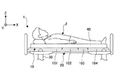
図1A及び図1Bは、一実施例によるベッド1の背上げ機能の説明図である。図1Aは、非背上げ状態を模式的に示す図であり、図1Bは、背上げ状態を模式的に示す図である。図1A及び図1Bには、ベッド1に横たわるユーザ2が示されている。尚、図1A及び図1Bは、簡易的な説明図であるので、背上げ機構等の詳細な構造は図示されていない。
1A and 1B are explanatory diagrams of the function of raising the back of the
ベッド1は、例えば介護用ベッドであり、背上げ機能を備える。背上げ機能とは、ベッド1に横たわるユーザ2の背中を下半身に対して持ち上げる機能である。背上げ機能は、ベッド1の背部10が水平な非背上げ状態から、ベッド1の背部10が水平面に対して0よりも大きい角度となる背上げ状態へと変化させ、且つ、該背上げ状態を保持できる機能である。以下、ベッド1の背部10の水平面(床面)に対する角度α(図1B参照)を、「背上げ角」と称する。背上げ機能は、複数段階又は無段階に背上げ角を調整できるものであってもよいし、1段階だけしか調整できないもの(背上げ状態か非背上げ状態かの2形態のみ)であってもよい。
The
図2は、ベッド1の構造の簡易的な説明図である。図2は、簡易的な説明図であるので、詳細な構造は図示されていない。また、図2には、背上げ機構50が概念的に簡略化して図示されている。以下では、図2に示すX,Y,及びZ軸の直交する3軸を、適宜説明に用いる。尚、Y方向は、ベッド1の幅方向に対応する。
FIG. 2 is a simplified explanatory diagram of the structure of the
ベッド1は、図2に示すように、背部10と、床に対して略水平なフレーム部20と、脚部30と、マットレス40と、背上げ機構50とを含む。
As shown in FIG. 2, the
背部10は、ユーザ2の背中をマットレス40を介して支持する背中ボトム101を含む。図2に示す例では、背中ボトム101は、1つのボトム部により形成されているが、Y軸まわりの相対回転が可能な態様で連結される複数の背中ボトム部を含んでもよい。背中ボトム101は、例えば平面状に延在する網目の金属部を含んでよい。尚、以下の説明において、背中ボトム101の平面とは、背中ボトム101の基本面であり、非背上げ状態で水平面となる面を指す。
The
背中ボトム101には、ユーザ2の尻部を支持する尻ボトム102が、Y軸まわりの相対回転が可能な態様で連結される。或いは、背中ボトム101は、尻ボトム102とは連結されなくてもよい(後述の実施例2参照)。同様に、尻ボトム102には、ユーザ2の大腿部を支持する大腿ボトム103が、Y軸まわりの相対回転が可能な態様で連結される。大腿ボトム103には、ユーザ2の下腿部を支持する下腿ボトム104が、Y軸まわりの相対回転が可能な態様で連結される。
A
フレーム部20は、例えば金属製のフレーム部材を含む。フレーム部20は、X方向に延在する複数本のフレーム部材と、Y方向に延在する複数本のフレーム部材とを含む井桁構造を有してもよい。フレーム部20は、背部10や、後述の背上げ機構50等を支持する機能を持つ。
The
脚部30は、床に対してフレーム部20を支持する。尚、脚部30は、ベッド1の簡易な移動を可能とするため、車輪を下端に含んでもよい。
The
マットレス40は、背上げ角に応じて、ある程度変形できる可撓性(即ちY軸に沿って曲がることができる可撓性)を有する。或いは、マットレス40は、背中ボトム101、尻ボトム102、大腿ボトム103、及び下腿ボトム104のそれぞれに対応して、Y軸まわりの相対回転が可能な態様(折れ曲がることが可能な態様)で連結される複数の部位を含んでもよい。マットレス40は、背中ボトム101、尻ボトム102、大腿ボトム103、及び下腿ボトム104のそれぞれの上面に下面が当接する。背中ボトム101、尻ボトム102、大腿ボトム103、及び下腿ボトム104は、協動して、マットレス40の下面の全体を支持する。即ち、背中ボトム101、尻ボトム102、大腿ボトム103、及び下腿ボトム104は、それぞれ、マットレス40が当接するマットレス支持部を形成する。
The
背上げ機構50は、上述した背上げ機能を実現する機構部である。背上げ機構50は、電動式であってもよいし、油圧式であってもよいし、手動式であってもよい。以下では、一例として、背上げ機構50は、電動式であるとする。即ち、背上げ機構50は、電動式で上述した背上げ機能を実現するものとする。
The
背上げ機構50は、上述した背上げ機能を実現できる限り、任意の構成であってよい。背上げ機構50は、例えばランバーサポート機能を備える機構(例えば、特開2005-237493号公報、特開2002-172144号公報、特開2011-244987号公報等に開示されるような機構)であってもよい。或いは、背上げ機構50は、特開2015-96201号公報や特開2007-185333号公報、特開2007-175307等に開示されるような機構であってもよい。これらの文献の背上げ機構に関する内容は、ここで参照により本願明細書に組み込まれる。
The back-raising
次に、上述したベッド1が備えることができるセンサ取り付け構造に関するいくつかの実施例について順に説明する。
Next, several examples of a sensor mounting structure that can be provided in the above-described
[実施例1]
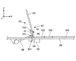
図3は、ベッド1の背上げ機構50の一例の簡易図である。図3は、簡易的な説明図であるので、詳細な構造は図示されていない。例えば、電気モータ56は概念的に簡略化して図示されている。また、図3では、背上げ状態で背上げ機構50が示されている。図4は、センサユニット90の取り付け状態の一例を示す斜視図である。[Example 1]
FIG. 3 is a simplified diagram of an example of the
背上げ機構50は、背上げアーム52と、背上げ従動アーム54と、電気モータ56とを含む。
The
背上げアーム52は、フレーム部20に下端が回転支点521によりY軸まわりに回転可能に支持される。背上げアーム52は、背中ボトム101を上端のローラ522が摺動可能に支持する。背上げアーム52が回転支点521まわりに図3の時計方向に回転駆動されると、背中ボトム101の背面を摺動しながら背中ボトム101を上方に押し上げる。
The lower end of the
背上げ従動アーム54は、同様に、フレーム部20に下端がY軸まわりに回転可能に支持される。背上げ従動アーム54は、背中ボトム101に上端がY軸まわりに回転可能に支持される。
Similarly, the lower end of the back-raising driven
電気モータ56は、背上げアーム52を回転支点521を中心としたY軸まわりに回転駆動する駆動力を発生する。電気モータ56は、電源装置60に電気的に接続される。例えば、電気モータ56は、コードないしハーネス(図示せず)を介して電源装置60に電気的に接続される。電源装置60は、例えば、フレーム部20に固定される。電源装置60は、外部の交流電源(例えば家庭用の交流電源)に電気的に接続可能であってよい。この場合、電源装置60は、外部の交流電源に基づいて、電気モータ56等を駆動するための電源を生成する。電源装置60は、外部の交流電源からの電力により充電可能なバッテリを内部に含んでもよい。この場合、電気モータ56は、バッテリからの電力に基づいて動作できる。
The
図3に示す例では、電気モータ56は、シリンダロッドを電動式に伸縮させることで背上げアーム52を回転支点521を中心としたY軸まわりに回転駆動する。シリンダロッドの上端は、背上げアーム52に回転支点561を中心としたY軸まわりに回転可能に支持される。
In the example shown in FIG. 3, the
本実施例1では、ベッド1は、センサユニット90(センサの一例)を含む。センサユニット90は、ベッド1に横たわるユーザ2の状態を検出する生体センサを含む。生体センサは、例えば電波(例えばマイクロ波)を照射し、その反射波に基づいて生体情報(ユーザ2の活動性や、呼吸、心拍等を表す情報等)を取得するセンサを含んでもよい。この場合、センサユニット90は、ベッド1に横たわるユーザ2(例えば、病人や、高齢者のような特定の人)を見守るためのシステムにおいて用いることができる。以下では、一例として、センサユニット90は、電波を照射し、その反射波に基づいて生体情報を取得する生体センサだけを含むものとする。但し、センサユニット90は、生体センサ以外の他のセンサを含んでもよい。
In the first embodiment, the
ここで、センサユニット90は、指向性を有する。ここでは、一例として、センサユニット90は、センシング面91の法線方向(向き)に指向性が最大化されており、センシング面91の法線方向を中心とした検知範囲を有するものとする。以下の説明において、センサユニット90のセンシング方向とは、センシング面91の法線方向を指す。
Here, the
図3及び図4に示す例では、センサユニット90は、背上げアーム52の上面に取り付けられる。この際、センサユニット90は、背上げ角の変化範囲の全体にわたって、センシング方向が、背中ボトム101に対して固定的な位置関係にある所定領域(以下、「心臓検知可能領域」と称する)を通るように、背上げアーム52に取り付けられる。心臓検知可能領域は、背中ボトム101の平面に対する面直視で、ベッド1に横たわるユーザ2の胸部又は心臓が位置しうる範囲に設定される(図5参照)。これにより、センサユニット90のセンシング方向がユーザ2の心臓に向かう可能性が高まる。センサユニット90のセンシング方向がユーザ2の心臓に向かう場合は、センサユニット90による検出精度を高めることができる。尚、センサユニット90の、背上げアーム52への取り付け位置や角度は、ユーザ2の体格差等を考慮して、個別に設定されてもよい。
In the example shown in FIGS. 3 and 4, the
センサユニット90の背上げアーム52への取り付け方法は、任意である。例えば、センサユニット90は、ボルトや螺子などの締結具で背上げアーム52に取り付けられてもよい。また、センサユニット90は、接着剤やテープ等により背上げアーム52に取り付けられてもよい。また、センサユニット90は、図3に模式的に示すように、背上げアーム52に直接的に取り付けられてもよいが、ステーやブラケットを介して、背上げアーム52に取り付けられてもよい。
The method of attaching the
センサユニット90は、内蔵電池により動作してもよいが、好ましくは、外部の電源装置からの電力に基づいて動作する。外部の電源装置は、好ましくは、電気モータ56に電源を供給する電源装置60である。この場合、既存の電源装置60を利用することで、専用の電源装置を新たに設けることなく、センサユニット90を動作させることができる。図3に示す例では、センサユニット90は、コードないしハーネス(図示せず)を介して電源装置60に電気的に接続される。センサユニット90は、背上げ機構50に関連した位置に設けられることから、電気モータ56の比較的近傍に設けることができるので、コードないしハーネスの配索も容易である。
The
図5は、図3の矢印Q1の方向に視たときのセンサ取り付け状態の一例を概略的に示す図である。尚、矢印Q1の方向は、背中ボトム101の平面に対する面直視に対応する。図5には、背中ボトム101と共に、背上げアーム52及びセンサユニット90が併せて示されている。また、心臓検知可能領域BT1が併せて示されている。心臓検知可能領域BT1は、図5に示す例では、ベッド1の幅方向(Y方向)の中央部に設定されている。
FIG. 5 is a diagram schematically illustrating an example of a sensor mounting state when viewed in the direction of arrow Q1 in FIG. Note that the direction of the arrow Q1 corresponds to a face direct view with respect to the plane of the
図5に示す例では、背中ボトム101は、井桁構造の構造部材である本体部1011と、縦方向の網目を形成する縦網部1012と、横方向の網目を形成する縦網部1014とを含む。尚、図5では、見易さのために、形式的に、本体部1011だけが"なし地"でハッチングされている。縦網部1012及び縦網部1014は、例えば、本体部1011に溶接され、縦網部1012及び縦網部1014は、互いに交差する位置で溶接される。図5に示す例では、背中ボトム101は、背上げアーム52のローラ522を支持するローラ支持構造524を含む。ローラ支持構造524は、2本の横フレーム部5241,5242と、2本の縦フレーム部5243,5244とを含む。縦フレーム部5243,5244の下面には、ローラ522が摺動可能に当接される。
In the example illustrated in FIG. 5, the
背上げアーム52は、背中ボトム101の下面側(マットレス40との当接側とは逆側)に位置する。背上げアーム52は、横フレーム部5241,5242は、それぞれ、互いに対してX方向に間隔をおいて、Y方向に延在する。縦フレーム部5243,5244は、それぞれ、互いに対してY方向に間隔をおいて、X方向に延在する。図5に示す例では、心臓検知可能領域BT1は、背中ボトム101の平面に対する面直視で、横フレーム部5241,5242間且つ縦フレーム部5243,5244間の領域を含む。センサユニット90は、背上げ角の変化範囲の全体にわたって、センシング方向が横フレーム部5241,5242間且つ縦フレーム部5243,5244間を通るように設けられる。これにより、背上げ角の変化範囲の全体にわたって、センサユニット90のセンシング方向が心臓検知可能領域BT1を通ることができる。尚、センサユニット90は、センシング方向が背中ボトム101の平面に対する面直方向に対応するように、背中ボトム101に対して設けられてよい。
The
ところで、センサユニット90がマットレス40の内部に設けられる比較例(図示せず)では、背上げ機構50の動作(例えば非背上げ状態から背上げ状態への移行時の動作又はその逆の動作)の際にマットレス40が変形しうる。また、背上げ機構の動作50の際にマットレス40が背中ボトム101に対して変位しうる。このため、比較例では、背上げ機構50の動作毎に、センサユニット90に比較的大きな荷重がかかり、センサユニット90の外れや位置ずれを招く虞がある。
By the way, in a comparative example (not shown) in which the
これに対して、本実施例1によれば、上述のように、センサユニット90は、マットレス40の内部ではなく、背部10を支持する支持部材である背上げアーム52に設けられる。従って、本実施例1によれば、背上げ機構50の動作に起因してセンサユニット90に荷重がかかることがなく、上述のような比較例において生じる不都合を低減できる。
On the other hand, according to the first embodiment, as described above, the
また、本実施例1によれば、上述のように、センサユニット90は、背中ボトム101の下側に設けられるので、センサユニット90がマットレス40と背中ボトム101との間に設けられる場合に比べて、センサユニット9の取り付けの信頼性が高くなる。具体的には、センサユニット90が背中ボトム101の上面に設けられる場合、非背上げ状態から背上げ状態への移行に伴い、マットレス40が背中ボトム101に対してずれると、センサユニット90の取り付け部にせん断応力が発生する。この結果、センサユニット90の取り付け部に破断等が生じやすくなる。これに対して、本実施例1では、センサユニット90はマットレス40と接触することが無いので、背中ボトム101に対するマットレス40のずれ(変位)に起因した不都合が生じない。
Further, according to the first embodiment, as described above, since the
また、本実施例1では、上述のように、センサユニット90は、背上げ角の変化範囲の全体にわたってセンシング方向が心臓検知可能領域BT1を通るように、背上げアーム52の上面に取り付けられる。従って、本実施例1によれば、非背上げ状態及び背上げ状態のいずれにおいてもユーザ2の状態をセンサユニット90により精度良く検出できる可能性が高まる。この結果、ユーザ2が寝ている間のみならず、ユーザ2が背上げ状態で座っている間も、ユーザ2の状態をセンサユニット90により精度良く検出できる可能性が高まる。
In the first embodiment, as described above, the
特に、背上げアーム52の上面は、背上げ角の変化範囲の全体にわたって、背中ボトム101の平面に対して一定の角度関係を保つ。従って、センサユニット90のセンシング方向は、背上げ角の変化範囲の全体にわたって、背中ボトム101の平面に対して一定の角度関係を保つ。また、背上げアーム52の上面におけるセンサユニット90の、背中ボトム101に対する位置は、背上げ角に応じて若干変化するだけである。従って、本実施例1では、非背上げ状態及び背上げ状態のいずれにおいてもユーザ2の状態をセンサユニット90により精度良く検出できる可能性が高まる。
In particular, the upper surface of the back-raising
また、本実施例1では、背上げアーム52は、センサユニット90の取り付けのための専用部材ではなく、既存の部材であることができる。従って、本実施例1によれば、部品点数を増加することなく、センサユニット90を適切な位置に取り付けることができる。
In the first embodiment, the
[実施例2]
図6は、ベッド1の背上げ機構50Aの一例の簡易図である。図6は、簡易的な説明図であるので、詳細な構造は図示されていない。例えば、電気モータ56Aは概念的に簡略化して図示されている。尚、図6には、背上げ機構50Aに加えて、大腿ボトム103と下腿ボトム104との間の回転支点を持ち上げる機構部82と、下腿ボトム104の自由端側を持ち上げる機構部84とが概略的に図示されている。[Example 2]
FIG. 6 is a simplified diagram of an example of the
以下の実施例2の説明において、上述した実施例1と同様であってよい構成要素については、同様の参照符号を付して説明を簡略化又は省略する。 In the following description of the second embodiment, components that may be the same as those of the above-described first embodiment are denoted by the same reference numerals, and description thereof will be simplified or omitted.
背上げ機構50Aは、背上げアーム52Aと、背上げ従動アーム54Aと、電気モータ56Aとを含む。
The
背上げアーム52Aは、フレーム部20に下端が回転支点521によりY軸まわりに回転可能に支持される。背上げアーム52Aは、背中ボトム101Aを上端のローラが摺動可能に支持する。背上げアーム52AがY軸まわりに図6の時計方向に回転駆動されると、背中ボトム101Aの背面を摺動しながら背中ボトム101Aを上方に押し上げる。
The lower end of the
背上げ従動アーム54Aは、同様に、フレーム部20に下端が回転支点541によりY軸まわりに回転可能に支持される。背上げ従動アーム54Aは、背中ボトム101Aに上端が回転可能に支持される。図6に示す例では、背上げ従動アーム54Aは、アーム支点部材542に上端が回転可能に支持される。アーム支点部材542は、背中ボトム101Aの下面側に固定される。背上げ従動アーム54Aの上端は、アーム支点部材542にY軸まわりに回転可能に支持される。このようにして、アーム支点部材542は、背中ボトム101Aの下面側から、背上げ従動アーム54Aを介して背中ボトム101Aをフレーム部20に対して支持する。
Similarly, the lower end of the back-raising driven
尚、アーム支点部材542は、背中ボトム101Aの一部として、背中ボトム101Aに一体的に形成されてもよい。例えば、アーム支点部材542は、背中ボトム101Aの一部である補強部材として具現化されてもよい。
The
電気モータ56Aは、背上げアーム52Aを回転支点521を中心としたY軸まわりに回転駆動する駆動力を発生する。電気モータ56Aは、電源装置60に電気的に接続される。
The
本実施例2では、センサユニット90は、アーム支点部材542に取り付けられる。この際、センサユニット90は、センシング方向が心臓検知可能領域BT1を通るように、アーム支点部材542に取り付けられる。尚、センサユニット90の、アーム支点部材542への取り付け位置や角度は、ユーザ2の体格差等を考慮して、個別に設定されてもよい。
In the second embodiment, the
センサユニット90のアーム支点部材542への取り付け方法は、任意である。例えば、センサユニット90は、ボルトや螺子などの締結具でアーム支点部材542に取り付けられてもよい。また、センサユニット90は、接着剤やテープ等によりアーム支点部材542に取り付けられてもよい。また、センサユニット90は、図6に模式的に示すように、アーム支点部材542に直接的に取り付けられてもよいが、後述のように、ステーやブラケットを介して、アーム支点部材542に取り付けられてもよい。
The method of attaching the
図7は、図6の矢印Q2の方向に視たときのセンサ取り付け状態の一例を概略的に示す図である。尚、矢印Q2の方向は、背中ボトム101Aの平面に対する面直視に対応する。図7には、背中ボトム101Aと共に、アーム支点部材542及びセンサユニット90が併せて示されている。また、心臓検知可能領域BT1が併せて示されている。心臓検知可能領域BT1は、図7に示す例では、ベッド1の幅方向(Y方向)の中央部に設定されている。
FIG. 7 is a diagram schematically illustrating an example of the sensor mounting state when viewed in the direction of arrow Q2 in FIG. Note that the direction of the arrow Q2 corresponds to a face direct view with respect to the plane of the
図7に示す例では、背中ボトム101Aは、本体部1011と、縦網部1012と、縦網部1014とを含む。アーム支点部材542は、背中ボトム101Aの下面側(マットレス40との当接側とは逆側)に固定される。アーム支点部材542は、2本の横フレーム部5421,5422と、縦フレーム部5423とを含む。横フレーム部5421,5422は、それぞれ、互いに対してX方向に間隔をおいて、Y方向に延在する。縦フレーム部5423は、横フレーム部5421,5422のそれぞれのY方向の中央部間に延在する。縦フレーム部5423は、横フレーム部5421,5422の下面側に固定される。このとき、縦フレーム部5423と背中ボトム101Aとの間には、背中ボトム101Aの平面に対する面直方向で隙間が形成される。図7に示す例では、センサユニット90は、該隙間を利用して、縦フレーム部5423と背中ボトム101Aとの間に設けられる。例えば、センサユニット90は、縦フレーム部5423の上面に固定される。
In the example illustrated in FIG. 7, the
尚、図7に示す例では、センサユニット90は、センシング方向が背中ボトム101Aの平面に対する面直方向に対応するように、背中ボトム101Aに対して設けられる。これにより、センサユニット90のセンシング方向が心臓検知可能領域BT1を通ることができる。
In the example shown in FIG. 7, the
ところで、本実施例2のように背上げ機構50Aを備えたベッド1の場合、マットレス40に対するユーザ2の体の相対位置は、背上げ角度に応じて変化しうる。例えば、ユーザ2の姿勢が、非背上げ状態における仰臥位の場合(図1A参照)と、背上げ状態における座位の場合(図1Bの場合)とでは、マットレス40と体との位置関係がずれる虞がある。これは、非背上げ状態から背上げ状態への移行の際に、ユーザ2の体がマットレス40(特に持ち上げられる背中側の部位)に対してずれるためである。このため、例えばマットレス40の内部にセンサユニット90を設ける比較例では、背上げ角度によっては、高い検出精度を維持することが難しい。
By the way, in the case of the
これに対して、本実施例2によれば、上述のように、センサユニット90は、マットレス40の内部ではなく、背中ボトム101Aに対して固定される部材、即ちアーム支点部材542に設けられる。従って、本実施例2によれば、背中ボトム101Aに対するセンサユニット90のセンシング方向は、背上げ角に応じて変化しない。換言すると、本実施例2によれば、センサユニット90のセンシング方向は、背上げ角の如何に拘らず、心臓検知可能領域BT1を通ることができる。
On the other hand, according to the second embodiment, as described above, the
ここで、背中ボトム101Aに対するユーザ2の体の相対位置は、マットレス40に対するユーザ2の体の相対位置とは異なり、背上げ角度に応じて変化し難い。これは、非背上げ状態から背上げ状態への移行の際、ユーザ2の体がマットレス40に対してずれる方向は、マットレス40が背中ボトム101Aに対してずれる方向(ずり落ちる方向)と逆方向である傾向があるためである。従って、本実施例2によれば、非背上げ状態及び背上げ状態のいずれにおいてもユーザ2の状態をセンサユニット90により精度良く検出できる可能性が高まる。この結果、ユーザ2が寝ている間のみならず、ユーザ2が背上げ状態で座っている間も、ユーザ2の状態をセンサユニット90により精度良く検出できる可能性が高まる。
Here, the relative position of the body of the
また、本実施例2では、センサユニット90は、マットレス40の内部ではなく、アーム支点部材542に設けられることから、背上げ機構50の動作に起因してセンサユニット90に荷重がかかることがない。これにより、背上げ機構50の動作に起因したセンサユニット90の外れや位置ずれを低減できる。センサユニット90は、上述した実施例1と同様、背中ボトム101Aの下側に設けられる。これにより、センサユニット90がマットレス40と背中ボトム101Aとの間に設けられる場合に比べて、センサユニット9の取り付けの信頼性が高くなる。
In the second embodiment, since the
また、本実施例2では、上述した実施例1と同様、アーム支点部材542は、センサユニット90の取り付けのための専用部材ではなく、既存の部材であることができる。従って、本実施例2によれば、部品点数を増加することなく、センサユニット90を適切な位置に取り付けることができる。
In the second embodiment, similarly to the first embodiment, the
尚、上述した実施例2では、センサユニット90は、アーム支点部材542に取り付けられているが、これに限られない。例えば、センサユニット90は、背中ボトム101Aの形成する部材(例えば、図7に示す例では、本体部1011、縦網部1012,縦網部1014等)に取り付けられてもよい。この場合、センサユニット90は、好ましくは、マットレス40と接触しないように、背中ボトム101Aの形成する部材の下面側に取り付けられる。
In the above-described second embodiment, the
また、上述した実施例2では、センサユニット90は、ベッド1の既存の部材(即ち、ベッド1の強度や機能を維持するための構造上、必要な部材)に直接的に取り付けられているが、これに限られない。センサユニット90は、例えば背中ボトム101Aに固定される専用の部材に取り付けられてもよい。かかる専用の部材は、例えば、背中ボトム101Aに対するアーム支点部材542の位置が、心臓検知可能領域BT1に対して離れている場合に好適となる。この場合、専用の部材は、アーム支点部材542から心臓検知可能領域BT1に向けて延在する態様で設けられる。
In the second embodiment described above, the
尚、上述した実施例2では、センサユニット90は、背中ボトム101Aに対して固定された部材(例えばアーム支点部材542)に取り付けられるが、背上げ角に応じて背中ボトム101Aに対して変位する可動部材に取り付けられてもよい。即ち、センサユニット90は、上述した実施例1と同様に、例えば背上げ機構50Aの可動部材に取り付けられてもよい。これは、背上げ角に応じて背中ボトム101Aに対して変位する可動部材であっても、その変位の量や方向によっては、センサユニット90のセンシング方向は、背上げ角の如何に拘らず、心臓検知可能領域BT1を通ることができるためである。この場合も、センサユニット90がマットレス40と接触しないように取り付けできれば、マットレス40の背中ボトム101に対するずれ(変位)に起因した不都合が生じない。
In the second embodiment described above, the
以上、各実施例について詳述したが、特定の実施例に限定されるものではなく、特許請求の範囲に記載された範囲内において、種々の変形及び変更が可能である。また、前述した実施例の構成要素を全部又は複数を組み合わせることも可能である。 As described above, each embodiment has been described in detail. However, the present invention is not limited to a specific embodiment, and various modifications and changes can be made within the scope described in the claims. It is also possible to combine all or a plurality of the components of the above-described embodiment.
例えば、上述した実施例1(実施例2についても同様)において、ベッド1は、背部10の高さを調整する機構を備えてもよい。
For example, in the above-described first embodiment (the same applies to the second embodiment), the
1 ベッド
2 ユーザ
9 センサユニット
10 背部
20 フレーム部
30 脚部
40 マットレス
50 背上げ機構
50A 背上げ機構
52 背上げアーム
52A 背上げアーム
54 アーム支点部材
54 背上げ従動アーム
54A 背上げ従動アーム
56 電気モータ
56A 電気モータ
60 電源装置
90 センサユニット
91 センシング面
101 背中ボトム
101A 背中ボトム
102 尻ボトム
103 大腿ボトム
104 下腿ボトム
522 ローラ
524 ローラ支持構造
542 アーム支点部材1
Claims (5)
前記背上げ機構は、前記ベッドの背部を床面から持ち上げて支持する支持部材を有し、
前記ベッドの背部は、マットレスが当接するマットレス支持部を有し、
前記支持部材に取り付けられ、前記ベッドに横たわるユーザの状態を検出する生体センサを有し、
前記生体センサは、前記マットレス支持部に対するセンシングの方向の向きが、前記ベッドの背部の前記床面に対する背上げ角に応じて変化しないように、前記支持部材に取り付けられたことを特徴とするベッド。 In a bed with a back raising mechanism,
The back lifting mechanism has a support member that lifts and supports the back of the bed from the floor,
The back of the bed has a mattress support portion against which the mattress abuts,
A living body sensor attached to the support member and detecting a state of a user lying on the bed ,
The bed, wherein the biological sensor is attached to the support member such that a direction of a sensing direction with respect to the mattress support portion does not change according to a back-up angle of a back portion of the bed with respect to the floor surface. .
前記生体センサは、前記背上げ機構を動作させる電気モータと同一の電源装置に電気的に接続される、ことを特徴とする請求項1〜3のいずれかに記載のベッド。 The back lifting mechanism is electrically operated,
The bed according to any one of claims 1 to 3, wherein the living body sensor is electrically connected to the same power supply as an electric motor that operates the back lifting mechanism.
前記ベッドの背部を床面から持ち上げて支持する前記背上げ機構のアームと、
前記アームに取り付けられ、前記ベッドに横たわるユーザの状態を検出する生体センサと、
を備え、
前記アームは、前記背部を摺動可能に支持する2つのローラであって、前記ベッドの幅方向に離間した2つのローラを含み、
前記生体センサは、前記ベッドの幅方向で2つの前記ローラの間に位置することを特徴とするベッド。 In a bed with a back raising mechanism,
An arm of the back lifting mechanism for supporting the back of the bed by lifting it from the floor,
A biological sensor attached to the arm and detecting a state of a user lying on the bed ;
With
The arm includes two rollers that slidably support the back, and includes two rollers that are separated in a width direction of the bed.
The biometric sensors, bed, characterized in that located between two of said rollers in the width direction of the bed.
Applications Claiming Priority (1)
| Application Number | Priority Date | Filing Date | Title |
|---|---|---|---|
| PCT/JP2015/086015 WO2017109894A1 (en) | 2015-12-24 | 2015-12-24 | Bed |
Publications (2)
| Publication Number | Publication Date |
|---|---|
| JPWO2017109894A1 JPWO2017109894A1 (en) | 2018-07-12 |
| JP6677261B2 true JP6677261B2 (en) | 2020-04-08 |
Family
ID=59089748
Family Applications (1)
| Application Number | Title | Priority Date | Filing Date |
|---|---|---|---|
| JP2017557586A Active JP6677261B2 (en) | 2015-12-24 | 2015-12-24 | bed |
Country Status (3)
| Country | Link |
|---|---|
| US (1) | US11135109B2 (en) |
| JP (1) | JP6677261B2 (en) |
| WO (1) | WO2017109894A1 (en) |
Families Citing this family (2)
| Publication number | Priority date | Publication date | Assignee | Title |
|---|---|---|---|---|
| CN114502039A (en) * | 2019-09-18 | 2022-05-13 | 斯迪尔科斯公司 | Body support member with lattice construction |
| TWI803397B (en) * | 2022-07-21 | 2023-05-21 | 施權航 | electric bed |
Family Cites Families (111)
| Publication number | Priority date | Publication date | Assignee | Title |
|---|---|---|---|---|
| US3460314A (en) * | 1966-10-17 | 1969-08-12 | Anderson Bros Mfg Co | Lid dispensing apparatus |
| US3518435A (en) * | 1967-11-24 | 1970-06-30 | Philips Corp | Automatic x-radiation collimating apparatus responsive to film cassette size |
| US3658133A (en) * | 1968-12-10 | 1972-04-25 | Ralph Sweet | Automatic depth control device for tillage units |
| US3772972A (en) * | 1972-03-20 | 1973-11-20 | Taylor M L | Stacker |
| US3913729A (en) * | 1972-08-11 | 1975-10-21 | Cambridge Wire Cloth | Belt aligner |
| US4030353A (en) * | 1975-03-03 | 1977-06-21 | Western Gear Corporation | Effort limiting and interrupting actuator |
| JPS51127988A (en) * | 1975-04-30 | 1976-11-08 | Ishikawajima Harima Heavy Ind Co Ltd | Tension control device having looper and this looper |
| US4031752A (en) * | 1976-07-19 | 1977-06-28 | Art Sanders | Web process control apparatus |
| SE396301B (en) * | 1976-12-30 | 1977-09-19 | Bulten Kanthal Ab | WAY TO TURN OR REORIENT THE LAST CHAIN LINK RESP A LINK OF A FREELY HANGING CHAIN JEMTING DEVICE FOR IMPLEMENTING THE KIT |
| US4173972A (en) * | 1977-09-09 | 1979-11-13 | Katsuji Kodera | Massaging machine |
| US4197691A (en) * | 1978-09-25 | 1980-04-15 | Hagie Manufacturing Co. | Detasseling device depth adjusting control system and method |
| US4230098A (en) * | 1979-02-13 | 1980-10-28 | Kazuma Uematsu | Rhythmical traction type device for medical treatment |
| US4307961A (en) * | 1979-04-02 | 1981-12-29 | Western Electric Company, Inc. | Apparatus for precisely aligning a pair of elements |
| FR2454867A1 (en) * | 1979-04-27 | 1980-11-21 | Usinor | MACHINE FOR SLENDING SLABS BY OXY CUTTING |
| FR2459152A1 (en) * | 1979-06-18 | 1981-01-09 | Bennes Marrel | IMPROVED HANDLING DEVICE MOUNTED ON VEHICLE FOR HANDLING LOADS SUCH AS BINS AND CONTAINERS |
| DE3065621D1 (en) * | 1979-09-25 | 1983-12-22 | Faiveley Sa | Automatic wire-engaging device for an electrical vehicle of the trolleybus type |
| CH643722A5 (en) * | 1979-11-28 | 1984-06-29 | Inpaver Ag | LOUNGE FURNITURE. |
| US4463463A (en) * | 1980-03-28 | 1984-08-07 | Aisin Seiki Kabushiki Kaisha | Adjustable bed |
| US4407030A (en) * | 1981-02-09 | 1983-10-04 | Maxwell Products, Inc. | Safety device for an adjustable bed |
| JPS60222979A (en) * | 1984-04-19 | 1985-11-07 | Toshiba Corp | Information reader |
| US4637144A (en) * | 1984-07-03 | 1987-01-20 | Schaudt Maschinenbau Gmbh | Apparatus for monitoring the diameters of crankpins during treatment in grinding machines |
| US4656998A (en) * | 1984-10-05 | 1987-04-14 | France Bed Co., Ltd. | Foldable massage bed with reciprocating rollers |
| JPS61146257A (en) * | 1984-12-19 | 1986-07-03 | 松下電工株式会社 | Massage chair |
| GB8509326D0 (en) * | 1985-04-11 | 1985-05-15 | Drexel Equipment Ltd | Centralizing device |
| US5020518A (en) * | 1990-02-09 | 1991-06-04 | Integrity Health Systems Corporation | Travelling roller massage apparatus |
| JPH03264005A (en) * | 1990-03-14 | 1991-11-25 | Paramount Bed Co Ltd | Emergency stop mechanism of bed |
| US5137016A (en) * | 1991-02-28 | 1992-08-11 | Kabushiki Kaisha Japan Health | Automatic multifunction massager for chair |
| US5321980A (en) * | 1991-05-10 | 1994-06-21 | Williams Controls, Inc. | Integrated throttle position sensor with independent position validation sensor |
| US5342036A (en) * | 1991-10-09 | 1994-08-30 | Roll Systems, Inc. | High capacity sheet feeders for high volume printers |
| US5320641A (en) * | 1992-02-28 | 1994-06-14 | Riddle & Withrow, Inc. | Computer controlled physical therapy device |
| DE9300438U1 (en) * | 1993-01-15 | 1993-03-11 | Dewert Antriebs- Und Systemtechnik Gmbh & Co. Kg, 4983 Kirchlengern, De | |
| US5544376A (en) * | 1994-01-31 | 1996-08-13 | Maxwell Products, Inc. | Articulated bed with customizable remote control |
| US5792080A (en) * | 1994-05-18 | 1998-08-11 | Matsushita Electric Works, Ltd. | Massaging apparatus having self-adjusting constant strength and non-adjust strength modes |
| US6038718A (en) * | 1994-08-15 | 2000-03-21 | Midmark Corporation | Surgical table |
| US5468216A (en) * | 1994-10-12 | 1995-11-21 | Physicians Consulting Incorporated | Kinetic rehabilitation device employing controlled passive motion |
| US5584442A (en) * | 1995-04-24 | 1996-12-17 | Eastman Kodak Company | Apparatus and method for preparing strips of web and winding them into a cartridge |
| US6047424A (en) * | 1995-08-04 | 2000-04-11 | Hill-Rom, Inc. | Bed having modular therapy devices |
| TW358026B (en) * | 1996-09-30 | 1999-05-11 | Sanyo Electric Co | Massage apparatus |
| JP4209587B2 (en) * | 1997-09-12 | 2009-01-14 | オートリブ株式会社 | Body acceleration sensor for seat belt |
| US6101647A (en) * | 1998-03-10 | 2000-08-15 | L&P Property Management Company | Adjustable bed |
| US6393641B1 (en) * | 1998-04-22 | 2002-05-28 | Hill-Rom Services, Inc. | Articulating bed frame |
| EP0990435B1 (en) * | 1998-04-27 | 2004-12-22 | Toshiba Tec Kabushiki Kaisha | Positioning device and massaging machine having the device |
| JP2953581B1 (en) * | 1998-11-13 | 1999-09-27 | パラマウントベッド株式会社 | Back raising mechanism in bed |
| US6659939B2 (en) * | 1998-11-20 | 2003-12-09 | Intuitive Surgical, Inc. | Cooperative minimally invasive telesurgical system |
| JP4249872B2 (en) * | 1999-09-09 | 2009-04-08 | ファミリー株式会社 | Massage machine |
| US6276011B1 (en) * | 2000-03-17 | 2001-08-21 | Santino Antinori | Adjustable bed and adjustable frame therefor |
| US6645047B1 (en) * | 2000-03-20 | 2003-11-11 | Control Gaging, Inc. | Automatic gage head positioning system |
| US6494851B1 (en) * | 2000-04-19 | 2002-12-17 | James Becher | Real time, dry mechanical relaxation station and physical therapy device simulating human application of massage and wet hydrotherapy |
| US7066898B2 (en) * | 2000-06-30 | 2006-06-27 | Omron Corporation | Vibrator, vibration unit, and vibrator control method |
| JP4020581B2 (en) * | 2000-11-15 | 2007-12-12 | 三洋電機株式会社 | Chair type massage machine |
| CA2361853C (en) * | 2000-11-15 | 2010-05-25 | Ceragem International, Inc. | Roller type hyperthermo-radiative apparatus for a mat for hot compress and acupressure |
| FR2819173B1 (en) * | 2001-01-09 | 2003-04-11 | Alm | MULTI-SECTIONS MOTORIZED OPERATING TABLE |
| JP4017350B2 (en) * | 2001-02-09 | 2007-12-05 | 三洋電機株式会社 | Massage machine |
| US7038588B2 (en) * | 2001-05-04 | 2006-05-02 | Draeger Medical Infant Care, Inc. | Apparatus and method for patient point-of-care data management |
| EP1297812A1 (en) * | 2001-10-01 | 2003-04-02 | Hoerbiger Micro Fluid GmbH | Adjustable patient-supporting device |
| US8095204B2 (en) * | 2002-08-09 | 2012-01-10 | Interstitial, Llc | Apparatus and method for diagnosing breast cancer including examination table |
| EP1585473B1 (en) * | 2002-09-06 | 2012-10-24 | Hill-Rom Services, Inc. | Hospital bed |
| US20040158176A1 (en) * | 2003-01-29 | 2004-08-12 | Joon Park | Hot acupressure and massage machine |
| JP4167507B2 (en) * | 2003-02-19 | 2008-10-15 | フランスベッド株式会社 | Wake-up bed equipment |
| US7036165B2 (en) * | 2003-04-02 | 2006-05-02 | L&P Property Management Company | Adjustable bed with automatic adjusting head section |
| TWI236371B (en) * | 2003-05-27 | 2005-07-21 | Matsushita Electric Works Ltd | Massaging device |
| US7022921B2 (en) * | 2003-05-28 | 2006-04-04 | Sr Instruments, Inc. | Electronic scale assembly having incorporated spreader arm |
| JP4096816B2 (en) * | 2003-06-04 | 2008-06-04 | 松下電工株式会社 | Massage machine |
| US7093485B2 (en) * | 2003-11-17 | 2006-08-22 | Nartron Corporation | Fuel level sensor |
| CA2493696A1 (en) * | 2004-01-22 | 2005-07-22 | Hill-Rom Services, Inc. | Movable control panel for a patient support |
| US7496457B2 (en) * | 2004-03-25 | 2009-02-24 | Delta Tooling Co., Ltd. | Load body state judging device, vehicle seat and computer program |
| US7253366B2 (en) * | 2004-08-09 | 2007-08-07 | Hill-Rom Services, Inc. | Exit alarm for a hospital bed triggered by individual load cell weight readings exceeding a predetermined threshold |
| US7600817B2 (en) * | 2004-08-16 | 2009-10-13 | Hill-Rom Services, Inc. | Chair |
| US7176391B2 (en) * | 2004-09-13 | 2007-02-13 | Hill-Rom Services, Inc. | Load cell to frame interface for hospital bed |
| US7743441B2 (en) * | 2004-09-13 | 2010-06-29 | Kreg Therapeutics, Inc. | Expandable width bed |
| JP4483548B2 (en) * | 2004-11-25 | 2010-06-16 | パナソニック電工株式会社 | Massage machine |
| TW200701974A (en) * | 2005-06-20 | 2007-01-16 | Family Co Ltd | Chair type massaging machine, massaging machine, operation device of chair type massaging machine, remote controller for chair type massaging machine |
| CA2616700A1 (en) * | 2005-08-09 | 2007-02-15 | Gil Zwirn | High resolution radio frequency medical imaging and therapy system |
| JP2007175307A (en) * | 2005-12-28 | 2007-07-12 | Shinei Kogyo Kk | Raising/lowering device of bed |
| US20070239089A1 (en) * | 2006-03-30 | 2007-10-11 | Yu-Mei Chiu | Massage mechanism for massage chair |
| US7559899B2 (en) * | 2006-04-12 | 2009-07-14 | Salutron, Inc. | Power saving techniques for continuous heart rate monitoring |
| WO2007133552A2 (en) * | 2006-05-09 | 2007-11-22 | Hill-Rom Services, Inc. | Pulmonary mattress |
| WO2008024561A2 (en) * | 2006-07-05 | 2008-02-28 | Stryker Corporation | A system for detecting and monitoring vital signs |
| US20080009777A1 (en) * | 2006-07-06 | 2008-01-10 | Yu-Mei Chiu | Massage chair mechanism |
| JP4731422B2 (en) * | 2006-08-01 | 2011-07-27 | 三洋電機株式会社 | Chair type massage machine |
| US20100171622A1 (en) * | 2006-08-14 | 2010-07-08 | Koninklijke Philips Electronics N.V. | bed with intefrated sensor unit for a patient |
| JP4793650B2 (en) * | 2006-11-07 | 2011-10-12 | アイシン精機株式会社 | Physical condition management system |
| JP2008131974A (en) * | 2006-11-27 | 2008-06-12 | Showa Denko Kk | Bed for respiration trouble or the like during sleeping |
| US7806840B2 (en) * | 2006-11-28 | 2010-10-05 | Ko-Po Chen | Massage device for rubbing, beating and kneading |
| JP5063316B2 (en) * | 2007-04-19 | 2012-10-31 | パナソニック株式会社 | Massage equipment |
| US20080269629A1 (en) * | 2007-04-25 | 2008-10-30 | Robert Howard Reiner | Multimodal therapeutic and feedback system |
| US7836531B2 (en) * | 2007-08-01 | 2010-11-23 | Stryker Corporation | CPR drop mechanism for a hospital bed |
| US20090306558A1 (en) * | 2008-06-06 | 2009-12-10 | Ko-Po Chen | Massage device for a massage chair |
| US20120116257A1 (en) * | 2009-03-05 | 2012-05-10 | Searete Llc | Postural information system and method including determining response to subject advisory information |
| US8752220B2 (en) * | 2009-07-10 | 2014-06-17 | Hill-Rom Services, Inc. | Systems for patient support, monitoring and treatment |
| US8585588B2 (en) * | 2009-11-18 | 2013-11-19 | Nohands, Llc | Method and system for preventing virus-related obesity and obesity related diseases |
| JP2011110068A (en) * | 2009-11-24 | 2011-06-09 | Sumitomo Electric Ind Ltd | Monitoring device and body support device |
| US8419300B2 (en) * | 2009-12-21 | 2013-04-16 | Xerox Corporation | Modular web roller assembly |
| JP5572760B2 (en) * | 2010-06-09 | 2014-08-13 | コリア インスティチュート オブ インダストリアル テクノロジー | Electric bed platform for preventing bedsores whose rotation axis is variable according to the user's body shape, and control method of the posture change period |
| US8266743B2 (en) * | 2010-08-23 | 2012-09-18 | Midmark Corporation | Examination table with motion tracking |
| KR101181918B1 (en) * | 2010-11-09 | 2012-09-11 | 주식회사 세라젬 | Moving up and down apparatus for a hyperthermo-therapeutic apparatus |
| US8959681B2 (en) * | 2010-12-20 | 2015-02-24 | Hill-Rom Services, Inc. | Ground sensor control of foot section retraction |
| US8551028B2 (en) * | 2011-04-15 | 2013-10-08 | Ko-Po Chen | Force sensing mechansim of a massage machine |
| ES2537734T3 (en) * | 2011-06-01 | 2015-06-11 | David MIJAN | Vibration system and method of a bed |
| WO2013033358A1 (en) * | 2011-08-30 | 2013-03-07 | Street Smart Sensors Llc | Ultrasonic liquid level detector |
| CN202776940U (en) * | 2012-08-13 | 2013-03-13 | 林丹鹏 | Massage device with massage dynamic perception driving mechanism |
| US10292605B2 (en) * | 2012-11-15 | 2019-05-21 | Hill-Rom Services, Inc. | Bed load cell based physiological sensing systems and methods |
| JP6353194B2 (en) | 2013-04-22 | 2018-07-04 | 公立大学法人首都大学東京 | Physical information measuring device |
| WO2014189969A1 (en) * | 2013-05-21 | 2014-11-27 | Camplex, Inc. | Surgical visualization systems |
| CN203710325U (en) * | 2013-08-14 | 2014-07-16 | 宁波康福特健身器械有限公司 | Massage chair |
| US10092480B2 (en) * | 2013-12-11 | 2018-10-09 | Luraco, Inc. | Touchscreen-based control system for massage chairs |
| US9028407B1 (en) * | 2013-12-13 | 2015-05-12 | Safer Care LLC | Methods and apparatus for monitoring patient conditions |
| US9132051B2 (en) * | 2014-01-15 | 2015-09-15 | Hill-Rom Services, Inc. | Person support apparatuses with exercise functionalities |
| CA2902102C (en) * | 2014-08-27 | 2023-02-14 | Umano Medical Inc. | Systems for patient support surface orientation and displacement |
| WO2017019049A1 (en) * | 2015-07-29 | 2017-02-02 | Abou El Kheir Tarek Ahmed Nabil | Advanced 3-dimensional endoscopic system with real dynamic convergence |
| US11147719B2 (en) * | 2015-11-16 | 2021-10-19 | Hill-Rom Services, Inc. | Incontinence detection systems for hospital beds |
-
2015
- 2015-12-24 JP JP2017557586A patent/JP6677261B2/en active Active
- 2015-12-24 WO PCT/JP2015/086015 patent/WO2017109894A1/en active Application Filing
-
2018
- 2018-06-05 US US16/000,232 patent/US11135109B2/en active Active
Also Published As
| Publication number | Publication date |
|---|---|
| US11135109B2 (en) | 2021-10-05 |
| JPWO2017109894A1 (en) | 2018-07-12 |
| US20180280218A1 (en) | 2018-10-04 |
| WO2017109894A1 (en) | 2017-06-29 |
Similar Documents
| Publication | Publication Date | Title |
|---|---|---|
| JP4985107B2 (en) | Bed equipment | |
| US20100281613A1 (en) | Patient positioning device | |
| CN109938945A (en) | A kind of Multi-functional wheel chair bed | |
| US11304864B2 (en) | Patient support systems with a chair configuration and a stowable foot section | |
| US9333139B2 (en) | Patient positioning device | |
| EP3462990B1 (en) | A bed, bed assembly method, and bed usage method | |
| JP6677261B2 (en) | bed | |
| TW201315412A (en) | Bed device | |
| JP2007054606A (en) | Biological signal detecting apparatus | |
| JP2009201889A (en) | Caregiving bed | |
| US10729606B2 (en) | Adaptive mobility lift | |
| KR101224447B1 (en) | Eletrically driven medical bed with tilting function | |
| JP2008131974A (en) | Bed for respiration trouble or the like during sleeping | |
| JP3026496B1 (en) | Bed with back raising mechanism | |
| KR101639489B1 (en) | Bed for medical purposes | |
| JP2007061361A (en) | Caring bed | |
| JP6706536B2 (en) | User position detecting device and method | |
| US20200069490A1 (en) | Control system for a lifting chair | |
| JP6668179B2 (en) | Foot bottom support structure and bed apparatus | |
| JP6581459B2 (en) | Bed equipment | |
| JP6070097B2 (en) | Sleeping posture determination device and sleeping posture determination method | |
| CN208464483U (en) | A kind of system for turning over of nursing bed | |
| JP2008099957A (en) | Sheet for measuring biometric information | |
| TWI754314B (en) | Lifting aid device and its method | |
| JP7142324B2 (en) | chair traction device |
Legal Events
| Date | Code | Title | Description |
|---|---|---|---|
| A521 | Request for written amendment filed |
Free format text: JAPANESE INTERMEDIATE CODE: A523 Effective date: 20180328 |
|
| A621 | Written request for application examination |
Free format text: JAPANESE INTERMEDIATE CODE: A621 Effective date: 20180328 |
|
| A131 | Notification of reasons for refusal |
Free format text: JAPANESE INTERMEDIATE CODE: A131 Effective date: 20190604 |
|
| A521 | Request for written amendment filed |
Free format text: JAPANESE INTERMEDIATE CODE: A523 Effective date: 20190716 |
|
| A131 | Notification of reasons for refusal |
Free format text: JAPANESE INTERMEDIATE CODE: A131 Effective date: 20191119 |
|
| A521 | Request for written amendment filed |
Free format text: JAPANESE INTERMEDIATE CODE: A523 Effective date: 20191225 |
|
| TRDD | Decision of grant or rejection written | ||
| A01 | Written decision to grant a patent or to grant a registration (utility model) |
Free format text: JAPANESE INTERMEDIATE CODE: A01 Effective date: 20200212 |
|
| A61 | First payment of annual fees (during grant procedure) |
Free format text: JAPANESE INTERMEDIATE CODE: A61 Effective date: 20200225 |
|
| R150 | Certificate of patent or registration of utility model |
Ref document number: 6677261 Country of ref document: JP Free format text: JAPANESE INTERMEDIATE CODE: R150 |