JP6676123B2 - Respiratory treatment system - Google Patents
Respiratory treatment system Download PDFInfo
- Publication number
- JP6676123B2 JP6676123B2 JP2018188219A JP2018188219A JP6676123B2 JP 6676123 B2 JP6676123 B2 JP 6676123B2 JP 2018188219 A JP2018188219 A JP 2018188219A JP 2018188219 A JP2018188219 A JP 2018188219A JP 6676123 B2 JP6676123 B2 JP 6676123B2
- Authority
- JP
- Japan
- Prior art keywords
- outlet
- connector
- tube
- present technology
- cable
- Prior art date
- Legal status (The legal status is an assumption and is not a legal conclusion. Google has not performed a legal analysis and makes no representation as to the accuracy of the status listed.)
- Active
Links
- 230000000241 respiratory effect Effects 0.000 title claims description 52
- 230000006870 function Effects 0.000 claims description 34
- 238000010438 heat treatment Methods 0.000 claims description 24
- 230000029058 respiratory gaseous exchange Effects 0.000 claims description 17
- 230000014759 maintenance of location Effects 0.000 claims description 13
- 229920002725 thermoplastic elastomer Polymers 0.000 claims description 10
- 238000002644 respiratory therapy Methods 0.000 claims description 9
- 230000008054 signal transmission Effects 0.000 claims description 8
- 238000005516 engineering process Methods 0.000 description 275
- 239000007789 gas Substances 0.000 description 52
- 238000012384 transportation and delivery Methods 0.000 description 39
- 238000000034 method Methods 0.000 description 34
- 239000000463 material Substances 0.000 description 32
- 230000015572 biosynthetic process Effects 0.000 description 30
- 238000005755 formation reaction Methods 0.000 description 30
- 238000000465 moulding Methods 0.000 description 25
- XLYOFNOQVPJJNP-UHFFFAOYSA-N water Substances O XLYOFNOQVPJJNP-UHFFFAOYSA-N 0.000 description 20
- 238000009423 ventilation Methods 0.000 description 18
- QVGXLLKOCUKJST-UHFFFAOYSA-N atomic oxygen Chemical compound [O] QVGXLLKOCUKJST-UHFFFAOYSA-N 0.000 description 16
- 229910052760 oxygen Inorganic materials 0.000 description 15
- 239000001301 oxygen Substances 0.000 description 15
- 230000033001 locomotion Effects 0.000 description 13
- CURLTUGMZLYLDI-UHFFFAOYSA-N Carbon dioxide Chemical compound O=C=O CURLTUGMZLYLDI-UHFFFAOYSA-N 0.000 description 12
- 208000023504 respiratory system disease Diseases 0.000 description 10
- 238000004519 manufacturing process Methods 0.000 description 9
- 239000004417 polycarbonate Substances 0.000 description 9
- 238000002560 therapeutic procedure Methods 0.000 description 9
- XECAHXYUAAWDEL-UHFFFAOYSA-N acrylonitrile butadiene styrene Chemical compound C=CC=C.C=CC#N.C=CC1=CC=CC=C1 XECAHXYUAAWDEL-UHFFFAOYSA-N 0.000 description 8
- 239000004676 acrylonitrile butadiene styrene Substances 0.000 description 8
- 229920000122 acrylonitrile butadiene styrene Polymers 0.000 description 8
- 230000000295 complement effect Effects 0.000 description 8
- 238000003780 insertion Methods 0.000 description 8
- 230000037431 insertion Effects 0.000 description 8
- 230000008569 process Effects 0.000 description 8
- 210000002345 respiratory system Anatomy 0.000 description 8
- 238000007789 sealing Methods 0.000 description 8
- 229920002379 silicone rubber Polymers 0.000 description 8
- 230000008901 benefit Effects 0.000 description 7
- 238000004891 communication Methods 0.000 description 7
- 239000000356 contaminant Substances 0.000 description 7
- 230000006378 damage Effects 0.000 description 7
- 208000037265 diseases, disorders, signs and symptoms Diseases 0.000 description 7
- 210000001331 nose Anatomy 0.000 description 7
- 230000000153 supplemental effect Effects 0.000 description 7
- 238000011144 upstream manufacturing Methods 0.000 description 7
- 208000027418 Wounds and injury Diseases 0.000 description 6
- 229910002092 carbon dioxide Inorganic materials 0.000 description 6
- 239000001569 carbon dioxide Substances 0.000 description 6
- 238000013461 design Methods 0.000 description 6
- 201000010099 disease Diseases 0.000 description 6
- 210000000214 mouth Anatomy 0.000 description 6
- 208000018360 neuromuscular disease Diseases 0.000 description 6
- 208000001797 obstructive sleep apnea Diseases 0.000 description 6
- 208000006545 Chronic Obstructive Pulmonary Disease Diseases 0.000 description 5
- 239000004944 Liquid Silicone Rubber Substances 0.000 description 5
- 208000004756 Respiratory Insufficiency Diseases 0.000 description 5
- 238000005452 bending Methods 0.000 description 5
- 238000010586 diagram Methods 0.000 description 5
- 210000004072 lung Anatomy 0.000 description 5
- 229920000515 polycarbonate Polymers 0.000 description 5
- 230000002829 reductive effect Effects 0.000 description 5
- 201000004193 respiratory failure Diseases 0.000 description 5
- 206010008501 Cheyne-Stokes respiration Diseases 0.000 description 4
- 208000000059 Dyspnea Diseases 0.000 description 4
- 206010013975 Dyspnoeas Diseases 0.000 description 4
- 208000004166 Obesity Hypoventilation Syndrome Diseases 0.000 description 4
- 206010035004 Pickwickian syndrome Diseases 0.000 description 4
- 210000000621 bronchi Anatomy 0.000 description 4
- 230000008878 coupling Effects 0.000 description 4
- 238000010168 coupling process Methods 0.000 description 4
- 238000005859 coupling reaction Methods 0.000 description 4
- 230000036961 partial effect Effects 0.000 description 4
- 230000000750 progressive effect Effects 0.000 description 4
- 229910052710 silicon Inorganic materials 0.000 description 4
- 239000010703 silicon Substances 0.000 description 4
- 230000000087 stabilizing effect Effects 0.000 description 4
- 208000024891 symptom Diseases 0.000 description 4
- 210000003437 trachea Anatomy 0.000 description 4
- 206010019233 Headaches Diseases 0.000 description 3
- 206010067775 Upper airway obstruction Diseases 0.000 description 3
- 239000011358 absorbing material Substances 0.000 description 3
- 239000000853 adhesive Substances 0.000 description 3
- 230000001070 adhesive effect Effects 0.000 description 3
- 230000009286 beneficial effect Effects 0.000 description 3
- IISBACLAFKSPIT-UHFFFAOYSA-N bisphenol A Chemical compound C=1C=C(O)C=CC=1C(C)(C)C1=CC=C(O)C=C1 IISBACLAFKSPIT-UHFFFAOYSA-N 0.000 description 3
- 230000008859 change Effects 0.000 description 3
- 238000004140 cleaning Methods 0.000 description 3
- 239000004020 conductor Substances 0.000 description 3
- 238000001035 drying Methods 0.000 description 3
- 230000000694 effects Effects 0.000 description 3
- 230000001815 facial effect Effects 0.000 description 3
- 231100000869 headache Toxicity 0.000 description 3
- 230000000670 limiting effect Effects 0.000 description 3
- 229910052751 metal Inorganic materials 0.000 description 3
- 239000002184 metal Substances 0.000 description 3
- 229910001092 metal group alloy Inorganic materials 0.000 description 3
- 230000005996 muscular dysfunction Effects 0.000 description 3
- 229920000642 polymer Polymers 0.000 description 3
- 210000001584 soft palate Anatomy 0.000 description 3
- 230000000007 visual effect Effects 0.000 description 3
- 230000002618 waking effect Effects 0.000 description 3
- 206010003497 Asphyxia Diseases 0.000 description 2
- 208000019505 Deglutition disease Diseases 0.000 description 2
- 208000007590 Disorders of Excessive Somnolence Diseases 0.000 description 2
- PXHVJJICTQNCMI-UHFFFAOYSA-N Nickel Chemical group [Ni] PXHVJJICTQNCMI-UHFFFAOYSA-N 0.000 description 2
- 206010041349 Somnolence Diseases 0.000 description 2
- 230000009471 action Effects 0.000 description 2
- 206010002026 amyotrophic lateral sclerosis Diseases 0.000 description 2
- 239000008280 blood Substances 0.000 description 2
- 210000004369 blood Anatomy 0.000 description 2
- 210000000988 bone and bone Anatomy 0.000 description 2
- 210000003123 bronchiole Anatomy 0.000 description 2
- 210000000845 cartilage Anatomy 0.000 description 2
- 230000001684 chronic effect Effects 0.000 description 2
- 239000002131 composite material Substances 0.000 description 2
- 238000009833 condensation Methods 0.000 description 2
- 230000005494 condensation Effects 0.000 description 2
- 230000001276 controlling effect Effects 0.000 description 2
- 230000001351 cycling effect Effects 0.000 description 2
- 230000003247 decreasing effect Effects 0.000 description 2
- 238000009792 diffusion process Methods 0.000 description 2
- 239000013013 elastic material Substances 0.000 description 2
- 229920001971 elastomer Polymers 0.000 description 2
- 230000005611 electricity Effects 0.000 description 2
- 210000003238 esophagus Anatomy 0.000 description 2
- PCHJSUWPFVWCPO-UHFFFAOYSA-N gold Chemical compound [Au] PCHJSUWPFVWCPO-UHFFFAOYSA-N 0.000 description 2
- 229910052737 gold Inorganic materials 0.000 description 2
- 239000010931 gold Substances 0.000 description 2
- 210000003128 head Anatomy 0.000 description 2
- 210000000867 larynx Anatomy 0.000 description 2
- 230000003902 lesion Effects 0.000 description 2
- 230000007774 longterm Effects 0.000 description 2
- 238000004377 microelectronic Methods 0.000 description 2
- 210000003205 muscle Anatomy 0.000 description 2
- 210000003928 nasal cavity Anatomy 0.000 description 2
- 230000002093 peripheral effect Effects 0.000 description 2
- BASFCYQUMIYNBI-UHFFFAOYSA-N platinum Chemical compound [Pt] BASFCYQUMIYNBI-UHFFFAOYSA-N 0.000 description 2
- 208000037821 progressive disease Diseases 0.000 description 2
- 230000000306 recurrent effect Effects 0.000 description 2
- 230000004044 response Effects 0.000 description 2
- 230000000452 restraining effect Effects 0.000 description 2
- 210000000779 thoracic wall Anatomy 0.000 description 2
- 210000001260 vocal cord Anatomy 0.000 description 2
- 238000003466 welding Methods 0.000 description 2
- ORILYTVJVMAKLC-UHFFFAOYSA-N Adamantane Natural products C1C(C2)CC3CC1CC2C3 ORILYTVJVMAKLC-UHFFFAOYSA-N 0.000 description 1
- 206010006458 Bronchitis chronic Diseases 0.000 description 1
- 229910000906 Bronze Inorganic materials 0.000 description 1
- BVKZGUZCCUSVTD-UHFFFAOYSA-L Carbonate Chemical compound [O-]C([O-])=O BVKZGUZCCUSVTD-UHFFFAOYSA-L 0.000 description 1
- 208000024172 Cardiovascular disease Diseases 0.000 description 1
- 206010011224 Cough Diseases 0.000 description 1
- 206010014561 Emphysema Diseases 0.000 description 1
- 206010020591 Hypercapnia Diseases 0.000 description 1
- 206010021133 Hypoventilation Diseases 0.000 description 1
- 206010021143 Hypoxia Diseases 0.000 description 1
- 206010023509 Kyphosis Diseases 0.000 description 1
- 201000009342 Limb-girdle muscular dystrophy Diseases 0.000 description 1
- 208000001705 Mouth breathing Diseases 0.000 description 1
- 206010068871 Myotonic dystrophy Diseases 0.000 description 1
- 241000208125 Nicotiana Species 0.000 description 1
- 235000002637 Nicotiana tabacum Nutrition 0.000 description 1
- 206010073310 Occupational exposures Diseases 0.000 description 1
- 206010030124 Oedema peripheral Diseases 0.000 description 1
- OAICVXFJPJFONN-UHFFFAOYSA-N Phosphorus Chemical compound [P] OAICVXFJPJFONN-UHFFFAOYSA-N 0.000 description 1
- 239000004952 Polyamide Substances 0.000 description 1
- 239000004743 Polypropylene Substances 0.000 description 1
- 206010062519 Poor quality sleep Diseases 0.000 description 1
- 206010036790 Productive cough Diseases 0.000 description 1
- 229920004482 WACKER® Polymers 0.000 description 1
- 238000009825 accumulation Methods 0.000 description 1
- 230000002411 adverse Effects 0.000 description 1
- 239000000443 aerosol Substances 0.000 description 1
- 238000003915 air pollution Methods 0.000 description 1
- 229940035674 anesthetics Drugs 0.000 description 1
- 230000000845 anti-microbial effect Effects 0.000 description 1
- 239000004599 antimicrobial Substances 0.000 description 1
- 230000037007 arousal Effects 0.000 description 1
- DMFGNRRURHSENX-UHFFFAOYSA-N beryllium copper Chemical compound [Be].[Cu] DMFGNRRURHSENX-UHFFFAOYSA-N 0.000 description 1
- 230000005540 biological transmission Effects 0.000 description 1
- 229940106691 bisphenol a Drugs 0.000 description 1
- 230000006931 brain damage Effects 0.000 description 1
- 231100000874 brain damage Toxicity 0.000 description 1
- 208000029028 brain injury Diseases 0.000 description 1
- 206010006451 bronchitis Diseases 0.000 description 1
- 239000010974 bronze Substances 0.000 description 1
- 238000006243 chemical reaction Methods 0.000 description 1
- 210000000038 chest Anatomy 0.000 description 1
- 208000007451 chronic bronchitis Diseases 0.000 description 1
- 208000013116 chronic cough Diseases 0.000 description 1
- 230000006835 compression Effects 0.000 description 1
- 238000007906 compression Methods 0.000 description 1
- 238000011513 continuous positive airway pressure therapy Methods 0.000 description 1
- KUNSUQLRTQLHQQ-UHFFFAOYSA-N copper tin Chemical compound [Cu].[Sn] KUNSUQLRTQLHQQ-UHFFFAOYSA-N 0.000 description 1
- 238000013523 data management Methods 0.000 description 1
- 238000013500 data storage Methods 0.000 description 1
- 230000007423 decrease Effects 0.000 description 1
- 206010061428 decreased appetite Diseases 0.000 description 1
- 238000006392 deoxygenation reaction Methods 0.000 description 1
- 230000001419 dependent effect Effects 0.000 description 1
- 238000001514 detection method Methods 0.000 description 1
- 208000035475 disorder Diseases 0.000 description 1
- 238000006073 displacement reaction Methods 0.000 description 1
- 239000000806 elastomer Substances 0.000 description 1
- 238000010891 electric arc Methods 0.000 description 1
- 238000009429 electrical wiring Methods 0.000 description 1
- 230000008451 emotion Effects 0.000 description 1
- 210000002409 epiglottis Anatomy 0.000 description 1
- 238000001704 evaporation Methods 0.000 description 1
- 230000008020 evaporation Effects 0.000 description 1
- 210000000887 face Anatomy 0.000 description 1
- 206010016256 fatigue Diseases 0.000 description 1
- 239000012530 fluid Substances 0.000 description 1
- 210000001061 forehead Anatomy 0.000 description 1
- 239000003193 general anesthetic agent Substances 0.000 description 1
- 230000002068 genetic effect Effects 0.000 description 1
- 210000001983 hard palate Anatomy 0.000 description 1
- 201000000615 hard palate cancer Diseases 0.000 description 1
- 230000007954 hypoxia Effects 0.000 description 1
- 238000010348 incorporation Methods 0.000 description 1
- 238000007373 indentation Methods 0.000 description 1
- 208000015181 infectious disease Diseases 0.000 description 1
- 210000001847 jaw Anatomy 0.000 description 1
- 210000000088 lip Anatomy 0.000 description 1
- 239000007788 liquid Substances 0.000 description 1
- 239000004973 liquid crystal related substance Substances 0.000 description 1
- 208000030500 lower respiratory tract disease Diseases 0.000 description 1
- 238000007726 management method Methods 0.000 description 1
- 210000004373 mandible Anatomy 0.000 description 1
- 238000005259 measurement Methods 0.000 description 1
- 238000005399 mechanical ventilation Methods 0.000 description 1
- 238000012986 modification Methods 0.000 description 1
- 230000004048 modification Effects 0.000 description 1
- 238000012544 monitoring process Methods 0.000 description 1
- 208000001022 morbid obesity Diseases 0.000 description 1
- 210000004400 mucous membrane Anatomy 0.000 description 1
- 230000004220 muscle function Effects 0.000 description 1
- 201000006938 muscular dystrophy Diseases 0.000 description 1
- 210000000537 nasal bone Anatomy 0.000 description 1
- 210000002184 nasal cartilage Anatomy 0.000 description 1
- 210000002850 nasal mucosa Anatomy 0.000 description 1
- 210000005036 nerve Anatomy 0.000 description 1
- 229910052759 nickel Inorganic materials 0.000 description 1
- 231100000675 occupational exposure Toxicity 0.000 description 1
- 210000003300 oropharynx Anatomy 0.000 description 1
- 230000000399 orthopedic effect Effects 0.000 description 1
- 239000002245 particle Substances 0.000 description 1
- 239000004033 plastic Substances 0.000 description 1
- 229920003023 plastic Polymers 0.000 description 1
- 238000007747 plating Methods 0.000 description 1
- 229910052697 platinum Inorganic materials 0.000 description 1
- 229920002647 polyamide Polymers 0.000 description 1
- 229920000379 polypropylene carbonate Polymers 0.000 description 1
- 238000007781 pre-processing Methods 0.000 description 1
- 230000002265 prevention Effects 0.000 description 1
- 230000002035 prolonged effect Effects 0.000 description 1
- 230000001681 protective effect Effects 0.000 description 1
- 230000002685 pulmonary effect Effects 0.000 description 1
- 230000009467 reduction Effects 0.000 description 1
- 230000001105 regulatory effect Effects 0.000 description 1
- 210000003019 respiratory muscle Anatomy 0.000 description 1
- 230000000284 resting effect Effects 0.000 description 1
- 230000000717 retained effect Effects 0.000 description 1
- 230000002441 reversible effect Effects 0.000 description 1
- 230000001020 rhythmical effect Effects 0.000 description 1
- 239000005060 rubber Substances 0.000 description 1
- 206010039722 scoliosis Diseases 0.000 description 1
- 238000007493 shaping process Methods 0.000 description 1
- 229920000260 silastic Polymers 0.000 description 1
- 239000004945 silicone rubber Substances 0.000 description 1
- 210000003625 skull Anatomy 0.000 description 1
- 208000019116 sleep disease Diseases 0.000 description 1
- 208000022925 sleep disturbance Diseases 0.000 description 1
- 230000003860 sleep quality Effects 0.000 description 1
- 230000000391 smoking effect Effects 0.000 description 1
- 210000004872 soft tissue Anatomy 0.000 description 1
- 229910000679 solder Inorganic materials 0.000 description 1
- 208000024794 sputum Diseases 0.000 description 1
- 210000003802 sputum Anatomy 0.000 description 1
- 230000006641 stabilisation Effects 0.000 description 1
- 238000011105 stabilization Methods 0.000 description 1
- 239000000758 substrate Substances 0.000 description 1
- 230000002459 sustained effect Effects 0.000 description 1
- 230000009182 swimming Effects 0.000 description 1
- 230000002889 sympathetic effect Effects 0.000 description 1
- 230000001360 synchronised effect Effects 0.000 description 1
- 208000011580 syndromic disease Diseases 0.000 description 1
- 229920003051 synthetic elastomer Polymers 0.000 description 1
- 239000005061 synthetic rubber Substances 0.000 description 1
- 238000012360 testing method Methods 0.000 description 1
- 210000000115 thoracic cavity Anatomy 0.000 description 1
- 210000002105 tongue Anatomy 0.000 description 1
- 229920006352 transparent thermoplastic Polymers 0.000 description 1
- 108700043108 vasectrin III Proteins 0.000 description 1
- 238000013022 venting Methods 0.000 description 1
Images


Classifications
-
- A—HUMAN NECESSITIES
- A61—MEDICAL OR VETERINARY SCIENCE; HYGIENE
- A61M—DEVICES FOR INTRODUCING MEDIA INTO, OR ONTO, THE BODY; DEVICES FOR TRANSDUCING BODY MEDIA OR FOR TAKING MEDIA FROM THE BODY; DEVICES FOR PRODUCING OR ENDING SLEEP OR STUPOR
- A61M16/00—Devices for influencing the respiratory system of patients by gas treatment, e.g. mouth-to-mouth respiration; Tracheal tubes
- A61M16/08—Bellows; Connecting tubes ; Water traps; Patient circuits
- A61M16/0816—Joints or connectors
-
- A—HUMAN NECESSITIES
- A61—MEDICAL OR VETERINARY SCIENCE; HYGIENE
- A61M—DEVICES FOR INTRODUCING MEDIA INTO, OR ONTO, THE BODY; DEVICES FOR TRANSDUCING BODY MEDIA OR FOR TAKING MEDIA FROM THE BODY; DEVICES FOR PRODUCING OR ENDING SLEEP OR STUPOR
- A61M16/00—Devices for influencing the respiratory system of patients by gas treatment, e.g. mouth-to-mouth respiration; Tracheal tubes
- A61M16/0057—Pumps therefor
- A61M16/0066—Blowers or centrifugal pumps
-
- A—HUMAN NECESSITIES
- A61—MEDICAL OR VETERINARY SCIENCE; HYGIENE
- A61M—DEVICES FOR INTRODUCING MEDIA INTO, OR ONTO, THE BODY; DEVICES FOR TRANSDUCING BODY MEDIA OR FOR TAKING MEDIA FROM THE BODY; DEVICES FOR PRODUCING OR ENDING SLEEP OR STUPOR
- A61M16/00—Devices for influencing the respiratory system of patients by gas treatment, e.g. mouth-to-mouth respiration; Tracheal tubes
- A61M16/021—Devices for influencing the respiratory system of patients by gas treatment, e.g. mouth-to-mouth respiration; Tracheal tubes operated by electrical means
- A61M16/022—Control means therefor
- A61M16/024—Control means therefor including calculation means, e.g. using a processor
-
- A—HUMAN NECESSITIES
- A61—MEDICAL OR VETERINARY SCIENCE; HYGIENE
- A61M—DEVICES FOR INTRODUCING MEDIA INTO, OR ONTO, THE BODY; DEVICES FOR TRANSDUCING BODY MEDIA OR FOR TAKING MEDIA FROM THE BODY; DEVICES FOR PRODUCING OR ENDING SLEEP OR STUPOR
- A61M16/00—Devices for influencing the respiratory system of patients by gas treatment, e.g. mouth-to-mouth respiration; Tracheal tubes
- A61M16/08—Bellows; Connecting tubes ; Water traps; Patient circuits
- A61M16/0875—Connecting tubes
-
- A—HUMAN NECESSITIES
- A61—MEDICAL OR VETERINARY SCIENCE; HYGIENE
- A61M—DEVICES FOR INTRODUCING MEDIA INTO, OR ONTO, THE BODY; DEVICES FOR TRANSDUCING BODY MEDIA OR FOR TAKING MEDIA FROM THE BODY; DEVICES FOR PRODUCING OR ENDING SLEEP OR STUPOR
- A61M16/00—Devices for influencing the respiratory system of patients by gas treatment, e.g. mouth-to-mouth respiration; Tracheal tubes
- A61M16/10—Preparation of respiratory gases or vapours
- A61M16/105—Filters
- A61M16/1055—Filters bacterial
-
- A—HUMAN NECESSITIES
- A61—MEDICAL OR VETERINARY SCIENCE; HYGIENE
- A61M—DEVICES FOR INTRODUCING MEDIA INTO, OR ONTO, THE BODY; DEVICES FOR TRANSDUCING BODY MEDIA OR FOR TAKING MEDIA FROM THE BODY; DEVICES FOR PRODUCING OR ENDING SLEEP OR STUPOR
- A61M16/00—Devices for influencing the respiratory system of patients by gas treatment, e.g. mouth-to-mouth respiration; Tracheal tubes
- A61M16/10—Preparation of respiratory gases or vapours
- A61M16/1075—Preparation of respiratory gases or vapours by influencing the temperature
- A61M16/1085—Preparation of respiratory gases or vapours by influencing the temperature after being humidified or mixed with a beneficial agent
-
- A—HUMAN NECESSITIES
- A61—MEDICAL OR VETERINARY SCIENCE; HYGIENE
- A61M—DEVICES FOR INTRODUCING MEDIA INTO, OR ONTO, THE BODY; DEVICES FOR TRANSDUCING BODY MEDIA OR FOR TAKING MEDIA FROM THE BODY; DEVICES FOR PRODUCING OR ENDING SLEEP OR STUPOR
- A61M16/00—Devices for influencing the respiratory system of patients by gas treatment, e.g. mouth-to-mouth respiration; Tracheal tubes
- A61M16/10—Preparation of respiratory gases or vapours
- A61M16/1075—Preparation of respiratory gases or vapours by influencing the temperature
- A61M16/1095—Preparation of respiratory gases or vapours by influencing the temperature in the connecting tubes
-
- A—HUMAN NECESSITIES
- A61—MEDICAL OR VETERINARY SCIENCE; HYGIENE
- A61M—DEVICES FOR INTRODUCING MEDIA INTO, OR ONTO, THE BODY; DEVICES FOR TRANSDUCING BODY MEDIA OR FOR TAKING MEDIA FROM THE BODY; DEVICES FOR PRODUCING OR ENDING SLEEP OR STUPOR
- A61M16/00—Devices for influencing the respiratory system of patients by gas treatment, e.g. mouth-to-mouth respiration; Tracheal tubes
- A61M16/10—Preparation of respiratory gases or vapours
- A61M16/14—Preparation of respiratory gases or vapours by mixing different fluids, one of them being in a liquid phase
- A61M16/16—Devices to humidify the respiration air
-
- A—HUMAN NECESSITIES
- A61—MEDICAL OR VETERINARY SCIENCE; HYGIENE
- A61M—DEVICES FOR INTRODUCING MEDIA INTO, OR ONTO, THE BODY; DEVICES FOR TRANSDUCING BODY MEDIA OR FOR TAKING MEDIA FROM THE BODY; DEVICES FOR PRODUCING OR ENDING SLEEP OR STUPOR
- A61M16/00—Devices for influencing the respiratory system of patients by gas treatment, e.g. mouth-to-mouth respiration; Tracheal tubes
- A61M16/06—Respiratory or anaesthetic masks
- A61M16/0683—Holding devices therefor
- A61M16/0694—Chin straps
-
- A—HUMAN NECESSITIES
- A61—MEDICAL OR VETERINARY SCIENCE; HYGIENE
- A61M—DEVICES FOR INTRODUCING MEDIA INTO, OR ONTO, THE BODY; DEVICES FOR TRANSDUCING BODY MEDIA OR FOR TAKING MEDIA FROM THE BODY; DEVICES FOR PRODUCING OR ENDING SLEEP OR STUPOR
- A61M16/00—Devices for influencing the respiratory system of patients by gas treatment, e.g. mouth-to-mouth respiration; Tracheal tubes
- A61M16/08—Bellows; Connecting tubes ; Water traps; Patient circuits
- A61M16/0816—Joints or connectors
- A61M16/0825—Joints or connectors with ball-sockets
-
- A—HUMAN NECESSITIES
- A61—MEDICAL OR VETERINARY SCIENCE; HYGIENE
- A61M—DEVICES FOR INTRODUCING MEDIA INTO, OR ONTO, THE BODY; DEVICES FOR TRANSDUCING BODY MEDIA OR FOR TAKING MEDIA FROM THE BODY; DEVICES FOR PRODUCING OR ENDING SLEEP OR STUPOR
- A61M16/00—Devices for influencing the respiratory system of patients by gas treatment, e.g. mouth-to-mouth respiration; Tracheal tubes
- A61M16/10—Preparation of respiratory gases or vapours
- A61M16/105—Filters
- A61M16/106—Filters in a path
- A61M16/107—Filters in a path in the inspiratory path
-
- A—HUMAN NECESSITIES
- A61—MEDICAL OR VETERINARY SCIENCE; HYGIENE
- A61M—DEVICES FOR INTRODUCING MEDIA INTO, OR ONTO, THE BODY; DEVICES FOR TRANSDUCING BODY MEDIA OR FOR TAKING MEDIA FROM THE BODY; DEVICES FOR PRODUCING OR ENDING SLEEP OR STUPOR
- A61M16/00—Devices for influencing the respiratory system of patients by gas treatment, e.g. mouth-to-mouth respiration; Tracheal tubes
- A61M16/0003—Accessories therefor, e.g. sensors, vibrators, negative pressure
- A61M2016/0027—Accessories therefor, e.g. sensors, vibrators, negative pressure pressure meter
-
- A—HUMAN NECESSITIES
- A61—MEDICAL OR VETERINARY SCIENCE; HYGIENE
- A61M—DEVICES FOR INTRODUCING MEDIA INTO, OR ONTO, THE BODY; DEVICES FOR TRANSDUCING BODY MEDIA OR FOR TAKING MEDIA FROM THE BODY; DEVICES FOR PRODUCING OR ENDING SLEEP OR STUPOR
- A61M16/00—Devices for influencing the respiratory system of patients by gas treatment, e.g. mouth-to-mouth respiration; Tracheal tubes
- A61M16/0003—Accessories therefor, e.g. sensors, vibrators, negative pressure
- A61M2016/003—Accessories therefor, e.g. sensors, vibrators, negative pressure with a flowmeter
- A61M2016/0033—Accessories therefor, e.g. sensors, vibrators, negative pressure with a flowmeter electrical
- A61M2016/0039—Accessories therefor, e.g. sensors, vibrators, negative pressure with a flowmeter electrical in the inspiratory circuit
-
- A—HUMAN NECESSITIES
- A61—MEDICAL OR VETERINARY SCIENCE; HYGIENE
- A61M—DEVICES FOR INTRODUCING MEDIA INTO, OR ONTO, THE BODY; DEVICES FOR TRANSDUCING BODY MEDIA OR FOR TAKING MEDIA FROM THE BODY; DEVICES FOR PRODUCING OR ENDING SLEEP OR STUPOR
- A61M2205/00—General characteristics of the apparatus
- A61M2205/02—General characteristics of the apparatus characterised by a particular materials
- A61M2205/0216—Materials providing elastic properties, e.g. for facilitating deformation and avoid breaking
-
- A—HUMAN NECESSITIES
- A61—MEDICAL OR VETERINARY SCIENCE; HYGIENE
- A61M—DEVICES FOR INTRODUCING MEDIA INTO, OR ONTO, THE BODY; DEVICES FOR TRANSDUCING BODY MEDIA OR FOR TAKING MEDIA FROM THE BODY; DEVICES FOR PRODUCING OR ENDING SLEEP OR STUPOR
- A61M2205/00—General characteristics of the apparatus
- A61M2205/14—Detection of the presence or absence of a tube, a connector or a container in an apparatus
-
- A—HUMAN NECESSITIES
- A61—MEDICAL OR VETERINARY SCIENCE; HYGIENE
- A61M—DEVICES FOR INTRODUCING MEDIA INTO, OR ONTO, THE BODY; DEVICES FOR TRANSDUCING BODY MEDIA OR FOR TAKING MEDIA FROM THE BODY; DEVICES FOR PRODUCING OR ENDING SLEEP OR STUPOR
- A61M2205/00—General characteristics of the apparatus
- A61M2205/33—Controlling, regulating or measuring
- A61M2205/332—Force measuring means
-
- A—HUMAN NECESSITIES
- A61—MEDICAL OR VETERINARY SCIENCE; HYGIENE
- A61M—DEVICES FOR INTRODUCING MEDIA INTO, OR ONTO, THE BODY; DEVICES FOR TRANSDUCING BODY MEDIA OR FOR TAKING MEDIA FROM THE BODY; DEVICES FOR PRODUCING OR ENDING SLEEP OR STUPOR
- A61M2205/00—General characteristics of the apparatus
- A61M2205/33—Controlling, regulating or measuring
- A61M2205/3375—Acoustical, e.g. ultrasonic, measuring means
-
- A—HUMAN NECESSITIES
- A61—MEDICAL OR VETERINARY SCIENCE; HYGIENE
- A61M—DEVICES FOR INTRODUCING MEDIA INTO, OR ONTO, THE BODY; DEVICES FOR TRANSDUCING BODY MEDIA OR FOR TAKING MEDIA FROM THE BODY; DEVICES FOR PRODUCING OR ENDING SLEEP OR STUPOR
- A61M2205/00—General characteristics of the apparatus
- A61M2205/36—General characteristics of the apparatus related to heating or cooling
- A61M2205/3653—General characteristics of the apparatus related to heating or cooling by Joule effect, i.e. electric resistance
-
- A—HUMAN NECESSITIES
- A61—MEDICAL OR VETERINARY SCIENCE; HYGIENE
- A61M—DEVICES FOR INTRODUCING MEDIA INTO, OR ONTO, THE BODY; DEVICES FOR TRANSDUCING BODY MEDIA OR FOR TAKING MEDIA FROM THE BODY; DEVICES FOR PRODUCING OR ENDING SLEEP OR STUPOR
- A61M2205/00—General characteristics of the apparatus
- A61M2205/50—General characteristics of the apparatus with microprocessors or computers
- A61M2205/502—User interfaces, e.g. screens or keyboards
- A61M2205/505—Touch-screens; Virtual keyboard or keypads; Virtual buttons; Soft keys; Mouse touches
-
- A—HUMAN NECESSITIES
- A61—MEDICAL OR VETERINARY SCIENCE; HYGIENE
- A61M—DEVICES FOR INTRODUCING MEDIA INTO, OR ONTO, THE BODY; DEVICES FOR TRANSDUCING BODY MEDIA OR FOR TAKING MEDIA FROM THE BODY; DEVICES FOR PRODUCING OR ENDING SLEEP OR STUPOR
- A61M2205/00—General characteristics of the apparatus
- A61M2205/58—Means for facilitating use, e.g. by people with impaired vision
- A61M2205/581—Means for facilitating use, e.g. by people with impaired vision by audible feedback
-
- A—HUMAN NECESSITIES
- A61—MEDICAL OR VETERINARY SCIENCE; HYGIENE
- A61M—DEVICES FOR INTRODUCING MEDIA INTO, OR ONTO, THE BODY; DEVICES FOR TRANSDUCING BODY MEDIA OR FOR TAKING MEDIA FROM THE BODY; DEVICES FOR PRODUCING OR ENDING SLEEP OR STUPOR
- A61M2205/00—General characteristics of the apparatus
- A61M2205/58—Means for facilitating use, e.g. by people with impaired vision
- A61M2205/582—Means for facilitating use, e.g. by people with impaired vision by tactile feedback
-
- A—HUMAN NECESSITIES
- A61—MEDICAL OR VETERINARY SCIENCE; HYGIENE
- A61M—DEVICES FOR INTRODUCING MEDIA INTO, OR ONTO, THE BODY; DEVICES FOR TRANSDUCING BODY MEDIA OR FOR TAKING MEDIA FROM THE BODY; DEVICES FOR PRODUCING OR ENDING SLEEP OR STUPOR
- A61M2205/00—General characteristics of the apparatus
- A61M2205/58—Means for facilitating use, e.g. by people with impaired vision
- A61M2205/583—Means for facilitating use, e.g. by people with impaired vision by visual feedback
-
- A—HUMAN NECESSITIES
- A61—MEDICAL OR VETERINARY SCIENCE; HYGIENE
- A61M—DEVICES FOR INTRODUCING MEDIA INTO, OR ONTO, THE BODY; DEVICES FOR TRANSDUCING BODY MEDIA OR FOR TAKING MEDIA FROM THE BODY; DEVICES FOR PRODUCING OR ENDING SLEEP OR STUPOR
- A61M2207/00—Methods of manufacture, assembly or production
-
- A—HUMAN NECESSITIES
- A61—MEDICAL OR VETERINARY SCIENCE; HYGIENE
- A61M—DEVICES FOR INTRODUCING MEDIA INTO, OR ONTO, THE BODY; DEVICES FOR TRANSDUCING BODY MEDIA OR FOR TAKING MEDIA FROM THE BODY; DEVICES FOR PRODUCING OR ENDING SLEEP OR STUPOR
- A61M2230/00—Measuring parameters of the user
- A61M2230/40—Respiratory characteristics
- A61M2230/43—Composition of exhalation
- A61M2230/432—Composition of exhalation partial CO2 pressure (P-CO2)
-
- A—HUMAN NECESSITIES
- A61—MEDICAL OR VETERINARY SCIENCE; HYGIENE
- A61M—DEVICES FOR INTRODUCING MEDIA INTO, OR ONTO, THE BODY; DEVICES FOR TRANSDUCING BODY MEDIA OR FOR TAKING MEDIA FROM THE BODY; DEVICES FOR PRODUCING OR ENDING SLEEP OR STUPOR
- A61M2230/00—Measuring parameters of the user
- A61M2230/40—Respiratory characteristics
- A61M2230/43—Composition of exhalation
- A61M2230/435—Composition of exhalation partial O2 pressure (P-O2)
-
- A—HUMAN NECESSITIES
- A61—MEDICAL OR VETERINARY SCIENCE; HYGIENE
- A61M—DEVICES FOR INTRODUCING MEDIA INTO, OR ONTO, THE BODY; DEVICES FOR TRANSDUCING BODY MEDIA OR FOR TAKING MEDIA FROM THE BODY; DEVICES FOR PRODUCING OR ENDING SLEEP OR STUPOR
- A61M2230/00—Measuring parameters of the user
- A61M2230/63—Motion, e.g. physical activity
Description
2 関連出願の相互参照
この出願は、2013年6月25日に出願された米国仮出願第61/838,971号明細書、及び、2014年5月1日に出願された米国仮出願第61/987,245号明細書の利益を主張し、これらの仮出願のそれぞれは、参照によりその全体が本願に組み入れられる。
2 Cross-Reference of Related Applications This application is based on US Provisional Application No. 61 / 838,971 filed on June 25, 2013 and US Provisional Application No. 61 / 987,245 filed on May 1, 2014. Each of these provisional applications is hereby incorporated by reference in its entirety.
3(B)技術の背景
3.1(1)技術の分野
本技術は、呼吸器疾患の診断、処置、及び、改善のうちの1つ以上に関するとともに、呼吸器疾患を防止するための手順に関する。特に、本技術は、呼吸器疾患を処置するとともに呼吸器疾患を防止するための医療機器及び該医療機器の使用に関する。
3 (B) Technology background
3.1 (1) Field of the Technology The present technology relates to one or more of diagnosing, treating, and ameliorating respiratory diseases, and to a procedure for preventing respiratory diseases. In particular, the present technology relates to medical devices for treating and preventing respiratory diseases and uses of the medical devices.
3.2(2)関連技術の説明
身体の呼吸器系は、ガス交換を容易にする。鼻及び口は、患者の気道への入口を形成する。
3.2 (2) Description of related technologies The body's respiratory system facilitates gas exchange. The nose and mouth form the entrance to the patient's airway.
気道は一連の分岐管から成り、これらの分岐管は、それらが肺の中へとより深くまで入り込むにつれて、より細くなり、より短くなり、より多くなる。肺の主な機能はガス交換であり、それにより、酸素が空気から静脈血中へと移動できるとともに、二酸化炭素が外部へ移動できる。気管は左右の主気管支へと分かれ、更に、主気管支は最終的に終末細気管支へと分かれる。気管支は、誘導気道を形成するとともに、ガス交換に関与しない。気道の更なる分割は、呼吸細気管支をもたらし、最終的に肺胞をもたらす。肺の肺胞領域は、ガス交換が行われる場所であり、呼吸域と称される。これについては、ウエスト呼吸生理学−必須(Respiratory Physiology−the essentials)を参照されたい。 The airway is composed of a series of branches, which become thinner, shorter and more as they penetrate deeper into the lungs. The primary function of the lungs is gas exchange, which allows oxygen to move from the air into the venous blood and carbon dioxide to the outside. The trachea splits into left and right main bronchi, and the main bronchus eventually splits into terminal bronchioles. The bronchi form the conducting airways and do not participate in gas exchange. Further division of the airways leads to respiratory bronchioles and ultimately to the alveoli. The alveolar region of the lung is where gas exchange occurs and is referred to as the respiratory tract. For this, see Respiratory Physiology-the essentials.
一連の呼吸器疾患が存在する。 There is a range of respiratory diseases.
睡眠呼吸障害(SDB)の一形態である閉塞性睡眠時無呼吸(OSA)は、睡眠中の上部気道の閉鎖又は閉塞によって特徴付けられる。OSAは、異常に小さい上気道と、睡眠中の舌、軟口蓋、及び、後口腔咽頭壁の領域における筋緊張の通常の損失との組み合わせに起因する。病状により、罹患患者は、一般に30〜120秒の持続期間にわたって、時として夜ごとに200〜300回呼吸を停止する。それにより、しばしば、過度の日中傾眠を引き起こすとともに、循環器疾患及び脳損傷を引き起こす場合がある。該症候群は特に中高年の肥満男性に一般的な疾患であるが、罹患者はその問題に気付いていない場合がある。これについては、米国特許第4,944,310号明細書(Sullivan)を参照されたい。 Obstructive sleep apnea (OSA), a form of sleep-disordered breathing (SDB), is characterized by closure or obstruction of the upper airway during sleep. OSA results from a combination of an abnormally small upper airway and the usual loss of muscle tone in the area of the tongue, soft palate, and posterior oropharyngeal wall during sleep. Depending on the condition, the affected patient may stop breathing 200-300 times, sometimes nightly, for a duration of typically 30-120 seconds. It can often cause excessive daytime somnolence, as well as cardiovascular disease and brain damage. The syndrome is a common disease, especially in middle-aged and obese men, but affected individuals may not be aware of the problem. See U.S. Pat. No. 4,944,310 (Sullivan).
チェーン−ストークス呼吸(CSR)は、動脈血の脱酸素及び再酸素化の繰り返しを引き起こす、換気量の増大及び減少の律動的な交互の周期が存在する患者の呼吸制御器の疾患である。CSRは、反復性の低酸素症に起因して有害であると考えられる。一部の患者において、CSRは、重度の睡眠乱れ、交感神経作用の増大、及び、後負荷の増大を引き起こす、睡眠からの繰り返し覚醒と関連付けられる。これについては、米国特許第6,532,959号明細書(Berthon−Jones)を参照されたい。 Cheyne-Stokes respiration (CSR) is a disease of the respiratory controller in patients in which there are rhythmic alternating cycles of increased and decreased ventilation, causing repeated deoxygenation and reoxygenation of arterial blood. CSR is considered harmful due to recurrent hypoxia. In some patients, CSR is associated with repeated arousal from sleep, causing severe sleep disturbances, increased sympathetic activity, and increased afterload. See U.S. Patent No. 6,532,959 (Berthon-Jones).
肥満低換気症候群(OHS)は、低換気の他の既知の原因がない場合の重度の肥満と覚醒慢性的高炭酸ガス血症との組み合わせとして規定される。症状としては、呼吸困難、起床時の頭痛、及び、過度の日中の眠気が挙げられる。 Obesity hypoventilation syndrome (OHS) is defined as the combination of severe obesity and awake chronic hypercapnia in the absence of other known causes of hypoventilation. Symptoms include dyspnea, headache on waking, and excessive daytime sleepiness.
慢性閉塞性肺疾患(COPD)は、特定の特徴を共通して有する任意の一群の下気道疾患を包含する。これらの特徴としては、空気移動に対する抵抗の増大、呼吸の長い呼気相、及び、肺の正常な弾力性の損失が挙げられる。COPDの例は、肺気腫及び慢性気管支炎である。COPDは、慢性的なタバコ喫煙(第一危険因子)、職業被爆、空気汚染、及び、遺伝因子によって引き起こされる。症状としては、労作時の呼吸困難、慢性咳、及び、痰が出ることが挙げられる。 Chronic obstructive pulmonary disease (COPD) encompasses any group of lower respiratory tract diseases that have certain characteristics in common. These features include increased resistance to air movement, prolonged expiratory phase of breathing, and loss of normal lung elasticity. Examples of COPD are emphysema and chronic bronchitis. COPD is caused by chronic tobacco smoking (first risk factor), occupational exposure, air pollution, and genetic factors. Symptoms include dyspnea on exertion, chronic cough, and sputum.
神経筋疾患(NMD)は、内在筋病変を介して直接的に或いは神経病変を介して間接的に筋肉の機能を低下させる多くの疾患及び病気を包含する広義語である。一部のNMD患者は、歩行能力の喪失をもたらす進行性筋肉機能障害、車いすに束縛されること、嚥下障害、呼吸筋力低下、及び、最終的には呼吸不全による死によって特徴付けられる。神経筋疾患は急速進行性と緩徐進行性とに分けられ得る。すなわち、(i)急速進行性疾患:数か月にわたって悪化して数年内に死をもたらす筋肉機能障害によって特徴付けられる(例えば、十代の若者の筋萎縮側索硬化症(ALS)及びデュシェンヌ型筋ジストロフィー(DMD));(ii)可変進行性又は緩徐進行性の疾患:数年にわたって悪化して平均余命をほんの少し減少させる筋肉機能障害によって特徴付けられる(例えば、肢帯筋ジストロフィー、顔面肩甲上腕型筋ジストロフィー、及び、筋強直性ジストロフィー)。NMDにおける呼吸不全の症状としては、逓増的な全身衰弱、嚥下障害、労作時及び安静時の呼吸困難、疲労、眠気、起床時の頭痛、並びに、集中及び情緒変化の困難が挙げられる。 Neuromuscular disease (NMD) is a broad term that encompasses many diseases and conditions that impair muscle function either directly through intrinsic muscle lesions or indirectly through nerve lesions. Some NMD patients are characterized by progressive muscular dysfunction resulting in loss of walking ability, being restricted in a wheelchair, dysphagia, respiratory weakness, and ultimately death from respiratory failure. Neuromuscular disorders can be divided into rapidly progressive and slowly progressive. (I) rapidly progressive disease: characterized by muscular dysfunction that deteriorates over months and results in death within years (eg, amyotrophic lateral sclerosis (ALS) and Duchenne type in teenagers) (Ii) Variable progressive or slowly progressive disease: characterized by muscular dysfunction that deteriorates over the years and only slightly reduces life expectancy (eg, limb girdle muscular dystrophy, facial scapulohumeral arm) Muscular dystrophy and myotonic dystrophy). Symptoms of respiratory failure in NMD include increasing general weakness, dysphagia, dyspnea during exertion and rest, fatigue, drowsiness, headache on waking up, and difficulty concentrating and changing emotions.
胸壁疾患は、呼吸筋と胸郭との間の非効率的な結合をもたらす一群の胸郭変形である。疾患は、通常、拘束性障害によって特徴付けられるとともに、長期高炭酸ガス性呼吸不全を共有する。脊柱側弯症及び/又は脊椎後側弯症が重度の呼吸不全を引き起こす場合がある。呼吸不全の症状としては、労作時の呼吸困難、末梢浮腫、起座呼吸、反復性肺感染症、起床時の頭痛、疲れ、睡眠の質の低下、及び、食欲低下が挙げられる。 Chest wall disease is a group of thoracic deformities that result in inefficient coupling between the respiratory muscles and the rib cage. The disease is usually characterized by restrictive disorders and shares long-term hypercapnic respiratory failure. Scoliosis and / or kyphosis may cause severe respiratory failure. Symptoms of respiratory failure include dyspnea on exertion, peripheral edema, orthopedic breathing, recurrent pulmonary infections, headache on waking up, fatigue, poor sleep quality, and decreased appetite.
それ以外には、健常人が、呼吸器疾患の発症を防止するためにシステム及び装置をうまく利用してもよい。 Alternatively, healthy individuals may make good use of the systems and devices to prevent the onset of respiratory disease.
3.2.1治療:
閉塞性睡眠時無呼吸(OSA)を処置するために鼻持続的気道陽圧(CPAP)治療が使用されてきた。前提は、持続的気道陽圧が、空気圧スプリントとして作用するとともに、軟口蓋及び舌を後口腔咽頭壁から離れるように前方へ押し進めることによって上気道閉塞を防止し得ることである。
3.2.1 Treatment:
Nasal continuous positive airway pressure (CPAP) therapy has been used to treat obstructive sleep apnea (OSA). The premise is that sustained positive airway pressure can act as a pneumatic splint and prevent upper airway obstruction by pushing the soft palate and tongue forward away from the posterior oropharyngeal wall.
非侵襲的換気(NIV)は、呼吸仕事量の一部又は全てを行なうことによって、上気道を通じた患者の換気を補助して、患者が深く息を吸うこと/適切な酸素レベルを体内で維持すること助ける。換気補助は、患者インタフェースを介して与えられる。OHS、COPD、MD、及び、胸壁疾患を処置するために非侵襲的換気(NIV)が使用されてきた。 Non-invasive ventilation (NIV) assists the patient in ventilating through the upper respiratory tract by performing some or all of the work of breathing, ensuring that the patient takes a deep breath / maintains adequate oxygen levels in the body Help to do. Ventilation assistance is provided via the patient interface. Non-invasive ventilation (NIV) has been used to treat OHS, COPD, MD, and chest wall disease.
侵襲的換気(IV)は、もはや自身で効果的に呼吸できない患者に対して換気補助を与え、また、気管切開チューブを使用して与えられてもよい。 Invasive ventilation (IV) provides ventilation assistance to patients who can no longer breathe effectively on their own and may also be provided using a tracheostomy tube.
人工呼吸器が、患者内へ圧送される呼気のタイミング及び圧力を制御してもよく、また、患者により取り込まれる呼気を監視してもよい。患者を制御して監視する方法は、一般に、容量サイクル式方法及び圧力サイクル式方法を含む。容量サイクル式方法としては、数ある中で、圧力調整式容量制御(PRVC)技術、容量換気(VV)技術、及び、容量制御式連続強制換気(VC−CMV)技術を挙げることができる。圧力サイクル式方法としては、数ある中で、アシスト制御(AC)技術、同期的間欠的強制換気(SIMV)技術、調節機械換気(CMV)技術、圧補助換気(PSV)技術、鼻持続的気道陽圧(CPAP)技術、又は、呼気終末陽圧(PEEP)技術を挙げることができる。 A ventilator may control the timing and pressure of exhalation pumped into the patient, and may monitor exhalation taken up by the patient. Methods of controlling and monitoring a patient generally include volume cycling and pressure cycling methods. Volume cycle methods include, among others, pressure regulated volume control (PRVC) technology, volume ventilation (VV) technology, and volume controlled continuous forced ventilation (VC-CMV) technology. Among the pressure cycle methods are assist control (AC) technology, synchronous intermittent mandatory ventilation (SIMV) technology, controlled mechanical ventilation (CMV) technology, pressure assisted ventilation (PSV) technology, and continuous nasal airway, among others. Positive pressure (CPAP) technology or positive end expiratory pressure (PEEP) technology can be mentioned.
3.2.2 治療システム
治療システム又は呼吸治療システムは、呼吸圧力治療装置(RPT)装置、空気回路、加湿器、患者インタフェース、及び、データ管理を備えてもよい。
3.2.2 Therapy System The therapy system or respiratory therapy system may include a respiratory pressure therapy device (RPT) device, a pneumatic circuit, a humidifier, a patient interface, and data management.
3.2.2.1患者インタフェース
患者インタフェースは、例えば空気の流れを与えることによって、呼吸器をそのユーザに対して接続するために使用されてもよい。空気の流れは、マスクを介して鼻及び/又は口へ与えられてもよく、チューブを介して口へ与えられてもよく、或いは、気管切開チューブを介してユーザの気管へ与えられてもよい。適用されるべき治療に応じて、患者インタフェースは、治療をもたらすのに十分な周囲圧との差異がある圧力、例えば約10cmH2Oの陽圧のガスの送出を容易にするために、例えば患者の顔面領域とシールを形成してもよい。酸素の送出などの他の形態の治療において、患者インタフェースは、約10cmH2Oの陽圧の所定量のガスの気道への送出を容易にするのに十分なシールを含まない場合がある。
3.2.2.1 Patient Interface The patient interface may be used to connect the respirator to its user, for example by providing an air flow. The air flow may be provided to the nose and / or mouth via a mask, may be provided to the mouth via a tube, or may be provided to the user's trachea via a tracheostomy tube. . Depending on the treatment to be applied, the patient interface may be adapted to facilitate delivery of gas at a pressure that is different from the ambient pressure sufficient to effect treatment, e.g., a positive pressure of about 10 cm H Regions and seals may be formed. In other forms of treatment, such as oxygen delivery, the patient interface may not include enough seals to facilitate delivery of a predetermined amount of gas at a positive pressure of about 10 cmH2O into the airways.
患者インタフェースの設計は多くの課題を与える。顔は複雑な三次元形状を有する。鼻のサイズ及び形状は、個人間でかなり異なる。頭部は骨、軟骨、及び、軟組織を含むため、顔の異なる領域は、機械的な力に対して異なって反応する。顎及び下顎は、頭蓋骨の他の骨に対して移動し得る。頭部全体は、呼吸治療の期間の経過中にわたって移動し得る。 The design of the patient interface presents many challenges. The face has a complex three-dimensional shape. Nose sizes and shapes vary considerably between individuals. Because the head contains bone, cartilage, and soft tissue, different areas of the face respond differently to mechanical forces. The jaw and mandible can move relative to other bones of the skull. The entire head may move throughout the duration of the respiratory treatment.
これらの課題の結果として、一部のマスクは、非常に目立ち、審美的に望ましくない、高価である、嵌め付け具合いが悪い、使用するのが難しい、及び、特に長期間にわたって着用されるとき或いは患者がシステムに不慣れなときに不快であるといったことのうちの1つ以上に見舞われる。例えば、飛行士のためのみに形成されるマスク、個人的保護機器の一部として形成されるマスク(例えば、フィルタマスク)、SCUBAマスク、又は、麻酔薬の投与のために形成さえるマスクは、それらの当初の適用においては許容できる場合があるが、それにもかかわらず、長期間、例えば数時間にわたって着用するには不快であり、望ましくない。この不快は、患者の治療順守の低下をもたらす場合がある。これは、マスクが睡眠中に着用されなければならない場合には、なおさらである。 As a result of these challenges, some masks are very noticeable, aesthetically undesirable, expensive, poorly fitted, difficult to use, and especially when worn for extended periods of time or One or more of the following may be unpleasant when the patient is unfamiliar with the system. For example, masks formed only for aviators, masks formed as part of personal protective equipment (eg, filter masks), SCUBA masks, or masks formed for the administration of anesthetics may Although it may be acceptable in its initial application, it is nevertheless unpleasant and undesirable to wear over extended periods of time, for example, hours. This discomfort may result in poor patient compliance. This is even more so if the mask must be worn during sleep.
鼻CPAP治療は、患者が治療を順守する場合には、特定の呼吸疾患を処置するのに非常に有効である。マスクが不快である或いは使用が難しい場合には、患者が治療を順守しない場合がある。患者が自分のマスクを定期的に洗浄することがしばしば推奨されるため、マスクの洗浄が難しい(例えば、組み付け或いは取り外しが難しい)場合には、患者が自分のマスクを洗浄しない場合があり、これにより、患者の順守に悪影響が及ぶ場合がある。 Nasal CPAP treatment is very effective in treating certain respiratory disorders if the patient adheres to the treatment. If the mask is uncomfortable or difficult to use, the patient may not adhere to the treatment. Because it is often recommended that patients clean their masks regularly, patients may not clean their masks if the mask is difficult to clean (eg, difficult to assemble or remove). May adversely affect patient compliance.
他の用途のためのマスク(例えば、飛行士)は睡眠呼吸障害の処置で用いるのに適さない場合があるが、睡眠呼吸障害で用いるように設計されたマスクは他の用途に適する場合がある。 Masks for other uses (eg, aviators) may not be suitable for use in treating sleep-disordered breathing, while masks designed for use in sleep-disordered breathing may be suitable for other uses. .
これらの理由により、睡眠中の鼻CPAPの送出のためのマスクは、独特の分野を成す。 For these reasons, masks for the delivery of nasal CPAP during sleep represent a unique area.
3.2.2.1.1シール形成部
患者インタフェースはシール形成部を含む。シール形成部は患者の顔面と直接に接触しているため、シール形成部の形状及び形態は、患者インタフェースの有効性及び快適さに対して直接に影響を与え得る。
3.2.2.1.1 Seal formation The patient interface includes a seal formation. Because the seal formation is in direct contact with the patient's face, the shape and configuration of the seal formation can directly affect the effectiveness and comfort of the patient interface.
患者インタフェースは、部分的に、シール形成部が使用時に顔面と係合するようになっているというその設計意図にしたがって特徴付けられてもよい。患者インタフェースの1つの形態において、シール形成部は、左右のそれぞれの鼻孔と係合するための2つのサブ部分を備えてもよい。患者インタフェースの1つの形態において、シール形成部は、使用時に両方の鼻孔を取り囲む単一要素を備えてもよい。そのような単一要素は、例えば、顔面の上唇領域及び鼻梁領域を覆い隠すように形成されてもよい。患者インタフェースの1つの形態において、シール形成部は、例えば顔面の下唇領域に対するシールを形成することよって使用時に口領域を取り囲む要素を備えてもよい。患者インタフェースの1つの形態において、シール形成部は、使用時に鼻孔領域及び口領域の両方を取り囲む単一要素を備えてもよい。これらの異なるタイプの患者インタフェースは、鼻マスク、フルフェースマスク、鼻枕、鼻パフ、及び、口鼻マスクを含むそれらの製造業者による様々な名前によって知られていてもよい。 The patient interface may be characterized in part according to its design intent that the seal formation is adapted to engage the face during use. In one form of the patient interface, the seal formation may include two sub-portions for engaging respective left and right nostrils. In one form of the patient interface, the seal formation may comprise a single element surrounding both nostrils in use. Such a single element may be formed, for example, to cover the upper lip region and the bridge of the nose of the face. In one form of the patient interface, the seal formation may include an element that surrounds the mouth area in use, for example, by forming a seal against the lower lip area of the face. In one form of the patient interface, the seal formation may include a single element that surrounds both the nasal region and the mouth region in use. These different types of patient interfaces may be known by various names by their manufacturer, including nasal masks, full face masks, nasal pillows, nasal puffs, and oral nasal masks.
患者の顔面の1つの領域で有効な場合があるシール形成部は、例えば患者の顔面の異なる形状、構造、多様性、及び/又は、敏感領域に起因して、他の領域で適さない場合がある。例えば、患者の前頭を覆い隠すスイミングゴーグルに対するシールがは、患者の鼻での使用に適さない場合がある。 Seal formations that may be effective in one area of the patient's face may not be suitable in other areas, for example, due to different shapes, structures, versatility, and / or sensitive areas of the patient's face. is there. For example, a seal against swimming goggles that obscure the patient's forehead may not be suitable for use on the patient's nose.
特定のシール形成部は、1つの形態が幅広い範囲の異なる顔面形状及びサイズにわたって適合できるとともに快適で有効となり得るように大量生産向けに設計される場合がある。患者の顔面の形状と大量生産された患者インタフェースのシール形成部との間に不一致が存在する限り、一方又は両方は、シールが生じるように適合しなければならない。 Certain seal formations may be designed for mass production so that one configuration can fit and be comfortable and effective over a wide range of different facial shapes and sizes. As long as there is a mismatch between the shape of the patient's face and the seal formation of the mass-produced patient interface, one or both must be adapted for the seal to occur.
1つのタイプのシール形成部は、患者インタフェースの外周にわたって延在するとともに、シール形成部をユーザの顔面と突き合わせ係合させた状態で力が患者インタフェースに印加されるときにユーザの顔面に対してシールするようになっている。シール形成部は、空気充填クッション又は流体充填クッションを含んでもよく、或いは、ゴムなどのエラストマーから形成される弾性シール要素の成形面又は形成面を含んでもよい。この種のシール形成部を用いると、嵌め合いが適切でなければ、シール形成部と顔面との間に隙間が存在し、また、患者インタフェースを顔面に押して付けてシールを達成するために更なる力が必要とされる。 One type of seal formation extends around the perimeter of the patient interface and against the user's face when a force is applied to the patient interface with the seal formation in butt engagement with the user's face. It is designed to be sealed. The seal formation may include an air-filled or fluid-filled cushion, or may include a molded or formed surface of a resilient seal element formed from an elastomer such as rubber. With this type of seal formation, if the fit is not proper, there will be a gap between the seal formation and the face, and additional pressure will be needed to push the patient interface against the face to achieve the seal. Power is needed.
他のタイプのシール形成部は、陽圧がマスク内に印加されるときにユーザの顔面に対する自己シール作用をもたらすようにマスクの外周にわたって位置される薄い材料のフラップシールを組み込む。これまでのスタイルのシール形成部のように、顔面とマスクとの間の適合が良くなければ、シールをもたらすために更なる力が必要とされる場合があり、或いは、マスクが漏れる場合がある。また、シール形成部の形状が患者の形状と適合しなければ、シール形成部が使用時に折れる或いは座屈する場合があり、それにより、漏れが生じる。 Another type of seal formation incorporates a thin material flap seal located around the perimeter of the mask to provide a self-sealing effect on the user's face when positive pressure is applied within the mask. If the fit between the face and the mask is poor, such as in traditional style seal formations, additional force may be required to provide a seal, or the mask may leak . Also, if the shape of the seal formation does not match the shape of the patient, the seal formation may break or buckle during use, thereby causing leakage.
他の形態のシール形成部は、シールをもたらすために接着剤を使用する場合がある。一部の患者は、接着剤を自分達の顔面に絶えず塗布して除去することが不便であると感じる場合がある。 Other forms of seal formation may use an adhesive to provide a seal. Some patients may find it inconvenient to constantly apply and remove the adhesive to their faces.
一連の患者インタフェースシール形成部技術は、レスメドリミテッドに譲渡された以下の特許出願、すなわち、国際特許出願公開第1998/004,310号明細書;国際特許出願公開第2006/074,513号明細書;国際特許出願公開第2010/135,785号明細書に開示される。鼻枕の1つの形態は、Puritan Bennettにより製造されたAdam Circuitにおいて見出される。他の鼻枕又は鼻パフは、Puritan Bennettコーポレーションに譲渡された米国特許第4,782,832号明細書(Trimble及びその他)の主題である。 A series of patient interface seal forming techniques are disclosed in the following patent applications assigned to ResMed Limited: International Patent Application Publication No. WO 1998 / 004,310; International Patent Application Publication No. 2006 / 074,513; It is disclosed in published application No. 2010 / 135,785. One form of nasal pillow is found in the Adam Circuit manufactured by Puritan Bennett. Other nasal pillows or nasal puffs are the subject of U.S. Patent No. 4,782,832 (Trimble and others) assigned to Puritan Bennett Corporation.
レスメドリミテッドは、鼻枕を組み込む以下の製品、すなわち、SWIFT鼻枕マスク、SWIFT II鼻枕マスク、SWIFT LT鼻枕マスク、SWIFT FX鼻枕マスク、及び、LIBERTYフルフェースマスクを製造してきた。レスメドリミテッドに譲渡された以下の特許出願、すなわち、国際特許出願公開第2004/073,778号明細書(数ある中でも、レスメドSWIFT鼻枕について記載する)、米国特許出願公開第2009/0044808号明細書(数ある中でも、レスメドSWIFT LT鼻枕について記載する)、国際特許出願公開第2005/063,328号明細書及び国際特許出願公開第2006/130,903号明細書(数ある中でも、レスメドLIBERTYフルフェースマスクについて記載する)、国際特許出願公開第2009/052,560号明細書(数ある中でも、レスメドSWIFT FX鼻枕について記載する)は、鼻枕マスクについて記載する。 ResMed Limited has manufactured the following products that incorporate nasal pillows: SWIFT nasal pillow masks, SWIFT II nasal pillow masks, SWIFT LT nasal pillow masks, SWIFT FX nasal pillow masks, and LIBERTY full face masks. The following patent applications assigned to ResMed Limited: International Patent Application Publication No. WO 2004 / 073,778 (which describes, among other things, ResMed SWIFT nasal pillows), US Patent Application Publication No. 2009/0044808. (Resmed SWIFT LT nasal pillow, among others), WO 2005 / 063,328 and WO 2006 / 130,903 (Resmed LIBERTY full face mask, among others) International Patent Application Publication No. WO 2009 / 052,560, which describes ResMed SWIFT FX nasal pillows, among others, describes nasal pillow masks.
3.2.2.1.2位置決め安定化
陽圧空気治療のために使用される患者インタフェースのシール形成部は、シールに支障を来す空気圧の対応する力に晒される。したがって、シール形成部を位置決めしてそれを顔の適切な部分とのシール関係に維持するために様々な技術が使用されてきた。
3.2.1.2 Positioning and Stabilization The seal formation of the patient interface used for positive pressure air therapy is exposed to the corresponding forces of pneumatic pressure that interfere with the seal. Accordingly, various techniques have been used to position the seal formation and maintain it in sealing relationship with the appropriate part of the face.
1つの技術は接着剤の使用である。これについては、例えば米国特許出願公開第2010/0000534号明細書を参照されたい。 One technique is the use of adhesives. See, for example, U.S. Patent Application Publication No. 2010/0000534.
他の技術は、1つ以上のストラップ及び安定化ハーネスの使用である。多くのそのようなハーネスは、似合わない、嵩張る、不快、及び、使用し難いといったことの1つ以上に見舞われる。 Another technique is the use of one or more straps and a stabilizing harness. Many such harnesses suffer from one or more of being unfit, bulky, uncomfortable, and difficult to use.
3.2.2.1.3ベント技術
患者インタフェースシステムの幾つかの形態は、吐き出された二酸化炭素の流出を可能にするためのベントを含んでもよい。ベントは、患者インタフェースの内部空間、例えばプレナムチャンバから患者インタフェースの外部への、例えば周囲環境へのガスの流れを可能にし得る。ベントがオリフィスを備えてもよく、また、マスクの使用時にガスがオリフィスを通じて流れてもよい。多くのそのようなベントは雑音がある。他のベントは、使用時に塞がって不十分な流出をもたらす場合がある。一部のベントは、例えば雑音或いは集束気流によって、患者1000のベッドパートナー1100の睡眠に支障を来す場合がある。
3.2.1.3 Vent Technology Some forms of the patient interface system may include a vent to allow the exhaled carbon dioxide to escape. The vent may allow gas flow from the interior space of the patient interface, for example, the plenum chamber, to the exterior of the patient interface, for example, to the surrounding environment. The vent may include an orifice, and gas may flow through the orifice when using the mask. Many such vents are noisy. Other vents may plug in use, resulting in poor spillage. Some vents may interfere with the sleep of the
レスメドリミテッドは多くの改良されたマスクベント技術を開発してきた。これについては、国際特許出願公開第1998/034,665号明細書;国際特許出願公開第2000/078,381号明細書;米国特許第6,581,594号明細書;米国特許出願公開第2009/0050156号明細書;米国特許出願公開第2009/0044808号明細書を参照されたい。 ResMed Limited has developed a number of improved mask vent technologies. In this regard, International Patent Application Publication No. 1998 / 034,665; International Patent Application Publication No. 2000 / 078,381; US Patent No. 6,581,594; US Patent Application Publication No. 2009/0050156; See Application Publication No. 2009/0044808.

様々な対象の音圧レベル値が以下に挙げられる。 The sound pressure level values for various objects are listed below.
3.2.2.2呼吸圧治療(RPT)装置
睡眠呼吸障害を処置するために使用される1つの既知のタイプのRPT装置は、レスメドによって製造されるS9シリーズなどの気道陽圧(PAP)装置である。RPT装置の他の例は、人工呼吸器及び高流量治療装置を含む。ある場合には、PAP装置などのRPT装置が流量発生器と称されることで知られてきた。Adult and Paediatric VentilatorsのResMed Stellar(商標)シリーズなどの人工呼吸器は、NMD,OHS及びCOPDなどがあるがこれらに限定されない多くの病状を処置するために侵襲的及び非侵襲的な非依存換気への支援を一連の患者に与えることができる。
3.2.2.2 Respiratory Pressure Therapy (RPT) Device One known type of RPT device used to treat sleep-disordered breathing is the positive airway pressure (PAP) such as the S9 series manufactured by ResMed. Device. Other examples of RPT devices include ventilators and high flow therapy devices. In some cases, RPT devices such as PAP devices have been known to be referred to as flow generators. Ventilators, such as the ResMed Stellar ™ series of Adult and Paediatric Ventilators, provide invasive and non-invasive independent ventilation to treat a number of medical conditions, including but not limited to NMD, OHS and COPD. Can be provided to a range of patients.
ResMed Elisee(商標)150人工呼吸器及びResMed VS III(商標)人工呼吸器は、多くの病状を処置するために成人患者又は小児患者に適した侵襲的及び非侵襲的な依存換気への支援を与えることができる。これらの人工呼吸器は、1つ或いは2つの四肢回路を伴う容量換気モード及び気圧換気モードを与える。 The ResMed Elisee ™ 150 ventilator and ResMed VS III ™ ventilator provide support for invasive and non-invasive dependent ventilation suitable for adult or pediatric patients to treat many medical conditions. Can be given. These ventilators provide a volume ventilation mode and a barometric ventilation mode with one or two limb circuits.
RPT装置は、一般に、モータ駆動のブロワ又は圧縮ガスリザーバなどの圧力発生器を備えるとともに、空気の流れを患者の気道へ供給するように構成される。ある場合には、空気の流れが陽圧で患者の気道へ供給されてもよい。RPT装置の出口は、空気回路を介して、患者インタフェース、例えば前述した患者インタフェースに接続される。 RPT devices generally include a pressure generator, such as a motor-driven blower or a compressed gas reservoir, and are configured to provide a flow of air to a patient's airway. In some cases, a flow of air may be supplied to the patient's airway at a positive pressure. The outlet of the RPT device is connected via a pneumatic circuit to a patient interface, for example the patient interface described above.
RPT装置は、一般に、入口フィルタ、様々なトランスデューサ、及び、マイクロプロセッサベースのコントローラも含む。ブロワは、サーボ制御モータ、ボリュート、及び、インペラを含んでもよい。ある場合には、モータ及びインペラの慣性に打ち勝つべくブロワの速度をより素早く低下させるためにモータのためのブレーキが実装されてもよい。制動により、ブロワは、慣性にもかかわらず呼息との同期化に間に合うように、より素早く低圧状態を達成できる。ある場合には、圧力発生器は、モータ速度制御に代わるものとしての、患者へ送出される圧力を変えるための手段として、発生された空気を大気へ排出できる弁を含んでもよい。トランスデューサは、特に、例えば圧力トランスデューサ等を用いて、モータ速度、質量流量、及び、出口圧力を測定してもよい。コントローラは、データ検索機能及びディスプレイ機能の組み込みを伴って或いは伴わずにデータ記憶容量を含んでもよい。 RPT devices also typically include an inlet filter, various transducers, and a microprocessor-based controller. The blower may include a servo control motor, a volute, and an impeller. In some cases, a brake for the motor may be implemented to reduce the speed of the blower more quickly to overcome the inertia of the motor and impeller. Braking allows the blower to achieve a low pressure condition more quickly, in time for synchronization with exhalation despite inertia. In some cases, the pressure generator may include a valve capable of venting the generated air to atmosphere as a means to alter the pressure delivered to the patient as an alternative to motor speed control. The transducer may measure motor speed, mass flow, and outlet pressure, particularly using, for example, a pressure transducer. The controller may include data storage with or without the incorporation of data retrieval and display capabilities.
3.2.2.3加湿器
加湿を伴わない空気の流れの送出は、気道の乾燥を引き起こす場合がある。医用加湿器は、必要とされるときに、一般的には患者が(例えば病院で)眠っているかもしれない或いは休んでいるかもしれない場合に、空気の流れの湿度及び/又は温度を外気に対して高めるために使用される。結果として、医用加湿器は、ベッドサイドに配置できるように比較的小さくてもよく、また、患者の周囲環境を加湿する及び/又は加熱することなく患者へ送出される空気の流れのみを加湿する及び/又は加熱すうように構成されてもよい。部屋をベースとするシステム(例えば、サウナ、エアコン、蒸発冷却器)は、例えば、患者によって呼吸される空気を加湿してもよいが、これらのシステムは、部屋全体を加湿及び/又は加熱することもあり、それにより、居住者に不快感をもたらす場合がある。
3.2.2.3 Humidifier The delivery of an air stream without humidification may cause airway drying. Medical humidifiers reduce the humidity and / or temperature of the air flow to outside air when needed, typically when the patient may be asleep (eg, in a hospital) or may be resting. Used to enhance against. As a result, the medical humidifier may be relatively small so that it can be placed at the bedside, and may humidify only the flow of air delivered to the patient without humidifying the surrounding environment of the patient and / or heating. And / or may be configured to heat. Room-based systems (eg, saunas, air conditioners, evaporative coolers) may, for example, humidify the air breathed by the patient, but these systems may humidify and / or heat the entire room. May cause discomfort to the occupants.
RPT装置及び患者インタフェースと共に加湿器を使用すると、鼻粘膜の乾燥を最小限に抑えるとともに患者気道の快適さを高める加湿ガスが生み出される。加えて、涼しい気候において、一般に患者インタフェース内及び患者インタフェースの付近の顔面領域に印加される暖かい空気は、冷気よりも快適である。 The use of a humidifier in conjunction with the RPT device and the patient interface creates a humidifying gas that minimizes drying of the nasal mucosa and enhances patient airway comfort. In addition, in cool climates, warm air typically applied to the facial area within and near the patient interface is more comfortable than cold air.
呼吸加湿器は、多くの形態で利用可能であり、また、空気回路を介してRPT装置に結合され、RPT装置と一体化され、或いは、関連するRPT装置に直接に結合されるように構成されるスタンドアロン装置であってもよい。既知の受動加湿器は、幾らかの安心を与えることができるが、一般に、加温加湿器は、患者が快適となるように十分な湿度及び温度を空気に与えるために使用されてもよい。加湿器は、一般に、数百ミリリットル(ml)の容量を有する水リザーバ又はタブと、リザーバ内の水を加熱るための加熱要素と、加湿レベルを変えることができるようにするための制御器と、RPT装置から空気を受けるためのガス入口と、加湿された空気を患者インタフェースへ送出する空気回路に接続されるようになっているガス出口とを備える。 Respiratory humidifiers are available in many forms and are coupled to the RPT device via a pneumatic circuit, are integrated with the RPT device, or are configured to be directly coupled to the associated RPT device. It may be a standalone device. Known passive humidifiers can provide some relief, but generally, heated humidifiers may be used to provide sufficient humidity and temperature to the air to make the patient comfortable. The humidifier generally comprises a water reservoir or tub having a capacity of several hundred milliliters (ml), a heating element for heating the water in the reservoir, and a controller for allowing the humidification level to be varied. , A gas inlet for receiving air from the RPT device, and a gas outlet adapted to be connected to an air circuit for delivering humidified air to the patient interface.
パスオーバー型加温加湿は、RPT装置と共に使用される加湿の1つの共通の形態である。そのような加湿器において、加熱要素は、下側に位置するヒータプレート内に組み込まれてもよく、また、水タブと熱接触する。したがって、熱がヒータプレートから水リザーバへと主に伝導によって伝えられる。RPT装置からの空気流は、水タブ内の加熱された水を通り越し、それにより、水蒸気が空気流によって取り上げられる。ResMed H4i(商標)及びH5i(商標)加湿器は、ResMed S8装置及びS9 CPAP装置のそれぞれと組み合わせて使用される そのようなパスオーバー型加温加湿器 の例である。 Pass-over humidification is one common form of humidification used with RPT devices. In such a humidifier, the heating element may be incorporated into an underlying heater plate and is in thermal contact with the water tub. Thus, heat is transferred primarily by conduction from the heater plate to the water reservoir. The air flow from the RPT device passes over the heated water in the water tub, whereby steam is taken up by the air flow. ResMed H4i ™ and H5i ™ Humidifiers are examples of such pass-over humidifiers used in combination with ResMed S8 and S9 CPAP devices, respectively.
バブル加湿器又は拡散加湿器、ジェット加湿器、或いは、ウィッキング加湿器などの他の加湿器が使用されてもよい。バブル加湿器又は拡散加湿器において、空気は、水の表面下で導かれて、泡となって水上に戻り上がることができる。ジェット加湿器は水のエアロゾルを生み出し、また、粒子が加湿器から出る前に除去され或いは蒸発されるようにバッフル又はフィルタが使用されてもよい。ウィッキング加湿器は、毛管作用によって水を吸収するためにスポンジ又は紙などの吸水性材料を使用する。吸水性材料は、吸水性材料中の水の蒸発を空気流中に取り込むことができるようにするべく空気流路の少なくとも一部内又はその近傍に配置される。 Other humidifiers such as bubble or diffusion humidifiers, jet humidifiers, or wicking humidifiers may be used. In bubble humidifiers or diffusion humidifiers, air can be directed below the surface of the water and bubble back up the water. The jet humidifier produces an aerosol of water, and baffles or filters may be used so that particles are removed or evaporated before exiting the humidifier. Wicking humidifiers use a water-absorbing material such as sponge or paper to absorb water by capillary action. The water-absorbing material is located within or near at least a portion of the air flow path to enable the evaporation of water in the water-absorbing material to be incorporated into the airflow.
加湿の別の形態は、大きい表面積にわたって空気流を第1の方向に方向付ける一方で加熱された水を第2の反対の方向で大きい表面積へ供給する CounterStream(商標)技術を使用するResMed HumiCare(商標)D900加湿器によって与えられる。The ResMed HumiCare(商標)D900加湿器は、一連の侵襲的及び非侵襲的な人工呼吸器と共に使用されてもよい。 Another form of humidification is the ResMed HumiCare (using CounterStream ™ technology) that directs airflow over a large surface area in a first direction while supplying heated water to a large surface area in a second, opposite direction. Trademark) provided by D900 humidifier. The ResMed HumiCare ™ D900 humidifier may be used with a range of invasive and non-invasive ventilators.
4(C)技術の概要
本技術は、快適さ、コスト、有効性、使用の容易さ、及び、製造可能性のうちの1つ以上を向上させる、呼吸器疾患の診断、改善、処置、又は、予防において使用される医療機器を提供することに向けられる。
4 (C) Technology Overview The technology is used to diagnose, ameliorate, treat, or treat respiratory illness that enhances one or more of comfort, cost, effectiveness, ease of use, and manufacturability. , Providing medical devices used in prevention.
本技術の第1の態様は、呼吸器疾患の診断、改善、処置、又は、予防において使用される機器に関する。 A first aspect of the present technology relates to a device used in diagnosing, ameliorating, treating, or preventing a respiratory disease.
本技術の他の態様は、呼吸器疾患の診断、改善、処置、又は、予防において使用される方法に関する。 Another aspect of the present technology relates to methods for use in diagnosing, ameliorating, treating, or preventing a respiratory disease.
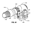
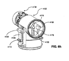
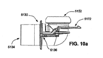
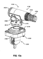
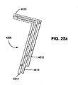
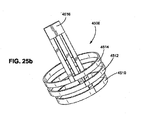
本技術の他の態様は、呼吸治療のための接続アセンブリに向けられる。接続アセンブリは、出口アセンブリであって、前記出口アセンブリが、出口ハウジングと、前記出口ハウジング上に位置される旋回ディスクとを含み、前記出口ハウジングが空洞と環状部分とを備える、出口アセンブリと、電気コネクタに接続する第1の端部と、呼吸治療システムの少なくとも1つの電気構成要素に接続する第2の端部とを有するケーブルであって、前記ケーブルが弛み部を有する、ケーブルとを備えてもよく、前記旋回ディスクは、第1の位置と第2の位置との間で前記出口ハウジングに対して回転でき、ケーブルの弛み部は、空洞から延在するとともに、旋回ディスクが第1の位置から第2の位置まで回転されるにつれて環状部分の周囲に巻き付く。 Another aspect of the present technology is directed to a connection assembly for respiratory treatment. An electrical outlet assembly, wherein the electrical outlet assembly includes an electrical outlet housing, a swivel disk positioned on the electrical outlet housing, the electrical outlet housing comprising a cavity and an annular portion; A cable having a first end connecting to the connector and a second end connecting to at least one electrical component of the respiratory treatment system, wherein the cable has a slack. The swivel disk may be rotatable relative to the outlet housing between a first position and a second position, wherein a slack in the cable extends from the cavity and the swivel disk is in the first position. Wrap around the annular portion as it is rotated from the second position to the second position.
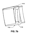
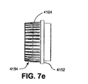
実施例において、(a)出口ハウジングに対する旋回ディスクの回転を制限するために、前記旋回ディスクがストッパ面の第1の対を含んでもよく、前記出口ハウジングがストッパ面の第2の対を含んでもよく、(b)ストッパ面のそれぞれの対は、出口ハウジングに対する旋回ディスクの回転を360°未満に制限するように配置されてもよく、(c)ストッパ面のそれぞれの対は、出口ハウジングに対する旋回ディスクの回転を180°を超えるように制限するべく配置されてもよく、(d)ストッパ面の第1の対は、ケーブルを受ける旋回ディスクの受け入れ開口の両側に該開口に隣接して位置されてもよく、(e)出口ハウジングが内壁を含んでもよく、ストッパ面の前記第2の対が内壁上に位置されてもよく、前記内壁が前記旋回ディスクを回転可能に受けるように構成されてもよく、(f)空洞は、少なくとも部分的に、出口ハウジングの内壁と外壁とによって画定されてもよく、(g)空洞を横切る出口ハウジングの内壁と外壁との間の距離が約2mm〜約5mmの範囲内であってもよく、(h)ケーブルがフレキシブル回路基板又はリボンケーブルを備えてもよく、
(i)ケーブルが略長方形断面を有してもよく、また、略長方形断面の主辺が旋回ディスクの回転軸線と平行に向けられてもよく、(j)旋回ディスクは、電気コネクタを受けるための電気コネクタ受け部を含んでもよく、また、電気コネクタが電気コネクタ受け部内でケーブルに電気的に接続可能であってもよく、(k)電気コネクタ受け部は、出口コネクタが出口アセンブリに接続されるときに電気コネクタを受けるための開口を含んでもよく、また、出口コネクタは、該出口コネクタが出口アセンブリに接続されるときに電気コネクタ受け部の開口を覆うように形成されてもよく、(l)出口コネクタは、電気コネクタ受け部の突出部に対応するように形成される凹部を電気コネクタの近位端側に含んでもよく、(m)出口ハウジングがリテーナを含んでもよく、前記リテーナは、旋回ディスクが第2の位置から第1の位置まで回転されるにつれて出口ハウジングの空洞内で弛み部を保持するように構成されてもよく、(n)出口コネクタは、旋回ディスク上に位置される少なくとも1つの対応する切り欠きを介して出口コネクタを旋回ディスクに対して解放可能に接続するための少なくとも1つの保持機能部を含んでもよく、
(o)出口コネクタが少なくとも1つのタブを含んでもよく、前記少なくとも1つの保持機能部のそれぞれが対応するアクチュエータを有する対応するタブ上に位置されてもよく、また、前記アクチュエータのそれぞれは、旋回ディスクの対応する切り欠きから前記保持機能部のそれぞれを解放するようになっていてもよく、(p)ガス送出チューブは、該ガス送出チューブの少なくとも一部に沿って配置される加熱要素を含んでもよく、前記加熱要素が電気コネクタに接続されてもよく、(q)出口コネクタは、ガス送出チューブを出口コネクタのチューブ接続領域に接続するためのグロメットを含んでもよく、(r)グロメットは、ガス送出チューブの対応するコイルを受けるためのネジを含んでもよく、(s)記グロメットが熱可塑性エラストマーから構成されてもよく、(t)グロメットは、成形中にグロメットを拘束するための少なくとも1つのキー溝を含んでもよく、(u)グロメットは、成形中に金型と係合するための少なくとも1つの径方向フランジを含んでもよく、(v)グロメットがグリップ部分を含んでもよく、(w)グリップ部分は、グロメットの周囲に径方向に配置される複数の隆起部及び凹部を含んでもよく、(x)出口コネクタがエルボーを備えてもよく、(y)エルボーが約90°の角度で曲げられてもよく、(z)出口コネクタが出口アセンブリに接続されるときに回転可能な電気的及び空気圧的な接続が形成されてもよく、
(aa)出口アセンブリは、出口コネクタに接続して該出口コネクタと空気圧シールを形成するためにテーパ状端部を有する空気流チューブを備えてもよく、(bb)旋回ディスクは、該旋回ディスクを出口ハウジングに回転可能に接続するために少なくとも1つのタングを含んでもよく、(cc)弛み部は、旋回ディスクの外周よりも短い所定の長さを備えてもよく、(dd)旋回ディスクが第1の位置にあるときに弛み部が空洞内に集まってもよく、(ee)旋回ディスクが第1の位置にあるときには、旋回ディスクが第2の位置にあるときよりも大きなケーブルの部分が空洞部内に収容されてもよく、(ff)接続アセンブリにより形成される電気的接続は、給電機能及び/又は信号送信機能を果たすために少なくとも1つの配線を備えてもよく、(gg)出口コネクタは、出口アセンブリに接続されるときに出口コネクタを空気流チューブ上に支持するために出口接続領域に少なくとも1つのリブを含んでもよく、(hh)接続アセンブリは、ガス送出チューブ部の端部に位置されてガス送出チューブ部を出口アセンブリに接続する出口コネクタを備えてもよく、前記出口コネクタが電気コネクタを含み、前記出口コネクタ及び前記旋回ディスクは、前記出口コネクタ及び前記旋回ディスクが一体で回転できるように接続可能であり、
(ii)環状部分は、少なくとも部分的に、出口ハウジングの前記内壁と外壁とによって画定されてもよく、(jj)空洞及び前記環状部分が内壁の両側にあってもよく、(kk)出口ハウジングが熱可塑性エラストマーから構成されてもよく、(ll)エルボーが0°〜120°の角度で曲げられてもよく、(mm)空気流チューブが取り外し可能であってもよく、(nn)出口コネクタがチューブ接続領域に受け部を含み、前記受け部は、受け部ネジ、受け部フランジ、及び、少なくとも1つの突起を備え、(oo)出口コネクタは、ガス送出チューブを受け部内に固定するためのクリップを備えてもよく、クリップは、クリップネジ、クリップフランジ、及び、少なくとも1つのタブを備え、また、少なくとも1つのタブのそれぞれは、クリップを受け部に固定するために少なくとも1つの突起のうちの対応する突起と係合するように構造化されてもよく、(pp)クリップネジ及び受け部ネジは、ガス送出チューブの対応するコイルを受けるように構造化されてもよく、及び/又は、(qq)クリップフランジ及び受け部フランジは、成形中に金型と係合するように構造化されてもよい。
In embodiments, (a) the swivel disk may include a first pair of stop surfaces and the outlet housing may include a second pair of stop surfaces to limit rotation of the swivel disk relative to the outlet housing. Well, (b) each pair of stop surfaces may be arranged to limit rotation of the swivel disk relative to the outlet housing to less than 360 °, and (c) each pair of stop surfaces may be pivoted relative to the outlet housing. May be arranged to limit the rotation of the disk to more than 180 °, and (d) a first pair of stop surfaces are positioned adjacent to and adjacent to the receiving opening of the pivoting disk for receiving the cable. (E) the outlet housing may include an inner wall, the second pair of stop surfaces may be located on the inner wall, the inner wall rotatably receiving the pivot disc. (F) the cavity may be defined, at least in part, by an inner wall and an outer wall of the outlet housing; and (g) a gap between the inner wall and the outer wall of the outlet housing traversing the cavity. The distance may be in the range of about 2 mm to about 5 mm, (h) the cable may comprise a flexible circuit board or a ribbon cable,
(I) the cable may have a substantially rectangular cross-section, and the major side of the substantially rectangular cross-section may be oriented parallel to the axis of rotation of the swivel disc; and (j) the swivel disc receives an electrical connector. And the electrical connector may be electrically connectable to a cable within the electrical connector receptacle, the electrical connector receptacle having an outlet connector connected to the outlet assembly. The outlet connector may include an opening for receiving the electrical connector when the outlet connector is connected to the outlet assembly, and the outlet connector may be formed to cover the opening of the electrical connector receiver when the outlet connector is connected to the outlet assembly. l) The outlet connector may include a recess formed on the proximal end of the electrical connector to correspond to the protrusion of the electrical connector receiver, and (m) the outlet housing Wherein the retainer may be configured to retain a slack within the cavity of the outlet housing as the pivot disk is rotated from the second position to the first position; The connector may include at least one retaining feature for releasably connecting the outlet connector to the pivot disc via at least one corresponding notch located on the pivot disc;
(O) the outlet connector may include at least one tab, each of the at least one retention feature may be located on a corresponding tab having a corresponding actuator, and each of the actuators may be pivoted (P) the gas delivery tube includes a heating element disposed along at least a portion of the gas delivery tube. The heating element may be connected to an electrical connector, the (q) outlet connector may include a grommet for connecting a gas delivery tube to a tube connection area of the outlet connector, and (r) the grommet may include: The grommet may include a screw for receiving the corresponding coil of the gas delivery tube, and the grommet may be a thermoplastic elastomer. (T) the grommet may include at least one keyway for restraining the grommet during molding, and (u) the grommet for engaging the mold during molding. The grommet may include at least one radial flange, the (g) grommet may include a grip portion, and the (w) grip portion may include a plurality of ridges and recesses radially disposed about the grommet. (X) the outlet connector may include an elbow, (y) the elbow may be bent at an angle of about 90 °, and (z) a rotatable electrical connector when the outlet connector is connected to the outlet assembly. And a pneumatic connection may be formed,
(Aa) the outlet assembly may include an airflow tube having a tapered end to connect to the outlet connector to form a pneumatic seal with the outlet connector; The at least one tongue may include at least one tongue for rotatably connecting to the outlet housing, the (cc) slack may have a predetermined length shorter than the outer circumference of the swivel disk, and The slacks may collect in the cavity when in the first position, and (ee) when the swivel disk is in the first position, a larger section of the cable than when the swivel disk is in the second position. (Ff) the electrical connection formed by the connection assembly may comprise at least one wiring to perform a power supply function and / or a signal transmission function, and (gg) an outlet connection. The connector may include at least one rib in the outlet connection area to support the outlet connector on the airflow tube when connected to the outlet assembly, wherein the (hh) connection assembly includes an end of the gas delivery tube portion. An outlet connector for connecting the gas delivery tube section to an outlet assembly, the outlet connector including an electrical connector, the outlet connector and the swivel disk being integral with the outlet connector and the swivel disk. It is connectable so that it can rotate,
(Ii) an annular portion may be defined, at least in part, by said inner and outer walls of an outlet housing; (jj) the cavity and said annular portion may be on opposite sides of the inner wall; May be composed of a thermoplastic elastomer, (ll) the elbow may be bent at an angle of 0 ° to 120 °, (mm) the airflow tube may be removable, and (nn) the outlet connector Includes a receiver in the tube connection area, the receiver including a receiver screw, a receiver flange, and at least one protrusion; and (oo) an outlet connector for securing the gas delivery tube in the receiver. The clip may include a clip screw, a clip flange, and at least one tab, and each of the at least one tab is for securing the clip to a receiver. The at least one protrusion may be structured to engage a corresponding one of the at least one protrusion, and the (pp) clip screw and the receiver screw are structured to receive a corresponding coil of the gas delivery tube. And / or (qq) the clip flange and the receiver flange may be structured to engage the mold during molding.
本技術の他の態様は、呼吸治療装置と共に使用するための空気回路を製造する方法に向けられる。方法は、チューブ接続領域を含む出口コネクタ下部構造体を成形するステップであって、前記チューブ接続領域の内部は、オリフィスが出口コネクタ下部構造体にチューブ接続領域の反対側で形成されるようにマンドレルの周囲に形成される、ステップと、螺旋加熱要素が配置されて成るガス送出チューブの第1の端部にグロメットを、ガス送出チューブの接続部がグロメットを貫通して延在するように螺合するステップと、ガス送出チューブの接続部を出口コネクタ下部構造体のチューブ接続領域に接続するステップと、出口コネクタ下部構造体のチューブ接続領域で螺旋加熱要素に電気コネクタを取り付けるステップと、少なくとも部分的にグロメットの周囲で金型をシールすることによって、出口コネクタ下部構造体上にわたって出口コネクタハウジングを成形するステップと、オリフィスを覆ってエンドキャップを取り付けるステップとを備えてもよい。 Another aspect of the present technology is directed to a method of manufacturing a pneumatic circuit for use with a respiratory treatment device. The method comprises the step of molding an outlet connector substructure including a tube connection region, wherein the interior of the tube connection region has a mandrel such that an orifice is formed in the outlet connector substructure on the opposite side of the tube connection region. Forming a grommet at a first end of the gas delivery tube, wherein the step includes a spiral heating element disposed therein, such that a connection of the gas delivery tube extends through the grommet. Connecting the gas delivery tube connection to the tube connection area of the outlet connector undercarriage; and attaching the electrical connector to the spiral heating element at the tube connection area of the outlet connector undercarriage; Sealing the mold around the grommet allows the outlet connector to extend over the outlet connector substructure. Forming the nectar housing and attaching an end cap over the orifice may be provided.
本技術の他の態様は、患者の睡眠呼吸障害の処置のための呼吸治療システムに向けられる。呼吸治療システムは、空気の流れを陽圧で患者に与えるための圧力発生器であって、ハウジングを備える圧力発生器と、ハウジングに位置される出口アセンブリであって、該出口アセンブリが出口ハウジングと前記出口ハウジングに位置される旋回ディスクとを備え、前記出口ハウジングが空洞を備え、前記出口アセンブリが、電気コネクタに接続する第1の端部と、呼吸治療システムの少なくとも1つの電気構成要素に接続する第2の端部とを有するケーブルを備え、前記ケーブルが弛み部を有する、出口アセンブリと、第1の端部で出口アセンブリに接続するとともに第2の端部で患者インタフェースに接続するように構成される空気回路であって、前記空気回路が、ガス送出チューブの第2の端部に位置されてガス送出チューブを出口アセンブリに接続する出口コネクタを備え、前記出口コネクタが前記電気コネクタを含む、空気回路とを備え、前記出口コネクタ及び前記旋回ディスクは、前記出口コネクタ及び前記旋回ディスクが一体で第1の位置と第2の位置との間を前記出口ハウジングに対して回転できるように接続可能であり、旋回ディスクが第1の位置にあるときには、旋回ディスクが前記第2の位置にあるときよりも大きなケーブルの部分が空洞部内に収容される。 Another aspect of the present technology is directed to a respiratory treatment system for treating sleep disordered breathing in a patient. The respiratory therapy system is a pressure generator for providing a flow of air to the patient at a positive pressure, the pressure generator comprising a housing, and an outlet assembly located on the housing, wherein the outlet assembly comprises an outlet housing. A swivel disk located in the outlet housing, the outlet housing comprising a cavity, the outlet assembly connecting to a first end for connection to an electrical connector, and to at least one electrical component of a respiratory treatment system. A cable having a second end, the cable having a slack, so as to connect to the outlet assembly at a first end and to a patient interface at a second end. An air circuit configured, said air circuit positioned at a second end of the gas delivery tube for outlet assembly of the gas delivery tube. An outlet circuit for connecting to the outlet connector, the outlet connector including the electrical connector, and a pneumatic circuit, wherein the outlet connector and the turning disk are integrated with the outlet connector and the turning disk in a first position and a second position. And the pivot housing is rotatably connectable to the outlet housing so that when the swivel disk is in the first position, a larger cable section than when the swivel disk is in the second position. It is housed in the cavity.
実施例において、(a)出口ハウジングに対する旋回ディスクの回転を制限するために、前記旋回ディスクがストッパ面の第1の対を含んでもよく、前記出口ハウジングがストッパ面の第2の対を含んでもよく、(b)ストッパ面のそれぞれの対は、出口ハウジングに対する旋回ディスクの回転を360°未満に制限するように配置されてもよく、(c)ストッパ面のそれぞれの対は、出口ハウジングに対する旋回ディスクの回転を180°を超えるように制限するべく配置されてもよく、(d)ストッパ面の第1の対は、ケーブルを受ける旋回ディスクの受け入れ開口の両側に該開口に隣接して位置されてもよく、(e)出口ハウジングが内壁を含んでもよく、ストッパ面の前記第2の対が内壁上に位置されてもよく、前記内壁が前記旋回ディスクを回転可能に受けるように構成されてもよく、(f)空洞は、少なくとも部分的に、出口ハウジングの内壁と外壁とによって画定されてもよく、(g)空洞を横切る出口ハウジングの内壁と外壁との間の距離が約2mm〜約5mmの範囲内であってもよく、(h)ケーブルがフレキシブルの回路基板又はリボンケーブルを備えてもよく、
(i)ケーブルが略長方形断面を有してもよく、また、略長方形断面の主辺が旋回ディスクの回転軸線と平行に向けられてもよく、(j)旋回ディスクは、電気コネクタを受けるための電気コネクタ受け部を含んでもよく、また、電気コネクタが電気コネクタ受け部内でケーブルに電気的に接続可能であってもよく、(k)電気コネクタ受け部は、出口コネクタが出口アセンブリに接続されるときに電気コネクタを受けるための開口を含んでもよく、また、出口コネクタは、該出口コネクタが出口アセンブリに接続されるときに電気コネクタ受け部の開口を覆うように形成されてもよく、(l)出口コネクタは、電気コネクタ受け部の突出部に対応するように形成される凹部を電気コネクタの近位端側に含んでもよく、(m)出口ハウジングがリテーナを含んでもよく、前記リテーナは、旋回ディスクが第2の位置から第1の位置まで回転されるにつれて出口ハウジングの空洞内で弛み部を保持するように構成されてもよく、(n)出口コネクタは、旋回ディスク上に位置される少なくとも1つの対応する切り欠きを介して出口コネクタを旋回ディスクに対して解放可能に接続するための少なくとも1つの保持機能部を含んでもよく、
(o)出口コネクタが少なくとも1つのタブを含んでもよく、前記少なくとも1つの保持機能部のそれぞれが対応するアクチュエータを有する対応するタブ上に位置されてもよく、また、前記アクチュエータのそれぞれは、旋回ディスクの対応する切り欠きから前記保持機能部のそれぞれを解放するようになっていてもよく、(p)ガス送出チューブは、該ガス送出チューブの少なくとも一部に沿って配置される加熱要素を含んでもよく、前記加熱要素が電気コネクタに接続されてもよく、(q)出口コネクタは、ガス送出チューブを出口コネクタのチューブ接続領域に接続するためのグロメットを含んでもよく、(r)グロメットは、ガス送出チューブの対応するコイルを受けるためのネジを含んでもよく、(s)記グロメットが熱可塑性エラストマーから構成されてもよく、(t)グロメットは、成形中にグロメットを拘束するための少なくとも1つのキー溝を含んでもよく、(u)グロメットは、成形中に金型と係合するための少なくとも1つの径方向フランジを含んでもよく、(v)グロメットがグリップ部分を含んでもよく、(w)グリップ部分は、グロメットの周囲に径方向に配置される複数の隆起部及び凹部を含んでもよく、(x)出口コネクタがエルボーを備えてもよく、(y)エルボーが約90°の角度で曲げられてもよく、(z)出口ハウジングが熱可塑性エラストマーから構成されてもよく、
(aa)出口コネクタが出口アセンブリに接続されるときに回転可能な電気的及び空気圧的な接続が形成されてもよく、(bb)出口アセンブリは、出口コネクタに接続して該出口コネクタと空気圧シールを形成するためにテーパ状端部を有する空気流チューブを備えてもよく、(cc)旋回ディスクは、該旋回ディスクを出口ハウジングに回転可能に接続するために少なくとも1つのタングを含んでもよく、(dd)弛み部は、旋回ディスクの外周よりも短い所定の長さを備えてもよく、(ee)旋回ディスクが第1の位置にあるときに弛み部が空洞内に集まってもよく、(ff)ケーブルの弛み部は、空洞から延在するとともに、旋回ディスクが第1の位置から第2の位置まで回転されるにつれて環状部分の周囲に巻き付き、(gg)接続アセンブリにより形成される電気的接続は、給電機能及び/又は信号送信機能を果たすために少なくとも1つの配線を備えてもよく、(hh)出口コネクタは、出口アセンブリに接続されるときに出口コネクタを空気流チューブ上に支持するために出口接続領域に少なくとも1つのリブを含んでもよく、(ii)呼吸治療システムは、空気の流れを加湿するための加湿器を備えてもよく、(jj)出口ハウジングは、旋回ディスクが第2の位置にあるときにケーブルを受けるように構成される環状部分を備えてもよく、
(kk)エルボーが0°〜120°の角度で曲げられてもよく、(ll)空気流チューブが取り外し可能であってもよく、(mm)出口コネクタがチューブ接続領域に受け部を含み、前記受け部は、受け部ネジ、受け部フランジ、及び、少なくとも1つの突起を備え、(nn)出口コネクタは、ガス送出チューブを受け部内に固定するためのクリップを備えてもよく、クリップは、クリップネジ、クリップフランジ、及び、少なくとも1つのタブを備え、また、少なくとも1つのタブのそれぞれは、クリップを受け部に固定するために少なくとも1つの突起のうちの対応する突起と係合するように構造化されてもよく、(oo)クリップネジ及び受け部ネジは、ガス送出チューブの対応するコイルを受けるように構造化されてもよく、及び/又は、(pp)クリップフランジ及び受け部フランジは、成形中に金型と係合するように構造化されてもよい。
In embodiments, (a) the swivel disk may include a first pair of stop surfaces and the outlet housing may include a second pair of stop surfaces to limit rotation of the swivel disk relative to the outlet housing. Well, (b) each pair of stop surfaces may be arranged to limit rotation of the swivel disk relative to the outlet housing to less than 360 °, and (c) each pair of stop surfaces may be pivoted relative to the outlet housing. May be arranged to limit the rotation of the disk to more than 180 °, and (d) a first pair of stop surfaces are positioned adjacent to and adjacent to the receiving opening of the pivoting disk for receiving the cable. (E) the outlet housing may include an inner wall, the second pair of stop surfaces may be located on the inner wall, the inner wall rotatably receiving the pivot disc. (F) the cavity may be defined, at least in part, by an inner wall and an outer wall of the outlet housing; and (g) a gap between the inner wall and the outer wall of the outlet housing traversing the cavity. The distance may be in the range of about 2 mm to about 5 mm, (h) the cable may comprise a flexible circuit board or a ribbon cable,
(I) the cable may have a substantially rectangular cross-section, and the major side of the substantially rectangular cross-section may be oriented parallel to the axis of rotation of the swivel disc; and (j) the swivel disc receives an electrical connector. And the electrical connector may be electrically connectable to a cable within the electrical connector receptacle, the electrical connector receptacle having an outlet connector connected to the outlet assembly. The outlet connector may include an opening for receiving the electrical connector when the outlet connector is connected to the outlet assembly, and the outlet connector may be formed to cover the opening of the electrical connector receiver when the outlet connector is connected to the outlet assembly. l) The outlet connector may include a recess formed on the proximal end of the electrical connector to correspond to the protrusion of the electrical connector receiver, and (m) the outlet housing Wherein the retainer may be configured to retain a slack within the cavity of the outlet housing as the pivot disk is rotated from the second position to the first position; The connector may include at least one retaining feature for releasably connecting the outlet connector to the pivot disc via at least one corresponding notch located on the pivot disc;
(O) the outlet connector may include at least one tab, each of the at least one retention feature may be located on a corresponding tab having a corresponding actuator, and each of the actuators may be pivoted (P) the gas delivery tube includes a heating element disposed along at least a portion of the gas delivery tube. The heating element may be connected to an electrical connector, the (q) outlet connector may include a grommet for connecting a gas delivery tube to a tube connection area of the outlet connector, and (r) the grommet may include: The grommet may include a screw for receiving the corresponding coil of the gas delivery tube, and the grommet may be a thermoplastic elastomer. (T) the grommet may include at least one keyway for restraining the grommet during molding, and (u) the grommet for engaging the mold during molding. The grommet may include at least one radial flange, the (g) grommet may include a grip portion, and the (w) grip portion may include a plurality of ridges and recesses radially disposed about the grommet. (X) the outlet connector may comprise an elbow, (y) the elbow may be bent at an angle of about 90 °, (z) the outlet housing may be comprised of a thermoplastic elastomer,
(Aa) a rotatable electrical and pneumatic connection may be formed when the outlet connector is connected to the outlet assembly; and (bb) the outlet assembly connects to the outlet connector and the pneumatic seal. May comprise an airflow tube having a tapered end to form a (cc) swivel disk, which may include at least one tongue to rotatably connect the swivel disk to an outlet housing; (Dd) the slack may have a predetermined length shorter than the outer circumference of the swivel disk, (ee) the slack may collect in the cavity when the swivel disk is in the first position, ff) A slack in the cable extends from the cavity and wraps around the annular portion as the swivel disk is rotated from the first position to the second position, and is formed by the (gg) connection assembly. The electrical connection may include at least one wire to perform a power supply function and / or a signal transmission function, and (hh) the outlet connector includes an outlet connector on the airflow tube when connected to the outlet assembly. (Ii) the respiratory treatment system may comprise a humidifier for humidifying the air flow, and (jj) the outlet housing An annular portion configured to receive the cable when the disk is in the second position,
(Kk) the elbow may be bent at an angle of 0 ° to 120 °, (ll) the airflow tube may be removable, (mm) the outlet connector includes a receiver in the tube connection area, The receiver may include a receiver screw, a receiver flange, and at least one protrusion, and the (nn) outlet connector may include a clip for securing the gas delivery tube in the receiver, wherein the clip includes a clip. A screw, a clip flange, and at least one tab, wherein each of the at least one tab is configured to engage a corresponding one of the at least one protrusion to secure the clip to the receiver. (Oo) clip screws and receiving screws may be structured to receive the corresponding coils of the gas delivery tube, and / or (pp) clip flanks. And receiving flange may be structured so as to mold engages during the molding.
本技術の他の態様は、呼吸治療のための接続アセンブリに向けられる。接続アセンブリは、ハウジングと、ハウジングに位置されるとともに出口チューブを含む出口アセンブリと、ガス送出チューブに空気圧的に接続するようになっている第1の端部と、出口アセンブリに回転可能に接続して出口チューブと空気圧的接続を形成するようになっている第2の端部とを有する出口コネクタと、複数の第1の電気コネクタと、複数の第1の電気コネクタのうちの1つとに電気的に接続するようになっている第2の電気コネクタとを備えてもよく、出口アセンブリ及び出口コネクタは、空気圧的接続及び電気的接続の両方を形成するために複数の所定の別個の位置で取り外し可能に接続できる。 Another aspect of the present technology is directed to a connection assembly for respiratory treatment. The connection assembly includes a housing, an outlet assembly located in the housing and including an outlet tube, a first end adapted to pneumatically connect to the gas delivery tube, and a rotatable connection to the outlet assembly. An outlet connector having a second end adapted to form a pneumatic connection with the outlet tube; a plurality of first electrical connectors; and one of the plurality of first electrical connectors. A second electrical connector adapted to electrically connect the outlet assembly and the outlet connector at a plurality of predetermined discrete locations to form both a pneumatic connection and an electrical connection. Can be detachably connected.
実施例において、(a)複数の第1の電気コネクタの量は、複数の所定の別個の位置の量に等しくてもよく、(b)出口アセンブリが複数の第1の電気コネクタを備えてもよく、出口コネクタが第2の電気コネクタを備えてもよく、(c)出口アセンブリは、複数の第1の電気コネクタを呼吸治療システムの少なくとも1つの電子構成要素に電気的に接続するために少なくとも1つのケーブルを含んでもよく、(d)出口アセンブリが第2の電気コネクタを備えてもよく、出口コネクタが複数の第1の電気コネクタを備えてもよく、(e)接続アセンブリは、第2の電気コネクタに接続されない複数の第1の電気コネクタのうちの少なくとも1つを覆うように構成される少なくとも1つのダミーコネクタを備えてもよく、(f)少なくとも1つのダミーコネクタの量は、複数の第1の電気コネクタの量よりも1つ少なくてもよく、(g)出口コネクタがエルボーを備えてもよく、(h)エルボーが約90°の角度で曲げられてもよく、(i)出口アセンブリは、出口コネクタの第2の端部を受けるための凹部を含んでもよく、凹部及び出口コネクタの第2の端部がほぼ対応して形成されてもよく、(j)エルボーが0°〜120°の角度で曲げられてもよく、及び/又は、(k)接続アセンブリによって形成される電気的接続は、給電機能及び/又は信号送信機能を果たすための少なくとも1つの配線を備えてもよい。 In embodiments, the amount of (a) the plurality of first electrical connectors may be equal to the amount of the plurality of predetermined discrete locations, and (b) the outlet assembly comprises the plurality of first electrical connectors. Frequently, the outlet connector may comprise a second electrical connector, and (c) the outlet assembly at least for electrically connecting the plurality of first electrical connectors to at least one electronic component of the respiratory treatment system. The cable may include one cable, (d) the outlet assembly may include a second electrical connector, the outlet connector may include a plurality of first electrical connectors, and (e) the connection assembly may include a second electrical connector. And at least one dummy connector configured to cover at least one of the plurality of first electrical connectors not connected to the electrical connector of (f) wherein the amount of the at least one dummy connector is: One less than the amount of the plurality of first electrical connectors, (g) the outlet connector may include an elbow, (h) the elbow may be bent at an angle of about 90 °, (i ) The outlet assembly may include a recess for receiving the second end of the outlet connector, the recess and the second end of the outlet connector may be substantially correspondingly formed, and (j) the elbow may be zero. And / or (k) the electrical connection formed by the connection assembly comprises at least one wire for performing a power supply function and / or a signal transmission function. Is also good.
本技術の他の態様は、呼吸治療装置と共に使用するための空気回路を製造する方法に向けられる。方法は、出口コネクタ下部構造体を成形するステップであって記出口コネクタ下部構造体がチューブ接続領域に受け部及び受け部ネジを含み、前記出口コネクタ下部構造体の内部は、オリフィスが出口コネクタ下部構造体にチューブ接続領域の反対側で形成されるようにマンドレルの周囲に形成される、ステップと、螺旋加熱要素が配置されて成るガス送出チューブの第1の端部を、ガス送出チューブの接続部が受け部を貫通して延在するように受け部ネジに螺合するステップと、クリップをガス送出チューブの接続部が受け部とクリップとにより実質的に取り囲まれるようにガス送出チューブの接続部の周囲に固定することによってガス送出チューブの接続部を出口コネクタ下部構造体のチューブ接続領域に接続するステップと、出口コネクタ下部構造体のチューブ接続領域で螺旋加熱要素に電気コネクタを取り付けるステップと、少なくとも部分的にチューブ接続領域の周囲で金型をシールすることによって、出口コネクタ下部構造体上にわたって出口コネクタハウジングを成形するステップと、オリフィスを覆ってエンドキャップを取り付けるステップとを備えてもよい。 Another aspect of the present technology is directed to a method of manufacturing a pneumatic circuit for use with a respiratory treatment device. The method comprises the step of forming an outlet connector substructure, the outlet connector substructure including a receiving portion and a receiving screw in a tube connection area, wherein the interior of the outlet connector substructure has an orifice having an outlet connector lower portion. A step formed around the mandrel as formed on the opposite side of the tube connection area to the structure, and connecting the first end of the gas delivery tube where the helical heating element is located to the connection of the gas delivery tube. Screwing the clip into the receptacle screw such that the section extends through the receptacle, and connecting the gas delivery tube such that the connection of the gas delivery tube is substantially surrounded by the receptacle and the clip. Connecting the connection of the gas delivery tube to the tube connection area of the outlet connector undercarriage by securing around the periphery of the outlet connector; Forming an outlet connector housing over the outlet connector substructure by attaching an electrical connector to the helical heating element at the tube connection region of the substructure and at least partially sealing the mold around the tube connection region And attaching an end cap over the orifice.
実施例において、(a)クリップが受け部とは別個の構成要素であってもよく、クリップが一対のタブを備え、受け部が一対の突起を備え、また、クリップを固定するステップは、一対のタブのそれぞれを一対の突起のうちの対応する突起にスナップ係合させることを含んでもよく、(b)クリップと受け部とが一体を成してもよく、クリップがヒンジによって受け部に連結され、クリップがタブを備え、受け部が突起を備え、クリップを固定するステップは、タブを突起にスナップ係合させることを含んでもよい。 In an embodiment, (a) the clip may be a separate component from the receiving portion, the clip includes a pair of tabs, the receiving portion includes a pair of protrusions, and the step of fixing the clip includes a pair of tabs. Snap-engaging each of the tabs with a corresponding one of the pair of protrusions, and (b) the clip and the receiving part may be integral, and the clip is connected to the receiving part by a hinge. Wherein the clip comprises a tab and the receptacle comprises a projection, and the step of securing the clip may comprise snap-engaging the tab with the projection.
本技術の他の態様は、睡眠呼吸障害の処置のために持続的気道陽圧を患者に供給するための出口コネクタアセンブリに向けられる。出口コネクタアセンブリは、チューブ接続領域及び出口接続領域を有する本体と、キャップであって、キャップ及び本体がチューブ接続領域と出口接続領域との間に空気流路を少なくとも部分的に画定するように本体に取り付くように構造化されたキャップと、本体に成形されるとともに、チューブ接続領域と出口接続領域との間に電気的接続を形成するように構成される電気接点アセンブリとを備えてもよい。 Another aspect of the present technology is directed to an outlet connector assembly for providing continuous positive airway pressure to a patient for treatment of sleep-disordered breathing. An outlet connector assembly includes a body having a tube connection area and an outlet connection area, and a cap, wherein the cap and the body at least partially define an air flow path between the tube connection area and the outlet connection area. And an electrical contact assembly molded to the body and configured to form an electrical connection between the tube connection area and the outlet connection area.
実施例において、(a)キャップ及び本体によって少なくとも部分的に画定される空気流路が湾曲形状を有してもよく、空気流路が略均一な断面を有してもよく、(b)空気流路の湾曲形状の半径が空気流路の直径の1〜3倍であってもよく、(c)空気流路の湾曲形状の内半径及び外半径がほぼ共通の円弧中心を共有してもよく、(d)チューブ接続領域が肩部及び接点凹部を備えてもよく、(e)電気接点アセンブリが接点凹部内に位置される接点を備えてもよく、接点が出口接続領域の全周にわたって延在され、(f)キャップがタブ及び突起を備えてもよく、本体が切り欠き及び戻り止めを備えてもよく、キャップを本体に取り付けるためにタブが切り欠きと係合してもよいとともに突起が戻り止めと係合してもよく、(g)チューブ接続領域は、ガス送出チューブの螺旋コイルを受けるように形成されるネジを備えてもよく、及び/又は(h)出口コネクタアセンブリは、空気流路を空気圧的にシールするために本体及びキャップに対してオーバーモールドされるハウジングを備えてもよい。 In embodiments, (a) the air flow path at least partially defined by the cap and the body may have a curved shape, the air flow path may have a substantially uniform cross section, and (b) air The radius of the curved shape of the flow path may be 1 to 3 times the diameter of the air flow path, and (c) the inner and outer radii of the curved shape of the air flow path share a substantially common arc center. Well, (d) the tube connection area may comprise a shoulder and a contact recess, (e) the electrical contact assembly may comprise a contact located in the contact recess, wherein the contact extends around the entire circumference of the outlet connection area. Extended, (f) the cap may include tabs and protrusions, the body may include notches and detents, and the tabs may engage with the notches to attach the cap to the body. The projection may engage the detent, and (g) the tube connection area And / or (h) the outlet connector assembly may be overmolded with respect to the body and cap to pneumatically seal the air flow path. May be provided.
無論、実施例/態様の一部は、本技術の下位実施例/下位態様を形成してもよい。また、下位実施例/下位態様及び/又は実施形態/態様のうちの様々なものは、様々な方法で組み合わされてもよく、また、本技術の更なる実施例/態様又は下位実施形態/下位態様を構成してもよい。 Of course, some of the embodiments / aspects may form a sub-example / sub-aspect of the present technology. Also, various ones of the sub-examples / sub-aspects and / or embodiments / aspects may be combined in various ways, and further examples / aspects or sub-embodiments / sub-features of the present technology. An embodiment may be configured.
本技術の他の特徴は、以下の詳細な説明、要約、図面、及び、特許請求の範囲に含まれる情報を考慮することにより明らかである。 Other features of the technology will be apparent from consideration of the following detailed description, abstract, drawings, and information contained in the claims.
5(D)図面の幾つかの図の簡単な説明
本技術は、添付図面の図に一例として示されており、限定的に示されていない。図中、同様の参照数字は同様の要素を示す。
5 (D) Brief Description of Several Figures of the Drawings The present technology is illustrated by way of example and not by way of limitation in the figures of the accompanying drawings. In the figures, like reference numerals indicate like elements.
5.1治療システム
6(E) 本技術の実施例の詳細な説明
本技術を更に詳しく説明する前に、本技術が本明細書中に記載される様々であってもよい特定の実施例に限定されないことが理解されるべきである。また、この開示において使用される用語は、本明細書中で論じられる特定の実施例を説明するという目的のためにすぎず、限定しようとするものでないことも理解されるべきである。
6 (E) Detailed description of embodiments of the present technology Before describing the present technology in further detail, it is understood that the present technology is not limited to the particular embodiments which may be varied as described herein. It should be. It should also be understood that the terms used in this disclosure are for the purpose of describing the particular embodiments discussed herein, and are not intended to be limiting.
以下の説明は、1つ以上の共通の特性及び/又は特徴を共有し得る様々な実施例に関連して与えられる。任意の1つの実施例の1つ以上の特徴が他の1つの実施例又は他の複数の実施例のうちの1つ以上の特徴と組み合わされてもよいことが理解されるべきである。また、任意の実施例における任意の単一の特徴又は特徴の組み合わせが更なる実施例を構成してもよい。 The following description is provided in connection with various embodiments that may share one or more common characteristics and / or features. It is to be understood that one or more features of any one embodiment may be combined with one or more features of one or more other embodiments. Also, any single feature or combination of features in any embodiment may constitute a further embodiment.
6.1治療システム
1つの形態において、本技術は、呼吸器疾患を処置するための呼吸治療システムを備える。呼吸治療システムは、空気などの呼吸用ガスの流れを患者インタフェース3000に通じる空気回路4100を介して患者1000へ供給するためのRPT装置4000を備えてもよい。幾つかの形態において、呼吸治療システムは、空気の流れを周囲環境に対して加湿するように構成される加湿器5000を更に備えてもよい。
6.1 Treatment system
In one aspect, the present technology includes a respiratory treatment system for treating a respiratory disease. The respiratory treatment system may include an
6.2 治療
1つの形態において、本技術は、患者1000の気道の入口に陽圧を印加するステップを備える呼吸器疾患を処置するための方法を備える。
6.2 Treatment
In one form, the present technology includes a method for treating a respiratory disease comprising applying a positive pressure to the entrance of an airway of a
1つの形態において、本技術は、鼻連続陽性気道圧を患者に印加することによって患者の閉塞性睡眠時無呼吸を処置する方法を備える。 In one aspect, the present technology comprises a method of treating obstructive sleep apnea in a patient by applying continuous nasal positive airway pressure to the patient.
本技術の特定の例において、陽圧の所定量の空気は、一方又は両方の鼻孔を介して患者の鼻通路へ供給される。 In certain examples of the present technology, a predetermined amount of air at a positive pressure is supplied to a patient's nasal passage through one or both nostrils.
本技術の特定の例では、口呼吸が制限される、抑制される、或いは、防止される。 In certain examples of the present technology, mouth breathing is limited, suppressed, or prevented.
6.3 患者インタフェース3000
本技術の1つの態様に係る非侵襲的な患者インタフェース3000は、以下の機能的態様、すなわち、シール形成構造体3100、プレナムチャンバ3200、位置決め安定化構造体3300、及び、空気回路4100への接続のための接続ポート3600を備える。例えば、これについては図2cを参照されたい。幾つかの形態では、機能的態様が1つ以上の物理的な構成要素によって与えられてもよい。幾つかの形態では、1つの物理的構成要素が1つ以上の機能的態様を与えてもよい。使用時、シール形成構造体は、陽圧の空気の気道への供給を容易にするために患者の気道への入口を取り囲むように配置される。
6.3
The
6.3.1 シール形成構造体
本技術の1つの形態において、シール形成構造体3100は、シール形成面を与えるとともに、クッション機能を更に与えてもよい。
6.3.1 Seal-forming structure In one form of the present technology, the seal-forming
本技術に係るシール形成構造体は、シリコンなどの柔軟な、可撓性のある、弾性材料から構成されてもよい。 The seal forming structure according to the present technology may be made of a flexible, flexible, elastic material such as silicon.
1つの形態では、シール形成構造体がシールフランジと支持フランジとを備える。シールフランジは、プレナムチャンバの外周にわたって延在する約1mm未満、例えば約0.25mm〜約0.45mmの厚さを有する比較的薄い部材を備えてもよい。支持フランジは、シールフランジよりも相対的に厚くてもよい。支持フランジは、シールフランジとプレナムチャンバの周縁との間に配置され、外周の少なくとも一部の経路にわたって延在する。支持フランジは、スプリング状要素であり或いはスプリング状要素を含み、使用時にシールフランジを座屈しないように支持するべく機能する。使用時、シールフランジは、該シールフランジを顔面との緊密なシール係合状態へと付勢するべくシールフランジの下面に作用するプレナムチャンバ内のシステム圧力に容易に応答し得る。 In one form, the seal-forming structure includes a seal flange and a support flange. The seal flange may include a relatively thin member having a thickness of less than about 1 mm, e.g., about 0.25 mm to about 0.45 mm, extending around the perimeter of the plenum chamber. The support flange may be relatively thicker than the seal flange. The support flange is located between the seal flange and the periphery of the plenum chamber and extends over at least a portion of a path of the outer periphery. The support flange is or includes a spring-like element and functions to support the seal flange from buckling during use. In use, the seal flange can readily respond to system pressure in the plenum chamber acting on the underside of the seal flange to urge the seal flange into tight sealing engagement with the face.
他の形態において、非侵襲的な患者インタフェース3000のシール形成部は、一対の鼻パフ又は一対の鼻枕を備え、それぞれの鼻パフ又は鼻枕は、患者の鼻のそれぞれの鼻孔とのシールを形成するように構成されて配置される。
In another form, the seal forming portion of the
本技術の一態様に係る鼻枕は、その少なくとも一部が患者の鼻の下面でシールを形成する円錐台と、柄部と、円錐台の下面にあって円錐台を柄部に接続する可撓性領域とを含む。また、本技術の鼻枕が接続される構造体は、柄部の基部に隣接する可撓性領域を含む。可撓性領域は、円錐台と鼻枕が接続される構造体との相対動作−変位及び傾斜の両方−に順応するユニバーサルジョイント構造を促進するように協調して作用し得る。例えば、円錐台は、柄部が接続される構造体へ向けて軸方向に移動されてもよい。 A nasal pillow according to one aspect of the present technology may have a truncated cone, at least a portion of which forms a seal with the lower surface of a patient's nose, a stem, and a truncated cone connected to the stem under the truncated cone. And a flexible region. Also, the structure to which the nasal pillow of the present technology is connected includes a flexible region adjacent to the base of the handle. The flexible regions may work in concert to promote a universal joint structure that accommodates the relative movement of the truncated cone and the structure to which the nasal pillow is connected-both displacement and tilt. For example, the truncated cone may be moved axially toward the structure to which the handle is connected.
1つの形態において、非侵襲的な患者インタフェース3000は、使用時に患者の顔面の上唇領域(すなわち、唇上部)でシールを形成するシール形成部を備える。
In one form, the
1つの形態において、非侵襲的な患者インタフェース3000は、使用時に患者の顔面の顎領域でシールを形成するシール形成部を備える。
In one form, the
6.3.2 プレナムチャンバ
プレナムチャンバ3200は、使用時にシールが生じる領域で平均的な人の顔の表面輪郭に対して相補的であるように形成される外周を有してもよい。使用時、プレナムチャンバの周縁は、顔の隣接する表面に近接して位置される。顔との実際の接触はシール形成構造体によってもたらされる。シール形成構造体は、使用時に、プレナムチャンバの全周にわたって延在してもよい。
6.3.2 Plenum
6.3.3 位置決め安定化構造体
本技術の患者インタフェース3000のシール形成部は、使用時に位置決め安定化構造体3300、例えばヘッドギアシステム又はストラップによってシール位置に保持されてもよい。
6.3.3 Positioning and Stabilizing Structure The seal formation of the
6.3.4 ベント
1つの形態において、患者インタフェース3000は、吐き出される二酸化炭素の流出を可能にするように構成されて配置されるベント3400を含んでもよい。
6.3.4 Vent
In one form, the
本技術に係るベント3400の1つの形態は、複数の穴、例えば約20〜約80個の穴、又は、約40〜約60個の穴、又は、約45〜約55個の穴を備える。
One form of
ベント3400がプレナムチャンバ3200に位置されてもよい。或いは、ベントは、デカップリング構造体、例えばスイベル又はボールアンドソケットに位置されてもよい。
A
6.3.5他の患者インタフェース構成要素
患者インタフェース3000は、以下の更なる構成要素のうちの1つ以上を含んでもよい。
(i)患者インタフェースを顔面上に支持するのを助ける前頭支持体3700;
(ii)患者1000が必要に応じて新鮮な空気を患者インタフェース3000内に受けることができるようにするための窒息防止弁;及び
(iii)プレナムチャンバ内の容積へのアクセスを可能にするための1つ以上のポート(例えば、接続ポート3600)。1つの形態では、これにより、医師が酸素補給を行なうことができる。1つの形態では、これにより、プレナムチャンバ内のガスの特性、例えば圧力の直接的な測定を行なうことができる。
6.3.5 Other Patient Interface Components The
(i)
(ii) an anti-asphyxia valve to allow the
(iii) one or more ports to allow access to the volume in the plenum chamber (eg, connection port 3600). In one form, this allows the physician to provide supplemental oxygen. In one form, this allows for a direct measurement of the properties of the gas in the plenum chamber, such as pressure.
6.4 RPT装置4000
本技術の1つの態様に係るRPT装置4000(図3a参照)は、機械的な空気圧式の構成要素4300と電気構成要素4200とを備えるとともに、1つ以上のアルゴリズムを実行するようにプログラミングされる。RPT装置は外部ハウジング4010を有してもよく、外部ハウジング4010は、2つの部分を成して、すなわち、上部4012と下部4014とを成して形成される。また、外部ハウジング4010が1つ以上のパネル4015を含んでもよい。RPT装置4000は、RPT装置4000の1つ以上の内部構成要素を支持する筐体4016を備えてもよい。1つの形態では、空気圧ブロック4020が筐体4016によって支持され或いは筐体4016の一部として形成される。RPT装置4000がハンドル4018を含んでもよい。一体型加湿器5000を含むRPT装置4000の他の例が図3b〜図3dに示される。
6.4
An RPT device 4000 (see FIG. 3a) according to one aspect of the present technology includes a mechanical pneumatic component 4300 and an
RPT装置4000の空気圧経路(例えば図3eに示される)は、入口空気フィルタ4312と、入口マフラ4322と、陽圧の空気を供給できる制御可能な圧力装置4340(例えば、ブロワ4342)と、出口マフラ4324とを備えてもよい。1つ以上の圧力センサ及び流量トランスデューサが空気圧経路中に含まれてもよい。
The pneumatic path of the RPT device 4000 (eg, shown in FIG. 3e) includes an
空気圧ブロック4020は、制御可能な圧力装置4340(例えばブロワ4342)を少なくとも収容する。空気圧ブロックは、外部ハウジング4010内に位置される空気圧経路の一部を構成してもよい。1つの形態において、筐体4016は、図3aに示されるように空気圧ブロック4020の一部を形成してもよい。他の形態において、筐体4016は、図3bに示されるように空気圧ブロック4020をその一部を形成することなく支持してもよい。
RAP装置4000は、電源4210と、1つ以上の入力装置4220と、中央コントローラ4230と、治療装置コントローラ4240と、圧力装置と、1つ以上の保護回路と、メモリと、トランスデューサ4270と、データ通信インタフェースと、1つ以上の出力装置とを有してもよい。電気構成要素4200が単一のプリント回路基板アセンブリ(PCBA)4202上に装着されてもよい。別の形態では、RPT装置4000が複数のPCBA4202を含んでもよい。
The
RPT装置4000の中央コントローラは、前処理モジュール、治療エンジンモジュール、圧力制御モジュール、及び、更なる故障状態モジュールを含む1つ以上のアルゴリズムモジュールを実行するようにプログラミングされてもよい。
The central controller of the
6.4.1 RPT機械的構成要素及び空気圧式構成要素4300
6.4.1.1 空気フィルタ4310
本技術の1つの形態に係るRPT装置は、1つの空気フィルタ4310又は複数の空気フィルタ4310を含んでもよい。
6.4.1 RPT mechanical and pneumatic components 4300
6.4.1.1
The RPT device according to one embodiment of the present technology may include one
1つの形態では、入口空気フィルタ4312がブロワ4342の上流側の空気圧経路の冒頭に位置される。図3e参照
In one form, an
1つの形態では、出口空気フィルタ4314、例えば抗菌フィルタが空気圧ブロック4020の出口と患者インタフェース3000との間に位置される。図3e参照
In one form, an outlet air filter 4314, eg, an antimicrobial filter, is located between the outlet of the
6.4.1.2 マフラ4320
本技術の1つの形態では、ブロワ4342の上流側の空気圧経路中に入口マフラ4322が位置される。図3e参照
6.4.1.2
In one form of the present technology, an inlet muffler 4322 is located in a pneumatic path upstream of the
本技術の1つの形態では、ブロワ4342と患者インタフェース3000の間の空気圧経路中に出口マフラ4324が位置される。図3e参照
In one form of the present technology, an exit muffler 4324 is located in the pneumatic path between the
6.4.1.3 圧力装置4340
本技術の一形態では、陽圧の空気の流れを生み出すための圧力装置4340(圧力発生器とも称される)が制御可能なブロワ4342である。例えば、ブロワは、1つ以上のインペラが渦巻きを成して収容されるブラシレスDCモータ4344を含んでもよい。ブロワは、約4cmH2O〜約20cmH2Oの範囲内、又は、他の形態では最大で約30cmH2Oの陽圧の例えば約120リットル/分の所定量の空気を送出することができてもよい。
6.4.1.3
In one form of the present technology, a pressure device 4340 (also referred to as a pressure generator) for creating a positive pressure air flow is a
圧力装置4340は治療装置コントローラ4240の制御下にある。
The
6.4.1.4 トランスデューサ4270
1つ以上のトランスデューサ4270は、空気圧経路中の1つ以上の所定のポイントで空気の特性又は外気の特性を測定するように構成されて配置されてもよい。
6.4.1.4
One or
本技術の1つの形態において、1つ以上のトランスデューサ4270は、圧力装置4340の下流側及び空気回路4100の上流側に位置される。本技術の1つの形態において、1つ以上のトランスデューサ4270は、圧力装置4340の上流側に位置される。
In one form of the present technology, one or
本技術の1つの形態において、1つ以上のトランスデューサ4270は患者インタフェース3000に近接して位置される。
In one form of the present technology, one or
6.4.1.5 逆流防止弁4360
本技術の1つの形態では、加湿器5000と空気圧ブロック4020との間に逆流防止弁が位置される。逆流防止弁は、水が加湿器5000よりも上流側へ、例えばモータ4344へ流れる危険を減らすように構成されて配置される。
6.4.1.5
In one form of the present technology, a non-return valve is located between
6.4.1.6 空気回路4100
本技術の一態様に係る空気回路4100は、空気圧ブロック4020と患者インタフェース3000との間での空気又は呼吸用ガスの流れを可能にするように構成されて配置される。
6.4.1.6
The
6.4.1.7 酸素送出4380
本技術の1つの形態では、補給酸素4380が空気圧経路中の1つのポイントへ送出される。
6.4.1.7
In one form of the present technology,
本技術の1つの形態では、補給酸素4380が空気圧ブロック4020の上流側に送出される。
In one form of the present technology,
本技術の1つの形態では、補給酸素4380が空気回路4100へ送出される。
In one form of the present technology,
本技術の1つの形態では、補給酸素4380が患者インタフェース3000へ送出される。
In one form of the present technology,
6.4.2 RPT装置電気構成要素4200
6.4.2.1 電源4210
電源4210ハンドル、基本的なRPT装置4000の他の構成要素、すなわち、入力装置4220、中央コントローラ4230、圧力装置4340、及び、出力装置4290(図3f参照)へ電力を供給する。
6.4.2 RPT device
6.4.2.1
The
本技術の1つの形態において、電源4210は、RPT装置4000の外部ハウジング4010の内部にある。本技術の1つの形態において、電源4210は、RPT装置4000の外部ハウジング4010の外部にある。
In one form of the present technology, the
6.4.2.2 入力装置4220
入力装置4220は、人がRPT装置4000と情報をやりとりできるようにするためにボタン、スイッチ、又は、ダイヤルを備える。ボタン、スイッチ、又は、ダイヤルは、物理的な装置であってもよく、或いは、タッチスクリーンを介してアクセスできるソフトウェア装置であってもよい。ボタン、スイッチ、又は、ダイヤルは、1つの形態では、外部ハウジング4010に物理的に接続されてもよく、或いは、他の形態では、中央コントローラに電気的に接続している受信器と無線通信状態にあってもよい。
6.4.2.2
1つの形態において、入力装置4220は、人が値及び/又はメニューオプションを選択できるようにするべく構成されて配置されてもよい。
In one form, the
6.4.2.3 中央コントローラ4230
本技術の1つの形態において、中央コントローラ4230は、RPT装置4000を制御するのに適した1つ或いは複数のプロセッサである。中央コントローラ4230は、入力装置4220から入力信号を受けるように構成されてもよく、また、出力信号を出力装置4290及び/又は治療装置コントローラ4240へ与えるように構成されてもよい。
6.4.2.3 Central controller 4230
In one form of the present technology, central controller 4230 is one or more processors suitable for controlling
適したプロセッサは、x86 INTELプロセッサ、ARM Holdingsが提供しているARM Cortex−Mプロセッサに基づくプロセッサ、例えばST MICROELECTRONICが提供している STM32シリーズマイクロプロセッサを含んでもよい。本技術の特定の別の形態では、32ビットRISC CPU、例えばST MICROELECTRONICSが提供しているSTR9シリーズマイクロプロセッサ、或いは、16ビットRISC CPU,例えばTEXAS INSTRUMENTSにより製造されるマイクロコントローラのMSP430系からのプロセッサも適しているかもしれない。 Suitable processors may include x86 INTEL processors, processors based on the ARM Cortex-M processor provided by ARM Holdings, such as the STM32 series microprocessor provided by ST MICROELECTRONIC. In certain alternative forms of the technology, a 32-bit RISC CPU, such as the STR9 series microprocessor provided by ST MICROELECTRONICS, or a 16-bit RISC CPU, such as a processor from the MSP430 family of microcontrollers manufactured by TEXAS INSTRUMENTS. May also be suitable.
本技術の1つの形態では、中央コントローラ4230が専用の電子回路である。 In one form of the present technology, central controller 4230 is a dedicated electronic circuit.
1つの形態では、中央コントローラ4230が特定用途向け集積回路である。他の形態では、中央コントローラ4230が別個の電子構成要素を備える。
6.4.2.4 出力装置4290
In one form, the central controller 4230 is an application specific integrated circuit. In another form, the central controller 4230 comprises separate electronic components.
6.4.2.4 Output device 4290
本技術に係る出力装置4290は、視覚的出力、音声出力、及び、触覚的出力のうちの1つ以上のの形態を成してもよい。視覚的出力は、液晶ディスプレイ(LCD)又は発光ダイオード(LED)ディスプレイであってもよい。音声出力は、スピーカ又は音響トーンエミッタであってもよい。 The output device 4290 according to the present technology may take the form of one or more of a visual output, an audio output, and a tactile output. The visual output may be a liquid crystal display (LCD) or a light emitting diode (LED) display. The audio output may be a speaker or an acoustic tone emitter.
6.5 加湿器5000
6.5.1 加湿器の概要
本技術の1つの形態では、患者への送出のための空気の絶対湿度を外気に対して変えるために加湿器5000が設けられる。一般に、加湿器5000は、患者の気道への送出前に外気に対して空気の流れの絶対湿度を増大させて温度を増大させるために使用される。加湿器5000は、一般に、空気の流れを受けるための入口と、湿気が加えられた空気の流れを送出するための出口とを備える。
6.5
6.5.1 Humidifier Overview In one form of the present technology, a
1つの形態において、加湿器5000は、加湿器リザーバ5180と、加熱要素5240と、1つ以上のトランスデューサとを備えてもよい。加湿器5000は、RPT装置から空気の流れを受けて加湿空気流を例えば空気回路4100を介して患者インタフェース3000へ送出するように構成されてもよい。空気回路4100は、図3g〜図3hに示されるような加湿器リザーバ出口5182などの出口を介して加湿器5000に結合されてもよい。
In one form,
前述したように、加湿器5000は、粘膜の乾燥を防止して患者気道の快適さを高めるのに十分な湿度を有する加圧空気流を患者1000へ送出してもよい。同時に、加湿器5000及び空気回路4100は、特に空気回路4100内で任意の凝縮の発生を防止するように構成される。この目的を達成するために、空気回路4100には、以下で更に詳しく説明されるような加熱要素が設けられてもよい。加湿器5000及び空気回路4100は、患者1000が自分の睡眠の快適さを向上させるように空気回路4100を配置できるようにするべく更に構成されてもよい。また、加湿器5000及び空気回路4100は、空気回路4100及び/又は加湿器5000の洗浄を可能にするとともに、任意の電子構成要素内への、例えば加湿器5000内、空気回路4100内、又は、RPT装置4000内への水の進入を防止するように構成される。
As described above, the
RPT装置4000と一体化される加湿器5000の一例が図3b〜図3dに示される。加湿器5000の他の例が図3g〜図3hに示される。
An example of a
6.6 空気回路−出口接続
6.6.1 接続の概要
先に幾らか詳しく説明されたように、呼吸治療システムは、RPT装置4000、加湿器5000、及び、患者インタフェース3000などの特定の構成要素を含んでもよい。RPT装置4000及び加湿器5000は、図3b〜図3dに示されるような単一の一体化されたユニットへと組み合わされてもよい。或いは、RPT装置4000及び加湿器5000は、患者が加湿器を伴うことなくRPT装置を使用できるように分離可能であってもよい。いずれのシナリオにおいても、患者がRPT装置4000及び/又は加湿器5000から空気流を受けることができるように患者インタフェース3000に対して接続がなされなければならない。空気回路4100は、前述したように、患者インタフェース3000をRPT装置4000及び/又は加湿器5000に空気圧的に接続するように設けられてもよい。図4aに示されるように、空気回路4100は、該空気回路をRPT装置4000及び/又は加湿器5000に接続するためにチューブ部4102及び出口コネクタ4106を含んでもよい。チューブ部4102は、該チューブ部のための支持をもたらすべく螺旋コイル4103を含んでもよい。空気回路4100は、螺旋コイル4103内に設けられてもよい加熱要素を組み込んでもよい。空気回路4100内の加熱要素は、レインアウト(例えばチューブ部4102内又は患者インタフェース3000内での水蒸気の凝縮)を防止するために空気回路4100及び該空気回路を通じて移動するガス流を加熱してもよい。加熱要素が螺旋コイル4103内に設けられる場合には、例えば加熱要素が電気抵抗ヒータであれば、給電及び/又は信号送信が必要な場合がある。ある場合には、患者インタフェース3000とRPT装置4000及び/又は加湿器5000との間で給電のため及び/又はこれらの間の通信のために電気的な接続が必要とされる場合がある。
6.6 Air circuit-outlet connection
6.6.1 Connection Overview As described in some detail above, a respiratory treatment system may include certain components, such as an
図20a及び図20bは、単一の一体型ユニットへと組み合わされたRPT装置4000及び加湿器5000の一例を示し、この場合、水リザーバは示されない。図20aは、RPT装置4000から分離された空気回路4100を示し、図20bは、RPT装置4000と組み付けられた空気回路4100を示す。
20a and 20b show an example of an
6.6.1.1 単一のコネクタとの空気圧的接続及び電気的接続
空気回路4100は、加湿器5000(又はRPT装置4000)して空気圧的接続及び電気的接続の両方が形成されることを要する場合があり、また、機械的接続を要する場合もある。これらの接続は、加圧ガスが患者インタフェース3000へ流れることができるようにするため、螺旋コイル4103内の加熱要素に電力及び信号を供給するため、及び、空気回路4100を加湿器5000(又はRPT装置4000)に対して位置決めして固定するために出口コネクタ4106を介して形成されてもよい。これらの接続は、同時に形成されてもよく、或いは、機械的接続、空気圧的接続、又は、電気的接続のうちの1つが他の接続前に完了されるように順次に形成されてもよい。空気回路4100は、患者インタフェース3000に結合するための患者インタフェースコネクタ4107を他端に備えてもよい。幾つかの形態では、図4g〜図4hに示されるように、患者インタフェースコネクタ4107が出口コネクタ4106と異なってもよい。
6.6.1.1 Pneumatic and electrical connections with a single connector The
図4a〜図4h及び図5a〜図5iは、本技術の実施例に係る空気回路又はその一部を描く。また、図12a〜図12fは、出口アセンブリ5107に接続される典型的な空気回路を描く。図4aにおいて分かるように、螺旋コイル4103を有するチューブ部4102は、出口コネクタ4106に接続されてもよい。図5aに示されるように、出口コネクタ4106に対する螺旋コイル4103の接続は、グロメット4104の使用によって容易にされてもよい。前述したように、螺旋コイル4103は、加熱要素を含んでもよく、また、チューブ部4102のための支持構造体として機能してもよい。電気的接続は、(以下で更に詳しく論じられる)出口アセンブリ5107に対して、電気コネクタ4112が出口アセンブリの電気構成要素と電気的に接触するように出口コネクタ4106を挿入することによって形成されてもよい。図4c〜図4dにおいて分かるように、電気コネクタ4112は、出口接続領域4114の中心軸線と平行に方向付けられてもよく、また、出口コネクタ4106の下面から下方へ延在して開口4118から出てもよい。
4a-4h and 5a-5i depict a pneumatic circuit or a portion thereof according to an embodiment of the present technology. 12a-f also depict a typical pneumatic circuit connected to the
6.6.1.1.1 空気圧的接続及び電気的接続の形成
出口コネクタ4106に凹部4116が形成されてもよく、該凹部4116は、例えば出口アセンブリ5107での加湿器5000に対する出口コネクタ4106の解放可能な固定に役立つように旋回ディスク5104の電気コネクタ受け部5114に結合するよう構成される(以下で更に論じられる図8d参照)。凹部4116は、電気コネクタ受け部5114に対応するように形成されることによって患者が出口アセンブリ5107に対して出口コネクタ4106を位置決めするのを助ける視覚的表示を与えてもよい(図12e参照)。電気コネクタ受け部5114は、例えば図18a〜図18hに示されるような雌電気コネクタ5158を収容してもよい。出口コネクタ4106は、保持機能部4110を制御するアクチュエータ4108を含んでもよい。出口コネクタが出口アセンブリ5107に挿入されると、保持機能部4110が旋回ディスク5104の対応する切り欠き5126と係合してもよい(以下で更に論じられる図21b参照)。アクチュエータ4108は、切り欠き5126と協働して、係合時に可聴音を生み出してもよく及び/又はアクチュエータ4108で触覚フィードバックを与えてもよい。アクチュエータ4108及び/又は保持機能部4110は、一般に消耗し得る構成要素である空気回路4100で摩耗が生じ得るように旋回ディスク5104よりも高い摩耗特性を伴って形成されてもよい。これは、旋回ディスク5104を形成する材料と比べて低い硬度を有する材料を使用して保持機能部4110を形成することによって達成されてもよい。保持機能部4110及び切り欠き5126はスナップ嵌合によって係合してもよく、また、アクチュエータ4108は、保持機能部を切り欠き5126から解放するべく保持機能部を取り込むように押し下げ可能であってもよい。ある場合には、保持機能部4110及び切り欠き5126は、例えばタブ4148に作用する治療圧力が保持機能部4110を切り欠き5126へ向け付勢するように構成されることにより、保持機能部及び切り欠きが完全に係合されないときにそれらが治療の開始時に治療圧力によって所定位置へ押し進められ得るように構成されてもよい。図6aに示されるように、アクチュエータを内側へ押すことによっても保持機能部が内側へ移動されてそれにより保持機能部が切り欠き5126から解放されるようにアクチュエータ4108及び保持機能部4110がいずれもタブ4148上に位置されてもよい。1つの形態では、アクチュエータ4108が保持機能部4110よりもタブ4148の回動軸から離れて位置されてもよく、それにより、機械的な利点が与えられるとともに、アクチュエータ4108を押し下げるために必要な移動量が増大し、保持機能部4110の移動のユーザへの転換が改善される。この配置は、出口コネクタ4106の係合/離脱中にユーザに与えられるフィードバックを更に改善し得る。出口接続領域4114は、例えば図9aに示されるような旋回ディスク5104の形状と対応するように形成されてもよい。
6.6.1.1.1.1 Formation of Pneumatic and Electrical
図6h及び図6iに示されるように、この技術の幾つかの例では、リブ4120の内端に位置される移動ストッパ4178が、ハウジング4134の周囲部分の塑性変形を防止するため及び/又はハウジング4134の裂けを防止するために挿入及び取り外しの最中にアクチュエータ4108の移動又は押し込み移動を制限するために使用されてもよい。移動ストッパ4178は、リブ4120の内端から延在するとともに、アクチュエータ4108の位置で出口コネクタ4106の内面と位置合わせされる。アクチュエータが内側に押し込められ或いは押圧されると、出口コネクタ4106の内面は、それに対応して、それが移動ストッパ4178と接触するまで内側に押し込まれ或いは押圧される。移動ストッパは、アクチュエータの更なる押し込み或いは押圧を防止する。
As shown in FIGS. 6h and 6i, in some examples of this technique, a
本技術の更なる例において、切り欠きは、保持機能部を介して出口コネクタを保持できるがその回転を許容する径方向スロットと置き換えられてもよい。そのような例において、旋回ディスクは、出口ハウジングに対して固定されてもよく、或いは、径方向スロットがハウジングに位置されるように完全に排除されてもよい。また、言うまでもなく、そのような例は、出口コネクタが回転する間に電気的接続を維持できるように移動可能な電気コネクタが出口アセンブリ内に必要であることを留保する。 In a further example of the present technology, the notch may be replaced with a radial slot that can hold the outlet connector via the holding feature but allows its rotation. In such an example, the pivot disk may be fixed relative to the outlet housing or may be completely eliminated such that the radial slot is located in the housing. Also, needless to say, such an example reserves the need for a movable electrical connector in the outlet assembly so that the electrical connection can be maintained while the outlet connector rotates.
図4e及び図4fは、出口コネクタ4106、具体的には出口接続領域4114の実施例の詳細な下面図を示す。図4eは、出口接続領域4114で空気流チューブ5130(以下で更に論じられる図10a〜図10dに示される)の出口端5134に接続される出口コネクタ4106を示す。空気流チューブ5130は、取り外し可能、交換可能、及び/又は、洗浄可能なマルチ患者/マルチユーザ(MPMU)チューブとして形成されてもよい。なお、明確にするために、この図には出口端5134が示され、また、更なる描写のために、図10a〜図10dが参照されるべきである。空気流チューブ5130は、空気回路4100の出口コネクタ4106とRPT装置4000及び/又は加湿器5000の空気出口との間の取り外し可能な中間空気圧結合器として機能してもよい。
4e and 4f show a detailed bottom view of an embodiment of the
6.6.1.1.2 出口コネクタ4106の内部リブ
図4eは、出口コネクタ4106の出口接続領域4114の内周にわたって配置される複数のリブ4120を示す。図示の例では、4つのリブ4120が示されるが、異なる数のリブ、例えば2つ、3つ、5つ又はそれ以上のリブが利用されてもよい。リブ4120は、空気流チューブ5130の出口端5134に対して出口コネクタ4106を支持して位置決めするように機能してもよい。リブ4120は、空気圧的接続を形成するために出口コネクタ4106を挿入中に出口アセンブリ5107内の空気流チューブ5130の出口端5134に結合するように案内するべく機能してもよい。この案内は、電気コネクタ4112と出口アセンブリ5107の旋回ディスク5104上の電気コネクタ受け部5114との間の電気的接続を容易にするために出口接続領域4114を位置合わせすることに関与してもよい。この構成では、RPT装置の出口アセンブリ5107に対する空気回路出口コネクタ4106の挿入又は接続のために単一の動作が必要とされるが、空気圧的接続が最初に形成されて、電気的接続が二番目に形成される。出口コネクタ4106、出口アセンブリ5107、及び、空気流チューブ5130は、電気コネクタ受け部5114が電気コネクタ4112と電気的接続を形成する前に空気流チューブ5130が出口コネクタ4106のシール4170と係合するように構成されてもよい。したがって、取り外し或いは切断の最中に、電気的接続が最初に切断されるようになり、空気圧的接続が二番目に切断される。これは、空気圧シールがRPT装置4000及び/又は加湿器5000から空気回路4100まで、より具体的には出口コネクタ4106と空気流チューブ5130との間で維持されるようにするために有利な場合がある。また、これは、例えば加湿器5000により送出される空気の流れに補給酸素が加えられる場合に、安全性の向上をもたらし得る。これは、この構成により、酸素が電気的接続の接続及び/又は切断に晒されることを防止できるからである。図4fは図4eと同様の図を示すが、リブ4120の一例の更に明確な描写を与えるために空気流チューブ5130の出口端5134が示されない。これらの図の両方は凹部4116の形状も示す。
6.6.1.1.2 Internal Ribs of
ある場合には、加熱要素を組み込まない非加熱空気回路4100が使用されてもい。したがって、旋回ディスク5104の中心開口の直径は、そのような非加熱空気回路4100を受け入れるように設定されてもよい(例えば、十分大きく寸法付けられ及び/又は形成される)。したがって、この技術の1つの例において、空気流チューブの外径は、標準的な22mm外径の非加熱空気回路に対する接続を可能にするべく約22mmであってもよく、また、出口コネクタ4106の外径は約36mmであってもよい。しかしながら、他の外径サイズが利用されてもよいことが分かる。
In some cases, a
内部リブ4120は、出口接続領域4114の内部と空気流チューブ5130との間の任意の径方向隙間を減少させるために使用されてもよい。更にまた、リブ4120及び空気流チューブ5130は、それらの間の隙間が出口接続領域4114の外部と旋回ディスク5104との間の隙間よりも相対的に小さくなるように構成されてもよい。これは、旋回ディスク5104と比べてより大きな摩耗が回転によって空気流チューブ5130に生じることができるようにし得る。これは、旋回ディスク5104よりも容易に空気流チューブ5130を交換できるため有利である。
リブ4120の他の利点は、傾動及び/又は非軸方向移動に起因し得る任意の機械的な負荷のより大きな部分を出口コネクタ4106から空気流チューブ5130へ伝えることができるようにすることかもしれない。これは、このことが旋回ディスク5104などの加湿器5000の非消耗可能構成要素よりも空気回路4100及び/又は空気流チューブ5130などの消耗可能構成要素で摩耗が生じるのを助けることができるという点において有利な場合がある。リブ4120の更なる他の利点は、出口コネクタ4106と出口アセンブリ5107との係合中に、(図5eに示されるような)ベースシール4170の変形を、該ベースシール4170が出口コネクタ4106の内部へ向けて受け得る最大軸方向変形を制限することによって維持する又は制限することかもしれない。
Another advantage of
6.6.1.1.3 電気接続部
電気コネクタ4112は、例えば図5cに示される挿入方向の引き込み面上のその縁部に、面取りなどの1つ以上の引き込み機能部、或いは、湾曲された半径を含んでもよい。これは、ワイプ接続(wipe connection)をもたらすべく電気コネクタ受け部5114内への電気コネクタ4112の挿入を助けて、電気コネクタ4112上の導体の損傷を防止できる。電気コネクタ4112上の電気リード4128の太さは、約0.2mm〜1.2mm、例えば0.4mm、0.6mm、0.8mm、又は、1mmであってもよい。太さは、電気コネクタ4112の設計寿命、電気リード4128のために選択される材料、及び、受け部接点要素5146のために選択される材料などの多くのパラメータにしたがって変化し得る。電気リード4128のための材料の1つの適した例は、ニッケルメッキされた後に金メッキされる高温焼き戻しリン青銅(high temper phosphor bronze)であってもよい。ある状況では、増大された量の導電材料及び/又は高伝導メッキ(金及び/又は白金など)が電気リード4128で使用されてもよい。これは、摩耗特性を向上させる及び/又はコネクタ4112からの熱を放散するという利点を有し得る。電気リード4128は、電気的接続を行なうために完全挿入が必要とされるようにするために、露出された導電面を電気コネクタ4112の下端に有してもよい。
6.6.1.1.3 Electrical Connection The
旋回ディスク5104上の電気コネクタ受け部5114に対する電気コネクタ4112の接続により与えられる他の特徴は、図12e及び図12fに示されるように互いに組み付けられるときに電気コネクタ受け部5114が出口コネクタ4106によって覆われることかもしれない。図12eは、出口コネクタ4106が旋回ディスク5104よりも上側に示される分解図を示し、また、図12fは、旋回ディスク5104と係合した状態の出口コネクタ4106を示す。図4cに示されるように凹部4116の形状については前述したが、これにより、凹部の形状は、例えば図9aに描かれる電気コネクタ受け部5114の内側部分に一致し得る。また、図4c及び図4dは、電気コネクタ4112(図4dに示されない)が受けられる出口コネクタの開口4118を取り囲む出口コネクタ4106の領域も描く。図12c及び図12dに示されるように出口コネクタ4106が旋回ディスク5104へ挿入されると、電気コネクタ4112を取り囲む出口コネクタの領域は、破片や汚染物(液体など)が電気コネクタ受け部に入るのを防止するために電気コネクタ受け部5114の開口を覆い隠してよい。前述したように、コネクタ4112及び受け部5114は、それらの間の電気的接続が出口コネクタ4106と旋回ディスク5104との機械的な係合の後に行なわれるように構成される。このことは、出口コネクタ4106と電気コネクタ4112及び受け部5114によって支持される旋回ディスク5104との間の位置ずれによる任意の変形又は負荷の割合を減少させる。これは、旋回ディスク5104に対する出口コネクタ4106の挿入中に電気コネクタ4112と受け部5114との係合前に空気流チューブ5130とリブ4120とが係合するように出口コネクタ4106及び旋回ディスク5104を構成することによって達成され得る。この形態は、空気回路4100を介して与えられるガスが補給酸素を含む場合にも有利となり得る。これは、それによって空気圧回路が分離されない状態での電気アークの発生を防止できるからである。
Another feature provided by the connection of the
この技術の更なる他の特徴は、図18a〜図18bに示されるような電気コネクタ受け部5114内における雌電気コネクタ5158上の受け部接点要素5146の配置において見出され得る。電気リード4128は、電気コネクタ4112がコネクタの上端TSから受け部5114内へ挿入されるにつれて受け部接点要素5146と係合し得る。この係合は、図18a〜図18bに示される矢印ENGの方向でのスライド動作によって行なわれ得る。受け部接点要素5146は、図18bに示されるような傾斜した三角形状に構成されてもよい、及び/又は、電気リード4128とのそれらの係合を助けるべくスライド面に対して垂直な方向PERで順応性があるように構成されてもよい。
Yet another feature of this technique can be found in the arrangement of the
前述した三角形状及び/又は順応性は、コネクタ4112側の電気リード4128と受け部接点要素5146との間の改善された係合を可能にし得る。これは、コネクタ4112が電気コネクタ受け部5114内へ徐々に挿入されるからである。コネクタ4112との係合中、コネクタ4112が雌電気コネクタ5158の長さに沿ってスライドするにつれて、接点要素5146が内側に押圧されて電気リード4128に対する接触を維持してもよい。これは、製造ばらつき又は使用中の変形等のような根源による機械的許容誤差の受け入れの改善を可能にし得る。
The triangular shape and / or compliance described above may allow for improved engagement between the
更にまた、受け部接点要素5146は、その当初の形態(図18bに示される)から変形されて内側に押圧されるときに受け部接点要素5146を非変形位置へ戻る方向へ付勢できるように付勢されてもよく、それにより、電気リード4128とのその接続の忠実性が高められる。雌電気コネクタ5158のそのような構成の他の利点は、それが自浄式であるという点かもしれない。雌電気コネクタ5158及びコネクタ4112がスライド取り付け、スライド取り外し動作で互いに係合し得るため、それにより、洗浄しないままであれば2つの部品間に形成される電気的接続の忠実性に影響を及ぼし得る汚染物の蓄積が防止される。拭き取り動作によって除去されてきた任意の汚染物は、例えば旋回ディスクシール5113によって、空気経路に入ることが防止されてもよい。また、雌電気コネクタ5158が垂直位置に配置されて接続が垂直方向で行なわれると、電気接点から拭き取られる任意の汚染物がコネクタの下方に落ちる。受け部5114内の雌電気コネクタ5158の下方にキャビティが形成されてもよく、このキャビティ内へと汚染物が集まってもよい。このキャビティは空気経路と連通しない。
Still further, the
図18cは、ケーブル5102に接続されてもよい雌電気コネクタ5158の表面を示す。コネクタは複数の溶接ポイント5150,5152,5154を備え、例えば、各導電トラックごとに2つの溶接ポイントが存在してもよく、それにより、負荷に対する機械的強度を高めることができる。コネクタは、組立中の位置合わせ及び/又は機械的な結合のための1つ以上のペグ、リベット、又は、ピン5156を組み込んでもよい。随意的に、機械的拘束を与えるために1つ以上のペグ、リベット、又は、ピン5156が熱カシメされてもよい。特定の構成では、機械的拘束力をコネクタのより大きな表面にわたって広げるために、1つ以上のペグ、リベット、又は、ピン5156とケーブルとの間にワッシャ又はプレートが設けられてもよい。
FIG. 18c shows the surface of female
図18d〜図18fは、図18g〜図18hに更に詳しく示される受け部接点要素5146の他の例を含む、雌電気コネクタ5158の他の例を示す。受け部接点要素5146のこの例の特徴は、接点部5164及び/又は湾曲部5168ではなく基部5166から分岐保持機能部5162が形成されるという点である。受け部接点要素5146は、ベリリウム銅などの高い強度及び硬度を伴う電気伝導性及び熱伝導性が高い材料から形成されてもよい。
18d-18f show another example of a female
空気回路4100の出口コネクタ4106で電気接続部を露出させると、更なる電気的安全性がもたらされる。これは、空気回路が、電源を含まないが、電力を受けるためにRPT装置4000側の旋回ディスク5104及び/又は加湿器5000に対する接続を必要とするからである。また、洗浄プロセスに晒される場合がある露出された電気接続部は、交換可能な空気回路4100の構成要素上にもある。
Exposing electrical connections at the
6.6.1.2 エルボー出口コネクタ
図4a〜図4b、図5a〜図5f、及び、図12a〜図12dにおいて分かるように、エルボーを伴う出口コネクタ4106を形成することにより、(例えば、患者が睡眠中に偶然に空気回路4100を強く引っ張ることにより)空気回路4100が誤って或いは意図せずにRPT装置4000及び/又は加湿器5000から引き抜かれる機会が減少され得る。これは、空気回路の引張力ベクトルの方向が空気回路4100とRPT装置4000及び/又は加湿器5000との係合の方向に対して角度を成して(例えば垂直に)位置されるからである。また、図1a〜図1cに示されるように、RPT装置4000及び/又は加湿器5000は、ベッドに横たわっている患者がRPT装置及び/又は加湿器とほぼ同じ高さとなるように処置中に例えば寝室用小卓上に位置されてもよい。そのような状況において、出口コネクタ4106の一部としてエルボーを含ませることにより、特にエルボーで或いはエルボー付近で空気回路の曲げ角度を減らすことができるように空気回路4100をより直接的に患者に向けることができ、それにより、空気回路に作用する応力を減らすことができる。本技術の1つの例において、出口コネクタ4106は、約90°の角度を有するエルボーを含んでもよい。しかしながら、例えば20°、40°、60°、80°、又は、100°を含む0°〜120°などの任意の角度を想定し得ることが理解されるべきである。この角度の選択は、流れ抵抗(flow impedance)、利便性、出口コネクタ4106の位置、又は、雑音関連などの任意の数の設計要件によって影響される場合がある。
6.6.1.2 Elbow Outlet Connector As can be seen in FIGS. 4a-4b, 5a-5f, and 12a-12d, by forming an
6.6.1.3 回転可能な出口コネクタ
患者が処置中に移動して空気回路4100を引っ張る場合があるため、空気回路の曲げ角度を更に減少させて、アセンブリ、特に空気回路に作用する、及び、出口コネクタ4106からの空気回路に対する接続部に作用する応力を低減することが有益な場合がある。これは、機械的接続、空気圧的接続、及び、電気的接続が維持される状態で出口コネクタ4106がRPT装置4000及び/又は加湿器5000に対して回転できるようにすることによって達成されてもよい。
6.6.1.3 Rotatable outlet connector Since the patient may move during the procedure and pull on the
前述したように、空気回路4100は、図12a〜図12dに示されるように出口コネクタ4106を出口アセンブリ5107へ挿入することによってRPT装置4000及び/又は加湿器5000に接続されてもよい。回転可能性は、図8a〜図8h、図9a〜図9c、図11a〜図11d、図12a〜図12d、及び、図21a〜図21cに示される特徴によって与えられてもよい。
As described above, the
図8a、図8b、図8d〜図8h、図9a〜図9c、図21a〜図21cは、本技術の様々な例に係る旋回ディスク5104の様々な図を示す。前述したように、旋回ディスク5104は、RPT装置4000及び/又は加湿器5000に対して空気回路4100を接続するときに出口コネクタ4106を受ける構成要素であってもよい。旋回ディスク5104は、空気圧的接続及び電気的接続を維持しつつRPT装置及び/又は加湿器に対する回転可能性を(例えば、出口コネクタ4106に)与えてもよい。
8a, 8b, 8d-8h, 9a-9c, 21a-21c show various views of a
図8a及び図9a〜図9cは、本技術の例に係る旋回ディスク5104の図を示す。図8aは、典型的な旋回ディスク5104の底部の斜視図を示す。言い換えると、この図は、出口コネクタ4106が接続し得る側と反対側に位置される旋回ディスク5104の特徴を描く。以下で更に詳しく論じられるケーブル5102が電気コネクタ受け部5114の下面から延在しているのが分かる。電気コネクタ受け部5114の内側にあるケーブル5102の端部は、出口コネクタ4106が旋回ディスク5104へ挿入されるときに電気コネクタ4112と電気的に通じてもよい。図示のケーブル5102の自由端は、例えばケーブル5102の他端(図示せず)で、RPT装置4000及び/又は加湿器5000の少なくとも1つの電気構成要素4200(例えば、コントローラ、プリント回路基板(PCB)、及び/又は、電源)と電気的に通じてもよい。以下で更に詳しく論じられるように、ケーブル5102がその接続機能を果たすのに十分な任意の長さを有してもよいことが理解されるべきである。
8a and 9a-9c show views of a
図8aでは、ケーブル5102の両側にケーブルと隣接して一対のディスクストッパ面5108,5110が示される。以下で更に詳しく説明されるように、これらのディスクストッパ面5108,5110は、ケーブルハウジング5100に対する旋回ディスク5104の回転を制限してもよい。また、ケーブル5102の周囲の出口フランジ5109は、ケーブルが電気コネクタ受け部5114の雌電気コネクタ5158に接続される場所からケーブルが出口アセンブリ5107を貫通して延在するようにケーブル5102を支持する。以下でも更に詳しく論じられるように、シールを行なうため及び/又はケーブル5102を閉じ込めるためにフランジ5112が旋回ディスク5104の周囲に径方向で配置されてもよい。複数存在してもよい切り欠きのうちの切り欠き5126も見ることができる。
In FIG. 8a, a pair of
図9b〜図9eは、図8aに関連して説明された特徴と同様の特徴を示すが、旋回ディスク5104をケーブルハウジング5100に対してスナップ嵌合させることができるようにするタング5128も示す。タング5128は、旋回ディスク5104をそれがケーブルハウジング5100に対して回転できるようにしつつケーブルハウジング上に保持してもよい。
9b-9e show features similar to those described in connection with FIG. 8a, but also show a
また、旋回ディスク5104は、TPEなどの順応性がある材料を備えてもよい図9a〜図9eに示されるような旋回ディスクシール5113を組み込んでもよい。旋回ディスクシール5113は、旋回ディスク5104と空気流チューブ5130との間のシールを維持して任意の汚染物が空気経路に入ることを防止するように機能してもよい。
Also,
前述したように、出口コネクタ4106は、保持機能部4110を対応する切り欠き5126に係合させることによって、及び、凹部4116を電気コネクタ受け部5114に係合させることによって、旋回ディスク5104に解放可能に結合されてもよい。出口コネクタ4106は、旋回ディスク5104に接続されると、旋回ディスクと一体となってケーブルハウジング5100に対して回転できてもよい。
As described above, the
図21a〜図21cは、ケーブルハウジング5100に連結される旋回ディスク5104の図を示す。図21aは、本技術の一例に係る出口アセンブリの平面図を示す。図21aにおいて、旋回ディスク5104は、ケーブルハウジング5100に対して中間回転位置にあってもよい。
21a to 21c show views of a
図21bは、図21aの線21b−21bに沿ってとられた雌電気コネクタ5158の対称面を横切る出口アセンブリ5107の断面を示す。本技術のこの例は、電気コネクタ受け部5114の開口から雌電気コネクタ5158を奥まった所に置く内側肩部5160を示し、これにより、電気コネクタ受け部5114のコネクタ4122と係合するとき及び/又はコネクタ4112から離脱するときの電気的安全性を高めることができる。電気コネクタ受け部5114の開口から奥まった雌電気コネクタ5158の配置は、露出領域又はその近傍での任意の電気アークの発生も防止できる。雌電気コネクタ5158及び電気コネクタ受け部5114のこの配置は、任意の電動構成要素がユーザにより触られることも防止できる。
FIG. 21b shows a cross-section of
図21cは、図21aの線21c−21cに沿ってとられた出口アセンブリ5107の他の断面図を示す。旋回ディスク5104の内壁5101は、ケーブルハウジング5100の外壁内で見ることができる。ケーブルハウジング5100のタブ5106も見ることができる。旋回ディスク5104のフランジ5112もケーブルハウジング5100の外壁5103よりも上側で見ることができる。
FIG. 21c shows another cross-sectional view of
6.6.1.3.1 限定的回転
本技術の他の特徴は、図8a及び図8cにおいて見ることができる。前述のディスクストッパ面5108,5110(図8aに示される)は、ケーブルハウジング5100も内壁5101に位置されてもよい一対の相補的なハウジングストッパ面5120,5122(図8cに示される)を有する。例えば図8d〜図8fに示されるように、旋回ディスク5104をケーブルハウジング5100の内壁5101内でこの内壁5101に接続することにより、ケーブルハウジング5100に対する旋回ディスク5104の回転がその極端位置又はその近傍で対応するストッパ面の係合によって制限されてもよい。本技術の1つの例では、旋回ディスク5104の回転が約360°未満に制限されてもよい。回転は、約180°よりも大きい量に制限されてもよい。更なる例では、回転が約270°に制限されてもよい。旋回ディスク5104の望ましい回転範囲は、RPT装置4000及び/又は加湿器5000に対する旋回ディスク5104の位置、出口コネクタ4106のエルボー角度、及び、構成要素の材料特性などの多くの因子によって決定されてもよい。
6.6.3.1.3.1 Limited Rotation Another feature of the present technology can be seen in FIGS. 8a and 8c. The aforementioned disk stop surfaces 5108, 5110 (shown in FIG. 8a) have a pair of complementary housing stop surfaces 5120, 5122 (shown in FIG. 8c) which may also be located on the
描かれた例は、1つの構造体の両側の端部又は表面を表わしてもよい前述した相補的なストッパ面の2つの対を示す。複数のストッパ構造がそれぞれの構成要素に形成されることも想定し得る。例えば、ハウジングの内壁上のストッパ面に2つの別個の突起が設けられてもよく、また、旋回ディスクに関しても同様である。また、ハウジングと旋回ディスクとの単一の組み合わせに複数の形態のストッパ面を設けて、1つの組み合わせが多くの利用可能な回転制限を含むことができるようにすることも想定される。 The depicted example shows two pairs of complementary stop surfaces as described above, which may represent opposite edges or surfaces of one structure. It is also conceivable that a plurality of stopper structures are formed for each component. For example, two separate protrusions may be provided on the stop surface on the inner wall of the housing, and similarly for a swivel disc. It is also envisioned that a single combination of housing and swivel disc may be provided with multiple forms of stop surfaces so that one combination may include many of the available rotation limits.
図8dは、ケーブルハウジング5100に対して反時計回り方向に一方の極端位置へと回転される旋回ディスク5104を示す。図8fは、ケーブルハウジング5100に対して時計回り方向に他の移動限界へ向かう他方の極端位置へと回転される旋回ディスク5104を示す。図8eは、図8d及び図8fに示される極端位置間にある位置をケーブルハウジング5100に対してとる旋回ディスク5104を示す。図8d〜図8fにおいては、旋回ディスク5104により、ストッパ面5108,5110,5120,5122を見ることができないが、旋回ディスク5104が図8d及び図8fに示されるいずれかの位置にあるときにディスクストッパ面5108,5110のうちの一方が対応するハウジングストッパ面5120,5122と係合される及び/又は当接されることが理解されるべきである。
FIG. 8d shows the
図8g及び図8hは、ケーブルハウジング5100に対して時計周り方向の極端位置及び反時計回り方向の極端位置へと回転される旋回ディスク5104の例も示す。また、図8g及び図8hは、旋回ディスク5104に接続される出口コネクタ4106の下部構造体4132(図6a〜図6gに更に詳しく示されるとともに以下で更に説明される)も示す。図8gにおける旋回ディスク5104及び下部構造体4132の位置は図8fに示される位置に対応し、また、同様に、図8hは図8dに対応する。図8g及び図8hでは見えないが、下部構造体を旋回ディスクに解放可能に接続してそれらがケーブルハウジング5100に対して一体で回転できるようにするために、各タブ4148が旋回ディスク5104の対応する切り欠き5126と係合される保持機能部4110を含むことが理解されるべきである。また、図8g及び図8hがこの例では旋回ディスク5104に対する下部構造体の接続に基づく下部構造体4132の回転の想定し得る極端位置を描くことも理解されるべきである。
8g and 8h also show an example of a
6.6.1.4 電気ケーブル接続
前述したように、ケーブル5102は、RPT装置4000及び/又は加湿器5000の少なくとも1つの電気構成要素に対して電気コネクタ4112を電気的に接続するために設けられてもよい。図8a〜図8hに示されるケーブル5102は、フレキシブル回路基板(FCB)又はリボンケーブルであってもよい。ケーブル5102は、給電機能及び信号送信機能のための複数の電気的接続を行なうために複数の配線を含んでもよい。ケーブル5102は、主面又は長い方の側面が旋回ディスクの回転軸線と平行に向けられるように方向付けられてもよい。FCBがケーブル5102として使用される場合、FCBは、ケーブル5102の寿命を延ばすのに役立つべく、FCBが旋回ディスク5104と共に回転する際に導電トラックが位置されるFCBの表面がケーブルハウジング5100との摩擦接触から保護されるように方向付けられてもよい。更にまた、(導電トラックから離れている)接触面は、それがケーブルハウジング5100に対してスライドするときに形成される摩擦力が最小限に抑えられるように低摩擦面を備えてもよい。これは、ケーブル5102で生じる摩擦の大きさを減少させるとともに、ケーブル5102と該ケーブルに接続される雌電気コネクタ5158などの任意の電気コネクタとの間の半田接合部/装着接合部に課される負荷を減らすという効果を有することができる。そのような低摩擦面の一例がポリアミド基質であってもよい。
6.6.1.4 Electrical Cable Connection As described above,
6.6.1.4.1 ケーブル管理
本技術の一例によれば、ケーブル5102は、一端が旋回ディスク5104の電気コネクタ受け部5114に固定されてもよい。図示しないが、言うまでもなく、ケーブル5102の反対側の端部は、電力をケーブルに供給するためにRPT装置4000及び/又は加湿器5000の少なくとも1つの電気構成要素4200、例えばPCBに接続固定されてもよい。したがって、ケーブル5102は、旋回ディスク5104への接続部とRPT装置4000及び/又は加湿器5000の少なくとも1つの電気構成要素4200への接続部との間で所定の長さを有してもよい。
6.6.4.1.4.1 Cable Management According to an example of the present technology, the
ケーブル5102は、図8d〜図8hに示される本技術の例では、内壁5101と外壁5103との間の環状部分5174内又は旋回ディスク5104の位置に応じてケーブルハウジング5100により少なくとも部分的に画定される凹部又は空洞5124内のいずれかに収容されてもよい弛み部を含んでもよい。旋回ディスク5104のフランジ5112は、環状部分5174の上側カバーを画定することに寄与してもよいが、フランジ5112は、環状部分5174内のケーブル5102と接触しない。ケーブルハウジング5100(図8c参照)が内壁5101及び外壁5103を含んでもよいが、これらの両方の壁が空洞5124を更に画定してもよい。ケーブルハウジング5100がリテーナ5118を含んでもよく、該リテーナは、ケーブル5102をもつれや締め付けの機会を減らすことによって適切な方向に維持するのに役立ってもよく、或いは、弛み部がケーブルハウジング5100から押し出されることを防止するのに役立ってもよい。リテーナ5118の外径は、ケーブル5102の電気要素を損傷させることなくケーブル5102の屈曲のための最小直径、例えば約4mm、4.5mm、5mm、又は、何らかの他の外径を与えるように設計されてもよい。使用されるケーブルのサイズやタイプに応じてリテーナ5118の外径サイズが変えられてもよいことが理解されるべきである。図8cにおいて分かるように、描かれる典型的なケーブルハウジング5100は、ほぼ所定の長さのケーブル5102をケーブルハウジング5100内に保持しつつケーブル5102が通過できるスロットの形状に形成されてもよい開口5116を含んでもよい。
The
ケーブル5102は、旋回ディスクが図8fに示される極端位置へ向けて回転されるときに環状部分5174内で内壁5101の周囲に少なくとも部分的に巻き付けられる。ケーブル5102は、旋回ディスク5104の周囲に巻き付かず、旋回ディスク5104が回転されるときに環状部分5174内で旋回ディスクと共に移動する。
The
図8d〜図8iは、本技術の描かれた例の他の特徴を描く。旋回ディスク5104が極端位置間で回転されると、ケーブル5102は、旋回ディスクに対するその接続に起因して、ケーブルハウジング5100の空洞5124と環状部分5174との間で押し引きされ得る。例えば、旋回ディスク5104が図8dに示される位置から図8eに示される位置まで回転されると、ケーブル5102の一部が空洞5124から引き出されて環状部分5174に引き込まれることが分かる。例えば図8dにおいて空洞5124内に折り畳まれて示されるケーブル5102の部分が弛み部と見なされてもよいことが理解されるべきである。言い換えると、弛み部は、旋回ディスク5104に直接に接続する必要があるもの以外のケーブルの長さを表わす余分なケーブルであってもよい。したがたって、旋回ディスク5104が図8dに示される位置から図8eに示される位置へと回転されると、弛み部は、ケーブルが引っ張られるにつれてケーブル5102の弛み部を環状部分5174に徐々に引き込んで内壁5101の周囲に巻回し始めることができるように、空洞5124から次第に取り除かれてもよい。旋回ディスク5104が図5eに示される位置から図5fに示される位置へと更に回転されると、環状部分5174へと引き込まれるケーブル5102の部分が増大して、弛み部が空洞5124から完全に或いはほぼ完全に引き出され得る。凹部又は空洞5124及び環状部分5174は内壁5101の相対する側に形成されてもよい。
8d-8i depict other features of the depicted example of the present technology. As the
図8fの位置から図8eの位置を経て図8dの位置へと至る旋回ディスク5104の反対方向の回転により、ケーブル5102を環状部分5174から徐々に押し進めて内壁5101の周囲から繰り出すことができ、それにより、空洞5124内の弛み部が増大して折り重なり始める。本技術の一例では、ケーブル5102の最大の弛み部が所定の長さを有してもよい。他の例において、その所定の長さは、旋回ディスク5104の周長未満であってもよく、及び/又は、旋回ディスクが極端位置間で回転する際に電気コネクタ受け部5114により掃き出される円弧の距離にほぼ等しくてもよい。また、本技術の一例では、旋回ディスク5104が図8dに示される位置にあるときにケーブル5102の最も大きな量の弛み部が空洞5124内に集められる或いは収容されることも理解されるべきである。また、図8g及び図8hに描かれる本技術の例が前述した図8d及び図8fに描かれる特徴と同様の特徴を示すことが理解されるべきである。
The opposite rotation of the
6.6.1.4.2 ケーブルハウジング
図8b〜図8i及び図11a〜図11dは、本技術の例に係るケーブルハウジング5100の特徴を描く。前述したように、ケーブルハウジング5100は、共同して空洞5124及び環状部分5174を画定してもよい内壁5101及び外壁5103を含んでもよい。内壁5101が開口を画定してもよく、出口アセンブリ5107がRPT装置4000及び/又は加湿器5000に組み付けられるときに前記開口を通じて空気流チューブ5130が延在してもい。この組み付けを更に容易にするため、ケーブルハウジングをRPT装置4000及び/又は加湿器5000或いはその更なるハウジングに取り付けるべくケーブルハウジング5100にタブ5106が位置されてもよい。これは、ケーブルハウジング5100の製造可能性及び保守点検可能性を向上させることができる。タブ5106は、それらがそれら自体で及び/又はセットとして加湿器5000及び/又はRPT装置4000の重量を支えることができるように構成されてもよい。これは、アセンブリが空気回路4100及び/又は出口コネクタ4106によって誤って持ち上げられるときに損傷が加湿器5000、RPT装置4000、及び/又は、ケーブルハウジング5100に生じることを防止し得る。ある場合には、空気回路4100及び/又は出口コネクタ4106は、加湿器5000及び/又はRPT装置4000が所定位置に保持されて力が空気回路4100及び/又は出口コネクタ4106に対して(図5cに対して)上向きに課される場合に機械的に機能しなくなるように構成されてもよい。
6.6.1.2.4.2 Cable Housing FIGS. 8b-8i and FIGS. 11a-11d depict features of a
内壁5101及び外壁5103に戻ると、本技術の例では、ケーブル5102の弛み部が空洞5124内で半径を形成するのが分かる(例えば、図8e参照)。この半径は、ケーブル5102に課される応力(したがって、潜在的にケーブルの動作寿命)に影響を与える場合があり、部分的には空洞5124内の内壁5101と外壁5103との間の距離(図8i中のVO H)によって規定される。したがって、これらの壁は、ケーブル5102の所望の最小半径に基づいて空洞5124を横切る2mm〜5mmの範囲内の距離だけ離間されてもよい。1つの例では、距離が4mm〜5mmの範囲内である。ケーブル5102の特性及び設計寿命などのケーブルの設計パラメータ或いは使用状況に応じてケーブルの所望の最小半径が変化してもよいことが理解されるべきである。同様に、旋回ディスク5104の最大回転によってもたらされ得るケーブル5102の最大弛み長さにしたがって空洞5124の長さ(図8i中のVO L)が長くされ或いは短くされてもよい。
Returning to
内壁5101と外壁5103との間の環状部分5174の幅(図8iのAN W)は、旋回ディスク5104が一方の極端位置から他方の極端位置へと回転する際にケーブル5102が環状部分内で移動するにつれて最小にされてもよい。これは、ケーブルにより生み出される雑音を減少させて環状部分内のケーブルの座屈を防止するという利点を有し得る。環状部分の幅は、約1mm〜4mm、例えば2mm又は3mmであってもよく、また、言うまでもなく、幅は、アセンブリの様々な特徴及び/又は特性、例えば選択されるケーブルの特徴又は内壁5101の半径によって決まってもよい。幾つかの構成において、環状部分5174の内壁5101及び/又は環状部分5174の外壁5103は、旋回ディスクが回転されるときに音性能を向上させるのに役立つ緩衝材料を含んでもよい。緩衝材料は、ケーブルが外壁5103ではなく内壁5101の周囲で或いはその逆で移動することを確保してもよい。
The width of the
本技術の一例において、ケーブルハウジング5100は、ポリプロピレン又はポリカーボネート/アクリロニトリルブタジエンスチレン(PC/ABS)から形成されてもよい。旋回ディスク5104は、ポリカーボネート/アクリロニトリルブタジエンスチレン(PC/ABS)と熱可塑性エラストマー(TPE)との組み合わせから形成されてもよい。
In one example of the present technology,
6.6.1.5 空気流チューブ
図10a〜図10dは、空気流チューブ5130の様々な図を示す。前述したように、空気流チューブは、交換され得る或いは洗浄され得る取り外し可能な構成要素として形成されるマルチ患者/マルチユーザ(MPMU)チューブであってもよい。空気流チューブ5130は、図19a〜図19dに示されるように加湿器5000又はRPT装置4000に接続する入口端部5132を含んでもよい。入口端部5132は、RPT装置4000及び/又は加湿器5000の出口からシールされた空気圧接続をもたらすために圧力作動式の面シール又はベローズシールを備えてもよい。シールは、例えば参照することによりその全体が本願に組み入れられる米国特許出願公開第2011/0271956号明細書に記載されるシールなどが使用されてもよい。本技術の他の例において、空気流チューブ5130は、RPT装置4000及び/又は加湿器5000に接続される少なくとも1つの導管に入口端部5132が接続されてもよい。任意のこれらのシナリオにおいて、空気流チューブ5130、具体的には入口端部5132の1つの機能は、RPT装置4000及び/又は加湿器5000からガス流を受けてそれを装置外で出口コネクタ4106を介して空気回路4100へと方向付けることであってもよい。また、空気流チューブ5130は、出口コネクタ4106が出口端5134の周りで回転できるようにすることによって空気回路4100の出口コネクタ4106の回転を容易にする。
6.6.1.5 Airflow Tube FIGS. 10a to 10d show various views of the
図19a〜図19eには、加湿器5000の一部が空気流チューブ5130及び/又はケーブルハウジング5100と共に示される。また、空気流チューブ5130は、空気流チューブをRPT装置4000内及び/又は加湿器5000内の正しい位置に位置決めする及び/又は保持するべくRPT装置4000及び/又は加湿器5000の受け部5176と接続するためのラッチ部5172を組み込んでもよい。ラッチ部5172は、空気流チューブの入口端部5132を正しい位置に位置決めするのに役立ち得る。ラッチ部5172と受け部との係合は、正しい接続を知らせるためにクリックなどの感覚フィードバックを与えてもよい。ラッチ部5172は、空気流チューブが受け部から係合が解除されるにつれて空気流チューブ5130が受け部から取り外されるように更に構成されてもよい。ラッチ部5172は、視認性を向上させるために、相補的な受け部又はRPT装置4000及び/又は加湿器5000の構成要素とは異なる色であってもよい。特定の状況において、空気流チューブ5130及び/又は受け部5176は、空気流チューブ5130を受け部5176から解放するために例えばラッチ部5172の端部にあるボタンを使用できるように構成されてもよい。空気流チューブ5130を受け部5176から解放するために工具が使用されてもよい。
19a-19e, a portion of the
空気流チューブ5130は、空気回路4100がRPT装置4000及び/又は加湿器5000に取り付けられるときにラッチ部5172と受け部5176との係合が空気回路4100とRPT装置4000及び/又は加湿器5000との間の空気圧的接続も完了させるように構成されてもよい。したがって、空気漏れの検出によって空気流チューブ5130の接続の欠如又は不正確な接続或いは空気流チューブの離脱を検出することが想定し得る。
When the
更なる随意的な構成において、空気回路4100の出口コネクタ4106がRPT装置4000及び/又は加湿器5000に接続されるときに、その接続動作は、空気流チューブ5130と受け部5176との正しい接続を確保するように構成されてもよい。受け部5176に対する空気流チューブ5130の不正確な接続が、出口コネクタ4106を空気流チューブ5130に正しく接続できることを妨げてもよく、それは、例えば高い漏れ流量の検出によってRPT装置4000により知らされてもよい。更なる別の手段において、空気回路4100の出口コネクタ4106は、RPT装置4000及び/又は加湿器5000からの空気流チューブ5130の挿入及び/又は除去を容易にするために使用されてもよい。
In a further optional configuration, when the
前述したように、空気回路4100がRPT装置4000及び/又は加湿器5000に取り付けられるときに、空気流チューブ5130の出口端5134が出口コネクタ4106の出口接続領域4114に結合されてもよい。標準的な非加熱空気回路の接続を可能にするために、出口端5134には、ISOテーパー、例えば22mm外径のISOテーパーが形成されてもよい。
As described above, the
図10aにおいて分かるように、空気流チューブ5130は、空気流チューブ5130を通じた空気流の抵抗(impedance)を減少させるように構成される内部円形又は湾曲状断面を有する流れ屈曲部を備えてもよい。図10dに示されるように空気流チューブ5130は2部品プロセスとして構成されてもよく、この場合、第1の部分5130aは、Bisphenol A (BPA)遊離型ポリカーボネート/アクリロニトリルブタジエンスチレン(PC/ABS)などの硬質材料から成形され、また、流れ屈曲部の少なくとも一部を備える第2の部分5130bは、シリコンなどの順応性がある材料からオーバーモールドされる。屈曲部の一部を備える第2の部分5130bを形成するために順応性がある材料を使用することは、成形プロセスの終わりに第2の部分5130bを変形させることにより内部屈曲部を備える成形型の内部キャビティからの抜き出しを可能にし得る。
As can be seen in FIG. 10a,
また、空気流チューブ5130は、RPT装置4000及び/又は加湿器5000又はそのハウジング或いは筐体に対する空気流チューブ5130の位置決め及び/又は固定に関与するための保持フランジ5136を含んでもよい。保持フランジ5136は、RPT装置4000及び/又は加湿器5000の位置決めフランジと当接することにより、図19c〜図19dに示されるようにRPT装置4000及び/又は加湿器5000の出口内に空気流チューブ5130の出口端5134を正確に位置決めする或いは位置させるのに役立ってもよい。保持フランジ5136が空気流チューブ5130の当接固定を可能にしてもよいことが理解されるべきである。或いは、保持フランジ5136は、空気流チューブが例えば洗浄され或いは交換され得るように空気流チューブ5130の取り外し可能な取り付けを可能にしてもよい。
The
6.6.2 空気回路の製造
ここで、本技術の実施例にしたがって、空気回路4100の特定の特徴及びその製造とのそれらの関係について説明する。図5fは、本技術の一例に係る空気回路4100の構成要素の分解図を示す。出口コネクタ4106の下部構造体4132は、チューブ部4102を取り付けるための構造を伴うチューブ接続領域4136を含む成形部品であってもよい。チューブ接続領域4136の反対側のオリフィス4144は、出口コネクタ4106に対する空気圧シールを部分的にもたらすためにエンドキャップ4124を受けてもよい。出口コネクタ4106を空気圧的に更にシールして更なる構造的支持を行なうために、下部構造体4132の上端を覆ってハウジング4134が設けられてもよい。ハウジング4134は、オーバーモールドプロセスによって下部構造体4132に導入されてもよい。電気コネクタ4112は、少なくとも1つの電気リード4128を支持するための支持構造体4126を含んでもよい。電気コネクタ4112はインサート成形によって形成されてもよく、この場合、電気リード4128は、電気リード4128の周囲で支持構造体4126を成形することにより電気コネクタ4112中へ成形される。電気コネクタ4112は、下部構造体4132のチューブ接続領域4136付近で突出タブ4180により出口コネクタ4106に対して位置され及び/又は接続されてもよい。また、以下で更に詳しく述べるように、グロメットをチューブ部4102に螺合できるようにするためにグロメット4104はネジ4130を伴って示される。
6.6.2 Pneumatic Circuit Manufacturing Here, certain features of the
図6a及び図6c〜図6eは、電気コネクタ4112を含む下部構造体4132の様々な図を示す。下部構造体4132及び電気コネクタ4112の支持構造体4126は、ポリカーボネート/アクリロニトリルブタジエンスチレン(PC/ABS)から成形されてもよい。図6aには、チューブ接続領域4136、及び、アクチュエータ4108と保持機能部4110とが配置されて成るタブ4148も見える。チューブ接続領域の反対側にオリフィス4144も見える。オリフィス4144は、下部構造体の成形中に下部構造体4132に形成されてもよい。成形中にチューブ接続領域4136及び下部構造体4132の内部を形成するためにマンドレルが使用されてもよく、また、マンドレルの周囲にオリフィス4144が形成されることにより、下部構造体が成形された後にマンドレルが引き出されるときにこの領域が開放したまま残ってもよい。エンドキャップ4124は、図5fに示されるように、オリフィス4144をシール状態で覆うために下部構造体4132上に超音波溶接されてもよい。エンドキャップ4124は、出口コネクタ4106を通じた流れ抵抗を減らすように構成される内部形状を備えてもよい。例えば、エンドキャップ4124は、出口コネクタ4106の内側角部の半径を増大させるように構成される図5g〜図5iに示されるような流れ半径部4176を組み入れてもよい。流れ半径部4176は、熱的性能及び/又は音響性能の向上に適した材料から構成されてもよく、及び/又は、熱的性能及び/又は音響性能の向上のために流れ半径部4176とハウジング4134との間に空隙を備えてもよい。
6a and 6c-6e show various views of the
図6bは、電気コネクタ4112の支持構造体4126を少なくとも1つの電気リード4128と共に示す。支持構造体4126の接続端部4138及びチューブ端部4140も示される。なお、図6bにおいて、電気リード4128は、チューブ端部4140へ向けて突出するスナップオフプレート4174を示し、該プレートは組立図(図6f)には示されない。スナップオフプレート4174は、組立中においてのみ使用され、完成した出口コネクタ4106の一部を形成しない。1つの形態において、スナップオフプレート4174は、(例えば螺旋コイル4103の)個々の配線がそれらの対応する電気リード4128に接続された後に除去される。
FIG. 6b shows the
図6fは、内部構造を示すためにハウジング4134が除去された状態の組み立てられた出口コネクタ4106の斜視図を示す。図6gは、同様の図を断面で示す。図6gは、チューブ部4102の螺旋コイル4103に対するグロメット4104のネジ4130の係合を示す。また、チューブ部4102の一部が下部構造体4132のチューブ接続領域4136にコネクタネジ4142で取り付くためにグロメット4104を貫通して延在しているのが分かる。これらのコネクタネジ4142は図6cにおいても見ることができる。幾つかの形態では、螺旋コイル4103の一部を繰り出すことができるようにするために、チューブ接続領域4136と係合するチューブ部4102の部分が引き裂かれてもよい。これにより、電気コネクタ4112との電気的な接続を形成するために螺旋コイル4103の繰り出された部分をチューブ接続領域4136の周りで経路付けることができる。
FIG. 6f shows a perspective view of the assembled
図17は、チューブ部4102、グロメット4104、及び、下部構造体4132のアセンブリの周囲にハウジング4134をどのように形成できるのかについての本技術に係るハッチング断面を示す。図17は、上側及び下側の金型6000,6002がアセンブリの上下に位置された状態で図6f及び図6gに示されるように組み付けられた出口コネクタ4106を示す。金型6000,6002がハウジング4134の外側を画定しているのが分かり、また、ハウジング4134の内側がグロメット4104及び下部構造体4132によって画定されてもよい。グロメット4104の機能は、この図からも理解することができるが、以下で説明される。出口コネクタ4106を完成させるためにハウジング4134を成形するときには、金型6000,6002が内部構造体の周囲にシールを完成させなければならない場合があり、これは、十分なシールに影響を及ぼすために何らかの圧力を必要とする場合がある。このシールを達成するために必要な大きさの金型6000,6002からの圧力は、金型がチューブ部に押し付けられる場合にチューブ部4102を損傷させる場合がある。一般に、マンドレル(図示せず)は、成形の間にチューブ部の形状を維持するためにチューブ部4102内に挿入され、これにより、チューブ部4102の任意の露出部が金型6000,6002に対して効果的に‘クランプ’される。したがって、グロメット4104は、該グロメットがチューブ部4102を保護する間に金型6000,6002がシールチャンバを形成してハウジング4134を成形できるようにするべく含められてもよい。図6f、図6g、及び、図17においても見ることができる他の特徴は、グロメットが下部構造体4132のチューブ接続領域4136に当接するようにガス送出チューブ部4102をグロメット4104に螺合挿通できることである。これは、更なるシール機能を与えることができる。
FIG. 17 shows a hatched section according to the present technology of how a
6.6.2.1 グロメット
図7a〜図7fは、本技術の例に係るグロメット4104の図を示す。図7b〜図7dに示されるように、本技術の例に係るグロメット4104は、該グロメットをチューブ部4102に螺合できるようにするべくネジ4130を内側に含んでもよい。ネジ4130は、チューブ部4102の螺旋コイル4103を受け入れるように構成されてもよく、また、螺旋コイルの1つの巻回部全体を覆うように形成されて寸法付けられてもよい。図7c〜図7fに示されるように、グロメット4104は、径方向部分の周囲にグリップ部分又はグリップ4154を含んでもよい。グリップ4154は、グロメットがチューブ部4102に螺合される際にグロメット4104のより容易な握持を可能にしてもよい。
6.6.2.1 Grommet FIGS. 7a to 7f show diagrams of a
6.6.2.1.1 グロメットの製造
本技術の一例に係るグロメット4104は、空気回路4100の他の構成要素とは別個に予備成形又は成形されてもよい。そのような状況では、図7aに示されるように、少なくとも1つのキー溝4150をグロメット4104に含めることが有利な場合がある。この典型的なグロメット4104にキー溝を含めることにより、内部金型が回転されて成形グロメットから引き抜かれる間にグロメットをキー溝4150によって拘束することができてもよい。グリップ4154は、内部工具の除去中にグロメット4104の固定のために使用されてもよい。
6.6.2.1.1.1 Grommet Manufacture The
本技術の一例に係るグロメット4104は、図17に示されるようなハウジング4134の成形中にチューブ部4102を保護するのに十分な強度及び硬さの材料から形成されてもよい。同時に、材料は、グロメット4104それ自体がチューブ部4102を損傷させるように硬質であってはならない。
The
また、グロメット4104は、その径方向部分の周囲に配置される少なくとも1つのフランジ4152を含んでもよい。フランジ4152は、図17に示されるような成形中に上側及び下側の金型6000,6002がグロメット4104の周囲でより良くシールできるようにする。フランジ4152は、締め付けを防止するべく金型6000,6002の圧力をグロメット4104の周囲にわたって分配するのに役立ってもよい。これは、金型6000,6002がシールを達成するためにフランジ4152が存在しない場合に比べて低い圧力で済む場合があるからである。
グロメット4104の他の特徴は、チューブ部4102とチューブ接続領域4136との連結部で生み出されるピーク応力を減らすことによってチューブ部4102の寿命を延ばすことかもしれない。一般に、チューブ接続領域4136は、チューブ部4102におけるよりもかなり高い剛性を曲げ方向で有し、したがって、剛性の突然の変化が局所的な高応力部位をもたらす場合がある。グロメット4104は、チューブ接続領域4136とチューブ部4102との間で組み付けられた出口コネクタ4106の長さに沿う剛性の変化を減らすことによって応力低減を達成してもよい。これは、チューブ部4102でもたらされる応力集中を減少させてもよい。
Another feature of the
したがって、本技術の一例によれば、グロメット4104を形成するために熱可塑性エラストマーが使用されてもよい。しかしながら、同様の特性を有する他の材料が同様に適する場合があることが理解されるべきである。
Thus, according to an example of the present technology, a thermoplastic elastomer may be used to form the
6.6.2.2 クリップ受け部チューブ取り付け
図30a〜図30iは、チューブ部4102を下部構造体4132に対して接続するための本技術の更なる例を描く。本技術のこれらの例によれば、クリップ受け部構成は、出口コネクタ4106を形成するためにオーバーモールド前にチューブ部4102を下部構造体4132に対して位置決めする及び/又は固定するべく設けられる。クリップ受け部構成は、下部構造体4132に例えばハウジング4134がオーバーモールドされる間においてチューブ部4102を損傷から保護してもよい。
6.6.2.2 Clip Receiver Tube Attachment FIGS. 30a-30i depict a further example of the present technology for connecting a
これらの例のチューブ接続領域4136には受け部4135が形成される。受け部4135は、下部構造体4132と一体部品を成す状態で一体的に成形されてもよい。受け部4135には受け部ネジ4135.1が内側に設けられ、それにより、螺旋コイル4103を受け部ネジに螺合してチューブ部4102を下部構造体4132に位置決めすることができる。1つの形態において、受け部4135は、チューブ部4102の外周(又は周囲)を完全に取り囲まなくてもよいが、受け部ネジ4135.1が螺旋コイル4103上に被嵌するようにチューブ部4102を受け部内へ挿入できるようにする。この形態では、チューブ部4102の外周の残りの部分の周囲に嵌合するようにクリップ4137が設けられてもよく、また、クリップ4137が受け部4135と係合してもよい。クリップが受け部4135に取り付けられるときにチューブ部4102の外周がクリップと受け部とにより取り囲まれるようにクリップネジ4137.1がクリップ4137の内側に形成されてもよい。また、クリップネジ4137.1及び受け部ネジ4135.1は、組み付けられたこれらのネジが螺旋コイル4103とほぼ適合する相補的な形状を有するように形成されてもよい。
A receiving
クリップ4137を受け部4135に取り付けてチューブ部4102を固定するために、受け部4135の両側に突起4139.1が設けられてもよく、また、対応するタブ4139がクリップに形成されてもよい。タブ4139は、クリップ4137をスナップ嵌合によって受け部4135に対して保持するためにそれぞれの突起4139.1にスナップ係合する。図30aは、受け部4135に取り付けられるクリップ4137を示し、また、図30bは、クリップをどのように取り付けることができるのかを示す。図30d及び図30gは、クリップ4137の取り付け前に受け部4135内へ挿入されるチューブ部4102を示し、また、図30cは、チューブ接続領域4136にチューブを固定するために取り付けられるクリップを示す。
Protrusions 419.1 may be provided on both sides of the receiving
図30e及び図30fは、チューブ部4102に取り付けられた後に空気回路4100の出口コネクタ4106を完成させるためにハウジング4134がオーバーモールドされる下部構造体4132の図を示す。図30cに示されるように、チューブ部4102が下部構造体4132に取り付けられて受け部4135とクリップ4137との間でチューブ接続領域4136に固定された時点で、このアセンブリは、図17に示されるものと同様な態様でオーバーモールドされてもよい。しかしながら、この例では前述したグロメット4104が使用されないため、ハウジング4134のオーバーモールド中に金型6000,6002とのシールを形成するべく、グロメットのフランジ4152の代わりに、受け部4135に受け部フランジ4135.2が設けられてもよく、また、クリップ4137にクリップフランジ4137.2が設けられてもよい。図30fは、下部構造体4132上にハウジング4134をオーバーモールドした後の出口コネクタ4106の断面図を示す。螺旋コイル4103が受け部ネジ4135.1及びクリップネジ4137.1に係合されているのが分かる。螺旋コイル4103を電気コネクタ4112に対して電気的に接続するために、螺旋コイル4103を所定位置へと(例えば繰り出しによって)移動させることができるようにするべくチューブ部4102の端部が引き裂かれてもよい。また、ハウジング4134が受け部4135及びクリップ4137の周囲に受け部フランジ4135.2及びクリップフランジ4137.2に至るまで成形されているのが分かる。
30e and 30f show a view of the
図30h及び図30iは、ヒンジ4141などの回動構造体によってクリップ4137が受け部4135に取り付けられる本技術の他の例を示す。この例によれば、ヒンジ4141及びクリップ4137は、これらの構成要素が一体部品となるように下部構造体4132と一体に成形されてもよい。チューブ部4102を下部構造体4132に固定するために、チューブが前述したように受け部4135内へ挿入されてもよく、その後、クリップ4137が、チューブ部4102の露出された外周上にわたって位置されて、タブ4139を突起4139.1にスナップ係合させることにより固定されてもよい。したがって、この例は、クリップ4137の取り付けのために1つの突起4139.1及び1つのタブ4139だけを有してもよい。
30h and 30i show another example of the present technology in which the
6.6.2.3 分離可能なガス送出チューブ及びエルボーコネクタ
図14a〜図14jは、チューブ部4102がエルボーコネクタ4158から分離できてもよい本技術の他の例を描く。この例において、チューブ部4102は、少なくとも1つのカフ保持機能部4160とカフ電気コネクタ4164とを含むチューブカフ4156に接続されてもよい(図14l及び14j参照)。チューブカフ4156は、出口コネクタ4106の構成要素であってもよいエルボーコネクタ4158に取り付けできてもよい。エルボーコネクタ4158は、対応するカフ保持機能部4160を受けるための少なくとも1つのカフ受け部4162を含んでもよく、それにより、チューブカフ4156をエルボーコネクタ4158に対して解放可能に取り付ける。
6.6.2.3 Separable Gas Delivery Tube and Elbow Connector FIGS. 14a-14j depict another example of the present technology where the
チューブカフ4156は、出口コネクタ4106の電気コネクタ4112との電気的接続を形成するためにカフ電気コネクタ4164を含んでもよい。電気コネクタ4112は、旋回電気コネクタ5105を介してケーブル5102に電気的に接続してもよい。
この構成は、本明細書中に記載される他の例と同様な態様で、出口コネクタ4106との空気圧的接続及び電気的接続の両方をもたらしてもよい。この例において、一方の電気的且つ空気圧的な接続は、エルボーコネクタ4158に対するカフ4156の接続によって形成されてもよく、また、他方の電気的且つ空気圧的な接続は、出口アセンブリ5107に対する出口コネクタ4106の接続によって形成されてもよい。また、この例は、回転可能な構成を与えてもよい。
This configuration may provide both pneumatic and electrical connections with
6.6.2.3.1 出口アセンブリに固定される電気コネクタ
図15a及び図15bは、図14a〜図14jに描かれる構成に代わる例を示す。この例において、旋回電気コネクタ5105は、電気コネクタ4112が必要とされないようにカフ電気コネクタ4164(図14jに示される)との電気的接続を形成するべく成形される。旋回電気コネクタ5105が出口アセンブリ5107に取り付け固定されてもよく、また、出口アセンブリ5107に対する出口コネクタ4106の取り付けによって電気的接続及び空気圧的接続の両方がなされることが理解されるべきである。言い換えると、この構成は、この例における露出された電気コネクタが出口アセンブリ5107に位置され且つ出口コネクタ4106が電気接続部を受けて形成するための機能部を有するように、他の例に開示される構成とは逆のものであってもよい。
6.6.3.2.3.1 Electrical Connector Secured to Outlet Assembly FIGS. 15a and 15b show an alternative to the configuration depicted in FIGS. 14a-14j. In this example, swivel
6.6.2.4 延在チューブを伴う接続アセンブリ
図16a及び図16bは本技術の他の例を描く。他の例と同様に、この例は、出口アセンブリ5107と出口コネクタ4106との間に形成されるべき電気的接続及び空気圧的接続の両方をもたらしてもよい。接続は、他の例と同様の態様で回転可能であってもよい。また、この例は、空気圧的接続を形成して該接続の回転軸線を規定するために出口アセンブリ5107から延在してもよい出口チューブ5142も含む。出口チューブ5142は、前述した空気流チューブ5130の一部であってもよい。
6.6.2.4 Connection Assembly with Extension Tube FIGS. 16a and 16b depict another example of the present technology. As with other examples, this example may provide for both electrical and pneumatic connections to be made between
6.6.3 複数の別個の位置を有する空気回路−出口接続
図13a〜図13nに示される本技術の他の例によれば、接続アセンブリがもたらされ、この場合、空気回路4100、具体的には出口コネクタ4106は、複数の別個の位置のうちの1つで出口5140に接続されてもよい。本技術のこの例の出口5140は、RPT装置4000及び/又は加湿器5000のハウジング5138に位置されてもよい。出口5140は、出口チューブ5142と、少なくとも1つの出口電気コネクタ5144とを含んでもよい。出口チューブ5142は、前述した空気流チューブ5130の一部であってもよい。これらの図に示されないが、反対側の端部で患者インタフェースに接続できるとともに前述したような加熱要素を含んでもよいガス送出チューブに出口コネクタ4106が接続可能であることが理解されるべきである。ガス送出チューブが出口コネクタ4106と一体に形成されてもよく、或いは、ガス送出チューブが取り外し可能であってもよく、その場合には、更なる電気接続部をチューブに設ける必要がある。これらの図に描かれる例は、先に開示されるような電気的及び空気圧的な接続をもたらしてもよい。これらの例に描かれる出口コネクタ4106は、エルボーとして形成されてもよく、約90°曲げられてもよいが、直線(180°)、150°、120°、又は、60°などの多くの角度を想定し得ることが理解されるべきである。
6.6.3 Pneumatic Circuit with Multiple Discrete Locations-Outlet Connection According to another example of the present technology shown in FIGS. 13a to 13n, a connection assembly is provided, in which case the
図13a〜図13nに示される典型的な構成の1つの特徴は、出口コネクタ4106を出口5140に取り外し可能に取り付けるために複数の別個の位置を設けることである。これは、図13f〜図13hに示されるように複数の出口電気コネクタ5144を出口5140に設けることによって達成されてもよい。このとき、図13kに示されるように、出口コネクタ4106が電気コネクタ4112を含んでもよい。したがって、出口コネクタ4106が出口5140に接続されると、電気コネクタ4112が出口電気コネクタ5144のうちの対応する1つと電気的に通じる。図13b及び図13dは、第1の位置で出口5140に接続される出口コネクタ4106を示し、また、図13jは第2の位置にある出口コネクタを示す。これらの図に描かれる例は、出口5140に対する出口コネクタ4106のための2つの想定し得る位置を示すが、更なる出口電気コネクタ5144によって任意の数の位置が設けられてもよいことが理解されるべきである。
One feature of the exemplary configuration shown in FIGS. 13a-13n is that it provides a plurality of discrete locations for removably attaching
また、言うまでもなく、これまでに説明された例に代わる例が出口コネクタ4106に複数の電気コネクタ4112をもたらしてもよく、一方、出口5140が単一の出口電気コネクタ5144を含む。そのような構成は、出口コネクタのための複数の別個の位置により前述した同様の構成をもたらす。言い換えると、この構成は、本構成では出口コネクタに複数の電気コネクタが設けられるように、前述した構成の単なる逆である。
Also, it should be understood that alternatives to the examples described above may result in multiple
図13b、図13d、及び、図13jにおいて分かるように、出口5140及び出口コネクタ4106が互いに相補的に形成されてもよい。これらの図では相補的な長方形形状が示されるが、出口5140及び出口コネクタ4106が任意の他の相補的に形成された構成を成してもよいことが理解されるべきである。
As can be seen in FIGS. 13b, 13d, and 13j,
図13nは、内部の構成要素を示ために外部の構成要素が除去された状態で、例えば図13jに示される接続アセンブリと同様である接続アセンブリの図を描く。出口コネクタチューブ4168が約90°の屈曲部を有するエルボーとして示され、この出口コネクタチューブ4168は出口5140に接続される。電気コネクタ4112が対応する出口電気コネクタ5144に接続されているのも分かり、また、他の出口電気コネクタは接続に関与していない。ケーブル5102も出口電気コネクタ5144を横切って通過して出口電気コネクタ5144と通じた状態で示される。この図は、出口コネクタ4106の構成要素、出口コネクタチューブ4168、及び、電気コネクタ4112が空気圧的接続及び電気的接続の両方をどのようにして与えることができるのかを示す。また、電気コネクタ4112が他の出口電気コネクタ5144に接続されてもよく、したがって、出口コネクタチューブ4168が反対方向に向けられてもよいことも想定し得る。代わりの例は、様々な垂直方向及び水平方向に位置される出口電気コネクタ5144を含んでもよい。
FIG. 13n depicts a diagram of a connection assembly that is similar to, for example, the connection assembly shown in FIG. 13j, with the external components removed to show internal components.
ケーブル5102は、RPT装置4000及び/又は加湿器5000の少なくとも1つの電気構成要素4200に接続ために、図13nに示されるようなフレキシブル回路基板(FCB)であってもよい。そのような構成において、多層FCBは、それぞれの出口電気コネクタ5144ごとに複数の信号送信経路を容易にしてもよい。或いは、多くの別個の配線ルーム(wiring loom)が設けられてもよい。各配線ルームは、そのような構成では、個々の出口電気コネクタ5144に接続される。
出口電気コネクタ5144、電気コネクタ4112、及び、ケーブル5102は、給電機能及び/又は信号送信機能を与えるために複数の接続を含んでもよい。
6.6.3.1.1 電気コネクタの保護
Outlet
6.6.3.1.1.1 Protection of electrical connector
出口コネクタ4106は、少なくとも1つのダミーコネクタ4113を含んでもよい。ダミーコネクタ4113は、図13e及び図13hに示されるように、出口コネクタ4106が出口5140に取り付けられるときに未使用の出口電気コネクタ5144を覆って保護するように機能してもよい。未使用の出口電気コネクタ5144を覆うことにより、未使用の出口電気コネクタは、破片や汚染物に起因する損傷から保護されてもよい。複数の未使用の電気コネクタが設けられる構成では、対応する数のダミーコネクタが設けられてもよい。また、出口コネクタ4106上の複数の電気コネクタ4112と1つの出口電気コネクタ5144とが存在する状況においても、出口5140は、未使用の電気コネクタを保護するのに十分な数のダミーコネクタを含んでもよい。
6.6.4 回転可能な出口コネクタ
図22a〜図29bは、出口コネクタが接続時に完全な回転自由度、すなわち、360°にわたる回転自由度を可能にしつつ空気圧的接続、電気的接続、及び、機械的接続を同時に与えることができる本技術の例を示す。出口コネクタは、例えば、電気回路を備える空気回路(加熱式空気回路、又は、電気信号を通信できる空気回路など)をRPT装置、加湿器、又は、一体型PAP−加湿器装置などの呼吸器に連結するために使用されてもよい。
6.6.4 Rotatable outlet connector FIGS. 22a-29b illustrate the pneumatic, electrical and electrical connections while the outlet connector allows full rotational freedom when connected, ie, 360 degrees of rotational freedom. 1 illustrates an example of the present technology that can provide a mechanical connection simultaneously. The outlet connector connects, for example, a pneumatic circuit provided with an electric circuit (a heated air circuit or an air circuit capable of communicating electric signals) to a respiratory device such as an RPT device, a humidifier, or an integrated PAP-humidifier device. May be used to connect.
図22a〜図22hは、出口コネクタの典型的な下部構造体アセンブリ4500を示す。図22gは、下部構造体アセンブリの個々の構成要素を描くために下部構造体アセンブリ4500の分解図を示す。本体4502は、下部構造体アセンブリ4500の骨組を与えてもよい。本体4502は、出口接続領域4530での呼吸器機器との機械的接続及びチューブ接続領域4526でのチューブ部4102との機械的接続を容易にしてもよい。以下で更に詳しく説明されるように、呼吸器からの離脱に抵抗するために本体4502には出口接続領域4530付近に肩部4532が形成されてもよい。チューブ接続領域4526は、チューブ部4102の螺旋コイルと連結するためのネジ4528を有してもよい。
22a-22h illustrate an
図22gにおいて分かるように、本体4502だけが呼吸器によって発生されるガス流のための出口接続領域4530からチューブ接続領域4526へと至る完全に空気圧的にシールされる経路を形成しなくてもよい。したがって、出口接続領域4530からチューブ接続領域4526へと至る空気流経路を与えるために、図24に別個に示されるキャップ4504が本体4502に連結されてもよい。キャップ4504には、本体4502の切り欠き4524と係合するためのタブ4520などの保持機能部が設けられてもよい。また、キャップ4504には、本体4502の戻り止め4522と係合するための突起4518が設けられてもよい。タブ4520と切り欠き4524との間の係合及び突起4518と戻り止め4522との間の係合は、キャップ4504を本体4502に対して位置決め及び/又は強固に接続してもよい。図22hは、本体4502に対するキャップ4504の取り付けの一例を示す。この係合は本体4502とキャップ4504との間に機械的な接続をもたらしてもよいが、出口接続領域4530とチューブ接続領域4526との間の空気流経路のための完全な空気圧シールがキャップと本体との間に形成されなくてもよいことが理解されるべきである。完全な空気圧シールは、節5.6.2において前述したものと同様のオーバーモールドプロセスによって形成されてもよい。したがって、下部構造体アセンブリ4500がチューブ接続領域4526でチューブ部に連結されてもよく、その後、このアセンブリは、下部構造体アセンブリ及びチューブ部の周囲にシールを形成するために、下部構造体アセンブリ4500の周囲にハウジングを成形することによってオーバーモールドされてもよい。
As can be seen in FIG.22g, only the
本技術のこの例によれば空気回路4100が加熱されてもよいため、下部構造体アセンブリ4500には出口接続領域4530にコネクタ接点4510,4512,4514が設けられてもよい。コネクタ接点4510,4512,4514は、電力及び/又は信号を空気回路に与えるために呼吸器との電気的な接続を形成してもよい。コネクタ接点4510,4512,4514は、出口接続領域4530の外周を取り囲んでもよい。コネクタ接点4510,4512,4514は、電気接点アセンブリ4506の配線4508に連結されてもよい。スナップオフプレート4536が電気接点アセンブリ4506に設けられてもよく、また、スナップオフプレートは、製造中に電気接点アセンブリ4506に対してチューブ部の電気配線を連結するときに除去されてもよい。電気接点アセンブリ4506は、コネクタ接点4510,4512,4514及びスナップオフプレート4536だけが露出されるように電気接点アセンブリ上にわたって本体を成形することによって本体4502に連結されてもよい。コネクタ接点4510,4512,4514は、成形プロセス中に注入される高分子によって覆われないように保護される。例えば、コネクタ接点4510,4512,4514は、それらが成形プロセス中に移動されず且つ注入される高分子によって覆われないように金型内で強固に保持される。電気接点アセンブリ4506上にわたる本体4502の成形は、配線4508を保護してもよい及び/又は配線4508によって運ばれる電力及び/又は信号を維持してもよい。例えば、電気接点アセンブリ4506上にわたって本体4502を成形することにより、配線4508は、呼吸器の動作中に空気流経路内の水分から保護されてもよく、また、配線4508内の短絡が低減されてもよい。電気接点アセンブリ4506の構成要素が電気を伝導する材料、例えば金属又は金属合金から構成されてもよいことが理解されるべきである。電気接点アセンブリ4506が3つのコネクタ接点4510,4512,4514を伴って示されるが、任意の数のコネクタ接点が利用されてもよいことが分かる。
Because the
図25a及び図25bは、配線4508の一部及びコネクタ接点4510,4512,4514をスナップオフプレート4536と共に示す。図25aは、平坦な形状を成す配線4508、コネクタ接点4510,4512,4514、及び、スナップオフプレート4536を示し、これらの部分は、材料の平坦なシートからスタンピング加工されて形成されてもよい。図25bは、本体4502が電気接点アセンブリ4506上にわたって成形されるときに出口接続領域4530で露出されるコネクタ接点4510,4512,4514を形成するために円形形状に巻回された配線4508を示す。図22gに示されるような電気接点アセンブリ4506を形成するために図25a及び図25bに示される配線4508の部分が配線の1つ以上の部分と連結されてもよく、或いは、幾つかの形態では、電気接点アセンブリ4506が1つのシートから(例えば、導電性材料のシートからスタンピング加工及び/又は曲げ加工によって)形成されてもよいことが分かる。
FIGS. 25a and 25b show a portion of
前述したように、電気接点アセンブリ4506を空気流経路中の水分に晒さないように遮蔽することが望ましい場合があり、また、これは、例えばインサート成形によって本体4502を電気接点アセンブリ上に対して成形することによって達成されてもよい。このようにして本体4502を電気接点アセンブリ4506上に成形することは、配線オーバーモールド4534の形成をもたらし得る。配線オーバーモールド4534は、チューブ接続領域でチューブ部と連結されるように配線が出現する本体におけるポイントに至るまで配線4508を囲繞して配線を空気流経路中の水分から保護するために本体4502の一部として形成されてもよい。
As previously described, it may be desirable to shield the
図22dは、下部構造体アセンブリの湾曲屈曲部を描くために典型的な下部構造体アセンブリ4500の側面図を示す。湾曲屈曲部は、下部構造体アセンブリの内半径Ri及び外半径Roが共通の円弧中心を有し得る下部構造体アセンブリ4500の屈曲形状として二次元(平面)的な意味で理解されてもよい。三次元的な意味では、湾曲屈曲部は、断面の全体の輪郭が共通の円弧中心を有し、それにより、空気流経路に沿う下部構造体アセンブリ4500の屈曲部の長さにわたって一定の断面形状を与える屈曲部として理解されてもよい。幾つかの形態において、Roは、断面の直径の約1〜約3倍であってもよい。更なる例において、Roは、断面の直径の1.5〜2倍であってもよい。
FIG. 22d shows a side view of an
湾曲屈曲部(二次元又は三次元的な意味で)は、より鋭い及び/又はより急激な屈曲部、例えば直角の屈曲部、又は、ほぼ同様の直径の内半径を備える直角屈曲部と比べて小さい圧力降下が湾曲屈曲部によってもたらされ得るという点において有益となり得る。また、典型的な湾曲屈曲部は、湾曲屈曲部の中心半径(内半径と外半径との平均)が下部構造体アセンブリ4500の内部によって画定される空気流経路の内径の0.5−3倍となり得るという点において比較的大きい曲率半径を有してもよい。
A curved bend (in a two-dimensional or three-dimensional sense) is compared to a sharper and / or steeper bend, such as a right-angled bend or a right-angled bend with an inner radius of approximately the same diameter. It can be beneficial in that a small pressure drop can be provided by a curved bend. Also, a typical bend has a center radius of the bend (average of the inner and outer radii) of 0.5-3 times the inner diameter of the airflow path defined by the interior of the
図23a〜図23fは、電気接点アセンブリ4506を伴わない下部構造体アセンブリ4500の例を示す。以上、電気接点アセンブリ4506が本体4502と共に成形されて成るように下部構造体アセンブリ4500を説明してきたが、これらの図が電気接点アセンブリの存在に起因して見えない場合がある下部構造体アセンブリ4500の幾つかの構造的特徴を描くことが理解されるべきである。例えば、本体4502には出口接続領域4530に接点凹部4511,4513,4515が形成されてもよい。接点凹部4511,4513,4515は、電気接点アセンブリ4506上に本体4502を成形するときにコネクタ接点4510,4512,4514の周囲に形成されてもよい。例えば、図23d及び図23fは、出口接続領域4530におけるコネクタ接点4510,4512,4514の不存在を示す。また、出口接続領域4530は、出口接続領域4530のハウジング端部へ向けて外径が減少するように先細るのが分かる。以下で更に詳しく説明するように、この構成は、1つの戻り止め4522を備え、それにより、力フィードバックの1つのポイントを係合時にユーザに与えてもよい。また、複数の戻り止めが使用されることも想定されるが、幾つかの場合には、これが望ましくない場合がある。それは、ユーザが潜在的に1つの戻り止めの係合を(他の戻り止めが係合されていない場合があるのに)接続の係合として認識するからである。
23a-23f show an example of an
6.6.4.1 出口コネクタの製造
1つの形態では、下部構造体アセンブリ4500が以下のステップにしたがって製造されてもよい。電気接点アセンブリ4506は、材料の平坦なシートをスタンピング加工するとともに、図22gに示される最終形状に必要とされる屈曲部及び曲率を形成することによって形成されてもよい。本体4502は、例えば電気接点アセンブリ4506上にわたってインサート成形することによって、電気接点アセンブリ4506を含めて成形されてもよい。
6.6.4.1 Manufacture of outlet connector
In one form,
その後、キャップ4504が本体4502上に位置され、例えば戻り止め4522及びタブ4520により結合されてもよく、また、電気接点アセンブリ4506が配線に転結されて、チューブ部4102との電気的な接続が形成されてもよい。その後、プレート4536が除去されてもよく、また、先と同様に下部構造体アセンブリ4500がハウジング(図示せず)でオーバーモールドされてもよい。このプロセス中、キャップ4504が本体4502の空気経路の内部へと潰れるのを防止するために1つ以上の内部冶具(図示せず)が下部構造体アセンブリ4500内へ挿入されてもよい。
Thereafter, a
6.6.4.2 出口コネクタの接続
図26aは、本技術の一例に係る呼吸器のハウジング5200と出口接続領域4530との間の接続構成の断面図を示す。出口接続領域4530におけるコネクタ接点4510,4512,4514が出口接点5202,5204,5206と接触した状態で示される。出口接点5202,5204,5206は、ハウジング5200の開口5201の外周の溝5208,5210,5212内に位置されてもよい。
6.6.4.2 Connection of Outlet Connector FIG. 26a shows a cross-sectional view of a connection configuration between a
図26bは、この接続構成の詳細図を示す。図26bでは、ハウジング5200内での出口接続領域4530の保持を容易にするためにどのようにして肩部4532を出口接点5202と係合するように形成できるのかも分かる。描かれた例では出口接点5202が主に保持機能を果たしてもよいが、更なる例では複数の出口接点が保持機能を果たしてもよいことが理解されるべきである。したがって、更なる対応する肩部が出口接続領域4530に形成されてもよい。
FIG. 26b shows a detailed view of this connection configuration. FIG. 26b also shows how the
本技術の一例によれば、各出口接点5202,5204,5206が対応する溝5208,5210,5212内に斜め巻きスプリングを備えてもよい。典型的な斜め巻きスプリングは、Bal Seal Engineering Co. Incが提供しているBalContact(商標)スプリングである。出口接点5202,5204,5206が斜め巻きスプリングである例において、斜め巻きスプリングは、電気を伝導する弾性材料、例えば金属又は金属合金から構成されてもよい。出口接続領域4530との係合及び/又は離脱中に出口接点が弾性的に変形するように出口接点5202,5204,5206の材料及び/又は形態が弾性であることが有利な場合がある。これは、出口接続領域4530がハウジング5200と係合されるときに出口接点5202,5204,5206がコネクタ接点4510,4512,4514との電気的な接触を維持するようにする。また、斜め巻きスプリングを出口接点5202,5204,5206として使用することが有利な場合もある。これは、これらのスプリングの弾性が出口接続領域4530の確実な保持も与えつつ機械的な及び/又は聞き取れるフィードバックを与えて接続がなされたことをユーザに知らせることができるからである。また、斜め巻きスプリングは、確実な係合を維持しつつ、回転のために必要な接続内で何らかの遊びも可能にし得る。また、溝5208,5210,5212のそれぞれは、電気を伝導する材料、例えば金属又は金属合金から形成されてもよい。これらの図に示されないが、溝5208,5210,5212が電源、例えば呼吸器内の電源と電気的に通じることが理解されるべきである。したがって、呼吸器は、溝5208,5210,5212から出口接点5202,5204,5206を通じてコネクタ接点4510,4512,4514へ与えられる電力を供給してチューブを加熱する。また、形成される電気的な接続は、電気信号送信などの通信機能を与えてもよい。
According to an example of the present technology, each
これらの描かれた例によれば、電気的、空気圧的、及び、機械的な接続は、出口接続領域4530がハウジング5200内へ挿入されるときに形成されて維持されてもよい。この接続が形成された時点で、電気的、空気圧的、及び、機械的な接続を維持しつつ出口コネクタが回転されてもよい。電気的な接続は、各コネクタ接点の少なくとも一部がハウジング5200内にある間に出口接点5202,5204,5206のうちの対応する1つと常に接触しているようにコネクタ接点4510,4512,4514が出口接続領域4530の周囲にわたって延在することによって維持されてもよい。肩部4532と出口接点5202との係合は、回転中に機械的な接続を維持する役目を果たしてもよい。更なる保持が望ましい場合には他の出口接点と係合するために更なる肩部が設けられてもよいことが理解されるべきである。空気圧的な接続は、出口接続領域4530がハウジング5200の開口5201との緊密な嵌合を形成するように寸法付けられて形成され得ることにより回転中に維持されてもよい。また、出口コネクタと呼吸器との間の確実な空気圧的接続を確保するべく外周シールが設けられてもよい。
According to these depicted examples, electrical, pneumatic, and mechanical connections may be formed and maintained when
図27a〜図27cは、本技術に係る接続構成の更なる例の断面図を示す。図27aは、出口接続領域4530がコネクタ接点4510を含む例を示し、コネクタ接点4510は、該コネクタ接点4510が凹状を成すように一方側に肩部4532を伴うとともに、他方側に更なる肩部4532.1を伴う。出口接点5202は、肩部4532と更なる肩部4532.1との間で溝5208から凹状のコネクタ接点4510へと延在してもよい。図27cは、この構成の詳細図を描く。図27bは、コネクタ接点4510が肩部4532と更なる肩部4532.1との間で更に奥まって位置されてもよい更なる代替的手段を示す。また、この例において、出口接点5202は、ハウジング5200の溝5208内ではなく肩部4532と更なる肩部4532.1との間で出口接続領域4530上に支持される。これらの例におけるコネクタ接点4510及び溝5208の外周面は、それらが出口接点5202と係合する場所で平坦であってもよい。
27a to 27c show cross-sectional views of further examples of the connection configuration according to the present technology. FIG.27a shows an example where the
図28a〜図28cは、本技術の一例に係る接続構成の更なる例の断面図を示す。図28a及び図28cに示される例は、溝5208の表面がV形状を成すという点において図27a及び図27cに示される例とは異なる。図28bに示される例は、コネクタ接点4510がV形状を成すという点において図27bに示される例とは異なる。
28a to 28c show cross-sectional views of a further example of a connection configuration according to an example of the present technology. The example shown in FIGS. 28a and 28c differs from the example shown in FIGS. 27a and 27c in that the surface of the
図29a及び図29bは、出口接続領域4530がハウジング5200内に取り付けられて保持されてもよい本技術の例を示す。図29aは、ハウジング5200内に挿入されようとしている出口接続領域4530を示す。出口接続領域4530は、該出口接続領域がハウジング内へ挿入されるにつれて出口接点5202を溝5208内へと徐々に押し込むように先細っていてもよい。挿入された時点で、図29bに示されるように、出口接点5202が肩部4532及び/又は更なる肩部4532.1と当接して、ハウジング5200に対する出口接続領域4530の軸方向の動きが制限されてもよい。
29a and 29b illustrate an example of the present technology in which an
図27a〜図27c、図28a〜図28c、及び、図29a〜図29bはそれぞれ、コネクタ接点4510、出口接点5202、及び、溝5208の1つの組を示すが、これらの構成要素の複数の組が設けられてもよいことが理解されるべきである。
27a-27c, 28a-28c, and 29a-29b each show one set of
前述した例は、描かれた出口コネクタを呼吸器に接続することに言及してきたが、他の構成要素間で、例えば2つの空気回路間、RPT装置と加湿器との間、RPT装置と患者インタフェースとの間、及び/又は、加湿器と患者インタフェースとの間でこれらの接続構成が電気的、機械的、及び、空気圧的な接続を形成するのに適し得ることが理解されるべきである。例えば、完全な回転自由度を可能にしつつ電気的、機械的、及び、空気圧的な接続を維持できることは、それによって患者がチューブの反対側の端部で患者インタフェースを着用しつつ動くことによりもたらされるチューブ応力を減少させるのに役立ち得るため、有益な場合がある。本技術の他の利点は、回転位置合わせが例えば出口コネクタと呼吸器との間の接続構成の係合及び/又は離脱を必要としない場合があるという点であるかもしれない。 The above examples have referred to connecting the depicted outlet connector to the respirator, but among other components, for example, between two air circuits, between an RPT device and a humidifier, between an RPT device and a patient. It should be understood that these connection configurations may be suitable for making electrical, mechanical, and pneumatic connections between the interface and / or between the humidifier and the patient interface. . For example, the ability to maintain electrical, mechanical, and pneumatic connections while allowing full rotational freedom is provided by the patient moving while wearing the patient interface at the opposite end of the tube. It may be beneficial because it can help reduce the tube stress that occurs. Another advantage of the present technology may be that rotational alignment may not require engagement and / or disengagement of a connection arrangement, for example, between an outlet connector and a ventilator.
6.7用語解説
本技術の開示目的のため、本技術の特定の形態では、以下の定義のうちの1つ以上が適用される場合がある。本技術の他の形態では、別の定義が適用される場合がある。
6.7 Glossary For the purposes of this technology disclosure, in certain forms of the technology, one or more of the following definitions may apply. In other forms of the present technology, different definitions may apply.
6.7.1総則
空気:本技術の特定の形態では、患者へ供給される空気が大気であってもよく、また、本技術の他の形態では、大気に酸素が補給されてもよい。
6.7.1 General Air: In certain forms of the technology, the air supplied to the patient may be the atmosphere, and in other forms of the technology, the atmosphere may be supplemented with oxygen.
持続的気道陽圧(CPAP):CPAP処置は、大気に対して持続的にプラスで且つ好ましくは患者の呼吸サイクルにわたってほぼ一定である圧力で所定量の空気又は呼吸用ガスを気道への入口に印加することを意味するべく解釈される。幾つかの形態において、気道への入口における圧力は、単一の呼吸サイクル内で数センチメートルの水の分だけ変化し、例えば吸気中において高く、呼気中において低い。幾つかの形態において、気道への入口における圧力は、呼気中においては僅かに高く、吸気中においては僅かに低い。幾つかの形態において、圧力は、患者の異なる呼吸サイクル間で変化し、例えば、部分上気道閉塞の兆候の検出に応じて増大され、また、部分上気道閉塞の兆候がない場合には減少される。 Continuous Positive Airway Pressure (CPAP): CPAP treatment involves applying a predetermined volume of air or breathing gas to the entrance to the airway at a pressure that is continuously positive with respect to the atmosphere and preferably substantially constant over the patient's breathing cycle. Interpreted to mean applying. In some forms, the pressure at the entrance to the airways varies by a few centimeters of water within a single breathing cycle, for example, high during inspiration and low during expiration. In some forms, the pressure at the entrance to the airway is slightly higher during expiration and slightly lower during inspiration. In some forms, the pressure changes between different respiratory cycles of the patient and is increased, for example, in response to detection of a sign of partial upper airway obstruction, and decreased in the absence of a sign of partial upper airway obstruction. You.
6.7.2RPT装置の態様
空気回路:使用時に所定量の空気又は呼吸用ガスを2つの構成要素間、例えばRPT装置と患者インタフェースとの間で送出するように構成されて配置される導管又はチューブ。空気回路が空気送出チューブと称されてもよい。ある場合には、吸気及び呼気のための回路の別個の肢が存在してもよい。他の場合には、単一の肢が使用される。
6.7.2 RPT Device Embodiments Air Circuit: A conduit or conduit configured and arranged to deliver a predetermined amount of air or breathing gas in use between two components, for example, between the RPT device and the patient interface. tube. The air circuit may be referred to as an air delivery tube. In some cases, there may be separate limbs of the circuit for inspiration and expiration. In other cases, a single limb is used.
コントローラ:入力に基づいて出力を調整する装置又は装置の一部。例えば、コントローラの1つの形態は、装置への入力を構成する制御下の変数−制御変数−を有する。装置の出力は、制御変数の現在の値の関数、及び、変数のための設定点である。サーボ人工呼吸器は、入力としての換気量、設定点としての目標換気量、及び、出力としての圧力サポートレベルを有するコントローラを含んでもよい。他の形態の入力は、酸素飽和度(SaO2)、二酸化炭素の分圧(PCO2)、動作、光電指尖容積脈波からの信号、及び、ピーク流量のうちの1つ以上であってもよい。コントローラの設定点は、固定、可変、又は、学習のうちの1つ以上であってもよい。例えば、人工呼吸器における設定点は、患者の測定された換気量の長期平均値であってもよい。他の人工呼吸器は、時間に伴って変化する換気量設定点を有してもよい。圧力コントローラは、特定の圧力の空気を送出するためにブロワ又はポンプを制御するように構成されてもよい。 Controller: A device or part of a device that regulates an output based on an input. For example, one form of controller has controlled variables—control variables—that make up the input to the device. The output of the device is a function of the current value of the control variable and the set point for the variable. The servo ventilator may include a controller having a ventilation as an input, a target ventilation as a set point, and a pressure support level as an output. Other forms of input are one or more of oxygen saturation (SaO 2 ), partial pressure of carbon dioxide (PCO 2 ), operation, signals from photoplethysmograms, and peak flow. Is also good. The set point of the controller may be fixed, variable, or one or more of learning. For example, the set point on the ventilator may be a long-term average of the patient's measured ventilation. Other ventilators may have ventilation set points that change over time. The pressure controller may be configured to control a blower or pump to deliver a specific pressure of air.
トランスデューサ:1つの形態のエネルギー又は信号を他の形態のエネルギー又は信号へと変換するための装置。トランスデューサは、機械エネルギー(動作など)を電気信号へ変換するためのセンサ又は検出器であってもよい。トランスデューサの例としては、圧力トランスデューサ、流量トランスデューサ、二酸化炭素(CO2)トランスデューサ、酸素(O2)トランスデューサ、エフォートトランスデューサ、動作トランスデューサ、ノイズトランスデューサ、プレチスモグラフ、及び、カメラが挙げられる。 Transducer: A device for converting one form of energy or signal into another form of energy or signal. A transducer may be a sensor or detector for converting mechanical energy (such as motion) into an electrical signal. Examples of transducers include pressure transducers, flow transducers, carbon dioxide (CO2) transducers, oxygen (O2) transducers, effort transducers, motion transducers, noise transducers, plethysmographs, and cameras.
6.7.3加湿器
露点:それを下回ると水滴が凝縮し始めて露が生じ得る大気温度(圧力及び湿度にしたがって変化する)。
6.7.3 Humidifier Dew point: the atmospheric temperature below which water droplets can begin to condense (depending on pressure and humidity) at which dew can occur.
絶対湿度:通常は単位体積当たりの質量(例えば、g/m3)で表わされる、空気の単位体積中に存在する水蒸気の量。 Absolute humidity: The amount of water vapor present in a unit volume of air, usually expressed in mass per unit volume (eg, g / m 3 ).
相対湿度:同じ温度で飽和のために必要とされる量のパーセンテージとして表わされる空気中に存在する水蒸気の量。 Relative humidity: The amount of water vapor present in the air, expressed as a percentage of the amount required for saturation at the same temperature.
6.7.4材料
シリコン又はシリコンエラストマー:合成ゴム。この明細書において、シリコンへの言及は、液状シリコンゴム(LSR)又は圧縮成形シリコンゴム(CMSR)への言及である。市販のLSRの1つの形態は、Dow Corningにより製造されるSILASTIC(この商標の下で販売される一連の製品に含まれる)である。LSRの他の製造業者はWackerである。正反対のことが別段に明示されなければ、LSRの好ましい形態は、ASTM D2240を使用して測定される約35〜約45の範囲内のショアA(又はタイプA)圧入硬度を有する。
6.7.4 Materials Silicon or silicone elastomer: synthetic rubber. In this specification, reference to silicon is to liquid silicone rubber (LSR) or compression molded silicone rubber (CMSR). One form of commercially available LSR is SILASTIC manufactured by Dow Corning (included in a range of products sold under this trademark). Another manufacturer of LSR is Wacker. Unless the contrary is specifically indicated, preferred forms of LSR have a Shore A (or Type A) indentation hardness in the range of about 35 to about 45 as measured using ASTM D2240.
ポリカーボネート:ビスフェノール−Aカーボネートの一般的に透明な熱可塑性高分子。 Polycarbonate: A generally transparent thermoplastic polymer of bisphenol-A carbonate.
6.7.5患者インタフェースの態様
窒息防止弁(AAV):フェイルセーフ態様で大気へ開放することによって患者による過剰なCO2再呼吸の危険を減らすマスクシステムの構成要素又はサブアセンブリ。
6.7.5 Patient interface aspects Anti-asphyxia valve (AAV): A component or subassembly of a mask system that reduces the risk of excessive CO 2 rebreathing by the patient by opening to the atmosphere in a fail-safe manner.
6.7.6患者インタフェースに関して使用される用語
(表面の)曲率:1つの方向で上方に曲がるとともに異なる方向で下方に曲がるサドル形状を有する表面の領域は、マイナスの曲率を有していると言われる。2つの主方向で同じように曲がるドーム形状を有する表面の領域は、プラスの曲率を有していると言われる。平坦な表面は、ゼロ曲率を有するように解釈される。
6.7.6 Terminology used with respect to the patient interface (surface) curvature: An area of a surface with a saddle shape that bends up in one direction and bends down in a different direction has a negative curvature. Be told. An area of the surface having a dome shape that bends in the same way in the two main directions is said to have a positive curvature. A flat surface is interpreted as having zero curvature.
軟質:以下の特徴の組み合わせである材料、構造体、又は、複合体の品質。・指圧に容易に順応する。・それ自体の重量を支持させられるときにその形状を保つことができない。・硬質ではない。・僅か労力で弾性的に伸長され得る或いは曲げられ得る。 Soft: the quality of a material, structure or composite that is a combination of the following features: -Adapt easily to shiatsu. -It cannot maintain its shape when supported by its own weight.・ It is not hard. It can be elastically stretched or bent with little effort;
軟質であるという品質が関連する方向を有してもよく、したがって、特定の材料、構造体、又は、複合体は、第1の方向で軟質であってもよいが、第2の方向で、例えば第1の方向と垂直な第2の方向で高剛性又は硬質であってもよい。 The quality of being soft may have an associated direction, so that a particular material, structure or composite may be soft in a first direction, but in a second direction, For example, it may be highly rigid or rigid in a second direction perpendicular to the first direction.
弾性:1秒などの比較的短い時間内で、ほぼ弾力的に変形できるとともに、荷重除去時にエネルギーのほぼ全てを解放できる。 Elasticity: In a relatively short time, such as 1 second, it can be almost elastically deformed and release almost all of the energy when the load is removed.
硬質:指圧に応じて、及び/又は、患者インタフェースを患者の気道への入口とのシール関係に設定して維持するときに一般に直面される張力又は負荷に応じて、容易に変形しない。 Rigid: Does not deform easily in response to acupressure and / or the tension or load typically encountered when setting and maintaining the patient interface in sealing relationship with the entrance to the patient's airway.
半硬質:気道陽圧治療中に一般に印加される機械的な力の作用下で実質的に歪まないように十分に硬質であることを意味する。 Semi-rigid: means rigid enough that it does not substantially distort under the action of mechanical forces typically applied during positive airway pressure treatment.
6.8他の所見
この特許文献の開示の一部は、著作権保護を受ける題材を含む。著作権所有者は、特許文献又は特許開示のうちのいずれかによる複製に何ら異存はない。これは、複製が、特許商標局の特許ファイル又は記録に現れるが、そのほかの点では全ての著作権を何であれ留保するからである。
6.8 Other Findings A portion of the disclosure of this patent document contains material that is subject to copyright protection. The copyright owner has no harm in reproducing either the patent literature or the patent disclosure. This is because the copy appears in the Patent and Trademark Office's patent file or record, but otherwise reserves all copyright, whatever.
文脈が別段に明確に指示する場合を除き、値の範囲が与えられる場合、その範囲の上限と下限との間にある下限の単位の1/10までのそれぞれの介在値、及び、任意の他の述べられた或いはその述べられた範囲内にある介在値は、本技術内に含まれることが理解される。これらの介在範囲の該介在範囲内に独立に含まれてもよい上限及び下限も、述べられた範囲内の任意の特に排除された限界値の制約下で本技術内に含まれる。述べられた範囲がその限界値の一方又は両方を含む場合、それらの含まれた限界値のいずれか一方又は両方を排除する範囲も本技術内に含まれる。 Unless the context clearly dictates otherwise, where a range of values is given, each intervening value up to one-tenth of a unit of the lower limit between the upper and lower limits of the range, and any other It is understood that intervening values stated in or within the stated ranges are included within the technology. The upper and lower limits of these intervening ranges that may be independently included within the intervening ranges are also included within the present technology, subject to any specifically excluded limit values within the stated ranges. Where the stated range includes one or both of the limits, ranges excluding either or both of those included limits are also included in the technology.
また、1又は複数の値が本技術の一部として実施されるように本明細書中で述べられる場合には、別段に述べられなければ、そのような値が近似されてもよいことが理解され、また、そのような値は、任意の適した有効数字まで利用されてもよい。ただし、実用的な技術的実施がそれを許容する或いは必要とする場合に限る。 Also, where one or more values are described herein as being implemented as part of the present technology, it is understood that such values may be approximated unless otherwise stated. And such values may be utilized up to any suitable significant figure. Provided, however, that practical technical implementation permits or requires it.
別段に規定されなければ、本明細書中で使用される全ての技術用語及び科学用語は、この技術が属する技術分野における当業者により一般に理解される意味と同じ意味を有する。本明細書中に記載される方法及び材料と同様又は等価な任意の方法及び材料を本技術の実施又は試験で使用することもできるが、本明細書中には、限られた数の典型的な方法及び材料が記載される。 Unless defined otherwise, all technical and scientific terms used herein have the same meaning as commonly understood by one of ordinary skill in the art to which this technology belongs. Although any methods and materials similar or equivalent to those described herein can be used in the practice or testing of the technology, a limited number of typical Methods and materials are described.
特定の材料が一構成要素を構成するために使用されるように特定される場合、同様の特性を有する自明な別の材料が代替物として使用されてもよい。また、反対のことが明示されなければ、本明細書中に記載される任意の全ての構成要素は、製造され得ると理解され、例えば一緒に或いは個別に製造されてもよい。 Where a particular material is specified to be used to make up one component, obvious other materials having similar properties may be used as a substitute. It is also understood that any components described herein may be manufactured, for example, together or separately, unless the contrary is explicitly stated.
本明細書中において及び添付の特許請求の範囲において使用される単数形「1つの(a)」、「1つの(an)」、及び、「その(the)」は、文脈が別段に明確に指示しなければ、それらの複数の等価物を含むことが留意されなければならない。 As used herein and in the appended claims, the singular forms “a”, “an”, and “the” mean that the context clearly indicates otherwise. It is to be noted that unless indicated otherwise, their multiple equivalents are included.
本明細書中で言及される全ての刊行物は、それらの刊行物の主題である方法及び/又は材料を開示して説明するべく、参照することにより本願に組み入れられる。本明細書中で論じられる刊行物は、本出願の出願日前のそれらの開示のためだけに与えられているにすぎない。本明細書中のいずれも、本技術が従前の発明に基づきそのような刊行物に先行する権利を有さないという自白として解釈されるべきでない。また、与えられる刊行物の日付は、実際の公開日とは異なる場合があり、公開日は独立に確認される必要があるかもしれない。 All publications mentioned herein are incorporated herein by reference to disclose and describe the methods and / or materials that are the subject of those publications. The publications discussed herein are provided solely for their disclosure prior to the filing date of the present application. Nothing in this specification should be construed as a confession that this technology does not have the right to precede such publications under prior invention. Also, the dates of publication provided may be different from the actual publication dates which may need to be independently confirmed.
詳細な説明で使用される主題の表題は、読者の参照を容易にするためだけに含まれており、開示又は特許請求の範囲の全体にわたって見出される主題を限定するために使用されるべきでない。主題の表題は、1又は複数の特許請求項の範囲を限定的に解釈して使用されるべきでない。 Subject headings used in the detailed description are included for ease of reference by the reader only and should not be used to limit the subject matter found throughout the disclosure or the claims. The subject heading should not be used in a limiting sense in the scope of the claim or claims.
本明細書中の技術を特定の実施例に関連して説明してきたが、これらの実施例が本技術の原理及び用途の単なる例示にすぎないことが理解されるべきである。ある場合には、専門用語及び記号が、本技術を実施するために必要とされない特定の詳細を示唆する場合がある。例えば、「第1」及び「第2」という用語が使用される場合があるが、別段に明記されなければ、それらの用語は、任意の順序を示すように意図されず、別個の要素間を区別するために利用される場合がある。また、方法論におけるプロセスステップが所定の順序で説明され或いは図示される場合があるが、そのような順序付けは必要とされない。当業者であれば分かるように、そのような順序付けが変更されてもよく、及び/又は、その態様が同時に或いは更には同期して行われてもよい。 While the techniques herein have been described in connection with specific embodiments, it should be understood that these embodiments are merely illustrative of the principles and uses of the techniques. In some cases, terminology and symbols may suggest certain details that are not required to practice the technology. For example, the terms "first" and "second" may be used, but unless otherwise specified, the terms are not intended to imply any order, but rather separate elements. Sometimes used to distinguish. Also, although the process steps in the methodology may be described or illustrated in a predetermined order, such an ordering is not required. As will be appreciated by those skilled in the art, such ordering may be changed and / or aspects may be performed simultaneously or even synchronously.
したがって、本技術の思想及び範囲から逸脱することなく、例示された実施例に対して多数の変更が成されてもよく、また、他の構成が考え出されてもよいことが理解されるべきである。 Therefore, it should be understood that many modifications may be made to the illustrated embodiments and other configurations may be devised without departing from the spirit and scope of the present technology. It is.
7 参照符号リスト 7 Reference code list
Claims (27)
第1の端部で前記出口アセンブリに接続するとともに第2の端部で患者インタフェースに接続するように構成される空気回路であって、該空気回路は、チューブ部の第2の端部に位置されて前記チューブ部を前記出口アセンブリに接続する出口コネクタを備え、前記出口コネクタが前記電気コネクタを含む、空気回路と、を備え、
前記出口コネクタ及び前記旋回ディスクは、前記出口コネクタ及び前記旋回ディスクが一体で第1の位置と第2の位置との間を前記出口ハウジングに対して回転できるように接続可能であり、
前記出口ハウジングは、前記旋回ディスクが前記第2の位置にあるときに前記ケーブルを受けるように構成される環状部分を更に備え、
前記旋回ディスクが前記第1の位置にあるときには、前記ケーブルの前記弛み部が前記空洞内に収容されており、且つ前記内壁の周囲に巻き付けられておらず、
前記ケーブルの前記弛み部は、前記旋回ディスクが前記第1の位置から前記第2の位置まで回転されるにつれて、前記空洞から延在し、且つ前記環状部分の周囲に巻き付くように構成される、呼吸治療システム。 A respiratory therapy system for treating sleep disordered breathing of a patient, the respiratory therapy device for providing a flow of air to the patient at a positive pressure, the respiratory therapy device including a housing, an outlet assembly located in the housing, Wherein the outlet assembly comprises an outlet housing having an inner wall and a swivel disk provided in the outlet housing, wherein the outlet housing comprises a cavity partially defined by the inner wall, wherein the outlet assembly comprises an electrical connector. A respiratory treatment device comprising a cable having a first end for connection and a second end for connection to at least one electrical component of the respiratory treatment system, wherein the cable has a slack ;
An air circuit configured to connect to the outlet assembly at a first end and to a patient interface at a second end, wherein the air circuit is located at a second end of the tube section. An outlet circuit for connecting the tube portion to the outlet assembly, wherein the outlet connector includes the electrical connector, and a pneumatic circuit.
The outlet connector and the swivel disk are connectable such that the outlet connector and the swivel disk can be integrally rotated between a first position and a second position with respect to the outlet housing,
The outlet housing further comprises an annular portion configured to receive the cable when the pivot disc is in the second position;
When the swivel disc is in the first position, the slack of the cable is housed in the cavity and is not wrapped around the inner wall ;
The slack of the cable is configured to extend from the cavity and wrap around the annular portion as the pivot disc is rotated from the first position to the second position. , Respiratory treatment system.
前記グロメットは、前記チューブ部の対応するコイルを受けるためのネジを含み、
前記グロメットが熱可塑性エラストマーから構成され、
前記グロメットは、前記グロメットの周囲に径方向に配置される複数の隆起部及び凹部を有するグリップ部分を含む請求項1から16のいずれか一項に記載の呼吸治療システム。 The outlet connector includes a grommet for connecting the tube portion to a tube connection area of the outlet connector,
The grommet includes a screw for receiving a corresponding coil of the tube portion,
The grommet is composed of a thermoplastic elastomer,
17. The respiratory treatment system according to any one of claims 1 to 16 , wherein the grommet includes a grip portion having a plurality of ridges and recesses disposed radially around the grommet.
前記クリップネジ及び前記受け部ネジは、前記チューブ部の対応するコイルを受けるように構造化される請求項18に記載の呼吸治療システム。 The clip further includes a clip for securing the tube portion within the receiving portion, the clip including a clip screw, a clip flange, and at least one tab, wherein each of the at least one tab receives the clip. Structured to engage with a corresponding one of the at least one protrusion to secure to the portion;
19. The respiratory treatment system according to claim 18 , wherein the clip screw and the receiving part screw are structured to receive corresponding coils of the tube part.
前記空気流チューブが取り外し可能である請求項1から22のいずれか一項に記載の呼吸治療システム。 The outlet assembly includes an airflow tube having a tapered end for connecting to the outlet connector to form a pneumatic seal with the outlet connector;
23. The respiratory treatment system according to any one of claims 1 to 22 , wherein the airflow tube is removable.
請求項1から25のいずれか一項に記載の呼吸治療システム。 Have shorter than the circumferential length of the maximum length before Symbol slack portion is said inner wall,
A respiratory treatment system according to any one of claims 1 to 25 .
Applications Claiming Priority (4)
| Application Number | Priority Date | Filing Date | Title |
|---|---|---|---|
| US201361838971P | 2013-06-25 | 2013-06-25 | |
| US61/838,971 | 2013-06-25 | ||
| US201461987245P | 2014-05-01 | 2014-05-01 | |
| US61/987,245 | 2014-05-01 |
Related Parent Applications (1)
| Application Number | Title | Priority Date | Filing Date |
|---|---|---|---|
| JP2016522136A Division JP6416243B2 (en) | 2013-06-25 | 2014-06-24 | Exit connection assembly and method of forming the assembly |
Related Child Applications (1)
| Application Number | Title | Priority Date | Filing Date |
|---|---|---|---|
| JP2020040858A Division JP6878643B2 (en) | 2013-06-25 | 2020-03-10 | Outlet connection assembly and how to form the assembly |
Publications (2)
| Publication Number | Publication Date |
|---|---|
| JP2019030692A JP2019030692A (en) | 2019-02-28 |
| JP6676123B2 true JP6676123B2 (en) | 2020-04-08 |
Family
ID=52140679
Family Applications (4)
| Application Number | Title | Priority Date | Filing Date |
|---|---|---|---|
| JP2016522136A Active JP6416243B2 (en) | 2013-06-25 | 2014-06-24 | Exit connection assembly and method of forming the assembly |
| JP2018188219A Active JP6676123B2 (en) | 2013-06-25 | 2018-10-03 | Respiratory treatment system |
| JP2020040858A Active JP6878643B2 (en) | 2013-06-25 | 2020-03-10 | Outlet connection assembly and how to form the assembly |
| JP2021074886A Active JP7121160B2 (en) | 2013-06-25 | 2021-04-27 | Outlet connection assembly and method of forming same |
Family Applications Before (1)
| Application Number | Title | Priority Date | Filing Date |
|---|---|---|---|
| JP2016522136A Active JP6416243B2 (en) | 2013-06-25 | 2014-06-24 | Exit connection assembly and method of forming the assembly |
Family Applications After (2)
| Application Number | Title | Priority Date | Filing Date |
|---|---|---|---|
| JP2020040858A Active JP6878643B2 (en) | 2013-06-25 | 2020-03-10 | Outlet connection assembly and how to form the assembly |
| JP2021074886A Active JP7121160B2 (en) | 2013-06-25 | 2021-04-27 | Outlet connection assembly and method of forming same |
Country Status (8)
| Country | Link |
|---|---|
| US (5) | US11305088B2 (en) |
| EP (4) | EP3013402B1 (en) |
| JP (4) | JP6416243B2 (en) |
| CN (4) | CN113855976A (en) |
| AU (1) | AU2014301955B2 (en) |
| NZ (4) | NZ783271A (en) |
| TW (3) | TWI752662B (en) |
| WO (1) | WO2014205513A1 (en) |
Families Citing this family (38)
| Publication number | Priority date | Publication date | Assignee | Title |
|---|---|---|---|---|
| WO2007019627A1 (en) * | 2005-08-15 | 2007-02-22 | Resmed Ltd | Compliant coupling or adaptor |
| CA3177636A1 (en) | 2011-06-03 | 2012-12-06 | Fisher & Paykel Healthcare Limited | Medical tubes and methods of manufacture |
| EP2731656B1 (en) | 2011-07-13 | 2017-03-22 | Fisher & Paykel Healthcare Limited | Impeller and motor assembly |
| GB2539122B (en) | 2012-03-15 | 2017-03-15 | Fisher & Paykel Healthcare Ltd | Respiratory gas humidification system |
| CN104619373B (en) | 2012-04-27 | 2017-08-11 | 费雪派克医疗保健有限公司 | Availability aspect for breathing humidification system |
| CN107361960B (en) | 2012-11-14 | 2020-11-06 | 费雪派克医疗保健有限公司 | Zone heating for breathing circuits |
| US11058844B2 (en) | 2012-12-04 | 2021-07-13 | Fisher & Paykel Healthcare Limited | Medical tubes and methods of manufacture |
| AU2013101734A4 (en) | 2012-12-18 | 2015-09-24 | Fisher & Paykel Healthcare Limited | Impeller and motor assembly |
| EP3013402B1 (en) | 2013-06-25 | 2018-04-18 | ResMed Limited | Outlet connection assembly and method of making the same |
| EP3043854B1 (en) | 2013-09-13 | 2019-11-06 | Fisher & Paykel Healthcare Limited | Humidification system |
| CN108465147B (en) | 2013-09-13 | 2022-09-27 | 费雪派克医疗保健有限公司 | Connection for humidification system |
| US10814091B2 (en) | 2013-10-24 | 2020-10-27 | Fisher & Paykel Healthcare Limited | System for delivery of respiratory gases |
| EP4119178A3 (en) * | 2013-12-17 | 2023-01-25 | ResMed Pty Ltd | Apparatus for use in treating a respiratory disorder |
| CA2934235C (en) * | 2013-12-20 | 2023-02-28 | Fisher & Paykel Healthcare Limited | Humidification system connections |
| WO2015119515A1 (en) | 2014-02-07 | 2015-08-13 | Fisher & Paykel Healthcare Limited | Respiratory humidification system |
| CN111265754B (en) | 2014-03-17 | 2023-06-06 | 费雪派克医疗保健有限公司 | Medical tube for respiratory system |
| US11173272B2 (en) | 2014-05-02 | 2021-11-16 | Fisher & Paykel Healthcare Limited | Gas humidification arrangement |
| CN106535976B (en) | 2014-05-13 | 2019-04-05 | 费雪派克医疗保健有限公司 | Availability aspect for breathing humidification system |
| CN112370630A (en) | 2014-06-03 | 2021-02-19 | 费雪派克医疗保健有限公司 | Flow mixer for respiratory therapy system |
| EP3925654B1 (en) | 2014-11-17 | 2024-04-17 | Fisher & Paykel Healthcare Limited | Humidification of respiratory gases |
| TWI711471B (en) * | 2015-06-24 | 2020-12-01 | 紐西蘭商費雪&佩凱爾關心健康有限公司 | Breathing assistance apparatus for delivering a flow of gas |
| CA2998319A1 (en) | 2015-09-09 | 2017-03-16 | Po-Yen Liu | Zone heating for respiratory circuits |
| USD807995S1 (en) | 2015-09-22 | 2018-01-16 | Fisher & Paykel Healthcare Limited | Circuit kit for a humidifier |
| EP3922890B1 (en) * | 2015-09-23 | 2023-11-29 | ResMed Pty Ltd | Vent adaptor for a respiratory therapy system |
| USD841147S1 (en) * | 2015-09-30 | 2019-02-19 | Fisher & Paykel Healthcare Limited | Circuit kit for a humidifier |
| US11420008B2 (en) | 2016-09-21 | 2022-08-23 | ResMed Pty Ltd | Vent and vent adaptor for patient interface |
| EP4063811A1 (en) | 2016-12-07 | 2022-09-28 | Fisher & Paykel Healthcare Limited | Seal/cover for use with a sensing arrangement of a medical device |
| CN106730228B (en) * | 2016-12-07 | 2023-11-07 | 天津怡和嘉业医疗科技有限公司 | Humidification device, heating pipeline and adapter thereof, humidification heating assembly and breathing machine |
| AU2017381865B2 (en) | 2016-12-22 | 2023-09-28 | Fisher & Paykel Healthcare Limited | Medical tubes and methods of manufacture |
| US11400247B2 (en) | 2016-12-22 | 2022-08-02 | Fisher & Paykel Healthcare Limited | Breathing assistance apparatus |
| CN115089836A (en) | 2017-01-06 | 2022-09-23 | 瑞思迈私人有限公司 | Ventilation adapter for respiratory therapy system |
| EP3615820A4 (en) | 2017-04-23 | 2021-01-06 | Fisher & Paykel Healthcare Limited | Breathing assistance apparatus |
| WO2019203664A1 (en) * | 2018-04-18 | 2019-10-24 | Fisher & Paykel Healthcare Limited | Conduits and other components with wicking properties and associated methods |
| TW202014213A (en) * | 2018-08-13 | 2020-04-16 | 紐西蘭商費雪 & 佩凱爾關心健康有限公司 | Apparatus for use in a respiratory support system |
| USD937411S1 (en) | 2019-08-30 | 2021-11-30 | Fisher & Paykel Healthcare Limited | Unit end connector |
| DE102020000503B4 (en) * | 2020-01-28 | 2023-02-02 | Drägerwerk AG & Co. KGaA | Curved connector assembly for connecting a patient to a ventilator |
| AU2021218107A1 (en) * | 2021-02-26 | 2022-09-15 | Fisher & Paykel Healthcare Limited | Respiratory or surgical humidifier and components thereof |
| US20230366494A1 (en) * | 2022-05-12 | 2023-11-16 | Hill-Rom Services Pte. Ltd. | Hose having a magnetic connector |
Family Cites Families (106)
| Publication number | Priority date | Publication date | Assignee | Title |
|---|---|---|---|---|
| US1092716A (en) | 1913-07-09 | 1914-04-07 | Marcus C Hurd | Sterilizing-case. |
| GB1364127A (en) * | 1972-12-11 | 1974-08-21 | Cape Eng Co Ltd | Humidifier |
| US3936026A (en) * | 1975-03-24 | 1976-02-03 | Ultronic Systems Corporation | Swivel base assembly |
| DE3276924D1 (en) | 1981-04-24 | 1987-09-17 | Somed Pty Ltd | Device for treating snoring sickness |
| GB2173274B (en) * | 1985-04-04 | 1989-02-01 | Boc Group Plc | Improvements in inhalation apparatus |
| US4782832A (en) | 1987-07-30 | 1988-11-08 | Puritan-Bennett Corporation | Nasal puff with adjustable sealing means |
| JPH03213293A (en) | 1990-01-19 | 1991-09-18 | Hitachi Ltd | Wiring device for turning angle limiting mechanism |
| DE4312510A1 (en) * | 1992-04-16 | 1993-10-21 | Obermayer Anton | Anesthesia machine |
| CA2208190C (en) * | 1993-04-05 | 2001-06-12 | Datta, Dipti Kr. | Air handling structure for fan inlet and outlet |
| JPH08185950A (en) * | 1995-01-05 | 1996-07-16 | Yazaki Corp | Fixing structure of flat cable to cylindrical rotator |
| US6078730A (en) | 1995-11-13 | 2000-06-20 | Fisher & Paykel Limited | Heat respiratory conduit |
| CN1204266A (en) * | 1995-11-13 | 1999-01-06 | 菲舍尔和佩克尔有限公司 | Heated respiratory conduit |
| AUPO126596A0 (en) | 1996-07-26 | 1996-08-22 | Resmed Limited | A nasal mask and mask cushion therefor |
| AUPO504597A0 (en) | 1997-02-10 | 1997-03-06 | Resmed Limited | A mask and a vent assembly therefor |
| AUPP015097A0 (en) | 1997-11-03 | 1997-11-27 | Resmed Limited | A mounting body |
| AUPP366398A0 (en) | 1998-05-22 | 1998-06-18 | Resmed Limited | Ventilatory assistance for treatment of cardiac failure and cheyne-stokes breathing |
| US6360741B2 (en) | 1998-11-25 | 2002-03-26 | Respironics, Inc. | Pressure support system with a low leak alarm and method of using same |
| AUPQ102999A0 (en) | 1999-06-18 | 1999-07-08 | Resmed Limited | A connector for a respiratory mask and a respiratory mask |
| SE0000605D0 (en) | 2000-02-24 | 2000-02-24 | Siemens Elema Ab | Conduit for connecting a fluid transfer device to a patient |
| US7111624B2 (en) | 2000-03-21 | 2006-09-26 | Fisher & Paykel Healthcare Limited | Apparatus for delivering humidified gases |
| US6581594B1 (en) | 2000-05-15 | 2003-06-24 | Resmed Limited | Respiratory mask having gas washout vent and gas washout vent for respiratory mask |
| DE10046196A1 (en) * | 2000-09-19 | 2002-03-28 | Hendrik Vogt | Appliance for separating gas and fluid flows in bronchial tube catheters traps phlegm in hemi-spherical vessel for discharge through separate discharge tube |
| EP1359962B1 (en) | 2001-02-16 | 2016-08-17 | ResMed Limited | Humidifier with structure to prevent backflow of liquid through the humidifier inlet |
| DE10116361A1 (en) | 2001-04-02 | 2002-10-10 | Heptec Gmbh | Radio module, respirator, monitoring device therefor; Therapy device for carrying out CPAP therapy, monitoring device therefor; Systems and procedures |
| US7157035B2 (en) * | 2001-12-14 | 2007-01-02 | Fisher & Paykel Healthcare Limited | Method of forming a respiratory conduit |
| US6953354B2 (en) * | 2002-06-05 | 2005-10-11 | Fisher & Paykel Healthcare Limited | Connector for breathing conduits |
| NZ626589A (en) | 2003-02-21 | 2016-01-29 | Resmed Ltd | Nasal assembly |
| US7559326B2 (en) * | 2003-06-18 | 2009-07-14 | Resmed Limited | Vent and/or diverter assembly for use in breathing apparatus |
| CA3081288C (en) | 2003-06-20 | 2022-10-18 | ResMed Pty Ltd | Breathable gas apparatus with humidifier |
| AU2003903139A0 (en) | 2003-06-20 | 2003-07-03 | Resmed Limited | Breathable gas apparatus with humidifier |
| FR2856930B1 (en) | 2003-07-04 | 2007-09-07 | Saime Sarl | MODULAR TURBINE BREATHING AIDING DEVICE. |
| US6792946B1 (en) * | 2003-08-13 | 2004-09-21 | James V. Waldo, Jr. | Heat-moisture exchanger with aerosol by-pass |
| EP1701759B1 (en) | 2003-12-31 | 2015-01-21 | ResMed Limited | Nozzle for an oronasal patient interface |
| JP4355229B2 (en) | 2004-02-12 | 2009-10-28 | アルプス電気株式会社 | Rotating connector |
| US20090007912A1 (en) | 2004-04-05 | 2009-01-08 | Breas Medical Ab | Ventilator for Supplying Breathable Gas to a Patient, and a Noise Reduction Method for Said Ventilator |
| ATE475443T1 (en) | 2004-07-08 | 2010-08-15 | Breas Medical Ab | DELTA FLOW PRESSURE REGULATOR |
| US7413173B2 (en) | 2004-09-10 | 2008-08-19 | Ric Investments, Llc | Molded water chamber base plate for use in a humidifier and ventilator assembly |
| WO2006030230A1 (en) | 2004-09-16 | 2006-03-23 | Sentrix Technology Limited | Switches and devices for textile artcles |
| JP2006109534A (en) * | 2004-09-30 | 2006-04-20 | Toshiba Corp | Turnable connection device |
| EP1841481B1 (en) | 2005-01-12 | 2015-12-02 | ResMed Limited | Cushion for patient interface |
| US20060266365A1 (en) * | 2005-05-31 | 2006-11-30 | Resmed Limited | Vent cover for a mask assembly |
| US9032955B2 (en) | 2005-06-06 | 2015-05-19 | Resmed Limited | Mask system |
| US7827987B2 (en) | 2005-06-17 | 2010-11-09 | Nellcor Puritan Bennett Llc | Ball joint for providing flexibility to a gas delivery pathway |
| CN102133447B (en) | 2005-08-15 | 2015-01-07 | 瑞思迈有限公司 | Humidifier and/or flow generator for CPAP device |
| WO2007019628A1 (en) | 2005-08-15 | 2007-02-22 | Resmed Ltd | Low cost cpap flow generator and humidifier assembly |
| WO2007019627A1 (en) * | 2005-08-15 | 2007-02-22 | Resmed Ltd | Compliant coupling or adaptor |
| EP1924312B1 (en) | 2005-08-15 | 2016-06-29 | ResMed Limited | Humidifier tub for cpap device |
| US7677246B2 (en) | 2005-09-23 | 2010-03-16 | Ric Investments, Llc | Modular pressure support system |
| US8701662B2 (en) | 2005-09-27 | 2014-04-22 | Ric Investments, Llc | Humidifier with back-flow prevention valve |
| US9004067B2 (en) * | 2005-10-28 | 2015-04-14 | Redmed Limited | Single or multiple stage blower and nested volute(s) and or impeller(s) thereof |
| WO2007051230A1 (en) | 2005-10-31 | 2007-05-10 | Resmed Ltd | Sensing cuff for breathing apparatus |
| US7942824B1 (en) | 2005-11-04 | 2011-05-17 | Cleveland Medical Devices Inc. | Integrated sleep diagnostic and therapeutic system and method |
| CN101024105A (en) | 2006-02-17 | 2007-08-29 | 雷斯梅德有限公司 | Combination enhanced therapy |
| US8028692B2 (en) * | 2006-03-09 | 2011-10-04 | Ric Investments, Llc | Multi-sectioned conduit assembly |
| EP2012858A2 (en) | 2006-04-10 | 2009-01-14 | Aeiomed, INC. | Apparatus and methods for administration of positive airway pressure therapies |
| NZ597253A (en) | 2006-05-24 | 2013-06-28 | Resmed Motor Technologies Inc | Compact low noise efficient blower for CPAP devices |
| US7726309B2 (en) * | 2006-06-05 | 2010-06-01 | Ric Investments, Llc | Flexible connector |
| JP2008021555A (en) | 2006-07-13 | 2008-01-31 | Alps Electric Co Ltd | Rotating connector |
| DE102006042346A1 (en) | 2006-09-08 | 2008-03-20 | Dräger Medical AG & Co. KG | Medical device with a radio frequency detection device |
| KR101410869B1 (en) | 2006-10-24 | 2014-06-25 | 레즈메드 모터 테크놀로지스 인코포레이티드 | Brushless dc motor with bearings |
| CN110141752B (en) * | 2006-11-08 | 2022-03-04 | 瑞思迈私人有限公司 | Catheter for use in a respiratory device |
| NZ625605A (en) * | 2006-11-08 | 2016-04-29 | Resmed Ltd | Conduit for use in a respiratory apparatus |
| US8028695B2 (en) | 2006-11-30 | 2011-10-04 | The General Electric Company | Apparatus and system for reducing mechanical ventilator noise |
| NZ615330A (en) | 2006-12-15 | 2015-03-27 | Resmed Ltd | Delivery of respiratory therapy |
| US20080257357A1 (en) * | 2007-03-29 | 2008-10-23 | Allan Schwartz | Dental laryngeal mask |
| CN201042552Y (en) * | 2007-04-11 | 2008-04-02 | 恺得医材科技股份有限公司 | Gas delivery pipe of damper |
| US7900633B2 (en) * | 2007-04-12 | 2011-03-08 | Sinha Shailendra K | Breathing circuit |
| US7922148B2 (en) | 2007-04-27 | 2011-04-12 | Carefusion 303, Inc. | Electronically activated access valve |
| AU2008202487B2 (en) | 2007-06-05 | 2013-07-04 | Resmed Motor Technologies Inc. | Blower with Bearing Tube |
| NZ582559A (en) | 2007-07-30 | 2011-04-29 | Resmed Ltd | Breathable gas patient interface interlocking nasal prongs and frame unit |
| CN101455871B (en) * | 2007-07-30 | 2016-01-27 | 瑞思迈有限公司 | Patient interface |
| EP3858411A1 (en) | 2007-08-24 | 2021-08-04 | ResMed Pty Ltd | Mask vent |
| US8059947B2 (en) * | 2007-10-29 | 2011-11-15 | Smiths Medical Asd, Inc. | Environmentally protected thermistor for respiratory system |
| US20090156952A1 (en) | 2007-12-13 | 2009-06-18 | Hunter C Eric | Apparatuses and Methods for Diagnosing and Treating Respiratory Conditions |
| CN105126222A (en) | 2008-06-04 | 2015-12-09 | 瑞思迈有限公司 | Patient interface system |
| NZ590924A (en) | 2008-09-17 | 2013-08-30 | Resmed Ltd | Humidification of respiratory gases |
| CN101732789B (en) * | 2008-11-24 | 2012-07-04 | 崇仁科技事业股份有限公司 | Air pressure regulating valve of resuscitator |
| TW201031437A (en) * | 2009-02-19 | 2010-09-01 | Galemed Corp | Breathing resuscitator |
| NZ617661A (en) | 2009-05-29 | 2015-05-29 | Resmed Ltd | Nasal mask system |
| AU2010206053B2 (en) * | 2009-07-31 | 2014-08-07 | ResMed Pty Ltd | Wire Heated Tube with Temperature Control System, Tube Type Detection, and Active Over Temperature Protection for Humidifier for Respiratory Apparatus |
| US9737682B2 (en) * | 2009-09-17 | 2017-08-22 | Resmed Limited | Humidification of respiratory gases |
| US11110246B2 (en) * | 2009-10-09 | 2021-09-07 | Fisher & Paykel Healthcare Limited | Breathing assistance apparatus |
| WO2011046417A1 (en) * | 2009-10-14 | 2011-04-21 | Gomez Morales Jesus Salvador | Ergonomic support panel |
| EP2317150B1 (en) | 2009-10-29 | 2019-12-18 | ResMed Pty Ltd | Patient ventilation device and components thereof |
| CN104314843B (en) * | 2009-11-19 | 2018-07-24 | 瑞思迈发动机及马达技术股份有限公司 | Air blower |
| US9539401B2 (en) * | 2010-03-29 | 2017-01-10 | Fisher & Paykel Healthcare Limited | Tracheal couplings and associated systems and methods |
| DE112011101780T5 (en) * | 2010-05-25 | 2013-03-14 | Fisher & Paykel Healthcare Limited | Improved breathing tube |
| EP2423352A1 (en) * | 2010-08-24 | 2012-02-29 | Centesil S.L. | Thermal shield for silicon production reactors |
| BR112013006931A2 (en) * | 2010-09-30 | 2016-07-12 | Breathe Technologies Inc | methods, systems and devices for respiratory tract humidification |
| US8960727B2 (en) * | 2011-01-04 | 2015-02-24 | Carefusion Corporation | Method and system for visually indicating a secure connection |
| FR2970872B1 (en) | 2011-02-02 | 2014-04-11 | Air Liquide | DEVICE FOR MEASURING THE OBSERVANCE OF TREATMENT OF THREE DIMENSIONAL ACCELEROMETER OXYGEN THERAPY |
| ES2432740T3 (en) * | 2011-04-21 | 2013-12-05 | Plastiflex Group | Flexible plastic hose and method to manufacture it |
| EP2704785B1 (en) * | 2011-05-06 | 2019-07-10 | Fisher & Paykel Healthcare Limited | Component for medical circuit |
| CN103582507B (en) * | 2011-05-20 | 2016-05-18 | 皇家飞利浦有限公司 | Rotary electric connector and use the breathing gas induction system of this rotary electric connector |
| US9821135B2 (en) | 2011-06-16 | 2017-11-21 | Resmed Limited | Humidifier and layered heating element |
| JP5831855B2 (en) * | 2011-07-11 | 2015-12-09 | 菅機械産業株式会社 | Work reversing device |
| WO2013020167A1 (en) | 2011-08-05 | 2013-02-14 | Resmed Motor Technologies Inc. | Blower |
| NO2597030T3 (en) | 2011-10-01 | 2017-12-30 | ||
| US8958911B2 (en) | 2012-02-29 | 2015-02-17 | Irobot Corporation | Mobile robot |
| JP6297508B2 (en) | 2012-03-06 | 2018-03-20 | レスメド・モーター・テクノロジーズ・インコーポレーテッド | Flow generator |
| EP2882482B1 (en) | 2012-08-08 | 2017-10-11 | Fisher & Paykel Healthcare Limited | Breathing tube assemblies with adjustable elbow |
| US10460835B2 (en) | 2012-10-01 | 2019-10-29 | Resmed Inc. | System and method for medical device identifier |
| CN103055400B (en) * | 2012-11-29 | 2015-09-30 | 东莞永胜医疗制品有限公司 | A kind of gas humidification device heater |
| EP3881887B1 (en) | 2013-03-15 | 2023-11-15 | ResMed Pty Ltd | Respiratory pressure therapy device |
| US10549060B2 (en) | 2013-06-25 | 2020-02-04 | ResMed Pty Ltd | Outlet connection assembly and method of making the same |
| EP3013402B1 (en) | 2013-06-25 | 2018-04-18 | ResMed Limited | Outlet connection assembly and method of making the same |
-
2014
- 2014-06-24 EP EP14818607.5A patent/EP3013402B1/en active Active
- 2014-06-24 WO PCT/AU2014/050089 patent/WO2014205513A1/en active Application Filing
- 2014-06-24 CN CN202111118221.5A patent/CN113855976A/en active Pending
- 2014-06-24 NZ NZ783271A patent/NZ783271A/en unknown
- 2014-06-24 NZ NZ631008A patent/NZ631008A/en unknown
- 2014-06-24 NZ NZ733217A patent/NZ733217A/en unknown
- 2014-06-24 CN CN201480046956.3A patent/CN105813679B/en active Active
- 2014-06-24 NZ NZ749247A patent/NZ749247A/en unknown
- 2014-06-24 JP JP2016522136A patent/JP6416243B2/en active Active
- 2014-06-24 EP EP18167630.5A patent/EP3378522B1/en active Active
- 2014-06-24 CN CN201810157519.9A patent/CN108187208B/en active Active
- 2014-06-24 CN CN202210128755.4A patent/CN114632245A/en active Pending
- 2014-06-24 EP EP20209290.4A patent/EP3862041B1/en active Active
- 2014-06-24 AU AU2014301955A patent/AU2014301955B2/en active Active
- 2014-06-24 EP EP23205575.6A patent/EP4324505A2/en active Pending
- 2014-06-25 TW TW109133903A patent/TWI752662B/en not_active IP Right Cessation
- 2014-06-25 TW TW107143009A patent/TWI709421B/en active
- 2014-06-25 TW TW103121801A patent/TWI688413B/en not_active IP Right Cessation
-
2018
- 2018-10-03 JP JP2018188219A patent/JP6676123B2/en active Active
-
2019
- 2019-12-24 US US16/726,304 patent/US11305088B2/en active Active
-
2020
- 2020-03-10 JP JP2020040858A patent/JP6878643B2/en active Active
-
2021
- 2021-04-27 JP JP2021074886A patent/JP7121160B2/en active Active
- 2021-11-04 US US17/518,996 patent/US11471640B2/en active Active
-
2022
- 2022-05-18 US US17/747,052 patent/US11623061B2/en active Active
- 2022-06-22 US US17/846,550 patent/US11642485B2/en active Active
-
2023
- 2023-03-30 US US18/128,782 patent/US20230233791A1/en active Pending
Also Published As
Similar Documents
| Publication | Publication Date | Title |
|---|---|---|
| JP6676123B2 (en) | Respiratory treatment system | |
| US10549060B2 (en) | Outlet connection assembly and method of making the same | |
| CN109414557B (en) | Patient interface | |
| CN111511431B (en) | Catheter headgear connector for patient interface | |
| JP2022075683A (en) | Respiratory pressure treatment system | |
| CN115088137A (en) | Respiratory therapy apparatus with removable connection module and components thereof | |
| NZ764574B2 (en) | Outlet Connection Assembly and Method of Making the Same |
Legal Events
| Date | Code | Title | Description |
|---|---|---|---|
| A521 | Request for written amendment filed |
Free format text: JAPANESE INTERMEDIATE CODE: A523 Effective date: 20181030 |
|
| A621 | Written request for application examination |
Free format text: JAPANESE INTERMEDIATE CODE: A621 Effective date: 20181030 |
|
| A977 | Report on retrieval |
Free format text: JAPANESE INTERMEDIATE CODE: A971007 Effective date: 20190918 |
|
| A131 | Notification of reasons for refusal |
Free format text: JAPANESE INTERMEDIATE CODE: A131 Effective date: 20191015 |
|
| A521 | Request for written amendment filed |
Free format text: JAPANESE INTERMEDIATE CODE: A523 Effective date: 20200114 |
|
| TRDD | Decision of grant or rejection written | ||
| A01 | Written decision to grant a patent or to grant a registration (utility model) |
Free format text: JAPANESE INTERMEDIATE CODE: A01 Effective date: 20200210 |
|
| A61 | First payment of annual fees (during grant procedure) |
Free format text: JAPANESE INTERMEDIATE CODE: A61 Effective date: 20200311 |
|
| R150 | Certificate of patent or registration of utility model |
Ref document number: 6676123 Country of ref document: JP Free format text: JAPANESE INTERMEDIATE CODE: R150 |
|
| R250 | Receipt of annual fees |
Free format text: JAPANESE INTERMEDIATE CODE: R250 |
|
| R250 | Receipt of annual fees |
Free format text: JAPANESE INTERMEDIATE CODE: R250 |