DE112011101780T5 - Improved breathing tube - Google Patents
Improved breathing tube Download PDFInfo
- Publication number
- DE112011101780T5 DE112011101780T5 DE112011101780T DE112011101780T DE112011101780T5 DE 112011101780 T5 DE112011101780 T5 DE 112011101780T5 DE 112011101780 T DE112011101780 T DE 112011101780T DE 112011101780 T DE112011101780 T DE 112011101780T DE 112011101780 T5 DE112011101780 T5 DE 112011101780T5
- Authority
- DE
- Germany
- Prior art keywords
- tube
- breathing
- breathing tube
- inner tube
- gas
- Prior art date
- Legal status (The legal status is an assumption and is not a legal conclusion. Google has not performed a legal analysis and makes no representation as to the accuracy of the status listed.)
- Pending
Links
Images

Classifications
-
- A—HUMAN NECESSITIES
- A61—MEDICAL OR VETERINARY SCIENCE; HYGIENE
- A61M—DEVICES FOR INTRODUCING MEDIA INTO, OR ONTO, THE BODY; DEVICES FOR TRANSDUCING BODY MEDIA OR FOR TAKING MEDIA FROM THE BODY; DEVICES FOR PRODUCING OR ENDING SLEEP OR STUPOR
- A61M16/00—Devices for influencing the respiratory system of patients by gas treatment, e.g. mouth-to-mouth respiration; Tracheal tubes
- A61M16/10—Preparation of respiratory gases or vapours
- A61M16/1075—Preparation of respiratory gases or vapours by influencing the temperature
- A61M16/1095—Preparation of respiratory gases or vapours by influencing the temperature in the connecting tubes
-
- A—HUMAN NECESSITIES
- A61—MEDICAL OR VETERINARY SCIENCE; HYGIENE
- A61M—DEVICES FOR INTRODUCING MEDIA INTO, OR ONTO, THE BODY; DEVICES FOR TRANSDUCING BODY MEDIA OR FOR TAKING MEDIA FROM THE BODY; DEVICES FOR PRODUCING OR ENDING SLEEP OR STUPOR
- A61M16/00—Devices for influencing the respiratory system of patients by gas treatment, e.g. mouth-to-mouth respiration; Tracheal tubes
- A61M16/0057—Pumps therefor
-
- A—HUMAN NECESSITIES
- A61—MEDICAL OR VETERINARY SCIENCE; HYGIENE
- A61M—DEVICES FOR INTRODUCING MEDIA INTO, OR ONTO, THE BODY; DEVICES FOR TRANSDUCING BODY MEDIA OR FOR TAKING MEDIA FROM THE BODY; DEVICES FOR PRODUCING OR ENDING SLEEP OR STUPOR
- A61M16/00—Devices for influencing the respiratory system of patients by gas treatment, e.g. mouth-to-mouth respiration; Tracheal tubes
- A61M16/0096—High frequency jet ventilation
-
- A—HUMAN NECESSITIES
- A61—MEDICAL OR VETERINARY SCIENCE; HYGIENE
- A61M—DEVICES FOR INTRODUCING MEDIA INTO, OR ONTO, THE BODY; DEVICES FOR TRANSDUCING BODY MEDIA OR FOR TAKING MEDIA FROM THE BODY; DEVICES FOR PRODUCING OR ENDING SLEEP OR STUPOR
- A61M16/00—Devices for influencing the respiratory system of patients by gas treatment, e.g. mouth-to-mouth respiration; Tracheal tubes
- A61M16/021—Devices for influencing the respiratory system of patients by gas treatment, e.g. mouth-to-mouth respiration; Tracheal tubes operated by electrical means
-
- A—HUMAN NECESSITIES
- A61—MEDICAL OR VETERINARY SCIENCE; HYGIENE
- A61M—DEVICES FOR INTRODUCING MEDIA INTO, OR ONTO, THE BODY; DEVICES FOR TRANSDUCING BODY MEDIA OR FOR TAKING MEDIA FROM THE BODY; DEVICES FOR PRODUCING OR ENDING SLEEP OR STUPOR
- A61M16/00—Devices for influencing the respiratory system of patients by gas treatment, e.g. mouth-to-mouth respiration; Tracheal tubes
- A61M16/06—Respiratory or anaesthetic masks
- A61M16/0666—Nasal cannulas or tubing
-
- A—HUMAN NECESSITIES
- A61—MEDICAL OR VETERINARY SCIENCE; HYGIENE
- A61M—DEVICES FOR INTRODUCING MEDIA INTO, OR ONTO, THE BODY; DEVICES FOR TRANSDUCING BODY MEDIA OR FOR TAKING MEDIA FROM THE BODY; DEVICES FOR PRODUCING OR ENDING SLEEP OR STUPOR
- A61M16/00—Devices for influencing the respiratory system of patients by gas treatment, e.g. mouth-to-mouth respiration; Tracheal tubes
- A61M16/08—Bellows; Connecting tubes ; Water traps; Patient circuits
- A61M16/0816—Joints or connectors
-
- A—HUMAN NECESSITIES
- A61—MEDICAL OR VETERINARY SCIENCE; HYGIENE
- A61M—DEVICES FOR INTRODUCING MEDIA INTO, OR ONTO, THE BODY; DEVICES FOR TRANSDUCING BODY MEDIA OR FOR TAKING MEDIA FROM THE BODY; DEVICES FOR PRODUCING OR ENDING SLEEP OR STUPOR
- A61M16/00—Devices for influencing the respiratory system of patients by gas treatment, e.g. mouth-to-mouth respiration; Tracheal tubes
- A61M16/08—Bellows; Connecting tubes ; Water traps; Patient circuits
- A61M16/0875—Connecting tubes
-
- A—HUMAN NECESSITIES
- A61—MEDICAL OR VETERINARY SCIENCE; HYGIENE
- A61M—DEVICES FOR INTRODUCING MEDIA INTO, OR ONTO, THE BODY; DEVICES FOR TRANSDUCING BODY MEDIA OR FOR TAKING MEDIA FROM THE BODY; DEVICES FOR PRODUCING OR ENDING SLEEP OR STUPOR
- A61M16/00—Devices for influencing the respiratory system of patients by gas treatment, e.g. mouth-to-mouth respiration; Tracheal tubes
- A61M16/10—Preparation of respiratory gases or vapours
- A61M16/1075—Preparation of respiratory gases or vapours by influencing the temperature
- A61M16/109—Preparation of respiratory gases or vapours by influencing the temperature the humidifying liquid or the beneficial agent
-
- A—HUMAN NECESSITIES
- A61—MEDICAL OR VETERINARY SCIENCE; HYGIENE
- A61M—DEVICES FOR INTRODUCING MEDIA INTO, OR ONTO, THE BODY; DEVICES FOR TRANSDUCING BODY MEDIA OR FOR TAKING MEDIA FROM THE BODY; DEVICES FOR PRODUCING OR ENDING SLEEP OR STUPOR
- A61M16/00—Devices for influencing the respiratory system of patients by gas treatment, e.g. mouth-to-mouth respiration; Tracheal tubes
- A61M16/10—Preparation of respiratory gases or vapours
- A61M16/14—Preparation of respiratory gases or vapours by mixing different fluids, one of them being in a liquid phase
- A61M16/16—Devices to humidify the respiration air
- A61M16/161—Devices to humidify the respiration air with means for measuring the humidity
-
- A—HUMAN NECESSITIES
- A61—MEDICAL OR VETERINARY SCIENCE; HYGIENE
- A61M—DEVICES FOR INTRODUCING MEDIA INTO, OR ONTO, THE BODY; DEVICES FOR TRANSDUCING BODY MEDIA OR FOR TAKING MEDIA FROM THE BODY; DEVICES FOR PRODUCING OR ENDING SLEEP OR STUPOR
- A61M2205/00—General characteristics of the apparatus
- A61M2205/33—Controlling, regulating or measuring
- A61M2205/3331—Pressure; Flow
- A61M2205/3334—Measuring or controlling the flow rate
-
- A—HUMAN NECESSITIES
- A61—MEDICAL OR VETERINARY SCIENCE; HYGIENE
- A61M—DEVICES FOR INTRODUCING MEDIA INTO, OR ONTO, THE BODY; DEVICES FOR TRANSDUCING BODY MEDIA OR FOR TAKING MEDIA FROM THE BODY; DEVICES FOR PRODUCING OR ENDING SLEEP OR STUPOR
- A61M2205/00—General characteristics of the apparatus
- A61M2205/33—Controlling, regulating or measuring
- A61M2205/3368—Temperature
-
- A—HUMAN NECESSITIES
- A61—MEDICAL OR VETERINARY SCIENCE; HYGIENE
- A61M—DEVICES FOR INTRODUCING MEDIA INTO, OR ONTO, THE BODY; DEVICES FOR TRANSDUCING BODY MEDIA OR FOR TAKING MEDIA FROM THE BODY; DEVICES FOR PRODUCING OR ENDING SLEEP OR STUPOR
- A61M2205/00—General characteristics of the apparatus
- A61M2205/36—General characteristics of the apparatus related to heating or cooling
- A61M2205/3653—General characteristics of the apparatus related to heating or cooling by Joule effect, i.e. electric resistance
-
- A—HUMAN NECESSITIES
- A61—MEDICAL OR VETERINARY SCIENCE; HYGIENE
- A61M—DEVICES FOR INTRODUCING MEDIA INTO, OR ONTO, THE BODY; DEVICES FOR TRANSDUCING BODY MEDIA OR FOR TAKING MEDIA FROM THE BODY; DEVICES FOR PRODUCING OR ENDING SLEEP OR STUPOR
- A61M2205/00—General characteristics of the apparatus
- A61M2205/50—General characteristics of the apparatus with microprocessors or computers
-
- A—HUMAN NECESSITIES
- A61—MEDICAL OR VETERINARY SCIENCE; HYGIENE
- A61M—DEVICES FOR INTRODUCING MEDIA INTO, OR ONTO, THE BODY; DEVICES FOR TRANSDUCING BODY MEDIA OR FOR TAKING MEDIA FROM THE BODY; DEVICES FOR PRODUCING OR ENDING SLEEP OR STUPOR
- A61M2240/00—Specially adapted for neonatal use
Abstract
Kondensation oder ”Ausregnung” ist ein Problem bei Atemkreisläufen und insbesondere bei neonatalen Atemkreisläufen. Das vorliegende Patent stellt eine verbesserte Atemschlauchkomponente zur Bewältigung von Ausregnung, insbesondere bei neonatalen Anwendungen, bereit. Insbesondere weist der Atemschlauch eine glatte Innenbohrung und eine äußere Isolierschicht, die stagnierendes Gas und einen Heizdraht enthält, auf.Condensation or "excitation" is a problem in breathing circuits and especially in neonatal breathing circuits. The present patent provides an improved breathing tube component for managing excitation, particularly in neonatal applications. In particular, the breathing tube has a smooth inner bore and an outer insulating layer containing stagnant gas and a heating wire.
Description
GEBIET DER ERFINDUNGFIELD OF THE INVENTION
Die Erfindung betrifft Atemschläuche und insbesondere beheizte Atemschläuche zur Verwendung bei der Zuführung von Atemgasen zu einem Patienten. Gemäß einem spezielleren Aspekt betrifft die Erfindung einen beheizten Einatemschlauch für neonatale Atemanwendungen.The invention relates to breathing tubes and more particularly to heated breathing tubes for use in delivering respiratory gases to a patient. In a more specific aspect, the invention relates to a heated inhalation tube for neonatal breathing applications.
HINTERGRUND DER ERFINDUNGBACKGROUND OF THE INVENTION
Gase mit erhöhten Pegeln relativer Feuchtigkeit werden bei Atmungsunterstützung einem Patienten (über eine Patientenschnittstelle) durch flexible Atemschläuche mit einer relativ begrenzten Größe, in der Regel zwischen einem Bereich von ca. 3 mm und 30 mm (wobei der Bereich sowohl neonatale Anwendungen als auch Anwendungen für Erwachsene abdeckt), zugeführt und von ihm zurückgeleitet. Solche Atemschläuche sind idealerweise sehr leicht, knick- und quetschfest, aber auch sehr flexibel, um die höchste Leistung und den größten Komfort für den Patienten zu gewährleisten. Das geringe Gewicht eines Atemschlauchs ist sehr wichtig, um jegliche durch das Gewicht des Schlauchs an die Patientenschnittstelle angelegten Kräfte zu reduzieren.Gases with elevated levels of relative humidity are delivered to a patient (via a patient interface) through flexible breathing tubes of relatively limited size, typically between a range of about 3 mm and 30 mm (the range being both neonatal applications and applications for respiratory assistance) Adults covers), fed and returned from him. Such breathing tubes are ideally lightweight, kink and crush resistant, but also very flexible to ensure the highest performance and comfort for the patient. The light weight of a breathing tube is very important to reduce any forces applied to the patient interface by the weight of the tube.
Es können verschiedene Patientenschnittstellenkomponenten verwendet werden, die für die für verschiedene Patienten erforderliche Art von Atmungsunterstützung geeignet sind, zum Beispiel Nasenkanülen, Nasen-Prongs, Mund-Nasen-Masken, Endotrachealtubusse, Vollmasken oder Nasenpolster usw. Die geeignete Wahl hängt von verschiedenen Parametern ab, die mit der Art der Behandlung in Verbindung stehen, wie zum Beispiel die erforderliche Gasdurchflussrate, die Zufuhr zusätzlicher Gase, Schnittstellendichtungsanforderungen und/oder Therapiedruck.Various patient interface components may be used which are suitable for the type of respiratory assistance required for different patients, for example nasal cannulae, nasal prongs, mouth-nose masks, endotracheal tubes, full masks or nasal pillows, etc. The appropriate choice depends on various parameters. associated with the type of treatment, such as the required gas flow rate, the delivery of additional gases, interface seal requirements and / or therapy pressure.
Nasenkanülen können zum Beispiel unter Umständen verwendet werden, wenn ein Patient normal atmet oder zusätzliche Gase, wie zum Beispiel Sauerstoff, erfordert. Diese Vorrichtungen werden in der Regel durch ein doppeltes Eingangslumen mit kleinem Durchmesser (in einem Bereich von 2–3 mm) versorgt, das an einem Atemschlauch befestigt ist Die Schläuche mit kleinem Lumen versorgen beide Seiten der Nasenkanüle und stellen einen gleichmäßigen Luftstrom für jeden Nasen-Prong bereit. Diese Vorrichtungen haben sich für Gasströme von zwischen 0 und 5 Liter pro Minute gut bewährt und sind in den letzten 30 Jahren von Patienten gut aufgenommen worden. Bei Patientenschnittstellen, wie zum Beispiel Nasenkanülen, ist die Stabilität der Nasen-Prongs auf dem Gesicht sehr wichtig, da eine Bewegung der Prongs in den Nasenlöchern zu starken Reizungen führen kann.For example, nasal cannulae may be used when a patient is breathing normally or requires additional gases, such as oxygen. These devices are typically supplied by a small diameter, small diameter entry lumen (in a range of 2-3 mm) attached to a breathing tube. The small lumen tubes provide both sides of the nasal cannula and provide a uniform airflow for each nasal cannula. Prong ready. These devices have been well-proven for gas flows of between 0 and 5 liters per minute and have been well received by patients in the last 30 years. In patient interfaces, such as nasal cannulae, the stability of the nose prongs on the face is very important, as movement of the prongs in the nostrils can cause severe irritation.
Die neue Anwendung von langwierigen HHFNC (Humidified High Flow Nasal Cannula) Therapien führt allgemein dazu, dass eine Nasenkanüle Temperaturen über 35 Grad C und Durchflussraten von bis zu ca. 10 Liter pro Minute für Kleinkinder, bis zu ca. 20 Liter pro Minute für Pädiatrieanwendungen und bis zu ca. 60 Liter pro Minute (für Erwachsene) erreicht.The new application of lengthy HHFNC (Humidified High Flow Nasal Cannula) therapies generally results in a nasal cannula temperatures above 35 degrees C and flow rates of up to about 10 liters per minute for infants, up to about 20 liters per minute for pediatric applications and reaches up to about 60 liters per minute (for adults).
Falls erforderlich, wird im Allgemeinen zusätzlicher Sauerstoff als Trockengas zugeführt, es ist jedoch bekanntermaßen von Vorteil, Gase vor ihrer Zuführung zur Einatmung durch einen Patienten entweder zu erwärmen und/oder zu befeuchten.If necessary, additional oxygen is generally added as drying gas, but it is known to be advantageous to either heat and / or humidify gases prior to their delivery to a patient for inhalation.
Weiterhin ist es bekanntermaßen vorteilhaft und therapeutisch, einer Person eine ausreichende Höhe von Atemwegsdruck zuzuführen, um eine Mindesthöhe des Luftvolumens in den Lungen aufrechtzuerhalten. Somit hat sich das Anlegen solch eines ausreichenden Drucks, das als CPAP (continuous positive airway pressure) bezeichnet wird, als vorteilhaft bei dem Aufrechterhalten eines Mindestluftvolumens oder Lungendrucks bei Spontanatmung einer Person erwiesen. CPAP kann durch Nasenbefestigungsvorrichtungen, Gesichtsmasken oder Endotrachealvorrichtungen zugeführt werden.Further, it is known to be beneficial and therapeutic to deliver a sufficient amount of airway pressure to a subject to maintain a minimum level of air volume in the lungs. Thus, the application of such sufficient pressure, referred to as CPAP (continuous positive airway pressure), has been found to be beneficial in maintaining a minimum air volume or pressure during spontaneous breathing of a subject. CPAP may be delivered through nasal fixation devices, face masks or endotracheal devices.
Bei den obigen Therapien werden von einem Patienten eingeatmete Atemgase vorzugsweise in einem Zustand mit Feuchtigkeit nahe Sättigungspegel und nahe Körpertemperatur (in der Regel mit einer Temperatur von zwischen 33°C und 37°C) zugeführt. Kondensation oder Ausregnen kann an den Innenflächen des Einatemschlauchs erzeugt werden, wenn sich die eine hohe Feuchtigkeit aufweisenden Atemgase abkühlen und/oder mit der im Verhältnis kühleren Atemschlauchfläche in Kontakt kommen. Sich in einem Atemschlauch bildendes Kondensat kann sich in dem Schlauch ansammeln und von einem Patienten eingeatmet oder inhaliert werden und kann zu Hustenanfällen, Atemnot oder anderen Beschwerden führen. Insbesondere für neonatale Anwendungen ist mobiles Kondensat besonders schädlich, und es ist wünschenswert, mobiles Kondensat so weit wie möglich zu reduzieren. Kondensat in einem Atemschlauch kann sich auch nachteilig auf die Leistung angeschlossener Geräte und von Zusatzvorrichtungen, Filtern und/oder verschiedenen Sensoren auswirken.In the above therapies, breathing gases inhaled from a patient are preferably supplied in a state of near saturated saturation level and close to body temperature (usually at a temperature of between 33 ° C and 37 ° C). Condensation or rain may be generated on the inner surfaces of the inhalation tube when the high humidity respiratory gases cool and / or come in contact with the relatively cooler breathing tube surface. Condensate forming in a breathing tube may accumulate in the tube and be inhaled or inhaled by a patient, and may lead to coughing fits, shortness of breath or other discomfort. Especially for neonatal applications, mobile condensate is particularly harmful, and it is desirable to have mobile condensate so to reduce as much as possible. Condensate in a breathing tube can also adversely affect the performance of connected equipment and accessories, filters and / or various sensors.
Es sind Versuche unternommen worden, die nachteiligen Auswirkungen von mobilem Kondensat zu reduzieren, indem entweder das Ausmaß der (des) erzeugten Kondensation oder Ausregnens reduziert wird oder indem Sammelpunkte zum Ablassen kondensierter Flüssigkeit aus der Schlauchkomponente vorgesehen werden. Das Reduzieren von erzeugter Kondensation oder erzeugtem Ausregnen ist durch Halten oder Erhöhen der Temperatur über der Taupunkttemperatur des Atemgases erreicht worden. Diese Temperatur wird in der Regel durch einen Heizdraht aufrechterhalten, der in dem Atemschlauch (wie in
Insbesondere sind bei ”einmaligen” oder kurzzeitigen Anwendungen, wie sie in der Regel in einer Krankenhausumgebung aufzufinden sind, die Herstellungskosten von Atemschläuchen besonders wichtig. Es ist äußerst wünschenswert, mobiles Kondensat noch weiter zu reduzieren oder zu eliminieren, während vorzugsweise auch niedrige Produktionskosten aufrechterhalten werden.In particular, in "one time" or short term applications, as typically found in a hospital environment, the cost of manufacturing breathing tubes is particularly important. It is highly desirable to further reduce or eliminate mobile condensate, while preferably maintaining low production costs.
Wenn in dieser Schrift auf Patentschriften, andere externe Dokumente oder andere Informationsquellen verwiesen wird, dient dies im Allgemeinen zur Bereitstellung eines Zusammenhangs zur Erörterung der Merkmale der Erfindung. Ein Verweis auf derartige externe Dokumente ist nicht als Eingeständnis auszulegen, dass derartige Dokumente oder derartige Informationsquellen in irgendeiner Rechtsordnung zum Stand der Technik gehören oder Teil des Allgemeinwissens in der Technik sind, es sei denn, es wird ausdrücklich Gegenteiliges angegeben.References to patents, other external documents, or other sources of information in this document generally serve to provide context for discussing the features of the invention. A reference to such external documents shall not be construed as an admission that such documents or sources of information are prior art in any jurisdiction or are part of the common sense of the art, unless expressly stated to the contrary.
KURZDARSTELLUNG DER ERFINDUNGBRIEF SUMMARY OF THE INVENTION
Eine Aufgabe der vorliegenden Erfindung besteht in der Bereitstellung eines Atemschlauchs, der zumindest wesentlich dazu beiträgt, Obiges zu verbessern, oder der zumindest der Allgemeinheit und den Medizinern eine nützliche Variante bietet.It is an object of the present invention to provide a breathing tube which at least substantially contributes to improving the above, or which offers a useful variant, at least to the general public and to the medical profession.
Gemäß einem ersten Aspekt besteht die Erfindung in einem Atemschlauch, der Folgendes umfasst:
einen ersten, inneren Schlauch, der einen Atemgasdurchgang mit einer glatten Innenfläche definiert,
einen zweiten, äußeren Schlauch, der den ersten Schlauch umgibt und einen Raum zwischen dem ersten Schlauch und dem zweiten Schlauch definiert, und
eine Heizvorrichtung, die außerhalb der Innenfläche des inneren Schlauchs und an mehreren Stellen in Kontakt mit dem inneren Schlauch positioniert ist, und
wobei der Raum eine Isolierung enthält, die ein im Wesentlichen stagnierendes Gas umfasst. According to a first aspect, the invention consists in a breathing tube comprising:
a first, inner tube defining a breathing gas passage having a smooth inner surface,
a second, outer tube surrounding the first tube and defining a space between the first tube and the second tube, and
a heater positioned outside the inner surface of the inner tube and in multiple locations in contact with the inner tube, and
the space containing insulation comprising a substantially stagnant gas.
Vorzugsweise ist das im Wesentlichen stagnierende Gas zumindest im Wesentlichen in dem Raum eingeschlossen.Preferably, the substantially stagnant gas is at least substantially trapped in the space.
Vorzugsweise strömt das im Wesentlichen stagnierende Gas nicht mit einer höheren Rate als 0,3 l/min durch den Raum.Preferably, the substantially stagnant gas does not flow through the room at a rate greater than 0.3 l / min.
Vorzugsweise umfasst die Heizvorrichtung mindestens einen Heizdraht, der um die Außenseite des inneren Schlauchs herumgewickelt ist.Preferably, the heater comprises at least one heating wire wrapped around the outside of the inner tube.
Vorzugsweise umfasst die Heizvorrichtung einen in der Wand des inneren Schlauchs eingebetteten Heizdraht.Preferably, the heating device comprises a heating wire embedded in the wall of the inner tube.
Vorzugsweise umfasst die Heizvorrichtung mindestens einen Heizdraht mit einem ersten Ende und einem zweiten Ende und ist der mindestens eine Heizdraht in einer elektrischen Schleife so angeordnet, dass das erste Ende und das zweite Ende am gleichen Ende des Atemschlauchs positioniert sind. Preferably, the heater comprises at least one heater wire having a first end and a second end, and the at least one heater wire is disposed in an electrical loop so that the first end and the second end are positioned at the same end of the breathing tube.
Vorzugsweise umfasst die Schleife zwei Heizdrähte, die mit dem Schleifenende elektrisch verbunden sind.Preferably, the loop comprises two heating wires electrically connected to the loop end.
Vorzugsweise erstreckt sich der Heizdraht im Wesentlichen über die gesamte Länge des Atemschlauchs.Preferably, the heating wire extends substantially over the entire length of the breathing tube.
Vorzugsweise ist der Heizdraht schraubenförmig bezüglich der Achse des inneren Schlauchs angeordnet.Preferably, the heating wire is helically arranged with respect to the axis of the inner tube.
Vorzugsweise ist der schraubenförmig angeordnete Heizdraht so angeordnet, dass er eine variierende Spiralsteigung entlang der Länge des Atemschlauchs hat.Preferably, the helically arranged heating wire is arranged to have a varying spiral pitch along the length of the breathing tube.
Vorzugsweise ist der Heizdraht parallel bezüglich der Achse des inneren Schlauchs angeordnet.Preferably, the heating wire is arranged parallel with respect to the axis of the inner tube.
Vorzugsweise ist der zweite äußere Schlauch von dem inneren Schlauch unabhängig ausgebildet und getrennt, wobei der innere Schlauch entlang einem nicht gewundenen Pfad frei in dem äußeren Schlauch liegt.Preferably, the second outer tube is independently formed and separated from the inner tube, with the inner tube being exposed along a non-tortuous path in the outer tube.
Vorzugsweise ist der zweite, äußere Schlauch ein Wellschlauch.Preferably, the second, outer tube is a corrugated tube.
Vorzugsweise ist der äußere Wellschlauch ein extrudierter Schlauch mit einem Wellprofil, das abwechselnde äußere Scheitel und innere Vertiefungen und eine im Wesentlichen gleichförmige Wanddicke aufweist.Preferably, the outer corrugated tube is an extruded tube having a corrugated profile having alternating outer peaks and inner depressions and a substantially uniform wall thickness.
Vorzugsweise ist der äußere Wellschlauch ein spiralförmig gewundener Schlauch mit schraubenförmigen Verstärkungswulstwellungen.Preferably, the outer corrugated tube is a helically wound tube having helical reinforcing bead corrugations.
Vorzugsweise umfasst die Isolierung des Raums weiterhin ein Isoliermaterial, wie zum Beispiel Wolle, Glas oder Mineralfasern, Isoliergas oder -fluid, geschäumtes oder expandiertes Polymer.Preferably, the insulation of the space further comprises an insulating material, such as wool, glass or mineral fibers, insulating gas or fluid, foamed or expanded polymer.
Vorzugsweise handelt es sich bei dem stagnierenden Gas um Luft.Preferably, the stagnant gas is air.
Vorzugsweise enthält der erste, innere Schlauch mindestens einen schraubenförmigen Wulst auf der glatten Innenfläche.Preferably, the first, inner tube includes at least one helical bead on the smooth inner surface.
Vorzugsweise enthält der erste innere Schlauch mindestens einen schraubenförmigen Wulst auf der Außenfläche.Preferably, the first inner tube includes at least one helical bead on the outer surface.
Vorzugsweise handelt es sich bei dem ersten, inneren Schlauch um einen spiralförmig gewundenen Schlauch mit einem spiralförmigen Wulst auf der Außenfläche.Preferably, the first, inner tube is a helically wound tube having a helical bead on the outer surface.
Vorzugsweise umfasst die Heizvorrichtung mindestens einen Heizdraht, der um die Außenseite des inneren Schlauchs zwischen dem spiralförmigen Wulst gewunden ist.Preferably, the heater comprises at least one heating wire wound around the outside of the inner tube between the spiral bead.
Vorzugsweise ist die Steigung des schraubenförmigen Drahts entlang der Länge des Atemschlauchs variabel.Preferably, the pitch of the helical wire is variable along the length of the breathing tube.
Vorzugsweise umfasst die Innenwand des inneren Schlauchs weiterhin mehrere Rippen, die um den Umfang des inneren Schlauchs herum angeordnet und allgemein auf die Längsachse des inneren Schlauchs ausgerichtet sind.Preferably, the inner wall of the inner tube further comprises a plurality of ribs disposed around the circumference of the inner tube and generally aligned with the longitudinal axis of the inner tube.
Vorzugsweise sind 2 bis 8 der Rippen vorgesehen.Preferably, 2 to 8 of the ribs are provided.
Vorzugsweise sind 3 bis 5 der Rippen vorgesehen.Preferably, 3 to 5 of the ribs are provided.
Vorzugsweise umfasst die Außenwand des inneren Schlauchs weiterhin mehrere Rippen, die um den Umfang des inneren Schlauchs angeordnet und allgemein auf die Längsachse des inneren Schlauchs ausgerichtet sind.Preferably, the outer wall of the inner tube further comprises a plurality of ribs disposed around the circumference of the inner tube and generally aligned with the longitudinal axis of the inner tube.
Vorzugsweise sind 2 bis 8 der Rippen vorgesehen. Preferably, 2 to 8 of the ribs are provided.
Vorzugsweise sind 3 bis 5 der Rippen vorgesehen.Preferably, 3 to 5 of the ribs are provided.
Vorzugsweise enthält ein erstes Ende des Atemschlauchs einen ersten Endverbinder, und ein zweites Ende des Atemschlauchs enthält einen zweiten Endverbinder, und
sowohl der erste als auch der zweite Endverbinder enthalten eine ringförmige Aussparung, die ein Ende des inneren Schlauchs aufnimmt und im Wesentlichen abdichtet, und
sowohl der erste als auch der zweite Endverbinder enthalten einen Gasweg dort hindurch, der mit einem jeweiligen Ende des inneren Schlauchs strömungsverbunden ist.Preferably, a first end of the breathing tube includes a first end connector, and a second end of the breathing tube includes a second end connector, and
both the first and second end connectors include an annular recess which receives and substantially seals one end of the inner tube, and
both the first and second end connectors include a gas path therethrough which is fluidly connected to a respective end of the inner tube.
Vorzugsweise nimmt sowohl der erste als auch der zweite Endverbinder weiterhin ein Ende des äußeren Schlauchs auf.Preferably, both the first and second end connectors continue to receive one end of the outer tube.
Vorzugsweise erstreckt sich die Heizvorrichtung an einem ersten Ende des Atemschlauchs durch die Wand des inneren Schlauchs und in den Gasweg durch den ersten Endverbinder und ist mit einem einer Wand des ersten Endverbinders zugeordneten Abschluss elektrisch verbunden.Preferably, the heater extends at a first end of the breathing tube through the wall of the inner tube and into the gas path through the first end connector and is electrically connected to a termination associated with a wall of the first end connector.
Vorzugsweise liegt die Heizvorrichtung an keiner Stelle entlang dem Atemschlauch zum Atemgasdurchgang hin frei.Preferably, the heating device is not exposed anywhere along the breathing tube to the breathing gas passageway.
Vorzugsweise wird die Heizvorrichtung durch den ersten Endverbinder in einem Kanal hindurchgeführt und ist mit einem einer Wand des ersten Verbinders zugeordneten Abschluss elektrisch verbunden.Preferably, the heater is passed through the first end connector in a channel and is electrically connected to a termination associated with a wall of the first connector.
Vorzugsweise ist der Abschluss mindestens ein elektrischer Kontakt, der in der Wand des ersten Endverbinders gestützt wird, und ist der Kontakt von außerhalb des Atemschlauchs zugänglich.Preferably, the termination is at least one electrical contact supported in the wall of the first end connector, and the contact is accessible from outside the breathing tube.
Vorzugsweise weist der innere Schlauch einen Innendurchmesser von zwischen 3 mm und 15 mm auf.Preferably, the inner tube has an inner diameter of between 3 mm and 15 mm.
Vorzugsweise weist der innere Schlauch einen Innendurchmesser von zwischen 6 mm und 10 mm auf.Preferably, the inner tube has an inner diameter of between 6 mm and 10 mm.
Vorzugsweise weist der innere Schlauch einen Innendurchmesser von zwischen 7 mm und 9 mm auf.Preferably, the inner tube has an inner diameter of between 7 mm and 9 mm.
Vorzugsweise weist der innere Schlauch einen Innendurchmesser von zwischen 15 mm und 30 mm auf.Preferably, the inner tube has an inner diameter of between 15 mm and 30 mm.
Vorzugsweise weist der innere Schlauch einen Innendurchmesser von zwischen 16 mm und 25 mm auf.Preferably, the inner tube has an inner diameter of between 16 mm and 25 mm.
Vorzugsweise ist der Atemschlauch ein Einatemschlauch.Preferably, the breathing tube is an inhalation tube.
Vorzugsweise ist der Atemschlauch Teil eines Atemtherapiesystems zur Versorgung eines Patienten im Kindesalter mit einer Therapie mit hoher Durchflussrate mit bis zu 10 l/min.Preferably, the breathing tube is part of a respiratory therapy system for treating a pediatric patient with high flow rate therapy of up to 10 l / min.
Vorzugsweise ist der Atemschlauch Teil eines Atemtherapiesystems zur Versorgung eines erwachsenen Patienten mit einer Therapie mit hoher Durchflussrate mit bis zu 60 l/min.Preferably, the breathing tube is part of a respiratory therapy system for delivering an adult patient with high flow rate therapy up to 60 l / min.
Gemäß einem weiteren Aspekt besteht die Erfindung aus einem Verfahren zur Versorgung eines Patienten im Kindesalter mit einer Therapie mit hoher Durchflussrate mit bis zu 10 l/min durch einen Atemschlauch.In another aspect, the invention features a method for providing care to a pediatric patient with high flow rate therapy of up to 10 l / min through a breathing tube.
Gemäß einem weiteren Aspekt besteht die Erfindung aus einem Verfahren zur Versorgung eines erwachsenen Patienten mit einer Therapie mit hoher Durchflussrate mit bis zu 60 l/min durch einen Atemschlauch.In another aspect, the invention features a method of delivering an adult patient with high flow rate therapy up to 60 l / min through a breathing tube.
Vorzugsweise weist der schraubenförmige Wulst eine ”lose” Steigung auf, so dass der Wulst oder die Wülste in dem inneren Schlauch strömende Gase nicht merklich stören.Preferably, the helical bead has a "loose" pitch so that the bead or beads in the inner tube do not appreciably disturb flowing gases.
Vorzugsweise enthält die Innenfläche keine von Folgenden:
- a) Rippen
- b) Wellungen
- c) Vertiefungen
- d) Buckel oder
- e) Merkmale, die den Gasstrom stören.
- a) ribs
- b) corrugations
- c) wells
- d) humpback or
- e) features that disturb the gas flow.
Gemäß einem weiteren Aspekt besteht die Erfindung aus einem Atemschlauch wie hier unter Bezugnahme auf eine oder mehrere der
Der Begriff ”umfassend”, der in dieser Beschreibung und in den Ansprüchen verwendet wird, bedeutet ”zumindest teilweise bestehend aus”. Bei Interpretation jeder Aussage in dieser Beschreibung und in den Ansprüchen, die den Begriff ”umfassen” enthält, können auch andere Merkmale vorhanden sein, als das oder jene, denen der Begriff vorangestellt ist. Verwandte Begriffe, wie zum Beispiel ”umfassen und ”umfasst”, sollen auf gleiche Weise interpretiert werden.The term "comprising" used in this specification and claims means "at least partially composed of". In interpreting any statement in this specification and claims that includes the term "comprising", features other than that or those prefaced by the term may be present. Related terms, such as "comprise and" encompass "are to be interpreted in the same way.
Wenn nicht anders angegeben, bedeutet der Begriff ”im Wesentlichen” ”in einem großen Ausmaß” oder ”zumindest größtenteils”.Unless otherwise stated, the term "substantially" means "to a large extent" or "at least in large part."
Die Erfindung besteht aus dem Vorhergehenden und zieht auch Ausführungen in Betracht, für die das Folgende nur Beispiele angibt.The invention consists of the foregoing and also contemplates embodiments for which only the following examples are given.
KURZE BESCHREIBUNG DER ZEICHNUNGENBRIEF DESCRIPTION OF THE DRAWINGS
AUSFÜHRLICHE BESCHREIBUNGDETAILED DESCRIPTION
In dem speziellen Gebiet der neonatalen Atemkreisläufe, ist angesammeltes mobiles Kondensat in den Einatemschlauch besonders schädlich, und es ist äußerst wünschenswert, angesammeltes mobiles Kondensat auf eine sogar noch niedrigere Höhe, als bei Anwendungen bei Erwachsenen toleriert werden kann, zu reduzieren.In the specific field of neonatal breathing circuits, accumulated mobile condensate in the inhalation tube is particularly damaging, and it is highly desirable to reduce accumulated mobile condensate to an even lower level than can be tolerated in adult applications.
Es gibt auch andere Erfordernisse, die durch Atemschläuche auf dem Gebiet der vorliegenden Erfindung erfüllt werden sollten. Zum Beispiel ist es wünschenswert, dass die Atemschläuche für Atemkreisläufe wie folgt sind:
- – widerstandsfähig gegen Zerdrücken,
- – widerstandsfähig gegen Strömungsdrosselungen im gekrümmten Zustand (erhöhter Durchflusswiderstand < 50% bei Krümmung um
einen Zylinder von 1 Zoll) - – widerstandsfähig gegen Längen-/Volumenänderungen unter Innendruck (Nachgiebigkeit)
- – widerstandsfähig gegen Lecken (< 25 ml/min @ 6 kPa)
- – einen geringen Strömungswiderstand aufweisen (Druckzunahme @ max. Nennstrom < 0,2 kPa)
- – elektrisch sicher, das heißt: Funken im Schlauch können extrem gefährlich sein, insbesondere in sauerstoffreichen Umgebungen, wie zum Beispiel bei der Sauerstofftherapie.
- - resistant to crushing,
- - Resistant to flow restrictions in the curved state (increased flow resistance <50% with curvature around a cylinder of 1 inch)
- - Resistant to length / volume changes under internal pressure (compliance)
- - Resistant to leaking (<25 ml / min @ 6 kPa)
- - have a low flow resistance (pressure increase @ max rated current <0.2 kPa)
- - electrically safe, that is: sparks in the hose can be extremely dangerous, especially in oxygen-rich environments, such as in oxygen therapy.
Die internationale Norm
In dieser Beschreibung werden die Begriffe ”medizinischer Kreislauf” und ”Atemkreislauf” verwendet, um das allgemeine Gebiet der Erfindung anzuzeigen. Es versteht sich, dass ein ”Kreislauf” offene Kreisläufe mit einschließen soll, die keinen vollständigen, geschlossenen Kreislauf bilden. Der Betriff ”Atemkreislauf” soll solche ”offenen Kreisläufe” mit einschließen. Analog dazu soll der Begriff ”Atemschlauch” als flexibler Schlauch verstanden werden, der zur Verwendung in der oben beschriebenen Art von Atemkreisläufen zur Verbindung und Bereitstellung eines Atemgaswegs zwischen Komponenten eines Atemkreislaufs geeignet ist.In this description, the terms "medical circuit" and "breathing circuit" are used to indicate the general field of the invention. It is understood that a "circuit" should include open circuits that do not form a complete, closed circuit. The term "breathing circuit" should include such "open circuits". Similarly, the term "breathing tube" is to be understood as a flexible tube suitable for use in the type of breathing circuits described above for connecting and providing a breathing gas pathway between components of a breathing circuit.
Neonataler AtemschlauchNeonatal breathing tube
Bei einer bestimmten Ausführungsform weist ein medizinischer Schlauch auf dem Gebiet der vorliegenden Erfindung eine Nennbohrungsgröße von ca. 3 mm bis ca. 15 mm und Längen in einem Bereich von ca. 300 mm bis 2,5 mm auf.In a particular embodiment, a medical tube in the field of the present invention has a nominal bore size of about 3 mm to about 15 mm and lengths in a range of about 300 mm to 2.5 mm.
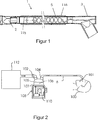
Auf
Als Reaktion auf den vom Benutzer eingestellten Feuchtigkeits- oder Temperaturwert, der zum Beispiel über die Wählscheibe
Es versteht sich, dass die Patientenschnittstelle
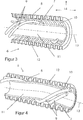
Mit besonderer Bezugnahme auf die
Der Betriff ”glatt” wird dazu verwendet, Schläuche zu beschreiben, die eine Innenfläche ohne innere Wellungen oder ringförmige Rippen oder Buckel oder Vertiefungen, die einen großen Einfluss auf den Strom von Gasen entlang dem Schlauch haben, aufweisen. Der innere Schlauch
Die Anordnung des getrennten inneren Schlauchs
Der innere Schlauch
Bei einer innen beheizten Anordnung (wie zum Beispiel in
Es wird bevorzugt, dass der Heizdraht
Bei alternativen Ausführungsformen können der oder die Heizdrähte
Der innere Schlauch
Auf die
Als Alternative dazu enthält die Innenfläche keine Merkmale, die Gasstromn signifikant stören, zum Beispiel Wellungen, Wülste, Rippen oder Vorsprünge oder Vertiefungen.Alternatively, the interior surface does not contain features that significantly disturb gas flow, for example, corrugations, beads, ridges or protrusions or depressions.
Als Alternative dazu oder zusätzlich dazu kann die Außenfläche des inneren Schlauchs
Bei noch einer weiteren Ausführungsform kann der innere Schlauch
Es hat sich herausgestellt, dass die oben beschriebene Atemschlauchanordnung einen signifikanten Leistungsvorteil bezüglich der Bildung von angesammeltem mobilem Kondensat hat. In dem bestimmten Fall von Atemschläuchen, die für Neonatologieanwendungen (das heißt Atemschläuche mit einem Atemgasdurchgang (
Des Weiteren bildet das im Wesentlichen stagnierende Gas im Raum
Es hat sich herausgestellt, dass die Kombination der oben beschriebenen Merkmale der Isolierung mit im Wesentlichen stagnierendem Gas, direkten Innenschlauchwandbeheizung (außerhalb des Gasstroms) und einer glatten Innenschlauchwand zu einem Atemschlauch mit einem besonders guten Ausregnungsverhalten führt. Des Weiteren hat sich herausgestellt, dass die beschriebene Ausführung besonders für neonatale Anwendungen geeignet ist. Diese Atemschläuche weisen eine Leistungshöhe auf die bisher nicht erreichbar war (das heißt, wenn der Innendurchmesser des inneren Schlauchs weniger als 15 mm beträgt), was zu einem Atemschlauch mit einem sehr guten Ausregnungsverhalten führt, während eine ausreichende Flexibilität bewahrt wird, was ideal für neonatale Anwendungen ist. Es ist wichtig, dass gleichzeitig die Herstellungskosten im Verhältnis zu der signifikanten Leistungsverbesserung nur moderat ansteigen. Dieses Merkmal gestattet die Herstellung eines Atemschlauchs zu Kosten, die für ”einmalige” Anwendungen geeignet sind. Bei einer ganz besonderen Neonatalausführungsform ist der Innendurchmesser auf nicht mehr als 10 mm begrenzt, und der sich ergebende Schlauch kann sogar noch leichter, weniger voluminös und flexibler und besser geeignet für neonatale Anwendungen sein.It has been found that the combination of the above-described features of substantially stagnant gas insulation, direct inner tube wall heating (outside the gas flow) and a smooth inner tube wall results in a breathing tube with a particularly good excitation behavior. Furthermore, it has been found that the described embodiment is particularly suitable for neonatal applications. These breathing tubes have a performance level previously unachievable (that is, when the inner diameter of the inner tube is less than 15 mm), resulting in a breathing tube with very good excitement while maintaining sufficient flexibility, which is ideal for neonatal Applications is. It is important that, at the same time, production costs increase only moderately in relation to the significant improvement in performance. This feature allows the manufacture of a breathing tube at a cost suitable for "one time" applications. In a very particular neonatal embodiment, the inner diameter is limited to no more than 10 mm, and the resulting tube can be even lighter, less bulky and more flexible, and more suitable for neonatal applications.
Bei einer besonders wichtigen Ausführungsform ist der äußere Schlauch
Darüber hinaus hat sich herausgestellt, dass die beschriebenen Atemschlauchanordnungen besonders effektiv sind, wenn sie für Therapien mit hohen Durchflussraten (HHFNC) verwendet werden. Die kombinierte Wirkung der Therapie mit hohen Durchflussraten mit der vorliegenden Atemschlauchausführung führt zu einem wesentlich verbesserten Ausregnungsverhalten, während relativ geringe Kosten bewahrt werden. Diese Kombination ist bisher nicht erreichbar gewesen.In addition, it has been found that the described breathing tube assemblies are particularly effective when used for high flow rate therapies (HHFNC). The combined effect of high flow rate therapy with the present breathing tube design results in significantly improved exercise performance while maintaining relatively low cost. This combination has not been available so far.
Endverbinderend connector
Die Endverbinderanschlüsse
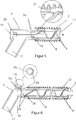
Mit besonderer Bezugnahme auf
Der Heizdraht oder die Heizdrähte
- – Reduzieren der Strömungsstörung
- – Reduzierung der Ausregnung durch direkte Wandbeheizung
- – Reduzierung der Korrosion des Heizdrahts von Kontakt mit Gas hoher Feuchtigkeit, wodurch die Gebrauchsproduktlebensdauer verbessert wird
- – signifikante Erhöhung der Sicherheit, da jegliche elektrischen Fehler, die zum Beispiel Funken/Rauch verursachen könnten, außerhalb des Atemgasstroms (der einen hohen O2-Gehalt haben kann) erfolgen.
- - Reduce the flow disturbance
- - Reduction of excitation by direct wall heating
- Reduction of the corrosion of the heating wire from contact with high-humidity gas, thereby improving the service life of the product
- Significant increase in safety, since any electrical faults that could cause sparks / fumes, for example, are outside of the breathing gas flow (which may have a high O 2 content).
In einem Bereich nahe dem Endverbinder
Bei Ausführungsformen von Atemschläuchen, bei denen alle der Enden des oder der Heizdrähte
Unter besonderer Bezugnahme auf
Alternative Heizdrahtanordnungen und VerfahrenAlternative heating wire arrangements and methods
Bei einer weiteren Ausführungsform können der oder die schraubenförmig angeordneten Heizdrähte eine variierende Steigung entlang der Länge des Atemschlauchs aufweisen. Dies führt zu einer variierenden Heizdichte entlang dem Schlauch, wodurch gestattet wird, dass den verschiedenen Bereichen des Schlauchs, die den größten Bedarf dafür haben, mehr oder weniger Hitze zugeführt wird, zum Beispiel dem Kammerende, an dem in der Regel bei einem Einatemschlauch die stärkste Ausregnung erfolgt. Dies ist darauf zurückzuführen, dass das Gas in der Regel am Kammerauslass vollständig gesättigt ist. Der Einatemschlauch wird erwärmt, um die Gastemperatur innerhalb des Schlauchs zu erhöhen, wodurch die relative Feuchtigkeit (und das Ausregnungspotenzial) des Gases bei seinem Strom zu dem Patientenende verringert werden.In another embodiment, the helically arranged heating wire (s) may have a varying pitch along the length of the breathing tube. This results in a varying density of heating along the hose, allowing more or less heat to be supplied to the various regions of the hose that are most in need, for example, the chamber end, which is usually the strongest in a breathing tube Excitement takes place. This is because the gas is usually completely saturated at the chamber outlet. The inhalation tube is heated to increase the gas temperature within the tube, thereby reducing the relative humidity (and excitation potential) of the gas as it flows to the patient end.
Bei einer weiteren alternativen Ausführungsform können die Heizdrähte
Der Windungsprozess kann in Abhängigkeit von den gewünschten Verbindungsvorrichtungen und dem oder den Schlauchhandhabungsverfahren auf verschiedene Weise durchgeführt werden.The winding process may be performed in various ways depending on the desired connection devices and the hose handling method (s).
Vorher als Schleife ausgebildetes spiralförmiges Heizfilament.
- – Bei dieser Ausführungsform werden der oder die Drähte auf ein Speichersystem vorgeladen und samt einer Schleife in der Mitte umgefaltet. Der oder die Drahtschleifen werden dann auf den Schlauch gewunden.
- In this embodiment, the wire (s) are preloaded onto a storage system and folded over with a loop in the middle. The one or more wire loops are then wound on the hose.
Gepaarte Heizfilamente mit Verbindungen am Patientenende.
- – Bei dieser Ausführungsform wird das Patientenende der Paare von Drahtsträngen zusammengefügt und kann einer weiteren Befestigung mit zum Beispiel Heißschmelzkleber oder UV-aushärtendem Klebstoff bedürfen. Dann dreht sich eine Wickeleinrichtung um den Schlauch und bringt gleichzeitig gemäß der Anzahl von Drahtpaaren gepaarte Drahtstränge von getrennten Spulen an, um der Anzahl von Helices pro Steigung und den gewünschten Drahtanordnungen Rechnung zu tragen. Die Drähte können auch eine Befestigung mit zum Beispiel Heißschmelzkleber oder UV-ausgehärtetem Klebstoff erfordern. Der äußere Schlauch wird anschließend angebracht, und dann werden die Schläuche in den Endverbindern befestigt. Schließlich werden die elektrischen Endanschlüsse fertiggestellt.
- In this embodiment, the patient end of the pairs of wire strands is assembled and may require further attachment with, for example, hot melt adhesive or UV-curing adhesive. Then, a winder rotates around the tube and simultaneously applies paired wire strands of separate coils according to the number of wire pairs to account for the number of helices per pitch and the desired wire arrangements. The wires may also require attachment with, for example, hot melt adhesive or UV cured adhesive. The outer tube is then attached, and then the tubes are secured in the end connectors. Finally, the electrical end connections are completed.
Bei einer weiteren Ausführungsform kommt in Betracht, dass die schraubenförmigen Heizdrähte auch Signale für Erfassungsvorrichtungen, die an irgendeiner Stelle entlang dem Schlauch positioniert sind, das heißt Temperatur-, Feuchtigkeits-, Strömungs- oder Drucksensoren, übertragen können. Aufgrund dessen könnte auf getrennte innere oder äußere Erfassungsvorrichtungskabel verzichtet werden, wodurch die Aufbaukomplexität um den Patienten herum reduziert und seine Umgebung übersichtlicher werden würde. Als Alternative dazu können zusätzliche Drahtwindungen für diesen Zweck enthalten sein.In another embodiment, it is contemplated that the helical heating wires may also transmit signals to sensing devices positioned anywhere along the tube, that is, temperature, humidity, flow, or pressure sensors. Because of this, separate internal or external detector cables could be dispensed with, thereby reducing structural complexity around the patient and making his environment clearer. Alternatively, additional wire turns may be included for this purpose.
Ausregnungsverhalten Ausregnungsverhalten
Ein trockener Schlauchsatz von 1,8 m wurde gewogen und dann an einem Befeuchtungssystem MR850 von Fisher and Paykel Healthcare in einer auf 18°C eingestellten temperaturkontrollierten Klimakammer eingerichtet. Dem MR850-System wurde gestattet, sich normal auf eine Kammertemperatur von 37°C und eine Schlauchendentemperatur von 40°C bei einer konstanten Durchflussrate von 5 Liter pro Minute zu steuern.A 1.8 meter dry hose set was weighed and then set up on a Fisher and Paykel Healthcare MR850 humidification system in a temperature controlled climatic chamber set at 18 ° C. The MR850 system was allowed to normally control to a chamber temperature of 37 ° C and a tube end temperature of 40 ° C at a constant flow rate of 5 liters per minute.
Der Test wurde 24 Stunden lang durchgeführt, wonach der Schlauch entfernt und gewogen wurde, um die in dem Atemschlauch akkumulierte Kondensatmenge zu messen.The test was performed for 24 hours, after which the tube was removed and weighed to measure the amount of condensate accumulated in the breathing tube.
Zum Vergleich wurden ein typischer Atemschlauch, wie zum Beispiel der in
Atemschlauch für ErwachseneBreathing tube for adults
Bei einer anderen bestimmten Ausführungsform weist der medizinische Schlauch der vorliegenden Erfindung eine Nennbohrungsgröße von ca. 15 mm bis ca. 30 mm und Längen von ca. 300 mm bis 2,5 m auf.In another particular embodiment, the medical tubing of the present invention has a nominal bore size of about 15 mm to about 30 mm and lengths of about 300 mm to 2.5 m.
Bei dieser alternativen Ausführungsform ist die Struktur des Atemschlauchs für Erwachsene im Wesentlichen die gleiche wie die für die kleinere Neonatalausführungsform beschriebene, jedoch mit einem vergrößerten Durchmesser des inneren Schlauchs
Ein Extruder
Bevorzugte Materialien für die Heizdrähte sind Kupfer, Aluminium oder ein PTC-Material (PTC – positiver Temperaturkoeffizient). Aluminium ist nicht so leitend wie Kupfer, kann aber eine wirtschaftliche Wahl sein, obgleich der Drahtdurchmesser bei gleichem Widerstand größer ist Obgleich die angelegte Betriebsspannung eigensicher ist (unter 50 V), ist für Korrosionswiderstand und der besten elektrischen Sicherheit bei einer Beschädigung des Schlauchs der Draht idealerweise selbstisoliert, entweder durch einen Emailüberzug oder bei Aluminium durch Anodisieren. Als Alternative kann ein extrudierter Kunststoffmantel angebracht werden.Preferred materials for the heating wires are copper, aluminum or a PTC material (PTC - positive temperature coefficient). Aluminum is not as conductive as copper, but can be an economical choice, although the wire diameter is larger with equal resistance. Although the applied operating voltage is intrinsically safe (below 50V), the wire is resistant to corrosion and the best electrical safety in the event of hose damage ideally self-insulated, either by an enamel coating or aluminum by anodizing. Alternatively, an extruded plastic sheath may be applied.
Die vorangehende Beschreibung der Erfindung enthält bevorzugte Formen davon. Es können daran Modifikationen durchgeführt werden, ohne vom Schutzbereich der Erfindung abzuweichen. Für einen Fachmann auf dem Gebiet, auf das sich die Erfindung bezieht, bieten sich viele Änderungen an der Ausführung und stark verschiedene Ausführungsformen und Anwendungen der Erfindung an, ohne dass der in den angehängten vorläufigen Ansprüchen definierte Schutzbereich der Erfindung verlassen wird. Die Offenbarungen und die Beschreibungen in dieser Schrift sind rein veranschaulichend und sollen in keiner Weise einschränkend sein. The foregoing description of the invention includes preferred forms thereof. Modifications may be made thereto without departing from the scope of the invention. For a person skilled in the art to which the invention relates, many modifications to the embodiment and greatly different embodiments and applications of the invention are possible without departing from the scope of protection of the invention as defined in the appended provisional claims. The disclosures and descriptions in this document are merely illustrative and are not intended to be limiting in any way.
ZITATE ENTHALTEN IN DER BESCHREIBUNG QUOTES INCLUDE IN THE DESCRIPTION
Diese Liste der vom Anmelder aufgeführten Dokumente wurde automatisiert erzeugt und ist ausschließlich zur besseren Information des Lesers aufgenommen. Die Liste ist nicht Bestandteil der deutschen Patent- bzw. Gebrauchsmusteranmeldung. Das DPMA übernimmt keinerlei Haftung für etwaige Fehler oder Auslassungen.This list of the documents listed by the applicant has been generated automatically and is included solely for the better information of the reader. The list is not part of the German patent or utility model application. The DPMA assumes no liability for any errors or omissions.
Zitierte Nicht-PatentliteraturCited non-patent literature
- ISO 5367:2000''E [0072] ISO 5367: 2000''E [0072]
Claims (47)
Applications Claiming Priority (3)
| Application Number | Priority Date | Filing Date | Title |
|---|---|---|---|
| US34802010P | 2010-05-25 | 2010-05-25 | |
| US61/348,020 | 2010-05-25 | ||
| PCT/NZ2011/000076 WO2011149362A1 (en) | 2010-05-25 | 2011-05-13 | Improved breathing tube |
Publications (1)
| Publication Number | Publication Date |
|---|---|
| DE112011101780T5 true DE112011101780T5 (en) | 2013-03-14 |
Family
ID=45004152
Family Applications (1)
| Application Number | Title | Priority Date | Filing Date |
|---|---|---|---|
| DE112011101780T Pending DE112011101780T5 (en) | 2010-05-25 | 2011-05-13 | Improved breathing tube |
Country Status (5)
| Country | Link |
|---|---|
| US (4) | US9295801B2 (en) |
| JP (1) | JP6005631B2 (en) |
| DE (1) | DE112011101780T5 (en) |
| GB (1) | GB2492736B (en) |
| WO (1) | WO2011149362A1 (en) |
Families Citing this family (39)
| Publication number | Priority date | Publication date | Assignee | Title |
|---|---|---|---|---|
| EP3075406A1 (en) | 2008-04-30 | 2016-10-05 | ResMed R&D Germany GmbH | Apparatus and method for controlled delivery of a breathing gas to the respiratory tracts of a user |
| DE102008022663B4 (en) | 2008-05-07 | 2012-10-31 | Schauenburg Hose Technology Gmbh | Stretch hose |
| US9505164B2 (en) | 2009-12-30 | 2016-11-29 | Schauenburg Technology Se | Tapered helically reinforced hose and its manufacture |
| US9964238B2 (en) | 2009-01-15 | 2018-05-08 | Globalmed, Inc. | Stretch hose and hose production method |
| WO2011149362A1 (en) * | 2010-05-25 | 2011-12-01 | Fisher & Paykel Healthcare Limited | Improved breathing tube |
| WO2013055235A1 (en) | 2011-10-14 | 2013-04-18 | Fisher & Paykel Healthcare Limited | Medical tubes and methods of manufacture |
| AU2013232848B2 (en) | 2012-03-15 | 2018-03-22 | Fisher & Paykel Healthcare Limited | Respiratory gas humidification system |
| EP2841137B1 (en) | 2012-04-27 | 2019-12-25 | Fisher & Paykel Healthcare Limited | Usability features for respiratory humidification system |
| US9272114B2 (en) * | 2012-06-18 | 2016-03-01 | Flexible Technologies, Inc. | Heated CPAP hose and fitting |
| EP2968823B8 (en) | 2013-03-15 | 2022-02-16 | Fisher & Paykel Healthcare Limited | Components for medical circuits |
| WO2014142679A1 (en) | 2013-03-15 | 2014-09-18 | Fisher & Paykel Healthcare Limited | Drying expiratory limb with tailored temperature profile and multi-lumen configuration |
| US10549060B2 (en) | 2013-06-25 | 2020-02-04 | ResMed Pty Ltd | Outlet connection assembly and method of making the same |
| NZ749247A (en) | 2013-06-25 | 2020-06-26 | ResMed Pty Ltd | Outlet connection assembly and method of making the same |
| CN108704213B (en) | 2013-09-13 | 2021-06-22 | 费雪派克医疗保健有限公司 | Connection for humidification system |
| CN114392433A (en) | 2013-12-17 | 2022-04-26 | 瑞思迈私人有限公司 | Respiratory pressure therapy system |
| JP6455653B2 (en) * | 2013-12-26 | 2019-01-23 | 株式会社メトラン | Filter structure |
| US10449319B2 (en) | 2014-02-07 | 2019-10-22 | Fisher & Paykel Healthcare Limited | Respiratory humidification system |
| USD762843S1 (en) | 2014-03-18 | 2016-08-02 | Resmed Limited | Air delivery tube |
| US11324911B2 (en) | 2014-06-03 | 2022-05-10 | Fisher & Paykel Healthcare Limited | Flow mixers for respiratory therapy systems |
| CN117414515A (en) * | 2014-07-07 | 2024-01-19 | 费雪派克医疗保健有限公司 | Medical tube and connector for gas delivery system |
| JP6399597B2 (en) * | 2014-12-16 | 2018-10-03 | アトムメディカル株式会社 | Respiratory gas heating humidifier |
| WO2016145211A1 (en) * | 2015-03-10 | 2016-09-15 | Life Warmer Inc. | Thermic infusion system |
| US11471636B2 (en) * | 2015-04-15 | 2022-10-18 | Medline Industries, Lp | Moisture removal and condensation and humidity management apparatus for a breathing circuit |
| US10500366B2 (en) | 2015-04-27 | 2019-12-10 | Teleflex Medical Incorporated | Humidification device |
| EP3851148A1 (en) * | 2015-06-24 | 2021-07-21 | Fisher & Paykel Healthcare Limited | Breathing assistance apparatus |
| WO2017036500A1 (en) * | 2015-08-28 | 2017-03-09 | Plastiflex Group | Breathing circuit for use in a respiratory system |
| USD805630S1 (en) | 2016-02-02 | 2017-12-19 | Resmed Limited | Air delivery tube |
| WO2018075638A1 (en) * | 2016-10-19 | 2018-04-26 | Teleflex Medical Incorporated | Moisture removal and condensation and humidity management apparatus for a breathing circuit |
| WO2018081272A1 (en) | 2016-10-26 | 2018-05-03 | Teleflex Medical Incorporated | System and method for on-demand near-patient humidification |
| SG10202106016TA (en) | 2016-12-07 | 2021-07-29 | Fisher and paykel healthcare ltd | Sensing arrangements for medical devices |
| CA3033944C (en) | 2017-01-30 | 2020-02-18 | Globalmed, Inc. | Heated respiratory hose assembly |
| EP3651843B1 (en) | 2017-07-10 | 2022-12-07 | Medline Industries, LP | Moisture removal and condensation and humidity management apparatus for a breathing circuit |
| JP2020534895A (en) * | 2017-09-28 | 2020-12-03 | コーニンクレッカ フィリップス エヌ ヴェKoninklijke Philips N.V. | Inflatable conduit and headgear including the inflatable conduit |
| WO2019203664A1 (en) | 2018-04-18 | 2019-10-24 | Fisher & Paykel Healthcare Limited | Conduits and other components with wicking properties and associated methods |
| CN110882499B (en) * | 2018-09-10 | 2024-03-19 | 李丹 | Cold and heat exchange filter element and mask |
| CN109966620A (en) * | 2018-09-27 | 2019-07-05 | 李冬兰 | A kind of ICU absorption in postoperative patients of cardiac surgery care device |
| CN109876257A (en) * | 2019-03-28 | 2019-06-14 | 广州鲸科医疗科技有限公司 | A kind of pipeline of inhaling therapeutical instrument |
| CN109876256A (en) * | 2019-03-28 | 2019-06-14 | 广州鲸科医疗科技有限公司 | A kind of inhaling therapeutical instrument |
| CN112604111A (en) * | 2020-12-25 | 2021-04-06 | 北京怡和嘉业医疗科技股份有限公司 | Respiratory gas delivery pipe, nasal catheter and ventilation treatment equipment |
Family Cites Families (61)
| Publication number | Priority date | Publication date | Assignee | Title |
|---|---|---|---|---|
| US1596754A (en) * | 1923-10-30 | 1926-08-17 | Judson D Moschelle | Reenforced tubing |
| US2516864A (en) | 1948-08-24 | 1950-08-01 | Gen Electric | Method of making hose from elastomeric composition |
| US3490496A (en) * | 1968-01-15 | 1970-01-20 | Vacuum Barrier Corp | Coaxial tubing having improved spacer means |
| BE793596A (en) | 1972-01-03 | 1973-05-02 | Dayco Corp | FLEXIBLE ELASTOMERIC HOSE, ESPECIALLY FOR VACUUM CLEANERS |
| US3867946A (en) * | 1973-10-29 | 1975-02-25 | Robert A Huddy | Binasopharyngeal airway |
| US4098298A (en) * | 1973-12-14 | 1978-07-04 | Herbert Vohrer | Hose |
| JPS5184296U (en) * | 1974-12-27 | 1976-07-06 | ||
| JPS5184296A (en) | 1975-01-20 | 1976-07-23 | Sanyo Electric Co | JIDOHANBAIKINOSHOHINSHUNOCHOSEISOCHI |
| US4214147A (en) * | 1978-06-19 | 1980-07-22 | Kraver Richard A | Electric heating system for controlling temperature of pipes to prevent freezing and condensation |
| FR2464819A1 (en) | 1979-09-10 | 1981-03-20 | Pont A Mousson | TUBE OF PLASTIC MATERIAL OBTAINED BY WINDING WITH A PROFILE |
| DE3246247A1 (en) | 1982-12-14 | 1984-06-14 | Siemens AG, 1000 Berlin und 8000 München | DOUBLE-WALLED, FLEXIBLE HOSE |
| FI82133C (en) | 1988-08-17 | 1991-01-10 | Kwh Pipe Ab Oy | SPIRALLINDAT ROER. |
| US4967744A (en) * | 1988-11-03 | 1990-11-06 | Airoflex Medical, Inc. | Flexible breathing circuit |
| DE9200567U1 (en) * | 1992-01-18 | 1992-07-02 | Hew - Kabel Heinz Eilentropp Kg, 5272 Wipperfuerth, De | |
| US5381511A (en) * | 1993-06-02 | 1995-01-10 | W. L. Gore & Associates, Inc. | Flexible electrically heatable hose |
| US5600752A (en) * | 1994-03-11 | 1997-02-04 | Industrial Design Laboratories, Inc. | Flexible gas hose assembly with concentric helical tube members having reinforcement spring coils |
| JPH08109984A (en) | 1994-03-15 | 1996-04-30 | Fisher & Paykel Ltd | Conduit for forwarding humidified gas and manufacturing process thereof |
| US5848223A (en) * | 1994-05-27 | 1998-12-08 | Steward Plastics, Inc. | Double-walled flexible tubing product with helical support bead and heating conductor and apparatus and method for making |
| WO1997018001A1 (en) * | 1995-11-13 | 1997-05-22 | Fisher & Paykel Limited | Heated respiratory conduit |
| CN2243015Y (en) | 1996-03-15 | 1996-12-18 | 许建新 | Sealed telescopic metal flexible tube |
| DE19617095C1 (en) * | 1996-04-29 | 1997-12-04 | Ruesch Willy Ag | Heated ventilation hose |
| FR2766547B1 (en) | 1997-07-24 | 1999-09-17 | Gessil | FLEXIBLE CONDUIT, FOR EXAMPLE HOSE FOR MEDICAL OR SURGICAL USE |
| JPH11286058A (en) | 1998-03-31 | 1999-10-19 | Takiron Co Ltd | Production of plastic corrugated pipe |
| US6354332B1 (en) * | 1999-04-30 | 2002-03-12 | Witzenmann Gmbh, Metallschlauch-Fabrik Pforzheim | Coolant line for air conditioning systems |
| US6435180B1 (en) * | 1999-07-01 | 2002-08-20 | J&M Distributors Limited | Method and apparatus for delivering humidified air to a face mask |
| AU775872B2 (en) * | 1999-08-10 | 2004-08-19 | Fisher & Paykel Healthcare Limited | A ventilation system and/or breathing tube |
| JP4578644B2 (en) * | 1999-10-13 | 2010-11-10 | 大陽日酸株式会社 | Dry ice snow jet cleaning device and cleaning method |
| DE10007506B4 (en) * | 2000-02-18 | 2006-02-02 | Map Medizin-Technologie Gmbh | Breathing gas hose assembly for supplying a breathing gas |
| JP4406177B2 (en) * | 2000-06-21 | 2010-01-27 | フィッシャー アンド ペイケル ヘルスケア リミテッド | Breathing circuit lumen and breathing circuit |
| US20040244858A1 (en) | 2001-07-24 | 2004-12-09 | In-Seon Jeong | Spiral hose using polyethylene |
| JP2003111774A (en) * | 2001-07-31 | 2003-04-15 | Senko Medical Instr Mfg Co Ltd | Heating and humidifying device for pneumoperitoneum gas and pneumoperitoneum apparatus |
| JP2003139276A (en) | 2001-11-06 | 2003-05-14 | Tomonao Ikeda | Universal pipe |
| US6769452B2 (en) * | 2001-11-20 | 2004-08-03 | Dqp, Llc | Leak-free flexible conduit |
| US6953354B2 (en) * | 2002-06-05 | 2005-10-11 | Fisher & Paykel Healthcare Limited | Connector for breathing conduits |
| US7291240B2 (en) | 2002-09-09 | 2007-11-06 | Fisher & Paykel Healthcare Limited | Method of forming a conduit using a wound sacrificial layer |
| EP1545863B1 (en) | 2002-09-11 | 2009-08-19 | Fisher & Paykel Healthcare Limited | Conduits and method of forming |
| US8016752B2 (en) | 2003-01-17 | 2011-09-13 | Gore Enterprise Holdings, Inc. | Puncturable catheter |
| US7766050B2 (en) | 2003-11-28 | 2010-08-03 | Fisher & Paykel Healthcare Limited | Conduit and method of forming |
| US9022036B2 (en) * | 2004-03-31 | 2015-05-05 | Fisher & Paykel Healthcare Limited | Patient ventilating and aspirating system |
| EP3766534B1 (en) * | 2004-08-20 | 2022-09-28 | Fisher & Paykel Healthcare Limited | Apparatus for measuring properties of gases supplied to a patient |
| US20070016272A1 (en) * | 2004-09-27 | 2007-01-18 | Thompson Russell B | Systems and methods for treating a hollow anatomical structure |
| US20060201504A1 (en) * | 2005-03-08 | 2006-09-14 | Singhal Aneesh B | High-flow oxygen delivery system and methods of use thereof |
| US8733405B2 (en) * | 2005-03-14 | 2014-05-27 | Advanced Drainage Systems, Inc. | Corrugated pipe with outer layer |
| GB0521349D0 (en) | 2005-10-20 | 2005-11-30 | Intersurgical Ltd | Improvements relating to ventilation tubes |
| WO2007109837A1 (en) * | 2006-03-24 | 2007-10-04 | Resmed Ltd | Air delivery conduit |
| US8888747B2 (en) * | 2006-10-12 | 2014-11-18 | Adapta Medical, Inc. | Catheter assembly with vents |
| EP4176915A1 (en) * | 2006-11-08 | 2023-05-10 | ResMed Pty Ltd | Respiratory apparatus |
| KR20080043893A (en) | 2006-11-15 | 2008-05-20 | 박재영 | Method and device for manufacturing plastic multiple-walled tube and plastic-walled thereof |
| US8312875B2 (en) * | 2007-01-11 | 2012-11-20 | Resmed Limited | Fastenable conduit for breathable gas delivery |
| US8944056B2 (en) * | 2007-02-09 | 2015-02-03 | Resmed Limited | Humidification arrangement for a respiratory apparatus |
| EP2195061B1 (en) * | 2007-08-14 | 2018-08-22 | Plastiflex Group | A respiratory system |
| EP2240245A1 (en) * | 2008-01-18 | 2010-10-20 | Breathe Technologies, Inc. | Methods and devices for improving efficacy of non-invasive ventilation |
| EP2153859B1 (en) * | 2008-08-13 | 2015-12-23 | Drägerwerk AG & Co. KGaA | Medical ventilation system |
| DE102008039137B3 (en) | 2008-08-21 | 2010-02-11 | Dräger Medical AG & Co. KG | Ventilator with a breathing circuit |
| US9915380B2 (en) * | 2009-06-29 | 2018-03-13 | Dura-Line Corporation | Multi-layer tubular conduit |
| US20110061658A1 (en) * | 2009-08-12 | 2011-03-17 | Robert Koorn | Oropharyngeal devices for use in ventilating patients |
| CN201672170U (en) | 2010-04-27 | 2010-12-15 | 吴耕田 | Structured-wall pipe molded and wound from fibrous composite material |
| WO2011149362A1 (en) * | 2010-05-25 | 2011-12-01 | Fisher & Paykel Healthcare Limited | Improved breathing tube |
| EP2442003A1 (en) * | 2010-10-11 | 2012-04-18 | Alcatel Lucent | Thermally insulated pipe and method of manufacturing a thermally insulated pipe |
| GB2557121B (en) | 2011-06-03 | 2018-12-05 | Fisher & Paykel Healthcare Ltd | Medical tubes and methods of manufacture |
| US9113501B2 (en) * | 2012-05-25 | 2015-08-18 | Watlow Electric Manufacturing Company | Variable pitch resistance coil heater |
-
2011
- 2011-05-13 WO PCT/NZ2011/000076 patent/WO2011149362A1/en active Application Filing
- 2011-05-13 JP JP2013512562A patent/JP6005631B2/en active Active
- 2011-05-13 GB GB1220545.6A patent/GB2492736B/en active Active
- 2011-05-13 US US13/698,272 patent/US9295801B2/en active Active
- 2011-05-13 DE DE112011101780T patent/DE112011101780T5/en active Pending
-
2016
- 2016-02-23 US US15/051,589 patent/US10195388B2/en active Active
-
2018
- 2018-12-20 US US16/228,262 patent/US11135391B2/en active Active
-
2021
- 2021-08-24 US US17/445,793 patent/US20220072259A1/en active Pending
Non-Patent Citations (1)
| Title |
|---|
| ISO 5367:2000''E |
Also Published As
| Publication number | Publication date |
|---|---|
| US10195388B2 (en) | 2019-02-05 |
| JP6005631B2 (en) | 2016-10-12 |
| WO2011149362A1 (en) | 2011-12-01 |
| US20130112201A1 (en) | 2013-05-09 |
| US11135391B2 (en) | 2021-10-05 |
| JP2013526976A (en) | 2013-06-27 |
| US20160279374A1 (en) | 2016-09-29 |
| US20190192807A1 (en) | 2019-06-27 |
| GB2492736A (en) | 2013-01-09 |
| US20220072259A1 (en) | 2022-03-10 |
| GB2492736B (en) | 2014-12-17 |
| GB201220545D0 (en) | 2013-01-02 |
| US9295801B2 (en) | 2016-03-29 |
Similar Documents
| Publication | Publication Date | Title |
|---|---|---|
| DE112011101780T5 (en) | Improved breathing tube | |
| DE60020024T2 (en) | ventilation system | |
| US11358318B2 (en) | Component for conveying gases | |
| DE112013005798T5 (en) | Medical tube and manufacturing process | |
| US10688270B2 (en) | Components for medical circuits | |
| DE102008039137B3 (en) | Ventilator with a breathing circuit | |
| EP2374494B1 (en) | Nose piece for nasal cannula | |
| DE112012002347T5 (en) | Medical tubes and methods of making same | |
| DE112014001468T5 (en) | Components for medical circuits | |
| DE112015001316T5 (en) | Medical tubes for ventilation systems | |
| DE112013005443T5 (en) | Zone heating for breathing circuits | |
| DE202006007397U1 (en) | Ventilation hose with different heating zones | |
| GB2431359A (en) | Respirator tube heated by helical wire | |
| DE102011014018B4 (en) | Apparatus for filtering respiratory gas | |
| EP3846890B1 (en) | Heatable breathing tube and method for the production thereof | |
| DE102010051079A1 (en) | Heated breathing circuit | |
| DE202004020412U1 (en) | Ventilation system and heated tube arrangement with temperature sensor for a respiratory system |
Legal Events
| Date | Code | Title | Description |
|---|---|---|---|
| R012 | Request for examination validly filed |