JP6673276B2 - Voice detection device, voice detection method, and program - Google Patents
Voice detection device, voice detection method, and program Download PDFInfo
- Publication number
- JP6673276B2 JP6673276B2 JP2017062756A JP2017062756A JP6673276B2 JP 6673276 B2 JP6673276 B2 JP 6673276B2 JP 2017062756 A JP2017062756 A JP 2017062756A JP 2017062756 A JP2017062756 A JP 2017062756A JP 6673276 B2 JP6673276 B2 JP 6673276B2
- Authority
- JP
- Japan
- Prior art keywords
- sound source
- sound
- voice
- detected
- robot
- Prior art date
- Legal status (The legal status is an assumption and is not a legal conclusion. Google has not performed a legal analysis and makes no representation as to the accuracy of the status listed.)
- Active
Links
Images


Classifications
-
- G—PHYSICS
- G10—MUSICAL INSTRUMENTS; ACOUSTICS
- G10L—SPEECH ANALYSIS OR SYNTHESIS; SPEECH RECOGNITION; SPEECH OR VOICE PROCESSING; SPEECH OR AUDIO CODING OR DECODING
- G10L15/00—Speech recognition
- G10L15/22—Procedures used during a speech recognition process, e.g. man-machine dialogue
-
- G—PHYSICS
- G10—MUSICAL INSTRUMENTS; ACOUSTICS
- G10L—SPEECH ANALYSIS OR SYNTHESIS; SPEECH RECOGNITION; SPEECH OR VOICE PROCESSING; SPEECH OR AUDIO CODING OR DECODING
- G10L25/00—Speech or voice analysis techniques not restricted to a single one of groups G10L15/00 - G10L21/00
- G10L25/78—Detection of presence or absence of voice signals
-
- G—PHYSICS
- G06—COMPUTING; CALCULATING OR COUNTING
- G06V—IMAGE OR VIDEO RECOGNITION OR UNDERSTANDING
- G06V40/00—Recognition of biometric, human-related or animal-related patterns in image or video data
- G06V40/10—Human or animal bodies, e.g. vehicle occupants or pedestrians; Body parts, e.g. hands
- G06V40/16—Human faces, e.g. facial parts, sketches or expressions
- G06V40/161—Detection; Localisation; Normalisation
-
- G—PHYSICS
- G06—COMPUTING; CALCULATING OR COUNTING
- G06V—IMAGE OR VIDEO RECOGNITION OR UNDERSTANDING
- G06V40/00—Recognition of biometric, human-related or animal-related patterns in image or video data
- G06V40/10—Human or animal bodies, e.g. vehicle occupants or pedestrians; Body parts, e.g. hands
- G06V40/16—Human faces, e.g. facial parts, sketches or expressions
- G06V40/172—Classification, e.g. identification
-
- G—PHYSICS
- G10—MUSICAL INSTRUMENTS; ACOUSTICS
- G10L—SPEECH ANALYSIS OR SYNTHESIS; SPEECH RECOGNITION; SPEECH OR VOICE PROCESSING; SPEECH OR AUDIO CODING OR DECODING
- G10L15/00—Speech recognition
- G10L15/24—Speech recognition using non-acoustical features
-
- G—PHYSICS
- G10—MUSICAL INSTRUMENTS; ACOUSTICS
- G10L—SPEECH ANALYSIS OR SYNTHESIS; SPEECH RECOGNITION; SPEECH OR VOICE PROCESSING; SPEECH OR AUDIO CODING OR DECODING
- G10L17/00—Speaker identification or verification
-
- G—PHYSICS
- G10—MUSICAL INSTRUMENTS; ACOUSTICS
- G10L—SPEECH ANALYSIS OR SYNTHESIS; SPEECH RECOGNITION; SPEECH OR VOICE PROCESSING; SPEECH OR AUDIO CODING OR DECODING
- G10L17/00—Speaker identification or verification
- G10L17/22—Interactive procedures; Man-machine interfaces
-
- G—PHYSICS
- G10—MUSICAL INSTRUMENTS; ACOUSTICS
- G10L—SPEECH ANALYSIS OR SYNTHESIS; SPEECH RECOGNITION; SPEECH OR VOICE PROCESSING; SPEECH OR AUDIO CODING OR DECODING
- G10L15/00—Speech recognition
- G10L15/02—Feature extraction for speech recognition; Selection of recognition unit
-
- G—PHYSICS
- G10—MUSICAL INSTRUMENTS; ACOUSTICS
- G10L—SPEECH ANALYSIS OR SYNTHESIS; SPEECH RECOGNITION; SPEECH OR VOICE PROCESSING; SPEECH OR AUDIO CODING OR DECODING
- G10L15/00—Speech recognition
- G10L15/22—Procedures used during a speech recognition process, e.g. man-machine dialogue
- G10L2015/223—Execution procedure of a spoken command
-
- G—PHYSICS
- G10—MUSICAL INSTRUMENTS; ACOUSTICS
- G10L—SPEECH ANALYSIS OR SYNTHESIS; SPEECH RECOGNITION; SPEECH OR VOICE PROCESSING; SPEECH OR AUDIO CODING OR DECODING
- G10L15/00—Speech recognition
- G10L15/22—Procedures used during a speech recognition process, e.g. man-machine dialogue
- G10L2015/226—Procedures used during a speech recognition process, e.g. man-machine dialogue using non-speech characteristics
- G10L2015/227—Procedures used during a speech recognition process, e.g. man-machine dialogue using non-speech characteristics of the speaker; Human-factor methodology
-
- G—PHYSICS
- G10—MUSICAL INSTRUMENTS; ACOUSTICS
- G10L—SPEECH ANALYSIS OR SYNTHESIS; SPEECH RECOGNITION; SPEECH OR VOICE PROCESSING; SPEECH OR AUDIO CODING OR DECODING
- G10L25/00—Speech or voice analysis techniques not restricted to a single one of groups G10L15/00 - G10L21/00
- G10L25/78—Detection of presence or absence of voice signals
- G10L2025/783—Detection of presence or absence of voice signals based on threshold decision
Description
本発明は、音声検出装置、音声検出方法、及びプログラムに関する。 The present invention relates to a voice detection device, a voice detection method, and a program.
人間、動物等に模した形態を有し、人間と会話等のコミュニケーションをすることができるロボットが知られている。このようなロボットには、自機に搭載されたマイクの出力に基づいてロボットの周囲に発生した音を検出し、人の声であると判別すると、人がいる方向にロボットの顔の向きあるいは体の向きを変え、その人に話しかける、手を振る等の動作をするものもある。 2. Description of the Related Art A robot having a form imitating a human or an animal and capable of communicating with a human, such as a conversation, is known. Such a robot detects a sound generated around the robot based on the output of a microphone mounted on the robot and determines that the sound is a human voice. Others turn around, talk to the person, or wave their hand.
特許文献1には、ロボットが、マイクロホンに閾値以上の振幅の音が入力されることにより、音イベントが発生したことを検出し、音源方向を推定して、推定した音源方向に振り向くことが記載されている。
しかしながら、特許文献1に記載されているロボットは、音イベントを検出すると振り向くので、実際にロボットに対して人から発せられた音だけではなく、例えば、テレビ、ラジオ等の電子機器のスピーカから出力される音声にも反応してしまうことが予想される。
However, since the robot described in
本発明は、上記実情を鑑みてなされたものであり、ロボットに実際の人から直接発せられた音声か電子機器のスピーカから出力された音声かを判別させることで、ロボットの無駄な動作を減らすことを目的とする。 The present invention has been made in view of the above circumstances, and reduces unnecessary operation of a robot by causing a robot to determine whether the sound is directly emitted from a real person or is output from a speaker of an electronic device. The purpose is to:
上記目的を達成するため、本発明に係る音声検出装置は、
音声を検出する音声検出手段と、
前記音声検出手段により検出された音声である検出音声の音声発生源が特定の音声発生源であるか否かを判別する第1判別手段と、
前記第1判別手段の判別結果に基づいて自機を制御する制御手段と、
前記検出音声が発生した方向を判別する第2判別手段と、
前記特定の音声発生源以外の他の音声発生源の位置を示す情報を含む音声発生源位置情報を記憶した記憶部と、
前記第2判別手段による判別結果と前記記憶された音声発生源位置情報とに基づいて、前記自機に対する前記検出音声が発生した方向に前記他の音声発生源が存在するか否かを判別する第3判別手段と、を備え、
前記制御手段は、前記第3判別手段により前記検出音声が発生した方向に前記他の音声発生源が存在しないと判別されている場合に、前記自機の動作を制御する。
To achieve the above object, a voice detection device according to the present invention includes:
Voice detection means for detecting voice;
First determining means for determining whether or not the sound source of the detected sound which is the sound detected by the sound detecting means is a specific sound source;
Control means for controlling the own device based on the determination result of the first determination means;
Second determining means for determining a direction in which the detected sound is generated;
A storage unit that stores sound source position information including information indicating the position of another sound source other than the specific sound source,
Based on the determination result by the second determination unit and the stored voice source position information, it is determined whether the other voice source is present in the direction in which the detected voice is generated for the own device. And third determining means.
The controller controls the operation of the own device when the third determiner determines that the other sound source does not exist in the direction in which the detected sound is generated .
本発明によれば、ロボットに実際の人から直接発せられた音声か電子機器のスピーカから出力された音声かを判別させることで、ロボットの無駄な動作を減らすことができる。 According to the present invention, it is possible to reduce unnecessary operation of the robot by causing the robot to determine whether the sound is directly uttered from an actual person or is output from a speaker of an electronic device.
(実施の形態1)
以下、図面を参照しながら本発明の実施の形態1について説明する。図1は、実施の形態1に係るロボット100を正面から見た場合の外観を模式的に示した図である。ロボット100は、頭110と胴体120とを備えた人型のコミュニケーションロボットである。ロボット100は、住宅内に設置されており、住人に呼びかけられると、呼びかけた住人と会話する。
(Embodiment 1)
Hereinafter,
図1に示すように、ロボット100の頭110には、カメラ111と、マイク112と、スピーカ113と、が設けられている。
As shown in FIG. 1, a
カメラ111(撮像手段)は、頭110の前面の下側、人の顔でいうところの鼻の位置に設けられている。カメラ111は、後述する制御部127の制御の下、撮像を行う。
The camera 111 (imaging means) is provided below the front surface of the
マイク112は、13個のマイクを含む。13個のマイクのうちの8個のマイクが、人の顔でいうところの額の高さの位置であって、頭110の周周りに等間隔で配置されている。これら8個のマイクより上側に、4個のマイクが頭110の周回りに等間隔で配置されている。さらに、1個のマイクが頭110の頭頂部に配置されている。マイク112はロボット100の周囲で発生した音を検出する。マイク112は、後述の制御部127と協働して、音声検出手段としての役割を果たす。
Microphone 112 includes 13 microphones. Eight of the thirteen microphones are arranged at regular intervals around the circumference of the
スピーカ113は、カメラ111より下側、人の顔でいうところの口に相当する位置に設けられている。スピーカ113は、後述する制御部127の制御の下、各種の音声を出力する。
The
首関節121は、頭110と胴体120とを連結する部材である。頭110は、破線で示される首関節121によって、胴体120に連結されている。首関節121は、複数のモータを含む。後述する制御部127がこれら複数のモータを駆動すると、ロボット100の頭110が回転する。図2にロボット100の頭110の回転の自由度を模式的に表した図を示す。首関節121により、ロボット100の頭110は、胴体120に対して、ピッチ軸Xmの軸回り、ロール軸Zmの軸回り、ヨー軸Ymの軸回り回転可能である。首関節121は、後述の足回り部126とともに、後述の制御部127と協働して、ロボット100の各部位の動作を制御することで、自機の位置、姿勢の少なくとも一方を変える制御手段としての役割を果たす。
The
図3を参照する。上述の構成に加え、ロボット100は、操作ボタン122と、センサ群123と、電源部124と、記憶部125と、足回り部126と、制御部127と、を備える。
Please refer to FIG. In addition to the above-described configuration, the
操作ボタン122は、胴体120の背中に設けられている(図1において不図示)。操作ボタン122は、ロボット100を操作するための各種のボタンであり、電源ボタン、スピーカ113の音量調節ボタン等を含む。
The
図1に示すように、センサ群123は、人の顔でいうところの目の位置と耳の位置とに設けられている。センサ群123は、距離センサ、加速度センサ、障害物検知センサ等を含み、ロボット100の姿勢制御や、安全性の確保のために使用される。
As shown in FIG. 1, the
図3を参照する。電源部124は、胴体120に内蔵された充電池であり、ロボット100の各部に電力を供給する。
Please refer to FIG. The power supply unit 124 is a rechargeable battery built in the
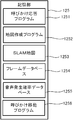
記憶部125は、ハードディスクドライブ、フラッシュメモリ等を含み、胴体120の内部に設けられている。記憶部125は、後述の制御部127によって実行されるプログラム、カメラ111が撮像した画像データ等を含む各種データを記憶する。記憶部125が記憶するプログラムには、後述の呼びかけ応答処理に係る呼びかけ応答プログラム1251、地図作成処理に係る地図作成プログラム1252が含まれる。さらに、記憶部125には、後述のSLAM(Simultaneous Localization And Mapping)法で作成される部屋の地図であるSLAM地図1253、撮像画像の特徴点等を格納するフレームデータベース1254、後述のラベリングの音声発生確率が定義された音声発生確率データベース1255が含まれる。
The
足回り部126は、胴体120の下側に設けられた4つの車輪(ホイール)を含む。図1に示すように、4つの車輪のうち、2つが胴体120の前側に、残り2つが後ろ側に(不図示)が配置されている。車輪として、例えば、オムニホイール、メカナムホイールが使用される。後述の制御部127が足回り部126の車輪を回転させると、ロボット100は移動する。足回り部126は、前述の首関節121とともに、後述の制御部127と協働して、ロボット100の各部位の動作を制御することで、自機の位置、姿勢の少なくとも一方を変える制御手段としての役割を果たす。
The
さらに、足回り部126の車輪にはロータリエンコーダが設けられている。ロータリエンコーダで車輪の回転数を計測し、車輪の直径や車輪間の距離等の幾何学的関係を利用することで並進移動量及び回転量を計算できる。
Further, a rotary encoder is provided on the wheels of the
図3を参照する。制御部127は、CPU(Central Processing Unit)、RAM(Random Access Memory)等で構成される。制御部127は、上述のロボット100の各部に接続されており、RAMをワークスペースとして、記憶部125に記憶されたプログラムを実行することにより、ロボット100の各部を制御する。
Please refer to FIG. The
本実施の形態においては、制御部127は、ロボット100の各部位の動作を制御するため、前述の首関節121、足回り部126を制御することで、自機の位置、姿勢の少なくとも一方を変える制御手段の役割を果たす。
In the present embodiment, the
さらに、制御部127は、足回り部126の車輪に設けられたロータリエンコーダの回転数から、自機の位置(移動開始時の位置を基準とした自機の位置)を計測することができる。例えば、車輪の直径をD、回転数をR(足回り部126のロータリエンコーダにより測定)とすると、その車輪の接地部分での並進移動量はπ・D・Rとなる。また、車輪の直径をD、車輪間の距離をI、右車輪の回転数をRR、左車輪の回転数をRLとすると、向き変更の回転量は(右回転を正とすると)360°×D×(RL−RR)/(2×I)となる。この並進移動量や回転量を逐次足し合わせていくことで、自機位置(移動開始時の位置及び向きを基準とした位置及び向き)を計測することができる。このように、制御部127は、オドメトリとしても機能する。
Further, the
上述のように、ロボット100は、住人(ユーザ)に呼びかけられると会話するので、呼びかけられたことを判別すると、呼びかけた住人(ユーザ)の顔検出を行う必要がある。以下、ロボット100が行う顔検出の処理を説明する。ここでは、ユーザの呼びかけに応答する一連の処理(呼びかけ応答処理)の中で、ロボット100がユーザの顔検出を行う例を説明する。図4に示すように、部屋RM内にロボット100とユーザPがおり、ロボット100とユーザPとが正対していない場合に、ユーザPがロボット100に呼びかける場面を想定する。
As described above, since the
本実施の形態においては、部屋RM内に存在する音源の位置が登録された地図(音声発生源位置情報)があらかじめ作成されている。ロボット100の制御部127は、人の声がしたことを検出したときに、まず、その音の音源の方向を判別する。そして、制御部127は、音源の方向と自機(ロボット100)の位置とあらかじめ作成されている部屋RMの中の地図とに基づき、判別した音源の方向に、人以外の音源が存在するか否かを判別し、存在する否かに応じて、振り向くか振り向かないかを判別する。
In the present embodiment, a map (sound source position information) in which the positions of sound sources existing in the room RM are registered is created in advance. When detecting that a human voice is heard, the
呼びかけ応答処理に先立ってあらかじめ作成される実空間(ここでは部屋RM)内の地図の作成方法を説明する。制御部127の制御の下、ロボット100は、毎日決められた時刻に、部屋の中を動き回りながら、撮像し、撮像画像に基づいて部屋の地図を作成し、作成した地図を記憶部125に格納する。
A method of creating a map in a real space (here, room RM) created in advance prior to the call response process will be described. Under the control of the
地図の作成には、SLAM法を採用する。SLAM法は、実空間の地図を作成するための手法のひとつである。この手法では、カメラの撮影する動画像の複数フレームから、同一の特徴点を追跡することで、自機の3次元位置(カメラ位置)と特徴点の3次元位置(これが集まって地図の情報を構成する)とを交互または同時に推定する処理を行う。SLAM法の詳細は、非特許文献1に記載されている。
The SLAM method is used to create the map. The SLAM method is one of the methods for creating a map of a real space. In this method, the same feature point is tracked from a plurality of frames of a moving image captured by a camera, and the three-dimensional position of the own device (camera position) and the three-dimensional position of the feature point (this is collected to obtain map information. ) Is alternately or simultaneously performed. Details of the SLAM method are described in
以下、図5のフローチャートを参照しながら、制御部127が行うSLAM法を採用した地図作成処理を説明する。制御部127は、記憶部125に記憶されている地図作成プログラム1252を実行することによって、以下の処理を実現する。
Hereinafter, the map creation processing adopting the SLAM method performed by the
まず、制御部127は、撮像画像を取得し、撮像画像の二次元特徴点(2D特徴点)を抽出する(ステップS11)。2D特徴点とは、画像中のエッジ部分など、画像内の特徴的な部分であり、SIFT(Scale-Invariant Feature Transform)やSURF(Speed-Up Robust Features)等のアルゴリズムを用いて取得することができる。
First, the
具体的には、ステップS11において、制御部127は、カメラ111を制御して、撮像を行う。そして、撮像した画像から2D特徴点を抽出する。さらに、前述のようにオドメトリとしても機能する制御部127は、足回り部126のロータリエンコーダを使用して、自機(ロボット100)の現在位置を計測する。制御部127は、2D特徴点と、自機の現在位置と、を撮像画像と対応づけて記憶部125に記憶する。
Specifically, in step S11, the
制御部127は、地図作成処理の開始後に撮像した画像が2枚以上であるか否かを判別する(ステップS12)。2枚未満であると判別すると、(ステップS12;Nо)、制御部127は、足回り部126を制御して、自機を所定の距離だけ移動し(ステップS19)、再びステップS11へ戻る。
The
一方、撮像した画像が2枚以上であると判別した場合(ステップS12;Yes)、制御部127は、2つの画像の2D特徴点の対応を取得する(ステップS13)。2つの画像は、例えば、今回撮像した画像と、直近に撮像した画像である。
On the other hand, when it is determined that the number of captured images is two or more (Step S12; Yes), the
ステップS13で取得した2つの画像の対応する特徴点(対応特徴点)の個数が、閾値未満であるか否かを判別する(ステップS14)。これは、取得した特徴点の個数が少ないと、後述のTwo−view Structure from Motion法での計算ができないためである。 It is determined whether or not the number of corresponding feature points (corresponding feature points) of the two images acquired in step S13 is less than a threshold (step S14). This is because if the number of acquired feature points is small, calculation by the two-view structure from motion method described later cannot be performed.
2つの画像の対応する特徴点の個数が、閾値未満であると判別した場合(ステップS14;No)、制御部127は、足回り部126を制御して、自機を所定の距離だけ移動し(ステップS19)、再びステップS11へ戻る。
When it is determined that the number of corresponding feature points of the two images is less than the threshold value (Step S14; No), the
一方、2つの画像の対応する特徴点の個数が、閾値以上であると判別した場合(ステップS14;Yes)、制御部127は、2つの画像間の姿勢を推定する(ステップS15)。
On the other hand, when it is determined that the number of corresponding feature points of the two images is equal to or larger than the threshold value (Step S14; Yes), the
具体的には、ステップS15において、Two−view Structure from Motion法を用いて、2つの画像の間で対応する2D特徴点の2次元座標(2D座標)と、2つの画像のそれぞれの撮影位置(撮影時の自機の位置)の間の距離とから、2つの画像間の姿勢(それぞれの画像を取得した位置の差分(並進ベクトルt)及び向きの差分(回転行列R))を推定する。この推定は、非特許文献2に記載されているように、エピポーラ拘束式により、対応する特徴点から基礎行列Eを求め、基礎行列Eを並進ベクトルtと回転行列Rとに分解することによって得られる。 Specifically, in step S15, the two-dimensional coordinates (2D coordinates) of the corresponding 2D feature point between the two images and the shooting positions (2D coordinates) of the two images using the two-view structure from motion method. The posture between the two images (the difference between the positions at which the images were acquired (translation vector t) and the difference between the orientations (rotation matrix R)) is estimated from the distance between the images (the position of the own device at the time of shooting). As described in Non-Patent Document 2, this estimation is obtained by finding a fundamental matrix E from corresponding feature points by an epipolar constraint formula, and decomposing the fundamental matrix E into a translation vector t and a rotation matrix R. Can be
続いて、制御部127は、2つの画像の間で対応する2D特徴点(2Dの対応特徴点)の3次元座標(3D座標)を推定する(ステップS16)。具体的には、これは、ステップS15で算出した2つの画像間の姿勢を表す値と、2つの画像の間で対応する2D特徴点の2D座標と、を用いて推定する。
Subsequently, the
制御部127は、ステップS16で推定した推定値をデータベースに登録する(ステップS17)。具体的には、制御部127は、ステップS16で求めた「2Dの対応特徴点の3D座標(X、Y、Z)」と、「2D特徴点の特徴量」(例えばSIFT等で得た特徴量)と、を記憶部125のSLAM地図1253に登録する。
The
また、制御部127は、記憶部125のフレームデータベース1254に、画像の情報として、「SLAM地図内での画像の姿勢」(その画像を撮像したときの自機のSLAM座標内での位置(並進ベクトルt)及び向き(回転行列R))と、「抽出した全ての2D特徴点」と、「すべての2D特徴点の中で3D位置(3D座標)が既知の点」と、「キーフレーム自体の特徴」と、を記憶部125のフレームデータベース1254に登録する。
In addition, the
ここで、キーフレームとは、処理の対象となる撮像画像のことである。キーフレーム自体の特徴とは、キーフレーム間の画像類似度を求める処理を効率化するためのデータであり、画像中の2D特徴点のヒストグラム等を用いてもよいし、画像自体を「キーフレーム自体の特徴」としてもよい。 Here, the key frame is a captured image to be processed. The feature of the key frame itself is data for increasing the efficiency of the process of obtaining the image similarity between the key frames. For example, a histogram of 2D feature points in the image may be used. It may be a feature of itself.
制御部127は、処理が終了であると判別すると(ステップS18;Yes)、地図作成処理を終了する。一方、処理が終了でないと判別すると(ステップS18;No)、足回り部126を制御して、自機を所定の距離だけ移動し(ステップS19)、再びステップS11へ戻る。以上が地図作成処理である。
When the
さらに、上述のように作成したSLAM地図1253に、部屋RM内のそれぞれの位置における障害物が存在する確率を示す障害物情報として確率変数を付加してもよい。障害物情報の確率変数の値は、その値が高いほど、その位置に障害物がある可能性が高いことを表している。障害物情報の確率変数は、例えば、SLAM地図1253の作成処理におけるデータベース登録(図5のステップS17)のタイミングで、SLAM地図1253に付加することができる。
Further, a probability variable may be added to the
さらに、本実施の形態においては、上述のように作成したSLAM地図1253に、人以外の音声発生源情報を付加したものを使用して、ロボット100が、検出した音が人であるか否かを判別する。
Furthermore, in the present embodiment, using the
人以外の音声発生源情報は、例えば、SLAM地図1253の作成処理におけるデータベース登録(図5のステップS17)のタイミングで、SLAM地図1253に付加することができる。
The voice source information other than the person can be added to the
音声発生源の特定は、例えば以下のような方法で行う。SLAM地図1253の作成時にロボット100が部屋RM内を動き回り撮像した画像に対して、一般画像認識(画像に含まれる物体を一般的な名称で認識する処理)を行い、音声発生源か否かのラベリングする方法を用いてもよい。画像内で音声発生源としてラベリングされた領域に存在する2D特徴点に対応する地図内の地点に対して第1の値(第2の値より大きい値)を登録する。また、それ以外の2D特徴点に対応する地点には、第2の値(第1の値より小さい値)を登録する。具体的には、ロボット100が通過した地点には、第2の値を登録し、ロボット100が通過した際に、接触センサ、距離センサ等により障害物に接触したと判別した地点には、第1の値を登録する。
The sound source is specified, for example, by the following method. At the time of creating the
上述の例では、確率変数を2値とすることを説明した。あるいは、一般画像認識結果の尤度に、ラベリングの音声発生確率を乗じた値を確率変数としてもよい。 In the above-described example, it has been described that the random variable is binary. Alternatively, a value obtained by multiplying the likelihood of the general image recognition result by the occurrence probability of the labeling sound may be used as the probability variable.
ラベリングの音声発生確率、ここでは、部屋RM内のそれぞれの位置における音声発生源の確率を示す情報(確率変数)はあらかじめ記憶部125の音声発生確率データベース1255に登録されているものとする。確率変数の値は、値が高いほど、当該位置に人以外の音声発生源が存在する可能性が高いことを示す。
It is assumed that information (probability variables) indicating the probability of the sound source at each position in the room RM is registered in the sound
音声発生確率データベース1255に登録されているラベリングの音声発生確率として、例えば、換気扇:0.8、ドア:0.5、観葉植物:0といった値が登録されている。換気扇は、動作中にそれなりの音を出し、ドアは、開け閉めする人により出る音の大きさに差があり、置かれているだけの観葉植物については、音は発生しないといった観点で、このような値が規定される。
For example, values such as a ventilator: 0.8, a door: 0.5, and a houseplant: 0 are registered as the labeling sound occurrence probabilities registered in the sound
また、ラベリングの音声発生確率は、時刻、季節、気温等に応じて、複数の値を規定しておいてもよい。季節に応じたラベリングの場合、例えば、夏:0.8、冬:0とする。夏場であれば、窓を開けることが多いため、室内でも室外で発生した音が聞こえることがあり、冬場の窓を閉め切った状態であれば、室外の音はほぼ聴こえないからである。 In addition, a plurality of values may be defined as the labeling sound generation probability according to time, season, temperature, and the like. In the case of labeling according to the season, for example, summer: 0.8 and winter: 0. This is because in summer, windows are often opened, so that sounds generated outdoors can be heard even indoors, and when the windows are closed in winter, almost no sounds outside can be heard.
また、一般画像認識結果の尤度を使用するのは次のような理由による。一般画像認識を使用した場合、どのような画像に対しても、認識の精度が高いというわけではない。一般画像認識結果の尤度を用いることで、一般画像認識が誤認識した場合の影響を減らすことができる。 The reason for using the likelihood of the general image recognition result is as follows. When general image recognition is used, the accuracy of recognition is not high for every image. By using the likelihood of the general image recognition result, it is possible to reduce the influence of erroneous general image recognition.
また、一般画像認識ではなく他の手法を用いてもよい。非特許文献3に記載されているBag-of-featuresという手法がある。この手法は、画像中の物体がどのカテゴリに属するかを求める画像分類問題の手法である。 Also, other methods may be used instead of the general image recognition. There is a method called Bag-of-features described in Non-Patent Document 3. This method is a method of an image classification problem for determining which category an object in an image belongs to.
あるいは、一般画像認識ではなく、ユーザが指定した音声発生源の領域、音声発生源となる物体を示す情報を、作成したSLAM地図1253に追加してもよい。この場合、例えば、ロボット100は、タッチパネル、ディスプレイ等の表示装置と、タッチパネル、キーボード等の入力装置を備え、ユーザに対して作成したSLAM地図1253を提示して、ユーザに音声発生源を入力されるようにしてもよい。
Alternatively, instead of general image recognition, information indicating an area of a sound source designated by a user and an object serving as a sound source may be added to the created
あるいは、ロボット100は、SLAM地図1253後に、部屋R内を動き回り、部屋RM内にある物体を指さしして、ユーザに、当該物体が音声発生源であるか等を尋ねてもよい。ユーザの回答に基づく音声発生源の情報を、SLAM地図1253に追加することができる。
Alternatively, the
あるいは、SLAM地図1253後に、部屋RM内の物体を撮像し、撮像画像を表示装置に表示し、ユーザに、当該物体が音声発生源であるか等を尋ねてもよい。この場合も、ユーザの回答に基づく音声発生源の情報を、SLAM地図1253に追加することができる。
Alternatively, an object in the room RM may be imaged after the
次に、音を検出した場合に、地図を使用して、検出した音の音源が人であるか否かを判別し、判別結果に応じて応答する呼びかけ応答処理を説明する。呼びかけ応答処理の開始に先立って、上述の地図作成処理はすでに実行されているものとし、SLAM地図1253、フレームデータベース1254、音声発生確率データベース1255には、適宜の情報が登録済みであるとする。
Next, a description will be given of a call response process of determining whether or not the sound source of the detected sound is a human when a sound is detected, using a map, and responding according to the determination result. Prior to the start of the call response process, it is assumed that the above-described map creation process has already been executed, and that appropriate information has been registered in the
制御部127は、記憶部125の呼びかけ応答プログラム1251を実行することで、以下の呼びかけ応答処理を行い、検出した音声発生源が特定の音声発生源(ここでは人間)であるか否かを判別する判別手段として機能する。
The
図6のフローチャートを参照しながら、呼びかけ応答処理を説明する。制御部127は、ロボット100の周辺である程度の大きさの音を検出したか否かを判別する(ステップS101)。具体的には、制御部127は、1つ以上のマイク112に所定の閾値以上の振幅の音が入力されたか否かを判別する。なお、所定の大きさとは、マイク112の感度によるものとする。
The call response process will be described with reference to the flowchart of FIG. The
マイク112により所定の大きさの音が検出できない場合(ステップS101;No)、制御部127は、音を検出するまで待ち受ける。
When a sound of a predetermined volume cannot be detected by the microphone 112 (Step S101; No), the
一方、ある程度の大きさの音を検出したと判別した場合(ステップS101;Yes)、制御部127は、マイク112により検出した音が人間の声か否かを判別する(ステップS102)。具体的には、制御部127は、ステップS101で検出した音が特定の周波数帯域の音であるか否かを判別する。ステップS101で検出した音が人間の声でない場合(ステップS102;No)、制御部127はステップS101へ戻り、音を検出するまで待ち受ける。
On the other hand, when it is determined that a sound of a certain volume has been detected (Step S101; Yes), the
一方、人間の声であると判別すると(ステップS102;Yes)、制御部127は、音源の位置(ここではユーザPの声が発せられた位置)を求めるため、音声定位を行う(ステップS103)。ここでは、音源の位置を推定するため、音源定位のひとつの手法であるMUSIC(MUltiple SIgnal Classification)を採用することとする。なお、音源定位の最中に音源であるユーザPは移動せず、静止しているものとする。
On the other hand, if it is determined that the voice is a human voice (Step S102; Yes), the
図7を参照して音源定位を説明する。まず、マイク112に入力された音声を時間周波数変換する(ステップS10301)。ここでは、時間周波数変換として、STFT(Short−Time Fourier Transform)(短時間フーリエ変換)を行う。
The sound source localization will be described with reference to FIG. First, the sound input to the
音源数をNとすると、第n番目の音源の信号Snは、下記式(1)で表せる。
Sn(ω,f)(n=1,2,…,N) …(1)
ωは角周波数、fはフレーム番号である(以下の説明でも同様)。
When the number of sound sources is N, the signal S n of the n-th sound source can be expressed by the following formula (1).
S n (ω, f) (n = 1, 2,..., N) (1)
ω is an angular frequency, and f is a frame number (the same applies to the following description).
マイク112で観測される信号は、マイク112の数をMとすると、下記式(2)で表せる。
Xm(ω,f)(m=1,2,…,M) …(2)
The signal observed by the
X m (ω, f) (m = 1, 2,..., M) (2)
音源から出た音は、空気を伝わってマイク112で観測されるが、そのときの伝達関数をHnm(ω)とすると、音源の信号を表す数式に、伝達関数を乗じることで、マイク112で観測される信号を求めることができる。m番目のマイク112で観測される信号Xm(ω,f)は下記式(3)のように表される。
The sound emitted from the sound source travels through the air and is observed by the

ロボット100は、マイク112を複数有しているので、マイク112全体で観測される信号x(ω,f)は下記式(4)で表すことができる。
Since the
同様に、全音源の信号s(ω,f)も下記式(5)で表すことができる。 Similarly, the signals s (ω, f) of all the sound sources can be expressed by the following equation (5).
同様に、第n番目の音源の伝達関数hn(ω)は下記式(6)で表すことができる。 Similarly, the transfer function h n of the n-th sound source (omega) can be represented by the following formula (6).
全ての伝達関数を下記式(7)のように表記する。
h(ω)=[h1(ω),h2(ω),…hN(ω)] …(7)
All transfer functions are expressed as in the following equation (7).
h (ω) = [h 1 (ω), h 2 (ω),... h N (ω)] (7)
上記の式(7)で表される伝達関数を、上述の式(3)に適用すると、下記式(8)のように表される。
x(ω,f)=h(ω)s(ω,f) …(8)
When the transfer function represented by the above equation (7) is applied to the above equation (3), the transfer function is represented by the following equation (8).
x (ω, f) = h (ω) s (ω, f) (8)
hn(ω)は音源位置毎に独立であり、ある程度のフレーム数(例えば、フレーム数をLとする))で見ればSn(ω,f)は無相関とみなせるので、x(ω,f)は音源数NをRANKとする超平面を構成する。このとき、距離で正規化した音量が大きな音源の伝達関数方向に分布が広がりやすい。そこで、部分空間とゼロ空間に分解することを考える。 h n (ω) is independent for each sound source position, and when viewed from a certain number of frames (for example, the number of frames is L), S n (ω, f) can be regarded as uncorrelated. f) forms a hyperplane with the number of sound sources N as RANK. At this time, the distribution tends to spread in the direction of the transfer function of the sound source having a large volume normalized by the distance. Then, it is considered to decompose into a subspace and a zero space.
再び図7を参照する。次の式(9)に示すように相関行列を計算する(ステップS10302)。ここで、*は複素共役転置を意味する。 FIG. 7 is referred to again. A correlation matrix is calculated as shown in the following equation (9) (step S10302). Here, * means complex conjugate transpose.
続いて、固有値分解する(ステップS10303)。ここで、固有値λm(ω,f)と固有ベクトルem(ω,f)は固有値が降順になるように並べ替えられているものとする。 Subsequently, eigenvalue decomposition is performed (step S10303). Here, it is assumed that the eigenvalue λm (ω, f) and the eigenvector em (ω, f) are rearranged such that the eigenvalues are in descending order.
原理的には、hn(ω)は部分空間の固有ベクトルem(ω,f)(m=1〜N)の重み付け加算から復元できるが、実際には復元が困難であるためゼロ空間を構成する固有ベクトルem(ω,f)(m=N+1〜M)がhn(ω)と直交することを使って音源定位を実現する。 In principle, h n (ω) can be restored from the weighted addition of the eigenvectors em (ω, f) (m = 1 to N) of the subspace, but actually, it is difficult to restore, and thus constitutes a zero space. The sound source localization is realized by using the fact that the eigenvector em (ω, f) (m = N + 1 to M) is orthogonal to h n (ω).
しかし、音源であるユーザPが部屋RM内を移動する可能性があるため、音源位置を予め知ることはできず、音源位置の伝達関数を予め取得しておくことは難しい。このため、仮の音源位置を決め、仮の音源位置の伝達関数をあらかじめ用意しておき、音源定位を行う。 However, since the user P as the sound source may move in the room RM, the position of the sound source cannot be known in advance, and it is difficult to acquire the transfer function of the sound source position in advance. Therefore, a temporary sound source position is determined, a transfer function of the temporary sound source position is prepared in advance, and the sound source localization is performed.
図8に、仮の音源位置とマイクの配置の一例を示す。図8では、太線の円がロボット100の頭110を表し、太線上の黒丸がマイク112を表す。なお、ここでは、便宜上13個のマイク112の全てを表示していない。ロボット100の回りには4個の仮の音源位置があるものとする。
FIG. 8 shows an example of a provisional sound source position and microphone arrangement. In FIG. 8, a bold circle represents the
複数のマイク112は、ロボット100の頭110に配置されていることから、円周に沿って配置されているとみなすことができる。X軸の正の向きと、マイク112が成す円の中心(ロボット100の頭110の中心位置に相当)と仮の音源1〜4とをそれぞれ結んだ線と、がなす角度をθ1、θ2、θ3、θ4とし、それぞれの伝達関数hθ(ω)を予め計算しておく。
Since the plurality of
図8では、音源が4個の例を示したが、音源数がN個の場合、θ1、θ2、…θNのそれぞれの伝達関数hθ(ω)を予め計算しておけばよい。また、あるいは、仮の音源位置の伝達関数を用意するのではなく、幾何的な情報をもとに予め伝達関数を計算しておいてもよい。 FIG. 8 shows an example in which the number of sound sources is four, but when the number of sound sources is N, transfer functions h θ (ω) of θ1, θ2,..., ΘN may be calculated in advance. Alternatively, instead of preparing a transfer function of a temporary sound source position, a transfer function may be calculated in advance based on geometric information.
再び図7を参照する。次の式(10)を使用して、周波数帯毎のMUSICスペクトルを計算する(ステップS10304)。 FIG. 7 is referred to again. The MUSIC spectrum for each frequency band is calculated using the following equation (10) (step S10304).
ここで、式(10)の分母は、ノイズや誤差、STFTの周波数帯間の信号漏洩の影響等からゼロにはならない。また、音源の方向とあらかじめ決めた角度θ(θ1、θ2、…θN)のいずれかが近い場合、つまりhn(ω)とhθ(ω)が近い場合、式(10)の値は極端に大きなものになる。図8に示す例では、音源である人と仮の音源2の位置が近いため、θ2の伝達関数を使用した場合、式(10)の値が極端に大きくなることが想定される。 Here, the denominator of the equation (10) does not become zero due to noise and error, influence of signal leakage between frequency bands of the STFT, and the like. When the direction of the sound source is close to one of the predetermined angles θ (θ1, θ2,..., ΘN), that is, when h n (ω) and h θ (ω) are close, the value of equation (10) is extremely Will be bigger. In the example shown in FIG. 8, since the position of the temporary sound source 2 is close to that of the sound source, when the transfer function of θ2 is used, it is assumed that the value of Expression (10) becomes extremely large.
そして、統合したMUSICのパワーを求めるため、式(11)に示すように周波数帯毎のMUSICスペクトルを重み付け加算する(ステップS10305)。 Then, in order to obtain the power of the integrated MUSIC, the MUSIC spectrum for each frequency band is weighted and added as shown in Expression (11) (step S10305).
重み付け係数は、固有値λm(ω,f)が大きいほど大きくすれば、Sn(ω,f)に含まれるパワーに応じた計算をすることもできる。この場合はSn(ω,f)に殆どパワーがない場合の悪影響を軽減できる。 If the weighting coefficient increases as the eigenvalue λm (ω, f) increases, it is also possible to calculate according to the power included in S n (ω, f). In this case, it is possible to reduce the adverse effect when S n (ω, f) has almost no power.
続いて、パワースペクトルから適切なピーク(極大値)を選択する(ステップS10306)。具体的には、まず、複数のピークを求め、その中から適切なピークを選択し、選択したピークにおけるθを音源方向とする。ここで、ピークを求めるのは以下のような理由による。本来の音源方向のθのパワーが必ずしも一番大きいとは限らず、本来の音源方向に近いθのパワーは総じて大きくなるので、音源方向は複数のピークの何れかに正解があるからである。 Subsequently, an appropriate peak (maximum value) is selected from the power spectrum (step S10306). Specifically, first, a plurality of peaks are obtained, an appropriate peak is selected from the peaks, and θ at the selected peak is set as the sound source direction. Here, the peak is determined for the following reason. This is because the power of θ in the original sound source direction is not always the largest, and the power of θ close to the original sound source direction generally increases, so that the sound source direction has a correct answer at any of a plurality of peaks.
また、テレビが点いている、ドアホンが鳴る等の部屋RM内に他の音源がある場合でも、多くの場合、人は、テレビ、ドアホン等の周囲の音より大きな声でロボット100に呼びかけると考えられる。よって、人の声のパワーの方が、人以外のテレビ、ドアホン等の音源から発せられる音のパワーより大きくなることが想定される。よって、単純にパワーが最大となる仮の音源位置を示すθを音源方向として選択しても問題はない。ただし、周囲の環境などによっては、パワーが最大となる仮の音源位置ではなく、パワーが2番目あるいはそれ以降となる仮の音源位置を、音源方向と選択することが適切な場合もある。このようにして、制御部127は、音源方向、ここでは、ロボット100の位置から見たユーザPがいる方向、を判別することができる。
In addition, even when there is another sound source in the room RM such as when a TV is on or a door phone sounds, in many cases, it is considered that a person calls the
音源定位の処理は以上である。ここでは、平面を仮定して説明したが、3次元を仮定しても上記説明は成り立つ。 This is the end of the sound source localization processing. Here, the description has been made assuming a plane, but the above description holds even if it is assumed to be three-dimensional.
再び図6を参照する。ステップS103の音源定位を実行して音源方向を判別すると、制御部127は、音源方向を示す情報として、ロボット100の向いている方向に対する音源の方向を示す角度θを記憶部125に記憶する。続いて、制御部127は、ステップS104へ進み、撮影画像と、地図(SLAM地図1253、フレームデータベース1254)を用いて自機位置推定の処理を実行する。
FIG. 6 is referred to again. When the sound source direction is determined by executing the sound source localization in step S103, the
図9を参照して、自機位置の推定の処理を説明する。制御部127は、カメラ111により撮像された画像の二次元特徴点(2D特徴点)を抽出する(ステップS10401)。具体的には、制御部127は、カメラ111を制御して撮像し、撮像した画像から2D特徴点を抽出する。
The process of estimating the position of the own device will be described with reference to FIG. The
続いて、制御部127は、記憶部125のフレームデータベース1254を参照して、フレームデータベース1254に登録されている以前のフレームの情報から、その画像の情報に含まれている2D特徴点のうち、3D位置が既知である2D特徴点を取得し、取得した2D特徴点から、ステップS10401で抽出した2D特徴点と、対応が取れる特徴点を抽出する(ステップS10402)。ここで、3D位置が既知であるとは、即ち、2D特徴点がSLAM地図に登録されていることを意味する。
Subsequently, the
制御部127は、ステップS10402で抽出した対応が取れる特徴点の個数が、閾値以上であるか否かを判別する(ステップS10403)。閾値未満であると判別した場合(ステップS10403;No)、制御部127は、足回り部126を制御して、自機を所定の距離だけ移動し(ステップS10406)、再びステップS10401へ戻る。
The
一方、ステップS10402で抽出した対応特徴点の個数が、閾値以上であると判別した場合(ステップS10403;Yes)、制御部127は、記憶部125のSLAM地図1253から、ステップS10402で抽出した対応特徴点それぞれの3D座標(Xi,Yi,Zi)を取得する(ステップS10404)。
On the other hand, if it is determined that the number of corresponding feature points extracted in step S10402 is equal to or larger than the threshold (step S10403; Yes), the
続いて、制御部127は、自機の姿勢を推定する(ステップS10405)。ここでは、制御部127は、対応特徴点のSLAM地図上の3D位置と、対応特徴点のフレーム座標(2D座標)の関係から自機の姿勢(並進ベクトルt及び回転行列Rで表される自機の位置及び向き)を推定する。
Subsequently, the
具体的には、今撮像した画像に含まれている対応特徴点のフレーム座標を(ui,vi)とし、その対応特徴点の3D座標を(Xi,Yi,Zi)とする(iは1から対応特徴点の数までの値を取る)。ここで、各対応特徴点の3D位置(Xi,Yi,Zi)を下記式(12)によってフレーム座標系に投影した値(uxi,vxi)とフレーム座標(ui,vi)とは理想的には一致する。
(uxi vxi 1)’〜A(R|t)(Xi Yi Zi 1)’ …(12)
Specifically, the frame coordinates of the corresponding feature point included in the image just captured are set to (ui, vi), and the 3D coordinates of the corresponding feature point are set to (Xi, Yi, Zi) (i is 1 to 1). Take values up to the number of corresponding feature points). Here, the values (uxi, vxi) and the frame coordinates (ui, vi) obtained by projecting the 3D position (Xi, Yi, Zi) of each corresponding feature point on the frame coordinate system by the following equation (12) are ideally obtained. Matches.
(Uxi vxi 1) ′-A (R | t) (Xi Yi Zi 1) ′ (12)
しかし、実際には(Xi,Yi,Zi)にも(ui,vi)にも誤差が含まれているため、(uxi,vxi)と(ui,vi)とが一致することはめったにない。そして、未知数はRとt(3次元空間ではそれぞれ3次元となり、3+3=6が未知数の個数である)だけなのに、数式は対応特徴点の個数の2倍存在する(対応特徴点一つに対して、フレーム座標のu,vそれぞれに対する式が存在するため)ことになるため、過剰条件の連立一次方程式になり、上述したように最小二乗法で求めることになる。 However, since (Xi, Yi, Zi) and (ui, vi) actually contain an error, (uxi, vxi) and (ui, vi) rarely coincide with each other. Although the unknowns are only R and t (three-dimensional in a three-dimensional space, and 3 + 3 = 6 is the number of unknowns), the mathematical expression exists twice as many as the number of corresponding feature points (one corresponding feature point). Therefore, since there is an equation for each of u and v of the frame coordinates), it becomes a simultaneous linear equation with excess conditions, and is obtained by the least square method as described above.
具体的には、制御部127は、以下の式(13)のコスト関数E1を最小化する姿勢(並進ベクトルt及び回転行列R)を求める。
Specifically, the
このように求めた値が、SLAM法で求めたSLAM座標での自機の姿勢(並進ベクトルt及び回転行列Rで表される自機の位置及び向き)を示す値である。このようにして算出した値により自機の姿勢が推定される。以上が自機位置推定の処理である。 The value thus obtained is a value indicating the attitude of the own device (the position and orientation of the own device represented by the translation vector t and the rotation matrix R) at the SLAM coordinates obtained by the SLAM method. The attitude of the own device is estimated from the value calculated in this way. The above is the process of estimating the position of the own device.
再び、図6を参照する。制御部127は、ステップS104の自機位置の推定の処理が終わると、ステップS105へ進み、SLAM地図1253と音声発生確率データベース1255とを参照して、ステップS104で推定した自機位置から、ステップS103で求めた音源方向に、人以外の音声発生源が存在する確率を取得する(ステップS105)。ここでは、音源方向の各点の確率の平均を求め、求めた平均を人以外の音声発生源が存在する確率としてもよい。あるいは、音源方向の各点の確率について最大値を人以外の音声発生源が存在する確率としてもよい。
FIG. 6 is referred to again. When the processing of estimating the position of the own device in step S104 ends, the
次に、制御部127は、ステップS105で求めた人以外の音声発生源が存在する確率が閾値以上であるか否かを判別する(ステップS106)。人以外の音声発生源が存在する確率が閾値以上であると判別した場合(ステップS106;Yes)、制御部127は、音源方向の音源は人以外であると判別して、首関節121を回転駆動させず、再びステップS101へ戻り、音の入力を待ち受ける。
Next, the
一方、人以外の音声発生源が存在する確率が閾値未満であると判別した場合(ステップS106;No)、制御部127は、ステップS107へ進む。
On the other hand, when it is determined that the probability that a voice source other than a person exists is less than the threshold (step S106; No), the
続いて制御部127は、頭110の回転をさせるため、首関節121を回転駆動させる(ステップS107)。ここで、制御部127は、ロボット100の頭110の正面(カメラ111のレンズ面)が音源(ユーザP)の方向に向くまで、頭110を回転する。具体的には、制御部127は、記憶部125に記憶されている音源定位により求められた角度θに基づいて、求めた角度だけ頭110を回転し、その後、回転駆動を停止する。このようにして、カメラ111のレンズ面を音源(ユーザP)がいる方向に向ける。
Subsequently, the
回転駆動を停止した後、制御部127は、顔検出の処理を実行する(ステップS108)。まず、制御部127は、カメラ111を制御して撮像し、撮像した画像に対して以下の処理を施すことで、顔検出処理を実行する。
After stopping the rotation drive, the
制御部127は、まず、ピラミッド画像を作成する。ピラミッド画像とは、元画像を一定の比率で縮小を繰り返して作成した一連の画像群であり、ピラミッド画像の各階層に対して、固定サイズの顔検出器を適用することで様々なサイズ(つまり距離に相当)の顔を検出することができる。ここでは、回転によるカメラの見え方は対象までの距離によって変わるので、ピラミッド画像を使用して顔検出を行う。
The
まず、顔探索対象を最初の階層に設定する。ここでは縮小前の元の画像とする。最初の検出窓を設定する。初期位置は例えば左上の隅とする。設定した検出窓に対して、固定サイズの顔検出器を適用する。この階層でのスライドによる探索が完了したかを判定する。スライドによる探索が完了でないなら、検索窓をスライドさせ、再度顔検出を行う。スライドによる探索が完了ならば、ピラミッド画像のすべての階層での処理が完了したかの判定を行う。すべての階層での処理が完了でないなら、階層を移動し、移動先の階層でもスライドによる顔検出を行う。すべての階層での処理が完了したならば、顔検出の処理を終了する。 First, the face search target is set to the first hierarchy. Here, the original image before reduction is used. Set the first detection window. The initial position is, for example, the upper left corner. A fixed-size face detector is applied to the set detection window. It is determined whether the search by the slide at this level has been completed. If the search by the slide is not completed, the search window is slid and the face is detected again. If the search by the slide is completed, it is determined whether or not the processing in all the layers of the pyramid image has been completed. If the processing is not completed in all the hierarchies, the hierarchies are moved, and face detection by slide is performed in the destination hierarchy. When the processing at all the hierarchies is completed, the face detection processing ends.
なお、ロボット100から近い顔画像は、画角に入りきらない場合があることと、全体の計算負荷の割合が小さいことを考慮して、縮小率の大きい階層の顔探索はしないほうがより望ましい。
It should be noted that a face image close to the
顔検出処理により、撮像画像から顔を検出することができなかった場合(ステップS108;Nо)、制御部127は、再びステップS101に戻る。
When the face cannot be detected from the captured image by the face detection process (Step S108; No), the
一方、顔検出が成功すると(ステップS108;Yes)、続いて、制御部127は、ユーザPがロボット100に注目しているかどうかを判別する(ステップS109)。具体的には、制御部127は、カメラ111を制御して、ユーザPを撮像し、撮像した画像からユーザPの顔が、ロボット100の方を向いているか否かを判別する。ユーザPがロボット100に注目していないと判別すると(ステップS109;No)、再びステップS101へ戻り、音の入力を待ち受ける。
On the other hand, if the face detection is successful (Step S108; Yes), subsequently, the
一方、ユーザPの顔が、ロボット100の方を向いていると判別すると(ステップS109;Yes)、制御部127は、ユーザPに近づくように所定の距離だけ移動し(ステップS110)、ユーザPとの距離が決められた距離以下となったかを判別する(ステップS111)。このユーザPとロボット100との間の決められた距離は、ロボット100が、ユーザPが発声する内容を音声認識することができる程度の距離である。制御部127は、ロボット100とユーザPとの距離が決められた距離以下ではないと判別した場合に(ステップS111;No)。再びステップS110に戻る。
On the other hand, when determining that the face of the user P faces the robot 100 (Step S109; Yes), the
一方、制御部127は、ユーザPとの距離が所定の距離となったと判別した場合に(ステップS111;Yes)、ユーザPと対話する(ステップS112)。例えば、制御部127は、スピーカ113を制御して、ユーザPに対して、例えば、「何かご用ですか?」と話しかけ、また、マイク112から入力したユーザの発言を音声解析し、解析した内容に基づいて、なんらかの音声をスピーカ113から出力する。
On the other hand, when determining that the distance to the user P has reached the predetermined distance (Step S111; Yes), the
以上、説明したように、本実施の形態においては、ロボット100は、あらかじめ作成したSLAM地図1253に基づき、判別した音源方向に人以外の音源がある場合、人に呼ばれたのではないと判別する。よって、人以外の音源であるテレビ、ラジオ等から人の声が聞こえた場合であっても、振り向かないので、無駄な動作を減らすことができる。
As described above, in the present embodiment, the
なお、上述の説明においては、回転駆動はyawを前提で説明したが、他の方向の回転があっても成立する。 In the above description, the rotational drive has been described on the assumption of yaw.
実施の形態1においては、ロボット100は、ユーザPの方向へ近づくよう、単に移動したが、ロボット100は、SLAM地図1253を使用して、部屋RM内を移動し、ユーザに近づいてもよい。
In the first embodiment, the
(実施の形態2)
実施の形態2においては、ユーザPから呼びかけられたロボット100が、SLAM地図1253を使用して、移動経路を作成し、移動経路に沿って移動する。ロボット100が備える構成は、実施の形態1と同様である。以下の説明においては、実施の形態2に特有の構成を中心に説明する。
(Embodiment 2)
In the second embodiment, the
実施の形態1と同様に、あらかじめSLAM地図1253が作成されているものとする。
Assume that a
実施の形態2においては、図10に示すように、記憶部125には後述の呼びかけ移動処理のための呼びかけ移動プログラム1256が記憶されているものとする。制御部127は、呼びかけ移動プログラム1256を実行することによって、以下の処理を行う。
In the second embodiment, as shown in FIG. 10, it is assumed that the
図11にユーザPに呼びかけられたときに、ロボット100がユーザPのいる場所まで移動する処理(呼びかけ移動処理)のフローチャートを示す。なお、上述の呼びかけ応答処理と同様であるので、ここでは、所定の大きさの音を検出し、検出した音が人間の声であると判別したと仮定して、説明を行う。
FIG. 11 shows a flowchart of a process of moving the
制御部127は、撮像した画像とSLAM地図1253を用いて自機位置推定の処理を実行する(ステップS201)。自機位置推定の処理については図9を参照して説明したため、ここでは、説明を省略する。
The
続いて、制御部127は、SLAM法によるユーザPの顔の位置を推定する処理(顔位置推定の処理)を実行する(ステップS202)。図12を参照して、顔位置推定の処理を説明する。制御部127は、カメラ111を制御して撮像し、撮像した画像から二次元特徴点(2D特徴点)を抽出する(ステップS20201)。特徴抽出にはSIFTやSURF等のアルゴリズムを用いる。
Subsequently, the
制御部127は、ステップS20201で抽出した2D特徴点のうち、撮像した画像の顔の領域内の特徴点(2D顔特徴点)を抽出する(ステップS20202)。顔領域内に特徴点がない場合は、顔パーツ検出の結果を特徴点として用いる。
The
制御部127は、顔位置推定の処理開始後に撮像した画像が2枚以上であるか否かを判別する(ステップS20203)。2枚未満であると判別すると、(ステップS20203;Nо)、制御部127は、足回り部126を制御して、自機を所定の距離だけ移動し(ステップS20208)、再びステップS20201へ戻る。
The
一方、撮像した画像が2枚以上であると判別した場合(ステップS20203;Yes)、制御部127は、2つの画像の2D顔特徴点の対応を取得する(ステップS20204)。
On the other hand, if it is determined that the number of captured images is two or more (step S20203; Yes), the
制御部127は、ステップ20202で抽出した対応する2D顔特徴点の個数が、閾値以上であるか否かを判別する(ステップS20205)。閾値未満であると判別した場合(ステップS20205;No)、制御部127は、足回り部126を制御して、自機を所定の距離だけ移動し(ステップS20208)、再びステップS20201へ戻る。
The
一方、2つの画像の対応する2D顔特徴点の個数が、閾値以上であると判別した場合(ステップS20205;Yes)、制御部127は、2つの画像間の姿勢を推定する(ステップS20206)。
On the other hand, when it is determined that the number of the corresponding 2D face feature points of the two images is equal to or larger than the threshold value (step S20205; Yes), the
具体的には、2つの画像の間で対応する2D顔特徴点の2次元座標(2D座標)と、2つの画像のそれぞれの撮影位置(撮影時の自機の位置)の間の距離と、に対して、Two−view Structure from Motion法を用いて、2つの画像間の姿勢(それぞれの画像を取得した位置の差分(並進ベクトルt)及び向きの差分(回転行列R))を推定する。 Specifically, the two-dimensional coordinates (2D coordinates) of the corresponding 2D face feature point between the two images, the distance between the respective shooting positions of the two images (the position of the own device at the time of shooting), , The posture between the two images (the difference between the positions where the respective images are obtained (translation vector t) and the difference between the directions (rotation matrix R)) is estimated using the Two-View Structure from Motion method.
続いて、制御部127は、2つの画像の間で対応する2D顔特徴点の3次元座標(3D座標)を推定する(ステップS20207)。具体的には、これは、ステップS20206で算出した2つの画像間の姿勢を表す値と、2つの画像の間で対応する2D顔特徴点の2D座標と、を用いて推定する。以上が、顔位置推定の処理である。
Subsequently, the
図11を再び参照する。ステップS203に進み、制御部127は、自機位置からユーザPの顔位置までの経路の作成を行う(ステップS203)。
FIG. 11 is referred to again. Proceeding to step S203, the
実施の形態2においては、SLAM地図1253に、部屋RM内のそれぞれの位置における障害物が存在する確率を示す障害物情報の確率変数を付加したものを使用する。障害物情報の確率変数の値は、その値が高いほど、その位置に障害物がある可能性が高いことを表している。
In the second embodiment, a
経路の作成は、まず、記憶部125からSLAM地図1253を読み出し、SLAM地図1253上にランダムにノードを配置する(ノード情報を追加する)。このとき、自機(ロボット100)と同じ高さにノードを配置する。また、障害物情報の確率変数が閾値以上である位置(点)を中心とした一定の範囲内には、ノードを配置しない。
To create a route, first, the
なお、高さは、重力方向のオフセット値を用いて推定する。具体的には、ロボット100が過去に移動した位置から面推定を行い、法線ベクトル(重力方向)を求めて、自機位置と法線ベクトルの内積を求め自機位置の高さとする。経路中のノードも同様にして値を求める。自機位置の高さを表す値と、ノードの高さを表す値の差が決められた閾値以内であれば、自機位置の高さとノードの高さが同じであるとみなす。
The height is estimated using an offset value in the direction of gravity. Specifically, surface estimation is performed from the position where the
配置したノードについて、当該ノードを中心とした一定の範囲内に存在する他のノードとをつなぐ。これを、ランダムに配置した全てのノードについて行う。このようにして、グラフ構造を作る。 The arranged node is connected to another node existing within a certain range around the node. This is performed for all randomly arranged nodes. In this way, a graph structure is created.
ステップS201の自機位置推定で推定した自機の位置の一番近くに存在するノード、ステップS202顔位置推定で推定したユーザPの顔の一番近くに存在するノード、をそれぞれ選択する。そして、ダイクストラ法により、選択した2つのノード間の最短経路を求める。 A node existing closest to the position of the own device estimated by the own device position estimation in step S201 and a node existing closest to the face of the user P estimated by the face position estimation in step S202 are respectively selected. Then, the shortest path between the two selected nodes is obtained by Dijkstra's algorithm.
その後、求めた最短経路に従って、移動する(ステップS204)。以上が、実施の形態2にかかる呼びかけ移動処理である。 Thereafter, the user moves according to the obtained shortest route (step S204). The above is the call movement processing according to the second embodiment.
(変形例)
実施の形態2の呼びかけ移動処理では、2つの画像間の姿勢の推定(図12のステップS20206)に、Two−view Structure from Motion法を用いた。姿勢の推定はこれに限られない。
(Modification)
In the interrogation movement process of the second embodiment, the Two-view Structure from Motion method is used for estimating the posture between two images (step S20206 in FIG. 12). The estimation of the posture is not limited to this.
上述の自機位置推定の処理における姿勢の推定(図9のステップS10405)で行ったように姿勢を推定してもよい。この方法の方が、精度が高く、計算に要する時間も少ない。また、あるいは、被写体の顔のサイズが標準的な顔サイズであると仮定し、顔検出結果(顔のサイズ、位置)とカメラパラメータ(画角、焦点距離)を用いて、自機と顔間の相対的な姿勢を推定し、SLAM法により求めた自機の姿勢のSLAM地図上における推定結果を用いて、SLAM地図上における顔の姿勢を算出してもよい。また、あるいは、ロボット100に距離センサを設け、距離センサを使用して、ロボット100とユーザPの顔の間の距離を測定してもよい。
The posture may be estimated as performed in the posture estimation (step S10405 in FIG. 9) in the above-described own device position estimation processing. This method has higher accuracy and requires less time for calculation. Alternatively, assuming that the size of the subject's face is a standard face size, and using the face detection results (face size and position) and camera parameters (angle of view and focal length), May be estimated, and the attitude of the face on the SLAM map may be calculated using the estimation result on the SLAM map of the attitude of the own device obtained by the SLAM method. Alternatively, a distance sensor may be provided in the
上記の実施の形態2のSLAM地図1253を使用した移動処理は、実施の形態1における呼びかけ応答処理時の、図6のステップS110の移動の際にも応用可能である。
The movement processing using the
SLAM地図1253の精度を上げる方法として、次のようなものがある。フレームデータベースにある程度の撮像した画像のデータが蓄積されたところで、3D位置が既知で無い特徴点の対応を再探索し、3D位置を計算してもよい。
As a method for improving the accuracy of the
また、バンドルアジャストメント処理を行い、キーフレーム姿勢とMap点の3D位置の精度を向上させることができる。バンドルアジャストメント処理とは、カメラ姿勢(キーフレーム姿勢)とMap点の3D位置とを同時に推定する非線形最適化法である。この方法を使用することで、SLAM地図上の点を、画像上に投影させたときに発生する誤差が最小になるような最適化を行うことができる。 In addition, by performing the bundle adjustment process, it is possible to improve the accuracy of the 3D position of the key frame posture and the Map point. The bundle adjustment process is a non-linear optimization method for simultaneously estimating the camera posture (key frame posture) and the 3D position of the Map point. By using this method, optimization can be performed so that an error generated when a point on the SLAM map is projected on an image is minimized.
また、ループクロージング処理を行ってもよい。ループクロージング処理とは、以前に来たことのある同じ場所に戻ってきたことを認識した場合に、以前その場所にいた時の姿勢の値と現在の姿勢の値とのずれを用いて、以前に来た時から今までの軌跡中の画像や、関連するMap点の3D位置を修正することである。 Further, a loop closing process may be performed. Loop closing processing means that when it is recognized that you have returned to the same place where you have come before, using the difference between the posture value when you were previously at that place and the current posture value, Is to correct the image in the trajectory from the time of arrival to the present and the 3D position of the related Map point.
制御部127は、音源から発せられる音が、ロボット100に向けられたものか否かを判別し、ロボット100に向けられたものであると判別した場合だけ、音検出を行い、その音が人間の声であるか否かを判別し、人間の声であると判別した場合に、上述の処理により振り返り判定を行ってもよい。この場合、例えば、マイク112に含まれる13個のマイクとして単一指向性マイクを使用することで、音源から発せられる音の方向を精度良く判別することができる。
The
本発明は、上記実施形態に限定されず、本発明の要旨を逸脱しない部分での種々の修正は勿論可能である。 The present invention is not limited to the above embodiments, and various modifications can be made without departing from the spirit of the present invention.
上述の実施の形態では、ロボット100、ユーザPともに屋内(部屋RM内)にいる例を説明したが、屋外であっても同様に、本発明を採用して、ロボットは振り向き判定を行うことができる。
In the above-described embodiment, an example has been described in which the
上述の顔検出では、ピラミッド画像の階層を順次移動して、顔検出を行ったが、制御部127は、マイク112の入力音声の大きさ(振幅の大きさ)に基づいて、ロボット100から音源までの距離を推定し、推定した距離に基づいて、ピラミッド画像の全ての階層について顔検出を行わないようにしてもよい。例えば、ユーザPが近くにいると判別した場合、ある程度小さく縮小したピラミッド画像を使用する必要はない。
In the above-described face detection, face detection was performed by sequentially moving the hierarchy of the pyramid image. However, the
また、制御部127は、マイク112の入力音声を、そのときの、人か否かの判別結果とともに、記憶部125に記憶しておいてもよい。再度、同じ音を検出したとき、人か否かの判別が容易となるからである。
Further, the
また、ユーザが、あらかじめ、ロボット100のマイク112の入力とないうる人以外の音のデータを記憶させてもよい。例えば、インターホンの音、電話の呼び出し音である。よって、ロボット100は、当該音声が聞こえた場合には、人以外であると判別することができる。
In addition, the user may previously store sound data of a person other than a person who may or may not receive an input from the
また、ロボット100が屋外にいる場合、あらかじめ、周囲を撮像して、撮像した画像を画像認識しておくことが好ましい。屋外の場合、音源になりうるものの数が室内に比べ多くなることが想定されるからである。例えば、公園内であれば、大型スピーカが設置されていることがあり、あらかじめ、撮像画像から大型スピーカを画像認識しておき、音源として記憶することで、ロボット100が、振り向き判定をしやすくなる。
When the
上述の実施の形態では、音声発生源が人間であるか否かを判別する構成を説明した。しかし、判別する特定の音声発生源は、人間だけに限られない。音声発生源の判別の対象に、人間のように自らの意思で話す人工知能を搭載したロボットを含めることができる。本発明を採用することで、人間に加え、人間のように自らの意思で話す人工知能を搭載したロボットの音声についても、同様に判別することができる。 In the above-described embodiment, a configuration has been described in which it is determined whether or not the sound source is a human. However, the specific sound source to be determined is not limited to a human. A robot equipped with artificial intelligence that speaks on its own, such as a human, can be included in the target of the determination of the sound source. By adopting the present invention, in addition to humans, it is possible to similarly determine the voice of a robot equipped with artificial intelligence that speaks on its own like a human.
また、本発明に係る顔認識装置は、専用のシステムによらず、通常のコンピュータシステムを用いて実現可能である。例えば、ネットワークに接続されているコンピュータに、上記動作を実行するためのプログラムを、コンピュータシステムが読み取り可能な記録媒体(CD−ROM(Compact Disc Read Only Memory)、MO(Magneto−Optical)等)に格納して配布し、当該プログラムをコンピュータシステムにインストールすることにより、上述の処理を実行する顔認識装置を構成してもよい。 Further, the face recognition device according to the present invention can be realized by using a normal computer system without using a dedicated system. For example, a computer connected to a network stores a program for executing the above operation on a recording medium (Compact Disc Read Only Memory (CD-ROM), Magneto-Optical (MO), etc.) readable by a computer system. By storing and distributing the program and installing the program in a computer system, a face recognition apparatus that executes the above-described processing may be configured.
また、コンピュータにプログラムを提供する方法は任意である。例えば、プログラムは、通信回線の掲示板(BBS(Bulletin Board System))にアップロードされ、通信回線を介してコンピュータに配信されてもよい。また、プログラムは、プログラムを表す信号により搬送波を変調した変調波により伝送され、この変調波を受信した装置が変調波を復調してプログラムを復元するようにしてもよい。そして、コンピュータは、このプログラムを起動して、OS(Operating System)の制御のもと、他のアプリケーションと同様に実行する。これにより、コンピュータは、上述の処理を実行する顔認識装置として機能する。 The method of providing the program to the computer is arbitrary. For example, the program may be uploaded to a bulletin board (Bulletin Board System) on a communication line and distributed to a computer via the communication line. Further, the program may be transmitted by a modulated wave obtained by modulating a carrier with a signal representing the program, and a device that has received the modulated wave may demodulate the modulated wave to restore the program. Then, the computer activates the program and executes it under the control of an OS (Operating System) in the same manner as other applications. Thereby, the computer functions as a face recognition device that executes the above-described processing.
この発明は、この発明の広義の精神と範囲を逸脱することなく、様々な実施の形態及び変形が可能とされるものである。また、上述した実施の形態は、この発明を説明するためのものであり、この発明の範囲を限定するものではない。すなわち、この発明の範囲は、実施の形態ではなく、請求の範囲によって示される。そして、請求の範囲内及びそれと同等の発明の意義の範囲内で施される様々な変形が、この発明の範囲内とみなされる。この発明の範囲内とみなされる。以下に、本願出願の当初の特許請求の範囲に記載された発明を付記する。 Various embodiments and modifications of the present invention can be made without departing from the broad spirit and scope of the present invention. Further, the above-described embodiment is for describing the present invention, and does not limit the scope of the present invention. That is, the scope of the present invention is shown not by the embodiments but by the claims. Further, various modifications made within the scope of the claims and the scope of the invention equivalent thereto are considered to be within the scope of the present invention. It is considered within the scope of this invention. Hereinafter, the inventions described in the claims of the present application will be additionally described.
(付記)
(付記1)
音声を検出する音声検出手段と、
前記音声検出手段が検出した音声の音声発生源が特定の音声発生源であるか否かを判別する判別手段と、
前記判別手段の判別結果に基づいて自機を制御する制御手段と、
を備える音声検出装置。
(Note)
(Appendix 1)
Voice detection means for detecting voice;
Determining means for determining whether the sound source of the sound detected by the sound detecting means is a specific sound source,
Control means for controlling the own device based on the determination result of the determination means,
A voice detection device comprising:
(付記2)
前記制御手段は、前記判別手段が、前記音声検出手段が検出した音声の音声発生源が前記特定の音声発生源であると判別した場合、自機の位置、姿勢の少なくとも一方を変えるよう自機を制御する、
付記1に記載の音声検出装置。
(Appendix 2)
The control means, when the determination means determines that the sound source of the sound detected by the sound detection means is the specific sound source, changes at least one of a position and a posture of the own device. Control the
The speech detection device according to
(付記3)
撮像部と、
前記特定の音声発生源以外の音声発生源であって、登録された音声発生源の位置を示す情報を含む音声発生源位置情報があらかじめ記憶された記憶部と、
をさらに備え、
前記判別手段は、前記音声検出手段が検出した音声の音声発生源の位置を判別し、判別した位置が、前記音声発生源位置情報に含まれる前記登録された音声発生源の位置であるか否かを判別し、
前記判別手段が判別した位置が、前記音声発生源位置情報に含まれる前記登録された音声発生源の位置でないと判別した場合に、前記制御手段は、前記撮像部の撮像方向を前記判別手段が判別した位置に向けるように、自機の位置、姿勢の少なくとも一方を変える、
付記1または2に記載の音声検出装置。
(Appendix 3)
An imaging unit;
A storage unit in which the sound source other than the specific sound source is stored in advance, and sound source position information including information indicating the position of the registered sound source is stored in advance.
Further comprising
The determining means determines the position of the sound source of the sound detected by the sound detecting means, and determines whether or not the determined position is the position of the registered sound source included in the sound source position information. And determine
When it is determined that the position determined by the determination unit is not the position of the registered voice source included in the voice source position information, the control unit determines the imaging direction of the imaging unit by the determination unit. Change at least one of the position and attitude of the aircraft so that it faces the determined position,
3. The voice detection device according to
(付記4)
前記音声発生源位置情報は、さらに、前記登録された音声発生源の位置に、前記特定の音声発生源以外の音声発生源が存在する確率を示す情報を含む、
付記3に記載の音声検出装置。
(Appendix 4)
The sound source position information further includes, at the position of the registered sound source, information indicating a probability that a sound source other than the specific sound source exists.
The speech detection device according to attachment 3.
(付記5)
前記制御手段により自機を移動させている間に、前記撮像部が撮像した画像から認識された音声発生源の位置を示す情報を、前記音声発生源位置情報に追加する、
付記3または4に記載の音声検出装置。
(Appendix 5)
While moving the own device by the control means, information indicating the position of the sound source recognized from the image captured by the imaging unit, to the sound source position information,
The voice detection device according to attachment 3 or 4.
(付記6)
前記判別手段は、前記音声検出手段が検出した音声が自機宛てに発せられた音声か否かを判別し、自機宛ての音声であると判別した場合、前記音声検出手段が検出した音声の音声発生源が前記特定の音声発生源であるか否かを判別する、
付記1から5のいずれか1つに記載の音声検出装置。
(Appendix 6)
The determining means determines whether the voice detected by the voice detecting means is a voice uttered to the own device, and when determining that the voice is directed to the own device, the voice of the voice detected by the voice detecting means is determined. Determining whether the sound source is the specific sound source,
6. The speech detection device according to any one of
(付記7)
ロボットに搭載されたコンピュータが音声を検出する音声検出方法であって、
音声を検出する音声検出ステップと、
前記音声検出ステップで検出された音声の音声発生源が特定の音声発生源であるか否かを判別する判別ステップと、
前記判別ステップの判別結果に基づいて、前記ロボットの動作を制御する制御ステップと、
を備える音声検出方法。
(Appendix 7)
A voice detection method in which a computer mounted on the robot detects voice,
A voice detection step of detecting voice;
A determining step of determining whether the sound source of the sound detected in the sound detecting step is a specific sound source,
A control step of controlling an operation of the robot based on a determination result of the determination step;
A voice detection method comprising:
(付記8)
ロボットに搭載されたコンピュータに、
音声を検出する音声検出機能と、
前記音声検出機能により検出された音声の音声発生源が特定の音声発生源であるか否かを判別する判別機能と、
前記判別機能により判別された判別結果に基づいて、前記ロボットの動作を制御する制御機能と、
を実現させるプログラム。
(Appendix 8)
On the computer mounted on the robot,
A voice detection function for detecting voice,
A determining function of determining whether the sound source of the sound detected by the sound detecting function is a specific sound source,
A control function of controlling the operation of the robot based on a determination result determined by the determination function;
The program that realizes.
100…ロボット、110…頭、111…カメラ、112…マイク、113…スピーカ、120…胴体、121…首関節、122…操作ボタン、123…センサ群、124…電源部、125…記憶部、126…足回り部、127…制御部、1251…呼びかけ応答プログラム、1252…地図作成プログラム、1253…SLAM地図、1254…フレームデータベース、1255…音声発生確率データベース、1256…呼びかけ移動プログラム、RM…部屋
Claims (9)
前記音声検出手段により検出された音声である検出音声の音声発生源が特定の音声発生源であるか否かを判別する第1判別手段と、
前記第1判別手段の判別結果に基づいて自機を制御する制御手段と、
前記検出音声が発生した方向を判別する第2判別手段と、
前記特定の音声発生源以外の他の音声発生源の位置を示す情報を含む音声発生源位置情報を記憶した記憶部と、
前記第2判別手段による判別結果と前記記憶された音声発生源位置情報とに基づいて、前記自機に対する前記検出音声が発生した方向に前記他の音声発生源が存在するか否かを判別する第3判別手段と、を備え、
前記制御手段は、前記第3判別手段により前記検出音声が発生した方向に前記他の音声発生源が存在しないと判別されている場合に、前記自機の動作を制御する、
音声検出装置。 Voice detection means for detecting voice;
First determining means for determining whether or not the sound source of the detected sound which is the sound detected by the sound detecting means is a specific sound source;
Control means for controlling the own device based on the determination result of the first determination means;
Second determining means for determining a direction in which the detected sound is generated;
A storage unit that stores sound source position information including information indicating the position of another sound source other than the specific sound source,
Based on the determination result by the second determination unit and the stored voice source position information, it is determined whether the other voice source is present in the direction in which the detected voice is generated for the own device. And third determining means.
The control unit controls the operation of the own device when the third determination unit determines that the other sound generation source does not exist in a direction in which the detection sound is generated,
Voice detection device.
請求項1に記載の音声検出装置。 Said control means by said first determining means, if the audio source of the detected sound is judged to the a particular voice source, the execution control regarding at least one of the position and orientation of its own Do
The voice detection device according to claim 1.
前記第3判別手段により前記検出音声が発生した方向に前記他の音声発生源が存在しないと判別されている場合に、前記制御手段は、前記自機の動作の制御として、前記撮像部の撮像方向を前記第2判別手段が判別した方向に向けるように、前記自機の位置及び姿勢の少なくとも一方に関する制御を実行する、
請求項1または2に記載の音声検出装置。 Further comprising an imaging unit ,
When the third determining unit determines that the other sound source does not exist in the direction in which the detected sound is generated, the control unit controls the operation of the own device by using the imaging unit. to direct in the direction where it is determined that the second determination means, to perform at least one related to control of the position and attitude of the ship,
The voice detection device according to claim 1.
請求項1から3のいずれか1項に記載の音声検出装置。 The sound source position information includes, at each of a plurality of positions around the own device, information indicating a probability that a sound source other than the specific sound source exists.
Speech detection device according to any one of claims 1 to 3.
請求項3または請求項3に従属する請求項4に記載の音声検出装置。 While moving the ship by the control unit, the information indicating the position of the sound source to the imaging unit is recognized from the image captured, to add to the sound source position information,
The voice detection device according to claim 4, which is dependent on claim 3 or claim 3 .
請求項1から5のいずれか1項に記載の音声検出装置。 Wherein the first determination means, said said speech detected by the speech detection means to determine whether sound produced in the multifunction peripheral addressed, when it is determined that the a voice addressed to the communication terminal apparatus, the voice detection Determining whether the sound source of the sound detected by the means is the specific sound source,
The voice detection device according to claim 1.
前記音声検出手段により検出された音声の音声発生源が特定の音声発生源であるか否かを判別する判別手段と、
前記判別手段の判別結果に基づいて自機を制御する制御手段と、
撮像部と、
前記特定の音声発生源以外の音声発生源であって、登録された音声発生源の位置を示す情報を含む音声発生源位置情報をあらかじめ記憶した記憶部と、を備え、
前記判別手段は、前記音声検出手段により検出された前記音声の音声発生源の位置を判別し、前記判別された位置が、前記音声発生源位置情報に含まれる前記登録された音声発生源の位置であるか否かを判別し、
前記判別手段により判別された位置が、前記音声発生源位置情報に含まれる前記登録された音声発生源の位置でないと判別した場合に、前記制御手段は、前記撮像部の撮像方向を前記判別手段が判別した位置に向けるように、自機の位置、姿勢の少なくとも一方を変える、
音声検出装置。 Voice detection means for detecting voice;
Determining means for determining whether the sound source of the sound detected by the sound detecting means is a specific sound source,
Control means for controlling the own device based on the determination result of the determination means,
An imaging unit;
A sound source other than the specific sound source, and a storage unit in which sound source position information including information indicating the position of the registered sound source is stored in advance ,
The determining means determines a position of a sound source of the sound detected by the sound detecting means, and the determined position is a position of the registered sound source included in the sound source position information. Is determined whether or not
When determining that the position determined by the determination unit is not the position of the registered voice generation source included in the voice generation source position information, the control unit determines the imaging direction of the imaging unit by the determination unit. Change at least one of the position and attitude of the own aircraft so that it faces the position determined by
Voice detection device.
音声を検出する音声検出ステップと、
前記音声検出ステップで検出された音声である検出音声の音声発生源が特定の音声発生源であるか否かを判別する第1判別ステップと、
前記第1判別ステップの判別結果に基づいて、前記ロボットの動作を制御する制御ステップと、
前記検出音声が発生した方向を判別する第2判別ステップと、
前記第2判別ステップによる判別結果と、記憶部に記憶された、前記特定の音声発生源以外の他の音声発生源の位置を示す情報を含む音声発生源位置情報とに基づいて、前記ロボットに対する前記検出音声が発生した方向に前記他の音声発生源が存在するか否かを判別する第3判別ステップと、を備え、
前記制御ステップでは、前記第3判別ステップにより前記検出音声が発生した方向に前記他の音声発生源が存在しないと判別されている場合に、前記ロボットの動作を制御する、
音声検出方法。 A voice detection method in which a computer mounted on the robot detects voice,
A voice detection step of detecting voice;
A first determining step of determining whether or not the sound source of the detected sound that is the sound detected in the sound detecting step is a specific sound source;
A control step of controlling an operation of the robot based on a determination result of the first determination step;
A second determining step of determining a direction in which the detected voice is generated;
Based on the discrimination result of the second discrimination step and sound source position information including information indicating the position of a sound source other than the specific sound source stored in the storage unit, A third determining step of determining whether or not the other sound source is present in a direction in which the detected sound is generated,
In the control step, when it is determined that the other sound source is not present in the direction in which the detected sound is generated by the third determination step, the operation of the robot is controlled.
Voice detection method.
音声を検出する音声検出機能と、
前記音声検出機能により検出された音声である検出音声の音声発生源が特定の音声発生源であるか否かを判別する第1判別機能と、
前記第1判別機能により判別された判別結果に基づいて、前記ロボットの動作を制御する制御機能と、
前記検出音声が発生した方向を判別する第2判別機能と、
前記第2判別機能による判別結果と、記憶部に記憶された、前記特定の音声発生源以外の他の音声発生源の位置を示す情報を含む音声発生源位置情報とに基づいて、前記ロボットに対する前記検出音声が発生した方向に前記他の音声発生源が存在するか否かを判別する第3判別機能と、を実現させ、
前記制御機能は、前記第3判別機能により前記検出音声が発生した方向に前記他の音声発生源が存在しないと判別されている場合に、前記ロボットの動作を制御する、
プログラム。 On the computer mounted on the robot,
A voice detection function for detecting voice,
A first determination function for determining whether or not the sound source of the detected sound that is the sound detected by the sound detection function is a specific sound source;
A control function for controlling the operation of the robot based on a result of the determination made by the first determination function;
A second determination function for determining a direction in which the detected voice is generated;
Based on the determination result by the second determination function and the sound source position information including the information indicating the position of the sound source other than the specific sound source stored in the storage unit, A third determination function of determining whether or not the other sound source exists in the direction in which the detected sound has occurred, and
The control function controls the operation of the robot when it is determined that the other sound source is not present in the direction in which the detected sound is generated by the third determination function.
Program.
Priority Applications (3)
| Application Number | Priority Date | Filing Date | Title |
|---|---|---|---|
| JP2017062756A JP6673276B2 (en) | 2017-03-28 | 2017-03-28 | Voice detection device, voice detection method, and program |
| US15/885,031 US10424320B2 (en) | 2017-03-28 | 2018-01-31 | Voice detection, apparatus, voice detection method, and non-transitory computer-readable storage medium |
| CN201810198308.XA CN108665891B (en) | 2017-03-28 | 2018-03-09 | Voice detection device, voice detection method, and recording medium |
Applications Claiming Priority (1)
| Application Number | Priority Date | Filing Date | Title |
|---|---|---|---|
| JP2017062756A JP6673276B2 (en) | 2017-03-28 | 2017-03-28 | Voice detection device, voice detection method, and program |
Publications (3)
| Publication Number | Publication Date |
|---|---|
| JP2018165759A JP2018165759A (en) | 2018-10-25 |
| JP2018165759A5 JP2018165759A5 (en) | 2019-01-24 |
| JP6673276B2 true JP6673276B2 (en) | 2020-03-25 |
Family
ID=63670988
Family Applications (1)
| Application Number | Title | Priority Date | Filing Date |
|---|---|---|---|
| JP2017062756A Active JP6673276B2 (en) | 2017-03-28 | 2017-03-28 | Voice detection device, voice detection method, and program |
Country Status (3)
| Country | Link |
|---|---|
| US (1) | US10424320B2 (en) |
| JP (1) | JP6673276B2 (en) |
| CN (1) | CN108665891B (en) |
Families Citing this family (14)
| Publication number | Priority date | Publication date | Assignee | Title |
|---|---|---|---|---|
| JP6686977B2 (en) * | 2017-06-23 | 2020-04-22 | カシオ計算機株式会社 | Sound source separation information detection device, robot, sound source separation information detection method and program |
| JP7107017B2 (en) * | 2018-06-21 | 2022-07-27 | カシオ計算機株式会社 | Robot, robot control method and program |
| KR102093822B1 (en) * | 2018-11-12 | 2020-03-26 | 한국과학기술연구원 | Apparatus and method for separating sound sources |
| CN109543578B (en) * | 2018-11-13 | 2020-12-22 | 北京猎户星空科技有限公司 | Intelligent equipment control method and device and storage medium |
| JP2020089947A (en) * | 2018-12-06 | 2020-06-11 | ソニー株式会社 | Information processing device, information processing method, and program |
| JP2020135110A (en) * | 2019-02-14 | 2020-08-31 | 本田技研工業株式会社 | Agent device, control method of agent device, and program |
| CN112148742A (en) * | 2019-06-28 | 2020-12-29 | Oppo广东移动通信有限公司 | Map updating method and device, terminal and storage medium |
| KR102280803B1 (en) * | 2019-07-02 | 2021-07-21 | 엘지전자 주식회사 | Robot and operating method thereof |
| KR20190089125A (en) * | 2019-07-09 | 2019-07-30 | 엘지전자 주식회사 | Communication robot and method for operating the same |
| US11565426B2 (en) * | 2019-07-19 | 2023-01-31 | Lg Electronics Inc. | Movable robot and method for tracking position of speaker by movable robot |
| CN110509292A (en) * | 2019-09-05 | 2019-11-29 | 南京法法法信息科技有限公司 | A kind of public place mobile law popularization robot |
| TWI714303B (en) * | 2019-10-09 | 2020-12-21 | 宇智網通股份有限公司 | Sound source localization and sound system |
| US11501794B1 (en) * | 2020-05-15 | 2022-11-15 | Amazon Technologies, Inc. | Multimodal sentiment detection |
| CN111916061A (en) * | 2020-07-22 | 2020-11-10 | 北京地平线机器人技术研发有限公司 | Voice endpoint detection method and device, readable storage medium and electronic equipment |
Family Cites Families (25)
| Publication number | Priority date | Publication date | Assignee | Title |
|---|---|---|---|---|
| JP2000326274A (en) * | 1999-05-24 | 2000-11-28 | Nec Corp | Acting robot |
| TWI236610B (en) * | 2000-12-06 | 2005-07-21 | Sony Corp | Robotic creature device |
| JP4689107B2 (en) * | 2001-08-22 | 2011-05-25 | 本田技研工業株式会社 | Autonomous robot |
| JP3714268B2 (en) * | 2002-03-18 | 2005-11-09 | ソニー株式会社 | Robot device |
| JP2005250233A (en) * | 2004-03-05 | 2005-09-15 | Sanyo Electric Co Ltd | Robot device |
| JP2006239844A (en) | 2005-03-04 | 2006-09-14 | Sony Corp | Obstacle avoiding device, obstacle avoiding method, obstacle avoiding program and mobile robot device |
| JP4453596B2 (en) * | 2005-04-06 | 2010-04-21 | 株式会社安川電機 | Robot control method and robot apparatus |
| JP4456561B2 (en) * | 2005-12-12 | 2010-04-28 | 本田技研工業株式会社 | Autonomous mobile robot |
| JP2007221300A (en) * | 2006-02-15 | 2007-08-30 | Fujitsu Ltd | Robot and control method of robot |
| US8155331B2 (en) * | 2006-05-10 | 2012-04-10 | Honda Motor Co., Ltd. | Sound source tracking system, method and robot |
| JP2008126329A (en) * | 2006-11-17 | 2008-06-05 | Toyota Motor Corp | Voice recognition robot and its control method |
| JP4560078B2 (en) * | 2007-12-06 | 2010-10-13 | 本田技研工業株式会社 | Communication robot |
| CN201210187Y (en) * | 2008-06-13 | 2009-03-18 | 河北工业大学 | Robot automatically searching sound source |
| CN101786274A (en) * | 2009-01-24 | 2010-07-28 | 泰怡凯电器(苏州)有限公司 | Audio system used for robot and robot provided with audio system |
| US20120046788A1 (en) * | 2009-01-24 | 2012-02-23 | Tek Electrical (Suzhou) Co., Ltd. | Speech system used for robot and robot with speech system |
| CN101786272A (en) * | 2010-01-05 | 2010-07-28 | 深圳先进技术研究院 | Multisensory robot used for family intelligent monitoring service |
| JP2011149782A (en) | 2010-01-20 | 2011-08-04 | National Institute Of Advanced Industrial Science & Technology | Two-dimensional sound source mapping method from mobile robot by particle filtering |
| US9014848B2 (en) * | 2010-05-20 | 2015-04-21 | Irobot Corporation | Mobile robot system |
| JP2012040655A (en) * | 2010-08-20 | 2012-03-01 | Nec Corp | Method for controlling robot, program, and robot |
| JP6240995B2 (en) * | 2013-01-15 | 2017-12-06 | 株式会社国際電気通信基礎技術研究所 | Mobile object, acoustic source map creation system, and acoustic source map creation method |
| CN105283775B (en) * | 2013-04-12 | 2018-04-06 | 株式会社日立制作所 | Mobile robot and sound source position deduction system |
| KR102104896B1 (en) * | 2014-01-17 | 2020-05-29 | 엘지전자 주식회사 | robot cleaner and caring method of human using the same |
| JP6221158B2 (en) * | 2014-08-27 | 2017-11-01 | 本田技研工業株式会社 | Autonomous behavior robot and control method of autonomous behavior robot |
| CN104967726B (en) * | 2015-04-30 | 2018-03-23 | 努比亚技术有限公司 | Phonetic order treating method and apparatus, mobile terminal |
| CN105835064B (en) * | 2016-05-03 | 2018-05-01 | 北京光年无限科技有限公司 | The multi-modal output method and intelligent robot system of a kind of intelligent robot |
-
2017
- 2017-03-28 JP JP2017062756A patent/JP6673276B2/en active Active
-
2018
- 2018-01-31 US US15/885,031 patent/US10424320B2/en active Active
- 2018-03-09 CN CN201810198308.XA patent/CN108665891B/en active Active
Also Published As
| Publication number | Publication date |
|---|---|
| JP2018165759A (en) | 2018-10-25 |
| US20180286432A1 (en) | 2018-10-04 |
| CN108665891B (en) | 2023-05-02 |
| US10424320B2 (en) | 2019-09-24 |
| CN108665891A (en) | 2018-10-16 |
Similar Documents
| Publication | Publication Date | Title |
|---|---|---|
| JP6673276B2 (en) | Voice detection device, voice detection method, and program | |
| US10665249B2 (en) | Sound source separation for robot from target voice direction and noise voice direction | |
| CN108664889B (en) | Object detection device, object detection method, and recording medium | |
| US7536029B2 (en) | Apparatus and method performing audio-video sensor fusion for object localization, tracking, and separation | |
| Chen et al. | Smart homecare surveillance system: Behavior identification based on state-transition support vector machines and sound directivity pattern analysis | |
| CN105979442B (en) | Noise suppressing method, device and movable equipment | |
| US11501794B1 (en) | Multimodal sentiment detection | |
| KR102463806B1 (en) | Electronic device capable of moving and method for operating thereof | |
| US11605179B2 (en) | System for determining anatomical feature orientation | |
| EP1643769A1 (en) | Apparatus and method performing audio-video sensor fusion for object localization, tracking and separation | |
| JP2006192563A (en) | Target object detection apparatus and robot provided with the same | |
| US11714157B2 (en) | System to determine direction toward user | |
| Rekik et al. | Human machine interaction via visual speech spotting | |
| US20230053276A1 (en) | Autonomously motile device with speech commands | |
| Fransen et al. | Using vision, acoustics, and natural language for disambiguation | |
| Kallakuri et al. | Probabilistic approach for building auditory maps with a mobile microphone array | |
| US20230120303A1 (en) | Autonomously motile device with remote control | |
| CN112925235A (en) | Sound source localization method, apparatus and computer-readable storage medium at the time of interaction | |
| CN110188179A (en) | Speech-oriented identifies exchange method, device, equipment and medium | |
| Sasaki et al. | Online spatial sound perception using microphone array on mobile robot | |
| Chau et al. | Audio-visual SLAM towards human tracking and human-robot interaction in indoor environments | |
| CN108109614A (en) | A kind of new robot band noisy speech identification device and method | |
| CN110730378A (en) | Information processing method and system | |
| Konno et al. | Audio-visual 3D reconstruction framework for dynamic scenes | |
| US11412133B1 (en) | Autonomously motile device with computer vision |
Legal Events
| Date | Code | Title | Description |
|---|---|---|---|
| A521 | Request for written amendment filed |
Free format text: JAPANESE INTERMEDIATE CODE: A523 Effective date: 20181207 |
|
| A621 | Written request for application examination |
Free format text: JAPANESE INTERMEDIATE CODE: A621 Effective date: 20181207 |
|
| A977 | Report on retrieval |
Free format text: JAPANESE INTERMEDIATE CODE: A971007 Effective date: 20191028 |
|
| A131 | Notification of reasons for refusal |
Free format text: JAPANESE INTERMEDIATE CODE: A131 Effective date: 20191126 |
|
| A521 | Request for written amendment filed |
Free format text: JAPANESE INTERMEDIATE CODE: A523 Effective date: 20200116 |
|
| TRDD | Decision of grant or rejection written | ||
| A01 | Written decision to grant a patent or to grant a registration (utility model) |
Free format text: JAPANESE INTERMEDIATE CODE: A01 Effective date: 20200204 |
|
| A61 | First payment of annual fees (during grant procedure) |
Free format text: JAPANESE INTERMEDIATE CODE: A61 Effective date: 20200217 |
|
| R150 | Certificate of patent or registration of utility model |
Ref document number: 6673276 Country of ref document: JP Free format text: JAPANESE INTERMEDIATE CODE: R150 |