JP6673202B2 - Arithmetic device, method of controlling arithmetic device, and control program for arithmetic device - Google Patents
Arithmetic device, method of controlling arithmetic device, and control program for arithmetic device Download PDFInfo
- Publication number
- JP6673202B2 JP6673202B2 JP2016529022A JP2016529022A JP6673202B2 JP 6673202 B2 JP6673202 B2 JP 6673202B2 JP 2016529022 A JP2016529022 A JP 2016529022A JP 2016529022 A JP2016529022 A JP 2016529022A JP 6673202 B2 JP6673202 B2 JP 6673202B2
- Authority
- JP
- Japan
- Prior art keywords
- task
- arithmetic
- unit
- command
- processing
- Prior art date
- Legal status (The legal status is an assumption and is not a legal conclusion. Google has not performed a legal analysis and makes no representation as to the accuracy of the status listed.)
- Expired - Fee Related
Links
- 238000000034 method Methods 0.000 title claims description 95
- 238000012545 processing Methods 0.000 claims description 239
- 238000004364 calculation method Methods 0.000 claims description 172
- 239000000872 buffer Substances 0.000 claims description 167
- 230000008569 process Effects 0.000 claims description 69
- 230000001419 dependent effect Effects 0.000 claims description 21
- 238000012790 confirmation Methods 0.000 claims description 15
- 238000010586 diagram Methods 0.000 description 17
- 238000004891 communication Methods 0.000 description 12
- 238000004590 computer program Methods 0.000 description 5
- 238000012546 transfer Methods 0.000 description 4
- 230000008859 change Effects 0.000 description 3
- 230000006870 function Effects 0.000 description 3
- 230000009977 dual effect Effects 0.000 description 2
- 230000000694 effects Effects 0.000 description 2
- 238000001914 filtration Methods 0.000 description 2
- 230000006872 improvement Effects 0.000 description 2
- 238000012986 modification Methods 0.000 description 2
- 230000004048 modification Effects 0.000 description 2
- 239000004065 semiconductor Substances 0.000 description 2
- 230000007704 transition Effects 0.000 description 2
- 238000007599 discharging Methods 0.000 description 1
- 230000010365 information processing Effects 0.000 description 1
- 238000012423 maintenance Methods 0.000 description 1
- 238000004519 manufacturing process Methods 0.000 description 1
- 230000003287 optical effect Effects 0.000 description 1
- 230000003068 static effect Effects 0.000 description 1
Images


Classifications
-
- G—PHYSICS
- G06—COMPUTING; CALCULATING OR COUNTING
- G06F—ELECTRIC DIGITAL DATA PROCESSING
- G06F9/00—Arrangements for program control, e.g. control units
- G06F9/06—Arrangements for program control, e.g. control units using stored programs, i.e. using an internal store of processing equipment to receive or retain programs
- G06F9/30—Arrangements for executing machine instructions, e.g. instruction decode
- G06F9/38—Concurrent instruction execution, e.g. pipeline, look ahead
-
- G—PHYSICS
- G06—COMPUTING; CALCULATING OR COUNTING
- G06F—ELECTRIC DIGITAL DATA PROCESSING
- G06F9/00—Arrangements for program control, e.g. control units
- G06F9/06—Arrangements for program control, e.g. control units using stored programs, i.e. using an internal store of processing equipment to receive or retain programs
- G06F9/46—Multiprogramming arrangements
- G06F9/48—Program initiating; Program switching, e.g. by interrupt
- G06F9/4806—Task transfer initiation or dispatching
- G06F9/4843—Task transfer initiation or dispatching by program, e.g. task dispatcher, supervisor, operating system
- G06F9/4881—Scheduling strategies for dispatcher, e.g. round robin, multi-level priority queues
-
- G—PHYSICS
- G06—COMPUTING; CALCULATING OR COUNTING
- G06F—ELECTRIC DIGITAL DATA PROCESSING
- G06F9/00—Arrangements for program control, e.g. control units
- G06F9/06—Arrangements for program control, e.g. control units using stored programs, i.e. using an internal store of processing equipment to receive or retain programs
- G06F9/46—Multiprogramming arrangements
- G06F9/52—Program synchronisation; Mutual exclusion, e.g. by means of semaphores
-
- G—PHYSICS
- G06—COMPUTING; CALCULATING OR COUNTING
- G06F—ELECTRIC DIGITAL DATA PROCESSING
- G06F9/00—Arrangements for program control, e.g. control units
- G06F9/06—Arrangements for program control, e.g. control units using stored programs, i.e. using an internal store of processing equipment to receive or retain programs
- G06F9/46—Multiprogramming arrangements
- G06F9/54—Interprogram communication
-
- G—PHYSICS
- G06—COMPUTING; CALCULATING OR COUNTING
- G06T—IMAGE DATA PROCESSING OR GENERATION, IN GENERAL
- G06T1/00—General purpose image data processing
- G06T1/20—Processor architectures; Processor configuration, e.g. pipelining
-
- G—PHYSICS
- G06—COMPUTING; CALCULATING OR COUNTING
- G06F—ELECTRIC DIGITAL DATA PROCESSING
- G06F9/00—Arrangements for program control, e.g. control units
- G06F9/06—Arrangements for program control, e.g. control units using stored programs, i.e. using an internal store of processing equipment to receive or retain programs
- G06F9/46—Multiprogramming arrangements
- G06F9/48—Program initiating; Program switching, e.g. by interrupt
-
- G—PHYSICS
- G06—COMPUTING; CALCULATING OR COUNTING
- G06F—ELECTRIC DIGITAL DATA PROCESSING
- G06F9/00—Arrangements for program control, e.g. control units
- G06F9/06—Arrangements for program control, e.g. control units using stored programs, i.e. using an internal store of processing equipment to receive or retain programs
- G06F9/46—Multiprogramming arrangements
- G06F9/50—Allocation of resources, e.g. of the central processing unit [CPU]
- G06F9/5061—Partitioning or combining of resources
- G06F9/5066—Algorithms for mapping a plurality of inter-dependent sub-tasks onto a plurality of physical CPUs
Description
本発明は、1以上の演算部における一連の演算処理であるタスクの実行を、演算部毎に制御可能な、演算装置等に関する。 The present invention relates to an arithmetic device or the like that can control execution of a task, which is a series of arithmetic processing in one or more arithmetic units, for each arithmetic unit.
信号処理等のデータ処理においては、多量のデータ(例えば、特定の信号に関するストリームデータ等)が演算処理の対象として扱われる。そして、それら多量のデータに対して、複数の演算処理(例えば、FFT(高速フーリエ変換:Fast Fourier Transform)や、各種フィルタリング等)が、順次実行される場合がある。 In data processing such as signal processing, a large amount of data (for example, stream data related to a specific signal) is treated as a target of arithmetic processing. Then, a plurality of arithmetic processes (for example, FFT (Fast Fourier Transform), various kinds of filtering, and the like) may be sequentially performed on the large amount of data.
このようなデータ処理においては、上記した演算処理は、それぞれ専用ハードウェアや、DSP(Digital Signal Processor)等のプロセッサ(演算装置)等により実現されてもよい。同様に、上記した演算処理は、コンピュータ等の汎用のハードウェアとソフトウェア(コンピュータ・プログラム)の組合せとして実現されてもよい。以下、上記したような演算処理を実現可能な各種構成を、まとめて「演算ブロック」または、「演算部」と称する場合がある。 In such data processing, the arithmetic processing described above may be realized by dedicated hardware, a processor (arithmetic device) such as a DSP (Digital Signal Processor), or the like. Similarly, the arithmetic processing described above may be realized as a combination of general-purpose hardware such as a computer and software (computer program). Hereinafter, various configurations capable of realizing the above-described arithmetic processing may be collectively referred to as an “arithmetic block” or an “arithmetic unit”.
上記のようなデータ処理を実行する際、上記演算ブロックを制御可能な上位の制御モジュール(制御装置)が、1以上の上記演算ブロックにおける一連の演算処理をタスクとしてまとめて、各演算ブロックにおける当該タスクの実行を制御する構成が知られている。このようなタスクは、1以上の演算ブロックによる、データに対する演算処理を含む。 When executing the data processing as described above, a higher-level control module (control device) capable of controlling the arithmetic block collects a series of arithmetic processes in one or more arithmetic blocks as a task and performs a task in each arithmetic block. A configuration for controlling the execution of a task is known. Such tasks include arithmetic processing on data by one or more arithmetic blocks.
例えば、ある演算ブロックの処理結果(出力)が他の演算ブロックの入力となるように、複数の演算ブロックを接続して一連の演算処理である演算フローを構築する場合、図20に例示するような構成が用いられる場合がある。この場合、複数の演算ブロック(演算ブロック2001乃至演算ブロック2003)がデータバッファ(データバッファ2004乃至2005)を介して接続される。そして、それら複数の演算ブロックによる演算処理が、まとめて一つのタスクとして制御される。即ち、複数の演算ブロック及びデータバッファがパイプライン状に接続され、係るパイプラインにより一つのタスクが実行される。上記データバッファは、当該データバッファに接続された演算ブロックから各種データを入出力可能な記憶領域である。
For example, when a plurality of operation blocks are connected to construct an operation flow, which is a series of operation processing, such that a processing result (output) of a certain operation block becomes an input of another operation block, as illustrated in FIG. A simple configuration may be used. In this case, a plurality of operation blocks (
図20に例示するような構成によって、タスク制御の粒度を粗く(大きく)することが可能であることから、タスクの実行を制御するための処理負荷を削減可能である。また、データバッファを用いることにより、各演算ブロックにおけるメモリアクセスのレイテンシ(遅延)を削減することが可能であることから、演算処理効率の向上が見込まれる。 With the configuration illustrated in FIG. 20, it is possible to coarsen (increase) the granularity of task control, so that it is possible to reduce the processing load for controlling execution of a task. In addition, by using a data buffer, it is possible to reduce the latency (delay) of memory access in each operation block, so that an improvement in operation processing efficiency is expected.
複数の演算ブロックを用いてデータ処理を実行する技術に関連して、以下の特許文献が開示されている。 The following patent documents are disclosed in relation to a technique of executing data processing using a plurality of operation blocks.
特許文献1は、依存関係のある複数のタスクを実行する情報処理装置において、タスク間のデータの受渡しに使用されるバッファに対するアクセスのオーバーヘッドを低減する技術を開示する。特許文献1に開示された技術は、プロセッサ(演算ブロック)内部に設けられた内部メモリを介してデータを受け渡すことにより、バッファアクセスの遅延を低減する。また、特許文献1に開示された技術は、依存関係のある複数のタスクが連続して処理されるように、タスクの実行順序を制御する。
また、特許文献2は、マルチプロセッサにより構成された印刷装置において、複数頁にわたる印刷コマンドを解釈し、各頁の描画及び印刷処理を複数の異なるプロセッサに順次割り当てる技術を開示する。
Further,
また、特許文献3は、タスク間の接続状態に応じて、タスクの実行順序とタスク毎の実行時間の割当てを制御することにより、リアルタイム処理を維持しながら演算ブロックの利用効率を高める技術を開示する。 Also, Patent Document 3 discloses a technique of controlling the execution order of tasks and the assignment of execution time for each task in accordance with the connection state between tasks, thereby improving the utilization efficiency of arithmetic blocks while maintaining real-time processing. I do.
図20に例示するような単純な構成を採用した場合、各演算ブロックは、例えば図21に模式的に例示するように、あるタスクに対する全ての演算処理が終了してから、次のタスクを実行することとなる。より具体的には、図21に例示されるように、タスク1に関する全ての演算処理が完了するまで、各演算ブロックはタスク2に関する処理を実行しない。
When a simple configuration as illustrated in FIG. 20 is employed, each operation block executes the next task after all the operation processes for a certain task are completed, as schematically illustrated in, for example, FIG. 21. Will be done. More specifically, as illustrated in FIG. 21, each operation block does not execute the process related to
この場合、あるタスクが実行されてから、次のタスクが実行されるまでの間、演算処理が実行されない(アイドル状態となる)演算ブロックが存在する場合がある。より具体的には、あるタスクの終了部分、もしくは、開始部分において、ある演算ブロックがアイドル状態となってしまう場合がある。このような演算ブロックのアイドル状態は、全体の演算処理を高速化する際に、ボトルネックとなる。換言すると、パイプライン状に接続した演算ブロックにおいて、複数のタスクを実行する際にパイプラインのオーバーヘッドが生じることにより、各演算ブロックの稼働率が低下する。このような演算ブロックの稼働率の低下は、演算処理全体のボトルネックとなる。 In this case, there is a case where there is an operation block in which the operation processing is not executed (becomes an idle state) between the time when a certain task is executed and the time when the next task is executed. More specifically, a certain operation block may be in an idle state at an end portion or a start portion of a certain task. Such an idle state of the operation block becomes a bottleneck when speeding up the entire operation processing. In other words, in an operation block connected in a pipeline, when a plurality of tasks are executed, an overhead of the pipeline is generated, so that the operation rate of each operation block is reduced. Such a decrease in the operation rate of the operation block becomes a bottleneck in the entire operation processing.
このような問題の対策として、例えば、タスクの処理単位を細かく(粒度を小さく)することが考えられる。即ち、タスクの処理単位を小さくすることにより、単位タスク当りの実行時間を短くし、演算ブロックのアイドル状態を短くする方法が考えられる。あるいは、例えば、タスクの処理単位を大きく(粒度を大きく)して、タスクの処理に対するパイプラインのオーバーヘッドの割合を小さくする方法が考えられる。 As a countermeasure against such a problem, for example, it is conceivable to reduce the processing unit of the task (to reduce the granularity). That is, there is a method in which the execution time per unit task is shortened by reducing the processing unit of the task, and the idle state of the operation block is shortened. Alternatively, for example, a method in which the processing unit of the task is increased (granularity is increased) and the ratio of the overhead of the pipeline to the processing of the task is reduced is considered.
しかしながら、タスクの処理単位を細かくした場合、タスクの実行を制御するための処理負荷が増大する。タスクの実行を制御する制御系の演算能力が低い場合、係る処理負荷の増大に伴い、タスクのスケジューリングが間に合わなくなる可能性がある。 However, when the processing unit of the task is reduced, the processing load for controlling the execution of the task increases. When the arithmetic capacity of the control system that controls the execution of a task is low, there is a possibility that task scheduling may not be able to keep up with the increase in the processing load.
また、タスクの処理単位を大きくした場合、当該大きくなった処理単位に応じてデータバッファのサイズを大きくする必要があることから、回路規模が大きくなる等の問題が生じる。 Further, when the processing unit of the task is increased, the size of the data buffer needs to be increased in accordance with the increased processing unit, which causes a problem such as an increase in circuit scale.
上記特許文献1は、依存関係のあるタスクを同一のプロセッサ(演算ブロック)においてまとめて処理する技術を開示するにすぎない。特許文献2は、頁毎に独立した描画処理を複数のプロセッサが独立して実行し、描画結果を並行して印刷処理する技術にすぎない。特に印刷処理は、一定の処理(給紙、印写、排紙)を繰り返すのみであるから、処理の効率向上は比較的容易である。特許文献3は、タスク間の接続関係と、タスク毎のリアルタイム性の要求度に応じて、特定のプロセッサにおけるタスクの実行順序とタスク毎の実行時間の割当てを変更する技術を開示するのみである。これより、上記いずれの特許文献においても、種々の異なるタスクを実行する場合に、パイプライン状に接続した複数の演算ブロックの稼働率を向上させる技術に関しては十分考慮されていない。
本願発明は、上記のような事情を鑑みてなされたものである。即ち、本願発明は、複数の演算ブロック(演算部)がパイプライン状に接続された構成を有する演算装置(あるいは演算システム)において、各演算ブロックが効率的に稼働するようにタスクの実行を制御可能な演算装置等を提供することを主たる目的とする。 The present invention has been made in view of the above circumstances. That is, the present invention controls execution of a task in an arithmetic device (or arithmetic system) having a configuration in which a plurality of arithmetic blocks (arithmetic units) are connected in a pipeline so that each arithmetic block operates efficiently. A main object is to provide a possible arithmetic device and the like.
上記の目的を達成すべく、本発明の一態様に係る演算装置は、以下の構成を備える。即ち、本発明の一態様に係る演算装置は、データに対する演算処理を実行する複数の演算手段と、複数の上記演算手段の内、第1の演算手段と、第2の演算手段との間に接続され、上記第1の演算手段から出力されるデータと、上記第2の演算手段に入力されるデータとを保持可能な、少なくとも1以上のデータバッファと、1以上の上記第1の演算手段と、1以上の上記第2の演算手段との少なくともいずれかである1以上の特定の上記演算手段において実行される、上記データに対する一連の演算処理であるタスクの実行を指定するタスクコマンドを、上記演算手段に対して出力可能に保持するコマンドバッファと、上記タスクコマンドと、上記タスクが実行される少なくともいずれかの上記演算手段を特定可能なタスク設定情報と、複数の上記演算手段のそれぞれから取得した当該演算手段における演算処理の状態を表す情報と、に基づいて、上記データバッファ及び上記コマンドバッファの少なくともいずれかを制御することにより、1以上の特定の上記演算手段において実行される上記タスクに関する演算処理を制御するタスク制御手段と、を備える。 In order to achieve the above object, an arithmetic device according to one embodiment of the present invention has the following configuration. That is, the arithmetic device according to one embodiment of the present invention includes a plurality of arithmetic units that execute arithmetic processing on data, and a first arithmetic unit and a second arithmetic unit among the plurality of arithmetic units. At least one or more data buffers connected to each other and capable of holding data output from the first arithmetic means and data input to the second arithmetic means; and one or more first arithmetic means And a task command that specifies execution of a task that is a series of arithmetic processing on the data, which is executed in at least one specific arithmetic means that is at least one of the one or more second arithmetic means, A command buffer that is held so that it can be output to the arithmetic unit, the task command, and task setting information that can specify at least one of the arithmetic units on which the task is executed; Controlling the at least one of the data buffer and the command buffer based on the information indicating the state of the arithmetic processing in the arithmetic means obtained from each of the arithmetic means. And a task control means for controlling arithmetic processing relating to the task executed by the means.
また、本発明の一態様に係る演算装置の制御方法は、データに対する演算処理を実行する演算手段である1以上の第1の演算手段と、1以上の第2の演算手段と、の少なくともいずれかである1以上の特定の上記演算手段において実行される上記データに対する一連の演算処理である、タスクの実行を指定するタスクコマンドと、上記タスクが実行される上記1以上の特定の上記演算手段を特定可能な情報と、複数の上記演算手段のそれぞれから取得した当該上記演算手段の処理状態を表す情報と、に基づいて、上記第1の演算手段と、上記第2の演算手段との間に接続され、上記第1の演算手段から出力されるデータと、上記第2の演算手段に入力されるデータと、を保持可能な少なくとも1以上のデータバッファ、及び、上記タスクコマンドを上記1以上の特定の上記演算手段に対して出力可能に保持するコマンドバッファ、の少なくともいずれかを制御することにより、上記1以上の特定の上記演算手段において実行される上記タスクに関する演算処理を制御する。 In addition, the control method of the arithmetic device according to one embodiment of the present invention includes at least one of one or more first arithmetic means and one or more second arithmetic means, which are arithmetic means for performing arithmetic processing on data. A task command for designating execution of a task, which is a series of arithmetic processing on the data executed by the one or more specific arithmetic means, and the one or more specific arithmetic means to execute the task Between the first computing means and the second computing means based on the information that can specify the information and the information indicating the processing state of the computing means obtained from each of the plurality of computing means. And at least one or more data buffers capable of holding data output from the first calculation means and data input to the second calculation means, and By controlling at least one of a command buffer for holding a command so that it can be output to the one or more specific arithmetic means, thereby performing an arithmetic process on the task executed in the one or more specific arithmetic means. Control.
また、同目的は、上記構成を有する演算装置の制御方法を、コンピュータによって実現するコンピュータ・プログラム、及び、そのコンピュータ・プログラムが格納(記録)されている、コンピュータ読み取り可能な記憶媒体によっても達成される。 The object is also achieved by a computer program for realizing a control method of an arithmetic device having the above configuration by a computer, and a computer-readable storage medium storing (recording) the computer program. You.
本発明によれば、複数の演算ブロックがパイプライン状に接続された構成を有する演算装置において、各演算ブロックが効率的に稼働するようにタスクの実行を制御可能である。 According to the present invention, in an arithmetic device having a configuration in which a plurality of operation blocks are connected in a pipeline, execution of a task can be controlled so that each operation block operates efficiently.
次に、本発明を実施する形態について図面を参照して詳細に説明する。以下の実施の形態に記載されている構成は単なる例示であり、本願発明の技術範囲はそれらには限定されない。 Next, embodiments of the present invention will be described in detail with reference to the drawings. The configurations described in the following embodiments are merely examples, and the technical scope of the present invention is not limited thereto.
<第1の実施形態>
以下、本発明の第1の実施形態について説明する。<First embodiment>
Hereinafter, a first embodiment of the present invention will be described.
まず、図1を参照して、本実施形態における演算装置について説明する。図1は本実施形態における演算装置の機能的な構成を例示する、ブロック図である。 First, an arithmetic device according to the present embodiment will be described with reference to FIG. FIG. 1 is a block diagram illustrating a functional configuration of the arithmetic device according to the present embodiment.
図1に例示するように、本実施形態における演算装置100は、演算制御部101と、演算対象であるデータを保持する第1のメモリ部102と、演算結果を保持する第2のメモリ部103とを備える。また、本実施形態における演算装置100は、入力データと、上記演算制御部101から入力される各種制御信号(例えば、後述するタスクコマンド等)とに基づいて各種演算処理を実行する演算部(演算ブロック)104乃至演算部106を備える。
As illustrated in FIG. 1, an
本実施形態における演算制御部101は、演算部(104乃至106)に対して、あるタスクの実行を指示する制御信号を入力する。より具体的には、演算制御部101は、演算部(104乃至106)における一連の演算処理をタスクとしてまとめて、当該タスクの実行を指定するコマンド(タスクコマンド)を生成する。そして、演算制御部101は、係るタスクコマンドを演算部(104乃至106)に対して入力する。
The
本実施形態における演算部104乃至演算部105は、上記説明した演算ブロックに相当する。係る演算部(104乃至106)は、特定の処理を実行する専用の演算処理ハードウェア(DSP)等であってもよい。演算部(104乃至106)は、あるいは、汎用のCPU(Central Processing Unit)や、MPU(Micro Processing Unit)であってもよい。係る演算部(104乃至106)においてどのような演算処理を実行するかは、任意に定めてよい。
The
また、本実施形態における演算装置100は、上記演算制御部101から上記演算部(104乃至106)へ入力される制御信号を蓄えるコマンドバッファ(コマンドバッファ107、コマンドバッファ108、及び、コマンドバッファ109)を備える。係るコマンドバッファ(107乃至109)は、例えば、FIFO(First IN First OUT)構成を実現可能な、任意の一時記憶装置に構成されてもよい。以下、本実施形態においては、係るコマンドバッファ107、コマンドバッファ108、及び、コマンドバッファ109を、それぞれ、FIFO107、FIFO108、及び、FIFO109と称する場合がある。本実施形態は上記には限定されず、コマンドバッファ107乃至コマンドバッファ109は、FIFO構成以外の構成を採用してもよい。
The
本実施形態におけるコマンドバッファ(107乃至109)は、例えば、周知の揮発性メモリ(例えばDRAM(Dynamic Random Access Memory)やSRAM(Static Random Access Memory)等)と、当該メモリを制御するコントローラ等とにより実現可能である。当該メモリは、デュアルポートメモリとして構成されてもよい。 The command buffer (107 to 109) in the present embodiment includes, for example, a known volatile memory (for example, a DRAM (Dynamic Random Access Memory) or an SRAM (Static Random Access Memory)) and a controller that controls the memory. It is feasible. The memory may be configured as a dual port memory.
また、本実施形態における演算装置100は、各演算部(104乃至106)の間に介在するデータバッファ110、データバッファ111を備える。
The
データバッファ110は、前段の演算部104の出力側と、後段の演算部105の入力側との間に接続され、演算部104における演算結果を保持する。データバッファ110は、前段の演算部104における演算結果を、後段の演算部105に転送可能である。
The
データバッファ111は、前段の演算部105の出力側と、後段の演算部106の入力側との間に接続され、演算部105における演算結果を保持する。データバッファ111は、前段の演算部105における演算結果を後段の演算部106に転送可能である。本実施形態におけるデータバッファ110乃至データバッファ111は、例えば、周知の揮発性メモリ(例えばDRAMやSRAM等)と、当該メモリを制御するコントローラ等により実現可能である。当該メモリは、デュアルポートメモリとして構成されてもよい。
The data buffer 111 is connected between the output side of the
また、本実施形態における演算装置100は、FIFO(107乃至109)、及び、データバッファ(110、111)からの各種データ等の出力を制御可能な、タスク制御部(タスク制御部112、タスク制御部113、及び、タスク制御部114)を備える。タスク制御部(112乃至114)の具体的な構成と動作については、後述する。
The
以下、上記それぞれの構成要素間の接続態様について説明する。 Hereinafter, a connection mode between each of the above components will be described.
演算制御部101はFIFO(107乃至109)、並びに、タスク制御部(112乃至114)と通信可能に接続される。
The
演算部104は、FIFO107と通信可能に接続され、FIFO107から各種制御信号(例えば、上記コマンド等)等を取得する(受信する)。
The
また、演算部104は、第1のメモリ部102と通信可能に接続される。演算部104は、当該第1のメモリ部102から、演算処理の対象となるデータを取得してもよい。
The
また、演算部104は、データバッファ110と通信可能に接続され、データバッファ110の状態を取得可能である。演算部104は、データバッファ110に対して、演算部104における演算処理の結果等を出力する。
The
また、演算部104は、タスク制御部(112乃至114)のそれぞれに対して通信可能に接続される。演算部104は、あるタスクに関する演算処理の実行状態を表すステータス情報を、タスク制御部(112乃至114)に通知する。この場合、演算部104は、例えば、当該演算部104と、各タスク制御部(112乃至114)との間を接続する任意の通信バスにおける信号線を用いて、当該ステータス情報を表す信号を通知してもよい。
The
演算部105は、FIFO108と通信可能に接続される。演算部105は、FIFO108から各種制御信号(例えば、上記コマンド等)を取得する(受信する)。
The
また、演算部105は、データバッファ110と通信可能に接続され、当該データバッファ110から、演算処理の対象となるデータを取得する。
The
また、演算部105は、データバッファ111と通信可能に接続され、データバッファ111の状態を取得可能である。演算部105は、データバッファ111に対して、演算部105における演算処理の結果等を出力する。
The
また、演算部105は、タスク制御部(112乃至114)のそれぞれに対して通信可能に接続される。演算部105は、上記ステータス情報を、タスク制御部(112乃至114)に通知する。この場合、演算部105は、例えば、各タスク制御部(112乃至114)との間を接続する任意の通信バスにおける信号線を用いて、当該ステータス情報を表す信号を通知してもよい。
The
演算部106は、FIFO109と通信可能に接続される。演算部106は、FIFO109から各種制御信号(例えば、上記コマンド等)を取得する(受信する)。
The
また、演算部106は、データバッファ111と通信可能に接続され、当該データバッファ111から、演算処理の対象となるデータを取得する。
The
また、演算部106は、第2のメモリ部103と通信可能に接続され、第2のメモリ部103に対して、演算部106における演算処理の結果等を出力する。
The
また、演算部106は、タスク制御部(112乃至114)のそれぞれに対して通信可能に接続される。演算部106は、上記ステータス情報を、タスク制御部(112乃至114)に通知する。この場合、演算部106は、例えば、各タスク制御部(112乃至114)との間を接続する任意の通信バスにおける信号線を用いて、当該ステータス情報を表す信号を通知してもよい。
The
なお、演算部104は、第2のメモリ部103に通信可能に接続されていてもよい。演算部105は、第1のメモリ部102及び第2のメモリ部103に通信可能に接続されていてもよい。演算部106は、第1のメモリ部102に通信可能に接続されていてもよい。
The
タスク制御部(112乃至114)は、上記したように、演算制御部101と通信可能に接続され、演算制御部101から、各種制御信号(例えば、上記コマンド等)を受け付ける。
As described above, the task control units (112 to 114) are communicably connected to the
また、タスク制御部(112乃至114)は、上記したように各演算部(104乃至106)とそれぞれ通信可能に接続され、各演算部における演算処理のステータス情報を取得する。この場合、タスク制御部(112乃至114)は、各演算部(104乃至106)から上記ステータス情報に関する通知を受け付けてもよく、各演算部(104乃至106)に対して上記ステータス情報を問い合わせてもよい。 Further, the task control units (112 to 114) are communicably connected to the arithmetic units (104 to 106) as described above, and acquire status information of arithmetic processing in each arithmetic unit. In this case, the task control unit (112 to 114) may receive a notification regarding the status information from each of the arithmetic units (104 to 106), and inquires of each of the arithmetic units (104 to 106) about the status information. Is also good.
タスク制御部112は、FIFO107と通信可能に接続され、FIFO107からの演算部104に対するデータの出力を制御可能である。
The
タスク制御部113は、FIFO108と通信可能に接続され、FIFO108からの演算部105に対するデータの出力を制御可能である。
The
また、タスク制御部113は、データバッファ110と通信可能に接続され、データバッファ110からの演算部105に対するデータの出力を制御可能である。タスク制御部113は、データバッファ110に対する演算部105のアクセスを制御してもよい。
The
タスク制御部114は、FIFO109と通信可能に接続され、FIFO109からの演算部106に対するデータの出力を制御可能である。
The
タスク制御部114は、データバッファ111と通信可能に接続され、データバッファ111からの演算部106に対するデータの出力を制御可能である。タスク制御部114は、データバッファ111に対する演算部106のアクセスを制御してもよい。
The
図1に例示する具体例においては、説明の便宜上、第1のメモリ部102と第2のメモリ部103とを、別の機能ブロックとして記述しているが、本実施形態はこれには限定されない。即ち、第1のメモリ部102及び第2のメモリ部103は、書き込み、読み出しポートが個別に存在するメモリ部として一つに統合されていてもよい。また、第1のメモリ部102及び第2のメモリ部103は、調停により書き込み、読み出しが独立して実行可能なメモリを用いて一つに統合されていてもよい。
In the specific example illustrated in FIG. 1, the
また、本実施形態において、演算装置100を構成する上記各構成要素の間を接続する通信回線としては、任意の通信バスや、通信ネットワークを適宜採用してよい。係る通信バスや、通信ネットワークについては、周知の技術を採用してよいので、詳細な説明は省略する。
In the present embodiment, an arbitrary communication bus or a communication network may be appropriately used as a communication line connecting the above-described components constituting the
図1は、演算部の数が3個の場合の具体例を例示するが、本実施形態はこれには限定されない。演算部、データバッファ、コマンドバッファ(FIFO)、及びタスク制御部をいくつ設けるかは、演算装置に求められる処理性能や必要とされる演算処理の種類等に応じて、適宜選択されてよい。 FIG. 1 illustrates a specific example in the case where the number of arithmetic units is three, but the present embodiment is not limited to this. How many arithmetic units, data buffers, command buffers (FIFOs), and task control units are provided may be appropriately selected according to the processing performance required of the arithmetic device and the type of arithmetic processing required.
次にタスク制御部(112乃至114)について詳細に説明する。図1に示すようにタスク制御部(112乃至114)は、それぞれ、タスク実行判定部(タスク実行判定部112a、タスク実行判定部113a、及び、タスク実行判定部114a)を有する。また、タスク制御部(112乃至114)は、それぞれ、タスク設定テーブル(タスク設定テーブル112b、タスク設定テーブル113b、及び、タスク設定テーブル114b)を有する。
Next, the task control units (112 to 114) will be described in detail. As shown in FIG. 1, each of the task control units (112 to 114) includes a task execution determination unit (task
以下、図2を参照して、タスク設定テーブル(112b乃至114b)について説明する。 Hereinafter, the task setting tables (112b to 114b) will be described with reference to FIG.
タスク設定テーブル(112b乃至114b)は、あるタスクに関する演算処理が実行される演算部(104乃至106のいずれか)を特定可能な情報を有する。 The task setting tables (112b to 114b) have information that can specify an operation unit (any of 104 to 106) that executes an operation process on a certain task.
より具体的には、タスク設定テーブル(112b乃至114b)には、実行されるタスク毎に、開始演算ノード番号201と、終了演算ノード番号202とが設定される。即ち、タスク設定テーブル(112b乃至114b)には、実行されるタスクの数(タスクの種類の数)に相当する数の開始演算ノード番号201と、終了演算ノード番号202との組が設定される。タスク設定テーブル(112b乃至114b)においては、上記開始演算ノード番号201と、終了演算ノード番号202とが、タスクの種類を識別可能なタスク識別符号203に関連付けて保持(設定)されてもよい。図2に例示する具体例においては、タスクA乃至タスクNについて、それぞれ開始演算ノード番号201と、終了演算ノード番号202とが、設定される。
More specifically, a start
開始演算ノード番号201は、あるタスクに関する最初の演算処理を実行する演算部(以下、「開始演算部」と称する場合がある)を特定可能な情報である。また、終了演算ノード番号202は、あるタスクに関する最後の演算処理を実行する演算部(以下、「終了演算部」と称する場合がある)を特定可能な情報である。
The start
換言すると、開始演算ノード番号201は、あるタスクに関する演算処理が開始される演算部(開始演算部)を示す情報である。また、終了演算ノード番号は、あるタスクに関する演算処理が終了される演算部(終了演算部)を示す情報である。即ち、開始演算ノード番号により指定された開始演算部から、終了演算ノード番号により指定された終了演算部まで、当該タスクに関する演算処理が実行される。
In other words, the start
各演算ノード番号と、実際の演算部(104乃至106)との関係は、例えば、タスク設定テーブル(112b乃至114b)や、タスク制御部(112乃至114)に予め設定されていてもよい。 The relationship between each operation node number and the actual operation unit (104 to 106) may be set in advance in, for example, a task setting table (112b to 114b) or a task control unit (112 to 114).
タスク設定テーブル(112b乃至114b)は、タスク実行判定部(タスク実行判定部112a、タスク実行判定部113a、及び、タスク実行判定部114a)とそれぞれ接続されてもよい。
The task setting tables (112b to 114b) may be respectively connected to the task execution determination units (task
タスク設定テーブル(112b乃至114b)は、それぞれ開始演算ノード番号201と終了演算ノード番号202とを、タスク実行判定部(112a乃至114a)に提供する。この場合、タスク実行判定部(112a乃至114a)が、それぞれ、タスク設定テーブル(112b乃至114b)を参照してもよい。
The task setting tables (112b to 114b) provide the start
タスク設定テーブル(112b乃至114b)は、例えば、タスク実行判定部(112a乃至114a)から上記タスク識別符号を受け付けてもよい。そして、タスク設定テーブル(112b乃至114b)は、当該識別符号に該当するタスクに関する開始演算ノード番号201と終了演算ノード番号202とを、タスク実行判定部(112a乃至114a)に提供してもよい。
The task setting tables (112b to 114b) may receive, for example, the task identification codes from the task execution determination units (112a to 114a). Then, the task setting tables (112b to 114b) may provide the task execution determination units (112a to 114a) with the start
各タスク実行判定部(112a乃至114a)は、当該タスク実行判定部を有するタスク制御部(112乃至114)が制御対象とする上記演算部(104乃至106)において、タスクを実行可能であるか否かを判定する。より具体的には、各タスク実行判定部(112a乃至114a)は、制御対象である上記演算部が、タスクを実行可能なタイミングを判定する。 Each of the task execution determination units (112a to 114a) determines whether a task can be executed by the operation unit (104 to 106) controlled by the task control unit (112 to 114) having the task execution determination unit. Is determined. More specifically, each task execution determination unit (112a to 114a) determines the timing at which the operation unit to be controlled can execute a task.
本実施形態において、タスク制御部112が制御対象とする上記演算部は、演算部104である。同様に、タスク制御部113が制御対象とする上記演算部は、演算部105である。同様に、タスク制御部114が制御対象とする上記演算部は、演算部106である。
In the present embodiment, the operation unit controlled by the
上記各タスク実行判定部(112a乃至114a)は、各演算部(演算部104乃至106)のステータス情報と、上記タスク設定テーブルから提供された開始演算ノード番号及び終了演算ノード番号とに基づいて、各演算部(演算部104乃至106)がタスクを実行可能なタイミングを判定する。係るタイミングの具体的な判定方法については、後述する。なお、本実施形態における各タスク実行判定部(112a乃至114a)は、タスク制御部(112乃至114)と通信可能に接続されている各構成要素と、通信可能である。
Each of the task execution determination units (112a to 114a) is based on status information of each operation unit (
次に、上記のように構成された本実施形態における演算装置100の動作について説明する。以下の説明においては、上記第1のメモリ部102に、演算部(104乃至106)における演算処理の対象となるデータが格納されていることを想定する。
Next, the operation of the
また、以下の説明においては、説明の便宜上、実行されるタスクの数が2つである場合を想定する。2つのタスクのうち、第1のタスク(以下「タスクA」と称する場合がある)は、演算部104、105、及び、106において実行されることを想定する。また、2つのタスクのうち、第2のタスク(以下「タスクB」と称する場合がある)は、演算部105、及び演算部106において実行されることを想定する。
In the following description, it is assumed that the number of tasks to be executed is two for convenience of description. It is assumed that a first task (hereinafter, sometimes referred to as “task A”) of the two tasks is executed by the
また、以下の説明においては、演算制御部101から出力される、特定のタスクの実行を指定するコマンドを「タスクコマンド」と称する。演算制御部101から出力される、タスクAの実行を指定する上記コマンドを、タスクコマンドAと称する。同様に、演算制御部101から出力される、タスクBの実行を指定する上記コマンドを、タスクコマンドBと称する。
In the following description, a command output from the arithmetic and
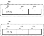
上記タスクコマンドは、図3に例示するように、当該タスクコマンドより実行されるタスク(この場合はタスクAまたはタスクB)を判別可能なタスク識別符号(インデックス等)301を有する。 As illustrated in FIG. 3, the task command has a task identification code (index or the like) 301 that can determine a task (in this case, task A or task B) executed by the task command.
また、上記タスクコマンドは、当該タスクコマンドにより実行が指定されたタスク(この場合はタスクAまたはタスクB)と実行順序において依存関係がある他のタスクを指定するタスク依存関係情報を有する。より具体的には、タスク依存関係情報は、図3に例示する前タスク依存情報302と、後タスク依存情報303とを含む。
Further, the task command has task dependency information that specifies another task that has a dependency in the execution order with the task (in this case, task A or task B) whose execution is specified by the task command. More specifically, the task dependency information includes
前タスク依存情報302は、上記コマンドにおいて指定されたタスクと、係るタスクより前に実行されるタスクとの間に依存関係が存在するか否かを表す情報である。また、後タスク依存情報は、上記コマンドにおいて指定されたタスクと、係るタスクより後に実行されるタスクとの間に依存関係が存在するか否かを表す情報である。
The previous
以下、上記タスクコマンドにおいて指定されたタスクに対して、前タスク依存情報が設定されたタスクを「前依存タスク」と称する場合がある。また、上記コマンドにおいて指定されたタスクに対して、後タスク依存情報が設定されたタスクを「後依存タスク」と称する場合がある。上記タスクコマンドには、タスク識別符号301、前タスク依存情報302、後タスク依存情報303以外に、タスクの実行に関する任意のデータが含まれてもよい。
Hereinafter, a task in which previous task dependency information is set for the task specified in the task command may be referred to as a “previous task”. A task in which post-task dependency information is set for a task specified in the above command may be referred to as a “post-dependent task”. The task command may include arbitrary data related to the execution of the task, in addition to the
以下の説明においては、図4または図5に例示するタスクコマンドA、タスクコマンドBが、演算制御部101より出力されること想定とする。 In the following description, it is assumed that the task command A and the task command B illustrated in FIG. 4 or FIG.
図4に例示する具体例においては、タスクコマンドA(401)には、タスク識別符号として「タスクA」が設定され、タスクコマンドB(402)には、タスク識別符号として「タスクB」が設定される。そして、図4に例示する具体例においては、これらのタスクコマンドA、タスクコマンドBには、タスク依存関係情報が設定されていない。これより、各演算部(104乃至106)は、タスクAに関する演算処理とタスクBに関する演算処理とを独立して実行可能である。 In the specific example illustrated in FIG. 4, “task A” is set as the task identification code in the task command A (401), and “task B” is set as the task identification code in the task command B (402). Is done. In the specific example illustrated in FIG. 4, task dependency information is not set in these task commands A and B. As a result, each of the arithmetic units (104 to 106) can independently execute the arithmetic processing for the task A and the arithmetic processing for the task B.
図5に例示する具体例においては、タスクコマンドA(501)には、タスク識別符号として「タスクA」が設定され、タスクコマンドB(502)には、タスク識別符号として「タスクB」が設定される。そして、タスクコマンドAには、後タスク依存情報303として「タスクB」が設定されており、タスクコマンドBには、前タスク依存情報302として「タスクA」が設定されている。この場合、各演算部(104乃至106)は、タスクAに関する演算処理の実行が完了した後に、タスクBに関する演算処理を実行する必要がある。
In the specific example illustrated in FIG. 5, “task A” is set as the task identification code in the task command A (501), and “task B” is set as the task identification code in the task command B (502). Is done. In the task command A, “task B” is set as the
また、上記タスク設定テーブル(112b乃至114b)には、図6に例示するように、タスクAに対する開始演算ノード番号として、「#0」が、終了演算ノード番号として「#2」が格納されていることを想定する。また、上記タスク設定テーブル(112b乃至114b)には、図6に例示するように、タスクBに対する開始演算ノード番号として、「#1」が、終了演算ノード番号として「#2」が予め格納されていることを想定する。 In the task setting tables (112b to 114b), as illustrated in FIG. 6, “# 0” is stored as the start operation node number for task A, and “# 2” is stored as the end operation node number. It is assumed that In the task setting tables (112b to 114b), as illustrated in FIG. 6, “# 1” is stored in advance as the start operation node number for task B, and “# 2” is stored as the end operation node number. Assume that
演算ノード番号「#0」、「#1」、及び、「#2」は、それぞれ、演算部104、演算部105、及び、演算部106を示す。演算ノード番号と、各演算部との関係は、予めタスク設定テーブル(112b乃至114b)や、タスク制御部(112乃至114)に設定されていてもよい。
The operation node numbers “# 0”, “# 1”, and “# 2” indicate the
また、以下においては、開始演算ノード番号に該当する開始演算部から、演算ノード番号が増大する順に、順次終了演算ノード番号に該当する終了演算部まで、タスクに関する演算処理が実行されることを前提とする。即ち、タスクAについては、演算ノード番号が「#0」、「#1」、「#2」の順に、それぞれの演算ノード番号に該当する演算部における処理が実行される。また、タスクBについては、演算ノード番号が、「#1」、「#2」の順に、それぞれの演算ノード番号に該当する演算部における処理が実行される。 Also, in the following description, it is assumed that the arithmetic processing related to the task is executed from the start arithmetic unit corresponding to the start arithmetic node number to the end arithmetic unit corresponding to the end arithmetic node number in order of increasing arithmetic node numbers. And That is, for the task A, the processing in the calculation unit corresponding to each calculation node number is executed in the order of the calculation node numbers “# 0”, “# 1”, and “# 2”. In addition, for the task B, the processing in the calculation unit corresponding to each calculation node number is executed in the order of the calculation node numbers “# 1” and “# 2”.
それぞれのタスク(タスクA及びタスクB)について、各演算部(104乃至106)において実行される処理の具体的な内容は、適宜定められてよい。 For each task (task A and task B), the specific contents of the processing executed in each of the operation units (104 to 106) may be determined as appropriate.
また、以下の説明においては、各演算部(104乃至106)における演算処理の実行状態を表すステータス情報が各演算部(104乃至106)から、それぞれタスク制御部(112乃至114)に入力される。係るステータス情報は、「待機中」、「処理実行中」、及び、「処理終了」を表す情報である。下記説明においては、「待機中」を表すステータス情報に「0」が、「処理実行中」を表すステータス情報に「1」が、「処理終了」を表すステータス情報に「2」が、それぞれ割り当てられることを想定する。なお、本実施形態はこれには限定されず、ステータス情報を表現する形式は、適宜定められてよい。また、本実施形態においては、各演算部(104乃至106)に関して、「待機中」、「処理実行中」、及び、「処理終了」以外の状態を表すステータス情報が、タスク制御部(112乃至114)に入力されてもよい。 Further, in the following description, status information indicating the execution state of the arithmetic processing in each arithmetic unit (104 to 106) is input from each arithmetic unit (104 to 106) to the task control unit (112 to 114). . Such status information is information indicating “waiting”, “processing in progress”, and “processing completed”. In the following description, “0” is assigned to the status information indicating “waiting”, “1” is assigned to the status information indicating “processing in progress”, and “2” is assigned to the status information indicating “processing completed”. It is assumed that Note that the present embodiment is not limited to this, and the format for expressing the status information may be determined as appropriate. In the present embodiment, status information indicating states other than “waiting”, “processing in progress”, and “processing completed” for each of the operation units (104 to 106) is transmitted to the task control unit (112 to 106). 114).
以下、主に各タスク制御部(112乃至114)の動作を中心に、本実施形態における演算装置100の動作について説明する。
Hereinafter, the operation of the
まず、演算制御部101が、タスクAとタスクBとの実行を指定するコマンド(タスクコマンドA、タスクコマンドB)をそれぞれ生成する。そして、演算制御部101は、タスクコマンドA、及び、タスクコマンドBを、FIFO107乃至109、並びに、タスク制御部(112乃至114)に入力する。
First, the
各FIFO107乃至109は、入力されたタスクコマンドA及びタスクコマンドBを保持する。同様に、各タスク制御部(112乃至114)は、入力されたタスクコマンドA及びタスクコマンドBを保持してもよい。
Each of the
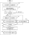
各タスク制御部(112乃至114)は、タスクコマンドAが入力された場合、下記ステップ(図7乃至図9に例示)に従って、各タスク制御部(112乃至114)が制御対象とする演算部(104乃至106)において、タスクAが実行可能であるか否かを判定する。
When the task command A is input, the task control units (112 to 114) control the operation units (112 to 114) to be controlled by the task control units (112 to 114) according to the following steps (exemplified in FIGS. 7 to 9). In
タスクコマンドAが入力された場合、各タスク制御部(112乃至114)は、それぞれが有するタスク設定テーブル(112b乃至114b)を参照し、タスクAに関して設定された情報を取得する(ステップS701)。より具体的には、各タスク制御部(112乃至114)はそれぞれ、タスク設定テーブル(112b乃至114b)から、タスクAに対する開始演算ノード番号と、終了演算ノード番号とを読み出す。この場合、図6に例示するように、タスクAに対する開始演算ノード番号201には「#0」(演算部104に対応)が、終了演算ノード番号には「#2」(演算部106に対応)が設定されている。
When the task command A is input, each task control unit (112 to 114) refers to the task setting table (112b to 114b) included in the task control unit (112 to 114b) and acquires information set for the task A (step S701). More specifically, each of the task control units (112 to 114) reads the start operation node number and the end operation node number for the task A from the task setting tables (112b to 114b). In this case, as illustrated in FIG. 6, “# 0” (corresponding to the operation unit 104) is set as the start
次に、各タスク制御部(112乃至114)は、タスク設定テーブル(112b乃至114b)の設定に基づいて、各演算部(104乃至106)が、タスクコマンドにおいて指定されたタスクの処理に含まれるか否かを確認する(ステップS702)。より具体的には、各タスク制御部(112乃至114)は、例えば、それぞれの制御対象である各演算部(104乃至106)が、タスクAに関する演算処理を実行する演算部として指定されているか否かを確認する。 Next, in each of the task control units (112 to 114), based on the settings in the task setting tables (112b to 114b), each operation unit (104 to 106) is included in the processing of the task specified in the task command. It is determined whether or not this is the case (step S702). More specifically, each of the task control units (112 to 114) determines, for example, whether each of the operation units (104 to 106) to be controlled is specified as an operation unit that executes the operation process regarding the task A. Check whether or not.
上記ステップS702における確認の結果、制御対象である演算部がタスク(例えばタスクA)に関する演算処理を実行しない場合(ステップS703においてNO)、各タスク制御部(112乃至114)は、ステップS701に戻って処理を実行する。この場合、例えば、次のタスク(この場合はタスクB)についてステップS701から処理を実行してもよい。また、全てのタスクについて処理を実行した場合は、演算制御部101からの次のタスクコマンドの入力を待ってもよい。
As a result of the confirmation in step S702, when the arithmetic unit to be controlled does not execute the arithmetic processing on the task (for example, task A) (NO in step S703), each task control unit (112 to 114) returns to step S701. To execute the process. In this case, for example, the process may be executed from step S701 for the next task (task B in this case). When the process has been performed for all tasks, the process may wait for the input of the next task command from the
タスクAについては、各演算部(104乃至106)が、タスクA処理に関する演算処理を実行する演算部として指定されている。よって、各タスク制御部(112乃至114)によるステップS703における確認結果は、「YES」(「含まれる」)となる。 For the task A, each of the calculation units (104 to 106) is specified as a calculation unit that executes a calculation process related to the task A process. Therefore, the confirmation result in step S703 by each task control unit (112 to 114) is “YES” (“included”).
上記ステップS703における確認結果がYESの場合、各タスク制御部(112乃至114)は、演算部(104乃至106)のステータス情報を取得する(ステップS704)。この場合、タスクコマンドAが入力された時点では、各演算部(104乃至106)は演算処理を実行していないので、各演算部(104乃至106)のステータス情報は「待機中(0)」を表す。 If the confirmation result in the above step S703 is YES, each task control unit (112 to 114) acquires status information of the calculation unit (104 to 106) (step S704). In this case, when the task command A is input, the operation units (104 to 106) are not executing the operation processing, and therefore the status information of each operation unit (104 to 106) is "waiting (0)". Represents
次に、各タスク制御部(112乃至114)は、ステップS704において取得したステータス情報を用いて、各演算部(104乃至106)がタスクを実行可能であるか否かを判定する(ステップS705)。より具体的には、各タスク制御部(112乃至114)は、それぞれの制御対象である各演算部(104乃至106)が、タスクAに関する演算処理を実行可能であるか否かを判定する。 Next, each task control unit (112 to 114) determines whether each operation unit (104 to 106) can execute the task using the status information acquired in step S704 (step S705). . More specifically, each of the task control units (112 to 114) determines whether or not each of the operation units (104 to 106) to be controlled is capable of executing the operation process regarding the task A.
以下、図8に例示するフローチャートを参照してステップS705における処理について説明する。まず、各タスク制御部(112乃至114)は、それぞれの制御対象である演算部(104乃至106)に関するステータス情報が、「処理実行中(1)」であるか否かを確認する(ステップS801)。この場合、上記ステップS704の結果から、各演算部(104乃至106)に関するステータス情報は「待機中(0)」を表し、ステップS802における確認結果は「NO」となる。ステップS801における確認の結果、ステップS802において「YES」と判定された場合、当該制御対象である演算部は、何らかのタスクに関する演算処理を実行中である。よって、各タスク制御部(112乃至114)は、それぞれの制御対象である演算部(104乃至106)に対するタスクの投入(入力)は不可であると判定する(ステップS809)。 Hereinafter, the processing in step S705 will be described with reference to the flowchart illustrated in FIG. First, each task control unit (112 to 114) confirms whether or not the status information relating to the respective calculation units (104 to 106) to be controlled is "processing in progress (1)" (step S801). ). In this case, from the result of step S704, the status information on each of the calculation units (104 to 106) indicates "waiting (0)", and the confirmation result in step S802 is "NO". As a result of the check in step S801, if “YES” is determined in step S802, the arithmetic unit to be controlled is performing arithmetic processing related to some task. Therefore, each task control unit (112 to 114) determines that it is impossible to input (input) a task to the operation unit (104 to 106) to be controlled (step S809).
ステップS802においてNOの場合、タスク制御部(112乃至114)は、それぞれの制御対象である演算部(104乃至106)が、タスクコマンドにより指定されたタスクの開始演算部に該当するか否かを確認する(ステップS803)。この場合、タスク制御部(112乃至114)は、それぞれの制御対象である演算部(104乃至106)がタスクAの開始演算部に該当するか否かを判定する。 In the case of NO in step S802, the task control units (112 to 114) determine whether the control units (104 to 106) to be controlled correspond to the start calculation units of the task specified by the task command. Confirm (step S803). In this case, the task control units (112 to 114) determine whether the operation units (104 to 106) to be controlled correspond to the start operation unit of the task A.
タスク設定テーブル(112b乃至114b)には、タスクAの開始演算ノード番号が「#0」と設定されている。これより、開始演算部は演算部104である。よって、ステップS802における確認の結果、タスク制御部112は制御対象である演算部104が、タスクAの開始演算部に該当すると判定する(ステップS804においてYES)。
In the task setting tables (112b to 114b), the start operation node number of task A is set to “# 0”. Thus, the start calculation unit is the
また、この場合、他のタスク制御部113、及び、タスク制御部114は、ステップS803における確認の結果、制御対象である演算部(演算部105、演算部106)が、タスクAの開始演算部に該当しないと判定する(ステップS804においてNO)。
In this case, the other
この場合、タスク制御部113及び114は、各演算部(演算部105及び106)の前段の演算部において、タスクAに関する処理が完了しているか否かを確認する(ステップS806)。
In this case, the
より具体的には、タスク制御部113は、例えば、タスク設定テーブル113bを参照することにより、制御対象である演算部105の前段となる演算部(演算部104)を特定する。タスク制御部113は、演算部105の演算ノード番号(「#1」)を参照し、係る演算ノード番号より一つ前の演算ノード番号(「#0」)に対応する演算部104を特定してもよい。
More specifically, the
そして、タスク制御部113は、当該演算部104のステータス情報を参照することにより、タスクAに関する演算処理が終了しているか否かを確認する。この場合、演算部104におけるタスクAに関する演算処理は終了していないので、タスク制御部113は、ステップS807においてNOと判定する。
Then, the
同様に、タスク制御部114は、演算部106に対する前段の演算部(演算部105)において、タスクAに関する演算処理が終了していないので、ステップS807においてNOと判定する。
Similarly, the
これにより、タスク制御部113、及び、タスク制御部114は、制御対象である演算部(演算部105及び106)に対するタスクAの投入は不可であると判定する(ステップS809)。
Accordingly, the
図7に戻って、上記ステップS809の結果、タスク制御部113、及び、タスク制御部114は、演算部105及び106におけるタスクAの処理を抑制する(ステップS710)。
Returning to FIG. 7, as a result of the above step S809, the
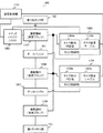
再び図8に戻って、次に、タスク制御部112は、タスクコマンドより指定されたタスク(この場合はタスクA)に関して、依存関係にあるタスクを確認する(ステップS805)。以下、図9を参照して、ステップS805における処理について説明する。
Returning to FIG. 8 again, next, the
まず、タスク制御部112は、演算制御部101から入力されたタスクコマンド(この場合タスクコマンドA)に設定されたタスク依存関係情報(図3における302、303)を参照する。そして、タスク制御部112は、タスクAと依存関係があるタスクが存在するか否かを確認する(ステップS901)。
First, the
この場合、タスクコマンドAには前タスク依存情報が設定されていないことから、タスク制御部112は依存関係にある前依存タスクが無いと判定する(ステップS902においてNO)。
In this case, since the previous task dependency information is not set in the task command A, the
そして、タスク制御部112は、制御対象である演算部104に対してタスク(この場合はタスクA)を投入可能であると判定する(ステップS903)。即ち、タスク制御部112は、制御対象である演算部104においてタスクAを実行可能であると判定する。ステップS902においてYESの場合の動作については、後述する。
Then, the
再び図7に戻り、ステップS903の判定結果から、タスク制御部112は、ステップS705において、制御対象である演算部104に対してタスクAを投入可能であると判定する(ステップS706においてYES)。
Returning to FIG. 7 again, based on the determination result in step S903, the
次に、タスク制御部112は、演算部104に対してタスク実行制御信号(タスクコマンド)及び、タスク実行に必要なデータを出力する(ステップS708)。より具体的には、タスク制御部112は、FIFO107を制御して、FIFO107が保持するタスクコマンドAを演算部104に出力する。タスク制御部112は、必要に応じて、第1のメモリ部102から、タスクAの実行に必要なデータを読み込むよう、演算部104を制御してもよい。
Next, the
ステップS708における処理の結果、演算部104において、タスクAに関する演算処理が実行される。演算部104における、タスクAに関する演算処理の結果は、データバッファ110に一旦格納される。データバッファ110がほぼ演算部104の演算結果で満たされた場合(空き容量が少なくなった場合)は、データバッファ110が、特定の信号(「AlmostFull」信号)を演算部104に出力する。この場合、演算部104における演算処理はストールする。データバッファ110が「AlmostFull」信号を出力する空き容量のサイズは、適宜設定可能としてよい。
As a result of the processing in step S708, the
タスク制御部112は、ステップS708の後、次のタスクの制御へ遷移する(ステップS709)。より具体的には、タスク制御部112は、例えば、演算部104のステータス情報を確認し、この場合はタスクAに関する演算処理の終了を待機する。そして、タスク設定テーブル112bと、入力されたタスクコマンドとを参照し、ステップS701から次のタスク(この場合はタスクB)に関する制御を開始する。
After step S708, the
演算部104において、タスクAに関する処理が終了すると、演算部104のステータス情報が「処理終了(2)」となる。
When the processing regarding the task A is completed in the
上記ステップS710において制御対象である演算部105に対するタスクAの投入を抑制したタスク制御部113は、再びステップS704において、演算部104のステータス情報を取得する。この場合、係るステータス情報は「処理終了(2)」である。
The
次に、タスク制御部113は、ステップS705(ステップS801乃至S806)の処理を実行する。その結果、タスク制御部113は、前段の演算部104においてタスクAに関する演算処理が終了していることから、演算部105にタスクAを投入可能であると判定する(ステップS808)。即ち、この場合、ステップS706における判定結果がYESとなる。
Next, the
この際、タスク制御部114は、再びステップS704乃至S706を実行する。この場合、演算部106に対する前段の演算部105において、タスクAに関する演算処理が終了していない。よってタスク制御部114は、演算部106に対するタスクAの投入は不可であると判定する。
At this time, the
次に、タスク制御部113は、制御対象である演算部105に対してタスク実行制御信号(タスクコマンド)及び、タスク実行に必要なデータを出力する(ステップS708)。より具体的には、タスク制御部113は、FIFO108を制御して、FIFO108が保持するタスクコマンドAを演算部105に出力する。また、タスク制御部113は、データバッファ110を制御して、演算部104の出力(演算結果)を、演算部105に出力する。タスク制御部113は、必要に応じて、第1のメモリ部102から、タスクAの実行に必要なデータを読み込むよう、演算部105を制御してもよい。
Next, the
ステップS708における処理の結果、演算部105において、タスクAに関する演算処理が実行される。演算部105におけるタスクAに関する演算処理の結果は、データバッファ111に一旦格納される。データバッファ111がほぼ演算部105の演算結果で満たされた場合(空き容量が少なくなった場合)は、データバッファ111が「AlmostFull」の信号を演算部105に出力する。この場合、演算部105における演算処理はストールする。データバッファ111が「AlmostFull」信号を出力する空き容量のサイズは、適宜設定可能である。
As a result of the processing in step S708, the
タスク制御部113は、ステップS708の後、次のタスクの制御へ遷移する(ステップS709)。より具体的には、タスク制御部113は、例えば、演算部105のステータス情報を確認し、この場合はタスクAに関する演算処理の終了を待機する。そして、タスク設定テーブル113bと、入力されたタスクコマンドとを参照し、ステップS701から次のタスク(この場合はタスクB)に関する制御を開始する。
After step S708, the
演算部104におけるタスクAに関する演算処理が終了した際、タスク制御部112は、ステップS701から処理を開始する。この場合、タスク制御部112は、タスク設定テーブル112bを参照する(ステップS701)。タスク制御部112は、タスク設定テーブル112bの内容と、演算制御部101から出力されたタスクコマンドとに基づいて、次のタスクは「タスクB」であると確認する。
When the arithmetic processing on the task A in the
次に、タスク制御部112は、制御対象である演算部104が、タスクBの処理に含まれるか確認する(ステップS702)。タスク設定テーブル112bを参照すると、タスクBの開始演算ノード番号は「#1」である。演算ノード番号「#1」は、演算部105を示す。このため、タスク制御部112は、制御対象である演算部104が「タスクB」の処理に含まれないと判定する(ステップS703においてNO)。この場合、タスク制御部112と、演算部104とは、演算制御部101から次のタスクが出力されるまで、待機状態となる。
Next, the
演算部105においてタスクAに関する処理が終了すると、演算部105のステータス情報が「処理終了(2)」を表すように更新される。
When the processing regarding the task A is completed in the
上記ステップS710において制御対象である演算部106に対するタスクAの投入を抑制したタスク制御部114は、再びステップS704において、演算部105のステータス情報を取得する。この場合、係るステータス情報は「処理終了(2)」を表す。
The
次に、タスク制御部114は、ステップS705(ステップS801乃至S807)の処理を実行する。その結果、タスク制御部114は、前段の演算部105においてタスクAに関する演算処理が終了していることから、演算部106にタスクAを投入可能であると判定する(ステップS808)。
Next, the
次に、タスク制御部114は、制御対象である演算部106に対してタスク実行制御信号(タスクコマンド)及び、タスク実行に必要なデータを出力する(ステップS708)。より具体的には、タスク制御部114は、FIFO109を制御して、FIFO109が保持するタスクコマンドAを演算部106に出力する。また、タスク制御部114は、データバッファ111を制御して、演算部105の出力(演算結果)を、演算部106に出力する。タスク制御部114は、必要に応じて、第1のメモリ部102から、タスクAの実行に必要なデータを読み込むよう、演算部106を制御してもよい。
Next, the
ステップS708における処理の結果、演算部106において、タスクAに関する演算処理が実行される。演算部106におけるタスクAに関する演算処理の結果は、第2のメモリ部103に出力されてもよい。
As a result of the processing in step S708, the
タスク制御部114は、ステップS708の後、次のタスクの制御へ遷移する(ステップS709)。より具体的には、タスク制御部114は、例えば、演算部106のステータス情報を確認し、この場合はタスクAに関する演算処理の終了を待機する。そして、タスク設定テーブル114bと、入力されたタスクコマンドとを参照し、ステップS701から次のタスク(この場合はタスクB)に関する制御を開始する。
After step S708, the
演算部105におけるタスクAに関する演算処理が終了した際、タスク制御部113は、ステップS701から処理を開始する。この場合、タスク制御部113は、タスク設定テーブル113bを参照する(ステップS701)。タスク制御部113は、タスク設定テーブル113bの内容と、演算制御部101から出力されたタスクコマンドとに基づいて、次のタスクは「タスクB」であると確認する。
When the arithmetic processing regarding the task A in the
次に、タスク制御部113は、制御対象である演算部105が、タスクBの処理に含まれるか否かを確認する(ステップS702)。タスク設定テーブル113bを参照すると、タスクBの開始演算ノード番号は「#1」である。演算ノード番号「#1」は、演算部105を示す。このため、タスク制御部113は、制御対象である演算部105が「タスクB」の処理に含まれると判定する(ステップS703においてYES)。
Next, the
次に、タスク制御部113は、ステップS704及びS705を実行する。この際、タスク制御部113は、ステップS803において、制御対象である演算部105が、タスクBの開始演算部であることを確認する(ステップS804においてYES)。
Next, the
次に、タスク制御部113は、ステップS805を実行する。この際、タスク制御部113は、タスクコマンドBのタスク依存関係情報(図3における302、303)を参照し、依存関係があるタスクが存在するか否か確認する(ステップS901)。
Next, the
まず、図4に示すタスクコマンドA(401)、タスクコマンドB(402)のように、タスク依存関係情報が設定されていない場合について説明する。この場合、タスクBとタスクAは独立して実行可能である。この場合、タスク制御部113は依存関係にあるタスクが無いと判定する(ステップS902においてNO)。
First, a case where task dependency information is not set, such as the task command A (401) and the task command B (402) shown in FIG. 4, will be described. In this case, task B and task A can be executed independently. In this case, the
そして、タスク制御部113は、制御対象である演算部105に対してタスク(この場合はタスクB)を投入可能(即ち、演算部105がタスクBを実行可能)であると判定する(ステップS903)。
Then, the
この場合、タスク制御部113は、制御対象である演算部105に対してタスク実行制御信号(タスクコマンド)及び、タスク実行に必要なデータを出力する(ステップS708)。より具体的には、タスク制御部113は、FIFO108を制御して、FIFO108が保持するタスクコマンドBを演算部105に出力する。タスク制御部113は、必要に応じて、第1のメモリ部102から、タスクBの実行に必要なデータを読み込むよう、演算部105を制御してもよい。
In this case, the
ステップS708における処理の結果、演算部105において、タスクBに関する演算処理が実行される。以降の処理は、上記説明した演算部105におけるタスクAに関する演算処理と同様である。
As a result of the process in step S708, the
次に、仮に、図5に示すタスクコマンドA(501)、タスクコマンドB(502)のように、タスク依存関係情報が設定された場合について説明する。この場合、タスクBとタスクAとの間に依存関係が存在することから、タスクBは、タスクAの終了後に実行される必要がある。この場合、タスク制御部113がステップS901を実行した結果、ステップS902における確認結果がYESとなる。
Next, a case where task dependency information is set, such as a task command A (501) and a task command B (502) shown in FIG. 5, will be described. In this case, since there is a dependency between task B and task A, task B needs to be executed after completion of task A. In this case, as a result of executing step S901 by the
タスク制御部113は、タスク設定テーブル113bを参照し、タスクBと依存関係があるタスク(タスクA)の終了演算部を特定する(ステップS904)。タスクAの終了演算部は、演算部106(終了演算ノード番号が「#2」)である。
The
次に、タスク制御部113は、ステップS904において特定した演算部(演算部106)のステータス情報を確認する。そして、当該演算部106のステータス情報に基づいて、演算部106において、タスクBと依存関係のあるタスク(タスクA)に関する演算処理が終了しているか確認する(ステップS905)。
Next, the
この段階では、上記の通り、演算部105においてタスクAに関する演算処理が終了しているものの、演算部106におけるタスクAに関する処理は終了していない場合がある。演算部106におけるタスクAに関する処理は終了していない場合、ステップS906における確認結果はNOとなる。この場合、タスク制御部113は、演算部105に対するタスクBの投入は不可であると判定する(ステップS907)。この場合、タスク制御部113は、タスクBの実行を抑制する(ステップS710)。より具体的には、タスク制御部113は、例えば、FIFO108からのタスクコマンドBの出力等を抑制してもよい。
At this stage, as described above, the
次に、演算部106においてタスクAに関する処理が終了すると、演算部106のステータス情報が「処理終了(2)」となる。
Next, when the processing regarding the task A is completed in the
再び、図5に示すタスクコマンドA(501)、タスクコマンドB(502)のように、タスク依存関係情報が設定された場合について説明する。 Again, a case where the task dependency information is set like the task command A (501) and the task command B (502) shown in FIG. 5 will be described.
上記ステップS710において、制御対象である演算部106に対するタスクBの投入を抑制したタスク制御部113は、ステップS704において、演算部106のステータス情報を取得する。この場合、係るステータス情報は「処理終了(2)」である。
The
次に、タスク制御部113は、ステップS705(ステップS801乃至S805)の処理を実行する。その結果、タスク制御部113は、タスクBと依存関係のあるタスクAに関する演算処理が終了している(ステップS901乃至ステップS905)と判定する。これより、タスク制御部113は、演算部105にタスクBを投入可能であると判定する(ステップS906においてYES)。即ち、この場合、ステップS706における判定結果がYESとなる。
Next, the
次に、タスク制御部113は、制御対象である演算部105に対してタスク実行制御信号(タスクコマンド)及び、タスク実行に必要なデータを出力する(ステップS708)。より具体的には、タスク制御部113は、FIFO108を制御して、FIFO108が保持するタスクコマンドBを演算部105に出力する。また、タスク制御部113は、データバッファ110を制御して、データバッファ110の内容を、演算部105に出力してもよい。タスク制御部113は、必要に応じて、第1のメモリ部102から、タスクBの実行に必要なデータを読み込むよう、演算部105を制御してもよい。
Next, the
ステップS708における処理の結果、演算部105において、タスクBに関する演算処理が実行される。演算部105におけるタスクBに関する演算処理の結果は、データバッファ111に一旦格納される。以下の処理は、上記説明した演算部105におけるタスクAの処理と同様である。
As a result of the process in step S708, the
演算部106におけるタスクAに関する演算処理が終了した際、タスク制御部114は、ステップS701から処理を開始する。この場合、タスク制御部114は、タスク設定テーブル114bを参照する(ステップS701)。タスク制御部114は、タスク設定テーブル114bの内容と、演算制御部101から出力されたタスクコマンドに基づいて、次のタスクは「タスクB」であると確認する。
When the calculation process for the task A in the
次に、タスク制御部114は、制御対象である演算部106が、タスクBの処理に含まれるか確認する(ステップS702)。タスク設定テーブル112bを参照すると、タスクBの終了演算ノード番号は「#2」である。このため、タスク制御部114は、制御対象である演算部106が「タスクB」の処理に含まれると判定する(ステップS703においてYES)。
Next, the
次に、タスク制御部114は、ステップS704及びS705を実行する。この際、タスク制御部114は、ステップS803において、制御対象である演算部106がタスクBの開始演算部では無いことを確認する(ステップS804においてNO)。
Next, the
この場合、タスク制御部114及は、演算部106の前段の演算部105において、タスクBに関する処理が完了しているか確認する(ステップS806)。この場合、演算部105におけるタスクBに関する演算処理は終了していないので、タスク制御部114は、ステップS807においてNOと判定する。これにより、タスク制御部114は、制御対象である演算部106に対するタスクBの投入は不可であると判定する(ステップS809)。
In this case, the
図7に戻って上記ステップS809の結果、演算部106におけるタスクBの処理は抑制される(ステップS710)。
Returning to FIG. 7, as a result of step S809, the processing of task B in
次に、演算部105においてタスクBに関する処理が終了すると、演算部105のステータス情報が「処理終了(2)」となる。
Next, when the processing regarding the task B is completed in the
上記ステップS710において制御対象である演算部106に対するタスクBの投入を抑制したタスク制御部114は、再びステップS704において、演算部105のステータス情報を取得する。この場合、係るステータス情報は「処理終了(2)」である。
The
次に、タスク制御部114は、ステップS705(ステップS801乃至S807)の処理を実行する。その結果、タスク制御部114は、前段の演算部105においてタスクBに関する演算処理が終了していることから、演算部106にタスクBを投入可能であると判定する(ステップS808)。
Next, the
次に、タスク制御部114は、制御対象である演算部106に対してタスク実行制御信号(タスクコマンド)及び、タスク実行に必要なデータを出力する(ステップS708)。より具体的には、タスク制御部114は、FIFO109を制御して、FIFO109が保持するタスクコマンドBを演算部106に出力する。また、タスク制御部114は、データバッファ111を制御して、演算部105の出力(演算結果)を、演算部106に出力する。タスク制御部114は、必要に応じて、第1のメモリ部102から、タスクBの実行に必要なデータを読み込むよう、演算部106を制御してもよい。
Next, the
ステップS708における処理の結果、演算部106において、タスクBに関する演算処理が実行される。演算部106におけるタスクBに関する演算処理の結果は、第2のメモリ部103に出力されてもよい。
As a result of the process in step S708, the
演算部106において、タスクBの処理が終了すると、演算部106のステータス「処理終了(2)」となり、演算制御部101から投入されたタスクA、タスクBに関する演算処理が終了する。
When the processing of the task B is completed in the
以上説明したように、本実施形態によれば、演算装置100において、各演算部(104乃至106)が効率的に稼働するようにタスクの実行が制御される。ここで、係る演算装置100は、複数の演算部(104乃至106)が、データバッファ(110乃至111)を介してパイプライン状に接続された構成を有する。即ち、本実施形態における演算装置100は、複数の演算部(104乃至106)を用いてパイプライン的に演算処理を実行するタスクを実行する際、各演算部におけるアイドル状態やレイテンシを削減することが可能である。これにより、本実施形態における演算装置100は、パイプラインのオーバーヘッドを低減可能である。
As described above, according to the present embodiment, in the
より具体的には、本実施形態における演算装置100は、特定のタスクに関する全ての演算処理の終了を待たずに、一部の演算部において、当該特定のタスクと依存関係の無い他のタスクに関する演算処理を実行可能である。
More specifically, the
上記説明した具体例においては、演算装置100は、例えば、タスクAとタスクBとの間に依存関係が存在しない場合、タスクAの処理が終了する前に、一部の演算部においてタスクBに関する演算処理を実行可能である。より具体的には、演算装置100は、演算部106におけるタスクAに関する演算処理が終了する前に、一部の演算部(例えば、演算部105)において、タスクBに関する演算処理を実行可能である。この場合、演算装置100は、図18に例示するように、タスクAに関する演算処理が完了する前に、タスクBに関する演算処理を開始可能である。これより、本実施形態における演算装置100は、全体の処理時間を短縮可能であり、また、各演算部がアイドル状態となる期間を短くすることができる。
In the specific example described above, for example, when there is no dependency between the task A and the task B, the
また、本実施形態における各タスク制御部(112乃至114)は、各演算部(104乃至106)においてタスクに関する演算処理が実行されるか否かを制御する。即ち、各タスク制御部が詳細なタスク制御を実行されることから、上位の制御系(例えば、演算制御部101等)におけるタスク制御に関する負荷が増大しない。
Each task control section in the present embodiment (112 to 114) controls whether arithmetic processing related tasks are performed in each computation unit (104 to 106). That is, since each task control section is performed a detailed task control, higher-level control system (e.g., arithmetic and
以上より、本実施形態における演算装置100は、タスクに関する演算処理の効率を向上し、演算処理を高速化可能である。その理由は、各演算部(104乃至106)の実行状態(ステータス)と、各タスクの設定情報(各タスク設定テーブル(112b乃至114b)、及びタスクコマンド等)とに基づいて、演算部毎に、タスクの実行が制御されるからである。
As described above, the
<第2の実施形態>
次に、本願発明の第2の実施形態について説明する。以下の説明においては、本実施形態に係る特徴的な構成を中心に説明する。上述した第1の実施形態と同様な構成に関する重複する説明は省略される。<Second embodiment>
Next, a second embodiment of the present invention will be described. In the following description, the characteristic configuration according to the present embodiment will be mainly described. A duplicate description of the same configuration as that of the first embodiment described above is omitted.
本実施形態は、上記第1の実施形態と、各タスク設定テーブル(112b乃至114b)に設定される情報の種類のみ異なり、その他は同様である。このため、本実施形態における演算装置100の構成は、上記第1の実施形態における演算装置100と同様としてよい。
This embodiment differs from the first embodiment only in the type of information set in each task setting table (112b to 114b), and is otherwise the same. For this reason, the configuration of the
上記第1の実施形態においては、図2に例示するように、タスク設定テーブル(112b乃至114b)には、実行されるタスク毎に、各タスクに対する開始演算ノード番号201と、終了演算ノード番号202とが設定される。
In the first embodiment, as illustrated in FIG. 2, the task setting tables (112b to 114b) include, for each task to be executed, a start
これに対して、本実施形態におけるタスク設定テーブル(112b乃至114b)には、図10に例示するように、実行されるタスク毎に、各タスクに対する開始演算ノード番号201と、各タスクが使用する演算部の個数を表す使用演算ノード数1002とが設定される。
On the other hand, in the task setting tables (112b to 114b) according to the present embodiment, as illustrated in FIG. 10, for each task to be executed, a start
各タスク制御部は、特定のタスクに関して、上記開始演算ノード番号201と、使用演算ノード数1002とに基づいて、当該タスクの終了演算部を特定する。この場合、各タスク制御部は、上記開始演算ノード番号201と、使用演算ノード数1002とに基づいて、上記第1の実施形態における終了演算ノード番号を算出してもよい。
Each task control unit specifies, for a specific task, an end operation unit of the task based on the start
本実施形態における各タスク制御部は、上記説明したステップS904において、上記開始演算ノード番号201と、使用演算ノード数1002とに基づいて、当該タスクの終了演算部を特定する。その他の動作については、上記第1の実施形態と同様である。
In step S904 described above, each task control unit in the present embodiment specifies the end operation unit of the task based on the start
以上より、本実施形態における演算装置100は、上記第1の実施形態における演算装置100と同様の効果を奏する。また、本実施形態における演算装置100は、終了演算部を直接指定する必要が無く、使用する演算部の個数のみを指定することにより、各演算部においてタスクに関する演算処理の実行を制御可能である。
As described above, the
<第3の実施形態>
次に、本願発明の第3の実施形態について説明する。以下の説明においては、本実施形態に係る特徴的な部分を中心に説明する。上述した各実施形態と同様な構成についての重複する説明は省略される。<Third embodiment>
Next, a third embodiment of the present invention will be described. In the following description, a characteristic portion according to the present embodiment will be mainly described. Duplicate descriptions of configurations similar to those of the above-described embodiments will be omitted.
以下、本実施形態について、図11を参照して説明する。 Hereinafter, the present embodiment will be described with reference to FIG.
本実施形態は、上記説明した第1の実施形態の変形例である。上記第1の実施形態における演算装置100と、本実施形態における演算装置1100との差分は、データバッファ(図11における1104、1105)と、タスク制御部(図11における1101、1102、及び、1103)とが接続されない点である。
This embodiment is a modification of the above-described first embodiment. The difference between the
上記第1の実施形態においては、タスク制御部(例えば、タスク制御部113)が、データバッファ(例えばデータバッファ110)を制御することにより、各演算部(例えば演算部105)におけるタスクの実行に必要なデータがデータバッファから出力される。または、タスク制御部(例えば、タスク制御部113)が、各演算部におけるタスクの実行に必要なデータが格納されたデータバッファの領域(アドレス等)を各演算部に通知することにより、各演算部が、係る領域からデータを取得する。 In the first embodiment, the task control unit (for example, the task control unit 113) controls the data buffer (for example, the data buffer 110) to execute the task in each arithmetic unit (for example, the arithmetic unit 105). The required data is output from the data buffer. Alternatively, the task control unit (for example, the task control unit 113) notifies each operation unit of an area (address or the like) of a data buffer in which data necessary for executing a task in each operation unit is stored, so that each operation is performed. The unit acquires data from the area.
これに対して、本実施形態における演算装置1100は、タスク制御部(1101乃至1103)は、データバッファ(1104、1105)を直接的に制御しない点において、上記第1の実施形態における演算装置100と異なる。
On the other hand, the
本実施形態においては、各データバッファ(1104、1105)に接続された前段の演算部(104、105)から、特殊なコマンドがデータバッファに出力される。 In the present embodiment, a special command is output to the data buffer from the preceding operation unit (104, 105) connected to each data buffer (1104, 1105).
具体的には、データバッファ1104の前段の演算部104は、あるタスクに関する処理を終了した際に、特殊コマンド「Sync」をデータバッファ1104に出力(投入)する。同様に、データバッファ1105の前段の演算部105は、あるタスクに関する処理を終了した際に、特殊コマンド「Sync」をデータバッファ1105に出力(投入)する。
Specifically, the
各データバッファ(1104、1105)は、特殊コマンド(「Sync」)の投入より前に投入されたデータが全て読み出されるまで、特殊コマンドが投入された後に投入されたデータの読み出しを禁止する。より具体的には、本実施形態においては、図12に例示するように、演算部105は、前段のデータバッファ1104から、特殊コマンド(「Sync」)が投入されるより前に投入されたデータを取得可能である。図12には例示していないが、演算部106についても同様である。
Each data buffer (1104, 1105) prohibits reading of the data input after the special command is input until all the data input before the input of the special command ("Sync") is read. More specifically, in the present embodiment, as illustrated in FIG. 12, the
上記のように構成された本実施形態における演算装置1100は、上記説明した第1の実施形態と同様の演算処理を実行可能である。その理由は、各データバッファ(1104,1105)が、特殊コマンドが投入された後に投入されたデータへのアクセスを禁止することにより、タスク間におけるデータへのアクセスを排他制御することが可能であるからである。
The
なお、上記説明した特殊コマンドは「Sync」に限定されない。本実施形態における演算装置1100は、「Sync」以外の任意の識別符号をコマンドとして採用してよい。
Note that the special command described above is not limited to “Sync”.
<第4の実施形態>
次に、本願発明の第4の実施形態について説明する。以下の説明においては、本実施形態に係る特徴的な部分を中心に説明する。上述した各実施形態と同様な構成についての重複する説明は省略される。<Fourth embodiment>
Next, a fourth embodiment of the present invention will be described. In the following description, a characteristic portion according to the present embodiment will be mainly described. Duplicate descriptions of configurations similar to those of the above-described embodiments will be omitted.
以下、図13を参照して、本実施形態における演算装置1300について説明する。
Hereinafter, the
演算制御部1301は、コマンドバッファ1302と接続されている。以下においてコマンドバッファ1302を、「FIFO1302」と称する場合がある。FIFO1302は、演算部1307と接続されている。他の演算部(1308、1309)に対しては、演算制御部1301から制御信号(タスクコマンド)が直接的には入力されない。
The
演算部(演算部1307、演算部1308、及び、演算部1309)は、あるタスクに関する演算処理を終了する際、当該タスクに関するタスクコマンドを、後段の演算部に受け渡す(転送する)。即ち、本実施形態においては、後段の演算部に対して、前段の演算部から、タスクコマンドがデータバッファを介して転送される。
When the arithmetic unit (the
より具体的には、演算部1308に対しては、前段の演算部1307から、データバッファ1305を介して、タスクコマンドが受け渡される(転送される)。また、演算部1309に対しては、前段の演算部1308から、データバッファ1306を介して、タスクコマンドが受け渡される。本実施形態における演算部(1307乃至1309)のその他の構成は、上記各実施形態と同様としてよい。
More specifically, a task command is transferred (transferred) from the preceding
本実施形態におけるタスク制御部1303は、制御対象である演算部1307におけるステータスを確認して、後段の演算部1308に対してタスクを投入可能か否か判断する。同様に、本実施形態におけるタスク制御部1304は、制御対象である演算部1308におけるステータスを確認して、後段の演算部1309に対してタスクを投入可能か否か判断する。
The
本実施形態においては、開始演算部が演算部1307に固定される。このため、各タスク制御部(1303、1304)が有するタスク設定テーブル(1303b、1304b)には、終了演算ノード番号、あるいは、使用演算ノード数のみが格納されてもよい。
In the present embodiment, the start calculation unit is fixed to the
本実施形態におけるデータバッファ(1305、1306)は、上記各実施形態におけるデータバッファと同様としてもよい。 The data buffers (1305, 1306) in the present embodiment may be the same as the data buffers in the above embodiments.
以下、上記のように構成された本実施形態における演算装置1300の動作について説明する。
Hereinafter, the operation of the
まず、第1のメモリ部102には、演算部(1307乃至1309)における演算処理の対象となるデータが格納されていることを想定する。
First, it is assumed that data to be subjected to arithmetic processing in the arithmetic units (1307 to 1309) is stored in the
説明の便宜上、実行されるタスクは2つ(タスクA、タスクB)とする。係る2つのタスクの内、第1のタスク(タスクA)は、演算部1307、演算部1308、及び、演算部1309において実行される。第2のタスク(タスクB)は、演算部1307、演算部1308、及び、演算部1309において実行される。
For convenience of explanation, it is assumed that two tasks are executed (task A and task B). Of these two tasks, the first task (task A) is executed by the
タスクA、及び、タスクBは、任意の演算処理を実行してよい。タスクAに関するコマンドをタスクコマンドA、タスクBに関するコマンドをタスクコマンドBとする。タスクコマンドA、タスクコマンドBは、上記第1の実施形態と同様、タスク識別符号301と、前タスク依存情報302と、後タスク依存情報303とを含む。
Task A and task B may execute any arithmetic processing. The command relating to task A is referred to as task command A, and the command relating to task B is referred to as task command B. The task command A and the task command B include a
各タスク制御部(1303、1304)におけるタスク設定テーブル(1303b、1304b)には、タスクA、及び、タスクBに対する終了演算ノード番号(図2に例示する符号202)として「#2」が格納されている。終了演算ノード番号の「#2」は、演算部1309を表す。
“# 2” is stored in the task setting tables (1303b, 1304b) of the respective task control units (1303, 1304) as end operation node numbers (
上記各実施形態と同様、各演算部(1307乃至1309)のステータスとして、待機中(「0」)、処理実行中(「1」)、処理終了(「2」)のいずれかが、各タスク制御部(1303、1304)に入力される。
Similar to the above embodiments, as the status of each calculation unit (1307 to 1309), waiting ( "0"), during the process execution ( "1"), one of ends ( "2") is, the task click system is input to the control unit (1303, 1304).
以下、各演算部(1307乃至1309)におけるタスクA、及び、タスクBの具体的な処理について、図14及び図15に例示するフローチャートを参照して説明する。 Hereinafter, specific processing of the task A and the task B in each of the operation units (1307 to 1309) will be described with reference to flowcharts illustrated in FIGS. 14 and 15.
図14に例示するフローチャートには、図7に例示するフローチャートに対して、本実施形態におけるタスク制御部(1303、1304)に特有の処理が追加されている。上記第1の実施形態における演算装置100と同様の処理については、上記第1の実施形態において説明したフローチャート(図7乃至図9)を適宜参照して説明する。
The flowchart illustrated in FIG. 14 is different from the flowchart illustrated in FIG. 7 in that processing specific to the task control units (1303 and 1304) according to the present embodiment is added. Processing similar to that of the
まず、演算制御部1301が、タスクA、及び、タスクBの実行を指示するコマンド(タスクコマンドA、タスクコマンドB)を生成する。そして、生成されたタスクコマンドが、FIFO1302、タスク制御部1303、及び、タスク制御部1304に入力される。
First, the arithmetic and
FIFO1302にタスクコマンドA、タスクコマンドBが入力された場合、FIFO1302は、それらのタスクコマンドを蓄積する。
When the task command A and the task command B are input to the
タスクコマンドAが入力された場合、タスク制御部(1303、1304)は、まず、上記第1の実施形態におけるタスク制御部(112、113、及び、114)と同様、投入されたタスク(タスクA)の実行可否を判定する。 When the task command A is input, the task control unit (1303, 1304) first enters the input task (task A), similarly to the task control unit (112, 113, and 114) in the first embodiment. ) Is determined.
タスクコマンドAが投入されると、タスク制御部(1303、1304)は、タスク設定テーブル(1303b、1304b)を参照する(ステップS701)。より具体的には、タスク制御部(1303、1304)は、タスク設定テーブル(1303b、1304b)から、終了演算ノード番号(この場合は「#2」)を読み出す。本実施形態においては、上記したように、タスクA、及び、タスクBに対する開始演算部は演算部1307である(開始演算ノード番号は「#0」である)。 When the task command A is input, the task control unit (1303, 1304) refers to the task setting table (1303b, 1304b) (step S701). More specifically, the task control unit (1303, 1304) reads out the end operation node number (in this case, “# 2”) from the task setting table (1303b, 1304b). In the present embodiment, as described above, the start operation unit for the task A and the task B is the operation unit 1307 (the start operation node number is “# 0”).
そして、タスク制御部(1303、1304)は、制御対象である演算部がタスク(タスクA、タスクB)の処理に含まれるか確認する(ステップS702)。タスク制御部(1303、1304)は、タスク設定テーブル(1303b、1304b)を参照することにより、タスクA、及び、タスクBに関する処理を実行する演算部を表す演算ノード番号を確認してもよい。 Then, the task control units (1303, 1304) check whether the arithmetic unit to be controlled is included in the processing of the tasks (task A and task B) (step S702). The task control units (1303, 1304) may check the operation node numbers indicating the operation units that execute the processes related to the task A and the task B by referring to the task setting tables (1303b, 1304b).
この場合、タスクA、タスクB共に全ての演算部(1307乃至1309)を使用して処理されることから、ステップS703における確認結果はYESとなる。 In this case, since both the task A and the task B are processed using all the operation units (1307 to 1309), the confirmation result in the step S703 is YES.
次に、タスク制御部(1303、1304)は、各演算部(1307乃至1309)のステータス(ステータス信号)を取得する。タスク制御部(1303、1304)は、取得したステータスを元に、各演算部(1307乃至1309)における演算処理の状態を確認する(ステップS704)。タスク制御部(1303、1304)は、上記確認した演算ノード番号に相当する演算部に対するステータス信号を確認する。 Next, the task control units (1303, 1304) acquire the status (status signal) of each operation unit (1307 to 1309). The task control unit (1303, 1304) confirms the state of the operation processing in each operation unit (1307 to 1309) based on the acquired status (step S704). The task control units (1303, 1304) check the status signal for the calculation unit corresponding to the checked calculation node number.
次に、タスク制御部(1303、1304)は、取得したステータスに基づいて、制御対象である演算部において、タスク(タスクA)に関する演算処理を実行可能か否か判定する(ステップS705)。 Next, based on the acquired status, the task control units (1303, 1304) determine whether or not the arithmetic unit to be controlled can execute arithmetic processing relating to the task (task A) (step S705).
タスクコマンドAが投入されたタイミングでは、演算部(1307乃至1309)のステータスは待機中(「0」)である。よって、これらの演算部は、タスクAに関する演算処理を実行可能である。 At the timing when the task command A is input, the statuses of the operation units (1307 to 1309) are in a standby state ("0"). Therefore, these arithmetic units can execute arithmetic processing related to task A.
以下、この場合における、タスク制御部1303の動作について説明する。
Hereinafter, the operation of the
開始演算ノード番号の値が「#0」であることから、タスク制御部1303は、演算部1307においてタスクAに関する演算処理を実行可能であると判定する(ステップS706においてYES)。
Since the value of the start operation node number is “# 0”, the
次に、タスク制御部1303は、演算部1307に対してタスク実行制御信号(タスクコマンド)及び、タスク実行に必要なデータを出力する(ステップS708)。より具体的には、タスク制御部1303は、FIFO1302を制御して、FIFO1302が保持するタスクコマンドAを演算部1307に出力する。タスク制御部1303は、必要に応じて、第1のメモリ部102から、タスクAの実行に必要なデータを読み込むよう、演算部1307を制御してもよい。ステップS708における処理の結果、演算部1307において、タスクAに関する演算処理が実行される。
Next, the
演算部1307における、タスクAに関する演算処理の結果は、データバッファ1305に保持される。データバッファ1305がほぼ演算部1307の演算結果で満たされた場合(空き容量が少なくなった場合)は、データバッファ1305は、「AlmostFull」の信号を演算部1307に出力する。この場合、演算部1307における演算処理はストールする。データバッファ1305が「AlmostFull」信号を出力する空き容量は、適宜設定可能である。
The result of the arithmetic processing on task A in the
以下、演算部1307における演算処理について図15を参照して説明する。
Hereinafter, the arithmetic processing in the
まず、FIFO1302からタスクコマンド(タスクコマンドA)が演算部1307に入力された際、演算部1307は、ステータスを実行中(「1」)に変更する(ステップS1501)。係るステータスの変更は、後述するステップS1503において実行してもよい。
First , when a task command (task command A) is input from the
次に、演算部1307は、タスクコマンドにより指定されたタスク(タスクA)の実行に必要なデータを読み出す(ステップS1502)。この場合、演算部1307は、第1のメモリ部102から、タスクAの実行に必要なデータを読み出してもよい。
Next, the
次に、演算部1307は、タスクコマンド(タスクコマンドA)により指定されたタスクに関する演算処理を実行する(ステップS1503)。
Next, the
タスクコマンド(タスクコマンドA)により指定されたタスクに関する演算処理が終了する際、演算部1307は、データバッファ1305に対して、タスクコマンドを発行する(ステップS1504)。この場合、演算部1307は、データバッファ1305に対して、タスクコマンドAを出力してもよい。
When the arithmetic processing regarding the task specified by the task command (task command A) ends, the
また、タスクに関する演算処理が終了する際、演算部1307は、ステータスを処理終了(「2」)に変更する(ステップS1505)。この場合、演算部1307は、係るステータスを、タスク制御部(1303、1304)に通知してもよい。
In addition, when the calculation processing regarding the task ends, the
次に、タスク制御部1303は、後段の演算部1308に対するタスクAの投入を制御する(ステップS1401)。
Next, the
より具体的には、演算部1307のステータスが処理終了(「2」)となると、タスク制御部1303は、後段の演算部1308に対して、タスクAを投入可能であると判定する。
More specifically, when the status of the
この場合、タスク制御部1303は、タスクコマンドAを演算部1308に出力するよう、データバッファ1305を制御する。なお、タスク制御部1303は、データバッファ1305からタスクコマンドA及び演算部1307における演算部結果を取得するよう、演算部1308を制御してもよい。
In this case, the
データバッファ1305からタスクコマンドAが演算部1308に投入されると、演算部1308において、タスクAに関する演算処理が実行される。演算部1308における演算処理の結果は、データバッファ1306に格納される。データバッファ1306がほぼ演算部1308の演算結果で満たされた場合(空き容量が少なくなった場合)は、データバッファ1306は、「AlmostFull」の信号を演算部1308に出力する。この場合、演算部1308における演算処理はストールする。
When the task command A is input from the
次に、タスク制御部1303は、ステップS709から処理を続行し、ステップS701乃至S705を実行する。そして、タスク制御部1303は、タスクBが実行可能であるか否かを判定する(ステップS705)。
Next, the
仮に、タスクコマンドAにおいて、タスクAに対する後タスク依存情報(タスクB)が設定されており、タスクコマンドBにおいて、タスクBに対する前タスク依存情報(タスクA)が設定されている場合、タスクAの演算結果がタスクBにおいて使用される。 If task task A sets post task dependency information (task B) for task A and task command B sets pre-task dependency information (task A) for task B, The calculation result is used in task B.
この場合、タスク制御部1303は、依存関係があるタスク(タスクBに対するタスクA)が終了していないことから、演算部1307に対するタスクBの投入は不可であると判定する(ステップS706においてNO)。即ち、この場合、演算部1307におけるタスクBに関する演算処理の実行は、タスクAの完了まで抑制される(ステップS710)。
In this case, the
また、仮に、タスクコマンドAに後タスク依存情報が設定されておらず、タスクコマンドBに前タスク依存情報が設定されていない場合、タスクAとタスクBとは独立して処理可能である。 If the post-task dependency information is not set in the task command A and the pre-task dependency information is not set in the task command B, the tasks A and B can be processed independently.
この場合、タスク制御部1303は、上記第1の実施形態において説明したように、演算部1307に対してタスクBを投入可能であると判定する(ステップS706においてYES)。タスク制御部1303は、ステップS708から処理を続行し、演算部1307に対してタスクBが投入される。
In this case, the
タスク制御部1303は、FIFO1302を制御して、FIFO1302が保持するタスクコマンドBを演算部1307に出力する。タスク制御部1303は、必要に応じて、第1のメモリ部102から、タスクBの実行に必要なデータを読み込むよう、演算部1307を制御してもよい。ステップS708における処理の結果、演算部1307において、タスクBに関する演算処理が実行される。この場合、演算部1307は、ステップS1501乃至ステップS1505を実行することにより、タスクBに関する演算処理を実行する。
The
演算部1307における演算処理の結果は、データバッファ1305に格納される。データバッファ1305がほぼ演算部1307の演算結果で満たされた場合(空き容量が少なくなった場合)は、データバッファ1305は、「AlmostFull」の信号を演算部1307に出力する。この場合、演算部1307における演算処理はストールする。
The result of the arithmetic processing in the
再度、演算部1308におけるタスクAに関する演算処理に戻って説明する。
Returning to the arithmetic processing related to task A in the
演算部1308は、まず、ステータスを実行中(「1」)に変更する(ステップS1501)。係るステータスの変更は、後述するステップS1503において実行してもよい。
First, the
次に、演算部1308は、データバッファ1305から取得したタスクコマンドにより指定されたタスク(タスクA)の実行に必要なデータを読み出す(ステップS1502)。この場合、演算部1307は、第1のメモリ部102あるいはデータバッファ1305から、タスクAの実行に必要なデータを読み出してもよい。
Next, the
次に、演算部1308は、タスクコマンド(タスクコマンドA)により指定されたタスクに関する演算処理を実行する(ステップS1503)。
Next, the
タスクコマンド(タスクコマンドA)により指定されたタスクに関する演算処理が終了する際、演算部1308は、データバッファ1306に対して、タスクコマンドを発行する(ステップS1504)。この場合、演算部1308は、データバッファ1306に対して、タスクコマンドAを出力してもよい。
When the arithmetic processing regarding the task specified by the task command (task command A) ends, the
また、タスクに関する演算処理が終了する際、演算部1308は、ステータスを処理終了(「2」)に変更する(ステップS1505)。この場合、演算部1308は、係るステータスを、タスク制御部(1303、1304)に通知してもよい。
In addition, when the arithmetic processing related to the task ends, the
次に、タスク制御部1304は、後段の演算部1309に対するタスクAの投入を制御する(ステップS1401)。
Next, the
より具体的には、演算部1308のステータスが処理終了(「2」)となると、タスク制御部1304は、後段の演算部1309に対して、タスクAを投入可能であると判定する。
More specifically, when the status of the
タスク制御部1304は、タスクコマンドAを演算部1309に出力するよう、データバッファ1306を制御する。なお、この場合、タスク制御部1304は、データバッファ1306からタスクコマンドA及び演算部1308における演算部結果を取得するよう、演算部1309を制御してもよい。
The
データバッファ1306からタスクコマンドAが演算部1309に投入されると、演算部1309において、タスクAに関する演算処理が実行される。
When the task command A is input from the
再度、このタイミングにおけるタスク制御部1303の処理に戻って説明する。
Returning to the process of the
上記説明したように、タスクAとタスクBとの間に依存関係が無い場合、このタイミングにおいて、演算部1307におけるタスクBの処理が完了している可能性がある。この場合、演算部1307は、データバッファ1305にタスクコマンドBを出力する。そして、演算部1307は、自身のステータスを処理終了(「2」)に変更する。
As described above, when there is no dependency between the task A and the task B, there is a possibility that the processing of the task B in the
この場合、タスク制御部1303は、ステップS1401において、後段の演算部1308に対するタスクBの投入を制御する(ステップS1401)。
In this case, in step S1401, the
より具体的には、演算部1307のステータスが処理終了(「2」)となると、タスク制御部1303は、後段の演算部1308に対して、タスクBを投入可能であると判定する。
More specifically, when the status of the
タスク制御部1303は、タスクコマンドBを演算部1308に出力するよう、データバッファ1305を制御する。なお、この場合、タスク制御部1303は、データバッファ1305からタスクコマンドB及び演算部1307における演算部結果を取得するよう、演算部1308を制御してもよい。
The
データバッファ1305からタスクコマンドBが演算部1308に投入されると、演算部1308において、タスクBに関する演算処理が実行される。演算部1308における演算結果は、データバッファ1306に格納される。データバッファ1306がほぼ演算部1308の演算結果で満たされた場合、データバッファ1306は、「AlmostFull」の信号を演算部1308に出力する。この場合、演算部1308はストールする。
When the task command B is input from the
演算部1309におけるタスクAの処理に戻って説明する。
Returning to the processing of task A in the
演算部1309は、タスクAに関する演算処理を実行する(ステップS1501乃至S1505)。そして、演算部1309は、自身のステータスを処理終了(「2」)に変更する。
The
ここで、タスクAとタスクBとの間に依存関係が存在する場合、タスク制御部1303は、ステップS710において、演算部1307におけるタスクBの実行を抑制している。
Here, when there is a dependency between the task A and the task B, the
演算部1309のステータスが処理終了(「2」)になった場合、タスクBと依存関係にあるタスクAに関する処理が終了する。よって、この場合、タスク制御部1303は、演算部1307においてタスクBに関する演算処理を実行可能と判定する(ステップS706においてYES)。タスク制御部1303は、ステップS708から処理を続行し、演算部1307に対してタスクBが投入される。
When the status of the
この場合、タスク制御部1303は、FIFO1302を制御して、FIFO1302が保持するタスクコマンドBを演算部1307に出力する。タスク制御部1303は、必要に応じて、第1のメモリ部102から、タスクBの実行に必要なデータを読み込むよう、演算部1307を制御してもよい。ステップS708における処理の結果、演算部1307において、タスクBに関する演算処理が実行される。この場合、演算部1307は、ステップS1501乃至ステップS1505を実行することにより、タスクBに関する演算処理を実行する。以下、上記説明と同様にして、演算部1308、演算部1309においてタスクBに関する演算処理が実行される。
In this case, the
一方、タスクAとタスクBとの間に依存関係が存在しない場合、このタイミングにおいて、演算部1308におけるタスクBの処理が完了している可能性がある。この場合、演算部1308は、データバッファ1306にタスクコマンドBを出力する。そして、演算部1308は、自身のステータスを処理終了(「2」)に変更する。
On the other hand, when there is no dependency between the task A and the task B, the processing of the task B in the
この場合、タスク制御部1304は、ステップS1401において、後段の演算部1309に対するタスクBの投入を制御する(ステップS1401)。以下、演算部1309において、タスクBの演算処理が実行される。
In this case, in step S1401, the
以上のように構成された本実施形態における演算装置1300は、タスクの実行を開始する先頭の演算部が固定されるものの、より少ない数のタスク制御部(1303、1304)により、各演算部(1307乃至1309)を制御可能である。また、本実施形態における演算装置1300は、コマンドバッファ(FIFO)1302の数も削減可能である。よって、このため、本実施形態における演算装置1300は、よりシンプルな構成により、上記各実施形態における演算装置と同様の効果を奏することが可能である。
In the
<第5の実施形態>
次に、本願発明の第5の実施形態について、図16、及び、図17を参照して説明する。<Fifth embodiment>
Next, a fifth embodiment of the present invention will be described with reference to FIG. 16 and FIG.
図16に例示するように、本実施形態における演算装置1600は、演算制御部1601と、複数の演算部(図16における1602、1603、及び、1604)と、データバッファ(図16における1608、1609)と、タスク制御部(図16における1610、1611、及び、1612)と、を備える。本実施形態における演算装置1600は、コマンドバッファ(図16における1605、1606、及び、1607)を更に備えてもよい。以下、各構成要素について説明する。
As illustrated in FIG. 16, the
演算部(1602乃至1604)は、それぞれデータに対する特定の演算処理を実行する、演算処理装置である。演算部(1602乃至1604)において実行される係る演算処理は任意であり、例えば、FFTやフィルタリング等、各種信号処理に関する演算でもよい。演算部(1602乃至1604)は、上記第1の実施形態における演算部(104、105、及び、106)と同様としてもよい。 The operation units (1602 to 1604) are operation processing devices that execute specific operation processes on data, respectively. The arithmetic processing performed in the arithmetic units (1602 to 1604) is arbitrary, and may be, for example, arithmetic relating to various signal processing such as FFT and filtering. The operation units (1602 to 1604) may be the same as the operation units (104, 105, and 106) in the first embodiment.
データバッファ(1608、1609)は、複数の上記演算部の内、第1の演算部(前段の演算部)と、第2の演算部(後段の演算部)との間に接続される。データバッファ(1608、1609)は、上記第1の演算部から出力されるデータと、上記第2の演算部に入力されるデータとを保持可能である。データバッファ(1608、1609)は、例えば、上記第1の演算部における出力側と、第2の上記演算部における入力側との間に接続されてもよい。 The data buffers (1608, 1609) are connected between the first arithmetic unit (the former arithmetic unit) and the second arithmetic unit (the latter arithmetic unit) among the plurality of arithmetic units. The data buffers (1608, 1609) can hold data output from the first arithmetic unit and data input to the second arithmetic unit. The data buffers (1608, 1609) may be connected, for example, between the output side of the first arithmetic unit and the input side of the second arithmetic unit.
より具体的には、データバッファ1608は、演算部1602と、演算部1603との間に接続され、演算部1602からの出力データと、演算部1603に対する入力データとを保持する。この場合、例えば、演算部1602が第1の演算部、演算部1603が第2の演算部に相当すると考えられる。
More specifically,
同様に、データバッファ1609は、演算部1603と、演算部1604との間に接続され、演算部1603からの出力データと、演算部1604に対する入力データとを保持する。この場合、例えば、演算部1603が第1の演算部、演算部1604が第2の演算部に相当すると考えられる。
Similarly, the
上記したように、あるデータバッファ(例えば、1608)に対する第2の演算部(例えば、演算部1603)が、他のデータバッファ(例えば、1609)に対する第1の演算部であってもよい。 As described above, the second operation unit (for example, the operation unit 1603) for a certain data buffer (for example, 1608) may be the first operation unit for another data buffer (for example, 1609).
データバッファ(1608、1609)は、上記第1の実施形態におけるデータバッファ(110、111)と同様としてもよい。 The data buffers (1608, 1609) may be the same as the data buffers (110, 111) in the first embodiment.
演算制御部1601は、1以上の上記第1の演算部、及び、1以上の上記第2の演算部の少なくともいずれかにおいて実行されるタスクの実行を指定する、タスクコマンドを生成する。なお、係るタスクは、上記データに対して実行される一連の演算処理である。
The
演算制御部1601は、係るタスクコマンドを、後述する各コマンドバッファ(1605乃至1607)及び、各タスク制御部(1610乃至1612)に対して入力してもよい。演算制御部1601は、上記第1の実施形態における演算制御部101と同様としてもよい。
The
コマンドバッファ(1605乃至1607)は、上記演算制御部1601から出力される上記タスクコマンドを、上記少なくともいずれかの演算部(1602乃至1604)に対して出力可能に保持する。
The command buffer (1605 to 1607) holds the task command output from the
本実施形態におけるコマンドバッファは、図16に例示するように、上記各演算部(1602乃至1604)に対して通信可能に接続されてもよい。また、本実施形態におけるコマンドバッファは、図17に例示するように、特定の上記演算部(例えば、1602)に対して接続されてもよい。 The command buffer in the present embodiment may be communicably connected to each of the arithmetic units (1602 to 1604) as illustrated in FIG. In addition, the command buffer in the present embodiment may be connected to a specific arithmetic unit (for example, 1602) as illustrated in FIG.
コマンドバッファ(1605乃至1607)は、上記第1の実施形態におけるコマンドバッファ(107乃至109)と同様としてもよい。 The command buffers (1605 to 1607) may be the same as the command buffers (107 to 109) in the first embodiment.
タスク制御部(1610乃至1612)は、上記タスクコマンドと、タスク設定情報と、各演算部(1602乃至1604)のステータス情報と、に基づいて、上記少なくともいずれかの演算部において実行される、上記タスクに関する演算処理を制御する。 The task control unit (1610 to 1612) is executed by at least one of the arithmetic units based on the task command, the task setting information, and the status information of each of the arithmetic units (1602 to 1604). Controls arithmetic processing related to tasks.
タスク設定情報は、あるタスクに関して、当該タスクが実行される上記演算部(1602乃至1604)を特定可能な情報である。ステータス情報は、各演算部(1602乃至1604)における演算処理の状態を表す情報である。タスク制御部1610は、複数の上記演算部(1602乃至1604)のそれぞれから、上記ステータス情報を取得する。
The task setting information is information that can specify, for a certain task, the calculation units (1602 to 1604) on which the task is executed. The status information is information indicating the state of the arithmetic processing in each arithmetic unit (1602 to 1604). The
タスク制御部(1610乃至1612)は、上記第1の実施形態におけるタスク制御部(112、113、及び、114)と同様としてもよい。 The task control units (1610 to 1612) may be the same as the task control units (112, 113, and 114) in the first embodiment.
以上のように構成された、本実施形態における演算装置1600によれば、複数の演算部(1602乃至1604)が、データバッファ(1608乃至1609)を介してパイプライン状に接続された構成を有する演算装置1600において、各演算部(1602乃至1604)が効率的に稼働するようにタスクの実行が制御される。即ち、演算装置1600は、複数の演算部(1602乃至1604)を用いてパイプライン的に処理を実行するようなタスクを実行する場合、各演算部におけるアイドル状態やレイテンシを削減することが可能である。
According to the
より具体的には、演算装置1600は、あるタスクに関する特定の演算部における演算処理が終了する前に、他の一部の演算部において、他のタスクに関する演算処理を実行可能である。その理由は、各演算部(1602乃至1604)の実行状態(ステータス)と、各タスクの設定情報に基づいて、演算部毎に、タスクの実行が制御されるからである。
More specifically, the
図16及び図17に例示する構成は、本実施形態における演算装置を実現可能な一具体例であり、本実施形態はこれには限定されない。即ち、本実施形態における演算部の数は任意に定めてよい。また、演算部の数に応じて、データバッファ、タスク制御部の数も適宜選択されてよい。 The configuration illustrated in FIGS. 16 and 17 is a specific example capable of realizing the arithmetic device according to the present embodiment, and the present embodiment is not limited to this. That is, the number of arithmetic units in the present embodiment may be arbitrarily determined. Further, the number of data buffers and the number of task control units may be appropriately selected according to the number of operation units.
<ハードウェア及びソフトウェア・プログラム(コンピュータ・プログラム)の構成>
以下、上記説明した各実施形態を実現可能なハードウェア構成について説明する。以下においては、特にタスク制御部(112乃至114、1101乃至1103、1303及び1304、並びに、1610乃至1612)の構成について説明する。以下、これらをまとめて「タスク制御部」と称する場合がある。<Configuration of hardware and software program (computer program)>
Hereinafter, a hardware configuration capable of realizing each of the above-described embodiments will be described. The configuration of the task control units (112 to 114, 1101 to 1103, 1303 and 1304, and 1610 to 1612) will be particularly described below. Hereinafter, these may be collectively referred to as a “task control unit”.
上記各実施形態において説明した演算装置(100、1100、1300、1600)におけるタスク制御部は、専用のハードウェア装置により構成してもよい。その場合、上記各図に示した各部は、一部または全部を統合したハードウェア(処理ロジックを実装した集積回路等)として実現してもよい。 The task control unit in the arithmetic device (100, 1100, 1300, 1600) described in each of the above embodiments may be configured by a dedicated hardware device. In that case, each part shown in each of the above-described drawings may be realized as partially or wholly integrated hardware (such as an integrated circuit on which processing logic is mounted).
また、上記タスク制御部は、図19に例示するようなハードウェアと、係るハードウェアによって実行される各種ソフトウェア・プログラム(コンピュータ・プログラム)とによって構成してもよい。 Further, the task control unit may be configured by hardware as illustrated in FIG. 19 and various software programs (computer programs) executed by the hardware.
図19における演算装置1901は、汎用のCPU(Central Processing Unit)やマイクロプロセッサ等の演算処理装置である。演算装置1901は、例えば後述する不揮発性記憶装置1903に記憶された各種ソフトウェア・プログラムを記憶装置1902に読み出し、係るソフトウェア・プログラムに従って処理を実行してもよい。
An
記憶装置1902は、演算装置1901から参照可能な、RAM(Random Access Memory)等のメモリ装置であり、ソフトウェア・プログラムや各種データ等を記憶する。記憶装置1902は、揮発性のメモリ装置であってもよい。
The
不揮発性記憶装置1903は、例えば半導体記憶装置によるROM(Read Only Memory)や、フラッシュメモリのような、不揮発性の記憶装置であり、各種ソフトウェア・プログラムやデータ等を記録してもよい。
The
外部記憶装置1904は、例えば、後述する記憶媒体1905に対するデータの読み込みや書き込みを処理する装置である。
The
記憶媒体1905は、例えば光ディスク、光磁気ディスク、半導体フラッシュメモリ等、データを記録可能な任意の記録媒体である。
The
入出力インタフェース1906は、タスク制御部と、上記各実施形態において説明した演算装置(100、1100、1300、1600)における他の構成要素との間の入出力を制御する装置である。係る入出力インタフェース1906は、各種通信ネットワークに接続可能な、ネットワークインタフェースであってもよい。
The input /
例えば、上記各実施形態においては、タスク制御部と、上記各実施形態において説明した演算装置(100、1100、1300、1600)における他の構成要素との間は、入出力インタフェース1906を介して任意の通信バスにより接続されてもよい。
For example, in each of the above embodiments, the task control unit and the other components of the arithmetic devices (100, 1100, 1300, and 1600) described in the above embodiments are arbitrarily set via the input /
上述した各実施形態を例に説明した本発明は、例えば、図19に例示したハードウェア装置によりタスク制御部を構成し、係るタスク制御部に対して、上記各実施形態において説明した機能を実現可能なソフトウェア・プログラムを供給することにより実現してもよい。この場合、係るタスク制御部に対して供給したソフトウェア・プログラムを、演算装置1901が実行することによって、本願発明が達成されてもよい。
In the present invention described in each of the embodiments described above as an example, for example, a task control unit is configured by the hardware device illustrated in FIG. 19, and the functions described in each of the above embodiments are implemented for the task control unit. It may be realized by supplying a possible software program. In this case, the present invention may be achieved by the
上述した各実施形態において、上記各図に示した各部は、上述したハードウェアにより実行されるソフトウェア・プログラムの機能(処理)単位である、ソフトウェアモジュールとして実現することができる。但し、これらの図面に示した各ソフトウェアモジュールの区分けは、説明の便宜上の構成であり、実装に際しては、様々な構成が想定され得る。 In each of the above-described embodiments, each unit illustrated in each of the drawings can be implemented as a software module, which is a function (processing) unit of a software program executed by the above-described hardware. However, the division of each software module shown in these drawings is a configuration for convenience of description, and various configurations can be assumed at the time of mounting.
例えば、図1、図11、図13、及び、図16に例示したタスク制御部をソフトウェアモジュールとして実現する場合、これらのソフトウェアモジュールを不揮発性記憶装置1903に記憶しておき、演算装置1901がそれぞれの処理を実行する際に、これらのソフトウェアモジュールを記憶装置1902に読み出すよう構成してもよい。
For example, when the task control units illustrated in FIGS. 1, 11, 13, and 16 are realized as software modules, these software modules are stored in the
また、これらのソフトウェアモジュール間は、共有メモリやプロセス間通信等の適宜の方法により、相互に各種データを伝達できるように構成してもよい。このような構成により、これらのソフトウェアモジュール間は、相互に通信可能に接続可能である。 Further, these software modules may be configured to be able to transmit various data to each other by an appropriate method such as a shared memory or inter-process communication. With such a configuration, these software modules can be connected to be communicable with each other.
更に、上記各ソフトウェア・プログラムを記憶媒体1905に記録しておき、上記演算装置(100、1100、1300、1600)の出荷段階、あるいは運用段階等において、適宜外部記憶装置1904を通じて当該ソフトウェア・プログラムが不揮発性記憶装置1903に格納されるよう構成してもよい。
Further, the respective software programs are recorded on a
なお、上記の場合において、タスク制御部への各種ソフトウェア・プログラムの供給方法は、出荷前の製造段階、あるいは出荷後のメンテナンス段階等において、適当な治具を利用して当該演算装置(100、1100、1300、1600)内にインストールする方法を採用してもよい。また、各種ソフトウェア・プログラムの供給方法は、インターネット等の通信回線を介して外部からダウンロードする方法等のように、現在では一般的な手順を採用してもよい。 In the above case, the method of supplying various software programs to the task control unit is performed by using an appropriate jig in the manufacturing stage before shipment or the maintenance stage after shipment, using the appropriate jig. 1100, 1300, and 1600). Further, as a method of supplying various software programs, a general procedure may be adopted at present, such as a method of externally downloading the program via a communication line such as the Internet.
そして、このような場合において、本発明は、係るソフトウェア・プログラムを構成するコード、あるいは係るコードが記録されたところの、コンピュータ読み取り可能な記憶媒体によって構成されると捉えることができる。 In such a case, the present invention can be considered to be constituted by a code constituting the software program or a computer-readable storage medium in which the code is recorded.
以上、本発明を、上述した模範的な実施形態に適用した例として説明した。しかしながら、本発明の技術的範囲は、上述した各実施形態に記載した範囲には限定されない。当業者には、係る実施形態に対して多様な変更または改良を加えることが可能であることは明らかである。そのような場合、係る変更または改良を加えた新たな実施形態も、本発明の技術的範囲に含まれ得る。そしてこのことは、請求の範囲に記載した事項から明らかである。 The present invention has been described above as an example in which the present invention is applied to the exemplary embodiment. However, the technical scope of the present invention is not limited to the scope described in each of the above embodiments. It will be apparent to those skilled in the art that various changes or modifications can be made to such embodiments. In such a case, a new embodiment with such a change or improvement may be included in the technical scope of the present invention. This is clear from the matters described in the claims.
本発明は、例えば、複数の演算部を用いてパイプライン的に演算処理を実行するような演算装置に適用可能である。より具体的には、本発明は、無線信号処理や、画像処理等の信号処理用途に使用する演算装置に適用可能である。
この出願は、2014年6月19日に出願された日本出願特願2014−125942を基礎とする優先権を主張し、その開示の全てをここに取り込む。The present invention is applicable to, for example, an arithmetic device that executes arithmetic processing in a pipeline using a plurality of arithmetic units. More specifically, the present invention is applicable to arithmetic devices used for signal processing applications such as wireless signal processing and image processing.
This application claims priority based on Japanese Patent Application No. 2014-125942 filed on June 19, 2014, and incorporates the entire disclosure thereof.
100 演算装置
101 演算制御部
102 第1のメモリ部
103 第2のメモリ部
104、105、106 演算部
107、108、109 コマンドバッファ
110、111 データバッファ
112、113、114 タスク制御部
1100 演算装置
1101、1102、1103 タスク制御部
1301 演算制御部
1302 コマンドバッファ
1303、1304 タスク制御部
1305、1306 データバッファ
1307、1308、1309 演算部
1600 演算装置
1601 演算制御部
1602、1603、1604 演算部
1605、1606、1607 コマンドバッファ
1608、1609 データバッファ
1610、1611、1612 タスク制御部
1901 演算装置
1902 記憶装置
1903 不揮発性記憶装置
1904 外部記憶装置
1905 記憶媒体
1906 入出力インタフェースREFERENCE SIGNS
Claims (8)
複数の前記演算手段の内、第1の演算手段と、第2の演算手段との間に接続され、前記第1の演算手段から出力されるデータと、前記第2の演算手段に入力されるデータとを保持可能な、少なくとも1以上のデータバッファと、
1以上の前記第1の演算手段と、1以上の前記第2の演算手段との少なくともいずれかである1以上の特定の前記演算手段において実行される、前記データに対する一連の演算処理であるタスクの実行を指定するタスクコマンドを、前記演算手段に対して出力可能に保持するコマンドバッファと、
前記タスクコマンドと、前記タスクが実行される少なくともいずれかの前記演算手段を特定可能なタスク設定情報と、複数の前記演算手段のそれぞれから取得した当該演算手段における演算処理の状態を表す情報と、に基づいて、前記データバッファ及び前記コマンドバッファの少なくともいずれかを制御することにより、1以上の特定の前記演算手段において実行される前記タスクに関する演算処理を制御するタスク制御手段と、を備える
演算装置。 A plurality of arithmetic means for performing arithmetic processing on the data;
Among the plurality of arithmetic units, the first arithmetic unit is connected between the first arithmetic unit and the second arithmetic unit, and data output from the first arithmetic unit and input to the second arithmetic unit. At least one or more data buffers capable of holding data;
A task that is a series of arithmetic processing on the data, which is executed in one or more specific arithmetic means that is at least one of the one or more first arithmetic means and the one or more second arithmetic means. A command buffer for holding a task command designating execution of the processing means so that the task command can be output to the arithmetic means;
The task command, task setting information capable of specifying at least any one of the arithmetic units in which the task is executed, and information indicating a state of arithmetic processing in the arithmetic unit obtained from each of the plurality of arithmetic units, And a task control means for controlling at least one of the data buffer and the command buffer on the basis of the above to control arithmetic processing relating to the task executed in one or more specific arithmetic means. .
請求項1に記載の演算装置。 The task control unit controls the output of the task command from the command buffer to the one or more specific operation units, thereby starting the operation process on the task in the one or more specific operation units. The arithmetic unit according to claim 1, which controls timing.
当該第1の演算手段の出力側に接続された前記データバッファは、上記出力された前記タスクコマンドを保持し、
前記タスク制御手段は、当該データバッファが入力側に接続された前記第2の演算手段に対する、当該データバッファからの前記タスクコマンドの出力を制御することにより、当該第2の演算手段における前記タスクに関する演算処理の開始タイミングを制御する
請求項1または請求項2に記載の演算装置。 The first arithmetic means, when the arithmetic processing related to the task executed in the first arithmetic means is completed, sends the data buffer connected to the output side of the first arithmetic means to the data buffer. Outputting the task command for the task,
The data buffer connected to the output side of the first arithmetic unit holds the output task command,
The task control unit controls output of the task command from the data buffer to the second arithmetic unit to which the data buffer is connected on the input side, thereby controlling the task in the second arithmetic unit. The arithmetic unit according to claim 1 or 2, which controls a start timing of the arithmetic processing.
前記タスク制御手段は、当該タスク制御手段により制御される前記1以上の特定の前記演算手段である制御対象演算手段が前記開始演算手段であるか否かを判定した結果に基づいて、複数の前記演算手段の内、当該タスク制御手段により制御される前記1以上の特定の前記演算手段である制御対象演算手段において、特定の前記タスクを実行可能か否か判定し、
前記タスクコマンドには、当該タスクコマンドにより指定される前記タスクと実行順序において依存関係がある前記タスクである依存タスクを表すタスク依存関係情報が含まれ、
前記タスク制御手段は、
前記タスク設定情報に基づいて、前記制御対象演算手段が、前記タスクコマンドにより指定された特定のタスクに対する前記開始演算手段であると判定した場合には、当該特定の前記タスクに関する前記タスクコマンドに含まれる前記タスク依存関係情報に基づいて、当該特定の前記タスクよりも前に実行されるよう設定された前記依存タスクが存在するか否かを確認し、
当該確認の結果、当該依存タスクが存在しない場合には、当該特定の前記タスクに関する前記タスクコマンドよりも前に当該タスク制御手段に出力された他のタスクコマンドにより指定された他の前記タスクに関する演算処理が、当該他の前記タスクに対する前記終了演算手段において完了する前に、当該特定の前記タスクに関する演算処理を実行するよう前記制御対象演算手段を制御し、
前記タスク制御手段は、
前記タスク設定情報に基づいて、当該タスク制御手段が制御する前記制御対象演算手段が特定の前記タスクに対する前記開始演算手段であると判定した場合には、当該特定の前記タスクの実行を指定する前記タスクコマンドに含まれる前記タスク依存関係情報に基づいて、当該特定の前記タスクよりも前に実行されるよう依存関係が設定された依存タスクが存在するか否かを確認し、
当該確認の結果、当該依存タスクが存在する場合には、前記タスク設定情報に基づいて、当該依存タスクに対する前記終了演算手段を特定し、当該特定した前記終了演算手段の演算処理の状態を表す情報に基づいて、当該特定した前記終了演算手段における当該依存タスクに関する演算処理が終了しているか確認し、
当該確認結果に基づいて、前記制御対象演算手段における特定のタスクに関する演算処理を制御することを特徴とする、
請求項1乃至請求項3のいずれかに記載の演算装置。 The task setting information includes, for each of the tasks, a start operation unit that is the operation unit that executes a first operation process on the task, and an end operation unit that is the operation unit that executes a last operation process on the task. Holds information that can identify
The task control means , based on a result of determining whether or not the controlled object calculation means, which is the one or more specific calculation means controlled by the task control means, is the start calculation means, Among the arithmetic means, the control target arithmetic means which is the one or more specific arithmetic means controlled by the task control means determines whether or not the specific task can be executed ,
The task command includes task dependency information indicating a dependent task that is the task having a dependency in the execution order with the task specified by the task command,
The task control means includes:
Based on the task setting information, when the control target operation unit determines that the control unit is the start operation unit for the specific task specified by the task command, the control target operation unit is included in the task command relating to the specific task. Based on the task dependency information that is, to confirm whether there is the dependent task set to be executed before the specific task,
As a result of the confirmation, if the dependent task does not exist, the operation related to the other task specified by the other task command output to the task control unit before the task command related to the specific task is performed. Before the process is completed in the termination calculation unit for the other task, the control target calculation unit is controlled to execute a calculation process for the specific task,
The task control means includes:
Based on the task setting information, when it is determined that the control target operation unit controlled by the task control unit is the start operation unit for the specific task, the execution of the specific task is specified. Based on the task dependency information included in the task command, to determine whether there is a dependent task that has a dependency set to be executed before the specific task,
As a result of the confirmation, when the dependent task is present, based on the task setting information, the termination operation means for the dependence task is specified, and information indicating the state of the operation processing of the specified termination operation means is specified. Based on, it is confirmed whether or not the specified end computation means has completed the computation processing relating to the dependent task,
Based on the result of the confirmation, controlling the arithmetic processing for a specific task in the control target arithmetic means,
An arithmetic unit according to any one of claims 1 to 3.
前記タスク制御手段は、
前記開始演算手段を特定可能な情報と、前記演算手段使用数とに基づいて、前記タスク毎に当該タスクに関する最後の演算処理を実行する終了演算手段を特定し、
当該タスク制御手段により制御される前記1以上の特定の前記演算手段である制御対象演算手段が前記開始演算手段であるか否かを判定した結果に基づいて、複数の前記演算手段の内、当該タスク制御手段により制御される前記1以上の特定の前記演算手段である制御対象演算手段において、特定の前記タスクを実行可能か否か判定し、
前記タスクコマンドには、当該タスクコマンドにより指定される前記タスクと実行順序において依存関係がある前記タスクである依存タスクを表すタスク依存関係情報が含まれ、
前記タスク制御手段は、
前記タスク設定情報に基づいて、前記制御対象演算手段が、前記タスクコマンドにより指定された特定のタスクに対する前記開始演算手段であると判定した場合には、当該特定の前記タスクに関する前記タスクコマンドに含まれる前記タスク依存関係情報に基づいて、当該特定の前記タスクよりも前に実行されるよう設定された前記依存タスクが存在するか否かを確認し、
当該確認の結果、当該依存タスクが存在しない場合には、当該特定の前記タスクに関する前記タスクコマンドよりも前に当該タスク制御手段に出力された他のタスクコマンドにより指定された他の前記タスクに関する演算処理が、当該他の前記タスクに対する前記終了演算手段において完了する前に、当該特定の前記タスクに関する演算処理を実行するよう前記制御対象演算手段を制御し、
前記タスク制御手段は、
前記タスク設定情報に基づいて、当該タスク制御手段が制御する前記制御対象演算手段が特定の前記タスクに対する前記開始演算手段であると判定した場合には、当該特定の前記タスクの実行を指定する前記タスクコマンドに含まれる前記タスク依存関係情報に基づいて、当該特定の前記タスクよりも前に実行されるよう依存関係が設定された依存タスクが存在するか否かを確認し、
当該確認の結果、当該依存タスクが存在する場合には、前記タスク設定情報に基づいて、当該依存タスクに対する前記終了演算手段を特定し、当該特定した前記終了演算手段の演算処理の状態を表す情報に基づいて、当該特定した前記終了演算手段における当該依存タスクに関する演算処理が終了しているか確認し、
当該確認結果に基づいて、前記制御対象演算手段における特定のタスクに関する演算処理を制御することを特徴とする、
請求項1乃至請求項3のいずれかに記載の演算装置。 The task setting information includes, for each of the tasks, information that can specify a start calculation unit that is the calculation unit that executes the first calculation process for the task, and information of the calculation unit used for a series of calculation processes for the task. Holding the number of operation means used, which is information representing the number,
The task control means includes:
Based on the information that can specify the start calculation unit and the number of calculation units used, specify the end calculation unit that executes the last calculation process for the task for each task,
Based on the result of determining whether or not the controlled object operation means, which is the one or more specific operation means controlled by the task control means, is the start operation means, among the plurality of operation means, In the control target arithmetic means which is the one or more specific arithmetic means controlled by the task control means, it is determined whether or not the specific task can be executed ,
The task command includes task dependency information indicating a dependent task that is the task having a dependency in the execution order with the task specified by the task command,
The task control means includes:
Based on the task setting information, when the control target operation unit determines that the control unit is the start operation unit for the specific task specified by the task command, the control target operation unit is included in the task command relating to the specific task. Based on the task dependency information that is, to confirm whether there is the dependent task set to be executed before the specific task,
As a result of the confirmation, if the dependent task does not exist, the operation related to the other task specified by the other task command output to the task control unit before the task command related to the specific task is performed. Before the process is completed in the termination calculation unit for the other task, the control target calculation unit is controlled to execute a calculation process for the specific task,
The task control means includes:
Based on the task setting information, when it is determined that the control target operation unit controlled by the task control unit is the start operation unit for the specific task, the execution of the specific task is specified. Based on the task dependency information included in the task command, to confirm whether or not there is a dependent task for which a dependency is set to be executed before the specific task,
As a result of the confirmation, when the dependent task is present, based on the task setting information, the termination calculating means for the dependent task is specified, and information indicating the state of the calculation processing of the specified termination calculating means is specified. Based on, it is confirmed whether or not the specified end computation means has completed the computation processing relating to the dependent task,
Based on the result of the confirmation, controlling the arithmetic processing for a specific task in the control target arithmetic means,
An arithmetic unit according to any one of claims 1 to 3.
前記データバッファには、前記第1の演算手段の出力側から、当該第1の演算手段における演算処理の結果と、当該データバッファの読み出しを抑制可能な同期コマンドと、が入力され、
当該データバッファは、当該同期コマンドが入力された場合、当該同期コマンドが入力されるより前に当該データバッファに入力されたデータが全て読み出されるまで、当該同期コマンドが入力された後に当該データバッファに入力されたデータの読み出しを禁止する、
請求項1乃至請求項5のいずれかに記載の演算装置。 The data buffer is connected between an output side of the first arithmetic means and an input side of the second arithmetic means among the plurality of arithmetic means,
From the output side of the first arithmetic unit, a result of the arithmetic processing in the first arithmetic unit and a synchronization command capable of suppressing reading of the data buffer are input to the data buffer from an output side of the first arithmetic unit,
When the synchronization command is input, the data buffer stores the data in the data buffer after the synchronization command is input until all the data input to the data buffer is read out before the input of the synchronization command. Prohibit reading of input data,
The arithmetic device according to claim 1 .
前記第1の演算手段と、前記第2の演算手段との間に接続され、前記第1の演算手段から出力されるデータと、前記第2の演算手段に入力されるデータと、を保持可能な少なくとも1以上のデータバッファ、及び、前記タスクコマンドを前記1以上の特定の前記演算手段に対して出力可能に保持するコマンドバッファ、の少なくともいずれかを制御することにより、前記1以上の特定の前記演算手段において実行される前記タスクに関する演算処理を制御する
演算装置の制御方法。 At least one of the first arithmetic means, which is an arithmetic means for performing arithmetic processing on data, and the one or more second arithmetic means, wherein at least one of the specific arithmetic means is executed by the specific arithmetic means; A task command that specifies execution of a task, which is a series of arithmetic operations on data, information that can identify the one or more specific arithmetic units on which the task is to be executed, and information obtained from each of the multiple arithmetic units Based on the information indicating the processing state of the arithmetic means,
It is connected between the first arithmetic unit and the second arithmetic unit, and can hold data output from the first arithmetic unit and data input to the second arithmetic unit. By controlling at least one of at least one or more data buffers and a command buffer for holding the task command so that it can be output to the one or more specific arithmetic units, the one or more specific buffers are controlled. A control method of an arithmetic device for controlling arithmetic processing on the task executed by the arithmetic means.
前記第1の演算手段と、前記第2の演算手段との間に接続され、前記第1の演算手段から出力されるデータと、前記第2の演算手段に入力されるデータと、を保持可能な少なくとも1以上のデータバッファ、及び、前記タスクコマンドを前記1以上の特定の前記演算手段に対して出力可能に保持するコマンドバッファ、の少なくともいずれかを制御することにより、前記1以上の特定の前記演算手段において実行される前記タスクに関する演算処理を制御する処理を、演算装置に実行させる
演算装置の制御プログラム。 At least one of the first arithmetic means, which is an arithmetic means for performing arithmetic processing on data, and the one or more second arithmetic means, wherein at least one of the specific arithmetic means is executed by the specific arithmetic means; A task command that specifies execution of a task, which is a series of arithmetic operations on data, information that can identify the one or more specific arithmetic units on which the task is to be executed, and information obtained from each of the multiple arithmetic units Based on the information indicating the processing state of the arithmetic means,
It is connected between the first arithmetic unit and the second arithmetic unit, and can hold data output from the first arithmetic unit and data input to the second arithmetic unit. By controlling at least one of at least one or more data buffers and a command buffer for holding the task command so that it can be output to the one or more specific arithmetic units, the one or more specific buffers are controlled. A control program for an arithmetic device that causes an arithmetic device to execute a process of controlling arithmetic processing related to the task executed by the arithmetic means.
Applications Claiming Priority (3)
| Application Number | Priority Date | Filing Date | Title |
|---|---|---|---|
| JP2014125942 | 2014-06-19 | ||
| JP2014125942 | 2014-06-19 | ||
| PCT/JP2015/002924 WO2015194133A1 (en) | 2014-06-19 | 2015-06-11 | Arithmetic device, arithmetic device control method, and storage medium in which arithmetic device control program is recorded |
Publications (2)
| Publication Number | Publication Date |
|---|---|
| JPWO2015194133A1 JPWO2015194133A1 (en) | 2017-05-25 |
| JP6673202B2 true JP6673202B2 (en) | 2020-03-25 |
Family
ID=54935142
Family Applications (1)
| Application Number | Title | Priority Date | Filing Date |
|---|---|---|---|
| JP2016529022A Expired - Fee Related JP6673202B2 (en) | 2014-06-19 | 2015-06-11 | Arithmetic device, method of controlling arithmetic device, and control program for arithmetic device |
Country Status (3)
| Country | Link |
|---|---|
| US (1) | US10437650B2 (en) |
| JP (1) | JP6673202B2 (en) |
| WO (1) | WO2015194133A1 (en) |
Families Citing this family (5)
| Publication number | Priority date | Publication date | Assignee | Title |
|---|---|---|---|---|
| JP6996099B2 (en) * | 2017-03-24 | 2022-01-17 | 日本電気株式会社 | Data processing system and data processing method |
| JP7127300B2 (en) * | 2018-03-02 | 2022-08-30 | 株式会社デンソー | Injection control device |
| CN111526172B (en) * | 2019-02-03 | 2022-11-29 | 杭州登临瀚海科技有限公司 | Multi-device management method and management system |
| KR20210008216A (en) | 2019-07-11 | 2021-01-21 | 삼성전자주식회사 | Memory device and memory system including the same |
| US20230052076A1 (en) * | 2021-08-03 | 2023-02-16 | Samsung Electronics Co., Ltd. | Systems, methods, and apparatus for associating computational device functions with compute engines |
Family Cites Families (28)
| Publication number | Priority date | Publication date | Assignee | Title |
|---|---|---|---|---|
| US5361363A (en) * | 1990-10-03 | 1994-11-01 | Thinking Machines Corporation | Input/output system for parallel computer for performing parallel file transfers between selected number of input/output devices and another selected number of processing nodes |
| JP3512403B2 (en) | 1991-08-06 | 2004-03-29 | 株式会社日立製作所 | Printing control device |
| US6154829A (en) | 1997-10-20 | 2000-11-28 | Matsushita Electric Industrial Co., Ltd. | Cascaded arithmetic pipeline data processor |
| JP3004972B2 (en) | 1997-10-20 | 2000-01-31 | 松下電器産業株式会社 | Data processing device |
| JP2001022595A (en) | 1999-07-06 | 2001-01-26 | Nec Corp | Real time processing task controller and computer readable recording medium stored with program of the controller |
| US6775756B1 (en) * | 1999-10-11 | 2004-08-10 | Ati International Srl | Method and apparatus for out of order memory processing within an in order processor |
| JP3813930B2 (en) * | 2002-01-09 | 2006-08-23 | 松下電器産業株式会社 | Processor and program execution method |
| US7908603B2 (en) * | 2004-01-29 | 2011-03-15 | Klingman Edwin E | Intelligent memory with multitask controller and memory partitions storing task state information for processing tasks interfaced from host processor |
| FI117808B (en) * | 2004-09-14 | 2007-02-28 | Vaisala Oyj | Apparatus and method for measuring gas content |
| JP4244028B2 (en) * | 2004-09-22 | 2009-03-25 | 株式会社ソニー・コンピュータエンタテインメント | Graphic processor, control processor, and information processing apparatus |
| US7920584B2 (en) * | 2005-05-04 | 2011-04-05 | Arm Limited | Data processing system |
| JP4318664B2 (en) * | 2005-05-12 | 2009-08-26 | 株式会社ソニー・コンピュータエンタテインメント | Information processing apparatus and task execution method |
| JP4647533B2 (en) * | 2005-11-28 | 2011-03-09 | 富士通セミコンダクター株式会社 | Arithmetic processing device, internal configuration determination method of arithmetic processing device, and arithmetic processing system |
| JP2007336143A (en) * | 2006-06-14 | 2007-12-27 | Ricoh Co Ltd | Image processing apparatus |
| CN101165655A (en) * | 2006-10-20 | 2008-04-23 | 国际商业机器公司 | Multiple processor computation system and its task distribution method |
| JP5137434B2 (en) * | 2007-03-28 | 2013-02-06 | 株式会社ソニー・コンピュータエンタテインメント | Data processing apparatus, distributed processing system, data processing method, and data processing program |
| JP4507125B2 (en) * | 2007-09-10 | 2010-07-21 | 三菱電機株式会社 | Programmable controller |
| TWI386814B (en) * | 2007-12-31 | 2013-02-21 | Ind Tech Res Inst | Multicore interface with dynamic task management capability and task loading/offloading method thereof |
| US7882335B2 (en) * | 2008-02-19 | 2011-02-01 | International Business Machines Corporation | System and method for the scheduling of load instructions within a group priority issue schema for a cascaded pipeline |
| US8854381B2 (en) * | 2009-09-03 | 2014-10-07 | Advanced Micro Devices, Inc. | Processing unit that enables asynchronous task dispatch |
| DE102010001761A1 (en) * | 2010-02-10 | 2011-08-11 | Robert Bosch GmbH, 70469 | radar sensor |
| JP5825261B2 (en) | 2010-09-24 | 2015-12-02 | 日本電気株式会社 | Information processing apparatus, method and program thereof |
| US20120246653A1 (en) * | 2011-03-23 | 2012-09-27 | Infinidat Ltd. | Generic command parser |
| EP2751684A4 (en) * | 2011-09-02 | 2015-07-08 | Freescale Semiconductor Inc | Data processing system and method for task scheduling in a data processing system |
| US9122522B2 (en) * | 2011-12-14 | 2015-09-01 | Advanced Micro Devices, Inc. | Software mechanisms for managing task scheduling on an accelerated processing device (APD) |
| KR101893982B1 (en) * | 2012-04-09 | 2018-10-05 | 삼성전자 주식회사 | Distributed processing system, scheduler node and scheduling method of distributed processing system, and apparatus for generating program thereof |
| US10337777B2 (en) * | 2012-07-20 | 2019-07-02 | Lennox Industries, Inc. | Controlling air conditioning systems |
| JP2014102692A (en) | 2012-11-20 | 2014-06-05 | Nec Corp | Arithmetic processing system, execution control device, execution control method and execution control program |
-
2015
- 2015-06-11 JP JP2016529022A patent/JP6673202B2/en not_active Expired - Fee Related
- 2015-06-11 US US15/318,850 patent/US10437650B2/en not_active Expired - Fee Related
- 2015-06-11 WO PCT/JP2015/002924 patent/WO2015194133A1/en active Application Filing
Also Published As
| Publication number | Publication date |
|---|---|
| WO2015194133A1 (en) | 2015-12-23 |
| JPWO2015194133A1 (en) | 2017-05-25 |
| US20170147411A1 (en) | 2017-05-25 |
| US10437650B2 (en) | 2019-10-08 |
Similar Documents
| Publication | Publication Date | Title |
|---|---|---|
| JP6673202B2 (en) | Arithmetic device, method of controlling arithmetic device, and control program for arithmetic device | |
| JP2007207026A (en) | Dma transfer device | |
| JP2007200245A (en) | System bus controller, integrated circuit, and data processing system | |
| US20140344512A1 (en) | Data Processing Apparatus and Memory Apparatus | |
| JP2006338538A (en) | Stream processor | |
| US9172839B2 (en) | Image forming apparatus, control method and storage medium | |
| JP5534426B2 (en) | Image forming apparatus and program thereof | |
| US8775767B2 (en) | Method and system for allocating memory to a pipeline | |
| US9753769B2 (en) | Apparatus and method for sharing function logic between functional units, and reconfigurable processor thereof | |
| JP2006085428A (en) | Parallel processing system, interconnection network, node and network control program | |
| US20140002832A1 (en) | Reliable High-Speed Duplex-Printing Mode | |
| US20130247065A1 (en) | Apparatus and method for executing multi-operating systems | |
| JP4170330B2 (en) | Information processing device | |
| JP5656000B2 (en) | Image forming apparatus and program thereof | |
| US20160050332A1 (en) | Image processing apparatus for controlling dynamic reconfigurable apparatus, information processing method for image processing apparatus, and storage medium for storing program to achieve information processing method | |
| JP4882116B2 (en) | Buffer control device and buffer control method | |
| EP2998864B1 (en) | Method, device and system for deciding on a distribution path of a task | |
| JP2008276322A (en) | Information processing device, system, and method | |
| WO2018076647A1 (en) | Data processing method and apparatus, and system on chip, device and storage medium | |
| JP6430710B2 (en) | Data transfer control device and data transfer control method | |
| WO2019188181A1 (en) | Scheduling method, scheduling device | |
| JP6204313B2 (en) | Electronics | |
| WO2019188174A1 (en) | Information processing device | |
| JP4833911B2 (en) | Processor unit and information processing method | |
| JP2016154001A (en) | Image processor, data transfer control method for image processing, and data transfer control program for image processing |
Legal Events
| Date | Code | Title | Description |
|---|---|---|---|
| A521 | Request for written amendment filed |
Free format text: JAPANESE INTERMEDIATE CODE: A523 Effective date: 20161213 |
|
| A621 | Written request for application examination |
Free format text: JAPANESE INTERMEDIATE CODE: A621 Effective date: 20180515 |
|
| A131 | Notification of reasons for refusal |
Free format text: JAPANESE INTERMEDIATE CODE: A131 Effective date: 20190730 |
|
| A521 | Request for written amendment filed |
Free format text: JAPANESE INTERMEDIATE CODE: A523 Effective date: 20190912 |
|
| TRDD | Decision of grant or rejection written | ||
| A01 | Written decision to grant a patent or to grant a registration (utility model) |
Free format text: JAPANESE INTERMEDIATE CODE: A01 Effective date: 20200204 |
|
| A61 | First payment of annual fees (during grant procedure) |
Free format text: JAPANESE INTERMEDIATE CODE: A61 Effective date: 20200217 |
|
| R150 | Certificate of patent or registration of utility model |
Ref document number: 6673202 Country of ref document: JP Free format text: JAPANESE INTERMEDIATE CODE: R150 |
|
| LAPS | Cancellation because of no payment of annual fees |