JP6672201B2 - Valve box structure - Google Patents
Valve box structure Download PDFInfo
- Publication number
- JP6672201B2 JP6672201B2 JP2017040386A JP2017040386A JP6672201B2 JP 6672201 B2 JP6672201 B2 JP 6672201B2 JP 2017040386 A JP2017040386 A JP 2017040386A JP 2017040386 A JP2017040386 A JP 2017040386A JP 6672201 B2 JP6672201 B2 JP 6672201B2
- Authority
- JP
- Japan
- Prior art keywords
- packing
- groove
- split
- split surface
- waterproofing
- Prior art date
- Legal status (The legal status is an assumption and is not a legal conclusion. Google has not performed a legal analysis and makes no representation as to the accuracy of the status listed.)
- Active
Links
- 238000012856 packing Methods 0.000 claims description 115
- 238000004078 waterproofing Methods 0.000 claims description 32
- XLYOFNOQVPJJNP-UHFFFAOYSA-N water Substances O XLYOFNOQVPJJNP-UHFFFAOYSA-N 0.000 claims description 28
- 239000002352 surface water Substances 0.000 claims description 18
- 238000007789 sealing Methods 0.000 claims description 3
- 229920000459 Nitrile rubber Polymers 0.000 description 4
- 230000000903 blocking effect Effects 0.000 description 4
- 230000000694 effects Effects 0.000 description 2
- 239000000853 adhesive Substances 0.000 description 1
- 230000001070 adhesive effect Effects 0.000 description 1
- 229920001971 elastomer Polymers 0.000 description 1
- 239000000463 material Substances 0.000 description 1
- 238000012986 modification Methods 0.000 description 1
- 230000004048 modification Effects 0.000 description 1
Images


Landscapes
- Valve Housings (AREA)
- Lift Valve (AREA)
Description
この発明は、分割可能な弁箱を備える複葉弁や偏芯バタフライ弁などの前記弁箱構造に関するものである。 The present invention relates to the above-mentioned valve box structure such as a double leaf valve provided with a splittable valve box and an eccentric butterfly valve.
従来から、水力発電所における水車の入口弁として複葉弁が使用されている。その複葉弁の弁体は、二枚の平板を縦リブで並列に連結して形成されており、流路を全開にした時の弁体の損失係数が小さい。そのため、水車の入口弁として使用すれば、水力損失を低く抑えることができる。 Conventionally, a biplane valve has been used as an inlet valve of a water turbine in a hydroelectric power plant. The valve body of the double leaf valve is formed by connecting two flat plates in parallel with vertical ribs, and the loss coefficient of the valve body when the flow path is fully opened is small. Therefore, when used as an inlet valve of a water turbine, hydraulic power loss can be suppressed low.
そのような複葉弁の中でも、特に、大口径で中落差用に使われるものには、流路の軸方向に沿う面で弁箱が二分割できる構造のものがある(特許文献1、図4〜図6等参照)。この二分割にするのは、弁体の損失係数を最小化するためや、運搬時等において嵩を小さくする等のためである。
Among such biplane valves, particularly, those having a structure in which a valve box can be divided into two parts along a surface along the axial direction of a flow path, among those used for a large diameter and a head drop (
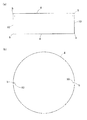
その複葉弁の一例を、本願に係る発明の一実施形態を示す図1、図2を参照して説明すると、弁箱1は、偏心弁体5を有する弁棒6の軸方向と直交し流路Sの軸方向aに沿う面を分割面(以下、割面11という)として、左右方向に二分割した構造である。その二分割した弁箱1の一方の割面11には、割面止水用パッキン10を嵌めるための溝12が形成されている。この溝12にパッキン10を嵌めてから、二分割した弁箱1の割面11を合わせて弁箱1を組み立て、割面11を合わせた部分(弁箱分割部)からの漏水を防いでいる。
An example of the bi-leaf valve will be described with reference to FIGS. 1 and 2 showing an embodiment of the invention according to the present application. The
また、図2に示すように、この種の複葉弁Vなどの弁は各種の配管Pに介設され、その接続は相互のフランジ7a、7bをボルト・ナットによって締結するのが一般的である。その時、その接続部からの漏水を防止するため、両フランジ7a、7b間にはその全周に亘る円状の接続部止水用パッキン4が介在される。
Further, as shown in FIG. 2, valves such as this type of bi-leaf valve V are interposed in various pipes P, and the connection thereof is generally made by fastening the
上記円状の接続部止水用パッキン4の側面と割面止水用パッキン10の両端面は当接して(本願図4、図5参照)、止水性を担保する必要がある。このため、従来では、図6に示すように、当接面(当接部)bを接着剤で接合した一体物としたり、接続部止水用パッキン4を半円状の対のものとし、その対の半円状の接続部止水用パッキン4と割面止水用パッキン10の接続部の間にT字状の接続用パッキンを介在し、そのT字状接続用パッキンのフランジ部分端面を両対の接続部止水用パッキン4の端面にそれぞれ接着し、ウェブ部分端面を割面止水用パッキン10の端面に接着したりして一体としたものがある。
The side surfaces of the circular connection portion waterproofing packing 4 and both end surfaces of the split surface waterproofing packing 10 need to be in contact with each other (see FIGS. 4 and 5 of the present application) to ensure waterproofness. For this reason, conventionally, as shown in FIG. 6, the contact surface (contact portion) b is formed as an integral member joined by an adhesive, or the connection portion
この一体物のパッキン4、10を上記弁箱1に組み込むには、二分割した弁箱1を組み立てる際、パッキン4、10を割面11の溝12及びフランジ7aの溝3に嵌めつつ、組み立てることとなる。
この組み立て時にパッキン4、10を傷つけたり、組み立て後の水圧試験で止水部(パッキン介在部)で漏水があったり、配管作業中にパッキン4を傷つけたりすると、そのパッキン4、10をセットし直したり、交換する必要がある。
このとき、接続部止水用パッキン4と割面止水用パッキン10が一体物であるため、弁箱1を解体し、各パッキン4、10をセットし直したり、新たなパッキン4、10を組み込んだりして組み直す必要があった。
この組み直しは煩雑であり、作業性の低下となってコスト的にも問題となっている。
In order to incorporate the integrated
If the
At this time, since the connection part waterproofing packing 4 and the split
This reassembly is complicated, and the workability is reduced, resulting in a cost problem.
この発明は、以上の状況の下、パッキン4、10のセット直しや、交換に際して、弁箱1を組み直す(解体する)必要を無くすることを課題とする。
An object of the present invention is to eliminate the necessity of reassembling (disassembling) the
上記課題を達成するために、この発明は、接続部止水用パッキンの側面と割面止水用パッキンの両端面とを圧力を持った当接によって止水するようにしたのである。
このように、圧力を持った当接によって止水すれば、セットし直し等の不適切なパッキンのみを外すことで、セット直しや交換ができるため、その作業性が向上する。
In order to achieve the above object, according to the present invention, the side surface of the packing for waterproofing the connection portion and both end surfaces of the packing for waterproofing the split surface are stopped by pressure contact.
In this way, if the water is stopped by abutting with pressure, only the inappropriate packing such as resetting is removed, so that resetting and replacement can be performed, thereby improving workability.
具体的には、流路の軸方向に沿う割面で分割可能な弁箱と、前記割面にその前記軸方向全長に亘って形成された割面止水用パッキン溝と、弁箱の流路方向の両側にフランジと、その両フランジの表面全周に亘って形成された配管等の他の部材との接続部止水用パッキン溝と、割面止水用パッキン溝に嵌められる割面止水用パッキンと、接続部止水用パッキン溝に嵌められる接続部止水用パッキンと、を有する弁箱構造であって、前記接続部止水用パッキンと割面止水用パッキンとは別物からなって切り離し可能であり、その接続部止水用パッキンの側面と割面止水用パッキンの両端面は圧力を持って当接し、その割面止水用パッキンの当接部の嵌った割面止水用パッキン溝の部分は、当該割面止水用パッキンの当接部のうちの前記割面止水用パッキン溝に嵌った部分と同一大きさの断面形状となっている構成を採用したのである。
この構成において、上記「同一大きさの断面形状」は、厳格に同一大きさの断面形状である必要はなく、割面止水用パッキンが割面止水用パッキン溝にピッタリ嵌って、接続部止水用パッキンの側面と割面止水用パッキンの両端面の当接部が大きな接触面積を持って圧接して有効に止水する、この発明の作用効果を発揮し得る限りにおいて変更し得る大きさや断面形状を含むものとする。
Specifically, a valve box that can be divided by a split surface along the axial direction of the flow path, a split surface water stopping groove formed on the split surface over the entire length in the axial direction, Flanges on both sides in the road direction, packing grooves for connecting water to other members such as piping formed over the entire surface of both flanges, and a split surface fitted in the split water sealing grooves. A valve box structure having a water stop packing and a connection part water stop packing fitted in the connection part water stop packing groove, wherein the connection part water stop packing and the split surface water stop packing are different from each other. consist a separable, both end surfaces of the side surface and the cut surface waterproof packing of the connection portion waterproofing gasket abuts with pressure, split that fits the abutment of the cut surface waterproof packing The part of the packing groove for surface water stop is the part of the contact surface Than it is adopted the configuration in which a portion of the same size of the sectional shape fitted to Kkin groove.
In this configuration, the “cross-sectional shape of the same size” does not need to be strictly a cross-sectional shape of the same size. The contact portions between the side surfaces of the water-stop packing and both end surfaces of the split water-stop packing press against each other with a large contact area to effectively stop water, and may be changed as long as the effects of the present invention can be exerted. It shall include the size and cross-sectional shape.
このように構成すると、割面止水用パッキンの当接部の嵌った割面止水用パッキン溝の部分は、当該割面止水用パッキン10の当接部のうちの前記割面止水用パッキン溝に嵌った部分と同一大きさの断面形状となっているため、割面止水用パッキンの当接部は割面止水用パッキン溝にピッタリ嵌り、接続部止水用パッキンの側面と割面止水用パッキンの両端面とを圧力を持って当接しても、その当接した端部が溝内で動き難い。このため、接続部止水用パッキンの側面と割面止水用パッキンの両端面の当接部が大きな接触面積を持って圧接して有効に止水する。
このとき、両パッキンの断面形状は丸形、角形等が考えられるが、割面止水用パッキンは断面四角形とするのが好ましい。断面四角形であると、板ゴムからの切断で製作できて安価なものとし得るとともに、溝が断面四角形の場合、その溝に割面止水用パッキンがピッタリ嵌って、上記パッキンの当接した端部の溝内での動きをより有効に抑制する。
また、上記割面止水用パッキンにその当接部の長さ方向内側に横方向に突出する突起部を設けて、その突起部を上記割面止水用パッキン溝から枝分かれした横方向の枝溝に嵌るようにすれば、上記接続部止水用パッキンの側面から割面止水用パッキン端面が押された際、その当接した端部が溝内で動くことをより有効に抑制する。
With such a configuration, the portion of the split surface water stop packing groove in which the contact portion of the split surface water stop packing is fitted is the cut surface water stop portion of the contact portion of the split surface water stop packing 10. The cross-sectional shape is the same size as the part fitted in the packing groove, so the abutting part of the split face waterproof packing fits perfectly into the split face waterproof packing groove, and the side of the connecting part waterproof packing Even if the both ends of the split water-stop packing are brought into contact with pressure, the abutted ends are unlikely to move in the groove. For this reason, the contact portions between the side surfaces of the connection portion waterproofing packing and both end surfaces of the split surface waterproofing packing have a large contact area and press-contact to effectively stop water.
At this time, the cross-sectional shape of both packings may be a round shape, a square shape, or the like. If the cross section is square, it can be manufactured by cutting from plate rubber and it can be inexpensive, and if the groove has a square cross section, the split surface waterproof packing fits perfectly into the groove, and the abutted end of the packing The movement of the part in the groove is more effectively suppressed.
Further, the split water-stop packing is provided with a protrusion protruding laterally inside the lengthwise direction of the abutting portion, and the protrusion is laterally branched from the split water-stop packing groove. When the groove is fitted in the groove, when the end face of the split surface waterproofing packing is pressed from the side surface of the connecting portion waterproofing packing, the contacted end thereof is more effectively prevented from moving in the groove.
この発明は以上のように構成して、接続部止水用パッキンの側面と割面止水用パッキンの両端面とを圧力を持った当接によって止水するようにしたので、セットし直し等の不適切なパッキンのみを外すことで、セット直しや交換ができるため、その作業性が向上する。 The present invention is configured as described above, and the side face of the seal for waterproofing of the connection part and both end faces of the seal for waterproofing of the split face are stopped by pressurized abutment. By removing only the inappropriate packing, the set can be reset or replaced, so that the workability is improved.
図1〜図5にこの発明の一実施形態に係る複葉弁Vを示し、この複葉弁Vも、従来と同様に、流路Sの軸方向aに沿う割面11、11で分割可能な弁箱1と、前記割面11の一方にその軸方向a全長に亘って形成された割面止水用パッキン溝12と、弁箱1の前記軸方向a両側のフランジ7a、7aと、その両フランジ7a、7aの表面(図2において左右側表面)全周に亘って形成された配管P等の他の部材との接続部止水用パッキン溝3と、割面止水用パッキン溝12に嵌められる割面止水用パッキン10と、接続部止水用パッキン溝3に嵌められる接続部止水用パッキン4とを有する。その接続部止水用パッキン4と割面止水用パッキン10とは別物からなって切り離し可能である。図中、5は弁体、6は弁軸、8は弁座であって、この実施形態は、弁体5と弁軸6は一体となっているが、別部材とすることができる。
1 to 5 show a double leaf valve V according to one embodiment of the present invention. This double leaf valve V is also a valve which can be divided by
弁箱1の内径及び材料は、例えば、3500mm、SS400等であり、接続部止水用パッキン溝3は、例えば、深さ:6.8mm、幅:12.5mmの断面四角状である。その溝3に嵌める接続部止水用パッキン4は、例えば、ニトリルゴム(NBR)等からなる断面丸状の径:10mmのOリングである。
割面止水用パッキン溝12は、断面四角状であって、その溝幅は全長に亘って同一、例えば12.5mmとし、深さ:6.8mmとしている。図中、12a、12bは下記突起部13a、枝部13bが嵌る溝12から分岐した枝溝である。
The inner diameter and the material of the
The dividing
割面止水用パッキン10は、例えば、ニトリルゴム(NBR)等からなる全長に亘り断面四角状、例えば、幅:12.5mm、厚み(図5の表裏面方向の厚み):8mmで、その断面四隅を面取りした形状であって、両端部の突起部13aと一端側の枝部13bとが一体に形成され(有し)、枝部13bにも突起部13aを有している。枝部13bの先端は、弁座8に当接してシールする(その当接面を水密にする)。
この割面止水用パッキン10の突起部13aから先部分(当接部)10aに対し、突起部13a、13aの間10bはその幅が狭くなっており、例えば、前者10a:12.5mm、後者10b:10.5mmとしている。このため、この割面止水用パッキン10を割面止水用パッキン溝12に嵌めると、両端部分(当接部)10a、10aは溝12にピッタリ嵌るが、両突起部13a、13aの間部分10bは少し隙間をもって嵌ることとなる。
The split-surface water-
The width between the
この割面止水用パッキン10を割面止水用パッキン溝12に嵌めると、例えば、同パッキン溝12が深さ:6.8mm、同パッキン10が厚み:8mmであることから、同パッキン10のつぶし代:1.2(8−6.8)mmとなって、同パッキン10は十分な密着力をもって同パッキン溝12にピッタリ嵌め込まれて止水する。
When this packing 10 for water blocking is fitted into the packing
また、割面止水用パッキン10の横長さ(図2において左右方向長さ)は割面止水用パッキン溝12の横長さより短く設定されている。このため、溝12にパッキン10が嵌ると、その溝12の両端には空隙が生じる。この空隙に上記接続部止水用パッキン溝3の一部が位置して(通って)いる。このため、溝12にパッキン10が嵌り、溝3にパッキン4が嵌ると、図4に示すように、接続部止水用パッキン4、4の側面と割面止水用パッキン10の両端面は当接する。
Further, the lateral length (length in the left-right direction in FIG. 2) of the split surface water stop packing 10 is set shorter than the horizontal length of the split surface water
この状態で、分割された弁箱1が割面11、11を合わせて組み立てられると、接続部止水用パッキン4の側面と割面止水用パッキン10の両端面は圧力を持って当接し、その割面止水用パッキン10の当接部10aの嵌った割面止水用パッキン溝12の部分は、当該当接部10aのうちの割面止水用パッキン溝12に嵌った部分と同一大きさの断面形状となる(割面止水用パッキン10が割面止水用パッキン溝12にピッタリ嵌る)。
In this state, when the divided
この実施形態の複葉弁Vは以上の構成であり、従来と同様に、割面11の割面止水用パッキン溝12に割面止水用パッキン10を嵌めた後、半割の弁箱1を割面11で重ねてボルト・ナット締結によって弁箱1を組み立てる。このとき、弁体5等を組み込み、接続部止水用パッキン4はその溝3に嵌めていても良いが、その嵌め込みは組み立て後でも良い。
この弁箱1の組み立て時、パッキン10のセットし直しが生じたり、破損によって交換が必要になったりすれば、弁箱1を解体してそれらを行う。
The bi-leaf valve V of this embodiment has the above-described configuration. As in the conventional case, the split face water-stop packing 10 is fitted into the split face water-
At the time of assembling the
この弁Vを各種の配管Pに介設する場合、従来と同様に、相互のフランジ7a、7bをボルト・ナットによって締結する。そのとき、フランジ7a、7bの締結によって、接続部止水用パッキン4が圧縮されて両フランジ7a、7b間を密封(止水)するとともに、接続部止水用パッキン4、4の側面が割面止水用パッキン10の両端面に圧力をもって当接する。その当接は、割面止水用パッキン10の両端部10aが溝12にピッタリ嵌り、突起部13aによって長さ方向の移動が阻止されるため、その両端部10aは溝12内で動かず、圧力を持った状態を維持するため、有効な止水効果を発揮するとともに維持する。
この介設時、フランジ7a、7bの締結作業が適切でない等によって、パッキン4をセットし直したり、交換したりする必要が生じれば、弁Vと配管Pとの接続を解除して、そのパッキン4のセットし直しをしたり、交換をしたりする。
When this valve V is interposed in various pipes P, the
At this time, if it is necessary to reset or replace the
なお、上記実施形態は複葉弁であったが、複葉弁(複葉型のバタフライ弁)に限らず、同じように、流路に沿う面で分割可能なバタフライ弁等であれば、この発明を採用し得ることは言うまでもない。
また、割面11の方向は上下方向に限らず、左右方向等と任意である。
このように、今回開示された実施の形態はすべての点で例示であって制限的なものではないと考えられるべきである。この発明の範囲は、特許請求の範囲によって示され、特許請求の範囲と均等の意味および範囲内でのすべての変更が含まれることが意図される。
Although the above-described embodiment is a bi-leaf valve, the present invention is not limited to a bi-leaf valve (a bi-leaf type butterfly valve). It goes without saying that it can be done.
Further, the direction of the
Thus, the embodiments disclosed this time are to be considered in all respects as illustrative and not restrictive. The scope of the present invention is defined by the terms of the claims, and is intended to include any modifications within the scope and meaning equivalent to the terms of the claims.
1 弁箱
3 接続部止水用パッキン溝
4 接続部止水用パッキン
5 弁体
6 弁軸
7a 弁箱側フランジ
7b 配管側フランジ
8 弁座
10 割面止水用パッキン
10a 割面止水用パッキンの端部(当接部)
11 割面
12 割面止水用パッキン溝
13a 割面止水用パッキンの突起部
13b 同枝部
V 複葉弁
S 流路
a 流路の軸方向
b 接続部止水用パッキンと割面止水用パッキンの接続部
1 Valve box
3 Packing groove for waterproofing of
Claims (2)
上記割面(11)に上記軸方向(a)全長に亘って形成された割面止水用パッキン溝(12)と、
弁箱(1)の上記軸方向(a)両側のフランジ(7a)と、
その両フランジ(7a)の表面全周に亘って形成された接続部止水用パッキン溝(3)と、
上記割面止水用パッキン溝(12)に嵌められる割面止水用パッキン(10)と、
上記接続部止水用パッキン溝(3)に嵌められる配管(P)等の他の部材との接続部止水用パッキン(4)と、
を有する弁箱構造であって、
上記接続部止水用パッキン(4)と割面止水用パッキン(10)とは別物からなって切り離し可能であり、その接続部止水用パッキン(4)の側面と割面止水用パッキン(10)の両端面は圧力を持って当接し、その割面止水用パッキン(10)の当接部(10a)の嵌った割面止水用パッキン溝(12)の部分は、当該割面止水用パッキン(10)の当接部(10a)のうちの前記割面止水用パッキン溝(12)に嵌った部分と同一大きさの断面形状となっているとともに、その割面止水用パッキン(10)は前記当接部(10a)の長さ方向内側に横方向に突出する突起部(13a)を有して、その突起部(13a)が上記割面止水用パッキン溝(12)から枝分かれした横方向の枝溝(12a)に嵌っている弁箱構造。 A valve box (1) that can be divided by a split surface (11) along the axial direction (a) of the flow path (S);
A split surface water-stop packing groove (12) formed over the entire length of the split surface (11) in the axial direction (a);
Flanges (7a) on both sides in the axial direction (a) of the valve box (1);
A sealing groove (3) for waterproofing the connection portion, which is formed over the entire surface of the two flanges (7a);
A split surface waterproof packing (10) fitted in the split surface waterproof packing groove (12);
A watertight gasket (4) for connection with another member such as a pipe (P) fitted in the watertight groove (3) for watertight connection;
A valve box structure having
The connecting part waterproofing packing (4) and the split face waterproofing packing (10) are separate and can be separated, and the side face of the connecting part waterproofing packing (4) and the split face waterproofing packing are provided. Both end faces of (10) abut against each other with pressure. The contact portion (10a) of the surface waterproof packing (10) has the same cross-sectional shape as the portion fitted in the split surface waterproof packing groove (12), and the split surface stop. The water packing (10) has a protrusion (13a) projecting laterally inside the longitudinal direction of the contact part (10a), and the protrusion (13a) is provided in the split surface water stopping groove. A valve box structure fitted in a lateral branch groove (12a) branched from (12).
Priority Applications (1)
| Application Number | Priority Date | Filing Date | Title |
|---|---|---|---|
| JP2017040386A JP6672201B2 (en) | 2017-03-03 | 2017-03-03 | Valve box structure |
Applications Claiming Priority (1)
| Application Number | Priority Date | Filing Date | Title |
|---|---|---|---|
| JP2017040386A JP6672201B2 (en) | 2017-03-03 | 2017-03-03 | Valve box structure |
Publications (2)
| Publication Number | Publication Date |
|---|---|
| JP2018146010A JP2018146010A (en) | 2018-09-20 |
| JP6672201B2 true JP6672201B2 (en) | 2020-03-25 |
Family
ID=63591047
Family Applications (1)
| Application Number | Title | Priority Date | Filing Date |
|---|---|---|---|
| JP2017040386A Active JP6672201B2 (en) | 2017-03-03 | 2017-03-03 | Valve box structure |
Country Status (1)
| Country | Link |
|---|---|
| JP (1) | JP6672201B2 (en) |
Families Citing this family (1)
| Publication number | Priority date | Publication date | Assignee | Title |
|---|---|---|---|---|
| JP7762756B2 (en) * | 2024-03-21 | 2025-10-30 | 株式会社栗本鐵工所 | Valve box structure and pipe structure |
Family Cites Families (3)
| Publication number | Priority date | Publication date | Assignee | Title |
|---|---|---|---|---|
| JPS55168756U (en) * | 1979-05-23 | 1980-12-04 | ||
| JPS58148378U (en) * | 1982-03-31 | 1983-10-05 | 株式会社東芝 | butterfly valve |
| JP5886672B2 (en) * | 2012-03-30 | 2016-03-16 | 株式会社栗本鐵工所 | Seal structure of valve box division |
-
2017
- 2017-03-03 JP JP2017040386A patent/JP6672201B2/en active Active
Also Published As
| Publication number | Publication date |
|---|---|
| JP2018146010A (en) | 2018-09-20 |
Similar Documents
| Publication | Publication Date | Title |
|---|---|---|
| US8621741B2 (en) | 4-way compression grooved coupling | |
| KR101426855B1 (en) | Split mechanical seal | |
| CN204477341U (en) | For the Sealing of rotary valve | |
| US20110266797A1 (en) | Seal Ring And Joint | |
| US20140175319A1 (en) | Multi-section valve bodies having face seals | |
| US20140034861A1 (en) | Sealing system for industrial gate valves and gate valve comprising such a system | |
| KR20110128847A (en) | Gate valve with integral support members | |
| TW201723370A (en) | Sprung seal retainer | |
| US3345078A (en) | Seal assembly | |
| JP6672201B2 (en) | Valve box structure | |
| US8459653B2 (en) | Seal assembly segment joints | |
| JP5021941B2 (en) | Valve with valve seat with lip | |
| JP7426775B2 (en) | Sealed structure | |
| JP2009052571A (en) | Pipe-connecting structure | |
| JP5886672B2 (en) | Seal structure of valve box division | |
| CN205715716U (en) | Low temperature stop valve | |
| KR20240010017A (en) | Cocks for valves and valves containing such cocks | |
| JP7162343B2 (en) | Leakage prevention device for flange joints | |
| JP6490451B2 (en) | Leakage prevention device for flange joints | |
| JP7497845B2 (en) | Leak Repair Equipment | |
| JP7762756B2 (en) | Valve box structure and pipe structure | |
| KR20060094864A (en) | Butterfly valve to control the compression force of the seat | |
| KR101555583B1 (en) | Reverse pipe interface device | |
| JP6725931B2 (en) | Lining type butterfly valve | |
| JP7408328B2 (en) | gasket |
Legal Events
| Date | Code | Title | Description |
|---|---|---|---|
| A621 | Written request for application examination |
Free format text: JAPANESE INTERMEDIATE CODE: A621 Effective date: 20181127 |
|
| A977 | Report on retrieval |
Free format text: JAPANESE INTERMEDIATE CODE: A971007 Effective date: 20190815 |
|
| A131 | Notification of reasons for refusal |
Free format text: JAPANESE INTERMEDIATE CODE: A131 Effective date: 20190820 |
|
| A521 | Written amendment |
Free format text: JAPANESE INTERMEDIATE CODE: A523 Effective date: 20191021 |
|
| TRDD | Decision of grant or rejection written | ||
| A01 | Written decision to grant a patent or to grant a registration (utility model) |
Free format text: JAPANESE INTERMEDIATE CODE: A01 Effective date: 20200204 |
|
| A61 | First payment of annual fees (during grant procedure) |
Free format text: JAPANESE INTERMEDIATE CODE: A61 Effective date: 20200304 |
|
| R150 | Certificate of patent or registration of utility model |
Ref document number: 6672201 Country of ref document: JP Free format text: JAPANESE INTERMEDIATE CODE: R150 |