JP6671853B2 - Power conversion device and industrial machine using the same - Google Patents
Power conversion device and industrial machine using the same Download PDFInfo
- Publication number
- JP6671853B2 JP6671853B2 JP2015067372A JP2015067372A JP6671853B2 JP 6671853 B2 JP6671853 B2 JP 6671853B2 JP 2015067372 A JP2015067372 A JP 2015067372A JP 2015067372 A JP2015067372 A JP 2015067372A JP 6671853 B2 JP6671853 B2 JP 6671853B2
- Authority
- JP
- Japan
- Prior art keywords
- converter
- power supply
- link
- power
- voltage
- Prior art date
- Legal status (The legal status is an assumption and is not a legal conclusion. Google has not performed a legal analysis and makes no representation as to the accuracy of the status listed.)
- Active
Links
Images


Description
本発明は、電力変換装置に関する。 The present invention relates to a power converter.
クレーンやハイブリッドショベルなどの産業機械には、電力変換装置が用いられる。図1は、産業機械10の電気系統を示すブロック図である。産業機械は、電力変換装置100R、蓄電デバイス200、発電機202、インバータ204、モータ206を備える。
Power conversion devices are used for industrial machines such as cranes and hybrid shovels. FIG. 1 is a block diagram illustrating an electric system of the
インバータ204は、力行運転時にモータ206に電力を供給し、回転させる。またモータ206の回生運転時には、インバータ204は、モータ206からの電流を整流し、電力変換装置100Rに供給する。蓄電デバイス200は、リチウムイオン電池などの2次電池、あるいは電気二重層キャパシタなどである。発電機202は、発電機202は、エンジンの回転に応じた電力を発生する。
The
電力変換装置100Rは、蓄電デバイス200、発電機202、インバータ204の間に設けられ、それらの間で電圧レベルを適切に変換する。電力変換装置100Rは、DCリンクバス102、バッテリコンバータ104、エンジンコンバータ120、平滑コンデンサC1、放電抵抗R1を備える。
平滑コンデンサC1は、DCリンクバス102に接続される。エンジンコンバータ120の降圧側端子は、発電機202と接続され、昇圧側端子はDCリンクバス102と接続される。エンジンコンバータ120は、発電機202からの直流電圧を昇圧し、DCリンクバス102の電圧(DCリンク電圧)を所定レベルに安定化する。
The smoothing capacitor C1 is connected to the
バッテリコンバータ104の降圧側端子は蓄電デバイス200と接続され、昇圧側端子はDCリンクバス102と接続される。バッテリコンバータ104は、モータ206の力行運転時には、昇圧コンバータとして動作し、蓄電デバイス200の電圧VBATを昇圧する。バッテリコンバータ104は、モータ206の回生運転時には、降圧コンバータとして動作し、DCリンクバス102からエネルギーを蓄電デバイス200に回収し、DCリンク電圧VDCを安定化させる。
The step-down side terminal of the
用途によっては、DCリンク電圧VDCは非常に高圧(たとえば数百V以上)となる。したがって電力変換装置100Rの非動作時において、平滑コンデンサC1の電荷が残留していると、DCリンク電圧VDCの高圧が維持されるため危険である。
In some applications, the DC link voltage VDC is very high (eg, several hundred volts or more). Therefore, when the
そこで平滑コンデンサC1と並列に、放電抵抗R1が挿入される。電力変換装置100Rの動作が停止すると、平滑コンデンサC1の電荷は放電抵抗R1を介して放電され、DCリンク電圧VDCが安全電圧VSAFE(たとえば60V以下)まで低下する。また放電抵抗R1は、バッテリコンバータ104の停止時において、回生運転となりインバータ204から過剰な電力が供給されたときに、平滑コンデンサC1が許容電圧レベルを超えるのを抑制する。
Therefore, a discharge resistor R1 is inserted in parallel with the smoothing capacitor C1. When the operation of
一方、放電抵抗R1は、電力変換装置100Rの動作中においても、常に平滑コンデンサC1の放電経路を形成している。したがって放電抵抗R1によって常に無駄な電力(P=R×IDIS 2=VDC 2/R)が消費されることとなり、省エネ化の要請に反する。
On the other hand, discharge resistor R1 always forms a discharge path of smoothing capacitor C1 even during operation of
本発明は係る課題に鑑みてなされたものであり、そのある態様の例示的な目的のひとつは、消費電力を低減した産業機械用の電力変換装置の提供にある。 SUMMARY An advantage of some aspects of the invention is to provide a power conversion device for industrial machines with reduced power consumption.
本発明のある態様は、モータ、インバータおよび蓄電デバイスを備える産業機械に使用される電力変換装置に関する。電力変換装置は、DCリンクバスと、DCリンクバスに接続される平滑コンデンサと、その昇圧側端子がDCリンクバスと接続され、その降圧側端子が前記蓄電デバイスと接続され、リアクトルおよびスイッチング素子を含む第1昇降圧コンバータと、平滑コンデンサと並列な経路に、直列に設けられる放電抵抗および放電スイッチと、DCリンクバスに発生するDCリンク電圧を受け、第1電源電圧を生成する内部制御電源と、内部制御電源からの第1電源電圧が供給され、放電スイッチを制御する放電コントローラと、を備える。 One embodiment of the present invention relates to a power conversion device used for an industrial machine including a motor, an inverter, and a power storage device. The power converter includes a DC link bus, a smoothing capacitor connected to the DC link bus, a step-up terminal connected to the DC link bus, a step-down terminal connected to the power storage device, and a reactor and a switching element. A first step-up / down converter, a discharge resistor and a discharge switch provided in series on a path parallel to the smoothing capacitor, and an internal control power supply for receiving a DC link voltage generated on a DC link bus and generating a first power supply voltage. A discharge controller supplied with a first power supply voltage from an internal control power supply and controlling a discharge switch.
この態様によると、通常の動作時には放電スイッチをオフすることで、放電経路を遮断できるため、無駄な消費電力を低減できる。また放電スイッチを制御する放電コントローラの電源を、DCリンク電圧にもとづいて生成することとしているため、放電スイッチをオンすべき期間、つまりDCリンク電圧がある程度高い状態では、放電コントローラを確実に動作させることができる。これにより、DCリンク電圧を安全電圧以下まで確実に低下させることができる。 According to this aspect, the discharge path can be cut off by turning off the discharge switch during normal operation, so that useless power consumption can be reduced. Further, since the power supply of the discharge controller for controlling the discharge switch is generated based on the DC link voltage, the discharge controller is reliably operated during the period when the discharge switch is to be turned on, that is, in a state where the DC link voltage is somewhat high. be able to. As a result, the DC link voltage can be reliably reduced to the safe voltage or less.
電力変換装置は、外部から電源供給され、第2電源電圧を生成する外部制御電源をさらに備えてもよい。放電コントローラは、第1電源電圧、第2電源電圧の一方を受けて動作可能であってもよい。
放電コントローラへの電源供給を多重化することで、より確実に放電スイッチを制御できる。
The power converter may further include an external control power supply that is externally supplied with power and generates the second power supply voltage. The discharge controller may be operable by receiving one of the first power supply voltage and the second power supply voltage.
By multiplexing the power supply to the discharge controller, the discharge switch can be controlled more reliably.
電力変換装置は、その昇圧側端子がDCリンクバスと接続され、その降圧側端子がエンジンを動力源とする発電機と接続される第2昇降圧コンバータをさらに備えてもよい。 The power converter may further include a second step-up / step-down converter having a step-up side terminal connected to the DC link bus and a step-down side terminal connected to a generator using the engine as a power source.
放電コントローラは、第1昇降圧コンバータの停止状態においてモータが回生運転するときに、放電スイッチをオンしてもよい。
これにより、DCリンク電圧が過電圧となるのを防止できる。
The discharge controller may turn on the discharge switch when the motor performs the regenerative operation in the stop state of the first buck-boost converter.
This can prevent the DC link voltage from becoming overvoltage.
本発明の別の態様は産業機械に関する。産業機械は、モータ、インバータおよび蓄電デバイスと、上述のいずれかの電力変換装置と、を備える。 Another embodiment of the present invention relates to an industrial machine. The industrial machine includes a motor, an inverter, and a power storage device, and any one of the power conversion devices described above.
なお、以上の構成要素の任意の組み合わせや本発明の構成要素や表現を、方法、装置、システムなどの間で相互に置換したものもまた、本発明の態様として有効である。 It should be noted that any combination of the above-described components, and any replacement of the components and expressions of the present invention between methods, apparatuses, systems, and the like are also effective as embodiments of the present invention.
本発明によれば、電力変換装置の消費電力を低減できる。 ADVANTAGE OF THE INVENTION According to this invention, the power consumption of a power converter can be reduced.
以下、本発明を好適な実施の形態をもとに図面を参照しながら説明する。各図面に示される同一または同等の構成要素、部材、処理には、同一の符号を付するものとし、適宜重複した説明は省略する。また、実施の形態は、発明を限定するものではなく例示であって、実施の形態に記述されるすべての特徴やその組み合わせは、必ずしも発明の本質的なものであるとは限らない。 Hereinafter, the present invention will be described based on preferred embodiments with reference to the drawings. The same or equivalent components, members, and processes shown in each drawing are denoted by the same reference numerals, and the repeated description will be omitted as appropriate. In addition, the embodiments do not limit the invention, but are exemplifications, and all features and combinations thereof described in the embodiments are not necessarily essential to the invention.
本明細書において、「部材Aが、部材Bと接続された状態」とは、部材Aと部材Bが物理的に直接的に接続される場合のほか、部材Aと部材Bが、それらの電気的な接続状態に実質的な影響を及ぼさない、あるいはそれらの結合により奏される機能や効果を損なわせない、その他の部材を介して間接的に接続される場合も含む。
同様に、「部材Cが、部材Aと部材Bの間に設けられた状態」とは、部材Aと部材C、あるいは部材Bと部材Cが直接的に接続される場合のほか、それらの電気的な接続状態に実質的な影響を及ぼさない、あるいはそれらの結合により奏される機能や効果を損なわせない、その他の部材を介して間接的に接続される場合も含む。
In this specification, “the state in which the member A is connected to the member B” means that the member A and the member B are physically directly connected, and that the member A and the member B It does not substantially affect the actual connection state, or does not impair the function or effect exerted by the combination thereof, and also includes the case where the connection is made indirectly via another member.
Similarly, “the state in which the member C is provided between the member A and the member B” means that the member A and the member C or the member B and the member C are directly connected, It does not substantially affect the actual connection state, or does not impair the function or effect exerted by the combination thereof, and also includes the case where the connection is made indirectly via another member.
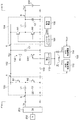
図2は、実施の形態に係る電力変換装置100のブロック図である。電力変換装置100は、図1に類する電気系統を産業機械に使用される。後述のように産業機械としては、クレーンやハイブリッドショベルが好適である。電力変換装置100は、1次側Pに接続される発電機202、2次側Sに接続される蓄電デバイス200、ならびにDCリンクバス102に接続されるインバータおよびモータ(不図示、3次側と称する)との間で、エネルギーを授受可能に構成される。
FIG. 2 is a block diagram of the
1次側Pには、たとえばエンジンにより駆動される発電機202と、発電機202が発生する交流電圧を整流する整流回路203が接続される。また2次側Sには、蓄電デバイス200が接続される。蓄電デバイス200は、たとえばリチウムイオンなどの二次電池、あるいは電気二重層キャパシタなどのコンデンサである。
Connected to the primary side P is, for example, a
電力変換装置100は、DCリンクバス102、平滑コンデンサC1、第1の昇降圧コンバータであるバッテリコンバータ104、コンバータコントローラ106、制御電源108、放電抵抗R1、放電スイッチSW1、放電コントローラ112、内部制御電源110、外部制御電源114、第2昇降圧コンバータであるエンジンコンバータ120を備える。
The
平滑コンデンサC1はDCリンクバス102に接続され、DCリンクバス102の電圧(DCリンク電圧)VDCを平滑・安定化する。
A smoothing capacitor C1 is connected to the
エンジンコンバータ120は、その昇圧側端子AがDCリンクバス102と接続され、その降圧側端子Bが整流回路203に接続されている。エンジンコンバータ120は、整流回路203からの直流電圧VPを受け、それを昇圧して、DCリンクバス102のDCリンク電圧VDCを所定の目標電圧VREFに安定化する。エンジンコンバータ120は、リアクトルL1およびスイッチング素子M1、M2、平滑コンデンサC2を含む。エンジンコンバータ120のスイッチング素子M1、M2は、コンバータコントローラ122によって制御される。
The
バッテリコンバータ104は、その昇圧側端子AがDCリンクバス102と接続され、その降圧側端子Bが蓄電デバイス200と接続される。バッテリコンバータ104は、エンジンコンバータ120と同様に構成される。平滑コンデンサC2は省略してもよい。
The
コンバータコントローラ106は、バッテリコンバータ104のスイッチング素子M1、M2を制御する。コンバータコントローラ106は、制御電源108が生成する電源電圧VDD3を受けて動作する。
コンバータコントローラ106は、モータの力行運転時において、昇圧コンバータとして動作し、蓄電デバイス200の電圧VBATを昇圧してDCリンク電圧VDCを安定化する。つまり、エンジンコンバータ120からインバータへの供給をアシストする。反対にコンバータコントローラ106は、モータの回生運転時には、降圧コンバータとして動作し、DCリンクバス102からエネルギーを蓄電デバイス200に回収し、DCリンク電圧VDCを安定化させる。
放電抵抗R1および放電スイッチSW1は、平滑コンデンサC1と並列な経路に、言い換えればDCリンクバス102と接地ライン103の間に、直列に設けられる。内部制御電源110は、制御電源108とは別に設けられており、DCリンク電圧VDCを受け、第1電源電圧VDD1を生成する。
The discharge resistor R1 and the discharge switch SW1 are provided in series on a path parallel to the smoothing capacitor C1, in other words, between the
放電コントローラ112は、内部制御電源110からの第1電源電圧VDD1を受け、放電スイッチSW1を制御する。具体的には放電コントローラ112は、電力変換装置100の動作停止時に、放電スイッチSW1をオンする。また放電コントローラ112は、電力変換装置100の動作中であっても、図示しないインバータあるいはエンジンコンバータ120からのDCリンクバス102への電力供給が過剰であるときには、放電スイッチSW1をオンし、DCリンク電圧VDCのオーバーシュートを抑制してもよい。たとえばバッテリコンバータ104の停止状態においてモータが回生運転するときには、DCリンクバス102への電力供給が過剰となる。そこで放電コントローラ112は、バッテリコンバータ104の停止状態においてモータが回生運転するときに放電スイッチSW1をオンする。放電コントローラ112は、外部からの制御指令に応じて放電スイッチSW1を制御してもよいし、自らが、発電機202、バッテリコンバータ104、エンジンコンバータ120、インバータやモータ等の状態を監視し、監視結果に基づいて適応的に放電スイッチSW1を制御してもよい。
The discharge controller 112 receives the first power supply voltage VDD1 from the internal
外部制御電源114は、外部からの電源電圧VEXTの供給を受け、第2電源電圧VDD2を生成する。外部電源電圧VEXTは、整流回路203が生成する直流電圧VPであってもよいし、外部から与えられる商用交流電圧であってもよく、その起源は問わない。
The external
放電コントローラ112には、第1電源電圧VDD1に加えて、第2電源電圧VDD2が供給可能であってもよい。たとえば放電コントローラ112は、ダイオードOR回路116を介して、2つの電源電圧VDD1,VDD2が供給され、それらのうち、電圧レベルの高い一方を電源として動作してもよい。
The discharge controller 112, in addition to the first power supply voltage V DD1, the second power supply voltage V DD2 may be capable of providing. For example, the discharge controller 112 may be supplied with two power supply voltages V DD1 and V DD2 via the diode OR
以上が電力変換装置100の構成である。続いてその動作を説明する。
図3は、図2の電力変換装置100の動作波形図である。ここでは外部制御電源114からの第2電源電圧VDD2は、放電コントローラ112に供給されておらず、放電コントローラ112には第1電源電圧VDD1が供給されるものとする。
The above is the configuration of the
FIG. 3 is an operation waveform diagram of the
時刻t0より前は、電力変換装置100が動作状態であり、DCリンク電圧VDCは、所定電圧VREFに安定化されている。この間、放電コントローラ112には、内部制御電源110により生成される第1電源電圧VDD1が供給され、放電スイッチSW1を制御可能となっている。時刻t0より前、放電コントローラ112は、放電スイッチSW1をオフしており、したがって放電経路130は遮断され、無駄な電力消費が抑制されている。
Before time t0,
時刻t0に発電機202が停止し、電力変換装置100も停止状態となる。電力変換装置100の停止状態では、エンジンコンバータ120、バッテリコンバータ104はいずれも停止する。これを契機として放電コントローラ112は、放電スイッチSW1をターンオンする。これにより平滑コンデンサC1の電荷が放電抵抗R1、放電スイッチSW1を含む放電経路130を介して放電され、DCリンク電圧VDCが時間とともに低下していく。やがて時刻t1に、DCリンク電圧VDCは、人体がDCリンクバス102に接触しても危害が及ばない安全電圧VSAFE以下となる。
At time t0, the
さらにDCリンク電圧VDCが低下すると、内部制御電源110が生成する第1電源電圧VDD1が低下し始め、時刻t2に第1電源電圧VDD1は、放電コントローラ112の最低動作電圧VLOWを下回る。時刻t2以降、放電コントローラ112は、放電スイッチSW1を制御不能となり、放電スイッチSW1のオン/オフ状態は不定となる。DCリンク電圧VDCは、安全電圧VSAFEより低い範囲で不定となり、リーク電流によって緩やかに低下していく。
When the DC link voltage V DC further decreases, the first power supply voltage V DD1 generated by the internal
以上が電力変換装置100の動作である。続いてその効果を説明する。
第1に、電力変換装置100によれば、通常の動作時には放電スイッチSW1をオフすることで、放電経路130を遮断できるため、無駄な消費電力を低減できる。
The above is the operation of the
First, according to the
第2に、放電スイッチSW1を制御する放電コントローラ112の電源を、DCリンク電圧VDCにもとづいて生成することとしている。ここで安全電圧VSAFEは60V程度であり、放電コントローラ112の最低動作電圧VLOWは、数Vからせいぜい20V程度である。したがって、内部制御電源110は、DCリンク電圧VDCが安全電圧VSAFEより低くなった後しばらくの間は、第1電源電圧VDD1を最低動作電圧VLOWよりも高い範囲に維持できる。
Second, the power supply of the discharge controller 112 that controls the discharge switch SW1 is generated based on the DC link voltage VDC . Here, the safe voltage V SAFE is about 60 V, and the minimum operating voltage V LOW of the discharge controller 112 is about several V to about 20 V at most. Thus, the internal
したがって、放電スイッチSW1をオンすべき期間、つまりDCリンク電圧VDCが安全電圧VSAFEより高い状態では、放電コントローラ112を確実に動作させることができる。これにより、DCリンク電圧VDCを安全電圧VSAFE以下まで確実に低下させることができる。 Therefore, during a period in which the discharge switch SW1 is to be turned on, that is, in a state where the DC link voltage VDC is higher than the safe voltage V SAFE , the discharge controller 112 can be reliably operated. Thus, the DC link voltage VDC can be reliably reduced to the safe voltage V SAFE or less.
第2の利点は、比較技術との対比によって明確となる。比較技術として、放電コントローラ112の電源電圧として、発電機202を起源とする電圧が供給される構成を考える。この構成では、発電機202の停止状態、つまり電力変換装置100の停止状態では、放電コントローラ112に電源電圧が供給されないため、放電スイッチSW1をターンオンすることができない。
The second advantage is clarified by comparison with the comparative technique. As a comparative technique, a configuration in which a voltage originating from the
別の比較技術として、放電コントローラ112の電源電圧として、商用交流電圧を起源とする電圧が供給される構成を考える。この構成では、商用交流電圧が供給されない状況では、放電コントローラ112に電源電圧が供給されないため、放電スイッチSW1をターンオンすることができない。 As another comparative technique, a configuration in which a voltage derived from a commercial AC voltage is supplied as a power supply voltage of the discharge controller 112 will be considered. In this configuration, when no commercial AC voltage is supplied, the power supply voltage is not supplied to the discharge controller 112, so that the discharge switch SW1 cannot be turned on.
これらの比較技術と対比して、実施の形態に係る電力変換装置100によれば、DCリンク電圧VDCを起源とした第1電源電圧VDD1を放電コントローラ112に供給することとしたため、確実に放電スイッチSW1をターンオンすることができる。
In contrast to these comparative techniques, according to the
(用途)
続いて、電力変換装置100の用途を説明する。電力変換装置100は、産業機械のひとつであるクレーンに使用される。クレーンは、図1に示す電気系統を有し、たとえばモータ206は、巻き上げ、巻き下げ用の主巻電動機に対応する。クレーンの巻き上げ時には、モータ206は力行運転をし、このときエンジンコンバータ120、バッテリコンバータ104は昇圧動作し、インバータに電力を供給する。一方、クレーンの巻き下げ時には、モータ206は回生運転となり、このときエンジンコンバータ120は停止し、バッテリコンバータ104は降圧動作し、回生エネルギーを蓄電デバイス200に回収する。
(Application)
Next, applications of the
電力変換装置100の動作中には、放電スイッチSW1をオフすることで消費電力が低減される。ただし電力変換装置100の動作であっても、巻き下げ動作中に、バッテリコンバータ104が故障あるいは制御下で停止した場合には、放電スイッチSW1をオンする。これによりDCリンクバス102に過大な電圧が生ずるのを防止でき、平滑コンデンサC1などの回路部品を保護できる。
During the operation of the
別の実施の形態において、電力変換装置100は、産業機械のひとつであるハイブリッドショベルに使用される。ハイブリッドショベルも図1に示す電気系統を有し、たとえばモータ206は、上部旋回体を回転させる旋回モータに対応する。旋回時には、モータ206は力行運転をし、このときエンジンコンバータ120、バッテリコンバータ104は昇圧動作し、インバータに電力を供給する。一方、旋回のブレーキ時には、モータ206は回生運転となり、このときエンジンコンバータ120は停止し、バッテリコンバータ104は降圧動作し、回生エネルギーを蓄電デバイス200に回収する。
In another embodiment, the
ショベルにおいても電力変換装置100の動作中には、放電スイッチSW1をオフすることで消費電力が低減される。ただし電力変換装置100の動作であっても、旋回減速中に、バッテリコンバータ104が故障し、あるいは回路保護のためにバッテリコンバータ104を意図的に停止制御した場合には、放電スイッチSW1をオンする。これによりDCリンクバス102に過大な電圧が生ずるのを防止でき、平滑コンデンサC1などの回路部品を保護できる。
Also in the shovel, during the operation of the
このような産業機械に実施の形態に係る電力変換装置100を搭載することにより、エネルギー効率を改善することができ、商品価値を高めることができる。
By mounting the
以上、本発明を実施例にもとづいて説明した。本発明は上記実施形態に限定されず、種々の設計変更が可能であり、様々な変形例が可能であること、またそうした変形例も本発明の範囲にあることは、当業者に理解されるところである。以下、こうした変形例を説明する。 The present invention has been described based on the embodiments. It is understood by those skilled in the art that the present invention is not limited to the above embodiment, and that various design changes are possible, various modifications are possible, and such modifications are also within the scope of the present invention. By the way. Hereinafter, such modifications will be described.
(第1変形例)
電力変換装置100は、ダイオードOR回路116に代えて、スイッチあるいはセレクタを備えてもよい。これにより、内部制御電源110、外部制御電源114が生成する電源電圧VDD1、VDD2が選択的に放電コントローラ112に供給されるようにしてもよい。あるいは、ケーブルの差し替えによって、内部制御電源110と外部制御電源114が選択可能であってもよい。また外部制御電源114を省略してもよい。
(First Modification)
The
(第2変形例)
コンバータコントローラ106は、バッテリコンバータ104を、DCリンクバス102側を出力、蓄電デバイス200側を入力とする昇圧コンバータとして動作させ、電池電圧VBATを昇圧し、DCリンクバス102に電力を供給し、DCリンク電圧VDCを上昇させてもよい。またエンジンコンバータ120に代えて、電動機等を駆動し、あるいは電動機からの回生電流を平滑コンデンサC1に回収するインバータが設けられてもよい。
(Second Modification)
The
実施の形態にもとづき、具体的な語句を用いて本発明を説明したが、実施の形態は、本発明の原理、応用を示しているにすぎず、実施の形態には、請求の範囲に規定された本発明の思想を逸脱しない範囲において、多くの変形例や配置の変更が認められる。 Although the present invention has been described using specific words and phrases based on the embodiments, the embodiments are merely illustrative of the principles and applications of the present invention, and the embodiments are defined in the appended claims. Many modifications and changes in arrangement may be made without departing from the spirit of the present invention.
100…電力変換装置、102…DCリンクバス、104…バッテリコンバータ、106…コンバータコントローラ、108…制御電源、110…内部制御電源、112…放電コントローラ、114…外部制御電源、116…ダイオードOR回路、120…エンジンコンバータ、130…放電経路、200…蓄電デバイス、202…発電機、203…整流回路、L1…リアクトル、C1…平滑コンデンサ、M1,M2…スイッチング素子、C2…平滑コンデンサ、R1…放電抵抗、SW1…放電スイッチ、VDD1…第1電源電圧、VDD2…第2電源電圧。 100 power converter, 102 DC link bus, 104 battery converter, 106 converter controller, 108 control power supply, 110 internal control power supply, 112 discharge controller, 114 external control power supply, 116 diode OR circuit, Reference numeral 120: engine converter, 130: discharge path, 200: power storage device, 202: generator, 203: rectifier circuit, L1: reactor, C1: smoothing capacitor, M1, M2: switching element, C2: smoothing capacitor, R1: discharge resistance , SW1 ... discharge switch, V DD1 ... first power supply voltage, V DD2 ... second power supply voltage.
Claims (5)
前記発電機の出力を直流電圧に変換するコンバータと、
前記コンバータに接続されたDCリンクと、
前記DCリンクに接続された平滑コンデンサと、
前記DCリンクに接続可能な、直列接続された放電抵抗及び放電スイッチと、
その昇圧側端子が前記DCリンクと接続され、その降圧側端子が蓄電デバイスと接続された昇降圧コンバータと、
前記発電機、前記コンバータ、前記昇降圧コンバータの少なくともいずれが停止することを条件として、前記DCリンクの電圧を電源電圧として前記放電スイッチを制御するコントローラと、
を備えることを特徴とする産業機械。 A generator,
A converter for converting the output of the generator into a DC voltage,
A DC link connected to the converter;
A smoothing capacitor connected to the DC link;
A discharge resistor and a discharge switch connected in series, connectable to the DC link;
A step-up / step-down converter having a step-up side terminal connected to the DC link and a step-down side terminal connected to the power storage device;
A controller that controls the discharge switch with the voltage of the DC link as a power supply voltage, provided that at least one of the generator, the converter, and the buck-boost converter is stopped;
An industrial machine comprising:
DCリンクバスと、
前記DCリンクバスに接続される平滑コンデンサと、
その昇圧側端子が前記DCリンクバスと接続され、その降圧側端子が前記蓄電デバイスと接続され、リアクトルおよびスイッチング素子を含む第1昇降圧コンバータと、
前記平滑コンデンサと並列な経路に、直列に設けられる放電抵抗および放電スイッチと、
前記DCリンクバスに発生するDCリンク電圧を受け、第1電源電圧を生成する内部制御電源と、
前記内部制御電源からの前記第1電源電圧が供給され、前記放電スイッチを制御する放電コントローラと、
を備えることを特徴とする電力変換装置。 A power conversion device used for an industrial machine including a motor, an inverter, and a power storage device,
A DC link bus;
A smoothing capacitor connected to the DC link bus;
A first step-up / down converter including a step-up side terminal connected to the DC link bus, a step-down side terminal connected to the power storage device, and including a reactor and a switching element;
A discharge resistor and a discharge switch provided in series on a path parallel to the smoothing capacitor;
An internal control power supply that receives a DC link voltage generated on the DC link bus and generates a first power supply voltage;
A discharge controller supplied with the first power supply voltage from the internal control power supply and controlling the discharge switch;
A power conversion device comprising:
前記放電コントローラは、前記第1電源電圧、前記第2電源電圧の一方を受けて動作可能であることを特徴とする請求項3に記載の電力変換装置。 An external control power supply that is externally supplied with power and generates a second power supply voltage;
The power converter according to claim 3, wherein the discharge controller is operable by receiving one of the first power supply voltage and the second power supply voltage.
Priority Applications (1)
| Application Number | Priority Date | Filing Date | Title |
|---|---|---|---|
| JP2015067372A JP6671853B2 (en) | 2015-03-27 | 2015-03-27 | Power conversion device and industrial machine using the same |
Applications Claiming Priority (1)
| Application Number | Priority Date | Filing Date | Title |
|---|---|---|---|
| JP2015067372A JP6671853B2 (en) | 2015-03-27 | 2015-03-27 | Power conversion device and industrial machine using the same |
Publications (3)
| Publication Number | Publication Date |
|---|---|
| JP2016187284A JP2016187284A (en) | 2016-10-27 |
| JP2016187284A5 JP2016187284A5 (en) | 2018-05-10 |
| JP6671853B2 true JP6671853B2 (en) | 2020-03-25 |
Family
ID=57203448
Family Applications (1)
| Application Number | Title | Priority Date | Filing Date |
|---|---|---|---|
| JP2015067372A Active JP6671853B2 (en) | 2015-03-27 | 2015-03-27 | Power conversion device and industrial machine using the same |
Country Status (1)
| Country | Link |
|---|---|
| JP (1) | JP6671853B2 (en) |
Families Citing this family (3)
| Publication number | Priority date | Publication date | Assignee | Title |
|---|---|---|---|---|
| KR101873764B1 (en) | 2016-12-15 | 2018-07-03 | 엘지전자 주식회사 | Power transforming apparatus and air conditioner including the same |
| KR102080516B1 (en) * | 2017-12-05 | 2020-02-24 | 엘지전자 주식회사 | Motor driving device and air conditioner including the same |
| WO2022190731A1 (en) * | 2021-03-08 | 2022-09-15 | 住友重機械工業株式会社 | Power supply device and power supply method |
Family Cites Families (7)
| Publication number | Priority date | Publication date | Assignee | Title |
|---|---|---|---|---|
| JPH07245964A (en) * | 1994-02-28 | 1995-09-19 | Toshiba Corp | Inverter device |
| JP4126510B2 (en) * | 1998-03-09 | 2008-07-30 | 株式会社安川電機 | Inverter braking circuit |
| JP2004289950A (en) * | 2003-03-24 | 2004-10-14 | Toshiba Elevator Co Ltd | Power supply system |
| JP5623994B2 (en) * | 2011-07-29 | 2014-11-12 | 日立オートモティブシステムズ株式会社 | Power converter |
| US20140232183A1 (en) * | 2011-09-21 | 2014-08-21 | Kentaro Hirose | Electric vehicle |
| JP5648000B2 (en) * | 2012-01-05 | 2015-01-07 | 日立オートモティブシステムズ株式会社 | Power converter |
| JP6339785B2 (en) * | 2013-10-04 | 2018-06-06 | 三星エスディアイ株式会社SAMSUNG SDI Co., LTD. | Electric vehicle power conversion system |
-
2015
- 2015-03-27 JP JP2015067372A patent/JP6671853B2/en active Active
Also Published As
| Publication number | Publication date |
|---|---|
| JP2016187284A (en) | 2016-10-27 |
Similar Documents
| Publication | Publication Date | Title |
|---|---|---|
| CN202121500U (en) | Driving unit | |
| US9118270B2 (en) | Motor control device including electric storage device and resistance discharge device | |
| JP3722811B2 (en) | Motor drive device | |
| JP5082339B2 (en) | Power converter | |
| JP5796175B2 (en) | LED lighting circuit | |
| US9868358B2 (en) | Power conversion system suppressing reduction in conversion efficiency | |
| JP6187377B2 (en) | Vehicle charging device | |
| JP6876992B2 (en) | Vehicle power supply | |
| KR20150011301A (en) | Power control device for ship | |
| JP6671853B2 (en) | Power conversion device and industrial machine using the same | |
| JP2014110666A (en) | Discharge control system, and discharge device | |
| JP6818835B1 (en) | Power controller | |
| JP6172564B2 (en) | Small capacity power supply, power supply system, and image forming apparatus | |
| JP4606393B2 (en) | Instantaneous voltage drop compensation device | |
| JP5447093B2 (en) | Power circuit | |
| KR101844855B1 (en) | Apparatus and method for charging battery in electric vehicle having function of power failure | |
| CN111052582B (en) | Frequency converter, frequency converter assembly and control method of frequency converter assembly | |
| JP2009261161A (en) | Instantaneous voltage drop protective device | |
| JP2007031060A (en) | Control device of elevator | |
| KR102281808B1 (en) | Uninterruptible Power Supply Including Energy Storage Part And Method Of Driving The Same | |
| JP2013070576A (en) | Switching power supply device | |
| KR102320892B1 (en) | Apparatus for preventing over current of converter system and method thereof | |
| JP2021027749A (en) | Charge/discharge control device, battery including the same, and dc power supply system | |
| JP2012186996A (en) | Hybrid power supply apparatus and method of controlling hybrid power supply apparatus | |
| JP5540582B2 (en) | Switching power supply |
Legal Events
| Date | Code | Title | Description |
|---|---|---|---|
| A621 | Written request for application examination |
Free format text: JAPANESE INTERMEDIATE CODE: A621 Effective date: 20180314 |
|
| A521 | Written amendment |
Free format text: JAPANESE INTERMEDIATE CODE: A523 Effective date: 20180322 |
|
| A131 | Notification of reasons for refusal |
Free format text: JAPANESE INTERMEDIATE CODE: A131 Effective date: 20190122 |
|
| A977 | Report on retrieval |
Free format text: JAPANESE INTERMEDIATE CODE: A971007 Effective date: 20190124 |
|
| A521 | Written amendment |
Free format text: JAPANESE INTERMEDIATE CODE: A523 Effective date: 20190318 |
|
| A02 | Decision of refusal |
Free format text: JAPANESE INTERMEDIATE CODE: A02 Effective date: 20190716 |
|
| A521 | Written amendment |
Free format text: JAPANESE INTERMEDIATE CODE: A523 Effective date: 20191015 |
|
| A911 | Transfer of reconsideration by examiner before appeal (zenchi) |
Free format text: JAPANESE INTERMEDIATE CODE: A911 Effective date: 20191023 |
|
| A131 | Notification of reasons for refusal |
Free format text: JAPANESE INTERMEDIATE CODE: A131 Effective date: 20191112 |
|
| A521 | Written amendment |
Free format text: JAPANESE INTERMEDIATE CODE: A523 Effective date: 20200108 |
|
| TRDD | Decision of grant or rejection written | ||
| A01 | Written decision to grant a patent or to grant a registration (utility model) |
Free format text: JAPANESE INTERMEDIATE CODE: A01 Effective date: 20200303 |
|
| A61 | First payment of annual fees (during grant procedure) |
Free format text: JAPANESE INTERMEDIATE CODE: A61 Effective date: 20200304 |
|
| R150 | Certificate of patent or registration of utility model |
Ref document number: 6671853 Country of ref document: JP Free format text: JAPANESE INTERMEDIATE CODE: R150 |