JP6670710B2 - Information processing method, information processing apparatus and program - Google Patents
Information processing method, information processing apparatus and program Download PDFInfo
- Publication number
- JP6670710B2 JP6670710B2 JP2016173853A JP2016173853A JP6670710B2 JP 6670710 B2 JP6670710 B2 JP 6670710B2 JP 2016173853 A JP2016173853 A JP 2016173853A JP 2016173853 A JP2016173853 A JP 2016173853A JP 6670710 B2 JP6670710 B2 JP 6670710B2
- Authority
- JP
- Japan
- Prior art keywords
- data
- human body
- information processing
- screen
- control unit
- Prior art date
- Legal status (The legal status is an assumption and is not a legal conclusion. Google has not performed a legal analysis and makes no representation as to the accuracy of the status listed.)
- Active
Links
Images


Landscapes
- Measurement Of The Respiration, Hearing Ability, Form, And Blood Characteristics Of Living Organisms (AREA)
- Measuring And Recording Apparatus For Diagnosis (AREA)
- Eye Examination Apparatus (AREA)
Description
本発明は、情報処理方法、情報処理装置及びプログラムに関する。 The present invention relates to an information processing method, an information processing device, and a program.
頭部加速度を示す信号から、被験者の歩行シグニチャを求める技術が知られている(例えば、特許文献1参照)。 There is known a technique for obtaining a walking signature of a subject from a signal indicating a head acceleration (for example, see Patent Document 1).
しかしながら、加速度センサや角速度センサを含むモーションセンサを装着したユーザが、走行又は歩行した場合に、自身の走行又は歩行のフォームがどのような状態にあるのかを一見して容易に把握することができるものはない。 However, when a user wearing a motion sensor including an acceleration sensor and an angular velocity sensor runs or walks, the user can easily understand at a glance what state his or her running or walking form is in. There is nothing.
そこで、開示の技術は、走行又は歩行時のフォームの状態を容易に把握させることを目的とする。 Then, the art of an indication aims at making a state of a form at the time of run or walk easily grasp.
開示の技術の一態様における情報処理方法は、制御部及び記憶部を有するコンピュータが実行する情報処理方法であって、前記制御部は、人体に装着された加速度センサ及び角速度センサからの各検出データに基づく前記人体の前後のブレを示す第1データ、前記人体の左右のブレを示す第2データ、及び前記人体の体軸の傾きの方向と大きさを含む姿勢を示す第3データのうち少なくとも1つを取得すること、前記記憶部に記憶された前記前後のブレ、前記左右のブレ、及び前記姿勢の各閾値のうち、取得されたデータに基づき形成される基準オブジェクトを、画面内の所定座標上に表示制御すること、取得されたデータに基づき形成される対象オブジェクトを、前記所定座標上に表示制御すること、を実行する。 An information processing method according to an aspect of the disclosed technology is an information processing method executed by a computer having a control unit and a storage unit, wherein the control unit detects each detection data from an acceleration sensor and an angular velocity sensor mounted on a human body. At least one of first data indicating a front-back blur of the human body, second data indicating a left-right shake of the human body, and third data indicating a posture including a direction and a magnitude of a tilt of a body axis of the human body based on Acquiring one of the threshold values of the front-back blur, the left-right blur, and the posture stored in the storage unit, a reference object formed on the basis of the obtained data, The display control is performed on the coordinates, and the display control of the target object formed based on the acquired data is performed on the predetermined coordinates.
開示の技術によれば、走行又は歩行時のフォームの状態を容易に把握させることができる。 According to the disclosed technology, it is possible to easily grasp the state of the form during running or walking.
以下、図面を参照して本発明の実施の形態を説明する。ただし、以下に説明する実施形態は、あくまでも例示であり、以下に明示しない種々の変形や技術の適用を排除する意図はない。即ち、本発明は、その趣旨を逸脱しない範囲で種々変形して実施することができる。また、以下の図面の記載において、同一または類似の部分には同一または類似の符号を付して表している。図面は模式的なものであり、必ずしも実際の寸法や比率等とは一致しない。図面相互間においても互いの寸法の関係や比率が異なる部分が含まれていることがある。 Hereinafter, embodiments of the present invention will be described with reference to the drawings. However, the embodiment described below is merely an example, and there is no intention to exclude various modifications and application of technology not explicitly described below. That is, the present invention can be variously modified and implemented without departing from the spirit thereof. In the following description of the drawings, the same or similar parts are denoted by the same or similar reference numerals. The drawings are schematic and do not always match actual dimensions and ratios. The drawings may include portions having different dimensional relationships and ratios between drawings.
[実施例]
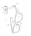
実施例では、加速度センサ及び角速度センサを搭載する対象として、アイウエアを例に挙げる。図1は、実施例における情報処理システム1の一例を示す図である。図1に示す情報処理システム1は、外部装置10とアイウエア30とを含み、外部装置10とアイウエア30は、ネットワークを介して接続され、データ通信可能になっている。
[Example]
In the embodiment, eyewear will be described as an example on which an acceleration sensor and an angular velocity sensor are mounted. FIG. 1 is a diagram illustrating an example of an
アイウエア30は、例えばテンプル部分に処理装置20を搭載する。処理装置20は、3軸加速度センサ及び3軸角速度センサ(6軸センサでもよい)を含む。また、アイウエア30は、一対のノーズパッド及びブリッジ部分にそれぞれ生体電極31、33、35を有してもよい。アイウエア30に生体電極が設けられる場合、これらの生体電極から取得される眼電位信号は、処理装置20に送信される。
The
処理装置20の設置位置は、必ずしもテンプルである必要はないが、アイウエア30が装着された際のバランスを考慮して位置決めされればよい。
The installation position of the
外部装置10は、通信機能を有する情報処理装置である。例えば、外部装置10は、ユーザが所持する携帯電話及びスマートフォン等の携帯通信端末やPC(Personal Computer)等である。外部装置10は、処理装置20から受信したセンサ信号等に基づいて、ユーザの走行又は歩行(以下、走行等やランニングとも称す。)時のフォームの状態を示すオブジェクトを表示する。このとき、理想や目標とするフォームの状態を示すオブジェクトを、現在のフォームを示すオブジェクトに重畳して表示することで、現在の自分のフォームがどのような状態にあるのかを容易に把握することができるようになる。以下、外部装置10は、情報処理装置10と称して説明する。
The
<情報処理装置10のハードウェア構成>
図2は、実施例における情報処理装置10のハードウェア構成を示す概略構成図である。情報処理装置10の典型的な一例は、スマートフォンなどの携帯電話機であるが、この他、ネットワークに無線又は有線接続可能な携帯端末、あるいはタブレット型端末のようなタッチパネルを搭載した電子機器など、ネットワークを使って通信しながらデータ処理しつつ画面表示可能な汎用機器なども実施形態における情報処理装置10に該当しうる。
<Hardware configuration of
FIG. 2 is a schematic configuration diagram illustrating a hardware configuration of the
実施形態における情報処理装置10は、例えば、図示しない矩形の薄形筐体を備え、その筐体の一方の面には、タッチパネル102が構成される。情報処理装置10では、各構成要素が主制御部150に接続されている。主制御部150は、例えばプロセッサである。
The
主制御部150には、移動体通信用アンテナ112、移動体通信部114、無線LAN通信用アンテナ116、無線LAN通信部118、記憶部120、スピーカ104、マイクロフォン106、ハードボタン108、ハードキー110及び6軸センサ111が接続されている。また、主制御部150には、さらに、タッチパネル102、カメラ130、及び外部インターフェース140が接続されている。外部インターフェース140は、音声出力端子142を含む。
The
タッチパネル102は、表示装置及び入力装置の両方の機能を備え、表示機能を担うディスプレイ(表示画面)102Aと、入力機能を担うタッチセンサ102Bとで構成される。ディスプレイ102Aは、例えば、液晶ディスプレイや有機EL(Electro Luminescence)ディスプレイなどの一般的な表示デバイスにより構成される。タッチセンサ102Bは、ディスプレイ102Aの上面に配置された接触操作を検知するための素子及びその上に積層された透明な操作面を備えて構成される。タッチセンサ102Bの接触検知方式としては、静電容量式、抵抗膜式(感圧式)、電磁誘導式など既知の方式のうちの任意の方式を採用することができる。
The
表示装置としてのタッチパネル102は、主制御部150によるプログラム122の実行により生成されるアプリケーションの画像を表示する。入力装置としてのタッチパネル102は、操作面に対して接触する接触物(プレイヤの指やスタイラスなどを含む。以下、「指」である場合を代表例として説明する。)の動作を検知することで、操作入力を受け付け、その接触位置の情報を主制御部150に与える。指の動作は、接触点の位置または領域を示す座標情報として検知され、座標情報は、例えば、タッチパネル102の短辺方向及び長辺方向の二軸上の座標値として表される。
The
情報処理装置10は、移動体通信用アンテナ112や無線LAN通信用アンテナ116を通じてネットワークNに接続され、処理装置20との間でデータ通信をすることが可能である。なお、記憶部120は、プログラム122を記録し、また、記憶部120は、外部装置10と別体であってもよく、例えば、SDカードやCD−RAM等の記録媒体であってもよい。
The
<処理装置20の構成>
図3は、実施例における処理装置20の構成の一例を示すブロック図である。図3に示すように、処理装置20は、処理部202、送信部204、6軸センサ206、及び電源部208を有する。また、各生体電極31、33、35は、例えば増幅部を介して電線を用いて処理部202に接続される。なお、処理装置20の各部は、一方のテンプルに設けられるのではなく、一対のテンプルに分散して設けられてもよい。
<Configuration of the
FIG. 3 is a block diagram illustrating an example of a configuration of the
6軸センサ206は、3軸加速度センサ及び3軸角速度センサである。また、これらの各センサは別個に設けられてもよい。6軸センサ206は、検出したセンサ信号(又は検出データとも称す)を処理部202に出力する。
The six-
処理部202は、例えばプロセッサであり、6軸センサ206から得られるセンサ信号を必要に応じて処理し、送信部204に出力する。例えば、処理部202は、6軸センサ206からのセンサ信号を用いて、ピッチ(Pitch)角を示す第1データ、ロール(Roll)角を示す第2データ、及び体軸の傾きの方向と大きさを含む姿勢を示す第3データを生成する。ピッチ角は、例えば頭の前後のブレを示し、ロール角は、例えば頭の左右のブレを示し、体軸の傾きの方向及び大きさは、例えば頭の傾きの方向及び大きさを示す。ピッチ角、ロール角、及び姿勢については、公知の技術を用いて算出すればよい。また、処理部202は、6軸センサ206から得られるセンサ信号を増幅等するだけでもよい。
The
送信部204は、処理部201によって処理された第1データから第3データを含む各データを情報処理装置10に送信する。例えば、送信部204は、Bluetooth(登録商標)及び無線LAN等の無線通信、又は有線通信によってセンサ信号又は各データを情報処理装置10に送信する。電源部208は、処理部202、送信部204、6軸センサ206等に電力を供給する。
The
<情報処理装置10の構成>
次に、情報処理装置10の構成について説明する。図4は、実施例における情報処理装置10の構成の一例を示す図である。情報処理装置10は、記憶部302、通信部304、及び制御部306を有する。
<Configuration of
Next, the configuration of the
記憶部302は、例えば、図2に示す記憶部120等により実現されうる。記憶部302は、実施例におけるランニングのアプリケーションに関するデータ、例えば、処理装置20から受信したデータや、画面に表示される画面情報等を記憶する。
The
通信部304は、例えば移動体通信部114や無線LAN通信部118等により実現されうる。通信部304は、例えば処理装置20からデータを受信する。また、通信部304は、情報処理装置10において処理されたデータをサーバ(不図示)に送信したりしてもよい。すなわち、通信部304は、送信部と受信部としての機能を有する。
The
制御部306は、例えば主制御部150等により実現されうる。制御部306は、ランニングのアプリケーションを実行する。実施例におけるランニングのアプリケーションは、通常のランニングのアプリケーションの機能に加え、ランナーのフォームの状態を容易に把握することができるような機能を有する。この機能を実現するため、制御部306は、取得部312、設定部314、実行処理部316、後処理部318、及び表示制御部320を有する。
The
取得部312は、人体に装着された6軸センサ206からの検出データに基づく人体の前後のブレを示す第1データ、人体の左右のブレを示す第2データ、及び人体の体軸の傾きの方向と大きさを含む姿勢を示す第3データのうち少なくとも1つを取得する。人体に装着されたとは、直接的に装着されることだけではなく、アイウエア30等を含むウェアラブルデバイスを用いて間接的に装着されることを含む。
The
表示制御部320は、記憶部302に記憶された前後のブレ、左右のブレ、及び姿勢の各閾値のうち、取得された第1データ、第2データ及び/又は第3データに対応する閾値に基づき形成される基準オブジェクトを、画面内の所定座標上に表示制御する。各閾値は、予め記憶部302に記憶されていてもよいし、所定時間計測された第1データ、第2データ、及び/又は第3データから求められて記憶されてもよい。
The
表示制御部320は、取得部312により取得された第1データ、第2データ、及び/又は第3データに基づき形成される対象オブジェクトを、基準オブジェクトと同じ所定座標上に表示制御する。これにより、自身のフォームに対する理想や目標となる基準オブジェクトに対して、自身のランニング時に計測されたデータに基づく対象オブジェクトを重畳することができ、自身のフォームに対する客観的指標を容易にユーザに把握させることができる。また、基準オブジェクトに重畳されて自身のフォームの状態を示す対象オブジェクトが形成され、表示されるので、自身のフォームの状態の視認性を向上させることができる。なお、以下に示す例では、取得部312により第1データ、第2データ、及び第3データが取得されたとする。
The
また、表示制御部320は、画面内に表示された対象オブジェクトのうち、基準オブジェクトの外又は内の領域を識別可能にしてもよい。例えば、表示制御部320は、基準オブジェクトからはみ出た対象オブジェクトの部分を、もともとの色から他の色に変更したり、パターンを変更したりしてもよい。これにより、ユーザは、対象オブジェクトの閾値からはみ出た部分を容易に判別することができ、自身のフォームの悪いところを容易に把握することができ、さらには自分のフォームに反映させることも可能になる。
In addition, the
設定部314は、前後のブレ、左右のブレ、及び姿勢の各項目の閾値を設定する。例えば、設定部314は、ユーザにより設定された各項目に対応する閾値を、都度取得される各データの比較対象に設定する。より具体的には、設定部314は、ユーザの目標や走る場所に対応する閾値のセットを複数用意しておき、設定された目標や場所に応じてそれぞれの閾値を、都度取得される各データの比較対象に設定する。これにより、閾値の設定を可変にすることができ、ランナーのレベルや環境に合わせて、より適切な閾値を用いることができる。なお、設定部314の詳細は、図5を用いて後述する。
The
実行処理部316は、走行等の時に得られるデータを処理する機能を主に有する。実行処理部316は、例えば、走行等の時に得られるデータから、フォームの状態を示す対象オブジェクトを形成したり、怪我の可能性等を判定したり、安定した走行等ができなくなったとみなす時点を判定したりする。実行処理部316の詳細は図6を用いて後述する。
The
後処理部318は、走行等の結果等を処理する機能を主に有する。ここでいう結果とは、例えば、走行等のペースや走行等の距離、走行等の軌跡、時系列における走行等時のフォームの状態を集計した結果を示す。後処理部318は、図7を用いて後述する。
The
表示制御部320は、タッチパネル102に表示される画面の表示を制御する。例えば、表示制御部320は、上述したように、ランニングのアプリケーションにおける画面情報を生成したり、この画面情報に基づく画面が表示されるように制御したりする。
The
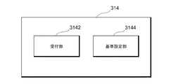
≪設定部≫
図5は、実施例における設定部314の構成の一例を示す図である。図5に示す設定部314は、受付部3142及び基準設定部3144を有する。
≪Setting section≫
FIG. 5 is a diagram illustrating an example of a configuration of the
受付部3142は、記憶部302に記憶された各閾値を含む複数のセットの中から、一のセットの選択を受け付ける。例えば、受付部3142は、ランニングのアプリケーションの設定画面において、目標とするペースや、走行等の場所(屋内又は屋外)などをユーザに選択させ、この選択結果を受け付ける。
The receiving
基準設定部3144は、受け付けられたペースや走行等の場所に対応する一のセットを取得し、取得された一のセット内の各閾値に基づいて、基準オブジェクトのパラメータを設定する。例えば、基準設定部3144は、頭の前後のブレ、左右のブレ、姿勢の各閾値を、基準オブジェクトの縦幅、横幅、及び中心の範囲に重複しないように1対1に対応付けて設定する。これにより、ユーザにより設定された項目に応じて、適切な閾値を設定しておくことができる。
The
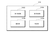
≪実行処理部≫
図6は、実施例における実行処理部316の構成の一例を示す図である。実行処理部316は、第1形成部3162、第2形成部3164、識別部3166、及び判定部3168を有する。
≪Execution processing unit≫
FIG. 6 is a diagram illustrating an example of a configuration of the
第1形成部3162は、設定部314により設定された各閾値に基づく基準オブジェクトを形成する。例えば、頭の前後のブレ、左右のブレ、姿勢の各閾値は、基準オブジェクトの縦幅、横幅、及び中心の範囲に重複しないように1対1に対応付けて設定されている。これにより、ユーザの走行等の基準となるオブジェクトを、シンプルな形状を用いて形成しておくことができる。具体例として、頭の前後のブレの閾値は、直感的に対応する縦幅、左右のブレの閾値は、直感的に対応する横幅、姿勢の閾値は、直感的に対応する中心の幅に設定されるとよい。なお、閾値は範囲を有するものでもよい。
The first forming
第2形成部3164は、取得部312により取得された第1データ、第2データ、及び第3データそれぞれを、対象オブジェクトの縦幅、横幅、及び中心の範囲に対し、基準オブジェクトの対応関係に基づいて設定し、対象オブジェクトを形成する。形成された基準オブジェクトや対象オブジェクトは、画面内の同じ座標系を用いて表示される。これにより、オブジェクトのサイズや形状により、自身のフォームの状態をユーザに容易に把握させ、また、安定した走行等を判定するための閾値と容易に比較を行うことができる。
The second forming
また、取得部312は、加速度センサの鉛直方向の加速度データに基づく、左右の足の接地時のインパクト比を示す第4データをさらに取得してもよい。
Further, the
このとき、表示制御部320は、鉛直方向の加速度データ及びロール角を表す第2データに基づいて、左右の足のどちらが接地しているかを報知する画面を表示制御してもよい。例えば、表示制御部320は、左右の足を表す一対のオブジェクトを用いて、左右の足のどちらが接地しているかを報知するよう制御する。なお、制御部306が、鉛直方向の加速度データにより地面の接地を認識し、ロール角にて横方向の振れ幅を認識する。ロール角の知見として、右足の着地時には右に振れ、左足の着地時には左に振れることが分かっている。
At this time, the
そこで、制御部306は、ロール角において右に振れることが認識できれば右足を接地したと判定し、左に振れることが認識できれば左足を接地したと判定する。これにより、足が地面に接地する場合の衝撃を認識し、ロール角でどちらの方向に傾いているかを判定すれば、いずれの足が地面に接地しているかを判定することができる。なお、ランニング中は交互に足を接地することが考えられるため、いずれの足が接地したかの判定は、間隔を空けて定期的に行われるようにしてもよい。これにより、省電力化を図ることができる。
Therefore, the
識別部3166は、左右の足の接地時のインパクト比を示す第4データが怪我に関する所定条件を満たす場合、左右の足を表す一対のオブジェクトに対し、怪我の可能性がある方のオブジェクトを識別可能にする。オブジェクトは、例えば足跡や足裏の形状である。識別部3166は、怪我の可能性について、左右の足それぞれの鉛直方向の加速度データの比が、所定の範囲内であれば、怪我の可能性がないと判定する。例えば、識別部3166は、右の足の鉛直方向の加速度データの値/左の足の鉛直方向の加速度データの値が、0.95以上1.05以下であれば、怪我の可能性がないと判定し、0.95未満であれば、右足に怪我の可能性ありと判定し、1.05超であれば、左足に怪我の可能性ありと判定する。これは、怪我の可能性が有る足を庇って、怪我の可能性が有る足の接地時間が短くなるという知見に基づく。
When the fourth data indicating the impact ratio of the left and right feet at the time of touching the ground satisfies the predetermined condition regarding the injury, the
識別部3166は、怪我の可能性ありと判定された方のオブジェクトについて、色やパターンなどを変更して強調することで、怪我の可能性があることをユーザに知らせる。すなわち、ユーザは、無意識のうちに、どちらの足を庇っているかなどを知ることができる。
The
また、取得部312は、加速度センサの鉛直方向の加速度データに基づく、左右の足の接地時のインパクト比を示す第4データ、及び/又はGPS(Global Positioning System)センサ又は加速度センサからの検出データに基づく、所定距離を移動するペースを示す第5データをさらに取得してもよい。
Further, the
このとき、判定部3168は、例えば第1データから第5データまでの各データのうち少なくとも1つに基づいて、フォームの安定性に関する問題が発生した時点(以下、ブレイクポイントともいう。)を判定する。ブレイクポイントとは、安定したフォームで走行等することができなくなったとみなされる時点をいう。
At this time, the
例えば、判定部3168は、第1データから第5データまでの各データについて、各データに対する閾値を超えたか否かを判定する。閾値を超えるデータがある場合は、判定部3168は、ブレイクポイントが発生したと判定してもよい。また、判定部3168は、第1データから第5データに関する条件に対し、条件が満たされた時にブレイクポイントの発生を判定してもよい。実施例におけるブレイクポイント発生条件については、図9や図10を用いて後述する。
For example, the
ブレイクポイントが発生した場合、表示制御部320は、ブレイクポイントを示す情報を画面に表示するように制御する。なお、ブレイクポイントを示す情報は、画面に表示するだけではなく、音声等で報知されるようにしてもよい。これにより、ユーザは走行等の途中にブレイクポイントを把握することができ、どの時点で自分のフォームが崩れたのかを把握することができる。また、判定部3168は、ブレイクポイントが発生した場合、ブレイクポイントの地点、走行距離、走行時間、各データの値などを記憶部302に記憶するようにする。これにより、ユーザは、走行等の後に、ブレイクポイントの発生等について分析することができる。
When a breakpoint occurs, the
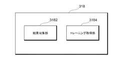
≪後処理部≫
図7は、実施例における後処理部318の構成の一例を示す図である。図7に示す例では、後処理部318は、結果収集部3182及びトレーニング取得部3184を有する。
≪Post-processing unit≫
FIG. 7 is a diagram illustrating an example of a configuration of the
結果収集部3182は、走行等の結果データを収集する。結果収集部3182は、走行等の結果データに基づいて、走行等の評価を行う。評価結果は、画面に表示されたり、音声等でユーザに報知されたりする。
The
結果収集部3182は、結果画面においても、安定した走行等ができなくなったとみなされる時点(ブレイクポイント)を示す情報をユーザに知らせるようにする。ブレイクポイントを示す情報は、このブレイクポイントの発生に起因した主要なデータに関する情報を含む。これにより、主に何が原因でブレイクポイントが発生したのかをユーザに知らせることができる。
The
トレーニング取得部3184は、主要なデータに対応するトレーニング部位を、例えば記憶部302から取得する。第1データから第5データの各データに対して、トレーニング部位が1又は複数対応付けられていればよい。取得されたトレーニング部位に関する情報は、画面内に表示されるよう制御される。また、トレーニング部位は、音声等で報知されてもよい。これにより、ユーザは、実際に運動したことによって発見された自分の弱みに対するトレーニング部位を知ることができる。
The
<データ例>
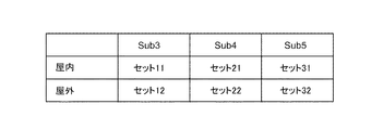
次に、実施例におけるランニングのアプリケーションに用いられる各種データの例について説明する。図8は、閾値のセット例を示す図である。図8に示す例では、例えば、横軸にフルマラソンの目標タイムが設定され、縦軸に走る場所が設定される。
<Example of data>
Next, examples of various data used for a running application in the embodiment will be described. FIG. 8 is a diagram illustrating a set example of threshold values. In the example shown in FIG. 8, for example, the target time of the full marathon is set on the horizontal axis, and the location of the run is set on the vertical axis.
横軸として、「Sub3」、「Sub4」、「Sub5」が設定され、それぞれ、フルマラソンに対して3時間以内、4時間以内、5時間以内を表す。縦軸として、「屋内」又は「屋外」は、走る場所を表す。 As the horizontal axis, “Sub3”, “Sub4”, and “Sub5” are set, and represent within 3 hours, within 4 hours, and within 5 hours of the full marathon, respectively. As the vertical axis, “indoor” or “outdoor” represents a running place.
このとき、閾値のセットは、頭の前後のブレ、頭の左右のブレ、姿勢(頭の傾きの方向及び大きさ)それぞれに対する閾値を含むとする。それぞれの閾値は、事前に各項目に対応するランナーにアイウエア30を装着して走ってもらい、その時に取得されたデータに基づいて設定される。
At this time, it is assumed that the set of thresholds includes thresholds for the front and rear blur of the head, the right and left blur of the head, and the posture (the direction and size of the head tilt). Each threshold value is set based on data acquired at that time by having the runner corresponding to each item run with the
設定部314は、ランニングのアプリケーションの設定画面において、横軸の項目及び縦軸の項目を設定できるようにしておくとよい。なお、横軸については、フルマラソンの目標を設定しない項目(例えば「Free」)等を有してもよい。このとき、ランニング初期の所定時間や所定歩数で取得された各データに基づいて、閾値が設定されればよい。例えば、制御部306は、ランニング初期の所定時間や所定歩数で取得された各データ(特に第1データ、第2データ、及び第3データ)の平均を、閾値として設定する。
It is preferable that the
図8に示す例において、走る場所を屋内又は屋外で分けた理由は、屋内はトレッドミルを使って走る場合がほとんどであり、トレッドミルでは走る空間が限られているため、屋外を走るよりもフォームのブレが小さいことが分かっているからである。したがって、この違いを反映させるために、屋内か屋外かをユーザに選択させ、選択された項目に従って、適切な閾値が設定されるようにする。 In the example shown in FIG. 8, the reason why the running place is divided indoors or outdoors is that most of the indoors run using a treadmill, and since the running space is limited in the treadmill, it is better than running outdoors. This is because it is known that the shake of the form is small. Therefore, in order to reflect this difference, the user is made to select between indoor and outdoor, and an appropriate threshold is set according to the selected item.
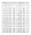
図9は、モードAの場合に記録された各データの一例を示す図である。図9に示すモードAは、例えば、予め設定されている閾値を用いない項目「Free」のモードであり、図9は、このときに記録されたデータ例を示す。図9に示す例では、判定区間ごとに、Pitch、Roll、左右バランス、ペース、姿勢、及び総合点が対応付けられる。 FIG. 9 is a diagram illustrating an example of each data recorded in the case of the mode A. Mode A shown in FIG. 9 is, for example, a mode of the item “Free” that does not use a preset threshold, and FIG. 9 shows an example of data recorded at this time. In the example illustrated in FIG. 9, Pitch, Roll, left / right balance, pace, posture, and total score are associated with each determination section.
図9に示す判定区間は、20歩で1つの判定区間を表す。Pitchは、ランニング中のフォームの前後のブレの振れ幅を表す。Rollは、ランニング中のフォームのブレの振れ幅を表す。左右バランスは、左右それぞれの足の接地時のインパクト(衝撃)の大きさの比を表す。ペースは、1キロにおける走行時間を表す。姿勢は、体軸の傾きの方向と大きさとを表す。 The determination section shown in FIG. 9 represents one determination section with 20 steps. “Pitch” indicates the swing width of the shake before and after the running form. Roll represents the swing width of the foam during running. The left-right balance indicates the ratio of the magnitude of the impact (shock) when the right and left feet touch the ground. The pace represents the running time in one kilometer. The posture indicates the direction and magnitude of the inclination of the body axis.
図9に示すデータを用いて、判定部3168は、ブレイクポイントを判定する。まず、基本処理として、処理部202又は制御部306により、以下の処理がなされる。
・毎歩ごとにPitch、Roll、及び左右バランスの値を算出
・20歩分の値で、Pitch、Roll、及び左右バランスの平均値を算出し、また、20歩の距離と時間でペースタイムを算出
・20歩分の平均値を1判定区間とする
・姿勢のみ10判定区間(200歩)で算出
なお、1歩分が1秒以内に検出されないと、走行等していないと判定される。実行処理部316は、以下の流れで処理を行う。
Using the data shown in FIG. 9, the
・ Pitch, Roll and left / right balance values are calculated for each step. ・ Pitch, Roll and left / right balance values are averaged for 20 steps, and the pace time is calculated based on distance and time for 20 steps. Calculation: The average value of 20 steps is set as one determination section. Only the posture is calculated in 10 determination sections (200 steps). If one step is not detected within one second, it is determined that the vehicle is not running. The
(1)スタートから40判定区間(約1km)まで
スタートから800歩(40判定区間≒1km)は基準値作成区間のため、閾値判定はしない。基準値とは、ユーザの初期段階での走行等により求められる値であり、最初に形成される対象オブジェクトの基になる値である。また、実行処理部316は、作成された基準値に対して設定された閾値と、以降の判定区間での値とを比較する。なお、800歩が1kmに満たない場合、最初のフィードバックは1km到達時とする。なお、「Free」のモードの場合、閾値は、基準値に基づいて設定される。例えば、基準値が閾値として設定されてもよいし、基準値から所定の基準を用いて変更された値が閾値として設定されてもよい。
(1) From start to 40 judgment section (about 1 km) 800 steps (40 judgment section ≒ 1 km) from the start are threshold value judgment sections, so threshold judgment is not performed. The reference value is a value obtained by the user traveling at an initial stage or the like, and is a value that is a base of the initially formed target object. Further, the
(2)41判定区間以降
判定部3168は、判定区間ごとに算出された4項目(Pitch、Roll、左右バランス、及びペース)が閾値を越えていれば、項目ごとに加点する。
・Pitch:1点
・Roll:1点
・左右バランス:0.5点
・ペース1.5点
なお、姿勢は、計算周期が異なる。例えば、判定部3168は、10判定区間ごとに1回姿勢を判定し、閾値を超えていれば加点する。
・姿勢:0.5点
(2) After 41 judgment sections If the four items (Pitch, Roll, left / right balance, and pace) calculated for each judgment section exceed the threshold value, the
-Pitch: 1 point-Roll: 1 point-Left / right balance: 0.5 point-1.5 points of pace Note that the posture has a different calculation cycle. For example, the
-Posture: 0.5 points
総合点は、対応する行の合計点を表す。判定部3168は、総合点が3区間連続して2.5点以上の場合、3区間目をブレイクポイントとして判定し、記録する。図9に示す場合、判定部3168は、53区間を、ブレイクポイントとして判定する。このとき、ブレイクポイントに対応付けて時間や、走行距離や、各種データが記憶部302に記録されてもよい。
The total score represents the total score of the corresponding row. When the total score is 2.5 points or more for three consecutive sections, the
なお、実行処理部316は、約1km(40区間の倍数)ごとに、ペースとフォームとをユーザにフィードバックしてもよい。ペースは、例えば音声でフィードバックされ、フォームは、例えばフォームの状態を示すオブジェクトを表示することでフィードバックされる。
Note that the
図10は、モードBの場合に記録された各データの一例を示す図である。図10に示すモードBは、例えば、予め設定されている閾値を用いるモードであり、図10は、このときに記録されたデータ例を示す。図10に示す例では、判定区間ごとに、Pitch、Roll、左右バランス、ペース、姿勢、総合点、及びクラスが対応付けられる。基本処理は、図9で説明した基本処理と同じである。実行処理部316は、以下の流れで処理を行う。
FIG. 10 is a diagram showing an example of each data recorded in the case of mode B. Mode B shown in FIG. 10 is, for example, a mode using a preset threshold value, and FIG. 10 shows an example of data recorded at this time. In the example illustrated in FIG. 10, Pitch, Roll, left / right balance, pace, posture, total score, and class are associated with each determination section. The basic processing is the same as the basic processing described in FIG. The
(1)サブクラス判定
判定部3168は、判定区間ごとに算出された4項目(Pitch、Roll、左右バランス、及びペース)がa〜dのどのサブクラスに該当するか判定する。例えば、判定部3168は、それぞれの因子ごとに定められた閾値に応じて、サブクラスa〜dを決定する。
(1) Subclass determination The
(2)加点
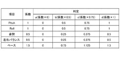
判定部3168は、判定されたa〜dのサブクラスに応じ、加点する。図11は、サブクラスと点数との関係を示す図である。図11に示す例では、判定部3168は、Pitchのサブクラスがbの場合、0.5点を加点する。なお、姿勢は、計算周期が異なる。判定部3168は、10判定区間ごとに1回姿勢を判定し、(1)と同様にa〜dを判定し、加点する。
(2) Point addition The
(3)総合点の算出
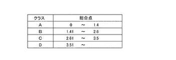
判定部3168は、判定区間ごとに総合点を算出し、クラスA〜Dの総合判定を行う。図12は、総合点とクラスとの関係を示す図である。図12に示す例では、判定部3168は、総合点が1.75の場合、クラスBと判定し、加点する。
(3) Calculation of Total Point The
(4)ブレイクポイントの判定
判定部3168は、総合判定結果(クラス)がA→B、A→C、A→D、B→C、B→D、又はC→Dとダウンし、その状態からアップせずにダウンもしくは維持が3判定区間連続した場合、3区間目をブレイクポイントとして判定し、記録する。このとき、ブレイクポイントに対応付けて時間や、走行距離や、各種データが記憶部302に記録されてもよい。なお、図9又は図10に示すテーブルの各項目を縦方向の時間軸で見ていくと、その項目における異常の発生を検知することができる。
(4) Breakpoint determination The
次に、ランニングの終了後に、画面に表示されるトレーニング部位の例について説明する。図13は、トレーニング部位の情報の一例を示す図である。図13に示す例では、ブレイクポイントの発生の有無によりトレーニング部位の提示が異なる。主要項目は、各項目の中で高得点の項目を示す。例えば図10に示す例の場合、各項目の平均点が一番高いRollが主要項目とみなされる。なお、主要項目は、平均点が一番高いものだけに限られない。 Next, an example of a training site displayed on the screen after the end of running will be described. FIG. 13 is a diagram illustrating an example of information on a training site. In the example illustrated in FIG. 13, the presentation of the training site differs depending on whether or not a breakpoint has occurred. The main item indicates the item with the highest score among the items. For example, in the case of the example shown in FIG. 10, Roll having the highest average score of each item is regarded as the main item. The main items are not limited to those having the highest average score.
例えば、Rollが主要項目の場合、トレーニング部位は、腹横筋、腹斜筋、及びハムストリングスである。このとき、全ての部位が画面に表示されてもよいし、いずれか1つの部位が所定順又はランダムに選択されて画面に表示されてもよい。トレーニング部位が1つ選択される場合、主要項目が毎回同じになった場合でも、トレーニング部位が毎回同じにならないようにすることができる。 For example, when Roll is the main item, the training sites are the transverse abdominal muscle, the oblique muscle, and the hamstrings. At this time, all the parts may be displayed on the screen, or any one part may be selected on a predetermined order or randomly and displayed on the screen. When one training site is selected, it is possible to prevent the training site from being the same every time, even if the main item becomes the same each time.
なお、コメントについては、ランニング終了後に表示画面内に表示される文章、又は出力される音声の内容である。 Note that the comment is a sentence displayed on the display screen after the end of the running or the content of the output voice.
<画面例>
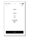
次に、実施例におけるランニングのアプリケーションの画面例について説明する。図14は、設定画面の一例を示す図である。図14に示す画面は、例えばアプリケーションの実行後の初期段階において表示される画面であり、目標(TARGET)と走る場所(LOCATION)とをユーザに選択させる画面である。
<Screen example>
Next, a screen example of a running application in the embodiment will be described. FIG. 14 is a diagram illustrating an example of the setting screen. The screen shown in FIG. 14 is, for example, a screen displayed in an initial stage after the execution of the application, and is a screen for allowing the user to select a target (TARGET) and a running place (LOCATION).
例えば、設定部314は、例えば目標「Sub4」及び場所「屋外」が選択されると、図8に示すセット22を取得し、セット22に含まれる各閾値を、基準オブジェクトのパラメータとして設定する。図14に示す画面において、Startボタンが押されると、ランニングのための諸データの計測及び/又は記録が始まる。
For example, when the target “Sub4” and the place “outdoor” are selected, for example, the
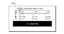
図15は、ランニング中に表示される画面の一例を示す図である。図15に示す例では、走行距離、平均ペース、及び消費カロリーなどの一般的なランニングアプリケーションにおいて表示される項目の他、ブレイクポイントが発生した地点やランニングフォームに関するオブジェクトなどが表示される。 FIG. 15 is a diagram illustrating an example of a screen displayed during running. In the example illustrated in FIG. 15, items displayed in a general running application such as a running distance, an average pace, and calorie consumption, as well as a point where a breakpoint occurs and an object related to a running form are displayed.
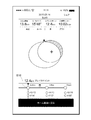
図15に示す例において、表示制御部320は、第1形成部3162により生成された基準オブジェクトS10、及び第2形成部3164により生成された対象オブジェクトT10を同じ座標系を用いて画面に表示するよう制御する。対象オブジェクトT10の中心C10は、第3データを用いて求めることができる。
In the example illustrated in FIG. 15, the
各オブジェクトは、例えば円形状(楕円形状も含む)のオブジェクトで表され、各種オブジェクトの中心は体軸の中心を表し、横幅は、フォームの左右のブレ幅を表し、縦幅は、フォームの前後のブレ幅を表す。 Each object is represented by, for example, a circular (including elliptical) object, the center of each object represents the center of the body axis, the horizontal width represents the width of the left and right sides of the form, and the vertical width represents the front and rear of the form. Represents the blur width.
また、表示制御部320は、対象オブジェクトT10の領域内で、基準オブジェクトS10の外にある領域を、例えば色を変えるなどの強調表示を行うことにより、他の領域に対して識別可能にする。これにより、ユーザは、対象オブジェクトが強調表示されていなければ、目標を達成できる理想のフォームで走行することができていること、又は対象オブジェクトが強調表示されていれば、フォームのどこが悪いことにより、理想のフォームで走行することができていないことを一見して容易に把握することができる。
In addition, the
また、図15に示す画面には、対象オブジェクトT10の中心C10に基づいて、現在のユーザのフォームの姿勢の中心がどのような状態になっているのかを知らせることもできる。例えば、図15に示す場合、体が右前方に傾いていることが画面内に表示される。 The screen shown in FIG. 15 can also inform the user of the current state of the center of the form posture based on the center C10 of the target object T10. For example, in the case shown in FIG. 15, the fact that the body is leaning right forward is displayed on the screen.
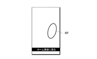
図16は、ランニング中に表示される画面の他の例を示す図である。図16に示す画面は、図15に示す画面と切替可能である。図16Aは、右足のオブジェクトRFが表示される例を示す図である。図16Bは、左足のオブジェクトLFが表示される例を示す図である。図16Bに示す画面は、図16Aに示す画面の次に表示される。 FIG. 16 is a diagram illustrating another example of a screen displayed during running. The screen shown in FIG. 16 can be switched with the screen shown in FIG. FIG. 16A is a diagram illustrating an example in which the right foot object RF is displayed. FIG. 16B is a diagram illustrating an example in which the left foot object LF is displayed. The screen shown in FIG. 16B is displayed next to the screen shown in FIG. 16A.
図16Cは、右足のオブジェクトRFが表示される例を示す図である。図16Cに示す画面は、図16Bに示す画面の次に表示される。図16Dは、左足のオブジェクトLFが表示される例を示す図である。図16Dに示す画面は、図16Cに示す画面の次に表示される。 FIG. 16C is a diagram illustrating an example in which the object RF of the right foot is displayed. The screen shown in FIG. 16C is displayed next to the screen shown in FIG. 16B. FIG. 16D is a diagram illustrating an example in which the left foot object LF is displayed. The screen shown in FIG. 16D is displayed next to the screen shown in FIG. 16C.
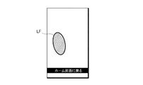
図16Dに示す例では、識別部3166は、左右の足のバランスの悪さを検出し、さらに、左足に怪我の可能性があることを判定したとする。この場合、識別部3166は、表示される左足のオブジェクトLFの色やパターンを変えるなどしてユーザに異常を知らせるようにする。これにより、ユーザ自身が気づいていないような足を庇う行為を迅速に判断し、ユーザに知らせることができるようになる。
In the example illustrated in FIG. 16D, it is assumed that the
図17は、ランニングの結果である表の表示画面の一例を示す図である。図17に示す例では、1kmごとに、平均ペース、前後のブレ、及び左右のブレが表示される。図17に示す例では、7.2kmでブレイクポイントが発生したことを示す。また、図17に示すように、ブレイクポイントが発生した走行距離に関する項目を、識別可能な状態で表示するようにしてもよい。ブレイクポイントについては、記憶部302がブレイクポイントに対する各データを記録しているため、図17に示す表示が可能になる。
FIG. 17 is a diagram illustrating an example of a display screen of a table that is a result of running. In the example shown in FIG. 17, the average pace, the front-back blur, and the left-right blur are displayed every 1 km. The example shown in FIG. 17 indicates that a breakpoint has occurred at 7.2 km. In addition, as shown in FIG. 17, an item related to a travel distance at which a breakpoint has occurred may be displayed in an identifiable state. Regarding the breakpoint, the
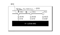
図18は、ランニングの結果であるルートの表示画面の一例を示す図である。図18に示す画面下部を左や右にスライドさせることで、走行距離を変えつつ、そのときの平均ペースやフォームに対するオブジェクトの形状等を確認することができる。また、表示制御部320は、図18に示すように、ブレイクポイントの地点が分かるマークB10を表示するようにしてもよい。
FIG. 18 is a diagram illustrating an example of a display screen of a route that is a result of running. By sliding the lower part of the screen shown in FIG. 18 left or right, it is possible to check the average pace at that time, the shape of the object with respect to the form, and the like while changing the traveling distance. Alternatively, the
図19は、ルートの表示画面における下部の拡大図の一例を示す図である。図19に示す例では、マップボタンM10が表示される。このマップボタンM10が押されると、GPS機能を用いて取得されたランニングルートが表示される(図21参照)。 FIG. 19 is a diagram illustrating an example of an enlarged view of a lower portion of the route display screen. In the example shown in FIG. 19, a map button M10 is displayed. When the map button M10 is pressed, the running route obtained using the GPS function is displayed (see FIG. 21).
図20は、ルートの表示画面における下部の拡大図の他の例を示す図である。図20に示す例では、ブレイクポイントを示すマークB10や、ブレイクポイントを消去するためのボタンD10が表示される。制御部306は、ボタンD10が押されたことを検知すると、記憶部302に記憶されたこの地点におけるブレイクポイントに関するデータを削除する。
FIG. 20 is a diagram illustrating another example of an enlarged view of the lower portion of the route display screen. In the example shown in FIG. 20, a mark B10 indicating a breakpoint and a button D10 for deleting a breakpoint are displayed. When detecting that the button D10 is pressed, the
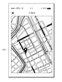
図21は、ランニングの結果であるマップの表示画面の一例を示す図である。図21に示す例では、GPS機能やGPSセンサを用いて取得されたルートが、マップ上にランニングルートとして表示され、さらに、ブレイクポイントが発生した地点にピンB12が表示される。これにより、どの地点でブレイクポイントが発生したかが一目でわかるようになっている。 FIG. 21 is a diagram illustrating an example of a display screen of a map that is a result of running. In the example illustrated in FIG. 21, a route acquired using the GPS function or the GPS sensor is displayed as a running route on a map, and a pin B12 is displayed at a point where a breakpoint has occurred. This makes it possible to see at a glance where the breakpoint occurred.
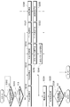
図22は、ランニングの結果であるグラフの表示画面の一例を示す図である。図22に示す例では、前後ブレ、左右ブレ、左右バランス、及び走行ペースのそれぞれが、横軸を時間にした折れ線グラフにより表現されている。図22に示す例においても、ブレイクポイントを示すマークB10が表示される。これにより、各種データの値がどのようなときにブレイクポイントが発生したかが一目でわかるようになっている。 FIG. 22 is a diagram illustrating an example of a display screen of a graph that is a result of running. In the example illustrated in FIG. 22, each of the front-back blur, the left-right blur, the left-right balance, and the running pace is represented by a line graph with the horizontal axis representing time. In the example shown in FIG. 22, a mark B10 indicating a break point is also displayed. This makes it possible to see at a glance when the breakpoints occur in the values of various data.
図23は、トレーニング部位を示す表示画面の一例を示す図である。図23に示す例では、ブレイクポイントの発生あり、主要項目として、姿勢(前)及びペースというランニング結果であったとする。このとき、トレーニング取得部3184は、姿勢(前)に対応する広背筋を取得し、さらに、ペースに対応する腹直筋を取得する。そして、画面に表示された人体オブジェクトの該当箇所に、取得された腹直筋及び広背筋が表示されるようにする。これは、人体オブジェクトの各部位に、各筋肉を示す情報を対応付けられていればよい。これにより、ユーザは、どの部位をトレーニングすればよいかを容易に把握することができるようになる。さらに、ユーザは、その部位を鍛えることにより、どのようなフォームで走ることができるかを認識することができ、積極的にトレーニングを促すことができる。
FIG. 23 is a diagram illustrating an example of a display screen showing a training site. In the example illustrated in FIG. 23, it is assumed that a breakpoint has occurred and the main items are running results of posture (front) and pace. At this time, the
<動作>
次に、実施例における情報処理装置10の動作について説明する。図24は、実施例におけるアプリケーションの全体処理の一例を示すフローチャートである。図24に示すフローチャートは、ユーザがアイウエア30を装着して、情報処理装置10を操作し、上述したアプリケーションを起動するときに行われる処理である。なお、処理装置20と情報処理装置10との接続については、事前に行われていればよい。
<Operation>
Next, an operation of the
図24に示すステップS102で、制御部306は、ユーザ操作に基づき、起動指示があるか否かを判定する。例えば、このアプリケーションのアイコンがタッチされたときに、起動指示ありと判定される。起動指示が有る場合(ステップS102−YES)、処理はステップS104に進み、起動指示がない場合(ステップS102−NO)、処理はステップS102に戻る。
In step S102 illustrated in FIG. 24, the
ステップS104で、設定部314は、設定画面を表示するよう表示制御部320に指示を出し、表示制御部320は、設定画面を表示するよう制御する(図14参照)。
In step S104, the
ステップS106で、設定部314は、ターゲット(目標)の設定を受け付ける。例えば、設定部314は、図14において説明した設定画面に対するユーザ操作に基づいて、FreeやSub4などの項目の設定を受け付ける。
In step S106, the
ステップS108で、設定部314は、ロケーション(走行等の場所)の設定を受け付ける。例えば、設定部314は、図14において説明した設定画面に対するユーザ操作に基づいて、屋内又は屋外の項目の設定を受け付ける。
In step S108, the
ステップS110で、設定部314は、受け付けたターゲット及びロケーションに基づいて、基準オブジェクトを形成するための各閾値を設定する。設定部314は、例えば、図8において説明したテーブルを用いて各閾値のセットを取得し、取得した各閾値を設定する。
In step S110, the
ステップS112で、制御部306は、走行等(以下、移動とも称する)が開始されたか否かを判定する。移動開始は、例えば、図14に示す画面に表示された「Start」ボタンが押されたか否かにより判定される。この「Start」ボタンが押されると、カウントダウンが始まり、カウントが0になると移動開始とする。移動が開始された場合(ステップS112−YES)、処理はステップS114に進み、移動が開始されていない場合(ステップS112−NO)、処理はステップS112に戻る。
In step S112,
ステップS114で、実行処理部316は、移動中における各種データの取得、集計、処理等を行い、実行画面を適時表示するよう表示制御部320に指示する。表示制御部320は、指示された実行画面を表示するよう制御する(図15又は図16A〜D参照)。アプリケーション実行中の表示制御処理については、図25及び図26を用いて後述する。
In step S114, the
ステップS116で、制御部306は、移動が終了したか否かを判定する。移動の終了は、例えば、図15において表示される「スライドして一時停止」が実行された後に、移動の終了がユーザ操作により実行されたか否かにより判定される。移動が終了された場合(ステップS116−YES)、処理はステップS118に進み、移動が終了していない場合(ステップS116−NO)、処理はステップS114に戻る。
In step S116,
ステップS118で、後処理部318は、移動後の各種データの集計、処理等を行い、結果画面を適時表示するよう表示制御部320に指示する。表示制御部320は、指示された実行画面を表示するよう制御する(図17〜23参照)。この後、アプリケーションの起動停止の指示により処理は終了する。
In step S118, the
図25は、実施例における実行画面の表示制御処理の一例を示すフローチャートである。図25に示すステップS202で、第1形成部3162は、設定部314により設定された閾値に基づいて、基準オブジェクトを形成する。例えば、基準オブジェクトは、図15に示すオブジェクトS10により表現されるが、この形状に限られない。
FIG. 25 is a flowchart illustrating an example of an execution screen display control process according to the embodiment. In step S202 illustrated in FIG. 25, the first forming
ステップS204で、表示制御部320は、第1形成部3162により形成された基準オブジェクトを所定の座標系を用いて画面に表示する。
In step S204, the
ステップS206で、取得部312は、6軸センサ206により計測された検出データに基づく、第1データ、第2データ及び第3データを少なくとも取得したか否かを判定する。この場合、取得部312は、所定歩数又は所定期間分の各種データを取得してもよい。データが取得された場合(ステップS206−YES)、処理はステップS208に進み、データが取得されていない場合(ステップS206−NO)、処理はステップS206に戻る。
In step S206, the acquiring
ステップS208で、第2形成部3164は、取得されたデータに基づいて、対象オブジェクトを形成する。例えば、対象オブジェクトは、図15に示すオブジェクトT10により表現されるが、この形状に限られない。この処理後、ステップS210以降の処理と、ステップS216以降の処理とが別々に実行される。
In step S208, the second forming
ステップS210で、識別部3166は、取得された各データ値のうち少なくとも1つが閾値以上であるか否かを判定する。例えば、識別部3166は、対象オブジェクトが基準オブジェクトの領域外にはみ出ているか否かを判定する。各データのうち少なくとも1つが閾値以上である場合(ステップS210−YES)、処理はステップS212に進み、各データ全てが閾値未満である場合(ステップS210−NO)、処理はステップS214に進む。
In step S210, the
ステップS212で、表示制御部320は、対象オブジェクトのうち、基準オブジェクトよりも外側の領域を識別可能にして実行画面Aを表示するよう制御する。例えば、実行画面Aは、図15に示す画面である。
In step S212, the
ステップS214で、表示制御部320は、基準オブジェクト内に対象オブジェクトが表示される実行画面Bを表示するよう制御する。
In step S214, the
ステップS216で、判定部3168は、ブレイクポイントが発生したか否かを判定する。例えば、判定部3168は、ブレイクポイントの発生について、図9や図10に示すデータを用いた処理でブレイクポイントの発生を判定する。ブレイクポイントが発生した場合(ステップS216−YES)、処理はステップS218に進み、ブレイクポイントが発生していない場合(ステップS216−NO)、処理はステップS116に進む。なお、ブレイクポイントの判定処理の詳細は、図26を用いて説明する。
In step S216, the
ステップS218で、表示制御部320は、ブレイクポイントが発生した旨を画面に表示するよう制御する。また、ブレイクポイントが発生したことは、画面表示の代わりに、音声で出力したりしてユーザに知らせてもよい。これにより、ユーザは、移動中に、自分のフォームの現在の状態を容易に知ることができる。
In step S218, the
図26は、実施例におけるブレイクポイントの判定処理の一例を示すフローチャートである。図26に示すステップS302で、判定部3168は、所定歩から構成される判定区間を検出したか否かを判定する。所定歩は、例えば20歩である。所定歩の判定区間が検出された場合(ステップS302−YES)、処理はステップS304に進み、所定歩の判定区間が検出されない場合(ステップS302−NO)、処理はステップS302に戻る。
FIG. 26 is a flowchart illustrating an example of a breakpoint determination process according to the embodiment. In step S302 illustrated in FIG. 26, the
ステップS304で、判定部3168は、所定数の判定区間が経過したか否かを判定する。所定数は、例えば10である。所定数の判定区間が経過した場合(ステップS304−YES)、処理はステップS306に進み、所定数の判定区間が経過していなければ(ステップS304−NO)、処理はステップS310、S312、S314、S320に進む。
In step S304, the
ステップS306で、判定部3168は、所定数の判定区間における姿勢を取得し、その平均を算出する。例えば、取得部312は、10判定区間における体軸の傾きの方向及び大きさの平均(姿勢)を算出する。
In step S306, the
ステップS308で、判定部3168は、10判定区間における姿勢の平均に対応する姿勢点を算出する。姿勢点は、例えば図11に示すテーブルを用いて算出される。なお、算出後に判定区間のカウントがクリアされる結果、ステップS306及びS308は、10判定区間が経過する度に算出される。
In step S308, the
ステップS310で、判定部3168は、1判定区間内に取得されたPitchの平均に対応するPitch点を算出する。Pitch点は、例えば図11に示すテーブルを用いて算出される。
In step S310, the
ステップS312で、判定部3168は、1判定区間内に取得されたRollの平均に対応するRoll点を算出する。Roll点は、例えば図11に示すテーブルを用いて算出される。
In step S312, the
ステップS314で、判定部3168は、着地した足が、左右どちらの足であるかを判定する。判定部3168は、上述したように、加速度データの鉛直方向の値により接地したことが分かり、Roll角において、どちらの足が接地したかを判定することができる。
In step S314, the
ステップS316で、判定部3168は、1判定区間内の平均である左右のバランス値を算出する。左右のバランス値は、例えば右足のインパクト値(鉛直方向の加速度データ値)/左足のインパクト値の1判定区間内の平均を左右のバランス値とする。
In step S316, the
ステップS318で、判定部3168は、左右のバランス値に対応する左右バランス点を算出する。左右バランス点は、例えば図11に示すテーブルを用いて算出される。
In step S318,
ステップS320で、判定部3168は、ペースを算出する。ペースの算出については公知の方法を用いればよい。
In step S320,
ステップS322で、判定部3168は、1判定区間内のペースの平均に対応するペース点を算出する。ペース点は、例えば図11に示すテーブルを用いて算出される。
In step S322,
ステップS324で、判定部3168は、算出された各項目の点を記憶部302に記憶する。
In step S324, the
ステップS326で、判定部3168は、各項目の点を合計し、総合点を算出する。
In step S326,
ステップS328で、判定部3168は、所定回連続して総合点が閾値以上であるか否かを判定する。所定回は、例えば3回である。所定回連続して総合点が閾値以上である場合(ステップS328−YES)、処理はステップS218へ進み、所定回連続して総合点が閾値以上とはならない場合(ステップS328−NO)、処理はステップS116へ進む。
In step S328,
なお、図24〜26で説明した処理のフローに含まれる各処理ステップは、処理内容に矛盾を生じない範囲で、任意に順番を変更して又は並列に実行することができるとともに、各処理ステップ間に他のステップを追加してもよい。また、便宜上1ステップとして記載されているステップは、複数ステップに分けて実行することができる一方、便宜上複数ステップに分けて記載されているものは、1ステップとして把握することができる。 Each processing step included in the processing flow described with reference to FIGS. 24 to 26 can be arbitrarily changed in order or performed in parallel within a range that does not cause inconsistency in the processing content. Other steps may be added in between. Also, steps described as one step for convenience can be executed in a plurality of steps, while those described in a plurality of steps for convenience can be understood as one step.
以上、実施例によれば、走行又は歩行時のフォームの状態をユーザに容易に把握させることができる。また、実施例によれば、フォーム判定の基準となる閾値を、屋内と屋外とで別々に設けることで、より適切な閾値を設定することが可能になる。また、実施例によれば、左右のバランス値に基づき、怪我の可能性がある足を迅速に判断し、ユーザに報知することができる。また、実施例によれば、安定した走行等ができなくなった時点(ブレイクポイント)を判定することにより、どの時点でフォームが崩れたのかを容易に把握することができる。また、実施例によれば、ブレイクポイントにおいて、フォームが崩れた主要因を特定し、その主要因を鍛える部位を提示することができる。 As described above, according to the embodiment, the user can easily grasp the state of the form during running or walking. Further, according to the embodiment, a more appropriate threshold value can be set by separately providing indoor and outdoor threshold values as a reference for form determination. Further, according to the embodiment, based on the left and right balance values, it is possible to quickly determine a foot with a possibility of injury and notify the user. Further, according to the embodiment, it is possible to easily understand at which point the form has collapsed by determining the point (break point) at which stable running or the like cannot be performed. Further, according to the embodiment, at the break point, it is possible to identify the main factor that the form has collapsed, and to present a part for training the main factor.
なお、実施例において、アイウエア30がメガネである場合について説明した。しかし、アイウエアはこれに限定されない。アイウエアは、眼に関連する装具であればよく、メガネ、サングラス、ゴーグル及びヘッドマウントディスプレイならびにこれらのフレームなどの顔面装着具又は頭部装着具であってよい。
In the embodiment, the case where the
実施例において、アイウエア30が生体電極を設けてもよいことを説明したが、この生体電極から取得できる眼電位信号に基づいて、視線移動や瞬目を検出してもよい。このとき、6軸センサ206から取得できる各データと、視線移動や瞬目とが関連付けて記憶されてもよい。これにより、運動時の瞬目や視線移動を分析することが可能になる。
In the embodiment, the
なお、実施例において、アイウエア30に搭載された6軸センサ206からの検出データを用いて説明したが、情報処理装置10に搭載された6軸センサ111からの検出データを用いても、実施例において説明したアプリケーションを実行することが可能である。すなわち、6軸センサは頭部だけではなく、人体のいずれかの位置に装着されていればよい。
In the embodiment, the description has been made using the detection data from the six-
以上、本発明について実施例を用いて説明したが、本発明の技術的範囲は上記実施例に記載の範囲には限定されない。上記実施例に、多様な変更又は改良を加えることが可能であることが当業者に明らかである。その様な変更又は改良を加えた形態も本発明の技術的範囲に含まれ得ることが、特許請求の範囲の記載から明らかである。 As described above, the present invention has been described using the embodiments. However, the technical scope of the present invention is not limited to the scope described in the above embodiments. It is apparent to those skilled in the art that various changes or improvements can be made to the above-described embodiment. It is apparent from the description of the appended claims that embodiments with such changes or improvements can be included in the technical scope of the present invention.
以下、実施例に関し、さらに以下の付記を開示する。
[付記1]
記憶部及び制御部を有するコンピュータが実行する情報処理方法であって、
前記制御部は、
屋内又は屋外の選択を受け付けること、
前記記憶部に記憶された、人体の前後のブレ、前記人体の左右のブレ、及び前記人体の傾きの方向と大きさとを含む姿勢の各閾値を含む複数のセットの中から、受け付けられた屋内又は屋外に対応する一のセットの取得すること、
取得された一のセット内の各閾値を、人体に装着された加速度センサ及び角速度センサからの検出データに基づく前記人体の前後のブレを示す第1データ、前記人体の左右のブレを示す第2データ、及び前記人体の姿勢を示す第3データの比較対象に設定すること、
を実行する情報処理方法。
[付記2]
制御部を有するコンピュータが実行する情報処理方法であって、
前記制御部は、
人体に装着された加速度センサ及び角速度センサからの検出データに基づく前記人体の前後のブレを示す第1データ、前記人体の左右のブレを示す第2データ、前記人体の傾きの方向と大きさとを含む姿勢を示す第3データ、前記加速度センサの鉛直方向の加速度データに基づく、左右の脚の接地時のインパクト比を示す第4データ、及び/又はGPSセンサ又は前記加速度センサからの検出データに基づく、所定距離を移動するペースを示す第5データを取得すること、
前記第1データから前記第5データまでの各データのうちの少なくとも1つに基づいて、前記ペース又は移動時のフォームの安定性に関する問題が発生した時点を判定すること、
前記時点を示す情報を画面に表示制御すること、
を実行する情報処理方法。
[付記3]
制御部を有するコンピュータが実行する情報処理方法であって、
前記制御部は、
鉛直方向の加速度データ、人体の左右のブレを示す第2データ、及び加速度センサの鉛直方向の加速度データに基づく、左右の脚の接地時のインパクト比を示す第4データを取得すること、
前記加速度データ及び前記第2データに基づいて、左右の脚に対応する一対のオブジェクトに対し、どちらが接地しているかを報知する画面を表示制御すること、
前記第4データが怪我に関する所定条件を満たす場合、前記一対のオブジェクトに対し、怪我の可能性がある方のオブジェクトを識別可能にすること、
を実行する情報処理方法。
Hereinafter, the following supplementary notes will be disclosed with respect to the embodiments.
[Appendix 1]
An information processing method executed by a computer having a storage unit and a control unit,
The control unit includes:
Accepting indoor or outdoor choices;
An indoor room received from a plurality of sets including thresholds of posture including front and rear blur of the human body, left and right blur of the human body, and the direction and size of the tilt of the human body stored in the storage unit. Or to get one set for outdoor use,
Each of the thresholds in the obtained set is set as first data indicating a front-to-back blur of the human body based on detection data from an acceleration sensor and an angular velocity sensor attached to the human body, and a second data indicating a left-right shake of the human body. Setting the data and third data indicating the posture of the human body as comparison targets;
Information processing method for executing.
[Appendix 2]
An information processing method executed by a computer having a control unit,
The control unit includes:
First data indicating the front and rear blur of the human body based on the detection data from the acceleration sensor and the angular velocity sensor mounted on the human body, second data indicating left and right blur of the human body, and the direction and size of the tilt of the human body. Third data indicating the posture including the acceleration data, fourth data indicating the impact ratio of the right and left legs when the left and right legs touch the ground based on vertical acceleration data of the acceleration sensor, and / or detection data from the GPS sensor or the acceleration sensor. Acquiring fifth data indicating a pace of moving a predetermined distance;
Determining at least one of the first data to the fifth data based on at least one of the data, when a problem relating to the pace or the stability of the form when moving has occurred;
Controlling the display of the information indicating the time on a screen;
Information processing method for executing.
[Appendix 3]
An information processing method executed by a computer having a control unit,
The control unit includes:
Acquiring vertical acceleration data, second data indicating right and left blurring of the human body, and fourth data indicating an impact ratio of the left and right legs when the left and right legs are in contact, based on the vertical acceleration data of the acceleration sensor;
Based on the acceleration data and the second data, for a pair of objects corresponding to the left and right legs, display control to display a screen that notifies which one is in contact with the ground,
When the fourth data satisfies a predetermined condition relating to an injury, for the pair of objects, it is possible to identify an object having a possibility of injury,
Information processing method for executing.
10 情報処理装置
20 処理装置
30 アイウエア
302 記憶部
304 通信部
306 制御部
312 取得部
314 設定部
316 実行処理部
318 後処理部
320 表示制御部
Claims (8)
前記制御部は、
人体に装着された加速度センサ及び角速度センサからの各検出データに基づく前記人体の前後のブレを示す第1データ、前記人体の左右のブレを示す第2データ、及び前記人体の体軸の傾きの方向と大きさを含む姿勢を示す第3データのうち少なくとも1つを取得すること、
前記記憶部に記憶された前記前後のブレ、前記左右のブレ、及び前記姿勢の各閾値のうち、取得されたデータに対応する閾値に基づき形成される基準オブジェクトを、画面内の所定座標上に表示制御すること、
取得されたデータに基づき形成される対象オブジェクトを、前記所定座標上に表示制御すること、
前記第1データから前記第3データまでの各データのうち、少なくとも1つに基づいて、前記人体の移動時のフォームの安定性に関する問題が発生した時点を判定すること、
前記時点を示す情報を前記画面に表示制御すること、
を実行する情報処理方法。 An information processing method executed by a computer having a control unit and a storage unit,
The control unit includes:
First data indicating the front-back blur of the human body based on each detection data from the acceleration sensor and the angular velocity sensor mounted on the human body, second data indicating left-right blur of the human body, and inclination of the body axis of the human body. Obtaining at least one of third data indicating a posture including a direction and a size,
The reference object formed based on the threshold value corresponding to the acquired data among the threshold values of the front / rear shake, the left / right shake, and the posture stored in the storage unit is displayed on a predetermined coordinate in the screen. Controlling display,
Display control of the target object formed based on the acquired data on the predetermined coordinates,
Of before Symbol first data of each data up to the third data, based on at least one, to determine the point at which stability problems of the foam during the movement of the human body is generated,
Controlling the display of the information indicating the time on the screen;
Information processing method for executing.
前記制御部は、
人体に装着された加速度センサ及び角速度センサからの各検出データに基づく前記人体の前後のブレを示す第1データ、前記人体の左右のブレを示す第2データ、及び前記人体の体軸の傾きの方向と大きさを含む姿勢を示す第3データのうち少なくとも1つを取得すること、
前記記憶部に記憶された前記前後のブレ、前記左右のブレ、及び前記姿勢の各閾値のうち、取得されたデータに対応する閾値に基づき形成される基準オブジェクトを、画面内の所定座標上に表示制御すること、
取得されたデータに基づき形成される対象オブジェクトを、前記所定座標上に表示制御すること、
前記加速度センサの鉛直方向の加速度データに基づく、左右の足の接地時のインパクト比を示す第4データをさらに取得すること、
前記鉛直方向の加速度データ及び前記第2データに基づいて、左右の足に対応する一対のオブジェクトを用いて、どちらが接地しているかを報知する画面を表示制御すること、
前記第4データが怪我に関する所定条件を満たす場合、前記一対のオブジェクトに対し、怪我の可能性がある足に対応するオブジェクトを識別可能にすること、
を実行する情報処理方法。 An information processing method executed by a computer having a control unit and a storage unit,
The control unit includes:
First data indicating the front-back blur of the human body based on each detection data from the acceleration sensor and the angular velocity sensor mounted on the human body, second data indicating left-right blur of the human body, and inclination of the body axis of the human body. Obtaining at least one of third data indicating a posture including a direction and a size,
The reference object formed based on the threshold value corresponding to the acquired data among the threshold values of the front / rear shake, the left / right shake, and the posture stored in the storage unit is displayed on a predetermined coordinate in the screen. Controlling display,
Display control of the target object formed based on the acquired data on the predetermined coordinates,
Based on the acceleration data in the vertical direction of the acceleration sensor, further acquiring fourth data indicating an impact ratio when the left and right feet touch the ground,
Based on the vertical acceleration data and the second data, using a pair of objects corresponding to the left and right feet, display control to display a screen that notifies which is in contact with the ground,
When the fourth data satisfies a predetermined condition relating to an injury, for the pair of objects, it is possible to identify an object corresponding to an injured foot.
Information processing method for executing.
前記制御部は、
人体に装着された加速度センサ及び角速度センサからの各検出データに基づく前記人体の前後のブレを示す第1データ、前記人体の左右のブレを示す第2データ、及び前記人体の体軸の傾きの方向と大きさを含む姿勢を示す第3データのうち少なくとも1つを取得すること、
前記記憶部に記憶された前記前後のブレ、前記左右のブレ、及び前記姿勢の各閾値のうち、取得されたデータに対応する閾値に基づき形成される基準オブジェクトを、画面内の所定座標上に表示制御すること、
取得されたデータに基づき形成される対象オブジェクトを、前記所定座標上に表示制御すること、
屋内又は屋外の選択を受け付けること、
前記記憶部に記憶された各閾値を含む複数のセットの中から、受付けられた屋内又は屋外に対応する一のセット内の各閾値に基づいて、前記基準オブジェクトを形成すること、
を実行する情報処理方法。 An information processing method executed by a computer having a control unit and a storage unit,
The control unit includes:
First data indicating the front-back blur of the human body based on each detection data from the acceleration sensor and the angular velocity sensor mounted on the human body, second data indicating left-right blur of the human body, and inclination of the body axis of the human body. Obtaining at least one of third data indicating a posture including a direction and a size,
The reference object formed based on the threshold value corresponding to the acquired data among the threshold values of the front / rear shake, the left / right shake, and the posture stored in the storage unit is displayed on a predetermined coordinate in the screen. Controlling display,
Display control of the target object formed based on the acquired data on the predetermined coordinates,
Accepting indoor or outdoor choices;
From a plurality of sets including each threshold stored in the storage unit, based on each threshold in one set corresponding to the received indoor or outdoor, forming the reference object,
Information processing method for executing.
前記画面内に表示された前記対象オブジェクトのうち、前記基準オブジェクトの外又は内の領域を識別可能にすること、
をさらに実行する請求項1乃至3のいずれか一項に記載の情報処理方法。 The control unit includes:
Of the target objects displayed in the screen, to be able to identify a region outside or inside the reference object,
The information processing method according to any one of claims 1 to 3, further comprising:
前記前後のブレの閾値、前記左右のブレの閾値、及び前記姿勢の閾値それぞれを、前記基準オブジェクトの縦幅、横幅、及び中心の範囲に重複しないように1対1に対応付けて設定し、前記基準オブジェクトを形成すること、
取得された前記第1データ、前記第2データ、及び前記第3データそれぞれを、前記対象オブジェクトの縦幅、横幅、及び中心の範囲に対し、前記基準オブジェクトの対応関係に基づいて設定し、前記対象オブジェクトを形成すること、
さらに実行する請求項1乃至4のいずれか一項に記載の情報処理方法。 The control unit includes:
The threshold value of the front and rear blur, the threshold value of the left and right blur, and the threshold value of the posture are set in a one-to-one correspondence so as not to overlap the vertical width, the horizontal width, and the center range of the reference object, Forming the reference object;
Setting each of the obtained first data, the second data, and the third data with respect to a vertical width, a horizontal width, and a center range of the target object based on the correspondence relationship of the reference object; Forming the target object,
The information processing method according to any one of claims 1 to 4, further performing the method.
前記第1データから前記第3データのまでの前記主要なデータに対応するトレーニングに関する情報を前記画面に表示制御することをさらに実行する請求項6に記載の情報処理方法。 The control unit includes:
The information processing method according to claim 6, further comprising: controlling to display on the screen information relating to training corresponding to the main data from the first data to the third data.
前記制御部は、 The control unit includes:
人体に装着された加速度センサ及び角速度センサからの各検出データに基づく前記人体の前後のブレを示す第1データ、前記人体の左右のブレを示す第2データ、及び前記人体の体軸の傾きの方向と大きさを含む姿勢を示す第3データのうち少なくとも1つを取得すること、 First data indicating the front-back blur of the human body based on each detection data from the acceleration sensor and the angular velocity sensor mounted on the human body, second data indicating left-right blur of the human body, and inclination of the body axis of the human body. Obtaining at least one of third data indicating a posture including a direction and a size,
前記記憶部に記憶された前記前後のブレ、前記左右のブレ、及び前記姿勢の各閾値のうち、取得されたデータに対応する閾値に基づき形成される基準オブジェクトを、画面内の所定座標上に表示制御すること、 The reference object formed based on the threshold value corresponding to the acquired data among the threshold values of the front-back blur, the left-right blur, and the posture stored in the storage unit is displayed on a predetermined coordinate in the screen. Controlling display,
取得されたデータに基づき形成される対象オブジェクトを、前記所定座標上に表示制御すること、 Display control of the target object formed based on the acquired data on the predetermined coordinates,
GPS機能又は前記加速度センサからの検出データに基づく、所定距離を移動するペースを示すデータをさらに取得すること、 Further acquiring data indicating a pace of moving a predetermined distance based on GPS function or detection data from the acceleration sensor;
前記第1データから前記第3データまでの各データのうちの少なくとも1つと、前記ペースを示すデータとに基づいて、前記ペース又は移動時のフォームの安定性に関する問題が発生した地点を判定すること、 Determining at least one of the data from the first data to the third data, and data indicating the pace, at which point the problem relating to the stability of the form at the time of the pace or movement has occurred; ,
前記地点を示す情報を前記画面に表示制御すること、 Controlling the display of the information indicating the point on the screen;
を実行する情報処理方法。 Information processing method for executing.
Priority Applications (1)
| Application Number | Priority Date | Filing Date | Title |
|---|---|---|---|
| JP2016173853A JP6670710B2 (en) | 2016-09-06 | 2016-09-06 | Information processing method, information processing apparatus and program |
Applications Claiming Priority (1)
| Application Number | Priority Date | Filing Date | Title |
|---|---|---|---|
| JP2016173853A JP6670710B2 (en) | 2016-09-06 | 2016-09-06 | Information processing method, information processing apparatus and program |
Related Parent Applications (1)
| Application Number | Title | Priority Date | Filing Date |
|---|---|---|---|
| JP2015557261A Division JP6067148B1 (en) | 2015-10-08 | 2015-10-08 | Information processing method, information processing apparatus, and program |
Publications (2)
| Publication Number | Publication Date |
|---|---|
| JP2017070723A JP2017070723A (en) | 2017-04-13 |
| JP6670710B2 true JP6670710B2 (en) | 2020-03-25 |
Family
ID=58539413
Family Applications (1)
| Application Number | Title | Priority Date | Filing Date |
|---|---|---|---|
| JP2016173853A Active JP6670710B2 (en) | 2016-09-06 | 2016-09-06 | Information processing method, information processing apparatus and program |
Country Status (1)
| Country | Link |
|---|---|
| JP (1) | JP6670710B2 (en) |
Families Citing this family (3)
| Publication number | Priority date | Publication date | Assignee | Title |
|---|---|---|---|---|
| JP7180216B2 (en) * | 2018-09-05 | 2022-11-30 | 日本電信電話株式会社 | Biological information analysis device, biological information analysis method, and biological information analysis system |
| JP7371516B2 (en) * | 2020-02-07 | 2023-10-31 | カシオ計算機株式会社 | Predicted goal time display device, predicted goal time display control method, program, and predicted goal time display system |
| JP7786139B2 (en) * | 2021-11-12 | 2025-12-16 | 株式会社Jvcケンウッド | Biological information measuring device and biological information measuring program |
Family Cites Families (7)
| Publication number | Priority date | Publication date | Assignee | Title |
|---|---|---|---|---|
| JP2009017895A (en) * | 2005-10-31 | 2009-01-29 | New Industry Research Organization | Diagnostic system |
| JP4840510B2 (en) * | 2007-09-28 | 2011-12-21 | パナソニック電工株式会社 | Exercise system |
| CH703381B1 (en) * | 2010-06-16 | 2018-12-14 | Myotest Sa | Integrated portable device and method for calculating biomechanical parameters of the stride. |
| JP2015058096A (en) * | 2013-09-18 | 2015-03-30 | カシオ計算機株式会社 | Exercise support device, exercise support method, and exercise support program |
| JP2015112392A (en) * | 2013-12-13 | 2015-06-22 | カシオ計算機株式会社 | Exercise information display system, exercise information display method, and exercise information display program |
| JP6371056B2 (en) * | 2013-12-26 | 2018-08-08 | 株式会社早稲田エルダリーヘルス事業団 | Mobile motion state display device, method and system, and program |
| WO2015129883A1 (en) * | 2014-02-28 | 2015-09-03 | マイクロストーン株式会社 | Method for detecting ambulatory status and device for detecting ambulatory status |
-
2016
- 2016-09-06 JP JP2016173853A patent/JP6670710B2/en active Active
Also Published As
| Publication number | Publication date |
|---|---|
| JP2017070723A (en) | 2017-04-13 |
Similar Documents
| Publication | Publication Date | Title |
|---|---|---|
| US11861073B2 (en) | Gesture recognition | |
| US20220346490A1 (en) | Enhancing Exercise Through Augmented Reality | |
| US10292648B2 (en) | Energy expenditure device | |
| JP6143793B2 (en) | Activity identification | |
| KR101858116B1 (en) | A postural balance training system | |
| JP5937230B2 (en) | Energy consumption | |
| CN104436596B (en) | Device and motion support method are supported in motion | |
| CN107845413B (en) | Fatigue index and use thereof | |
| TWI638280B (en) | Method, electronic apparatus and recording medium for automatically configuring sensors | |
| EP3036669A1 (en) | Energy expenditure device | |
| US10471305B2 (en) | Modification of an exercise plan | |
| JP6670710B2 (en) | Information processing method, information processing apparatus and program | |
| JP6697300B2 (en) | Information processing method, program, and information processing device | |
| JP6067148B1 (en) | Information processing method, information processing apparatus, and program | |
| KR101587263B1 (en) | Sensing device and screen shooting simulation system having thesame | |
| JP2019534062A (en) | Fitness monitoring system | |
| JP6689889B2 (en) | Information processing method, information processing apparatus, and program | |
| JP2017070603A (en) | Information processing method, information processing apparatus, and program |
Legal Events
| Date | Code | Title | Description |
|---|---|---|---|
| A521 | Request for written amendment filed |
Free format text: JAPANESE INTERMEDIATE CODE: A523 Effective date: 20160907 |
|
| A521 | Request for written amendment filed |
Free format text: JAPANESE INTERMEDIATE CODE: A523 Effective date: 20160920 |
|
| A621 | Written request for application examination |
Free format text: JAPANESE INTERMEDIATE CODE: A621 Effective date: 20181003 |
|
| A977 | Report on retrieval |
Free format text: JAPANESE INTERMEDIATE CODE: A971007 Effective date: 20190624 |
|
| A131 | Notification of reasons for refusal |
Free format text: JAPANESE INTERMEDIATE CODE: A131 Effective date: 20190709 |
|
| A521 | Request for written amendment filed |
Free format text: JAPANESE INTERMEDIATE CODE: A523 Effective date: 20190905 |
|
| TRDD | Decision of grant or rejection written | ||
| A01 | Written decision to grant a patent or to grant a registration (utility model) |
Free format text: JAPANESE INTERMEDIATE CODE: A01 Effective date: 20200225 |
|
| A61 | First payment of annual fees (during grant procedure) |
Free format text: JAPANESE INTERMEDIATE CODE: A61 Effective date: 20200302 |
|
| R150 | Certificate of patent or registration of utility model |
Ref document number: 6670710 Country of ref document: JP Free format text: JAPANESE INTERMEDIATE CODE: R150 |
|
| R250 | Receipt of annual fees |
Free format text: JAPANESE INTERMEDIATE CODE: R250 |
|
| R250 | Receipt of annual fees |
Free format text: JAPANESE INTERMEDIATE CODE: R250 |
|
| R250 | Receipt of annual fees |
Free format text: JAPANESE INTERMEDIATE CODE: R250 |
|
| R250 | Receipt of annual fees |
Free format text: JAPANESE INTERMEDIATE CODE: R250 |