JP6670050B2 - Liquid distribution device - Google Patents
Liquid distribution device Download PDFInfo
- Publication number
- JP6670050B2 JP6670050B2 JP2015129315A JP2015129315A JP6670050B2 JP 6670050 B2 JP6670050 B2 JP 6670050B2 JP 2015129315 A JP2015129315 A JP 2015129315A JP 2015129315 A JP2015129315 A JP 2015129315A JP 6670050 B2 JP6670050 B2 JP 6670050B2
- Authority
- JP
- Japan
- Prior art keywords
- handle
- flow control
- intermediate member
- liquid
- liquid dispensing
- Prior art date
- Legal status (The legal status is an assumption and is not a legal conclusion. Google has not performed a legal analysis and makes no representation as to the accuracy of the status listed.)
- Expired - Fee Related
Links
- 239000007788 liquid Substances 0.000 title claims description 67
- 238000009826 distribution Methods 0.000 title claims description 10
- 239000000758 substrate Substances 0.000 claims description 22
- XLYOFNOQVPJJNP-UHFFFAOYSA-N water Substances O XLYOFNOQVPJJNP-UHFFFAOYSA-N 0.000 claims description 20
- 238000004140 cleaning Methods 0.000 claims description 10
- 238000003754 machining Methods 0.000 claims 3
- 238000004519 manufacturing process Methods 0.000 description 6
- 239000003599 detergent Substances 0.000 description 5
- 238000004851 dishwashing Methods 0.000 description 5
- 239000003550 marker Substances 0.000 description 4
- 239000006260 foam Substances 0.000 description 3
- 238000000034 method Methods 0.000 description 3
- 238000005201 scrubbing Methods 0.000 description 2
- 238000005452 bending Methods 0.000 description 1
- 230000000903 blocking effect Effects 0.000 description 1
- 239000012530 fluid Substances 0.000 description 1
- 230000005484 gravity Effects 0.000 description 1
- 238000001746 injection moulding Methods 0.000 description 1
- 239000000463 material Substances 0.000 description 1
- 238000010137 moulding (plastic) Methods 0.000 description 1
- 238000005498 polishing Methods 0.000 description 1
- 239000002994 raw material Substances 0.000 description 1
- 239000000344 soap Substances 0.000 description 1
- 239000002699 waste material Substances 0.000 description 1
Images


Classifications
-
- A—HUMAN NECESSITIES
- A47—FURNITURE; DOMESTIC ARTICLES OR APPLIANCES; COFFEE MILLS; SPICE MILLS; SUCTION CLEANERS IN GENERAL
- A47L—DOMESTIC WASHING OR CLEANING; SUCTION CLEANERS IN GENERAL
- A47L13/00—Implements for cleaning floors, carpets, furniture, walls, or wall coverings
- A47L13/10—Scrubbing; Scouring; Cleaning; Polishing
- A47L13/26—Other cleaning devices with liquid supply arrangements
-
- A—HUMAN NECESSITIES
- A46—BRUSHWARE
- A46B—BRUSHES
- A46B11/00—Brushes with reservoir or other means for applying substances, e.g. paints, pastes, water
- A46B11/001—Brushes with reservoir or other means for applying substances, e.g. paints, pastes, water with integral reservoirs
-
- A—HUMAN NECESSITIES
- A46—BRUSHWARE
- A46B—BRUSHES
- A46B11/00—Brushes with reservoir or other means for applying substances, e.g. paints, pastes, water
- A46B11/001—Brushes with reservoir or other means for applying substances, e.g. paints, pastes, water with integral reservoirs
- A46B11/0013—Brushes with reservoir or other means for applying substances, e.g. paints, pastes, water with integral reservoirs dispensing by gravity or by shaking
-
- A—HUMAN NECESSITIES
- A46—BRUSHWARE
- A46B—BRUSHES
- A46B11/00—Brushes with reservoir or other means for applying substances, e.g. paints, pastes, water
- A46B11/001—Brushes with reservoir or other means for applying substances, e.g. paints, pastes, water with integral reservoirs
- A46B11/002—Brushes with reservoir or other means for applying substances, e.g. paints, pastes, water with integral reservoirs pressurised at moment of use manually or by powered means
-
- A—HUMAN NECESSITIES
- A47—FURNITURE; DOMESTIC ARTICLES OR APPLIANCES; COFFEE MILLS; SPICE MILLS; SUCTION CLEANERS IN GENERAL
- A47L—DOMESTIC WASHING OR CLEANING; SUCTION CLEANERS IN GENERAL
- A47L13/00—Implements for cleaning floors, carpets, furniture, walls, or wall coverings
- A47L13/10—Scrubbing; Scouring; Cleaning; Polishing
- A47L13/20—Mops
- A47L13/22—Mops with liquid-feeding devices
-
- A—HUMAN NECESSITIES
- A47—FURNITURE; DOMESTIC ARTICLES OR APPLIANCES; COFFEE MILLS; SPICE MILLS; SUCTION CLEANERS IN GENERAL
- A47L—DOMESTIC WASHING OR CLEANING; SUCTION CLEANERS IN GENERAL
- A47L17/00—Apparatus or implements used in manual washing or cleaning of crockery, table-ware, cooking-ware or the like
- A47L17/04—Pan or pot cleaning utensils
-
- A—HUMAN NECESSITIES
- A47—FURNITURE; DOMESTIC ARTICLES OR APPLIANCES; COFFEE MILLS; SPICE MILLS; SUCTION CLEANERS IN GENERAL
- A47L—DOMESTIC WASHING OR CLEANING; SUCTION CLEANERS IN GENERAL
- A47L23/00—Cleaning footwear
- A47L23/04—Hand implements for shoe-cleaning, with or without applicators for shoe polish
- A47L23/05—Hand implements for shoe-cleaning, with or without applicators for shoe polish with applicators for shoe polish
-
- A—HUMAN NECESSITIES
- A46—BRUSHWARE
- A46B—BRUSHES
- A46B2200/00—Brushes characterized by their functions, uses or applications
- A46B2200/30—Brushes for cleaning or polishing
- A46B2200/3033—Household brush, i.e. brushes for cleaning in the house or dishes
-
- A—HUMAN NECESSITIES
- A46—BRUSHWARE
- A46B—BRUSHES
- A46B9/00—Arrangements of the bristles in the brush body
- A46B9/005—Arrangements of the bristles in the brush body where the brushing material is not made of bristles, e.g. sponge, rubber or paper
Description
本発明は、液体を分配し、またスポンジやブラシのような加工用ヘッドを動かすために中空のあるハンドルを備えるタイプの改良された液体分配装置に関する。そのような手持ち用の液体分配用具は特に洗浄に有用である。 The present invention relates to an improved liquid dispensing device of the type comprising a hollow handle for dispensing liquid and moving a processing head such as a sponge or brush. Such hand-held liquid dispensing devices are particularly useful for cleaning.
石鹸や洗剤のような液体を分配する手持ち用の洗浄用具には様々な形がある。そのような用具は典型的には、液体リザーバ、リザーバを満たすための閉じることができる開口、毛のように尖ったものやスポンジなどを備える洗浄ヘッドにリザーバからの液体を分配するための手段を備える。着脱式ユニットとしての加工用ヘッドを製造することが知られている。本発明は、とりわけ、そのような液体分配用具に関連する改良を供するものである。 Handheld cleaning tools that dispense liquids such as soaps and detergents come in a variety of forms. Such utensils typically include a means for dispensing liquid from the reservoir to a cleaning head comprising a liquid reservoir, a closable opening to fill the reservoir, a hairy point, a sponge, or the like. Prepare. It is known to manufacture a processing head as a detachable unit. The present invention provides, inter alia, the improvements associated with such a liquid dispensing device.
本発明の第1の形態において、中空のハンドル、液体が分配される加工用ヘッド、及び中間部材を有する液体分配装置であって、前記中空のハンドルは、その中に液体リザーバとなる封入部を供し、末端部、及び前記末端部に位置する放水口を有し、前記加工用ヘッドは、液体を分配するための小出し開口部を有し、前記中間部材は、その内部で前記ハンドルの前記末端部を受ける形状を成し、前記加工用ヘッドは、前記中間部材に取り付けられ、前記中間部材は小出し開口部を有し、この中間部材の前記小出し開口部は、組み立てられたときに、前記ハンドルの前記放水口及び前記加工用ヘッドの前記小出し開口部の位置に合致している、ことを特徴とする液体分配装置である。 According to a first aspect of the present invention, there is provided a liquid dispensing device having a hollow handle, a processing head into which liquid is distributed, and an intermediate member, wherein the hollow handle has an enclosing portion serving as a liquid reservoir therein. An end, and a water outlet located at the end, the processing head having a dispensing opening for dispensing a liquid, and the intermediate member having therein the end of the handle. The working head is attached to the intermediate member, the intermediate member has a dispensing opening, and the dispensing opening of the intermediate member, when assembled, includes the handle A liquid dispensing apparatus, wherein the positions of the water outlet and the dispensing opening of the processing head are matched.
中間部材の小出し開口部、ハンドルの放水口、加工用ヘッドの小出し開口部の配置により、中間部材の小出し開口部及び加工用ヘッドの小出し開口部を介して、液体がハンドルのリザーバから流れる。好ましくは、中間部材の小出し開口部は、組み立てられた状態で、加工用ヘッドの小出し開口部に合致することが望まれる。好ましくは、中間部材の小出し開口部はまた、組み立てられた状態で、ハンドルの放水口(直接又はその間に別の孔のある部材がある場合でも)に合致することが望まれる。好ましくは、ハンドルの放水口は、ハンドルの末端部に、またはその近くに配置される。好ましくは、ハンドルの末端部は、組み立てられた状態で、中間部材の内部に延長し、受けられる。従って、ハンドルの放水口は、組み立てられた状態で、中間部材に受けられる。効果的にハンドルによって供される液体の囲い部が、中間部材の中に延長し、中間部材内に収容される。装置は洗浄用具かもしれないし、好ましくは、手持ち用の用具となる。 Due to the arrangement of the dispensing opening of the intermediate member, the water outlet of the handle and the dispensing opening of the processing head, the liquid flows from the reservoir of the handle via the dispensing opening of the intermediate member and the dispensing opening of the processing head. Preferably, the dispensing opening of the intermediate member, when assembled, matches the dispensing opening of the working head. Preferably, the dispensing opening of the intermediate member also, when assembled, should match the outlet of the handle (even if there is another perforated member directly or in between). Preferably, the outlet of the handle is located at or near the distal end of the handle. Preferably, the distal end of the handle, when assembled, extends and is received within the intermediate member. Therefore, the water outlet of the handle is received by the intermediate member in an assembled state. A liquid enclosure effectively provided by the handle extends into and is contained within the intermediate member. The device may be a cleaning tool or, preferably, a hand-held tool.
本願は、中間部材を有する現存の用具の改良を供し、本願では、中間部材に加工用ヘッドを装着し、組立工程に先立って、異なる用途に適した異なる形状及び/又はサイズの別々の部材を供し得る。これは、効果的に、用具の製造を供する。前述の組み立て物は、また、用具の組み立て物の一部として簡単に組み立てられ、液体リザーバからの液量を調整するための手段を有し、さらに、製造の効率化を供している。 The present application provides an improvement on existing tools having an intermediate member, in which the intermediate member is equipped with a processing head and prior to the assembly process, separate members of different shapes and / or sizes suitable for different applications are provided. Can be served. This effectively provides for the manufacture of the tool. The foregoing assembly is also easily assembled as part of a tool assembly, has means for adjusting the volume of liquid from the liquid reservoir, and provides for more efficient manufacturing.
より好ましくは、前記装置は、さらに、前記ハンドルからの液体の流れを制御するための流量制御部を有し、前記流量制御部は、前記流れを選択的に制御するため前記ハンドルの放水口に対して可動となる。流量制御部は、選択的にハンドルの放水口の開閉、及び/又は流量のレベルの調性に関連して可動となる。中空のハンドルとは異なる部材の中間部材を有することで、ハンドルと中間部材の組み合わせに先だって、流量制御部を装置内に組み立てることを許容する。さらに、ハンドルの放水口の前後に動かして流量を制御する流量制御部は、加工用ヘッドが取り除かれたときにはユーザにアクセスできないため、従って、加工用ヘッドが用具に取り付けられていないとき、流量制御部が取り外され又は壊されるようになるリスクがない。従って、中間部材は流量制御部を保護している。 More preferably, the device further has a flow control unit for controlling the flow of liquid from the handle, wherein the flow control unit is provided at a water outlet of the handle to selectively control the flow. In contrast, it becomes movable. The flow control is selectively movable in relation to opening and closing the outlet of the handle and / or adjusting the flow level. Having an intermediate member that is different from the hollow handle allows the flow control unit to be assembled into the device prior to the combination of the handle and the intermediate member. In addition, the flow control unit, which controls the flow rate by moving the handle back and forth before and after the outlet, is inaccessible to the user when the processing head is removed, and therefore, when the processing head is not attached to the tool, the flow control unit There is no risk that the part will be removed or destroyed. Therefore, the intermediate member protects the flow control unit.
より好ましくは、前記流量制御部は、前記中間部材内で受けられる。 More preferably, the flow control unit is received in the intermediate member.
より好ましくは、前記流量制御部は、バルブ部を有し、このバルブ部は、前記ハンドルの表面及び前記中間部材の表面の間のスペースで受けられている。好ましくは、バルブ部は、ハンドルの放水口及び中間部材の小出し開口部の間で受けられる。バルブ部は、適切に、ハンドルのリザーバからの液体の流量を制御する。 More preferably, the flow control part has a valve part, which is received in a space between the surface of the handle and the surface of the intermediate member. Preferably, the valve portion is received between the outlet of the handle and the dispensing opening of the intermediate member. The valve section suitably controls the flow of liquid from the reservoir of the handle.
より好ましくは、前記流量制御の前記バルブ部は、少なくとも第1穴部を有し、前記バルブ部は、前記ハンドルの放水口に選択的に合致するため、前記ハンドルの放水口に対して可動となる。というもの、ハンドルの放水口は、中間部材及び加工用ヘッドの小出し開口部に配置され、また、ハンドルの放水口の第1穴部の配置は、中間部材及び加工用ヘッドの小出し開口部に第1穴部が一致する。 More preferably, the valve part of the flow control has at least a first hole, and the valve part is selectively movable with respect to the water outlet of the handle, so that the valve part is movable with respect to the water outlet of the handle. Become. That is, the water outlet of the handle is disposed at the dispensing opening of the intermediate member and the processing head, and the first hole of the water outlet of the handle is disposed at the dispensing opening of the intermediate member and the processing head. One hole matches.
より好ましくは、前記流量制御部は、少なくとも前記ハンドルの放水口に合致する前記第1穴部の第1開位置、及び前記バルブ部が前記ハンドルの放水口をブロックする閉位置の間で可動である。液体は、流量制御部が閉位置のとき、ハンドルの放水口から流れることがブロックされる。ユーザは選択的に、流量制御部の閉位置及び開位置を動かすことで、選択的に用具から分配される液量を止めたり調整できる。流量制御部が閉位置のとき、ハンドルからの液体の漏れを防止し(例えば、重力下で毛管作用)、装置を使用していない時に有用である。 More preferably, the flow control unit is movable between a first open position of the first hole that matches at least a water outlet of the handle and a closed position where the valve unit blocks the water outlet of the handle. is there. Liquid is blocked from flowing through the outlet of the handle when the flow control is in the closed position. The user can selectively stop or adjust the amount of fluid dispensed from the implement by selectively moving the closed and open positions of the flow control. When the flow control is in the closed position, it prevents leakage of liquid from the handle (eg, capillary action under gravity) and is useful when the device is not in use.
より好ましくは、前記流量制御部の前記バルブ部は、少なくとも異なるサイズの第1穴部及び第2穴部を有し、前記バルブ部は、前記第1穴部及び前記第2穴部を前記ハンドルの放水口に選択的に合致するために前記ハンドルの放水口に対して可動である。これは、制御された装置からの液体の流れを許容する。ユーザは、異なるサイズの穴部によって供される別々の流量制御オプションを選択できる。これは、無駄を防止し、ユーザが必要に応じて分配される液体の適切な量を選択できるようにしている。好ましくは、バルブ部の第1及び第2穴部は、異なる径の円形である。 More preferably, the valve portion of the flow control portion has at least a first hole portion and a second hole portion having different sizes, and the valve portion connects the first hole portion and the second hole portion to the handle. The handle is movable with respect to the outlet of the handle to selectively match the outlet. This allows the flow of liquid from the controlled device. The user can select different flow control options provided by different sized holes. This prevents waste and allows the user to select an appropriate amount of liquid to be dispensed as needed. Preferably, the first and second holes of the bulb are circular with different diameters.
より好ましくは、前記流量制御部は、別々の第1流量制御位置及び第2流量制御位置に対応する第1開位置及び第2開位置の間で動き、ここで前記流量制御部が前記第1開位置のとき、前記第1穴部は前記ハンドルの放水口に合致し、前記第2開位置のとき、前記第2穴部は前記ハンドルの放水口に合致する。 More preferably, the flow controller moves between a first open position and a second open position corresponding to separate first and second flow control positions, wherein the flow controller controls the first and second open positions. When in the open position, the first hole matches the outlet of the handle, and when in the second open position, the second hole matches the outlet of the handle.
より好ましくは、前記流量制御部は、戻り受け動作を介して、開位置又は閉位置を維持する。 More preferably, the flow control unit maintains the open position or the closed position via a return operation.
より好ましくは、前記流量制御部及び隣接の表面の一つは、戻り受けを有し、他のものは戻り受け動作を介して選択された位置で前記流量制御部を維持するための前記戻り受けを受けるための少なくとも1つの戻り受け凹部を有する。 More preferably, the flow control and one of the adjacent surfaces have a return receptacle, the other the return receptacle for maintaining the flow control at a selected position via a return receiving operation. At least one return receiving recess for receiving the same.
より好ましくは、前記流量制御部は戻り受けを有し、前記ハンドルの隣接する表面には、戻り受け動作を介して選択された位置で前記流量制御部を維持するための前記戻り受けを受けるための少なくとも1つの戻り受け凹部を有する。好ましくは、ハンドルは、第1開位置で流量制御部を保持するための戻り受けを受けるための第1戻り受け凹部を有し、第2開位置で流量制御部を保持するための戻り受けを受けるための第2戻り受け凹部を有し、閉位置で流量制御部を保持するための戻り受けを受けるための第3戻り受け凹部を有する。 More preferably, the flow control has a return receptacle, and an adjacent surface of the handle receives the return receptacle for maintaining the flow control at a selected position via a return receiving action. At least one return receiving recess. Preferably, the handle has a first return receiving recess for receiving a return receiver for holding the flow control unit in the first open position, and has a return receiver for holding the flow control unit in the second open position. It has a second return receiving recess for receiving a return return for holding the flow control unit in the closed position.
より好ましくは、前記流量制御部は、前記ハンドルに対してスライド移動する。より好ましくは、前記流量制御部は、前記ハンドルに対して直線的に移動する。 More preferably, the flow control unit slides with respect to the handle. More preferably, the flow control unit moves linearly with respect to the handle.
より好ましくは、前記流量制御部は、そこを通して前記ハンドルの前記末端部の少なくとも一部を受けるための通し穴を有する。 More preferably, the flow control has a through hole for receiving at least a portion of the distal end of the handle therethrough.
より好ましくは、前記流量制御部は、アクチュエータ部を有し、このアクチュエータ部はユーザにより利用できるものであり、ここで、ユーザによる前記アクチュエータ部の動きは、前記流量制御部の前記バルブ部が前記ハンドルの放水口に対して可動することを生じる。 More preferably, the flow control section has an actuator section, and this actuator section can be used by a user. Here, the movement of the actuator section by the user is such that the valve section of the flow control section has It can be moved relative to the outlet of the handle.
より好ましくは、前記流量制御部の前記アクチュエータ部は、前記ハンドルの一方側に位置し、前記バルブ部は、前記ハンドルの他方側に位置する。 More preferably, the actuator section of the flow control section is located on one side of the handle, and the valve section is located on the other side of the handle.
より好ましくは、前記中間部材は開口を有し、前記開口は、当該開口を介して前記アクチュエータ部が突出するよう形成されている。これは、アクチュエータ部にユーザがアクセスできるようにしている。好ましくは、開口は、スロット形状で、そのため、アクチュエータ部は開位置及び閉位置で直線的に動き得る。 More preferably, the intermediate member has an opening, and the opening is formed such that the actuator section projects through the opening. This allows the user to access the actuator section. Preferably, the opening is slot-shaped so that the actuator part can move linearly in the open and closed positions.
より好ましくは、前記アクチュエータ部は、前記流量制御部を前記閉位置から開位置に動かすため、前記ハンドルに対して遠位側に可動である。 More preferably, the actuator is movable distally with respect to the handle to move the flow control from the closed position to the open position.
より好ましくは、前記ハンドルの前記末端部は、前記流量制御部の前記バルブ部を受けるための凹部領域を有する。 More preferably, the distal end of the handle has a recessed area for receiving the valve portion of the flow control.
より好ましくは、前記ハンドルの前記末端部の少なくとも一部は、前記中間部材の内面に係合する。末端部で又はその近くでハンドルの末端部の一部が、組み立てられた状態で、中間部材の内面に係合する。 More preferably, at least a portion of the distal end of the handle engages an inner surface of the intermediate member. At or near the distal end, a portion of the distal end of the handle, when assembled, engages the inner surface of the intermediate member.
より好ましくは、前記中間部材は、その中で前記ハンドルの前記末端部を受けるための開口を有する。ハンドルの末端部を受けるための中間部材の開口部は、好ましくは、中間部材の近位にあり、好ましくは、中間部材の近位端にある。中間部材の開口部は、好ましくは、中間部材の末端若しくはその近くである。 More preferably, said intermediate member has an opening therein for receiving said distal end of said handle. The opening in the intermediate member for receiving the distal end of the handle is preferably at the proximal end of the intermediate member, and preferably at the proximal end of the intermediate member. The opening in the intermediate member is preferably at or near the end of the intermediate member.
より好ましくは、前記加工用ヘッドは、前記中間部材に着脱可能に取り付けられる。これにより、加工用ヘッドが取り除かれ、他の加工用ヘッドに置き換えられ、例えば、加工用ヘッドが擦り切れた場合、他のタイプの加工用ヘッドが望まれる場合である。 More preferably, the processing head is detachably attached to the intermediate member. As a result, the processing head is removed and replaced with another processing head. For example, when the processing head is worn out, another type of processing head is desired.
より好ましくは、前記加工用ヘッドは、取り外し可能に締める装着物を介して、前記中間部材に取り付け可能である。 More preferably, the processing head is attachable to the intermediate member via an attachment that is removably fastened.
より好ましくは、前記加工用ヘッドは、基板と洗浄要素とを備える。より好ましくは、前記洗浄要素はスポンジ又はブラシから成る。 More preferably, the processing head includes a substrate and a cleaning element. More preferably, said cleaning element comprises a sponge or a brush.
より好ましくは、前記ハンドルは、液体が前記ハンドルの内部に充填され得るように開口部を有し、当該開口部は、使用時にはキャップで閉じられている。好ましくは、キャップはハンドルに着脱可能に取り付ける。より好ましくは、前記キャップは、バヨネット結合を介して前記ハンドルに取り付けられる。 More preferably, the handle has an opening to allow liquid to fill the interior of the handle, the opening being closed with a cap during use. Preferably, the cap is removably attached to the handle. More preferably, said cap is attached to said handle via a bayonet connection.
本願の他の形態において、液体分配装置の組立キットであって、ここで、前記キットは、上述のものに応じた組立部品を備える。より好ましくは、前記キットは、異なるサイズ及び/又は形状の2以上の前記中間部材を備える。 In another aspect of the present application, there is provided an assembly kit for a liquid dispensing device, wherein the kit includes assembly components according to the above. More preferably, the kit comprises two or more of said intermediate members of different sizes and / or shapes.
ここで使用される用語‘近位’は、使用中のオペレータに近い装置又はシステムの端部を参照し、一方、用語‘遠位’は、オペレータから最も遠い装置又はシステムの端部を参照する。 As used herein, the term 'proximal' refers to the end of the device or system that is closer to the operator in use, while the term 'distal' refers to the end of the device or system furthest from the operator. .
明細書及び請求項を通じて、文章で記載しない場合には、用語‘備える(comprise)’又はそのバリエーションの‘備える(comprises)’や‘備えている’は、記述された完全体又は完全体のグループを含むことを示唆しているものと理解され、しかしながら、他のどんな完全体又は完全体のグループの排除を意味するものではない。 Unless otherwise stated throughout the specification and claims, the term 'comprise' or its variants 'comprises' or 'comprising', unless stated otherwise, refers to the described complete entity or group of complete entities. , But is not meant to exclude any other perfection or group of completeness.
本願発明のより好ましい形態は、特に、図面への参照を伴うもののみを例示する方法により記述される。 The more preferred form of the invention is described by way of example only, with reference to the figures only.
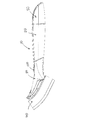
図1は、本願の実施の形態1に係る液体分配装置の斜視図である。 FIG. 1 is a perspective view of the liquid distribution device according to Embodiment 1 of the present application.
図2Aは、図1の装置の側面図である。 FIG. 2A is a side view of the apparatus of FIG.
図2Bは、図1の装置の上面図である。 FIG. 2B is a top view of the apparatus of FIG.
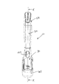
図3は、加工用ヘッドを除いた図1に示す装置の上方からの分解斜視図である。 FIG. 3 is an exploded perspective view from above of the apparatus shown in FIG. 1 excluding a processing head.
図4は、加工用ヘッドを除いた図1に示す装置の下方からの分解斜視図である。 FIG. 4 is an exploded perspective view from below of the apparatus shown in FIG. 1 excluding a processing head.
図5Aは、図1に示す装置の流量制御部の上方からの斜視図である。 FIG. 5A is a perspective view from above of a flow control unit of the apparatus shown in FIG. 1.
図5Bは、流量制御部の側面図である。 FIG. 5B is a side view of the flow control unit.
図5Cは、流量制御部の下方からの斜視図である。 FIG. 5C is a perspective view from below of the flow control unit.
図6は、図1に示す装置の組み立てられた流量制御部及びハンドルの上方からの斜視図であり、他の部材は示されていない。 FIG. 6 is a perspective view from above of the assembled flow control unit and the handle of the apparatus shown in FIG. 1, and other components are not shown.
図7は、図1に示す装置の組み立てられた流量制御部及びハンドルの下方からの斜視図であり、他の部材は示されていない。 FIG. 7 is a perspective view from below of the assembled flow control unit and the handle of the apparatus shown in FIG. 1, and other members are not shown.
図8は、図2Bに示すX−X線の断面図である。 FIG. 8 is a cross-sectional view taken along line XX shown in FIG. 2B.
図9は、図1に示す加工用ヘッドの基板の上方からの斜視図である。 FIG. 9 is a perspective view from above of the substrate of the processing head shown in FIG.
図10は、装置が流量制御部を有していない実施の形態2に係る液体分配装置の分解斜視図である。 FIG. 10 is an exploded perspective view of a liquid distribution device according to Embodiment 2 in which the device does not have a flow control unit.
本実施の形態では、本願を実施する出願人の知っている現時点での最良の方法を示す。しかしながら、本願を達成できる方法はこれのみではない。それらは図示され、例示のみの方法で、ここに記述される。 In the present embodiment, the best method known at the present time by the applicant of the present invention will be described. However, this is not the only method that can achieve the present application. They are illustrated and described herein in an illustrative manner only.
図1〜9を参照して、これらは、皿洗いへの適用を主とする液体分配装置10から成る本願のより好ましい形態を示す。装置10は、後述のように、幾つかの別々のユニットの集合体である。ここで使用される用語‘近位’は、使用中のオペレータに近い装置又はシステムの端部を参照し、一方、用語‘遠位’は、オペレータから離れた装置又はシステムの端部を参照する。装置のより下部の側は、一般に使用中に洗浄されている表面又はアイテム側に向かう側を参照し、装置のより上部の側は、一般に使用中に洗浄されている表面又はアイテムから離れて向かう側を参照している。ここで使用される用語‘横軸’は、一般に、装置の長軸にクロスする方向に延びる平面を参照する。 With reference to FIGS. 1 to 9, these show a more preferred form of the present application consisting of a liquid distribution device 10 mainly for dishwashing applications. Apparatus 10 is a collection of several separate units, as described below. As used herein, the term 'proximal' refers to the end of the device or system that is closer to the operator in use, while the term 'distal' refers to the end of the device or system that is remote from the operator. . The lower side of the device generally refers to the side facing the surface or item that is being cleaned during use, and the upper side of the device is generally away from the surface or item that is being cleaned during use. Looking side. The term 'horizontal axis' as used herein generally refers to a plane extending in a direction crossing the long axis of the device.
装置は、洗剤(例えば、食器洗い用洗剤)を貯蔵するための液体リザーバとなる封入部であるハンドル又は筐体20を有している。図3を参照し、ハンドル20は、中間部材30の内部に受けられる末端部22を有する。中間部材30は、遠位部及び近位部を有し、装置はさらに、中間部材30の遠位部に着脱可能に装着される加工用ヘッド40を有する。加工用ヘッド40と反対側のハンドル20の端部(例えば、ハンドル20の近位端部)は、それを通して、液体がハンドル20の内部に注入され得る開口部21を有し、使用時にはキャップ50で閉じられている。キャップ50は、着脱可能であり、ハンドルは必要時に洗剤で再度満たされ、キャップ50で閉じられる。
The device has a handle or
図3を参照し、ハンドル20は末端部22及び本体部24を有する。末端部22は本体部24から伸び、本体部24より小さな横断面を有する。図4を参照し、ハンドル20の末端部22は、ハンドル20の末端近くにおいて末端面26を有し、この末端面26はそこに小出し開口部又は放水口27を有する。ハンドル20は、ハンドル20の本体部24から延長する末端部22側に、第1肩部23aを有する。ハンドル20は、第1肩部よりわずかに末端側に第2肩部23bを有する。
Referring to FIG. 3, the
中間部材30は、ハンドル20の末端部22を受ける形状の内部チューブ状スリーブ37(図8に示す)を有する。中間部材30は、その近位端部において開口部32を有し、この開口部32は内部チューブ状スリーブへの開口として機能する。ハンドル20の末端部22は、雄型接続部材を形成し、中間部材30の内部チューブ状スリーブはハンドル20と中間部材30を互いに一体化するための雌型接続部材を形成する。幾つかの実施の形態では、ハンドル20の末端部22は末端方向にわずかにテーパ(先細り)しており、この場合、中間部材30の内部チューブ状スリーブがそれに応じて内側にテーパされる。図3を参照し、末端部22は、横断面で凸状の曲状上部表面22a、及び曲状上部表面22aから延長する平側面22bを有する。非対称の横断面を有することにより、末端部22は一方向でのみ中間部材30に挿入され得る。
図3及び4を参照し、ハンドル20は、第1肩部23a及び第2肩部23bの間に2つの突起部91を有し、1つの突起部91はハンドルの上側、他の突起部91は下側にある。中間部材30の内部チューブ状スリーブ37は、スナップ嵌めを介してハンドル20に中間部材30を固定的に装着するため、各突起部91を受けるため、対応する凹部38(図8に示す)を有する。スナップ嵌めは強く、一旦ハンドル20と中間部材30とが装置の製造過程で接続されると、それらはお互いから再度離れるようにはされていない。
Referring to FIGS. 3 and 4, the
図4に示すように、内部チューブ状スリーブは、末端表面39の端部で終わる。末端表面39は、そこに小出し開口部31を有し、組み立てた時、ハンドル20の放水口27に合致する。中間部材30は、中間部材30の外側を形成する外縁部80を有し、外側且つ遠位に向かって裾広がりし、末端の長方形端壁82で終わる。長方形端壁82は、装置の長手軸に平行な平面で曲げられた側縁部81を有する。内部チューブ状スリーブ37の末端表面39は、実質的に長方形端壁82と同一平面であり、より強固にするため、1以上の架橋壁83により外縁部80に結合される。
As shown in FIG. 4, the inner tubular sleeve terminates at the end of the
ハンドル20は、一般的に円形又は楕円形の横断面を有し、しかし、曲線形の上部がハンドルに人間工学に基づく形状を与える。ハンドルは遠位に先細りする。ハンドル20と中間部材30が組み立てられたとき、中間部材30は、効果的にハンドル20の脚部を供し、加工用ヘッド40が搭載され、組み立てられたとき、中間部材30は家庭用品の本体の長さに効率的に延長する。中間部材30の開口部32は、組み立てられたときハンドルの第1肩部23aに隣接し、中間部材30の外表面は、ハンドルの本体部24の外表面に付いており、ここで、各部は家庭用品になめらかな輪郭を与えるため互いに噛み合っている。
The
加工用ヘッド40は、泡状/スポンジパッド41及び基板44を有する。泡状パッド41が搭載、接着若しくはそうでなければ基板44に締め付けられる。本実施の形態の図面において、泡状パッド41は、基板44から離れて面する研磨泡立て層42(ごしごし洗うのに役立つ)を有し、しかしながら、加工用ヘッド40は、研磨泡立て層なしで非研磨泡立ての部材を備えるかもしれない。泡立てパッドの代わりに、加工用ヘッド40は、ごしごし洗うのに、又は洗浄するための部材、例えば基板44から延びる剛毛ブラシのような他の適したものをも適用できる。一体でハンドル組立部を形成するハンドル20及び中間部材30は、単純に、一の加工用ヘッドを取り外し、他のものに置換することで、種類の異なる加工用ヘッドを使用でき、この方法で、加工用ヘッドは、実行される特定の仕事に適したものを選択できる。
The
図9を参照し、基板44は、プラスチック原料のシートで形成される。基板44は、一般的に長方形状の平面又はわずかに曲がったプレートで構成される。上方拡張リム45は、末端及び基板44の2つの長側面に沿った基板の上表面の縁にまで拡張する。係止凸部46のペアが、基板44の各サイド上に1つずつ、互いの方にリム45から延びる。基板44は、さらに、基板の末端上のリム45から伸び、さらに内側に向いている遠位凸部47、基板44の近位端から延びる直立凸部48を有している。係止凸部46は、中間部材30の外縁部80の外面の各サイド上に1つある凹溝35の各対応するペアを受け、遠位凸部47は、外縁部80の末端上の末端凹部33内に受けられ、直立凸部48は、外縁部80の対応する近位凹部34内に受けられる。凸部46,47,48は、スナップ嵌めを介して加工用ヘッド40の基板44を中間部材30に装着するため、中間部材30の対応する凹部で受けられる。基板44は充分に柔軟性があり、そのようなものとして、加工用ヘッド40は凹部34から遠位凸部47を離すため、基板44を曲げることにより中間部材30から離され、その結果、基板44が凸部46,47の噛み合いからスライドで外される。
Referring to FIG. 9,
基板44の末端から遠位に延びるのは、こて縁92である。こて縁92は、例えば原料の除去に道具として使用される端部を要する皿洗いのような洗浄用途での使用が意図される。図9を参照し、基板44は小出し開口部94を有する。組み立てられたとき、基板44の小出し開口部94は、中間部材30の小出し開口部31及びハンドル20の放水口27の箇所に位置し、その結果、液体は、ハンドル20のリザーバから分配され、加工用ヘッド40から出る。
Extending distally from the distal end of
装置10はさらに、ハンドルからの液流を制御するための流量制御部100を有する。流量制御部100は、中間部材30に連結され、ハンドル20からの液体の分配をブロックする閉位置と、少なくともハンドル20からの液体の分配をブロックしない第1開位置との間で可動である。図5Aを参照し、流量制御部100は、本体部102、バルブ部110、及びアクチュエータ部120を有する1片のプラスチック成型材として供される。図6を参照し、本体部102は、近位及び遠位の開口端を伴う通し穴を有するスリーブで形成され、ハンドル20の末端部22を受ける形状とされている本体部102であり、その結果、流量制御部100は、組立時において末端部22の周囲で受けられる。
The device 10 further has a
アクチュエータ部120は、組立てられたとき、ユーザにアクセスできるように、本体部102の上側面から突出した突出部を有する。中間部材30は卵型スロット95を有し、その形状のためアクチュエータ部120がそこから突出し、ユーザがアクチュエータ部を動かすことで、流量制御部100を調節する。
The
バルブ部110は、本体部102の下側から伸びた舌部を有する。バルブ部110は、サイズの異なる第1穴部112及び第2穴部114を有する。流量制御部100の第2穴部114は、穴形状の27,31及び94より大きくない。組み立てられたとき、流量制御部100は、中間部材30の内部チューブ状スリーブ37内に位置し、流量制御部100の本体部102でハンドルの末端部22を受け、アクチュエータ部120はスロット95を介して突出している。ハンドルの末端部22の下側は、組立時に流量制御部100のバルブ部110を受ける傾斜凹状部28を有する。
The
流量制御部100はスライド動作を介して、ハンドル20及び中間部材30と相対して近位及び遠位に、閉位置と第1,第2開位置との間を、直線的に可動する。閉位置では、図1及び図8に示すように、バルブ部110のブロック体側の末端がハンドル20の放水口27側であり、それにより、液体がハンドル20から流れ出るのがブロックされる。アクチュエータ部120は、ユーザが流量制御部100を遠位に動かすことで第1開位置に進み、ここで、第1穴部112はハンドル20の放水口27に合致し、そのために、液体がハンドルから、穴部112、中間部材の小出し開口部31、及び加工用ヘッド40の小出し開口部94を介して流れる。アクチュエータ部120は、第1開位置から第2開位置に遠位に動き、ここで、第2穴部114はハンドル20の放水口27に合致し、そのために、液体がハンドルから穴部114、小出し開口部31、及び加工用ヘッド40の小出し開口部94を介して流れる。第2穴部114が第1穴部112より大きいため、第2開位置では速い流量率の構造に対応し、一方、第1開位置では遅い流量率の構造に対応する。これによって、ユーザは第1及び第2で別々の流量制御の構造を選択できる。さらに、異なるサイズの穴部が、もちろん、さらに別々の流量制御の構造を供するため、バルブ部に形成されることも考え得る。
The
図5Aを参照し、流量制御部100は、本体部102の下側の内表面から上方に突出した戻り止め部104を有する。図4を参照し、ハンドルの末端部22の下側の表面には、オペレータによって選択される、閉位置、第1開位置又は第2開位置で流量制御部100を保持するための戻り受け部104と嵌合するための第1、第2及び第3戻り受け凹部97a、97b、97cを有する。戻り受け凹部97a、97b、97cは、ハンドルの長手軸に平行なラインで配列される。戻り受け部104が第1戻り受け凹部97aに固定されると、流量制御部は閉位置となる。戻り受け部104が第2戻り受け凹部97bに固定されると、流量制御部は第1開位置となる。戻り受け部104が第3戻り受け凹部97cに固定されると、流量制御部は第2開位置となる。一の凹部から隣接する凹部に移動するため、すなわち、別々の位置の間で流量制御部を動かすため、弱い力がアクチュエータ部120に対してオペレータにより戻り受け部104を動かすため適用されることが要される。
Referring to FIG. 5A,
図1を参照し、中間部材30は、流量制御部100がその間で動かされる3つの別々の流量制御の形状を示すため、ユーザに可視できる外表面上に、3つの位置マーカ96a、96b、96cを有する。この実施の形態では、位置マーカ96a、96b、96cは中間部材30の外表面から出ており、その結果、オペレータは位置マーカに触れることができるが、位置マーカは必ずしも突き出る形状とする必要はなく、中間部材30の外表面と同一平面上又は外表面の窪みでもよい。位置マーカ96a、96b、96cは円形マークであり、末端方向に近づくようなラインで配置され、各位置マーカは、近位より遠位のものがより大きくなる。アクチュエータ部120が第1位置マーカ96aに配置されるとき、これは、流量制御部が閉位置にあるとオペレータに示している。アクチュエータ部120が第2位置マーカ96bに配置されるとき、これは、流量制御部が第1開位置(例えば低い流れの形状)にあるとオペレータに示している。アクチュエータ部120が第3位置マーカ96cに配置されるとき、これは、流量制御部が第2開位置(例えば早い流れの形状)にあるとオペレータに示している。
Referring to FIG. 1, the
キャップ50は、バヨネット結合を介してハンドル20に取り付けられる。これは、上側及び下側が互いに対称形ではないキャップ50が、ハンドル20に対して好みの方向でハンドル20に取り付くことを確約する。図3を参照し、キャップ50は、キャップの内側リムの反対側から内方に突出する2つの雄型バヨネット凸部52を有する。ハンドル20に近い側の端部は、キャップをハンドルに固定するため、キャップ上のバヨネット凸部52に係合する2つの対応する雌型バヨネット受け部54を有する。もちろん、キャップ50は、他の好ましい装着手段を用いてハンドル20に装着するかもしれず、ここで、キャップ50は例えば螺合によって、ハンドル20に脱着可能、封止可能に取り付けられる。
The
装置は、リザーバから液体が漏れることを防止するため、使用と使用との間では、流量制御部100を閉位置にして放置され得る。ユーザが例えば皿洗いのために装置を使用するとき、ユーザは流量制御部100のアクチュエータ部120を、洗剤の好ましい液量に応じて、第1又は第2開位置に移動する。一度、流量制御部100が第1又は第2開位置になると、液体がハンドルの放水口27、流量制御部100の選択された穴部112,114を介して、液体を分配する小出し開口部31,94を介して、加工用ヘッドから流れ出る。
The device may be left with the
上記実施の形態において、流量制御部100は、閉位置と開位置との間を直線的に可動する。しかしながら、流量制御部100は必ずしも直線的に動く必要はなく、これらの位置の間を回転可能に動く形状でも良い。
In the above embodiment, the
ハンドル20と中間部材30は、好ましくは注入成形が良い。装置の製造過程で、組立て用の各ユニットが作られた後、それらが上述する方法で一体に組み立てられる。というのも、中間部材30は、ハンドル20からは別部材であり、中間部材30は、異なる形状及び/又は異なる用途に適したサイズの範囲から選択でき得る。例えば、図1〜9に示す中間部材は一般的に皿洗いに適しているが、ビン首の内に入るためにより狭い中間部材30が、組立時に使用され得て、その結果、装置がビン洗浄装置として使用され得る。
The
装置は流量制御部100を必ずしも有するものではない。図10を参照し、液体分配装置10は図1〜9に示すものと似ているが、流量制御部100を有していない。同じ参照番号が上記の実施の形態に対応した形状を示すために使用される。図10の組み立て物は、中間部材30の中で受けられる末端部22があるハンドル20を有し、さらに、この組み立て物は、中間部材30に取り付ける加工用ヘッド40を有する。従って、装置は、液体を貯めるための中空のハンドル20と、そこに組立て、また異なる形状及び/又は異なる使用に適したサイズの2以上の中間部材から製造工程において選択され得る初めは別々の中間部材30と、のモジュール組立体から作られるのを利用する。
The device does not necessarily have the
図1〜9に示す以外の好ましい手段が、加工用ヘッド40を中間部材30に取り外し可能に取り付けるために用いられるかもしれない。
Preferred means other than those shown in FIGS. 1-9 may be used to removably attach the
Claims (18)
前記中空のハンドルは、その中に液体リザーバとなる封入部を供し、末端部、及び前記末端部に位置する放水口を有し、
前記加工用ヘッドは、液体を分配するための小出し開口部を有し、
前記中間部材は、その内部で前記ハンドルの前記末端部を受ける形状を成し、
前記加工用ヘッドは、前記中間部材に取り付けられ、
前記中間部材は小出し開口部を有し、この中間部材の前記小出し開口部は、組み立てられたときに、前記ハンドルの前記放水口及び前記加工用ヘッドの前記小出し開口部の位置に合致しており、
前記装置は、さらに、前記ハンドルからの液体の流れを制御するための流量制御部を有し、前記流量制御部は、前記流れを選択的に制御するため前記ハンドルの放水口に対して可動であり、
前記流量制御部は、前記中間部材内で実質的に受けられ、前記流量制御部は、前記ハンドルからの液体の流量を制御するために前記ハンドルに対して遠位と近位にスライド動作により直線的に移動可能であり、前記流量制御部は、そこを通して前記ハンドルの前記末端部の少なくとも一部を受けるための通し穴を有する、ことを特徴とする液体分配装置。 A liquid dispensing device having a hollow handle, a processing head into which liquid is dispensed, and an intermediate member,
The hollow handle provides an enclosure therein serving as a liquid reservoir, has a distal end, and a water outlet located at the distal end,
The processing head has a dispensing opening for distributing liquid,
The intermediate member is configured to receive the distal end of the handle therein.
The processing head is attached to the intermediate member,
It said intermediate member has a dispensing opening, the dispensing opening of the intermediate member, when assembled, is consistent with the position of the dispensing opening of the outlets and the machining head of the handle ,
The apparatus further comprises a flow control for controlling the flow of liquid from the handle, wherein the flow control is movable with respect to a water outlet of the handle to selectively control the flow. Yes,
The flow control is substantially received within the intermediate member, the flow control being linearly slid distally and proximally with respect to the handle to control the flow of liquid from the handle. Liquid dispensing device, characterized in that the flow control is movable and the flow control has a through-hole for receiving at least a part of the distal end of the handle therethrough .
前記流量制御部は、別々の第1流量制御位置及び第2流量制御位置に対応する第1開位置及び第2開位置の間で動き、ここで前記流量制御部が前記第1開位置のとき、前記第1穴部は前記ハンドルの放水口に合致し、前記第2開位置のとき、前記第2穴部は前記ハンドルの放水口に合致する、ことを特徴とする請求項2乃至請求項4のいずれか一項に記載の液体分配装置。 The valve portion of the flow rate control portion has at least a first hole portion and a second hole portion of different sizes, and the valve portion is configured such that the first hole portion and the second hole portion are provided at a water outlet of the handle. Movable with respect to the outlet of the handle to selectively match;
The flow control unit moves between a first open position and a second open position corresponding to separate first and second flow control positions, wherein the flow control unit is in the first open position. the first hole is consistent with the outlets of the handle, the case of the second open position, claims 2 to which the second hole portion is characterized in that, to match the outlets of the handle The liquid distribution device according to any one of claims 4 to 7.
前記流量制御部及び隣接の表面の一つは、戻り受けを有し、他のものは戻り受け動作を介して選択された位置で前記流量制御部を維持するための前記戻り受けを受けるための少なくとも1つの戻り受け凹部を有する、ことを特徴とする請求項4乃至5のいずれか一項に記載の液体分配装置。 The flow control unit maintains the open position or the closed position via the return operation,
The flow control and one of the adjacent surfaces have a return catch, the other for receiving the return catch for maintaining the flow control at a selected position via a return receiving operation. The liquid distribution device according to any one of claims 4 to 5 , further comprising at least one return receiving recess.
The flow control unit has an actuator unit, and the actuator unit can be used by a user. Here, the movement of the actuator unit by the user is such that the valve unit of the flow control unit is connected to the water outlet of the handle. The liquid dispensing device according to any one of claims 2 to 7, wherein the liquid dispensing device is movable with respect to the liquid dispenser.
The liquid dispensing device according to any one of claims 8 to 10, wherein the actuator unit is movable distally with respect to the handle to move the flow control unit to an open position. .
The liquid dispensing device according to any of claims 2 to 11, wherein the distal end of the handle has a recessed area for receiving the valve part of the flow control part.
前記キットは、異なるサイズ及び/又は形状の2以上の前記中間部材を備える、ことを特徴とする組立キット。 An assembly kit for a liquid dispensing device according to any one of the preceding claims , wherein the kit comprises assembly parts according to any of the claims,
An assembly kit, wherein the kit comprises two or more of the intermediate members of different sizes and / or shapes.
Applications Claiming Priority (2)
| Application Number | Priority Date | Filing Date | Title |
|---|---|---|---|
| GB1411689.1A GB2526886B (en) | 2014-07-01 | 2014-07-01 | Improvements to fluid-dispensing apparatus |
| GB1411689.1 | 2014-07-01 |
Publications (3)
| Publication Number | Publication Date |
|---|---|
| JP2016013435A JP2016013435A (en) | 2016-01-28 |
| JP2016013435A5 JP2016013435A5 (en) | 2018-08-02 |
| JP6670050B2 true JP6670050B2 (en) | 2020-03-18 |
Family
ID=51410430
Family Applications (1)
| Application Number | Title | Priority Date | Filing Date |
|---|---|---|---|
| JP2015129315A Expired - Fee Related JP6670050B2 (en) | 2014-07-01 | 2015-06-26 | Liquid distribution device |
Country Status (6)
| Country | Link |
|---|---|
| US (1) | US9526326B2 (en) |
| EP (1) | EP2962615B1 (en) |
| JP (1) | JP6670050B2 (en) |
| AU (1) | AU2015203594B2 (en) |
| ES (1) | ES2621265T3 (en) |
| GB (1) | GB2526886B (en) |
Families Citing this family (10)
| Publication number | Priority date | Publication date | Assignee | Title |
|---|---|---|---|---|
| USD815439S1 (en) * | 2015-03-06 | 2018-04-17 | The Libman Company | Soap dispenser |
| USD828969S1 (en) * | 2016-10-14 | 2018-09-18 | Michael Robert Brady | Dish cleaner with suction cup |
| USD825931S1 (en) | 2017-02-10 | 2018-08-21 | FC Brands Ltd. | Foaming brush |
| USD854269S1 (en) * | 2018-04-20 | 2019-07-16 | 3M Innovative Properties Company | Cleaning tool |
| DK201970154A1 (en) | 2019-03-06 | 2020-09-08 | Imbox Shoecare As | After treatment system |
| AT522236B1 (en) * | 2019-03-13 | 2022-02-15 | Georg Hagleitner Hans | Dispenser set with a dispensing device and at least one container containing a pumpable medium |
| US10631625B1 (en) | 2019-04-01 | 2020-04-28 | Hala F.H.Y. Alhajji | Vibrating dispensing hairbrush |
| USD948877S1 (en) * | 2019-10-17 | 2022-04-19 | Magellan Home-Goods, Ltd. | Grill brush |
| US11944186B2 (en) | 2021-03-12 | 2024-04-02 | Burns Brothers LLC | Flexible cleaner |
| USD970224S1 (en) * | 2022-08-10 | 2022-11-22 | Xiaoqun Luo | Dish brush handle |
Family Cites Families (42)
| Publication number | Priority date | Publication date | Assignee | Title |
|---|---|---|---|---|
| US729515A (en) | 1902-10-21 | 1903-05-26 | Alfred Steele | Brush. |
| GB141183A (en) | 1919-03-31 | 1920-04-15 | Justine Breeden Mcnamara | An improved device for washing and cleaning crockery or other articles or bodies |
| US2823401A (en) * | 1954-01-15 | 1958-02-18 | O'higgins Michael | Tooth brush |
| US3653779A (en) | 1970-03-30 | 1972-04-04 | Gilbert Schwartzman | Disc valve for applicator |
| US3661468A (en) | 1970-05-25 | 1972-05-09 | Gilbert Schwartzman | Fluid applicator having wine-cup shaped valve assembly |
| IT970618B (en) | 1971-12-03 | 1974-04-20 | Garcia Mila Palaudarias J | AUTOMATIC DEVICE FOR CAPPING CONTAINERS CONTAINING LIQUIDS AT ATMOSPHERIC PRESSURE |
| US4053242A (en) | 1976-03-18 | 1977-10-11 | The Procter & Gamble Company | Disposable product applicator and dispensing package therefor |
| US4077725A (en) * | 1976-05-27 | 1978-03-07 | Slautterback Ernest G | Shoe polish applicator |
| US4135831A (en) * | 1977-01-14 | 1979-01-23 | Jack Reitknecht | Laminated fountain toothbrush with barrier |
| USD267282S (en) | 1980-10-09 | 1982-12-14 | Abbott Laboratories | Sponge applicator, or the like |
| US4692047A (en) * | 1983-04-20 | 1987-09-08 | Sasuke Endo | Brush for applying material in liquid or emulsion form |
| GB2160092A (en) * | 1984-05-08 | 1985-12-18 | Alphaplan Ltd | Cleaning device |
| GB2159698A (en) | 1984-05-08 | 1985-12-11 | Alphaplan Ltd | Cleaning device |
| US5120148A (en) | 1986-03-10 | 1992-06-09 | The West Company, Incorporated | Applicator assembly |
| DE3700113A1 (en) * | 1987-01-03 | 1988-07-14 | Rothweiler Gmbh & Co Kg Geb | HAND BRUSHES |
| JPS63143209U (en) | 1987-03-09 | 1988-09-21 | ||
| USD306924S (en) | 1987-04-23 | 1990-03-27 | Shapton Robert W | Fluid dispensing sponge mop for use on a car |
| GB9319686D0 (en) * | 1993-09-23 | 1993-11-10 | Taghavi Said | Toothbrush with toothpaste reservoir and bristle adapters |
| US5509744A (en) * | 1995-06-23 | 1996-04-23 | Frazier; Thomas G. | Liquid applicator with slide ring activator |
| USD387704S (en) | 1996-09-27 | 1997-12-16 | The Libman Company | Liquid-dispensing scrub brush |
| USD389625S (en) | 1996-11-12 | 1998-01-20 | Rubbermaid Incorporated | Sponge mop |
| AU9362198A (en) | 1998-06-09 | 1999-12-30 | Georg Rabatic Miso | Tooth-brush with container for tooth-paste |
| GB2363977B (en) * | 2000-06-20 | 2003-07-02 | London Oil Refining Company Lt | A toilet cleaning apparatus |
| US20040105715A1 (en) * | 2000-10-27 | 2004-06-03 | Duncan Spelman | Cleaning utensils |
| GB2369560B (en) | 2000-11-24 | 2002-12-18 | Easy Do Products Ltd | Improvements to implements for cleaning polishing or sanding |
| US20020186996A1 (en) * | 2001-06-12 | 2002-12-12 | Aramark Corporation | Dispenser |
| BE1014287A6 (en) * | 2001-07-06 | 2003-08-05 | Waak Beschutte Werkplaats Vzw | Cleaning equipment and parts for forming such cleaning unit. |
| GB2395680B (en) | 2002-11-28 | 2004-10-27 | Easy Do Products Ltd | Improvements to handheld utensils for cleaning |
| US7146676B2 (en) | 2003-09-16 | 2006-12-12 | 3M Innovative Properties Company | Cleaning device with disposable pad |
| US20050147461A1 (en) * | 2003-09-22 | 2005-07-07 | Glover J. S. | Dispensing brush |
| USD511626S1 (en) | 2003-10-14 | 2005-11-22 | Hayco Manufacturing Limited | Handle with base for cleaning implement |
| US20070212161A1 (en) * | 2006-03-08 | 2007-09-13 | Carlson Karen A | Pool tile cleaning device and method |
| US7771135B2 (en) * | 2006-03-23 | 2010-08-10 | The Libman Company | Scrubber and cleaning fluid dispenser assembly |
| CA2652604A1 (en) * | 2006-06-01 | 2007-12-06 | The Decor Corporation Pty Ltd | A cleaning tool |
| US8262307B1 (en) * | 2006-06-22 | 2012-09-11 | Cross Thomas E | Attachable condiment applicators and kit therefor |
| USD549412S1 (en) | 2006-10-10 | 2007-08-21 | Conopco, Inc. | Cleansing implement |
| USD558417S1 (en) | 2007-01-18 | 2007-12-25 | The Libman Company | Soap dispenser |
| KR200450995Y1 (en) * | 2008-08-26 | 2010-11-16 | (주)연우 | A pencil type cosmetics case |
| US8550738B2 (en) * | 2008-08-28 | 2013-10-08 | Hct Asia Ltd | Flow-through dispenser with helical actuation |
| US7677827B1 (en) * | 2008-09-29 | 2010-03-16 | Oleg Manukian | Toothbrush with toothpaste dispenser |
| USD606269S1 (en) | 2008-10-04 | 2009-12-15 | Easy-Do Products Limited | Hand-held cleaning utensil with removable sponge head |
| US7717635B1 (en) * | 2008-11-12 | 2010-05-18 | Jennifer Schmidig | Liquid dispensing brush |
-
2014
- 2014-07-01 GB GB1411689.1A patent/GB2526886B/en active Active
-
2015
- 2015-06-26 JP JP2015129315A patent/JP6670050B2/en not_active Expired - Fee Related
- 2015-06-26 AU AU2015203594A patent/AU2015203594B2/en active Active
- 2015-06-30 EP EP15174492.7A patent/EP2962615B1/en active Active
- 2015-06-30 US US14/788,197 patent/US9526326B2/en active Active
- 2015-06-30 ES ES15174492.7T patent/ES2621265T3/en active Active
Also Published As
| Publication number | Publication date |
|---|---|
| GB2526886A (en) | 2015-12-09 |
| AU2015203594A1 (en) | 2016-01-21 |
| EP2962615A1 (en) | 2016-01-06 |
| EP2962615B1 (en) | 2017-03-08 |
| ES2621265T3 (en) | 2017-07-03 |
| US9526326B2 (en) | 2016-12-27 |
| JP2016013435A (en) | 2016-01-28 |
| GB201411689D0 (en) | 2014-08-13 |
| AU2015203594B2 (en) | 2019-01-17 |
| GB2526886B (en) | 2016-05-11 |
| US20160000213A1 (en) | 2016-01-07 |
Similar Documents
| Publication | Publication Date | Title |
|---|---|---|
| JP6670050B2 (en) | Liquid distribution device | |
| US11771294B2 (en) | Tool assembly comprising universal handle and interchangeable tool heads | |
| US9326655B2 (en) | Multi-function cleaning apparatus | |
| US8186898B2 (en) | Plural nozzle cleaning implement | |
| AU2006285437B2 (en) | Surface cleaning device with liquid dispenser | |
| US8684619B2 (en) | Cleaning device having plural and customizable cleaning surfaces | |
| US20060133886A1 (en) | Shampooing brush | |
| US10285567B2 (en) | Dish scrubber with changeable scrub head | |
| JP2017516614A (en) | Fluid dispensing and cleaning equipment | |
| US9428889B2 (en) | Household faucet spray | |
| US6602010B1 (en) | Liquid soap sprayer and sponge attachment for water sprayer | |
| US20150001255A1 (en) | Water supply apparatus for water spray container |
Legal Events
| Date | Code | Title | Description |
|---|---|---|---|
| A521 | Request for written amendment filed |
Free format text: JAPANESE INTERMEDIATE CODE: A523 Effective date: 20180621 |
|
| A621 | Written request for application examination |
Free format text: JAPANESE INTERMEDIATE CODE: A621 Effective date: 20180621 |
|
| A977 | Report on retrieval |
Free format text: JAPANESE INTERMEDIATE CODE: A971007 Effective date: 20190724 |
|
| A131 | Notification of reasons for refusal |
Free format text: JAPANESE INTERMEDIATE CODE: A131 Effective date: 20190730 |
|
| A521 | Request for written amendment filed |
Free format text: JAPANESE INTERMEDIATE CODE: A523 Effective date: 20191028 |
|
| TRDD | Decision of grant or rejection written | ||
| A01 | Written decision to grant a patent or to grant a registration (utility model) |
Free format text: JAPANESE INTERMEDIATE CODE: A01 Effective date: 20200204 |
|
| A61 | First payment of annual fees (during grant procedure) |
Free format text: JAPANESE INTERMEDIATE CODE: A61 Effective date: 20200228 |
|
| R150 | Certificate of patent or registration of utility model |
Ref document number: 6670050 Country of ref document: JP Free format text: JAPANESE INTERMEDIATE CODE: R150 |
|
| LAPS | Cancellation because of no payment of annual fees |