JP6668552B2 - Air conditioner indoor unit - Google Patents
Air conditioner indoor unit Download PDFInfo
- Publication number
- JP6668552B2 JP6668552B2 JP2019503366A JP2019503366A JP6668552B2 JP 6668552 B2 JP6668552 B2 JP 6668552B2 JP 2019503366 A JP2019503366 A JP 2019503366A JP 2019503366 A JP2019503366 A JP 2019503366A JP 6668552 B2 JP6668552 B2 JP 6668552B2
- Authority
- JP
- Japan
- Prior art keywords
- angle
- indoor unit
- louver
- air conditioner
- outlets
- Prior art date
- Legal status (The legal status is an assumption and is not a legal conclusion. Google has not performed a legal analysis and makes no representation as to the accuracy of the status listed.)
- Active
Links
- 238000007664 blowing Methods 0.000 claims description 27
- 238000010438 heat treatment Methods 0.000 claims description 9
- 238000003756 stirring Methods 0.000 claims description 4
- 239000011810 insulating material Substances 0.000 description 9
- PPBRXRYQALVLMV-UHFFFAOYSA-N Styrene Chemical compound C=CC1=CC=CC=C1 PPBRXRYQALVLMV-UHFFFAOYSA-N 0.000 description 4
- 230000000694 effects Effects 0.000 description 4
- 230000001143 conditioned effect Effects 0.000 description 3
- 238000005516 engineering process Methods 0.000 description 3
- 239000003507 refrigerant Substances 0.000 description 3
- XLYOFNOQVPJJNP-UHFFFAOYSA-N water Substances O XLYOFNOQVPJJNP-UHFFFAOYSA-N 0.000 description 3
- 238000004378 air conditioning Methods 0.000 description 2
- 238000001816 cooling Methods 0.000 description 2
- 239000006260 foam Substances 0.000 description 2
- 230000002093 peripheral effect Effects 0.000 description 2
- 230000003247 decreasing effect Effects 0.000 description 1
- 238000010586 diagram Methods 0.000 description 1
- 230000002452 interceptive effect Effects 0.000 description 1
- 238000012986 modification Methods 0.000 description 1
- 230000004048 modification Effects 0.000 description 1
- 238000005057 refrigeration Methods 0.000 description 1
- 239000011347 resin Substances 0.000 description 1
- 229920005989 resin Polymers 0.000 description 1
- 230000000630 rising effect Effects 0.000 description 1
- 239000000126 substance Substances 0.000 description 1
- 238000010977 unit operation Methods 0.000 description 1
Images


Classifications
-
- F—MECHANICAL ENGINEERING; LIGHTING; HEATING; WEAPONS; BLASTING
- F24—HEATING; RANGES; VENTILATING
- F24F—AIR-CONDITIONING; AIR-HUMIDIFICATION; VENTILATION; USE OF AIR CURRENTS FOR SCREENING
- F24F1/00—Room units for air-conditioning, e.g. separate or self-contained units or units receiving primary air from a central station
- F24F1/0007—Indoor units, e.g. fan coil units
- F24F1/0011—Indoor units, e.g. fan coil units characterised by air outlets
- F24F1/0014—Indoor units, e.g. fan coil units characterised by air outlets having two or more outlet openings
-
- F—MECHANICAL ENGINEERING; LIGHTING; HEATING; WEAPONS; BLASTING
- F24—HEATING; RANGES; VENTILATING
- F24F—AIR-CONDITIONING; AIR-HUMIDIFICATION; VENTILATION; USE OF AIR CURRENTS FOR SCREENING
- F24F1/00—Room units for air-conditioning, e.g. separate or self-contained units or units receiving primary air from a central station
- F24F1/0007—Indoor units, e.g. fan coil units
- F24F1/0043—Indoor units, e.g. fan coil units characterised by mounting arrangements
- F24F1/0047—Indoor units, e.g. fan coil units characterised by mounting arrangements mounted in the ceiling or at the ceiling
-
- F—MECHANICAL ENGINEERING; LIGHTING; HEATING; WEAPONS; BLASTING
- F24—HEATING; RANGES; VENTILATING
- F24F—AIR-CONDITIONING; AIR-HUMIDIFICATION; VENTILATION; USE OF AIR CURRENTS FOR SCREENING
- F24F11/00—Control or safety arrangements
- F24F11/50—Control or safety arrangements characterised by user interfaces or communication
- F24F11/56—Remote control
-
- F—MECHANICAL ENGINEERING; LIGHTING; HEATING; WEAPONS; BLASTING
- F24—HEATING; RANGES; VENTILATING
- F24F—AIR-CONDITIONING; AIR-HUMIDIFICATION; VENTILATION; USE OF AIR CURRENTS FOR SCREENING
- F24F11/00—Control or safety arrangements
- F24F11/70—Control systems characterised by their outputs; Constructional details thereof
- F24F11/72—Control systems characterised by their outputs; Constructional details thereof for controlling the supply of treated air, e.g. its pressure
- F24F11/74—Control systems characterised by their outputs; Constructional details thereof for controlling the supply of treated air, e.g. its pressure for controlling air flow rate or air velocity
-
- F—MECHANICAL ENGINEERING; LIGHTING; HEATING; WEAPONS; BLASTING
- F24—HEATING; RANGES; VENTILATING
- F24F—AIR-CONDITIONING; AIR-HUMIDIFICATION; VENTILATION; USE OF AIR CURRENTS FOR SCREENING
- F24F11/00—Control or safety arrangements
- F24F11/70—Control systems characterised by their outputs; Constructional details thereof
- F24F11/72—Control systems characterised by their outputs; Constructional details thereof for controlling the supply of treated air, e.g. its pressure
- F24F11/79—Control systems characterised by their outputs; Constructional details thereof for controlling the supply of treated air, e.g. its pressure for controlling the direction of the supplied air
-
- F—MECHANICAL ENGINEERING; LIGHTING; HEATING; WEAPONS; BLASTING
- F24—HEATING; RANGES; VENTILATING
- F24F—AIR-CONDITIONING; AIR-HUMIDIFICATION; VENTILATION; USE OF AIR CURRENTS FOR SCREENING
- F24F13/00—Details common to, or for air-conditioning, air-humidification, ventilation or use of air currents for screening
- F24F13/08—Air-flow control members, e.g. louvres, grilles, flaps or guide plates
- F24F13/10—Air-flow control members, e.g. louvres, grilles, flaps or guide plates movable, e.g. dampers
- F24F13/14—Air-flow control members, e.g. louvres, grilles, flaps or guide plates movable, e.g. dampers built up of tilting members, e.g. louvre
Landscapes
- Engineering & Computer Science (AREA)
- Chemical & Material Sciences (AREA)
- Combustion & Propulsion (AREA)
- Mechanical Engineering (AREA)
- General Engineering & Computer Science (AREA)
- Human Computer Interaction (AREA)
- Physics & Mathematics (AREA)
- Fluid Mechanics (AREA)
- Air Conditioning Control Device (AREA)
- Air-Flow Control Members (AREA)
- Air Filters, Heat-Exchange Apparatuses, And Housings Of Air-Conditioning Units (AREA)
Description
本発明は、空気調和機の室内機に係り、特に、複数の吹出口を有し、それぞれの吹出口に風向を制御するためのルーバを備えるものに関する。 The present invention relates to an indoor unit of an air conditioner, and more particularly to an air conditioner having a plurality of outlets, each of which has a louver for controlling a wind direction.
従来の空気調和機として、複数の吹出口(例えば4つ)を備える空気調和機の室内機があり、このような室内機では暖房運転時に、暖房する室内の温度ムラを改善するため、複数の吹出口から吹き出される加熱された空気の吹出し方向をそれぞれ異なる風向とすることで、空気の攪拌動作を行うようにしたものがある。 2. Description of the Related Art As a conventional air conditioner, there is an air conditioner indoor unit having a plurality of outlets (for example, four outlets). In such an indoor unit, in order to improve temperature unevenness in a room to be heated during a heating operation, a plurality of air conditioners are provided. There is an air stirrer in which heated air blown out from an outlet is blown in different directions so that the air is stirred.
また、複数の吹出口のうち、一部の吹出口のルーバ角度を通常運転では使用しない角度にして、開口面積を狭め、残りの吹出口に風量を集中させて、風速を高めるようにしたものもある。 In addition, among the plurality of outlets, the louver angle of some of the outlets is set to an angle not used in normal operation, the opening area is narrowed, the air volume is concentrated on the remaining outlets, and the wind speed is increased. There is also.
この種従来技術としては、特許第6135734号公報(特許文献1)に記載のものがあり、この特許文献1のものでは、暖房運転時において、室内負荷が高い場合、室内機の吹出口の一部を、開口面積が小さくなるように、ルーバを、最大の下吹き位置よりも更に大きな角度に回動させる気流ブロック位置とし、残りの吹出口のルーバを水平吹き位置にするように制御している。
As this kind of conventional technology, there is a technology described in Japanese Patent No. 6135733 (Patent Document 1). In the technology disclosed in
前記気流ブロック位置とは、ルーバが通常使用する最大角度(下吹き)から更に開き、ルーバの羽根が吹出口の中に深く入り込む位置である。このように構成することにより、ルーバの羽根で気流の流路を塞ぐようにしている。ルーバが気流ブロック位置にある吹出口では吹出風量が大幅に減るので、残りの吹出口における風速が高まり、通常より遠くに吹出空気を到達させることができる。 The airflow block position is a position where the louver is further opened from a maximum angle (low blow) which is normally used, and the blade of the louver enters deeply into the outlet. With this configuration, the airflow passage is closed by the louver blades. At the outlet where the louver is at the position of the airflow block, the amount of blown air is greatly reduced, so that the wind speed at the remaining outlets increases, and the blown air can reach farther than usual.
しかし、上記特許文献1に記載されているような気流ブロック位置までルーバを回転させようとすると、通常の室内機では、ルーバが、断熱材などで構成されている吹出口の壁面に接触する。このため、ルーバを前記気流ブロック位置まで回転させることができるようにするためには、ルーバ付近の吹出口の内部構造を変更する必要がある。
However, when trying to rotate the louver to the airflow block position as described in
また、一部の吹出口のルーバを全閉位置(運転停止時の位置)とすることで、残りの吹出口における風速を増加させることも考えられるが、ルーバを全閉位置にすると風圧によってルーバがたわんでしまう課題がある。 It is also conceivable to increase the wind speed at the remaining outlets by setting the louvers of some of the outlets to the fully closed position (the position when operation is stopped). There is a problem that warps.
本発明の目的は、複数の吹出口の一部の吹出口からの高速吹出しを可能にしつつ、各吹出口に設けられているルーバのたわみを抑制することもできる空気調和機の室内機を得ることにある。 An object of the present invention is to provide an indoor unit of an air conditioner that enables high-speed blowing from a part of a plurality of outlets while suppressing deflection of a louver provided at each outlet. It is in.
上記目的を達成するため、本発明は、複数の吹出口と、前記各吹出口に設けられ吹出し方向を調節可能に構成されている複数のルーバと、を備える空気調和機の室内機において、室内機の停止時には前記ルーバは前記吹出口を閉じる方向に回動されると共に、前記吹出口を閉じる方向に回動された室内機停止時のルーバ角度を全閉角度とし、前記室内機の運転時に前記ルーバの動作を設定するためのリモコンを備え、前記リモコンで設定可能な前記ルーバの角度のうちの最小角度を第1角度とし、最大角度を第2角度としたとき、予め定めた所定の運転条件では、複数の前記吹出口の内、一部の吹出口のルーバ角度を、室内機停止時のルーバ角度である全閉角度よりも大きく且つ前記第1角度よりも小さい第3角度に設定され、他の前記吹出口のルーバは前記リモコンから設定可能なルーバ動作を行うことを特徴とする。 In order to achieve the above object, the present invention relates to an indoor unit of an air conditioner including a plurality of outlets, and a plurality of louvers provided in each of the outlets and configured to be capable of adjusting a blowing direction. When the unit is stopped, the louver is rotated in a direction to close the air outlet, and the louver angle when the indoor unit is stopped, which is turned in the direction to close the air outlet, is set to a fully closed angle, and when the indoor unit is operated, A remote controller for setting the operation of the louver, a predetermined predetermined operation when a minimum angle among the louver angles that can be set by the remote controller is a first angle and a maximum angle is a second angle; Under the conditions, the louver angle of some of the plurality of outlets is set to a third angle that is larger than the fully closed angle that is the louver angle when the indoor unit is stopped and smaller than the first angle. , The other said blowing The louvers and performs a configurable louver operation from the remote controller.
本発明の他の特徴は、複数の吹出口と、前記各吹出口に設けられ吹出し方向を調節可能に構成されている複数のルーバと、を備える空気調和機の室内機において、室内機の停止時には前記ルーバは前記吹出口を閉じる方向に回動されると共に、前記吹出口を閉じる方向に回動された室内機停止時のルーバ角度を全閉角度とし、前記室内機の運転時に前記ルーバをオートスイングさせる機能を有し、前記オートスイング時の前記ルーバの最小角度を第1角度とし、最大角度を第2角度としたとき、予め定めた所定の運転条件では、複数の前記吹出口の内、一部の吹出口のルーバ角度を、室内機停止時のルーバ角度である全閉角度よりも大きく且つ前記第1角度よりも小さい第3角度に設定され、他の前記吹出口のルーバはオートスイング或いは任意の角度に設定されることにある。 Another feature of the present invention is an indoor unit of an air conditioner including a plurality of outlets, and a plurality of louvers provided at each of the outlets and configured to be capable of adjusting a blowing direction. Sometimes, the louver is rotated in the direction to close the air outlet, and the louver angle at the time of stopping the indoor unit, which is turned in the direction to close the air outlet, is set to the fully closed angle, and the louver is operated during the operation of the indoor unit. When the minimum angle of the louver at the time of the automatic swing is set to the first angle and the maximum angle is set to the second angle, under a predetermined operating condition, out of the plurality of outlets, The louver angles of some of the outlets are set to a third angle larger than the fully closed angle which is the louver angle when the indoor unit is stopped and smaller than the first angle, and the louvers of the other outlets are set to automatic. Swing or It is to be set to an angle at will.
本発明によれば、複数の吹出口の一部の吹出口からの高速吹出しを可能にしつつ、各吹出口に設けられているルーバのたわみを抑制することもできる空気調和機の室内機を得ることができる効果がある。 ADVANTAGE OF THE INVENTION According to this invention, the indoor unit of an air conditioner which can suppress the deflection of the louver provided in each outlet while enabling high-speed blowing from some of the plurality of outlets is obtained. There is an effect that can be.
以下、本発明の具体的実施例を図面に基づいて説明する。各図において、同一符号を付した部分は同一或いは相当する部分を示している。 Hereinafter, specific embodiments of the present invention will be described with reference to the drawings. In the respective drawings, the portions denoted by the same reference numerals indicate the same or corresponding portions.
本発明の空気調和機の室内機の実施例1を図1〜図7を用いて説明する。
まず、図1を用いて本実施例1における空気調和機の室内機の全体構成を説明する。図1は、本実施例1の空気調和機の室内機を示す斜視図である。First Embodiment An indoor unit of an air conditioner according to a first embodiment of the present invention will be described with reference to FIGS.
First, the overall configuration of the indoor unit of the air conditioner according to the first embodiment will be described with reference to FIG. FIG. 1 is a perspective view illustrating an indoor unit of the air conditioner according to the first embodiment.
図1に示すように、空気調和機の室内機1は、図示していない室外機と冷媒配管で接続されて冷媒回路が形成され、冷媒が循環されて冷凍サイクルを構成している。この室内機1は、いわゆる天井カセット型であり、室内の天井などに埋め込まれる筐体2と、この筐体2の下面開口を塞ぐように設けられた化粧パネル3などを備え、前記化粧パネル3には、中央に設けられ、室内空気を吸い込む吸込口4と、この吸込口4を囲むように4か所設けられた空気の吹出口5を備えている。
As shown in FIG. 1, the
前記吸込口4には吸込グリル6が設けられ、また前記各吹出口5には、それぞれ前記吹出口5から吹出される空気の吹出し方向を調節するルーバ7が回動自在に設けられている。なお、図1に示すルーバ7は、室内機1が停止されて、全閉となっている状態、即ちルーバ角度が全閉角度(0度)の状態を示している。全閉とは吹出口5を完全に塞いでいる状態だけでなく、ルーバが吹出口をほぼ塞ぐように、ほぼ水平になっていて開口面積が最小となっている状態も含んでいる。
A suction grille 6 is provided at the
図2は図1に示す室内機1の縦断面図である。この図2に示すように、前記筐体2内の中央部にはモータ8と、このモータ8の回転軸に接続された遠心ファン9が設置されている。前記モータ8は前記筐体2の天板中央に固定されている。
FIG. 2 is a longitudinal sectional view of the
また、前記遠心ファン9を取り囲むように、その遠心ファン9の周囲には平面視でロ字状の熱交換器10が設置されている。この熱交換器10はクロスフィン型のフィンアンドチューブ熱交換器である。また、この熱交換器10の下部には該熱交換器10で生じる結露水を受けるためのドレンパン11が設置されている。このドレンパン11としては、一般に発泡スチロール製の断熱材が使用され、前記熱交換器10の下端に沿った水受溝が形成され、この水受溝に前記熱交換器10の下端部が入り込んでいる。また、図示はしていないが、前記ドレンパン11を構成する断熱材と一体、或いは別体の断熱材で吹出口5が形成されている。
A
20は室内の天井であり、前記室内機1は前記天井20に前記筐体2の部分が埋め込まれて設置されている。前記化粧パネル3は前記筐体2よりも一回り大きな正方形状に形成されて、前記筐体2の下面を覆うように前記天井20に沿って配置され、室内空間に露出している。
前記化粧パネル3の吹出口5に設けられているルーバ7は、図2では全閉位置(ルーバ角度が0度)となっており、室内機1の運転が停止されている状態を示している。室内機1が運転開始されると、前記吹出口5を開くように、前記ルーバ7は回動され、下吹きや横吹きなど、ユーザがリモコン(図示せず)から設定した所定の角度に固定される。或いはユーザがリモコンから、ルーバ7の動作をオートスイングに設定すると、ルーバ7は最小角度から最大角度の範囲で、オートスイング動作を行う。
The
また、前記室内機1の運転が開始されると、室内空気が前記吸込口4及び吸込グリル6を介して前記遠心ファン9の吸込部12から吸込まれ、該遠心ファン9の吐出部13から外周方向に吐出される。前記遠心ファン9から吐出された空気は、前記熱交換器10を通過して冷却或いは加熱された後、この空調空気は、前記熱交換器10の外周面と前記筐体2の内周面で形成される風路14を介して、前記化粧パネル3に形成されている前記吹出口5から室内に吹出される。
When the operation of the
この時、前記ルーバ7が下吹きの角度に設定されていると、前記空調空気は下方に吹出され、横吹きの角度に設定されていると、横方向(水平方向)に吹出される。更に、前述したオートスイングに設定された場合、ルーバ7は最小角度から最大角度の範囲で、オートスイング動作を行うので、前記空調空気は、前記ルーバ7の動きに応じて水平に近い方向から垂直に近い方向まで吹出される。
なお、図2において、15は前記遠心ファン9の下方に配置され、中央部に徐々に径を小さくしながら前記遠心ファン9の吸込部12に向けて立ち上がった開口部をもつベルマウスであり、このベルマウス15は前記吸込口4から吸い込まれた空気を前記遠心ファン9に案内するためのものである。また、前記ベルマウス15は、前記ドレンパン11と共に、前記筐体2の内部空間を、前記遠心ファン9の吸込側と吹出側に仕切っている。At this time, if the
In FIG. 2,
16は室内機1の運転を制御するための制御基板等を収納している電気品箱で、この電気品箱16は前記ベルマウス15の下面に設置されている。17は前記吸込グリル6の上側に設置された吸込フィルタである。
次に、ルーバ7が全閉状態、即ちルーバ7が全閉角度(0度)の状態でのルーバ7付近の構成を、図3を用いて説明する。図3は図1,図2に示す吹出口の1つの要部断面図で、ルーバが全閉角度状態の図である。前記室内機1の運転が停止されると、前記ルーバ7は図3に示す全閉角度の状態となり、室内機1の停止中に異物が室内機内に侵入するのを防止すると共に、室内機停止時の意匠性を向上させている。
Next, a configuration near the
ルーバ7の全閉角度(0度)とは、この図3に示すように、一般には、吹出口5を完全に塞ぐ状態ではなく、ルーバ7の左端及び右端と、吹出口5を形成している化粧パネル3の壁面との間には僅かな隙間が形成されている状態であり、ルーバ7と吹出口5の壁面とが干渉しないように構成されている。
なお、図3において、3aは前記吹出口5を形成している発泡スチロール製などの断熱材である。As shown in FIG. 3, the fully closed angle (0 degree) of the
In FIG. 3,
前記ルーバ7は、図1に示すように、前記吹出口5の長手方向の一端から他端に亘って延びる細長い板状或いは翼形状に形成され、このルーバ7は、その長手方向に延びる中心軸18に取付部材19を介して固定されている。前記中心軸18はその両端側に配設された支持部材(図示せず)に回転自在に支持され、ステッピングモータなどにより、その回動が制御される。
As shown in FIG. 1, the
図4は図1,図2に示す吹出口の1つの要部断面図で、室内機運転中のルーバの最小角度と最大角度を示す図である。即ち、図4は室内機1が運転されている状態での、ルーバ7の動作範囲を示しており、実線で示すルーバ7aは、リモコン(図示せず)でユーザが設定できるルーバ7の最小角度(第1角度)を示しており、一点鎖線で示すルーバ7bは、リモコンでユーザが設定できるルーバ7の最大角度(第2角度)を示している。
FIG. 4 is a cross-sectional view of a main part of one of the air outlets shown in FIGS. 1 and 2, showing a minimum angle and a maximum angle of the louver during operation of the indoor unit. That is, FIG. 4 shows an operating range of the
前記ルーバ7が最小角度(第1角度)の位置7aに設定されると、吹出口5から吹出される空調空気はほぼ水平方向に吹出される横吹き運転となる。一方、前記ルーバ7が最大角度(第2角度)の位置7bに設定されると、吹出口5から吹出される空調空気はほぼ垂直方向に吹出される下吹き運転となる。
When the
なお、図3に示す室外機1停止時のルーバ角度である前記全閉角度を0度としたとき、本実施例では、前記最小角度(第1角度)を例えば28度とし、前記最大角度(第2角度)を例えば64度としている。なお、前記最小角度(第1角度)は、例えば27〜30度程度の範囲で任意に設定すると良い。また、前記最大角度(第2角度)は、例えば60〜70度程度の範囲で任意に設定すると良い。
In addition, when the fully closed angle which is the louver angle when the
室内機1運転中の前記ルーバ7の角度は、前述した最小角度と最大角度にリモコンから設定可能なだけでなく、前述した最小角度と最大角度との間を数度刻みで複数段階、リモコンから設定可能に構成されている。例えば、最小角度を1段目、最大角度を7段目として、前記1段目と7段目の間に5段階(2段目〜6段目)の角度を設定できるように構成されている。なお、ルーバ7の角度は7段階に限られず、それより多くしても小さくしても良い。また、ルーバ角度を無段階で任意の角度に設定できるように構成しても良い。
The angle of the
リモコンから前記ルーバ7の動作をオートスイングに設定すると、ルーバ7は、オートスイング設定開始時の角度、例えば最小角度である1段目から順次2段目、3段目、…と角度が最大角度の7段目まで増加し、その後、逆方向に順次6段目、5段目、…と最小角度の1段目まで減少するという往復動作を繰り返す。
When the operation of the
なお、オートスイングは1段目〜7段目の間の往復動作に限られず、例えば3段目〜7段目の往復動作をするように構成しても良い。また、オートスイング時には、ルーバ角度が無段階に滑らかに変化するように構成することもできる。 Note that the automatic swing is not limited to the reciprocating operation between the first to seventh stages, and may be configured to perform the reciprocating operation for, for example, the third to seventh stages. In addition, at the time of the automatic swing, the louver angle may be configured to smoothly change steplessly.
上述したような空気調和機の室内機において、例えば暖房運転において、外気温度と室温との温度差が非常に大きいような高負荷運転時には、暖かい空気が下方向に供給されるように風向を下吹きとすることが行われているが、吹出し空気を十分に床面まで到達させることができない場合がある。 In the indoor unit of the air conditioner as described above, for example, in a heating operation, during a high-load operation in which the temperature difference between the outside air temperature and the room temperature is very large, the wind direction is decreased so that warm air is supplied downward. Although blowing is performed, the blown air may not be able to reach the floor sufficiently.
このような場合、ルーバ7を気流ブロック位置とするものが知られている。図7はルーバ7を前記気流ブロック位置に回動させた従来の室内機を説明する要部断面図である。前記気流ブロック位置とは、図7に示すように、室内機1の吹出口5の一部のルーバ7を、吹出口の開口面積が小さくなるように、最大の下吹き位置(図4に1点鎖線で示す最大角度の位置)よりも更に大きな角度に回動させるものである。
In such a case, it is known that the
例えば、図1に示す4つの吹出口5のうちの1つまたは2つの吹出口のルーバを前記気流ブロック位置とすることにより、他の吹出口5からの空気の吹出し風速を増加させることができ、吹出し空気を床面まで到達させることが可能になる。
For example, by setting the louver of one or two of the four
しかし、前記気流ブロック位置は、ルーバ7が通常使用する最大角度から更に角度を大きくするので、ルーバ7が化粧パネル3の吹出口5や前記ドレンパン11(図2参照)の部分の吹出口5に深く入り込み、前記吹出口を形成している断熱材3a、或いは前記ドレンパン11の部分の吹出口5を形成している断熱材と干渉する。
However, the position of the airflow block is further increased from the maximum angle normally used by the
このため、通常の室内機1では、ルーバ7が、断熱材3aなどで構成されている吹出口5の壁面と干渉するのを防止するため、ルーバ7を前記気流ブロック位置まで回転させても吹出口5の壁面と干渉しないように、ルーバ付近の吹出口の内部構造を変更する必要があった。
For this reason, in the normal
また、室内機1の吹出口5の開口面積を小さくするための別の手段として、4つ設けられている前記吹出口5のうちの一部の吹出口のルーバを、図3に示すように、全閉位置(運転停止時の位置)とすることで、残りの吹出口における風速を増加させることも考えられる。このような手段によれば、ルーバ7が、断熱材などで構成されている吹出口5の壁面と干渉することはないので、ルーバ7付近の吹出口5の内部構造を変更する必要はない。
As another means for reducing the opening area of the
しかし、一部の吹出口5のルーバ7を全閉位置にして室内機を運転すると、全閉位置にされたルーバは、吹出し空気の風圧によって大きくたわむと共に、前記吹出し空気は高温であるため、樹脂製のルーバは長時間運転されると塑性変形を引き起こし易いという課題がある。
However, when the indoor unit is operated with the
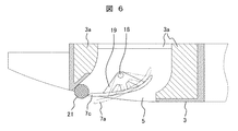
上記課題を解決する本実施例の空気調和機の室内機の構成を、図5及び図6を用いて説明する。図5は図1,図2に示す吹出口の1つの要部断面図で、本実施例1におけるルーバの第3角度について説明する図、図6は図5に示すルーバが第3角度の状態での作用を説明する図である。 The configuration of the indoor unit of the air conditioner of the present embodiment that solves the above problem will be described with reference to FIGS. FIG. 5 is a cross-sectional view of one main part of the air outlet shown in FIGS. 1 and 2, illustrating a third angle of the louver in the first embodiment. FIG. 6 is a state in which the louver shown in FIG. FIG.
図5において、一点鎖線で示すルーバ7の位置7aは、前記ルーバ7が最小角度(第1角度)の位置に設定されている場合を示し、同じく一点鎖線で示すルーバ7の位置7bは、前記ルーバ7が最大角度(第2角度)の位置に設定されている場合を示している。これらのルーバ7の位置7a,7bはリモコン(図示せず)から設定可能なルーバ7の角度であり、従来の室内機に一般的に具備されている機能である。また、前記ルーバ7は前記第1の角度位置7aから前記第2の角度位置の範囲でオートスイングする機能も一般的に備えられており、リモコンから設定可能である。
In FIG. 5, the
本実施例は、図1に示す4つの吹出口5におけるそれぞれのルーバ7の角度を、図5に示すように、図3に示す室内機停止時のルーバ角度である全閉角度(ルーバ角度0度)よりも大きく且つリモコンから設定可能な前記ルーバ7の最小開度である第1角度よりも小さい第3角度の位置7cに設定できるように構成されているものである。
In the present embodiment, as shown in FIG. 5, the angle of each
前記ルーバ7の第3角度の位置7cは、ユーザがリモコンから設定できる角度ではなく、暖房運転の運転開始時など、予め定めた所定の運転条件の場合に、空気調和機の室内機1等に備えられている制御装置から自動的に設定されるルーバ7の角度位置である。
例えば前記第1の角度が28度である場合、前記第3角度は、室内機停止時の全閉角度である0度よりも大きく、ユーザがリモコンから設定できる最小角度である前記第1角度(28度)よりも小さい角度、例えば14度などに設定される。前記第3角度は、14度には限られず、5〜25度の範囲で任意に設定すると良い。The
For example, when the first angle is 28 degrees, the third angle is larger than 0 degrees, which is the fully closed angle when the indoor unit is stopped, and is the first angle (the minimum angle that can be set by the user from the remote controller). 28 degrees), for example, 14 degrees. The third angle is not limited to 14 degrees and may be arbitrarily set in the range of 5 to 25 degrees.
即ち、本実施例は、リモコンから設定可能なルーバ7の角度である最小角度(第1角度)を1段目とし、最大角度(第2角度)を7段目とした場合、前記第3角度は0.5段目の角度に相当し、この0.5段目の角度は、ユーザがリモコンから設定可能なルーバ角度ではなく、室外機1等に設けられている制御装置から、所定の運転条件の場合に自動的に設定される角度である。
That is, in the present embodiment, when the minimum angle (first angle), which is the angle of the
本実施例では、上述したように、各ルーバ7を前記第3角度(0.5段目の角度)の位置7cに設定できるように構成されており、空気調和機が予め定めた所定の運転条件の場合に、複数の吹出口5のルーバ7のうち、一部の吹出口5のルーバ7が前記第3角度の位置7cに設定されるものである。
In the present embodiment, as described above, each
一部の吹出口5のルーバ7が前記第3角度(ルーバの全閉角度より大きく第1角度よりも小さい角度)の位置に設定されることにより、図6にハッチングの円で示すように、吹出口5の壁面とルーバ7の端部との間に小さい隙間21を形成することができる。従って、この隙間21から気流を吹き出させることができるので、風圧によるルーバのたわみを低減できる。従って、ルーバ7のたわみを小さく抑えることができるので、高温の空気を室内に吹き出す場合であってもルーバが塑性変形するのを抑制することができる。
When the
なお、前記第3角度に設定される前記ルーバ7は、所定時間毎に順次切り替えられるように構成すると良い。また、他の吹出口5のルーバ7は前記リモコンから設定可能なルーバ動作が為される。即ち、他のルーバ7はオートスイングに設定されたり、或いは任意のルーバ角度に設定される。
The
空気調和機の予め定めた前記所定の運転条件とは、例えば次のよう運転条件であり、次のような運転が為される場合に、複数の吹出口のルーバの内の一部の吹出口のルーバが、例えば室内機1に備えられている制御装置(図示せず)から自動的に前記第3角度に設定されるように構成すると良い。
(1)暖房運転が設定された場合。
(2)暖房運転時や冷房運転時に、外気温度と室温との温度差が予め定めた所定の温度差以上に大きい高負荷運転条件で運転される場合。
(3)暖房運転時や冷房運転時に、吹出し空気を床面付近など通常より遠くまで到達させる高速吹出し設定が為された場合。
(4)暖房運転時等に吹出し風速を大きくして、室内の上部と下部の温度差を小さくする攪拌運転が設定された場合、或いは空気調和機の制御装置が自動的に攪拌運転を実行する場合。The predetermined operating conditions predetermined for the air conditioner are, for example, the following operating conditions, and when the following operation is performed, some of the louvers of the plurality of outlets It is preferable that the louver is automatically set to the third angle by a control device (not shown) provided in the
(1) When the heating operation is set.
(2) A case where the system is operated under a high load operation condition in which the temperature difference between the outside air temperature and the room temperature is larger than a predetermined temperature difference during the heating operation or the cooling operation.
(3) When a high-speed blowing setting is made so that the blowing air reaches farther than usual, such as near the floor, during a heating operation or a cooling operation.
(4) When a stirring operation is set to increase the blowing air velocity during a heating operation to reduce the temperature difference between the upper part and the lower part of the room, or the control device of the air conditioner automatically executes the stirring operation. Case.
なお、前記第3角度は、前述したように、ユーザが、リモコンから任意のルーバを、前記第3角度に設定することができるものではなく、高速吹出し設定などが為された場合に、空気調和機の制御装置から自動的に設定される角度である。例えば、上述した(1)(3)(4)の何れかの運転が設定されたり、或いは上記(2)の条件で運転される場合や上記(4)の攪拌運転が自動的に実行される場合に、前記制御装置から自動的に、何れかの吹出口5のルーバ7の角度が第3角度位置に設定される。
Note that, as described above, the third angle is not one that allows the user to set an arbitrary louver to the third angle from a remote controller. The angle is automatically set from the control device of the machine. For example, any one of the above-described operations (1), (3), and (4) is set, or the operation is performed under the condition (2), or the stirring operation (4) is automatically performed. In this case, the angle of the
このように構成することにより、前記第3角度に設定されたルーバ部分の吹出口5の開口面積は小さくなるから、その吹出口5から吹き出される風量は大幅に低減され、他の吹出口5からの吹出し風速を十分に増加できる。従って、吹出し空気を床面など十分遠くの位置まで到達させることが可能となる。
With this configuration, the opening area of the
また、前記第3角度に設定されたルーバ部分の吹出口5では、該吹出口5の壁面と前記ルーバ7の端部との間に前述した小さい隙間21を形成することができ、この隙間21から気流を吹き出させることができるので、風圧によるルーバ7のたわみを低減できる。従って、遠心ファン9の回転数を増加させ、多量の高温空気を室内に吹き出す場合であっても、ルーバ7のたわみを低減できるから、ルーバ7が塑性変形するのも抑制することができる。
In the
なお、上述した実施例では、予め定めた所定の運転条件になると、複数の前記吹出口の内、一部の吹出口のルーバの角度を、前記第3角度に設定する構成としているが、この構成に代えて次のように構成しても良い。
即ち、前記所定の運転条件になった場合、複数の吹出口5の内の一部の吹出口のルーバ7の角度を、すぐに前記第3角度に制御するのではなく、まずルーバ7が塑性変形を起こさない程度の所定時間だけ、まず全閉角度に保持し、その後、前記所定時間経過後に前記ルーバ7を前記第3角度に制御するようにしても良い。In the above-described embodiment, when a predetermined operating condition is established, the angle of the louver of some of the plurality of outlets is set to the third angle. The following configuration may be used instead of the configuration.
That is, when the predetermined operating condition is satisfied, the angle of the
このように構成することにより、前記ルーバ7が全閉角度に保持されている時には、前記第3角度に制御された場合よりも、他の吹出口5からの吹出風速を更に大きくできるから、高速吹出しの効果を更に向上できる。しかも、全閉角度に制御された前記ルーバ7が塑性変形を起こす前に該ルーバ7を前記第3角度に制御するので、ルーバ7の塑性変形も防止できる効果が得られる。
With this configuration, when the
また、上述した実施例では、リモコンで設定可能な最小角度を第1角度とし、室内機停止時のルーバ角度である全閉角度よりも大きく且つ前記第1角度よりも小さいルーバ角度を第3角度としたが、これに代えて、以下のように構成しても良い。
即ち、ルーバをオートスイングさせる機能を有するものでは、オートスイング時のルーバの最小角度を第1角度とし、室内機停止時のルーバ角度である全閉角度よりも大きく且つ前記第1角度よりも小さいルーバ角度を第3角度に設定しても良い。この場合、第3角度に設定されたルーバ以外のルーバを備える他の吹出口5のルーバはオートスイング或いは任意の角度に設定される。In the above-described embodiment, the minimum angle that can be set by the remote controller is the first angle, and the louver angle that is larger than the fully closed angle that is the louver angle when the indoor unit is stopped and smaller than the first angle is the third angle. However, the following configuration may be used instead.
That is, in a device having a function of automatically swinging the louver, the minimum angle of the louver during the automatic swing is set to the first angle, which is larger than the fully closed angle which is the louver angle when the indoor unit is stopped, and smaller than the first angle. The louver angle may be set to the third angle. In this case, the louvers of the
以上説明したように、本実施例では、高速吹出し設定などが為された場合など、予め定めた所定の運転条件では、複数の前記吹出口5の内、一部の吹出口のルーバ7の角度を、室内機停止時のルーバ角度である全閉角度(0度)よりも大きく且つリモコンで設定可能な或いはオートスイング時の最小角度である第1角度よりも小さい第3角度に設定され、他の吹出口のルーバ7はリモコンから設定可能なルーバ動作を行うように構成しているので、複数の吹出口5の一部の吹出口からの高速吹出しを可能にしつつ、各吹出口5に設けられているルーバ7のたわみを抑制することもできる空気調和機の室内機を得ることができる効果がある。
As described above, in the present embodiment, the angle of the
なお、本発明は上述した実施例に限定されるものではなく、様々な変形例が含まれる。また、上記した実施例は本発明を分かりやすく説明するために詳細に説明したものであり、必ずしも説明した全ての構成を備えるものに限定されるものではない。 Note that the present invention is not limited to the above-described embodiments, and includes various modifications. Further, the above-described embodiments have been described in detail for easy understanding of the present invention, and are not necessarily limited to those having all the configurations described above.
1:室内機、2:筐体、3:化粧パネル、3a:断熱材、4:吸込口、5:吹出口、6:吸込グリル、7:ルーバ、7a:最小角度(第1角度)の位置、7b:最大角度(第2角度)の位置、8:モータ、9:遠心ファン、10:熱交換器、11:ドレンパン、12:吸込部、13:吐出部、14:風路、15:ベルマウス、16:電気品箱、17:吸込フィルタ、18:中心軸、19:取付部材、20:天井、21:隙間。 1: indoor unit, 2: housing, 3: decorative panel, 3a: heat insulating material, 4: inlet, 5: outlet, 6: inlet grill, 7: louver, 7a: minimum angle (first angle) position , 7b: maximum angle (second angle) position, 8: motor, 9: centrifugal fan, 10: heat exchanger, 11: drain pan, 12: suction unit, 13: discharge unit, 14: air path, 15: bell Mouse, 16: electrical component box, 17: suction filter, 18: central axis, 19: mounting member, 20: ceiling, 21: gap.
Claims (10)
室内機の停止時には前記ルーバは前記吹出口を閉じる方向に回動されると共に、前記吹出口を閉じる方向に回動された室内機停止時のルーバ角度を全閉角度とし、
前記室内機の運転時に前記ルーバの動作を設定するためのリモコンを備え、前記リモコンで設定可能な前記ルーバの角度のうちの最小角度を第1角度とし、最大角度を第2角度としたとき、
予め定めた所定の運転条件では、複数の前記吹出口の内、一部の吹出口のルーバ角度を、室内機停止時のルーバ角度である全閉角度よりも大きく且つ前記第1角度よりも小さい第3角度に設定され、他の前記吹出口のルーバは前記リモコンから設定可能なルーバ動作を行うことを特徴とする空気調和機の室内機。In an indoor unit of an air conditioner including a plurality of outlets and a plurality of louvers provided in each of the outlets and configured to be capable of adjusting a blowing direction,
When the indoor unit is stopped, the louver is rotated in the direction to close the air outlet, and the louver angle when the indoor unit is turned in the direction to close the air outlet is a fully closed angle,
When a remote control for setting the operation of the louver during operation of the indoor unit is provided, when the minimum angle among the louver angles that can be set with the remote control is the first angle and the maximum angle is the second angle,
Under predetermined operating conditions, the louver angles of some of the plurality of outlets are larger than the fully closed angle, which is the louver angle when the indoor unit is stopped, and smaller than the first angle. The indoor unit for an air conditioner, wherein the louver of the outlet is set to a third angle and performs a louver operation that can be set from the remote controller.
前記所定の運転条件になると、複数の前記ルーバの内の一部のルーバの角度を、所定時間全閉角度に保持し、その後、前記第3角度に制御されることを特徴とする空気調和機の室内機。The indoor unit of the air conditioner according to claim 1,
The air conditioner is characterized in that when the predetermined operating condition is reached, the angle of a part of the plurality of louvers is maintained at a fully closed angle for a predetermined time, and then controlled to the third angle. Indoor unit.
室内機停止時のルーバ角度である全閉角度を0度としたとき、前記第1角度は27〜30度の範囲で、前記第2角度は60〜70度の範囲で、それぞれ任意に設定され、更に前記第3角度は5〜25度の範囲で任意に設定されていることを特徴とする空気調和機の室内機。The indoor unit of the air conditioner according to claim 1,
When the fully closed angle, which is the louver angle when the indoor unit is stopped, is 0 degree, the first angle is arbitrarily set in a range of 27 to 30 degrees, and the second angle is arbitrarily set in a range of 60 to 70 degrees. The indoor unit of an air conditioner, wherein the third angle is arbitrarily set within a range of 5 to 25 degrees.
前記吹出口は、前記室内機の中央の吸込口を囲むように4か所設けられ、前記第3角度に設定されるルーバは所定時間毎に順次切り替えられるように構成されていることを特徴とする空気調和機の室内機。The indoor unit of the air conditioner according to claim 1,
The air outlet is provided at four locations so as to surround a central air inlet of the indoor unit, and the louver set at the third angle is configured to be sequentially switched at predetermined time intervals. Air conditioner indoor unit.
前記所定の運転条件は暖房運転であることを特徴とする空気調和機の室内機。The indoor unit of the air conditioner according to claim 1,
The indoor unit for an air conditioner, wherein the predetermined operation condition is a heating operation.
前記所定の運転条件は、外気温度と室温との温度差が予め定めた所定の温度差以上に大きい高負荷運転条件で運転される場合であることを特徴とする空気調和機の室内機。The indoor unit of the air conditioner according to claim 1,
The indoor unit of an air conditioner, wherein the predetermined operation condition is a case where the air conditioner is operated under a high load operation condition in which a temperature difference between an outside air temperature and a room temperature is larger than a predetermined temperature difference.
前記所定の運転条件は高速吹出しが設定された場合であることを特徴とする空気調和機の室内機。The indoor unit of the air conditioner according to claim 1,
The indoor unit of an air conditioner, wherein the predetermined operating condition is a case where high-speed blowing is set.
前記所定の運転条件は、吹出し風速を大きくして、室内の上部と下部の温度差を小さくする攪拌運転を行う場合であることを特徴とする空気調和機の室内機。The indoor unit of the air conditioner according to claim 1,
The indoor unit of an air conditioner, wherein the predetermined operating condition is a case where a stirring operation is performed to increase a blowing wind speed and reduce a temperature difference between an upper portion and a lower portion in a room.
室内機の停止時には前記ルーバは前記吹出口を閉じる方向に回動されると共に、前記吹出口を閉じる方向に回動された室内機停止時のルーバ角度を全閉角度とし、
前記室内機の運転時に前記ルーバをオートスイングさせる機能を有し、前記オートスイング時の前記ルーバの最小角度を第1角度とし、最大角度を第2角度としたとき、
予め定めた所定の運転条件では、複数の前記吹出口の内、一部の吹出口のルーバ角度を、室内機停止時のルーバ角度である全閉角度よりも大きく且つ前記第1角度よりも小さい第3角度に設定され、他の前記吹出口のルーバはオートスイング或いは任意の角度に設定されることを特徴とする空気調和機の室内機。In an indoor unit of an air conditioner including a plurality of outlets, and a plurality of louvers provided in each of the outlets and configured to be capable of adjusting a blowing direction,
When the indoor unit is stopped, the louver is rotated in the direction to close the air outlet, and the louver angle when the indoor unit is turned in the direction to close the air outlet is a fully closed angle,
When the indoor unit has a function of automatically swinging the louver during operation, when the minimum angle of the louver during the automatic swing is a first angle, and the maximum angle is a second angle,
Under predetermined operating conditions, the louver angles of some of the plurality of outlets are larger than the fully closed angle, which is the louver angle when the indoor unit is stopped, and smaller than the first angle. The indoor unit for an air conditioner, wherein the third angle is set, and the louvers of the other outlets are set to an automatic swing or an arbitrary angle.
前記室内機の運転時に前記ルーバの動作を設定するためのリモコンを備え、前記第1角度は前記リモコンで設定可能な前記ルーバの角度のうちの最小角度であることを特徴とする空気調和機の室内機。The indoor unit of the air conditioner according to claim 9,
An air conditioner, comprising: a remote controller for setting an operation of the louver during operation of the indoor unit, wherein the first angle is a minimum angle of the louver angle settable by the remote controller. Indoor unit.
Applications Claiming Priority (1)
| Application Number | Priority Date | Filing Date | Title |
|---|---|---|---|
| PCT/JP2017/043574 WO2019111308A1 (en) | 2017-12-05 | 2017-12-05 | Indoor unit for air conditioner |
Publications (2)
| Publication Number | Publication Date |
|---|---|
| JPWO2019111308A1 JPWO2019111308A1 (en) | 2019-12-12 |
| JP6668552B2 true JP6668552B2 (en) | 2020-03-18 |
Family
ID=66751333
Family Applications (1)
| Application Number | Title | Priority Date | Filing Date |
|---|---|---|---|
| JP2019503366A Active JP6668552B2 (en) | 2017-12-05 | 2017-12-05 | Air conditioner indoor unit |
Country Status (6)
| Country | Link |
|---|---|
| US (1) | US20200224889A1 (en) |
| EP (1) | EP3722692A4 (en) |
| JP (1) | JP6668552B2 (en) |
| KR (1) | KR102135622B1 (en) |
| CN (1) | CN110121621B (en) |
| WO (1) | WO2019111308A1 (en) |
Families Citing this family (4)
| Publication number | Priority date | Publication date | Assignee | Title |
|---|---|---|---|---|
| EP3842703A4 (en) * | 2018-08-21 | 2022-03-30 | Hitachi-Johnson Controls Air Conditioning, Inc. | Indoor unit for air conditioner |
| JPWO2020090641A1 (en) * | 2018-11-02 | 2021-09-16 | パナソニックIpマネジメント株式会社 | Environmental control system and environmental control method |
| CN113188185A (en) * | 2020-01-14 | 2021-07-30 | 青岛海尔空调电子有限公司 | Air deflector control method for air conditioner and air conditioner |
| US12292204B2 (en) * | 2021-12-23 | 2025-05-06 | Samsung Electronics Co., Ltd. | Air conditioner |
Family Cites Families (23)
| Publication number | Priority date | Publication date | Assignee | Title |
|---|---|---|---|---|
| CH584872A5 (en) * | 1974-10-22 | 1977-02-15 | Luwa Ag | |
| DE2948335A1 (en) | 1979-11-30 | 1981-06-04 | Siemens AG, 1000 Berlin und 8000 München | CIRCUIT ARRANGEMENT FOR THE REMOTE POWERING OF INTERMEDIARIES OF A DEVICE FOR THE MESSAGE TRANSMISSION TECHNOLOGY BY MEANS OF DC SERIES POWERING |
| JP2001116324A (en) * | 1999-10-12 | 2001-04-27 | Matsushita Refrig Co Ltd | Air conditioner |
| JP2001174043A (en) * | 1999-12-20 | 2001-06-29 | Fujitsu General Ltd | Ceiling-mounted air conditioner |
| JP2007024453A (en) * | 2005-07-21 | 2007-02-01 | Mitsubishi Electric Corp | Air conditioner |
| CN2861849Y (en) * | 2005-12-27 | 2007-01-24 | 上海日立家用电器有限公司 | Air conditioner capable of adjusting wind deflection and controlling in section |
| JP4580377B2 (en) * | 2006-11-22 | 2010-11-10 | シャープ株式会社 | Air conditioner |
| AU2010299201B2 (en) * | 2009-09-28 | 2013-07-25 | Daikin Industries, Ltd. | Control device |
| JP5304574B2 (en) * | 2009-09-28 | 2013-10-02 | ダイキン工業株式会社 | Control device |
| JP2011069592A (en) * | 2009-09-28 | 2011-04-07 | Daikin Industries Ltd | Control device |
| AU2011211125B2 (en) * | 2010-01-26 | 2013-09-19 | Daikin Industries, Ltd. | Ceiling-mounted indoor unit for air conditioning apparatus |
| JP5518013B2 (en) * | 2011-08-18 | 2014-06-11 | 三菱電機株式会社 | Air conditioner indoor unit and air conditioner equipped with the indoor unit |
| JP5267628B2 (en) * | 2011-08-31 | 2013-08-21 | ダイキン工業株式会社 | Air conditioning indoor unit |
| JP5692327B1 (en) * | 2013-09-30 | 2015-04-01 | ダイキン工業株式会社 | Air conditioner |
| JP6138062B2 (en) * | 2014-01-16 | 2017-05-31 | 三菱電機株式会社 | Air conditioner |
| JP6444224B2 (en) * | 2015-03-06 | 2018-12-26 | 日立ジョンソンコントロールズ空調株式会社 | Air conditioner indoor unit |
| JP2016183806A (en) * | 2015-03-26 | 2016-10-20 | ダイキン工業株式会社 | Air conditioner |
| JP6570916B2 (en) * | 2015-08-13 | 2019-09-04 | 三菱重工サーマルシステムズ株式会社 | Indoor unit, air conditioner equipped with the same, control method for indoor unit, and control program |
| JP6229741B2 (en) * | 2015-09-29 | 2017-11-15 | ダイキン工業株式会社 | Indoor unit of air conditioner |
| JP6135734B2 (en) * | 2015-09-29 | 2017-05-31 | ダイキン工業株式会社 | Indoor unit of air conditioner |
| WO2017208404A1 (en) * | 2016-06-01 | 2017-12-07 | 三菱電機株式会社 | Air conditioner |
| CN106403227B (en) * | 2016-08-30 | 2020-06-05 | 芜湖美智空调设备有限公司 | Air-conditioning wind deflector and air conditioner having the same |
| CN206626675U (en) * | 2017-03-17 | 2017-11-10 | 广东美的制冷设备有限公司 | For the air deflection assemblies of indoor apparatus of air conditioner, indoor apparatus of air conditioner and air conditioner |
-
2017
- 2017-12-05 CN CN201780044176.9A patent/CN110121621B/en active Active
- 2017-12-05 KR KR1020197004822A patent/KR102135622B1/en active Active
- 2017-12-05 JP JP2019503366A patent/JP6668552B2/en active Active
- 2017-12-05 US US16/321,599 patent/US20200224889A1/en not_active Abandoned
- 2017-12-05 EP EP17918690.3A patent/EP3722692A4/en not_active Withdrawn
- 2017-12-05 WO PCT/JP2017/043574 patent/WO2019111308A1/en not_active Ceased
Also Published As
| Publication number | Publication date |
|---|---|
| KR102135622B1 (en) | 2020-07-20 |
| US20200224889A1 (en) | 2020-07-16 |
| CN110121621A (en) | 2019-08-13 |
| EP3722692A4 (en) | 2021-11-03 |
| CN110121621B (en) | 2021-04-27 |
| EP3722692A1 (en) | 2020-10-14 |
| WO2019111308A1 (en) | 2019-06-13 |
| KR20190076947A (en) | 2019-07-02 |
| JPWO2019111308A1 (en) | 2019-12-12 |
Similar Documents
| Publication | Publication Date | Title |
|---|---|---|
| WO2021036405A1 (en) | Indoor unit, air conditioner, and air conditioner control method | |
| JP6668552B2 (en) | Air conditioner indoor unit | |
| CN108474581B (en) | Air Conditioning System | |
| JP2004012060A (en) | Indoor unit for air conditioner and air conditioner | |
| CN111919064A (en) | Indoor unit of air conditioner | |
| JP2007198641A (en) | Floor-mounted air conditioning indoor unit | |
| JP6690256B2 (en) | Ceiling embedded air conditioner | |
| JP4749352B2 (en) | Air conditioner | |
| CN108474582B (en) | Air conditioning system | |
| KR20190078003A (en) | Stand type air conditioner | |
| JP2007205584A (en) | Air conditioner | |
| JP2000111131A (en) | Air outlet structure of blower | |
| US10724759B2 (en) | Indoor unit for air-conditioning apparatus | |
| JP7033392B2 (en) | Indoor unit of air conditioner and air conditioner | |
| JP7436842B2 (en) | floor-standing air conditioner | |
| JP6609722B1 (en) | Air conditioner indoor unit | |
| CN111902679A (en) | Indoor unit of air conditioner | |
| CN118998832A (en) | Control method of air conditioner | |
| WO2017209078A1 (en) | Air conditioner | |
| JPH0639973B2 (en) | Ceiling-mounted air conditioner | |
| WO2022064768A1 (en) | Floor-standing air conditioner | |
| JP2017110879A (en) | Indoor unit | |
| JP2016099034A (en) | Air conditioning device, adjustment method of air conditioning device and manufacturing method of air conditioning facility | |
| CN119573217B (en) | Air conditioner and control method thereof | |
| CN106468472A (en) | Air conditioner |
Legal Events
| Date | Code | Title | Description |
|---|---|---|---|
| A621 | Written request for application examination |
Free format text: JAPANESE INTERMEDIATE CODE: A621 Effective date: 20190121 |
|
| TRDD | Decision of grant or rejection written | ||
| A01 | Written decision to grant a patent or to grant a registration (utility model) |
Free format text: JAPANESE INTERMEDIATE CODE: A01 Effective date: 20200128 |
|
| A61 | First payment of annual fees (during grant procedure) |
Free format text: JAPANESE INTERMEDIATE CODE: A61 Effective date: 20200226 |
|
| R150 | Certificate of patent or registration of utility model |
Ref document number: 6668552 Country of ref document: JP Free format text: JAPANESE INTERMEDIATE CODE: R150 |