JP6668138B2 - earphone - Google Patents
earphone Download PDFInfo
- Publication number
- JP6668138B2 JP6668138B2 JP2016064814A JP2016064814A JP6668138B2 JP 6668138 B2 JP6668138 B2 JP 6668138B2 JP 2016064814 A JP2016064814 A JP 2016064814A JP 2016064814 A JP2016064814 A JP 2016064814A JP 6668138 B2 JP6668138 B2 JP 6668138B2
- Authority
- JP
- Japan
- Prior art keywords
- earphone
- housing
- diaphragm
- sound
- space
- Prior art date
- Legal status (The legal status is an assumption and is not a legal conclusion. Google has not performed a legal analysis and makes no representation as to the accuracy of the status listed.)
- Active
Links
- 230000007246 mechanism Effects 0.000 claims description 21
- 238000004891 communication Methods 0.000 claims description 12
- 239000003990 capacitor Substances 0.000 claims description 6
- 229920005989 resin Polymers 0.000 claims description 2
- 239000011347 resin Substances 0.000 claims description 2
- 239000000463 material Substances 0.000 description 41
- 230000002093 peripheral effect Effects 0.000 description 23
- 230000001681 protective effect Effects 0.000 description 21
- 239000012212 insulator Substances 0.000 description 20
- 125000006850 spacer group Chemical group 0.000 description 19
- 229910052751 metal Inorganic materials 0.000 description 11
- 239000002184 metal Substances 0.000 description 11
- 230000005236 sound signal Effects 0.000 description 9
- 210000000613 ear canal Anatomy 0.000 description 8
- 239000010408 film Substances 0.000 description 8
- 229920003002 synthetic resin Polymers 0.000 description 7
- 239000000057 synthetic resin Substances 0.000 description 7
- 210000003454 tympanic membrane Anatomy 0.000 description 7
- 238000010586 diagram Methods 0.000 description 6
- 102100036791 Adhesion G protein-coupled receptor L2 Human genes 0.000 description 4
- 101000928189 Homo sapiens Adhesion G protein-coupled receptor L2 Proteins 0.000 description 4
- 229910001369 Brass Inorganic materials 0.000 description 3
- 229910052782 aluminium Inorganic materials 0.000 description 3
- XAGFODPZIPBFFR-UHFFFAOYSA-N aluminium Chemical compound [Al] XAGFODPZIPBFFR-UHFFFAOYSA-N 0.000 description 3
- 239000010951 brass Substances 0.000 description 3
- 229910000881 Cu alloy Inorganic materials 0.000 description 2
- 239000004734 Polyphenylene sulfide Substances 0.000 description 2
- 230000008901 benefit Effects 0.000 description 2
- 230000008859 change Effects 0.000 description 2
- 210000003027 ear inner Anatomy 0.000 description 2
- 210000003128 head Anatomy 0.000 description 2
- 238000003780 insertion Methods 0.000 description 2
- 230000037431 insertion Effects 0.000 description 2
- 239000004033 plastic Substances 0.000 description 2
- 229920003023 plastic Polymers 0.000 description 2
- 239000004417 polycarbonate Substances 0.000 description 2
- 229920000139 polyethylene terephthalate Polymers 0.000 description 2
- 239000005020 polyethylene terephthalate Substances 0.000 description 2
- 229920000069 polyphenylene sulfide Polymers 0.000 description 2
- 239000005871 repellent Substances 0.000 description 2
- 239000000565 sealant Substances 0.000 description 2
- 229920002379 silicone rubber Polymers 0.000 description 2
- 125000002066 L-histidyl group Chemical group [H]N1C([H])=NC(C([H])([H])[C@](C(=O)[*])([H])N([H])[H])=C1[H] 0.000 description 1
- 238000005452 bending Methods 0.000 description 1
- 238000006243 chemical reaction Methods 0.000 description 1
- 230000000295 complement effect Effects 0.000 description 1
- 229920001577 copolymer Polymers 0.000 description 1
- 239000013013 elastic material Substances 0.000 description 1
- 229920001971 elastomer Polymers 0.000 description 1
- 239000000835 fiber Substances 0.000 description 1
- PCHJSUWPFVWCPO-UHFFFAOYSA-N gold Chemical compound [Au] PCHJSUWPFVWCPO-UHFFFAOYSA-N 0.000 description 1
- 239000010931 gold Substances 0.000 description 1
- 229910052737 gold Inorganic materials 0.000 description 1
- HCDGVLDPFQMKDK-UHFFFAOYSA-N hexafluoropropylene Chemical group FC(F)=C(F)C(F)(F)F HCDGVLDPFQMKDK-UHFFFAOYSA-N 0.000 description 1
- 238000000034 method Methods 0.000 description 1
- 229920000515 polycarbonate Polymers 0.000 description 1
- -1 polyethylene terephthalate Polymers 0.000 description 1
- 230000004044 response Effects 0.000 description 1
- 239000003566 sealing material Substances 0.000 description 1
- 210000004243 sweat Anatomy 0.000 description 1
- BFKJFAAPBSQJPD-UHFFFAOYSA-N tetrafluoroethene Chemical group FC(F)=C(F)F BFKJFAAPBSQJPD-UHFFFAOYSA-N 0.000 description 1
- 239000010409 thin film Substances 0.000 description 1
Images


Classifications
-
- H—ELECTRICITY
- H04—ELECTRIC COMMUNICATION TECHNIQUE
- H04R—LOUDSPEAKERS, MICROPHONES, GRAMOPHONE PICK-UPS OR LIKE ACOUSTIC ELECTROMECHANICAL TRANSDUCERS; DEAF-AID SETS; PUBLIC ADDRESS SYSTEMS
- H04R1/00—Details of transducers, loudspeakers or microphones
- H04R1/10—Earpieces; Attachments therefor ; Earphones; Monophonic headphones
- H04R1/1016—Earpieces of the intra-aural type
-
- H—ELECTRICITY
- H04—ELECTRIC COMMUNICATION TECHNIQUE
- H04R—LOUDSPEAKERS, MICROPHONES, GRAMOPHONE PICK-UPS OR LIKE ACOUSTIC ELECTROMECHANICAL TRANSDUCERS; DEAF-AID SETS; PUBLIC ADDRESS SYSTEMS
- H04R1/00—Details of transducers, loudspeakers or microphones
- H04R1/10—Earpieces; Attachments therefor ; Earphones; Monophonic headphones
- H04R1/1041—Mechanical or electronic switches, or control elements
-
- H—ELECTRICITY
- H04—ELECTRIC COMMUNICATION TECHNIQUE
- H04R—LOUDSPEAKERS, MICROPHONES, GRAMOPHONE PICK-UPS OR LIKE ACOUSTIC ELECTROMECHANICAL TRANSDUCERS; DEAF-AID SETS; PUBLIC ADDRESS SYSTEMS
- H04R1/00—Details of transducers, loudspeakers or microphones
- H04R1/10—Earpieces; Attachments therefor ; Earphones; Monophonic headphones
- H04R1/1058—Manufacture or assembly
- H04R1/1075—Mountings of transducers in earphones or headphones
-
- H—ELECTRICITY
- H04—ELECTRIC COMMUNICATION TECHNIQUE
- H04R—LOUDSPEAKERS, MICROPHONES, GRAMOPHONE PICK-UPS OR LIKE ACOUSTIC ELECTROMECHANICAL TRANSDUCERS; DEAF-AID SETS; PUBLIC ADDRESS SYSTEMS
- H04R1/00—Details of transducers, loudspeakers or microphones
- H04R1/02—Casings; Cabinets ; Supports therefor; Mountings therein
- H04R1/023—Screens for loudspeakers
-
- H—ELECTRICITY
- H04—ELECTRIC COMMUNICATION TECHNIQUE
- H04R—LOUDSPEAKERS, MICROPHONES, GRAMOPHONE PICK-UPS OR LIKE ACOUSTIC ELECTROMECHANICAL TRANSDUCERS; DEAF-AID SETS; PUBLIC ADDRESS SYSTEMS
- H04R1/00—Details of transducers, loudspeakers or microphones
- H04R1/20—Arrangements for obtaining desired frequency or directional characteristics
- H04R1/22—Arrangements for obtaining desired frequency or directional characteristics for obtaining desired frequency characteristic only
- H04R1/28—Transducer mountings or enclosures modified by provision of mechanical or acoustic impedances, e.g. resonator, damping means
- H04R1/2807—Enclosures comprising vibrating or resonating arrangements
- H04R1/2811—Enclosures comprising vibrating or resonating arrangements for loudspeaker transducers
Description
本発明は、イヤホンに関する。 The present invention relates to an earphone.
イヤホンやヘッドホンが備える電気音響変換器の中で、周波数応答に優れ、高忠実度再生(Hi-Fi再生)に適している電気音響変換器として、コンデンサ型の電気音響変換器がある。一般的にコンデンサ型の電気音響変換器には、高調波ひずみを抑制するために、プッシュプル方式が用いられる。コンデンサ型の電気音響変換器は、振動板と、振動板の両面に対向して配置される一対の固定極と、を備える。 Among the electro-acoustic transducers included in earphones and headphones, there is a capacitor-type electro-acoustic transducer as an electro-acoustic transducer having excellent frequency response and suitable for high-fidelity reproduction (Hi-Fi reproduction). Generally, a push-pull method is used for a capacitor-type electroacoustic transducer in order to suppress harmonic distortion. The capacitor-type electro-acoustic transducer includes a diaphragm and a pair of fixed poles disposed on both sides of the diaphragm.
コンデンサ型の電気音響変換器を用いたイヤホンとして、密閉型のイヤホン(例えば、特許文献1参照)と、開放型のイヤホン(例えば、非特許文献1参照)と、が提案されている。 As earphones using a capacitor-type electro-acoustic transducer, a closed earphone (for example, see Patent Literature 1) and an open earphone (for example, see Non-Patent Literature 1) have been proposed.
一般的に、密閉型のイヤホンは、音漏れが小さく、公共の場所やレコーディング現場などでの使用に適している。しかし、密閉型のイヤホンは、振動板の動きが制限され易く、音がこもり易い。 Generally, closed earphones have low sound leakage and are suitable for use in public places and recording sites. However, in the closed earphone, the movement of the diaphragm is easily limited, and the sound is easily muffled.
一方、開放型のイヤホンは、密閉型のイヤホンと比べて、聴感上、音がこもらず自然な音質を実現しやすいと言われている。そのため、開放型のイヤホンを好んで使用する使用者は多い。しかし、開放型のイヤホンは、音漏れが大きく、公共の場所やレコーディング現場などでの使用には適していない。 On the other hand, it is said that open earphones are easier to realize natural sound quality because of less audible sound than closed earphones. For this reason, many users prefer open earphones. However, open-type earphones have large sound leakage and are not suitable for use in public places and recording sites.
このように、密閉型のイヤホンと開放型のイヤホンとには、それぞれメリットとデメリットとがある。そのため、イヤホンの使用者(以下「使用者」という。)は、使用用途や趣向に応じて密閉型のイヤホンと開放型のイヤホンとのいずれかを適宜選択しなければならず、使用者の利便性が悪い。 As described above, the closed earphone and the open earphone have advantages and disadvantages, respectively. For this reason, the user of the earphone (hereinafter referred to as “user”) must appropriately select either the closed earphone or the open earphone according to the intended use or taste, which is convenient for the user. Poor.
また、コンデンサ型の電気音響変換器において、振動板の動作は、振動板の前後の空気のスチフネスによって制限される。すなわち、振動板の前後の空気の容積は、コンデンサ型の電気音響変換器の特性(例えば、周波数特性)に影響を与える。そのため、密閉型のコンデンサ型イヤホンと開放型のコンデンサ型イヤホンとには、それぞれに合せた音響的な設計が施されてきた。 Further, in the capacitor-type electroacoustic transducer, the operation of the diaphragm is limited by the stiffness of air before and after the diaphragm. That is, the volume of air before and after the diaphragm affects characteristics (for example, frequency characteristics) of the capacitor-type electroacoustic transducer. For this reason, the acoustic design corresponding to each of the closed-type condenser-type earphone and the open-type condenser-type earphone has been performed.
本発明は、以上のような従来技術の問題点を解消するためになされたもので、コンデンサ型の電気音響変換器を備える1台のイヤホンにおいて、密閉型のイヤホンの機能と、開放型のイヤホンの機能と、を切り換え可能にすると共に、いずれの機能を提供する状態においても音響的に良好なイヤホンを提供することを目的とする。 SUMMARY OF THE INVENTION The present invention has been made to solve the above-described problems of the related art. In one earphone including a capacitor-type electro-acoustic transducer, the function of a closed earphone and the function of an open earphone are described. It is another object of the present invention to provide an earphone which can be switched between the above-mentioned function and acoustically good in a state where any of the functions is provided.
本発明は、イヤホンであって、振動板と、振動板との間でコンデンサを構成する固定極と、振動板と固定極とを収納するハウジングと、ハウジングの前方に突設される音導管と、ハウジングの外部とハウジングの内部とを連通させる連通孔と、連通孔を開閉する開閉機構と、を有してなり、音導管の内部の空間の容積と、ハウジングの内部の空間のうち音導管の内部の空間と連通する振動板の前方の空間の容積と、の和は、ハウジングの内部の空間のうち振動板の後方の空間の容積よりも小さい、ことを特徴とする。 The present invention relates to an earphone, in which a diaphragm, a fixed pole forming a capacitor between the diaphragm, a housing accommodating the diaphragm and the fixed pole, and a sound conduit protruding forward of the housing. , a communication hole for communicating the interior of the exterior housing of the housing, it comprises a closing mechanism for opening and closing the communication hole, and a volume of the inner space of the sound guiding tube, of sound conduit internal space of the housing The sum of the volume of the space in front of the diaphragm communicating with the space inside the housing is smaller than the volume of the space behind the diaphragm in the space inside the housing.
本発明によれば、コンデンサ型の電気音響変換器を備える1台のイヤホンにおいて、密閉型のイヤホンの機能と、開放型のイヤホンの機能と、を切り換え可能にすると共に、いずれの機能を提供する状態においても音響的に良好なイヤホンを提供することができる。 ADVANTAGE OF THE INVENTION According to this invention, in one earphone provided with the electroacoustic transducer of a condenser type, the function of a closed-type earphone and the function of an open-type earphone can be switched, and any function is provided. Even in the state, it is possible to provide an acoustically good earphone.
●イヤホン●
以下、図面を参照しながら、本発明にかかるイヤホンの実施の形態について説明する。
● Earphone ●
Hereinafter, an embodiment of an earphone according to the present invention will be described with reference to the drawings.
●イヤホンの構成
図1は、本発明にかかるイヤホンの実施の形態を示す外観図である。
イヤホンEは、例えば、携帯型音楽再生機(不図示)などの音源からの音声信号に応じた音波をイヤホンEの使用者(以下「使用者」という。)の鼓膜に向けて出力する。イヤホンEは、左イヤホンユニット(以下「左ユニット」という。)LEと、右イヤホンユニット(以下「右ユニット」という。)REと、を備える。左ユニットLEと右ユニットREとは使用者の耳に装着される。イヤホンEは、後述するコンデンサ型の電気音響変換器を備えたコンデンサ型イヤホンである。
Configuration of Earphone FIG. 1 is an external view showing an embodiment of an earphone according to the present invention.
The earphone E outputs, for example, a sound wave corresponding to an audio signal from a sound source such as a portable music player (not shown) toward the eardrum of a user of the earphone E (hereinafter, referred to as “user”). The earphone E includes a left earphone unit (hereinafter, referred to as “left unit”) LE and a right earphone unit (hereinafter, referred to as “right unit”) RE. The left unit LE and the right unit RE are mounted on the user's ear. The earphone E is a condenser-type earphone provided with a condenser-type electroacoustic transducer described later.
左ユニットLEの構成と右ユニットREの構成とは、左右対称であるため、左ユニットLEの構成を例に、以下説明する。 Since the configuration of the left unit LE and the configuration of the right unit RE are bilaterally symmetric, the configuration of the left unit LE will be described below as an example.
図2は、左ユニットLEの図1におけるA矢視図である。
以下の説明において、左ユニットLEが使用者の左耳に装着された状態(以下「装着状態」という。)における使用者の頭部に面する側(図2の紙面下側)の方向を前方という。使用者の頭頂部側(図2の紙面奥側)の方向を上方という。使用者の正面側(図2の紙面左側)の方向を左方という。
FIG. 2 is a view of the left unit LE as viewed from an arrow A in FIG.
In the following description, the direction of the side facing the user's head (the lower side of the paper surface of FIG. 2) in a state where the left unit LE is mounted on the left ear of the user (hereinafter referred to as a “mounting state”) is defined as a forward direction. That. The direction toward the top of the user's head (the back side in FIG. 2) is referred to as upward. The direction of the front side of the user (left side in FIG. 2) is referred to as left.
左ユニットLEは、使用者の左耳に装着されて、使用者の左耳の鼓膜に向けて音源からの音声信号に応じた音波を出力する。左ユニットLEは、左ユニット本体(以下「本体」という。)LEBと、開閉機構である左ユニットカバー部材(以下「カバー部材」という。)LECと、を備える。 The left unit LE is attached to the left ear of the user, and outputs a sound wave corresponding to the audio signal from the sound source toward the eardrum of the left ear of the user. The left unit LE includes a left unit main body (hereinafter, referred to as “main body”) LEB and a left unit cover member (hereinafter, referred to as “cover member”) LEC that is an opening / closing mechanism.
図3は、左ユニットLEの分解図である。
図4は、本体LEBの図3におけるC矢視図である。
図5は、左ユニットLEの図2におけるBB線断面図である。
FIG. 3 is an exploded view of the left unit LE.
FIG. 4 is a view of the main body LEB as viewed in the direction of arrow C in FIG.
FIG. 5 is a cross-sectional view of the left unit LE taken along line BB in FIG.
本体LEBは、ハウジング1とハンガー2と音導管3とイヤピース4と電気音響変換器5と固定部材6と防護材7とコードブッシュ8とコード9とを備える。
The main body LEB includes a
ハウジング1は、電気音響変換器5を収納する。ハウジング1の材料は、例えば、アルミニウムなどの金属である。ハウジング1は、図5に示すように、前部ハウジング半体10と後部ハウジング半体11とシール材12とを備える。前部ハウジング半体10と後部ハウジング半体11とはねじ(不図示)により締結される。ハウジング1の形状は、前後方向(図5の上下方向)に扁平な略矩形の箱状である。すなわち、ハウジング1は、前壁10aと後壁11aと周壁とを備える中空体である。
The
なお、ハウジング1の材料は、電気音響変換器5が発生させる音波によりハウジング1自体が振動しない程度の剛性を備えていれば、金属に限定されない。すなわち、例えば、ハウジング1の材料は、プラスチックなどの合成樹脂でもよい。
The material of the
ハウジング1は、内壁10bを備える。内壁10bは、ハウジング1の後壁11aに向かって突出する。内壁10bは、前壁10aの後面を矩形状に囲う(図8参照)。
The
前壁10aは、矩形の凹部10cと、円形の嵌合凹部10dと、円形の前部放音孔10hと、を備える。凹部10cは、内壁10bに囲われた前壁10aの内面のうち、周縁部を除いた領域に配置される。嵌合凹部10dは、前壁10aの外面のうち、凹部10cと背中合わせとなる領域の下半部に配置される。前部放音孔10hは、電気音響変換器5からの音波を音導管3へ導く。前部放音孔10hは、嵌合凹部10dの中央に配置される。
The front wall 10a includes a rectangular
後壁11aは、矩形の凹部11bと、複数の後部孔11hと、を備える。凹部11bは、後壁11aの内面のうち、内壁10bに囲われた前壁10aに対向する領域に配置される。後部孔11hは、後述する開放時において、ハウジング1における電気音響変換器5の後方の空間をハウジング1の外部の空間と連通させる。後部孔11hは、後壁11aのうち、凹部11bに均等に配置される。シール材12は、内壁10bの後端面と、後壁11aの凹部11bを囲む部分の内面と、の間に配置される。
The
ハウジング1の周壁は、嵌合孔1hを備える。嵌合孔1hは、ハウジング1の周壁のうち、下方(図5の紙面左方)に面する部分に配置される。嵌合孔1hには、コードブッシュ8が嵌合される。
The peripheral wall of the
ハウジング1の内部において、内壁10bの内側の空間は、電気音響変換器5を収納する収納室R1である。内壁10bの外側の空間は、コード9の一部が配線される配線室R2である。収納室R1は、シール材12により、配線室R2に対して気密である。
Inside the
ハンガー2は、使用者の左耳の耳介に掛けられて、音導管3に取り付けられたイヤピース4が使用者の左耳の外耳道内に挿入された状態を維持する。ハンガー2は、連結部材20とアーム支持部材21とハンガーアーム22と付勢部材23とを備える。
The
連結部材20は、アーム支持部材21をハウジング1に連結する。アーム支持部材21は、ハンガーアーム22を支持する。アーム支持部材21の形状は、略円柱である。アーム支持部材21は、図4に示すように、ハウジング1の左方(図4の紙面左側)に配置される。すなわち、アーム支持部材21の長手方向が図4の上下方向になるように、ハウジング1と平行に配置される。アーム支持部材21の下端側は、連結部材20により、ハウジング1に連結される。
The
ハンガーアーム22は、イヤホンEの使用時に、使用者の耳介に装着される。ハンガーアーム22は、アーム支持部材21の上端に揺動可能に連結される。ハンガーアーム22の形状は、三日月状(円弧)である。ハンガーアーム22は、図3のC矢視(図4)において、ハウジング1の上方と右方とを三日月状に囲う。ハンガーアーム22は、図3に示すように、前後方向(図3の上下方向)において、ハウジング1よりも前方(図3の下方)に配置される。
The
付勢部材23は、ハンガーアーム22をハウジング1側に向けて付勢する。付勢部材23は、アーム支持部材21とハンガーアーム22との連結部に取り付けられる。
The urging
音導管3は、イヤホンEの使用時に、電気音響変換器5からの音波を使用者の外耳道に導く。音導管3の材料は、アルミニウムなどの金属である。音導管3の形状は、図5に示すように、略円柱である。音導管3は、後端から前端に向かうに連れて連続的に細くなる。音導管3の後端は、ハウジング1の嵌合凹部10dに嵌合される。音導管3の前端は、ハウジング1の前壁10aに対して前斜め左下方向に向けられる。すなわち、音導管3は、ハウジング1の前壁10aに対して傾斜して、ハウジング1の前方に突設される。
The
なお、音導管3の材料は、電気音響変換器5が発生させる音波により音導管3自体が振動しない程度の剛性を備えていれば、金属に限定されない。すなわち、例えば、音導管の材料は、プラスチックなどの合成樹脂でもよい。
The material of the
イヤピース4は、イヤホンEの使用時に、使用者の外耳道の内面に密着する。イヤピース4の材料は、例えば、シリコンゴムなどの弾性材である。イヤピース4の形状は、前端側が断面視Uの字状に折り返された略二重筒である。イヤピース4は、外筒部40と内筒部41とを備える。外筒部40の形状は、樽状である。内筒部41の形状は、円筒である。外筒部40の厚みは、内筒部41の厚みよりも薄い。そのため、外筒部40は、容易に変形可能である。音導管3の前端部は、イヤピース4の内筒部41の後半部に挿着される。つまり、イヤピース4は、音導管3の前端に装脱可能に取り付けられる。
The
図6は、電気音響変換器5の分解斜視図である。
電気音響変換器5は、音源からの音声信号に応じた音波を発生させる。電気音響変換器5の変換型式は、コンデンサ型である。電気音響変換器5は、第1変換器5Aと第2変換器5Bとを備える。第1変換器5Aは、第2変換器5Bの前方に配置される。
FIG. 6 is an exploded perspective view of the
The
第1変換器5Aは、振動板50と、第1振動板フレーム51Aと、第1スペーサ52Aと、第1エレクトレットボード53Aと、第1電極54Aと、第1インシュレータ55Aと、を備える。
The
振動板50は、音源からの音声信号に応じて振動する。振動板50の材料は、例えば、PPS(ポリフェニレンサルファイド)などの合成樹脂である。振動板50の形状は、矩形薄膜である。振動板50の片面には、例えば、金などの金属膜が蒸着される。振動板50は、第1変換器5Aと第2変換器5Bとの共通の構成部材である。振動板50は、例えば、所定の張力が付与された状態で、第1振動板フレーム51Aと、後述する第2振動板フレーム51Bと、に保持される。振動板50は、第1振動板フレーム51Aと第2振動板フレーム51Bとのいずれか一方に接着されて固定されてもよい。
The
第1振動板フレーム51Aは、振動板50を保持する。第1振動板フレーム51Aの材料は、例えば、銅合金などの導電性を有する金属である。第1振動板フレーム51Aの形状は、矩形枠である。第1振動板フレーム51Aは、第1突出電極部51Aaを備える。第1突出電極部51Aaは、後述するコード9の第1信号線90を接続する。第1突出電極部51Aaは、第1振動板フレーム51Aの左辺の長手方向の中央部から左方に向かって突出する。
The
第1スペーサ52Aは、第1振動板フレーム51Aと第1エレクトレットボード53Aとを絶縁する。第1スペーサ52Aの材料は、PET(ポリエチレンテレフタレート)などの絶縁性の合成樹脂である。第1スペーサ52Aの形状は、矩形枠である。第1スペーサ52Aは、第1振動板フレーム51Aの前方に配置される。第1スペーサ52Aの後面は、第1振動板フレーム51Aの前面に当接する。
The
第1エレクトレットボード53Aは、電荷を保持して、第1電極54Aと振動板50との間に電位差を生じさせる。第1エレクトレットボード53Aは、電荷を帯電させたFEP(テトラフルオロエチレンとヘキサフルオロプロピレンの共重合体)などの樹脂膜を真鍮板に貼り付けて構成される。第1エレクトレットボード53Aの電荷については後述する。第1エレクトレットボード53Aの形状は、矩形板である。第1エレクトレットボード53Aは、多数の音孔53Ahを備える。音孔53Ahは、振動板50からの音波を通過させる。第1エレクトレットボード53Aは、第1スペーサ52Aの前方に配置される。第1エレクトレットボード53Aの後面の周縁部は、第1スペーサ52Aの前面に当接する。
The
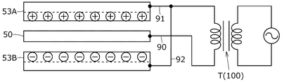
第1電極54Aは、第1エレクトレットボード53Aと共に、第1変換器5Aの固定極(背極)56Aを構成する。固定極56Aは、振動板50と共に第1コンデンサを構成する。第1電極54Aの材料は、例えば、銅合金などの導電性を有する金属である。第1電極54Aの形状は、矩形枠である。第1電極54Aは、第2突出電極部54Aaを備える。第2突出電極部54Aaは、後述するコード9の第2信号線91に接続する。第2突出電極部54Aaは、第1電極54Aの左辺の長手方向の下半部から左方に向かって突出する。第1電極54Aは、第1エレクトレットボード53Aの前方に配置される。第1電極54Aの後面は、第1エレクトレットボード53Aの前面の周縁部に当接する。
The
第1インシュレータ55Aは、固定極56Aをハウジング1から絶縁する。第1インシュレータ55Aの材料は、例えば、PC(ポリカーボネート)などの絶縁性の合成樹脂である。第1インシュレータ55Aの形状は、矩形枠である。第1インシュレータ55Aは、段部55Aaと切欠溝(不図示)とを備える。段部55Aaは、固定極56Aを嵌合する。段部55Aaは、第1インシュレータ55Aの前面の内周縁に配置される(図5参照)。切欠溝は、第2突出電極部54Aaを嵌合する。切欠溝は、第1インシュレータ55Aの左辺の下半部に配置される。
The
第1変換器5Aにおいて、振動板50と第1エレクトレットボード53Aとの間には、第1振動板フレーム51Aの厚さと第1スペーサ52Aの厚さとに相当する幅の隙間(以下「第1薄空気層」という。)S1が形成される。
In the
第2変換器5Bは、振動板50と、第2振動板フレーム51Bと、第2スペーサ52Bと、第2エレクトレットボード53Bと、第2電極54Bと、第2インシュレータ55Bと、を備える。前述したとおり、振動板50は、第1変換器5Aと第2変換器5Bとで共用される。
The
第2振動板フレーム51Bの構成は、第1振動板フレーム51Aの構成と同じである。第2振動板フレーム51Bは、第1突出電極部51Baを備える。第1突出電極部51Baは、第1振動板フレーム51Aの第1突出電極部51Aaに当接する。
The configuration of the
第2スペーサ52Bの構成は、第1スペーサ52Aの構成と同じである。第2スペーサ52Bは、第2振動板フレーム51Bの後方に配置される。第2スペーサ52Bの前面は、第2振動板フレーム51Bの後面に当接する。
The configuration of the
第2エレクトレットボード53Bの構成は、第2エレクトレットボード53Bが保持する電荷の正負を除き、第1エレクトレットボード53Aの構成と同じである。第2エレクトレットボード53Bは、複数の音孔53Bhを備える。第2エレクトレットボード53Bの電荷については後述する。第2エレクトレットボード53Bは、第2スペーサ52Bの後方に配置される。第2エレクトレットボード53Bの前面の周縁部は、第2スペーサ52Bの後面に当接する。
The configuration of the
第2電極54Bの構成は、第2突出電極部54Aaの代わりに第3突出電極部54Baが形成される点を除き、第1電極54Aの構成と同じである。第3突出電極部54Baは、後述するコード9の第3信号線92に接続する。第3突出電極部54Baは、第2電極54Bの左辺の長手方向の上半部から左方に向かって突出する。第2電極54Bは、第2エレクトレットボード53Bの後方に配置される。第2電極54Bの前面は、第2エレクトレットボード53Bの後面の周縁部に当接する。第2電極54Bは、第2エレクトレットボード53Bと共に、第2変換器5Bの固定極56Bを構成する。固定極56Bは、振動板50と共に、第2コンデンサを構成する。
The configuration of the
第2インシュレータ55Bの構成は、切欠溝の位置を除き、第1インシュレータ55Aの構成と同じである。第2インシュレータ55Bは、切欠溝55Bbを備える。切欠溝55Bbは、第3突出電極部54Baを嵌合する。切欠溝55Bbは、第2インシュレータ55Bの左辺の上半部に配置される。
The configuration of the
第2変換器5Bにおいて、振動板50と第2エレクトレットボード53Bとの間には、第2振動板フレーム51Bの厚さと第2スペーサ52Bの厚さとに相当する幅の隙間(以下「第2薄空気層」という。)S2が形成される。
In the
電気音響変換器5は、振動板50の前後を、第1変換器5Aの固定極56Aと、第2変換器5Bの固定極56Bとで挟むことで構成される。そのため、振動板50は、いわゆるプッシュプルで駆動する。
The
電気音響変換器5は、ハウジング1の収納室R1に収納される。第1インシュレータ55Aの前面は、ハウジング1の内壁10bに囲われた前壁10aの内面に当接する。第1振動板フレーム51Aの外周面と、第1インシュレータ55Aの外周面と、第2振動板フレーム51Bの外周面と、第2インシュレータ55Bの外周面とは、ハウジング1の内壁10bの内周面に当接する。
The
図7は、第1エレクトレットボード53Aが保持する電荷と、第2エレクトレットボード53Bが保持する電荷と、を示した説明図である。
同図中の破線は、第1エレクトレットボード53Aの真鍮板とFEP膜との境界と、第2エレクトレットボード53Bの真鍮板とFEP膜との境界と、を示す。
FIG. 7 is an explanatory diagram showing electric charges held by the
The broken lines in the figure indicate the boundary between the brass plate of the
第1エレクトレットボード53AのFEP膜は、プラスの電荷を保持している。第2エレクトレットボード53BのFEP膜は、マイナスの電荷を保持している。振動板50は、プラスの電荷を保持した第1エレクトレットボード53Aと、マイナスの電荷を保持した第2エレクトレットボード53Bと、により挟み込まれる。そのため、電気音響変換器5は、いわゆるコンプリメンタリバックエレクトレット型のコンデンサユニットとして構成される。
The FEP film of the
なお、例えば、第1エレクトレットボードのFEP膜がマイナスの電荷を保持し、第2エレクトレットボードのFEP膜がプラスの電荷を保持してもよい。 Note that, for example, the FEP film of the first electret board may hold negative charges, and the FEP film of the second electret board may hold positive charges.
図8は、図4に示した本体LEBから、後部ハウジング半体11を取り外した状態の外観図である。同図は、配線室R2の内部の図示を省略している。
FIG. 8 is an external view of the main body LEB shown in FIG. 4 with the
固定部材6は、電気音響変換器5をハウジング1の収納室R1に固定する。固定部材6の材料は、例えば、アルミニウムなどの金属である。固定部材6の形状は、矩形枠である。固定部材6は、複数の固定部60を備える。固定部60は、固定部材6の4隅のそれぞれの外周縁から左右方向(紙面左右方向)に向かって突出する。固定部60は、ねじ挿通孔60hを備える。ねじ挿通孔60hは、固定ねじ(不図示)が挿通される孔である。固定部材6は、電気音響変換器5の後方(図の手前方向)に配置される。固定部材6の前面は、第2インシュレータ55Bの後面に当接する。
The fixing
固定部材6は、固定ねじによりハウジング1に締結される。その結果、電気音響変換器5は、ハウジング1に固定される。第1突出電極部51Aaと、第1突出電極部51Baと、第2突出電極部54Aaと、第3突出電極部54Baとは、ハウジング1の配線室R2内に突出して配置される。
The fixing
図5に戻る。
電気音響変換器5の前面は、ハウジング1の前壁10aの凹部10cに対向する。その結果、ハウジング1の内部における振動板50の前方には、第1薄空気層S1と第1空間S3とが配置される。第1空間S3は、第1電極54Aと第1インシュレータ55Aと凹部10cと前部放音孔10hとにより囲まれた空間である。
Referring back to FIG.
The front surface of the
一方、電気音響変換器5の後面は、ハウジング1の後壁11aの凹部11bに対向する。その結果、ハウジング1の内部における振動板50の後方には、第2薄空気層S2と、第2空間S4と、後述する第2防護材71と、後部孔11hと、が配置される。第2空間S4は、第2電極54Bと第2インシュレータ55Bと固定部材6とにより囲まれた空間である。
On the other hand, the rear surface of the
防護材7は、ハウジング1の内部への異物や汗などの侵入を防ぐ。防護材7は、第1防護材70と第2防護材71とを備える。
The
第1防護材70の材料は、撥水処理された金属繊維である。第1防護材70の形状は、円板である。第1防護材70は、音導管3の前端に取り付けられる。第1防護材70は、音導管3の前端側の開口を塞ぐ。その結果、音導管3は、内部に音導管内空間S5を有する。音導管内空間S5は、音導管3と第1防護材70とにより囲まれた空間である。音導管内空間S5は、第1空間S3と連通する。第1防護材70は、イヤホンEの周波数特性などを調整する音響抵抗材としての機能も備える。
The material of the first
第2防護材71の材料は、撥水性の金属メッシュである。第2防護材71の形状は、矩形板である。第2防護材71は、ハウジング1の後壁11aの内面に取り付けられる。第2防護材71は、後部孔11hをハウジング1の内側から塞ぐ。第2防護材71は、音響抵抗材としての機能を備えてもよい。
The material of the second
なお、第2防護材の材料は、第1防護材の材料と同じでもよい。 Note that the material of the second protective material may be the same as the material of the first protective material.
第1空間S3は、音導管内空間S5と共に前部気室R3を構成する。前部気室R3は、第1防護材70とイヤピース4の内筒部41の前半部内の空間(以下「内筒部内空間」という。)S6と、を介してイヤピース4の前方(外部)の空間と連通する。前部気室R3は、第1エレクトレットボード53Aの音孔53Ahを介して、第1薄空気層S1と連通する。
The first space S3 forms a front air chamber R3 together with the space S5 in the sound conduit. The front air chamber R3 is located in front (outside) of the
第2空間S4は、後部気室R4を構成する。後部気室R4は、第2防護材71と後部孔11hと、を介してハウジング1の後方(外部)の空間と連通する。すなわち、後部孔11hは、ハウジング1の内部の空間とハウジング1の外部の空間と、を連通させる連通孔である。後部気室R4は、第2エレクトレットボード53Bの音孔53Bhを介して、第2薄空気層S2と連通する。
The second space S4 forms a rear air chamber R4. The rear air chamber R4 communicates with the space behind (external to) the
前部気室R3の容積は後部気室R4の容積よりも小さい。第1薄空気層S1の容積は第2薄空気層S2の容積と同じである。すなわち、ハウジング1の内部における振動板50の前方の空間の容積と音導管内空間S5の容積との和は、ハウジング1の内部における振動板50の後方の空間の容積よりも小さい。
The volume of the front air chamber R3 is smaller than the volume of the rear air chamber R4. The volume of the first thin air layer S1 is the same as the volume of the second thin air layer S2. That is, the sum of the volume of the space in front of the
コードブッシュ8はコード9を折り曲げや断線などから保護する。コードブッシュ8の材料は柔軟性を有するゴムなどの合成樹脂である。コードブッシュ8の形状は略円筒である。コードブッシュ8は環状の溝80を備える。溝80はハウジング1の嵌合孔1hに嵌合される。溝80はコードブッシュ8の一端側の外周面に配置される。
The
コード9は電気音響変換器5にイヤホンEの外部の音源からの音声信号を伝達する。コード9は、例えば、第1信号線(基準電位線)90と第2信号線91と第3信号線92とを有する3芯コードである(図7参照)。コード9の一端はコードブッシュ8に挿通されてハウジング1の配線室R2に収納される。コード9の他端には、例えば、ステレオプラグ(不図示)が取り付けられる。
The
第1信号線90は第1突出電極部51Aaと第1突出電極部51Baとに接続される。第2信号線91は第2突出電極部54Aaに接続される。第3信号線92は第3突出電極部54Baに接続される。
The
図3と図5とに戻る。
カバー部材LECはハウジング1の後部孔11hを後方から覆う。カバー部材LECは本発明にかかるイヤホンの開閉機構の例である。カバー部材LECの材料は、例えば、シリコンゴムなどの弾性を有する合成樹脂である。カバー部材LECの形状は前方に開口する矩形皿状である。カバー部材LECは、矩形の天井部と天井部を矩形に囲む周壁と、を備える。周壁の内周の大きさはハウジング1の周壁の大きさより僅かに小さい。
Returning to FIG. 3 and FIG.
The cover member LEC covers the
周壁は第1切欠部LEC1と第2切欠部(不図示)とを備える。第1切欠部LEC1はコードブッシュ8との干渉を避ける。第1切欠部LEC1の形状は逆Uの字状である。第1切欠部LEC1は、周壁のうち、下方に面する部分に配置される。第2切欠部はハンガー2の連結部材20との干渉を避ける。第2切欠部は、周壁のうち、左方に面する部分に配置される。
The peripheral wall includes a first cutout LEC1 and a second cutout (not shown). The first notch LEC1 avoids interference with the
カバー部材LECは後方からハウジング1に着脱可能に被せられる。ハウジング1の後部孔11hは、カバー部材LECにより外側から塞がれる。すなわち、カバー部材LECは、後部孔11hを開閉する。つまり、後部孔11hは、カバー部材LECがハウジング1に取り付けられると閉鎖される。このとき、後部気室R4はハウジング1の外部の空間に対して密閉される。後部孔11hは、カバー部材LECがハウジング1から取り外されると開放される。後部孔11hが開放されたとき、後部気室R4はハウジング1の外部の空間に対して開放される。
The cover member LEC is detachably mounted on the
カバー部材LECはハウジング1の後壁11aと周壁とを覆う。このとき、カバー部材LECの周壁はハウジング1により押し広げられる。そのため、カバー部材LECの内面とハウジング1の外面との間には、強い摩擦力が生じる。その結果、カバー部材LECはハウジング1に固定される。
The cover member LEC covers the
イヤホンEは、ステレオプラグを介して、イヤホンEの外部の昇圧ユニット100に接続される。昇圧ユニット100は音源からの音声信号を昇圧する。昇圧ユニット100は内部に昇圧トランスTを備える。昇圧ユニット100は、コード9と外部の音源との間に接続される。昇圧トランスTは、音源からの音声信号を昇圧して、コード9に伝送する。
The earphone E is connected to a boosting
なお、イヤホンEはバックエレクトレット型であるため、高電圧の直流バイアスを発生させる電源は不要である。 Since the earphone E is a back electret type, a power source for generating a high-voltage DC bias is not required.
●イヤホンの動作
次に、イヤホンEの動作について説明する。
Next, the operation of the earphone E will be described.
まず、本体LEBにカバー部材LECが取り付けられた状態のイヤホンEの動作について説明する。 First, an operation of the earphone E in a state where the cover member LEC is attached to the main body LEB will be described.
図9は、カバー部材LECが取り付けられた本体LEBが使用者の左耳に装着された状態の断面図である。同図は、外耳道Ecを簡略化して示している。同図は、前部気室R3と後部気室R4とを明確化するために、一部の線の図示を省略している。 FIG. 9 is a cross-sectional view illustrating a state where the main body LEB to which the cover member LEC is attached is attached to the left ear of the user. This figure shows the ear canal Ec in a simplified manner. In the figure, some lines are omitted to clarify the front air chamber R3 and the rear air chamber R4.
本体LEBが使用者の左耳に装着されると、イヤピース4は、使用者の外耳道Ecに挿入される。イヤピース4は、変形して外耳道Ecの内面に密着する。外耳道Ecの内側には、イヤピース4と外耳道Ecと鼓膜(不図示)とにより囲まれた空間(以下「外耳道内空間」という。)S7が形成される。
When the main body LEB is mounted on the left ear of the user, the
音源から電気音響変換器5に音声信号が供給されると、振動板50は、プッシュプルで駆動して、音声信号に応じた音圧を発生させる。振動板50からの音圧は、振動板50近傍の空気に伝播して、振動板50の前方に向けて音波として進行する。
When a sound signal is supplied from the sound source to the
振動板50の前方に進行する音波は、第1薄空気層S1と、第1エレクトレットボード53Aの音孔53Ahと、前部気室R3と、第1防護材70と、内筒部内空間S6と、外耳道内空間S7と、を通って使用者の鼓膜に到達する。
The sound wave traveling in front of the
一方、振動板50の後方に発生した音圧は、第2薄空気層S2と、第2エレクトレットボード53Bの音孔53Bhと、を通って後部気室R4に到達する。後部気室R4は、ハウジング1の外部の空間に対して密閉されている。すなわち、後部気室R4は、後部気室R4に到達した音圧を制御する音響インピーダンスとして機能する。そのため、カバー部材LECが取り付けられた状態のイヤホンEは、密閉型のイヤホンとして機能する。
On the other hand, the sound pressure generated behind the
次に、イヤホンEが密閉型のイヤホンとして機能する場合の等価回路について説明する。 Next, an equivalent circuit when the earphone E functions as a closed earphone will be described.
図10は、密閉型のイヤホンとして機能するイヤホンEの等価回路図である。
図10に示す符号は、以下のとおりである。符号Feは、振動板50の音圧を示す。符号s0は、振動板50のスチフネスを示す。符号s1は、第1薄空気層S1のスチフネスを示す。符号s2は、前部気室R3のスチフネスを示す。符号s3は、第2薄空気層S2のスチフネスを示す。符号s4は、後部気室R4のスチフネスを示す。符号m0は、振動板50の質量を示す。符号m1は、第1エレクトレットボード53Aの音孔53Ah内の空気の質量を示す。符号m2は、第2エレクトレットボード53Bの音孔53Bh内の空気の質量を示す。符号r0は、第1エレクトレットボード53Aの音孔53Ah内の空気の音響抵抗を示す。符号r1は、第1防護材70の音響抵抗を示す。符号r2は、第2エレクトレットボード53Bの音孔53Bh内の空気の質量を示す。符号ZEは、外耳道Ec内の負荷インピーダンスを示す。
FIG. 10 is an equivalent circuit diagram of an earphone E functioning as a closed earphone.
The reference numerals shown in FIG. 10 are as follows. The symbol Fe indicates the sound pressure of the
密閉型のイヤホンとして機能するイヤホンEにおいて、後部孔11hは、カバー部材LECにより閉鎖される。すなわち、後部気室R4は、カバー部材LECにより閉じた空間となる。このとき、振動板50の振動は、第1薄空気層S1のスチフネスs1と、前部気室R3のスチフネスs2と、第2薄空気層S2のスチフネスs3と、後部気室R4のスチフネスs4と、による制動を受ける。
In the earphone E functioning as a closed earphone, the
一般的に、ある空間を占める空気のスチフネスは、その空気の体積に反比例する。ここで、前述のとおり、前部気室R3の容積は、後部気室R4の容積よりも小さい。すなわち、前部気室R3のスチフネスs2は、後部気室R4のスチフネスs4よりも大きい。そのため、後部気室R4のスチフネスs4は、後部気室R4の空間の容積を前部気室R3の空間の容積よりも大きくすることで、前部気室R3のスチフネスs2に大きな影響を与えない。 Generally, the stiffness of air occupying a space is inversely proportional to the volume of the air. Here, as described above, the volume of the front air chamber R3 is smaller than the volume of the rear air chamber R4. That is, the stiffness s2 of the front air chamber R3 is larger than the stiffness s4 of the rear air chamber R4. Therefore, the stiffness s4 of the rear air chamber R4 does not significantly affect the stiffness s2 of the front air chamber R3 by making the volume of the space of the rear air chamber R4 larger than the volume of the space of the front air chamber R3. .
また、振動板50は、第1薄空気層S1と第2薄空気層S2とに挟まれている。第1薄空気層S1のスチフネスs1は、前部気室R3のスチフネスs2と後部気室R4のスチフネスs4のそれぞれよりも大きい。第2薄空気層S2のスチフネスs3は、前部気室R3のスチフネスs2と後部気室R4のスチフネスs4のそれぞれよりも大きい。そのため、振動板50の振動への影響については、第1薄空気層S1のスチフネスs1と第2薄空気層S2のスチフネスs3とが支配的となる。その結果、密閉型のイヤホンとして機能するイヤホンEにおいて、振動板50の振動は、後部気室R4のスチフネスs4による制動を受けるが、過剰な制動を受けない。
The
次に、本体LEBからカバー部材LECが取り外された状態のイヤホンEの動作について説明する。 Next, the operation of the earphone E with the cover member LEC removed from the main body LEB will be described.
図11は、本体LEBからカバー部材LECが取り外された状態のイヤホンEが使用者の左耳に装着された状態の断面図である。同図は、使用者の外耳道Ecを簡略化して示している。同図は、前部気室R3と後部気室R4とを明確化するために、一部の線の図示を省略している。 FIG. 11 is a cross-sectional view illustrating a state in which the earphone E with the cover member LEC removed from the main body LEB is attached to the left ear of the user. This figure shows the user's external auditory meatus Ec in a simplified manner. In the figure, some lines are omitted to clarify the front air chamber R3 and the rear air chamber R4.
振動板50の前方に発生した音圧は、本体LEBにカバー部材LECが取り付けられた状態と同様に、使用者の鼓膜に音波として到達する。
The sound pressure generated in front of the
一方、振動板50の後方に発生した音圧は、第2薄空気層S2と、第2エレクトレットボード53Bの音孔53Bhと、を通って後部気室R4に到達する。後部気室R4は、後部孔11hを介して、ハウジング1の外部の空間に対して開放されている。このとき、後部気室R4のスチフネスs4は、外部と連通しているため、小さくなる。そのため、後部気室R4に到達した音圧は、後部気室R4のスチフネスs4により制限されることなく、後部孔11hから、ハウジング1の外部の空間に音波として放出される。すなわち、カバー部材LECが取り外された状態のイヤホンEは、開放型のイヤホンとして機能する。
On the other hand, the sound pressure generated behind the
次に、イヤホンEが開放型のイヤホンとして機能する場合の等価回路について説明する。 Next, an equivalent circuit when the earphone E functions as an open earphone will be described.
図12は、開放型のイヤホンとして機能するイヤホンEの等価回路図である。
図12に示す符号は、図11に示す符号と同じである。
FIG. 12 is an equivalent circuit diagram of an earphone E functioning as an open earphone.
The reference numerals shown in FIG. 12 are the same as those shown in FIG.
イヤホンEが開放型のイヤホンとして機能する場合、後部気室R4は、後部孔11hを介してハウジング1の外部の空間と連通する。また、第2防護材71は、金属メッシュであり、第1防護材70よりも空気を通しやすい。そのため、後部気室R4のスチフネスs4は、ハウジング1の外部の空間の一部とみなすことができる。したがって、後部気室R4のスチフネスs4は、イヤホンEの等価回路において無視することができる程度に小さくなる。すなわち、振動板50の振動は、後部気室R4のスチフネスs4による制動を受けない。このとき、振動板50の振動は、第1薄空気層S1のスチフネスs1と、前部気室R3のスチフネスs2と、第2薄空気層S2のスチフネスs3と、による制動を受ける。
When the earphone E functions as an open earphone, the rear air chamber R4 communicates with the space outside the
イヤホンEが開放型のイヤホンとして機能する場合においても、前部気室R3のスチフネスs2は、後部気室R4のスチフネスs4よりも大きい。そのため、後部気室R4のスチフネスs4は、前部気室R3のスチフネスs2に大きな影響を与えない。すなわち、開放型のイヤホンとして機能するイヤホンEの各空間のスチフネスのバランスは、密閉型のイヤホンとして機能するイヤホンEの各空間のスチフネスのバランスと比較して、大きく変動しない。 Even when the earphone E functions as an open earphone, the stiffness s2 of the front air chamber R3 is larger than the stiffness s4 of the rear air chamber R4. Therefore, the stiffness s4 of the rear air chamber R4 does not significantly affect the stiffness s2 of the front air chamber R3. That is, the stiffness balance of each space of the earphone E functioning as an open type earphone does not fluctuate significantly as compared with the stiffness balance of each space of the earphone E functioning as a closed earphone.
また、前述のとおり、振動板50の振動へ与える影響においては、第1薄空気層S1のスチフネスs1と第2薄空気層S2のスチフネスs3とが支配的となる。その結果、開放型のイヤホンとして機能するイヤホンEにおいて、振動板50の振動は、後部気室R4のスチフネスs4による制動を受けない。すなわち、イヤホンEの周波数特性は、密閉型または開放型の違いによる後部気室R4のスチフネスの変化の影響をほとんど受けない。したがって、イヤホンEの周波数特性は、密閉型または開放型に関わらず劣化しない。すなわち、イヤホンEは、使用者の好みに応じて、密閉型または開放型を選択可能である。つまり、本実施の形態にかかるイヤホンEは、密閉型のイヤホンの機能と、開放型のイヤホンの機能と、を切り換え可能にすると共に、いずれの機能を提供する状態においても音響的に良好な設計となる。
As described above, the stiffness s1 of the first thin air layer S1 and the stiffness s3 of the second thin air layer S2 are dominant in affecting the vibration of the
このように、開放型のイヤホンとして機能するイヤホンEの周波数特性は、密閉型のイヤホンとして機能するイヤホンEの周波数特性と比べて大きく変動しない。つまり、イヤホンEは、本体LEBに対するカバー部材LECの着脱により、開放型のイヤホンの機能と密閉型のイヤホンの機能とを切り換えることができる。 As described above, the frequency characteristics of the earphone E functioning as an open earphone do not fluctuate significantly as compared with the frequency characteristics of the earphone E functioning as a closed earphone. That is, the earphone E can switch between the function of the open earphone and the function of the closed earphone by attaching and detaching the cover member LEC to and from the main body LEB.
また、イヤホンEは、音導管3とイヤピース4とを備えるカナル型(インナーイヤー型)のイヤホンである。そのため、イヤホンEが使用者の耳に装着されると、振動板50と鼓膜との間隔は、例えば、耳覆い型のヘッドホンなど(以下「ヘッドホン」という。)と比べて近づく。また、振動板50から鼓膜に至るまでの空間の容積は、ヘッドホンと比べて小さい。そのため、イヤホンEの振動板50は、ヘッドホンの振動板よりも小さくできる。その結果、イヤホンEの振動板50のスチフネスs0は、ヘッドホンの振動板のスチフネスに比べて大きくできる。
The earphone E is a canal-type (inner-ear) earphone including the
●まとめ
以上説明した実施の形態によれば、イヤホンEにおいて、外耳道内空間S7に連通する前部気室R3の容積は、後部孔11hを介してハウジング1の外部と連通する後部気室R4の容積よりも小さい。また、イヤホンEは、後部孔11hを覆うカバー部材LECを着脱可能に備える。そのため、イヤホンEは、本体LEBに対するカバー部材LECの着脱により、開放型のイヤホンの機能と密閉型のイヤホンの機能とを切り換えることができる。その結果、イヤホンEの周波数特性は、開放型のイヤホンとして動作するときと、密閉型のイヤホンとして動作するときと、で大きく変動しない。つまり、イヤホンEは、コンデンサ型の電気音響変換器5を用いつつ、開放型のイヤホンの機能と密閉型のイヤホンの機能とを両立させる。
Conclusion According to the embodiment described above, in the earphone E, the volume of the front air chamber R3 communicating with the space S7 in the external auditory canal is equal to the volume of the rear air chamber R4 communicating with the outside of the
なお、以上説明した実施の形態は、開閉機構であるカバー部材LECが複数の後部孔11hの全てを覆う構成である。しかし、本発明にかかるイヤホンが備える開閉機構は、後部孔11hの一部のみを閉鎖してもよい。閉鎖される後部孔11hの数は、イヤホンEが出力する音の聴感上の音質を変える。そのため、開閉機構により閉鎖される後部孔11hの数が可変であれば、使用者は、趣向に合わせた音響的な設定を選択することができる。
In the embodiment described above, the cover member LEC as the opening / closing mechanism covers all of the plurality of
また、開閉機構の構成は、本実施の形態に限定されない。すなわち、例えば、ハウジングは、後部孔と同様の形態の開口を有するスライド板と、スライド板をスライドさせるスライド機構と、を備えてもよい。スライド板は、本発明にかかるイヤホンが備える開閉機構の閉鎖部の例である。スライド機構は、本発明にかかるイヤホンの開閉機構が備える移動部の例である。スライド機構の一部は、ハウジングの外部に露出されてもよい。この場合、ハウジングの外部の空間に対する後部気室の開放と密閉とは、スライド機構の露出した部分が使用者の指などで操作されることで適宜選択される。 Further, the configuration of the opening / closing mechanism is not limited to this embodiment. That is, for example, the housing may include a slide plate having an opening having the same form as the rear hole, and a slide mechanism for sliding the slide plate. The slide plate is an example of a closing portion of the opening / closing mechanism included in the earphone according to the present invention. The slide mechanism is an example of a moving unit included in the earphone opening / closing mechanism according to the present invention. A part of the slide mechanism may be exposed outside the housing. In this case, the opening and closing of the rear air chamber with respect to the space outside the housing are appropriately selected by operating the exposed portion of the slide mechanism with the user's finger or the like.
さらに、開閉機構の構成は、例えば、開閉式の扉構造であってもよい。 Further, the configuration of the opening and closing mechanism may be, for example, an opening and closing type door structure.
さらにまた、本実施形態にかかるイヤホンEは、コードブッシュ8とコード9とを備える。しかし、本発明にかかるイヤホンは、コードブッシュとコードとの代わりに、ジャックなどのコネクタを備える構成でもよい。
Furthermore, the earphone E according to the present embodiment includes a
E イヤホン
LE 左イヤホンユニット
RE 右イヤホンユニット
LEB 本体
LEC カバー部材
1 ハウジング
10c 凹部
10h 前部放音孔
11b 凹部
11h 後部孔
2 ハンガー
3 音導管
4 イヤピース
5 電気音響変換器
50 振動板
5A 第1変換器
51A 第1振動板フレーム
52A 第1スペーサ
53A 第1エレクトレットボード
53Ah 音孔
54A 第1電極
55A 第1インシュレータ
5B 第2変換器
51B 第2振動板フレーム
52B 第2スペーサ
53B 第2エレクトレットボード
53Bh 音孔
54B 第2電極
55B 第2インシュレータ
6 固定部材
7 防護材
70 第1防護材
71 第2防護材
8 コードブッシュ
9 コード
S1 第1薄空気層
S2 第2薄空気層
S3 第1空間
S4 第2空間
S5 音導管内空間
S6 内筒部内空間
S7 外耳道内空間
R3 前部気室
R4 後部気室
E earphone LE left earphone unit RE right earphone unit LEB main body
Claims (9)
前記振動板との間でコンデンサを構成する固定極と、
前記振動板と前記固定極とを収納するハウジングと、
前記ハウジングの前方に突設される音導管と、
前記ハウジングの外部と前記ハウジングの内部とを連通させる連通孔と、
前記連通孔を開閉する開閉機構と、
を有してなり、
前記音導管の内部の空間の容積と、前記ハウジングの内部の空間のうち前記音導管の内部の空間と連通する前記振動板の前方の空間の容積と、の和は、前記ハウジングの内部の空間のうち前記振動板の後方の空間の容積よりも小さく、
前記開閉機構が前記連通孔を開放したとき、開放型のイヤホンとして機能し、
前記開閉機構が前記連通孔を閉鎖したとき、密閉型のイヤホンとして機能する、
ことを特徴とするイヤホン。 A diaphragm,
Fixed poles constituting a capacitor between the diaphragm,
A housing for housing the diaphragm and the fixed pole,
A sound conduit protruding from the front of the housing;
A communication hole for communicating the outside of the housing and the inside of the housing,
An opening and closing mechanism for opening and closing the communication hole;
Having,
The sum of the volume of the space inside the sound conduit and the volume of the space in front of the diaphragm that communicates with the space inside the sound conduit out of the space inside the housing is the space inside the housing. rather smaller than the volume of the space behind the diaphragm of,
When the opening / closing mechanism opens the communication hole, it functions as an open-type earphone,
When the opening and closing mechanism closes the communication hole, it functions as a closed earphone.
An earphone characterized by the following.
請求項1記載のイヤホン。 The communication hole is disposed behind the diaphragm.
The earphone according to claim 1.
前記開閉機構は、複数の前記連通孔の一部のみを閉鎖する、
請求項1記載のイヤホン。 A plurality of the communication holes are arranged in the housing,
The opening and closing mechanism closes only a part of the plurality of communication holes,
The earphone according to claim 1.
請求項2記載のイヤホン。 The opening and closing mechanism is detachable from the housing.
The earphone according to claim 2.
請求項4記載のイヤホン。 The opening and closing mechanism is a cover member that covers the rear of the housing.
The earphone according to claim 4.
請求項5記載のイヤホン。 The cover member is made of an elastic resin,
The earphone according to claim 5.
前記振動板は、前記第1固定極と前記第2固定極とで挟まれる、
請求項1記載のイヤホン。 The fixed pole includes a first fixed pole and a second fixed pole,
The diaphragm is sandwiched between the first fixed pole and the second fixed pole,
The earphone according to claim 1.
前記連通孔を閉鎖する閉鎖部と、
前記閉鎖部を移動させる移動部と、
を備える、
請求項1記載のイヤホン。 The opening and closing mechanism includes:
A closing portion for closing the communication hole;
A moving unit for moving the closing unit;
Comprising,
The earphone according to claim 1.
請求項8記載のイヤホン。 Part of the moving portion is exposed outside the housing,
An earphone according to claim 8.
Priority Applications (2)
| Application Number | Priority Date | Filing Date | Title |
|---|---|---|---|
| JP2016064814A JP6668138B2 (en) | 2016-03-29 | 2016-03-29 | earphone |
| US15/471,627 US10313774B2 (en) | 2016-03-29 | 2017-03-28 | Earphone |
Applications Claiming Priority (1)
| Application Number | Priority Date | Filing Date | Title |
|---|---|---|---|
| JP2016064814A JP6668138B2 (en) | 2016-03-29 | 2016-03-29 | earphone |
Publications (3)
| Publication Number | Publication Date |
|---|---|
| JP2017183851A JP2017183851A (en) | 2017-10-05 |
| JP2017183851A5 JP2017183851A5 (en) | 2019-02-28 |
| JP6668138B2 true JP6668138B2 (en) | 2020-03-18 |
Family
ID=59962146
Family Applications (1)
| Application Number | Title | Priority Date | Filing Date |
|---|---|---|---|
| JP2016064814A Active JP6668138B2 (en) | 2016-03-29 | 2016-03-29 | earphone |
Country Status (2)
| Country | Link |
|---|---|
| US (1) | US10313774B2 (en) |
| JP (1) | JP6668138B2 (en) |
Families Citing this family (7)
| Publication number | Priority date | Publication date | Assignee | Title |
|---|---|---|---|---|
| KR101952906B1 (en) * | 2017-12-20 | 2019-02-28 | 부전전자 주식회사 | Acoustic device having multiple vibration plates |
| US10390143B1 (en) * | 2018-02-15 | 2019-08-20 | Bose Corporation | Electro-acoustic transducer for open audio device |
| JP7149585B2 (en) | 2018-12-17 | 2022-10-07 | 株式会社オーディオテクニカ | Electroacoustic transducer and electroacoustic transducer |
| KR102161637B1 (en) * | 2019-01-22 | 2020-10-05 | 부전전자 주식회사 | Acoustic device having multiple vibration plates |
| EP4087275A4 (en) * | 2020-03-30 | 2023-06-14 | Audio-Technica Corporation | Capacitive electro-acoustic conversion device |
| JP2023084840A (en) * | 2021-12-08 | 2023-06-20 | 株式会社オーディオテクニカ | Electroacoustic transducer |
| CN115209303A (en) * | 2022-08-26 | 2022-10-18 | 惠州市大康科技有限公司 | Bone conduction earphone and manufacturing method thereof |
Family Cites Families (14)
| Publication number | Priority date | Publication date | Assignee | Title |
|---|---|---|---|---|
| DE19612481C2 (en) * | 1996-03-29 | 2003-11-13 | Sennheiser Electronic | Electrostatic converter |
| US7634099B2 (en) * | 2005-07-22 | 2009-12-15 | Logitech International, S.A. | High-fidelity earpiece with adjustable frequency response |
| US8594351B2 (en) * | 2006-06-30 | 2013-11-26 | Bose Corporation | Equalized earphones |
| JP4957367B2 (en) * | 2007-05-09 | 2012-06-20 | 株式会社Jvcケンウッド | earphone |
| US8111853B2 (en) * | 2008-07-10 | 2012-02-07 | Plantronics, Inc | Dual mode earphone with acoustic equalization |
| CN102006533B (en) * | 2009-08-31 | 2014-08-27 | 富准精密工业(深圳)有限公司 | Earphone |
| US20120314882A1 (en) * | 2009-11-23 | 2012-12-13 | Incus Laboratories Limited | Production of ambient noise-cancelling earphones |
| WO2013014852A1 (en) * | 2011-07-22 | 2013-01-31 | パナソニック株式会社 | Earphone |
| KR101165663B1 (en) * | 2011-12-27 | 2012-07-16 | 필스전자 주식회사 | Earphone with open-close type enclosure |
| US9210497B2 (en) * | 2012-09-06 | 2015-12-08 | Shure Acquisition Holdings, Inc. | Electrostatic earphone |
| US8989427B2 (en) * | 2013-06-06 | 2015-03-24 | Bose Corporation | Earphones |
| CN105723737B (en) * | 2013-11-19 | 2019-03-19 | 索尼公司 | Earphone and acoustic characteristic method of adjustment |
| US9363594B2 (en) * | 2013-12-13 | 2016-06-07 | Apple Inc. | Earbud with membrane based acoustic mass loading |
| US9578412B2 (en) * | 2014-06-27 | 2017-02-21 | Apple Inc. | Mass loaded earbud with vent chamber |
-
2016
- 2016-03-29 JP JP2016064814A patent/JP6668138B2/en active Active
-
2017
- 2017-03-28 US US15/471,627 patent/US10313774B2/en not_active Expired - Fee Related
Also Published As
| Publication number | Publication date |
|---|---|
| JP2017183851A (en) | 2017-10-05 |
| US20170289667A1 (en) | 2017-10-05 |
| US10313774B2 (en) | 2019-06-04 |
Similar Documents
| Publication | Publication Date | Title |
|---|---|---|
| JP6668138B2 (en) | earphone | |
| KR101039813B1 (en) | A dual earphone have the bone conductive and the air conductive | |
| US20210099786A1 (en) | Earphone | |
| JP4652474B1 (en) | earphone | |
| KR101423570B1 (en) | Earphone | |
| TW201208400A (en) | Earphone assembly | |
| KR101092958B1 (en) | Earset | |
| JP7240734B2 (en) | wireless earphones | |
| JP2020098957A (en) | Electroacoustic transducer and electroacoustic transducing device | |
| WO2023050984A1 (en) | Earphone | |
| JP2007174165A (en) | Microphone, and hearing aid using same | |
| KR101634236B1 (en) | Acoustic Hybrid Earphone With Acoustic Filter | |
| EP3200476B1 (en) | Headphone | |
| JP5872722B1 (en) | Earphone with communication pipe | |
| JP5849296B1 (en) | Sealed earphone with communication part | |
| JP5625928B2 (en) | Earphone for TV program appearance | |
| WO2023051005A1 (en) | Coil-iron loudspeaker assembly and earphone | |
| WO2006134564A1 (en) | In-ear phone | |
| TWI643188B (en) | Microphone device | |
| CN216414550U (en) | Earphone set | |
| US11895459B2 (en) | Sound output device | |
| WO2020148819A1 (en) | Intra-concha earphones | |
| KR100931022B1 (en) | Earphone | |
| TWI749988B (en) | Speaker unit with dual diaphragms and dual coils | |
| JP2020043547A (en) | Earphone speaker |
Legal Events
| Date | Code | Title | Description |
|---|---|---|---|
| A521 | Request for written amendment filed |
Free format text: JAPANESE INTERMEDIATE CODE: A523 Effective date: 20190111 |
|
| A621 | Written request for application examination |
Free format text: JAPANESE INTERMEDIATE CODE: A621 Effective date: 20190111 |
|
| A977 | Report on retrieval |
Free format text: JAPANESE INTERMEDIATE CODE: A971007 Effective date: 20191004 |
|
| A131 | Notification of reasons for refusal |
Free format text: JAPANESE INTERMEDIATE CODE: A131 Effective date: 20191008 |
|
| A131 | Notification of reasons for refusal |
Free format text: JAPANESE INTERMEDIATE CODE: A131 Effective date: 20200107 |
|
| A521 | Request for written amendment filed |
Free format text: JAPANESE INTERMEDIATE CODE: A523 Effective date: 20200124 |
|
| TRDD | Decision of grant or rejection written | ||
| A01 | Written decision to grant a patent or to grant a registration (utility model) |
Free format text: JAPANESE INTERMEDIATE CODE: A01 Effective date: 20200218 |
|
| A61 | First payment of annual fees (during grant procedure) |
Free format text: JAPANESE INTERMEDIATE CODE: A61 Effective date: 20200226 |
|
| R150 | Certificate of patent or registration of utility model |
Ref document number: 6668138 Country of ref document: JP Free format text: JAPANESE INTERMEDIATE CODE: R150 |
|
| R250 | Receipt of annual fees |
Free format text: JAPANESE INTERMEDIATE CODE: R250 |