JP6667460B2 - Methods and devices for analyzing biological specimens - Google Patents
Methods and devices for analyzing biological specimens Download PDFInfo
- Publication number
- JP6667460B2 JP6667460B2 JP2016574350A JP2016574350A JP6667460B2 JP 6667460 B2 JP6667460 B2 JP 6667460B2 JP 2016574350 A JP2016574350 A JP 2016574350A JP 2016574350 A JP2016574350 A JP 2016574350A JP 6667460 B2 JP6667460 B2 JP 6667460B2
- Authority
- JP
- Japan
- Prior art keywords
- functionalized
- particles
- microtiter plate
- measurement
- base
- Prior art date
- Legal status (The legal status is an assumption and is not a legal conclusion. Google has not performed a legal analysis and makes no representation as to the accuracy of the status listed.)
- Active
Links
- 238000000034 method Methods 0.000 title claims description 148
- 239000003550 marker Substances 0.000 claims description 157
- 239000002245 particle Substances 0.000 claims description 148
- 238000005259 measurement Methods 0.000 claims description 145
- 239000002516 radical scavenger Substances 0.000 claims description 77
- 239000012491 analyte Substances 0.000 claims description 70
- 238000001514 detection method Methods 0.000 claims description 47
- 238000003018 immunoassay Methods 0.000 claims description 40
- 238000000926 separation method Methods 0.000 claims description 30
- 239000007864 aqueous solution Substances 0.000 claims description 18
- 238000004519 manufacturing process Methods 0.000 claims description 11
- 238000002156 mixing Methods 0.000 claims description 11
- 238000006073 displacement reaction Methods 0.000 claims description 10
- 238000002967 competitive immunoassay Methods 0.000 claims description 6
- 229920000642 polymer Polymers 0.000 claims description 4
- 229920002959 polymer blend Polymers 0.000 claims description 3
- 238000004445 quantitative analysis Methods 0.000 claims description 2
- 239000011535 reaction buffer Substances 0.000 claims description 2
- 238000009739 binding Methods 0.000 description 66
- 230000027455 binding Effects 0.000 description 65
- 238000012360 testing method Methods 0.000 description 64
- 239000006249 magnetic particle Substances 0.000 description 61
- 238000003556 assay Methods 0.000 description 47
- 230000005291 magnetic effect Effects 0.000 description 46
- 102000004169 proteins and genes Human genes 0.000 description 42
- 108090000623 proteins and genes Proteins 0.000 description 42
- 239000000243 solution Substances 0.000 description 31
- 239000000523 sample Substances 0.000 description 30
- 239000000872 buffer Substances 0.000 description 21
- 238000011088 calibration curve Methods 0.000 description 19
- 230000005284 excitation Effects 0.000 description 19
- 239000012472 biological sample Substances 0.000 description 18
- 238000002965 ELISA Methods 0.000 description 15
- 238000011049 filling Methods 0.000 description 15
- 238000004020 luminiscence type Methods 0.000 description 15
- 239000007850 fluorescent dye Substances 0.000 description 14
- 229920002684 Sepharose Polymers 0.000 description 13
- 239000012634 fragment Substances 0.000 description 13
- -1 terbium ions Chemical class 0.000 description 13
- 239000000463 material Substances 0.000 description 12
- 108010090804 Streptavidin Proteins 0.000 description 11
- FAPWRFPIFSIZLT-UHFFFAOYSA-M Sodium chloride Chemical compound [Na+].[Cl-] FAPWRFPIFSIZLT-UHFFFAOYSA-M 0.000 description 10
- 239000011324 bead Substances 0.000 description 10
- 239000011248 coating agent Substances 0.000 description 10
- 238000000576 coating method Methods 0.000 description 10
- 238000004062 sedimentation Methods 0.000 description 10
- 239000000126 substance Substances 0.000 description 10
- 108090000790 Enzymes Proteins 0.000 description 9
- 102000004190 Enzymes Human genes 0.000 description 9
- 229920001213 Polysorbate 20 Polymers 0.000 description 9
- 239000000975 dye Substances 0.000 description 9
- 239000000256 polyoxyethylene sorbitan monolaurate Substances 0.000 description 9
- 235000010486 polyoxyethylene sorbitan monolaurate Nutrition 0.000 description 9
- 229960004641 rituximab Drugs 0.000 description 9
- 239000011550 stock solution Substances 0.000 description 9
- 238000004458 analytical method Methods 0.000 description 8
- 238000010586 diagram Methods 0.000 description 8
- 238000007306 functionalization reaction Methods 0.000 description 8
- 239000003973 paint Substances 0.000 description 8
- 230000008569 process Effects 0.000 description 8
- 238000002877 time resolved fluorescence resonance energy transfer Methods 0.000 description 8
- 229920000936 Agarose Polymers 0.000 description 7
- 241000283707 Capra Species 0.000 description 7
- 238000005516 engineering process Methods 0.000 description 7
- 239000000203 mixture Substances 0.000 description 7
- 238000011160 research Methods 0.000 description 7
- YBJHBAHKTGYVGT-ZKWXMUAHSA-N (+)-Biotin Chemical compound N1C(=O)N[C@@H]2[C@H](CCCCC(=O)O)SC[C@@H]21 YBJHBAHKTGYVGT-ZKWXMUAHSA-N 0.000 description 6
- 108091003079 Bovine Serum Albumin Proteins 0.000 description 6
- 239000004743 Polypropylene Substances 0.000 description 6
- 239000007983 Tris buffer Substances 0.000 description 6
- 239000000427 antigen Substances 0.000 description 6
- 102000036639 antigens Human genes 0.000 description 6
- 108091007433 antigens Proteins 0.000 description 6
- 230000008878 coupling Effects 0.000 description 6
- 238000010168 coupling process Methods 0.000 description 6
- 238000005859 coupling reaction Methods 0.000 description 6
- 238000006911 enzymatic reaction Methods 0.000 description 6
- QYSGYZVSCZSLHT-UHFFFAOYSA-N octafluoropropane Chemical compound FC(F)(F)C(F)(F)C(F)(F)F QYSGYZVSCZSLHT-UHFFFAOYSA-N 0.000 description 6
- 229920001155 polypropylene Polymers 0.000 description 6
- LENZDBCJOHFCAS-UHFFFAOYSA-N tris Chemical compound OCC(N)(CO)CO LENZDBCJOHFCAS-UHFFFAOYSA-N 0.000 description 6
- 238000012286 ELISA Assay Methods 0.000 description 5
- 102000008394 Immunoglobulin Fragments Human genes 0.000 description 5
- 108010021625 Immunoglobulin Fragments Proteins 0.000 description 5
- 238000012575 bio-layer interferometry Methods 0.000 description 5
- 238000006243 chemical reaction Methods 0.000 description 5
- 239000012153 distilled water Substances 0.000 description 5
- 238000001035 drying Methods 0.000 description 5
- 230000000694 effects Effects 0.000 description 5
- 238000011534 incubation Methods 0.000 description 5
- 230000005764 inhibitory process Effects 0.000 description 5
- 229910021645 metal ion Inorganic materials 0.000 description 5
- 229940068977 polysorbate 20 Drugs 0.000 description 5
- 239000011780 sodium chloride Substances 0.000 description 5
- 239000000725 suspension Substances 0.000 description 5
- XLYOFNOQVPJJNP-UHFFFAOYSA-N water Chemical compound O XLYOFNOQVPJJNP-UHFFFAOYSA-N 0.000 description 5
- 108091006004 biotinylated proteins Proteins 0.000 description 4
- HJMZMZRCABDKKV-UHFFFAOYSA-N carbonocyanidic acid Chemical group OC(=O)C#N HJMZMZRCABDKKV-UHFFFAOYSA-N 0.000 description 4
- TVMUHOAONWHJBV-UHFFFAOYSA-N dehydroglycine Chemical group OC(=O)C=N TVMUHOAONWHJBV-UHFFFAOYSA-N 0.000 description 4
- 238000011161 development Methods 0.000 description 4
- 230000018109 developmental process Effects 0.000 description 4
- 238000002474 experimental method Methods 0.000 description 4
- 238000001597 immobilized metal affinity chromatography Methods 0.000 description 4
- 239000007788 liquid Substances 0.000 description 4
- 230000003287 optical effect Effects 0.000 description 4
- 229920003229 poly(methyl methacrylate) Polymers 0.000 description 4
- 239000004926 polymethyl methacrylate Substances 0.000 description 4
- 230000005855 radiation Effects 0.000 description 4
- 230000035945 sensitivity Effects 0.000 description 4
- 210000002966 serum Anatomy 0.000 description 4
- 238000005406 washing Methods 0.000 description 4
- 239000012103 Alexa Fluor 488 Substances 0.000 description 3
- 238000012815 AlphaLISA Methods 0.000 description 3
- 241000283973 Oryctolagus cuniculus Species 0.000 description 3
- 239000004793 Polystyrene Substances 0.000 description 3
- 241000700605 Viruses Species 0.000 description 3
- 238000013459 approach Methods 0.000 description 3
- 229960002685 biotin Drugs 0.000 description 3
- 235000020958 biotin Nutrition 0.000 description 3
- 239000011616 biotin Substances 0.000 description 3
- 238000004113 cell culture Methods 0.000 description 3
- 239000010432 diamond Substances 0.000 description 3
- 238000009792 diffusion process Methods 0.000 description 3
- 238000010790 dilution Methods 0.000 description 3
- 239000012895 dilution Substances 0.000 description 3
- 238000010494 dissociation reaction Methods 0.000 description 3
- 230000005593 dissociations Effects 0.000 description 3
- 239000012530 fluid Substances 0.000 description 3
- 238000013537 high throughput screening Methods 0.000 description 3
- 229920000136 polysorbate Polymers 0.000 description 3
- 229920002223 polystyrene Polymers 0.000 description 3
- 239000011148 porous material Substances 0.000 description 3
- 108090000765 processed proteins & peptides Proteins 0.000 description 3
- 102000004196 processed proteins & peptides Human genes 0.000 description 3
- 238000003118 sandwich ELISA Methods 0.000 description 3
- 239000002904 solvent Substances 0.000 description 3
- 239000000758 substrate Substances 0.000 description 3
- 238000012546 transfer Methods 0.000 description 3
- 229920000089 Cyclic olefin copolymer Polymers 0.000 description 2
- 239000004713 Cyclic olefin copolymer Substances 0.000 description 2
- MYMOFIZGZYHOMD-UHFFFAOYSA-N Dioxygen Chemical compound O=O MYMOFIZGZYHOMD-UHFFFAOYSA-N 0.000 description 2
- 229910052693 Europium Inorganic materials 0.000 description 2
- 241000287828 Gallus gallus Species 0.000 description 2
- 108010043121 Green Fluorescent Proteins Proteins 0.000 description 2
- 102000004144 Green Fluorescent Proteins Human genes 0.000 description 2
- 108010001336 Horseradish Peroxidase Proteins 0.000 description 2
- 108010085220 Multiprotein Complexes Proteins 0.000 description 2
- 102000007474 Multiprotein Complexes Human genes 0.000 description 2
- 101710120037 Toxin CcdB Proteins 0.000 description 2
- SXEHKFHPFVVDIR-UHFFFAOYSA-N [4-(4-hydrazinylphenyl)phenyl]hydrazine Chemical compound C1=CC(NN)=CC=C1C1=CC=C(NN)C=C1 SXEHKFHPFVVDIR-UHFFFAOYSA-N 0.000 description 2
- 239000000853 adhesive Substances 0.000 description 2
- 230000001070 adhesive effect Effects 0.000 description 2
- 150000001413 amino acids Chemical group 0.000 description 2
- 239000012148 binding buffer Substances 0.000 description 2
- 230000015572 biosynthetic process Effects 0.000 description 2
- 238000011138 biotechnological process Methods 0.000 description 2
- 230000006287 biotinylation Effects 0.000 description 2
- 238000007413 biotinylation Methods 0.000 description 2
- 238000005119 centrifugation Methods 0.000 description 2
- 230000008859 change Effects 0.000 description 2
- 239000013522 chelant Substances 0.000 description 2
- 239000003153 chemical reaction reagent Substances 0.000 description 2
- 238000011097 chromatography purification Methods 0.000 description 2
- 238000012875 competitive assay Methods 0.000 description 2
- 229910003460 diamond Inorganic materials 0.000 description 2
- OGPBJKLSAFTDLK-UHFFFAOYSA-N europium atom Chemical compound [Eu] OGPBJKLSAFTDLK-UHFFFAOYSA-N 0.000 description 2
- 238000000855 fermentation Methods 0.000 description 2
- 230000004151 fermentation Effects 0.000 description 2
- 239000005090 green fluorescent protein Substances 0.000 description 2
- 239000001963 growth medium Substances 0.000 description 2
- 239000008240 homogeneous mixture Substances 0.000 description 2
- 238000002868 homogeneous time resolved fluorescence Methods 0.000 description 2
- 230000003993 interaction Effects 0.000 description 2
- SZVJSHCCFOBDDC-UHFFFAOYSA-N iron(II,III) oxide Inorganic materials O=[Fe]O[Fe]O[Fe]=O SZVJSHCCFOBDDC-UHFFFAOYSA-N 0.000 description 2
- 229910052747 lanthanoid Inorganic materials 0.000 description 2
- 150000002602 lanthanoids Chemical class 0.000 description 2
- 238000011068 loading method Methods 0.000 description 2
- 238000000691 measurement method Methods 0.000 description 2
- 229920005615 natural polymer Polymers 0.000 description 2
- 230000009871 nonspecific binding Effects 0.000 description 2
- 239000004033 plastic Substances 0.000 description 2
- 229920003023 plastic Polymers 0.000 description 2
- 239000000047 product Substances 0.000 description 2
- 238000011002 quantification Methods 0.000 description 2
- 230000002829 reductive effect Effects 0.000 description 2
- 239000013049 sediment Substances 0.000 description 2
- 239000002002 slurry Substances 0.000 description 2
- 239000012798 spherical particle Substances 0.000 description 2
- 238000010561 standard procedure Methods 0.000 description 2
- 235000000346 sugar Nutrition 0.000 description 2
- 238000006557 surface reaction Methods 0.000 description 2
- 239000004094 surface-active agent Substances 0.000 description 2
- 229920001059 synthetic polymer Polymers 0.000 description 2
- 239000011800 void material Substances 0.000 description 2
- 229910000859 α-Fe Inorganic materials 0.000 description 2
- BTLHODXEDLCLAD-VKHMYHEASA-N (2s)-2-(carboxymethylamino)butanedioic acid Chemical compound OC(=O)CN[C@H](C(O)=O)CC(O)=O BTLHODXEDLCLAD-VKHMYHEASA-N 0.000 description 1
- GOLORTLGFDVFDW-UHFFFAOYSA-N 3-(1h-benzimidazol-2-yl)-7-(diethylamino)chromen-2-one Chemical compound C1=CC=C2NC(C3=CC4=CC=C(C=C4OC3=O)N(CC)CC)=NC2=C1 GOLORTLGFDVFDW-UHFFFAOYSA-N 0.000 description 1
- 238000010146 3D printing Methods 0.000 description 1
- YRNWIFYIFSBPAU-UHFFFAOYSA-N 4-[4-(dimethylamino)phenyl]-n,n-dimethylaniline Chemical compound C1=CC(N(C)C)=CC=C1C1=CC=C(N(C)C)C=C1 YRNWIFYIFSBPAU-UHFFFAOYSA-N 0.000 description 1
- 108090001008 Avidin Proteins 0.000 description 1
- 241000894006 Bacteria Species 0.000 description 1
- 108010017384 Blood Proteins Proteins 0.000 description 1
- 102000004506 Blood Proteins Human genes 0.000 description 1
- BVKZGUZCCUSVTD-UHFFFAOYSA-L Carbonate Chemical compound [O-]C([O-])=O BVKZGUZCCUSVTD-UHFFFAOYSA-L 0.000 description 1
- 102000014914 Carrier Proteins Human genes 0.000 description 1
- 101710135898 Myc proto-oncogene protein Proteins 0.000 description 1
- 102100038895 Myc proto-oncogene protein Human genes 0.000 description 1
- NQTADLQHYWFPDB-UHFFFAOYSA-N N-Hydroxysuccinimide Chemical compound ON1C(=O)CCC1=O NQTADLQHYWFPDB-UHFFFAOYSA-N 0.000 description 1
- BPQQTUXANYXVAA-UHFFFAOYSA-N Orthosilicate Chemical compound [O-][Si]([O-])([O-])[O-] BPQQTUXANYXVAA-UHFFFAOYSA-N 0.000 description 1
- 241000237502 Ostreidae Species 0.000 description 1
- 108010004729 Phycoerythrin Proteins 0.000 description 1
- 101001037768 Plasmodium berghei 58 kDa phosphoprotein Proteins 0.000 description 1
- 239000004372 Polyvinyl alcohol Substances 0.000 description 1
- 102000007056 Recombinant Fusion Proteins Human genes 0.000 description 1
- 108010008281 Recombinant Fusion Proteins Proteins 0.000 description 1
- 241000191967 Staphylococcus aureus Species 0.000 description 1
- 241000194017 Streptococcus Species 0.000 description 1
- 229910052771 Terbium Inorganic materials 0.000 description 1
- 101710150448 Transcriptional regulator Myc Proteins 0.000 description 1
- 238000004847 absorption spectroscopy Methods 0.000 description 1
- 230000003213 activating effect Effects 0.000 description 1
- 230000004913 activation Effects 0.000 description 1
- 239000013543 active substance Substances 0.000 description 1
- 239000000654 additive Substances 0.000 description 1
- 230000000996 additive effect Effects 0.000 description 1
- 238000004026 adhesive bonding Methods 0.000 description 1
- 238000013019 agitation Methods 0.000 description 1
- 230000003321 amplification Effects 0.000 description 1
- 230000002238 attenuated effect Effects 0.000 description 1
- 230000008901 benefit Effects 0.000 description 1
- 108091008324 binding proteins Proteins 0.000 description 1
- 238000011953 bioanalysis Methods 0.000 description 1
- 230000004071 biological effect Effects 0.000 description 1
- 230000008033 biological extinction Effects 0.000 description 1
- 239000012620 biological material Substances 0.000 description 1
- 230000005540 biological transmission Effects 0.000 description 1
- 238000005415 bioluminescence Methods 0.000 description 1
- 230000029918 bioluminescence Effects 0.000 description 1
- 229960000074 biopharmaceutical Drugs 0.000 description 1
- 210000004369 blood Anatomy 0.000 description 1
- 239000008280 blood Substances 0.000 description 1
- 239000006143 cell culture medium Substances 0.000 description 1
- 230000021615 conjugation Effects 0.000 description 1
- 238000007796 conventional method Methods 0.000 description 1
- 150000004696 coordination complex Chemical class 0.000 description 1
- 238000004132 cross linking Methods 0.000 description 1
- 239000012228 culture supernatant Substances 0.000 description 1
- ATDGTVJJHBUTRL-UHFFFAOYSA-N cyanogen bromide Chemical compound BrC#N ATDGTVJJHBUTRL-UHFFFAOYSA-N 0.000 description 1
- 239000003599 detergent Substances 0.000 description 1
- 125000004185 ester group Chemical group 0.000 description 1
- 150000002148 esters Chemical class 0.000 description 1
- 230000005294 ferromagnetic effect Effects 0.000 description 1
- 239000010419 fine particle Substances 0.000 description 1
- GNBHRKFJIUUOQI-UHFFFAOYSA-N fluorescein Chemical compound O1C(=O)C2=CC=CC=C2C21C1=CC=C(O)C=C1OC1=CC(O)=CC=C21 GNBHRKFJIUUOQI-UHFFFAOYSA-N 0.000 description 1
- 108091006047 fluorescent proteins Proteins 0.000 description 1
- 102000034287 fluorescent proteins Human genes 0.000 description 1
- 238000004108 freeze drying Methods 0.000 description 1
- 102000037865 fusion proteins Human genes 0.000 description 1
- 108020001507 fusion proteins Proteins 0.000 description 1
- 150000004676 glycans Chemical class 0.000 description 1
- 230000005283 ground state Effects 0.000 description 1
- 239000001257 hydrogen Substances 0.000 description 1
- 229910052739 hydrogen Inorganic materials 0.000 description 1
- 238000003384 imaging method Methods 0.000 description 1
- 239000003547 immunosorbent Substances 0.000 description 1
- 229910052738 indium Inorganic materials 0.000 description 1
- 239000004615 ingredient Substances 0.000 description 1
- 230000002401 inhibitory effect Effects 0.000 description 1
- 238000001746 injection moulding Methods 0.000 description 1
- 230000001678 irradiating effect Effects 0.000 description 1
- 238000002955 isolation Methods 0.000 description 1
- 238000003698 laser cutting Methods 0.000 description 1
- 230000002045 lasting effect Effects 0.000 description 1
- 229920000126 latex Polymers 0.000 description 1
- 239000004816 latex Substances 0.000 description 1
- 150000002678 macrocyclic compounds Chemical class 0.000 description 1
- 125000005439 maleimidyl group Chemical group C1(C=CC(N1*)=O)=O 0.000 description 1
- 239000011159 matrix material Substances 0.000 description 1
- 230000001404 mediated effect Effects 0.000 description 1
- 239000002609 medium Substances 0.000 description 1
- 238000000465 moulding Methods 0.000 description 1
- 108010087904 neutravidin Proteins 0.000 description 1
- 230000036963 noncompetitive effect Effects 0.000 description 1
- 238000003199 nucleic acid amplification method Methods 0.000 description 1
- 102000039446 nucleic acids Human genes 0.000 description 1
- 108020004707 nucleic acids Proteins 0.000 description 1
- 150000007523 nucleic acids Chemical class 0.000 description 1
- 235000020636 oyster Nutrition 0.000 description 1
- 238000010422 painting Methods 0.000 description 1
- 230000036961 partial effect Effects 0.000 description 1
- 210000002381 plasma Anatomy 0.000 description 1
- 239000002985 plastic film Substances 0.000 description 1
- 229920000747 poly(lactic acid) Polymers 0.000 description 1
- 229920001184 polypeptide Polymers 0.000 description 1
- 229920001282 polysaccharide Polymers 0.000 description 1
- 239000005017 polysaccharide Substances 0.000 description 1
- 229920002451 polyvinyl alcohol Polymers 0.000 description 1
- 239000002244 precipitate Substances 0.000 description 1
- 238000002360 preparation method Methods 0.000 description 1
- 125000002924 primary amino group Chemical group [H]N([H])* 0.000 description 1
- 238000012545 processing Methods 0.000 description 1
- 238000004080 punching Methods 0.000 description 1
- 238000004451 qualitative analysis Methods 0.000 description 1
- 239000002096 quantum dot Substances 0.000 description 1
- 238000010791 quenching Methods 0.000 description 1
- 230000000171 quenching effect Effects 0.000 description 1
- 230000035484 reaction time Effects 0.000 description 1
- HSSLDCABUXLXKM-UHFFFAOYSA-N resorufin Chemical compound C1=CC(=O)C=C2OC3=CC(O)=CC=C3N=C21 HSSLDCABUXLXKM-UHFFFAOYSA-N 0.000 description 1
- 230000002441 reversible effect Effects 0.000 description 1
- 238000012552 review Methods 0.000 description 1
- PYWVYCXTNDRMGF-UHFFFAOYSA-N rhodamine B Chemical compound [Cl-].C=12C=CC(=[N+](CC)CC)C=C2OC2=CC(N(CC)CC)=CC=C2C=1C1=CC=CC=C1C(O)=O PYWVYCXTNDRMGF-UHFFFAOYSA-N 0.000 description 1
- 238000012216 screening Methods 0.000 description 1
- 238000002805 secondary assay Methods 0.000 description 1
- 238000004611 spectroscopical analysis Methods 0.000 description 1
- 238000010186 staining Methods 0.000 description 1
- 238000003756 stirring Methods 0.000 description 1
- 150000008163 sugars Chemical class 0.000 description 1
- 238000002198 surface plasmon resonance spectroscopy Methods 0.000 description 1
- 239000012085 test solution Substances 0.000 description 1
- 238000003856 thermoforming Methods 0.000 description 1
- ANRHNWWPFJCPAZ-UHFFFAOYSA-M thionine Chemical compound [Cl-].C1=CC(N)=CC2=[S+]C3=CC(N)=CC=C3N=C21 ANRHNWWPFJCPAZ-UHFFFAOYSA-M 0.000 description 1
- 238000002235 transmission spectroscopy Methods 0.000 description 1
- 210000002700 urine Anatomy 0.000 description 1
- 238000007666 vacuum forming Methods 0.000 description 1
Images


Classifications
-
- G—PHYSICS
- G01—MEASURING; TESTING
- G01N—INVESTIGATING OR ANALYSING MATERIALS BY DETERMINING THEIR CHEMICAL OR PHYSICAL PROPERTIES
- G01N33/00—Investigating or analysing materials by specific methods not covered by groups G01N1/00 - G01N31/00
- G01N33/48—Biological material, e.g. blood, urine; Haemocytometers
- G01N33/50—Chemical analysis of biological material, e.g. blood, urine; Testing involving biospecific ligand binding methods; Immunological testing
- G01N33/53—Immunoassay; Biospecific binding assay; Materials therefor
- G01N33/543—Immunoassay; Biospecific binding assay; Materials therefor with an insoluble carrier for immobilising immunochemicals
- G01N33/54313—Immunoassay; Biospecific binding assay; Materials therefor with an insoluble carrier for immobilising immunochemicals the carrier being characterised by its particulate form
- G01N33/54326—Magnetic particles
-
- B—PERFORMING OPERATIONS; TRANSPORTING
- B01—PHYSICAL OR CHEMICAL PROCESSES OR APPARATUS IN GENERAL
- B01L—CHEMICAL OR PHYSICAL LABORATORY APPARATUS FOR GENERAL USE
- B01L3/00—Containers or dishes for laboratory use, e.g. laboratory glassware; Droppers
- B01L3/50—Containers for the purpose of retaining a material to be analysed, e.g. test tubes
- B01L3/502—Containers for the purpose of retaining a material to be analysed, e.g. test tubes with fluid transport, e.g. in multi-compartment structures
- B01L3/5025—Containers for the purpose of retaining a material to be analysed, e.g. test tubes with fluid transport, e.g. in multi-compartment structures for parallel transport of multiple samples
-
- B—PERFORMING OPERATIONS; TRANSPORTING
- B01—PHYSICAL OR CHEMICAL PROCESSES OR APPARATUS IN GENERAL
- B01L—CHEMICAL OR PHYSICAL LABORATORY APPARATUS FOR GENERAL USE
- B01L3/00—Containers or dishes for laboratory use, e.g. laboratory glassware; Droppers
- B01L3/50—Containers for the purpose of retaining a material to be analysed, e.g. test tubes
- B01L3/508—Containers for the purpose of retaining a material to be analysed, e.g. test tubes rigid containers not provided for above
- B01L3/5085—Containers for the purpose of retaining a material to be analysed, e.g. test tubes rigid containers not provided for above for multiple samples, e.g. microtitration plates
-
- G—PHYSICS
- G01—MEASURING; TESTING
- G01N—INVESTIGATING OR ANALYSING MATERIALS BY DETERMINING THEIR CHEMICAL OR PHYSICAL PROPERTIES
- G01N21/00—Investigating or analysing materials by the use of optical means, i.e. using sub-millimetre waves, infrared, visible or ultraviolet light
- G01N21/62—Systems in which the material investigated is excited whereby it emits light or causes a change in wavelength of the incident light
- G01N21/63—Systems in which the material investigated is excited whereby it emits light or causes a change in wavelength of the incident light optically excited
- G01N21/64—Fluorescence; Phosphorescence
- G01N21/6428—Measuring fluorescence of fluorescent products of reactions or of fluorochrome labelled reactive substances, e.g. measuring quenching effects, using measuring "optrodes"
-
- G—PHYSICS
- G01—MEASURING; TESTING
- G01N—INVESTIGATING OR ANALYSING MATERIALS BY DETERMINING THEIR CHEMICAL OR PHYSICAL PROPERTIES
- G01N33/00—Investigating or analysing materials by specific methods not covered by groups G01N1/00 - G01N31/00
- G01N33/48—Biological material, e.g. blood, urine; Haemocytometers
- G01N33/50—Chemical analysis of biological material, e.g. blood, urine; Testing involving biospecific ligand binding methods; Immunological testing
- G01N33/53—Immunoassay; Biospecific binding assay; Materials therefor
- G01N33/531—Production of immunochemical test materials
- G01N33/532—Production of labelled immunochemicals
- G01N33/533—Production of labelled immunochemicals with fluorescent label
-
- G—PHYSICS
- G01—MEASURING; TESTING
- G01N—INVESTIGATING OR ANALYSING MATERIALS BY DETERMINING THEIR CHEMICAL OR PHYSICAL PROPERTIES
- G01N33/00—Investigating or analysing materials by specific methods not covered by groups G01N1/00 - G01N31/00
- G01N33/48—Biological material, e.g. blood, urine; Haemocytometers
- G01N33/50—Chemical analysis of biological material, e.g. blood, urine; Testing involving biospecific ligand binding methods; Immunological testing
- G01N33/53—Immunoassay; Biospecific binding assay; Materials therefor
- G01N33/543—Immunoassay; Biospecific binding assay; Materials therefor with an insoluble carrier for immobilising immunochemicals
- G01N33/54366—Apparatus specially adapted for solid-phase testing
-
- B—PERFORMING OPERATIONS; TRANSPORTING
- B01—PHYSICAL OR CHEMICAL PROCESSES OR APPARATUS IN GENERAL
- B01L—CHEMICAL OR PHYSICAL LABORATORY APPARATUS FOR GENERAL USE
- B01L2200/00—Solutions for specific problems relating to chemical or physical laboratory apparatus
- B01L2200/06—Fluid handling related problems
- B01L2200/0647—Handling flowable solids, e.g. microscopic beads, cells, particles
- B01L2200/0668—Trapping microscopic beads
-
- B—PERFORMING OPERATIONS; TRANSPORTING
- B01—PHYSICAL OR CHEMICAL PROCESSES OR APPARATUS IN GENERAL
- B01L—CHEMICAL OR PHYSICAL LABORATORY APPARATUS FOR GENERAL USE
- B01L2300/00—Additional constructional details
- B01L2300/06—Auxiliary integrated devices, integrated components
- B01L2300/0627—Sensor or part of a sensor is integrated
- B01L2300/0654—Lenses; Optical fibres
-
- B—PERFORMING OPERATIONS; TRANSPORTING
- B01—PHYSICAL OR CHEMICAL PROCESSES OR APPARATUS IN GENERAL
- B01L—CHEMICAL OR PHYSICAL LABORATORY APPARATUS FOR GENERAL USE
- B01L2300/00—Additional constructional details
- B01L2300/08—Geometry, shape and general structure
- B01L2300/0809—Geometry, shape and general structure rectangular shaped
- B01L2300/0829—Multi-well plates; Microtitration plates
-
- B—PERFORMING OPERATIONS; TRANSPORTING
- B01—PHYSICAL OR CHEMICAL PROCESSES OR APPARATUS IN GENERAL
- B01L—CHEMICAL OR PHYSICAL LABORATORY APPARATUS FOR GENERAL USE
- B01L2300/00—Additional constructional details
- B01L2300/08—Geometry, shape and general structure
- B01L2300/0848—Specific forms of parts of containers
- B01L2300/0851—Bottom walls
-
- B—PERFORMING OPERATIONS; TRANSPORTING
- B01—PHYSICAL OR CHEMICAL PROCESSES OR APPARATUS IN GENERAL
- B01L—CHEMICAL OR PHYSICAL LABORATORY APPARATUS FOR GENERAL USE
- B01L2300/00—Additional constructional details
- B01L2300/08—Geometry, shape and general structure
- B01L2300/0848—Specific forms of parts of containers
- B01L2300/0858—Side walls
-
- B—PERFORMING OPERATIONS; TRANSPORTING
- B01—PHYSICAL OR CHEMICAL PROCESSES OR APPARATUS IN GENERAL
- B01L—CHEMICAL OR PHYSICAL LABORATORY APPARATUS FOR GENERAL USE
- B01L2300/00—Additional constructional details
- B01L2300/08—Geometry, shape and general structure
- B01L2300/0887—Laminated structure
-
- B—PERFORMING OPERATIONS; TRANSPORTING
- B01—PHYSICAL OR CHEMICAL PROCESSES OR APPARATUS IN GENERAL
- B01L—CHEMICAL OR PHYSICAL LABORATORY APPARATUS FOR GENERAL USE
- B01L2300/00—Additional constructional details
- B01L2300/16—Surface properties and coatings
- B01L2300/168—Specific optical properties, e.g. reflective coatings
-
- B—PERFORMING OPERATIONS; TRANSPORTING
- B01—PHYSICAL OR CHEMICAL PROCESSES OR APPARATUS IN GENERAL
- B01L—CHEMICAL OR PHYSICAL LABORATORY APPARATUS FOR GENERAL USE
- B01L2400/00—Moving or stopping fluids
- B01L2400/04—Moving fluids with specific forces or mechanical means
- B01L2400/0403—Moving fluids with specific forces or mechanical means specific forces
- B01L2400/0409—Moving fluids with specific forces or mechanical means specific forces centrifugal forces
-
- B—PERFORMING OPERATIONS; TRANSPORTING
- B01—PHYSICAL OR CHEMICAL PROCESSES OR APPARATUS IN GENERAL
- B01L—CHEMICAL OR PHYSICAL LABORATORY APPARATUS FOR GENERAL USE
- B01L2400/00—Moving or stopping fluids
- B01L2400/04—Moving fluids with specific forces or mechanical means
- B01L2400/0403—Moving fluids with specific forces or mechanical means specific forces
- B01L2400/043—Moving fluids with specific forces or mechanical means specific forces magnetic forces
-
- B—PERFORMING OPERATIONS; TRANSPORTING
- B01—PHYSICAL OR CHEMICAL PROCESSES OR APPARATUS IN GENERAL
- B01L—CHEMICAL OR PHYSICAL LABORATORY APPARATUS FOR GENERAL USE
- B01L2400/00—Moving or stopping fluids
- B01L2400/04—Moving fluids with specific forces or mechanical means
- B01L2400/0403—Moving fluids with specific forces or mechanical means specific forces
- B01L2400/0457—Moving fluids with specific forces or mechanical means specific forces passive flow or gravitation
-
- G—PHYSICS
- G01—MEASURING; TESTING
- G01N—INVESTIGATING OR ANALYSING MATERIALS BY DETERMINING THEIR CHEMICAL OR PHYSICAL PROPERTIES
- G01N21/00—Investigating or analysing materials by the use of optical means, i.e. using sub-millimetre waves, infrared, visible or ultraviolet light
- G01N21/62—Systems in which the material investigated is excited whereby it emits light or causes a change in wavelength of the incident light
- G01N21/63—Systems in which the material investigated is excited whereby it emits light or causes a change in wavelength of the incident light optically excited
- G01N21/64—Fluorescence; Phosphorescence
- G01N21/6428—Measuring fluorescence of fluorescent products of reactions or of fluorochrome labelled reactive substances, e.g. measuring quenching effects, using measuring "optrodes"
- G01N2021/6439—Measuring fluorescence of fluorescent products of reactions or of fluorochrome labelled reactive substances, e.g. measuring quenching effects, using measuring "optrodes" with indicators, stains, dyes, tags, labels, marks
-
- G—PHYSICS
- G01—MEASURING; TESTING
- G01N—INVESTIGATING OR ANALYSING MATERIALS BY DETERMINING THEIR CHEMICAL OR PHYSICAL PROPERTIES
- G01N21/00—Investigating or analysing materials by the use of optical means, i.e. using sub-millimetre waves, infrared, visible or ultraviolet light
- G01N21/62—Systems in which the material investigated is excited whereby it emits light or causes a change in wavelength of the incident light
- G01N21/63—Systems in which the material investigated is excited whereby it emits light or causes a change in wavelength of the incident light optically excited
- G01N21/64—Fluorescence; Phosphorescence
- G01N21/645—Specially adapted constructive features of fluorimeters
- G01N2021/6482—Sample cells, cuvettes
-
- G—PHYSICS
- G01—MEASURING; TESTING
- G01N—INVESTIGATING OR ANALYSING MATERIALS BY DETERMINING THEIR CHEMICAL OR PHYSICAL PROPERTIES
- G01N21/00—Investigating or analysing materials by the use of optical means, i.e. using sub-millimetre waves, infrared, visible or ultraviolet light
- G01N21/01—Arrangements or apparatus for facilitating the optical investigation
- G01N21/03—Cuvette constructions
- G01N21/0303—Optical path conditioning in cuvettes, e.g. windows; adapted optical elements or systems; path modifying or adjustment
-
- G—PHYSICS
- G01—MEASURING; TESTING
- G01N—INVESTIGATING OR ANALYSING MATERIALS BY DETERMINING THEIR CHEMICAL OR PHYSICAL PROPERTIES
- G01N21/00—Investigating or analysing materials by the use of optical means, i.e. using sub-millimetre waves, infrared, visible or ultraviolet light
- G01N21/62—Systems in which the material investigated is excited whereby it emits light or causes a change in wavelength of the incident light
- G01N21/63—Systems in which the material investigated is excited whereby it emits light or causes a change in wavelength of the incident light optically excited
- G01N21/64—Fluorescence; Phosphorescence
- G01N21/645—Specially adapted constructive features of fluorimeters
- G01N21/6452—Individual samples arranged in a regular 2D-array, e.g. multiwell plates
-
- G—PHYSICS
- G01—MEASURING; TESTING
- G01N—INVESTIGATING OR ANALYSING MATERIALS BY DETERMINING THEIR CHEMICAL OR PHYSICAL PROPERTIES
- G01N2201/00—Features of devices classified in G01N21/00
- G01N2201/06—Illumination; Optics
- G01N2201/064—Stray light conditioning
- G01N2201/0642—Light traps; baffles
Description
本願は、未結合の発光マーカーの発光を測定することにより生物学的検体を定性的および/または定量的に分析するための方法、およびこのためのデバイス、および該デバイスの使用に関する。 The present application relates to a method for qualitatively and / or quantitatively analyzing a biological analyte by measuring the luminescence of an unbound luminescent marker, and a device for this, and the use of the device.
近年の作用物質の開発やその他生命科学の分野における研究において、またバイオ医薬品の製造に際して、重要な手法の一つに、生物学的単位、例えば核酸、タンパク質、抗体、細菌、ウイルスまたは細胞、いわゆる生物学的検体の定量的および/または定性的な分析およびカウントが挙げられる。 In the development of active substances in the recent years, in the research of other life sciences, and in the production of biopharmaceuticals, one of the important methods is to use biological units such as nucleic acids, proteins, antibodies, bacteria, viruses or cells, so-called Quantitative and / or qualitative analysis and counting of biological specimens.
生物学的検体を分析するための手法または方法に対する要求は一般的に高く、該要求は特に濃度範囲、測定精度および試料調製に関して極めて多岐にわたる。分析する生物学的検体が同一であっても、測定手法は測定の目的に応じて大きく異なりうる。例えば、診断学においてはタンパク質は血清サンプル中で極めて低濃度で測定されるが、一方でタンパク質は生物工学的製造法においては培地内に存在し、該培地内で数十乗高い濃度で存在する。さらにこうした手法は、検体の分析の他に、例えば活性または親和性および特異性に関するより多くの情報を提供しうる。数十年にわたって、特定の生物学的検体、特にタンパク質および抗体を分析するための標準的な方法として、いわゆる「酵素結合免疫吸着アッセイ」、略して「ELISAアッセイ」または「ELISA法」が確立されている。これは、イムノアッセイと酵素による呈色反応とを組み合わせたものである。ELISAアッセイの原理は、本質的に、生物学的検体(例えばタンパク質)をスカベンジャー分子により表面(例えばマイクロタイタープレート)に結合させることである。スカベンジャー分子は、典型的には抗体、そのフラグメントであるか、またさらにはプロテインAまたはプロテインGである。 The demands on techniques or methods for analyzing biological analytes are generally high and the requirements are very diverse, especially with respect to concentration range, measurement accuracy and sample preparation. Even if the biological specimens to be analyzed are the same, the measurement technique can vary greatly depending on the purpose of the measurement. For example, in diagnostics, proteins are measured at very low concentrations in serum samples, while in biotechnological processes, proteins are present in the culture medium and at tens of orders of magnitude higher in the culture medium. . Further, such an approach may provide more information besides the analysis of the analyte, for example, regarding activity or affinity and specificity. For decades, the so-called "enzyme-linked immunosorbent assay", abbreviated "ELISA assay" or "ELISA method" has been established as a standard method for analyzing specific biological analytes, especially proteins and antibodies. ing. This is a combination of an immunoassay and a color reaction with an enzyme. The principle of an ELISA assay is essentially to bind a biological analyte (eg, a protein) to a surface (eg, a microtiter plate) with a scavenger molecule. The scavenger molecule is typically an antibody, a fragment thereof, or even protein A or protein G.
広く用いられているいわゆるサンドイッチELISA法では、スカベンジャーとして抗体を使用し、次いで検体上の第2の結合部位に検出抗体を結合させる。この検出抗体には酵素が結合されている(例えばホースラディッシュペルオキシダーゼ、Horseradishperoxidase、HRP)。この酵素は、該酵素の基質を添加することで酵素反応を生じ、これにより色素が生じる。典型的な基質はテトラメチルベンジジン(TMB)またはジアミノベンジジン(DAB)であり、これらは溶液を青色または褐色に染色する。こうした染色を分光分析法によって測定しうる前に、停止試薬の添加により酵素反応を停止させる必要がある。HRPにより生成される色素の量は検体の量に比例しており、適切な検出器で、通常はUV/VIS光度計で測定される。これに関して、蛍光生成物(例えばレゾルフィン)を生じる酵素基質も知られており、該蛍光生成物は蛍光測定装置により検出される。酵素反応によって、結合した各検体分子についてのサンドイッチELISAアッセイにおいて多数の色素分子が生成されうる。こうした増幅作用により、サンドイッチELISAアッセイは通常は極めて高い感度または検出能力を示す。 A widely used so-called sandwich ELISA method uses an antibody as a scavenger and then binds the detection antibody to a second binding site on the specimen. An enzyme is bound to the detection antibody (for example, horseradish peroxidase, Horseradish peroxidase, HRP). This enzyme causes an enzymatic reaction by adding a substrate of the enzyme, thereby producing a dye. Typical substrates are tetramethylbenzidine (TMB) or diaminobenzidine (DAB), which stain the solution blue or brown. Before such staining can be measured by spectroscopy, the enzymatic reaction must be stopped by the addition of a stopping reagent. The amount of dye produced by HRP is proportional to the amount of analyte and is measured with a suitable detector, usually a UV / VIS photometer. In this regard, enzyme substrates that produce a fluorescent product (eg, resorufin) are also known, which are detected by a fluorimeter. The enzymatic reaction can generate multiple dye molecules in a sandwich ELISA assay for each bound analyte molecule. Due to these amplification effects, sandwich ELISA assays usually exhibit very high sensitivity or detectability.
ELISA法も広く用いられている。この方法は、酵素で標識した検出抗体が検体に直接結合するのではなくもう1つのいわゆる一次抗体に結合し、該一次抗体が検体に特異的に結合することを特徴としている。この変法は、酵素で標識した一次抗体を入手することができない場合や、全体的に抗体同士の非特異的な結合が生じ易い場合に用いられる。 The ELISA method is also widely used. This method is characterized in that a detection antibody labeled with an enzyme does not directly bind to a sample but binds to another so-called primary antibody, and the primary antibody specifically binds to the sample. This variant is used when the primary antibody labeled with the enzyme is not available or when non-specific binding between the antibodies is likely to occur as a whole.
直接ELISA法は、スカベンジャー分子として抗体ではなく抗原を使用することを特徴としており、該抗原を測定すべき抗体に結合させる。検出は、検出抗体に関して上記した方法と同様に行われる。 The direct ELISA method uses an antigen instead of an antibody as a scavenger molecule, and binds the antigen to the antibody to be measured. Detection is performed in a manner similar to that described above for the detection antibody.
ELISA法の欠点の一つに、該方法がインキュベーションステップおよび洗浄ステップを複数含んでおり、こうしたステップを数回行う必要が多いことが挙げられる。これらの作業ステップは自動化が不可能であるかまたは部分的にしか可能でないため、現在では主に手動で行われている。これにより、ELISAアッセイは人員および時間を要するものとなっている。ELISA法では実験時間が4〜5時間となることが多いことから、迅速な結果が必要とされるプロセスや複数のサンプルの測定が望ましいプロセス、例えばHTS(ハイスループットスクリーニング、High−Throughput−Screening)においては、ELISAアッセイは用いられない。 One of the drawbacks of the ELISA method is that the method involves multiple incubation and washing steps, and these steps often need to be performed several times. These work steps are now mainly performed manually, as automation is impossible or only partially possible. This makes the ELISA assay labor and time consuming. In the ELISA method, since the experiment time is often 4 to 5 hours, a process requiring a quick result or a process in which measurement of a plurality of samples is desirable, for example, HTS (High Throughput Screening, High-Throughput-Screening) In, no ELISA assay is used.
ELISA法の欠点はさらに、作業ステップが複数存在することから、生じるトータルエラーが比較的大きいという点にある。これは、各作業ステップが固有のばらつきを引き起こし、こうしたばらつきが積み重なって全体的なばらつきとなるためである。 A further disadvantage of the ELISA method is that the total error produced is relatively large due to the multiple working steps. This is because each work step causes a unique variation, and these variations add up to an overall variation.
ELISA法をより迅速にかつより少ない人員および時間で行う試みがすでになされている。ELISA法の変法の一つが「蛍光イムノアッセイ」(FIAまたは”fluorescent immunoassay”)である。蛍光イムノアッセイは、一般に前述の「古典的な」ELISA法よりも実施が容易である。 Attempts have been made to make the ELISA method faster and with less manpower and time. One variation of the ELISA method is the "fluorescence immunoassay" (FIA or "fluorescent immunoassay"). Fluorescent immunoassays are generally easier to perform than the "classical" ELISA methods described above.
蛍光色素で標識された検出抗体の使用により、蛍光イムノアッセイでは酵素反応なしで作業することができる。これによって方法ステップ数が減少することから、不安定な酵素活性による変動が排除される。この蛍光イムノアッセイは、均一系内でも不均一系内でも行うことができる。不均一系内で行われる場合には特別な粒子が使用されることが多く、また蛍光が該粒子上で測定されるのに対して、均一系蛍光イムノアッセイでは蛍光測定は溶液中で行われる。それにより古典的なELISA法のいくつかのステップが省かれ、また実験時間は通常は2〜3時間に短縮される。しかし、酵素反応を行わないことにより、結果としてこうした手法における感度はELISAの場合よりも低くなる場合が多い。 The use of a fluorescent dye-labeled detection antibody allows the fluorescence immunoassay to work without enzymatic reactions. This reduces the number of method steps and thus eliminates fluctuations due to unstable enzyme activity. This fluorescence immunoassay can be performed in a homogeneous or heterogeneous system. When performed in a heterogeneous system, special particles are often used and fluorescence is measured on the particles, whereas in a homogeneous fluorescence immunoassay the fluorescence measurement is performed in solution. It saves some steps of the classic ELISA method and reduces the experimental time, usually to a few hours. However, the absence of an enzymatic reaction often results in lower sensitivity in such techniques than in ELISA.
均一系蛍光イムノアッセイの一例は、Perkin−Elmer社のDelfia技術(解離増強型ランタニド蛍光イムノアッセイ)である。この方法では、検出抗体に結合したユーロピウム錯体を溶解させ、次いで、蛍光、特に時間分解蛍光を測定する。もう1つの知られている方法は、Cisbio社よりHTRF技術(「均一時間分解蛍光」”homogeneous time resolved fluorescence”)として提供されているTR−FRET技術、およびPerkin−Elmer社のLANCE技術(「ランタニドキレート励起」”Lanthanide Chelate Excite”)である。 One example of a homogeneous fluorescence immunoassay is the Perkin-Elmer Delphi technology (dissociation enhanced lanthanide fluorescence immunoassay). In this method, the europium complex bound to the detection antibody is dissolved, and then the fluorescence, especially the time-resolved fluorescence, is measured. Another known method is the TR-FRET technology offered by Cisbio as HTRF technology ("homogeneous time resolved fluorescence"), and the Perkin-Elmer LANCE technology ("Lantanide"). "Chelate excitation" "Lanthanide Chelate Exit").
前述のTR−FRET法は、相互に結合している2つの抗体が空間的に近づけられる場合に、つまり該抗体が互いに結合している場合に、該抗体が蛍光共鳴移動(FRET)を生じうるように、該抗体が蛍光色素で標識されているという原理に基づく。一方の抗体にはFRETドナーが結合しており、他方の抗体にはFRETアクセプターが結合している。FRETは、抗体の互いの間隔が10nm未満である場合にしか機能しない。前述の抗体が互いに結合すると、FRETドナーは特定の波長の光で励起されて蛍光を発することができる。FRETドナーの放射光によりFRETアクセプターが励起されて蛍光放射を発し、これが測定される。すなわち、双方の抗体が(溶液中で)互いに結合している場合にしか、FRETアクセプターの蛍光放射を測定することができない。ここで、そのような溶液を装入し、これに検体を加え、該検体がFRETアクセプターまたはFRETドナーに結合すると、これら2つのFRETパートナーの一方が複合体から排除され、それによりFRETアクセプターの蛍光放射が検体の濃度に依存して低減する。 The TR-FRET method described above can cause fluorescence resonance transfer (FRET) of two antibodies that are bound to each other when they are brought into spatial proximity, that is, when the antibodies are bound to each other. As such, it is based on the principle that the antibody is labeled with a fluorescent dye. One antibody has a FRET donor bound to it, and the other antibody has a FRET acceptor bound to it. FRET works only if the distance between the antibodies is less than 10 nm. When the aforementioned antibodies bind to each other, the FRET donor can be excited by light of a particular wavelength to fluoresce. The emitted light of the FRET donor excites the FRET acceptor to emit fluorescent light, which is measured. That is, the fluorescence emission of the FRET acceptor can only be measured when both antibodies are bound together (in solution). Here, such a solution is charged, the analyte is added thereto, and when the analyte binds to the FRET acceptor or FRET donor, one of these two FRET partners is excluded from the complex, thereby causing the fluorescence of the FRET acceptor to change. The emission is reduced depending on the concentration of the analyte.
FRETは、2分子の結合を検出するために研究において広く用いられている技術の一つである。しかし、移動効率がサンプル組成に大きく依存することも知られている。この技術をルーチン処理可能な方法とするために、TR−FRET技術では、ユーロピウムイオンまたはテルビウムイオンと(例えばトリスビピリジンをベースとする)マクロサイクルとの錯体からなる特別なFRETドナーが用いられる。このFRETドナーは、サンプル中に存在しうる他の蛍光物質よりも、より長期にわたって持続する蛍光を放射する特性を有する。従って、蛍光の測定は、閃光後に所定の時間的間隔をあけてからでないと行われない。そのため、妨害蛍光がサンプルから減衰してFRET蛍光が生じるまで待機する。それにもかかわらず、TR−FRET技術の場合には、マトリックスの影響および蛍光放射の消光(消滅)を算出により補償するために、FRETドナーの放射のみならずFRETアクセプターの放射をも測定してその比を求める必要がある。この補償が最適に機能するためには、双方の放射波長を逐次的にではなく同時に測定しなければならない。このことは、正確なTR−FRET測定を行うための測定装置に2つの検出器が備えられていなければならないことを意味する。TR−FRET法のための典型的な測定範囲は、約10〜5000ng/mL 抗体である。 FRET is one of the techniques widely used in research to detect binding of two molecules. However, it is also known that the transfer efficiency greatly depends on the sample composition. In order to make this technique a routine process, the TR-FRET technology uses a special FRET donor consisting of a complex of europium or terbium ions with a macrocycle (for example based on trisbipyridine). This FRET donor has the property of emitting longer lasting fluorescence than other fluorescent substances that may be present in the sample. Therefore, the measurement of the fluorescence is not performed until a predetermined time interval has elapsed after the flash. Therefore, it waits until the interference fluorescence is attenuated from the sample and the FRET fluorescence is generated. Nevertheless, in the case of the TR-FRET technique, not only the emission of the FRET donor but also the emission of the FRET acceptor was measured to compensate for the effects of the matrix and the quenching (extinction) of the fluorescent emission. It is necessary to determine the ratio. For this compensation to work optimally, both emission wavelengths must be measured simultaneously, rather than sequentially. This means that the measuring device for making accurate TR-FRET measurements must be equipped with two detectors. A typical measurement range for the TR-FRET method is about 10-5000 ng / mL antibody.
古典的なELISAアッセイのもう1つの変法は、Perkin−ElmerのAlphaLISA法である。この場合、プローブで標識された抗体ペアが、同一の検体の異なる結合部位への結合によって空間的に近接する。 Another variation of the classic ELISA assay is the Perkin-Elmer AlphaLISA method. In this case, the probe-labeled antibody pairs are brought into spatial proximity by binding the same analyte to different binding sites.
TR−FRETとは異なり、この場合にはプローブとして低分子量のフルオロフォアが使用されるのではなく、約250〜350nmのサイズを有するドナー粒子およびアクセプター粒子(いわゆるドナービーズおよびアクセプタービーズ)が使用される。このドナービーズに680nmの波長のレーザー光を照射することによってこれらから一重項酸素が放出され、該一重項酸素が、近傍に存在するアクセプタービーズ上で約615nmの波長の光放射を引き起こす。次いで、これを測定して検体の定量化に利用する。TR−FRETの場合とは異なり、AlphaLISAではプローブ担持分子を同時に添加することができないために第2の反応時間(インキュベーション時間)が必要であり、結果的にプロトコールが長くなる。 Unlike TR-FRET, a low molecular weight fluorophore is not used as a probe in this case, but donor particles and acceptor particles having a size of about 250 to 350 nm (so-called donor beads and acceptor beads) are used. Is done. By irradiating the donor beads with laser light having a wavelength of 680 nm, singlet oxygen is released therefrom, and the singlet oxygen causes light emission having a wavelength of about 615 nm on the nearby acceptor beads. This is then measured and used for quantification of the sample. Unlike in the case of TR-FRET, a second reaction time (incubation time) is required in AlphaLISA because a probe-carrying molecule cannot be added simultaneously, resulting in a longer protocol.
ドナービーズは光に敏感である。これを用いる場合には暗所かまたは緑色光中でしか作業することができず、このことがこの手法の著しい欠点の一つである。AlphaLISAアッセイで使用することができるレーザーは、特殊な蛍光プレートリーダー中にしか組み込まれていないことが多く、こうした機器を所有または購入する必要があり、これによって実験のコストが高くなる。 Donor beads are sensitive to light. With this, one can only work in the dark or in green light, which is one of the significant disadvantages of this approach. Lasers that can be used in AlphaLISA assays are often only incorporated in specialized fluorescent plate readers, requiring the possession or purchase of such equipment, which increases the cost of the experiment.
粒子をベースとする不均一系蛍光イムノアッセイでは、古典的なELISA法と同様に、最初に生物学的検体をスカベンジャー分子によって表面に(この場合、機能化された不溶性粒体、いわゆる粒子)に結合させる。洗浄ステップ後、蛍光標識された検出抗体をこれに加え、混合し、次いで未結合の蛍光標識された検出抗体を除去する。粒子に結合した蛍光標識された検出抗体の量を測定し、その際、該粒子に結合した蛍光マーカーの蛍光によって、生物学的検体の含有量を分析する。このような手法または分析法は知られている(C.F.WoolleyおよびM.A.Hayesによる総説”Recent developments in emerging microimmunoassays”,Bioanalysis(2013)5(2)参照)。 In particle-based heterogeneous fluorescent immunoassays, a biological sample is first attached to a surface (in this case, functionalized insoluble particles, so-called particles) by a scavenger molecule, similar to the classical ELISA method. Let it. After the washing step, a fluorescently labeled detection antibody is added to this, mixed, and then unbound fluorescently labeled detection antibody is removed. The amount of fluorescently labeled detection antibody bound to the particles is measured, wherein the content of the biological specimen is analyzed by the fluorescence of the fluorescent marker bound to the particles. Such techniques or analytical methods are known (see review by CF Woolley and MA Hayes, "Recent developments in emerging microimmunoassays", Bioanalysis (2013) 5 (2)).
Gyros AB社により用いられた「GYROS技術」ではマイクロフルイディクス構造が使用されており、少量のサンプルを遠心分離して(通常は小さな柱体の形態の)粒子堆積物とし、該粒子堆積物の上に蛍光標識されたサンドイッチ複合体を生じさせてこれを測定する。マイクロフルイディクス全体は円形のプラスチックディスク内で実現され、その際、(例えばCD−ROMの場合のように)該ディスクがその中心軸の周りを回転することによって、液体(例えば、溶解されたスカベンジャー分子、サンプル、洗浄溶液)が流路を通じて外側へと押し出される。GYROS技術を用いた場合には1ng/mL以上の濃度しか測定できないため、該技術は特にバイオテクノロジーによるプロセスの開発および制御に用いられる。 The “GYROS technology” used by Gyros AB uses a microfluidic structure, in which a small sample is centrifuged into a particle deposit (usually in the form of small cylinders), and the particle deposit is removed. A fluorescently labeled sandwich complex is generated and measured. The entire microfluidics is realized in a circular plastic disc, wherein the disc (eg, as in the case of a CD-ROM) is rotated about its central axis so that the liquid (eg, dissolved scavenger) (Molecules, sample, washing solution) are pushed out through the channel. The GYROS technique is used especially for the development and control of biotechnological processes, since only concentrations of 1 ng / mL or more can be measured using the GYROS technique.
Quanterix社はSIMOA(”Single molecule array”)と呼ばれる技術を提供しており、その際、粒子上にサンドイッチ免疫複合体が形成される。次いで、数十万のキャビティ(凹部/凸部)(該キャビティはそれぞれ粒子を1つだけ収容することができる)にマイクロフルイディクスにより粒子をチップ上に分配する。その後、検出のためにキャビティを密封し、酵素を活性化させ、該酵素が蛍光色素を生成する。検体濃度が極めて低い場合、1つのキャビティ中に存在する検体分子は平均で1つ未満であり、すなわち蛍光を有するかまたは有しないキャビティのみが存在し、該キャビティをカウントする。従って、このアッセイは「デジタルELISA」とも称される。このアッセイにより、10−15M未満の検出限界が達成可能である(Rissin et al.:”Single−molecule enzyme−liked immunosorbent assays detects serum proteins at subfemtomolar concentrations”,Nature Biotechnology,28(6),595参照)。 Quanterix offers a technique called SIMOA ("Single molecular array"), in which a sandwich immune complex is formed on the particles. The particles are then distributed on the chip by microfluidics into hundreds of thousands of cavities (concave / convex), each of which can accommodate only one particle. Thereafter, the cavity is sealed for detection and the enzyme is activated, which produces a fluorescent dye. If the analyte concentration is very low, on average less than one analyte molecule is present in one cavity, ie only cavities with or without fluorescence are present and the cavities are counted. Therefore, this assay is also called "Digital ELISA". This assay detection limit of less than 10 -15 M is achievable (Rissin et al.:"Single-molecule enzyme-liked immunosorbent assays detects serum proteins at subfemtomolar concentrations ", Nature Biotechnology, 28 (6), 595 reference ).
GYROSおよびSIMOAは多段法であり、コストの高い微細構造化消耗品(例えば上記のディスク)だけでなく、専用の高価な読取り装置が必要である。 GYROS and SIMOA are multi-stage methods and require not only expensive microstructured consumables (eg, the disks described above) but also dedicated and expensive readers.
粒子に結合している蛍光標識された免疫複合体の測定には、フローサイトメーターを使用することもできる。この場合、粒子はフローシステムによって個別に測定点へと輸送され、該測定点で該粒子をレーザー光で励起させて蛍光を生じさせる。フローサイトメーターを用いた測定は、異なる検体を同時に分析できるという利点を有する。このために、その内部にカラーコードを有する粒子、すなわち識別可能な蛍光色素がドープされた粒子が使用され、その際、各色は所定の検体との結合を表す。測定には2つのレーザーが同時に使用される。第1のレーザーはカラーコードにより粒子の種類を特定し、第2のレーザーは結合した免疫複合体の含有量を特定する。XMAP技術(Luminex Corp.)では1回の実験実施で100個までの異なる検体を検出することができ、これはマルチプルユースと称される。 A flow cytometer can also be used to measure the fluorescently labeled immune complex bound to the particles. In this case, the particles are individually transported by the flow system to a measurement point, where the particles are excited with laser light to generate fluorescence. Measurement using a flow cytometer has the advantage that different samples can be analyzed simultaneously. For this purpose, particles having a color code therein, that is to say particles doped with an identifiable fluorescent dye, are used, each color representing a binding to a given analyte. Two lasers are used simultaneously for the measurement. The first laser identifies the type of particle by color code, and the second laser identifies the content of bound immune complex. The XMAP technology (Luminex Corp.) can detect up to 100 different analytes in one experiment, which is called multiple use.
上記の方法に加えて、特に組換え型のタンパク質および抗体を製造するためのプロセスの開発および制御の分野においては、ELISAよりも簡単な他の測定方法、例えばバイオレイヤー干渉法(Biolayer Interferometry)(BLI、Pall ForteBioより)または表面プラズモン共鳴(Surface Plasmon Resonance SPR、GE Healthcare、Biacore)が使用されている。これらの方法、特にBLIは、より高い自動化レベルを可能とし、かつ、典型的にはプロテインAまたはGでまたは抗体で被覆された表面への検体の結合に基づいている。 In addition to the methods described above, especially in the field of development and control of processes for producing recombinant proteins and antibodies, other measurement methods are simpler than ELISA, such as Biolayer Interferometry (BioLayer Interferometry). BLI, from Pall ForteBio) or Surface Plasmon Resonance SPR, GE Healthcare, Biacore. These methods, particularly BLI, allow for higher levels of automation and are typically based on binding of the analyte to protein A or G or to an antibody-coated surface.
表面への検体の結合によって該表面の光学特性の変化が引き起こされ、これが測定される。これによって、表面に結合した分子の量が算出される。例えば、BLIの場合には0.5〜2000μg/mLの測定範囲が達成され、SPRの場合には0.15〜10μg/mLの測定範囲が達成される。この手法の欠点には、比較的高価で特殊な測定装置が必要であること、そして特殊な消耗品(例えばセンサーおよびチップ)が必要であることが挙げられる。 Binding of the analyte to the surface causes a change in the optical properties of the surface, which is measured. Thereby, the amount of molecules bound to the surface is calculated. For example, in the case of BLI, a measurement range of 0.5 to 2000 μg / mL is achieved, and in the case of SPR, a measurement range of 0.15 to 10 μg / mL is achieved. Disadvantages of this approach include the need for relatively expensive and specialized measuring equipment and the need for specialized consumables (eg, sensors and chips).
上記の方法はいずれも、実験実施が煩雑である点で不利である。これらの方法は生物学的検体を定量化するための多数の作業ステップを必要とすることが多いため、実施のコストが高い。同様に、イムノアッセイに基づく単純化された方法が利用可能であって、これによってより高濃度のサンプルを測定することができ、かつ/または、これによって結果が迅速に得られることが望まれるという、適用および学術的な課題が存在する。さらに、様々な液体中で、例えば血清または細胞培養上清中で特定の抗体を分析することができるイムノアッセイが利用可能であることが望ましい。このことは特に抗体の組換えによる(工業的な)製造に際して有利であり、それにより、タンパク質の製造の際に容易に、迅速にかつ安価に定性的および/または定量的な言明を行うことができる。さらに、わずかな作業ステップで済み、それにより時間および試薬を節約することができる、生物学的検体を分析するため方法、特にイムノアッセイが利用可能であることが望ましい。従って、上記の欠点を完全にまたは少なくとも部分的に回避する、好ましくはイムノアッセイとしての、生物学的検体を分析するための単純で容易に実施可能でありかつ迅速な方法が求められている。 All of the above methods are disadvantageous in that the experiment is complicated. These methods are often expensive to implement because they often require a number of working steps to quantify the biological specimen. Similarly, it is desired that simplified methods based on immunoassays are available, whereby higher concentrations of samples can be measured and / or that the results are obtained quickly. There are application and academic challenges. In addition, it would be desirable to have available an immunoassay that can analyze a particular antibody in a variety of liquids, such as serum or cell culture supernatant. This is particularly advantageous in the case of recombinant (industrial) production of antibodies, which makes it easy, fast and cheap to make qualitative and / or quantitative statements in the production of proteins. it can. In addition, it would be desirable to have available a method for analyzing biological specimens, particularly an immunoassay, which requires only a few working steps, thereby saving time and reagents. Therefore, there is a need for a simple, easily implementable and fast method for analyzing biological specimens, preferably as an immunoassay, which completely or at least partially avoids the above disadvantages.
従って本発明の課題は、上記の欠点を完全にまたは少なくとも部分的に回避する方法を提供することである。 It is therefore an object of the present invention to provide a method which completely or at least partially avoids the above disadvantages.
上記の課題は、特許請求の範囲に記載された方法により、特に本発明によるデバイスまたは該デバイスの使用により解決された。決定的に重要であるのは、未結合の発光マーカーまたは蛍光マーカーの発光放射または蛍光放射を測定するという点であり、それにより、生物学的検体の分析を容易に迅速にかつ安価で実施することができる。 The above-mentioned object has been solved by the methods described in the claims, in particular by the device according to the invention or the use of said device. Of critical importance is the measurement of the luminescent or fluorescent emission of unbound luminescent or fluorescent markers, thereby making the analysis of biological specimens easy, fast and inexpensive. be able to.
従って本発明は、1つ以上の機能化された表面の存在下に水溶液中で生物学的検体を分析するため(特に定量化するため)の方法であって、前記水溶液は少なくとも1種類の生物学的検体および少なくとも1種類の発光マーカー、好ましくは蛍光マーカーを含有する前記方法において、前記1つ以上の生物学的検体の量および/または濃度を分析するために、未結合の発光マーカーの、好ましくは未結合の蛍光マーカーの、発光放射、好ましくは蛍光放射を測定することを特徴とする前記方法に関する。 Accordingly, the present invention is a method for analyzing (particularly for quantifying) a biological analyte in an aqueous solution in the presence of one or more functionalized surfaces, said aqueous solution comprising at least one biological material. The method containing a biological sample and at least one luminescent marker, preferably a fluorescent marker, for analyzing the amount and / or concentration of the one or more biological analytes, Preferably, the method comprises measuring the emission, preferably the fluorescence, of the unbound fluorescent marker.
本発明による方法を用いて、任意のアッセイを行うことができる。好ましくは、本発明による方法はいわゆるイムノアッセイであり、特に、直接イムノアッセイ、サンドイッチイムノアッセイ、置換イムノアッセイまたはディスプレイスメントイムノアッセイ(本明細書中では阻害アッセイとも称される)、競合イムノアッセイおよび二次イムノアッセイからなる群から選択されるイムノアッセイである。 Any assay can be performed using the method according to the present invention. Preferably, the method according to the invention is a so-called immunoassay, in particular the group consisting of a direct immunoassay, a sandwich immunoassay, a displacement immunoassay or a displacement immunoassay (also referred to herein as an inhibition assay), a competitive immunoassay and a secondary immunoassay. An immunoassay selected from the following.
一実施形態[V−1]においては、本発明による方法において、機能化された表面として、ポリマーまたはポリマー混合物からの機能化された粒子であって該粒子の表面上にスカベンジャー分子が存在している粒子が使用され、該スカベンジャー分子が1つ以上の生物学的検体および/または1つ以上の蛍光マーカーと結合する。機能化された粒子は、有利には、約20〜約200μmの範囲内、または約80〜約200μmの範囲内の平均直径を有する。 In one embodiment [V-1], in the method according to the present invention, the functionalized surface is a functionalized particle from a polymer or a polymer mixture, wherein a scavenger molecule is present on the surface of the particle. Particles are used, and the scavenger molecules bind to one or more biological analytes and / or one or more fluorescent markers. The functionalized particles advantageously have an average diameter in the range from about 20 to about 200 μm, or in the range from about 80 to about 200 μm.
一実施形態[V−2]においては、本発明による方法において、機能化された表面として、機能化された磁性粒子が使用される。この磁性粒子は、有利には約1〜約100μmの範囲内の平均直径を有する。磁性粒子は、強磁性または超常磁性の特性を有する。この磁性粒子は通常はフェライトまたはマグネタイトからの磁性コアを含んでおり、該磁性コアはポリマーまたはポリマー混合物からのシェルにより包囲されている。この磁性粒子は非磁性粒子に相応して機能化されており、すなわちスカベンジャー分子を具備している。 In one embodiment [V-2], in the method according to the invention, functionalized magnetic particles are used as the functionalized surface. The magnetic particles advantageously have an average diameter in the range from about 1 to about 100 μm. Magnetic particles have ferromagnetic or superparamagnetic properties. The magnetic particles usually include a magnetic core from ferrite or magnetite, which is surrounded by a shell from a polymer or polymer mixture. The magnetic particles are functionalized correspondingly to the non-magnetic particles, that is to say they comprise scavenger molecules.
一実施形態[V−3]においては、本発明による方法は以下を含む:
(a)少なくとも1種類の機能化された粒子または少なくとも1種類の機能化された磁性粒子を測定チャンバに導入するステップであって、前記測定チャンバは、前記測定チャンバの底部を通じて光が到達する検出領域と光が到達しない分離除去領域とを有するものとするステップ;
(b)少なくとも1種類の生物学的検体を含有するサンプルを前記測定チャンバに導入するステップ;
(c)少なくとも1種類の蛍光マーカーを前記測定チャンバに導入するステップ;
(c’)前記導入された粒子、サンプルおよび蛍光マーカーを前記測定チャンバ内で混合するステップ;
(c’’)未結合の蛍光マーカーと結合した蛍光マーカーとを(好ましくは沈降または遠心分離により)分離することによって、前記結合した蛍光マーカーが前記分離除去領域内に存在するステップ;
(d)前記未結合の蛍光マーカーの蛍光放射を前記検出領域内で測定するステップ;および
(e)前記1つ以上の生物学的検体の量および/または濃度を分析するステップ。
In one embodiment [V-3], the method according to the present invention comprises:
(A) introducing at least one type of functionalized particle or at least one type of functionalized magnetic particle into a measurement chamber, wherein the measurement chamber detects light reaching through the bottom of the measurement chamber. Having an area and a separation removal area to which light does not reach;
(B) introducing a sample containing at least one biological specimen into the measurement chamber;
(C) introducing at least one fluorescent marker into the measurement chamber;
(C ′) mixing the introduced particles, sample and fluorescent marker in the measurement chamber;
(C ″) separating the unbound fluorescent marker from the bound fluorescent marker (preferably by sedimentation or centrifugation) so that the bound fluorescent marker is present in the separation removal area;
(D) measuring the fluorescence emission of the unbound fluorescent marker in the detection region; and (e) analyzing the amount and / or concentration of the one or more biological analytes.
測定チャンバとは、本明細書中では、本発明により具備されたマイクロタイタープレートウェルとも理解される。本発明による方法は、好ましくは、本発明による測定チャンバとしてウェルが具備されているマイクロタイタープレートを用いて行われる。 A measurement chamber is also understood herein as a microtiter plate well provided according to the invention. The method according to the invention is preferably carried out using a microtiter plate provided with wells as a measurement chamber according to the invention.
ステップ(a)、(b)および(c)を、もう1つの方法ステップの前または後に行うことができ、その際、該もう1つの方法ステップには、さらなる試験成分または物質、例えば一次抗体または補助物質、例えば界面活性剤を測定チャンバに導入することが含まれる。 Steps (a), (b) and (c) can be performed before or after another method step, wherein said another method step comprises a further test component or substance, such as a primary antibody or It involves introducing an auxiliary substance, for example a surfactant, into the measuring chamber.
ステップ(a)、(b)および(c)を逐次的に行うこともできるし、これらのステップの少なくとも2つを同時に行うこともできる。 Steps (a), (b) and (c) can be performed sequentially, or at least two of these steps can be performed simultaneously.
本発明による方法の変形[V−4]においては、ステップ(a)および/またはステップ(c)が、その他の方法ステップの前に、好ましくはその他のステップと時間的間隔を大きくあけて行われる。 In a variant [V-4] of the method according to the invention, step (a) and / or step (c) are performed before the other method steps, preferably at a large time interval from the other steps. .
本発明による方法の変形[V−5]においては、機能化された粒子は磁性(磁化可能)である。 In a variant [V-5] of the method according to the invention, the functionalized particles are magnetic (magnetizable).
もう1つの変形[V−6]においては、機能化された磁性粒子が使用され、かつステップ(c’’)は、沈降により、および一時的または永続的な磁場の印加により行われる。 In another variant [V-6], functionalized magnetic particles are used, and step (c ″) is performed by sedimentation and by the application of a temporary or permanent magnetic field.
本発明による方法の一実施形態[V7]においては、ステップ(d)における未結合の蛍光マーカーの蛍光放射の測定には、蛍光顕微鏡が使用される。使用可能な本発明によるデバイス、測定チャンバまたはマイクロタイタープレートにおいて、底部上の非透光性の層を省くことができる。蛍光顕微鏡は、検出領域内で生じる蛍光放射のみを測定し、分離除去領域から生じる蛍光放射がカットされるように調整されていなければならない。 In one embodiment [V7] of the method according to the invention, a fluorescence microscope is used for measuring the fluorescence emission of the unbound fluorescent marker in step (d). In a usable device, measuring chamber or microtiter plate according to the invention, the non-light-transmitting layer on the bottom can be omitted. The fluorescence microscope measures only the fluorescence emission generated in the detection area and must be adjusted so that the fluorescence emission generated from the separation removal area is cut off.
マイクロタイタープレートは知られている。これは、互いに孤立した複数のキャビティ(ウェル、カップ、凹部または窪みとも称される)を含む。マイクロタイタープレート上のキャビティの数は可変である。市販されているのは以下の構成である:
2×3(6ウェル)、4×3(12ウェル)、4×6(24ウェル)、6×8(48ウェル)、8×12(96ウェル)、16×24(384ウェル)、32×48(1536ウェル)。市販のマイクロタイタープレートのカップ内の底部は、様々に形成されていてよい。市販されているのは、以下の底部である:F底(平底)、C底(最小限の丸みのついた角を有する平底)、V底(先が円錐形状の底部)およびU底(U字形の凹部)。本発明により適しているのは、特にF底、C底またはU底を有するマイクロタイタープレートであり、この中にデバイスが導入される。
Microtiter plates are known. It includes a plurality of cavities (also called wells, cups, recesses or depressions) isolated from each other. The number of cavities on the microtiter plate is variable. The following configurations are commercially available:
2 × 3 (6 wells), 4 × 3 (12 wells), 4 × 6 (24 wells), 6 × 8 (48 wells), 8 × 12 (96 wells), 16 × 24 (384 wells), 32 × 48 (1536 wells). The bottom in the cup of a commercially available microtiter plate may be variously formed. Commercially available are the following bottoms: F-bottom (flat bottom), C-bottom (flat bottom with minimal rounded corners), V-bottom (cone-shaped bottom) and U-bottom (U-bottom). Shaped recess). More suitable for the invention are microtiter plates, in particular having an F-bottom, C-bottom or U-bottom, into which the device is introduced.
生物学的検体を分析するための粒子をベースとする方法は知られている(US4,731,337B、DE102004038163A、WO86/04684、WO94/29722、US4,115,535B、WO2011/045022参照)。これらの方法はいずれも、結合した蛍光マーカーの蛍光を測定することに基づいている。 Particle-based methods for analyzing biological specimens are known (see US Pat. No. 4,731,337B, DE102004038163A, WO86 / 04684, WO94 / 29722, US Pat. No. 4,115,535B, WO2011 / 045022). Both of these methods are based on measuring the fluorescence of the bound fluorescent marker.
水溶液から不溶性成分を分離除去するためのデバイスは知られている。例えば、WO2011/031236およびUS2010/0028935には、透過分光法または吸収分光法における測定精度を向上させるべく水溶液から微粒状の粒子を分離除去するための特別に形成されたデバイスが記載されている。しかし、これらのデバイスは本発明による方法における使用には適さない。なぜならば、これらのデバイスを用いた場合には、未結合の発光マーカーの発光または未結合の蛍光マーカーの蛍光を確実に測定して、分析すべき1つ以上の生物学的検体を定量化することができないためである。 Devices for separating and removing insoluble components from an aqueous solution are known. For example, WO 2011/031236 and US 2010/0028935 describe specially formed devices for separating and removing fine particles from an aqueous solution to improve the measurement accuracy in transmission or absorption spectroscopy. However, these devices are not suitable for use in the method according to the invention. Because, with these devices, the emission of unbound luminescent markers or the fluorescence of unbound fluorescent markers is reliably measured to quantify one or more biological analytes to be analyzed. This is because they cannot do it.
従って、本発明による方法を実施することができる特別なデバイスも、本方法の対象である。 Thus, special devices capable of performing the method according to the invention are also an object of the method.
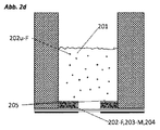
従って、本発明は、未結合の発光マーカーの発光を測定することにより生物学的検体を分析するためのデバイス[0]であって、結合した発光マーカーと未結合の発光マーカーとが水溶液中で1つ以上の機能化された表面の使用下に空間的および光学的に互いに離れているデバイスにも関し、その際、前記デバイスは分離のために少なくとも部分的に透光性である構造要素を有し、前記デバイスの基部は前記構造要素の底面を除いて非透光性であり、かつ前記水溶液は少なくとも1種類の生物学的検体および少なくとも1種類の発光マーカーを含有し、前記少なくとも1種類の生物学的検体および任意に少なくとも1種類の発光マーカーは1つ以上の機能化された表面に結合する。 Accordingly, the present invention provides a device [0] for analyzing a biological specimen by measuring the luminescence of an unbound luminescent marker, wherein the bound luminescent marker and the unbound luminescent marker are contained in an aqueous solution. The invention also relates to a device which is spatially and optically separated from one another by the use of one or more functionalized surfaces, the device comprising a structural element which is at least partially translucent for separation. Wherein the base of the device is non-translucent except at the bottom of the structural element, and wherein the aqueous solution contains at least one biological specimen and at least one luminescent marker; The biological sample and optionally at least one luminescent marker bind to one or more functionalized surfaces.
さらに、本発明は、本発明による方法において使用するための測定チャンバに関し、前記測定チャンバ内で、機能化された磁性粒子が使用される。結合した発光マーカー、好ましくは結合した蛍光マーカーと、未結合の発光マーカー、好ましくは未結合の蛍光マーカーとの分離は、測定チャンバの下方に配置された非透光性の磁性要素を用いた配向的な沈降により行われる。この磁性要素は空所を有し、該空所は、測定チャンバの底部(基部)に測定窓が生じるように配置されている。この磁性要素は基部に固定されていることができるか、または取り外し可能である。測定チャンバは構造要素を有していない。 Furthermore, the invention relates to a measuring chamber for use in the method according to the invention, wherein functionalized magnetic particles are used in said measuring chamber. Separation of the bound, preferably bound, fluorescent marker from the unbound, preferably unbound, fluorescent marker is achieved using an orientation using a non-translucent magnetic element located below the measurement chamber. This is done by sedimentation. The magnetic element has a cavity, which is arranged such that a measuring window is created at the bottom (base) of the measuring chamber. This magnetic element can be fixed to the base or can be removable. The measuring chamber has no structural elements.
機能化された磁性粒子の沈降は、測定窓の上方に粒子が沈殿しないように磁場により操作される。発光、好ましくは蛍光の測定は、測定チャンバの底部で測定窓を通じて蛍光測定装置を用いて測定することにより行われる。 The sedimentation of the functionalized magnetic particles is manipulated by a magnetic field so that the particles do not settle above the measuring window. The measurement of luminescence, preferably fluorescence, is performed by measuring with a fluorimeter at the bottom of the measurement chamber through a measurement window.
本発明はさらに、上記の測定チャンバ、またはそのような測定チャンバを少なくとも1つ具備したマイクロタイタープレートの、本発明による方法における使用に関し、その際、同様に機能性磁性粒子が使用される。 The invention furthermore relates to the use of a measuring chamber as described above, or a microtiter plate comprising at least one such measuring chamber, in a method according to the invention, wherein functional magnetic particles are likewise used.
本発明によるデバイス[0]の一実施形態[A]においては、1つ以上の機能化された表面が機能化された粒子として本発明によるデバイスに導入され、その際、結合した発光マーカーは該デバイスの分離除去領域内に存在し、未結合の発光マーカーは検出領域内に存在し、その際、該未結合の発光マーカーは好ましくは均一に分配されている。 In one embodiment [A] of the device [0] according to the present invention, one or more functionalized surfaces are introduced into the device according to the present invention as functionalized particles, wherein the bound luminescent marker is The unbound luminescent marker present in the separation area of the device is present in the detection area, wherein the unbound luminescent marker is preferably evenly distributed.
本発明によるデバイス[0]の一実施形態[B]においては、該デバイスの内側には、1つ以上の機能化された表面が、好ましくは基部とは反対側の構造要素端部の下方に存在する領域内に、好ましくは該デバイスの基部に存在する領域内に、存在する。分離は、生物学的検体と、発光マーカーと、デバイス内に存在し任意に固定化された1つ以上の機能化された表面との結合により行われる。 In one embodiment [B] of the device [0] according to the invention, one or more functionalized surfaces are present inside the device, preferably below the end of the structural element opposite the base. Present in the region present, preferably in the region present at the base of the device. Separation is achieved by the binding of a biological analyte, a luminescent marker, and one or more functionalized surfaces optionally present and immobilized within the device.
もう1つの実施形態[C]においては、本発明は、上記のまたは実施形態[A]もしくは[B]に記載したデバイスに関し、その際、構造要素が突出部として(好ましくは上方に向かって先細状の突出部として)構成されており、前記突出部の横断面は任意の形状を有することができ(例えば、円形、矩形、三角形)、前記デバイスの基部とは反対側の構造要素端部は、前記端部に試験成分、特に粒子が堆積しない状態にある。この端部は例えば平坦であってもよいし凸状形態をとっていてもよく、かつ/または小さい直径を有することができる。 In another embodiment [C], the invention relates to a device as described above or according to embodiment [A] or [B], wherein the structural elements are tapered as projections (preferably upwards). And the cross section of the protrusion can have any shape (e.g., circular, rectangular, triangular), and the structural element end opposite the base of the device is The test components, in particular the particles, are not deposited on the ends. This end may for example be flat or convex, and / or have a small diameter.
測定チャンバ内に存在する構造要素は、ピン、円錐、円錐台、底面がn角形である角錐または角錐台の形態を有することができ、その際、nは3〜10の範囲内の整数を表し、好ましくは3、4、5、6、7または8を表す。この構造要素はさらに、円錐または角錐から誘導される形態、例えば円形の土台上の円錐、または正方形の土台上の四面体の角錐を有することができる。 The structural elements present in the measuring chamber can have the form of a pin, a cone, a truncated cone, a pyramid or a truncated pyramid whose base is n-gonal, where n represents an integer in the range 3-10. , Preferably 3, 4, 5, 6, 7 or 8. The structural element can further have a form derived from a cone or pyramid, for example a cone on a circular base, or a tetrahedral pyramid on a square base.
構造要素はさらに、デバイスの基部とは反対側の端部に、光学部品、例えばレンズを有することができる。 The structural element can further have an optical component, for example a lens, at the end opposite the base of the device.
この構造要素は透光性である。この構造要素は、適した透光性の材料または材料混合物からなる。この材料が測定を妨害する自己蛍光を示さないことが重要である。透光性の材料は知られており、当業者により容易に選択されることができる。そのような材料は、例えばポリスチレン、COC(環状オレフィン共重合体)、ポリプロピレンまたはポリメチルメタクリレート(PMMA)である。極めて適しているのはポリプロピレンおよびPMMAである。ポリスチレンは特に高温加工時にある程度の自己蛍光を示すため(Young et al,Anal Chem.2013 January 2;85(1):44−49)、本発明によれば好ましくない。 This structural element is translucent. This structural element is made of a suitable translucent material or material mixture. It is important that this material does not show autofluorescence that would interfere with the measurement. Translucent materials are known and can be easily selected by those skilled in the art. Such materials are, for example, polystyrene, COC (cyclic olefin copolymer), polypropylene or polymethyl methacrylate (PMMA). Highly suitable are polypropylene and PMMA. Polystyrene is not preferred according to the present invention because it exhibits some degree of autofluorescence, especially during high-temperature processing (Young et al, Anal Chem. 2013 January 2: 85 (1): 44-49).
こうした材料または材料混合物を、1mm以下の厚さ(層厚)で使用することができる。好ましい厚さは、以下の範囲内である:約0.05〜約0.5mm、約0.1〜約0.45mm、約0.15〜約0.4mm、約0.2〜約0.4mm、または約0.2〜約0.35mm。 Such materials or material mixtures can be used with a thickness (layer thickness) of 1 mm or less. Preferred thicknesses are in the following ranges: about 0.05 to about 0.5 mm, about 0.1 to about 0.45 mm, about 0.15 to about 0.4 mm, about 0.2 to about 0.4 mm. 4 mm, or about 0.2 to about 0.35 mm.
もう1つの実施形態[D]においては、本発明は、上記のまたは実施形態[A]、[B]もしくは[C]のうちの1つに記載したデバイスに関し、前記デバイス内には分離除去領域および測定領域(検出領域)が存在し、前記測定領域は、透光性の測定窓を有するかまたはそのようなものと光学的に接続されている。 In another embodiment [D], the present invention relates to a device as described above or according to one of the embodiments [A], [B] or [C], wherein the device comprises an isolated removal area. And a measurement area (detection area), wherein the measurement area has a translucent measurement window or is optically connected to such.
もう1つの実施形態[E]においては、本発明は、上記のまたは実施形態[A]、[B]、[C]もしくは[D]のうちの1つに記載したデバイスに関し、前記デバイス内では構造要素の基部が測定窓として構成されている。その場合、発光の測定は、発光測定装置、好ましくは蛍光測定装置を用いて行われる。励起および放射の検出は、該デバイスの下方で行われる。 In another embodiment [E], the present invention relates to a device as described above or according to one of embodiments [A], [B], [C] or [D], wherein said device comprises: The base of the structural element is configured as a measuring window. In that case, the measurement of luminescence is performed using a luminescence measuring device, preferably a fluorescence measuring device. Excitation and emission detection take place below the device.
デバイスまたは測定チャンバ内に存在する構造要素の基部と端部とが光学的に互いに接続されている場合には、該デバイスの基部からこちらへと放射される励起光が該構造要素を通じて検出領域に到達し、該検出領域において未結合の発光マーカー、好ましくは未結合の蛍光マーカーを励起させて放射を生じさせ、次いで該放射が同様に該デバイスの基部から測定される。その場合、構造要素の端部が基部と共に測定窓を形成する。適した構造要素形状を選択する際には、励起光および放射光が粒子により妨害されないように留意すべきである。従って、構造要素の端部が凸状形態をとり、かつ該構造要素が上方に向かって先細状の突出部として構成されていることが特に好ましい。端部が平坦である場合には、該平坦部が小さく、かつ/または、該平坦部に粒子が堆積することができないかまたは妨害とならない数の粒子しか堆積することができない(本明細書中では「実質的に粒子が堆積することができない」とも称される)状態にあることが好ましい。端部が平坦である場合であっても、突出部が、基部とは反対側の該端部に向かって先細状であることが好ましい。 If the base and the end of the structural element present in the device or the measuring chamber are optically connected to each other, the excitation light emitted here from the base of the device to the detection area through the structural element Upon reaching, the unbound luminescent marker, preferably unbound fluorescent marker, is excited in the detection area to produce radiation, which is then measured from the base of the device as well. In that case, the ends of the structural element together with the base form a measuring window. Care should be taken in selecting a suitable structural element shape so that the excitation and emission light are not disturbed by the particles. It is therefore particularly preferred that the end of the structural element has a convex shape, and that the structural element is configured as an upwardly tapering projection. If the edges are flat, the flats are small and / or only a number of particles on which no or no obstructing particles can be deposited (as used herein). In this case, it is also referred to as “substantially no particles can be deposited”). Even when the end is flat, it is preferred that the protrusion be tapered toward the end opposite the base.
もう1つの実施形態[F]においては、本発明は、マイクロタイタープレートであって、前記マイクロタイタープレートの窪み、カップまたは凹部内に、それぞれ上記のまたは実施形態[0]、[A]、[B]、[C]、[D]もしくは[E]のうちの1つに記載したデバイスが組み込まれている前記マイクロタイタープレートに関する。 In another embodiment [F], the present invention relates to a microtiter plate, wherein said microtiter plate has a recess, cup or recess as described above or embodiments [0], [A], [A], respectively. B], [C], [D] or [E], wherein the microtiter plate incorporates the device.
相応して、一実施形態[F−1]においては、本発明は、本発明による方法を実施するためのマイクロタイタープレートであって、前記マイクロタイタープレートの少なくとも1つの凹部内にデバイスが導入されており、前記デバイスは少なくとも部分的に透光性である構造要素を有し、前記構造要素は上方に向かって先細状の突出部として構成されており、かつ該突出部の横断面は任意の形状を有することができ、基部とは反対側の構造要素端部は該端部に実質的に試験成分が堆積しない状態にあり、かつ前記デバイスの基部は前記構造要素の底面を除いて非透光性であり、かつ前記凹部の縁部が測定チャンバの側縁部を形成することを特徴とする前記マイクロタイタープレートに関する。 Accordingly, in one embodiment [F-1], the invention relates to a microtiter plate for performing a method according to the invention, wherein a device is introduced into at least one recess of said microtiter plate. Wherein the device has a structural element that is at least partially translucent, the structural element being configured as an upwardly tapering protrusion, and the cross-section of the protrusion being optional. The structural element end opposite the base may be substantially free of test components deposited on the end, and the base of the device is opaque except for the bottom surface of the structural element. The present invention relates to the microtiter plate, wherein the microtiter plate is optical and an edge of the recess forms a side edge of a measurement chamber.
もう1つの実施形態[F−2]においては、本発明は、実施形態[F−1]に記載したマイクロタイタープレートであって、前記マイクロタイタープレートの元の底部が、構造要素を有する一体型の基部に置き換えられており、前記マイクロタイタープレートの各々の凹部の中に1つの構造要素が存在し、前記基部は前記構造要素の底面を除いて非透光性となるように被覆されていることを特徴とする前記マイクロタイタープレートに関する。 In another embodiment [F-2], the invention relates to the microtiter plate according to embodiment [F-1], wherein the original bottom of the microtiter plate has a structural element. Wherein there is one structural element in each recess of the microtiter plate and the base is coated so as to be non-translucent except for the bottom surface of the structural element The present invention relates to the microtiter plate.
この場合、基部は構造要素と同一の材料からなり、かつ、該基部を形成する材料の選択に関しては、該構造要素との関連で挙げた材料特性および層厚に関する基準が該当する。 In this case, the base is made of the same material as the structural element, and the selection of the material forming the base conforms to the criteria for material properties and layer thickness given in connection with the structural element.
本発明は、以下を含む、実施形態[F−2]として記載したマイクロタイタープレートの製造にも関する:
(x)マイクロタイタープレートの底部を、構造要素を有する基部に置き換えるステップであって、ここで、前記基部は、好ましくは前記マイクロタイタープレートウェル中に存在するのと同数の構造要素を有するものとするステップ;
(y)前記基部を前記マイクロタイタープレートと接続させるステップ;および
(z)前記基部の下面に非透光性の層を施与し、その際、前記構造要素の底面を空所にするステップ。
The present invention also relates to the manufacture of the microtiter plate described as embodiment [F-2], comprising:
(X) replacing the bottom of the microtiter plate with a base having structural elements, wherein the base preferably has the same number of structural elements as present in the microtiter plate wells Step to do;
(Y) connecting the base to the microtiter plate; and (z) applying a non-translucent layer to the underside of the base, leaving the bottom surface of the structural element empty.
基部とマイクロタイタープレートとの接続および非透光性の層の施与は、以下に同様の文脈において記載するように行われる。 The connection of the base to the microtiter plate and the application of the non-translucent layer are performed as described below in a similar context.
構造要素を有する一体型の基部は、成形法により、例えば射出成形法、付加製造法(例えば3D印刷法)または熱成形法(熱間成形法、深絞り法または真空成形法)により製造可能である。 The monolithic base with the structural elements can be manufactured by molding methods, for example by injection molding, additive manufacturing (eg 3D printing) or thermoforming (hot forming, deep drawing or vacuum forming). is there.
当然のことながら、マイクロタイタープレートのすべての凹部の中に1つの構造要素が存在しているわけではないこともありうる。同様に、マイクロタイタープレートの複数の凹部の中に異なって形成された複数の構造要素が存在することも可能である。従って、構造要素を有する1つの一体型の基部は、異なって形成された複数の構造要素を有することができる。 Of course, there may not be one structural element in every recess of the microtiter plate. Similarly, it is possible that there are a plurality of differently formed structural elements in a plurality of recesses of the microtiter plate. Thus, one integral base with structural elements can have a plurality of differently formed structural elements.
もう1つの実施形態[G]においては、本発明は、上記のまたは実施形態[0]、[A]、[B]、[C]、[D]もしくは[E]のうちの1つに記載したデバイスを含む測定チャンバに関する。 In another embodiment [G], the invention relates to one of the above or embodiments [0], [A], [B], [C], [D] or [E]. The invention relates to a measurement chamber containing a device.
もう1つの実施形態[H]においては、本発明は、上記のまたは実施形態[0]、[A]、[B]、[C]、[D]、[E]、[F]もしくは[G]のうちの1つに記載したデバイス、測定チャンバまたはマイクロタイタープレートの、未結合の発光マーカーの発光の測定により生物学的検体を定性的または定量的に分析するための、イムノアッセイ、特に直接イムノアッセイ、サンドイッチイムノアッセイ、競合イムノアッセイまたは二次イムノアッセイにおける使用に関し、その際、前記発光マーカーは、好ましくは蛍光マーカーである。 In another embodiment [H], the invention relates to the above or embodiments [0], [A], [B], [C], [D], [E], [F] or [G]. An immunoassay, in particular a direct immunoassay, for qualitatively or quantitatively analyzing a biological specimen by measuring the luminescence of an unbound luminescent marker of a device, measuring chamber or microtiter plate according to one of the preceding claims. , A sandwich immunoassay, a competitive immunoassay or a secondary immunoassay, wherein the luminescent marker is preferably a fluorescent marker.
上記の方法の他に、本発明はさらに、以下を含む、本発明によるデバイス、測定チャンバまたはマイクロタイタープレートを使用して、特に上記のまたは実施形態[0]、[A]、[B]、[C]、[D]、[E]、[F]もしくは[G]のうちの1つに記載したデバイス、測定チャンバまたはマイクロタイタープレートを使用して生物学的検体を定性的および/または定量的に分析するための方法に関する:
(a)少なくとも1種類の機能化された表面をデバイスに導入するステップ;
(b)少なくとも1種類の生物学的検体を含有するサンプルを前記デバイスに導入するステップ;
(c)少なくとも1種類の発光マーカーを前記デバイスに導入するステップ;
(d)未結合の発光マーカーの発光放射を測定するステップ;および
(e)前記生物学的検体の量および/または濃度を分析するステップ。
In addition to the methods described above, the present invention further provides for the use of a device, measuring chamber or microtiter plate according to the present invention, particularly including the above or embodiments [0], [A], [B], comprising: Qualitative and / or quantitative determination of biological specimens using a device, measurement chamber or microtiter plate according to one of [C], [D], [E], [F] or [G] Regarding the method for analyzing statistically:
(A) introducing at least one functionalized surface into the device;
(B) introducing a sample containing at least one biological analyte into the device;
(C) introducing at least one luminescent marker into the device;
(D) measuring the luminescent emission of the unbound luminescent marker; and (e) analyzing the amount and / or concentration of said biological sample.
本発明による機能化された表面は、デバイス中にすでに存在することができるか、または本発明による方法において単独でもしくは測定溶液(サンプル)と一緒にデバイスに導入される。 The functionalized surface according to the invention can already be present in the device, or is introduced into the device alone or together with the measuring solution (sample) in the method according to the invention.
本発明のもう1つの実施形態においては、機能化された表面として、機能化された粒子が使用される。 In another embodiment of the present invention, functionalized particles are used as the functionalized surface.
本発明による方法においては、複数の種類の機能化された表面/粒子上に、または1つの表面/粒子表面上に、複数の種類の機能化が存在することができる。すなわち、表面の機能化の種類は異なっていてよい。その結果、本発明による方法を用いて、および本発明によるデバイスおよび測定チャンバにおいて、または本発明によるマイクロタイタープレートを用いて、複数の種類の生物学的検体を測定することができる。そのためには、各々の検体に対して、異なる波長で励起するおよび/または放射する固有の1つの発光マーカーを使用しなければならない。 In the method according to the invention, there can be more than one type of functionalization on more than one type of functionalized surface / particle or on one surface / particle surface. That is, the type of surface functionalization may be different. As a result, multiple types of biological specimens can be measured using the method according to the invention and in the device and the measurement chamber according to the invention or using the microtiter plate according to the invention. This requires the use of one unique luminescent marker that excites and / or emits at a different wavelength for each analyte.
機能化された磁性粒子を使用する場合にも、上記のことが同様に該当する。 The same applies to the use of functionalized magnetic particles.
「機能化された」という概念は、本発明に関連して、表面上に、好ましくは粒子表面上にスカベンジャー分子(以下、スカベンジャーとも称される)が存在することを意味する。表面または粒子表面の機能化のために、表面は少なくとも1種類のスカベンジャー分子で覆われる。スカベンジャー分子とは、1つ以上の生物学的検体とおよび/または1つ以上の発光マーカーと物理的または化学的に結合する分子をいう。その際、磁性粒子であるか非磁性粒子であるかということは、重要ではない。どちらの種類の粒子とも、本明細書中に記載したとおりに機能化されることができる。 The term “functionalized” in the context of the present invention means the presence of scavenger molecules (hereinafter also referred to as scavengers) on the surface, preferably on the particle surface. For functionalization of the surface or particle surface, the surface is covered with at least one scavenger molecule. A scavenger molecule refers to a molecule that physically or chemically binds to one or more biological analytes and / or to one or more luminescent markers. At that time, it does not matter whether the particles are magnetic particles or non-magnetic particles. Either type of particle can be functionalized as described herein.
本発明によれば、「機能化された」とは、固定化金属アフィニティークロマトグラフィー(IMAC)に関連して以下に説明するように、磁性粒子または非磁性粒子が適切な金属イオンで覆われていることをも意味するため、本明細書中では、形成される金属イオン錯体(例えば、NTA−Ni2+)がスカベンジャー分子を形成し、その後で該スカベンジャー分子が相応するタグを有する試験成分と結合する。 According to the present invention, "functionalized" means that magnetic or non-magnetic particles are covered with a suitable metal ion, as described below in connection with immobilized metal affinity chromatography (IMAC). In this context, the metal ion complex formed (e.g., NTA-Ni2 + ) forms a scavenger molecule, which then binds to a test component having a corresponding tag. I do.
競合アッセイに関しては、機能化された表面、特に粒子表面がスカベンジャーを有し、該スカベンジャーに、生物学的検体と発光マーカーとが同一の結合部位で物理的および/または化学的に結合しうることが必要である。他のアッセイに関しては、スカベンジャーが1つ以上の生物学的検体のみと結合するか、または所望の場合には1つ以上の発光マーカー、好ましくは蛍光マーカーと結合する状態にあることが望ましい。 For a competition assay, the functionalized surface, especially the particle surface, has a scavenger to which the biological analyte and the luminescent marker can physically and / or chemically bind at the same binding site. is necessary. For other assays, it is desirable that the scavenger bind only to one or more biological analytes, or if desired, to one or more luminescent markers, preferably fluorescent markers.
機能化された磁性粒子が使用される場合にも、同様のことが該当する。 The same applies when functionalized magnetic particles are used.
機能化の一変形においては、スカベンジャー分子は1種類の生物学的検体に関して特異的に選択された結合部位のみを有し、一方で他の一変形においては、スカベンジャー分子は複数の異なる結合部位を有し、その際、各々の結合部位は、該結合部位が特定の1つの生物学的検体のみと結合するように選択されている。該変形により、機能化された表面に異なる種類の生物学的検体が結合することが可能である。 In one variation of the functionalization, the scavenger molecule has only binding sites specifically selected for one type of biological specimen, while in another variation, the scavenger molecule has multiple different binding sites. Wherein each binding site is selected such that the binding site only binds to one particular biological analyte. The variant allows different types of biological analytes to bind to the functionalized surface.
異なる種類の生物学的検体を同時に測定することが望ましい場合には、本発明による方法において、機能化された異なる(磁性)粒子を1つの測定チャンバ内で使用することもできる。 If it is desired to measure different types of biological specimens simultaneously, functionalized different (magnetic) particles can also be used in one measuring chamber in the method according to the invention.
機能化の一変形には、表面に異なる種類のスカベンジャー分子を具備させることが含まれ、その際、該スカベンジャー分子の各々は、分析すべき生物学的検体のための少なくとも1つの結合部位を有する。 One variation of functionalization involves providing the surface with different types of scavenger molecules, each of which has at least one binding site for a biological analyte to be analyzed. .
本発明による方法において、複数の種類の生物学的検体と結合しうる機能化された粒子または機能化された磁性粒子が使用される場合には、各々の検体に対して、異なる波長で励起するおよび/または放射する固有の1つの発光マーカー、好ましくは蛍光マーカーを使用しなければならない。 In the method according to the present invention, when functionalized particles or functionalized magnetic particles capable of binding to a plurality of types of biological analytes are used, each analyte is excited at a different wavelength. A unique luminescent marker, preferably a fluorescent marker, that emits and / or emits must be used.
本発明による方法を確実に実施するためには、特に直接(イムノ)アッセイ、サンドイッチ(イムノ)アッセイまたは二次(イムノ)アッセイの場合には、スカベンジャー分子、さらに表面または粒子表面が、1つ以上の生物学的検体以外の試験成分と特異的または非特異的に結合することが重要である。これに対する例外は、競合(イムノ)アッセイおよび置換アッセイである。競合(イムノ)アッセイでは、スカベンジャーは同一の結合部位において発光マーカーおよび特異的な生物学的検体と結合することができる。置換アッセイでは、スカベンジャーは発光マーカー、好ましくは蛍光マーカーと結合する。 In order to ensure that the method according to the invention is carried out, in particular in the case of a direct (immuno) assay, a sandwich (immuno) assay or a secondary (immuno) assay, the scavenger molecule and also the surface or the particle surface are one or more. It is important to bind specifically or non-specifically to test components other than the biological sample. Exceptions to this are competition (immuno) and displacement assays. In a competition (immuno) assay, the scavenger can bind to a luminescent marker and a specific biological analyte at the same binding site. In displacement assays, the scavenger binds to a luminescent marker, preferably a fluorescent marker.
表面および粒子表面の機能化に適したスカベンジャーは知られており、該スカベンジャーは、1つ以上の所望の試験成分が該スカベンジャーに結合するように選択される。適切なスカベンジャーは主にタンパク質(例えば抗体)であり、該タンパク質は必要に応じてリンカー系を用いて表面または粒子表面に結合される。表面または粒子表面のスカベンジャーでの被覆は、共有結合により行われてもよいし非共有結合により行われてもよい。試験成分のうちの1つ(例えば生物学的検体)が抗体である場合には、スカベンジャーは通常はタンパク質である。抗体に対する知られているスカベンジャーは、例えば黄色ブドウ球菌からのプロテインAおよびレンサ球菌からのプロテインGである。 Scavengers suitable for surface and particle surface functionalization are known, and the scavenger is selected such that one or more desired test components bind to the scavenger. Suitable scavengers are predominantly proteins (eg antibodies), which are attached to the surface or particle surface, optionally using a linker system. The coating of the surface or particle surface with a scavenger may be effected covalently or non-covalently. If one of the test components (eg, a biological specimen) is an antibody, the scavenger is usually a protein. Known scavengers for antibodies are, for example, Protein A from Staphylococcus aureus and Protein G from Streptococcus.
機能化された磁性粒子が使用される場合にも、同様のことが該当する。 The same applies when functionalized magnetic particles are used.
リンカー系を具備した表面の例は、以下に詳細に記載するように、ストレプトアビジンで被覆された粒子であり、例えばストレプトアビジン Mag−Sepharose(登録商標)粒子(VWR、品番28−9857−38)である。もう1つの例は、表面上にニトリロ酢酸基(NTA)またはイミノ酢酸基(IDA)を有するアガロース粒子であり、該基は金属イオンと極めて安定な錯体を形成し、いわゆるHisタグで標識されたタンパク質の結合に適している。 Examples of surfaces provided with a linker system are streptavidin-coated particles, such as streptavidin Mag-Sepharose® particles (VWR, part number 28-9857-38), as described in detail below. It is. Another example is agarose particles having nitriloacetic acid groups (NTA) or iminoacetic acid groups (IDA) on the surface, which form a very stable complex with metal ions and are labeled with a so-called His tag. Suitable for binding proteins.
機能化された粒子の製造に適しておりかつ多孔質材料からなる慣用の材料の一つにアガロースがあり、これはSepharose(登録商標)(GE Healthcare)の名称で市販されている。Sepharoseまたはアガロースは、様々な架橋度で、また様々な結合能で入手可能である。機能化の前に、すなわちスカベンジャー分子での被覆の前に、化学薬品でアガロース粒子を活性化させることにより、スカベンジャー分子との効率的な結合が保証される。活性化に適した化学薬品は、CNBrである。 One conventional material suitable for the production of functionalized particles and consisting of a porous material is agarose, which is commercially available under the name Sepharose® (GE Healthcare). Sepharose or agarose is available with varying degrees of cross-linking and with varying binding capacities. Activating the agarose particles with a chemical before functionalization, ie before coating with the scavenger molecule, ensures efficient binding to the scavenger molecule. A suitable chemical for activation is CNBr.
すでに説明したように、慣用のスカベンジャー分子はタンパク質である。タンパク質を表面に、特に粒子表面に結合させるために、該表面とスカベンジャー分子との間のリンカーとして作用する化学薬品(例えばストレプトアビジンまたはそのホモログ(例えばアビジン、ニュートラアビジン))を使用することができる。ストレプトアビジンまたはそのホモログはビオチンと安定な結合を生じ、それにより、ビオチン化プロテインAの各々が、ストレプトアビジンで処理された(粒子)表面と結合する。機能化された磁性粒子が使用される場合にも、同様のことが該当する。 As already explained, conventional scavenger molecules are proteins. To bind the protein to the surface, especially to the particle surface, a chemical (eg, streptavidin or a homolog thereof (eg, avidin, neutravidin)) that acts as a linker between the surface and the scavenger molecule can be used. . Streptavidin or a homolog thereof forms a stable bond with biotin, whereby each of the biotinylated protein A binds to the streptavidin-treated (particle) surface. The same applies when functionalized magnetic particles are used.
タンパク質のビオチン化は知られており、生化学における標準的な手法の一つである。通常、ビオチン化には活性エステル(例えば、NHS、N−ヒドロキシスクシンイミド)が利用され、該活性エステルによりビオチンがスカベンジャータンパク質の遊離アミノ官能基に結合される。ビオチン化スカベンジャータンパク質は、通常は、ストレプトアビジンでまたはそのホモログで処理された(磁性)粒子に結合される。 Biotinylation of proteins is known and is one of the standard techniques in biochemistry. Typically, biotinylation utilizes an active ester (e.g., NHS, N-hydroxysuccinimide), which couples biotin to a free amino function of a scavenger protein. Biotinylated scavenger proteins are usually bound to (magnetic) particles that have been treated with streptavidin or a homolog thereof.
タンパク質親和性タグを含むスカベンジャータンパク質は、金属錯体を介して(粒子)表面に結合されることができる。これには実質的には、所定のアミノ酸が適切な金属イオン(例えば、Co2+、Ni2+、Cu2+およびZn2+)と安定な錯体を形成するという原理が用いられる。そのようなアミノ酸は、タンパク質中に天然に存在することもできるし、ポリペプチドとしてタンパク質にいわゆる「タグ」として導入されていてもよい。慣用のタグは、Argタグ、c−Mycタグ、FlagタグおよびHisタグである。金属イオンは、NTA(ニトリロ酢酸)、CMA(カルボキシメチルアスパラギン酸)またはIDA(イミノ酢酸)を用いて(粒子)表面に結合される。実質的には、上記の機能化の際には、その他ではタンパク質のクロマトグラフィー精製の際に、特に固定化金属アフィニティークロマトグラフィー(IMAC)の際に使用されるのと同一の原理が利用される。 Scavenger proteins containing a protein affinity tag can be bound to the (particle) surface via a metal complex. This essentially uses the principle that a given amino acid forms a stable complex with the appropriate metal ion (eg, Co 2+ , Ni 2+ , Cu 2+ and Zn 2+ ). Such amino acids can occur naturally in the protein, or have been introduced as a polypeptide into the protein as a so-called “tag”. Conventional tags are Arg tag, c-Myc tag, Flag tag and His tag. The metal ions are bound to the (particle) surface using NTA (nitriloacetic acid), CMA (carboxymethylaspartic acid) or IDA (iminoacetic acid). Substantially the same principles are used in the above functionalization as in the other chromatographic purification of proteins, in particular in immobilized metal affinity chromatography (IMAC). .
上記の原理を利用することにより、機能化された(磁性)粒子を、使用すべきアッセイに、または分析すべき1つ以上の生物学的検体に個々に適合させることができ、それによって、当業者は本発明による方法を自身のそれぞれの要求に容易に適合させることができる。 By utilizing the above principles, the functionalized (magnetic) particles can be individually adapted to the assay to be used or to one or more biological analytes to be analyzed, thereby The person skilled in the art can easily adapt the method according to the invention to his own requirements.
機能化された表面がデバイス内にすでに存在する場合には、本発明は、もう1つの実施形態において、機能化された表面のデバイスへの導入、すなわちステップ(a)を、ステップ(a’)として行うことに関し、すなわち、前記デバイス内の少なくとも1つの表面、好ましくは前記デバイスの基部を処理し、その際、前記基部とは反対側の構造要素端部には処理を行わないものとし、ここで、前記処理とは、スカベンジャーと前記基部を支援するコーティング緩衝液とを結合させるための処理であるものとし、かつ少なくとも1種類のスカベンジャーを添加し、その際、前記スカベンジャーを好ましくは溶解させて添加するものとする。 If the functionalized surface is already present in the device, the invention, in another embodiment, introduces the functionalized surface into the device, i.e., step (a), step (a ') That is, treating at least one surface within the device, preferably the base of the device, without treating the end of the structural element opposite the base, In the above, the treatment is a treatment for binding a scavenger and a coating buffer that supports the base, and at least one scavenger is added, wherein the scavenger is preferably dissolved. Shall be added.
従って、本発明は、デバイス、本発明による測定チャンバおよび本発明によるマイクロタイタープレートであって、前記デバイスの少なくとも1つの表面、好ましくは前記デバイスの基部は機能化されており、前記基部とは反対側の構造要素端部は機能化されていない、前記デバイス、本発明による測定チャンバおよび本発明によるマイクロタイタープレートにも関する。処理されたデバイス表面は、本明細書中では「定置」表面とも称される。 Thus, the present invention relates to a device, a measuring chamber according to the invention and a microtiter plate according to the invention, wherein at least one surface of said device, preferably the base of said device, is functionalized and opposite to said base. The side structural element ends also relate to the device, the measuring chamber according to the invention and the microtiter plate according to the invention, which are not functionalized. The treated device surface is also referred to herein as a "stationary" surface.
スカベンジャーを添加した後、機能化が予定される所望の箇所にコーティング緩衝液を数時間または一晩作用させることが有利である。スカベンジャー分子での表面の被覆に適したコーティング緩衝液は知られている。この例は塩基性の炭酸塩緩衝液であり、これにより、例えばスカベンジャー分子であるプロテインAを所望の部位に、例えばデバイスの基部に結合させることができる。 After adding the scavenger, it is advantageous to allow the coating buffer to act for several hours or overnight at the desired location where functionalization is expected. Coating buffers suitable for coating surfaces with scavenger molecules are known. An example of this is a basic carbonate buffer, which allows, for example, binding of the scavenger molecule protein A to a desired site, for example to the base of the device.
同様に、デバイス、本発明による測定チャンバおよび本発明によるマイクロタイタープレートの基部をストレプトアビジンにより機能化することができ、それにより、予めそれぞれビオチン基が付与(標識)されている複数の異なるスカベンジャーが、所望の部位に結合される。 Similarly, the device, the measuring chamber according to the invention and the base of the microtiter plate according to the invention can be functionalized with streptavidin, so that a plurality of different scavengers, each of which is pre-labeled (labeled) with a biotin group, respectively. At the desired site.
機能化された適切な表面を選択することにより、試験時間に影響を与えることができる。原則的には、機能化された大表面によって、測定すべき1つ以上の生物学的検体が、また所望であって予定される場合には1つ以上の発光マーカーが、拡散によりスカベンジャーと出会う可能性が高まる。測定の速度は、適切な表面サイズ、ならびに該表面上に存在するスカベンジャーの種類および数の選択に影響を受けうる。本発明による方法を迅速化するためには、好ましくは、大表面であって該表面上に複数のスカベンジャーが存在する表面が使用される。このことは、粒子表面にも定置表面にも該当する。 By choosing an appropriate surface that has been functionalized, the test time can be affected. In principle, the functionalized large surface allows one or more biological analytes to be measured and, if desired and expected, one or more luminescent markers to encounter the scavenger by diffusion. The possibilities increase. The speed of the measurement can be influenced by the choice of the appropriate surface size and the type and number of scavengers present on the surface. In order to speed up the method according to the invention, preferably a large surface is used, on which a plurality of scavengers are present. This applies to both particle surfaces and stationary surfaces.
本発明による方法の速度に影響を与えるもう1つの要因としては、使用される機能化された表面のサイズの他に、該表面の結合能が挙げられる。機能化された粒子の場合、該粒子の結合能とは、該機能化された粒子に所定量の生物学的検体を結合させる能力であって、該存在する機能化された粒子の量または重量、質量に関する能力を指す。本発明による方法において速度を決定づけるもう1つのパラメータは、以下に詳説するように、試験成分の入念な混合である。その際、磁性粒子であるか非磁性粒子であるかということは、重要ではない。 Another factor affecting the speed of the method according to the invention is the size of the functionalized surface used, as well as the binding capacity of said surface. In the case of a functionalized particle, the binding capacity of the particle is the ability to bind a predetermined amount of a biological analyte to the functionalized particle, and the amount or weight of the functionalized particle present. , Refers to the ability with respect to mass. Another parameter that determines the speed in the method according to the invention is the elaborate mixing of the test components, as detailed below. At that time, it does not matter whether the particles are magnetic particles or non-magnetic particles.
本発明による方法において機能化された表面として使用することができる機能化された(磁性)粒子は、市販されているかまたは本方法のために相応して個別に製造される。 Functionalized (magnetic) particles which can be used as functionalized surfaces in the process according to the invention are commercially available or correspondingly prepared individually for the process.
そのような個別に機能化された粒子を製造するために、特に合成または天然のポリマー、例えばポリスチレン、ラテックス、アガロース、ポリラクチドまたはPMMAならびに多糖類からの粒子を使用することができる。多孔性材料、例えばアガロースからの粒子が好ましい。特に適しているのは、生物学的検体の、例えばタンパク質のクロマトグラフィー精製に使用される市販の粒子である。この粒子は、通常はスラリーとして提供されている。上記のことは磁性粒子にも同様に該当し、その際、合成または天然のポリマーが磁性コアを包囲している。 In order to produce such individually functionalized particles, in particular particles from synthetic or natural polymers such as polystyrene, latex, agarose, polylactide or PMMA and polysaccharides can be used. Particles from a porous material such as agarose are preferred. Particularly suitable are commercially available particles used for the chromatographic purification of biological specimens, for example proteins. The particles are usually provided as a slurry. The above applies equally to magnetic particles, wherein a synthetic or natural polymer surrounds the magnetic core.
本発明により使用することができる非磁性粒子は、しばしば球状粒子であり、約0.1〜約200μmの範囲内の典型的な平均直径を有する。本発明により好ましい粒子は、約20〜約200μmの範囲内、特に約80〜約200μmの範囲内の平均直径を有し、かつ試験成分との非特異的な結合を生じない。本発明によれば、IgGまたは検体1mL当たり20mgを上回る結合能を有する粒子が好ましい。 Non-magnetic particles that can be used in accordance with the present invention are often spherical particles, having a typical average diameter in the range of about 0.1 to about 200 μm. Particles preferred according to the invention have an average diameter in the range of about 20 to about 200 μm, especially in the range of about 80 to about 200 μm, and do not cause non-specific binding to the test component. According to the invention, particles having a binding capacity of more than 20 mg per ml of IgG or analyte are preferred.
本発明により使用することができる磁性粒子(「磁性ビーズ」とも称される)は、通常は生物学的検体の単離または分析に使用されるものである(例えばWO2006/112771参照)。磁性粒子のポリマーコーティングは、通常は、糖、ポリビニルアルコールまたはケイ酸塩からなる。磁性粒子は、粒子に関して説明した方法と同様の方法で機能化することができるか、またはすでに機能化された磁性粒子として市販されている(例えば、GE HealthcareのプロテインA Mag−Sepharose(登録商標)粒子、品番28−9440−06)。本発明により特に適した磁性粒子は、多孔性材料、例えばアガロースからのコーティングを有し、かつフェライトまたはマグネタイトからのコアを有する(例えばMag−Sepharose(登録商標)粒子)。 The magnetic particles (also referred to as “magnetic beads”) that can be used according to the invention are those normally used for the isolation or analysis of biological specimens (see, for example, WO 2006/112771). The polymer coating of the magnetic particles usually consists of sugar, polyvinyl alcohol or silicate. Magnetic particles can be functionalized in a manner similar to that described for the particles, or are commercially available as already functionalized magnetic particles (eg, Protein A Mag-Sepharose® from GE Healthcare). Particles, part number 28-9440-06). Magnetic particles particularly suitable according to the invention have a coating from a porous material, for example agarose, and have a core from ferrite or magnetite (for example Mag-Sepharose® particles).
磁性粒子も同様に球状粒子であり、約1〜約100μmの範囲内の典型的な平均直径を有する。 Magnetic particles are likewise spherical particles and have a typical average diameter in the range of about 1 to about 100 μm.
当業者は、分析される生物学的検体と組み合わせて使用することができる機能化された磁性または非磁性の粒子を容易に見出すことができ、かつ、部分的にそのような組み合わせは従来技術のさらに発展したイムノアッセイ法においてすでに使用されている。 One of skill in the art can readily find functionalized magnetic or non-magnetic particles that can be used in combination with the biological specimen being analyzed, and in part such combinations are known in the art. It is already used in more advanced immunoassays.
以下の記載は、機能化された磁性粒子が使用される場合にも該当する。 The following description also applies when functionalized magnetic particles are used.
ステップ(a)(場合により(a’))、(b)および(c)は、本発明による方法において、連続して、すなわち逐次的に行われてもよいし、ステップ(a)、(b)および(c)の少なくとも2つを同時に行うこともでき、これを、例えばデバイス内に機能化された表面を装入し、次いでサンプルと発光マーカーとを含有する測定溶液を装入することにより行うことができる。またそれに代えて、検体を含有するサンプルが装入され、これに、発光マーカーと、機能化された粒子の形態の機能化された表面とが添加される。逐次的な添加の場合には、通常はステップの順序は重要ではない。ステップ(b)をステップ(a)および(c)の前に行うことも、ステップ(b)をステップ(c)および(a)の前に行うことも、ステップ(c)をステップ(a)または(b)の前に行うことも可能である。競合イムノアッセイの場合には、ステップ(b)とステップ(c)とを同時に行うことが好ましい。すでに機能化された表面を有するデバイスが使用される場合には、ステップ(a)は省かれる。 Steps (a) (possibly (a ′)), (b) and (c) may be performed in the method according to the invention in succession, ie sequentially, or in steps (a), (b) ) And (c) can also be performed simultaneously, for example by loading the functionalized surface in the device and then loading the measurement solution containing the sample and the luminescent marker. It can be carried out. Alternatively, a sample containing the analyte is loaded, to which the luminescent marker and the functionalized surface in the form of functionalized particles are added. In the case of sequential addition, the order of the steps is usually not important. Step (b) can be performed before steps (a) and (c), step (b) can be performed before steps (c) and (a), and step (c) can be performed in step (a) or It is also possible to perform before (b). In the case of a competitive immunoassay, it is preferable to perform step (b) and step (c) simultaneously. If a device having a surface that has already been functionalized is used, step (a) is omitted.
好ましくは、本発明による方法において、ステップ(a)およびステップ(c)は、その他の方法ステップの前に、同時にまたは逐次的に行われる。同様に好ましくは、ステップ(a)またはステップ(c)はその他の方法ステップの前に行われる。 Preferably, in the method according to the invention, steps (a) and (c) are performed simultaneously or sequentially before the other method steps. Also preferably, step (a) or step (c) is performed before the other method steps.
その際、ステップ(a)および/または(c)とその他の方法ステップとの時間的間隔は短くても長くてもよい(例えば、数時間、数日間、数週間、数カ月間または数年間)。この間隔が12時間を上回る場合には、ステップ(a)および/または(c)に導入される試験成分、すなわち導入された機能化された(磁性)粒子および/または蛍光マーカーが、測定チャンバ内で乾燥された状態にあることが好ましい。測定チャンバは、室温で、好ましくは最高で37℃、好ましくは35℃の高められた温度で乾燥される。乾燥期間は、通常は、測定チャンバに導入される水溶液の量に依存する。通常の乾燥時間は、12〜24時間の範囲内である。 The time interval between steps (a) and / or (c) and the other method steps may be short or long (eg, hours, days, weeks, months or years). If this interval is longer than 12 hours, the test components introduced in steps (a) and / or (c), ie the introduced functionalized (magnetic) particles and / or fluorescent markers, will Is preferably in a dried state. The measuring chamber is dried at room temperature, preferably at an elevated temperature of at most 37 ° C., preferably 35 ° C. The drying period usually depends on the amount of the aqueous solution introduced into the measuring chamber. Typical drying times are in the range of 12 to 24 hours.
乾燥前に、場合によりさらなる物質を測定チャンバに導入することができ、該物質は、(磁性)粒子および/または発光マーカーまたは蛍光マーカーの機能性/活性が乾燥後にそのまま維持されるためのものであることが望ましい。適当な物質は、BSA、糖または界面活性剤、例えばTween 20である。 Before drying, optionally further substances can be introduced into the measuring chamber, such that the functionality / activity of the (magnetic) particles and / or the luminescent or fluorescent markers is maintained after drying. Desirably. Suitable substances are BSA, sugars or surfactants, such as Tween 20.
従って、本発明は、本発明による測定チャンバおよびマイクロタイタープレートであって、
(i)少なくとも1種類の機能化された粒子もしくは機能化された磁性粒子、および少なくとも1種類の蛍光マーカー、または
(ii)少なくとも1種類の機能化された粒子もしくは機能化された磁性粒子、または
(iii)少なくとも1種類の蛍光マーカー
がそれぞれ乾燥状態にある本発明による測定チャンバおよびマイクロタイタープレート、ならびに本発明による方法におけるその使用にも関する。
Accordingly, the present invention provides a measurement chamber and a microtiter plate according to the present invention,
(I) at least one functionalized particle or functionalized magnetic particle and at least one fluorescent marker, or (ii) at least one functionalized particle or functionalized magnetic particle, or (Iii) It also relates to a measuring chamber and a microtiter plate according to the invention, wherein at least one fluorescent marker is in a dry state, respectively, and to its use in the method according to the invention.
同様に、本発明はその製造にも関する。このために上記のとおりの措置がとられ、すなわちこれは、相応する試験成分を本発明による測定チャンバへの導入後に乾燥または凍結乾燥させることにより行われる。 The invention likewise relates to its manufacture. For this purpose, measures are taken as described above, that is to say by drying or freeze-drying the corresponding test components after introduction into the measuring chamber according to the invention.
少なくとも1種類の機能化された粒子または機能化された磁性粒子および/または少なくとも1種類の蛍光マーカーがすでに乾燥状態にある測定チャンバが使用される場合には、本発明による方法においては、該当する試験成分を添加する1つ以上のステップは省かれる。例えば、機能化された(磁性)粒子がすでに乾燥状態にある場合には、機能化された(磁性)粒子の導入、すなわちステップ(a)は省かれる。 If a measuring chamber is used in which at least one functionalized particle or functionalized magnetic particle and / or at least one fluorescent marker is already in a dry state, the method according to the invention is not relevant. One or more steps of adding the test ingredients are omitted. For example, if the functionalized (magnetic) particles are already in a dry state, the introduction of the functionalized (magnetic) particles, ie step (a), is omitted.
本発明による方法においては試験成分間に結合が形成されるが、該結合は該試験成分同士の親和性およびその濃度に依存する。本発明による方法に関しては、未結合の発光マーカーの量が所与の一定の試験条件で生物学的検体の量のみに依存することが必要である。 In the method according to the invention, a bond is formed between the test components, which depends on the affinity of the test components and on their concentration. For the method according to the invention, it is necessary that the amount of unbound luminescent marker only depends on the amount of biological specimen at a given constant test condition.
本発明の一実施形態においては、様々な部位(エピトープ)で、発光マーカーおよびスカベンジャーと生物学的検体とがそれぞれ結合する(図6a、図6cおよび図7aに概略的に示す)。 In one embodiment of the invention, at various sites (epitope), the luminescent marker and the scavenger bind to the biological specimen, respectively (shown schematically in FIGS. 6a, 6c and 7a).
本発明のもう1つの実施形態においては、発光マーカーおよび生物学的検体がそれぞれスカベンジャー分子上の同一の部位に結合することができる(図6bに概略的に示す)。 In another embodiment of the invention, a luminescent marker and a biological analyte can each bind to the same site on the scavenger molecule (shown schematically in FIG. 6b).
本発明のもう1つの実施形態においては、生物学的検体に、発光マーカーに代えていわゆる「一次抗体」が結合し、該一次抗体に該発光マーカーが結合する(図7bに概略的に示す)。 In another embodiment of the present invention, a so-called "primary antibody" binds to a biological sample instead of a luminescent marker, and the luminescent marker binds to the primary antibody (shown schematically in FIG. 7b). .
結合の生成を加速させるためには、すべての試験成分を導入した後に該試験成分を本発明によるデバイス、測定チャンバまたはマイクロタイタープレート内で十分に混合することが合理的である。これは、手動で行われてもよいし自動で行われてもよい。試験成分の接触の速度が高いほど、平衡の達成、ひいては生物学的検体の測定/分析がより迅速に進行する。機能化された磁性粒子が使用される場合にも、同様のことが該当する。 In order to accelerate the formation of the bond, it is reasonable to mix all the test components in the device, the measuring chamber or the microtiter plate according to the invention after all the test components have been introduced. This may be done manually or automatically. The higher the rate of contact of the test components, the faster the equilibrium is achieved, and thus the measurement / analysis of the biological sample. The same applies when functionalized magnetic particles are used.
本方法がより迅速に行われることが望ましい場合には、平衡の達成を省くことができる。この場合には、全てのサンプルおよびキャリブレーターに関して同一のインキュベーション時間および条件を維持することが重要である。 If it is desired that the method be performed more quickly, achieving equilibrium can be omitted. In this case, it is important to maintain the same incubation times and conditions for all samples and calibrators.
混合を自動化するためには、本発明によるデバイスを中に有するユニット(例えば、測定チャンバまたはマイクロタイタープレート)を、実験室で常用されているシェーカー(振とう装置)に載置する。このような振とう装置は知られている。簡単な手法により、最適な振とう速度を見出すことができる。ボルテックス装置の使用も考えられる。混合の目的は、試験成分同士が衝突する確率を高めることで所望の結合を可能な限りスピーディーに形成させ、それにより該成分の結合の平衡達成を迅速に生じさせることにある。成分の結合の平衡達成に要する時間は可変であり、容易に見出すことができる。通常は、成分が測定に十分な結合の平衡に達するまでには、15〜30分間の範囲内の最適な完全混合時間を要する。 To automate the mixing, the unit with the device according to the invention (for example a measuring chamber or a microtiter plate) is placed on a shaker that is commonly used in the laboratory. Such shaking devices are known. With a simple method, the optimum shaking speed can be found. The use of a vortex device is also conceivable. The purpose of the mixing is to increase the probability of collision of the test components so that the desired bond is formed as quickly as possible, thereby causing a rapid equilibrium of the binding of the components. The time required to achieve equilibrium of the binding of the components is variable and can be easily found. Usually, it takes an optimal complete mixing time in the range of 15 to 30 minutes for the components to reach a binding equilibrium sufficient for the measurement.
(好ましくは機能化された粒子の形態の)機能化された表面がフルイディクス系またはマイクロフルイディクス系に導入された場合には、自由拡散または振とうに代えて、試験成分同士が衝突する確率を高めることができ、特に生物学的検体とスカベンジャー分子とが衝突する確率を高めることができる。これらの系内では、機能化された表面が分析すべき1つ以上の生物学的検体によって活発に押し流され、それにより該機能化された表面(好ましくは機能化された粒子)上での該1つ以上の生物学的検体の濃縮が生じる。マイクロフルイディクス系は、扱いにくいサンプル、例えばヒト血清における検出感度を高めるためにしばしば使用される。 If the functionalized surface (preferably in the form of functionalized particles) is introduced into a fluidics or microfluidics system, instead of free diffusion or shaking, the probability of the test components colliding with each other is reduced. And especially the probability of collision between the biological analyte and the scavenger molecule. Within these systems, the functionalized surface is actively swept away by one or more biological analytes to be analyzed, whereby the functionalized surface (preferably the functionalized particles) Enrichment of one or more biological analytes occurs. Microfluidics systems are often used to increase the sensitivity of detection in cumbersome samples, such as human serum.
本発明による発光マーカーは、所望の試験成分(特に1つ以上の生物学的検体)と結合し、それと同時に光を放射することができる。本発明によるデバイスにおいては、また本発明による方法においては、考えうるあらゆる発光マーカーを使用することができる。好ましくは、蛍光マーカーが使用される。 A luminescent marker according to the present invention can bind to a desired test component, in particular one or more biological analytes, and at the same time emit light. In the device according to the invention and in the method according to the invention, any conceivable luminescent marker can be used. Preferably, a fluorescent marker is used.
本発明の範囲においては、「結合した発光マーカー」という概念は、機能化された表面に、直接またはさらなる試験成分を介して(例えば検体または一次抗体を介して)結合している、あらゆる発光マーカーであると理解される。同時に、「未結合の」という概念は、機能化された表面に直接結合してもいないしさらなる試験成分を介して結合してもいない発光マーカーまたは蛍光マーカーを指す。 Within the scope of the present invention, the term “bound luminescent marker” refers to any luminescent marker bound to a functionalized surface, either directly or via a further test component (eg via an analyte or primary antibody). Is understood to be. At the same time, the term "unbound" refers to luminescent or fluorescent markers that are neither directly bound to the functionalized surface nor bound via additional test components.
所定の生物学的検体および/または機能化された表面に結合する発光マーカーまたは蛍光マーカーは知られており、市販されている。適しているのは、例えばAlexa 647標識抗体フラグメントまたはAlexa 488標識抗体フラグメント(例えば、Alexa 647 Conjugated AffiniPure F(ab’)2 Fragment Goat Anti−Human IgG F(ab’)2 specific、およびpolyclonal Rabbit Anti−Chicken IgY (H+L)−Alexa Fluor 488、Alexa 488 AffiniPure F(ab’)2 Fragment Goat Anti−Human IgG,F(ab’)2 specific)またはフルオレセイン−イソチオシアネート(FITC)Conjugated polyclonal Chicken Anti−Human IgG(H+L)抗体、およびR−フィコエリトリンAffiniPure F(ab’)2 Fragment Goat Anti−Human IgG,Fcγ Fragment specificである。 Luminescent or fluorescent markers that bind to a given biological analyte and / or functionalized surface are known and commercially available. Suitable are, for example, Alexa 647-labeled antibody fragments or Alexa 488 labeled antibody fragments (e.g., Alexa 647 Conjugated AffiniPure F (ab ') 2 Fragment Goat Anti-Human IgG F (ab') 2 specific, and polyclonal by Rabbit Anti- Chicken IgY (H + L) -Alexa Fluor 488, Alexa 488 AffiniPure F (ab ') 2 Fragment Goat Anti-Human IgG, F (ab') 2 Speciic Acid-IctionAg-I-Thion-Thion-Agency-Thion-Igyl-Agitation H + L) anti And R- phycoerythrin AffiniPure F (ab ') 2 Fragment Goat Anti-Human IgG, is Fc.gamma. Fragment specific.
発光マーカーまたは蛍光マーカーは、個別での製造も可能である。このために、発光色素または蛍光色素を、適切な結合部位を有しかつ所望の試験成分(好ましくは、分析すべき1つ以上の生物学的検体)と結合しうる生体分子(例えばタンパク質、抗体、抗体フラグメント)と結合させる。この結合は、慣用の手法により、例えば、NHS基、エステル基またはマレイミド基を有していることにより抗体およびタンパク質に結合しうる発光色素または蛍光色素を使用することにより行われる。この結合はさらに、上記と同様に、ビオチン化タンパク質にストレプトアビジンを有する発光色素または蛍光色素を結合させることによりストレプトアビジンにより媒介されていてよい。蛍光マーカーとしては、天然の蛍光タンパク質、例えばGFP(緑色蛍光タンパク質)およびその誘導体を、単独で使用することもできるし、他のタンパク質と一緒にいわゆる融合タンパク質として使用することもできる。 The luminescent marker or the fluorescent marker can be manufactured individually. To this end, a luminescent or fluorescent dye is attached to a biomolecule (e.g., protein, antibody, , Antibody fragment). This conjugation is performed by a conventional method, for example, by using a luminescent dye or a fluorescent dye that has an NHS group, an ester group or a maleimide group, and thus can bind to antibodies and proteins. This binding may be further mediated by streptavidin, as described above, by attaching a luminescent or fluorescent dye having streptavidin to the biotinylated protein. As the fluorescent marker, a natural fluorescent protein, for example, GFP (green fluorescent protein) and a derivative thereof can be used alone or together with other proteins as a so-called fusion protein.
色素および結合部位の選択は、本発明によるデバイスの使用かまたは本発明による方法の実施により分析することができる生物学的検体およびそのために使用することができるアッセイに応じて行われる。 The choice of the dye and the binding site will depend on the biological sample that can be analyzed by using the device according to the invention or performing the method according to the invention and the assays that can be used therefor.
その他では生物学的サンプルの測定時にも使用されている、知られているあらゆる蛍光色素を使用することができる。そのような色素は、例えばシアニン、クマリン、フルオレセイン、ローダミンおよびそれらの誘導体、例えばフルオレシン−イソチオシアネートである。これらは市販されている(例えば、Alexa(登録商標)、Dy−Light(登録商標)、Atto(登録商標)またはOyster(登録商標))。 In addition, any known fluorescent dyes that are also used when measuring biological samples can be used. Such dyes are, for example, cyanine, coumarin, fluorescein, rhodamine and derivatives thereof, for example fluorescin-isothiocyanate. These are commercially available (eg, Alexa®, Dy-Light®, Atto®, or Oyster®).
上記の蛍光色素に加えて、蛍光マーカーの製造に蛍光量子ドット(「Qドット」)を使用することができる。そのような蛍光マーカーは、蛍光放射が特に高度である点が特徴的である。 In addition to the fluorescent dyes described above, fluorescent quantum dots ("Q dots") can be used in the manufacture of fluorescent markers. Such fluorescent markers are distinguished by a particularly high level of fluorescence emission.
分析すべき生物学的検体自体を蛍光色素と結合させて蛍光マーカーとして使用することも考えられうる。そのような蛍光マーカーは、該蛍光マーカーと蛍光標識されていない同一の生物学的検体とがスカベンジャー分子への結合に関して競合する競合アッセイに適している。 It is also conceivable that the biological sample to be analyzed itself is combined with a fluorescent dye and used as a fluorescent marker. Such fluorescent markers are suitable for competition assays in which the fluorescent marker and the same non-fluorescently labeled biological specimen compete for binding to scavenger molecules.
本発明の一実施形態においては、発光マーカーとして、蛍光標識された異なる抗体が使用され、それにより、異なる検体またはエピトープを異なる蛍光チャネルにおいて同時に検出することができる(マルチプレキシング)。 In one embodiment of the invention, different fluorescently labeled antibodies are used as luminescent markers, so that different analytes or epitopes can be detected simultaneously in different fluorescent channels (multiplexing).
別段の記載がない限り、「サンプル」という表記は以下のものであると理解される:少なくとも1種類の生物学的検体を含有する、あらゆる種類の流体、あらゆる種類の緩衝液、細胞培養のためのおよび発酵のための培地、ならびに血液、血漿、尿、血清。本発明により特に適したサンプルは、あらゆる種類の流体、あらゆる種類の緩衝液、細胞培養のためのおよび発酵のための培地である。 Unless otherwise stated, the expression "sample" is understood to be: any kind of fluid, any kind of buffer, containing at least one biological sample, for any kind of cell culture. And medium for fermentation, and blood, plasma, urine, serum. Samples particularly suitable according to the invention are all types of fluids, all types of buffers, media for cell culture and for fermentation.
別段の記載がない限り、「水溶液」という表記は以下のものであると理解される:水性の、好ましくはpH緩衝処理された溶液(例えばトリス緩衝液)であって、該溶液中には場合によりタンパク質生化学において慣用の(さらなる)物質、例えばウシアルブミン(BSA)、界面活性剤(例えばTween 20)等が存在するものとする。この表記には、反応緩衝液および結合緩衝液も含まれる。結合緩衝液は知られており、それぞれの試験要求に適合させることができる。 Unless stated otherwise, the expression "aqueous solution" is understood to be: an aqueous, preferably pH-buffered, solution (e.g. Tris buffer) in which The presence of (further) substances customary in protein biochemistry, such as bovine albumin (BSA), detergents (for example Tween 20), etc. This notation also includes reaction and binding buffers. Binding buffers are known and can be adapted to the respective test requirements.
別段の記載がない限り、「測定溶液」という表記は、水溶液であって、該水溶液中に本発明による方法の実施中に試験成分が溶解および/または懸濁している水溶液と理解される。 Unless otherwise stated, the expression "measurement solution" is understood to be an aqueous solution in which the test components are dissolved and / or suspended during the performance of the method according to the invention.
別段の記載がない限り、「試験成分」という表記は、以下の成分の少なくとも1つと理解される:発光マーカー、機能化された定置表面、機能化された粒子、または機能化された磁性粒子、およびサンプル、ならびにスカベンジャー分子、および一次抗体。 Unless stated otherwise, the notation "test component" is understood to be at least one of the following components: a luminescent marker, a functionalized stationary surface, a functionalized particle, or a functionalized magnetic particle, And samples, and scavenger molecules, and primary antibodies.
試験成分を、本発明による方法においては、溶媒に、好ましくは水溶液に溶解または懸濁させて使用することができる。同様に、これらの試験成分を、純粋な状態で、すなわち溶媒を添加せずに、本発明による方法において使用することもできる。このことは例えば、サンプルが、それぞれ少なくとも1つの生物学的検体を含有する流体、緩衝液または細胞培養培地である場合に該当する。好ましい溶媒は、本明細書中に定義される水溶液である。 The test components can be used in the method according to the invention, dissolved or suspended in a solvent, preferably in an aqueous solution. Similarly, these test components can also be used in the method according to the invention in the pure state, ie without adding a solvent. This is the case, for example, when the sample is a fluid, a buffer or a cell culture medium, each containing at least one biological analyte. Preferred solvents are aqueous solutions as defined herein.
別段の記載がない限り、本発明による生物学的検体または「検体」という概念は、本発明による方法により分析または検出されるべき分子であると理解される。そのような生物学的検体の例は、タンパク質、抗体、タンパク質複合体、抗体複合体、ペプチド、DNA、RNA、1つ以上の生体分子からの複合体、ウイルス、または1つ以上の生体細胞もしくはその成分、ならびに生物学的活性を有するかもしくは生体分子と相互作用を生じる低分子量物質である。本発明による方法において、生物学的検体として特に十分に検出可能であるのは、タンパク質、抗体、タンパク質複合体、抗体複合体、ペプチド、DNA、RNA、1つ以上の生体分子からの複合体、およびウイルスである。 Unless stated otherwise, the concept of a biological specimen or "analyte" according to the invention is understood to be a molecule to be analyzed or detected by the method according to the invention. Examples of such biological specimens include proteins, antibodies, protein complexes, antibody complexes, peptides, DNA, RNA, complexes from one or more biomolecules, viruses, or one or more biological cells or Its components, as well as low molecular weight substances that have biological activity or interact with biomolecules. In the method according to the invention, proteins, antibodies, protein complexes, antibody complexes, peptides, DNA, RNA, complexes from one or more biomolecules, which are particularly well detectable as biological specimens, And viruses.
別段の記載がない限り、「導入」という概念は以下のものであると理解される:通常の措置、例えばピペッティングによる、またはマイクロフルイディクス系の使用による、デバイスまたは測定チャンバの手動によるまたは自動的な充填。 Unless otherwise stated, the concept of "introduction" is understood to be: manual or automatic operation of the device or measuring chamber by conventional measures, for example by pipetting or by using a microfluidics system. Filling.
別段の記載がない限り、「結合」という概念は、少なくとも2つの単位が互いに接触することによってこれらの間に安定な結合平衡が生じることと理解される。そのような結合は一般的には相互作用により促進され、その結果、相応する結合、例えば水素橋かけ結合、塩結合、錯結合および共有結合が生じる。本発明による方法およびデバイスにおいて生じる結合は、上記の相互作用のいくつかが混在したものであることが多い。 Unless stated otherwise, the concept of “bond” is understood to mean that the contact of at least two units with each other results in a stable bond equilibrium between them. Such bonds are generally promoted by interaction, resulting in the corresponding bonds, for example, hydrogen bridge bonds, salt bonds, complex bonds and covalent bonds. The binding that occurs in the methods and devices according to the present invention is often a mixture of some of the above interactions.
本発明の意味における発光にはあらゆる種類の発光が含まれ、特に、光により励起された蛍光、生物発光および化学発光が含まれ、その際、蛍光が好ましい。蛍光測定の際には、分子が励起光によって励起電子状態に上がり、該分子が放射線を放出(1つ以上の所定の波長または蛍光のいわゆる蛍光放射)してエネルギーを放出することで元のエネルギー基底状態に落ちる。分子の蛍光の測定は、確立された手法である。 Luminescence in the sense of the present invention includes all types of luminescence, in particular fluorescence excited by light, bioluminescence and chemiluminescence, with fluorescence being preferred. In fluorescence measurement, a molecule rises to an excited electronic state by excitation light, and the molecule emits radiation (one or more predetermined wavelengths or so-called fluorescence emission of fluorescence) to emit energy, thereby returning the original energy. Fall to ground state. Measuring the fluorescence of a molecule is an established technique.
別段の記載がない限り、「磁性要素」という概念は以下のものであると理解される:被覆、または磁性の層、例えばRheinmagnet社のシートPermaflex 518。層厚およびシートは次のように選択され、すなわち、該シートの磁気強度によって、機能化された磁性粒子が混合後にデバイスの底部の測定窓の外側にしか沈降せず、該測定窓は空いたままであって、(好ましくはシェーカー上での)試験成分の効率的な混合が妨害されることのないように選択される。従って、適切な磁場強度または磁気強度とは、試験成分を混合しうるのに十分な弱さを有しつつも混合後に磁性粒子を引き付けるのに十分な強さを有する強度であって、その際、測定窓に磁性粒子が付いていない状態が維持されなければならない。適切な磁性シートは市販されている。シートから打ち抜きまたはレーザー切断によって測定窓を作製することができる。 Unless stated otherwise, the concept of "magnetic element" is understood to be: a coating or a magnetic layer, for example the sheet Permaflex 518 from Rheinmagnet. The layer thickness and the sheet are selected as follows: the magnetic strength of the sheet causes the functionalized magnetic particles to settle only after mixing outside the measuring window at the bottom of the device, leaving the measuring window free. Rather, it is selected such that efficient mixing of the test components (preferably on a shaker) is not hindered. Therefore, an appropriate magnetic field strength or magnetic strength is a strength that is low enough to mix the test components but strong enough to attract the magnetic particles after mixing. In addition, a state in which no magnetic particles are attached to the measurement window must be maintained. Suitable magnetic sheets are commercially available. The measurement window can be made by punching or laser cutting from the sheet.
プロテインA Mag−Sepharose(登録商標)粒子(GE Healthcare、品番28−9440−06)とRheinmagnet社のシートPermaflex 518とを組み合わせて使用する場合には、層厚は約1mmであることが好ましい。 When using Protein A Mag-Sepharose (registered trademark) particles (GE Healthcare, product number 28-9440-06) in combination with a sheet Permaflex 518 from Rheinmagnet, the layer thickness is preferably about 1 mm.
別段の記載がない限り、機能化された磁性粒子が使用される本発明による方法についても以下のことが該当する。 Unless stated otherwise, the following also applies to the process according to the invention in which functionalized magnetic particles are used.
本発明により好ましくは、本発明による方法においては蛍光マーカーが使用され、かつステップ(d)における測定は蛍光測定であり、かつ蛍光測定装置を用いて行われる。 Preferably according to the invention, a fluorescent marker is used in the method according to the invention, and the measurement in step (d) is a fluorescence measurement and is performed using a fluorimeter.
本発明によるデバイスおよび本発明による方法によって、時間分解運動蛍光測定を行うことが可能となる。このことは、例えば、結合平衡/反応平衡の達成を追跡することが望ましい場合に有利である。 The device according to the invention and the method according to the invention make it possible to carry out time-resolved kinetic fluorescence measurements. This is advantageous, for example, when it is desired to track the achievement of binding equilibrium / reaction equilibrium.
本発明による方法におけるステップ(e)、すなわち1つ以上の生物学的検体の量および/または濃度の分析は、検量系列を用いて行われる。検量系列に関して、本発明による方法は、検体の所望のまたは予想される濃度範囲を網羅する該検体の様々な所定の濃度/量で、かつその都度、特に発光マーカーの濃度の同一の試験条件で実施される。その後、未結合の発光マーカーの発光放射の測定値から検量線または関数を作成し、それらをもとに検体含有量が不明なサンプル中の検体濃度を求める。こうした検量線を図5a〜図5eに例示する。値を求めるための上記の検量系列および検量線の作成は、生化学において一般的である。当業者は、確実な結果を得るべくこうした検量線を作成する方法に精通している。 Step (e) in the method according to the invention, ie the analysis of the amount and / or concentration of one or more biological analytes, is performed using a calibration series. With regard to the calibration series, the method according to the invention is carried out at various predetermined concentrations / amounts of the analyte covering the desired or expected concentration range of the analyte and in each case, in particular, under the same test conditions of the concentration of the luminescent marker. Will be implemented. After that, a calibration curve or a function is created from the measured values of the luminescence emission of the unbound luminescent marker, and the analyte concentration in the sample whose analyte content is unknown is determined based on these. Such calibration curves are illustrated in FIGS. 5a to 5e. Creation of the above-mentioned calibration series and calibration curve for obtaining values is common in biochemistry. Those skilled in the art are familiar with how to generate such a calibration curve to obtain reliable results.
本発明による方法では、溶液中で未結合の状態にある発光マーカーの発光を調べる。これは初めてのことであり、それというのも、生物学的検体を分析するための知られている方法は、該生物学的検体に結合した発光マーカーの測定に基づくためである。従来技術において未結合の発光マーカーの蛍光が測定される場合には、該測定において酵素反応または分離が生じることが多く、その際、該蛍光マーカーは、検出抗体から分離されるかまたは予めFRETもしくは粒子プローブによって作製されている。このような分離は、本発明による方法においては予定されていない。 In the method according to the present invention, the luminescence of a luminescent marker that is in an unbound state in a solution is examined. This is the first time, since known methods for analyzing a biological specimen are based on the measurement of a luminescent marker bound to the biological specimen. When fluorescence of an unbound luminescent marker is measured in the prior art, an enzymatic reaction or separation often occurs in the measurement, in which case the fluorescent marker is separated from the detection antibody or FRET or It is made by a particle probe. Such a separation is not planned in the method according to the invention.
本発明による方法により生物学的検体の濃度を分析するためには、そして競合アッセイである場合には、可能な限り高い割合の生物学的検体がスカベンジャー分子に結合していることが有利である。このことは、表面(好ましくは粒子表面)上にスカベンジャー分子が過剰に存在し、かつこれが検体に対して高い親和性を有することによって促進される。理想的には、スカベンジャー分子への検体の結合反応は完全に行われる。 In order to analyze the concentration of a biological analyte according to the method according to the invention, and in the case of a competition assay, it is advantageous for the highest possible proportion of the biological analyte to be bound to the scavenger molecule. . This is facilitated by the presence of excess scavenger molecules on the surface (preferably the particle surface) and having a high affinity for the analyte. Ideally, the binding reaction of the analyte to the scavenger molecule is complete.
上記のケースでは、未結合の発光マーカー(例えば蛍光マーカー)の濃度は、検体と発光マーカー(例えば蛍光マーカー)との解離定数Kd、発光マーカー(例えば蛍光マーカー)の使用濃度、および生物学的検体の分析すべき濃度のみに依存する。 In the above case, the concentration of unbound luminescent marker (eg, fluorescent marker) is determined by the dissociation constant K d between the analyte and the luminescent marker (eg, fluorescent marker), the concentration used of the luminescent marker (eg, fluorescent marker), and the biological concentration. It depends only on the concentration of the sample to be analyzed.
アッセイにおいて発光マーカー(例えば蛍光マーカー)の濃度が一定に維持される場合には、未結合の発光マーカー(例えば蛍光マーカー)の濃度、ひいては測定される発光強度(例えば蛍光強度)は、生物学的検体の濃度のみに依存する。 If the concentration of the luminescent marker (eg, a fluorescent marker) is kept constant in the assay, the concentration of unbound luminescent marker (eg, a fluorescent marker) and thus the measured luminescence intensity (eg, a fluorescent intensity) will be Depends only on sample concentration.
本発明による方法を用いかつ競合アッセイにより生物学的検体の濃度を分析するためには、スカベンジャー分子の数が発光マーカーの数より少ないかまたは同数であることが有利であり、それにより、検体分子のそれぞれの結合によって未結合の発光マーカーの数が増加する。 In order to analyze the concentration of a biological analyte by means of the method according to the invention and by means of a competition assay, it is advantageous for the number of scavenger molecules to be less than or equal to the number of luminescent markers, whereby the analyte molecule Increases the number of unbound luminescent markers.
検体の濃度の分析に加えて、本発明による方法により、試験成分への検体の結合に関するさらなる情報、例えば解離定数Kd、またはIC値、またはEC50値を得ることができる。 In addition to analyzing the concentration of the analyte, the method according to the invention can provide further information on the binding of the analyte to the test component, for example a dissociation constant K d , or an IC value, or an EC 50 value.
本発明によるデバイスを用いた本発明による方法によって、生物学的検体の分析、特に定量化を、極めて単純な、すなわちワンステップのアッセイプロトコールを用いて行うことができる。このようなワンステップのアッセイは、「ミックス・アンド・メジャー・アッセイ」とも称される。すなわち、本発明による方法においては、単に試験成分を一緒に入れて、結合平衡に達するまで待機するだけである。 With the method according to the invention using the device according to the invention, the analysis, in particular the quantification, of a biological sample can be carried out using a very simple, ie one-step, assay protocol. Such a one-step assay is also called a "mix and measure assay". That is, in the method according to the invention, one simply puts the test components together and waits until binding equilibrium is reached.
粒子の沈降を待った後、測定を直ちに開始することができる。短時間のうちに、通常は1時間未満で所望のデータが得られ、これにより検量線との相関後に所望の定量的または定性的な結果が得られる。この測定には、実験室内によくある単純な発光検出器または蛍光検出器(蛍光リーダー)で十分である。 After waiting for the particles to settle, the measurement can be started immediately. Within a short time, usually in less than one hour, the desired data is obtained, which, after correlation with the calibration curve, gives the desired quantitative or qualitative result. A simple luminescence or fluorescence detector (fluorescence reader) common in laboratories is sufficient for this measurement.
本発明による方法は、非競合アッセイとして構成されていてもよいし、競合アッセイとして構成されていてもよい。また、本発明による方法を用いて、直接的および間接的な検出を伴うサンドイッチイムノアッセイを行うこともできる。本発明による方法を用いて実施することができる好ましいアッセイは、直接アッセイ、直接的または間接的な検出を伴うサンドイッチイムノアッセイ、置換アッセイまたはディスプレイスメントアッセイ、競合アッセイおよび二次アッセイである。 The method according to the invention may be configured as a non-competitive assay or as a competitive assay. The method according to the invention can also be used to carry out a sandwich immunoassay with direct and indirect detection. Preferred assays that can be performed using the method according to the invention are direct assays, sandwich immunoassays with direct or indirect detection, displacement or displacement assays, competition assays and secondary assays.
直接アッセイの場合、生物学的検体は通常は抗体であって、該抗体がスカベンジャー分子に結合し、該スカベンジャー分子自体は抗体ではなく抗原であり、該抗原に、可変部を有する該抗体が特異的に結合する(図6cに概略的に示す)か、または、該スカベンジャー分子はプロテインAおよびGであり、これらは抗体にそのFc部分で結合する(図6aに概略的に示す)。 In the case of a direct assay, the biological specimen is usually an antibody, which binds to the scavenger molecule, and the scavenger molecule itself is not an antibody, but an antigen, and the antibody having a variable region is specific to the antigen. Alternatively, the scavenger molecules are proteins A and G, which bind to the antibody at its Fc portion (shown schematically in FIG. 6a).
阻害アッセイ、すなわち置換アッセイまたはディスプレイスメントアッセイにおいては、機能化された表面への発光マーカーの結合が、生物学的検体によって完全にまたは部分的に阻害される。このことは、生物学的検体が発光マーカーの結合部位に結合し、該結合部位がもはやスカベンジャー分子との結合に供されないことによって行われる(図6dに概略的に示す)。 In inhibition assays, ie, displacement or displacement assays, binding of the luminescent marker to the functionalized surface is completely or partially inhibited by the biological analyte. This is done by binding the biological sample to the binding site of the luminescent marker, which binding site is no longer available for binding to the scavenger molecule (shown schematically in FIG. 6d).
直接的な検出を伴うサンドイッチアッセイの場合には、生物学的検体は通常はタンパク質または抗体であり、これはスカベンジャー分子として作用する抗体の可変部と結合し、その際、発光マーカー、好ましくは蛍光マーカーが該検体の第2の結合部位(エピトープ)に結合してサンドイッチが形成される(図7aに概略的に示す)。 In the case of a sandwich assay with direct detection, the biological analyte is usually a protein or antibody, which binds to the variable part of the antibody, which acts as a scavenger molecule, whereupon a luminescent marker, preferably a fluorescent one, The marker binds to a second binding site (epitope) of the analyte to form a sandwich (shown schematically in FIG. 7a).
間接的な検出を伴うサンドイッチアッセイの場合には、生物学的検体は通常はタンパク質または抗体であり、これはスカベンジャー分子としての抗体の可変部と結合し、その際、発光マーカー、好ましくは蛍光マーカーは該検体に直接結合するのではなくもう1つの一次抗体に結合し、該一次抗体が該検体の第2の結合部位(エピトープ)に結合する(図7bに概略的に示す)。 In the case of a sandwich assay with indirect detection, the biological analyte is usually a protein or an antibody, which binds to the variable part of the antibody as a scavenger molecule, whereby a luminescent marker, preferably a fluorescent marker Binds to another primary antibody rather than directly to the analyte, and the primary antibody binds to a second binding site (epitope) of the analyte (shown schematically in FIG. 7b).
適切ないずれのアッセイ変形においても、それぞれ所定量の機能化された表面と、発光マーカー、好ましくは蛍光マーカーと、任意に一次抗体とを、本発明によるデバイスまたは測定チャンバに入れる。 In any suitable assay variant, a predetermined amount of each functionalized surface, a luminescent marker, preferably a fluorescent marker, and optionally a primary antibody are placed in a device or measuring chamber according to the invention.
競合アッセイの場合には、所定量のスカベンジャー分子または機能化された表面と、サンプルと、同一の結合部位(エピトープ)でのスカベンジャー分子への結合に関して検体と競合する発光マーカー、好ましくは蛍光マーカーとを、本発明によるデバイスまたは測定チャンバに一緒に入れる。そこで、反応平衡に達するまで反応を振とう下に行い、粒子の沈降を待機する。次いで、未結合の発光マーカー、好ましくは蛍光マーカーの量を測定溶液中で測定し、検体の濃度を検量線または校正関数により求める。 In the case of a competition assay, a predetermined amount of a scavenger molecule or functionalized surface, a sample, and a luminescent marker, preferably a fluorescent marker, that competes with the analyte for binding to the scavenger molecule at the same binding site (epitope). Are put together in a device or measuring chamber according to the invention. Therefore, the reaction is performed under shaking until the reaction equilibrium is reached, and the sedimentation of the particles is waited. Next, the amount of the unbound luminescent marker, preferably a fluorescent marker, is measured in the measurement solution, and the concentration of the specimen is determined by a calibration curve or a calibration function.
その際、未結合の発光マーカー、好ましくは蛍光マーカーの濃度は検体の量のみに依存し、該検体は、スカベンジャー分子への発光マーカーの結合、好ましくはスカベンジャー分子への蛍光マーカーの結合を完全または部分的に阻害し、そのようにして検出領域内での蛍光シグナルの増大が生じる。 At that time, the concentration of the unbound luminescent marker, preferably a fluorescent marker, depends only on the amount of the analyte, and the analyte completely or completely binds the luminescent marker to the scavenger molecule, preferably the fluorescent marker to the scavenger molecule. Partial inhibition, thus resulting in an increase in the fluorescent signal in the detection area.
本発明による方法において使用するための本発明によるデバイスは、機能化された表面に結合した試験成分と未結合の試験成分とを分離することができるように構成されている。このために、デバイスは構造要素を含む。構造要素は特に突出部として構成されており、該突出部の横断面は任意の形状を有することができ(例えば、円形、矩形、三角形)、その際、基部とは反対側の端部は、試験成分が粒子である場合には該端部に該試験成分が堆積しない状態にある。構造要素は好ましくは、デバイスの基部に、上方に向かってまっすぐに延びるかまたは先細状の突出部を有し、かつ少なくとも部分的に透光性である。端部は例えば凸状形態をとっていてもよく、かつ/または小さい直径を有することができる。構造要素は好ましくは円錐、円錐台または角錐として構成されており、かつデバイスの基部から突出している。構造要素はさらに、デバイスの基部とは反対側の端部に、光学部品、例えばレンズを有することができる。好ましくは、これはピン、円錐または円錐台の形状を有する。構造要素はポリプロピレンからなることができ、かつ透光性である。以下に記載する目的を達成する突出部の他の幾何学的形状も考えられる。 The device according to the invention for use in the method according to the invention is configured such that test components bound to the functionalized surface can be separated from unbound test components. To this end, the device includes a structural element. The structural element is in particular configured as a protrusion, the cross section of which can have any shape (for example, circular, rectangular, triangular), the end opposite the base being When the test component is a particle, the test component is not deposited on the end. The structural element preferably has a straight upwardly extending or tapered projection at the base of the device and is at least partially translucent. The ends may have a convex configuration, for example, and / or may have a small diameter. The structural element is preferably configured as a cone, truncated cone or pyramid and protrudes from the base of the device. The structural element can further have an optical component, for example a lens, at the end opposite the base of the device. Preferably, it has the shape of a pin, cone or truncated cone. The structural element can be made of polypropylene and is translucent. Other geometries of the protrusion that achieve the objectives described below are also contemplated.
構造要素は、本発明による方法において発光を検出するために予定された光路を空けておくという目的と、結合した発光マーカーの結果を変えてしまう発光が測定装置において生じるのを防ぐという目的とを有する。分離のための構造要素の存在は重要である。なぜならば、未結合の状態にある発光マーカーの発光を通じて生物学的検体の分析が行われるためである。構造要素は、少なくとも部分的に透光性である。 The structural element serves the purpose of keeping a predetermined light path open for detecting luminescence in the method according to the invention and of preventing luminescence in the measuring device from altering the result of the associated luminescent marker. Have. The presence of structural elements for separation is important. This is because the biological sample is analyzed through the emission of the unbound luminescent marker. The structural element is at least partially translucent.
同様に、本発明によるデバイスは、測定窓として機能する領域を有する。測定窓は、デバイスの基部に存在していてもよいし、基部と向かい合うデバイス端部に存在していてもよい。少なくとも部分的に透光性である構造要素の基部は、測定窓であることができる。この測定窓を通じて、通常は励起および検出が行われる。しかし、測定窓を検出のみに使用することもできる。デバイスまたは測定チャンバ内での測定窓の構成および位置は可変であり、測定の要求に適合させることができる。しかし、未結合の状態にある発光マーカーの発光のみが測定窓を通じて測定されることが保証されることが重要である。測定窓のサイズおよび発光マーカーの種類を適切に選択することにより、デバイスを利用する本方法の感度を調節することができる。 Similarly, the device according to the invention has an area that functions as a measurement window. The measurement window can be at the base of the device or at the device end opposite the base. The base of the structural element that is at least partially translucent can be a measurement window. Excitation and detection are usually performed through this measurement window. However, the measurement window can be used for detection only. The configuration and position of the measurement window in the device or measurement chamber is variable and can be adapted to the requirements of the measurement. However, it is important to ensure that only the emission of the unbound luminescent marker is measured through the measurement window. By properly selecting the size of the measurement window and the type of luminescent marker, the sensitivity of the method utilizing the device can be adjusted.
中で発光マーカーが発光するデバイスまたは測定チャンバ内の領域であって、測定窓を通じて観察することができる/分光分析することができる領域を、以下で「測定領域」または「検出領域」と称する。 The area within the device or measurement chamber in which the luminescent marker emits light and which can be observed / spectroscopically analyzed through the measurement window is hereinafter referred to as "measurement area" or "detection area".
デバイスまたは測定チャンバ内の領域であって、測定窓からの観察/分光分析ができない領域を、以下で「分離除去領域」と称する。 A region in the device or the measurement chamber, which cannot be observed / spectroscopically analyzed from the measurement window, is hereinafter referred to as a “separation removal region”.
本発明によるデバイスにおいて、この検出領域と分離除去領域とは、これら2つの領域間での試験成分の交換が効果的かつ容易に可能であるように接続されている。従って、未結合の発光マーカーの濃度は、デバイス/測定チャンバ全体を通して同一である。 In the device according to the invention, the detection area and the separation-removal area are connected in such a way that the exchange of test components between these two areas can be carried out effectively and easily. Thus, the concentration of unbound luminescent marker is the same throughout the device / measurement chamber.
本発明の好ましい一実施形態においては、測定窓は、基部とは反対側の構造要素端部と光学的に接続されており、かつ該構造要素の底面である。例えば、構造要素は、デバイスの基部での上方に向かってまっすぐに延びるかまたは先細状の突出部であり、かつ透光性であり、かつ該デバイスの基部は非透光性の層または被覆を有し、その際、該構造要素の基部面は空所になっている。その際、この非透光性の層(例えば黒色の塗料層)は、デバイスの基部の領域であって構造要素の下方に存在する領域を残して施与されており、それによって測定窓が形成される。 In a preferred embodiment of the invention, the measuring window is optically connected to the end of the structural element opposite the base and is the bottom surface of the structural element. For example, the structural element is a straight upward or tapered protrusion at the base of the device, and is translucent, and the base of the device comprises a non-translucent layer or coating. With the base surface of the structural element being vacant. The non-light-transmitting layer (for example, a black paint layer) is applied here, leaving the area of the base of the device, which is below the structural element, whereby the measuring window is formed. Is done.
この時点で、光はデバイスの基部から測定チャンバへと送られ、その後、該放射線は構造要素を通過して測定領域内へと延びる。測定領域内での発光マーカーの励起後に、放射をまた測定窓で測定することができる。 At this point, light is sent from the base of the device to the measurement chamber, after which the radiation passes through the structural element and into the measurement area. After excitation of the luminescent marker in the measurement area, the emission can also be measured in the measurement window.
本方法のもう1つの実施形態においては、非透光性の層を有しない本発明によるデバイス、測定チャンバまたはマイクロタイタープレート、特に上記のまたは実施形態[0]、[A]、[B]、[C]、[D]、[E]、[F]もしくは[G]のうちの1つに記載した本発明によるデバイス、測定チャンバまたはマイクロタイタープレートを使用することができ、すなわちその場合には蛍光測定装置として蛍光顕微鏡が使用され、その際、例えば適切な結像特性と適切な収集効率と有する対物レンズ(例えば、Olympus社の10倍対物レンズを搭載したNyONE型の自動化蛍光顕微鏡(ドイツ連邦共和国エルムスホルン所在、SynenTec社))を選択することによって、検出領域からの蛍光放射のみが検出されるように測定光学系が適合されている。 In another embodiment of the method, the device, measuring chamber or microtiter plate according to the invention without a non-translucent layer, in particular the above or embodiments [0], [A], [B], A device, measurement chamber or microtiter plate according to the invention described in one of [C], [D], [E], [F] or [G] can be used, ie in that case A fluorescence microscope is used as a fluorescence measuring device, for example, an objective lens having an appropriate imaging characteristic and an appropriate collection efficiency (for example, an automated fluorescence microscope of the NyONE type equipped with an Olympus 10 × objective lens (Germany) (SynenTec, Elmshorn, Republic of) to select the measurement light so that only the fluorescence emission from the detection area is detected. The system is adapted.
機能化された粒子が本発明によるデバイスにおいておよび本発明による方法において機能化された表面として使用される場合には、未結合の発光マーカーと粒子に結合した発光マーカーとの分離は、通常は沈降により行われる。このために、測定溶液を負荷したデバイスを所定の時間にわたって動かさない。機能化された粒子であって、該粒子に結合した発光マーカーを伴う粒子は、周囲の測定溶液よりも高い密度を有し、かつ沈降する。未結合の発光マーカーは、溶液中に残る。その後、この結合した発光マーカーはデバイスの基部の構造要素の近傍で沈殿し、それにより該結合した発光マーカーは分離除去領域内に存在する。従って、機能化された(磁性)粒子が本発明による方法において使用される場合には、該方法はさらにステップ(c’)、すなわち所定の時間にわたる、好ましくは1〜30分間、または1〜20分間、または1〜15分間の、特に好ましくは1〜10分間のデバイスの静置を含むか、または磁性粒子が使用される場合には1〜5分間、特に好ましくは1〜2分間のデバイスの静置を含む。 When the functionalized particles are used in a device according to the invention and as a functionalized surface in a method according to the invention, the separation of the unbound luminescent markers from the luminescent markers bound to the particles usually results in sedimentation. It is performed by For this purpose, the device loaded with the measuring solution is not moved for a predetermined time. The functionalized particles, with the luminescent marker bound to the particles, have a higher density than the surrounding measurement solution and sediment. Unbound luminescent markers remain in solution. The bound luminescent marker then precipitates in the vicinity of the structural element at the base of the device, such that the bound luminescent marker is within the separation removal area. Thus, if functionalized (magnetic) particles are used in the method according to the invention, the method may further comprise step (c ′), ie over a period of time, preferably for 1 to 30 minutes, or 1 to 20 minutes. Minutes, or 1-15 minutes, particularly preferably 1-10 minutes, of the device, or 1-5 minutes, particularly preferably 1-2 minutes, of the device when magnetic particles are used. Including standing.
総じて、機能化された磁性粒子が使用される場合には、結合した発光マーカーの沈降時間は5分間未満である。磁性粒子が使用されない場合には、沈降時間は30分間未満であり、通常は5〜20分間の範囲内である。 Overall, when functionalized magnetic particles are used, the sedimentation time of the bound luminescent marker is less than 5 minutes. If no magnetic particles are used, the settling time is less than 30 minutes, usually in the range of 5 to 20 minutes.
迅速な試験の実施が望まれる場合には、高い密度を有する機能化された粒子を使用することが有利である。非磁性粒子の場合には、約90μmの平均直径が有利であることが判明した。 If it is desired to perform a rapid test, it is advantageous to use functionalized particles having a high density. In the case of non-magnetic particles, an average diameter of about 90 μm has proven advantageous.
この文脈における高い密度とは、使用される(磁性)粒子が水性の試験溶液よりも高い密度を有することを意味する。 High density in this context means that the (magnetic) particles used have a higher density than the aqueous test solution.
本発明による方法において1μm未満の非磁性粒子が使用される場合には、粒子の沈降を待機することに代えて、発光測定の前に遠心分離ステップを挿入することが有利であり、それにより粒子がデバイスの基部へと送られる。 If non-magnetic particles smaller than 1 μm are used in the method according to the invention, instead of waiting for the particles to settle, it is advantageous to insert a centrifugation step before the luminescence measurement, whereby the particles Is sent to the base of the device.
同様に、迅速な試験の実施に関しては、(磁性の)機能化された粒子が大表面を有することが有利であり、それにより、生物学的検体が溶液による拡散時にスカベンジャー分子と出会う確率が高まる。この確率は、デバイスの振とう(撹拌)により高められる。 Similarly, for performing a rapid test, it is advantageous for the (magnetic) functionalized particles to have a large surface, thereby increasing the probability that the biological analyte will encounter the scavenger molecules during diffusion through the solution. . This probability is increased by shaking (stirring) the device.
デバイスを、知られている実験室機器および消耗材と、例えばマイクロタイタープレート、エッペンドルフ試験管または他の容器およびプレートと、組み合わせることができ、それによって本発明による方法を実施することができる。その場合、上記の材料の側壁と本発明によるデバイスとが一緒になって測定チャンバを構成する。有利には、(例えばマイクロタイタープレートの形態の)同様の複数の測定チャンバが保持器系内に収容され、その際、「生体分子スクリーニング学会(Society for Biomolecular Screening)」(SBS)の規格である127.76mm×85.48mm×14.35mmに相当する寸法であることが好ましく、それにより実験室で常用されている機器で作業することができ、そのようにして高度の自動化を達成することができる。 The device can be combined with known laboratory equipment and consumables, for example with microtiter plates, Eppendorf tubes or other vessels and plates, so that the method according to the invention can be carried out. In that case, the side wall of the above-mentioned material and the device according to the invention together constitute a measuring chamber. Advantageously, a plurality of similar measuring chambers (for example in the form of microtiter plates) are housed in a holder system, which is a standard of the Society for Biomolecular Screening (SBS). Preferably, the dimensions correspond to 127.76 mm x 85.48 mm x 14.35 mm, so that it is possible to work with the equipment commonly used in laboratories and thus achieve a high degree of automation. it can.
本発明のもう1つの実施形態においては、本発明は、上部が開放または閉鎖されている1つのチャンバからなる測定チャンバに関し、ここで、前記測定チャンバは側壁を有しかつその基部はデバイスにより形成される。この測定チャンバは、丸みを帯びた、またはまっすぐな側壁を有することができる。しかし、測定チャンバが複数の基部を有することも可能であり、すなわち、測定チャンバの基部の他にデバイスの基部が存在していることも可能である。 In another embodiment of the present invention, the present invention relates to a measuring chamber consisting of one chamber which is open or closed at the top, wherein said measuring chamber has side walls and the base thereof is formed by a device. Is done. The measurement chamber can have rounded or straight side walls. However, it is also possible that the measuring chamber has a plurality of bases, ie that the base of the device is present in addition to the base of the measuring chamber.
好ましくは、測定チャンバの側壁とデバイスの基部とは、または測定チャンバの側壁と他の基部(該基部上にデバイスが存在する)とは、液体を透過しないように接続または接着または溶接されている。 Preferably, the side wall of the measurement chamber and the base of the device, or the side wall of the measurement chamber and another base (where the device resides on the base) are connected or glued or welded so as to be impermeable to liquid. .
本発明のもう1つの実施形態においては、デバイスはマイクロタイタープレートの凹部に導入されており、その際、該凹部の縁部が測定チャンバの側縁部を形成する。 In another embodiment of the invention, the device is introduced into a recess in a microtiter plate, the edge of which forms the side edge of the measuring chamber.
本発明のもう1つの実施形態においては、本発明は、マイクロタイタープレートであって、前記マイクロタイタープレートの元の底部を、構造要素を含む一体型の基部と交換した前記マイクロタイタープレートに関し、その際、前記基部は、前記構造要素の底面を除いて、(例えば、相応する空所を有する非透光性のシートの貼り付けによって、または塗装によって)非透光性となるように被覆されている。 In another embodiment of the present invention, the present invention relates to a microtiter plate, wherein the original bottom of the microtiter plate has been replaced by an integral base containing structural elements, In this case, the base is coated so as to be non-translucent (for example, by applying a non-translucent sheet having a corresponding space or by painting) except for the bottom surface of the structural element. I have.
上記のSBSサイズでのデバイスの製造は、例えば底部のないマイクロタイタープレートを使用し、この底部に代えて透光性(透明)でかつ非蛍光性の(例えばポリプロピレンからなる)シートを施与することにより行われ、ここで、該シートにはSBSサイズに相当する配置で構造要素がエンボス加工されている。そのようなシートは、複数の一体型のデバイスを表す。その場合、構造要素はマイクロタイタープレートの開口部に向いている。このようなエンボス加工されたシートは市販されている(例えばDouglas Scientific社のArraytape(登録商標))。 The manufacture of the device in the above SBS size uses, for example, a microtiter plate without a bottom, which is replaced by a translucent (transparent) and non-fluorescent (for example made of polypropylene) sheet. Here, the sheet is embossed with structural elements in an arrangement corresponding to the SBS size. Such a sheet represents a plurality of integrated devices. In that case, the structural element faces the opening in the microtiter plate. Such embossed sheets are commercially available (e.g. Arraytape (R) from Douglas Scientific).
マイクロタイタープレートの面であってその上に実際に底部が存在する面へのシートの施与は、通常は異なる2つのプラスチックを接着しうる接着剤での接着により行われる。最も簡単な方法は、そのために非蛍光性のUV硬化型接着剤を利用することである。最後に、非透光性でかつ非蛍光性の塗料層が、プラスチックシートの下面に、該下面が構造要素の領域内で空所となるように施与される。まずシートに塗料層を施与し、次いで該シートにマイクロタイタープレートを接着させることも考えられる。 The application of the sheet to the surface of the microtiter plate, on which the bottom is actually located, is usually effected by gluing with an adhesive which can bond two different plastics. The easiest way is to use a non-fluorescent UV-curable adhesive for that. Finally, a non-translucent and non-fluorescent paint layer is applied to the lower surface of the plastic sheet such that the lower surface is vacant in the area of the structural element. It is also conceivable to first apply a paint layer to the sheet and then to adhere a microtiter plate to the sheet.
磁性要素を有するマイクロタイタープレートの製造は、透明な底部(この文脈においては「基部」とも称される)を有する市販のマイクロタイタープレートと適切な磁気強度の磁性シートとの、場合により可逆的な、すなわち固定されているかまたは取り外し可能な接続により行われ、ここで、該シートはマイクロタイタープレートの(測定チャンバに相応する)各凹部につき1つの空所を有し、該空所が測定窓として利用される。この空所は次のように配置されており、すなわち、シートがマイクロタイタープレートの底部と接続されている場合には、該空所は該マイクロタイタープレートのウェルの下方に中心が合った状態となるように配置されている。空所の最適なサイズはウェルのサイズに依存し、以下の実施例をもとに当業者が見出すことができる。空所の直径は、ウェルの寸法、ならびにアッセイにおいて使用される粒子の数およびサイズに応じて寸法決めされていなければならない。384ウェルマイクロタイタープレートにおいては、ウェル1つ当たり約1000の磁性粒子を使用する場合、約2.5mmの直径を有する空所が有利であることが判明した。これは市販の384ウェルプレートの底部面積のほぼ半分に相当し、これによって、一方では磁性粒子の分離除去に十分な面積が提供されると同時に、蛍光測定に十分な大きさの測定窓も提供される。 The production of microtiter plates with magnetic elements is an optional reversible process between commercially available microtiter plates having a transparent bottom (also referred to in this context as "base") and magnetic sheets of suitable magnetic strength. I.e. by a fixed or detachable connection, wherein the sheet has one cavity for each recess (corresponding to the measuring chamber) of the microtiter plate, which cavity serves as a measuring window Used. The cavity is arranged as follows: when the sheet is connected to the bottom of the microtiter plate, the cavity is centered below the wells of the microtiter plate. It is arranged to become. The optimal size of the cavity depends on the size of the well and can be found by one skilled in the art based on the following examples. The diameter of the cavity must be sized according to the size of the well and the number and size of the particles used in the assay. In a 384-well microtiter plate, a cavity having a diameter of about 2.5 mm has been found to be advantageous when using about 1000 magnetic particles per well. This corresponds to almost half the bottom area of a commercially available 384-well plate, which on the one hand provides ample area for the separation and removal of magnetic particles, while also providing a measurement window large enough for fluorescence measurements. Is done.
デバイスまたは測定チャンバの特定の構成に基づき、沈降し、これにより検出領域から移動する結合した発光マーカーまたは蛍光マーカーは、励起により発光または蛍光を生じない。本発明を、以下に図面に示しかつ以下に記載する実施例により説明するが、本発明はこれらに限定されるものではない。 Depending on the particular configuration of the device or measurement chamber, bound luminescent or fluorescent markers that settle out and thereby migrate from the detection area will not emit or fluoresce upon excitation. The present invention will now be illustrated by the examples shown in the drawings and described below, but the invention is not limited thereto.
図1a:構造要素を有する測定チャンバ(101)の垂直断面図
図1aに、構造要素(103)を有する一体型のデバイス(102)からなる測定チャンバ(101)を示し、該構造要素(103)は測定窓(104)を有し、該測定窓(104)を通じて励起光(105)が検出領域(106)に到達し、かつ該測定窓(104)を通じて発光の放射(107)が適切な検出器(該検出器は同時に励起光をももたらす)または検出ユニットを用いて測定される。一体型のデバイス(102)は、液体を透過しないように側壁(108)と接続されている。デバイスの基部の下面上には非透光性の層(109)(例えば塗料またはシート)が存在し、その際、構造要素の底面(110)は空所になっている。
FIG. 1a: vertical sectional view of a measuring chamber (101) with structural elements FIG. 1a shows a measuring chamber (101) consisting of an integrated device (102) with structural elements (103), said structural element (103) Has a measurement window (104), through which the excitation light (105) reaches the detection area (106), and through which the emission radiation (107) is detected appropriately. It is measured using an instrument (the detector also provides the excitation light at the same time) or a detection unit. The integrated device (102) is connected to the side wall (108) so as to be impermeable to liquid. On the lower surface of the base of the device is a non-translucent layer (109) (eg paint or sheet), with the bottom surface (110) of the structural element being vacant.
図1b:デバイス(該デバイスは、例えばマイクロタイタープレートに組み込まれていてもよい)の連結体の垂直断面図
図1bに、マイクロタイタープレートの窪み/凹部に導入されている複数のデバイス(102)を示し、その際、側壁(108)はマイクロタイタープレートからのものであり、該デバイスはシート(111)であり、該シート(111)に構造要素(103)がエンボス加工されている。
FIG. 1b: vertical cross-sectional view of a concatenation of devices (the device may for example be incorporated into a microtiter plate) FIG. 1b shows a plurality of devices (102) being introduced into a depression / recess in a microtiter plate Wherein the side wall (108) is from a microtiter plate and the device is a sheet (111) on which the structural elements (103) are embossed.
図1c:磁性要素を有する測定チャンバ(101)の垂直断面図
図1cに、透光性の基部(112)からなる上方に向かって開放されている測定チャンバ(101)を示し、その際、該基部(112)の下方には、空所(114)を有する非透光性の磁性要素(ここでは、非透光性の磁性の層またはシート)(113)が存在し、その際、該空所(114)が測定窓(104)を形成している。測定窓(104)を通じて励起光(105)が下方から(すなわち、デバイスの基部から)測定チャンバに到達し、その結果、未結合の発光マーカーの発光の放射(107)が生じ、その後、該放射はデバイスの下方の測定窓(104)を通じて検出ユニット(115)により検出される。好ましくは、そして図示されているように、検出ユニット(例えば蛍光読取り装置)は、励起光の放射および発光の検出を行うことができる。基部(112)と、側壁(108)および磁性要素(113)とは、取り外しできるように接続されていてもよいし、取り外しできないように接続されていてもよい。基部と側壁とは、同一の材料からなってもよいし異なる材料からなってもよい。
FIG. 1c: vertical sectional view of the measuring chamber (101) with magnetic elements FIG. 1c shows the measuring chamber (101), which is open upwards, consisting of a translucent base (112), Below the base (112) is a non-light-transmitting magnetic element (here, a non-light-transmitting magnetic layer or sheet) (113) having a space (114). The location (114) forms a measurement window (104). Excitation light (105) reaches the measurement chamber from below (ie, from the base of the device) through the measurement window (104), resulting in emission (107) of unbound luminescent marker emission, which is then Is detected by a detection unit (115) through a measurement window (104) below the device. Preferably, and as shown, the detection unit (eg, a fluorescence reader) is capable of emitting excitation light and detecting emission. The base (112), the side wall (108) and the magnetic element (113) may be removably connected or non-removably connected. The base and the side wall may be made of the same material or different materials.
図1d:(例えばマイクロタイタープレートとして仕上げられている)測定チャンバ(101)の連結体の垂直断面図
図1dに、複数の測定チャンバ(101)と、透光性の基部(112)と、測定窓(104)として利用される空所(114)を有する非透光性の磁性の層またはシート(113)とを示す。本発明による方法における励起および検出は、測定窓を通じて下方から、すなわち複数の測定チャンバまたはマイクロタイタープレートの基部の下方から、行われる。
FIG. 1d: vertical cross-section of the coupling of the measuring chamber (101) (eg finished as a microtiter plate) FIG. 1d shows a plurality of measuring chambers (101), a translucent base (112) and a measurement A non-translucent magnetic layer or sheet (113) having a void (114) used as a window (104) is shown. Excitation and detection in the method according to the invention are performed from below through the measurement window, ie from below the base of the plurality of measurement chambers or microtiter plates.
図2a:デバイスの充填後でかつ結合前の、測定溶液の入った図1aからの測定チャンバの垂直断面図 − 概略図
図2aに、以下の試験成分を含む、測定溶液(201)が充填された図1aからの測定チャンバを示す:生物学的検体(204)、機能化された粒子(203)および発光マーカー(202)。これらは充填の直後に均一に分配され、混合による接触前に未結合の状態にある。機能化された粒子は磁性であってもよい(ここでは図示せず)。
FIG. 2a: vertical cross-section of the measuring chamber from FIG. 1a with the measuring solution after filling of the device and before binding—schematic FIG. 2a shows the measuring solution (201) filled with the following test components: 1a shows the measurement chamber from FIG. 1a: a biological specimen (204), functionalized particles (203) and a luminescent marker (202). They are evenly distributed immediately after filling and are in an unbound state before contact by mixing. The functionalized particles may be magnetic (not shown here).
図2b:デバイスの充填、結合および分離の後の、測定溶液の入った図1aからの測定チャンバの垂直断面図 − 概略図
図2bに、結合させ、かつ結合した発光マーカーと未結合の発光マーカーとを分離したの後の、試験成分(202)、(203)、(204)を含む、測定溶液(201)が充填された図2aからの測定チャンバを示す。未結合の発光マーカー(202u)は測定チャンバ内に均一に分配されて存在し、一方で、結合した試験成分(202、203、204)は分離除去領域(205)内に存在する。
FIG. 2b: vertical section of the measuring chamber from FIG. 1a with the measuring solution after filling, binding and separation of the device—schematic diagram FIG. 2b shows bound and bound luminescent markers and unbound luminescent markers Figure 2b shows the measuring chamber from Figure 2a filled with the measuring solution (201) containing the test components (202), (203), (204) after separation of the measuring components. The unbound luminescent marker (202u) is evenly distributed within the measurement chamber, while the bound test components (202, 203, 204) are within the separation removal area (205).
図2c:デバイスの充填後でかつ結合前の、測定溶液の入った図1cからの測定チャンバの垂直断面図 − 概略図
図2cに、以下の試験成分を含む、測定溶液(201)が充填された図1cからの測定チャンバを示す:生物学的検体(204)、機能化された磁性粒子(203−M)および蛍光マーカー(202−F)。これらは充填の直後に均一に分配され、混合による接触前に未結合の状態にある。
FIG. 2c: vertical cross-section of the measuring chamber from FIG. 1c with the measuring solution after filling of the device and before binding—schematic FIG. 2c shows the measuring solution (201) filled with the following test components: FIG. 1c shows the measurement chamber from FIG. 1c: biological specimen (204), functionalized magnetic particles (203-M) and fluorescent markers (202-F). They are evenly distributed immediately after filling and are in an unbound state before contact by mixing.
図2d:デバイスの充填、結合および分離の後の、測定溶液の入った図1cからの測定チャンバの垂直断面図 − 概略図
図2dに、結合させ、かつ結合した蛍光マーカーと未結合の蛍光マーカーとを分離したの後の、試験成分(202−F)、(203−M)、(204)を含む、測定溶液(201)が充填された図2cからの測定チャンバを示す。未結合の蛍光マーカー(202u−F)は測定チャンバ内に均一に分配されて存在し、一方で、結合した試験成分(202−F、203−M、204)は分離除去領域(205)内に存在する。
FIG. 2d: vertical cross-section of the measuring chamber from FIG. 1c with the measuring solution after filling, binding and separation of the device—schematic diagram FIG. 2d shows bound and bound fluorescent markers and unbound fluorescent markers Fig. 2c shows the measuring chamber from Fig. 2c filled with the measuring solution (201) containing the test components (202-F), (203-M), (204) after separation of. Unbound fluorescent marker (202u-F) is evenly distributed in the measurement chamber, while bound test components (202-F, 203-M, 204) are in the separation removal area (205). Exists.
図3a:デバイスの充填、結合および分離の後の、図2bからの測定チャンバの上面図 − 概略図
図3aに、図2bからの測定チャンバの上面図を示す。結合した試験成分(301)は、デバイス/測定チャンバの基部に存在する。デバイスの基部には非透光性の層(302)が備えられており、その際、構造要素の底面(303)は空所になっている。この空所は、同時に測定窓(305)でもある。デバイスの基部とは反対側の端部(304)も図示されており、該端部(304)は測定窓(305)と光学的に接続されている。ここでは、構造要素は、円形の横断面を有しかつ上方に向かって先細状の突出部である。
FIG. 3a: top view of the measuring chamber from FIG. 2b after filling, coupling and separation of the device—schematic diagram FIG. 3a shows a top view of the measuring chamber from FIG. 2b. The bound test component (301) is at the base of the device / measurement chamber. The base of the device is provided with a non-translucent layer (302), wherein the bottom surface (303) of the structural element is vacant. This space is also the measurement window (305). Also shown is the end (304) of the device opposite the base, which is optically connected to the measurement window (305). Here, the structural element is a protrusion having a circular cross section and tapering upwards.
図3b:デバイスの充填、結合および分離の後の、図2dからの測定チャンバの上面図 − 概略図
図3bに、図2dからの測定チャンバの上面図を示す。結合した試験成分(301)は、測定チャンバの基部に存在する。測定チャンバの基部には、空所(307)を有する非透光性でかつ磁性の層またはシート(306)が備えられている。この空所は、同時に測定窓(305)でもある。
FIG. 3b: top view of the measuring chamber from FIG. 2d after filling, coupling and separation of the device—schematic diagram FIG. 3b shows a top view of the measuring chamber from FIG. 2d. The bound test component (301) is at the base of the measurement chamber. The base of the measurement chamber is provided with a non-translucent and magnetic layer or sheet (306) having a void (307). This space is also the measurement window (305).
図4:複数の測定チャンバ(402)を含む384ウェルマイクロタイタープレート(401)の上面図
図5a:実施例Aからの検量線
図5b:実施例Bからの検量線
図5c:実施例Cからの検量線
図5a、図5bおよび図5cにおいて、x軸上には検体濃度がμg/mLで示されており、y軸上には蛍光強度が示されている。(菱形の)測定値により関数が描画されている(破線)。
Figure 4: Top view of a 384-well microtiter plate (401) containing multiple measurement chambers (402). Figure 5a: Calibration curve from Example A. Figure 5b: Calibration curve from Example B. Figure 5c: From Example C. 5a, 5b and 5c, the x-axis shows the analyte concentration in μg / mL, and the y-axis shows the fluorescence intensity. The function is drawn by the (diamond) measurements (dashed line).
図5d:実施例Dからの2つの蛍光マーカーを用いた測定
図5dにおいて、x軸上には検体濃度がμg/mLで示されており、y軸上には同一の検体の異なるエピトープに結合する2つの蛍光マーカーに関する蛍光強度が示されている。蛍光マーカーは2つの異なる波長(535nmまたは580nm)で放射する。(それぞれ菱形の)測定値により、相応する関数が描画されている(破線)。
Figure 5d: Measurement using two fluorescent markers from Example D In Figure 5d, the analyte concentration is shown in μg / mL on the x-axis and binds to different epitopes of the same analyte on the y-axis The fluorescence intensities for the two fluorescent markers are shown. Fluorescent markers emit at two different wavelengths (535 nm or 580 nm). With the measured values (in each case a diamond), the corresponding function is plotted (dashed line).
図5e:実施例Eからの非透光性の層を有しないマイクロタイタープレートにおけるアッセイの測定
図5eにおいて、x軸上には検体濃度がμg/mLで示されており、y軸上には蛍光強度が示されている。(菱形の)測定値により、関数が描画されている(破線)。本実施例では蛍光顕微鏡を用いて測定したため、y軸のスケーリングは前出の実施例のものとは異なる。
FIG. 5e: Measurement of assay in microtiter plate without non-translucent layer from Example E. In FIG. 5e, the analyte concentration is shown in μg / mL on the x-axis and on the y-axis The fluorescence intensity is shown. The function is drawn (dashed line) with the measured values (diamonds). In this embodiment, since the measurement was performed using a fluorescence microscope, the scaling of the y-axis is different from that of the previous embodiment.
図6a:抗体のFc部分に結合するスカベンジャー分子を用いた、抗体に関する直接イムノアッセイにおける試験成分の結合挙動の概略図
図6aに、粒子(602)または磁性粒子(602−M)(該粒子上には複数のスカベンジャー分子(603)が存在する)からなる、機能化された粒子(601)または機能化された磁性粒子(601−M)を示す。生物学的検体(604)と、スカベンジャー分子(603)および発光マーカー(607)または蛍光マーカー(607−F)とが結合する。さらに、未結合の発光マーカー(607u)または未結合の蛍光マーカー(607u−F)が存在する。発光マーカーまたは蛍光マーカーは、結合部位(606)と、発光色素(605)または蛍光色素(605−F)とを有する。
Figure 6a: Schematic of the binding behavior of test components in a direct immunoassay for antibodies using a scavenger molecule that binds to the Fc portion of the antibody. Figure 6a shows particles (602) or magnetic particles (602-M) (on the particles) Indicates a functionalized particle (601) or a functionalized magnetic particle (601-M) consisting of a plurality of scavenger molecules (603). The biological specimen (604) binds to the scavenger molecule (603) and the luminescent marker (607) or fluorescent marker (607-F). In addition, there are unbound luminescent markers (607u) or unbound fluorescent markers (607u-F). The luminescent or fluorescent marker has a binding site (606) and a luminescent dye (605) or a fluorescent dye (605-F).
図6b:競合イムノアッセイにおける試験成分の結合挙動の概略図
図6bに、粒子(602)または磁性粒子(602−M)(該粒子上には複数のスカベンジャー分子(603)が存在する)からなる、機能化された粒子(601)または機能化された磁性粒子(601−M)を示す。スカベンジャー分子(603)は、生物学的検体(604)か、または発光マーカー(607)もしくは蛍光マーカー(607−F)か、のいずれかと結合し、その際、該生物学的検体(604)は、結合した発光マーカーまたは結合した蛍光マーカーをスカベンジャーから排除することができる。
FIG. 6b: Schematic representation of the binding behavior of test components in a competitive immunoassay. In FIG. 6b, particles (602) or magnetic particles (602-M), consisting of a plurality of scavenger molecules (603) on the particles, Show functionalized particles (601) or functionalized magnetic particles (601-M). The scavenger molecule (603) binds to either a biological sample (604) or a luminescent marker (607) or a fluorescent marker (607-F), wherein the biological sample (604) Alternatively, bound luminescent or fluorescent markers can be excluded from the scavenger.
図6c:スカベンジャー分子として抗原(該抗原に抗体の可変部が結合する)を用いた、抗体に関する直接イムノアッセイにおける試験成分の結合挙動の概略図
図6cに、粒子(602)または磁性粒子(602−M)(該粒子上には複数のスカベンジャー分子(603)が存在する)からなる、機能化された粒子(601)または機能化された磁性粒子(601−M)を示す。生物学的検体(604)は、スカベンジャー分子(603)と結合し、さらに発光マーカー(607)または蛍光マーカー(607−F)とも結合する。さらに、未結合の発光マーカー(607u)または未結合の蛍光マーカー(607u−F)が存在する。発光マーカーは、結合部位(606)と、発光色素(605)または蛍光色素(605−F)とを有する。
FIG. 6c: Schematic representation of the binding behavior of test components in a direct immunoassay for antibodies using an antigen (to which the variable part of the antibody binds) as the scavenger molecule. In FIG. 6c, particles (602) or magnetic particles (602- M) shows a functionalized particle (601) or a functionalized magnetic particle (601-M) consisting of a plurality of scavenger molecules (603) on the particle. The biological specimen (604) binds to the scavenger molecule (603) and also binds to a luminescent marker (607) or a fluorescent marker (607-F). In addition, there are unbound luminescent markers (607u) or unbound fluorescent markers (607u-F). The luminescent marker has a binding site (606) and a luminescent dye (605) or a fluorescent dye (605-F).
図6d:抗体に関する阻害アッセイにおける試験成分の結合挙動の概略図
図6dに、粒子(602)または磁性粒子(602−M)(該粒子上には複数のスカベンジャー分子(603)が存在する)からなる、機能化された粒子(601)または機能化された磁性粒子(601−M)を示し、その際、該スカベンジャー分子(603)は、結合部位(606)と蛍光色素(605−F)とからなる蛍光マーカー(607−F)に結合しうる。生物学的検体(604)は蛍光マーカー(607−F)に結合し、それによりスカベンジャー(603)への蛍光マーカーの結合が妨害(阻害)される。このタイプの結合の場合、複合体(608、608−F)、すなわち生物学的検体(604)に結合した発光マーカー(607)または蛍光マーカー(607−F)が検出される。
FIG. 6d: Schematic representation of the binding behavior of test components in an inhibition assay for antibodies. In FIG. 6d, from a particle (602) or a magnetic particle (602-M), on which a plurality of scavenger molecules (603) are present. The functionalized particles (601) or the functionalized magnetic particles (601-M), wherein the scavenger molecule (603) comprises a binding site (606) and a fluorescent dye (605-F). (607-F). The biological specimen (604) binds to the fluorescent marker (607-F), thereby preventing (inhibiting) the binding of the fluorescent marker to the scavenger (603). In the case of this type of binding, the complex (608, 608-F), ie the luminescent marker (607) or fluorescent marker (607-F) bound to the biological specimen (604) is detected.
図7aおよび7b:直接的な検出(図7a)および間接的な検出(図7b)を用いたサンドイッチイムノアッセイにおける試験成分の結合挙動の概略図
双方の図に、それぞれ粒子(702)または磁性粒子(702−M)(該粒子上には複数のスカベンジャー分子(703)が結合している)からなる、機能化された粒子(701)または機能化された磁性粒子(701−M)を示す。スカベンジャー分子は、適切なタンパク質(705)から、例えばビオチン化抗体から形成され、該タンパク質はリンカー(704)(例えばストレプトアビジン)を介して粒子(702)または磁性粒子(702−M)に結合する。タンパク質(705)は、生物学的検体(709)に結合する。さらに、結合した発光マーカー(706)または結合した蛍光マーカー(706−F)、および未結合の発光マーカー(706u)または未結合の蛍光マーカー(706u−F)が図示されている。発光マーカー(706)または蛍光マーカー(706−F)は、結合部位(707)と、発光色素(708)または蛍光色素(708−F)とを有する。
Figures 7a and 7b: Schematic representation of the binding behavior of test components in a sandwich immunoassay with direct detection (Figure 7a) and indirect detection (Figure 7b). In both figures, particles (702) or magnetic particles ( 702-M) (functionalized particles (701) or functionalized magnetic particles (701-M) consisting of a plurality of scavenger molecules (703) bound on the particles). The scavenger molecule is formed from a suitable protein (705), for example, from a biotinylated antibody, which binds to the particle (702) or magnetic particle (702-M) via a linker (704) (eg, streptavidin). . The protein (705) binds to the biological specimen (709). In addition, a bound luminescent marker (706) or a bound fluorescent marker (706-F) and an unbound luminescent marker (706u) or an unbound fluorescent marker (706u-F) are shown. The luminescent marker (706) or the fluorescent marker (706-F) has a binding site (707) and a luminescent dye (708) or a fluorescent dye (708-F).
図7bにおいては、図7aに示す試験成分の他にさらに一次抗体(710)が存在する。この一次抗体(710)は検体(709)に結合し、さらに発光マーカー(706)または蛍光マーカー(706−F)にも結合する。 In FIG. 7b, in addition to the test components shown in FIG. 7a, there is also a primary antibody (710). This primary antibody (710) binds to the specimen (709) and further binds to a luminescent marker (706) or a fluorescent marker (706-F).
本発明による方法を、図1aに示す本発明による測定チャンバを用いて以下のように実施することができる:
測定チャンバ(101)に、生物学的検体(204)と、機能化された粒子(203)と、未結合の発光マーカー(202)とを含有する測定溶液(201)を導入する(図2a参照)。均質な混合物が生じる。(インキュベーションおよび振とうにより)相応する結合を形成させた後に、結合した試験成分が分離除去領域(205)内で沈降し、そこに蓄積する(図2bおよび図3a参照)。この時点で、検出領域(106)内で未結合の発光マーカー(202u)を測定することができる。分離除去領域内に存在する結合した発光マーカーが励起光により励起されて放射しうることのないようにし、また該結合した発光マーカーの放射光が測定窓を通じて測定チャンバから検出ユニット/検出器に到達することのないようにするために、非透光性の層(109)を使用する。
The method according to the invention can be carried out as follows using the measuring chamber according to the invention shown in FIG. 1a:
A measurement solution (201) containing a biological specimen (204), functionalized particles (203), and unbound luminescent markers (202) is introduced into the measurement chamber (101) (see FIG. 2a). ). A homogeneous mixture results. After forming the corresponding bonds (by incubation and shaking), the bound test components sediment in the separation and removal zone (205) and accumulate there (see FIGS. 2b and 3a). At this point, unbound luminescent marker (202u) can be measured in the detection area (106). The combined luminescent marker present in the separation removal area is prevented from being excited by the excitation light and can be emitted, and the emitted light of the combined luminescent marker reaches the detection unit / detector from the measurement chamber through the measurement window. In order to avoid this, a non-translucent layer (109) is used.
本発明による方法を、図1cに示す本発明による磁性要素を有する測定チャンバを用いて以下のように実施することができる:
測定チャンバ(101)に、生物学的検体(204)と、機能化された磁性粒子(203−M)と、未結合の蛍光マーカー(202−F)とを含有する測定溶液(201)を導入する(図2c参照)。均質な混合物が生じる。(インキュベーションおよび振とうにより)相応する結合を形成させた後に、結合した試験成分が磁性要素の磁場により配向性をもって分離除去領域(205)内で沈降し、そこに蓄積する(図2dおよび図3b参照)。この時点で、検出領域内で未結合の蛍光マーカー(202u−F)を測定することができる。分離除去領域内に存在する結合した蛍光マーカー(202−F)が励起光により励起されて放射しうることのないようにし、また該結合した蛍光マーカー(202−F)の放射光が測定窓(104)を通じて測定チャンバから検出装置(115)に到達することのないようにするために、非透光性の磁性の層またはシート(113)を使用する。
The method according to the invention can be carried out as follows using a measuring chamber with a magnetic element according to the invention shown in FIG. 1c:
A measurement solution (201) containing a biological specimen (204), functionalized magnetic particles (203-M), and an unbound fluorescent marker (202-F) is introduced into the measurement chamber (101). (See FIG. 2c). A homogeneous mixture results. After the formation of the corresponding bonds (by incubation and shaking), the bound test components settle down in the separation-removal zone (205) with the magnetic field of the magnetic element and accumulate there (FIGS. 2d and 3b). reference). At this point, unbound fluorescent marker (202u-F) can be measured in the detection region. The bound fluorescent marker (202-F) present in the separation removal area is prevented from being excited by the excitation light and can be emitted, and the emitted light of the bound fluorescent marker (202-F) is measured in the measurement window ( A non-translucent magnetic layer or sheet (113) is used to prevent it from reaching the detection device (115) from the measurement chamber through 104).
本発明による方法のための検量の例示的な実施を、以下に記載する。検量系列において使用する生物学的検体の分析を、以下の実施例と同様に、検体含有量が不明なサンプルに関して行い、その際、測定された未結合の蛍光マーカーの蛍光強度により、それぞれの検量線を用いて検体濃度を求める。 An exemplary implementation of a calibration for the method according to the invention is described below. The analysis of the biological sample used in the calibration series was performed on a sample whose sample content was unknown, as in the following examples. At this time, each calibration was performed based on the measured fluorescence intensity of the unbound fluorescent marker. Determine the analyte concentration using the line.
実施例A:直接アッセイ変法における検量系列の測定
測定のために、以下の本発明によるマイクロタイタープレートを使用する:384個のウェル(測定チャンバ)を有する黒色のマイクロタイタープレート(Greiner BioONE社、品番781000−06)であって、該ウェル内にはそれぞれ高さ1.6mmのポリプロピレンからなる円錐形の構造要素が存在し、該構造要素は上方に向かって先細状であってかつ円形の横断面を有し、該横断面は、基部とは反対側の面で1mmの直径を有する。測定チャンバにはその下面に非透光性の塗料層が設けられており、その際、該層は構造要素の基部面には施与されず、その結果、該基部には約2mmの直径を有する測定窓が生じている。
Example A: Determination of a calibration series in a direct assay variant For the measurement, the following microtiter plate according to the invention is used: black microtiter plate with 384 wells (measuring chamber) (Greiner BioONE, 781000-06), wherein in the well there are conical structural elements made of polypropylene, each 1.6 mm in height, the structural elements tapering upward and having a circular cross section. Surface, the cross section having a diameter of 1 mm on the surface opposite the base. The measuring chamber is provided with a layer of non-translucent paint on its lower surface, which layer is not applied to the base surface of the structural element, so that the base has a diameter of about 2 mm. Measurement window.
機能化された粒子として、90μmの平均直径を有するプロテインA−Sepharose(登録商標)4B,Fast Flow Beads(Sigma−Aldrich、品番P9424)を使用する。 As functionalized particles, use is made of Protein A-Sepharose® 4B, Fast Flow Beads (Sigma-Aldrich, part number P9424) having an average diameter of 90 μm.
蛍光マーカーとして、Alexa 647標識抗体フラグメントを使用する(Jackson Immuno Research、AffiniPure F(ab’)2 Fragment Goat Anti−Human IgG F(ab’)2 specific、品番109−606−097)。 As a fluorescent marker, using the Alexa 647-labeled antibody fragment (Jackson Immuno Research, AffiniPure F ( ab ') 2 Fragment Goat Anti-Human IgG F (ab') 2 specific, part number 109-606-097).
水溶液として、以下の緩衝液を使用する:10mM トリス、150mM NaCl、0.1%ウシアルブミン(BSA)、0.05%ポリソルベート20(Tween 20(登録商標))、蒸留水中でpH7.4(以下、緩衝液と称する)。検量のための生物学的検体として、組換えにより製造された抗体リツキシマブ(Mabthera(登録商標))を使用する。 The following buffers are used as the aqueous solution: 10 mM Tris, 150 mM NaCl, 0.1% bovine albumin (BSA), 0.05% polysorbate 20 (Tween 20®), pH 7.4 in distilled water. , Buffer). As a biological specimen for calibration, the recombinantly produced antibody Rituximab (Mabthera®) is used.
マイクロタイタープレートにおいて、合計で12の異なる検体濃度を用いて検量線を作成する。検体濃度は、0/0.001/0.0033/0.0067/0.01/0.03/0.67/0.1/0.33/0.67/1.0および3.33μg/mL リツキシマブ(Mabthera(登録商標))である。 In a microtiter plate, a calibration curve is created using a total of 12 different analyte concentrations. The analyte concentrations were 0 / 0.001 / 0.0033 / 0.0067 / 0.01 / 0.03 / 0.67 / 0.1 / 0.33 / 0.67 / 1.0 and 3.33 μg / mL Rituximab (Mabthera®).
このために、以下の措置をとる:各測定チャンバ内にストック溶液54μLを入れる。このストック溶液は、プロテインA Sepharose Beads Slurry 15μL、および蛍光マーカー(10μg/mL)60μLを、緩衝液810μL中に含有する。 For this, the following measures are taken: Put 54 μl of the stock solution in each measuring chamber. This stock solution contains 15 μL of Protein A Sepharose Beads Slurry and 60 μL of a fluorescent marker (10 μg / mL) in 810 μL of buffer.
検体の濃縮ストック溶液(10mg/mL)から緩衝液中の1:300〜1:1,000,000の希釈物を作製し、ここからそれぞれ6μL[のアリコート]を測定チャンバに入れることにより、検量系列のための検体の目標濃度を得る。 A 1: 300 to 1: 1,000,000 dilution in buffer is made from a concentrated stock solution of the specimen (10 mg / mL), from which 6 μL [aliquots] are each placed in the measurement chamber to obtain a calibration. Obtain the target concentration of the analyte for the series.
マイクロタイタープレート全体を、室温でEppendorf Thermomixer Comfort上で1400rpmで45分間振とうする。その後、マイクロタイタープレートをサーモシェーカーから取り出し、粒子が沈降するまで5分間待機する。 The whole microtiter plate is shaken at 1400 rpm for 45 minutes on an Eppendorf Thermomixer Complex at room temperature. The microtiter plate is then removed from the thermoshaker and waits for 5 minutes for the particles to settle.
次いで、各測定チャンバ内での下方からの蛍光強度の測定(ボトム・リーディング)を、Tecan InfiniteM100蛍光プレートリーダーにおいて645nmの励起波長および675nmの放射波長で行う。 The measurement of the fluorescence intensity from below in each measurement chamber (bottom reading) is then performed in a Tecan Infinite M100 fluorescence plate reader at an excitation wavelength of 645 nm and an emission wavelength of 675 nm.
得られた蛍光強度についての値を検体濃度に対してプロットし、4パラメータフィットを用いたフィッティングにより校正関数を得る。相応する検量線を図5aに示す。 The obtained value of the fluorescence intensity is plotted against the analyte concentration, and a calibration function is obtained by fitting using a 4-parameter fit. The corresponding calibration curve is shown in FIG. 5a.
実施例B:競合アッセイにおける検量系列の測定
測定のために、以下の本発明によるマイクロタイタープレートを使用する:384個のウェル(測定チャンバ)を有する黒色のマイクロタイタープレート(Greiner BioONE社、品番781000−06)であって、該ウェル内にはそれぞれ高さ1.6mmのポリプロピレンからなる円錐形の構造要素が存在し、該構造要素は上方に向かって先細状であってかつ円形の横断面を有し、該横断面は、基部とは反対側の面で1mmの直径を有する。測定チャンバにはその下面に非透光性の塗料層が設けられており、その際、該層は構造要素の基部面には施与されず、その結果、該基部には約2mmの直径を有する測定窓が生じている。
Example B: Determination of a calibration series in a competition assay The following microtiter plate according to the invention is used for the measurement: black microtiter plate with 384 wells (measuring chamber) (Greiner BioONE, part number 781000) -06), wherein in the well there are conical structural elements made of polypropylene, each 1.6 mm in height, the structural elements tapering upward and having a circular cross section. The cross section has a diameter of 1 mm on the side opposite the base. The measuring chamber is provided with a layer of non-translucent paint on its lower surface, which layer is not applied to the base surface of the structural element, so that the base has a diameter of about 2 mm. Measurement window.
機能化された粒子として、70μmの平均直径を有しかつビオチン化プロテインAフラグメント(Affibody社、品番10.0623.02.00005)で機能化されているストレプトアビジン Mag−Sepharose(登録商標)粒子(VWR、品番28−9857−38)を使用する。粒子の機能化は、粒子懸濁液100μLを、1mg/mLの濃度を有するビオチン化プロテインAフラグメントの溶液0.3μLと共に30分間インキュベーションし、次いで該粒子を緩衝液で洗浄することにより行われる。 As functionalized particles, streptavidin Mag-Sepharose® particles having an average diameter of 70 μm and functionalized with a biotinylated protein A fragment (Affibody, part number 10.06233.02.00005) ( VWR, part number 28-9857-38). Functionalization of the particles is performed by incubating 100 μL of the particle suspension with 0.3 μL of a solution of biotinylated Protein A fragment having a concentration of 1 mg / mL for 30 minutes, and then washing the particles with buffer.
蛍光マーカーとして、Alexa 488 Conjugated polyclonal Rabbit Anti−Chicken IgY(H+L)−Alexa Fluor 488を使用する(Jackson Immuno Research、品番303−545−003)。 Alexa 488 Conjugated polyclonal Rabbit Anti-Chicken IgY (H + L) -Alexa Fluor 488 is used as a fluorescent marker (Jackson Immuno Research, part number 303-545-003).
水溶液として、以下の緩衝液を使用する:10mM トリス、150mM NaCl、0.1%ウシアルブミン(BSA)、0.05%ポリソルベート20(Tween 20(登録商標))、蒸留水中でpH7.4(以下、緩衝液と称する)。検量系列のための生物学的検体として、組換えにより製造された抗体リツキシマブ(Mabthera(登録商標))を使用する。 The following buffers are used as the aqueous solution: 10 mM Tris, 150 mM NaCl, 0.1% bovine albumin (BSA), 0.05% polysorbate 20 (Tween 20®), pH 7.4 in distilled water. , Buffer). As a biological specimen for the calibration series, the recombinantly produced antibody rituximab (Mabthera®) is used.
マイクロタイタープレートにおいて、合計で14の異なる検体濃度を用いて検量線を作成する。検体濃度は、0.001/0.0033//0.01/0.03/0.67/0.1/0.33/0.67/1.0/3.33/6.67/10/20および100μg/mL リツキシマブ(Mabthera(登録商標))である。 In a microtiter plate, a calibration curve is generated using a total of 14 different analyte concentrations. The analyte concentration was 0.001 / 0.0033 // 0.01 / 0.03 / 0.67 / 0.1 / 0.33 / 0.67 / 1.0 / 3.33 / 6.67 / 10. / 20 and 100 μg / mL rituximab (Mabthera®).
このために、以下の措置をとる:機能化された粒子を測定チャンバに入れ、その際、各測定チャンバ内にストック溶液48μLを入れる。このストック溶液は、上記の機能化された粒子の懸濁液80μLを緩衝液1840μL中に含有する。 For this, the following measures are taken: the functionalized particles are placed in measuring chambers, with 48 μL of the stock solution being placed in each measuring chamber. This stock solution contains 80 μL of the above functionalized particle suspension in 1840 μL of buffer.
それぞれ同一の濃度の蛍光マーカーと異なる濃度の生物学的検体とからの混合物を作製し、その際、検体の濃縮ストック溶液(10mg/mL)から緩衝液中の1:10〜1:1,000,000の希釈物を作製する。この希釈物から、それぞれ6μLのアリコートとそれぞれ6μLのRabbit Anti−Chicken IgY(H+L)−Alexa Fluor 488抗体(10μg/mLのストック溶液から)とを一緒に入れて混合する。 Mixtures of the same concentration of the fluorescent marker and different concentrations of the biological sample were prepared, each consisting of a concentrated stock solution (10 mg / mL) of the sample, 1:10 to 1: 1,000 in buffer. Make 2,000 dilutions. From this dilution, 6 μL aliquots each and 6 μL each of Rabbit Anti-Chicken IgY (H + L) -Alexa Fluor 488 antibody (from a 10 μg / mL stock solution) are mixed together.
この蛍光マーカーと生物学的検体とからの混合物を、測定チャンバに充填する。マイクロタイタープレートを室温で1600rpmでEppendorf MixMateで30分間振とうさせることにより、試験成分を混合する。この振とうの完了後にマイクロタイタープレートをシェーカーから取り出し、粒子が沈降するまで待機する。これには約1〜2分間を要した。 The mixture from the fluorescent marker and the biological specimen is filled into the measurement chamber. The test components are mixed by shaking the microtiter plate at 1600 rpm in an Eppendorf MixMate for 30 minutes at room temperature. After completion of the shaking, remove the microtiter plate from the shaker and wait for the particles to settle. This took about 1-2 minutes.
プレートを蛍光レコーダーに移す。この蛍光レコーダーは下方からの測定(いわゆるボトム・リーディング)に適しており(例えば、Tecan Safire Monochromatic Fluorescence reader)、その際、各測定チャンバに下方から所定の励起波長(ここでは488nm)での照射を行い、生じる蛍光放射または蛍光強度を所定の放射波長(ここでは535nm)で記録する。 Transfer the plate to a fluorescence recorder. This fluorescence recorder is suitable for measurement from below (so-called bottom reading) (for example, Tecan Safety Monochromatic Fluorescence reader), in which each measurement chamber is irradiated with a predetermined excitation wavelength (488 nm here) from below. The resulting fluorescence emission or fluorescence intensity is recorded at a predetermined emission wavelength (here 535 nm).
蛍光強度についての得られた値を検体濃度に対してプロットし、4パラメータフィットを用いたフィッティングにより校正関数を得る。相応する検量線を図5bに示す。 The obtained value for the fluorescence intensity is plotted against the analyte concentration, and a calibration function is obtained by fitting using a 4-parameter fit. The corresponding calibration curve is shown in FIG. 5b.
実施例C:磁性要素を有するマイクロタイタープレートにおける検量系列の測定
測定のために、以下の本発明によるマイクロタイタープレートを使用する:384個のウェルを有する透明な底部を有する黒色のマイクロタイタープレート(Greiner BioONE社、品番781091)であって、該ウェルの下方に、384個の空所を有する磁性シートを、該空所の各々が該マイクロタイタープレートのウェルの下方で中心が合った状態となるように貼り付ける。この永久磁性シート(Permaflex 518、Rheinmagnet社)は1mmの厚さを有し、かつこれらの空所は2.5mmの直径を有する。
Example C: Determination of a calibration series in a microtiter plate with magnetic elements For the measurement, the following microtiter plate according to the invention is used: black microtiter plate with transparent bottom having 384 wells ( Greiner BioONE, part number 781091), with a magnetic sheet having 384 cavities below the wells, each of the cavities being centered below the wells of the microtiter plate. And paste it. This permanent magnetic sheet (Permaflex 518, Rheinmagnet) has a thickness of 1 mm and these cavities have a diameter of 2.5 mm.
機能化された磁性粒子として、37〜100μmの直径を有するプロテインA Mag−Sepharose(登録商標)粒子(GE Healthcare、品番28−9440−06)を使用する。 As functionalized magnetic particles, use is made of Protein A Mag-Sepharose® particles (GE Healthcare, part number 28-9440-06) having a diameter of 37-100 μm.
蛍光マーカーとして、フルオレシン−イソチオシアネート(FITC)Conjugated polyclonal Chicken Anti−Human IgG(H+L)抗体(Abcam社、品番112453)を使用する。 As a fluorescent marker, a fluorescin-isothiocyanate (FITC) Conjugated polyclonal Chicken Anti-Human IgG (H + L) antibody (Abcam, part number 112453) is used.
水溶液として、以下の緩衝液を使用する:10mM トリス、150mM NaCl、0.1%ウシアルブミン(BSA)、0.05%ポリソルベート20(Tween(登録商標)20)、蒸留水中でpH7.4。生物学的検体として、抗体リツキシマブ(Mabthera(登録商標))を使用する。 The following buffers are used as aqueous solutions: 10 mM Tris, 150 mM NaCl, 0.1% bovine albumin (BSA), 0.05% polysorbate 20 (Tween® 20), pH 7.4 in distilled water. The antibody rituximab (Mabthera®) is used as the biological specimen.
実施例Aに記載したとおりにアッセイを行い、その際、以下の粒子および蛍光マーカーを含有するストック溶液を使用する:緩衝液1782μL中の、プロテインA Mag−Sepharose(登録商標)粒子の懸濁液75μLおよび蛍光マーカー1.86μL。 The assay is performed as described in Example A, using a stock solution containing the following particles and a fluorescent marker: suspension of Protein A Mag-Sepharose® particles in 1782 μL of buffer 75 μL and 1.86 μL of fluorescent marker.
このうちそれぞれ47μLを、リツキシマブの検量系列からの各3μLのサンプルと共にシェーカーVariomag Monoshake(H+P社)で30分間インキュベートした。続いて、マイクロタイタープレートを5分間静置することにより粒子の沈降を待ち、次いで測定を行った。 47 μL of each was incubated with 3 μL of each sample from the calibration series of rituximab for 30 minutes on a shaker Variomag Monoshake (H + P). Subsequently, the microtiter plate was allowed to stand for 5 minutes to wait for sedimentation of the particles, and then the measurement was performed.
この測定を、Tecan Safire Fluorescencereaderにおいて490nmの励起波長および535nmの放射波長で行う。 The measurement is performed on a Tecan Safire Fluorescence reader at an excitation wavelength of 490 nm and an emission wavelength of 535 nm.
実施例Aに記載したとおりに校正関数を求める。相応する検量線を図5cに示す。 The calibration function is determined as described in Example A. The corresponding calibration curve is shown in FIG. 5c.
実施例D:2つの蛍光マーカーを用いた測定
測定のために、以下の本発明によるマイクロタイタープレートを使用する:384個のウェル(測定チャンバ)と、熱成形により製造された構造要素を含む一体型の底部とを備えた、黒色のマイクロタイタープレート(Greiner BioONE社、品番781000−06)。この構造要素は、正方形の土台上の四面体の角錐の形態を有する。測定チャンバにはその下面に非透光性の塗料層が設けられており、その際、該層は構造要素の正方形の基部面には施与されず、その結果、該基部には約2.5mmの直径を有する測定窓が生じている。
Example D: Measurement with Two Fluorescent Markers The following microtiter plate according to the invention is used for the measurement: 384 wells (measurement chambers) and one containing a thermoformed structural element. Black microtiter plate (Greiner BioONE, part number 781000-06) with body bottom. This structural element has the form of a tetrahedral pyramid on a square base. The measuring chamber is provided on its underside with a layer of non-translucent paint, which is not applied to the square base surface of the structural element, so that the base has about 2. A measuring window having a diameter of 5 mm has resulted.
このアッセイを、すでに乾燥された状態でマイクロタイタープレートに装入されている粒子を用いて行う。そのために、それぞれプロテインA−Sepharose(登録商標)4B Fast Flow Beadsの懸濁液30μLをマイクロタイタープレート上で摂氏35度で乾燥させる。1.6μLの第1の蛍光マーカー、すなわちAlexa 488 AffiniPure F(ab’)2 Fragment Goat Anti−Human IgG、F(ab’)2 specific(Jackson Immuno Research、品番109−546−097)と、3.93μLの第2の蛍光マーカー、すなわちR−フィコエリトリンAffiniPure F(ab’)2 Fragment Goat Anti−Human IgG、Fcγ Fragment specific(Jackson Immuno Research、品番109−116−170)とからのストック溶液を1607μLの緩衝液に追加し、そこからそれぞれ54μLを、リツキシマブ(Mabthera(登録商標))の検量系列からの各6μLのサンプルと共にシェーカーVariomag Monoshake(H+P社)で30分間インキュベートする。続いて、マイクロタイタープレートを15分間静置することにより粒子の沈降を待ち、次いで測定を行った。 The assay is performed using particles that have already been dried and placed in a microtiter plate. To that end, 30 μL of a suspension of Protein A-Sepharose® 4B Fast Flow Beads, respectively, are dried at 35 ° C. on a microtiter plate. 1.6 μL of the first fluorescent marker, ie, Alexa 488 AffiniPure F (ab ′) 2 Fragment Goat Anti-Human IgG, F (ab ′) 2 specific (Jackson Immuno Research, part number 109-546.97). 93 μL of the second fluorescent marker, ie, R-phycoerythrin AffiniPure F (ab ′) 2 Fragment Goat Anti-Human IgG, Fcγ Fragment specific (Jackson ImmunoResearch with stock number 160-170 from Jackson ImmunoResearch, stock No. 109-116-170). Solution, from which 54 μL of each was added to 6 μL of each from a calibration series of rituximab (Mabthera®). Incubate with the sample on a shaker Variomag Monoshake (H + P) for 30 minutes. Subsequently, the microtiter plate was allowed to stand for 15 minutes to wait for sedimentation of the particles, and then the measurement was performed.
水溶液として、以下の緩衝液を使用する:10mM トリス、150mM NaCl、0.1%ウシアルブミン(BSA)、0.05%ポリソルベート20(Tween(登録商標)20)、蒸留水中でpH7.4。 The following buffers are used as aqueous solutions: 10 mM Tris, 150 mM NaCl, 0.1% bovine albumin (BSA), 0.05% polysorbate 20 (Tween® 20), pH 7.4 in distilled water.
この測定を、Tecan Safire Fluorescencereaderにおいて、490nmの励起波長で、かつ、第1の蛍光マーカー(=Alexa 647標識抗体フラグメント(Jackson Immuno Research、AffiniPure F(ab’)2 Fragment Goat Anti−Human IgG F(ab’)specific 488)の検出の際には535nmの放射波長で、また第2の蛍光マーカー(=R−フィコエリトリン)の検出については580nmの放射波長で行う。 This measurement was performed using a Tecan Safire Fluorescence reader at an excitation wavelength of 490 nm and a first fluorescent marker (= Alexa 647-labeled antibody fragment (Jackson Immuno Research, AffiniPure F (ab ') 2 Fragment GantAntGantAntGantAntGantAnt. ') Specific 488) is detected at an emission wavelength of 535 nm, and the detection of the second fluorescent marker (= R-phycoerythrin) is performed at an emission wavelength of 580 nm.
実施例AおよびBと同様に、それぞれの校正関数を求める。相応する検量線を図5dに示す。図5dはさらに、検体(ここではリツキシマブ(Mabthera(登録商標)))上の異なる結合部位を同様の検量線を用いて同時に検出することが可能であることを示す。 As in the embodiments A and B, the respective calibration functions are obtained. The corresponding calibration curve is shown in FIG. 5d. FIG. 5d further shows that different binding sites on the analyte (here Rituximab (Mabthera®)) can be detected simultaneously using a similar calibration curve.
実施例E:非透光性の層を有しないマイクロタイタープレートにおけるアッセイの測定
この測定のために、実施例Dに記載した構造要素を有するマイクロタイタープレートを使用するが、但し、非透光性の塗料層なしで行う。
Example E: Measurement of the assay in a microtiter plate without a non-translucent layer For this measurement, a microtiter plate with the structural elements described in Example D is used, provided that the non-translucent layer is used. Without a paint layer.
水溶液として、以下の緩衝液を使用する:10mM トリス、150mM NaCl、0.1%ウシアルブミン(BSA)、0.05%ポリソルベート20(Tween(登録商標)20)、蒸留水中でpH7.4。 The following buffers are used as aqueous solutions: 10 mM Tris, 150 mM NaCl, 0.1% bovine albumin (BSA), 0.05% polysorbate 20 (Tween® 20), pH 7.4 in distilled water.
アッセイを、実施例Aに相応して、機能化された粒子および蛍光マーカーを有する以下のストック溶液を使用して行う:478μLの緩衝液中の、プロテインA−Sepharose(登録商標)4B Fast Flow Beadsの予備希釈懸濁液600μL、および蛍光マーカーAlexa488 AffiniPure F(ab’)2 Fragment Goat Anti−Human IgG, F(ab’)2 specific(Jackson Immuno Research、品番109−546−097)1.06μL。そこからそれぞれ54μLを、実施例Aに記載したとおり、リツキシマブ(Mabthera(登録商標))の検量系列からの各6μLのサンプルと共にシェーカーVariomag Monoshake(H+P社)で30分間インキュベートする。続いて、マイクロタイタープレートを15分間静置することにより粒子の沈降を待ち、次いで測定を行う。 The assay is carried out according to Example A using the following stock solution with functionalized particles and fluorescent markers: Protein A-Sepharose® 4B Fast Flow Beads in 478 μL of buffer. pre-diluted suspension 600μL, and fluorescent marker Alexa488 AffiniPure F (ab ') 2 Fragment Goat Anti-Human IgG, F (ab') 2 specific (Jackson Immuno Research, No. 109-546-097) 1.06μL. From each, 54 μL are incubated for 30 minutes on a shaker Variomag Monoshake (H + P) with 6 μL of each sample from a calibration series of rituximab (Mabthera®) as described in Example A. Subsequently, the microtiter plate is allowed to stand for 15 minutes to wait for sedimentation of the particles, and then the measurement is performed.
測定のために、NyONE型の自動化蛍光顕微鏡(SynenTec社、ドイツ連邦共和国エルムスホルン所在)を使用する。Olympus社の10倍対物レンズを用いて、ウェルの中央に位置する中心の画像をその都度1つ撮影し、該画像内の蛍光強度を測定する。 For the measurement, an automated fluorescence microscope of the NyONE type (SynenTec, Elmshorn, Germany) is used. Using an Olympus 10 × objective lens, one image of the center located in the center of the well is taken each time, and the fluorescence intensity in the image is measured.
実施例Aと同様に校正関数を求める。相応する検量線を図5eに示す。 A calibration function is obtained in the same manner as in the embodiment A. The corresponding calibration curve is shown in FIG. 5e.
Claims (10)
(a)少なくとも1種類の機能化された粒子を測定チャンバに導入するステップ;
(b)少なくとも1種類の生物学的検体を含有するサンプルを前記測定チャンバに導入するステップ;
(c)少なくとも1種類の蛍光マーカーを前記測定チャンバに導入するステップ;
(c’)前記機能化された粒子、サンプルおよび蛍光マーカーを前記測定チャンバ内で混合するステップ;
(c’’)未結合の蛍光マーカーと結合した蛍光マーカーとを分離することによって、前記結合した蛍光マーカーが前記分離除去領域(205)内に存在するステップ;
(d)前記未結合の蛍光マーカーの蛍光放射を前記検出領域(106)内で測定するステップ;および
(e)前記1つ以上の生物学的検体の量および/または濃度を分析するステップ
を含む、請求項1または2に記載の方法。 Less than:
(A) steps of introducing at least one functionalized particles in the measurement chamber;
(B) introducing a sample containing at least one biological specimen into the measurement chamber;
(C) introducing at least one fluorescent marker into the measurement chamber;
(C ′) mixing the functionalized particles, sample and fluorescent marker in the measurement chamber;
(C ″) separating the unbound fluorescent marker from the bound fluorescent marker so that the bound fluorescent marker is present in the separation removal area (205);
(D) measuring the fluorescence emission of the unbound fluorescent marker in the detection region (106); and (e) analyzing the amount and / or concentration of the one or more biological analytes. A method according to claim 1 or 2.
(x)マイクロタイタープレートの底部を、構造要素を有する基部に置き換えるステップであって、ここで、前記基部は、好ましくは前記マイクロタイタープレートウェル中に存在するのと同数の構造要素を有するものとするステップ;
(y)前記基部を前記マイクロタイタープレートと接続させるステップ;および
(z)前記基部の下面に非透光性の層を施与し、その際、前記構造要素の下部に存在する領域、すなわち、構造要素の底面(110)を空所にするステップ
を含む、前記方法。 A method for producing a microtiter plate according to claim 7, comprising the following steps:
(X) replacing the bottom of the microtiter plate with a base having structural elements, wherein the base preferably has the same number of structural elements as present in the microtiter plate wells Step to do;
(Y) connecting the base with the microtiter plate;
(Z) applying a non-translucent layer to the lower surface of the base, wherein the area under the structural element, ie, the bottom surface (110) of the structural element, is emptied
The above method, comprising:
Applications Claiming Priority (3)
| Application Number | Priority Date | Filing Date | Title |
|---|---|---|---|
| EP14158692.5 | 2014-03-10 | ||
| EP14158692 | 2014-03-10 | ||
| PCT/EP2015/054671 WO2015135840A1 (en) | 2014-03-10 | 2015-03-05 | Method and device for determining biological analytes |
Publications (3)
| Publication Number | Publication Date |
|---|---|
| JP2017508993A JP2017508993A (en) | 2017-03-30 |
| JP2017508993A5 JP2017508993A5 (en) | 2018-04-12 |
| JP6667460B2 true JP6667460B2 (en) | 2020-03-18 |
Family
ID=50276937
Family Applications (1)
| Application Number | Title | Priority Date | Filing Date |
|---|---|---|---|
| JP2016574350A Active JP6667460B2 (en) | 2014-03-10 | 2015-03-05 | Methods and devices for analyzing biological specimens |
Country Status (4)
| Country | Link |
|---|---|
| US (2) | US10914732B2 (en) |
| EP (1) | EP3116650B1 (en) |
| JP (1) | JP6667460B2 (en) |
| WO (1) | WO2015135840A1 (en) |
Families Citing this family (4)
| Publication number | Priority date | Publication date | Assignee | Title |
|---|---|---|---|---|
| US10888866B2 (en) | 2016-02-29 | 2021-01-12 | Hewlett-Packard Development Company, L.P. | Liquid directing sample container |
| KR101913296B1 (en) * | 2016-02-29 | 2018-10-31 | 프리시젼바이오 주식회사 | Sample mixing cartridge |
| CN110337331B (en) * | 2017-02-08 | 2022-04-26 | 贝克顿·迪金森公司 | Dry dye reagent devices and methods of making and using the same |
| WO2023079052A1 (en) | 2021-11-07 | 2023-05-11 | Paia Biotech Gmbh | Method for the qualitative and quantitative determination of protein aggregates |
Family Cites Families (15)
| Publication number | Priority date | Publication date | Assignee | Title |
|---|---|---|---|---|
| DE3840462A1 (en) * | 1988-12-01 | 1990-06-07 | Berthold Lab Prof R | METHOD AND DEVICE FOR MEASURING CHEMILUMINESCENCE |
| US5319436A (en) * | 1992-05-28 | 1994-06-07 | Packard Instrument Company, Inc. | Microplate farming wells with transparent bottom walls for assays using light measurements |
| CA2164725A1 (en) * | 1993-06-08 | 1994-12-22 | Alexander Saunders | Two-phase optical assay method and apparatus |
| US5792426A (en) * | 1994-10-11 | 1998-08-11 | Schweizerische Eidgenossenschaft Vertreten Durch Das Ac-Laboratorium Spiez Der Gruppe Rustung | Multi-well titerplate for instrumental analysis |
| GB2319836B (en) * | 1996-11-25 | 2001-04-04 | Porvair Plc | Microplates |
| DK1157267T3 (en) * | 1999-03-03 | 2017-01-23 | Olympus Corp | Method for fluorescence binding assay |
| EP1239284A1 (en) * | 2001-03-08 | 2002-09-11 | The Technology Partnership Public Limited Company | Non-separation assay method and system using opaque particles |
| JP2006507504A (en) | 2002-11-22 | 2006-03-02 | ソルス バイオシステムズ インコーポレーテッド | High-throughput screening by parallel vibrational spectroscopy |
| JP2006162466A (en) * | 2004-12-08 | 2006-06-22 | Kyowa Medex Co Ltd | Method for measuring substance to be measured and measurement reagent |
| JP4810639B2 (en) * | 2005-12-06 | 2011-11-09 | 日立マクセル株式会社 | Quantitative method using infrared fluorescent particles |
| US8062900B2 (en) * | 2005-12-30 | 2011-11-22 | Corning Incorporated | Optically readable microplate |
| ITTO20060833A1 (en) * | 2006-11-23 | 2007-02-22 | Silvano Battaglio | MICROPOZZETTO CONVEXED IN ORDER TO CREATE A PERIMETRAL ROOM FOR THE COLLECTION OF CORPUSCULATED ELEMENTS |
| ES2476920T3 (en) | 2008-04-02 | 2014-07-15 | Abbott Point Of Care, Inc. | Method for serological agglutination tests performed on a thin film liquid sample |
| US8035811B2 (en) * | 2008-09-22 | 2011-10-11 | Helixis, Inc. | Devices and methods for visualization of a sample in a microplate |
| GB201102037D0 (en) * | 2011-02-07 | 2011-03-23 | Multi Sense Technologies Ltd | Microfluidics based assay device |
-
2015
- 2015-03-05 US US15/124,076 patent/US10914732B2/en active Active
- 2015-03-05 WO PCT/EP2015/054671 patent/WO2015135840A1/en active Application Filing
- 2015-03-05 JP JP2016574350A patent/JP6667460B2/en active Active
- 2015-03-05 EP EP15708206.6A patent/EP3116650B1/en active Active
-
2020
- 2020-09-23 US US17/029,576 patent/US20210072237A1/en active Pending
Also Published As
| Publication number | Publication date |
|---|---|
| US10914732B2 (en) | 2021-02-09 |
| EP3116650A1 (en) | 2017-01-18 |
| WO2015135840A1 (en) | 2015-09-17 |
| EP3116650B1 (en) | 2020-03-04 |
| US20210072237A1 (en) | 2021-03-11 |
| US20170016890A1 (en) | 2017-01-19 |
| JP2017508993A (en) | 2017-03-30 |
Similar Documents
| Publication | Publication Date | Title |
|---|---|---|
| Peng et al. | Emerging ELISA derived technologies for in vitro diagnostics | |
| US20200096502A1 (en) | Analyte Detection | |
| US20210072237A1 (en) | Method and device for determining biological analytes | |
| ES2400919T3 (en) | Device and procedure for the detection of mycotoxins | |
| Cretich et al. | Digital detection of biomarkers assisted by nanoparticles: application to diagnostics | |
| US20090227043A1 (en) | Fluorescence Resonance Energy Transfer Assay Based on Modified Solid Surface | |
| US20120316077A1 (en) | System And Method For Detection And Analysis Of A Molecule In A Sample | |
| WO2013135371A1 (en) | Real time diagnostic assays using an evanescence biosensor | |
| EP2224241B1 (en) | Carrier for use in measurement of analyte, and method for production thereof | |
| US20130122517A1 (en) | Method of performing an assay | |
| WO2010086942A1 (en) | Automatic analyzer | |
| JP6810055B2 (en) | How to reuse test probes and reagents in immunoassay | |
| US20220365092A1 (en) | A method for detecting an analyte | |
| US20240060891A1 (en) | A method for detecting an analyte | |
| JP2013181889A (en) | Immunoassay of ck-mb (creatine kinase isozyme mb) using spfs (surface plasmon excitation enhanced fluorescence spectrometry) | |
| JPWO2006028174A1 (en) | Measuring apparatus and measuring method | |
| JP2015500499A (en) | Attenuating dyes and corresponding methods for examining fluorescence from multiple surfaces | |
| JP2015500500A (en) | Fluorescence measurement and method for disposable microfluidic devices | |
| CN116420066A (en) | Method and device for detecting target substance, and reagent | |
| JPS62218863A (en) | Enzyme immunity measurement using fluorophotometer | |
| US20040005627A1 (en) | Microvolume detecting method and device | |
| Baldini et al. | An optical platform based on fluorescence anisotropy for C—reactive protein assay | |
| JP2004177321A (en) | Method and apparatus for detecting trace amount | |
| MX2008008004A (en) | Device and method for identifying mycotoxins |
Legal Events
| Date | Code | Title | Description |
|---|---|---|---|
| A521 | Request for written amendment filed |
Free format text: JAPANESE INTERMEDIATE CODE: A523 Effective date: 20180227 |
|
| A621 | Written request for application examination |
Free format text: JAPANESE INTERMEDIATE CODE: A621 Effective date: 20180227 |
|
| A977 | Report on retrieval |
Free format text: JAPANESE INTERMEDIATE CODE: A971007 Effective date: 20181212 |
|
| A131 | Notification of reasons for refusal |
Free format text: JAPANESE INTERMEDIATE CODE: A131 Effective date: 20190204 |
|
| A601 | Written request for extension of time |
Free format text: JAPANESE INTERMEDIATE CODE: A601 Effective date: 20190424 |
|
| A601 | Written request for extension of time |
Free format text: JAPANESE INTERMEDIATE CODE: A601 Effective date: 20190625 |
|
| A521 | Request for written amendment filed |
Free format text: JAPANESE INTERMEDIATE CODE: A523 Effective date: 20190805 |
|
| TRDD | Decision of grant or rejection written | ||
| A01 | Written decision to grant a patent or to grant a registration (utility model) |
Free format text: JAPANESE INTERMEDIATE CODE: A01 Effective date: 20200127 |
|
| A61 | First payment of annual fees (during grant procedure) |
Free format text: JAPANESE INTERMEDIATE CODE: A61 Effective date: 20200225 |
|
| R150 | Certificate of patent or registration of utility model |
Ref document number: 6667460 Country of ref document: JP Free format text: JAPANESE INTERMEDIATE CODE: R150 |
|
| R250 | Receipt of annual fees |
Free format text: JAPANESE INTERMEDIATE CODE: R250 |
|
| R250 | Receipt of annual fees |
Free format text: JAPANESE INTERMEDIATE CODE: R250 |