JP2006507504A - High-throughput screening by parallel vibrational spectroscopy - Google Patents
High-throughput screening by parallel vibrational spectroscopy Download PDFInfo
- Publication number
- JP2006507504A JP2006507504A JP2004555601A JP2004555601A JP2006507504A JP 2006507504 A JP2006507504 A JP 2006507504A JP 2004555601 A JP2004555601 A JP 2004555601A JP 2004555601 A JP2004555601 A JP 2004555601A JP 2006507504 A JP2006507504 A JP 2006507504A
- Authority
- JP
- Japan
- Prior art keywords
- sample
- infrared
- light
- sample holder
- well
- Prior art date
- Legal status (The legal status is an assumption and is not a legal conclusion. Google has not performed a legal analysis and makes no representation as to the accuracy of the status listed.)
- Pending
Links
- 238000002460 vibrational spectroscopy Methods 0.000 title claims description 12
- 238000013537 high throughput screening Methods 0.000 title description 2
- 230000003287 optical effect Effects 0.000 claims abstract description 82
- 238000000034 method Methods 0.000 claims abstract description 61
- 239000004065 semiconductor Substances 0.000 claims abstract description 20
- 238000004458 analytical method Methods 0.000 claims abstract description 18
- 230000004001 molecular interaction Effects 0.000 claims abstract description 17
- 238000012545 processing Methods 0.000 claims abstract description 16
- 238000001459 lithography Methods 0.000 claims abstract description 4
- 239000000523 sample Substances 0.000 claims description 322
- 239000000463 material Substances 0.000 claims description 41
- 238000001228 spectrum Methods 0.000 claims description 38
- 230000003595 spectral effect Effects 0.000 claims description 37
- 238000009739 binding Methods 0.000 claims description 36
- 230000005855 radiation Effects 0.000 claims description 27
- 239000012530 fluid Substances 0.000 claims description 26
- 239000000758 substrate Substances 0.000 claims description 25
- 230000005540 biological transmission Effects 0.000 claims description 22
- 230000003993 interaction Effects 0.000 claims description 22
- 238000006243 chemical reaction Methods 0.000 claims description 19
- 239000003446 ligand Substances 0.000 claims description 17
- 229910052710 silicon Inorganic materials 0.000 claims description 17
- 230000000694 effects Effects 0.000 claims description 14
- 150000001875 compounds Chemical class 0.000 claims description 13
- 230000001965 increasing effect Effects 0.000 claims description 10
- 238000010521 absorption reaction Methods 0.000 claims description 9
- 239000004033 plastic Substances 0.000 claims description 8
- 229920003023 plastic Polymers 0.000 claims description 8
- -1 polyethylene Polymers 0.000 claims description 7
- 230000001413 cellular effect Effects 0.000 claims description 6
- 229910052732 germanium Inorganic materials 0.000 claims description 6
- 238000004519 manufacturing process Methods 0.000 claims description 5
- 239000004698 Polyethylene Substances 0.000 claims description 4
- 238000000347 anisotropic wet etching Methods 0.000 claims description 4
- 239000003814 drug Substances 0.000 claims description 4
- 239000011521 glass Substances 0.000 claims description 4
- 238000003331 infrared imaging Methods 0.000 claims description 4
- 229910052751 metal Inorganic materials 0.000 claims description 4
- 239000002184 metal Substances 0.000 claims description 4
- 229920000573 polyethylene Polymers 0.000 claims description 4
- PGAPATLGJSQQBU-UHFFFAOYSA-M thallium(i) bromide Chemical compound [Tl]Br PGAPATLGJSQQBU-UHFFFAOYSA-M 0.000 claims description 4
- 239000003513 alkali Substances 0.000 claims description 3
- 238000012937 correction Methods 0.000 claims description 3
- 229940079593 drug Drugs 0.000 claims description 3
- 229920001971 elastomer Polymers 0.000 claims description 3
- 239000000806 elastomer Substances 0.000 claims description 3
- 230000008569 process Effects 0.000 claims description 3
- SBIBMFFZSBJNJF-UHFFFAOYSA-N selenium;zinc Chemical compound [Se]=[Zn] SBIBMFFZSBJNJF-UHFFFAOYSA-N 0.000 claims description 3
- 239000001993 wax Substances 0.000 claims description 3
- 229910001632 barium fluoride Inorganic materials 0.000 claims description 2
- WUKWITHWXAAZEY-UHFFFAOYSA-L calcium difluoride Chemical compound [F-].[F-].[Ca+2] WUKWITHWXAAZEY-UHFFFAOYSA-L 0.000 claims description 2
- 229910001634 calcium fluoride Inorganic materials 0.000 claims description 2
- 238000004891 communication Methods 0.000 claims description 2
- 230000006854 communication Effects 0.000 claims description 2
- 238000010353 genetic engineering Methods 0.000 claims description 2
- 150000004820 halides Chemical class 0.000 claims description 2
- 230000003100 immobilizing effect Effects 0.000 claims description 2
- 238000000338 in vitro Methods 0.000 claims description 2
- 230000002503 metabolic effect Effects 0.000 claims description 2
- 230000000149 penetrating effect Effects 0.000 claims 2
- 241000047428 Halter Species 0.000 claims 1
- 239000000599 controlled substance Substances 0.000 claims 1
- 230000002194 synthesizing effect Effects 0.000 claims 1
- 238000005259 measurement Methods 0.000 abstract description 37
- 238000005033 Fourier transform infrared spectroscopy Methods 0.000 abstract description 5
- 239000011343 solid material Substances 0.000 abstract 1
- 102000004169 proteins and genes Human genes 0.000 description 44
- 108090000623 proteins and genes Proteins 0.000 description 44
- 230000027455 binding Effects 0.000 description 31
- 239000000126 substance Substances 0.000 description 30
- 210000004027 cell Anatomy 0.000 description 25
- 238000003556 assay Methods 0.000 description 24
- 239000000835 fiber Substances 0.000 description 21
- 238000005070 sampling Methods 0.000 description 20
- 238000001155 isoelectric focusing Methods 0.000 description 19
- 238000012360 testing method Methods 0.000 description 15
- 239000000243 solution Substances 0.000 description 14
- XUIMIQQOPSSXEZ-UHFFFAOYSA-N Silicon Chemical compound [Si] XUIMIQQOPSSXEZ-UHFFFAOYSA-N 0.000 description 13
- 239000010703 silicon Substances 0.000 description 13
- 239000002609 medium Substances 0.000 description 11
- 238000001514 detection method Methods 0.000 description 10
- 238000000926 separation method Methods 0.000 description 10
- 230000005684 electric field Effects 0.000 description 9
- 239000012491 analyte Substances 0.000 description 8
- 230000002238 attenuated effect Effects 0.000 description 8
- 238000000701 chemical imaging Methods 0.000 description 8
- 238000005516 engineering process Methods 0.000 description 8
- XLYOFNOQVPJJNP-UHFFFAOYSA-N water Substances O XLYOFNOQVPJJNP-UHFFFAOYSA-N 0.000 description 8
- 238000004566 IR spectroscopy Methods 0.000 description 7
- 238000003491 array Methods 0.000 description 7
- 229920000642 polymer Polymers 0.000 description 7
- 239000007787 solid Substances 0.000 description 7
- 238000004611 spectroscopical analysis Methods 0.000 description 7
- 239000012780 transparent material Substances 0.000 description 7
- 108090000790 Enzymes Proteins 0.000 description 6
- 102000004190 Enzymes Human genes 0.000 description 6
- 238000005102 attenuated total reflection Methods 0.000 description 6
- 230000008859 change Effects 0.000 description 6
- 238000003384 imaging method Methods 0.000 description 6
- 230000010287 polarization Effects 0.000 description 6
- 239000007864 aqueous solution Substances 0.000 description 5
- 230000008901 benefit Effects 0.000 description 5
- 238000013461 design Methods 0.000 description 5
- 238000005530 etching Methods 0.000 description 5
- 238000012544 monitoring process Methods 0.000 description 5
- CURLTUGMZLYLDI-UHFFFAOYSA-N Carbon dioxide Chemical compound O=C=O CURLTUGMZLYLDI-UHFFFAOYSA-N 0.000 description 4
- 238000001210 attenuated total reflectance infrared spectroscopy Methods 0.000 description 4
- 210000000170 cell membrane Anatomy 0.000 description 4
- 239000011159 matrix material Substances 0.000 description 4
- 108090000765 processed proteins & peptides Proteins 0.000 description 4
- 102000004196 processed proteins & peptides Human genes 0.000 description 4
- 108020003175 receptors Proteins 0.000 description 4
- 102000005962 receptors Human genes 0.000 description 4
- 230000035945 sensitivity Effects 0.000 description 4
- 241000894007 species Species 0.000 description 4
- 239000010409 thin film Substances 0.000 description 4
- 238000012935 Averaging Methods 0.000 description 3
- 108010052285 Membrane Proteins Proteins 0.000 description 3
- ZMXDDKWLCZADIW-UHFFFAOYSA-N N,N-Dimethylformamide Chemical compound CN(C)C=O ZMXDDKWLCZADIW-UHFFFAOYSA-N 0.000 description 3
- 238000000862 absorption spectrum Methods 0.000 description 3
- 230000008238 biochemical pathway Effects 0.000 description 3
- 238000000576 coating method Methods 0.000 description 3
- 230000001276 controlling effect Effects 0.000 description 3
- 230000000875 corresponding effect Effects 0.000 description 3
- 230000008878 coupling Effects 0.000 description 3
- 238000010168 coupling process Methods 0.000 description 3
- 238000005859 coupling reaction Methods 0.000 description 3
- 238000009792 diffusion process Methods 0.000 description 3
- 201000010099 disease Diseases 0.000 description 3
- 208000037265 diseases, disorders, signs and symptoms Diseases 0.000 description 3
- 239000012636 effector Substances 0.000 description 3
- 238000002474 experimental method Methods 0.000 description 3
- 238000001914 filtration Methods 0.000 description 3
- 230000003834 intracellular effect Effects 0.000 description 3
- 238000002372 labelling Methods 0.000 description 3
- 230000000670 limiting effect Effects 0.000 description 3
- 239000007788 liquid Substances 0.000 description 3
- 238000004949 mass spectrometry Methods 0.000 description 3
- 230000007246 mechanism Effects 0.000 description 3
- 238000002493 microarray Methods 0.000 description 3
- 239000000203 mixture Substances 0.000 description 3
- 230000035772 mutation Effects 0.000 description 3
- VLKZOEOYAKHREP-UHFFFAOYSA-N n-Hexane Chemical compound CCCCCC VLKZOEOYAKHREP-UHFFFAOYSA-N 0.000 description 3
- 210000003491 skin Anatomy 0.000 description 3
- 238000000935 solvent evaporation Methods 0.000 description 3
- 125000006850 spacer group Chemical group 0.000 description 3
- 238000004448 titration Methods 0.000 description 3
- 241000819038 Chichester Species 0.000 description 2
- IAZDPXIOMUYVGZ-UHFFFAOYSA-N Dimethylsulphoxide Chemical compound CS(C)=O IAZDPXIOMUYVGZ-UHFFFAOYSA-N 0.000 description 2
- 238000002965 ELISA Methods 0.000 description 2
- 241000196324 Embryophyta Species 0.000 description 2
- 102000018697 Membrane Proteins Human genes 0.000 description 2
- 241001465754 Metazoa Species 0.000 description 2
- FAPWRFPIFSIZLT-UHFFFAOYSA-M Sodium chloride Chemical compound [Na+].[Cl-] FAPWRFPIFSIZLT-UHFFFAOYSA-M 0.000 description 2
- 239000013543 active substance Substances 0.000 description 2
- 230000009141 biological interaction Effects 0.000 description 2
- 239000012472 biological sample Substances 0.000 description 2
- 229910002092 carbon dioxide Inorganic materials 0.000 description 2
- 239000001569 carbon dioxide Substances 0.000 description 2
- 238000006555 catalytic reaction Methods 0.000 description 2
- 239000011248 coating agent Substances 0.000 description 2
- 238000004040 coloring Methods 0.000 description 2
- 238000010586 diagram Methods 0.000 description 2
- 238000007876 drug discovery Methods 0.000 description 2
- 238000001962 electrophoresis Methods 0.000 description 2
- 239000010408 film Substances 0.000 description 2
- 235000013305 food Nutrition 0.000 description 2
- GNPVGFCGXDBREM-UHFFFAOYSA-N germanium atom Chemical compound [Ge] GNPVGFCGXDBREM-UHFFFAOYSA-N 0.000 description 2
- 238000010438 heat treatment Methods 0.000 description 2
- 230000006698 induction Effects 0.000 description 2
- 238000002347 injection Methods 0.000 description 2
- 239000007924 injection Substances 0.000 description 2
- 108020004084 membrane receptors Proteins 0.000 description 2
- 102000006240 membrane receptors Human genes 0.000 description 2
- 238000013508 migration Methods 0.000 description 2
- 230000005012 migration Effects 0.000 description 2
- 230000009149 molecular binding Effects 0.000 description 2
- 150000004767 nitrides Chemical class 0.000 description 2
- 239000013307 optical fiber Substances 0.000 description 2
- 239000002245 particle Substances 0.000 description 2
- 239000006072 paste Substances 0.000 description 2
- 238000000206 photolithography Methods 0.000 description 2
- 229920001184 polypeptide Polymers 0.000 description 2
- 230000004850 protein–protein interaction Effects 0.000 description 2
- 238000003127 radioimmunoassay Methods 0.000 description 2
- 238000011897 real-time detection Methods 0.000 description 2
- 230000009467 reduction Effects 0.000 description 2
- 230000002829 reductive effect Effects 0.000 description 2
- 238000002821 scintillation proximity assay Methods 0.000 description 2
- HBMJWWWQQXIZIP-UHFFFAOYSA-N silicon carbide Chemical compound [Si+]#[C-] HBMJWWWQQXIZIP-UHFFFAOYSA-N 0.000 description 2
- 229910010271 silicon carbide Inorganic materials 0.000 description 2
- 239000007790 solid phase Substances 0.000 description 2
- 239000002904 solvent Substances 0.000 description 2
- 238000005556 structure-activity relationship Methods 0.000 description 2
- 239000000725 suspension Substances 0.000 description 2
- 238000003786 synthesis reaction Methods 0.000 description 2
- 210000001519 tissue Anatomy 0.000 description 2
- 238000012546 transfer Methods 0.000 description 2
- 238000001845 vibrational spectrum Methods 0.000 description 2
- 238000001039 wet etching Methods 0.000 description 2
- PFNQVRZLDWYSCW-UHFFFAOYSA-N (fluoren-9-ylideneamino) n-naphthalen-1-ylcarbamate Chemical compound C12=CC=CC=C2C2=CC=CC=C2C1=NOC(=O)NC1=CC=CC2=CC=CC=C12 PFNQVRZLDWYSCW-UHFFFAOYSA-N 0.000 description 1
- WZCLAXMADUBPSG-RIXBAXMTSA-N 1-stearoyl-2-(alpha-linolenoyl)-sn-glycero-3-phosphocholine Chemical compound CCCCCCCCCCCCCCCCCC(=O)OC[C@H](COP([O-])(=O)OCC[N+](C)(C)C)OC(=O)CCCCCCC\C=C/C\C=C/C\C=C/CC WZCLAXMADUBPSG-RIXBAXMTSA-N 0.000 description 1
- KHOITXIGCFIULA-UHFFFAOYSA-N Alophen Chemical compound C1=CC(OC(=O)C)=CC=C1C(C=1N=CC=CC=1)C1=CC=C(OC(C)=O)C=C1 KHOITXIGCFIULA-UHFFFAOYSA-N 0.000 description 1
- 108010032595 Antibody Binding Sites Proteins 0.000 description 1
- IJGRMHOSHXDMSA-UHFFFAOYSA-N Atomic nitrogen Chemical compound N#N IJGRMHOSHXDMSA-UHFFFAOYSA-N 0.000 description 1
- 229910016036 BaF 2 Inorganic materials 0.000 description 1
- 241000894006 Bacteria Species 0.000 description 1
- 230000005457 Black-body radiation Effects 0.000 description 1
- 229910004261 CaF 2 Inorganic materials 0.000 description 1
- IGXWBGJHJZYPQS-SSDOTTSWSA-N D-Luciferin Chemical compound OC(=O)[C@H]1CSC(C=2SC3=CC=C(O)C=C3N=2)=N1 IGXWBGJHJZYPQS-SSDOTTSWSA-N 0.000 description 1
- 102000016928 DNA-directed DNA polymerase Human genes 0.000 description 1
- 108010014303 DNA-directed DNA polymerase Proteins 0.000 description 1
- CYCGRDQQIOGCKX-UHFFFAOYSA-N Dehydro-luciferin Natural products OC(=O)C1=CSC(C=2SC3=CC(O)=CC=C3N=2)=N1 CYCGRDQQIOGCKX-UHFFFAOYSA-N 0.000 description 1
- 102000016942 Elastin Human genes 0.000 description 1
- 108010014258 Elastin Proteins 0.000 description 1
- LFQSCWFLJHTTHZ-UHFFFAOYSA-N Ethanol Chemical compound CCO LFQSCWFLJHTTHZ-UHFFFAOYSA-N 0.000 description 1
- 102000016359 Fibronectins Human genes 0.000 description 1
- 108010067306 Fibronectins Proteins 0.000 description 1
- BJGNCJDXODQBOB-UHFFFAOYSA-N Fivefly Luciferin Natural products OC(=O)C1CSC(C=2SC3=CC(O)=CC=C3N=2)=N1 BJGNCJDXODQBOB-UHFFFAOYSA-N 0.000 description 1
- 239000005264 High molar mass liquid crystal Substances 0.000 description 1
- 101000622137 Homo sapiens P-selectin Proteins 0.000 description 1
- 101000658112 Homo sapiens Synaptotagmin-like protein 3 Proteins 0.000 description 1
- 238000004971 IR microspectroscopy Methods 0.000 description 1
- LEVWYRKDKASIDU-IMJSIDKUSA-N L-cystine Chemical compound [O-]C(=O)[C@@H]([NH3+])CSSC[C@H]([NH3+])C([O-])=O LEVWYRKDKASIDU-IMJSIDKUSA-N 0.000 description 1
- 102000004882 Lipase Human genes 0.000 description 1
- 108090001060 Lipase Proteins 0.000 description 1
- 239000004367 Lipase Substances 0.000 description 1
- 108060001084 Luciferase Proteins 0.000 description 1
- 239000005089 Luciferase Substances 0.000 description 1
- DDWFXDSYGUXRAY-UHFFFAOYSA-N Luciferin Natural products CCc1c(C)c(CC2NC(=O)C(=C2C=C)C)[nH]c1Cc3[nH]c4C(=C5/NC(CC(=O)O)C(C)C5CC(=O)O)CC(=O)c4c3C DDWFXDSYGUXRAY-UHFFFAOYSA-N 0.000 description 1
- 101100312652 Mus musculus Sytl4 gene Proteins 0.000 description 1
- CTQNGGLPUBDAKN-UHFFFAOYSA-N O-Xylene Chemical compound CC1=CC=CC=C1C CTQNGGLPUBDAKN-UHFFFAOYSA-N 0.000 description 1
- 102100023472 P-selectin Human genes 0.000 description 1
- 102000035195 Peptidases Human genes 0.000 description 1
- 108091005804 Peptidases Proteins 0.000 description 1
- 239000002202 Polyethylene glycol Substances 0.000 description 1
- 239000004365 Protease Substances 0.000 description 1
- 101000873420 Simian virus 40 SV40 early leader protein Proteins 0.000 description 1
- 241000205091 Sulfolobus solfataricus Species 0.000 description 1
- 102100035001 Synaptotagmin-like protein 3 Human genes 0.000 description 1
- 239000004809 Teflon Substances 0.000 description 1
- 229920006362 Teflon® Polymers 0.000 description 1
- 241000589500 Thermus aquaticus Species 0.000 description 1
- 241000656145 Thyrsites atun Species 0.000 description 1
- 239000006096 absorbing agent Substances 0.000 description 1
- 230000009471 action Effects 0.000 description 1
- 230000002411 adverse Effects 0.000 description 1
- 150000001413 amino acids Chemical class 0.000 description 1
- 230000003321 amplification Effects 0.000 description 1
- 239000000427 antigen Substances 0.000 description 1
- 102000036639 antigens Human genes 0.000 description 1
- 108091007433 antigens Proteins 0.000 description 1
- 238000013459 approach Methods 0.000 description 1
- 239000003125 aqueous solvent Substances 0.000 description 1
- 125000003118 aryl group Chemical group 0.000 description 1
- 239000011324 bead Substances 0.000 description 1
- 238000005452 bending Methods 0.000 description 1
- 230000008033 biological extinction Effects 0.000 description 1
- 229920001222 biopolymer Polymers 0.000 description 1
- 230000015572 biosynthetic process Effects 0.000 description 1
- 239000008280 blood Substances 0.000 description 1
- 210000004369 blood Anatomy 0.000 description 1
- 239000000872 buffer Substances 0.000 description 1
- 239000007975 buffered saline Substances 0.000 description 1
- 150000001720 carbohydrates Chemical class 0.000 description 1
- 235000014633 carbohydrates Nutrition 0.000 description 1
- 230000015556 catabolic process Effects 0.000 description 1
- 239000003054 catalyst Substances 0.000 description 1
- 230000003197 catalytic effect Effects 0.000 description 1
- 230000002925 chemical effect Effects 0.000 description 1
- 239000003795 chemical substances by application Substances 0.000 description 1
- 238000003776 cleavage reaction Methods 0.000 description 1
- 238000007398 colorimetric assay Methods 0.000 description 1
- 238000003271 compound fluorescence assay Methods 0.000 description 1
- 239000012141 concentrate Substances 0.000 description 1
- 238000007796 conventional method Methods 0.000 description 1
- 230000002596 correlated effect Effects 0.000 description 1
- 239000013078 crystal Substances 0.000 description 1
- 229960003067 cystine Drugs 0.000 description 1
- 238000013480 data collection Methods 0.000 description 1
- 230000007423 decrease Effects 0.000 description 1
- 238000006731 degradation reaction Methods 0.000 description 1
- 238000004925 denaturation Methods 0.000 description 1
- 230000036425 denaturation Effects 0.000 description 1
- 230000001419 dependent effect Effects 0.000 description 1
- 238000000151 deposition Methods 0.000 description 1
- 238000009795 derivation Methods 0.000 description 1
- 230000001066 destructive effect Effects 0.000 description 1
- 238000002405 diagnostic procedure Methods 0.000 description 1
- 229910001873 dinitrogen Inorganic materials 0.000 description 1
- 238000007877 drug screening Methods 0.000 description 1
- 229920002549 elastin Polymers 0.000 description 1
- 230000005670 electromagnetic radiation Effects 0.000 description 1
- 230000007613 environmental effect Effects 0.000 description 1
- 238000006911 enzymatic reaction Methods 0.000 description 1
- 210000002615 epidermis Anatomy 0.000 description 1
- 238000013401 experimental design Methods 0.000 description 1
- 210000003722 extracellular fluid Anatomy 0.000 description 1
- 230000002349 favourable effect Effects 0.000 description 1
- 239000007850 fluorescent dye Substances 0.000 description 1
- 230000004907 flux Effects 0.000 description 1
- 238000009615 fourier-transform spectroscopy Methods 0.000 description 1
- 230000004927 fusion Effects 0.000 description 1
- 239000007789 gas Substances 0.000 description 1
- 238000010574 gas phase reaction Methods 0.000 description 1
- 239000000499 gel Substances 0.000 description 1
- 238000001502 gel electrophoresis Methods 0.000 description 1
- 230000007274 generation of a signal involved in cell-cell signaling Effects 0.000 description 1
- 238000009499 grossing Methods 0.000 description 1
- 239000001963 growth medium Substances 0.000 description 1
- 230000002209 hydrophobic effect Effects 0.000 description 1
- 230000005661 hydrophobic surface Effects 0.000 description 1
- 230000006872 improvement Effects 0.000 description 1
- 238000011065 in-situ storage Methods 0.000 description 1
- 230000001939 inductive effect Effects 0.000 description 1
- 238000009413 insulation Methods 0.000 description 1
- 230000009878 intermolecular interaction Effects 0.000 description 1
- 230000001678 irradiating effect Effects 0.000 description 1
- 230000001788 irregular Effects 0.000 description 1
- 238000005304 joining Methods 0.000 description 1
- 238000000608 laser ablation Methods 0.000 description 1
- 235000019421 lipase Nutrition 0.000 description 1
- 150000002632 lipids Chemical class 0.000 description 1
- 230000007774 longterm Effects 0.000 description 1
- 239000012528 membrane Substances 0.000 description 1
- 238000004377 microelectronic Methods 0.000 description 1
- 238000005459 micromachining Methods 0.000 description 1
- 210000001589 microsome Anatomy 0.000 description 1
- 238000003330 mid-infrared imaging Methods 0.000 description 1
- 238000002156 mixing Methods 0.000 description 1
- 238000012986 modification Methods 0.000 description 1
- 230000004048 modification Effects 0.000 description 1
- 229930014626 natural product Natural products 0.000 description 1
- 238000003199 nucleic acid amplification method Methods 0.000 description 1
- 238000006053 organic reaction Methods 0.000 description 1
- 239000003960 organic solvent Substances 0.000 description 1
- 230000006320 pegylation Effects 0.000 description 1
- 230000035515 penetration Effects 0.000 description 1
- 230000000737 periodic effect Effects 0.000 description 1
- 239000012071 phase Substances 0.000 description 1
- 230000002186 photoactivation Effects 0.000 description 1
- 230000001699 photocatalysis Effects 0.000 description 1
- 229920002120 photoresistant polymer Polymers 0.000 description 1
- 230000000704 physical effect Effects 0.000 description 1
- 238000001020 plasma etching Methods 0.000 description 1
- 229920001223 polyethylene glycol Polymers 0.000 description 1
- 238000012667 polymer degradation Methods 0.000 description 1
- 238000006116 polymerization reaction Methods 0.000 description 1
- 239000000843 powder Substances 0.000 description 1
- 238000002360 preparation method Methods 0.000 description 1
- 230000006916 protein interaction Effects 0.000 description 1
- 238000000746 purification Methods 0.000 description 1
- 229910001404 rare earth metal oxide Inorganic materials 0.000 description 1
- 239000000376 reactant Substances 0.000 description 1
- 230000035484 reaction time Effects 0.000 description 1
- 238000010223 real-time analysis Methods 0.000 description 1
- 238000001028 reflection method Methods 0.000 description 1
- 230000002940 repellent Effects 0.000 description 1
- 239000005871 repellent Substances 0.000 description 1
- 238000011160 research Methods 0.000 description 1
- 230000002441 reversible effect Effects 0.000 description 1
- 238000012552 review Methods 0.000 description 1
- 239000012488 sample solution Substances 0.000 description 1
- 230000007017 scission Effects 0.000 description 1
- 238000012216 screening Methods 0.000 description 1
- 150000003384 small molecules Chemical class 0.000 description 1
- 239000011780 sodium chloride Substances 0.000 description 1
- 239000007779 soft material Substances 0.000 description 1
- 238000000527 sonication Methods 0.000 description 1
- 238000002798 spectrophotometry method Methods 0.000 description 1
- 238000007811 spectroscopic assay Methods 0.000 description 1
- 238000010183 spectrum analysis Methods 0.000 description 1
- 230000007480 spreading Effects 0.000 description 1
- 238000003892 spreading Methods 0.000 description 1
- 230000003335 steric effect Effects 0.000 description 1
- 238000003860 storage Methods 0.000 description 1
- 210000004243 sweat Anatomy 0.000 description 1
- 230000009466 transformation Effects 0.000 description 1
- 230000007704 transition Effects 0.000 description 1
- 238000000411 transmission spectrum Methods 0.000 description 1
- 239000013306 transparent fiber Substances 0.000 description 1
- UFTFJSFQGQCHQW-UHFFFAOYSA-N triformin Chemical compound O=COCC(OC=O)COC=O UFTFJSFQGQCHQW-UHFFFAOYSA-N 0.000 description 1
- 238000000539 two dimensional gel electrophoresis Methods 0.000 description 1
- 210000002700 urine Anatomy 0.000 description 1
- 238000001771 vacuum deposition Methods 0.000 description 1
- 239000008096 xylene Substances 0.000 description 1
Images


Classifications
-
- G—PHYSICS
- G01—MEASURING; TESTING
- G01N—INVESTIGATING OR ANALYSING MATERIALS BY DETERMINING THEIR CHEMICAL OR PHYSICAL PROPERTIES
- G01N21/00—Investigating or analysing materials by the use of optical means, i.e. using sub-millimetre waves, infrared, visible or ultraviolet light
- G01N21/17—Systems in which incident light is modified in accordance with the properties of the material investigated
- G01N21/25—Colour; Spectral properties, i.e. comparison of effect of material on the light at two or more different wavelengths or wavelength bands
- G01N21/251—Colorimeters; Construction thereof
- G01N21/253—Colorimeters; Construction thereof for batch operation, i.e. multisample apparatus
-
- B—PERFORMING OPERATIONS; TRANSPORTING
- B01—PHYSICAL OR CHEMICAL PROCESSES OR APPARATUS IN GENERAL
- B01L—CHEMICAL OR PHYSICAL LABORATORY APPARATUS FOR GENERAL USE
- B01L3/00—Containers or dishes for laboratory use, e.g. laboratory glassware; Droppers
- B01L3/50—Containers for the purpose of retaining a material to be analysed, e.g. test tubes
- B01L3/508—Containers for the purpose of retaining a material to be analysed, e.g. test tubes rigid containers not provided for above
- B01L3/5085—Containers for the purpose of retaining a material to be analysed, e.g. test tubes rigid containers not provided for above for multiple samples, e.g. microtitration plates
-
- G—PHYSICS
- G01—MEASURING; TESTING
- G01N—INVESTIGATING OR ANALYSING MATERIALS BY DETERMINING THEIR CHEMICAL OR PHYSICAL PROPERTIES
- G01N21/00—Investigating or analysing materials by the use of optical means, i.e. using sub-millimetre waves, infrared, visible or ultraviolet light
- G01N21/01—Arrangements or apparatus for facilitating the optical investigation
- G01N21/03—Cuvette constructions
- G01N21/0303—Optical path conditioning in cuvettes, e.g. windows; adapted optical elements or systems; path modifying or adjustment
-
- G—PHYSICS
- G01—MEASURING; TESTING
- G01N—INVESTIGATING OR ANALYSING MATERIALS BY DETERMINING THEIR CHEMICAL OR PHYSICAL PROPERTIES
- G01N21/00—Investigating or analysing materials by the use of optical means, i.e. using sub-millimetre waves, infrared, visible or ultraviolet light
- G01N21/17—Systems in which incident light is modified in accordance with the properties of the material investigated
- G01N21/25—Colour; Spectral properties, i.e. comparison of effect of material on the light at two or more different wavelengths or wavelength bands
- G01N21/31—Investigating relative effect of material at wavelengths characteristic of specific elements or molecules, e.g. atomic absorption spectrometry
- G01N21/35—Investigating relative effect of material at wavelengths characteristic of specific elements or molecules, e.g. atomic absorption spectrometry using infrared light
- G01N21/3577—Investigating relative effect of material at wavelengths characteristic of specific elements or molecules, e.g. atomic absorption spectrometry using infrared light for analysing liquids, e.g. polluted water
-
- G—PHYSICS
- G01—MEASURING; TESTING
- G01N—INVESTIGATING OR ANALYSING MATERIALS BY DETERMINING THEIR CHEMICAL OR PHYSICAL PROPERTIES
- G01N21/00—Investigating or analysing materials by the use of optical means, i.e. using sub-millimetre waves, infrared, visible or ultraviolet light
- G01N21/17—Systems in which incident light is modified in accordance with the properties of the material investigated
- G01N21/55—Specular reflectivity
- G01N21/552—Attenuated total reflection
- G01N21/553—Attenuated total reflection and using surface plasmons
-
- B—PERFORMING OPERATIONS; TRANSPORTING
- B01—PHYSICAL OR CHEMICAL PROCESSES OR APPARATUS IN GENERAL
- B01L—CHEMICAL OR PHYSICAL LABORATORY APPARATUS FOR GENERAL USE
- B01L2300/00—Additional constructional details
- B01L2300/06—Auxiliary integrated devices, integrated components
- B01L2300/0627—Sensor or part of a sensor is integrated
- B01L2300/0654—Lenses; Optical fibres
-
- B—PERFORMING OPERATIONS; TRANSPORTING
- B01—PHYSICAL OR CHEMICAL PROCESSES OR APPARATUS IN GENERAL
- B01L—CHEMICAL OR PHYSICAL LABORATORY APPARATUS FOR GENERAL USE
- B01L2300/00—Additional constructional details
- B01L2300/08—Geometry, shape and general structure
- B01L2300/0809—Geometry, shape and general structure rectangular shaped
- B01L2300/0829—Multi-well plates; Microtitration plates
-
- B—PERFORMING OPERATIONS; TRANSPORTING
- B01—PHYSICAL OR CHEMICAL PROCESSES OR APPARATUS IN GENERAL
- B01L—CHEMICAL OR PHYSICAL LABORATORY APPARATUS FOR GENERAL USE
- B01L2300/00—Additional constructional details
- B01L2300/08—Geometry, shape and general structure
- B01L2300/0848—Specific forms of parts of containers
- B01L2300/0851—Bottom walls
-
- G—PHYSICS
- G01—MEASURING; TESTING
- G01N—INVESTIGATING OR ANALYSING MATERIALS BY DETERMINING THEIR CHEMICAL OR PHYSICAL PROPERTIES
- G01N21/00—Investigating or analysing materials by the use of optical means, i.e. using sub-millimetre waves, infrared, visible or ultraviolet light
- G01N21/17—Systems in which incident light is modified in accordance with the properties of the material investigated
- G01N21/25—Colour; Spectral properties, i.e. comparison of effect of material on the light at two or more different wavelengths or wavelength bands
- G01N21/31—Investigating relative effect of material at wavelengths characteristic of specific elements or molecules, e.g. atomic absorption spectrometry
- G01N21/35—Investigating relative effect of material at wavelengths characteristic of specific elements or molecules, e.g. atomic absorption spectrometry using infrared light
- G01N2021/3595—Investigating relative effect of material at wavelengths characteristic of specific elements or molecules, e.g. atomic absorption spectrometry using infrared light using FTIR
-
- G—PHYSICS
- G01—MEASURING; TESTING
- G01N—INVESTIGATING OR ANALYSING MATERIALS BY DETERMINING THEIR CHEMICAL OR PHYSICAL PROPERTIES
- G01N21/00—Investigating or analysing materials by the use of optical means, i.e. using sub-millimetre waves, infrared, visible or ultraviolet light
- G01N21/01—Arrangements or apparatus for facilitating the optical investigation
- G01N21/03—Cuvette constructions
-
- G—PHYSICS
- G01—MEASURING; TESTING
- G01N—INVESTIGATING OR ANALYSING MATERIALS BY DETERMINING THEIR CHEMICAL OR PHYSICAL PROPERTIES
- G01N21/00—Investigating or analysing materials by the use of optical means, i.e. using sub-millimetre waves, infrared, visible or ultraviolet light
- G01N21/17—Systems in which incident light is modified in accordance with the properties of the material investigated
- G01N21/55—Specular reflectivity
- G01N21/552—Attenuated total reflection
-
- G—PHYSICS
- G01—MEASURING; TESTING
- G01N—INVESTIGATING OR ANALYSING MATERIALS BY DETERMINING THEIR CHEMICAL OR PHYSICAL PROPERTIES
- G01N27/00—Investigating or analysing materials by the use of electric, electrochemical, or magnetic means
- G01N27/26—Investigating or analysing materials by the use of electric, electrochemical, or magnetic means by investigating electrochemical variables; by using electrolysis or electrophoresis
- G01N27/416—Systems
- G01N27/447—Systems using electrophoresis
- G01N27/44704—Details; Accessories
- G01N27/44717—Arrangements for investigating the separated zones, e.g. localising zones
- G01N27/44721—Arrangements for investigating the separated zones, e.g. localising zones by optical means
Abstract
広帯域フーリエ変換赤外(FTIR)分光法によって複数サンプル中の分子相互作用を同時アッセイするための方法および装置が開示される。サンプルは、複数ウェルのプレートおよび赤外光を導く光学構造、例えば、プリズム(図1)を含むサンプルホルダー(130)中に置かれる。様々な実施形態は、サンプル・ウェルと光学構造の間の異なる構造的な関係を含む。フーリエ解析による複数の波長の走査は、赤外光に適合性のある固体材料内に配置された多数のサンプル・ウェルと併用される。詳細には、非常に大規模の測定デバイスおよびそれを使用するためのシステムが、半導体加工に用いられるリソグラフィーおよび他の技術から作製される。 Disclosed are methods and apparatus for simultaneously assaying molecular interactions in multiple samples by broadband Fourier transform infrared (FTIR) spectroscopy. The sample is placed in a sample holder (130) that includes a multi-well plate and an optical structure that guides infrared light, eg, a prism (FIG. 1). Various embodiments include different structural relationships between sample wells and optical structures. Multiple wavelength scanning by Fourier analysis is used in conjunction with a number of sample wells placed in a solid material that is compatible with infrared light. In particular, very large measurement devices and systems for using them are made from lithography and other techniques used in semiconductor processing.
Description
本出願は2002年11月22日出願の米国仮出願第60/428,241号の優先権を主張するものであり、その全体は参照により本明細書に組み込まれている。 This application claims priority from US Provisional Application No. 60 / 428,241, filed Nov. 22, 2002, which is incorporated herein by reference in its entirety.
本発明は、全体に、全内部反射および関連する技術を用いて、複数サンプルの迅速なスペクトルアッセイを行うための方法および装置に関し、詳細には、多数の化学反応を同時に光学的に研究する方法およびサンプルホルダーに関する。 The present invention relates generally to a method and apparatus for performing rapid spectral assays of multiple samples using total internal reflection and related techniques, and in particular, a method for optically studying multiple chemical reactions simultaneously. And sample holder.
実際に生物医科学のあらゆる領域において、化学的および生物学的相互作用に関与する特定のアナライトの存在、構造、および機能を測定する必要がある。必要性は、生物化学的な経路の位置付けを行い、疾病との相関付けが行われる基礎的な科学研究所から、患者が診療に関するアナライトのレベルについて定例的に監視される診療所の診断までの範囲に至る。他の領域には、医薬研究、軍事用途、獣医学、食物、環境用途が含まれる。これらのすべての場合において、特定のアナライトまたはアナライトの群の存在、量、構造活性の関係を測定する必要がある。 In virtually every area of biomedical science, there is a need to measure the presence, structure and function of specific analytes involved in chemical and biological interactions. The need ranges from basic scientific laboratories where biochemical pathways are positioned and correlated to disease to clinic diagnoses where patients are routinely monitored for the level of analyte related to the practice. Range. Other areas include pharmaceutical research, military applications, veterinary medicine, food and environmental applications. In all these cases, it is necessary to measure the presence, amount, structure activity relationship of a particular analyte or group of analytes.
この必要性を満足するために多くの方法が開発された。方法は、酵素関連の免疫吸着剤アッセイ(enzyme-linked immunosorbent assay)(ELISA)、放射線免疫アッセイ(RIA)、多くの蛍光アッセイ、質量スペクトル法、比色アッセイ、ゲル電気泳動、ならびに多くのさらに特殊な方法を含む。アッセイ技術の大部分は、標識の化学的付着、または試験されるサンプルの精製と増幅などの特殊な調製を必要とする。一般に、2個または複数の分子間の相互作用は相互作用に関する検出可能な信号によって監視される。典型的に、対象の配位子または非配位子に共役する標識は信号を発生する。物理的または化学的効果は検出可能な信号を生成する。信号は、放射能、蛍光、化学蛍光、リン光、酵素活性を含むことができる。分光測光、放射線分析、または光学的追跡法を用いて多くの標識を検出することができる。 Many methods have been developed to satisfy this need. Methods include enzyme-linked immunosorbent assay (ELISA), radioimmunoassay (RIA), many fluorescence assays, mass spectrometry, colorimetric assays, gel electrophoresis, and many more specialized Including methods. Most of the assay techniques require special preparation such as chemical attachment of the label or purification and amplification of the sample being tested. In general, the interaction between two or more molecules is monitored by a detectable signal regarding the interaction. Typically, a label conjugated to a ligand of interest or non-ligand generates a signal. A physical or chemical effect produces a detectable signal. The signal can include radioactivity, fluorescence, chemical fluorescence, phosphorescence, enzyme activity. Many labels can be detected using spectrophotometry, radiation analysis, or optical tracking methods.
残念ながら多くの場合、特別のアッセイに必要な分子1個またはすべてに標識を付けることは困難であり、不可能でさえある。標識の存在は、分子相互作用を妨害し、さもなければ、立体効果を含む多くの理由から、2個の分子の間の分子認識が機能しないことがある。さらに、これらの標識手段はどれも相互作用の性質を正確に測定することができない。例えば、受容体への活性部位結合は非活性部位結合と区別することができず、したがって、本検出方法からは機能的な情報は得られない。標識の必要がなく、かつ機能的な情報を生成する相互作用の検出方法は、上述の手段に多くの改善をもたらすであろう。 Unfortunately, in many cases, it is difficult and even impossible to label one or all of the molecules required for a particular assay. The presence of the label interferes with the molecular interaction, otherwise molecular recognition between the two molecules may not work for a number of reasons, including steric effects. Furthermore, none of these labeling means can accurately measure the nature of the interaction. For example, active site binding to the receptor cannot be distinguished from non-active site binding, and therefore no functional information can be obtained from this detection method. An interaction detection method that does not require labeling and that generates functional information would provide a number of improvements to the means described above.
検出技術は商業的に非常に重要である。生物医学産業は、タンパク質-タンパク質相互作用、薬物-タンパク質相互反応、小分子結合、酵素反応を評価し、かつ、他の対象化合物を評価する上で、様々な水ベースまたは流体ベースの生理系の試験に依存している。理想的には、技術は特殊な抗体などの高度に特殊なプローブを必要とすべきではない。アッセイは分子の天然の特性を測定することによって動作すべきであり、結合事象を検出するために追加の標識または追跡子を必要としないであろう。多くの用途において、複雑な生物化学的経路を精密に計画することができ、または極めて少量かつ多数の化合物が薬物スクリーニング実験計画に使用できるように、アッセイは最小化され、サンプルは並列に取り扱われるべきである。多くの用途において、正確な動力学および構造-活性関係をほとんど同時に得ることができるように、アッセイは複数な一連の反応を実時間で監視しなければならない。 Detection technology is very important commercially. The biomedical industry is evaluating various water-based or fluid-based physiological systems in evaluating protein-protein interactions, drug-protein interactions, small molecule binding, enzymatic reactions, and evaluating other target compounds. Depends on the test. Ideally, the technique should not require highly specialized probes such as specialized antibodies. The assay should operate by measuring the natural properties of the molecule and will not require additional labels or tracers to detect binding events. In many applications, assays can be minimized and samples can be handled in parallel so that complex biochemical pathways can be precisely planned, or very small quantities and large numbers of compounds can be used in drug screening experimental designs Should. In many applications, the assay must monitor multiple series of reactions in real time so that accurate kinetics and structure-activity relationships can be obtained almost simultaneously.
振動分光法は、この分野の制約を克服し、分子相互作用について多くの情報を明らかにすることのできる、十分確立された非破壊分析手段である。赤外分光法は、一般に0.770-1000ミクロン(12,900-10cm-1)の電磁気放射の吸収に関連し、分子種の振動転移に見られる程度のエネルギーを現す。組成物および構造でのこれらのモードの位置、幅、強度の変化は分子種の識別を可能にする。赤外分光法の1つの利点は、実際に任意の状態の、実際に任意のサンプルを、別の標識を使用することなく研究できることである。液体、溶液、ペースト、粉、フィルム、繊維、気体、表面を、サンプリング技術の適正な選択によって検査することができる。Modern Infrared Spectroscopy(Wiley and Sons)Chichester(1996)、およびBiological application of Infrared Spectroscopy(Wiley and Sons)Chichester 1997においてB.Stuartによって論じられたように、タンパク質、ペプチド、リピド、生物膜、炭水化物、薬物、食物、および植物と動物組織の両方などの生物系が、赤外分光法によって特徴付けられた。 Vibrational spectroscopy is a well-established non-destructive analytical tool that can overcome the limitations of this field and reveal much information about molecular interactions. Infrared spectroscopy is generally associated with the absorption of electromagnetic radiation at 0.770-1000 microns (12,900-10 cm -1 ) and exhibits the energy found in the vibrational transition of molecular species. Changes in the position, width, and intensity of these modes in the composition and structure allow identification of molecular species. One advantage of infrared spectroscopy is that virtually any sample in virtually any state can be studied without using a separate label. Liquids, solutions, pastes, powders, films, fibers, gases, surfaces can be inspected with the proper selection of sampling techniques. As discussed by B. Stuart in Modern Infrared Spectroscopy (Wiley and Sons) Chichester (1996), and Biological application of Infrared Spectroscopy (Wiley and Sons) Chichester 1997, proteins, peptides, lipids, biofilms, carbohydrates, drugs, Food and biological systems such as both plant and animal tissues have been characterized by infrared spectroscopy.
高解像度の赤外分光計が入手可能であることによって、細胞循環研究(例えば、H.-Y.Holman、M.C.Martin、E.A.Blakely、K.Bjornstad、W.R.McKinney、Biolpolmers(Biospectroscopy)2000、57、329-335)、タンパク質-タンパク質相互作用(例えば、R.Barbucci、A.Magnani、C.Roncolini、S.Silvestri、Biopolymers、1991、31、827-834)、重合研究(例えば、P.K.Aldridge、J.J.Kelley、J.B.Callis、D.H.Burns、Anal.Chem.、1993、65、3581-3583)、および固体相有機反応(例えば、B.Yan、J.B.Fell、G.Kumaravel、J.Org.Chem.、1996、61、7467-7472)を含む、化学的および生物学的相互作用の時分割研究がもたらされた。伝統的に、これらの研究は、従来の赤外分光計に使用される検出器が1個であることから、1回に1個の測定に制限されていた。自動サンプラーが紹介され、これは、光路をサンプルの上に動かすか、またはコンピュータ制御装置を用いて、多数のサンプルを順序よく光路中に動かすかのいずれかであった。例えば、PIKE Technologies Inc. of Madison、Wisconsin(ホームページはoptics.bruker.com/pages/products/BIO/hts-xt.htmである)によって販売されている装置を参照されたい。しかし、データ収集はほとんど直列のままであり、動力学的研究は、多数の反応には不可能ではなくても、厄介である。 The availability of high resolution infrared spectrometers allows cell circulation studies (e.g., H.-Y. Holman, MCMartin, EABlakely, K. Bjornstad, WRMcKinney, Biolpolmers (Biospectroscopy) 2000, 57, 329). -335), protein-protein interactions (e.g. R. Barbucci, A. Magnani, C. Roncolini, S. Silvestri, Biopolymers, 1991, 31, 827-834), polymerization studies (e.g. PKAldridge, JJKelley, JBCallis, DHBurns, Anal.Chem., 1993, 65, 3581-3583), and solid phase organic reactions (e.g., B. Yan, JBFell, G. Kumaravel, J. Org. Chem., 1996, 61, 7467-7472) led to time-resolved studies of chemical and biological interactions. Traditionally, these studies have been limited to one measurement at a time due to the single detector used in conventional infrared spectrometers. An automatic sampler was introduced, which either moved the light path over the sample or moved a number of samples into the light path in sequence using a computer controller. See, for example, the device sold by PIKE Technologies Inc. of Madison, Wisconsin (the home page is optics.bruker.com/pages/products/BIO/hts-xt.htm). However, data collection remains mostly in series, and kinetic studies are cumbersome if not impossible for many reactions.
また、1個のサンプルの直列的な研究は、R.Beer、Remote sensing by Fourier transform spectrometry(Chemical Analysis v.120)1992、Wiley and Sons、New Yorkが述べたように、遠隔検知用に赤外スペクトル像を用いる焦平面アレイなどの検出器アレイによって対処された。また、スペクトル像は植物および動物組織、ポリマー分解、ポリマー液晶の像研究のために、赤外顕微鏡の使用と結びつけられた(例えば、米国特許第5,377,003号およびその中の参照文献、およびB.Foster、American Laboratory 1997、February、21-29、およびP.J.Treado、M.D.Morris、Applied Spectroscopy Reviews 1994、29(I)、1-38を参照されたい)。これらの単一サンプル手順は、空間的な相互関係を明らかにするスペクトル情報(例えば、スペクトル像)の収集を意図する。より最近、複数サンプルからの並列赤外分光法が行われたが、組合せ研究において多数の化学製品のスクリーニングを高い出力で得るのに特に有利である。例えば、国際公開第WO 98/15813号は、「単一サンプル」の高解像度像の触媒反応監視および他の用途のための並列検出赤外分光法の使用について述べている(http//www.spectraldimensions.comを参照されたい。)。この特許出願は主として透過モードでの測定を記載しているが、残念ながら実現性のある装置を作製するのに必要な情報に欠ける。例えば、透過測定のためのサンプルホルダーの議論と形状は、サンプルをどのようにサンプルアレイに移動するかの説明がない。ロボットがサンプルアレイを充填し、次いで人間が赤外線透過性「頂部」でアレイを「キャップする」という提示された仮定は、自動の高スループットのスクリーニング環境には実際的でない。したがって、ここに記載された装置は、最善でも「単一サンプル」の高解像度像に制限されるように思われる。 In addition, a serial study of a single sample has been used for infrared sensing as described by R. Beer, Remote sensing by Fourier transform spectrometry (Chemical Analysis v. 120) 1992, Wiley and Sons, New York. Addressed by detector arrays such as focal plane arrays using spectral images. Spectral images have also been combined with the use of infrared microscopy for image studies of plant and animal tissues, polymer degradation, polymer liquid crystals (see, for example, US Pat. No. 5,377,003 and references therein, and B. Foster). , American Laboratory 1997, February, 21-29, and PJTreado, MDMorris, Applied Spectroscopy Reviews 1994, 29 (I), 1-38). These single sample procedures are intended to collect spectral information (eg, spectral images) that reveals spatial interrelationships. More recently, parallel infrared spectroscopy from multiple samples has been performed, which is particularly advantageous for obtaining high power screening of large numbers of chemical products in combinatorial studies. For example, International Publication No.WO 98/15813 describes the use of parallel detection infrared spectroscopy for catalytic reaction monitoring of `` single sample '' high resolution images and other applications (http // www. See spectraldimensions.com.) Although this patent application primarily describes measurements in transmission mode, it unfortunately lacks the information needed to make a viable device. For example, the discussion and shape of the sample holder for transmission measurements does not explain how to move the sample to the sample array. The proposed assumption that the robot fills the sample array and then the human “caps” the array with an infrared transparent “top” is impractical for an automated high-throughput screening environment. Thus, the apparatus described herein appears to be limited to “single sample” high resolution images at best.
残念ながら、これらの装置は感度および/または速度の制約を受ける。1つの理由は、サンプル数が増加すると、実際の単一のサイズが減少することである。短時間にサンプルと相互作用して意味のある信号を発生することのできる光子の数が劇的に減少し、一般に感度と速度の両方が制約を受ける。この問題を解決することは、新しい発見領域を開拓し、非常に小さな多数のサンプルを迅速にアッセイすることを必要とする、急成長している結合化学の分野に特に重要であろう。 Unfortunately, these devices are subject to sensitivity and / or speed constraints. One reason is that as the number of samples increases, the actual single size decreases. The number of photons that can interact with the sample in a short period of time to produce a meaningful signal is dramatically reduced, generally limiting both sensitivity and speed. Solving this problem would be particularly important in the field of fast-growing coupling chemistry that would open up new discovery areas and require rapid assay of a very small number of samples.
本発明の実施形態は、複数サンプルのより高いスループットの分析を提供し、それらの天然環境における分子の実時間アッセイを可能にする。複数のウェット・サンプルは、分子相互作用を探査するための広帯域赤外線源と、広帯域光源からの広帯域赤外線の変調器と、各サンプル・ウェルとの光学界面を有する複数のウェットウェル型サンプルホルダーと(ここで、光学界面は、変調された広帯域赤外線をサンプルホルダーの赤外線透過表面とサンプルとの間の少なくとも1個の界面表面へ導き、内部反射および続いて変更された光の射出を可能にする)、変更された光を検出するための赤外線検出器と、赤外線検出器からのデータを分析するためのコンピュータとを含む並列振動分光法によって分析される。 Embodiments of the present invention provide for higher throughput analysis of multiple samples and allow real time assays of molecules in their natural environment. The plurality of wet samples includes a broadband infrared source for probing molecular interactions, a broadband infrared modulator from a broadband light source, and a plurality of wet well sample holders having an optical interface with each sample well ( Here, the optical interface guides the modulated broadband infrared to at least one interface surface between the sample holder's infrared transmitting surface and the sample, allowing internal reflection and subsequent modified light emission) Analyzed by parallel vibrational spectroscopy including an infrared detector for detecting the modified light and a computer for analyzing data from the infrared detector.
他の実施形態は、複数のウェット・サンプルにおける分子相互作用を並列振動分光法によって同時アッセイするのに適した、半導体基板と、流体を受容するための少なくとも96個のウェルのアレイとを含むサンプルホルダーを提供する。ここで、少なくとも1個のプリズム状形態は、各ウェルに対して光学的に結合するとともに、前記プリズム状形態と光学的に結合した各ウェルの中に展延する内部反射要素に対して光学的に結合しており、ウェルの内部に内部反射を提供する。さらに他の実施形態は、並列振動分光法によって複数のウェット・サンプル中の分子相互作用を同時アッセイするためのサンプルホルダーの製造方法を提供し、前記ホルダーは、半導体基板と、基板中のウェルのアレイと、各ウェルの中へ展延する少なくとも1個の内部反射要素とを含み、前記方法は、少なくとも96個のウェルの二次元アレイを形成するための半導体基板の繰り返し異方性湿式エッチングを含み、各プリズム状形態は、約(例えば正確に)5〜約(例えば正確に)100ミクロンの平均幅、約(例えば正確に)10〜約(例えば正確に)10000ミクロンの平均高さを有する。実施形態において、平均幅は、約(例えば正確に)10〜75ミクロン、約(例えば正確に)10〜60、および約(例えば正確に)20〜50ミクロンとすることができる。実施形態において、平均高さは、約(例えば正確に)25〜約(例えば正確に)500ミクロン、または約(例えば正確に)50〜約(例えば正確に)250ミクロンとすることさえできる。 Another embodiment is a sample comprising a semiconductor substrate and an array of at least 96 wells for receiving fluids, suitable for simultaneously assaying molecular interactions in a plurality of wet samples by parallel vibrational spectroscopy. Provide a holder. Here, at least one prismatic form is optically coupled to each well and is optically coupled to an internal reflective element that extends into each well optically coupled to the prismatic form. To provide internal reflection inside the well. Yet another embodiment provides a method of manufacturing a sample holder for simultaneously assaying molecular interactions in multiple wet samples by parallel vibrational spectroscopy, the holder comprising a semiconductor substrate and wells in the substrate. An array and at least one internally reflective element extending into each well, the method comprising repeated anisotropic wet etching of a semiconductor substrate to form a two-dimensional array of at least 96 wells Each prismatic form has an average width of about (e.g. exactly) 5 to about (e.g. exactly) 100 microns, an average height of about (e.g. exactly) 10 to about (e.g. exactly) 10000 microns. . In embodiments, the average width can be about (eg, exactly) 10-75 microns, about (eg, exactly) 10-60, and about (eg, exactly) 20-50 microns. In embodiments, the average height can be about (eg, exactly) 25 to about (eg, exactly) 500 microns, or even about (eg, exactly) 50 to about (eg, exactly) 250 microns.
さらに他の実施形態は、並列振動分光法によって複数のウェット・サンプルの分子相互作用を同時アッセイするためのサンプルホルダーであって、少なくとも96個のサンプル・ウェルのアレイを保持するための基板を含み、各サンプル・ウェルのためのプリズム状構造(プリズム状構造は波長5〜10ミクロンの広帯域赤外光に対して透明な材料を含む)は、その広さより少なくとも2倍高く、光が光学的に高密度の材料に全内部反射の臨界角度を超える入射角度で入ることを可能にする。 Yet another embodiment is a sample holder for simultaneously assaying molecular interaction of a plurality of wet samples by parallel vibrational spectroscopy, comprising a substrate for holding an array of at least 96 sample wells , The prismatic structure for each sample well (the prismatic structure contains a material that is transparent to broadband infrared light with a wavelength of 5-10 microns) is at least twice as large as the light, and the light is optically It is possible to enter a high-density material at an incident angle exceeding the critical angle of total internal reflection.
さらに他の実施形態は、細胞活性上の化学化合物の効果を検出する手段、または望ましい遺伝子操作をインビトロで検出するための手段であって、5ナノメートルよりも長い波長を有する広帯域赤外線源と、新陳代謝する細胞を定温に保持し維持する少なくとも16個のウェル(各ウェルは細胞と接触している赤外線透過性の少なくとも1個の表面を有する)を有する、ウェット細胞サンプルの温度制御されたホルダーと、表面に接触している細胞の層に浸透する広帯域赤外線を、赤外線透過表面に全体の内部反射の臨界角度を超える入射角度で導くための1個または複数のプリズム状構造と、反射された光を収集する赤外像検出器とを含む。 Yet another embodiment is a means for detecting the effect of a chemical compound on cellular activity, or a means for detecting a desired genetic manipulation in vitro, having a broadband infrared source having a wavelength longer than 5 nanometers; A temperature-controlled holder for wet cell samples having at least 16 wells that hold and maintain the metabolizing cells at a constant temperature, each well having at least one infrared transparent surface in contact with the cells; One or more prismatic structures for directing broadband infrared that penetrates the layer of cells in contact with the surface to an infrared transmitting surface at an angle of incidence that exceeds the critical angle of total internal reflection, and the reflected light An infrared image detector.
さらに他の実施形態は、溶液中の一組の生体分子に係わる反応を監視するためのスループットの高い方法であって、アレイ表面の個々の固定化位置で、生体分子の組を異なる生体分子種でアレイ表面上に固定化または合成することを含み、アレイ表面は5ミクロンよりも長い波長の赤外線に対して透明であり、各固定化位置は、溶液に少なくとも1ミクロン浸透する5ミクロンよりも長い波長の赤外光を全内部反射の臨界角度を超える入射角度でアレイ表面へ導くプリズム状構造と光学的に接触し、アレイ表面を5ナノメートルよりも長い波長の広帯域赤外線で照射し、各固定化位置から反射した広帯域光スペクトルを収集し、フーリエ変換を用いて固定化位置の複数の吸収値を計算する。 Yet another embodiment is a high-throughput method for monitoring a reaction involving a set of biomolecules in a solution, wherein the biomolecule set is different at each immobilized position on the array surface. The array surface is transparent to infrared radiation at wavelengths longer than 5 microns, and each immobilization position is longer than 5 microns that penetrates the solution by at least 1 micron. Optically contact a prismatic structure that guides infrared light of a wavelength to the array surface at an incident angle that exceeds the critical angle of total internal reflection, and irradiates the array surface with broadband infrared light with a wavelength longer than 5 nanometers. A broadband optical spectrum reflected from the fixed position is collected, and a plurality of absorption values at the fixed position are calculated using Fourier transform.
さらに他の実施形態は、複数の赤外源とパラボラ反射器を組み合わせて高強度の光を発生させ、1個または複数のプリズム状構造を用いて光を複数のサンプル上に導く。 Still other embodiments combine multiple infrared sources and parabolic reflectors to generate high intensity light and direct the light onto multiple samples using one or more prismatic structures.
さらに他の実施形態は、分子相互作用の広いスペクトル分析を同時に行うために可視光と赤外光を組み合わせる。それらの相互作用は、蛍光、化学蛍光、およびタンパク質の芳香族残基に見出されるものなど、より高いエネルギーのパイ電子の化学部位の吸収に伴う短波長の相互作用を含む。 Still other embodiments combine visible and infrared light to simultaneously perform a broad spectrum analysis of molecular interactions. These interactions include short wavelength interactions associated with the absorption of chemical sites of higher energy pi electrons, such as those found in fluorescent, chemical fluorescence, and aromatic residues of proteins.
さらに他の実施形態は、光信号発生前の1個または複数の結合反応によって、プローブ光の1/2波の時間内に、生物化学的な光目標の集束による信号の発生を高める。 Still other embodiments enhance the generation of signals due to focusing of biochemical light targets within one half wave time of the probe light by one or more binding reactions prior to light signal generation.
さらに他の実施形態は、膜タンパク質系と相互作用する化学物質の薬剤発見技術の能力を高め、細胞表面での生体分子の全内部反射の減衰は、膜タンパク質に関連する事象に焦点を合わせるために、2ミクロンを超える波長の赤外光と、探査される表面で固定化された無傷の細胞またはミクロソームを有する、ウェット・サンプルを用いて達成される。 Still other embodiments enhance the ability of drug discovery techniques for chemicals that interact with membrane protein systems, and attenuation of total internal reflection of biomolecules at the cell surface focuses on events associated with membrane proteins In particular, it is achieved using wet samples having infrared light of wavelengths greater than 2 microns and intact cells or microsomes immobilized on the surface to be probed.
さらに他の実施形態は、個人の疾病状態への傾向または個人の疾病状態を識別する方法であって、本明細書に述べた装置を用いて個人の生物的試料のスペクトルフィンガープリントを得るステップと、ステップ(a)のスペクトルフィンガープリントを、正常なスペクトルまたは正常なスペクトルの範囲を示す参照と比較して差を得るステップと、差を予測した差と比較して臨床的なまたは予測的な結論付けを行うステップとを含む。 Yet another embodiment is a method of identifying an individual's tendency toward a disease state or an individual's disease state, obtaining a spectral fingerprint of the individual's biological sample using the apparatus described herein. Comparing the spectral fingerprint of step (a) with a reference indicating a normal spectrum or a range of normal spectra to obtain a difference, and comparing the difference with the predicted difference to a clinical or predictive conclusion Including the step of attaching.
さらに他の実施形態は、少なくとも1種の流体サンプルにおける分子結合事象を検出する方法であって、流体サンプルをpH勾配の存在下で電場勾配に露出すること、流体サンプルを広いバンド幅の変調された赤外光で照射すること、少なくともサンプルを通る透過または内部反射によって得た赤外線を広帯域の赤外線検出器で検出してデータを生成させること、データをコンピュータで分析して結合事象を検出することとを含む。さらに他の実施形態において、流体サンプルは、毛細管内で電場とpH勾配に露出されるタンパク質サンプルである。 Yet another embodiment is a method of detecting a molecular binding event in at least one fluid sample, exposing the fluid sample to an electric field gradient in the presence of a pH gradient, modulating the fluid sample to a wide bandwidth. Irradiating with infrared light, detecting at least infrared light obtained by transmission or internal reflection through the sample with a broadband infrared detector to generate data, analyzing the data with a computer to detect binding events Including. In yet other embodiments, the fluid sample is a protein sample that is exposed to an electric field and pH gradient within the capillary.
さらに他の実施形態は、実時間の等電点電気泳動の超スペクトル分析用装置を提供し、広帯域赤外線源と、広帯域赤外線の変調器と、広帯域赤外線源から生成された赤外光を入射させる流体サンプルホルダーと、流体サンプル保持チャンバーを射出する赤外光を検出する赤外線検出器と、赤外線検出器からのデータを分析するコンピュータとを含む。広帯域赤外線光は、透過モードでサンプルホルダーを通過することができる。広帯域赤外線光は、反射した光が射出する前に内部反射を起す。流体サンプルホルダーは一次元の毛細管を有することができる。流体サンプルホルダーは、複数のサンプル滴定プレートの形態とすることができ、サンプルは空気に露出することができる。さらに、少なくとも2個のサンプルは2種の異なるpH範囲内で同時に試験することができる。また、赤外線検出器は焦平面アレイ検出器とすることができる。 Yet another embodiment provides an apparatus for superspectral analysis of real-time isoelectric focusing, which makes a broadband infrared source, a broadband infrared modulator, and infrared light generated from the broadband infrared source incident. A fluid sample holder, an infrared detector that detects infrared light exiting the fluid sample holding chamber, and a computer that analyzes data from the infrared detector. Broadband infrared light can pass through the sample holder in transmission mode. Broadband infrared light undergoes internal reflection before the reflected light is emitted. The fluid sample holder can have a one-dimensional capillary. The fluid sample holder can be in the form of a plurality of sample titration plates and the sample can be exposed to air. Furthermore, at least two samples can be tested simultaneously within two different pH ranges. The infrared detector may be a focal plane array detector.
他の実施形態は、少なくとも一度に1個のサンプルを標準的な滴定プレートから流体サンプルホルダーへ移動するためのプログラム可能な流体移動機構、および少なくとも一度に1個のサンプルを流体サンプルホルダーから質量分光計へ移動するためのプログラム可能な流体移動機構からなる群から選択される移動機構を提供する。 Other embodiments include a programmable fluid transfer mechanism for moving at least one sample from a standard titration plate to a fluid sample holder, and mass spectroscopy from at least one sample at a time from the fluid sample holder. A moving mechanism selected from the group consisting of programmable fluid moving mechanisms for moving to a meter is provided.
他の実施形態は、並列振動分光法によって複数のウェット・サンプル中の分子相互作用の同時アッセイを行うためのサンプルホルダーを提供し、少なくとも3個のサンプルユニットのアレイを保持する基板を含み、各ユニットは、赤外線透過性の少なくとも1個の表面を有する毛細管供給されるサンプル・ウェルと、少なくとも1個のサンプル注入口と、少なくとも1個のサンプル取り外し口と、各口をサンプル・ウェルに接続するための毛細管とを含む。さらに、各サンプル・ウェルの少なくとも1個の透明領域は、ハロゲン化アルカリ塩、CaF2、BaF2、ZnSe、Ge、Si、薄いポリエチレン、AMTIRおよびKRS-5からなる群から選択される1個または複数の赤外線透過性の材料を含むことができる。さらに、サンプルホルダーのサンプルアレイはリソグラフィーおよび標準的な半導体加工技術を用いて微小製作することができる。サンプルホルダーは、プラスチック、ガラス、ワックス、ポリマー、金属またはエラストマーからなる群から選択される赤外線に対して不透明な物質をさらに含み、少なくとも96個のサンプルユニットを含むことができる。 Other embodiments provide a sample holder for performing simultaneous assays of molecular interactions in a plurality of wet samples by parallel vibrational spectroscopy, including a substrate that holds an array of at least three sample units, each The unit connects a capillary-fed sample well with at least one surface that is transparent to infrared radiation, at least one sample inlet, at least one sample removal port, and each port to the sample well Including a capillary tube. Further, at least one transparent region of each sample well is one or more selected from the group consisting of alkali halides, CaF2, BaF2, ZnSe, Ge, Si, thin polyethylene, AMTIR and KRS-5. Infrared transparent materials can be included. Furthermore, the sample array of sample holders can be microfabricated using lithography and standard semiconductor processing techniques. The sample holder further includes an infrared opaque material selected from the group consisting of plastic, glass, wax, polymer, metal, or elastomer and may include at least 96 sample units.
発明者らは、複数サンプルの分光法の問題をシステム全体から研究し、サンプル当たりに処理される光量が、多くの小さなサンプルを同時にアッセイ際の主な制約であることを認識した。すなわち、多数のサンプルを並列に分光分析するには、各サンプルに関する並列の情報を同時に得るため、非常に高い全光の流れを必要とする。このシステムの障害は、(i)パラボラ光学系と複数の光源とにより出発光の量を増加させたこと、(ii)広範囲のスペクトル光とフーリエ解析を使用する高帯域幅のシステムを利用して、はるかに高い光束と、その結果としての情報の流れを可能にすること、(iii)多くのサンプル数を可能にしながらも、光のスループットを大きく増加させるプリズム状構造と代替のサンプル形態との発見、(iv)半導体加工技術によって大量生産することのできる小型サンプルホルダーの発見、(v)雑音対信号を向上させるために信号エネルギーの使用をさらに最適化する生物化学および細胞集束技術の発見によって対処された。これらの発見の各々は、以下にさらに詳細に述べるように、単一または組合せで、性能の向上に貢献し、より多数のサンプルの分光法アッセイの使用を容易にする。 The inventors studied the problem of multi-sample spectroscopy from the entire system and realized that the amount of light processed per sample was a major limitation when assaying many small samples simultaneously. That is, in order to perform spectroscopic analysis of a large number of samples in parallel, a very high total light flow is required in order to obtain parallel information on each sample simultaneously. The obstacles to this system are that (i) the amount of emitted light is increased by parabolic optics and multiple light sources, and (ii) a high bandwidth system that uses a wide spectrum light and Fourier analysis. Enabling a much higher luminous flux and resulting information flow; (iii) a prismatic structure and an alternative sample configuration that greatly increases the light throughput while allowing a large number of samples; Discovery, (iv) discovery of small sample holders that can be mass produced by semiconductor processing technology, and (v) discovery of biochemistry and cell focusing technologies that further optimize the use of signal energy to improve noise versus signal. It was dealt with. Each of these discoveries, as described in further detail below, contributes to improved performance, either alone or in combination, and facilitates the use of larger sample spectroscopic assays.
複数サンプルアッセイのための広帯域システム
本発明の実施形態は、複数の波長の光スペクトルを用いて、複数サンプルのアレイから吸収および/または透過スペクトルを同時に測定する。従来の多くの技術とは対照的に、本発明の実施形態の高い帯域幅システムは、はるかに多くの全光の使用、および狭い光濾過を必要としない個々の波長の実時間検出のために、フーリエ変換解析と組み合わせてスペクトル領域全体を用いる。他の分光法システムのほとんどは、バンドパス濾波によって、または回折格子の使用および波長の選択によって光源からの光の大部分を廃棄する。高帯域幅およびフーリエ解析は、プリズム状構造と小さなサイズであるが多くのサンプル数のアッセイ目標を組み合わせる上で特に望ましい。
Broadband System for Multiple Sample Assays Embodiments of the present invention use multiple wavelengths of light spectrum to simultaneously measure absorption and / or transmission spectra from an array of multiple samples. In contrast to many conventional techniques, the high bandwidth system of embodiments of the present invention allows for much more all-light use and real-time detection of individual wavelengths that do not require narrow light filtration. The whole spectral region is used in combination with Fourier transform analysis. Most other spectroscopic systems discard most of the light from the light source by bandpass filtering or by the use of diffraction gratings and wavelength selection. High bandwidth and Fourier analysis are particularly desirable in combining prismatic structures with small sample size but large sample number assay goals.
本発明の実施形態に用いられるフーリエ変換法は、既知であり、1995年5月16日にBuontempo等に発行された米国特許第5,416,325号に例示されているように、分光法および全内部反射に使用された。この特許の内容、特に低い光強度の信号の雑音対信号比を最大にする方法は、参照によりその全体が援用されている。また、1998年7月7日にHortonへ発行された米国特許第5,777,736号、1993年10月19日にWolfman等へ発行された米国特許第5,254,858号、1983年5月10日にGilbyへ発行された米国特許第4,382,656号、1980年12月23日にWinstonへ発行された米国特許第4,240,692号、1978年12月19日にRabl等に発行された米国特許第4,130,107号、1994年11月1日にNormandin等に発行された米国特許第5,361,160号の内容は、特に参照により援用されているフーリエ変換分光法法の使用の詳細を提供し、当業者には既知の技術を記述している。 The Fourier transform method used in embodiments of the present invention is known and is suitable for spectroscopy and total internal reflection, as illustrated in US Pat. No. 5,416,325 issued May 16, 1995 to Buontempo et al. Used. The content of this patent, in particular the method of maximizing the noise-to-signal ratio of low light intensity signals, is incorporated in its entirety by reference. In addition, U.S. Patent No. 5,777,736 issued to Horton on July 7, 1998, U.S. Patent No. 5,254,858 issued to Wolfman et al. On October 19, 1993, and issued to Gilby on May 10, 1983. U.S. Pat.No. 4,382,656, U.S. Pat.No. 4,240,692 issued to Winston on Dec. 23, 1980, U.S. Pat.No. 4,130,107 issued to Rabl et al. On Dec. 19, 1978, Nov. 1, 1994 U.S. Pat. No. 5,361,160, issued to Normandin et al., Provides details of the use of Fourier transform spectroscopy specifically incorporated by reference and describes techniques known to those skilled in the art.
光源からの光は変調され、この目的のために、光ビームを管理するための集束および/またはビーム操縦光学系を有する光通路内に干渉計を使用することが好ましい。管理されたビームは各サンプルに同時に接触(反射または透過によって)し、次いで、検出器へ導かれる。これは二次元検出器が好ましい。検出器はデータをサンプルから同時に収集し、貯蔵および処理のためにデータをコンピュータへ移動する。 The light from the light source is modulated, and for this purpose it is preferable to use an interferometer in the light path with focusing and / or beam steering optics for managing the light beam. The supervised beam contacts each sample simultaneously (by reflection or transmission) and is then directed to a detector. This is preferably a two-dimensional detector. The detector collects data from the sample simultaneously and moves the data to a computer for storage and processing.
干渉計は光源側に配置してプローブ光がサンプルに接触する前に遮ることができ、または検出器側に置いてサンプルと検出器の間の光を遮ることができる。いずれの実施形態においても、干渉計は検出器で検出する前に光を変調する。赤外光を用いる実施形態では、できる限り多くのビーム通路を制御環境に置いて水吸収による誤差を制限しなければならない。サンプルを取り囲む環境中の水蒸気および二酸化炭素の量を制御することは、安定な基準線を達成するために非常に望ましい。温度、湿度、または光ビームが測定中に通過する媒体の化学的含有物の変動は、スペクトルを制御不能に変化させ得る。それらの変化は背景の数学的減算を複雑にし、それを困難にさせ、および/または信頼性を損なう。好ましい実施形態において、赤外ビームがサンプルへの通路およびサンプルからの通路を通過する途中の空間に、乾燥窒素ガスが加えられる。 The interferometer can be placed on the light source side to block the probe light before it contacts the sample, or it can be placed on the detector side to block the light between the sample and the detector. In either embodiment, the interferometer modulates the light before detecting it with the detector. In embodiments using infrared light, as many beam paths as possible must be placed in the control environment to limit errors due to water absorption. Controlling the amount of water vapor and carbon dioxide in the environment surrounding the sample is highly desirable to achieve a stable baseline. Variations in temperature, humidity, or chemical content of the medium through which the light beam passes during the measurement can cause the spectrum to change uncontrollably. These changes complicate the mathematical subtraction of the background, make it difficult and / or compromise reliability. In a preferred embodiment, dry nitrogen gas is added to the space where the infrared beam passes through the passage to and from the sample.
代表的な装置
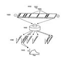
本発明の実施形態による反射モード装置の例は図1に提供されており、光源、検出器、光源と検出器の間のいくつかの部品を示す。光源105からの光はビーム分配器110を通過し、干渉計ミラー115によってスペクトルフィルター120へ反射される。スペクトルフィルター120からの光は、集束およびビーム操縦光学系125によってサンプルホルダー130の底部へ集束する。次いで、光は1回または複数回の通過で各サンプルと相互作用し、次いでサンプルホルダー130の外へ反射され、光学系135によって赤外カメラ140へ集束する。図1に示したこのシステムの実施形態は、(1)赤外線源、(2)放射を変調するデバイス、(3)サンプルホルダー、(4)赤外検出器、(5)スペクトルデータを収集し、処理し、示すコンピュータの5個の構成要素を含む。
Exemplary Device An example of a reflection mode device according to an embodiment of the present invention is provided in FIG. 1, showing a light source, a detector, and several components between the light source and the detector. The light from the
本発明の一実施形態による透過モードの装置を図2に示す。ここで、光源205からの放射は、ビーム分配器210を通過し、干渉計215によってスペクトルフィルター220へ反射される。スペクトルフィルター220からの光は集束光学系225によってサンプルホルダー230の底部へ集束し、ホルダー230内のサンプルアレイの各要素は同時に照射される。放射はサンプルを通過し、次いで光学系235によって集束して赤外カメラ240へ入射する。
A transmission mode device according to an embodiment of the invention is shown in FIG. Here, radiation from the
透過モードのサンプルホルダー
透過測定は、光源からの光をサンプルおよび検出器を通過させることによって行われ、一般に反射測定用に用いられるものとは異なるサンプルホルダーが必要である。溶液ベースの赤外透過測定は、一般に短い通路長の透過セルまたは流通セルを必要とする。両方の構成において、サンプルを通る光路長は水性溶液において長さ約5〜10ミクロンなどの短い距離に制限される。サンプルは、サンプルを拘束し、通路長を固定するように設計された、薄いガスケット(Teflon)によって分離された2個の赤外透過窓の間に挟むことができる。類似のサンプルホルダーが存在し、サンプルは、光の出入りが可能な赤外線に対して透明の側壁を有する管を通って流れる。どちらの構成も複数のサンプルから同時に赤外吸収スペクトルを得ることは不可能である。したがって、並列の複数の透過測定の問題は、(i)赤外ビーム中のすべてのサンプルの分離、(ii)必要な短い通路長の制御、(iii)溶媒蒸発の低減が必要なことであると言える。
Transmission Mode Sample Holder Transmission measurements are performed by passing light from the light source through the sample and detector, and generally require a different sample holder from that used for reflection measurements. Solution-based infrared transmission measurements generally require a transmission or flow cell with a short path length. In both configurations, the optical path length through the sample is limited to short distances such as about 5-10 microns in length in aqueous solutions. The sample can be sandwiched between two infrared transmission windows separated by a thin gasket (Teflon) designed to constrain the sample and fix the path length. There is a similar sample holder, and the sample flows through a tube with side walls that are transparent to infrared that allows light to enter and exit. In either configuration, it is impossible to obtain an infrared absorption spectrum from a plurality of samples at the same time. Thus, the problem of multiple transmission measurements in parallel is that (i) separation of all samples in the infrared beam, (ii) control of the required short path length, and (iii) reduction of solvent evaporation are required. It can be said.
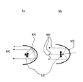
これらの問題は、図3に例示したように並列のサンプルホルダーの発見によって首尾よく対処された。このサンプルホルダーは、これらの問題を軽減するいくつかの特徴を有する。第1に、ホルダーは光がサンプルを通過することのできる赤外線透過性の領域を含む。これらの赤外線透過性のサンプリング領域はホルダー全体を赤外線透過性の媒体から構成することによって、または一連の赤外線透過性の窓を不透明な母材に一体化することによって作製することができる。第2に、サンプルホルダーは、図3に見られるように特定のサンプル注入口を含む。各サンプルの位置は、反応物、溶媒等の混合を可能にするいくつかのサンプル注入口を有することができる。最終的に、サンプル注入口はマイクロチャンネルによって赤外サンプリング領域に接続しており、口からサンプリング領域へ毛細管作用によってサンプルが動くことを可能にする。毛細管によって供給される短い通路長のサンプリング領域は、サンプルを通るビーム通路の制限および溶媒蒸発を低減するのに必要な絶縁に適するように修正することができる。 These problems were successfully addressed by the discovery of parallel sample holders as illustrated in FIG. This sample holder has several features that alleviate these problems. First, the holder includes an infrared transparent region that allows light to pass through the sample. These infrared transparent sampling regions can be made by constructing the entire holder from an infrared transparent medium or by integrating a series of infrared transparent windows into an opaque matrix. Second, the sample holder includes a specific sample inlet as seen in FIG. Each sample location can have several sample inlets that allow mixing of reactants, solvents, and the like. Finally, the sample inlet is connected to the infrared sampling region by a microchannel, allowing the sample to move from the mouth to the sampling region by capillary action. The short path length sampling area provided by the capillary can be modified to suit the insulation needed to limit the beam path through the sample and reduce solvent evaporation.
さらに具体的に、図3aは赤外線透過性の材料から作られた3個のサンプリングユニットを有するサンプルホルダー300を示す。最も左のユニットに見ることができるように、サンプル注入/取り出し口310はサンプルまたはサンプル流の添加または除去のために使用され、毛細管微小チャンネル320を通ってサンプリング領域330へ流れ、次いでサンプル注入/取り出し口340を出る。図3bに示したサンプルホルダー350は不透明な母材領域360をさらに含む。
More specifically, FIG. 3a shows a
これらのサンプルホルダーの赤外線透過性の領域は、ハロゲン化アルカリ塩(KBrまたはNaCl)、CaF2、BaF2、ZnSe、Ge、Si、薄いポリエチレン、またはAMTIRおよびKRS-5などの特殊な赤外材料など1種または複数の赤外線透過性の材料とすることができる。SiおよびGeなどの材料を使用することによって、サンプルアレイ全体をリソグラフィーおよび標準的な半導体加工技術を用いて微小加工することができる。不透明な母材はプラスチック、ガラス、ワックス、ポリマー、エラストマー等などの低コスト材料から作ることができる。 Infrared transparent regions of these sample holder, alkali halide salts (KBr or NaCl), CaF 2, BaF 2 , ZnSe, Ge, Si, thin polyethylene or AMTIR and special infrared materials such as KRS-5, One or more infrared transparent materials can be used. By using materials such as Si and Ge, the entire sample array can be microfabricated using lithography and standard semiconductor processing techniques. The opaque matrix can be made from a low cost material such as plastic, glass, wax, polymer, elastomer and the like.
内部反射モードのサンプルホルダーおよび構成要素
以下で詳細に述べるように、光を最適な効果へ導く新しいプリズム状構造を使用することによって、複数サンプルのより優れた減衰全内部反射を提供するさらに他の実施形態が発見された。これらのいくつかの発見に脈絡を付けるために、どのように減衰した全内部反射分光法が動作するかの概要を、どのようにこの手順に関連するいくつかの発見が使用されるかの説明と併せて提供する。この情報に基づいて、当業者であれば、特定のサンプル構成について提示された実施形態をさらに最適化することができよう。
Sample holder and components in internal reflection mode As described in detail below, yet another that provides better attenuated total internal reflection of multiple samples by using a new prismatic structure that guides light to optimal effects An embodiment has been discovered. An overview of how attenuated total internal reflection spectroscopy works to context some of these discoveries, and how some discoveries related to this procedure are used Provided together. Based on this information, those skilled in the art will be able to further optimize the presented embodiments for specific sample configurations.
本発明の多くの実施形態は、非常に強い赤外吸収体である水などのサンプルの減衰した全内部反射分光法を用いる。これらの実施形態において、光学セルに入るエネルギーのビームは、入射光がサンプル/サンプルホルダーの界面に衝突する角度が臨界角度よりも大きいとき、サンプルと光学セルの間の界面で全内部反射を起す。臨界角度は材料依存性があり、Snellの法則に基づく。角度はサンプルと光学セルの屈折率によって定まる。この角度は、本発明の実施形態によるプリズム状構造の寸法と配置に特に重要である。これは、光が臨界角度で、またはそれを超えて流体サンプル表面に衝突するとき、表皮(skimming)(消失する)波が発生するからである。この表皮波はサンプルと光学セルの間の界面に近接してサンプルと反応し、次いでセルを出る。 Many embodiments of the present invention use attenuated total internal reflection spectroscopy of a sample such as water, which is a very strong infrared absorber. In these embodiments, the beam of energy entering the optical cell causes total internal reflection at the interface between the sample and the optical cell when the angle at which the incident light impinges on the sample / sample holder interface is greater than the critical angle. . The critical angle is material dependent and is based on Snell's law. The angle is determined by the refractive index of the sample and the optical cell. This angle is particularly important for the dimensions and placement of prismatic structures according to embodiments of the present invention. This is because when the light impinges on the fluid sample surface at or beyond the critical angle, a skimming (disappearing) wave is generated. This skin wave reacts with the sample in proximity to the interface between the sample and the optical cell and then exits the cell.
発見された、以下に説明するプリズム状構造は、プローブ光を臨界角度と等しいか(さらに好ましくは)臨界角度よりも大きな角度で界面に入射させるために、サンプル/サンプル収容器の界面に入るようにプローブ光を制御する寸法と配置に設定される。一実施形態において、プリズム状構造は、プローブ光スペクトルビームがサンプル/収容器の界面にビームスペクトルの中間波長の光で測定された臨界角度の2度以内に入るように制御する。他の実施形態において、光ビームは臨界角度の0〜2、0〜5、0〜15、0〜30、0〜45、5〜10、5〜15、5〜30、15〜45度、または臨界角度よりも0〜45度大きな角度で入るように制御される。他の実施形態において、プリズム状透明構造は、反射損失を最小にするため、プローブ光スペクトルビームが固体媒体に対してより垂直な角度で固体媒体に入るように導く寸法と配置にされる。 The discovered prismatic structure, described below, enters the sample / sample container interface to allow the probe light to enter the interface at an angle equal to (or more preferably) greater than the critical angle. The dimensions and arrangement for controlling the probe light are set. In one embodiment, the prismatic structure controls the probe light spectrum beam to enter the sample / container interface within 2 degrees of the critical angle measured with light at intermediate wavelengths in the beam spectrum. In other embodiments, the light beam has a critical angle of 0-2, 0-5, 0-15, 0-30, 0-45, 5-10, 5-15, 5-30, 15-45 degrees, or It is controlled to enter at an angle 0 to 45 degrees larger than the critical angle. In other embodiments, the prismatic transparent structure is sized and arranged to direct the probe light spectrum beam to enter the solid medium at a more perpendicular angle to the solid medium to minimize reflection losses.
サンプルの中へのプローブ光スペクトルビームの浸透は短く、典型的に入射光の波長程度(式1)である。これは測定中にサンプルの通路長または容積を制御し測定する必要性をなくす。この特徴は、より便利で安価な複数サンプルアレイの使用を可能にし、より低い精度で探査ビームおよび検出器と光学的に連絡させることができる。吸収の大きな厚さ1mm以上のサンプルをこの構成で測定することができる。

それらの光学セルは個々の結晶に作製することができ、赤外測定には例えばシリコン、ゲルマニウム、セレン化亜鉛、AMTIR、KRS-5などの赤外線透過性の材料から作ることが好ましい。 These optical cells can be made into individual crystals, and are preferably made from infrared transmissive materials such as silicon, germanium, zinc selenide, AMTIR, KRS-5 for infrared measurements.
減衰した全内部反射の使用は、他者によって展開され、装置を作製するために有用な様々な構成要素が入手可能である。しかし、一般にそれらの装置は単一サンプルの使用に厳密に制限されてきた。多くの生物学的サンプルの高いスループット分析のためには、次に論じるように、プリズム状構造は本明細書で詳細にする他の特徴と組み合わせられる。 The use of attenuated total internal reflection has been developed by others, and various components are available that are useful for making devices. In general, however, these devices have been strictly limited to the use of a single sample. For high throughput analysis of many biological samples, the prismatic structure is combined with other features detailed herein, as discussed below.
高いサンプルスループットのためのプリズム設計
発明者達はいくつかのプリズム設計、デバイス、および多数のサンプルを並列に全内部反射アッセイする能力を大きく向上させるその使用方法を発見した。一般に、注意深く寸法を定めた光デバイスのプリズム特性を選択して、プローブ光(反射測定のためにサンプル界面に接触する光)はサンプルの界面に適切な角度で入るように制御される。本発明の実施形態は、プローブ光が同時に複数のサンプル・ウェル界面に異なる位置で入るデバイスを提供する。さらに、デバイスは、各サンプルの中へ入るほぼ同じ入射光角度(すなわち、10度以内、好ましくは5度以内、さらに好ましくは2度以内、好ましくは標準偏差の1度以内)を維持する。入射角度はアレイ全体にわたって臨界角度よりも大きいことが好ましい。
Prism Design for High Sample Throughput The inventors have discovered several prism designs, devices, and methods for their use that greatly improve the ability to assay multiple samples in total internal reflection in parallel. In general, the prism characteristics of a carefully sized optical device are selected and the probe light (light that contacts the sample interface for reflection measurements) is controlled to enter the sample interface at an appropriate angle. Embodiments of the present invention provide a device in which probe light enters multiple sample well interfaces at different locations simultaneously. Furthermore, the device maintains approximately the same incident light angle (ie, within 10 degrees, preferably within 5 degrees, more preferably within 2 degrees, preferably within 1 degree of the standard deviation) entering each sample. The incident angle is preferably greater than the critical angle throughout the array.
減衰した全内部反射測定用の3種類の有利なサンプルホルダーが発見された。第1の種類は、すべてのサンプルに対して大きな共通のプリズム状デバイスとして働く大きな光学デバイスの光接触によって、複数サンプルに実質上等しい光学処理を維持する。大きな光学デバイスは光を導いて各サンプルに同時に出入りさせる。好ましい実施形態において、大きな光デバイスの外部表面は、図4に見えるように、臨界角度と等しいかそれを超える入射角度で光をサンプル・ウェルの中へ導くような寸法にされる。 Three advantageous sample holders for attenuated total internal reflection measurements have been discovered. The first type maintains optical processing that is substantially equal to multiple samples by optical contact of a large optical device that acts as a large common prismatic device for all samples. Large optical devices direct light into and out of each sample simultaneously. In a preferred embodiment, the exterior surface of the large optical device is dimensioned to direct light into the sample well at an incident angle equal to or exceeding the critical angle, as seen in FIG.
図4は減衰した全反射サンプルホルダー410の作製されたアレイの使用を示す。アレイ410は、流体、特に水性液体、または固体サンプルを保持することの可能なサンプル・ウェルからなる。光学界面プリズム状デバイス430はアレイ410の底部に接触し、外部からの赤外線ビーム440を内部反射に適した条件下でサンプルとの界面に導くことが可能である。図4に示した構成において、赤外線ビーム440は透明なプリズム状デバイス430の表面に入射し、ホルダー410の中へ入射する。赤外線は、点線で描いたように、サンプル・ウェル420および他のサンプル・ウェルと相互作用し、次いでサンプルホルダー410から反射して出る。
FIG. 4 shows the use of a fabricated array of attenuated total
好ましい実施形態において、大きなプリズム状デバイス430は装置光学系に固定された部分であり、アレイ410は分離可能であり、サンプルの加工および機械から操縦して取り出すことが可能である。一実施形態において、アレイ410は赤外線透過性の材料を含み、再使用される。可視光を使用する他の実施形態において、アレイ410は安価なプラスチックなどの可視光に透明な材料を含み、廃棄可能である。好ましいサンプルアレイデバイスは、特に96個のウェルまたは96個のウェルの複数、384個、1536個、3072個のウェルなどの微小滴定プレートである。アレイの好ましいサイズは長さが約108ミリメートル、幅が約75ミリメートルである。一実施形態において、サンプルアレイは少なくとも96個のウェルを有する通常の微小滴定プレートに使用されるロボットによって処理される。
In a preferred embodiment, the large
発見された構造および本明細書で説明する特徴に従って、様々な形状と寸法を使用することができる。例えば、図5は、サンプルとサンプルに接触している510の透明材料の間の表面で光ビームが臨界角度を満足するかまたは超えるように、プローブ光ビーム(光ビーム530を参照)を曲げてアレイに入射させる、湾曲した表面を有する大きなプリズム状半球520と接触するサンプルアレイ510を示している。
Various shapes and dimensions can be used according to the discovered structure and the features described herein. For example, FIG. 5 shows bending of the probe light beam (see light beam 530) so that the light beam meets or exceeds the critical angle at the surface between the sample and the 510 transparent material in contact with the sample. A
図4および5で例示したように、これらの図で420と520で示した透明なプリズム材料は、おのおのサンプルホルダーに使用する材料と同じにすることができる。これらの図に示したプリズムまたは半球形状は、特に有利であるが、他の形状を用いることもできる。図4および5の実施形態において、透明なプリズム材料はサンプルホルダーの平坦な底部に接触し、典型的に平行な光ビームを導いて、再現性良く異なるサンプル表面へ入射させる。 As illustrated in FIGS. 4 and 5, the transparent prism material indicated by 420 and 520 in these figures can be the same as the material used for each sample holder. The prism or hemispherical shape shown in these figures is particularly advantageous, but other shapes can be used. In the embodiment of FIGS. 4 and 5, the transparent prism material contacts the flat bottom of the sample holder and directs a typically parallel light beam to reproducibly enter different sample surfaces.
反射/透過効率は光と光学媒体の間の入射角度に強く依存する。垂直な入射は最大の透過と最小の反射をもたらす。したがって、図4および5に示したものなどの光学構造を加えることによって、光は光学的に高密度の材料に垂直に近い入射で入ることが可能になり、反射損失が減少しサンプルへの光スループットが増加する。透過効率は、光学構造に広帯域の反射防止コーティングを加えることによってさらに向上させることができる。 The reflection / transmission efficiency depends strongly on the incident angle between the light and the optical medium. Normal incidence results in maximum transmission and minimum reflection. Thus, by adding optical structures such as those shown in FIGS. 4 and 5, light can enter optically dense materials at near normal incidence, reducing reflection loss and light to the sample. Throughput increases. Transmission efficiency can be further improved by adding a broadband antireflection coating to the optical structure.
プリズム状または半球状の光学系(図中構造430および520)は装置に残ることができ、サンプルホルダーを取り外して交換することが可能である。サンプルホルダーの平坦な底部とプリズム状または半球状の光学系の間の界面は完全ではない、すなわち、不均一さのために僅かな空気の空隙があり得ることを意味する。この空隙はさらに反射損失のある位置を表す。これを克服するには、指数整合性流体を使用して空隙が充填される。流体の屈折率は2種の材料の屈折率の間にある数値を有し、さらに好ましくは2種の固体相屈折率の間の中間(平均値の20%以内)であることが最も有利である。
Prismatic or hemispherical optics (
第2の種類の幾何形状構成は、複数の位置に光ビームを導いて、サンプルホルダーから反射して出る前に各サンプルと相互作用させる、各サンプル表面に隣接する分離したプリズム部を使用する。この第2の種類によるプリズム状サンプルアレイは図6に図示されている。アレイ610はウェル620および壁630を有する。壁630は不透明であることが有利である。最も左端のサンプルの下部の光学部640は、光ビーム650が入り、出る前に下部サンプル表面660で2度反射することが可能である。
The second type of geometric configuration uses separate prisms adjacent to each sample surface that direct the light beam to multiple locations and interact with each sample before reflecting off the sample holder. A prismatic sample array according to this second type is shown in FIG. Array 610 has
典型的に、サンプル・ウェルの下部表面はサンプルとの減衰した全内部反射を確立し、隣接する光学部(サンプルに接触する表面と連続しても、分離してもよい)はプリズム状である。この場合、下部表面は理想的には高いアスペクト比を有する、すなわち、長い長さと短い厚さを有するプリズムである。アスペクト比は1.5、2、3、4、5、7、8、または10さえ超えることが好ましい。プリズムは、上述の理由で、光が垂直に近い入射角度で入ることを可能にする。光は光ファイバーと同じように、プリズムの上部および下部表面の間に捕捉される。 Typically, the lower surface of the sample well establishes attenuated total internal reflection with the sample and the adjacent optics (which may be continuous or separate from the surface in contact with the sample) are prismatic . In this case, the lower surface is ideally a prism having a high aspect ratio, i.e. a long length and a short thickness. Preferably the aspect ratio exceeds 1.5, 2, 3, 4, 5, 7, 8, or even 10. The prism allows light to enter at near normal incidence for the reasons described above. Light is trapped between the upper and lower surfaces of the prism, similar to an optical fiber.
幾何形状構成の第3の種類において、多重内部反射要素が光学表面からサンプル・ウェルの中へ突出し、プリズム状光学表面が光学表面に形成される。多重内部反射要素の代表的なアレイが図7に示されている。図7の左側のサンプル・ウェル700に見られるように、光ビーム710は下部光学表面のプリズム状光学表面720へ入射し、多重内部反射要素730の中を伝播して登り、放射は、下部光学表面上のプリズム表面からビーム740として出る前にサンプルと複数の位置で相互作用する。
In a third type of geometric configuration, multiple internal reflective elements protrude from the optical surface into the sample well and a prismatic optical surface is formed on the optical surface. A representative array of multiple internal reflective elements is shown in FIG. As seen in the sample well 700 on the left side of FIG. 7, the
3種類の幾何形状構成の組合せを作ることができ、当業者には様々な寸法が認識されよう。 Three combinations of geometric configurations can be made, and various dimensions will be recognized by those skilled in the art.
内部反射を有する複数のサンプルの保持具幾何形状
このように今まで説明した多くの実施形態は、光学系に露出させた複数のサンプルとの複数の光相互作用を通常の光学系内で取り扱うために使用される光学系を用いる。個々の球内および個々の光伝導性ファイバー内の内部反射に基づく新しいサンプリング様式を展開するさらに他の設計が発見された。一実施形態において、各球および/または各ファイバーは個々のサンプルを表す。球の大きな集合は懸濁体中で同時に使用することができ、ファイバーの集合を大規模のサンプリングに使用することができる。
Multiple sample holder geometries with internal reflection Thus, many of the embodiments thus far described are for handling multiple optical interactions with multiple samples exposed in an optical system within a conventional optical system. The optical system used for the above is used. Still other designs have been discovered that develop new sampling modalities based on internal reflections within individual spheres and within individual photoconductive fibers. In one embodiment, each sphere and / or each fiber represents an individual sample. A large collection of spheres can be used simultaneously in suspension, and a collection of fibers can be used for large-scale sampling.
図13で近接アッセイを例示したように、内部反射は球の中で行うことができる。この図は、周囲の溶液よりも大きな屈折率を有する、赤外線透過性の媒体から作られた球を示す。この組合せは、従来の近接アッセイ(シンチレーション近接アッセイSPAなど)の特質を内部反射幾何形状のスペクトル識別に結びつける。図13は、意図された近接アッセイの概要図を示す。この実施形態において、赤外線透過性の高い屈折率の媒体から作られた球1310は、溶液中のタンパク質または他のアナライトと特別に結合することのできる、抗体などの生物学的な捕捉層(示していない)で被覆される。複数の球は溶液中で混合され、望ましい検体を捕捉される。アナライトの捕捉に続いて、球は、例えば赤外線透過性の光ファイバー1320の末端もしくはその中で固定化され、または赤外線1330を透過する管もしくは構造の中で固定化され、放射は光源からパイプを下がって球の中を伝播し、そこで反射して光パイプを上って戻り、検出される。球は前述のように内部反射サンプリングを可能にする。
As illustrated by the proximity assay in FIG. 13, internal reflection can be performed in a sphere. This figure shows a sphere made from an infrared transparent medium having a higher refractive index than the surrounding solution. This combination combines the attributes of conventional proximity assays (such as scintillation proximity assay SPA) with the spectral discrimination of the internal reflection geometry. FIG. 13 shows a schematic diagram of the intended proximity assay. In this embodiment, a
球捕捉アッセイは、懸濁体中の粒子の拡散を改善することによって、大きな固体表面上に固定化された結合相手よりも、多くの場合結合反応のためのより自然な環境およびより好ましい結合速度を提供する。さらに、ビーズは前述のように内部反射サンプリングを可能にする。さらに、捕捉技術と結びついて、小さなサイズは、類似のまたは異なる生物学的捕捉表面で被覆することのできる複数の球の使用を可能にする。この制御された多様性は特定のアナライトの識別および/または特定の球との相互作用を可能にする。 A sphere capture assay often improves the diffusion of particles in suspension, thereby often providing a more natural environment for binding reactions and a more favorable binding rate than binding partners immobilized on large solid surfaces. I will provide a. Furthermore, the beads allow for internal reflection sampling as described above. Further, coupled with capture technology, the small size allows the use of multiple spheres that can be coated with similar or different biological capture surfaces. This controlled diversity allows identification of specific analytes and / or interaction with specific spheres.
また、溶液から球を固定化するのに使用される捕捉技術によって球の間の区別をするために、球のサイズを制御することができる。固定化した球は、一実施形態の最も自然な条件で、その元の結合溶液中のアッセイを行うことができる。他の実施形態において、球は洗浄され、次いで捕捉される。さらに他の実施形態において、球はファイバーまたは管のアレイから作られたフィルター上に固定化される。管(図13に示した管1320)、ファイバー、または他の構造などの整合性光パイプに対する球のサイズ(図13の球1310)によって、特定の球の種類を対応する光パイプで捕捉することが可能になる。これは、それぞれ異なるコーティングを含む、異なるサイズの球で使用するのに特に有利である。これらのパイプの他の末端は、超スペクトル像で同時に像形成することのできる共通の収集点まで束ねることができる。一実施形態において、ファイバーが用いられ、内部反射測定用の特定サイズの球を収容するために各末端をカップに入れる。
Also, the size of the spheres can be controlled in order to distinguish between the spheres by the capture technique used to immobilize the spheres from solution. The immobilized sphere can be assayed in its original binding solution at the most natural conditions of one embodiment. In other embodiments, the spheres are washed and then captured. In yet other embodiments, the spheres are immobilized on a filter made from an array of fibers or tubes. Capturing a specific sphere type with the corresponding light pipe by the size of the sphere (
一実施形態において、光パイプの断面寸法は、光パイプが導波器のように働くことを可能にする。導波器の寸法は、光パイプを降下して伝播することのできる赤外波長の範囲を制御する。言い換えれば、導波器の遮断波長よりも長い波長を有する赤外線は、光パイプの中を伝播することができない。したがって、異なる光パイプを使用して、光パイプの寸法によって画定される、異なる赤外スペクトル領域をサンプリングすることができる。球のサイズは捕捉の目的のために光パイプと整合されるので、異なるサイズの球が異なるそれぞれの赤外スペクトル領域でのサンプリングに関与することができる。他の実施形態において、異なる光学的バンドパス特性の材料を含む光パイプが使用される。当業者であれば、どのようにして光パイプおよび/または管および/または他の構造の材料と寸法を変化させて、最適な波長の透過の特定の組合せを達成できるかを容易に認識することができよう。 In one embodiment, the cross-sectional dimension of the light pipe allows the light pipe to act like a director. The size of the director controls the range of infrared wavelengths that can travel down the light pipe. In other words, infrared light having a wavelength longer than the cutoff wavelength of the director cannot propagate through the light pipe. Thus, different light pipes can be used to sample different infrared spectral regions defined by the light pipe dimensions. Since the size of the sphere is aligned with the light pipe for acquisition purposes, different size spheres can be involved in sampling in different respective infrared spectral regions. In other embodiments, light pipes containing materials with different optical bandpass characteristics are used. One skilled in the art will readily recognize how light pipes and / or tubes and / or other structural materials and dimensions can be varied to achieve a specific combination of optimal wavelength transmissions. I can do it.
内部反射はファイバーで行うことができる。ファイバーは結合反応に関与する1個または複数の分子で被覆することができ、球について述べたものと同様に使用することができる。赤外線透過性のファイバーは多くの様々な技術によって被覆することができる。各ファイバーの寸法を制御して内部反射を高めることができる。さらに、ファイバーはファイバー束の末端での超スペクトル像を使用して複数のサンプルを同時に測定するために束ねることができる。同じサイズの考え、材料の考えおよびファイバーで得ることのできる導波器の性質はこの幾何形状に適用される。 Internal reflection can be done with fiber. The fiber can be coated with one or more molecules involved in the binding reaction and can be used in the same manner as described for the spheres. Infrared transparent fibers can be coated by many different techniques. The internal reflection can be increased by controlling the dimensions of each fiber. In addition, the fibers can be bundled to measure multiple samples simultaneously using the hyperspectral image at the end of the fiber bundle. The idea of the same size, the idea of materials and the properties of the directors that can be obtained with fibers apply to this geometry.
図14は、ファイバー1430が抗体1420で被覆された被覆ファイバーの実施形態を示す。光ビーム1410は多重内部反射を行い、超スペクトル像形成によって分析される。ファイバーは複数のアッセイデバイスの中へ束ねることができる。さらに、1個以上の複数ファイバーアッセイデバイスを逐次的にまたは同時に光学系および超スペクトル像形成で使用することができる。図15は、複数のファイバー光学サンプリングデバイス1520が複数のサンプル1510からスペクトル情報を同時に収集する代表的例を示す。赤外光学系1530は、超スペクトル検出装置1540によって同時に測定するために、光をファイバーの中および外へ通す。
FIG. 14 shows an embodiment of a coated fiber in which
さらに有利な特徴
放射源のスペクトル濾波
意図している用途の大部分は、5〜16.5ミクロン(1ミクロン=10-6メートル)、または2000〜600cm-1の範囲の波長のスペクトル情報を蓄積する必要がある。赤外源は可視から遠赤外の広い波長範囲にわたる放射を放出し、本発明の実施形態は様々な波長を使用する。望ましいスペクトル窓の外側の赤外波長はサンプルの加熱によって測定に悪い影響を与えることがある。すなわち、制御されない加熱は背景(基準線信号)の移動を招き、測定の雑音対信号比を低下させる。したがって、放射源からの赤外線を対象帯域幅に制限するために、スペクトルフィルターを含み、放射源から発生するが測定には必要のない他の放射を遮断することが好ましい。
Further advantageous features Spectral filtering of radiation sources Most of the intended applications need to store spectral information at wavelengths in the range of 5 to 16.5 microns (1 micron = 10 -6 meters), or 2000 to 600 cm -1 There is. Infrared sources emit radiation over a wide wavelength range from the visible to the far infrared, and embodiments of the present invention use a variety of wavelengths. Infrared wavelengths outside the desired spectral window can adversely affect the measurement by heating the sample. That is, uncontrolled heating causes movement of the background (reference line signal) and reduces the noise-to-signal ratio of the measurement. Therefore, in order to limit the infrared radiation from the radiation source to the target bandwidth, it is preferable to include a spectral filter to block other radiation generated from the radiation source but not required for the measurement.
それらの遮断は、小さな面積のサンプルのために光の強度を増加する(高密度出力の用途)とき特に価値がある。赤外フィルターは、赤外線透過性の基板上の特殊な材料(金属および半導体)薄膜の堆積によって作製することができる。薄膜層は、光学界面の透過と反射係数を変化させて、フィルターの通過を許される放射の帯域を制限する。一般的な概論は、http://www.ocli.com/pdf_files/products/gen_info_infrared_filters.pdfまたはO.S.Heavens Optical Properties of Thin Solid Films、1991、Dover Press、New Yorkの多くの光学情報源に見出すことができる。 These blockages are particularly valuable when increasing the light intensity for small area samples (high density output applications). Infrared filters can be made by depositing a special material (metal and semiconductor) thin film on an infrared transparent substrate. The thin film layer changes the transmission and reflection coefficients of the optical interface to limit the band of radiation that is allowed to pass through the filter. A general overview can be found at http://www.ocli.com/pdf_files/products/gen_info_infrared_filters.pdf or OSHeavens Optical Properties of Thin Solid Films, 1991, Dover Press, New York it can.
性能向上のための偏光フィルター
本発明の有利な実施形態は、偏光フィルターを用いて全内部反射スペクトルから追加の情報を得るために、偏光特性を開発する。一実施形態において、線形偏光フィルターが検出器前のビーム通路に置かれ、それによって、検出器に入る赤外線を或る好ましい偏光に制限する。典型的に、背景に対して配向された薄膜サンプルの信号を高めるために、偏光は反射面、または反射面に垂直に偏光された放射のいずれかが可能なように調整される。任意選択的に光弾性体変調器を使用して、左と右の円偏光状態の間の偏光を一般に10Hz〜10MHz、好ましくは100Hz〜1MHz、さらに好ましくは1KHz〜100KHzの周波数に急速に修正することができる。検出器は左対右の円偏光された赤外線の吸収差を測定する。この微分偏光はキラリティなどの立体化学情報の検出を提供する。一実施形態において、微分偏光は鏡像間の区別を可能にする。
Polarizing filter for performance enhancement An advantageous embodiment of the present invention develops polarizing properties to obtain additional information from the total internal reflection spectrum using a polarizing filter. In one embodiment, a linear polarizing filter is placed in the beam path in front of the detector, thereby limiting the infrared light entering the detector to some preferred polarization. Typically, the polarization is adjusted to allow either a reflective surface or radiation polarized perpendicular to the reflective surface to enhance the signal of a thin film sample oriented with respect to the background. Optionally using a photoelastic modulator to rapidly correct the polarization between the left and right circular polarization states, generally to a frequency of 10 Hz to 10 MHz, preferably 100 Hz to 1 MHz, more preferably 1 KHz to 100 KHz be able to. The detector measures the absorption difference of left-to-right circularly polarized infrared. This differential polarization provides detection of stereochemical information such as chirality. In one embodiment, differential polarization allows discrimination between mirror images.
変調
フーリエ変換と組み合わせた変調は、信号と分析の時間を向上させるのに特に強力である。光源からの光は干渉計で変調することが好ましい。好ましい干渉計はMichelson干渉計である。多数の他の干渉計設計が存在し、適している。1つまたは複数の実施形態において、原理的に、光路差を生成する任意の干渉計が役に立つであろう。
Modulation Modulation combined with Fourier transform is particularly powerful in improving signal and analysis time. The light from the light source is preferably modulated with an interferometer. A preferred interferometer is a Michelson interferometer. Many other interferometer designs exist and are suitable. In one or more embodiments, in principle, any interferometer that produces an optical path difference will be useful.
カメラ速度およびスペクトル解像度
多くの研究所ベースの中間赤外像形成分光計は、放射がサンプルと相互作用する前に、Michelson干渉計を使用して赤外線を変調する。しばしばMichelson干渉計は市販のFT-IR分光計にそのシステムの「光源」として使用される。Michelson干渉計は、2個の分割光源の構成要素間の光路差を発生させるために可動ミラーシステムを使用する。2ビーム干渉計のスペクトル解像度は干渉計中の全体的な光路差および検出器が読み取られる光路差の数(測定されるミラーの位置の数)に基づく。各光路差からのデータは数学的(例えばフーリエ)変換アルゴリズムおよびコンピュータを援用して吸収スペクトルに変換される。
Camera speed and spectral resolution Many laboratory-based mid-infrared imaging spectrometers use a Michelson interferometer to modulate the infrared radiation before the radiation interacts with the sample. Often the Michelson interferometer is used as a “light source” for the system in commercial FT-IR spectrometers. The Michelson interferometer uses a movable mirror system to generate an optical path difference between the components of two split light sources. The spectral resolution of a two-beam interferometer is based on the overall optical path difference in the interferometer and the number of optical path differences at which the detector is read (number of mirror positions measured). Data from each optical path difference is converted to an absorption spectrum with the aid of a mathematical (eg, Fourier) transformation algorithm and a computer.
2ビームシステムは非常に広い帯域幅(25,000〜13cm-1)、および非常に高い解像度(〜0.005cm-1)が可能であり、本発明の実施形態に有用であるので特別に説明する。1個または両方のミラーを動かす必要性は、測定される事象の動力学がミラーの速度と同じ時間の程度であるとき、時間に敏感な分析を複雑にする。言い換えれば、データはミラー通路の1つの長さを掃引するのに必要な時間で平均化され、速度と解像度は逆の相関がある。或る2ビーム干渉計はステップ-走査形態を用い、干渉計は段階的に固定光路差に進み、その通路長の周辺で少量の走査(小さなミラーの動き)を行う。 A two beam system will be specifically described as it is capable of very wide bandwidth (25,000 to 13 cm −1 ) and very high resolution (˜0.005 cm −1 ) and is useful in embodiments of the present invention. The need to move one or both mirrors complicates time sensitive analysis when the dynamics of the event being measured are on the same order of magnitude as the mirror speed. In other words, the data is averaged over the time required to sweep one length of the mirror path, and speed and resolution are inversely related. Some two-beam interferometers use a step-scan configuration, where the interferometer progresses stepwise to a fixed optical path difference and performs a small amount of scanning (small mirror movement) around its path length.
アレイからデータを得るのに必要な時間が増加するので、像形成システムへの影響は大きい。アレイ速度は一般にサイズと共に大きくなり、より小さなアレイはより速く、単一ピクセル検出器(FT-IR分光計に見られる)は一般にMHzの周波数で動作する。典型的な64×64ピクセルのHg-Cd-Teアレイは420Hzの最大フレーム速度を有し、特別のアレイは〜1KHzで動作が可能である。像は各光路差(ミラー位置)で取得しなければならず、スペクトル解像度は測定される異なるミラー位置の数に依存するので、より高い解像度は像形成の意味でより長い時間にも解釈される。 The impact on the imaging system is significant because the time required to obtain data from the array increases. Array speed generally increases with size, smaller arrays are faster, and single pixel detectors (as found in FT-IR spectrometers) generally operate at a frequency of MHz. A typical 64x64 pixel Hg-Cd-Te array has a maximum frame rate of 420 Hz, and a special array can operate at ~ 1 KHz. Images must be acquired at each optical path difference (mirror position), and the spectral resolution depends on the number of different mirror positions measured, so higher resolution is interpreted in longer time in the sense of imaging .
速度の問題をさらに複雑にするのは、多くの化学的および生物学的反応が多数のスペクトルを必要とし、データ処理の前に雑音低減のために平均化しなければならないことである。典型的なタンパク質実験は、例えば、平滑化、誘導、曲線当てはめ等などの1種または複数のアルゴリズムで数学的に処理するために、100個またはそれを超えるスペクトルの組合せを必要とするであろう。本発明の実施形態はアレイ中の各サンプルから迅速な複数のスペクトルを提供し、システムの性能を向上させ、良好なサンプルスループットを提供する。 To further complicate the speed problem, many chemical and biological reactions require a large number of spectra that must be averaged for noise reduction prior to data processing. A typical protein experiment will require a combination of 100 or more spectra for mathematical processing with one or more algorithms such as smoothing, derivation, curve fitting, etc. . Embodiments of the present invention provide rapid multiple spectra from each sample in the array, improving system performance and providing good sample throughput.
内部標準での修正
水性溶液中の赤外測定を行うとき、雑音に最も大きく寄与するものの1つは、背景(基準線)の移動である。この問題は背景(基準線)測定を行い、次いでその測定値を後続のスペクトルの参照に使用することによって対処される。多くの場合、貯蔵された基準線スペクトルは後続のスペクトルから差し引かれる。典型的に基準線は温度の変化、または湿度への変化、二酸化炭素含有量等などの大気条件の変化によって変化するであろう。これらの変化は不十分な減算、または背景効果の過剰補償として現れる。移動の問題は、希釈された分子濃度の測定で深刻であり、基準線の雑音が溶液中の分子からの望ましい信号を凌駕する。
Correction with internal standard When making infrared measurements in aqueous solutions, one of the most significant contributors to noise is the movement of the background (baseline). This problem is addressed by taking a background (baseline) measurement and then using that measurement for subsequent spectral reference. In many cases, the stored baseline spectrum is subtracted from subsequent spectra. Typically, the baseline will change with changes in temperature, or changes in atmospheric conditions such as changes to humidity, carbon dioxide content, and the like. These changes appear as insufficient subtraction or overcompensation of background effects. The problem of migration is severe in measuring diluted molecule concentrations, and baseline noise exceeds the desired signal from molecules in solution.
問題を緩和する1つの方法は、各実験前または背景が変化する度に、新しい基準線を取ることである。長い反応において、背景は頻繁に変化し得るので多くの新しい基準線測定が必要である。この増加した雑音の問題を訂正するには2つの方法が望ましい。 One way to alleviate the problem is to take a new baseline before each experiment or as the background changes. In long reactions, the background can change frequently and many new baseline measurements are required. Two methods are desirable to correct this increased noise problem.
修正の一方法は光に不安定な基を使用して化学反応を誘起し、誘起時間によって背景測定の時期を合わせることである。例えば、新しい基準線は各誘起事象前に測定することができる。各誘起事象後に得られるスペクトルを加えることは、基準線の変化のより少ないスペクトルを生成する。 One way to correct is to use a light labile group to induce a chemical reaction and time the background measurement by the induction time. For example, a new baseline can be measured before each induction event. Adding the spectrum obtained after each inductive event produces a spectrum with less baseline change.
他の方法は、1個または複数の参照サンプルをサンプルアレイ内の1個または複数のサンプル・ウェルの中に置き、ウェルから得られるスペクトルをアレイ中の他のサンプルの基準線として使用することである。例えば、96個のウェルプレート中の1個のウェルに他のすべてのウェルと類似しているが試験分子を含まない溶液を充填する。このウェルから収集したスペクトルを基準線(参照)スペクトルとして使用する。プレート中の他の95個のサンプルから収集したスペクトルを参照ウェルからの基準線スペクトルと参照する。この方法は、サンプルアレイ中の1個または複数のウェルを背景変化の参照として用いるために、並列データ取得の集合数を用いる。この補正手順は、分または時間などの長い反応時間にわたって複数のスペクトルを取得するのに特に価値がある。 Another method is to place one or more reference samples in one or more sample wells in the sample array and use the spectrum obtained from the wells as a reference line for the other samples in the array. is there. For example, one well in a 96 well plate is filled with a solution similar to all other wells but without the test molecule. The spectrum collected from this well is used as the baseline (reference) spectrum. The spectrum collected from the other 95 samples in the plate is referred to as the baseline spectrum from the reference well. This method uses a set number of parallel data acquisitions to use one or more wells in the sample array as a reference for background changes. This correction procedure is particularly valuable for acquiring multiple spectra over long reaction times such as minutes or hours.
増加した速度または感度のビニング(binning)
赤外焦平面アレイの速度の遅さは、この種の装置におけるデータ取得速度の主な制約要因である。スペクトル像形成の並列の性質はスペクトル平均化の速度を切り下げ、焦平面アレイの速度の遅さを補償する。一般に、赤外検出器の視野の中の各サンプルからの放射は、検出器上の1個以上のピクセルに衝撃を与える。所与のサンプルについてのすべてのそれらのピクセルからの強度データを組み合わせることによって、スペクトル平均化について上述したのと同じように、複数の単一検出器からの測定値を平均化することが可能になる。例えば、100個のスペクトルの平均化からの典型的なデータの組は、16ピクセルをビニングすることによって6走査で得ることができる。
Increased speed or sensitivity binning
The slow speed of the infrared focal plane array is a major limiting factor for the data acquisition speed in this type of device. The parallel nature of spectral imaging reduces the speed of spectral averaging and compensates for the slow speed of the focal plane array. In general, radiation from each sample in the infrared detector field of view impacts one or more pixels on the detector. By combining intensity data from all those pixels for a given sample, it is possible to average measurements from multiple single detectors as described above for spectral averaging Become. For example, a typical data set from an average of 100 spectra can be obtained in 6 scans by binning 16 pixels.
ビニングは、サンプルアレイのサイズが焦平面アレイのサイズよりも小さいサンプルのアレイで特に効果的である。64×64要素の焦平面アレイを用いる典型的な384サンプルアレイ(16×24サンプル)は、約5×2=10ピクセルを各サンプル点に置くであろう。10ピクセルのビニングは必要な走査を10分の一に低減する。従来のFT-IR分光計は、4cm-1の解像度(1.58cm/sのミラー速度)で100スペクトルを取得するのに76秒必要であろう。検出器を焦平面アレイに交換し、同じ10ピクセルをビニングすると、この取得時間は7.6秒に短縮するであろう。 Binning is particularly effective with arrays of samples where the size of the sample array is smaller than the size of the focal plane array. A typical 384 sample array (16 × 24 samples) using a 64 × 64 element focal plane array would place approximately 5 × 2 = 10 pixels at each sample point. Ten pixel binning reduces the required scan by a factor of ten. A conventional FT-IR spectrometer would require 76 seconds to acquire 100 spectra at 4 cm -1 resolution (1.58 cm / s mirror speed). Replacing the detector with a focal plane array and binning the same 10 pixels would reduce this acquisition time to 7.6 seconds.
一般に、真の像で動作する真の像形成システムはこのようなビニングを展開することができない。本明細書に述べる並列アレイシステムとは異なり、これらのシステムは空間解像度を高めるためにアレイ中の各ピクセルを必要とする。したがって、ここで述べるビニング方法はそれに関連する技術で必要なことに反する。すなわち、スペクトル平均化の取得速度の向上は並列データ取得に特定され、高い空間解像度を必要とされる場合には使用できない。好ましい実施形態は、データを収集するときにビニングを組み込み、ビニングしない機械より少なくとも10倍速い。サンプルアレイが焦平面アレイよりも多くの要素を有する場合、タイリング(tiling)を用いるならば、すなわち、複数の像を互いに繋ぎ合わせることによって、やはりビニングを用いることができる。 In general, a true imaging system operating with a true image cannot develop such binning. Unlike the parallel array systems described herein, these systems require each pixel in the array to increase spatial resolution. Therefore, the binning method described here goes against what is necessary in the related art. That is, an increase in acquisition speed of spectrum averaging is specified for parallel data acquisition and cannot be used when high spatial resolution is required. Preferred embodiments incorporate binning when collecting data and are at least 10 times faster than machines that do not bin. If the sample array has more elements than the focal plane array, binning can still be used if tiling is used, ie by joining multiple images together.
検出器
これらの目的のための並列赤外分光計は、5〜17ミクロンの波長範囲の中間赤外線に敏感な検出器を持たなければならない。これらの検出器は、Hg-Cd-Te、DTGS、サーモパイルなどの材料、量子ウェル赤外光検出器(QWIP)、ならびに多くの冷却および非冷却ボロメーターを含む。像形成または並列分光計において、これらの検出器は直線(1×128、1×256等)または矩形アレイ(64×64、128×128、4×256等)のいずれかで見られる。検出器および読み取り電子機器は赤外カメラの構成要素を形成する。カメラは、標準的なパーソナルコンピュータ上の数学的変換アルゴリズムを用いて入って来る放射をスペクトル像に変換する。
Detector Parallel infrared spectrometers for these purposes must have detectors that are sensitive to mid-infrared in the 5-17 micron wavelength range. These detectors include materials such as Hg-Cd-Te, DTGS, thermopile, quantum well infrared photodetectors (QWIP), and many cooled and uncooled bolometers. In imaging or parallel spectrometers, these detectors can be seen either as straight lines (1 × 128, 1 × 256, etc.) or rectangular arrays (64 × 64, 128 × 128, 4 × 256, etc.). The detector and reading electronics form the components of an infrared camera. The camera converts incoming radiation into a spectral image using a mathematical conversion algorithm on a standard personal computer.
サンプルホルダーおよび赤外用の溶媒
多数の化学的および生物学的反応が、水性または中間赤外線を良く吸収する有機溶媒中で起きる。例えば、中間赤外スペクトル領域の強い吸収は、一般に水性溶液の中で光路長を5〜10ミクロンに制限する。従来の一度に一回の分光計はこれらの環境でスペクトルを得るために典型的に3つの手法を用いる。それらは、短い通路長すなわち通過セル、全内部反射、および溶媒蒸発を含む。各手法は赤外線透過性のサンプルホルダー、または少なくとも透明なホルダーの領域の必要性によって制約を受ける。本明細書に述べる多くの実施形態はこの問題を(従来技術に比べて)サンプルサイズの縮小化、および多数のサンプルの同時アッセイによって対処する。
Sample Holders and Infrared Solvents Many chemical and biological reactions occur in aqueous or organic solvents that absorb mid-infrared well. For example, strong absorption in the mid-infrared spectral region generally limits the optical path length to 5-10 microns in aqueous solutions. Conventional once-at-a-time spectrometers typically use three techniques to obtain spectra in these environments. They include a short path length or pass cell, total internal reflection, and solvent evaporation. Each approach is constrained by the need for an infrared transparent sample holder, or at least a transparent holder area. Many embodiments described herein address this problem by reducing sample size (as compared to the prior art) and simultaneous assaying of multiple samples.
赤外光源および集束
本発明の実施形態は、光と対象分子に見出される化学結合電子との相互作用によって得られる診断信号を提供する。診断信号は検出された光信号に相当する電子衝撃から生成する。したがって、良好な雑音(不規則な電子的背景信号)対信号比は、測定時間が短くなると処理された光の量(および光から得られる電気信号)がより小さくなるので、迅速な測定値を得るために重要である。赤外光は、望ましいスペクトル処理が一般に4000〜400cm-1(2.5〜25ミクロン)1で画定される光スペクトルの中間赤外領域で分子の基本振動共鳴を伴う、多くの実施形態に用いられる。生物学的化合物の大部分は1800〜600cm-1(5.5〜16.7ミクロン)に制限される。
Infrared Light Sources and Focusing Embodiments of the present invention provide diagnostic signals obtained by the interaction of light and chemically bonded electrons found in the molecule of interest. The diagnostic signal is generated from an electron impact corresponding to the detected optical signal. Therefore, a good noise (irregular electronic background signal) to signal ratio is a quick measurement because the amount of light processed (and the electrical signal derived from the light) becomes smaller as the measurement time is shortened. Is important to get. Infrared light is used in many embodiments with fundamental vibrational resonances of the molecules in the mid-infrared region of the light spectrum where the desired spectral processing is generally defined by 4000-400 cm −1 (2.5-25 microns) 1 . The majority of biological compounds are limited to 1800-600 cm -1 (5.5-16.7 microns).
赤外領域のプローブ光を発生するためには、「グローバー(glowbar)」(SiCなどの熱い材料)などの黒体放射源、サンプルまたは場の固有の熱放射、または太陽赤外線から典型的に使用される。好ましい光源は、単一グローバー(シリコンカーバイド棒)、Nernst発光体(希土類酸化物の円筒)、または白熱線を含む。光源は、典型的に出力〜50〜100W、およびビーム直径〜4cm、またはビーム出力密度〜4W/cm2を有することができる。この出力密度は光学系を小さなサンプルに焦点を合わせることによって高めることができ、アパーチャーを光源とサンプルの間に置くときに低下させることができる。この出力密度は、ビーム通路中の単一サンプル、またはビームが特定の点に集束することのできる小さな面積のサンプルを含む従来の赤外実験には許容される。数百個の小さなサンプルが同時に測定されるときに存在する大面積のサンプリング環境において、有効面積を拡大するためにビームを広げることは、サンプルの各位置での出力密度を低下させる。したがって、より大きなサンプルの拡大した面積に有利な出力密度を維持するために、赤外光源の出力を増加することが望ましい。 Typically used from black body radiation sources such as “glowbars” (hot materials such as SiC), sample or field intrinsic thermal radiation, or solar infrared to generate infrared probe light Is done. Preferred light sources include single glow bars (silicon carbide rods), Nernst emitters (rare earth oxide cylinders), or incandescent rays. The light source can have typically output ~50~100W, and beam diameter ~4cm or a beam power density ~4W / cm 2,. This power density can be increased by focusing the optical system on a small sample and can be reduced when the aperture is placed between the light source and the sample. This power density is acceptable for conventional infrared experiments involving a single sample in the beam path, or a small area sample where the beam can be focused to a specific point. In a large sampling environment that exists when hundreds of small samples are measured simultaneously, expanding the beam to expand the effective area reduces the power density at each location of the sample. Therefore, it is desirable to increase the output of the infrared light source in order to maintain an advantageous power density for the enlarged area of the larger sample.
一実施形態において、スペクトルは生物学および化学工業で通常使用される「標準的な」微小滴定プレート形態から同時に集められる。これらのプレートは96個、384個、768個、1536個、3072個、4608個、6144個または他の数のサンプル・ウェルのアレイを保持することができる。滴定プレート形態のサンプルホルダーの関連する面積は、約80cm2であり、各サンプル位置で同じ4W/cm2を生成するのに〜350Wの光源強度が必要である。この出力は任意のアパーチャーを収容するため、またはビーム通路の光学損失のために、任意選択的に増加することができる。光源強度を増加させるために、より大きなグローバーまたはNernst光源を有利に使用することができ、それによって、光源のより大きな表面積がより多くの放射をもたらす。替わりに、縦に並べた複数のより低強度の光源を使用することができる。後者の実施形態において、パラボラ状ミラーを用いていくつかの光源からの光を集め、サンプルの方向に視準することができる。後者のいくつかの実施形態を図8に示す。図8aおよび8bに示したより低強度の3個の光源810は、それぞれ集団でまたは並列に配置することができ、これらの図で光線830で示したように、パラボラ反射器820は放射された光を平行に導くことが可能である。
In one embodiment, the spectra are collected simultaneously from “standard” microtiter plate formats commonly used in the biological and chemical industries. These plates can hold an array of 96, 384, 768, 1536, 3072, 4608, 6144 or other numbers of sample wells. Related area of the sample holder of the titration plate form is about 80 cm 2, it is necessary to light source intensity of ~350W for each sample position to produce the same 4W / cm 2. This output can optionally be increased to accommodate any aperture or due to optical losses in the beam path. To increase the light source intensity, a larger Glover or Nernst light source can be advantageously used, whereby the larger surface area of the light source results in more radiation. Alternatively, a plurality of lower intensity light sources arranged vertically can be used. In the latter embodiment, parabolic mirrors can be used to collect light from several light sources and collimate in the direction of the sample. Several embodiments of the latter are shown in FIG. The three lower-
装置の性能を高めるための生物化学的および細胞的集束
本明細書に述べる減衰した全内部反射法は、プローブ光からサンプルへの表皮(消失する場)波の近似に依存する。サンプルの容積を、探査部分(表面波で可能)と探査されない部分(波へ測定可能に影響を及ぼすには本質的にあまりにも遠い)に機能的に分離する、生物化学的集束および細胞的集束技術が発見された。両方の集束技術において、目標を表皮波の存在するサンプル容積の一部に物理的に濃縮することによって、測定を向上させるためのより高い雑音対信号が得られる。
Biochemical and cellular focusing to enhance device performance The attenuated total internal reflection method described herein relies on an approximation of the epidermis (disappearing field) wave from the probe light to the sample. Biochemical and cellular focusing that functionally separates the volume of the sample into exploration parts (possible with surface waves) and non-exploration parts (essentially too far to have measurable effects on the waves) Technology was discovered. In both focusing techniques, by physically concentrating the target to a portion of the sample volume where the skin wave is present, a higher noise versus signal is obtained to improve the measurement.
生物化学的集束において、分子は溶液から引き出され、より小さな容積に濃縮され、表面波へ露出される。濃縮ステップは、例えば、生物化学的相互作用層によって、または例えば以下に述べる等電点電気泳動などの活性工程によって行うことができる。前者の代表的実施形態を図9に示す。図9は、光学表面910を示し、その上に表面結合配位子920が固定化される。表面結合配位子920は次にスペーサー配位子930に付着し、次いで捕捉配位子940に付着する。典型的に液体媒体全体に存在するアナライト950は、捕捉配位子940に結合する。アナライト950の捕捉層への結合は、より多くのアナライトを表面波の届く範囲内に集め、したがって信号へのアナライトの影響を高める。
In biochemical focusing, molecules are withdrawn from solution, concentrated to a smaller volume, and exposed to surface waves. The concentration step can be performed, for example, by a biochemical interaction layer or by an active process such as, for example, isoelectric focusing described below. The former exemplary embodiment is shown in FIG. FIG. 9 shows an
図9に示したサンプルアレイの各要素は、望ましい生物化学的相互作用に微調整された類似のまたは異なる相互作用層を有する。それらの表面結合層は多くの生物センサー設計に使用され、診断用途に非常に一般的である。結合層は典型的に層を表面に結合する配位子、様々なスペーサーすなわち結合層、および抗体などの捕捉配位子またはタンパク質を含む。表面の種類に応じて、表面結合用の異なる配位子を選択することができる。シリコンに結合する配位子は、例えばポリエチレンに結合する配位子とは一般に異なる。例えば、Sluka等に発行された米国特許第5,851,840号、Hammenに発行された米国特許第5,240,602号は、配位子全体について、また、分子をシリコン表面に結合する方法を記載している。捕捉配位子の使用はよく知られており、例えば、Blackburn等に発行された米国特許第6,264,825号、Ebersole等に発行された第5,658,732号、Jaeger等に発行された第5,498,551号その他多数に記載されている。 Each element of the sample array shown in FIG. 9 has similar or different interaction layers that are fine-tuned to the desired biochemical interaction. These surface binding layers are used in many biosensor designs and are very common in diagnostic applications. The binding layer typically includes a ligand that binds the layer to the surface, various spacers or binding layers, and a capture ligand or protein such as an antibody. Depending on the type of surface, different ligands for surface binding can be selected. The ligand that binds to silicon is generally different from, for example, a ligand that binds to polyethylene. For example, US Pat. No. 5,851,840 issued to Sluka et al. And US Pat. No. 5,240,602 issued to Hammen describe the entire ligand and method for attaching molecules to a silicon surface. The use of capture ligands is well known and is described, for example, in US Pat. No. 6,264,825 issued to Blackburn et al., 5,658,732 issued to Ebersole et al., 5,498,551 issued to Jaeger et al. And many others. Has been.
細胞的集束において、細胞の表面または内部で優先的に起きる分子相互作用は、細胞のサイズに整合するまたはそれを超えるように選択した、サンプルの表面波領域内に位置するプローブ光波長を用いて探査される。この実施形態において、細胞は表皮波が作られるサンプル表面に接着する。表皮波を発生するプローブ光の平均波長は、少なくとも5ミクロンであることが好ましく、さらに好ましくは少なくとも7.5ミクロンであり、或る実施形態において10ミクロンを超え、15ミクロンさえも超える。細胞の厚さ(サンプル表面上に平坦に横たえたとき)はプローブ光の平均波長の2倍を超えないことが好ましく、プローブ光の平均波長を超えないことがさらに好ましい。表面波は固体の透明媒体から遠く展延するのに十分長く、培養媒体の大部分を覆うには十分長くないので、細胞内および細部表面の分子構造の優先的検出が可能である。 In cellular focusing, molecular interactions that occur preferentially on or inside the cell are selected using probe light wavelengths located within the surface wave region of the sample, selected to match or exceed the size of the cell. Explored. In this embodiment, the cells adhere to the sample surface where the epidermal wave is created. The average wavelength of the probe light that generates the skin wave is preferably at least 5 microns, more preferably at least 7.5 microns, and in some embodiments greater than 10 microns and even greater than 15 microns. The cell thickness (when lying flat on the sample surface) preferably does not exceed twice the average wavelength of the probe light, and more preferably does not exceed the average wavelength of the probe light. Since surface waves are long enough to spread far from a solid transparent medium and not long enough to cover most of the culture medium, preferential detection of intracellular and detailed surface molecular structures is possible.
他の実施形態において、サンプル表面近くに発生する分子の事象と遠くに起きるものとの間を区別するために2種類のプローブ光が使用される。1つの光は他よりも長い波長を有し、より浸透的な表面波を発生する。例えば、分子と表面に付着している細胞膜表面のデータを得るのに、波長600ナノメートルの探査可視光を使用することができる。同時にまたは異なる時間に、分子と典型的に光学表面から10倍遠い細胞膜表面の情報を得るために、6000ナノメートルのプローブ光を使用することができる。 In other embodiments, two types of probe light are used to distinguish between molecular events occurring near the sample surface and those occurring far away. One light has a longer wavelength than the other and generates a more permeable surface wave. For example, exploratory visible light at a wavelength of 600 nanometers can be used to obtain data on molecules and cell membrane surfaces attached to the surface. At the same time or at different times, 6000 nanometer probe light can be used to obtain information about the molecules and the cell membrane surface, typically 10 times farther from the optical surface.
等電点電気泳動からの分子情報
本発明の実施形態に有用な非常に望ましい生物化学的集束技術は、電気泳動、および特に等電点電気泳動である。本明細書に述べる材料と方法は、等電点電気泳動からの、ならびに他の生物化学的分離技術からの等電点によって分離された分子の、分子的な詳細を監視するのに使用することができる。実施形態は、特別に分離された分子およびそれらの結合相手との相互作用の識別を可能にする情報を提供する。これらの実施形態は、分子の次元の違う複雑さを実時間で明らかにすることによって、従来の電気泳動分離技術よりも大きな利点を提供する。例えば、その天然の環境における複雑なタンパク質混合物を電気泳動によって、さらに好ましくは等電点電気泳動によって分離し、他の物質で標識を加えることなく分析することができる。
Molecular Information from Isoelectric Focusing A highly desirable biochemical focusing technique useful for embodiments of the present invention is electrophoresis, and in particular isoelectric focusing. The materials and methods described herein should be used to monitor the molecular details of molecules separated by isoelectric points from isoelectric focusing as well as from other biochemical separation techniques. Can do. Embodiments provide information that allows identification of specially isolated molecules and their interactions with their binding partners. These embodiments offer significant advantages over conventional electrophoretic separation techniques by revealing the different complexity of molecular dimensions in real time. For example, complex protein mixtures in their natural environment can be separated by electrophoresis, more preferably by isoelectric focusing, and analyzed without labeling with other substances.
等電点電気泳動の実時間の超スペクトル分析装置は、電源と、流体サンプルホルダーの内容物に接触する少なくとも2個の電極と、広帯域赤外線の光源と、広帯域赤外線の変調器と、流体サンプル保持チャンバーから出る赤外線を検出するための赤外線検出器と、赤外線検出器からのデータを分析するコンピュータとを含むことが有利である。等電点電気泳動の好ましい実施形態において、使用中に、1種または複数の両性電解質を含む水性溶液は電極によって確立された電圧勾配に露出され、pH勾配を形成する。例えば、サンプルは保持チャンバーに入る溶液中に混合することができ、あるいは、別の時間に1個または複数の孔を経由して加えることができる。分子間相互作用の分光法的研究に望ましいであろうように、2種またはそれ以上のサンプルを同時にまたは異なる時間に保持チャンバーに加えることができる。 Isoelectric focusing real-time ultraspectral analyzer consists of a power source, at least two electrodes in contact with the contents of the fluid sample holder, a broadband infrared light source, a broadband infrared modulator, and a fluid sample holder It is advantageous to include an infrared detector for detecting the infrared light exiting the chamber and a computer for analyzing the data from the infrared detector. In a preferred embodiment of isoelectric focusing, during use, an aqueous solution containing one or more ampholytes is exposed to a voltage gradient established by an electrode to form a pH gradient. For example, the sample can be mixed into the solution entering the holding chamber, or can be added via one or more holes at another time. Two or more samples can be added to the holding chamber simultaneously or at different times, as would be desirable for spectroscopic studies of intermolecular interactions.
例えば、サンプルホルダーは、当技術分野に知られている直線状の一次元毛細管、または二次元毛細管、または容器とすることができる。感度を高めるのに有用な他の実施形態において、ホルダーは、分光探査に露出された小さな容積と、探査される容積から離れた大きな容積を有する部分を好ましくはその中間に有する。望ましい実施形態において、ホルダーは、小さな探査される容積と両側の大きな容積を備える水時計に似ており、探査の前に等電点電気泳動によって分子を濃縮させる。サンプル容積は、全サンプル容積に対して0.1、0.03、0.01、0.003、0.001、0.0003、0.0001、0.00005またはより小さいことが有利であり、等電点電気泳動は望ましい分子種の全量の少なくとも10%、25%、50%、60%、または90%以上をサンプリング容積に濃縮することが好ましい。したがって、分析手順自体の間に、少なくとも5、10、25、50、100、250、1000、2000倍またはそれを超えて濃縮することのできる分子からスペクトルを得ることができる。他の実施形態において、サンプルホルダーは、ネジ、膜、スクリーン、またはその内部に固定化される他の形の物質などの部分を含み、或る種類の分子種を固定化し、三次元での分光法分析を容易にする。 For example, the sample holder can be a linear one-dimensional capillary, or two-dimensional capillary, or container known in the art. In other embodiments useful for increasing sensitivity, the holder preferably has a portion with a small volume exposed to the spectroscopic probe and a large volume away from the probed volume, preferably in the middle. In a preferred embodiment, the holder resembles a water clock with a small probed volume and large volumes on both sides, and concentrates the molecules by isoelectric focusing prior to the probe. The sample volume is advantageously 0.1, 0.03, 0.01, 0.003, 0.001, 0.0003, 0.0001, 0.00005 or smaller relative to the total sample volume, and isoelectric focusing is at least 10% of the total amount of the desired molecular species, Preferably 25%, 50%, 60%, or 90% or more is concentrated in the sampling volume. Thus, spectra can be obtained from molecules that can be enriched at least 5, 10, 25, 50, 100, 250, 1000, 2000 times or more during the analytical procedure itself. In other embodiments, the sample holder includes parts such as screws, membranes, screens, or other forms of material immobilized therein, to immobilize certain types of molecular species and to perform spectroscopic analysis in three dimensions. Facilitate legal analysis.
装置は焦平面アレイ検出器を利用して平面に配置された材料、および複数のサンプルを同時に検出することができる。複数のサンプルは、例えば本明細書に述べる赤外線透過性の通常のホルダー内に配置することができる。ゲルなどの支持体の必要性を省くことによって、本発明のこの実施形態は分光法分析の前および後の両方で流体の自動取り扱いが可能になる。例えば、微小滴定プレートをサンプリングし、本明細書で述べる光学的特徴を有する微小滴定プレート自体を直接使用することができる。等電点電気泳動濃縮および分析の後、分析された材料は選択的に(すなわちより精製された形で)または非選択的に(サンプル全体)質量分光法分析などのさらなる分析へ取り出すことができる。(a)分子濃縮、(b)分子相互作用、(c)等電点電気泳動分離を同時に構成し、ならびに高いスループットの複数サンプル分析ができるので、それらの実施形態によって多くのデータを取得できることは容易に認識されよう。 The apparatus can simultaneously detect materials placed in a plane and multiple samples using a focal plane array detector. The plurality of samples can be placed, for example, in a conventional infrared transparent holder as described herein. By eliminating the need for a support such as a gel, this embodiment of the invention allows automatic handling of fluid both before and after spectroscopic analysis. For example, a microtiter plate can be sampled and the microtiter plate itself having the optical features described herein can be used directly. After isoelectric focusing and analysis, the analyzed material can be selectively (ie, in a more purified form) or non-selectively (whole sample) for further analysis such as mass spectrometry analysis. . Since (a) molecular enrichment, (b) molecular interaction, and (c) isoelectric focusing separation can be configured simultaneously, and multiple samples can be analyzed with high throughput, it is possible to acquire a lot of data according to these embodiments. It will be easily recognized.
望ましい実施形態において、混合物中のタンパク質をその等電点によって分離するのに高解像度の等電点電気泳動が用いられる。導光光学系での超スペクトル赤外像形成は、集束させたタンパク質の同時的な全列監視を可能にする。一般に、溶液中のタンパク質は、赤外線透過性の材料から作られた狭い毛細管の中へ導入され、電場が印加される。電場に誘起されたタンパク質がタンパク質の自然の等電点で鋭い帯の中へ動くことは、超スペクトルカメラで監視される。光は透過モードまたは内部反射サンプリングモードを用いて処理され使用することができる。 In a preferred embodiment, high resolution isoelectric focusing is used to separate proteins in a mixture by their isoelectric points. Superspectral infrared imaging with light guiding optics allows simultaneous full-line monitoring of focused proteins. In general, proteins in solution are introduced into narrow capillaries made of infrared transparent material and an electric field is applied. The movement of the protein induced by the electric field into a sharp band at the natural isoelectric point of the protein is monitored with a hyperspectral camera. Light can be processed and used using transmission mode or internal reflection sampling mode.
本発明のこの実施形態のいかなる理論にも拘束されることは望まないが、印加された電場の影響下における分子の超スペクトル像形成は、ゲル(またはその他)支持体および着色の必要性と欠点を克服する。すなわち、等電点電気泳動に用いられるゲルなどの支持体は、電場が消されたときに拡散を防ぐために必要であり、タンパク質の帯を視認化するための着色が可能になる。タンパク質の帯は、典型的に着色の前に停止される電場の存在なしに着色され分析される。電場がないと、タンパク質の帯はタンパク質が拡散するに伴って不鮮明になる。ゲルの存在はタンパク質の拡散を制限する。タンパク質を着色する必要性を省くことによって、ゲルはもはや必要ではない。望ましい実施形態において、より鋭い帯、ゲルからの自由度、および他の標識、および実時間の検出が可能である。 While not wishing to be bound by any theory of this embodiment of the present invention, the hyperspectral imaging of molecules under the influence of an applied electric field is a necessity and disadvantage of gel (or other) supports and coloration. Overcome. That is, a support such as a gel used for isoelectric focusing is necessary to prevent diffusion when the electric field is extinguished, and coloring for visualizing a protein band becomes possible. Protein bands are colored and analyzed without the presence of an electric field that is typically stopped prior to coloring. In the absence of an electric field, the protein band becomes unclear as the protein diffuses. The presence of the gel limits protein diffusion. By eliminating the need to color the protein, the gel is no longer necessary. In desirable embodiments, sharper bands, degrees of freedom from the gel, and other labels, and real-time detection are possible.
実施形態のさらに他の利点は、赤外振動スペクトルが、タンパク質と他の分子との相互作用などのタンパク質についての豊富な情報を提供することである。例えば、結合した、または結合していないタンパク質は異なる等電点を有し、したがって泳動中に明瞭な帯を示す。標識のない全列検出は実時間で結合事象の監視を可能にし、これは結合動力学についての正確な情報を提供することができる。多くの場合結合は一時的であり、電場を連続的に印加することによって、結合したタンパク質が非結合タンパク質へ戻る量の変化を監視することが可能である。したがって、結合と分離の動力学をインシトゥーに測定することができる。さらに、新しい製品を製造するために、1種または複数の基質と酵素との結合を実時間で監視することができる。充填しない1種または複数の基質を列の媒体に存在させることができ、他の化学反応によって導入することができ、または物理的に列空間に加えることができる。列空間中の1つの位置に集束させた酵素または他の触媒は、見ることのできるまたは間接的に分光法的に推論(タンパク質の配座移動によるものなど)することのできる、短命または長命の製品を生成することができる。一実施形態において、基質自体は、可視光および/または紫外光であり、配座の移動を起し、または分子または列空間内に集束した大きな分子錯体中の物質を放出する。 Yet another advantage of embodiments is that the infrared vibrational spectrum provides a wealth of information about the protein, such as the interaction of the protein with other molecules. For example, bound or unbound proteins have different isoelectric points and thus show a clear band during migration. Label-free full-row detection allows monitoring of binding events in real time, which can provide accurate information about binding kinetics. In many cases, binding is temporary, and it is possible to monitor changes in the amount of bound protein returning to unbound protein by applying an electric field continuously. Thus, the binding and separation kinetics can be measured in situ. In addition, the binding of one or more substrates to the enzyme can be monitored in real time to produce a new product. One or more unfilled substrates can be present in the row medium, introduced by other chemical reactions, or physically added to the row space. Enzymes or other catalysts focused on a single location in the row space are short-lived or long-lived that can be seen or indirectly spectroscopically inferred (such as by protein conformational transfer) A product can be generated. In one embodiment, the substrate itself is visible light and / or ultraviolet light, causing conformational movement or releasing the substance in a large molecular complex focused in a molecule or column space.
本明細書で述べるように、実施形態は、より高い解像度の研究のために、機能的なパラメーターに結びついた物理的分離パラメーターによって、分子および分子錯体の識別を可能にする。新しい分子のパラメーターの検出は、特に赤外領域の超スペクトル像形成を実時間天然タンパク質の相互作用と組み合わせることによって可能である。例として、変化したアミノ酸を有するが一般に電荷の影響を受けない、突然変異したタンパク質は、サイズまたは電荷に依存する分離技術によっては解決されないであろう。しかし、タンパク質中の配座の変化に影響を与える任意のそれらの突然変異はこの技術によって解決することができる。この新しい構造的に静止した突然変異は、新しく成長しているプロテオミクス(proteomics)の分野に非常に重要であり、本発明の実施形態は多数のタンパク質変化が作られるプロテオミクスの大規模な分析を意図している。超スペクトル像形成で配座変化を直接アッセイすることによって、複数のサンプルの迅速な実時間分析が可能になる。 As described herein, embodiments allow for the discrimination of molecules and molecular complexes by physical separation parameters coupled to functional parameters for higher resolution studies. Detection of new molecular parameters is possible in particular by combining hyperspectral imaging in the infrared region with real-time natural protein interactions. As an example, a mutated protein that has an altered amino acid but is generally unaffected by charge will not be resolved by separation techniques that depend on size or charge. However, any of those mutations that affect conformational changes in the protein can be resolved by this technique. This new structurally stationary mutation is very important in the field of newly growing proteomics, and embodiments of the present invention are intended for large-scale analysis of proteomics where numerous protein changes are made. is doing. Direct assay for conformational changes with hyperspectral imaging allows rapid real-time analysis of multiple samples.
その天然環境におけるタンパク質の配座移動および他の現象を検出できることによって、高解像度の分離と、他の診断試験では容易に見出せなかった迅速な反応アッセイとを結びつけることが可能になる。さらに、超スペクトル像形成を用いて、複数のタンパク質を同じ帯または点内に存在するものさえ、先進のスペクトル加工手段を使用して解きほぐすことができる。このようにして、スペクトルフィンガープリントは「2D」分離の第二の次元データを形成する。特別の利点は、振動スペクトルを捕捉する間、タンパク質をその等電点に保持することができ、したがって、その天然環境におけるタンパク質のスペクトルが確保されることである。したがって、実施形態は、豊富なスペクトル情報へ検出が広がることによって、屈折率、紫外線吸収、蛍光、および化学蛍光などの帯域を検出する単純な検出方法に属する従来技術よりも改善される。一実施形態において、等電点電気泳動などの一次元的な手順は、類似の等電点でのデータなど、データの第二次元(赤外スペクトルフィンガープリント)を提供することによって、重なり合うタンパク質を分離する二次元のゲル電気泳動と同じになる。 The ability to detect protein conformation and other phenomena in its natural environment makes it possible to combine high resolution separations with rapid reaction assays that were not easily found in other diagnostic tests. Furthermore, using hyperspectral imaging, multiple proteins can be unraveled using advanced spectral processing tools, even those that are in the same band or point. In this way, the spectral fingerprint forms the second dimension data of “2D” separation. A particular advantage is that the protein can be held at its isoelectric point while capturing the vibrational spectrum, thus ensuring the spectrum of the protein in its natural environment. Thus, the embodiments are improved over the prior art belonging to simple detection methods that detect bands such as refractive index, ultraviolet absorption, fluorescence, and chemical fluorescence by spreading detection to abundant spectral information. In one embodiment, a one-dimensional procedure, such as isoelectric focusing, provides overlapping proteins by providing a second dimension of data (infrared spectral fingerprint), such as data at similar isoelectric points. It becomes the same as the two-dimensional gel electrophoresis to be separated.
図16は超スペクトル像形成が、等電点分離チャンバー1620に導入されたサンプル1610からの溶質の位置、動き、結合分子の詳細を明らかにする実施形態を示している。帯1625はチャンバー1620中に等電点電気泳動によって形成される。赤外光学系および検出器1630は同時に帯1625の像を形成し信号パターン1640を発生する。信号パターンは、グラフ1650に描いたように、そのときに起きるスペクトル変化を測定するのに使用される。超スペクトル測定を実時間で実施する能力は、高密度の粘性の高いまたはゲル状の母材に依存しない、新しい種類の等電点電気泳動を可能にする。例えば、複数のサンプルをアッセイするために、中心電極の周囲に輪環を備える半球レンズ構造で複雑な二次元パターンを作ることができる。システムは溶質の逆の流れ、結合相手、または常に更新することのできる基質と組み合わせることができ、または集束したサンプルを定期的なまたは他の変動する濃度に露出して、酵素基質を含む他の基質の構造的なスペクトルへの効果を測定する。この実施形態は、試験化合物が酵素分子または巨大分子錯体との反応中に消費される場合に薬剤を発見するのに特に有用である。
FIG. 16 shows an embodiment in which hyperspectral imaging reveals details of the position, movement, and binding molecules of the solute from the
半導体加工技術による製造
本発明の一実施形態において、多くのサンプルを同時アッセイするための小さなアレイは半導体基板から調製される。それらの全内部反射アレイは半導体産業に見られる標準的なリソグラフィー加工で作製することができる。例えば、シリコンまたはゲルマニウムとフォトレジストの異方性湿式エッチングを用いてシリコン基板上にプリズム状構成を形成することができよう。
Manufacture by Semiconductor Processing Technology In one embodiment of the present invention, a small array for simultaneously assaying many samples is prepared from a semiconductor substrate. These total internal reflection arrays can be made by standard lithographic processing found in the semiconductor industry. For example, a prismatic configuration could be formed on a silicon substrate using anisotropic wet etching of silicon or germanium and photoresist.
適切な製造技術は、例えば、Sethi等に発行された米国特許第4,891,120号、および他のさらに最近の米国特許第6,331,439号、第6,306,272号、第6,245,227号、第6,210,986号、第6,180,536号、第6,176,962号、第6,158,712号、第6,093,330号、第6,033,628号、第5,980,704号、第5,872,010号、第5,858,804号、第5,585,069号、第5,194,133号に記載されている。また、1997年8月19日Kaltenbach等に発行された米国特許第5,658,413号に記載されているように、レーザアブレーション技術をこれらのデバイスを作製するのに用いることができる。良い全般的な概要は、Silicon Micromachining(Cambridge Studies in Semiconductor Physics and Microelectronic Engineering,7)、M.Elwenspoek、H.V.Hansen、Cambridge University Press(Cambridge)、1999に見出すことができる。 Suitable manufacturing techniques are described, for example, in U.S. Pat.No. 4,891,120 issued to Sethi et al., And other more recent U.S. Pat.Nos. No. 6,158,712, No. 6,093,330, No. 6,033,628, No. 5,980,704, No. 5,872,010, No. 5,858,804, No. 5,585,069, No. 5,194,133. Also, laser ablation techniques can be used to make these devices, as described in US Pat. No. 5,658,413 issued August 19, 1997 to Kaltenbach et al. A good general overview can be found in Silicon Micromachining (Cambridge Studies in Semiconductor Physics and Microelectronic Engineering, 7), M. Elwenspoek, H.V. Hansen, Cambridge University Press (Cambridge), 1999.
この実施形態の例示として、図10に示した64個のウェル型サンプルアレイは以下の手順で作られる。標準的なフォトリソグラフィーを用いて、配向されたシリコン基板上に図11に示したエッチングマスク用のパターンを移す。次いで、真空蒸着を用いてエッチングマスクを作製する。エッチングマスクは窒化物の薄膜であるが、酸化物などの他の材料を使用することができる。窒化物は深い溝を形成するために使用される長時間のエッチング用に好ましい。この例において、図11に示したシリコンパターンは54.7度の角度でエッチングされ、プリズム状溝と窪みを形成する。シリコンはKOHでエッチングされるが、他の異方性エッチング剤も同様に使用することができる。この点で、下部のプリズム状表面が形成される。次にサンプル・ウェルをプラスチックの中に形成し、次いでエッチングされたシリコン構成要素の頂部面にウェーハ結合する。図10の上部図に示した完成されたサンプルホルダーは、より狭い底部1020を備える64個のウェル開口1010を有する。図12の側面図は、シリコンの下部部分1210とプラスチックサンプル・ウェル1220の上部部分を示す。ガラスまたは金属など多くの材料をサンプル・ウェルに使用することができる。任意選択的に、多重内部反射要素などの縦構造をエッチング(反応性イオンエッチング)または異方性湿式エッチングのいずれかで形成することができる。有利な実施形態において、少なくとも96個のウェル、384個のウェル、1024個のウェル、5,000個のウェル、10,000個のウェル、25,000個のウェル、50,000個のウェル、100,000個のウェル、250,000個のウェル、500,000個のウェル、および1,000,000個を超えるウェルのより大きなアレイを形成するのに、フォトリソグラフィー技術が用いられる。
As an example of this embodiment, the 64 well type sample array shown in FIG. 10 is produced by the following procedure. Using standard photolithography, the pattern for the etching mask shown in FIG. 11 is transferred onto the oriented silicon substrate. Next, an etching mask is formed using vacuum deposition. The etch mask is a nitride thin film, but other materials such as oxides can be used. Nitride is preferred for long-term etching used to form deep trenches. In this example, the silicon pattern shown in FIG. 11 is etched at an angle of 54.7 degrees to form prismatic grooves and depressions. Silicon is etched with KOH, but other anisotropic etchants can be used as well. At this point, a lower prismatic surface is formed. Sample wells are then formed in the plastic and then wafer bonded to the top surface of the etched silicon component. The completed sample holder shown in the top view of FIG. 10 has 64
内部要素は全内部反射測定に非常に有用であり、様々な方法によって作製することができる。一実施形態は、プラスチックなどのポリマーまたはタンパク質の1個または複数のポリマーの列を各サンプル・ウェルの内部表面に結合させることによって、その中に全内部反射要素を備えるサンプルの大規模アレイを作製する製造方法である。この実施形態は、可視光を用いる測定において特に有用である。多くのポリマーは(例えば)400〜800ナノメートルを良く吸収せず、この実施形態に有用である。全内部反射測定は蛍光プローブを用いて実施することができ、この実施形態に特に有用である。ポリマー化した列の光学特性は修正することができ、装置は近赤外、近紫外、遠赤外、または超紫外でも使用することができる。 Internal elements are very useful for total internal reflection measurements and can be made by various methods. One embodiment creates a large array of samples with total internal reflection elements therein by attaching a polymer or polymer array such as plastic or one or more rows of proteins to the internal surface of each sample well Manufacturing method. This embodiment is particularly useful in measurements using visible light. Many polymers do not absorb well (for example) 400-800 nanometers and are useful in this embodiment. Total internal reflection measurements can be performed using a fluorescent probe and are particularly useful in this embodiment. The optical properties of the polymerized rows can be modified and the device can be used in the near infrared, near ultraviolet, far infrared, or extreme ultraviolet.
内部反射要素を作製するのに使用されるポリマーは、広さ0.5〜100ミクロンの棒の形であることが好ましく、さらに好ましくは1〜50ミクロンの広さ、さらに好ましくは2〜25ミクロンの広さである。棒の長さは、幅(平均測定値)の少なくとも2倍であることが好ましく、3倍がさらに好ましく、5倍および10倍を超えることがさらに好ましい。棒は少なくとも使用される光に部分的に透明であり、天然製品、合成製品とすることができ、または分析の前または間にポリマー化することもできる。多くのプラスチックが知られているが、タンパク質などの天然材料を使用することができる。熱安定性のあるポリペプチドを使用することが好ましい。入手可能な材料は、エラスチン-、コラーゲン-、ケラチン-、絹型のタンパク質などの天然タンパク質を含み、スルフォロブスソルファタリクス(Sulfolobus solfataricus)およびサームスアクアチクス(Thermus aquaticus)などの好熱性細菌から誘導されたタンパク質(プロテアーゼ(proteaeses)、DNAポリメラーゼ(polymeraeses)、リパーゼ(lipases)などの代謝酵素は特に有用である)が好ましく、米国特許出願第609,716号および第114,618号に記載された合成タンパク質ポリマー、特に絹型タンパク質、SLPブロック(SLPFまたはFCB-SLPIII(フィブロネクチン(fibronectin))、SLPL(ラミニン(laminin))、SLPC(シスチン(cystine))、SLP3、SLP4、SELP(エラスチン(elastin))で設計されたタンパク質、およびSLPブロックで設計されたぺプチドおよびDonofrio等に発行された米国特許第5,723,588号に記載された他の材料がさらに好ましい。ポリペプチドは天然、化学合成、または突然変異および融合製品などの修飾された形を含んで、また、熱的に誘起された分解または変性に対する修飾、例えばポリエチレングリコールとの結合(pegylation)を含んで、組み換えタンパク質とすることができる。タンパク質はサンプル・ウェルの中でポリマー化することができ、または、共役または非共役結合技術によってこれらの表面に付着させることができる。 The polymer used to make the internal reflective element is preferably in the form of a rod with a width of 0.5 to 100 microns, more preferably a width of 1 to 50 microns, more preferably a width of 2 to 25 microns. That's it. The length of the bar is preferably at least twice the width (average measured value), more preferably 3 times, and even more preferably more than 5 times and 10 times. The rod is at least partially transparent to the light used, can be a natural product, a synthetic product, or can be polymerized before or during analysis. Many plastics are known, but natural materials such as proteins can be used. It is preferred to use a thermostable polypeptide. Available materials include natural proteins such as elastin-, collagen-, keratin-, silk-type proteins, thermophilic such as Sulfolobus solfataricus and Thermus aquaticus Preferred are proteins derived from bacteria (metabolizing enzymes such as proteases, DNA polymerases, lipases, etc. are particularly useful) and the syntheses described in U.S. Patent Application Nos. 609,716 and 114,618 Protein polymers, especially silk-type proteins, SLP blocks (SLPF or FCB-SLPIII (fibronectin), SLPL (laminin), SLPC (cystine), SLP3, SLP4, SELP (elastin) Proteins designed in, and peptides designed in SLP blocks and other materials described in US Pat. No. 5,723,588 issued to Donofrio et al. Further preferred are polypeptides, including natural, chemical synthesis, or modified forms such as mutations and fusion products, and modifications to thermally induced degradation or denaturation, such as pegylation with polyethylene glycol. The protein can be polymerized in the sample well or attached to these surfaces by conjugated or non-conjugated binding techniques.
特に好ましい実施形態において、サンプルアレイ中のサンプルは、光学的におよび/または物理的に半導体基盤に結合され、その基盤から少なくとも10ミクロンの長さ離れて展延する寸法を有する、内部プリズム状構造を備えて製造される。表面から離れて展延する長さは、幅の少なくとも1.5倍であることが好ましく、少なくとも2倍、3倍、5倍、および少なくとも10倍でさえあることがさらに好ましい。 In a particularly preferred embodiment, the samples in the sample array are optically and / or physically coupled to a semiconductor substrate and have a dimension that extends at least 10 microns away from the substrate. Manufactured with The length that extends away from the surface is preferably at least 1.5 times the width, more preferably at least 2 times, 3 times, 5 times, and even at least 10 times.
超広帯域システム:可視光および赤外光を含む
本発明のさらに他の実施形態において、サンプル上の減衰した全内部反射分光法は赤外および可視光の両方で行われる。赤外および可視光を含む単一広帯域ビームは干渉計で変調して使用することができる。代りに、赤外光は本明細書に記載したようにして使用することができ、別の可視光源ビームを追加でサンプルホルダー上に集束することができる。後者の場合、通常のプリズム状構造は赤外および可視光ビームの両方に使用することができる。2個のビームは異なる角度でプリズム状構造へ導き、波長による光の異なる曲がりに適応させることができる。
Ultra-wideband systems: including visible and infrared light In yet another embodiment of the invention, attenuated total internal reflection spectroscopy on the sample is performed in both infrared and visible light. A single broadband beam containing infrared and visible light can be modulated with an interferometer and used. Alternatively, infrared light can be used as described herein, and another visible light source beam can be additionally focused on the sample holder. In the latter case, normal prismatic structures can be used for both infrared and visible light beams. The two beams can be directed to the prismatic structure at different angles and adapted to different bends of light with wavelength.
一実施形態において、赤外測定に使用されるものなどの回転ミラー干渉計は、より短い波長の光に必要なミラー回転速度を高めるために修正される。光変調技術の将来の進歩は、適切な変調を発生させるより便利な代わりの方法を提供するであろうが、本発明の実施形態に意図されている。 In one embodiment, rotating mirror interferometers such as those used for infrared measurements are modified to increase the mirror rotation speed required for shorter wavelengths of light. Future advances in light modulation technology will provide a more convenient alternative method of generating proper modulation, but are contemplated by embodiments of the present invention.
本明細書に述べる赤外技術と組み合わせて、蛍光、リン光、時分割(time resolved)蛍光、および/または化学蛍光を用いることができる。さらに分子および代謝情報を明らかにするために、薬剤発見方法はそれらの追加の情報を有利に利用することができる。追加の情報は、サンプル中の試験化合物の効果が非常に複雑で、複数の化学的相互作用を試験する必要のある生物化学および細胞研究に特に役に立つ。例えば、細胞はルシフェリンおよびルシフェラーゼを現すように遺伝子的に加工され、生物化学的経路から光を発生し、新しい先導的な薬剤を試験する複数のサンプル・ウェルのプローブとして使用することができる。試験化合物からの効果は可視光信号として検出することができる。赤外反射および可視光信号の両方を同時に監視することによって、試験化合物の細胞表面への化学的結合を監視することができ、生物化学的加工の時間および効果を監視することができる。それらの一実施形態において、プリズムデバイスは赤外反射測定のサンプルアレイの下に用いることができ、可視光像形成検出器はサンプルアレイの上に置いてアレイから得られる光の位置と強度を監視することができる。検出された可視光信号および反射分光信号は処理され比較されて、各サンプルに属する情報を発生する。 In combination with the infrared techniques described herein, fluorescence, phosphorescence, time resolved fluorescence, and / or chemical fluorescence can be used. In order to further reveal molecular and metabolic information, drug discovery methods can take advantage of these additional information. The additional information is particularly useful for biochemical and cellular studies where the effect of the test compound in the sample is very complex and multiple chemical interactions need to be tested. For example, cells can be genetically engineered to reveal luciferin and luciferase, generate light from biochemical pathways, and be used as multiple sample well probes to test new lead agents. The effect from the test compound can be detected as a visible light signal. By monitoring both infrared reflection and visible light signals simultaneously, the chemical binding of the test compound to the cell surface can be monitored, and the time and effect of biochemical processing can be monitored. In one such embodiment, the prism device can be used under an infrared reflectance measurement sample array, and a visible light imaging detector is placed over the sample array to monitor the position and intensity of light obtained from the array. can do. The detected visible light signal and the reflected spectral signal are processed and compared to generate information belonging to each sample.
時期に合わせた添加
他の実施形態において、反応を制御する試験物質または化学物質は光活性化からサンプル・ウェルの中で入手可能になる。例えば、化合物または化合物の組は、光に感受性のある不安定な化学結合に作用する紫外光によって放出される。例えば、有利なことに、サンプル収容器の壁上に試験化合物が存在し、光活性可能な事象によって放出される。この実施形態は、各個々のサンプル・ウェルが非常に小さい(典型的に容積が10マイクロリットル未満、2、1、0.1、または0.01マイクロリットル未満)、小さなサイズの非常に大きなサンプル微小アッセイに特に有用である。この実施形態における光活性化化学反応の使用は、所定の時間で非常に小さな容積の試験物質を投与しなければならない問題を軽減する。この実施形態に適した光感受性化学物質は既知である。1998年8月25日および1998年2月3日にそれぞれMagda等に発行された米国特許第5,798,491号および第5,714,328号、およびKeanaとCaiのJ.Org.Chem.、55:3640-3647(1990)における概論は代表例を提供する。実際には、分子の組合せライブラリーが形成され、ライブラリーの部分が他の分子の光に不安定な結合によって結合する。試験分子は紫外放射によって遊離される。
Timed Addition In other embodiments, test substances or chemicals that control the reaction are made available in the sample wells from photoactivation. For example, a compound or set of compounds is emitted by ultraviolet light that acts on labile chemical bonds that are sensitive to light. For example, advantageously, the test compound is present on the wall of the sample container and is released by a photoactivatable event. This embodiment is particularly useful for very large sample microassays with small sizes where each individual sample well is very small (typically less than 10 microliters, 2, 1, 0.1, or 0.01 microliters). Useful. The use of photoactivated chemical reactions in this embodiment alleviates the problem of having to administer a very small volume of test substance at a given time. Suitable photosensitive chemicals for this embodiment are known. U.S. Pat. The introduction in) provides representative examples. In practice, a combinatorial library of molecules is formed, and parts of the library are linked by light labile bonds of other molecules. The test molecule is released by ultraviolet radiation.
一実施形態は、以下のような時期に合わせた添加方法のために、本明細書に述べるサンプルホルダーを使用する。サンプル・ウェルの表面は、少なくとも1個の下部表面と1個または複数の上部表面の2種類の表面コーティングに分割される。下部表面は全内部反射に用いられるプローブ光が到達する範囲である。下方のプリズム状構造に接触している下部表面はプローブ光の少なくとも1波長の距離だけ上方へ展延することが好ましい。上部表面はプローブ光の消失性波によって顕著な光相互作用を行うには遠すぎる。有利な実施形態における上部表面は、所定の時間にサンプル溶液に加えられることの望ましい試験物質または他の活性物質をそれに付着して有する。すなわち、試験期間の初めには、試験物質または他の活性剤(化合物または粒子)は壁の上部領域に固定化され、実質上プローブ光(サンプルホルダーの底に接触する)の到達範囲外である。試験が開始されると、固定化された物質が放出され、それらの効果が測定される。固定化された物質は、例えば、壁への結合の光触媒開裂、超音波処理、空気の変化、電子放電、または磁場によって放出することができる。放出された物質はサンプル流体に溶解または懸濁し、細胞およびそこに見出される他の分子などの成分と相互作用することができる。時間放出された物質の効果は、可視光、紫外光、または赤外光を用いて全内部反射分光法によって検出することができる。 One embodiment uses the sample holder described herein for the timed addition method as follows. The surface of the sample well is divided into two types of surface coatings: at least one lower surface and one or more upper surfaces. The lower surface is an area where probe light used for total internal reflection reaches. The lower surface in contact with the lower prismatic structure preferably extends upward by a distance of at least one wavelength of the probe light. The upper surface is too far for significant optical interaction due to the extinction wave of the probe light. In an advantageous embodiment, the top surface has attached thereto a test substance or other active substance that is desired to be added to the sample solution at a given time. That is, at the beginning of the test period, the test substance or other active agent (compound or particle) is immobilized in the upper region of the wall and is substantially outside the reach of the probe light (which contacts the bottom of the sample holder). . When the test is started, the immobilized substances are released and their effects are measured. The immobilized material can be released, for example, by photocatalytic cleavage of the bond to the wall, sonication, air changes, electronic discharge, or a magnetic field. The released material can be dissolved or suspended in the sample fluid and interact with components such as cells and other molecules found therein. The effect of the time-released material can be detected by total internal reflection spectroscopy using visible light, ultraviolet light, or infrared light.
定義
実施形態および付属の請求項の理解を助けるため、以下の定義を提供する。
Definitions The following definitions are provided to assist in understanding the embodiments and the appended claims.
用語「分子相互作用」は、少なくとも2個の分子間の結合および触媒相互作用を含んで、任意の相互作用を意味する。結合相互作用は、例えば、抗体結合部位と抗原間の結合、膜タンパク質とタンパク質に結合するエフェクターの間など、タンパク質と配位子間の結合、細胞膜受容体に結合して作用することのできる化学物質の添加で生じる細胞内変化によって間接的に測定される相互作用、細胞膜受容体に結合するエフェクターへの結合(それによってエフェクターが受容体へ結合するのを防ぐ)、および他の分子または細胞処理に検出可能ないくつかの変化をもたらす分子の細胞内侵入を含む。 The term “molecular interaction” means any interaction, including binding and catalytic interactions between at least two molecules. Binding interactions include, for example, binding between an antibody binding site and an antigen, between a membrane protein and an effector that binds to the protein, such as a binding between a protein and a ligand, a chemistry that can bind and act on a cell membrane receptor. Interactions measured indirectly by intracellular changes that occur with the addition of substances, binding to effectors that bind to cell membrane receptors (and thereby preventing effectors from binding to receptors), and other molecules or cell processing Including intracellular entry of molecules that produce several detectable changes.
用語「ウェット・サンプル」は、流体中にあるサンプルを意味する。流体は水、緩衝塩水、血液、間質性流体、汗、尿等などの水性サンプルとすることができるが、キシレン、ジメチルスルホキシド、ジメチルホルムアミド、ヘキサン、トリグリセリド、アルコール等など非水性とすることもできる。いくつかの結合反応および触媒反応は、すべての有機(非水性)相を用いて研究され、それらの化学反応は水性化学反応と同様に利用することができる。また、水和表面上の結合分子が揮発性分子に結合することのできる気相反応も含むことができる。固定化受容体の濃度または固定化受容体への結合、または全内部反射を行う材料の表面上の他の結合物質は、ウェルの表面が一般に水和しているので、用語「ウェット・サンプル」に含まれる。 The term “wet sample” means a sample in fluid. The fluid can be an aqueous sample such as water, buffered saline, blood, interstitial fluid, sweat, urine, etc., but it can also be non-aqueous such as xylene, dimethyl sulfoxide, dimethylformamide, hexane, triglyceride, alcohol, etc. it can. Some coupling and catalysis reactions are studied using all organic (non-aqueous) phases, and these chemical reactions can be utilized in the same way as aqueous chemical reactions. It can also include gas phase reactions in which binding molecules on the hydrated surface can bind to volatile molecules. The concentration of immobilized receptor or other binding substance on the surface of the material that binds to the immobilized receptor or undergoes total internal reflection is the term “wet sample” because the surface of the well is generally hydrated. include.
用語「広帯域赤外線」は、スペクトルを測定するのに適した複数の波長を意味する。一般に、少なくとも3種類、さらに好ましくは5種類、さらに好ましくは多数の識別可能な波長が放射に含まれる。帯域幅は少なくとも0.5ミクロン、さらに好ましくは少なくとも1ミクロン、さらに好ましくは少なくとも2、または少なくとも4ミクロンでさえある。 The term “broadband infrared” means a plurality of wavelengths suitable for measuring a spectrum. In general, the radiation includes at least three, more preferably five, and more preferably a large number of distinguishable wavelengths. The bandwidth is at least 0.5 microns, more preferably at least 1 micron, more preferably at least 2, or even at least 4 microns.
用語「光学界面」は、1個または複数のサンプル・ウェルまたは位置に入射するプローブ光などの光、または1個または複数のサンプル・ウェルまたは位置から出る修正された光を導く、所定の固体構造を有することを意味する。典型的に光学界面は、大表面のプリズム部分、またはサンプルホルダーまたは光源などの他の光学構造に隣接または近接して配置された別の光学構造などの赤外線透過表面である。光学界面は、例えばそこを通過する光に影響を与えて、光学界面または他の光デバイス中の多重内部反射を増加させる。光学界面は、その屈折率、寸法、および/または入射光または出射光に関する表面角度などの1種または複数の特性によって光に影響を与える。 The term “optical interface” refers to a given solid structure that directs light, such as probe light incident on one or more sample wells or locations, or modified light that exits one or more sample wells or locations It means having. Typically, the optical interface is an infrared transmitting surface such as a large surface prism portion or another optical structure positioned adjacent to or in close proximity to other optical structures such as a sample holder or light source. The optical interface, for example, affects the light passing therethrough and increases multiple internal reflections in the optical interface or other optical device. An optical interface affects light by its refractive index, size, and / or one or more characteristics such as surface angle with respect to incident or outgoing light.
用語「サンプル・ウェル」は、サンプルを保持する赤外線透過性の材料上に画定可能な表面、または容積を意味する。サンプル・ウェルは、底部表面だけが赤外線透過性の96個のウェルの微小滴定プレートとすることができる。サンプル・ウェルは半導体チップ表面からエッチングされたアレイの中の位置に対応する三次元領域とすることができる。サンプル・ウェルは固定化された物質を有する表面とすることができる。壁のない平坦な表面は、表面の固定化物質から上方へ展延する化学結合によってやはりサンプル・ウェルのアレイを形成することができる。例えば、アレイ中のタンパク質、細胞または他の吸湿性材料などの結合相手を固定化することによって、平坦な疎水性表面を調製することができる。各結合相手は、例えば、より大きな疎水性(撥水性)場の上の吸湿性点として固定化される。表面に水性溶液を接触させると、点に付着するが点の間の空間には付着しない個々の水滴が得られる。各点はウェルを形成する。 The term “sample well” means a surface, or volume, that can be defined on an infrared transparent material that holds a sample. The sample well can be a 96 well microtiter plate with infrared transmission only on the bottom surface. The sample well can be a three-dimensional region corresponding to a position in the array etched from the semiconductor chip surface. The sample well can be a surface with immobilized material. A flat surface without walls can still form an array of sample wells by chemical bonds extending upward from the surface immobilization material. For example, a flat hydrophobic surface can be prepared by immobilizing binding partners such as proteins, cells or other hygroscopic materials in the array. Each binding partner is immobilized, for example, as a hygroscopic point on a larger hydrophobic (water repellent) field. Contacting the surface with an aqueous solution results in individual water droplets that adhere to the spots but not in the spaces between the spots. Each point forms a well.
第1部品と第2部品の間の用語「光学的接触」は、1つの部品を離れる(その部品の反射または通過の後に)光が続いて他の部品の表面に入る、または反射するように、2つの部品が直接接触して配置され、またはスペーサーによって分離されることを意味する。或る場合には、光学的接触は2つの部品表面の間の物理的接触によって促進される。(屈折)率整合性流体、ゲル、または柔らかい材料またはペーストを部品の間に挿入して、それらの間のあらゆる空隙を充填し、反射損失を制限することができる。指数整合物質は使用される放射に透明であり、光学構成要素に整合する屈折率を有する。 The term “optical contact” between a first part and a second part means that light leaves one part (after reflection or passage of that part) and subsequently enters or reflects the surface of another part. , Which means that the two parts are placed in direct contact or separated by a spacer. In some cases, optical contact is facilitated by physical contact between the two component surfaces. A (refractive) index matching fluid, gel, or soft material or paste can be inserted between the parts to fill any gaps between them and limit reflection losses. The index matching material is transparent to the radiation used and has a refractive index that matches the optical component.
用語「プリズム状」は、光学的測定に使用される光を、光が目標表面の垂直に近い角度で表面に入るように、目標の透明な媒体の表面に対して曲げることを意味する。光に透明なプリズムは、プリズムを目標の近くまたは接触させ、適切な角度および配置を選択することによってプリズムのように使用することができる。 The term “prism-like” means that the light used for optical measurement is bent with respect to the surface of the target transparent medium so that the light enters the surface at an angle close to normal to the target surface. A light transparent prism can be used like a prism by bringing the prism near or in contact with the target and selecting the appropriate angle and placement.
透明な光学構造に関して、用語「プリズムで導く」は、光学構造が、そこを通る光の通路を1個または複数の制御された表面の角度によって変更することを意味する。当業者であれば良く認識するであろうように、プリズムは広帯域の光を異なる周波数に分割すること、広帯域の光をより対域幅に結合することの両方のために用いられ、それを通る光の方向を変更する。 With respect to a transparent optical structure, the term “prism guiding” means that the optical structure changes the path of light passing therethrough by the angle of one or more controlled surfaces. As will be appreciated by those skilled in the art, prisms are used both to split broadband light into different frequencies and to couple broadband light to more bandwidth, and pass through it. Change the direction of light.
用語「プリズム状形態」は、それによって光が1個または複数の光学構造の2つの表面をプリズムで光を導くように通過する光学形態を意味する。 The term “prism-like form” means an optical form by which light passes through two surfaces of one or more optical structures to guide light at the prism.
用語「内部反射要素」は、エッチングされた半導体チップの微小構造、サンプル・ウェルの中に突出する光パイプまたはチャンネル、またはサンプルとの接触が起きる界面で全内部反射を行う、サンプルに接触している表面などの透明な光学構造を意味する。 The term “internally reflecting element” refers to a sample that contacts the sample that undergoes total internal reflection at the microstructure of the etched semiconductor chip, a light pipe or channel protruding into the sample well, or an interface where contact with the sample occurs. A transparent optical structure such as a surface.
無論、当業者であれば、本明細書を読み取った後に本明細書に述べた本発明の特徴の他の組合せを容易に決定することができ、これらは請求される発明の精神および範囲に含まれる。上記の参照は特にその全体を参照により援用され、当業者に知られた技術を示している。2002年12月22日に出願された優先権資料米国特許出願第60/428,241号、および2003年2月14日に出願された米国特許出願第10/366,464号は特に参照により援用されている。 Of course, one of ordinary skill in the art, after reading this specification, can readily determine other combinations of the features of the invention described herein, which are within the spirit and scope of the claimed invention. It is. The above references are specifically incorporated by reference in their entirety and indicate techniques known to those skilled in the art. US Patent Application No. 60 / 428,241, filed December 22, 2002, and US Patent Application No. 10 / 366,464, filed February 14, 2003, are specifically incorporated by reference.
Claims (32)
(b)(a)からの広帯域赤外線の変調器と、
(c)各サンプル・ウェルとの光学界面を有する複数のウェル型サンプルホルダーであって、前記光学界面が、変調された広帯域赤外線をサンプルホルダーの赤外線透過表面とサンプルとの間の少なくとも1つの界面表面に導き、内部反射およびそれに続く変更された光の射出を可能にする、サンプルホルダーと、
(d)変更された光を検出するための赤外線検出器と、
(e)赤外線検出器からのデータを解析するコンピュータとを含む、並列振動分光法によって複数のウェット・サンプル中の分子相互作用を同時にアッセイする装置。 (a) a broadband infrared source for exploring molecular interactions;
(b) a broadband infrared modulator from (a);
(c) a plurality of well-type sample holders having an optical interface with each sample well, wherein the optical interface emits modulated broadband infrared light at least one interface between the infrared transmitting surface of the sample holder and the sample With a sample holder that leads to the surface and allows internal reflection and subsequent modified light emission,
(d) an infrared detector for detecting the modified light;
(e) an apparatus for simultaneously assaying molecular interactions in a plurality of wet samples by parallel vibrational spectroscopy, comprising a computer for analyzing data from an infrared detector.
(b)少なくとも1個のプリズム状形態が各ウェルと光学的に結合する、流体を受容するための少なくとも96個のウェルのアレイと、
(c)プリズム状形態に光学的に結合し、ウェル内の内部反射を提供する、各ウェルの中に展延する内部反射要素とを含む、並列振動分光法によって複数のウェット・サンプル中の分子相互作用を同時にアッセイするのに適したサンプルホルダー。 (a) a semiconductor substrate;
(b) an array of at least 96 wells for receiving fluid, wherein at least one prismatic form is optically coupled to each well;
(c) Molecules in a plurality of wet samples by parallel vibrational spectroscopy that include optically coupled prismatic forms and providing internal reflection within the wells, and internal reflective elements extending into each well. Sample holder suitable for simultaneously assaying interactions.
前記方法が、少なくとも96個のウェルの二次元アレイを形成するために半導体基板の繰り返し異方性湿式エッチングを行うことを含み、各プリズム状形態が、5〜100ミクロンの平均幅と10〜10000ミクロンの平均高さを有する方法。 A method of manufacturing a sample holder for simultaneously assaying molecular interactions in a plurality of wet samples by parallel vibrational spectroscopy, the holder comprising: a semiconductor substrate; an array of wells in the substrate; and Including at least one internal reflective element extending into the interior,
The method includes performing repeated anisotropic wet etching of a semiconductor substrate to form a two-dimensional array of at least 96 wells, each prismatic feature having an average width of 5-100 microns and 10-10000 A method having an average height of microns.
(b)各サンプル・ウェルのためのプリズム状構造であって、前記プリズム状構造が、5〜10ミクロンの波長を有する広帯域の赤外光に対して透明であり、その高さが幅の少なくとも2倍であり、光が全内部反射の臨界角度を超える入射角度で光学的に高密度の材料に入射することが可能な材料を含むプリズム状構造とを含む、並列振動分光法によって複数のウェット・サンプル中の分子相互作用を同時にアッセイするためのサンプルホルダー。 (a) a substrate holding an array of at least 96 sample wells;
(b) a prismatic structure for each sample well, the prismatic structure being transparent to broadband infrared light having a wavelength of 5 to 10 microns, the height of which is at least the width Multiple wet by parallel vibrational spectroscopy, including a prismatic structure containing a material that is twice as large and allows light to be incident on an optically dense material at an angle of incidence that exceeds the critical angle of total internal reflection A sample holder for simultaneously assaying molecular interactions in a sample.
(b)一定温度で代謝細胞を保持し維持する、少なくとも16個のウェルを有する温度制御された、ウェット細胞サンプルのホルダーであって、各ウェルが、細胞と接触している赤外線透過性の少なくとも1個の表面を有するサンプルホルダーと、
(c)前記表面に接触している細胞の層に浸透する広帯域赤外線を、全内部反射の臨界角度を超える入射角度で赤外線透過表面に導くための1個または複数のプリズム状構造と、
(c)反射された光を集める赤外像形成検出器とを含む、細胞活性への化学化合物の効果を検出し、または望ましい遺伝子操作をインビトロで検出するための器具。 (a) a broadband infrared source having a wavelength longer than 5 nanometers;
(b) A temperature-controlled, wet cell sample holder having at least 16 wells that holds and maintains metabolic cells at a constant temperature, each well being at least infrared transparent in contact with the cells. A sample holder having one surface;
(c) one or more prismatic structures for directing broadband infrared light penetrating into the layer of cells in contact with the surface to an infrared transmitting surface at an incident angle that exceeds a critical angle of total internal reflection;
(c) an instrument for detecting the effect of a chemical compound on cellular activity or detecting a desired genetic manipulation in vitro, comprising an infrared imaging detector that collects the reflected light.
(b)アレイ表面を5ナノメートルよりも長い波長の広帯域赤外線で照射するステップと、
(c)各固定化された位置から反射された広帯域光スペクトルを集めるステップと、
(d)固定化された位置の複数の吸収値をフーリエ変換を用いて計算するステップとを含む、溶液中の一組の生体分子が関与する反応のスペクトル品質を調査するための高スループットの方法。 (a) immobilizing or synthesizing a set of biomolecules on the array surface with different types of biomolecules at individual immobilization positions on the array surface, wherein the array surface has an infrared wavelength longer than 5 microns; Each immobilization position is prismatic to guide infrared light of a wavelength longer than 5 microns penetrating the solution into the array surface at an angle of incidence that exceeds the critical angle of total internal reflection. A step in optical contact with the structure;
(b) illuminating the array surface with broadband infrared radiation having a wavelength longer than 5 nanometers;
(c) collecting a broadband optical spectrum reflected from each immobilized position;
(d) a high-throughput method for investigating the spectral quality of a reaction involving a set of biomolecules in solution, comprising calculating a plurality of absorption values at immobilized positions using a Fourier transform .
(a)赤外線透明性の少なくとも1個の表面を有する毛細管供給サンプル・ウェルと、
(b)少なくとも1個のサンプル注入口と、
(c)少なくとも1個のサンプル取り出し口と、各口をサンプル・ウェルに接続する毛細管とを含む、ホルダー。 A sample holder for simultaneously assaying molecular interactions in multiple wet samples by parallel vibrational spectroscopy, comprising a substrate for holding an array of at least three sample units, each unit comprising:
(a) a capillary supply sample well having at least one surface that is infrared transparent;
(b) at least one sample inlet;
(c) A holder comprising at least one sample outlet and a capillary tube connecting each mouth to a sample well.
Applications Claiming Priority (2)
| Application Number | Priority Date | Filing Date | Title |
|---|---|---|---|
| US42824102P | 2002-11-22 | 2002-11-22 | |
| PCT/US2003/037387 WO2004048929A2 (en) | 2002-11-22 | 2003-11-21 | High throughput screening with parallel vibrational spectroscopy |
Publications (2)
| Publication Number | Publication Date |
|---|---|
| JP2006507504A true JP2006507504A (en) | 2006-03-02 |
| JP2006507504A5 JP2006507504A5 (en) | 2007-01-18 |
Family
ID=32393366
Family Applications (1)
| Application Number | Title | Priority Date | Filing Date |
|---|---|---|---|
| JP2004555601A Pending JP2006507504A (en) | 2002-11-22 | 2003-11-21 | High-throughput screening by parallel vibrational spectroscopy |
Country Status (5)
| Country | Link |
|---|---|
| US (1) | US20050214167A1 (en) |
| EP (1) | EP1565726A2 (en) |
| JP (1) | JP2006507504A (en) |
| AU (1) | AU2003295805A1 (en) |
| WO (1) | WO2004048929A2 (en) |
Cited By (18)
| Publication number | Priority date | Publication date | Assignee | Title |
|---|---|---|---|---|
| JP2006023301A (en) * | 2004-07-08 | 2006-01-26 | Yamatake Corp | Substrate for biochip and manufacturing method of the same |
| WO2008041524A1 (en) * | 2006-09-29 | 2008-04-10 | Fujifilm Corporation | Biosensor device |
| JP2008527375A (en) * | 2005-01-18 | 2008-07-24 | ソルス バイオシステムズ インコーポレイテッド | Infrared transmitting substrate, semiconductor substrate, silicon substrate, fluid sample analysis device, fluid sample analysis method, and computer-readable recording medium |
| US7723122B2 (en) | 2004-08-31 | 2010-05-25 | Fujifilm Corporation | Method for analyzing test substance by surface plasmon resonance analysis |
| JP2011513725A (en) * | 2008-02-27 | 2011-04-28 | ゼーエスエムヘルスケア株式会社 | Urinal component analyzer for toilet and real-time urine component analysis method using the same |
| US8287939B2 (en) | 2004-07-08 | 2012-10-16 | Azbil Corporation | Method for manufacturing substrate for biochip |
| JP2013511714A (en) * | 2009-11-23 | 2013-04-04 | ゼネラル・エレクトリック・カンパニイ | Photodetection apparatus and method |
| US8970838B2 (en) | 2011-04-29 | 2015-03-03 | Avolonte Health LLC | Method and apparatus for evaluating a sample through variable angle Raman spectroscopy |
| US9041923B2 (en) | 2009-04-07 | 2015-05-26 | Rare Light, Inc. | Peri-critical reflection spectroscopy devices, systems, and methods |
| JP2015523577A (en) * | 2012-07-25 | 2015-08-13 | セラノス, インコーポレイテッド | Image analysis and measurement of biological samples |
| JP2016513255A (en) * | 2013-02-18 | 2016-05-12 | セラノス, インコーポレイテッド | Image analysis and measurement of biological samples |
| JP2017526905A (en) * | 2014-06-30 | 2017-09-14 | バイオデシー, インコーポレイテッド | Systems and methods for high-throughput analysis of conformation in biological entities |
| JP2018049004A (en) * | 2016-08-25 | 2018-03-29 | ヴァイアヴィ・ソリューションズ・インコーポレイテッドViavi Solutions Inc. | Spectroscopic classification involved in observance of dietary restriction |
| KR20180133919A (en) * | 2016-04-22 | 2018-12-17 | 프로틴 다이나믹 솔루션즈 엘엘씨 | Sampling array devices and systems for spectrum analysis |
| JP2020513544A (en) * | 2016-11-21 | 2020-05-14 | ルール−ウニベルシタット ボーフム | Method of drug preselection for protein misfolding disease |
| JP2020515841A (en) * | 2017-03-31 | 2020-05-28 | ユニバーシティ オブ ストラスクライドUniversity of Strathclyde | Infrared spectroscopy system |
| JP2021183144A (en) * | 2015-05-19 | 2021-12-02 | プロトンブイディーエー エルエルシー | Proton imaging system for optimization of proton therapy |
| KR20220090081A (en) * | 2020-12-22 | 2022-06-29 | ㈜ 엘티아이에스 | Particle measuring device |
Families Citing this family (22)
| Publication number | Priority date | Publication date | Assignee | Title |
|---|---|---|---|---|
| US7200311B1 (en) * | 2004-04-08 | 2007-04-03 | Stc.Unm | Surface corrugation on internal reflection infrared waveguide for enhanced detection sensitivity and selectivity |
| JP2007078488A (en) * | 2005-09-13 | 2007-03-29 | Hokkaido Univ | Electrochemical infrared spectroscope |
| ITTO20060833A1 (en) * | 2006-11-23 | 2007-02-22 | Silvano Battaglio | MICROPOZZETTO CONVEXED IN ORDER TO CREATE A PERIMETRAL ROOM FOR THE COLLECTION OF CORPUSCULATED ELEMENTS |
| WO2009059014A2 (en) * | 2007-10-30 | 2009-05-07 | University Of Rochester | Flow cell and system for detection of target in aqueous environment using arrayed imaging reflectometry |
| EP2116839A1 (en) * | 2008-05-09 | 2009-11-11 | Université Catholique de Louvain | Device for multiple ATR analysis |
| SE0802069A1 (en) | 2008-09-30 | 2010-03-31 | Senseair Ab | An arrangement adapted for spectral analysis of high gas concentrations |
| CN101793678B (en) * | 2010-02-22 | 2011-12-21 | 天津大学 | Spectrum measuring device and method of scattering substance of sample cell with isosceles triangle cross section |
| CN102374974B (en) * | 2010-08-25 | 2013-03-27 | 中国科学院电子学研究所 | Attenuated total reflection (ATR) spectrum measurement type Fourier transform spectrometer based on integrated optical waveguide |
| WO2015038717A1 (en) * | 2013-09-11 | 2015-03-19 | Wellumina Health, Inc. | System for diagnostic testing of liquid samples |
| RU2673608C1 (en) * | 2013-11-18 | 2018-11-29 | Индиан Инститьют Оф Текнолоджи Мадрас | Systems and methods for screening solvents for dissolving tank bottom sludge |
| JP6667460B2 (en) | 2014-03-10 | 2020-03-18 | パイア バイオテック ゲゼルシャフト ミット ベシュレンクテル ハフツングPAIA Biotech GmbH | Methods and devices for analyzing biological specimens |
| US20150330893A1 (en) * | 2014-05-19 | 2015-11-19 | Daylight Solutions Inc. | Physiological parameter analysis assembly |
| US20170241902A1 (en) * | 2014-08-20 | 2017-08-24 | Institut National De La Sante Et De La Recherche Medicale (Inserm) | Method for correcting an infrared absorption spectrum |
| WO2016097996A1 (en) * | 2014-12-16 | 2016-06-23 | Ecole Polytechnique Federale De Lausanne (Epfl) | Use of fourier transform infrared spectroscopy analysis of extracellular vesicles isolated from body fluids for diagnosing, prognosing and monitoring pathophysiological states and method therfor |
| WO2016106286A1 (en) | 2014-12-23 | 2016-06-30 | Biodesy, Inc. | Attachment of proteins to interfaces for use in nonlinear optical detection |
| WO2017210783A1 (en) * | 2016-06-06 | 2017-12-14 | The Royal Institution For The Advancement Of Learning/Mcgill University | Controlled water activity of microorganisms for spectral identification |
| WO2018053268A1 (en) * | 2016-09-17 | 2018-03-22 | C Technologies | Monitoring of compounds |
| US10466174B2 (en) * | 2016-12-13 | 2019-11-05 | Infineon Technologies Ag | Gas analyzer including a radiation source comprising a black-body radiator with at least one through-hole and a collimator |
| DE202017006067U1 (en) | 2017-11-24 | 2018-01-18 | Anja Müller | Dismountable bracket for ATR elements |
| US11422084B2 (en) | 2017-12-06 | 2022-08-23 | California Institute Of Technology | System for analyzing a test sample and method therefor |
| US20220071521A1 (en) * | 2019-01-31 | 2022-03-10 | Tohoku University | Blood-sugar-level measuring apparatus and blood-sugar-level measuring method |
| US11880171B2 (en) * | 2021-06-05 | 2024-01-23 | ColdQuanta, Inc. | Fluorescence detection with optical-trap-enhanced spectral filtering |
Family Cites Families (29)
| Publication number | Priority date | Publication date | Assignee | Title |
|---|---|---|---|---|
| US4240692A (en) * | 1975-12-17 | 1980-12-23 | The University Of Chicago | Energy transmission |
| GB1562015A (en) * | 1976-03-03 | 1980-03-05 | Us Energy | Solar concentrator with the angle of incidence of energy on the energy absorber restricted |
| US4382656A (en) * | 1980-11-12 | 1983-05-10 | The Foxboro Company | Non-imaging optical energy transfer system |
| GB2191110B (en) * | 1986-06-06 | 1989-12-06 | Plessey Co Plc | Chromatographic separation device |
| US5153675A (en) * | 1990-02-22 | 1992-10-06 | Nicolet Instrument Corporation | Modular optical system for Fourier transform infrared spectrometer |
| US5750015A (en) * | 1990-02-28 | 1998-05-12 | Soane Biosciences | Method and device for moving molecules by the application of a plurality of electrical fields |
| US6176962B1 (en) * | 1990-02-28 | 2001-01-23 | Aclara Biosciences, Inc. | Methods for fabricating enclosed microchannel structures |
| GB2244135B (en) * | 1990-05-04 | 1994-07-13 | Gen Electric Co Plc | Sensor devices |
| IL99367A (en) * | 1991-09-02 | 1995-12-31 | Israel Atomic Energy Comm | System for performing ir transmission spectroscopy |
| US5361160A (en) * | 1992-03-20 | 1994-11-01 | National Research Council Of Canada | Large angle broadband multilayer deflectors |
| US5744366A (en) * | 1992-05-01 | 1998-04-28 | Trustees Of The University Of Pennsylvania | Mesoscale devices and methods for analysis of motile cells |
| US5348633A (en) * | 1993-01-22 | 1994-09-20 | Northeastern University | Method for quantitating trace amounts of an analyte in a sample by affinity capillary electrophoresis |
| US5416325A (en) * | 1993-04-29 | 1995-05-16 | Arch Development Corporation | Fourier transform infrared spectrometer |
| US5580435A (en) * | 1994-06-10 | 1996-12-03 | The Board Of Trustees Of The Leland Stanford Junior University | System for detecting components of a sample in electrophoretic separation |
| US5658413A (en) * | 1994-10-19 | 1997-08-19 | Hewlett-Packard Company | Miniaturized planar columns in novel support media for liquid phase analysis |
| US5603351A (en) * | 1995-06-07 | 1997-02-18 | David Sarnoff Research Center, Inc. | Method and system for inhibiting cross-contamination in fluids of combinatorial chemistry device |
| US5585069A (en) * | 1994-11-10 | 1996-12-17 | David Sarnoff Research Center, Inc. | Partitioned microelectronic and fluidic device array for clinical diagnostics and chemical synthesis |
| US5644395A (en) * | 1995-07-14 | 1997-07-01 | Regents Of The University Of California | Miniaturized flow injection analysis system |
| US5872010A (en) * | 1995-07-21 | 1999-02-16 | Northeastern University | Microscale fluid handling system |
| WO1997030347A1 (en) * | 1996-02-20 | 1997-08-21 | Waters Investments Limited | Capillary chromatography detector apparatus |
| US5777736A (en) * | 1996-07-19 | 1998-07-07 | Science Applications International Corporation | High etendue imaging fourier transform spectrometer |
| US6093330A (en) * | 1997-06-02 | 2000-07-25 | Cornell Research Foundation, Inc. | Microfabrication process for enclosed microstructures |
| US5900130A (en) * | 1997-06-18 | 1999-05-04 | Alcara Biosciences, Inc. | Method for sample injection in microchannel device |
| US6180536B1 (en) * | 1998-06-04 | 2001-01-30 | Cornell Research Foundation, Inc. | Suspended moving channels and channel actuators for microfluidic applications and method for making |
| US6245227B1 (en) * | 1998-09-17 | 2001-06-12 | Kionix, Inc. | Integrated monolithic microfabricated electrospray and liquid chromatography system and method |
| US6158712A (en) * | 1998-10-16 | 2000-12-12 | Agilent Technologies, Inc. | Multilayer integrated assembly having an integral microminiature valve |
| US6156178A (en) * | 1999-07-13 | 2000-12-05 | Molecular Dynamics, Inc. | Increased throughput analysis of small compounds using multiple temporally spaced injections |
| US6210986B1 (en) * | 1999-09-23 | 2001-04-03 | Sandia Corporation | Microfluidic channel fabrication method |
| US6570158B2 (en) * | 2001-06-02 | 2003-05-27 | Hya Feygin | Method and apparatus for infrared-spectrum imaging |
-
2003
- 2003-11-21 WO PCT/US2003/037387 patent/WO2004048929A2/en active Application Filing
- 2003-11-21 EP EP03787014A patent/EP1565726A2/en not_active Withdrawn
- 2003-11-21 JP JP2004555601A patent/JP2006507504A/en active Pending
- 2003-11-21 AU AU2003295805A patent/AU2003295805A1/en not_active Abandoned
-
2005
- 2005-05-19 US US11/133,490 patent/US20050214167A1/en not_active Abandoned
Cited By (32)
| Publication number | Priority date | Publication date | Assignee | Title |
|---|---|---|---|---|
| JP4710031B2 (en) * | 2004-07-08 | 2011-06-29 | 株式会社山武 | Biochip substrate |
| US8287939B2 (en) | 2004-07-08 | 2012-10-16 | Azbil Corporation | Method for manufacturing substrate for biochip |
| JP2006023301A (en) * | 2004-07-08 | 2006-01-26 | Yamatake Corp | Substrate for biochip and manufacturing method of the same |
| US7723122B2 (en) | 2004-08-31 | 2010-05-25 | Fujifilm Corporation | Method for analyzing test substance by surface plasmon resonance analysis |
| JP2008527375A (en) * | 2005-01-18 | 2008-07-24 | ソルス バイオシステムズ インコーポレイテッド | Infrared transmitting substrate, semiconductor substrate, silicon substrate, fluid sample analysis device, fluid sample analysis method, and computer-readable recording medium |
| WO2008041524A1 (en) * | 2006-09-29 | 2008-04-10 | Fujifilm Corporation | Biosensor device |
| JP2011513725A (en) * | 2008-02-27 | 2011-04-28 | ゼーエスエムヘルスケア株式会社 | Urinal component analyzer for toilet and real-time urine component analysis method using the same |
| US9041923B2 (en) | 2009-04-07 | 2015-05-26 | Rare Light, Inc. | Peri-critical reflection spectroscopy devices, systems, and methods |
| JP2013511714A (en) * | 2009-11-23 | 2013-04-04 | ゼネラル・エレクトリック・カンパニイ | Photodetection apparatus and method |
| US8970838B2 (en) | 2011-04-29 | 2015-03-03 | Avolonte Health LLC | Method and apparatus for evaluating a sample through variable angle Raman spectroscopy |
| JP2015523577A (en) * | 2012-07-25 | 2015-08-13 | セラノス, インコーポレイテッド | Image analysis and measurement of biological samples |
| JP2018031798A (en) * | 2012-07-25 | 2018-03-01 | セラノス, インコーポレイテッドTheranos, Inc. | Image analysis and measurement of biological sample |
| JP2021167840A (en) * | 2012-07-25 | 2021-10-21 | ラブラドール ダイアグノスティクス エルエルシー | Image analysis and measurement of biological sample |
| JP2020020805A (en) * | 2012-07-25 | 2020-02-06 | セラノス アイピー カンパニー エルエルシー | Image analysis and measurement of biological sample |
| JP2016513255A (en) * | 2013-02-18 | 2016-05-12 | セラノス, インコーポレイテッド | Image analysis and measurement of biological samples |
| JP2017526905A (en) * | 2014-06-30 | 2017-09-14 | バイオデシー, インコーポレイテッド | Systems and methods for high-throughput analysis of conformation in biological entities |
| JP2021183144A (en) * | 2015-05-19 | 2021-12-02 | プロトンブイディーエー エルエルシー | Proton imaging system for optimization of proton therapy |
| JP2019515269A (en) * | 2016-04-22 | 2019-06-06 | プロテイン ダイナミック ソリューションズ インコーポレイテッドProtein Dynamic Solutions,Inc. | Spectrum analysis sampling array device and system |
| JP7209790B2 (en) | 2016-04-22 | 2023-01-20 | プロテイン ダイナミック ソリューションズ インコーポレイテッド | Spectral analysis sampling array device and system |
| KR102563003B1 (en) | 2016-04-22 | 2023-08-04 | 프로틴 다이나믹 솔루션즈 인코포레이티드 | Sampling array device and system for spectral analysis |
| JP2021185392A (en) * | 2016-04-22 | 2021-12-09 | プロテイン ダイナミック ソリューションズ インコーポレイテッドProtein Dynamic Solutions, Inc. | Sampling array device and system for spectral analysis |
| KR20180133919A (en) * | 2016-04-22 | 2018-12-17 | 프로틴 다이나믹 솔루션즈 엘엘씨 | Sampling array devices and systems for spectrum analysis |
| JP2018049004A (en) * | 2016-08-25 | 2018-03-29 | ヴァイアヴィ・ソリューションズ・インコーポレイテッドViavi Solutions Inc. | Spectroscopic classification involved in observance of dietary restriction |
| US10852285B2 (en) | 2016-08-25 | 2020-12-01 | Viavi Solutions Inc. | Spectroscopic classification of conformance with dietary restrictions |
| US11555810B2 (en) | 2016-08-25 | 2023-01-17 | Viavi Solutions Inc. | Spectroscopic classification of conformance with dietary restrictions |
| JP2020513544A (en) * | 2016-11-21 | 2020-05-14 | ルール−ウニベルシタット ボーフム | Method of drug preselection for protein misfolding disease |
| JP7213551B2 (en) | 2016-11-21 | 2023-01-27 | ベータセンス ゲーエムベーハー | Drug preselection method for protein misfolding diseases |
| JP7219718B2 (en) | 2017-03-31 | 2023-02-08 | ユニバーシティ オブ ストラスクライド | Infrared spectroscopy system |
| US11668646B2 (en) | 2017-03-31 | 2023-06-06 | Dxcover Limited | Infra-red spectroscopy system |
| JP2020515841A (en) * | 2017-03-31 | 2020-05-28 | ユニバーシティ オブ ストラスクライドUniversity of Strathclyde | Infrared spectroscopy system |
| KR20220090081A (en) * | 2020-12-22 | 2022-06-29 | ㈜ 엘티아이에스 | Particle measuring device |
| KR102470065B1 (en) * | 2020-12-22 | 2022-11-23 | (주) 엘티아이에스 | Particle measuring device |
Also Published As
| Publication number | Publication date |
|---|---|
| WO2004048929B1 (en) | 2005-03-17 |
| AU2003295805A8 (en) | 2004-06-18 |
| US20050214167A1 (en) | 2005-09-29 |
| WO2004048929A2 (en) | 2004-06-10 |
| WO2004048929A3 (en) | 2004-12-09 |
| AU2003295805A1 (en) | 2004-06-18 |
| EP1565726A2 (en) | 2005-08-24 |
Similar Documents
| Publication | Publication Date | Title |
|---|---|---|
| JP2006507504A (en) | High-throughput screening by parallel vibrational spectroscopy | |
| US7033542B2 (en) | High throughput screening with parallel vibrational spectroscopy | |
| US7175980B2 (en) | Method of making a plastic colorimetric resonant biosensor device with liquid handling capabilities | |
| Baird et al. | Current and emerging commercial optical biosensors | |
| US6956651B2 (en) | Bioanalysis systems including optical integrated circuit | |
| AU2001246447B2 (en) | Spr sensor system | |
| JP3579321B2 (en) | Two-dimensional imaging surface plasmon resonance measurement apparatus and measurement method | |
| US8673650B2 (en) | Optical molecular detection | |
| EP2633288B1 (en) | Systems for detection and imaging of two-dimensional sample arrays | |
| US20040218184A1 (en) | Imaging platform for nanoparticle detection applied to SPR biomolecular interaction analysis | |
| US20100291599A1 (en) | Large area scanning apparatus for analyte quantification by surface enhanced raman spectroscopy and method of use | |
| US20060286663A1 (en) | Method for producing a colorimetric resonant reflection biosensor on rigid surfaces | |
| JP2008527375A (en) | Infrared transmitting substrate, semiconductor substrate, silicon substrate, fluid sample analysis device, fluid sample analysis method, and computer-readable recording medium | |
| US20050211555A1 (en) | Method for multiple sample screening using IR spectroscopy | |
| JP2011517936A (en) | Methods and devices for rapid quantitative measurement of biomolecular targets on and within biological analysis media | |
| US7413893B2 (en) | Methods, apparatus and compositions for improved measurements with optical biosensors | |
| US20050153435A1 (en) | Multiple sample screening using a silicon substrate | |
| CN110806401A (en) | Wavelength/angle modulation free conversion polarized light fluorescence imaging surface plasma resonance instrument | |
| US6870237B1 (en) | Repeated structure of nanometer thin films with symmetric or asymmetric configuration for SPR signal modulation | |
| Schasfoort et al. | SPR instrumentation | |
| Cunningham | Label-free optical biosensors: An introduction | |
| KR100860267B1 (en) | Surface Plasmon Resonance Sensing System | |
| US20050170521A1 (en) | Multiple sample screening using IR spectroscopy | |
| CN211697502U (en) | Wavelength/angle modulation free conversion polarized light fluorescence imaging surface plasma resonance instrument | |
| KR100728897B1 (en) | Dual function surface plasmon resonance biosensor |
Legal Events
| Date | Code | Title | Description |
|---|---|---|---|
| A521 | Written amendment |
Free format text: JAPANESE INTERMEDIATE CODE: A523 Effective date: 20061120 |
|
| A621 | Written request for application examination |
Free format text: JAPANESE INTERMEDIATE CODE: A621 Effective date: 20061120 |
|
| A131 | Notification of reasons for refusal |
Free format text: JAPANESE INTERMEDIATE CODE: A131 Effective date: 20090818 |
|
| A601 | Written request for extension of time |
Free format text: JAPANESE INTERMEDIATE CODE: A601 Effective date: 20091112 |
|
| A602 | Written permission of extension of time |
Free format text: JAPANESE INTERMEDIATE CODE: A602 Effective date: 20091119 |
|
| A02 | Decision of refusal |
Free format text: JAPANESE INTERMEDIATE CODE: A02 Effective date: 20100413 |