JP6667154B2 - Lighting device, vehicle lighting device, and vehicle using the same - Google Patents
Lighting device, vehicle lighting device, and vehicle using the same Download PDFInfo
- Publication number
- JP6667154B2 JP6667154B2 JP2015137798A JP2015137798A JP6667154B2 JP 6667154 B2 JP6667154 B2 JP 6667154B2 JP 2015137798 A JP2015137798 A JP 2015137798A JP 2015137798 A JP2015137798 A JP 2015137798A JP 6667154 B2 JP6667154 B2 JP 6667154B2
- Authority
- JP
- Japan
- Prior art keywords
- light source
- dimming
- current
- control
- lighting device
- Prior art date
- Legal status (The legal status is an assumption and is not a legal conclusion. Google has not performed a legal analysis and makes no representation as to the accuracy of the status listed.)
- Active
Links
Images


Classifications
-
- B—PERFORMING OPERATIONS; TRANSPORTING
- B60—VEHICLES IN GENERAL
- B60Q—ARRANGEMENT OF SIGNALLING OR LIGHTING DEVICES, THE MOUNTING OR SUPPORTING THEREOF OR CIRCUITS THEREFOR, FOR VEHICLES IN GENERAL
- B60Q1/00—Arrangement of optical signalling or lighting devices, the mounting or supporting thereof or circuits therefor
- B60Q1/02—Arrangement of optical signalling or lighting devices, the mounting or supporting thereof or circuits therefor the devices being primarily intended to illuminate the way ahead or to illuminate other areas of way or environments
- B60Q1/04—Arrangement of optical signalling or lighting devices, the mounting or supporting thereof or circuits therefor the devices being primarily intended to illuminate the way ahead or to illuminate other areas of way or environments the devices being headlights
- B60Q1/14—Arrangement of optical signalling or lighting devices, the mounting or supporting thereof or circuits therefor the devices being primarily intended to illuminate the way ahead or to illuminate other areas of way or environments the devices being headlights having dimming means
- B60Q1/1407—General lighting circuits comprising dimming circuits
-
- H—ELECTRICITY
- H05—ELECTRIC TECHNIQUES NOT OTHERWISE PROVIDED FOR
- H05B—ELECTRIC HEATING; ELECTRIC LIGHT SOURCES NOT OTHERWISE PROVIDED FOR; CIRCUIT ARRANGEMENTS FOR ELECTRIC LIGHT SOURCES, IN GENERAL
- H05B45/00—Circuit arrangements for operating light-emitting diodes [LED]
-
- B—PERFORMING OPERATIONS; TRANSPORTING
- B60—VEHICLES IN GENERAL
- B60Q—ARRANGEMENT OF SIGNALLING OR LIGHTING DEVICES, THE MOUNTING OR SUPPORTING THEREOF OR CIRCUITS THEREFOR, FOR VEHICLES IN GENERAL
- B60Q1/00—Arrangement of optical signalling or lighting devices, the mounting or supporting thereof or circuits therefor
- B60Q1/0088—Details of electrical connections
- B60Q1/0094—Arrangement of electronic circuits separated from the light source, e.g. mounting of housings for starter circuits for discharge lamps
-
- B—PERFORMING OPERATIONS; TRANSPORTING
- B60—VEHICLES IN GENERAL
- B60Q—ARRANGEMENT OF SIGNALLING OR LIGHTING DEVICES, THE MOUNTING OR SUPPORTING THEREOF OR CIRCUITS THEREFOR, FOR VEHICLES IN GENERAL
- B60Q1/00—Arrangement of optical signalling or lighting devices, the mounting or supporting thereof or circuits therefor
- B60Q1/02—Arrangement of optical signalling or lighting devices, the mounting or supporting thereof or circuits therefor the devices being primarily intended to illuminate the way ahead or to illuminate other areas of way or environments
- B60Q1/04—Arrangement of optical signalling or lighting devices, the mounting or supporting thereof or circuits therefor the devices being primarily intended to illuminate the way ahead or to illuminate other areas of way or environments the devices being headlights
- B60Q1/14—Arrangement of optical signalling or lighting devices, the mounting or supporting thereof or circuits therefor the devices being primarily intended to illuminate the way ahead or to illuminate other areas of way or environments the devices being headlights having dimming means
- B60Q1/1446—Arrangement of optical signalling or lighting devices, the mounting or supporting thereof or circuits therefor the devices being primarily intended to illuminate the way ahead or to illuminate other areas of way or environments the devices being headlights having dimming means controlled by mechanically actuated switches
-
- F—MECHANICAL ENGINEERING; LIGHTING; HEATING; WEAPONS; BLASTING
- F21—LIGHTING
- F21S—NON-PORTABLE LIGHTING DEVICES; SYSTEMS THEREOF; VEHICLE LIGHTING DEVICES SPECIALLY ADAPTED FOR VEHICLE EXTERIORS
- F21S41/00—Illuminating devices specially adapted for vehicle exteriors, e.g. headlamps
- F21S41/10—Illuminating devices specially adapted for vehicle exteriors, e.g. headlamps characterised by the light source
- F21S41/14—Illuminating devices specially adapted for vehicle exteriors, e.g. headlamps characterised by the light source characterised by the type of light source
- F21S41/141—Light emitting diodes [LED]
- F21S41/143—Light emitting diodes [LED] the main emission direction of the LED being parallel to the optical axis of the illuminating device
-
- F—MECHANICAL ENGINEERING; LIGHTING; HEATING; WEAPONS; BLASTING
- F21—LIGHTING
- F21S—NON-PORTABLE LIGHTING DEVICES; SYSTEMS THEREOF; VEHICLE LIGHTING DEVICES SPECIALLY ADAPTED FOR VEHICLE EXTERIORS
- F21S41/00—Illuminating devices specially adapted for vehicle exteriors, e.g. headlamps
- F21S41/60—Illuminating devices specially adapted for vehicle exteriors, e.g. headlamps characterised by a variable light distribution
- F21S41/65—Illuminating devices specially adapted for vehicle exteriors, e.g. headlamps characterised by a variable light distribution by acting on light sources
- F21S41/663—Illuminating devices specially adapted for vehicle exteriors, e.g. headlamps characterised by a variable light distribution by acting on light sources by switching light sources
-
- H—ELECTRICITY
- H05—ELECTRIC TECHNIQUES NOT OTHERWISE PROVIDED FOR
- H05B—ELECTRIC HEATING; ELECTRIC LIGHT SOURCES NOT OTHERWISE PROVIDED FOR; CIRCUIT ARRANGEMENTS FOR ELECTRIC LIGHT SOURCES, IN GENERAL
- H05B45/00—Circuit arrangements for operating light-emitting diodes [LED]
- H05B45/10—Controlling the intensity of the light
-
- H—ELECTRICITY
- H05—ELECTRIC TECHNIQUES NOT OTHERWISE PROVIDED FOR
- H05B—ELECTRIC HEATING; ELECTRIC LIGHT SOURCES NOT OTHERWISE PROVIDED FOR; CIRCUIT ARRANGEMENTS FOR ELECTRIC LIGHT SOURCES, IN GENERAL
- H05B45/00—Circuit arrangements for operating light-emitting diodes [LED]
- H05B45/30—Driver circuits
- H05B45/37—Converter circuits
- H05B45/3725—Switched mode power supply [SMPS]
-
- H—ELECTRICITY
- H05—ELECTRIC TECHNIQUES NOT OTHERWISE PROVIDED FOR
- H05B—ELECTRIC HEATING; ELECTRIC LIGHT SOURCES NOT OTHERWISE PROVIDED FOR; CIRCUIT ARRANGEMENTS FOR ELECTRIC LIGHT SOURCES, IN GENERAL
- H05B45/00—Circuit arrangements for operating light-emitting diodes [LED]
- H05B45/40—Details of LED load circuits
- H05B45/44—Details of LED load circuits with an active control inside an LED matrix
- H05B45/48—Details of LED load circuits with an active control inside an LED matrix having LEDs organised in strings and incorporating parallel shunting devices
-
- H—ELECTRICITY
- H05—ELECTRIC TECHNIQUES NOT OTHERWISE PROVIDED FOR
- H05B—ELECTRIC HEATING; ELECTRIC LIGHT SOURCES NOT OTHERWISE PROVIDED FOR; CIRCUIT ARRANGEMENTS FOR ELECTRIC LIGHT SOURCES, IN GENERAL
- H05B47/00—Circuit arrangements for operating light sources in general, i.e. where the type of light source is not relevant
- H05B47/10—Controlling the light source
-
- F—MECHANICAL ENGINEERING; LIGHTING; HEATING; WEAPONS; BLASTING
- F21—LIGHTING
- F21S—NON-PORTABLE LIGHTING DEVICES; SYSTEMS THEREOF; VEHICLE LIGHTING DEVICES SPECIALLY ADAPTED FOR VEHICLE EXTERIORS
- F21S41/00—Illuminating devices specially adapted for vehicle exteriors, e.g. headlamps
- F21S41/20—Illuminating devices specially adapted for vehicle exteriors, e.g. headlamps characterised by refractors, transparent cover plates, light guides or filters
- F21S41/25—Projection lenses
- F21S41/255—Lenses with a front view of circular or truncated circular outline
-
- F—MECHANICAL ENGINEERING; LIGHTING; HEATING; WEAPONS; BLASTING
- F21—LIGHTING
- F21S—NON-PORTABLE LIGHTING DEVICES; SYSTEMS THEREOF; VEHICLE LIGHTING DEVICES SPECIALLY ADAPTED FOR VEHICLE EXTERIORS
- F21S41/00—Illuminating devices specially adapted for vehicle exteriors, e.g. headlamps
- F21S41/30—Illuminating devices specially adapted for vehicle exteriors, e.g. headlamps characterised by reflectors
- F21S41/32—Optical layout thereof
- F21S41/321—Optical layout thereof the reflector being a surface of revolution or a planar surface, e.g. truncated
-
- F—MECHANICAL ENGINEERING; LIGHTING; HEATING; WEAPONS; BLASTING
- F21—LIGHTING
- F21Y—INDEXING SCHEME ASSOCIATED WITH SUBCLASSES F21K, F21L, F21S and F21V, RELATING TO THE FORM OR THE KIND OF THE LIGHT SOURCES OR OF THE COLOUR OF THE LIGHT EMITTED
- F21Y2115/00—Light-generating elements of semiconductor light sources
- F21Y2115/10—Light-emitting diodes [LED]
-
- H—ELECTRICITY
- H05—ELECTRIC TECHNIQUES NOT OTHERWISE PROVIDED FOR
- H05B—ELECTRIC HEATING; ELECTRIC LIGHT SOURCES NOT OTHERWISE PROVIDED FOR; CIRCUIT ARRANGEMENTS FOR ELECTRIC LIGHT SOURCES, IN GENERAL
- H05B45/00—Circuit arrangements for operating light-emitting diodes [LED]
- H05B45/30—Driver circuits
- H05B45/32—Pulse-control circuits
- H05B45/325—Pulse-width modulation [PWM]
Description
本発明は、点灯装置、車両用照明装置、及びそれを用いた車両に関し、より詳細には、光源を調光可能な点灯装置、車両用照明装置、及びそれを用いた車両に関する。 The present invention relates to a lighting device, a vehicle lighting device, and a vehicle using the same, and more particularly, to a lighting device capable of dimming a light source, a vehicle lighting device, and a vehicle using the same.
従来、LED(Light Emitting Diode)発光部を調光可能なLED点灯装置が提案されている(例えば特許文献1参照)。 2. Description of the Related Art Conventionally, an LED lighting device capable of dimming an LED (Light Emitting Diode) light emitting unit has been proposed (for example, see Patent Document 1).
特許文献1に記載のLED点灯装置は、定電流出力部と、PWM(Pulse Width Modulation)電流出力部とを備えている。定電流出力部は、一定振幅の第1のLED電流をLED発光部に供給する。PWM電流出力部は、所定のオンデューティの第2のLED電流をLED発光部に供給する。このLED点灯装置は、第1のLED電流と第2のLED電流とを足し合わせた電流をLED発光部に流している。第1の調光レベル以上では、第2のLED電流のオンデューティを所定値に固定し、第1のLED電流の振幅を調光レベルに応じて調整することでLED発光部を調光している。また、第1の調光レベルより低い第2の調光レベル以下では、第1のLED電流を所定振幅に固定し、第2のLED電流のオンデューティを調光レベルに応じて調整することでLED発光部を調光している。 The LED lighting device described in Patent Literature 1 includes a constant current output unit and a PWM (Pulse Width Modulation) current output unit. The constant current output unit supplies a first LED current having a constant amplitude to the LED light emitting unit. The PWM current output unit supplies a second LED current having a predetermined on-duty to the LED light emitting unit. In this LED lighting device, a current obtained by adding the first LED current and the second LED current is supplied to the LED light emitting unit. Above the first dimming level, the on-duty of the second LED current is fixed to a predetermined value, and the amplitude of the first LED current is adjusted according to the dimming level, thereby dimming the LED light emitting unit. I have. In addition, below the second dimming level lower than the first dimming level, the first LED current is fixed to a predetermined amplitude, and the on-duty of the second LED current is adjusted according to the dimming level. The LED light emitting unit is dimming.
特許文献1に記載のLED点灯装置は、第2の調光レベル以下では、PWM電流出力部が第2のLED電流のオンデューティを調光レベルに応じて調整することでLED発光部を調光している。そのため、調光レベルが深くなると、調光レベルに応じてオンデューティが小さくなり、第2のLED電流のオン期間が短くなる。第2のLED電流のオン期間が短くなると、スルーレートの影響が大きくなって、所望のLED電流を得にくくなり、調光制御の制御性が悪化する可能性がある。 In the LED lighting device described in Patent Literature 1, below the second dimming level, the PWM current output unit adjusts the on-duty of the second LED current according to the dimming level, thereby dimming the LED light emitting unit. are doing. Therefore, when the dimming level increases, the on-duty decreases in accordance with the dimming level, and the on-period of the second LED current decreases. When the on-period of the second LED current is shortened, the influence of the slew rate increases, making it difficult to obtain a desired LED current, and the controllability of dimming control may be degraded.
本発明は上記課題に鑑みてなされ、調光制御の制御性を向上することができる点灯装置、車両用照明装置、及びそれを用いた車両を提供することを目的とする。 The present invention has been made in view of the above problems, and has as its object to provide a lighting device, a vehicle lighting device, and a vehicle using the same, which can improve the controllability of dimming control.
本発明の点灯装置は、光源に電流を供給する点灯回路と、前記光源を調光する制御回路とを備え、前記制御回路は、前記点灯回路が前記光源に供給する電流の電流値を制御する振幅制御と、前記光源に電流が流れるオン期間と前記光源に電流が流れないオフ期間とのデューティ比を制御するPWM制御とを行い、前記光源は複数の光源群を有し、前記制御回路は、前記光源の全調光範囲を複数に分割した複数の調光区分の各々で、前記光源群ごとに、前記電流の電流値を最大値にした状態で前記光源群の明るさが当該調光区分の上限の明るさとなるようなデューティ比でPWM制御を行い、かつ、前記光源群に流れる前記電流の電流値を制御する振幅制御を行うことによって、前記光源を調光するように構成され、前記点灯回路は、前記光源が有する複数の光源群に電流を供給し、前記制御回路は、前記全調光範囲を前記複数の光源群の数で等分した前記複数の調光区分の各々において、前記光源群ごとに前記振幅制御と前記PWM制御を行い、前記制御回路は、前記複数の光源群にそれぞれ電流が流れ始めるタイミングを、前記PWM制御の1周期を前記光源群の数で等分した時間差だけずらすように前記PWM制御を行うことを特徴とする。
本発明の点灯装置は、光源に電流を供給する点灯回路と、前記光源を調光する制御回路とを備え、前記点灯回路は、前記光源が有する複数の光源群に電流を供給し、前記制御回路は、前記点灯回路が前記光源に供給する電流の電流値を制御する振幅制御と、前記光源に電流が流れるオン期間と前記光源に電流が流れないオフ期間とのデューティ比を制御するPWM制御とを行い、前記制御回路は、前記光源の全調光範囲を前記複数の光源群の数で等分した複数の調光区分の各々において、前記光源群ごとに、前記電流の電流値を最大値にした状態で前記光源群の明るさが当該調光区分の上限の明るさとなるようなデューティ比でPWM制御を行い、かつ、前記光源群に流れる前記電流の電流値を制御する振幅制御を行うことによって、前記光源を調光するように構成され、前記制御回路は、前記複数の光源群にそれぞれ電流が流れ始めるタイミングを、前記PWM制御の1周期を前記光源群の数で等分した時間差だけずらすように前記PWM制御を行うことを特徴とする。
A lighting device of the present invention includes a lighting circuit that supplies current to a light source, and a control circuit that dims the light source, and the control circuit controls a current value of a current that the lighting circuit supplies to the light source. Amplitude control and PWM control for controlling a duty ratio between an ON period during which a current flows through the light source and an OFF period during which no current flows through the light source, wherein the light source includes a plurality of light source groups, and the control circuit includes: In each of the plurality of dimming sections obtained by dividing the entire dimming range of the light source into a plurality, for each of the light source groups, the brightness of the light source group is adjusted in the state where the current value of the current is the maximum value. PWM control is performed at a duty ratio such that the brightness of the upper limit of the section is obtained, and amplitude control is performed to control a current value of the current flowing through the light source group, so that the light source is dimmed . The lighting circuit includes the light source A current is supplied to the plurality of light source groups, and the control circuit controls the amplitude for each of the plurality of light source groups in each of the plurality of light control sections obtained by equally dividing the entire dimming range by the number of the plurality of light source groups. Control and the PWM control, and the control circuit controls the PWM so that the timing at which a current starts to flow through each of the plurality of light source groups is shifted by a time difference obtained by equally dividing one cycle of the PWM control by the number of the light source groups. The control is performed .
The lighting device of the present invention includes a lighting circuit that supplies a current to the light source, and a control circuit that dims the light source. The lighting circuit supplies a current to a plurality of light source groups included in the light source, and performs the control. The circuit includes an amplitude control for controlling a current value of a current supplied to the light source by the lighting circuit, and a PWM control for controlling a duty ratio between an ON period in which the current flows through the light source and an OFF period in which no current flows through the light source. And the control circuit sets the maximum current value of the current for each of the light source groups in each of a plurality of dimming sections obtained by equally dividing the entire dimming range of the light source by the number of the plurality of light source groups. PWM control is performed at a duty ratio such that the brightness of the light source group becomes the upper limit brightness of the dimming section in a state where the value is set to a value, and amplitude control for controlling the current value of the current flowing through the light source group is performed. By doing the light The control circuit is configured to shift the timing at which a current starts to flow through each of the plurality of light source groups by a time difference obtained by equally dividing one cycle of the PWM control by the number of the light source groups. It is characterized by performing PWM control.
本発明の車両用照明装置は、車両に取り付けられる本体を備え、前記本体に、上記の点灯装置と、前記光源とが保持されたことを特徴とする。 The vehicle lighting device according to the present invention includes a main body attached to a vehicle, and the main body holds the lighting device and the light source.
本発明の車両用照明装置は、車両の左側及び右側にそれぞれ取り付けられる一対の本体を備え、前記一対の本体の各々に、上記の点灯装置と、前記光源とが保持されたことを特徴とする。 The vehicle lighting device of the present invention includes a pair of main bodies attached to the left side and the right side of the vehicle, and the lighting device and the light source are held in each of the pair of main bodies. .
本発明の車両は、上記の車両用照明装置と、前記車両用照明装置が取り付けられる車体とを備えることを特徴とする。 A vehicle according to the present invention includes the vehicle lighting device described above and a vehicle body to which the vehicle lighting device is attached.
本発明の点灯装置、車両用照明装置、車両によれば、調光制御の制御性を向上することができる。 According to the lighting device, the vehicle lighting device, and the vehicle of the present invention, the controllability of dimming control can be improved.
(実施形態1)
以下では、本実施形態の点灯装置について図面を参照しながら説明する。本実施形態の点灯装置は、車両(例えば自動車や自動二輪車など)に搭載された光源(例えば前照灯など)を点灯させるために使用される。ただし、以下に説明する構成は本発明の一例にすぎない。本発明は、以下の実施形態に限定されず、本発明に係る技術的思想を逸脱しない範囲であれば、設計等に応じて種々の変更が可能である。
(Embodiment 1)
Hereinafter, the lighting device of the present embodiment will be described with reference to the drawings. The lighting device according to the present embodiment is used for lighting a light source (for example, a headlight) mounted on a vehicle (for example, an automobile or a motorcycle). However, the configuration described below is merely an example of the present invention. The present invention is not limited to the following embodiments, and various changes can be made according to the design and the like without departing from the technical idea according to the present invention.
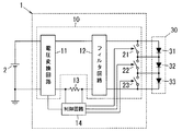
図1は本実施形態の点灯装置1の回路図である。点灯装置1は点灯回路10と制御回路14とを備え、光源30を点灯させる。
FIG. 1 is a circuit diagram of a lighting device 1 of the present embodiment. The lighting device 1 includes a
光源30は3つの光源群31,32,33を含む。光源群31,32,33の各々は、直列又は並列に接続された複数の発光ダイオードを有する。なお、光源群31,32,33は複数の発光ダイオードを有するものに限定されず、光源群31,32,33はそれぞれ1つの発光ダイオードで構成されてもよい。
The
点灯回路10は、電圧変換回路11と、フィルタ回路12と、スイッチ素子20とを備える。
The
電圧変換回路11は例えば昇圧チョッパ回路のようなスイッチング電源回路である。電圧変換回路11は、車両のバッテリのような直流電源2から供給される直流電圧を、制御回路14から入力される制御信号に応じてスイッチングすることによって、入力電圧の電圧値を制御信号に応じた電圧値に変換する。なお、電圧変換回路11は、昇圧チョッパ回路に限定されず、降圧チョッパ回路や昇降圧チョッパ回路などのDC−DCコンバータでもよい。
The
フィルタ回路12は、電圧変換回路11の出力電圧に含まれる高周波成分に損失を与えて、電圧変換回路11の出力電圧に含まれる高周波成分を抑制する。
The
フィルタ回路12の出力端子間にはスイッチ素子20と光源群31,32,33とが直列に接続されている。スイッチ素子20は例えばMOSFET(Metal Oxide Semiconductor Field Effect Transistor)のような半導体スイッチ素子からなる。スイッチ素子20は制御回路14から制御電極に入力される制御信号に応じて、オン/オフが切り替えられる。なお、スイッチ素子20はMOSFETに限定されず、IGBT(Insulated Gate Bipolar Transistor)などのバイポーラトランジスタでもよい。
A
制御回路14は、例えば外部回路(車両に搭載されたECU(Engine Control Unit)など)から入力される調光信号に基づいて、光源30(光源群31,32,33)を調光する。すなわち、制御回路14は、調光信号によって指示された調光レベルに基づいて振幅制御とPWM制御とを組み合わせた制御を行うことで、光源30を調光する。なお、制御回路14が光源30をPWM制御することによって、光源30が消灯する期間が発生するが、光源30が消灯していることを人の目では判別できない程度の周波数でPWM制御を行っているので、照明装置としての使用に実用上問題はない。
The
制御回路14は、光源30(光源群31,32,33)と直列に接続された抵抗13の両端電圧を検出しており、抵抗13の両端電圧から光源30に流れる電流の電流値(振幅)を測定する。制御回路14は、光源30に流れる電流の電流値を測定した結果に基づいて、電圧変換回路11に制御信号を出力し、電圧変換回路11にスイッチング動作を行わせることによって、電圧変換回路11の出力電圧を変化させる。すなわち、制御回路14は、電圧変換回路11の出力電圧を調整することによって、点灯回路10が光源30に供給する電流の電流値を制御(振幅制御)する。
The
制御回路14は、スイッチ素子20に制御信号を出力し、スイッチ素子20のオン/オフを制御する。制御回路14は、スイッチ素子20のオン/オフの期間を制御することによって、光源30に電流が流れるオン期間と光源30に電流が流れないオフ期間とのデューティ比を制御(PWM制御)する。
The
そして、制御回路14は、光源30の全調光範囲を複数に分割した複数の調光区分の各々において、以下のような調光制御を行う。制御回路14は、複数の調光区分の各々において、電流の電流値を最大値にした状態で光源30の明るさが当該調光区分の上限の明るさとなるようなデューティ比でPWM制御を行う。すなわち、複数の調光区分の各々において、PWM制御のデューティ比は一定値となる。そして、制御回路14は、複数の調光区分の各々において、一定のデューティ比でPWM制御を行っている状態で、光源30に流す電流の電流値を制御する振幅制御を行うことによって、光源30を例えば調光信号で指定された調光レベルで点灯させる。
Then, the
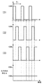
図2は、調光レベルが0%(全点灯状態)から100%(消灯状態)までの全調光範囲D0を3つの調光区分D1,D2,D3に分割し、各調光区分D1,D2,D3で振幅制御とPWM制御を行った場合の調光レベルとDC調光レベルの関係を示した図である。ここで、DC調光レベル(%)は光源30に流れる電流の電流値に比例した値となり、電流値が最大値であれば100%となり、電流値がゼロであれば0%となる。
FIG. 2 divides the entire dimming range D0 from the dimming level of 0% (all lit state) to 100% (extinguished state) into three dimming sections D1, D2, and D3. FIG. 6 is a diagram illustrating a relationship between a dimming level and a DC dimming level when amplitude control and PWM control are performed in D2 and D3. Here, the DC dimming level (%) is a value proportional to the current value of the current flowing through the
ところで、青色LEDと黄色蛍光体とを組み合わせて白色光を発光するような光源の場合、光源に流れる電流が低下すると、発光色が黄色みを帯びることが知られている。図2の制御例では、光源30に流れる電流の電流値が25%よりも低下すると発光色が変化するようなLEDを想定している。そして、発光ダイオードや回路部品のばらつきなどを考慮して、デューティ比を切り替えるときの電流値のしきい値を50%に設定している。
By the way, in the case of a light source that emits white light by combining a blue LED and a yellow phosphor, it is known that the emission color becomes yellowish when the current flowing through the light source decreases. In the control example of FIG. 2, an LED is assumed in which the emission color changes when the value of the current flowing through the
すなわち、制御回路14は、調光区分D1,D2において振幅制御によって電流値が50%まで低下すると、デューティ比を切り替えるような制御を行う。また、制御回路14は、人間の目でちらつきを確認できる周波数(100Hz程度)よりも十分高い周波数(例えば1kHz)にPWM制御の周波数を設定している。なお、制御回路14が、調光区分を切り替える前後で光源群31,32,33に流れる電流は変化するが、人間がちらつきを認識できる程度の時間(例えば10m秒程度)だけ出力電流を積分した値は調光区分を切り替える前後で同等である。よって、人間の目にはちらつきと認識されない。
That is, the
ここで、調光区分D1でのオンデューティ比は、電流値を最大値(DC調光レベルを100%)にした状態で光源30の明るさが調光区分D1の上限の明るさ(0%の調光レベル)となるようなオンデューティ比(100%)となる。したがって、調光区分D1では、制御回路14は、オンデューティ比を100%とした状態で、電流値を調整することによって光源30を調光する。制御回路14が、調光区分D1において調光レベルを50%まで低下させると、電流値が最大値の50%まで低下するので、調光レベルを50%よりも更に低下させる場合、制御回路14はオンデューティ比を切り替える。なお、光源30の調光レベルは、振幅制御によるDC調光レベル(電流値の最大値に対する比率(%))と、オンデューティ比(%)とを掛け合わせた値となる。
Here, the on-duty ratio in the dimming section D1 is such that when the current value is the maximum value (DC dimming level is 100%), the brightness of the
調光区分D2でのオンデューティ比は、電流値を最大値(DC調光レベルを100%)にした状態で光源30の明るさが調光区分D2の上限の明るさ(50%の調光レベル)となるようなオンデューティ比(50%)となる。したがって、調光区分D2では、制御回路14は、オンデューティ比を50%に制御した状態で、電流値を調整することによって光源30を調光する。制御回路14が、調光区分D2において調光レベルを75%まで低下させると、電流値が最大値の50%まで低下するので、調光レベルを75%よりも更に低下させる場合、制御回路14はオンデューティ比を切り替える。
The on-duty ratio in the dimming section D2 is such that the brightness of the
調光区分D3でのオンデューティ比は、電流値を最大値(DC調光レベルを100%)にした状態で光源30の明るさが調光区分D3の上限の明るさ(75%の調光レベル)となるようなオンデューティ比(25%)となる。したがって、調光区分D3では、制御回路14は、オンデューティ比を25%に制御した状態で、電流値を調整することによって光源30を調光する。ここで、制御回路14が、調光区分D3において調光レベルを93.7%まで低下させると、電流値が25%まで低下することになる。
The on-duty ratio in the light control section D3 is such that the brightness of the
光源30に流れる電流の振幅制御だけで光源30を調光する場合は、調光レベルを75%にすると、DC調光レベルが25%に達することになる。それに対して、本実施形態ではオンデューティ比を2回切り替えることによって、DC調光レベルが25%に低下するときの出力電流の調光レベルが93.7%まで大きくなっている。したがって、本実施形態の点灯装置1は、発光色が黄色みを帯びるのを抑制しつつ、より深い調光レベルまで調光制御を行うことが可能となる。
When dimming the
また、本実施形態の点灯装置1は、PWM制御と振幅制御とを組み合わせて調光制御を行っているので、PWM制御のみで調光する場合に比べてオンデューティ比を大きくでき、より深い調光レベルまで調光が可能になるから、調光制御の制御性が向上する。例えば、PWM制御だけで調光制御を行う場合に、PWM制御の周波数が1kHzであれば、調光レベルが93.7%となるときのオン時間は63μ秒となる。それに対して、本実施形態では調光区分D3でもオンデューティ比が25%であり、オン時間は250μ秒となる。したがって、PWM制御のみで調光する場合に比べてオン時間が4倍程度になるから、調光制御の制御性が向上する。 Further, since the lighting device 1 of the present embodiment performs the dimming control by combining the PWM control and the amplitude control, the on-duty ratio can be increased and the deeper dimming can be performed as compared with the case where the dimming is performed only by the PWM control. Since dimming is possible up to the light level, controllability of dimming control is improved. For example, in the case where the dimming control is performed only by the PWM control and the frequency of the PWM control is 1 kHz, the ON time when the dimming level becomes 93.7% is 63 μs. On the other hand, in the present embodiment, the on-duty ratio is 25% even in the dimming section D3, and the on-time is 250 μs. Therefore, the on-time is about four times as long as the case where the light control is performed only by the PWM control, and the controllability of the light control is improved.
なお、図2の例では、制御回路14が、全調光範囲D0を3つの調光区分D1,D2,D3に分割しているが、調光区分の数は3つに限定されず、全調光範囲を2つの調光区分に分割してもよいし、全調光範囲を4つ以上の調光区分に分割してもよい。調光区分の数を増やせば、光源30に流れる電流の振幅の下限値を高くできる一方、オンデューティ比は小さくなるから、電流振幅の下限値とオンデューティ比を考慮して調光区分の数や各調光区分の調光レベルを適宜設定すればよい。
In the example of FIG. 2, the
本実施形態の点灯装置1は、光源30に電流を供給する点灯回路10と、光源30を調光する制御回路14とを備える。制御回路14は、点灯回路10が光源30に供給する電流の電流値を制御する振幅制御と、光源30に電流が流れるオン期間と光源30に電流が流れないオフ期間とのデューティ比を制御するPWM制御とを行うことによって、光源30を調光する。制御回路14は、光源30の全調光範囲を複数に分割した複数の調光区分の各々で、電流の電流値を最大値にした状態で光源の明るさが当該調光区分の上限の明るさとなるようなデューティ比でPWM制御を行い、かつ、電流の電流値を制御する振幅制御を行う。
The lighting device 1 of the present embodiment includes a
これにより、振幅制御のみで調光する場合に比べて、光源30に流れる電流の電流値が大きくなり、光源30の発光色が黄色みを帯びにくくなり、発光色の色の変化を抑制できる。また、PWM制御のみで調光する場合に比べて、オンデューティ比が大きくなるから、スルーレートの影響が小さくなり、調光制御の制御性を向上することができる。
As a result, the current value of the current flowing through the
本実施形態において、制御回路14は、複数の調光区分の各々において、あらかじめ設定された最小値以上の電流範囲で振幅制御を行ってもよい。
In the present embodiment, the
これにより、振幅制御を行う場合に、光源30に流れる電流の電流値を最小値以上の電流範囲に制限することができる。例えば光源30が発光ダイオードの場合、発光色が黄色みを帯びるような電流値よりも高い電流値に最小値を設定しておけば、発光ダイオードの発光色が変化するのを抑制できる。
Thus, when performing the amplitude control, the current value of the current flowing through the
(実施形態2)
本実施形態の点灯装置1の回路図を図3に示す。なお、実施形態1の点灯装置1と共通する構成要素には同一の符号を付して、その説明は省略する。
(Embodiment 2)
FIG. 3 shows a circuit diagram of the lighting device 1 of the present embodiment. Note that the same components as those of the lighting device 1 of the first embodiment are denoted by the same reference numerals, and description thereof will be omitted.
実施形態1の点灯装置1では、3つの光源群31,32,33をひとまとめに点灯/消灯しているが、本実施形態では3つの光源群31,32,33の点灯/消灯を個別に制御する。
In the lighting device 1 of the first embodiment, the three
光源30は3つの光源群31,32,33を含み、3つの光源群31,32,33はフィルタ回路12の出力端子間に直列に接続されている。光源群31,32,33の各々は、例えば直列に接続された同数の発光ダイオードを有している。なお、光源群31,32,33の各々は、並列に接続された同数の発光ダイオードを有してもよい。また、光源群31,32,33は複数の発光ダイオードを有するものに限定されず、光源群31,32,33はそれぞれ1つの発光ダイオードで構成されてもよい。
The
光源群31,32,33にはそれぞれスイッチ素子21,22,23が並列に接続されている。
The
スイッチ素子21,22,23は例えばMOSFET(Metal Oxide Semiconductor Field Effect Transistor)のような半導体スイッチ素子からなる。スイッチ素子21,22,23はそれぞれ制御回路14から制御電極に入力される制御信号に応じて、個別にオン/オフが切り替えられる。なお、スイッチ素子21,22,23はMOSFETに限定されず、IGBTなどのバイポーラトランジスタでもよい。
Each of the
制御回路14は、振幅制御とPWM制御とを組み合わせた制御を行って光源群31,32,33を調光する。
The
制御回路14は、光源群31,32,33と直列に接続された抵抗13の両端電圧を検出しており、抵抗13の両端電圧から光源群31,32,33に流れる電流の電流値を測定する。制御回路14は、光源群31,32,33に流れる電流の電流値を測定した結果に基づいて電圧変換回路11に制御信号を出力し、電圧変換回路11にスイッチング動作を行わせることによって、電圧変換回路11の出力電圧を変化させる。すなわち、制御回路14は、電圧変換回路11の出力電圧を調整することによって、点灯回路10が光源群31,32,33に供給する電流の電流値を制御(振幅制御)する。
The
制御回路14は、スイッチ素子21,22,23のそれぞれに制御信号を出力して、スイッチ素子21,22,23のオン/オフをそれぞれ別個に制御する。制御回路14は、光源群31,32,33に電流が流れるオン期間と、光源群31,32,33に電流が流れないオフ期間とのオンデューティ比を制御するPWM制御を行う。
The
そして、制御回路14は、光源群31,32,33の全調光範囲D0を、光源群31,32,33の数(本実施形態では3つ)で等分した3つの調光区分D1,D2,D3の各々において、以下のような調光制御を行う。
Then, the
制御回路14は、調光区分D1,D2,D3の各々において、電流値を最大値にした状態で光源群31,32,33の明るさが当該調光区分の上限の明るさとなるようなオンデューティ比でPWM制御を行う。すなわち、調光区分D1,D2,D3の各々において、PWM制御のオンデューティ比は一定値となる。そして、制御回路14は、調光区分D1,D2,D3の各々において、一定のオンデューティ比でPWM制御を行い、かつ、光源群31,32,33に流す電流値を振幅制御することによって、光源群31,32,33を調光する。なお、制御回路14は、例えば外部回路から入力される調光信号に応じた振幅制御及びPWM制御を行うことで、調光信号に応じた調光レベルで光源群31,32,33を点灯させる。
In each of the dimming sections D1, D2, and D3, the
図4は、調光区分D1,D2,D3の各々において、電流の振幅制御とPWM制御とを行った場合の調光レベルと電流振幅との関係を示した図である。 FIG. 4 is a diagram illustrating a relationship between the dimming level and the current amplitude when the current amplitude control and the PWM control are performed in each of the dimming sections D1, D2, and D3.
本実施形態では全調光範囲D0を3等分しているので、調光区分D1は調光レベルが0%から33.33%まで、調光区分D2は調光レベルが33.33%から66.67%まで、調光区分D3は調光レベルが66.67%から100%までの調光範囲となる。 In this embodiment, since the entire light control range D0 is divided into three equal parts, the light control level of the light control section D1 is 0% to 33.33%, and the light control level of the light control section D2 is 33.33%. Up to 66.67%, the dimming section D3 has a dimming range in which the dimming level is from 66.67% to 100%.
制御回路14は、光源群31,32,33を全点灯状態から調光する場合、調光区分D1においては、オンデューティ比を100%とした状態で、電流の振幅制御を行う。
When dimming the
制御回路14は、調光レベルを33.33%よりも更に大きく(明るさを暗く)する場合、オンデューティ比を切り替える。すなわち、制御回路14は、調光区分D2でのオンデューティ比を、電流値を最大値にした状態で光源30の明るさが調光区分D2の上限の明るさ(33.33%の調光レベル)となるようなオンデューティ比(66.67%)に設定する。そして、制御回路14は、調光区分D2においては、オンデューティ比を66.67%とした状態で、電流の振幅制御を行うことによって、光源群31,32,33を調光する。
The
図5は、調光区分D2において調光レベルを33.33%とする場合に、光源群31,32,33にそれぞれ流れる電流I31,I32,I33と、出力光の明るさとの関係を示したグラフである。
FIG. 5 shows the relationship between the currents I31, I32, and I33 flowing through the
制御回路14は、光源群31,32,33を点灯させるタイミングを、PWM制御の1周期T1を光源群31,32,33の数で分割した時間(T1/3)ずつずらしている。図5の例では、制御回路14は、光源群31,32,33の順番で、光源群31,32,33を点灯させる。ここで、光源群31が点灯し始めるタイミングをタイミングt1とし、タイミングt1から時間(T1/3)が経過したタイミングをタイミングt2とし、タイミングt2から時間(T1/3)が経過したタイミングをタイミングt3とする。
The
タイミングt1では、光源群31が点灯し始め、光源群32が消灯し、光源群33は点灯状態を継続する。タイミングt1とタイミングt2との間では、光源群31,33が点灯し、光源群32が消灯する。タイミングt2では、光源群31は点灯状態を継続し、光源群32が点灯し始め、光源群33が消灯する。タイミングt2とタイミングt3との間では、光源群31,32が点灯し、光源群33が消灯する。タイミングt3では、光源群31が消灯し、光源群32が点灯状態を継続し、光源群33が点灯し始める。タイミングt3とタイミングt1との間では、光源群32,33が点灯し、光源群31が消灯する。
At the timing t1, the
すなわち、調光区分D2においてはオンデューティ比が66.67%に設定され、光源群31,32,33が点灯し始めるタイミングを時間(T1/3)ずつずらしているので、3つの光源群31,32,33のうちの2つが常に点灯する。したがって、全ての光源群31,32,33が同時に点灯する場合の明るさを300%とすると、調光区分D2での明るさは200%となり、明るさの時間的な変化が低減される。
That is, in the dimming section D2, the on-duty ratio is set to 66.67%, and the timing at which the
また、制御回路14は、3つの光源群31,32,33のうちの2つを常に点灯させるが、光源群31,32,33を点灯し始めるタイミングをずらして、インターリーブ動作としており、オーバーシュート量やアンダーシュート量やノイズレベルを低減できる。
Further, the
また、制御回路14は、調光レベルを66.67%よりも更に大きくする場合、オンデューティ比を切り替える。なお、調光区分D2において調光レベルが66.67%となるときの、DC調光レベルは50%である。
The
制御回路14は、調光区分D3でのオンデューティ比を、電流値を最大値にした状態で光源30の明るさが調光区分D3の上限の明るさ(66.67%の調光レベル)となるようなオンデューティ比(33.33%)に設定する。そして、制御回路14は、調光区分D3においては、オンデューティ比を66.67%とした状態で、電流の振幅制御を行うことによって、光源群31,32,33を調光する。
The
図6は、調光区分D3において調光レベルを66.67%とする場合に、光源群31,32,33にそれぞれ流れる電流I31,I32,I33と、出力光の明るさとの関係を示したグラフである。なお、制御回路14が光源群31,32,33を点灯し始めるタイミングは図5の動作例と同様である。
FIG. 6 shows the relationship between the currents I31, I32, and I33 flowing through the
タイミングt1では、光源群31が点灯し始め、光源群32が消灯し、光源群33は消灯状態を継続する。タイミングt1とタイミングt2との間では、光源群31が点灯し、光源群32,33が消灯する。タイミングt2では、光源群31は消灯し、光源群32が点灯し始め、光源群33が消灯状態を維持する。タイミングt2とタイミングt3との間では、光源群32が点灯し、光源群31,33が消灯する。タイミングt3では、光源群31が消灯状態を維持し、光源群32が消灯し、光源群33が点灯し始める。タイミングt3とタイミングt1との間では、光源群33が点灯し、光源群31,32が消灯する。
At the timing t1, the
すなわち、調光区分D3においてはオンデューティ比が33.33%に設定され、光源群31,32,33が点灯し始めるタイミングを時間(T1/3)ずつずらしているので、3つの光源群31,32,33のうちの1つだけが常に点灯することになる。したがって、全ての光源群31,32,33が同時に点灯する場合の明るさを300%とすると、調光区分D3での明るさは100%となり、明るさの時間的な変化が低減される。
That is, in the light control section D3, the on-duty ratio is set to 33.33%, and the timing at which the
なお、本実施形態では3つの光源群31,32,33を備える場合について説明したが、光源群の数は3つに限定されない。光源群の数が4つの場合の調光動作を図7に基づいて説明する。
In the present embodiment, the case where three
光源群の数が4つの場合、制御回路14は、全調光範囲D0を4つの調光区分D1〜D4に4等分する。調光区分D1は調光レベルが0%から25%まで、調光区分D2は調光レベルが25%から50%まで、調光区分D3は調光レベルが50%から75%まで、調光区分D4は調光レベルが75%から100%までの調光範囲となる。
When the number of light source groups is four, the
制御回路14は、4つの光源群を全点灯状態から調光する場合、調光区分D1においては、オンデューティ比を100%とした状態で、電流の振幅制御を行う。
When dimming the four light source groups from the fully lit state, the
制御回路14は、調光レベルを25%よりも更に大きくする場合、オンデューティ比を切り替える。すなわち、制御回路14は、調光区分D2でのオンデューティ比を、電流値を最大値にした状態で光源30の明るさが調光区分D2の上限の明るさ(25%の調光レベル)となるようなオンデューティ比(75%)に設定する。そして、制御回路14は、調光区分D2においては、オンデューティ比を75%とした状態で、電流の振幅制御を行うことによって、4つの光源群を調光する。
The
制御回路14は、調光レベルを50%よりも更に大きくする場合、オンデューティ比を切り替える。なお、調光区分D2において調光レベルが50%になるときのDC調光レベルは66.6%である。
The
制御回路14は、調光区分D3でのオンデューティ比を、電流値を最大値にした状態で光源30の明るさが調光区分D3の上限の明るさ(50%の調光レベル)となるようなオンデューティ比(50%)に設定する。そして、制御回路14は、調光区分D3においては、オンデューティ比を50%とした状態で、電流の振幅制御を行うことによって、4つの光源群を調光する。
The
制御回路14は、調光レベルを75%よりも更に大きくする場合、オンデューティ比を切り替える。なお、調光区分D3において調光レベルが75%になるときのDC調光レベルは50%である。
The
制御回路14は、調光区分D4でのオンデューティ比を、電流値を最大値にした状態で光源30の明るさが調光区分D4の上限の明るさ(75%の調光レベル)となるようなオンデューティ比(25%)に設定する。そして、制御回路14は、調光区分D4においては、オンデューティ比を25%とした状態で、電流の振幅制御を行うことによって、4つの光源群を調光する。
The
ここで、制御回路14が、4つの光源群を点灯し始めるタイミングを、PWM制御の1周期T1を光源群の数で分割した時間(T1/4)ずつずらすようにすれば、時間的な明るさの変化を低減できる。
Here, if the
なお、光源群の数がn(nは2以上の整数)の場合、制御回路14は、全調光範囲D0をn個の調光区分D1〜Dnに等分し、各々の調光区分においてオンデューティ比を一定値として、電流の振幅制御を行うことによって光源群を調光する。
When the number of light source groups is n (n is an integer of 2 or more), the
ここで、k(k=1,2…n)番目の調光区分Dkにおけるオンデューティ比DT1は次の式(1)で表される。 Here, the on-duty ratio DT1 in the kth (k = 1, 2,..., N) th dimming section Dk is represented by the following equation (1).
DT1=((n−(k−1))/n)×100(%)
そして、制御回路14は、n個の光源群が点灯し始めるタイミングを、PWM制御の1周期T1をn等分した時間ずつずらせば、出力光の明るさの時間的な変化を低減することができる。
DT1 = ((n− (k−1)) / n) × 100 (%)
Then, the
本実施形態の点灯装置1において、点灯回路10は、光源30が有する複数の光源群(光源群31,32,33)に電流を供給する。制御回路14は、全調光範囲を複数の光源群の数で等分した複数の調光区分の各々において、光源群ごとに振幅制御とPWM制御を行う。制御回路14は、複数の光源群にそれぞれ電流が流れ始めるタイミングを、PWM制御の1周期を光源群の数で等分した時間差だけずらすようにPWM制御を行う。
In the lighting device 1 of the present embodiment, the
これにより、点灯している光源群の数が時間経過に関係なく一定の数となるから、出力光の明るさの時間的な変化を低減できる。 Thus, the number of light source groups that are turned on becomes a constant number regardless of the passage of time, so that a temporal change in the brightness of the output light can be reduced.
(実施形態3)
本実施形態の点灯装置1の回路図を図8に示す。
(Embodiment 3)
FIG. 8 shows a circuit diagram of the lighting device 1 of the present embodiment.
本実施形態の点灯装置1は2つの点灯回路10A,10Bを備え、2つの点灯回路10A,10Bがそれぞれ光源30A,30Bに電力を供給する。2つの点灯回路10A,10Bの各々は電圧変換回路11とフィルタ回路12とを有している。なお、実施形態1の点灯装置1と共通する構成要素には同一の符号を付して、その説明は省略する。
The lighting device 1 of the present embodiment includes two
また、本実施形態の点灯装置1では、2つの点灯回路10A,10Bの動作を1つの制御回路14が制御する。制御回路14には、光源30Aと直列に接続された抵抗13Aの両端電圧と、光源30Bと直列に接続された抵抗13Bの両端電圧とが入力される。
Further, in the lighting device 1 of the present embodiment, the operation of the two
制御回路14は、実施形態1と同様に、PWM制御と振幅制御とを組み合わせた調光制御を行う。図9は本実施形態の点灯装置の調光動作を説明するグラフである。本実施形態では全調光範囲D0を2つの調光区分D1,D2に等分しており、調光区分D1の調光レベルは0%から50%(図9のL2)までの調光範囲であり、調光区分D2の調光レベルは50%(L2)から100%までの調光範囲である。
The
制御回路14は、調光区分D1,D2の各々において、オンデューティ比が一定のPWM制御を行い、かつ、電流の振幅を制御する振幅制御を行うことによって、光源30A,30Bを調光する。制御回路14は、調光区分D1,D2でのオンデューティ比を、電流値を最大値にした状態で、光源30A,30Bの明るさが当該調光区分の上限の明るさとなるようなオンデューティ比に設定する。すなわち、制御回路14は、調光区分D1のオンデューティ比を、電流値を最大値にした状態で、光源30A,30Bの明るさが調光区分D1の上限の明るさ(調光レベルが0%)となるようなオンデューティ比(例えば100%)に設定する。また、制御回路14は、調光区分D2のオンデューティ比を、電流値を最大値にした状態で、光源30A,30Bの明るさが調光区分D2の上限の明るさ(調光レベルが50%)となるようなオンデューティ比(例えば50%)に設定する。
The
したがって、制御回路14は、調光区分D1では、100%のオンデューティ比でPWM制御を行い、かつ、電流の振幅を制御する振幅制御を行うことによって、光源30A,30Bを調光する。制御回路14は、調光区分D2では、50%のオンデューティ比でPWM制御を行い、かつ、電流の振幅を制御する振幅制御を行うことによって、光源30A,30Bを調光する。
Therefore, in the dimming section D1, the
さらに、本実施形態では、制御回路14が調光区分D1,D2の境界となる調光レベルにヒステリシスを設定している。ヒステリシスを設定するとは、調光区分Dk(kは1以上の整数)からより暗い調光区分D(k+1)に切り替わる場合の境界の第1調光レベルよりも、調光区分D(k+1)から調光区分Dkに切り替わる場合の境界の第2調光レベルを明るくすることを意味する。本実施形態では、調光区分D1からより暗い調光区分D2に切り替わる場合の境界の第1調光レベルL1(例えば60%)よりも、調光区分D2から調光区分D1に切り替わる場合の境界の第2調光レベルL2(例えば50%)の方を明るくしている。これにより、調光区分D1,D2の境界の調光レベル付近で、PWM制御のオンデューティ比及び振幅制御のDC調光レベルが調光区分D1での値と調光区分D2での値との間で頻繁に切り替わりにくくなり、光源30A,30Bに流れる電流が安定する。なお、ヒステリシスの設定は上記の例に限定されず、調光区分D1,D2の境界の調光レベルが50%の場合に、第1調光レベルL1を(50+x1)%、第2調光レベルL2を(50−x2)%に設定してもよく、x1,x2の値は適宜変更が可能である。
Further, in the present embodiment, the
上述のように、制御回路14は、複数の調光区分の境界となる調光レベルにヒステリシスを設定してもよい。
As described above, the
これにより、調光区分の境界付近で、PWM制御のオンデューティ比及び振幅制御の振幅が頻繁に切り替わりにくくなり、制御が安定する。 This makes it difficult for the on-duty ratio of the PWM control and the amplitude of the amplitude control to be frequently switched near the boundary of the dimming section, and the control is stabilized.
なお、実施形態1,2で説明した点灯装置1において、制御回路14が複数の調光区分の境界となる調光レベルにヒステリシスを設定してもよく、複数の調光区分の境界の調光レベル付近で、オンデューティ比やDC調光レベルが頻繁に切り替わりにくくなる。
In the lighting device 1 described in the first and second embodiments, the
(実施形態4)
実施形態3で説明した点灯装置1を用いた車両用照明装置40の実施形態について図10を参照して説明する。なお、図10の説明では、図10に矢印で示した上下、前後の各方向を基準として説明を行う。
(Embodiment 4)
An embodiment of a
車両用照明装置40は、例えば車両の前照灯を点灯させる照明装置である。
The
この車両用照明装置40の本体41は、前面(車両に取り付けられた状態で車両の前方を向く面)が開口したケース42と、ケース42の開口部分を塞ぐように取り付けられた透光性のカバー43とを有する。
The
本体41の内部には、光源30Aを構成する3つの光源群34と、光源30Bを構成する2つの光源群35とが収納されている。本実施形態の車両用照明装置40は前照灯装置であり、光源30Aは走行用前照灯(ハイビーム)として用いられ、光源30Bはすれ違い前照灯(ロービーム)として用いられる。なお、光源群34,35はそれぞれ複数のLEDで構成されてもよいし、1つのLEDで構成されてもよい。
Inside the
本体41の内部には、3つの光源群34がそれぞれ取り付けられる3つの取付台44と、2つの光源群35がそれぞれ取り付けられる2つの取付台45とが配置されている。
Inside the
複数の取付台44,45はそれぞれ金属材料により側面視の形状がL形に形成されている。光源群34が取り付けられる取付台44には、配光を制御するレンズ46と、光源群34の光を反射してレンズ46に入射させる反射板47とが取り付けられている。光源群35が取り付けられる取付台45には、配光を制御するレンズ46が取り付けられている。
Each of the plurality of mounting
ケース42の下部には点灯装置1が取り付けられており、光源群34,35と点灯装置1とはケーブル48を介して電気的に接続されている。
The lighting device 1 is attached to a lower portion of the
なお、車両用照明装置40は実施形態3で説明した点灯装置1を備えるものに限定されず、請求項1又は2で説明した点灯装置1を備えてもよい。
Note that the
上述のように本実施形態の車両用照明装置40は車両に取り付けられる本体41を備え、本体41に点灯装置1と光源(光源群34,35)とが保持されている。
As described above, the
本実施形態の車両用照明装置40は、実施形態1〜3のいずれかで説明した点灯装置1を備えているので、調光制御の制御性を向上することができる。
Since the
また、図11は本実施形態の車両用照明装置40を備えた車両50の前部を示す斜視図である。
FIG. 11 is a perspective view showing a front portion of a
本実施形態の車両50は前照灯装置として一対の車両用照明装置40を備え、車体51の前部の左側及び右側に車両用照明装置40が搭載されている。一対の車両用照明装置40の点灯装置1は、車内の運転席に設けられたスイッチの操作や、車両50に取り付けられた明るさセンサによって検出される周囲の明るさなどに応じて、光源30A,30Bを点灯(全点灯、調光点灯)又は消灯させる。
The
また、左右の車両用照明装置40の点灯装置1は通信バス3を介して通信を行い、光源30A,30Bを点灯又は消灯させるタイミングを同期させることができる。左側の車両用照明装置40が備える光源30A,30Bの配光と、右側の車両用照明装置40が備える光源30A,30Bの配光とは一部が重なっている。左右の車両用照明装置40の点灯装置1が、一方の車両用照明装置40の光源30A,30Bが消灯するタイミングで、他方の車両用照明装置40の光源30A,30Bを点灯させるように制御すれば、配光が重なる範囲で時間的な明るさの変化を低減できる。
Further, the lighting devices 1 of the left and right
上述のように本実施形態の車両用照明装置40は、車両50(車体51)の左側及び右側にそれぞれ取り付けられる一対の本体41を備えている。一対の本体41の各々には、実施形態1〜3のいずれかで説明した点灯装置1と、光源(光源30,30A,30B)とが保持されている。
As described above, the
本実施形態の車両用照明装置40は、実施形態1〜3のいずれかで説明した点灯装置1を備えているので、調光制御の制御性を向上することができる。
Since the
また、本実施形態の車両50は、車両用照明装置40と、車両用照明装置40が取り付けられる車体51とを備える。
Further, the
本実施形態の車両50は、本実施形態の車両用照明装置40を備えているので、調光制御の制御性を向上することができる。
Since the
1 点灯装置
10,10A,10B 点灯回路
14 制御回路
30,30A,30B 光源
31〜35 光源群
40 車両用照明装置
41 本体
50 車両
51 車体
D0 全調光範囲
D1〜D4 調光区分
L1 第1調光レベル
L2 第2調光レベル
DESCRIPTION OF SYMBOLS 1
Claims (7)
前記光源を調光する制御回路とを備え、
前記制御回路は、前記点灯回路が前記光源に供給する電流の電流値を制御する振幅制御と、前記光源に電流が流れるオン期間と前記光源に電流が流れないオフ期間とのデューティ比を制御するPWM制御とを行い、
前記光源は、複数の光源群を有し、
前記制御回路は、前記光源の全調光範囲を複数に分割した複数の調光区分の各々で、前記光源群ごとに、前記電流の電流値を最大値にした状態で前記光源群の明るさが当該調光区分の上限の明るさとなるようなデューティ比でPWM制御を行い、かつ、前記光源群に流れる前記電流の電流値を制御する振幅制御を行うことによって、前記光源を調光するように構成され、
前記点灯回路は、前記光源が有する複数の光源群に電流を供給し、
前記制御回路は、前記全調光範囲を前記複数の光源群の数で等分した前記複数の調光区分の各々において、前記光源群ごとに前記振幅制御と前記PWM制御を行い、
前記制御回路は、前記複数の光源群にそれぞれ電流が流れ始めるタイミングを、前記PWM制御の1周期を前記光源群の数で等分した時間差だけずらすように前記PWM制御を行うことを特徴とする点灯装置。 A lighting circuit for supplying current to the light source;
A control circuit for dimming the light source,
The control circuit controls an amplitude control for controlling a current value of a current supplied to the light source by the lighting circuit, and controls a duty ratio between an ON period in which current flows to the light source and an OFF period in which no current flows to the light source. Perform PWM control and
The light source has a plurality of light source groups,
In each of the plurality of dimming sections obtained by dividing the entire dimming range of the light source into a plurality, the control circuit controls the brightness of the light source group in a state where the current value of the current is a maximum value for each of the light source groups. Performs PWM control at a duty ratio such that the upper limit brightness of the dimming section is obtained, and performs amplitude control for controlling a current value of the current flowing through the light source group, thereby dimming the light source. Is composed of
The lighting circuit supplies a current to a plurality of light source groups included in the light source,
The control circuit performs the amplitude control and the PWM control for each light source group in each of the plurality of dimming sections obtained by equally dividing the entire dimming range by the number of the plurality of light source groups,
The control circuit performs the PWM control such that a timing at which a current starts flowing through each of the plurality of light source groups is shifted by a time difference obtained by equally dividing one cycle of the PWM control by the number of the light source groups. Lighting device.
前記光源を調光する制御回路とを備え、 A control circuit for dimming the light source,
前記点灯回路は、前記光源が有する複数の光源群に電流を供給し、 The lighting circuit supplies a current to a plurality of light source groups included in the light source,
前記制御回路は、前記点灯回路が前記光源に供給する電流の電流値を制御する振幅制御 The control circuit controls an amplitude value of a current supplied from the lighting circuit to the light source.
と、前記光源に電流が流れるオン期間と前記光源に電流が流れないオフ期間とのデューティ比を制御するPWM制御とを行い、Performing PWM control for controlling a duty ratio between an ON period in which a current flows through the light source and an OFF period in which no current flows through the light source;
前記制御回路は、前記光源の全調光範囲を前記複数の光源群の数で等分した複数の調光区分の各々において、前記光源群ごとに、前記電流の電流値を最大値にした状態で前記光源群の明るさが当該調光区分の上限の明るさとなるようなデューティ比でPWM制御を行い、かつ、前記光源群に流れる前記電流の電流値を制御する振幅制御を行うことによって、前記光源を調光するように構成され、 The control circuit is configured to set the current value of the current to the maximum value for each of the light source groups in each of the plurality of dimming sections in which the entire dimming range of the light source is equally divided by the number of the plurality of light source groups. By performing PWM control at a duty ratio such that the brightness of the light source group becomes the brightness of the upper limit of the dimming section, and by performing amplitude control to control the current value of the current flowing through the light source group, Configured to dimming the light source;
前記制御回路は、前記複数の光源群にそれぞれ電流が流れ始めるタイミングを、前記PWM制御の1周期を前記光源群の数で等分した時間差だけずらすように前記PWM制御を行うことを特徴とする点灯装置。 The control circuit performs the PWM control such that a timing at which a current starts flowing through each of the plurality of light source groups is shifted by a time difference obtained by equally dividing one cycle of the PWM control by the number of the light source groups. Lighting device.
前記本体に、請求項1〜4のいずれか1項に記載の点灯装置と、前記光源とが保持されたことを特徴とする車両用照明装置。 A lighting device for a vehicle, wherein the lighting device according to any one of claims 1 to 4 and the light source are held in the main body.
前記一対の本体の各々に、請求項1〜4のいずれか1項に記載の点灯装置と、前記光源とが保持されたことを特徴とする車両用照明装置。 A lighting device for a vehicle, wherein the lighting device according to any one of claims 1 to 4 and the light source are held in each of the pair of main bodies.
Priority Applications (4)
| Application Number | Priority Date | Filing Date | Title |
|---|---|---|---|
| JP2015137798A JP6667154B2 (en) | 2015-07-09 | 2015-07-09 | Lighting device, vehicle lighting device, and vehicle using the same |
| US15/204,538 US9623791B2 (en) | 2015-07-09 | 2016-07-07 | Lighting device, vehicle illumination device, and vehicle |
| DE102016112550.4A DE102016112550A1 (en) | 2015-07-09 | 2016-07-08 | LIGHTING ASSEMBLY, VEHICLE LIGHTING DEVICE AND VEHICLE |
| CN201610538994.1A CN106341920B (en) | 2015-07-09 | 2016-07-08 | Lamp device, Vehicular illumination device and vehicle |
Applications Claiming Priority (1)
| Application Number | Priority Date | Filing Date | Title |
|---|---|---|---|
| JP2015137798A JP6667154B2 (en) | 2015-07-09 | 2015-07-09 | Lighting device, vehicle lighting device, and vehicle using the same |
Publications (2)
| Publication Number | Publication Date |
|---|---|
| JP2017021953A JP2017021953A (en) | 2017-01-26 |
| JP6667154B2 true JP6667154B2 (en) | 2020-03-18 |
Family
ID=57583683
Family Applications (1)
| Application Number | Title | Priority Date | Filing Date |
|---|---|---|---|
| JP2015137798A Active JP6667154B2 (en) | 2015-07-09 | 2015-07-09 | Lighting device, vehicle lighting device, and vehicle using the same |
Country Status (4)
| Country | Link |
|---|---|
| US (1) | US9623791B2 (en) |
| JP (1) | JP6667154B2 (en) |
| CN (1) | CN106341920B (en) |
| DE (1) | DE102016112550A1 (en) |
Families Citing this family (9)
| Publication number | Priority date | Publication date | Assignee | Title |
|---|---|---|---|---|
| JP6215882B2 (en) * | 2015-08-27 | 2017-10-18 | 株式会社小糸製作所 | Vehicle lamp and vehicle lamp system |
| KR102202125B1 (en) * | 2017-06-02 | 2021-01-13 | 현대모비스 주식회사 | Apparatus and method for controlling light distribution using steering information |
| US10123384B1 (en) * | 2017-09-22 | 2018-11-06 | Linear Technology Holding, LLC | LED dimming |
| US10201052B1 (en) * | 2017-09-22 | 2019-02-05 | Linear Technology Holding, LLC | LED dimming |
| JP7000840B2 (en) * | 2017-12-19 | 2022-01-19 | 株式会社デンソー | Front lighting device for vehicles |
| JP7024388B2 (en) * | 2017-12-22 | 2022-02-24 | 株式会社デンソー | Front lighting device for vehicles, disconnection detection method |
| JP6904283B2 (en) * | 2018-03-12 | 2021-07-14 | 株式会社オートネットワーク技術研究所 | In-vehicle DCDC converter |
| US11116055B2 (en) * | 2018-12-27 | 2021-09-07 | Lumileds Llc | Time slicing method for multi-channel color tuning using a single current source input |
| TWI757794B (en) * | 2020-07-15 | 2022-03-11 | 群光電能科技股份有限公司 | Lamp group switching control device |
Family Cites Families (21)
| Publication number | Priority date | Publication date | Assignee | Title |
|---|---|---|---|---|
| JP4496812B2 (en) | 2004-03-18 | 2010-07-07 | 東芝ライテック株式会社 | LED lighting device |
| ES2298987T3 (en) * | 2005-02-02 | 2008-05-16 | Patent-Treuhand-Gesellschaft Fur Elektrische Gluhlampen Mbh | METHOD AND SYSTEM TO DIMATE SOURCES OF LIGHT. |
| JP2007234522A (en) * | 2006-03-03 | 2007-09-13 | Minebea Co Ltd | Discharge lamp lighting device |
| JP2007294169A (en) * | 2006-04-24 | 2007-11-08 | Toshiba Lighting & Technology Corp | Led lighting system |
| JP4943892B2 (en) * | 2007-02-23 | 2012-05-30 | パナソニック株式会社 | Light control device and lighting fixture using the same |
| JP4943891B2 (en) * | 2007-02-23 | 2012-05-30 | パナソニック株式会社 | Light control device and lighting fixture using the same |
| JP2009123681A (en) | 2007-10-25 | 2009-06-04 | Panasonic Electric Works Co Ltd | Led dimming apparatus |
| JP2011108670A (en) | 2007-10-25 | 2011-06-02 | Panasonic Electric Works Co Ltd | Led dimming apparatus |
| US8115419B2 (en) * | 2008-01-23 | 2012-02-14 | Cree, Inc. | Lighting control device for controlling dimming, lighting device including a control device, and method of controlling lighting |
| JP5160259B2 (en) * | 2008-02-08 | 2013-03-13 | 株式会社小糸製作所 | Vehicle headlamp device |
| US9572208B2 (en) * | 2008-08-29 | 2017-02-14 | Philips Lighting Holding B.V. | LED lighting system with accurate current control |
| JP5480671B2 (en) | 2010-03-03 | 2014-04-23 | パナソニック株式会社 | LED lighting device |
| US9942954B2 (en) * | 2010-05-14 | 2018-04-10 | Lumastream Canada Ulc | Method and system for controlling solid state lighting via dithering |
| JP5538078B2 (en) | 2010-06-11 | 2014-07-02 | 三菱電機株式会社 | LED power supply |
| JP5618220B2 (en) * | 2010-11-12 | 2014-11-05 | 東芝ライテック株式会社 | LED lighting device and LED lighting device |
| JP5942256B2 (en) * | 2012-06-08 | 2016-06-29 | パナソニックIpマネジメント株式会社 | Lighting device and lighting apparatus |
| JP2013258003A (en) | 2012-06-12 | 2013-12-26 | Koito Mfg Co Ltd | Semiconductor light source control device |
| DE102014111085A1 (en) * | 2013-08-20 | 2015-02-26 | Panasonic Corporation | Illumination assembly and lighting device using the same |
| DE102014111080A1 (en) * | 2013-08-20 | 2015-02-26 | Panasonic Corporation | Illumination assembly and lighting device using the same |
| JP6063853B2 (en) * | 2013-11-29 | 2017-01-18 | ミネベア株式会社 | LED driving device and lighting apparatus |
| CN107548515B (en) * | 2015-04-24 | 2019-10-15 | 应用材料公司 | Processing set group comprising flow insulated ring |
-
2015
- 2015-07-09 JP JP2015137798A patent/JP6667154B2/en active Active
-
2016
- 2016-07-07 US US15/204,538 patent/US9623791B2/en active Active
- 2016-07-08 CN CN201610538994.1A patent/CN106341920B/en active Active
- 2016-07-08 DE DE102016112550.4A patent/DE102016112550A1/en not_active Withdrawn
Also Published As
| Publication number | Publication date |
|---|---|
| DE102016112550A1 (en) | 2017-01-12 |
| CN106341920B (en) | 2019-10-29 |
| US9623791B2 (en) | 2017-04-18 |
| US20170008447A1 (en) | 2017-01-12 |
| JP2017021953A (en) | 2017-01-26 |
| CN106341920A (en) | 2017-01-18 |
Similar Documents
| Publication | Publication Date | Title |
|---|---|---|
| JP6667154B2 (en) | Lighting device, vehicle lighting device, and vehicle using the same | |
| JP5783479B2 (en) | LED lighting device and LED lighting device | |
| JP4943892B2 (en) | Light control device and lighting fixture using the same | |
| US8698409B2 (en) | Lighting device and lighting fixture using the same | |
| JP2009134933A (en) | Led lighting device, and headlight for vehicle | |
| US10237938B2 (en) | Drive circuit and vehicle lamp | |
| JP2009277514A (en) | Led dimming lighting device, illumination device for vehicle, and luminaire | |
| JP2013122846A (en) | Lighting device | |
| JP5422068B2 (en) | LED lighting device and vehicle headlamp | |
| JP2018198174A (en) | Light emission driving device, and vehicular lamp | |
| JP2017054653A (en) | Lighting device, illumination device and luminaire | |
| JP6583775B2 (en) | LIGHTING DEVICE, VEHICLE LIGHTING DEVICE, AND VEHICLE USING THE SAME | |
| JP2020098718A (en) | Vehicle light controller | |
| JP2016091727A (en) | Vehicular lighting fixture system | |
| JP2016210234A (en) | Lighting circuit and vehicular lighting fixture | |
| JP5958851B2 (en) | LED driving device and lighting device using the same | |
| JP6151523B2 (en) | Drive circuit, vehicle lamp | |
| CN112602378B (en) | Lighting circuit and vehicle lamp | |
| JP6064272B2 (en) | LED driving device and lighting device using the same | |
| JP2011187460A (en) | Lighting-up device for led dimming, vehicular lighting system, and lighting fixture | |
| CN113228829B (en) | Method for maintaining illuminance when switching input power in automotive lighting device | |
| JP6176571B2 (en) | Lighting device and lighting fixture using the same | |
| JP2011243325A (en) | Led dimming device | |
| JP2007015579A (en) | Vehicular light unit | |
| JP2013101804A (en) | Lighting control device |
Legal Events
| Date | Code | Title | Description |
|---|---|---|---|
| RD02 | Notification of acceptance of power of attorney |
Free format text: JAPANESE INTERMEDIATE CODE: A7422 Effective date: 20170201 |
|
| A621 | Written request for application examination |
Free format text: JAPANESE INTERMEDIATE CODE: A621 Effective date: 20180425 |
|
| A977 | Report on retrieval |
Free format text: JAPANESE INTERMEDIATE CODE: A971007 Effective date: 20190326 |
|
| A131 | Notification of reasons for refusal |
Free format text: JAPANESE INTERMEDIATE CODE: A131 Effective date: 20190402 |
|
| A521 | Request for written amendment filed |
Free format text: JAPANESE INTERMEDIATE CODE: A523 Effective date: 20190603 |
|
| A02 | Decision of refusal |
Free format text: JAPANESE INTERMEDIATE CODE: A02 Effective date: 20190806 |
|
| A521 | Request for written amendment filed |
Free format text: JAPANESE INTERMEDIATE CODE: A523 Effective date: 20191106 |
|
| A911 | Transfer to examiner for re-examination before appeal (zenchi) |
Free format text: JAPANESE INTERMEDIATE CODE: A911 Effective date: 20191114 |
|
| TRDD | Decision of grant or rejection written | ||
| A01 | Written decision to grant a patent or to grant a registration (utility model) |
Free format text: JAPANESE INTERMEDIATE CODE: A01 Effective date: 20200114 |
|
| A61 | First payment of annual fees (during grant procedure) |
Free format text: JAPANESE INTERMEDIATE CODE: A61 Effective date: 20200207 |
|
| R151 | Written notification of patent or utility model registration |
Ref document number: 6667154 Country of ref document: JP Free format text: JAPANESE INTERMEDIATE CODE: R151 |