JP6665055B2 - Double rotary scroll compressor - Google Patents
Double rotary scroll compressor Download PDFInfo
- Publication number
- JP6665055B2 JP6665055B2 JP2016151544A JP2016151544A JP6665055B2 JP 6665055 B2 JP6665055 B2 JP 6665055B2 JP 2016151544 A JP2016151544 A JP 2016151544A JP 2016151544 A JP2016151544 A JP 2016151544A JP 6665055 B2 JP6665055 B2 JP 6665055B2
- Authority
- JP
- Japan
- Prior art keywords
- scroll
- driven
- drive
- driving
- scroll member
- Prior art date
- Legal status (The legal status is an assumption and is not a legal conclusion. Google has not performed a legal analysis and makes no representation as to the accuracy of the status listed.)
- Active
Links
- 230000009977 dual effect Effects 0.000 claims description 13
- 230000006835 compression Effects 0.000 claims description 7
- 238000007906 compression Methods 0.000 claims description 7
- 230000002093 peripheral effect Effects 0.000 claims description 7
- 230000001360 synchronised effect Effects 0.000 claims description 7
- 238000002485 combustion reaction Methods 0.000 description 4
- 238000001816 cooling Methods 0.000 description 3
- 239000012530 fluid Substances 0.000 description 2
- 238000004804 winding Methods 0.000 description 2
- 238000004378 air conditioning Methods 0.000 description 1
- 230000007423 decrease Effects 0.000 description 1
- 238000007599 discharging Methods 0.000 description 1
- 230000000694 effects Effects 0.000 description 1
- 238000009434 installation Methods 0.000 description 1
- 230000004048 modification Effects 0.000 description 1
- 238000012986 modification Methods 0.000 description 1
- 239000003507 refrigerant Substances 0.000 description 1
Images


Classifications
-
- F—MECHANICAL ENGINEERING; LIGHTING; HEATING; WEAPONS; BLASTING
- F04—POSITIVE - DISPLACEMENT MACHINES FOR LIQUIDS; PUMPS FOR LIQUIDS OR ELASTIC FLUIDS
- F04C—ROTARY-PISTON, OR OSCILLATING-PISTON, POSITIVE-DISPLACEMENT MACHINES FOR LIQUIDS; ROTARY-PISTON, OR OSCILLATING-PISTON, POSITIVE-DISPLACEMENT PUMPS
- F04C18/00—Rotary-piston pumps specially adapted for elastic fluids
- F04C18/02—Rotary-piston pumps specially adapted for elastic fluids of arcuate-engagement type, i.e. with circular translatory movement of co-operating members, each member having the same number of teeth or tooth-equivalents
- F04C18/0207—Rotary-piston pumps specially adapted for elastic fluids of arcuate-engagement type, i.e. with circular translatory movement of co-operating members, each member having the same number of teeth or tooth-equivalents both members having co-operating elements in spiral form
- F04C18/023—Rotary-piston pumps specially adapted for elastic fluids of arcuate-engagement type, i.e. with circular translatory movement of co-operating members, each member having the same number of teeth or tooth-equivalents both members having co-operating elements in spiral form where both members are moving
-
- F—MECHANICAL ENGINEERING; LIGHTING; HEATING; WEAPONS; BLASTING
- F04—POSITIVE - DISPLACEMENT MACHINES FOR LIQUIDS; PUMPS FOR LIQUIDS OR ELASTIC FLUIDS
- F04C—ROTARY-PISTON, OR OSCILLATING-PISTON, POSITIVE-DISPLACEMENT MACHINES FOR LIQUIDS; ROTARY-PISTON, OR OSCILLATING-PISTON, POSITIVE-DISPLACEMENT PUMPS
- F04C18/00—Rotary-piston pumps specially adapted for elastic fluids
- F04C18/02—Rotary-piston pumps specially adapted for elastic fluids of arcuate-engagement type, i.e. with circular translatory movement of co-operating members, each member having the same number of teeth or tooth-equivalents
- F04C18/0207—Rotary-piston pumps specially adapted for elastic fluids of arcuate-engagement type, i.e. with circular translatory movement of co-operating members, each member having the same number of teeth or tooth-equivalents both members having co-operating elements in spiral form
- F04C18/0215—Rotary-piston pumps specially adapted for elastic fluids of arcuate-engagement type, i.e. with circular translatory movement of co-operating members, each member having the same number of teeth or tooth-equivalents both members having co-operating elements in spiral form where only one member is moving
-
- F—MECHANICAL ENGINEERING; LIGHTING; HEATING; WEAPONS; BLASTING
- F04—POSITIVE - DISPLACEMENT MACHINES FOR LIQUIDS; PUMPS FOR LIQUIDS OR ELASTIC FLUIDS
- F04C—ROTARY-PISTON, OR OSCILLATING-PISTON, POSITIVE-DISPLACEMENT MACHINES FOR LIQUIDS; ROTARY-PISTON, OR OSCILLATING-PISTON, POSITIVE-DISPLACEMENT PUMPS
- F04C2240/00—Components
- F04C2240/30—Casings or housings
-
- F—MECHANICAL ENGINEERING; LIGHTING; HEATING; WEAPONS; BLASTING
- F04—POSITIVE - DISPLACEMENT MACHINES FOR LIQUIDS; PUMPS FOR LIQUIDS OR ELASTIC FLUIDS
- F04C—ROTARY-PISTON, OR OSCILLATING-PISTON, POSITIVE-DISPLACEMENT MACHINES FOR LIQUIDS; ROTARY-PISTON, OR OSCILLATING-PISTON, POSITIVE-DISPLACEMENT PUMPS
- F04C2240/00—Components
- F04C2240/40—Electric motor
-
- F—MECHANICAL ENGINEERING; LIGHTING; HEATING; WEAPONS; BLASTING
- F04—POSITIVE - DISPLACEMENT MACHINES FOR LIQUIDS; PUMPS FOR LIQUIDS OR ELASTIC FLUIDS
- F04C—ROTARY-PISTON, OR OSCILLATING-PISTON, POSITIVE-DISPLACEMENT MACHINES FOR LIQUIDS; ROTARY-PISTON, OR OSCILLATING-PISTON, POSITIVE-DISPLACEMENT PUMPS
- F04C2240/00—Components
- F04C2240/50—Bearings
-
- F—MECHANICAL ENGINEERING; LIGHTING; HEATING; WEAPONS; BLASTING
- F04—POSITIVE - DISPLACEMENT MACHINES FOR LIQUIDS; PUMPS FOR LIQUIDS OR ELASTIC FLUIDS
- F04C—ROTARY-PISTON, OR OSCILLATING-PISTON, POSITIVE-DISPLACEMENT MACHINES FOR LIQUIDS; ROTARY-PISTON, OR OSCILLATING-PISTON, POSITIVE-DISPLACEMENT PUMPS
- F04C2240/00—Components
- F04C2240/60—Shafts
- F04C2240/603—Shafts with internal channels for fluid distribution, e.g. hollow shaft
Description
本発明は、両回転スクロール型圧縮機に関するものである。 The present invention relates to a double scroll compressor.
従来より、両回転スクロール型圧縮機が知られている(特許文献1参照)。これは、駆動側スクロールと、駆動側スクロールと共に同期して回転する従動側スクロールとを備え、駆動側スクロールを回転させる駆動軸に対して、従動側スクロールの回転を支持する従動軸を旋回半径分だけオフセットして、駆動軸と従動軸とを同じ方向に同一角速度で回転させている。 2. Description of the Related Art Conventionally, a rotary scroll compressor has been known (see Patent Document 1). This includes a driving scroll and a driven scroll that rotates in synchronization with the driving scroll, and a driven shaft that supports the rotation of the driven scroll with respect to the driving shaft that rotates the driving scroll by an amount equal to the turning radius. The drive shaft and the driven shaft are rotated at the same angular velocity in the same direction, offset by only one offset.
特許文献1のような両回転スクロール型圧縮機においても、搭載性の向上等の理由により、コンパクト化が望まれている。
Also in the dual rotary scroll type compressor as disclosed in
本発明は、このような事情に鑑みてなされたものであって、コンパクト化が可能な両回転スクロール型圧縮機を提供することを目的とする。 The present invention has been made in view of such circumstances, and an object of the present invention is to provide a dual rotary scroll compressor that can be made compact.
上記課題を解決するために、本発明の両回転スクロール型圧縮機は以下の手段を採用する。
すなわち、本発明にかかる両回転スクロール型圧縮機は、駆動部によって回転駆動され、駆動側端板の中心回りに所定角度間隔を有して設置された複数の渦巻状の駆動側壁体を有する駆動側スクロール部材と、従動側端板の中心回りに所定角度間隔を有して設置され、各前記駆動側壁体に対応する数の渦巻状の従動側壁体を有し、これら従動側壁体のそれぞれが対応する前記駆動側壁体に対して噛み合わされることによって圧縮空間を形成する従動側スクロール部材と、前記駆動側スクロール部材と前記従動側スクロール部材とが同じ方向に同一角速度で自転運動するように前記駆動側スクロール部材から前記従動側スクロール部材に駆動力を伝達する同期駆動機構と、各前記スクロール部材及び前記同期駆動機構を収容するハウジングとを備え、前記ハウジングは、各前記スクロール部材を含みかつ各前記スクロール部材の各回転軸線に略直交する平面で分割された分割面と、各前記スクロール部材の各回転軸線を結んだ直線から見て側方でかつ各前記スクロール部材の周囲の領域で、前記分割面を締結する締結部と、を備えていることを特徴とする。
In order to solve the above-mentioned problems, the dual rotary scroll compressor of the present invention employs the following means.
That is, the dual rotary scroll compressor according to the present invention is driven by a driving unit, and has a plurality of spiral driving side wall members which are installed at predetermined angular intervals around the center of the driving side end plate. A side scroll member and a plurality of spirally driven side walls are provided around the center of the driven side end plate at a predetermined angular interval, and each of the driven side wall bodies has a number corresponding to each of the driving side wall bodies. The driven scroll member, which forms a compression space by being engaged with the corresponding drive side wall member, and the driving scroll member and the driven scroll member rotate in the same direction at the same angular velocity. A synchronous driving mechanism for transmitting a driving force from a driving scroll member to the driven scroll member, and a housing accommodating the scroll members and the synchronous driving mechanism. The housing includes a divided surface that includes each of the scroll members and is divided by a plane substantially orthogonal to each of the rotation axes of each of the scroll members, and a side as viewed from a straight line that connects each of the rotation axes of each of the scroll members. And a fastening portion for fastening the divided surfaces in a region around each of the scroll members.
駆動側スクロール部材の端板の中心周りに所定角度間隔をもって配置された駆動側壁体のそれぞれと、従動側スクロール部材の対応する従動側壁体とが噛み合わされる。これにより、1つの駆動側壁体と1つの従動側壁体とからなる対が複数設けられ、複数条とされた壁体を有するスクロール型圧縮機が構成される。駆動側スクロール部材は、駆動部によって回転駆動され、駆動側スクロール部材に伝達された駆動力は、同期駆動機構を介して従動側スクロール部材に伝達される。これにより、従動側スクロール部材は、回転するとともに駆動側スクロール部材に対して同じ方向に同一角速度で自転運動を行う。このように、駆動側スクロール部材及び従動側スクロール部材の両方が回転する両回転式のスクロール型圧縮機が提供される。
両スクロール部材と同期駆動機構を収容するハウジングを備えている。ハウジングは、両スクロール部材を含みかつ両スクロール部材の各回転軸線に略直交する分割面を有している。ハウジングは、この分割面を締結するための締結部を有している。そして、締結部を、両スクロール部材の各回転軸線を結んだ直線から見て側方でかつ両スクロール部材の周囲の領域に設けることとした。
両回転スクロール型圧縮機の場合、駆動スクロールの回転中心と従動スクロールの回転中心の間にハウジングの中心が設けられている。したがって、両スクロール部材を回転軸線から見た場合、両スクロール部材の投影形状は、各回転軸線を結んだ方向に長軸を有する長円形状となる。したがって、両スクロール部材の回転軸線を結んだ直線から見て側方でかつ両スクロール部材の周囲の領域にスペースが生じることになる。この領域に締結部を設けることで、ハウジングの外形を可及的に小さくして、両回転スクロール型圧縮機をコンパクトに構成することができる。
Each of the driving side wall members arranged at a predetermined angular interval around the center of the end plate of the driving side scroll member is engaged with the corresponding driven side wall member of the driven side scroll member. As a result, a plurality of pairs each including one driving side wall and one driven side wall are provided, and a scroll compressor having a plurality of walls is formed. The driving scroll member is rotationally driven by the driving unit, and the driving force transmitted to the driving scroll member is transmitted to the driven scroll member via the synchronous driving mechanism. As a result, the driven scroll member rotates and rotates in the same direction and at the same angular velocity with respect to the drive scroll member. Thus, a double-rotating scroll compressor in which both the driving scroll member and the driven scroll member rotate is provided.
A housing is provided for accommodating both scroll members and a synchronous drive mechanism. The housing includes the two scroll members and has a divided surface substantially orthogonal to each rotation axis of the two scroll members. The housing has a fastening portion for fastening the split surface. Then, the fastening portion is provided on the side of the straight line connecting the respective rotation axes of the two scroll members and in a region around the two scroll members.
In the case of a double scroll compressor, the center of the housing is provided between the rotation center of the driving scroll and the rotation center of the driven scroll. Therefore, when the two scroll members are viewed from the rotation axis, the projected shape of the two scroll members is an oval shape having a major axis in a direction connecting the respective rotation axes. Therefore, a space is created in a region on the side and the periphery of both scroll members when viewed from the straight line connecting the rotation axes of both scroll members. By providing the fastening portion in this area, the outer shape of the housing can be made as small as possible, and the dual rotary scroll compressor can be made compact.
さらに、本発明の両回転スクロール型圧縮機では、前記締結部は、各前記スクロール部材の各回転軸線を結んだ直線に対して略直交する領域に設けられていることを特徴とする。 Further, in the dual rotary scroll compressor according to the present invention, the fastening portion is provided in a region substantially orthogonal to a straight line connecting the rotation axes of the scroll members.
各スクロール部材の各回転軸線を結んだ直線に対して略直交する領域が、最も大きなスペースを確保できる。したがって、この領域に締結部を設けることが好ましい。 A region that is substantially perpendicular to a straight line connecting the rotation axes of the scroll members can secure the largest space. Therefore, it is preferable to provide a fastening portion in this area.
さらに、本発明の両回転スクロール型圧縮機では、前記締結部は、前記駆動側スクロール部材及び前記従動側スクロール部材を包囲する外接円よりも内側に設けられていることを特徴とする。 Further, in the dual rotary scroll compressor according to the present invention, the fastening portion is provided inside a circumscribed circle surrounding the driving scroll member and the driven scroll member.
両スクロール部材を包囲する外接円よりも内側に締結部を設けることで、ハウジングをコンパクトに構成することができる。 By providing the fastening portion inside the circumscribed circle surrounding both scroll members, the housing can be made compact.
さらに、本発明の両回転スクロール型圧縮機では、前記駆動側スクロール部材の回転を支持する駆動側軸受と、前記従動側スクロール部材の回転を支持する従動側軸受とを備え、前記駆動側軸受及び/又は前記従動側軸受の外周側に、外部構造に取り付けるための取付穴が形成されていることを特徴とする。 Further, the dual rotary scroll compressor according to the present invention includes a driving-side bearing that supports rotation of the driving-side scroll member, and a driven-side bearing that supports rotation of the driven-side scroll member. And / or a mounting hole for mounting to an external structure is formed on an outer peripheral side of the driven-side bearing.
駆動側軸受や従動側軸受の外周側は、ハウジングの外形との間に所定のスペースを確保することができる。このスペースに、例えばエンジン等の外部構造に取り付けるための取付穴を設けることとした。これにより、ハウジング外形を大きくすることなく取付穴を形成できるので、両回転スクロール型圧縮機をコンパクトに構成することができる。
取付穴は、典型的には、外部構造に取り付けるための取付脚を取り付ける穴として用いられる。取付穴としては、貫通穴でも良いし、有底穴でもよい。
A predetermined space can be secured between the outer periphery of the drive-side bearing and the driven-side bearing and the outer shape of the housing. In this space, for example, a mounting hole for mounting to an external structure such as an engine is provided. Thus, since the mounting holes can be formed without increasing the outer shape of the housing, the double-rotating scroll compressor can be made compact.
The mounting hole is typically used as a hole for mounting a mounting leg for mounting to an external structure. The mounting hole may be a through hole or a bottomed hole.
両スクロール部材の回転軸線を結んだ直線から見て側方でかつ両スクロール部材の周囲の領域に生じたスペースに、締結部を設けることとしたので、ハウジングの外形を可及的に小さくして、両回転スクロール型圧縮機をコンパクトに構成することができる。 Since the fastening portion is provided in a space generated in the area around the two scroll members, which is lateral to the straight line connecting the rotation axes of the two scroll members, the outer shape of the housing is reduced as much as possible. Thus, the rotary scroll compressor can be made compact.
以下、本発明の第1実施形態について、図1等を用いて説明する。
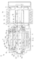
図1には、両回転スクロール型圧縮機1Aが示されている。両回転スクロール型圧縮機1Aは、例えば車両用エンジン等の内燃機関に供給する燃焼用空気(流体)を圧縮する過給機として用いることができる。
Hereinafter, a first embodiment of the present invention will be described with reference to FIG.
FIG. 1 shows a
両回転スクロール型圧縮機1Aは、ハウジング3と、ハウジング3の一端側に収容されたモータ(駆動部)5と、ハウジング3の他端側に収容された駆動側スクロール部材70及び従動側スクロール部材90とを備えている。
The
ハウジング3は、略円筒形状とされており、モータ5を収容するモータ収容部3aと、スクロール部材70,90を収容するスクロール収容部3bとを備えている。
モータ収容部3aの外周には、モータ5を冷却するための冷却フィン3cが設けられている。スクロール収容部3bの端部には、圧縮後の空気を吐出するための吐出口3dが形成されている。なお、図1では示さされていないが、ハウジング3には空気を吸入する空気吸入口が設けられている。
ハウジング3のスクロール収容部3bは、スクロール部材70,90の軸線方向における略中央部に位置する分割面Pにて分割されている。ハウジング3には、後述する図4に示すように、円周方向の所定位置にて外方に突出するフランジ部(締結部)30が設けられている。このフランジ部30に締結手段としてのボルト32を通して固定することによって、分割面Pが締結される。
The
Cooling
The scroll accommodating
モータ5は、図示しない電力供給源から電力が供給されることによって駆動される。モータ5の回転制御は、図示しない制御部からの指令によって行われる。モータ5のステータ5aはハウジング3の内周側に固定されている。モータ5のロータ5bは、駆動回転軸線CL1回りに回転する。ロータ5bには、駆動回転軸線CL1上に延在する駆動軸6が接続されている。駆動軸6は、駆動側スクロール部材70の駆動側駆動軸7cと接続されている。
The
駆動側スクロール部材70は、モータ5側の第1駆動側スクロール部71と、吐出口3d側の第2駆動側スクロール部72とを備えている。
第1駆動側スクロール部71は、第1駆動側端板71aと第1駆動側壁体71bを備えている。
第1駆動側端板71aは、駆動軸6に接続された駆動側軸部7cに接続されており、駆動側回転軸線CL1に対して直交する方向に延在している。駆動側軸部7cは、玉軸受とされた駆動側軸受11を介してハウジング3に対して回動自在に設けられている。
The drive-
The first drive-
The first drive
第1駆動側端板71aは、平面視した場合に略円板形状とされている。第1駆動側端板71a上に、図2に示すように、渦巻状とされた第1駆動側壁体71bが3つ、すなわち3条設けられている。3条とされた第1駆動側壁体71bは、駆動側回転軸線CL1回りに等間隔にて配置されている。第1駆動側壁体71bの巻き終わり部71eは、それぞれ、他の壁部に固定されておらず、独立している。すなわち、各巻き終わり部71e同士を接続して補強するような壁部は設けられていない。
The first drive
図1に示したように、第2駆動側スクロール部72は、第2駆動側端板72aと第2駆動側壁体72bを備えている。第2駆動側壁体72bは、上述した第1駆動側壁体71b(図2参照)と同様に、3条とされている。
第2駆動側端板72aには、駆動側回転軸線CL1方向に延在する第2駆動側軸部72cが接続されている。第2駆動側軸部72cは、玉軸受けとされた第2駆動側軸受14を介して、ハウジング3に対して回転自在に設けられている。第2駆動側軸部72cには、駆動側回転軸線CL1に沿って吐出ポート72dが形成されている。
As shown in FIG. 1, the second drive
A second drive-
第1駆動側スクロール部71と第2駆動側スクロール部72とは、壁体71b,72bの先端(自由端)同士が向かい合った状態で固定されている。第1駆動側スクロール部71と第2駆動側スクロール部72との固定は、半径方向外側に突出するように円周方向において複数箇所設けたフランジ部73に対して締結されたボルト(壁体固定部)31によって行われる。
The first drive side scroll
従動側スクロール部材90は、軸方向(図において水平方向)における略中央に設けられた従動側端板90aを有している。従動側端板90aの中央には貫通孔90hが形成されており、圧縮後の空気が吐出ポート72dへと流れるようになっている。
従動側端板90aの両側には、それぞれ、従動側壁体91b,92bが設けられている。従動側端板90aからモータ5側に設置された第1従動側壁体91bは、第1駆動側スクロール部71の第1駆動側壁体71bと噛み合わされ、従動側端板90aから吐出口3d側に設置された第2従動側壁体92bは、第2駆動側スクロール部72の第2駆動側壁体72bと噛み合わされる。
図3に示すように、第1従動側壁体91bは、3つ、すなわち3条設けられている。3条とされた従動側壁体9bは、従動側回転軸線CL2回りに等間隔にて配置されている。
The driven-
On both sides of the driven
As shown in FIG. 3, the first driven
従動側スクロール部材90の軸方向(図において水平方向)における両端には、第1サポート部材33と第2サポート部材35とが設けられている。第1サポート部材33は、モータ5側に配置され、第2サポート部材35は吐出口3d側に配置されている。第1サポート部材33は、ピンやボルト等の締結部材25aによって第1従動側壁体91bの先端(自由端)に対して固定されており、第2サポート部材35は、ピンやボルト等の締結部材25bによって第2従動側壁体92bの先端(自由端)に対して固定されている。第1サポート部材33の中心軸側には、軸部33aが設けられており、この軸部33aが第1サポート部材用軸受37を介してハウジング3に対して固定されている。第2サポート部材35の中心軸側には、軸部35aが設けられており、この軸部35aが第2サポート部材用軸受38を介してハウジング3に対して固定されている。これにより、各サポート部材33,35を介して、従動側スクロール部材90は、第2中心軸線CL2回りに回転するようになっている。
A
第1サポート部材33と第1駆動側端板71aとの間には、ピンリング機構15が設けられている。すなわち、第1駆動側端板71aにリング部材15aが設けられ、第1サポート部材33にピン部材15bが設けられている。
The
第2サポート部材35と第2駆動側端板72aとの間には、ピンリング機構15が設けられている。すなわち、第2駆動側端板72aにリング部材15aが設けられ、第2サポート部材35にピン部材15bが設けられている。
The
図4には、スクロール部材70,90を回転軸線CL1,CL2方向から見た状態が示されている。同図に示されているように、駆動側回転軸線CL1と従動側回転軸線CL2とは、スクロール部材70,90同士が同一角速度で自転運動する際の旋回半径分だけオフセットされている。これら回転軸線CL1,CL2を結ぶ直線L1よりも側方でかつ両スクロール部材70,90の周囲の領域に、フランジ部30が設けられ、この位置でボルトによってハウジング3の分割面P(図1参照)が締結されている。より具体的には、回転軸線CL1,CL2を通り直線L1に直交する領域に、フランジ部30が設けられている。また、フランジ部30は、両スクロール部材70,90を包囲する外接円C1よりも内側に設けられている。
FIG. 4 shows a state where the
上記構成の両回転スクロール型圧縮機1Cは、以下のように動作する。
モータ5によって駆動軸6が駆動側回転軸線CL1回りに回転させられると、駆動軸6に接続された駆動側軸部7cも回転し、これにより駆動側スクロール部材70が駆動側回転軸線CL1回りに回転する。駆動側スクロール部材70が回転すると、駆動力がピンリング機構15を介して各サポート部材33,35から従動側スクロール部材90へと伝達され、従動側スクロール部材90が従動側回転軸線CL2回りに回転する。このとき、ピンリング機構15のピン部材15bがリング部材15aに対して接触しつつ移動することによって、両スクロール部材70,90が同じ方向に同一角速度で自転運動を行う。
両スクロール部材70,90が自転運動を行うと、ハウジング3の吸入口から吸い込まれた空気が両スクロール部材70,90の外周側から吸入され、両スクロール部材70,90によって形成された圧縮室に取り込まれる。そして、第1駆動側壁体71bと第1従動側壁体91bとによって形成された圧縮室と、第2駆動側壁体72bと第2従動側壁体92bとによって形成された圧縮室とが別々に圧縮される。それぞれの圧縮室は中心側に移動するにしたがって容積が減少し、これに伴い空気が圧縮される。第1駆動側壁体71bと第1従動側壁体91bとによって圧縮された空気は、従動側端板90aに形成された貫通孔90hを通り、第2駆動側壁体72bと第2従動側壁体92bとによって圧縮された空気と合流し、合流後の空気が吐出ポート72dを通り、ハウジング3の吐出口3dから外部へと吐出される。吐出された圧縮空気は、図示しない内燃機関へと導かれ、燃焼用空気として用いられる。
The dual rotary scroll compressor 1C having the above configuration operates as follows.
When the drive shaft 6 is rotated around the drive-side rotation axis CL1 by the
When the two
本実施形態によれば、以下の作用効果を奏する。
両回転スクロール型圧縮機1Aの場合、圧縮室が形成できる距離だけ各スクロール部材70,90の回転軸線CL1,CL2がオフセットされて平行に設けられている。したがって、両スクロール部材70,90を回転軸線から見た場合(図4参照)、両スクロール部材70,90の投影形状は、各回転軸線CL1,CL2を結んだ方向に長軸を有する長円形状となる。したがって、両スクロール部材70,90の回転軸線CL1,CL2を結んだ直線L1から見て側方でかつ両スクロール部材70,90の周囲の領域にスペースが生じることになる。この領域にフランジ部30を設けて分割面Pを締結することとしたので、ハウジング3の外形を可及的に小さくして、両回転スクロール型圧縮機1Aをコンパクトに構成することができる。
また、図4に示したように、フランジ部30は、両スクロール部材70,90を包囲する外接円C1よりも内側に設けられているので、ハウジング3をコンパクトに構成することができる。
なお、本実施形態では、フランジ部30を2つ設けることとしたが、本発明はこれに限定されるものではなく、3つ以上であっても良い。
また、フランジ部30の設置位置は、図4において回転軸線CL1,CL2を通り直線L1に対して直交する領域に設けることとしたが、この領域に限定されるものではなく、この位置から回転軸線CL1,CL2回りに回転させた領域に設けても良い。
According to the present embodiment, the following operation and effect can be obtained.
In the case of the
Further, as shown in FIG. 4, since the
In this embodiment, two
In addition, the installation position of the
[第2実施形態]
次に、本発明の第2実施形態について、図5を用いて説明する。
本実施形態は、第1実施形態の両回転スクロール型圧縮機1Aに対して、取付穴80を設ける位置について説明するものである。したがって、図5には、第1実施形態の両回転スクロール型圧縮1Aと同様の圧縮機が示されており、ハウジング3に形成された取付穴80の位置が追加されている。
取付穴80は、両回転スクロール型圧縮機1Aをエンジン等の外部構造に接続するために用いられる。具体的には、外部構造に取り付けるための取付脚を取り付ける穴として用いられる。
図5に示されているように、駆動側軸受11及び第1サポート部材用軸受37の外周側と、第2駆動側軸14及び第2サポート部材用軸受38の外周側に、取付穴80が形成されている。取付穴80は、貫通孔とされている。
[Second embodiment]
Next, a second embodiment of the present invention will be described with reference to FIG.
In the present embodiment, a position where the mounting
The mounting
As shown in FIG. 5, mounting
このように、本実施形態では、軸受11,14,37,38の外周側は、ハウジング3の外形との間に所定のスペースを確保することができることに着目した。このスペースに、取付穴80を設けることにより、ハウジング3の外形を大きくすることなく取付穴80を形成できるので、両回転スクロール型圧縮機1Aをコンパクトに構成することができる。
As described above, in the present embodiment, attention has been paid to the fact that a predetermined space can be secured between the outer periphery of the
また、図6に示すように、軸受11,14,37,38の外周側に、有底穴としての取付穴80を設けるようにしてもよい。
As shown in FIG. 6, a mounting
なお、上述した各実施形態では、過給機として両回転スクロール型圧縮機を用いることとしたが、本発明はこれに限定されるものではなく、流体を圧縮するものであれば広く利用することができ、例えば空調機械において使用される冷媒圧縮機として用いることもできる。 In each of the above-described embodiments, a double-rotating scroll compressor is used as a supercharger. However, the present invention is not limited to this, and a wide-range compressor that compresses a fluid may be used. For example, it can be used as a refrigerant compressor used in an air conditioning machine.
1A 両回転スクロール型圧縮機
3 ハウジング
3a モータ収容部
3b スクロール収容部
3c 冷却フィン
3d 吐出口
5 モータ(駆動部)
5a ステータ
5b ロータ
6 駆動軸
7c 駆動側軸部
11 駆動側軸受
15 ピンリング機構(同期駆動機構)
15a リング部材
15b ピン部材
25a 締結部材
25b 締結部材
30 フランジ部(締結部)
31 ボルト(壁体固定部)
32 ボルト
33 第1サポート部材
33a 軸部
35 第2サポート部材
35a 軸部
37 第1サポート部材用軸受
38 第2サポート部材用軸受
70 駆動側スクロール部材
71 第1駆動側スクロール部
71a 第1駆動側端板
71b 第1駆動側壁体
72 第2駆動側スクロール部
72a 第2駆動側端板
72b 第2駆動側壁体
72c 第2駆動側軸部
72d 吐出ポート
73 フランジ部
90 従動側スクロール部材
90a 従動側端板
90h 貫通孔
91b 第1従動側壁体
92b 第2従動側壁体
L1 直線
P 分割面
1A
31 bolt (wall fixing part)
32
Claims (3)
従動側端板の中心回りに所定角度間隔を有して設置され、各前記駆動側壁体に対応する数の渦巻状の従動側壁体を有し、これら従動側壁体のそれぞれが対応する前記駆動側壁体に対して噛み合わされることによって圧縮空間を形成する従動側スクロール部材と、
前記駆動側スクロール部材と前記従動側スクロール部材とが同じ方向に同一角速度で自転運動するように前記駆動側スクロール部材から前記従動側スクロール部材に駆動力を伝達する同期駆動機構と、
各前記スクロール部材及び前記同期駆動機構を収容するハウジングと、
を備え、
前記ハウジングは、各前記スクロール部材を含みかつ各前記スクロール部材の各回転軸線に略直交する平面で分割された分割面と、
各前記スクロール部材の各回転軸線を結んだ直線から見て側方でかつ各前記スクロール部材の周囲の領域で、前記分割面を締結する締結部と、を備え、
前記締結部は、前記駆動側スクロール部材及び前記従動側スクロール部材を包囲する外接円よりも内側に設けられていることを特徴とする両回転スクロール型圧縮機。 A drive-side scroll member that is rotationally driven by the drive unit and has a plurality of spiral drive side walls that are installed at predetermined angular intervals around the center of the drive-side end plate,
A plurality of spiral driven side walls are provided around the center of the driven side end plate at a predetermined angular interval and correspond to the respective driving side walls, and each of the driven side walls corresponds to the corresponding driving side wall. A driven scroll member that forms a compression space by being engaged with the body,
A synchronous drive mechanism for transmitting a driving force from the drive scroll member to the driven scroll member so that the drive scroll member and the driven scroll member rotate in the same direction at the same angular velocity,
A housing accommodating each of the scroll members and the synchronous drive mechanism;
With
The housing includes the scroll members, and a divided surface divided by a plane substantially orthogonal to the rotation axis of each of the scroll members,
A fastening portion that fastens the divided surface, in a side view and in a region around each of the scroll members when viewed from a straight line connecting the rotation axes of the scroll members ,
The double-rotating scroll compressor according to claim 1, wherein the fastening part is provided inside a circumscribed circle surrounding the driving scroll member and the driven scroll member .
前記従動側スクロール部材の回転を支持する従動側軸受と、
を備え、
前記駆動側軸受及び/又は前記従動側軸受の外周側に、外部構造に取り付けるための取付穴が形成されていることを特徴とする請求項1又は2に記載の両回転スクロール型圧縮機。 A drive-side bearing that supports rotation of the drive-side scroll member;
A driven-side bearing that supports rotation of the driven-side scroll member;
With
The dual rotary scroll compressor according to claim 1 or 2 , wherein a mounting hole for mounting to an external structure is formed on an outer peripheral side of the driving side bearing and / or the driven side bearing.
Priority Applications (5)
| Application Number | Priority Date | Filing Date | Title |
|---|---|---|---|
| JP2016151544A JP6665055B2 (en) | 2016-08-01 | 2016-08-01 | Double rotary scroll compressor |
| PCT/JP2017/027939 WO2018025877A1 (en) | 2016-08-01 | 2017-08-01 | Double rotating scroll-type compressor |
| CN201780047356.2A CN109729720B (en) | 2016-08-01 | 2017-08-01 | Double-rotation scroll compressor |
| US16/321,661 US20200378383A1 (en) | 2016-08-01 | 2017-08-01 | Co-rotating scroll compressor |
| EP17836980.7A EP3480464B1 (en) | 2016-08-01 | 2017-08-01 | Double rotating scroll-type compressor |
Applications Claiming Priority (1)
| Application Number | Priority Date | Filing Date | Title |
|---|---|---|---|
| JP2016151544A JP6665055B2 (en) | 2016-08-01 | 2016-08-01 | Double rotary scroll compressor |
Publications (3)
| Publication Number | Publication Date |
|---|---|
| JP2018021464A JP2018021464A (en) | 2018-02-08 |
| JP2018021464A5 JP2018021464A5 (en) | 2019-04-04 |
| JP6665055B2 true JP6665055B2 (en) | 2020-03-13 |
Family
ID=61073490
Family Applications (1)
| Application Number | Title | Priority Date | Filing Date |
|---|---|---|---|
| JP2016151544A Active JP6665055B2 (en) | 2016-08-01 | 2016-08-01 | Double rotary scroll compressor |
Country Status (5)
| Country | Link |
|---|---|
| US (1) | US20200378383A1 (en) |
| EP (1) | EP3480464B1 (en) |
| JP (1) | JP6665055B2 (en) |
| CN (1) | CN109729720B (en) |
| WO (1) | WO2018025877A1 (en) |
Families Citing this family (2)
| Publication number | Priority date | Publication date | Assignee | Title |
|---|---|---|---|---|
| JP6698726B2 (en) | 2018-03-12 | 2020-05-27 | 三菱重工業株式会社 | Double rotary scroll compressor |
| JP7017256B2 (en) * | 2019-12-17 | 2022-02-08 | 有限会社スクロール技研 | Scroll type fluid machine |
Family Cites Families (10)
| Publication number | Priority date | Publication date | Assignee | Title |
|---|---|---|---|---|
| JPS62210276A (en) * | 1986-03-07 | 1987-09-16 | Mitsubishi Electric Corp | Scroll compressor |
| JPH02227575A (en) * | 1989-02-28 | 1990-09-10 | Diesel Kiki Co Ltd | Fluid machine with scroll |
| JP2925674B2 (en) * | 1990-07-16 | 1999-07-28 | 三洋電機株式会社 | Scroll compressor |
| JPH10159756A (en) * | 1996-11-29 | 1998-06-16 | Kimie Nakamura | Scroll fluid machine |
| US5938419A (en) * | 1997-01-17 | 1999-08-17 | Anest Iwata Corporation | Scroll fluid apparatus having an intermediate seal member with a compressed fluid passage therein |
| JP3473448B2 (en) * | 1998-10-05 | 2003-12-02 | 松下電器産業株式会社 | Compressor and method of assembling the same |
| JP5812693B2 (en) * | 2011-05-09 | 2015-11-17 | アネスト岩田株式会社 | Scroll type fluid machine |
| JP5925578B2 (en) * | 2012-04-25 | 2016-05-25 | アネスト岩田株式会社 | Scroll expander |
| JP5931563B2 (en) * | 2012-04-25 | 2016-06-08 | アネスト岩田株式会社 | Scroll expander |
| JP5931564B2 (en) * | 2012-04-25 | 2016-06-08 | アネスト岩田株式会社 | Double-rotating scroll expander and power generation device including the expander |
-
2016
- 2016-08-01 JP JP2016151544A patent/JP6665055B2/en active Active
-
2017
- 2017-08-01 WO PCT/JP2017/027939 patent/WO2018025877A1/en unknown
- 2017-08-01 EP EP17836980.7A patent/EP3480464B1/en active Active
- 2017-08-01 CN CN201780047356.2A patent/CN109729720B/en not_active Expired - Fee Related
- 2017-08-01 US US16/321,661 patent/US20200378383A1/en not_active Abandoned
Also Published As
| Publication number | Publication date |
|---|---|
| EP3480464B1 (en) | 2020-09-30 |
| EP3480464A1 (en) | 2019-05-08 |
| WO2018025877A1 (en) | 2018-02-08 |
| CN109729720B (en) | 2020-12-29 |
| JP2018021464A (en) | 2018-02-08 |
| US20200378383A1 (en) | 2020-12-03 |
| EP3480464A4 (en) | 2019-05-08 |
| CN109729720A (en) | 2019-05-07 |
Similar Documents
| Publication | Publication Date | Title |
|---|---|---|
| CN110121596B (en) | Double-rotation scroll compressor | |
| EP3489514B1 (en) | Bidirectional-rotation-type scroll compressor | |
| WO2019150680A1 (en) | Double rotating scroll-type compressor and assembly method therefor | |
| CN109563833B (en) | Double-rotation scroll compressor and design method thereof | |
| CN110337543B (en) | Double-rotation scroll compressor | |
| JP6665055B2 (en) | Double rotary scroll compressor | |
| JP6727978B2 (en) | Double rotary scroll compressor | |
| WO2018139538A1 (en) | Twin rotary scroll compressor and assembly method thereof | |
| JP6707478B2 (en) | Double rotary scroll compressor | |
| JP6698726B2 (en) | Double rotary scroll compressor | |
| WO2023188916A1 (en) | Double rotary-type scroll compressor | |
| WO2018151015A1 (en) | Two-way-rotating scroll compressor | |
| JP2018059462A (en) | Double rotation scroll-type compressor | |
| WO2019171448A1 (en) | Double-rotating scroll compressor | |
| JP2019065780A (en) | Both-rotation scroll-type fluid machine | |
| JP2009041387A (en) | Electric compressor |
Legal Events
| Date | Code | Title | Description |
|---|---|---|---|
| A711 | Notification of change in applicant |
Free format text: JAPANESE INTERMEDIATE CODE: A712 Effective date: 20180613 |
|
| A521 | Request for written amendment filed |
Free format text: JAPANESE INTERMEDIATE CODE: A523 Effective date: 20190221 |
|
| A621 | Written request for application examination |
Free format text: JAPANESE INTERMEDIATE CODE: A621 Effective date: 20190221 |
|
| A711 | Notification of change in applicant |
Free format text: JAPANESE INTERMEDIATE CODE: A711 Effective date: 20190614 |
|
| TRDD | Decision of grant or rejection written | ||
| A01 | Written decision to grant a patent or to grant a registration (utility model) |
Free format text: JAPANESE INTERMEDIATE CODE: A01 Effective date: 20200121 |
|
| A61 | First payment of annual fees (during grant procedure) |
Free format text: JAPANESE INTERMEDIATE CODE: A61 Effective date: 20200219 |
|
| R150 | Certificate of patent or registration of utility model |
Ref document number: 6665055 Country of ref document: JP Free format text: JAPANESE INTERMEDIATE CODE: R150 |