JP6665013B2 - Bottom structure of twin skeg ship and twin skeg ship - Google Patents
Bottom structure of twin skeg ship and twin skeg ship Download PDFInfo
- Publication number
- JP6665013B2 JP6665013B2 JP2016071336A JP2016071336A JP6665013B2 JP 6665013 B2 JP6665013 B2 JP 6665013B2 JP 2016071336 A JP2016071336 A JP 2016071336A JP 2016071336 A JP2016071336 A JP 2016071336A JP 6665013 B2 JP6665013 B2 JP 6665013B2
- Authority
- JP
- Japan
- Prior art keywords
- propeller
- pair
- ship
- width direction
- skegs
- Prior art date
- Legal status (The legal status is an assumption and is not a legal conclusion. Google has not performed a legal analysis and makes no representation as to the accuracy of the status listed.)
- Active
Links
Images


Classifications
-
- B—PERFORMING OPERATIONS; TRANSPORTING
- B63—SHIPS OR OTHER WATERBORNE VESSELS; RELATED EQUIPMENT
- B63B—SHIPS OR OTHER WATERBORNE VESSELS; EQUIPMENT FOR SHIPPING
- B63B1/00—Hydrodynamic or hydrostatic features of hulls or of hydrofoils
- B63B1/02—Hydrodynamic or hydrostatic features of hulls or of hydrofoils deriving lift mainly from water displacement
- B63B1/04—Hydrodynamic or hydrostatic features of hulls or of hydrofoils deriving lift mainly from water displacement with single hull
- B63B1/08—Shape of aft part
-
- B—PERFORMING OPERATIONS; TRANSPORTING
- B63—SHIPS OR OTHER WATERBORNE VESSELS; RELATED EQUIPMENT
- B63B—SHIPS OR OTHER WATERBORNE VESSELS; EQUIPMENT FOR SHIPPING
- B63B1/00—Hydrodynamic or hydrostatic features of hulls or of hydrofoils
- B63B1/32—Other means for varying the inherent hydrodynamic characteristics of hulls
- B63B1/34—Other means for varying the inherent hydrodynamic characteristics of hulls by reducing surface friction
- B63B1/38—Other means for varying the inherent hydrodynamic characteristics of hulls by reducing surface friction using air bubbles or air layers gas filled volumes
-
- Y—GENERAL TAGGING OF NEW TECHNOLOGICAL DEVELOPMENTS; GENERAL TAGGING OF CROSS-SECTIONAL TECHNOLOGIES SPANNING OVER SEVERAL SECTIONS OF THE IPC; TECHNICAL SUBJECTS COVERED BY FORMER USPC CROSS-REFERENCE ART COLLECTIONS [XRACs] AND DIGESTS
- Y02—TECHNOLOGIES OR APPLICATIONS FOR MITIGATION OR ADAPTATION AGAINST CLIMATE CHANGE
- Y02T—CLIMATE CHANGE MITIGATION TECHNOLOGIES RELATED TO TRANSPORTATION
- Y02T70/00—Maritime or waterways transport
- Y02T70/10—Measures concerning design or construction of watercraft hulls
Description
本発明は、船底の船尾側に船体幅方向に間隔をあけて設けられた一対のスケグと、スケグの船尾側に個別に設置されたプロペラとを備えた、ツインスケグ船の船底構造及びツインスケグ船に関する。 The present invention relates to a bottom structure of a twin-skeg ship and a twin-skeg ship, comprising: a pair of skegs provided on a stern side of a ship hull at intervals in a hull width direction; and a propeller separately installed on a stern side of the skeg. .
船底の船尾側(後ろ側)に、下方に向けて突出したスケグを船体幅方向に間隔をあけて左右一対に設け、これらのスケグの後ろ側にプロペラを配置したツインスケグ船が知られている。ツインスケグ船では、スケグの相互間に、船尾側に向かって上方に傾斜する傾斜面(以下「船尾傾斜面」とよぶ)を船底に設け、この船尾傾斜面と両スケグとの相互間に、トンネル状の船底凹部が形成されている。
船底凹部を形成することで、航行時、船尾傾斜面に沿って後方のプロペラに向かって上昇する水の上昇流が得られる。両プロペラは内回り、つまり、両プロペラの相互間の上昇流に対向して下向きに回転するので、これによって推進効率を向上することができる。
There is known a twin skeg ship in which a pair of left and right skegs protruding downward are provided at the stern side (rear side) of the bottom of the hull at intervals in the hull width direction, and a propeller is arranged behind these skegs. In twin-skeg ships, an inclined surface (hereinafter referred to as “stern inclined surface”) that slopes upward toward the stern is provided at the bottom between the skegs, and a tunnel is provided between the stern inclined surface and the two skegs. A hull bottom recess is formed.
By forming the bottom recess, a rising flow of water that rises toward the rear propeller along the stern inclined surface during navigation can be obtained. Both propellers rotate inward, that is, rotate downwardly in opposition to the upward flow between the two propellers, so that propulsion efficiency can be improved.
また、推進効率を向上する技術として、船首側から船尾側に向かう気泡流を発生させて、船底を気泡流で覆うことにより船体摩擦抵抗を低減する空気潤滑システムが知られている。空気潤滑システムを使用して船体摩擦抵抗(推進抵抗)を低減することにより、推進効率を向上することができる。
ツインスケグ船においても、空気潤滑システムを装備したものが種々開発されている(例えば特許文献1)。
As a technique for improving propulsion efficiency, there is known an air lubrication system that generates a bubble flow from the bow side to the stern side and reduces the frictional resistance of the hull by covering the bottom with the bubble flow. By using an air lubrication system to reduce hull friction resistance (propulsion resistance), propulsion efficiency can be improved.
Various twin-skeg ships equipped with an air lubrication system have been developed (for example, Patent Document 1).
ツインスケグ船では、上述したように左右のスケグの相互間に船尾傾斜面を設けてプロペラに向かう水の上昇流を形成することで推進効率を向上させているが、より一層の推進効率の向上が要望されている。
また、ツインスケグ船において空気潤滑システムを装備した場合、プロペラ相互間の船底凹部により、気泡が水流と共にプロペラ相互間へと案内され、且つ、その形状(トンネル状の凹部)により気泡流の逃げ道がなくなる(つまり気泡流がプロペラ外方に反れて流れることが規制される)ため、気泡流がプロペラに流入しやすい。気泡流がプロペラに流入すると、キャビテーションが増加して、それに伴うリスク(プロペラのエロージョン、変動圧増加による船体の振動や騒音)が高くなるおそれがある。
The twin skeg ship improves the propulsion efficiency by providing a stern inclined surface between the left and right skegs to form an upward flow of water toward the propeller, as described above. Requested.
Also, when the twin-skeg ship is equipped with an air lubrication system, air bubbles are guided between the propellers together with the water flow by the bottom recess between the propellers, and the shape (tunnel-shaped recess) eliminates the escape of the bubble flow. (That is, it is regulated that the bubble flow is warped to the outside of the propeller.) Therefore, the bubble flow easily flows into the propeller. When the bubble stream flows into the propeller, cavitation increases, which may increase risks (such as erosion of the propeller and vibration and noise of the hull due to an increase in the fluctuating pressure).
本発明は、推進効率を向上できるようにした、ツインスケグ船の船底構造及びツインスケグ船を提供することを目的とする。
また、本発明は、空気潤滑システムにより船底に噴出された気泡が、プロペラへ流入することを抑制できるようにした、ツインスケグ船の船底構造及びツインスケグ船を提供することを目的とする。
An object of the present invention is to provide a twin-skeg ship bottom structure and a twin-skeg ship capable of improving propulsion efficiency.
It is another object of the present invention to provide a twin-skeg ship bottom structure and a twin-skeg ship capable of suppressing air bubbles jetted to the ship bottom by an air lubrication system from flowing into a propeller.
(1)上記の目的を達成するために、本発明のツインスケグ船の船底構造は、船底の船尾側に船体幅方向に間隔をあけて設けられた一対のスケグと、前記一対のスケグの船尾側に個別に設置され、互いに内回りに回転するプロペラと、前記一対のスケグの相互間において前記船底に形成され、前記船尾側に向かって上方傾斜する傾斜面とを備えた、ツインスケグ船の船底構造であって、前記傾斜面の横断面は、第1位置では、前記船体幅方向に沿った平坦形状に形成され、前記第1位置よりも前記船尾側の第2位置では、前記船体幅方向に間隔をあけて設けられ上方に凹んだ一対の凹状部と、前記一対の凹状部の相互間に設けられ下方に凸となる凸状部とを有する起伏形状に形成され、前記凸状部は、湾曲状凸状部であり、前記第2位置は、前記プロペラから前記プロペラの直径の0.5倍だけ前方の位置と、前記プロペラから前記プロペラの直径の1.5倍だけ前方の位置との間において設定され、前記プロペラと前記第2位置との間の範囲において、下式[1]により規定される抉り深さの最大値が、計画吃水の4%以上且つ6%以下であることを特徴としている。
抉り深さ=(前記凹状部の上端の高さ)−(前記凸状部の下端の高さ)…[1]
(1) In order to achieve the above object, a twin-skeg ship bottom structure of the present invention includes a pair of skegs provided on the stern side of the stern at intervals in the hull width direction, and a stern side of the pair of skegs. A twin-skeg ship hull structure, comprising: a propeller that is individually installed at each other and rotates inwardly with each other; and a slope formed on the ship bottom between the pair of skegs and inclined upward toward the stern side. The cross section of the inclined surface is formed in a flat shape along the hull width direction at a first position, and is spaced apart in the hull width direction at a second position closer to the stern side than the first position. A pair of concave portions that are provided with a gap and that are concave upward, and a convex portion that is provided between the pair of concave portions and that is convex downward and is formed in an undulating shape, and the convex portion has a curved shape. And the second position is The propeller is set between a position in front of the propeller by 0.5 times the diameter of the propeller and a position in front of the propeller by 1.5 times the diameter of the propeller, and is located between the propeller and the second position. In the range between, the maximum value of the gouging depth defined by the following equation [1] is characterized in that the draft is 4% or more and 6% or less .
Gouge depth = (height of the upper end of the concave portion)-(height of the lower end of the convex portion) ... [1]
(2)本発明のもう一つのツインスケグ船の船底構造は、船底の船尾側に船体幅方向に間隔をあけて設けられた一対のスケグと、前記一対のスケグの船尾側に個別に設置され、互いに内回りに回転するプロペラと、前記一対のスケグの相互間において前記船底に形成され、前記船尾側に向かって上方傾斜する傾斜面とを備えた、ツインスケグ船の船底構造であって、前記傾斜面の横断面は、第1位置では、前記船体幅方向に沿った平坦形状に形成され、前記第1位置よりも前記船尾側の第2位置では、前記船体幅方向に間隔をあけて設けられ上方に凹んだ一対の凹状部と、前記一対の凹状部の相互間に設けられ下方に凸となる凸状部とを有する起伏形状に形成され、前記凸状部は、前記船体幅方向で中央に平坦面を備えたステップ状凸状部であり、前記第2位置は、前記プロペラから前記プロペラの直径の0.5倍だけ前方の位置と、前記プロペラから前記プロペラの直径の1.5倍だけ前方の位置との間において設定され、前記プロペラと前記第2位置との間の範囲において、下式[2]により規定される抉り深さの最大値が、計画吃水の4%以上且つ6%以下であることを特徴としている。
抉り深さ=(前記凹状部の上端の高さ)−(前記平坦面の高さ)…[2]
( 2 ) Another twin-skeg ship hull bottom structure of the present invention is a pair of skegs provided on the stern side of the stern at intervals in the hull width direction, and separately installed on the stern side of the pair of skegs, A bottom structure of a twin skeg ship, comprising: a propeller rotating inwardly to each other; and an inclined surface formed on the bottom of the ship between the pair of skegs and inclined upward toward the stern side. Is formed in a flat shape along the hull width direction at a first position, and is provided at a second position closer to the stern side than the first position at an interval in the hull width direction and provided at A pair of concave portions that are recessed into, and are formed in an undulating shape having a downwardly convex portion provided between the pair of concave portions, and the convex portion is located at the center in the hull width direction. Step-shaped convex part with flat surface There, the second position is a position of the front by 0.5 times the diameter of the propeller from the propeller is set at between the propeller and the position of the front only 1.5 times the diameter of the propeller, the In the range between the propeller and the second position, the maximum value of the gouging depth defined by the following equation [2] is not less than 4% and not more than 6% of the planned draft .
Gouge depth = (height of the upper end of the concave portion)-(height of the flat surface) ... [2]
(3)上記の目的を達成するために、本発明のさらにもう一つのツインスケグ船の船底構造は、船底の船尾側に船体幅方向に間隔をあけて設けられた一対のスケグと、前記一対のスケグの船尾側に個別に設置され、互いに内回りに回転するプロペラと、前記一対のスケグの相互間において前記船底に形成され、前記船尾側に向かって上方傾斜する傾斜面とを備えた、ツインスケグ船の船底構造であって、前記傾斜面は、第1位置では、前記船体幅方向に沿った平坦形状に形成され、前記第1位置よりも前記船尾側の第2位置では、前記プロペラよりも前記船体幅方向のセンターライン側に上端が配置されると共に上方に凹んだ単一の凹状部を有する凹形状に形成され、前記第2位置は、前記プロペラから前記プロペラの直径の0.5倍だけ前方の位置と、前記プロペラから前記プロペラの直径の1.5倍だけ前方の位置との間において設定され、前記プロペラと前記第2位置との間の範囲において、下式[3]により規定される抉り深さの最大値が、計画吃水の4%以上且つ6%以下であることを特徴としている。
抉り深さ=(前記凹状部の上端の高さ)−(前記横断面における、前記プロペラの回転中心よりもプロペラ半径だけ前記内側の位置における高さ)…[3]
( 3 ) In order to achieve the above object, still another twin-skeg ship bottom structure of the present invention includes a pair of skegs provided on the stern side of the bottom at intervals in the hull width direction; A twin skeg ship comprising: a propeller which is individually installed on the stern side of the skeg and rotates inwardly to each other; and a slope formed on the bottom of the stern between the pair of skegs and inclined upward toward the stern side. The inclined surface is formed in a flat shape along the hull width direction at a first position, and at a second position closer to the stern side than the first position, the inclined surface is more than the propeller. The upper end is disposed on the center line side in the hull width direction and is formed in a concave shape having a single concave portion that is concave upward, and the second position is 0.5 times the diameter of the propeller from the propeller. And a position in front of the propeller by 1.5 times the diameter of the propeller from the propeller, and is defined by the following equation [3] in a range between the propeller and the second position. It is characterized in that the maximum value of the gouging depth is not less than 4% and not more than 6% of the planned draft.
Gouge depth = (height of the upper end of the concave portion)-(height of the cross section at the position inside the propeller radius from the center of rotation of the propeller) [3]
(4)上記の目的を達成するために、本発明のツインスケグ船は(1)〜(3)の何れかに記載の船底構造を備えたことを特徴としている。 ( 4 ) In order to achieve the above object, a twin skeg ship of the present invention is provided with the bottom structure according to any one of (1) to ( 3 ).
(5)前記船底に気泡を噴出する空気潤滑システムを備えることが好ましい。 ( 5 ) It is preferable to provide an air lubrication system for ejecting air bubbles to the bottom of the ship.
本発明によれば、一対のスケグの相互間において船尾側に向かって上方傾斜する傾斜面が船底に形成され、この傾斜面の横断面は、第1位置では、船体幅方向に沿った平坦形状に形成され、第1位置よりも船尾側の第2位置では、船体幅方向に間隔をあけて設けられ上方に凹んだ一対の凹状部と、これらの一対の凹状部の相互間に設けられ下方に凸となる凸状部とを有する起伏形状に形成されている。
これにより、傾斜面の後方に向かう上方傾斜が、スケグのそれぞれの内方に設けられた凹状部がある分だけ急傾斜となるので、傾斜面に沿ってプロペラへ流れる上昇流の上向き成分が大きくなり、上昇流に対し下向きに回転するするプロペラにより高い推進力が得られ、推進効率を向上することができる。
さらに、凹状部の相互間には、凸状部が設けられているので、凸状部が存在する分だけ、スケグと傾斜面との間に形成される上昇流の流路断面積が小さくなって、その分だけ、凹状部の上昇流の速度が速くなり、この点でも推進効率を向上することができる。
According to the present invention, an inclined surface inclined upward toward the stern between the pair of skegs is formed on the bottom of the ship, and the cross section of the inclined surface has a flat shape along the hull width direction at the first position. At a second position closer to the stern side than the first position, a pair of concave portions provided at intervals in the hull width direction and depressed upward, and a pair of concave portions provided between the pair of concave portions, And a convex portion having a convex shape.
As a result, the upward inclination toward the rear of the inclined surface becomes steep as much as the concave portion provided inside each of the skegs, so that the upward component of the upward flow flowing to the propeller along the inclined surface is large. Therefore, a high propulsion force can be obtained by the propeller rotating downward with respect to the upward flow, and the propulsion efficiency can be improved.
Further, since the convex portions are provided between the concave portions, the cross-sectional area of the upward flow formed between the skeg and the inclined surface is reduced by the existence of the convex portions. As a result, the speed of the upward flow in the concave portion increases correspondingly, and the propulsion efficiency can be improved also in this regard.
さらに、空気潤滑システムを装備した場合には、船底に噴出された気泡が、凹状部に集まって流れるようになるので、気泡は、プロペラの外を通過して船尾側へと流れるようになり、気泡がプロペラへ流入することを抑制できる Furthermore, when the air lubrication system is equipped, the air bubbles ejected to the bottom of the hull gather and flow in the concave portion, so that the air bubbles pass outside the propeller and flow to the stern side, Bubbles can be prevented from flowing into the propeller
以下、図面を参照して、本発明の各実施の形態について説明する。なお、以下に示す各実施形態はあくまでも例示に過ぎず、以下の各実施形態で明示しない種々の変形や技術の適用を排除する意図はない。以下の各実施形態の構成は、それらの趣旨を逸脱しない範囲で種々変形して実施することができる。
なお、以下の説明では、船舶1の船首11側(進行方向)を前方とし、船尾12側を後方とし、前方を基準に左右を定め、重力の方向を下方とし、その逆を上方として説明する。また、船体前後方向(以下「前後方向」ともいう)Xと直交する水平方向を船体幅方向(以下「幅方向」又は「船幅方向」ともいう)Yとし、船幅方向YのセンターラインCLに近づく側を内側とし、その逆にセンターラインCLから離れる側を外側として説明する。
Hereinafter, embodiments of the present invention will be described with reference to the drawings. Note that each embodiment described below is merely an example, and there is no intention to exclude various modifications and application of technology that are not explicitly described in the following embodiments. The configurations of the following embodiments can be variously modified and implemented without departing from the spirit thereof.
In the following description, the bow 11 side (traveling direction) of the ship 1 is defined as the front, the
[1.第1実施形態]
[1−1.船舶の全体構成]
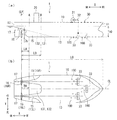
本発明の第1実施形態としての船舶の全体構成について、図1(a),(b)を参照して説明する。
船舶1は、図1(a),(b)に示すように、船舶1の本体である船体10と、船舶1の各種制御が行われるコントロールルーム20と、空気潤滑システム30とを備える。
船舶1は、ツインスケグ船であり、船底13の後部側には、下方に突出したスケグ15が、幅方向Yに間隔をあけて、センターラインCLの左右両側に一対に設けられると共に、各スケグ15の後部に、互いに内回りするプロペラ16がそれぞれ取り付けられている。また、各プロペラ16の後方には、船体10の進行方向を定める舵17がそれぞれ設置されている。なお、プロペラ16の内回りとは、プロペラ16の上部において内側(センターラインCL側)へ回転することである。
以下、左右のスケグ15を区別する場合には、左側のスケグ15をスケグ15Lと表記し、右側のスケグ15をスケグ15Rと表記する。同様に左右のプロペラ16を区別する場合には、左側のプロペラ16をプロペラ16Lと表記し、右側のプロペラ16をプロペラ16Rと表記する。
なお、スケグ15L,15Rの形状及び配置、並びに、プロペラ16L,16Rの配置など、船体10の基本的な構造はセンターラインCLに対して対称である。
[1. First Embodiment]
[1-1. Overall structure of ship]
An overall configuration of a ship as a first embodiment of the present invention will be described with reference to FIGS. 1 (a) and 1 (b).
As shown in FIGS. 1A and 1B, the marine vessel 1 includes a
The ship 1 is a twin skeg ship, and a pair of
Hereinafter, when the left and
The basic structure of the
空気潤滑システム30は、船底13から空気を噴出して船底13と水面との境界に気泡100の流れを発生させ、この気泡流100により船底13を覆う気泡層を形成することで航行する船体10の摩擦抵抗を低減するものである〔図1(a),(b)では気泡100を一部のみ示す〕。
具体的には、空気潤滑システム30は、例えばブロアやコンプレッサにより構成される空気供給源31と、船底13の船首11寄りに設置された複数の気泡噴出部33と、空気供給源31と各気泡噴出部33とを繋ぐ空気供給通路32とを備えて構成され、空気供給源31を作動させることで、各気泡噴出部33から船尾12に向けて気泡100が噴出される。
The
More specifically, the
また、船底13のスケグ15L,15Rの相互間に、前後方向Xの中央から後方に向かって上方に傾斜する傾斜面(以下「船尾傾斜面」とも呼ぶ)131が設けられており、船尾傾斜面131とスケグ間15L,15Rとの相互間に、トンネル状の凹所132が形成されている。
Further, between the
[1−2.船底構造]
船底13の船尾傾斜面131に関して、図1(a),(b)に加え図2(a),(b)を参照してさらに説明する。
図1(a),(b)に示す位置(第2位置)A及び位置(第1位置)Bは、後述するように船尾傾斜面131の形状を規定するための位置である。
位置Aは、位置Bよりも後方の位置であって、プロペラ16の前後方向Xに関する位置(以下「プロペラ位置」と呼ぶ)Pよりも所定距離LAだけ前方の位置として定義され、位置Bはプロペラ位置Pよりも所定距離LBだけ前方の位置として定義される。
ここで、プロペラ位置Pとはプロペラ16の前後方向の中心LPの位置をいう。また、所定距離LAは、プロペラ16の直径Dpの0.5倍〜1.5倍の範囲で設定される(Dp×0.5≦LA≦Dp×1.5)。所定距離LBは、これに限定されるものではないが例えば船長L0の10%として設定される(LB=L0×0.1)。なお、図1では便宜的に所定距離LBを長めに示している。
[1-2. Ship bottom structure]
The stern
The position (second position) A and the position (first position) B shown in FIGS. 1A and 1B are positions for defining the shape of the stern
The position A is a position behind the position B, and is defined as a position ahead of a position P (hereinafter referred to as a “propeller position”) P in the front-rear direction X of the
Here, the propeller position P refers to the position of the center LP of the
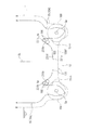
図2は位置A,Bにおける横断面形状(前後方向Xに対して垂直に切断した断面形状)を示す模式図であり、位置Aにおける横断面形状を実線で示し、位置Bにおける横断面形状を破線で示す。なお、符号16Xは、プロペラ16が回転時に描くプロペラ面である。
船底13の船尾傾斜面131は、図2に示すように、位置Bでは平坦な形状をしており、センターラインCLを含む中央部が平坦部131fとして形成されている。平坦部131fは、例えばセンターラインCLを中心にプロペラ直径Dpと同じ長さの幅寸法Wfを有している(Wf=Dp)。
FIG. 2 is a schematic diagram showing a cross-sectional shape at positions A and B (a cross-sectional shape cut perpendicularly to the front-rear direction X). The cross-sectional shape at position A is shown by a solid line, and the cross-sectional shape at position B is shown. Shown by broken lines.
As shown in FIG. 2, the stern
これに対し、位置Aでは、位置Bよりも鉛直上方において、センターラインCLを含む中央部が下方に凸となる凸状部131aを有しており、凸状部131aを有することで、凸状部131aとスケグ15Lとの間、及び、凸状部131aとスケグ15Rとの間にそれぞれ窪み部(凹状部)131bが形成されている。換言すれば、位置Aでは、船尾傾斜面131は、各スケグ15の内側にそれぞれ窪み部131bが形成され、窪み部131b,131bの相互間に凸状部131aが形成された起伏形状とされている。
本実施形態では、凸状部131aは、センターラインCLに下端131a_btmを有する湾曲形状の凸状部であり、各窪み部131bは、スケグ15の内壁面15inに連設され、スケグ15の内側の付け根部に設けられた湾曲形状の凹状部である。
On the other hand, at the position A, the central portion including the center line CL has a
In the present embodiment, the
なお、本実施形態では、船尾傾斜面131の横断面形状は、前後方向Xに沿って連側的に変化し、B位置の横断面形状から後方になるにしたがってA位置の横断面形状へと徐々に変化する。また、本実施形態では、A位置からプロペラ面Pにかけての船尾傾斜面131の横断面形状は、A位置の横断面形状と同様に、窪み部の相互間に凸状部が形成された起伏形状とされている。
In the present embodiment, the cross-sectional shape of the stern
そして、プロペラ位置Pと位置Aとの間の範囲RA(図1(b)参照)において、下式(1)により求めた横断面形状の抉り深さΔh1の最大値が、計画吃水h0(図1(a)参照)の4%以上且つ6%以下になるように設定される。
下式(1)中のh1aは、横断面形状における凸状部131aの下端131a_btmの高さ(換言すれば横断面形状におけるセンターラインCL上の船底13の高さ)である。下式(1)中のh1bは、横断面形状における窪み部131bの上端131b_tpの高さ(換言すれば、横断面形状における船底13の最大高さ)である。
Δh1=h1b−h1a・・・(1)
なお、計画吃水h0とは、計画上の吃水であり、実航行時に想定される代表的な積載重量時の喫水をいう。
また、図2では、凸状部131aの下端131a_btmの高さh1a及び窪み部131bの上端131b_tpの高さh1bを、プロペラ16の回転中心Cpの高さを基準として示している。
Then, in a range RA between the propeller position P and the position A (see FIG. 1B), the maximum value of the gouge depth Δh1 of the cross-sectional shape obtained by the following equation (1) is the planned draft h0 (FIG. 1 (a)) to 4% or more and 6% or less.
H1a in the following equation (1) is the height of the lower end 131a_btm of the
Δh1 = h1b−h1a (1)
Note that the planned draft h0 is a draft according to a plan, and refers to a draft at the time of a typical loaded weight assumed during actual navigation.
Further, in FIG. 2, the height h1a of the lower end 131a_btm of the
[1−3.作用・効果]
本発明の第1実施形態によれば、図1及び図2に示すように、船尾傾斜面131を、位置Bでは平坦な形状とし、位置Bよりも後方の位置Aでは、プロペラ16が取り付けられたスケグ15の直ぐ内側に窪み部131bをそれぞれ形成した。これにより、船尾傾斜面131の後方に向かう上方傾斜が、窪み部131bの深さ(抉り深さ)Δh1分だけ急傾斜となる。これにより、船尾傾斜面131に沿って位置Bから位置Aに向かって(つまり後方に向かって)プロペラ16へ流れる上昇流Fupを、窪み部131bを設けない場合よりも強い上昇流とすることができる。
したがって、矢印AL,ARで示すように上昇流Fupに対して対向回転するプロペラ16L,16Rにより、窪み部131bを設けない場合よりも高い推進力が得られ、推進効率を向上することができる。
さらに、凸状部131aが設けられているので、凸状部131aが存在する分だけ、スケグ15の相互間の横断面積、すなわち上昇流Fupの流路断面積が少なくなって、その分だけ、上昇流Fupを強くすることができ、この点でも推進効率を向上することができる。
[1-3. Action / Effect]
According to the first embodiment of the present invention, as shown in FIGS. 1 and 2, the stern
Therefore, as shown by the arrows AL and AR, the
Furthermore, since the
特に、範囲RA(図1(b)参照)における横断面の抉り深さΔh1の最大値を計画吃水h0の4%以上且つ6%以下に設定しているので、推進効率を最適化することができる。つまり、抉り深さΔh1が計画吃水h0の4%未満では、船尾傾斜面131の上昇角度を十分に増加することができず、推進効率を向上できるほど強い上昇流が得られない。また、抉り深さΔh1が6%を越えると、船底13が下方に過剰に膨らんだ形状となって船底13の浸水面積が増加して、却って、航行時の船体10の抵抗が増大してしまう。
In particular, since the maximum value of the gouge depth Δh1 of the cross section in the range RA (see FIG. 1B) is set to 4% or more and 6% or less of the planned draft h0, the propulsion efficiency can be optimized. it can. In other words, if the goug depth Δh1 is less than 4% of the planned draft h0, the ascending angle of the
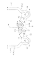
また、図3に示すように、空気潤滑システム30の気泡噴出部33(図1参照)から噴出された気泡100は、船尾傾斜面131とスケグ間15L,15Rとの相互間に形成されたトンネル状の凹所132内を流れるようになるが、この気泡100は、プロペラ面16Xよりも上方に形成される窪み部131bに集まって流れるようになるので、気泡100は、プロペラ16の内側斜め上方を通過して船尾側12へと流れるようになる。
したがって、気泡100がプロペラ16へ流入することを抑制できる。
As shown in FIG. 3, the
Therefore, it is possible to suppress the
[2.第2実施形態]
[2−1.構成]
本発明の第2実施形態の船舶について、図4及び図5を参照して説明する。なお、第1実施形態と同一の構成要素については同一の符号を付し、その説明を省略する。
本実施形態は、第1実施形態に対し、位置Aにおける船尾傾斜面131の横断面形状の凸状部の形状が主に異なる。
具体的には、図4に示すように、凸状部231aは、センターラインCLを跨ぐように形成された平坦面231fを備え、横断面視で略台形状のステップ状凸状部として構成されている。また、凸状部231aとスケグ15の内壁面15inとの間に形成される各窪み部(凹状部)231bの形状は、凸状部231aが平坦面231fを備え分だけ、第1実施形態の窪み部131bに較べて幅寸法が狭くなって鋭角化している。
[2. Second Embodiment]
[2-1. Constitution]
A ship according to a second embodiment of the present invention will be described with reference to FIGS. The same components as those in the first embodiment are denoted by the same reference numerals, and description thereof will be omitted.
This embodiment is different from the first embodiment mainly in the shape of the convex portion of the cross section of the stern
Specifically, as shown in FIG. 4, the
そして、プロペラ位置Pと位置Aとの間の範囲RA(図1(b)参照)において、下式(2)により求めた抉り深さΔh2の最大値が、計画吃水h0(図1(a)参照)の4%以上且つ6%以下になるように設定される。
Δh2=h2b−h2a・・・(2)
上式(2)中のh2aは、横断面形状における平坦面231fの高さ(なお、平坦面231fが水平ではなく傾斜を有している場合には、平坦面231fの平均高さ)であり、上式(2)中のh2bは、横断面形状における窪み部231bの上端231b_tpの高さ(換言すれば、横断面形状における船底13の最大高さ)である。
Then, in the range RA between the propeller position P and the position A (see FIG. 1B), the maximum value of the gouging depth Δh2 obtained by the following equation (2) is the planned draft h0 (FIG. 1A). 4% or more and 6% or less.
Δh2 = h2b−h2a (2)
H2a in the above equation (2) is the height of the
抉り深さΔh2の最大値を計画吃水h0の4%以上且つ6%以下に設定しているのは、抉り深さΔh2が計画吃水h0の4%未満では、船尾傾斜面131の上昇角度を十分に増加することができず、推進効率を向上できるほど強い上昇流が得られず、また、抉り深さΔh2が6%を越えると、窪み部231bが過剰に大きくなって船底13の浸水面積が増加して、却って、航行時の船体10の抵抗が増大してしまうからである。
なお、図4では、平坦面231fの高さh2a及び窪み部231bの上端231b_tpの高さh2bを、プロペラ16の回転中心Cpの高さを基準として示している。
この他の構成は第1実施形態と同様なので説明を省略する。
The reason why the maximum value of the gouging depth Δh2 is set to 4% or more and 6% or less of the planned draft h0 is that when the gouging depth Δh2 is less than 4% of the planned draft h0, the rising angle of the
In FIG. 4, the height h2a of the
The other configuration is the same as that of the first embodiment, and the description is omitted.
[2−2.作用・効果]
本発明の第2実施形態によれば、図4に示すように、船尾傾斜面131に凸状部231a及び窪み部231bを設けると共に、範囲RA(図1(b)参照)において、横断面形状の抉り深さΔh2の最大値が、計画吃水h0の4%以上且つ6%以下になるように設定しているので、第1実施形態と同様の効果を得ることができる。
加えて、凸状部231aを、平坦面231fを備えて構成した分、平坦面231fの分だけ、凸状部231aの内容積を増やすことができるので船舶の積載可能な貨物量を増加することができる。
さらに、凸状部231aを、平坦面231fを備えて構成した分、平坦面231fの分だけ、第1実施形態よりも、スケグ15の相互間の横断面積、すなわち上昇流Fupの流路断面積が少なくなって、その分だけ、上昇流Fupを強くすることができ、推進効率を一層向上することができる。
[2-2. Action / Effect]
According to the second embodiment of the present invention, as shown in FIG. 4, the stern
In addition, since the
Further, since the
また、第1実施形態と同様に、図5に示すように、空気潤滑システム30の気泡噴出部33から噴出され、船尾傾斜面231に沿って流れる気泡100が、プロペラ面16Xよりも上方に形成される窪み部231bに集まって流れるようになるので、気泡100は、プロペラ16の内側斜め上方を通過して船尾側12へと流れるようになる。
したがって、気泡100がプロペラ16へ流入することを抑制できる。さらに、窪み部231bの幅寸法が狭くなった分、窪み部231bの上に向く角度が相対的に鋭角化して、窪み部231bに入り込んだ気泡100は窪み部231bから外れて流れにくくなり、気泡100がプロペラ16へ流入することを一層抑制することができる。
Further, similarly to the first embodiment, as shown in FIG. 5, bubbles 100 ejected from the
Therefore, it is possible to suppress the
[3.第3実施形態]
[3−1.構成]
本発明の第3実施形態の船舶について、図6及び図7を参照して説明する。なお、上記各実施形態と同一の構成要素については同一の符号を付し、その説明を省略する。
本実施形態は、第1実施形態に対し、位置Aにおける船尾傾斜面131の横断面形状の凸状部の形状が主に異なる。
具体的には、図6に示すように、位置Aにおける傾斜面131の横断面形状は、第1実施形態及び第2実施形態のように凸状部131a,231aの両側に窪み部131b,231bがなく、単一の窪み部(凹所)331bよりなる形状となっている。窪み部331bは、本実施形態では、プロペラ16よりも上方に凹んでおり、スケグ15の内壁面15inに連設され、センターラインCL上に上端331b_tpが位置する湾曲形状となっている。つまり、窪み部331bは、その上端がプロペラ16よりもセンターラインCL側(内側)に設定されている。
[3. Third Embodiment]
[3-1. Constitution]
A ship according to a third embodiment of the present invention will be described with reference to FIGS. Note that the same components as those in the above embodiments are denoted by the same reference numerals, and description thereof will be omitted.
This embodiment is different from the first embodiment mainly in the shape of the convex portion of the cross section of the stern
Specifically, as shown in FIG. 6, the cross-sectional shape of the
そして、プロペラ位置Pと位置Aとの間の範囲RA(図1(b)参照)において、下式(3)により求めた抉り深さΔh3の最大値が、計画吃水h0(図1(a)参照)の4%以上且つ6%以下になるように設定される。
下式(3)において、h3aは、窪み部331bの上端331b_tpの高さ(すなわちセンターラインCL上の船底13の高さ)、h3bは、プロペラ16の回転中心Cpよりもプロペラ半径(=0.5×プロペラ直径Dp)だけ内側の位置における船底13の高さである。
Δh3=h3a-h3b・・・(3)
なお、図6では、前記の高さh3a及びh3bを、プロペラ16の回転中心Cpの高さを基準として示している。
Then, in the range RA between the propeller position P and the position A (see FIG. 1B), the maximum value of the gouging depth Δh3 obtained by the following equation (3) is the planned draft h0 (FIG. 1A). 4% or more and 6% or less.
In the following equation (3), h3a is the height of the upper end 331b_tp of the
Δh3 = h3a-h3b (3)
In FIG. 6, the heights h3a and h3b are shown based on the height of the rotation center Cp of the
このように、抉り深さΔh3の最大値を計画吃水h0の4%以上且つ6%以下に設定しているので、推進効率を不具合なく最適化することができる。つまり、抉り深さΔh3が計画吃水h0の4%未満では、抉り深さΔh3が小さすぎて船尾傾斜面331の上昇角度を十分に増大できず、推進効率を向上できるほど、強い上昇流が得られない。また、抉り深さΔh3が計画吃水h0の6%を越えると、船体の船尾側における積載可能な貨物量が減少すると共に発電機等の機器配置の自由度を狭めてしまう。
この他の構成は第1実施形態と同様なので説明を省略する。
As described above, since the maximum value of the gouging depth Δh3 is set to 4% or more and 6% or less of the planned draft h0, the propulsion efficiency can be optimized without any trouble. In other words, when the goug depth Δh3 is less than 4% of the planned draft h0, the gore depth Δh3 is too small to increase the rising angle of the stern
The other configuration is the same as that of the first embodiment, and the description is omitted.
[3−2.作用・効果]
本発明の第3実施形態によれば、図6に示すように、船尾傾斜面331に窪み部331bを設けると共に、範囲RA(図1(b)参照)において、抉り深さΔh3の最大値を、計画吃水h0の4%以上且つ6%以下になるように設定しているので、船体の船尾側における積載可能な貨物量が減少すると共に発電機等の機器配置の自由度を狭めてしまうといった不具合なく、第1実施形態と同様に、推進効率を向上することができる。
また、図7に示すように、プロペラ16よりも内側に設けられた窪み部331bを設けると共に、抉り深さΔh3を上記範囲で設定することで、積載可能な貨物量の減少及び機器配置の自由度の制限をそれぞれ緩和しつつ、気泡100を内側に寄せてプロペラ16へ気泡100が流入することを防止できる。
[3-2. Action / Effect]
According to the third embodiment of the present invention, as shown in FIG. 6, a
Further, as shown in FIG. 7, by providing a recessed
[4.変形例]
上記各実施形態では、本発明を、空気潤滑システム30を備えた船舶に適用した例を説明したが、本発明は、空気潤滑システム30を備えない船舶に適用することも可能である。本発明を空気潤滑システム30を備えない船舶に適用しても、推進効率を向上する効果が得られる。
[4. Modification]
In each of the above embodiments, an example in which the present invention is applied to a ship provided with the
1 船舶
10,10A 船体
13 船底
131 傾斜面
131a 凸状部
131a_btm 凸状部131aの下端
131b 窪み部(凹状部)
131b_tp 窪み部131bの上端
131f 平坦面
132 凹所
231a 凸状部
231f 平坦面(凸状部231aの下端)
231b 窪み部(凹状部)
231b_tp 窪み部131bの上端
331b 窪み部(凹状部)
331b_tp 窪み部331bの上端
15,15L,15R スケグ
16,16L,16R プロペラ
16X プロペラ面
30 船体摩擦空気潤滑システム
33 気泡噴出部
CL 船幅方向Yのセンターライン
CP プロペラ16の回転中心
A 第2位置
B 第1位置
Dp プロペラ16の直径
h0 計画吃水
h1a 凸状部131aの下端131a_btmの高さ
h1b 窪み部131bの上端131b_tpの高さ
h2a 平坦面231fの高さ
h2b 窪み部231bの上端231b_tpの高さ
h3a 窪み部331bの上端331b_tpの高さ
h3b プロペラ16の回転中心Cpよりもプロペラ半径だけ内側の位置における船底13の高さ
Δh1,Δh2,Δh3 抉り深さ
P プロペラ位置
LA,LB 所定距離
DESCRIPTION OF SYMBOLS 1
131b_tp Upper end of
231b Depressed part (concave part)
231b_tp Upper end of
331b_tp Upper end of
Claims (5)
前記一対のスケグの船尾側に個別に設置され、互いに内回りに回転するプロペラと、
前記一対のスケグの相互間において前記船底に形成され、前記船尾側に向かって上方傾斜する傾斜面とを備えた、ツインスケグ船の船底構造であって、
前記傾斜面の横断面は、
第1位置では、前記船体幅方向に沿った平坦形状に形成され、
前記第1位置よりも前記船尾側の第2位置では、前記船体幅方向に間隔をあけて設けられ上方に凹んだ一対の凹状部と、前記一対の凹状部の相互間に設けられ下方に凸となる凸状部とを有する起伏形状に形成され、
前記凸状部は、湾曲状凸状部であり、
前記第2位置は、前記プロペラから前記プロペラの直径の0.5倍だけ前方の位置と、前記プロペラから前記プロペラの直径の1.5倍だけ前方の位置との間において設定され、
前記プロペラと前記第2位置との間の範囲において、下式[1]により規定される抉り深さの最大値が、計画吃水の4%以上且つ6%以下である
ことを特徴とする、ツインスケグ船の船底構造。
抉り深さ=(前記凹状部の上端の高さ)−(前記凸状部の下端の高さ)…[1] A pair of skegs provided on the stern side of the hull at intervals in the hull width direction,
A propeller that is individually installed on the stern side of the pair of skegs and rotates inwardly with each other,
A bottom surface of the twin skeg ship, comprising: an inclined surface formed on the ship bottom between the pair of skegs and inclined upward toward the stern side;
The cross section of the slope is
At the first position, it is formed in a flat shape along the hull width direction,
At a second position on the stern side of the first position, a pair of concave portions provided at intervals in the hull width direction and concave upward, and a pair of concave portions provided between the pair of concave portions and projecting downward. is formed on the relief shape having a convex portion serving as,
The convex portion is a curved convex portion,
The second position is set between a position forward by 0.5 times the diameter of the propeller from the propeller and a position forward by 1.5 times the diameter of the propeller from the propeller;
In a range between the propeller and the second position, the maximum value of the gouging depth defined by the following equation [1] is not less than 4% and not more than 6% of the planned draft. The bottom structure of a twin skeg ship.
Gouge depth = (height of the upper end of the concave portion)-(height of the lower end of the convex portion) ... [1]
前記一対のスケグの船尾側に個別に設置され、互いに内回りに回転するプロペラと、
前記一対のスケグの相互間において前記船底に形成され、前記船尾側に向かって上方傾斜する傾斜面とを備えた、ツインスケグ船の船底構造であって、
前記傾斜面の横断面は、
第1位置では、前記船体幅方向に沿った平坦形状に形成され、
前記第1位置よりも前記船尾側の第2位置では、前記船体幅方向に間隔をあけて設けられ上方に凹んだ一対の凹状部と、前記一対の凹状部の相互間に設けられ下方に凸となる凸状部とを有する起伏形状に形成され、
前記凸状部は、前記船体幅方向で中央に平坦面を備えたステップ状凸状部であり、
前記第2位置は、前記プロペラから前記プロペラの直径の0.5倍だけ前方の位置と、前記プロペラから前記プロペラの直径の1.5倍だけ前方の位置との間において設定され、
前記プロペラと前記第2位置との間の範囲において、下式[2]により規定される抉り深さの最大値が、計画吃水の4%以上且つ6%以下である
ことを特徴とする、ツインスケグ船の船底構造。
抉り深さ=(前記凹状部の上端の高さ)−(前記平坦面の高さ)…[2] A pair of skegs provided on the stern side of the hull at intervals in the hull width direction,
A propeller that is individually installed on the stern side of the pair of skegs and rotates inwardly with each other,
A bottom surface of the twin skeg ship, comprising: an inclined surface formed on the ship bottom between the pair of skegs and inclined upward toward the stern side;
The cross section of the slope is
At the first position, it is formed in a flat shape along the hull width direction,
At a second position on the stern side of the first position, a pair of concave portions provided at intervals in the hull width direction and concave upward, and a pair of concave portions provided between the pair of concave portions and projecting downward. Is formed in an undulating shape having a convex portion that becomes
The convex portion is a step-shaped convex portion having a flat surface at the center in the hull width direction,
The second position is set between a position in front of the propeller by 0.5 times the diameter of the propeller and a position in front of the propeller by 1.5 times the diameter of the propeller,
In the range between the second position and the propeller, the maximum depth of the scoop as defined by the following formula [2], characterized in that more than 4% of the planned Kissui and 6% or less, Tsu The bottom structure of the Inskeg ship.
Gouge depth = (height of the upper end of the concave portion)-(height of the flat surface) ... [2]
前記一対のスケグの船尾側に個別に設置され、互いに内回りに回転するプロペラと、
前記一対のスケグの相互間において前記船底に形成され、前記船尾側に向かって上方傾斜する傾斜面とを備えた、ツインスケグ船の船底構造であって、
前記傾斜面は、
第1位置では、前記船体幅方向に沿った平坦形状に形成され、
前記第1位置よりも前記船尾側の第2位置では、前記プロペラよりも前記船体幅方向のセンターライン側に上端が配置されると共に上方に凹んだ単一の凹状部を有する凹形状に形成され、
前記第2位置は、前記プロペラから前記プロペラの直径の0.5倍だけ前方の位置と、前記プロペラから前記プロペラの直径の1.5倍だけ前方の位置との間において設定され、
前記プロペラと前記第2位置との間の範囲において、下式[3]により規定される抉り深さの最大値が、計画吃水の4%以上且つ6%以下である
ことを特徴とする、ツインスケグ船の船底構造。
抉り深さ=(前記凹状部の上端の高さ)−(前記横断面における、前記プロペラの回転中心よりもプロペラ半径だけ前記内側の位置における高さ)…[3] A pair of skegs provided on the stern side of the hull at intervals in the hull width direction,
A propeller that is individually installed on the stern side of the pair of skegs and rotates inwardly with each other,
A bottom surface of the twin skeg ship, comprising: an inclined surface formed on the ship bottom between the pair of skegs and inclined upward toward the stern side;
The slope is
At the first position, it is formed in a flat shape along the hull width direction,
At a second position on the stern side of the first position, an upper end is disposed on the center line side of the hull width direction with respect to the propeller, and is formed in a concave shape having a single concave portion that is concave upward. ,
The second position is set between a position forward by 0.5 times the diameter of the propeller from the propeller and a position forward by 1.5 times the diameter of the propeller from the propeller;
A twin skeg characterized in that a maximum value of a gouging depth defined by the following equation [3] in a range between the propeller and the second position is not less than 4% and not more than 6% of a planned draft. Ship bottom structure.
Gouge depth = (height of the upper end of the concave portion)-(height of the cross section at the position inside the propeller radius from the center of rotation of the propeller) [3]
ことを特徴とする、ツインスケグ船。 A twin skeg ship comprising the bottom structure according to any one of claims 1 to 3 .
ことを特徴とする、請求項4に記載のツインスケグ船。 The twin skeg ship according to claim 4 , further comprising an air lubrication system that ejects air bubbles to the bottom of the ship.
Priority Applications (3)
| Application Number | Priority Date | Filing Date | Title |
|---|---|---|---|
| JP2016071336A JP6665013B2 (en) | 2016-03-31 | 2016-03-31 | Bottom structure of twin skeg ship and twin skeg ship |
| KR1020187025219A KR102124308B1 (en) | 2016-03-31 | 2017-01-25 | Bottom structure of twin skeg line and twin skeg line |
| PCT/JP2017/002562 WO2017169035A1 (en) | 2016-03-31 | 2017-01-25 | Ship bottom structure of twin skeg ship, and twin skeg ship |
Applications Claiming Priority (1)
| Application Number | Priority Date | Filing Date | Title |
|---|---|---|---|
| JP2016071336A JP6665013B2 (en) | 2016-03-31 | 2016-03-31 | Bottom structure of twin skeg ship and twin skeg ship |
Publications (3)
| Publication Number | Publication Date |
|---|---|
| JP2017178181A JP2017178181A (en) | 2017-10-05 |
| JP2017178181A5 JP2017178181A5 (en) | 2019-05-09 |
| JP6665013B2 true JP6665013B2 (en) | 2020-03-13 |
Family
ID=59964070
Family Applications (1)
| Application Number | Title | Priority Date | Filing Date |
|---|---|---|---|
| JP2016071336A Active JP6665013B2 (en) | 2016-03-31 | 2016-03-31 | Bottom structure of twin skeg ship and twin skeg ship |
Country Status (3)
| Country | Link |
|---|---|
| JP (1) | JP6665013B2 (en) |
| KR (1) | KR102124308B1 (en) |
| WO (1) | WO2017169035A1 (en) |
Families Citing this family (2)
| Publication number | Priority date | Publication date | Assignee | Title |
|---|---|---|---|---|
| DE102018121414A1 (en) * | 2018-09-03 | 2019-02-14 | Emex Industrie AG | Hull with a rise in the area of a bottom of the hull |
| CN113799914B (en) * | 2021-10-29 | 2023-01-06 | 广州文冲船厂有限责任公司 | Stern structure and ship |
Family Cites Families (5)
| Publication number | Priority date | Publication date | Assignee | Title |
|---|---|---|---|---|
| JP2007223557A (en) | 2006-02-27 | 2007-09-06 | Mitsubishi Heavy Ind Ltd | Twin skeg vessel |
| JP4934361B2 (en) | 2006-07-06 | 2012-05-16 | 三井造船株式会社 | Ship |
| JP2008018812A (en) * | 2006-07-12 | 2008-01-31 | Shipbuilding Research Centre Of Japan | Large sized transportation vessel |
| JP2012001115A (en) * | 2010-06-17 | 2012-01-05 | Ihi Corp | Twin skeg ship |
| JP2013159245A (en) * | 2012-02-06 | 2013-08-19 | National Maritime Research Institute | Biaxial stern catamaran ship and method of designing biaxial stern catamaran ship |
-
2016
- 2016-03-31 JP JP2016071336A patent/JP6665013B2/en active Active
-
2017
- 2017-01-25 WO PCT/JP2017/002562 patent/WO2017169035A1/en active Application Filing
- 2017-01-25 KR KR1020187025219A patent/KR102124308B1/en active IP Right Grant
Also Published As
| Publication number | Publication date |
|---|---|
| KR20180105224A (en) | 2018-09-27 |
| WO2017169035A1 (en) | 2017-10-05 |
| JP2017178181A (en) | 2017-10-05 |
| KR102124308B1 (en) | 2020-06-18 |
Similar Documents
| Publication | Publication Date | Title |
|---|---|---|
| JP5175281B2 (en) | boat | |
| US3702598A (en) | Watercraft | |
| JP5767365B2 (en) | Ship having step type hull and outboard fin | |
| US8210116B2 (en) | Watercraft with hull ventilation | |
| JP6665013B2 (en) | Bottom structure of twin skeg ship and twin skeg ship | |
| KR102463807B1 (en) | Vessels provided with air cavities | |
| JP5224518B2 (en) | Ship bow shape and bow shape design method | |
| JP4619775B2 (en) | A ship having a bottom air cavity with an air deflector | |
| WO2011028512A3 (en) | Watercraft with wave deflecting hull | |
| RU2302971C2 (en) | Ship's hull (versions) | |
| RU2610754C2 (en) | High-speed vessel | |
| JP5219243B2 (en) | Rudder | |
| US20180222466A1 (en) | Ship (variants) | |
| JP6550375B2 (en) | A ship with a cavity at the bottom | |
| US7338336B2 (en) | Watercraft hull with adjustable keel | |
| JP2017178181A5 (en) | ||
| JP2013252774A (en) | Marine vessel | |
| KR20180054646A (en) | Ship | |
| JP6129373B1 (en) | Ship | |
| JP2018122661A (en) | Marine vessel | |
| JP5387985B2 (en) | Stern end vortex mitigation device | |
| US10676158B2 (en) | Watercraft using narrowing concave channels | |
| NL2014767B1 (en) | A vessel, especially a drillship, provided with a moon pool. | |
| JP5634567B2 (en) | Stern shape of a displacement type ship | |
| KR101323795B1 (en) | Ship |
Legal Events
| Date | Code | Title | Description |
|---|---|---|---|
| A521 | Written amendment |
Free format text: JAPANESE INTERMEDIATE CODE: A523 Effective date: 20190325 |
|
| A621 | Written request for application examination |
Free format text: JAPANESE INTERMEDIATE CODE: A621 Effective date: 20190325 |
|
| TRDD | Decision of grant or rejection written | ||
| A01 | Written decision to grant a patent or to grant a registration (utility model) |
Free format text: JAPANESE INTERMEDIATE CODE: A01 Effective date: 20200212 |
|
| A61 | First payment of annual fees (during grant procedure) |
Free format text: JAPANESE INTERMEDIATE CODE: A61 Effective date: 20200219 |
|
| R150 | Certificate of patent or registration of utility model |
Ref document number: 6665013 Country of ref document: JP Free format text: JAPANESE INTERMEDIATE CODE: R150 |