JP6664475B2 - Battery module with improved overcharge prevention structure - Google Patents
Battery module with improved overcharge prevention structure Download PDFInfo
- Publication number
- JP6664475B2 JP6664475B2 JP2018521058A JP2018521058A JP6664475B2 JP 6664475 B2 JP6664475 B2 JP 6664475B2 JP 2018521058 A JP2018521058 A JP 2018521058A JP 2018521058 A JP2018521058 A JP 2018521058A JP 6664475 B2 JP6664475 B2 JP 6664475B2
- Authority
- JP
- Japan
- Prior art keywords
- bus bar
- terminal bus
- spring
- battery module
- lead
- Prior art date
- Legal status (The legal status is an assumption and is not a legal conclusion. Google has not performed a legal analysis and makes no representation as to the accuracy of the status listed.)
- Active
Links
- 230000002265 prevention Effects 0.000 title description 2
- XEEYBQQBJWHFJM-UHFFFAOYSA-N Iron Chemical compound [Fe] XEEYBQQBJWHFJM-UHFFFAOYSA-N 0.000 claims description 28
- 229910052742 iron Inorganic materials 0.000 claims description 14
- 230000003993 interaction Effects 0.000 claims description 3
- 238000011084 recovery Methods 0.000 claims 1
- 230000008961 swelling Effects 0.000 description 6
- 239000012530 fluid Substances 0.000 description 3
- 238000000926 separation method Methods 0.000 description 2
- 208000032368 Device malfunction Diseases 0.000 description 1
- 230000010261 cell growth Effects 0.000 description 1
- 238000006073 displacement reaction Methods 0.000 description 1
- 230000007257 malfunction Effects 0.000 description 1
- 238000000034 method Methods 0.000 description 1
- 238000012986 modification Methods 0.000 description 1
- 230000004048 modification Effects 0.000 description 1
- 238000003466 welding Methods 0.000 description 1
Images


Classifications
-
- H—ELECTRICITY
- H01—ELECTRIC ELEMENTS
- H01M—PROCESSES OR MEANS, e.g. BATTERIES, FOR THE DIRECT CONVERSION OF CHEMICAL ENERGY INTO ELECTRICAL ENERGY
- H01M50/00—Constructional details or processes of manufacture of the non-active parts of electrochemical cells other than fuel cells, e.g. hybrid cells
- H01M50/50—Current conducting connections for cells or batteries
- H01M50/528—Fixed electrical connections, i.e. not intended for disconnection
- H01M50/529—Intercell connections through partitions, e.g. in a battery casing
-
- H—ELECTRICITY
- H01—ELECTRIC ELEMENTS
- H01M—PROCESSES OR MEANS, e.g. BATTERIES, FOR THE DIRECT CONVERSION OF CHEMICAL ENERGY INTO ELECTRICAL ENERGY
- H01M10/00—Secondary cells; Manufacture thereof
- H01M10/04—Construction or manufacture in general
-
- H—ELECTRICITY
- H01—ELECTRIC ELEMENTS
- H01M—PROCESSES OR MEANS, e.g. BATTERIES, FOR THE DIRECT CONVERSION OF CHEMICAL ENERGY INTO ELECTRICAL ENERGY
- H01M50/00—Constructional details or processes of manufacture of the non-active parts of electrochemical cells other than fuel cells, e.g. hybrid cells
- H01M50/20—Mountings; Secondary casings or frames; Racks, modules or packs; Suspension devices; Shock absorbers; Transport or carrying devices; Holders
- H01M50/204—Racks, modules or packs for multiple batteries or multiple cells
- H01M50/207—Racks, modules or packs for multiple batteries or multiple cells characterised by their shape
- H01M50/211—Racks, modules or packs for multiple batteries or multiple cells characterised by their shape adapted for pouch cells
-
- H—ELECTRICITY
- H01—ELECTRIC ELEMENTS
- H01M—PROCESSES OR MEANS, e.g. BATTERIES, FOR THE DIRECT CONVERSION OF CHEMICAL ENERGY INTO ELECTRICAL ENERGY
- H01M50/00—Constructional details or processes of manufacture of the non-active parts of electrochemical cells other than fuel cells, e.g. hybrid cells
- H01M50/20—Mountings; Secondary casings or frames; Racks, modules or packs; Suspension devices; Shock absorbers; Transport or carrying devices; Holders
- H01M50/271—Lids or covers for the racks or secondary casings
-
- H—ELECTRICITY
- H01—ELECTRIC ELEMENTS
- H01M—PROCESSES OR MEANS, e.g. BATTERIES, FOR THE DIRECT CONVERSION OF CHEMICAL ENERGY INTO ELECTRICAL ENERGY
- H01M50/00—Constructional details or processes of manufacture of the non-active parts of electrochemical cells other than fuel cells, e.g. hybrid cells
- H01M50/50—Current conducting connections for cells or batteries
- H01M50/502—Interconnectors for connecting terminals of adjacent batteries; Interconnectors for connecting cells outside a battery casing
- H01M50/505—Interconnectors for connecting terminals of adjacent batteries; Interconnectors for connecting cells outside a battery casing comprising a single busbar
-
- H—ELECTRICITY
- H01—ELECTRIC ELEMENTS
- H01M—PROCESSES OR MEANS, e.g. BATTERIES, FOR THE DIRECT CONVERSION OF CHEMICAL ENERGY INTO ELECTRICAL ENERGY
- H01M50/00—Constructional details or processes of manufacture of the non-active parts of electrochemical cells other than fuel cells, e.g. hybrid cells
- H01M50/50—Current conducting connections for cells or batteries
- H01M50/572—Means for preventing undesired use or discharge
- H01M50/574—Devices or arrangements for the interruption of current
- H01M50/578—Devices or arrangements for the interruption of current in response to pressure
-
- H—ELECTRICITY
- H01—ELECTRIC ELEMENTS
- H01M—PROCESSES OR MEANS, e.g. BATTERIES, FOR THE DIRECT CONVERSION OF CHEMICAL ENERGY INTO ELECTRICAL ENERGY
- H01M2200/00—Safety devices for primary or secondary batteries
- H01M2200/20—Pressure-sensitive devices
-
- Y—GENERAL TAGGING OF NEW TECHNOLOGICAL DEVELOPMENTS; GENERAL TAGGING OF CROSS-SECTIONAL TECHNOLOGIES SPANNING OVER SEVERAL SECTIONS OF THE IPC; TECHNICAL SUBJECTS COVERED BY FORMER USPC CROSS-REFERENCE ART COLLECTIONS [XRACs] AND DIGESTS
- Y02—TECHNOLOGIES OR APPLICATIONS FOR MITIGATION OR ADAPTATION AGAINST CLIMATE CHANGE
- Y02E—REDUCTION OF GREENHOUSE GAS [GHG] EMISSIONS, RELATED TO ENERGY GENERATION, TRANSMISSION OR DISTRIBUTION
- Y02E60/00—Enabling technologies; Technologies with a potential or indirect contribution to GHG emissions mitigation
- Y02E60/10—Energy storage using batteries
-
- Y—GENERAL TAGGING OF NEW TECHNOLOGICAL DEVELOPMENTS; GENERAL TAGGING OF CROSS-SECTIONAL TECHNOLOGIES SPANNING OVER SEVERAL SECTIONS OF THE IPC; TECHNICAL SUBJECTS COVERED BY FORMER USPC CROSS-REFERENCE ART COLLECTIONS [XRACs] AND DIGESTS
- Y02—TECHNOLOGIES OR APPLICATIONS FOR MITIGATION OR ADAPTATION AGAINST CLIMATE CHANGE
- Y02P—CLIMATE CHANGE MITIGATION TECHNOLOGIES IN THE PRODUCTION OR PROCESSING OF GOODS
- Y02P70/00—Climate change mitigation technologies in the production process for final industrial or consumer products
- Y02P70/50—Manufacturing or production processes characterised by the final manufactured product
Landscapes
- Chemical & Material Sciences (AREA)
- Chemical Kinetics & Catalysis (AREA)
- Electrochemistry (AREA)
- General Chemical & Material Sciences (AREA)
- Engineering & Computer Science (AREA)
- Manufacturing & Machinery (AREA)
- Connection Of Batteries Or Terminals (AREA)
- Battery Mounting, Suspending (AREA)
Description
本発明は、バッテリーモジュールに関し、より詳しくは、複数のセルが集合しており、本体の一側に過充電防止構造が設けられているバッテリーモジュールに関する。 The present invention relates to a battery module, and more particularly, to a battery module in which a plurality of cells are assembled and an overcharge prevention structure is provided on one side of a main body.
本出願は、2016年2月5日出願の韓国特許出願第10−2016−0015155号に基づく優先権を主張し、該当出願の明細書及び図面に開示された内容は、すべて本出願に援用される。 This application claims priority based on Korean Patent Application No. 10-2016-0015155 filed on February 5, 2016, and the entire contents disclosed in the specification and drawings of the relevant application are incorporated herein by reference. You.
通常、バッテリーモジュールは、複数のセルが直列及び/または並列連結によって集合した構造として形成される。このようなバッテリーモジュールは、通常、複数のセルが一方向へ配列されて積層されたセルアセンブリーと、前記セルアセンブリーを囲むエンドプレートを有するカバー部材と、を備えた構造として製作される。 Generally, a battery module is formed as a structure in which a plurality of cells are assembled in series and / or parallel connection. Such a battery module is generally manufactured as a structure including a cell assembly in which a plurality of cells are arranged in one direction and stacked, and a cover member having an end plate surrounding the cell assembly.
ところが、バッテリーモジュールは、過充電時、セルにスウェリング(Swelling)が発生してモジュールの幅方向における両端のエンドプレートがモジュールの外方へ膨らんで膨張する変形が発生する。また、バッテリーモジュールの長手方向における両端側のエンドプレートは、過充電時にセルで発生する多量のガスによるガス圧が加えられ、圧迫される現象が発生する。 However, when the battery module is overcharged, swelling occurs in the cells, and the end plates at both ends in the width direction of the module bulge outward from the module, causing deformation. Further, the end plates at both ends in the longitudinal direction of the battery module are subjected to a gas pressure caused by a large amount of gas generated in the cell at the time of overcharging, thereby causing a phenomenon of being compressed.
バッテリーモジュールについての過充電防止技術に係わり、韓国登録特許第10−1500222号公報には、セルのスウェリング時に膨張するセルが流体パウチを加圧し、内側空間の流体がセルの膨張圧によってキャプ部を押して通路を開放することで流体が外側空間へ移動して切削部を進出させ、切削部の切削刃がリードタブとバスバーとの溶接点を破断することで、電気的接続を遮断するモジュール構造が開示されている。 Regarding the technology for preventing overcharge of a battery module, Korean Patent No. 10-1500222 discloses that a cell expanding at the time of swelling presses a fluid pouch, and a fluid in an inner space is compressed by a cell expansion pressure. The fluid structure moves to the outer space by pushing to open the passage to push the cutting part, and the cutting blade of the cutting part breaks the welding point between the lead tab and the bus bar, so that the module structure that cuts off the electrical connection It has been disclosed.
また、韓国登録特許第10−0881641号公報には、電気的接続部材が電池セルの臨界値以上に膨張するとき、前記電池セルの物理的変化によって機械的に断電するように構成されており、前記電気的接続部材は、バスバー、ワイヤまたはケーブルであり、電池セルの体積膨張時に機械的に断電する前記電気的接続部材の部位は、電極端子とバスバーまたはワイヤとの接続部位、ケーブルと前記ケーブルが連結されるタブ端子との接続部位、またはケーブル中間の連結部であることを特徴とする中・大型電池パックが開示されている。 Also, Korean Patent No. 10-0881641 discloses that when an electrical connection member expands beyond a critical value of a battery cell, the battery is mechanically cut off by a physical change of the battery cell. The electrical connection member is a bus bar, a wire or a cable, and the portion of the electrical connection member that mechanically cuts off when the volume of the battery cell expands is a connection portion between an electrode terminal and a bus bar or a wire, and a cable. A medium / large battery pack is disclosed, which is a connection portion with a tab terminal to which the cable is connected or a connection portion in the middle of the cable.
本発明は、上記問題点に鑑みてなされたものであり、セルのスウェリング時、より効率的かつ簡便な器具的な分離作用によってセルリードとバスバーとの電気的接続を遮断して過充電を防止することができる構造を有するバッテリーモジュールを提供することを目的とする。 The present invention has been made in view of the above problems, and when swelling a cell, the electric connection between the cell lead and the bus bar is cut off by a more efficient and simple instrumental separation operation to prevent overcharging. It is an object of the present invention to provide a battery module having a structure capable of performing such operations.
上記の課題を達成するため、本発明は、リードを付着したセルが配列されているセルアセンブリーと、前記リードと接触可能に対向して配置されるターミナルバスバーと、前記セルアセンブリーに結合するカバープレートによって加圧され、前記リードと前記ターミナルバスバーとの間に弾性力を加えるばね部材と、前記リード及び前記ターミナルバスバーの少なくとも一方に配置され、前記リードと前記ターミナルバスバーとを相互密着させる磁気力を提供するマグネットと、を含むバッテリーモジュールを提供する。 In order to achieve the above object, the present invention provides a cell assembly in which cells to which leads are attached are arranged, a terminal bus bar which is disposed so as to be in contact with the leads, and is coupled to the cell assembly. A spring member that is pressed by a cover plate and applies an elastic force between the lead and the terminal bus bar; and a magnetic member that is disposed on at least one of the lead and the terminal bus bar and makes the lead and the terminal bus bar adhere to each other. And a magnet for providing force.
前記マグネットは、前記リードの内側面に配置され、前記ターミナルバスバーの外面には、前記マグネットとの磁気的相互作用が可能な鉄片部材が前記マグネットに対向して配置されることが望ましい。 Preferably, the magnet is disposed on an inner surface of the lead, and an iron piece member capable of magnetic interaction with the magnet is disposed on an outer surface of the terminal bus bar so as to face the magnet.
本発明は、前記カバープレートと前記ターミナルバスバーとの間に介在する絶縁カバーであって、前記ばね部材及び前記鉄片部材を支持する絶縁カバーをさらに含み得る。 The present invention may further include an insulating cover interposed between the cover plate and the terminal bus bar, the insulating cover supporting the spring member and the iron piece member.
前記ばね部材は、前記ターミナルバスバーの外面に密着可能な支持部材の両側に各々設けられた第1ばね及び第2ばねを含み、前記第1ばねは、前記絶縁カバー内に収容され、前記第2ばねは、前記ターミナルバスバーを貫くように配置され得る。 The spring member includes a first spring and a second spring provided on both sides of a support member that can be in close contact with an outer surface of the terminal bus bar, wherein the first spring is housed in the insulating cover, A spring may be arranged to penetrate the terminal bus bar.
前記ばね部材は、前記鉄片部材を中心に対称に配置されていることが望ましい。 It is preferable that the spring members are arranged symmetrically about the iron piece member.
本発明によれば、制御装置の誤作動時にもセルのスウェリングを用いてばね部材及びマグネットによる締結を解除することで、セルリードとターミナルバスバーとの接触を簡便かつ信頼性よく分離し、過充電を防止することができる。 According to the present invention, even when the control device malfunctions, the connection between the cell lead and the terminal bus bar is easily and reliably separated by releasing the fastening by the spring member and the magnet using the swelling of the cell, and the overcharge is performed. Can be prevented.
本明細書に添付される次の図面は、本発明の望ましい実施例を例示するものであり、発明の詳細な説明とともに本発明の技術的な思想をさらに理解させる役割をするため、本発明は図面に記載された事項だけに限定されて解釈されてはならない。 The following drawings attached to this specification illustrate preferred embodiments of the present invention, and together with the detailed description of the present invention, serve to further understand the technical spirit of the present invention. It should not be interpreted as being limited to only the matters described in the drawings.
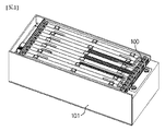
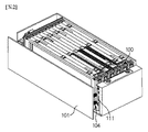
図1は、本発明の望ましい実施例によるバッテリーモジュールの構成を示した一部の分解斜視図であり、図2は、図1からカバープレートが分離した状態を示す斜視図である。 FIG. 1 is a partially exploded perspective view illustrating a configuration of a battery module according to a preferred embodiment of the present invention, and FIG. 2 is a perspective view illustrating a state where a cover plate is separated from FIG.
図1及び図2を参照すれば、本発明の望ましい実施例によるバッテリーモジュールは、セルアセンブリー100、セルアセンブリー100の外面を覆うカバープレート101、カバープレート101の結合時、弾性力及び磁気力を各々提供するばね部材104及びマグネット107を含む。
Referring to FIGS. 1 and 2, a battery module according to a preferred embodiment of the present invention includes a
セルアセンブリー100をなす各々のセルは、薄板状の本体を有するものであって、望ましくはパウチ型二次電池によって構成される。複数のセルは、セルアセンブリー100の一方向に配列され、実質的に積層構造をなす。
Each cell constituting the
セルアセンブリー100の少なくとも一端部には、ターミナルバスバー111が設けられ、セルに付着したリード110と電気的に接続する。図3に示したように、リード110とターミナルバスバー111とは実質的に対向するように配置され、カバープレート101の結合時に加えられるばね部材104の弾性力とマグネット107の磁気力によって相互密着する。
A
カバープレート101は、セルアセンブリー100の最外側を覆うように配置され、セルを保護及び固定する。カバープレート101は、セルアセンブリー100に機械的剛性を提供し、外部の衝撃などからセルアセンブリー100を保護する役割を果たす。カバープレート101をセルアセンブリー100の最外側に結合及び固定するための手段としては、ボルトや溝/突起構造のような通常の締結手段が採用できる。
The
ばね部材104は、カバープレート101によって加圧され、リード110とターミナルバスバー111との間に弾性力を加えることで、リード110とターミナルバスバー111とを相互強く密着させる作用をする。後述する磁気力を中心に均衡的な弾性力を提供するために、ばね部材104は鉄片部材105を中心に上下対称になるように配置することが望ましい。
The
図4に示したように、ばね部材104は、ターミナルバスバー111の外面に密着可能な支持部材103と、支持部材103の両突出部に各々嵌合する第1ばね104a及び第2ばね104bを含む。第1ばね104aは、所定形状の絶縁カバー102の内に収容され、第2ばね104bは、望ましくはターミナルバスバー111を貫くように配置される。
As shown in FIG. 4, the
マグネット107は、リード110の内側面に配置され、リード110とターミナルバスバー111とをさらに密に密着するための磁気力を提供する。ここで、ターミナルバスバー111の外面には、マグネット107との磁気的相互作用が可能な所定形状の鉄片部材105がマグネット107と対向するように配置される。鉄片部材105は、ブロック形態または薄板形態からなる。
The
セルアセンブリー100へのカバープレート101の結合時、マグネット107と鉄片部材105との間には互いに引っ張る方向へ磁気力が作用し、リード110とターミナルバスバー111とをさらに強く密着させるように作用する。
When the
カバープレート101とターミナルバスバー111との間には、ばね部材104及び鉄片部材105を支持する絶縁カバー102を備えることが望ましい。
It is desirable that an
図5及び図6には、本発明の望ましい実施例によるバッテリーモジュールの電気的接続状態および分離状態が各々示されている。 FIGS. 5 and 6 show an electrical connection state and a disconnection state of a battery module according to a preferred embodiment of the present invention, respectively.
図5に示したように、カバープレート101が結合した状態では、前述のようにばね部材104が圧縮されてターミナルバスバー111に弾性力を加え、これとともにマグネット107と鉄片部材105との間に引力が作用するため、ターミナルバスバー111とリード110とが相互密着して電気的接続状態を維持する。
As shown in FIG. 5, when the
一方、過充電などによってセルアセンブリー100が膨脹し、図6に示したようにカバープレート101の外郭方向に変位が発生したときは、ばね部材104が弾性復元されながらターミナルバスバー111とリード110とがマグネット107と鉄片部材105との引力を超えて分離され、電気的接続が遮断される。この過程で、ターミナルバスバー111は、第2ばね104bと連動してリード110から分離されることが望ましい。
On the other hand, when the
前記のような構成を有する本発明の望ましい実施例によるバッテリーモジュールは、セルの過充電などによってスウェリングが発生したとき、電気的遮断のための制御装置に誤作動が発生しても、スウェリングによる変位を用いてばね部材104及びマグネット107による締結力を解除することで、リード110とターミナルバスバー111との接触を信頼性よく分離して過充電を防止することができる。
In the battery module having the above-described configuration according to an embodiment of the present invention, when swelling occurs due to overcharging of a cell or the like, even if a malfunction occurs in a control device for electrical disconnection, swelling may occur. By releasing the fastening force of the
以上のように、本発明を限定された実施例と図面によって説明したが、本発明はこれに限定されるものではなく、本発明の属する技術分野で通常の知識を持つ者によって本発明の技術思想と特許請求の範囲の均等範囲内で多様な修正及び変形が可能であることは言うまでもない。 As described above, the present invention has been described with reference to the limited embodiment and the drawings. However, the present invention is not limited to this, and a person having ordinary knowledge in the technical field to which the present invention pertains. It goes without saying that various modifications and variations are possible within the scope of the spirit and scope of the claims.
本発明を適用する場合、セルリードとターミナルバスバーとの接触を信頼性よく分離して過充電を防止することで、バッテリーモジュールの安全性を向上させることができる。 When the present invention is applied, the safety of the battery module can be improved by reliably separating the contact between the cell lead and the terminal bus bar to prevent overcharging.
100 セルアセンブリー
101 カバープレート
102 絶縁カバー
103 支持部材
104 ばね部材
第1ばね104a
第2ばね104b
105 鉄片部材
107 マグネット
110 リード
111 ターミナルバスバー
REFERENCE SIGNS LIST 100
105
Claims (5)
前記リードと接触可能に対向して配置されるターミナルバスバーと、
前記セルアセンブリーに結合するカバープレートによって加圧され、前記リードと前記ターミナルバスバーとの間に弾性力を加えるばね部材と、
前記リード及び前記ターミナルバスバーの少なくとも一方に配置され、前記リードと前記ターミナルバスバーとを相互密着させる磁気力を提供するマグネットと、
を含み、
前記カバープレートが外郭方向に変位した場合に、前記ばね部材が弾性復元により前記リードと前記ターミナルバスバーとを分離する、バッテリーモジュール。 A cell assembly in which cells to which leads are attached are arranged;
A terminal bus bar arranged so as to be capable of contacting the lead;
A spring member that is pressed by a cover plate coupled to the cell assembly and applies an elastic force between the lead and the terminal bus bar;
A magnet that is disposed on at least one of the lead and the terminal bus bar and that provides a magnetic force for bringing the lead and the terminal bus bar into close contact with each other;
Only including,
The battery module , wherein when the cover plate is displaced in the outer direction, the spring member separates the lead and the terminal bus bar by elastic recovery .
前記ターミナルバスバーの外面には、前記マグネットとの磁気的相互作用が可能な鉄片部材が前記マグネットに対向して配置されていることを特徴とする、請求項1に記載のバッテリーモジュール。 The magnet is disposed on an inner surface of the lead,
The battery module according to claim 1, wherein an iron piece member capable of magnetic interaction with the magnet is disposed on an outer surface of the terminal bus bar so as to face the magnet.
前記第1ばねが、前記絶縁カバー内に収容され、前記第2ばねが、前記ターミナルバスバーを貫くように配置されることを特徴とする、請求項3に記載のバッテリーモジュール。 The spring member includes a first spring and a second spring provided on both sides of a support member that can be in close contact with an outer surface of the terminal bus bar,
4. The battery module according to claim 3, wherein the first spring is housed in the insulating cover, and the second spring is disposed to penetrate the terminal bus bar. 5.
Applications Claiming Priority (3)
| Application Number | Priority Date | Filing Date | Title |
|---|---|---|---|
| KR10-2016-0015155 | 2016-02-05 | ||
| KR1020160015155A KR102010017B1 (en) | 2016-02-05 | 2016-02-05 | Secondary battery module improved in preventing structure of battery overcharge |
| PCT/KR2017/001302 WO2017135796A1 (en) | 2016-02-05 | 2017-02-06 | Battery module having improved over-charge prevention structure |
Publications (2)
| Publication Number | Publication Date |
|---|---|
| JP2018532239A JP2018532239A (en) | 2018-11-01 |
| JP6664475B2 true JP6664475B2 (en) | 2020-03-13 |
Family
ID=59500403
Family Applications (1)
| Application Number | Title | Priority Date | Filing Date |
|---|---|---|---|
| JP2018521058A Active JP6664475B2 (en) | 2016-02-05 | 2017-02-06 | Battery module with improved overcharge prevention structure |
Country Status (7)
| Country | Link |
|---|---|
| US (1) | US10553850B2 (en) |
| EP (1) | EP3358645B1 (en) |
| JP (1) | JP6664475B2 (en) |
| KR (1) | KR102010017B1 (en) |
| CN (1) | CN108352478B (en) |
| PL (1) | PL3358645T3 (en) |
| WO (1) | WO2017135796A1 (en) |
Families Citing this family (6)
| Publication number | Priority date | Publication date | Assignee | Title |
|---|---|---|---|---|
| KR102364283B1 (en) * | 2017-12-01 | 2022-02-16 | 주식회사 엘지에너지솔루션 | Battery Module Having Heat Dissipation Plate |
| KR102270828B1 (en) | 2017-12-19 | 2021-06-29 | 주식회사 엘지에너지솔루션 | Battery Module Having Bus-Bar Assembly |
| KR102275879B1 (en) | 2018-03-12 | 2021-07-08 | 주식회사 엘지에너지솔루션 | Auxiliary Battery storage device for Electric vehicle |
| KR102607280B1 (en) * | 2019-02-01 | 2023-11-27 | 주식회사 엘지에너지솔루션 | Battery assembly capable of simultaneous application of mechanical pressing and magnetic pressing to battery cell |
| EP4278408A1 (en) * | 2021-01-14 | 2023-11-22 | Molex, LLC | Contact interface for electrically coupling battery cells |
| CN114388975B (en) * | 2021-12-16 | 2023-06-09 | 杭州申昊科技股份有限公司 | Battery pack for intelligent inspection robot |
Family Cites Families (21)
| Publication number | Priority date | Publication date | Assignee | Title |
|---|---|---|---|---|
| US3914723A (en) * | 1974-07-15 | 1975-10-21 | Price Edison Inc | Positive action magnetic latching relay |
| JPH10294097A (en) | 1997-02-24 | 1998-11-04 | Mitsubishi Electric Corp | Thin type cell |
| JP3882267B2 (en) * | 1997-05-29 | 2007-02-14 | 新神戸電機株式会社 | Battery power supply |
| KR100702800B1 (en) * | 2004-06-14 | 2007-04-03 | 주식회사 엘지화학 | Secondary battery with improvement of safty |
| KR100881641B1 (en) | 2005-05-10 | 2009-02-04 | 주식회사 엘지화학 | Middle or Large-sized Battery Pack Having Safety System |
| JP5220588B2 (en) | 2005-05-02 | 2013-06-26 | エルジー・ケム・リミテッド | Medium or large improved battery pack with improved safety |
| KR100760751B1 (en) * | 2005-12-23 | 2007-09-21 | 삼성에스디아이 주식회사 | Secondary battery |
| KR100836410B1 (en) * | 2006-11-28 | 2008-06-09 | 현대자동차주식회사 | Battery for a electric vehicle |
| JP4680940B2 (en) * | 2007-01-10 | 2011-05-11 | キヤノン電子株式会社 | Battery device |
| JP5234731B2 (en) | 2007-11-06 | 2013-07-10 | Necエナジーデバイス株式会社 | Battery pack |
| KR101016596B1 (en) * | 2009-01-29 | 2011-02-22 | 강정욱 | Cell cartridge |
| JP2010255840A (en) * | 2009-03-31 | 2010-11-11 | Honda Motor Co Ltd | Clutch actuator structure |
| US8541117B2 (en) | 2009-11-11 | 2013-09-24 | Blackberry Limited | Low noise battery with a magnetic compensation structure for wireless mobile communication device |
| US8361646B2 (en) * | 2010-03-15 | 2013-01-29 | Electronvault, Inc. | Modular interconnection system |
| KR20140097681A (en) * | 2013-01-28 | 2014-08-07 | 삼성에스디아이 주식회사 | Battery pack, method of welding tab of back, and battery pack control system |
| KR101495227B1 (en) * | 2013-09-12 | 2015-02-24 | 송암시스콤 주식회사 | Portable battery |
| KR101500222B1 (en) | 2013-12-18 | 2015-03-06 | 현대자동차주식회사 | Apparatus for preventing over charging of battery |
| CN105024023A (en) * | 2014-04-30 | 2015-11-04 | 江苏智航新能源有限公司 | Handle used for lithium batteries |
| GB2529612A (en) | 2014-06-25 | 2016-03-02 | R & D Vehicle Systems Ltd | Device for a battery assembly |
| JP6359362B2 (en) | 2014-07-07 | 2018-07-18 | 株式会社東芝 | Battery module |
| JP6365186B2 (en) * | 2014-09-29 | 2018-08-01 | 豊田合成株式会社 | Busbar module |
-
2016
- 2016-02-05 KR KR1020160015155A patent/KR102010017B1/en active IP Right Grant
-
2017
- 2017-02-06 WO PCT/KR2017/001302 patent/WO2017135796A1/en active Application Filing
- 2017-02-06 EP EP17747839.3A patent/EP3358645B1/en active Active
- 2017-02-06 PL PL17747839.3T patent/PL3358645T3/en unknown
- 2017-02-06 CN CN201780003703.1A patent/CN108352478B/en active Active
- 2017-02-06 JP JP2018521058A patent/JP6664475B2/en active Active
- 2017-02-06 US US15/770,693 patent/US10553850B2/en active Active
Also Published As
| Publication number | Publication date |
|---|---|
| US10553850B2 (en) | 2020-02-04 |
| US20190058183A1 (en) | 2019-02-21 |
| EP3358645A4 (en) | 2019-02-20 |
| CN108352478A (en) | 2018-07-31 |
| EP3358645B1 (en) | 2022-04-27 |
| KR20170093577A (en) | 2017-08-16 |
| WO2017135796A1 (en) | 2017-08-10 |
| PL3358645T3 (en) | 2022-08-01 |
| CN108352478B (en) | 2020-11-17 |
| EP3358645A1 (en) | 2018-08-08 |
| JP2018532239A (en) | 2018-11-01 |
| KR102010017B1 (en) | 2019-08-12 |
Similar Documents
| Publication | Publication Date | Title |
|---|---|---|
| JP6664475B2 (en) | Battery module with improved overcharge prevention structure | |
| JP6258272B2 (en) | Battery module | |
| CN110168779B (en) | Pouch-shaped secondary battery including electrode tab cutting device | |
| JP5002958B2 (en) | battery | |
| KR101704127B1 (en) | Battery system improving operational reliability of swelling cid | |
| KR101294179B1 (en) | Apparatus for preventing overcharge battery | |
| US10418619B2 (en) | Top cover of power battery and power battery | |
| KR20170138746A (en) | Battery Pack | |
| KR101792820B1 (en) | Battery Pack Comprising Terminal Connecting Member with Breakable Portion and Damping Member | |
| JP2015115267A (en) | Power storage device comprising current breaking device | |
| JP6435883B2 (en) | Battery module and battery module disassembly method | |
| JP2021052020A (en) | Secondary battery and secondary battery assembly | |
| US8383259B2 (en) | Safety device for an accumulator cell | |
| KR20140084564A (en) | Cell module assembly for vehicle battery | |
| JP6111856B2 (en) | Power storage device | |
| KR102341404B1 (en) | Battery module | |
| JP6142888B2 (en) | Power storage device with current interrupt device | |
| KR20220018735A (en) | Battery pack having current interrupt apparatus using bi-metal, and operation method thereof | |
| JP6041008B2 (en) | Power storage device with current interrupt device | |
| JP6519129B2 (en) | Method of manufacturing power storage device | |
| JP6142887B2 (en) | Power storage device with current interrupt device | |
| JP2015115328A (en) | Power storage device comprising current breaking device | |
| JP6142886B2 (en) | Power storage device with current interrupt device | |
| JP2018147647A (en) | battery | |
| JP2017174655A (en) | Battery pack and method of manufacturing battery pack |
Legal Events
| Date | Code | Title | Description |
|---|---|---|---|
| A621 | Written request for application examination |
Free format text: JAPANESE INTERMEDIATE CODE: A621 Effective date: 20180423 |
|
| A131 | Notification of reasons for refusal |
Free format text: JAPANESE INTERMEDIATE CODE: A131 Effective date: 20190603 |
|
| A521 | Request for written amendment filed |
Free format text: JAPANESE INTERMEDIATE CODE: A523 Effective date: 20190821 |
|
| TRDD | Decision of grant or rejection written | ||
| A01 | Written decision to grant a patent or to grant a registration (utility model) |
Free format text: JAPANESE INTERMEDIATE CODE: A01 Effective date: 20200127 |
|
| A61 | First payment of annual fees (during grant procedure) |
Free format text: JAPANESE INTERMEDIATE CODE: A61 Effective date: 20200218 |
|
| R150 | Certificate of patent or registration of utility model |
Ref document number: 6664475 Country of ref document: JP Free format text: JAPANESE INTERMEDIATE CODE: R150 |
|
| S111 | Request for change of ownership or part of ownership |
Free format text: JAPANESE INTERMEDIATE CODE: R313111 |
|
| R350 | Written notification of registration of transfer |
Free format text: JAPANESE INTERMEDIATE CODE: R350 |
|
| R250 | Receipt of annual fees |
Free format text: JAPANESE INTERMEDIATE CODE: R250 |
|
| R250 | Receipt of annual fees |
Free format text: JAPANESE INTERMEDIATE CODE: R250 |