JP6664331B2 - Mechanical joints and related systems and methods - Google Patents
Mechanical joints and related systems and methods Download PDFInfo
- Publication number
- JP6664331B2 JP6664331B2 JP2016553459A JP2016553459A JP6664331B2 JP 6664331 B2 JP6664331 B2 JP 6664331B2 JP 2016553459 A JP2016553459 A JP 2016553459A JP 2016553459 A JP2016553459 A JP 2016553459A JP 6664331 B2 JP6664331 B2 JP 6664331B2
- Authority
- JP
- Japan
- Prior art keywords
- joint
- wrist
- actuation element
- actuation
- length
- Prior art date
- Legal status (The legal status is an assumption and is not a legal conclusion. Google has not performed a legal analysis and makes no representation as to the accuracy of the status listed.)
- Active
Links
- 238000000034 method Methods 0.000 title description 20
- 210000000707 wrist Anatomy 0.000 claims description 152
- 238000005452 bending Methods 0.000 claims description 121
- 239000012636 effector Substances 0.000 claims description 71
- 230000006835 compression Effects 0.000 claims description 15
- 238000007906 compression Methods 0.000 claims description 15
- 230000007246 mechanism Effects 0.000 claims description 14
- 239000000463 material Substances 0.000 claims description 13
- 230000005540 biological transmission Effects 0.000 claims description 11
- 238000001356 surgical procedure Methods 0.000 claims description 8
- 239000011248 coating agent Substances 0.000 claims description 7
- 238000000576 coating method Methods 0.000 claims description 7
- 238000010276 construction Methods 0.000 claims description 3
- 230000003313 weakening effect Effects 0.000 claims description 2
- 239000002184 metal Substances 0.000 claims 1
- 230000008859 change Effects 0.000 description 50
- 230000007935 neutral effect Effects 0.000 description 23
- 230000033001 locomotion Effects 0.000 description 16
- 230000004907 flux Effects 0.000 description 8
- 230000004913 activation Effects 0.000 description 6
- 238000010586 diagram Methods 0.000 description 6
- 230000006870 function Effects 0.000 description 6
- 230000008901 benefit Effects 0.000 description 5
- 230000000670 limiting effect Effects 0.000 description 5
- 238000005520 cutting process Methods 0.000 description 4
- 230000002441 reversible effect Effects 0.000 description 4
- 210000003857 wrist joint Anatomy 0.000 description 4
- 238000013461 design Methods 0.000 description 3
- 238000012423 maintenance Methods 0.000 description 3
- 238000004519 manufacturing process Methods 0.000 description 3
- 239000002861 polymer material Substances 0.000 description 3
- 229920001343 polytetrafluoroethylene Polymers 0.000 description 3
- 239000004810 polytetrafluoroethylene Substances 0.000 description 3
- 238000012545 processing Methods 0.000 description 3
- 239000007787 solid Substances 0.000 description 3
- 229920002614 Polyether block amide Polymers 0.000 description 2
- 239000004020 conductor Substances 0.000 description 2
- 230000000994 depressogenic effect Effects 0.000 description 2
- 230000000694 effects Effects 0.000 description 2
- 229920000840 ethylene tetrafluoroethylene copolymer Polymers 0.000 description 2
- 230000036961 partial effect Effects 0.000 description 2
- 229920000642 polymer Polymers 0.000 description 2
- -1 polytetrafluoroethylene Polymers 0.000 description 2
- 239000010935 stainless steel Substances 0.000 description 2
- 229910001220 stainless steel Inorganic materials 0.000 description 2
- 210000002435 tendon Anatomy 0.000 description 2
- 229920001169 thermoplastic Polymers 0.000 description 2
- 239000004416 thermosoftening plastic Substances 0.000 description 2
- 239000004812 Fluorinated ethylene propylene Substances 0.000 description 1
- 101100289792 Squirrel monkey polyomavirus large T gene Proteins 0.000 description 1
- 229910000831 Steel Inorganic materials 0.000 description 1
- 238000002679 ablation Methods 0.000 description 1
- 238000013459 approach Methods 0.000 description 1
- 230000008878 coupling Effects 0.000 description 1
- 238000010168 coupling process Methods 0.000 description 1
- 238000005859 coupling reaction Methods 0.000 description 1
- 238000002788 crimping Methods 0.000 description 1
- 230000003247 decreasing effect Effects 0.000 description 1
- QHSJIZLJUFMIFP-UHFFFAOYSA-N ethene;1,1,2,2-tetrafluoroethene Chemical group C=C.FC(F)=C(F)F QHSJIZLJUFMIFP-UHFFFAOYSA-N 0.000 description 1
- HQQADJVZYDDRJT-UHFFFAOYSA-N ethene;prop-1-ene Chemical group C=C.CC=C HQQADJVZYDDRJT-UHFFFAOYSA-N 0.000 description 1
- 230000002262 irrigation Effects 0.000 description 1
- 238000003973 irrigation Methods 0.000 description 1
- 238000009940 knitting Methods 0.000 description 1
- 238000005259 measurement Methods 0.000 description 1
- 238000012986 modification Methods 0.000 description 1
- 230000004048 modification Effects 0.000 description 1
- 229920009441 perflouroethylene propylene Polymers 0.000 description 1
- 229920001296 polysiloxane Polymers 0.000 description 1
- 230000008569 process Effects 0.000 description 1
- 230000002829 reductive effect Effects 0.000 description 1
- 230000007480 spreading Effects 0.000 description 1
- 238000003892 spreading Methods 0.000 description 1
- 239000010959 steel Substances 0.000 description 1
- 238000004804 winding Methods 0.000 description 1
Images


Classifications
-
- A—HUMAN NECESSITIES
- A61—MEDICAL OR VETERINARY SCIENCE; HYGIENE
- A61B—DIAGNOSIS; SURGERY; IDENTIFICATION
- A61B34/00—Computer-aided surgery; Manipulators or robots specially adapted for use in surgery
-
- A—HUMAN NECESSITIES
- A61—MEDICAL OR VETERINARY SCIENCE; HYGIENE
- A61B—DIAGNOSIS; SURGERY; IDENTIFICATION
- A61B34/00—Computer-aided surgery; Manipulators or robots specially adapted for use in surgery
- A61B34/30—Surgical robots
- A61B34/35—Surgical robots for telesurgery
-
- A—HUMAN NECESSITIES
- A61—MEDICAL OR VETERINARY SCIENCE; HYGIENE
- A61B—DIAGNOSIS; SURGERY; IDENTIFICATION
- A61B34/00—Computer-aided surgery; Manipulators or robots specially adapted for use in surgery
- A61B34/30—Surgical robots
- A61B34/37—Master-slave robots
-
- A—HUMAN NECESSITIES
- A61—MEDICAL OR VETERINARY SCIENCE; HYGIENE
- A61B—DIAGNOSIS; SURGERY; IDENTIFICATION
- A61B34/00—Computer-aided surgery; Manipulators or robots specially adapted for use in surgery
- A61B34/70—Manipulators specially adapted for use in surgery
- A61B34/71—Manipulators operated by drive cable mechanisms
-
- A—HUMAN NECESSITIES
- A61—MEDICAL OR VETERINARY SCIENCE; HYGIENE
- A61B—DIAGNOSIS; SURGERY; IDENTIFICATION
- A61B90/00—Instruments, implements or accessories specially adapted for surgery or diagnosis and not covered by any of the groups A61B1/00 - A61B50/00, e.g. for luxation treatment or for protecting wound edges
- A61B90/36—Image-producing devices or illumination devices not otherwise provided for
- A61B90/361—Image-producing devices, e.g. surgical cameras
-
- A—HUMAN NECESSITIES
- A61—MEDICAL OR VETERINARY SCIENCE; HYGIENE
- A61B—DIAGNOSIS; SURGERY; IDENTIFICATION
- A61B90/00—Instruments, implements or accessories specially adapted for surgery or diagnosis and not covered by any of the groups A61B1/00 - A61B50/00, e.g. for luxation treatment or for protecting wound edges
- A61B90/36—Image-producing devices or illumination devices not otherwise provided for
- A61B90/37—Surgical systems with images on a monitor during operation
-
- A—HUMAN NECESSITIES
- A61—MEDICAL OR VETERINARY SCIENCE; HYGIENE
- A61B—DIAGNOSIS; SURGERY; IDENTIFICATION
- A61B17/00—Surgical instruments, devices or methods, e.g. tourniquets
- A61B17/00234—Surgical instruments, devices or methods, e.g. tourniquets for minimally invasive surgery
- A61B2017/00292—Surgical instruments, devices or methods, e.g. tourniquets for minimally invasive surgery mounted on or guided by flexible, e.g. catheter-like, means
- A61B2017/003—Steerable
- A61B2017/00305—Constructional details of the flexible means
-
- A—HUMAN NECESSITIES
- A61—MEDICAL OR VETERINARY SCIENCE; HYGIENE
- A61B—DIAGNOSIS; SURGERY; IDENTIFICATION
- A61B17/00—Surgical instruments, devices or methods, e.g. tourniquets
- A61B17/28—Surgical forceps
- A61B17/29—Forceps for use in minimally invasive surgery
- A61B2017/2901—Details of shaft
- A61B2017/2905—Details of shaft flexible
-
- A—HUMAN NECESSITIES
- A61—MEDICAL OR VETERINARY SCIENCE; HYGIENE
- A61B—DIAGNOSIS; SURGERY; IDENTIFICATION
- A61B34/00—Computer-aided surgery; Manipulators or robots specially adapted for use in surgery
- A61B34/30—Surgical robots
- A61B2034/302—Surgical robots specifically adapted for manipulations within body cavities, e.g. within abdominal or thoracic cavities
-
- A—HUMAN NECESSITIES
- A61—MEDICAL OR VETERINARY SCIENCE; HYGIENE
- A61B—DIAGNOSIS; SURGERY; IDENTIFICATION
- A61B34/00—Computer-aided surgery; Manipulators or robots specially adapted for use in surgery
- A61B34/30—Surgical robots
- A61B2034/305—Details of wrist mechanisms at distal ends of robotic arms
- A61B2034/306—Wrists with multiple vertebrae
Description
(関連出願の参照)
この出願は、2014年2月21日に出願された米国仮出願第61/943,084号の利益を主張し、その全文をここに参照として援用する。
(Refer to related applications)
This application claims the benefit of US Provisional Application No. 61 / 943,084, filed February 21, 2014, which is incorporated herein by reference in its entirety.
本開示は、機械的な関節を関節作動させるために作動要素を利用する、機械的な関節構造及び器具及び方法に関する。具体的には、本開示の特徴は、遠隔関節作動可能な機械的な関節を利用する、手術器具及び方法に関する。 The present disclosure relates to mechanical articulation structures and instruments and methods that utilize actuation elements to articulate mechanical joints. In particular, aspects of the present disclosure relate to surgical instruments and methods that utilize a remotely articulatable mechanical joint.
遠隔操作手術器具を含む遠隔制御手術器具が、最小侵襲的な医療処置においてしばしば用いられる。医療処置中、手術器具は、1つ又はそれよりも多くの方向に関節作動させられることがある。例えば、手術器具は、手術器具の遠位端に配置されるエンドエフェクタを所望の場所において方向付け且つ位置付けるために、手術器具シャフトの近位端で伝動機構によって作動させられることがある。手術器具は、エンドエフェクタがシャフトに対して位置付けられてよいように、エンドエフェクタが接続される、関節付き関節作動可能な構造のような、リスト(手首関節)を更に含んでよい。手術器具は、エンドエフェクタを作動させるよう、リストを含む、手術器具を通じて進む、1つ又はそれよりも多くのエンドエフェクタ作動要素を更に含んでよい。リストを関節作動させること(曲げること)は、(複数の)エンドエフェクタ作動要素の曲げをもたらすことがあり、それは(複数の)エンドエフェクタ作動要素の長さの変化をもたらすことがある。そのような長さの変化は、エンドエフェクタの意図されない動きを引き起こし得る。これに鑑みれば、器具のリストが関節作動させられるときに、作動要素の長さを実質的に維持する(conserve)ように構成される、1つ又はそれよりも多くのエンドエフェクタ作動要素を含む手術器具を提供するのが望ましいことがある。 Remotely controlled surgical instruments, including remotely operated surgical instruments, are often used in minimally invasive medical procedures. During a medical procedure, a surgical instrument may be articulated in one or more directions. For example, a surgical instrument may be actuated by a transmission mechanism at a proximal end of a surgical instrument shaft to direct and position an end effector located at a distal end of the surgical instrument at a desired location. The surgical instrument may further include a wrist (wrist joint), such as an articulated, articulatable structure to which the end effector is connected, such that the end effector may be positioned relative to the shaft. The surgical instrument may further include one or more end effector actuation elements that are advanced through the surgical instrument, including the wrist, to actuate the end effector. Articulating (bending) the wrist may result in bending of the end effector (s), which may result in a change in the length of the end effector (s). Such a change in length can cause unintended movement of the end effector. In view of this, the instrument list includes one or more end effector actuation elements configured to substantially conserve the length of the actuation elements when articulated. It may be desirable to provide a surgical instrument.
本開示の例示的な実施態様は、上述の課題のうちの1つ又はそれよりも多くを解決することがあり、且つ/或いは、上述の望ましい構成のうちの1つ又はそれよりも多くを実証することがある。他の構成及び/又は利点は、後続の記述から明らかになることがある。 Example embodiments of the present disclosure may solve one or more of the above-mentioned problems and / or demonstrate one or more of the above-described desirable configurations. May be. Other configurations and / or advantages may become apparent from the description that follows.
少なくとも1つの例示的な実施態様によれば、手術器具は、第1の端にリストを含むシャフトと、リストに連結されるエンドエフェクタと、シャフト及びリストに沿って延びる作動要素とを含んでよい。作動要素は、リストの少なくとも部分に沿う捩れ経路(twisted path)に従ってよい。捩れ経路は、リストの全長に沿って360度未満の角度的な広がり(angular extent)を有してよい。 According to at least one example embodiment, a surgical instrument may include a shaft including a wrist at a first end, an end effector coupled to the wrist, and an actuation element extending along the shaft and the wrist. . The actuation element may follow a twisted path along at least a portion of the list. The twist path may have an angular extent of less than 360 degrees along the entire length of the wrist.
他の例示的な実施態様によれば、手術器具の作動要素のための支持構造は、支持構造の長手軸について捩れ経路を定める少なくとも1つの通路を含んでよい。通路は、通路の第1の端から通路の第2の端まで360度未満の角度的な広がりを有してよい。 According to another exemplary embodiment, a support structure for an operating element of a surgical instrument may include at least one passage defining a torsional path about a longitudinal axis of the support structure. The passage may have an angular extent of less than 360 degrees from a first end of the passage to a second end of the passage.
他の例示的な実施態様によれば、手術器具リストを構成する方法は、作動要素がリストの少なくとも部分に沿う捩れ経路に従うよう、作動要素をリストに沿って延ばすことを含んでよい。捩れ経路は、360度未満の角度的な広がりを有してよい。 According to another exemplary embodiment, a method of constructing a surgical instrument list may include extending an actuation element along a wrist such that the actuation element follows a torsional path along at least a portion of the wrist. The twist path may have an angular extent of less than 360 degrees.
追加的な目的、構成、及び/又は利点は、後続の記述に部分的に示され、その記載から部分的に明らかであり、或いは本開示及び/又は請求項の実施によって学習されることがある。これらの目的及び利点の少なくとも一部が、付属の請求項において特に指摘される要素及び組み合わせによって実現されることがあり且つ得られることがある。 Additional objects, features, and / or advantages will be set forth in part in the description which follows, and in part will be obvious from the description, or may be learned by practice of the disclosure and / or the claims. . At least some of these objectives and advantages may be realized and obtained by means of the elements and combinations particularly pointed out in the appended claims.
前述の一般的な記述及び後続の詳細な記述の両方は、例示的且つ例証的であるに過ぎず、請求項を限定しない。むしろ、請求項は、均等物を含む、それらの全幅の広さを得る権利がある。 Both the foregoing general description and the following detailed description are exemplary and explanatory only and are not restrictive of the claims. Rather, the claims are entitled to their full breadth, including equivalents.
本開示は、以下の詳細な記述のみから或いは添付の図面と一緒に理解され得る。図面は、本開示の更なる理解をもたらすために含められ、この明細書に組み込まれ且つこの明細書の一部を構成する。図面は、本教示の1つ又はそれよりも多くの例示的な実施態様を例示し、本記述と一緒に、特定の原理及び動作を説明する役割を果たす。 The present disclosure may be understood from the following detailed description only or in conjunction with the accompanying drawings. The drawings are included to provide a further understanding of the present disclosure, are incorporated in and constitute a part of this specification. The drawings illustrate one or more exemplary embodiments of the present teachings and, together with the description, serve to explain certain principles and operations.
例示的な実施態様を例示するこの記述及び添付の図面は、限定的であると理解されてはならない。均等物を含む、この記述及び請求項の範囲から逸脱せずに、様々な機械的、組成的、構造的、電気的、及び動作的な変更を行ってよい。幾つかの場合には、開示を曖昧にしないよう、周知の構造及び技法を詳細に示さず或いは記載しない。2つ又はそれよりも多くの図面における同等の番号は、同一の又は類似の要素を示す。更に、1つの実施態様を参照して詳細に記載される要素及びそれらの関連する構成は、実際的である限り、それらを特に示さず或いは記載しない他の実施態様に含められてよい。例えば、ある要素が1つの実施態様を参照して詳細に記載され、第2の実施態様を参照して記載されていないならば、その要素は、それにも拘わらず、第2の実施態様に含められているものとして請求されてよい。 This description and the accompanying drawings, which illustrate exemplary embodiments, are not to be understood as limiting. Various mechanical, compositional, structural, electrical, and operational changes may be made without departing from the scope of the description and claims, including equivalents. In some instances, well-known structures and techniques are not shown or described in detail so as not to obscure the disclosure. Equivalent numbers in two or more figures indicate the same or similar elements. Furthermore, elements and their associated features described in detail with reference to one embodiment may be included in other embodiments that do not specifically show or describe them as long as practical. For example, if an element is described in detail with reference to one embodiment, and is not described with reference to a second embodiment, then that element is nonetheless included in the second embodiment. May be claimed.
この明細書及び付属の請求項の目的のために、その他のことが示されない限り、量、割合、又は比率、並びに明細書及び請求項中で用いられる他の数値は、全ての場合において、それらが既にそのように修飾されていない限りにおいて、「約」という用語によって修飾されるものとして理解されなければならない。従って、逆のことが示されない限り、以下の明細書及び付属の請求項中に示される数値パラメータは、取得されることが探究される所望の特性に依存して異なることがある、近似である。最低限でも、そして、均等論の適用を請求項の範囲に限定する試みとしてではなく、各数値パラメータは、少なくとも、公表有効数字の数の観点から並びに通常の丸め技法を適用することによって、解釈されなければならない。 For the purposes of this specification and the appended claims, unless otherwise indicated, amounts, ratios, or ratios, and other values used in the specification and claims, are Has to be understood as being modified by the term "about", unless it has already been so modified. Thus, unless expressly indicated to the contrary, the numerical parameters set forth in the following specification and the appended claims are approximations, which may be different depending on the desired property sought to be obtained. . At a minimum, and not as an attempt to limit the application of the doctrine of equivalents to the scope of the claims, each numerical parameter must be interpreted, at least in terms of the number of significant figures published and by applying ordinary rounding techniques. It must be.
この明細書及び付属の請求項において用いられるとき、単数形及びいずれかの用語の単数の使用は、明示的に明白に1つの指示物(referent)に限定されない限り、複数の指示物を含む。ここにおいて用いるとき、「含む」という用語及びその文法的な変形は、あるリスト中の品目の引用が、その列挙される品目と置換され得る或いはその列挙される品目に追加され得る、他の同等の品目を排除しないよう、非限定的であることを意図する。 As used in this specification and the appended claims, the use of the singular and the singular of any term include the plural referent unless expressly limited to one referent. As used herein, the term "comprising" and its grammatical variants are used to refer to items in a list that may be replaced with, or added to, the listed item (s) by other equivalents. It is intended to be non-limiting so as not to exclude items of
更に、この記述の用語法(terminology)は、本開示又は請求項を限定することを意図しない。例えば、「下」(“beneath”)、「下」(“below”)、「下方」(“lower”)、「上(に)」(“above”)、「上方」(“upper”)、「近位」(“proximal”)、「遠位」(“distal”)及び同等表現のような−空間的に相対的な用語は、図面中の他の要素又は構成に対する1つの要素の又は構成の関係を記載するために用いられることがある。これらの空間的に相対的な用語は、図面に示す位置及び向きに加えて、使用中又は動作中のデバイスの異なる位置(即ち、場所)及び向き(即ち、回転的配置)を含むことを意図する。例えば、図面中のデバイスが反転させられるならば、他の要素の「下」(“beneath”)又は「下」(“below”)として記載される要素又は構成は、他の要素又は構成の「上」(“above”)又は「上」(“over”)にあるであろう。よって、「下」(“below”)という例示的な用語は、上(“above”)及び下(“below”)の位置及び向きの両方を包摂し得る。デバイスはその他の方向に向けられてよく(90度又は他の向きに回転させられてよく)、ここにおいて用いる空間的に相対的な記述は相応して解釈される。 Furthermore, the terminology of this description is not intended to limit the present disclosure or the claims. For example, “below” (“beneath”), “below” (“below”), “below” (“lower”), “above” (“above”), “upper” (“upper”), Terms such as "proximal", "distal" and equivalents-spatially relative terms are used to refer to one element or configuration relative to another element or configuration in the figures May be used to describe the relationship. These spatially relative terms are intended to include the different positions (ie, locations) and orientations (ie, rotational arrangements) of the device in use or operation, in addition to the locations and orientations shown in the figures. I do. For example, if a device in the drawings is inverted, an element or configuration described as “below” or “below” of another element may be referred to as a “below” of another element or configuration. It may be “above” or “over”. Thus, the exemplary term “below” may encompass both an upper (“above”) and a lower (“below”) position and orientation. The device may be oriented in other directions (rotated 90 degrees or other orientations), and the spatially relative descriptions used herein will be interpreted accordingly.
様々な例示的な実施態様によれば、本開示は、作動要素の少なくとも部分が捩れ経路(twisted path)に沿って配置される、作動要素を利用する遠隔操作手術システムのための手術器具を想定する。作動要素は、エンドエフェクタを作動させるために、リストを関節作動させるために、或いは他の構成部品を作動させるために用いられてよい。更に、例示的な実施態様は、手術器具の中心長手軸(中立軸)から偏心(オフセット)させられるあらゆる作動要素に適用されてよい。例示的な実施態様によれば、捩れ経路は、リストの全長に沿って、リストの中心線に対して、360度未満の角度的な広がり(angular extent)を有してよい。例示的な実施態様によれば、リストが作動するか或いは曲がるときに、作動要素の長さがリストの各関節で維持される(conserved)ように、作動要素の少なくとも部分が、捩れ経路に沿って配置されてよい。作動要素の長さを維持することによって、さもなければリストの曲げ中に生じることがある、作動要素の作動機能と干渉することがある、作動要素の長さの変化が、最小にされることがあり或いは排除されることがある。例示的な実施態様によれば、作動要素は、作動要素の長さがリストの個々の関節で維持されるが、リストの他の個々の関節で維持されず、作動要素の捩れ経路全体が長さ維持構造(length conservative structure)であるように、捩り経路に沿って配置されてよい。 According to various exemplary embodiments, the present disclosure contemplates a surgical instrument for a remotely operated surgical system utilizing an actuating element, wherein at least a portion of the actuating element is disposed along a twisted path. I do. The actuation element may be used to actuate an end effector, articulate a wrist, or actuate other components. Further, the exemplary embodiments may apply to any actuation element that is eccentric (offset) from the central longitudinal axis (neutral axis) of the surgical instrument. According to an exemplary embodiment, the twist path may have an angular extent of less than 360 degrees with respect to the wrist centerline along the entire length of the wrist. According to an exemplary embodiment, at least a portion of the actuation element is moved along a torsional path such that when the wrist is actuated or bent, the length of the actuation element is conserved at each joint of the wrist. May be arranged. By maintaining the length of the actuating element, changes in the length of the actuating element, which may otherwise occur during bending of the wrist, which may interfere with the actuating function of the actuating element, are minimized. Or may be excluded. According to an exemplary embodiment, the actuation element is such that the length of the actuation element is maintained at each individual joint of the wrist, but not at other individual joints of the wrist, and the entire torsional path of the actuation element is long. It may be arranged along a torsional path so as to be a length conservative structure.
本開示は、作動要素支持体を更に想定する。作動要素支持体は、作動要素の長さを維持するために且つ/或いは作動要素の座屈強度を増大させるために、例えば、捩れ経路に沿って、作動要素の少なくとも一部を所望の形状に形作るために用いられてよい。例示的な実施態様によれば、作動要素支持体は、少なくとも1つの管腔を含む一体成形部品であってよく、管腔の少なくとも部分は、捩れ形状を有する。例示的な実施態様によれば、作動要素支持体は、少なくとも1つの剛性部分を含んでよい。作動要素支持体は、例えば、例示的な実施態様に従った、複数の同軸チューブを含んでよい。例示的な実施態様によれば、作動要素支持体は、支持体に可撓性(フレキシビリティ)をもたらすために、切欠き溝のような、1つ又はそれよりも多くの材料弱化領域を備えるチューブを含んでよい。作動要素は、例示的な実施態様に従った、押す動き及び引く動きの両方に有用な、フレキシブルシャフトのような、中空構造を含んでよい。フレキシブルシャフトは、例えば、フィラメントに接続される巻回バネであってよい。他の例示的な実施態様によれば、フレキシブルシャフトは、互いに接続される巻回フィラメントの多数層を含んでよい。 The present disclosure further contemplates an actuation element support. The actuating element support may be used to maintain at least a portion of the actuating element in a desired shape, for example, along a torsion path, to maintain the length of the actuating element and / or to increase the buckling strength of the actuating element. May be used to shape. According to an exemplary embodiment, the actuation element support may be a one-piece component including at least one lumen, at least a portion of the lumen having a twisted shape. According to an exemplary embodiment, the actuation element support may include at least one rigid portion. The actuation element support may include, for example, a plurality of coaxial tubes according to an exemplary embodiment. According to an exemplary embodiment, the actuating element support comprises one or more material weakening areas, such as notches, to provide flexibility to the support. A tube may be included. The actuation element may include a hollow structure, such as a flexible shaft, useful for both pushing and pulling movements, according to an exemplary embodiment. The flexible shaft may be, for example, a wound spring connected to the filament. According to another exemplary embodiment, the flexible shaft may include multiple layers of wound filaments connected to each other.
図1を参照すると、ここに記載する実施態様に従った手術器具を利用し得る、遠隔操作手術システム100の実施例が示されている。例えば、Intuitive Surgical, Inc.から入手可能なda Vinci(登録商標)Surgical Systemであってよい、システム100が、多数の手術器具140を有する患者側カート102を含み、各々の手術器具は、アーム110にある結合ポート内に取り付けられる。アーム110に取り付けられる器具140を特定の医療処置のために選択し得るよう或いは所要の臨床的機能をもたらすために医療措置中に交換し得るよう、器具140は交換可能であり得る。当該技術分野において周知であるように、手術器具140は、例えば、鉗子(forceps)又はグラスパ(graspers)、持針器(needle drivers)、メス(scalpels)、ハサミ(scissors)、焼灼ツール(cauterizing tools)、及びステープラ(staplers)を非限定的に含む、多くの機能を実施し得る。
Referring to FIG. 1, there is shown an example of a remotely operated
各器具140は、概ね、伝動機構又はバックエンド機構150と、伝動機構150から延びる主シャフト160と、主シャフト160の遠位端にある(図1に示さない)任意的なリスト(手首関節)と、リストから延びる或いは主シャフト160から直接的に延びるエンドエフェクタ180とを含む。例えば、図8は、とりわけ、シャフト251と、シャフト251の遠位端にあるリスト250と、リスト250から延びるエンドエフェクタ252とを含む、手術器具の遠位端の1つの例示的な実施態様を例示している。例えば、腱(テンドン)又はロッドのような、作動要素354が、シャフト251を通じてリスト250に及び/又はエンドエフェクタ252に延びてよい。当業者が熟知しているように、作動要素は、プル/プル又はプッシュ/プル作動要素として構成されてよい。プル/プル及びプッシュ/プル作動デバイスの例示的な実施態様が、2013年10月1日に発効した米国特許第8,545,515号に記載されており、その全文をここに参照として援用する。よって、作動要素254は、リスト250及び/又はエンドエフェクタ252を作動させるために用いられてよい。よって、図1を参照すると、作動要素は伝動機構150から延びてよく、伝動機構150は患者側マニピュレータ112に接続されてよい。伝動機構150は、典型的には、患者側カート102内のモータを駆動させるために作動要素の機械的連結をもたらす。例えば、伝動機構150は、患者側カート102のアーム110の患者側マニピュレータ112に接続されるように構成されてよい。結果的に、患者側マニピュレータ112及び伝動機構150は、リスト250及び/又はエンドエフェクタ252を作動させるよう、作動要素254に力を適用するために用いられてよい。更に、図8を再び参照すると、(図8には示されていない)導電体が、シャフト251及びリスト250を通じてエンドエフェクタ252に延びてもよい。
Each
よって、システム100は、リストを動かし或いは位置付けてエンドエフェクタ180を操作するために、必要に応じて作動要素に沿う動き及び力を制御し得る。医療処置を受けている患者にある小さな切開部内のカニューレを通じて手術器具140の端を挿入するために、並びに、患者の内側の作業部位で器具140のリスト及び/又はエンドエフェクタ180を操作するために、患者側カート102のアーム110を用い得る。
Thus, the
カメラ器具104は、患者側カート102のアーム110に同様に取り付けられ得るし、任意的に、作業部位及び患者内の手術器具の動作を見るためにカメラシステム104の遠位端を位置付けるようシステム100が作動する、リストも有し得る。立体視又は三次元であってよい、カメラシステム104からの眺望(view)は、制御コンソール(図示せず)から見ることができ、画像がモニタ106に表示されてよい。よって、システム100の処理システムは、医者又は他の医療関係者がカメラシステム104を見て器具140を操縦するのを可能にするユーザーインターフェースを提供し得る。例えば、手術器具140と同様に、医療処置を受けている患者にある小さな切開部内のカニューレを通じてカメラ器具104の端を挿入するために、並びに、患者の内側の作業部位でリスト及び/又はエンドエフェクタ180を操作するために、アーム110を用い得る。
The
主シャフト160、リスト、及びエンドエフェクタ180の直径又は複数の直径は、概ね、器具を用いるカニューレの大きさに従って選択される。例示的な実施態様において、カメラ器具104の直径並びにリスト及び主シャフト160の直径は、約3mm〜約13mmに及んでよい。例えば、その直径は、幾つかの既存のカニューレシステムの大きさと適合するよう、約4mm、約5mm、約8mm、約10mm、又は約13mmであってよい。
The diameter or diameters of the main shaft 160, the wrist, and the
図1の概略図に例示するように、遠隔操作手術システム100は、外科医コンソール120及び補助的な制御/ビジョンカート130を更に含んでよい。一般的に、外科医コンソール120は、把持機構122及びフットペダル124を非限定的に含む、様々な入力デバイスによる、使用者、例えば、外科医からの入力を受信し、そして、(複数の)手術器具102の所望の動きを実施するよう、相応して、所望の手術処置を遂行するよう、患者側カート102に取り付けられる器具140が応答する、マスタコントローラとしての機能を果たす。例えば、把持機構122は、アーム10で対応する「スレーブ」デバイスとして作用してよい手術器具140及び/又はカメラ器具104を制御することがある、「マスタ」デバイスとして作用してよいが、それに限定されない。例えば、把持機構122は、当業者が熟知しているように、手術器具140のリスト及び/又はエンドエフェクタ180を制御してよい。更に、例えば、モノポーラ又はバイポーラ電気手術エネルギをもたらすために、或いは、器具140の様々な他の機能(例えば、吸引(suction)、洗浄(irrigation)、及び/又は様々な他の磁束給送(flux delivery)モード)をアクティブ化するために、フットペダル124が押し下げられてよいが、それに限定されない。換言すれば、例えば、外科医コンソール120で、入力デバイスに提供される命令に基づき、患者側カート102は、器具140,104を位置付け、アーム110にある患者側マニピュレータ112を介して所望の医療処置を行い得る。よって、患者側カート102の器具140,104は、外科医コンソール120で使用者によって入力される命令に従って遠く離れて遠隔操作されてよい。外科医コンソール120は、外科医が、例えば、外科処置中に、例えば、患者側カート102にあるカメラ器具104を介して、手術部位の三次元画像を見るのを可能にするよう、ディスプレイを更に含んでよい。
As illustrated in the schematic diagram of FIG. 1, the teleoperated
遠隔操作手術システムの非限定的な実施態様において、制御/ビジョンカート130は、制御/ビジョンカート130に組み込まれてよい或いは制御/ビジョンカート130で物理的に支持されてよい、コアプロセッサ134及び/又は他の補助的な処理機器のような、「コア」(“core”)処理機器を含む。制御/ビジョンカート130は、手術システムを操作する他の制御装置も含んでよい。例示的な実施態様では、外科医コンソール120からの(複数の)信号又は(複数の)入力が、制御/ビジョンカート130にある1つ又はそれよりも多くのプロセッサに送信されてよく、1つ又はそれよりも多くのプロセッサは、(複数の)入力を解釈し、患者側カート102に送信されるべき(複数の)命令又は(複数の)出力を生成し、手術器具140,104及び/又は患者側カート102で手術器具140,104を連結するアーム110のうちの1つ又はそれよりも多くの操縦をもたらしてよい。図1中のシステム構成部品は、如何なる特定の位置付けにおいても示されておらず、所望に配置されることができ、患者側カート102は、患者に対する手術に影響を及ぼすよう、患者に対して配置される。
In a non-limiting embodiment of the teleoperated surgical system, the control /
手術器具は、手術器具が1つ又はそれよりも多くの方向において曲がるのを可能にする、1つ又はそれよりも多くの自由度を有してよい。例えば、リストは、互いに実質的に直交する任意のピッチ方向及びヨー方向におけるような、1つ又はそれよりも多くの方向における曲げを可能にする関節作動をもたらしてよい。手術器具は、それらの両方の全文をここに参照として援用する、2011年5月17日に公表された米国特許第7,942,868号及び2008年3月13日に公表された米国特許出願公開第2008/0065105号に記載されるジョグル関節(joggle joint)のような、曲げを可能にする他の関節(ジョイント)を含んでよい。リスト又はエンドエフェクタを作動させるように、作動要素(例えば、腱又はロッド)及びケーブルを含む、手術器具の曲げ部分を通じて進む要素も、曲げられる。 The surgical instrument may have one or more degrees of freedom to allow the surgical instrument to bend in one or more directions. For example, the wrist may provide articulation that allows bending in one or more directions, such as in any pitch and yaw directions that are substantially orthogonal to each other. Surgical instruments are disclosed in U.S. Patent No. 7,942,868, issued May 17, 2011, and U.S. Patent Application No. Other joints that allow bending may be included, such as the joggle joint described in Publication 2008/0065105. Elements that travel through the bending portion of the surgical instrument, including the actuation elements (eg, tendons or rods) and cables, to actuate the wrist or end effector are also bent.
曲げは、作動要素が手術器具の曲げ部分を通じて進むときに、作動要素に対して影響を有することがある。図2を参照すると、関節のように曲がり得る単一のフレキシブル部材200の概略的な斜視図が示されている。第1の作動要素202及び第2の作動要素204が、部材200の長手軸208に沿うように、部材200を通じて延びる。部材200が直線(中立)構造にある、図2の例示的な実施態様では、曲げ軸206が、第1の作動要素202及び第2の作動要素204の各々を通じて進む。図3に示すように、部材200が曲げ軸206の周りで曲げられるとき、第1及び第2の作動要素202,204も曲がる。軸206は作動要素202,204の両方を通じて進むので、第1の作動要素202と第2の作動要素204との間には長さの相対的な変化はない。換言すれば、作動要素202,204の一方は、他方よりも実質的に長くならず、或いは実質的に短くならない。
Bending may have an effect on the actuation element as it travels through the bend portion of the surgical instrument. Referring to FIG. 2, a schematic perspective view of a single
図2を再び参照すると、部材200のための第2の曲げ軸207が、第1の作動要素202と第2の作動要素204との間を通る。結果的に、部材200は、曲げ軸207について図4に示す方法において曲げられ、第1の作動要素202は、その中立位置に対して伸張させられ、その長さにおける正の変化を引き起こすのに対し、第2の作動要素204は、その中立位置に対して圧縮され、その長さにおける負の変化を引き起こす。従って、曲げ軸207に対して部材200を曲げることは作動要素202,204の相対的な長さの変化を引き起こして、一方の作動要素が他方よりも長くなり得る。そのような長さにおける相対的な変化は、エンドエフェクタを作動させるように、作動要素の機能と干渉し得る。例えば、作動要素202,204に対して張力又は圧縮を加えることによってエンドエフェクタを開閉するために、作動要素202,204が用いられるとき、作動要素202,204の間の長さにおける相対的な変化は、作動要素202,204の一方において緩み(slack)を創り出し、所望の張力又は圧縮を伝えてエンドエフェクタの所望の作動をもたらす作動要素の能力を減少させる。
Referring again to FIG. 2, a
これらの考察に鑑みれば、関節の曲げ軸が作動要素を通じて延びるよう手術器具の関節を設計するのが望ましいことがある。例えば、エンドエフェクタを作動させるために単一の作動要素が設けられてよく、単一の作動要素は手術器具の中心に沿って延びる。そのような構成では、手術器具を曲げるために2つの自由度をもたらすように、互いに実質的に直交する曲げ軸は、器具及び作動要素の中心を通じて進んでよい。結果的に、手術器具がいずれかの曲げ軸の周りで曲げられるとき、作動要素の長さは実質的に変化しない。しかしながら、このアプローチは、単一の作動要素がエンドエフェクタを制御するのに十分であるときに有用であり得るが、手術器具は、器具の異なる構成部品を作動させるように、或いは1つよりも多くの作動要素を必要とするエンドエフェクタ又はリストを作動させるように、多数の作動要素を含んでよい。 In view of these considerations, it may be desirable to design the joint of the surgical instrument such that the bending axis of the joint extends through the actuation element. For example, a single actuation element may be provided to actuate the end effector, the single actuation element extending along the center of the surgical instrument. In such an arrangement, bending axes that are substantially orthogonal to each other may travel through the center of the instrument and actuation element to provide two degrees of freedom to bend the surgical instrument. As a result, when the surgical instrument is bent around either bending axis, the length of the actuation element does not substantially change. However, while this approach may be useful when a single actuating element is sufficient to control the end effector, the surgical instrument may operate different components of the instrument, or more than one. Multiple actuation elements may be included to actuate an end effector or wrist that requires many actuation elements.
図5は、多数の作動要素を含む手術器具220の実施例を例示している。様々な例示的な実施態様において、手術器具220は、それらの各々の全文をここに参照として援用する、2012年8月23日に公表された米国特許出願公開第2012/0215220号、2012年12月6日に公表された米国特許出願公開第2012/0310254号、及び2012年12月6日に公表された米国特許出願公開第2012/0310221号に記載の例示的な実施態様に従って構成される手術器具であってよい。例示するように、手術器具220は、手術器具220の中心線221に沿って延びる第1の構成部品作動要素222を含む。第1の作動要素222は、例えば、中心線221に沿って切断ブレードを押し或いは引くことによって切断ブレード227又は他の構成部品を作動させるように構成されてよい。
FIG. 5 illustrates an embodiment of a
第1の作動要素222は中心線221に沿って配置されるので、器具220のピッチ軸228及びヨー軸229の両方は、第1の作動要素222を通じて進む。結果的に、第1の作動要素222は、手術器具220が軸228又は軸229に対して曲げられるときに、長さの変化を実質的に受けない。手術器具220は、例えば、器具220のエンドエフェクタ(図示せず)を作動させる、第2の及び第3のエンドエフェクタ作動要素224,226のような、他の作動要素も含む。エンドエフェクタは、例えば、当該技術分野において用いられる、鉗子又はグラスパ、持針器、メス、ハサミ、焼灼ツール、ステープル、又は他の種類のエンドエフェクタ、例えば、ジョー付きエンドエフェクタであってよい。例示的な実施態様によれば、作動要素224,226は、当業者が熟知しているように、作動要素224,226の一方を繰り出し且つ作動要素224,226の他方を引くことによってエンドエフェクタを開閉する、プル/プル作動要素であってよい。手術器具220は、例えば、電気手術エネルギ又は他の磁束源(flux supplies)をエンドエフェクタにもたらす導管のような、追加的な作動要素又は磁束導管のような、他の構成部品のための追加的な管腔223,225を含んでよい。
Because the
第1の作動要素222が存在するので、作動要素224,226は中心線221に沿って配置され得ず、軸228は作動要素224,226を通じて進まない。よって、手術器具220が軸228に対して曲げられるとき、長さの変化が、作動要素224,226の間に生じることがある。曲げ中の作動要素224,226のこれらの長さの変化の故に、エンドエフェクタの作動のために作動要素224,226を互いに切り離すには、より大きな機械的な複雑さが求められる。
Due to the presence of the
これらの考察に鑑みて、本開示は、作動要素が曲げ軸から偏心させられるとしても、曲げ中に全体的な長さの変化を実質的に示さない1つ又はそれよりも多くの作動要素を有する手術器具を想定する。曲げ中の作動要素の全体的な長さの変化が最小であるとき、作動要素を含む器具の機械的な複雑さが減少されることがある。加えて、曲げに起因するその全体的な長さを実質的に変更しない(換言すれば、作動要素の長さを維持する)作動要素を作ることによって、作動要素は、作動要素が貫通して延びる関節の動きから切り離されてよい。換言すれば、そのような関節の関節作動に拘わらず、作動要素の曲げは、エンドエフェクタの望ましくない或いは意図しない作動を引き起こさない。 In view of these considerations, the present disclosure provides one or more actuation elements that do not substantially exhibit an overall length change during bending, even if the actuation elements are eccentric from the bending axis. Suppose you have a surgical instrument. When the change in the overall length of the actuating element during bending is minimal, the mechanical complexity of the instrument containing the actuating element may be reduced. In addition, by creating an actuating element that does not substantially change its overall length due to bending (in other words, maintain the length of the actuating element), the actuating element allows the actuating element to penetrate It may be disconnected from the movement of the extending joint. In other words, despite the articulation of such a joint, bending of the actuation element does not cause unwanted or unintended actuation of the end effector.
曲げに起因する作動用の長さの全体的な変化を最小にする或いは防止する1つの方法は、作動要素が手術器具の曲げ部分を通じて進むときに、捩れ経路に沿って作動要素を配置することである。例えば、作動要素は、作動要素の全体的な長さの変化を実質的に最小にし或いは防止するよう(即ち、作動要素の長さを維持するよう)、作動要素が通じて進む各曲げ軸について、360°の角度の広がりを有する捩れ経路に沿って配置されてよい。 One way to minimize or prevent the overall change in actuation length due to bending is to position the actuation element along a torsional path as the actuation element travels through the bent portion of the surgical instrument. It is. For example, the actuating element may be configured to substantially minimize or prevent a change in the overall length of the actuating element (i.e., to maintain the length of the actuating element) for each bending axis that the actuating element travels through. , May be arranged along a torsional path having an angular spread of 360 °.
図6を参照すると、第1の作動要素232及び第2の作動要素234を含む、手術器具のリスト230の例示的な実施態様の概略図が示されている。リスト230は、(図6の紙面に出入りして延びる)曲げ軸236についてのリスト230の曲げを引き起こすよう、(図6の概略図に示さない)関節を含んでよい。リスト230は曲げ軸236について曲げられ、図6の長手軸238より上の作動要素232,234の部分に正の長さの変化を受けさせ、長手軸238より下の部分に負の長さの変化を受けさせる。作動要素232,234は、リスト230を通じる軸238について360°の角度的な広がりを有する捩れ経路に沿って配置されるので、作動要素232,234は、軸238についてのリスト230を曲げることに起因する長さの変化を実質的に受けない。例えば、ゾーン231内の作動要素232の部分は正の長さの変化を受けるが、ゾーン233内の作動要素232の部分は、ゾーン231の正の長さの変化を効果的に相殺する負の長さの変化を受ける。同様に、ゾーン235における作動要素232の負の長さの変化は、ゾーン237における作動要素232の正の長さの変化によって相殺される。ゾーン231,233,235,237の間の長さの変化の同様な相殺が作動要素234について生じるが、反対の方法において生じる。何故ならば、作動要素234は、軸238について作動要素232と反対に位置付けられるからである。
Referring to FIG. 6, a schematic diagram of an exemplary embodiment of a
図7を参照すると、リスト240が曲げ軸246について曲げられた、第1の作動要素242及び第2の作動要素244を含む、リスト240の他の例示的な実施態様の概略図が示されている。図6の例示的な実施態様と同様に、リスト240は、曲げ軸246についてのリスト240の曲げを引き起こすよう、(図7の例示的な実施態様に示さない)関節を含んでよい。図7の例示的な実施態様では、リスト240のゾーン245,247の端で、作動要素242,244は、図6の例示的な実施態様におけるように中立軸から偏心させられる代わりに、中立軸248に沿って位置付けられている。しかしながら、作動要素242,244は、ゾーン241及び243において長手軸248から偏心させられて、捩れ経路に沿って配置されている。作動要素242,244がリスト240を通じて進むとき、作動要素242,244は360°の角度的な広がりを有する捩れ経路に沿って配置されるので、作動要素242,244の全体的な長さは実質的に変化しない。例えば、ゾーン241における作動要素242の部分は、正の長さの変化を受けるが、ゾーン243における作動要素242の部分は、正の長さの変化を相殺する負の長さの変化を受ける。作動要素244は長さの変化の類似の相殺を受けるが、反対の方法において受ける。ゾーン245,247における作動要素242,244の部分は、長手軸248に沿って互いに如何なる有意な長さの変化も受けない。
Referring to FIG. 7, a schematic diagram of another exemplary embodiment of a
図6及び7の例示的な実施態様に関して上で議論したように、手術器具の中心長手軸(中立軸)から偏心させられる作動要素は、手術器具の曲げ軸について360°の角度的な広がりを有する捩れ経路に沿って配置されてよい。しかしながら、手術器具は、幾つかの曲げ軸を含んでよい。例えば、手術器具のリストは、1つ又はそれよりも多くの多DOF(自由度)関節を含んでよく、よって、複数の曲げ軸を含んでよい。例えば、図6の例示的な実施態様のリスト230が、実質的に同じ方向に延びる複数の曲げ軸236を含むならば、作動要素232,234は、1つだけの曲げ軸の代わりに、両方の曲げ軸に亘って360°の角度的な広がりを有する捩れ経路に沿って配置されてよい。
As discussed above with respect to the exemplary embodiment of FIGS. 6 and 7, the actuating element that is eccentric from the central longitudinal axis (neutral axis) of the surgical instrument has a 360 ° angular spread about the bending axis of the surgical instrument. It may be arranged along a torsional path having. However, a surgical instrument may include several bending axes. For example, the list of surgical instruments may include one or more multiple DOF (DOF) joints, and thus may include multiple bending axes. For example, if the
他の例示的な実施態様によれば、リストが、図6の曲げ軸236の方向におけるような、1つの方向に延びる第1の複数の曲げ軸と、図6の曲げ軸236に対して実質的に垂直であるような、他の方向に延びる第2の複数の曲げ軸とを含み、作動要素は、第1の複数の曲げ軸に亘って360°の角度的な広がりを有する捩れ経路に沿って、並びに、第2の複数の曲げ軸に亘って360°の角度的な広がりを有する捩れ経路に沿って、配置されてよい。しかしながら、各曲げ軸について最小の長さの変化をもたらす或いは長さの変化をもたらさない(例えば、曲げ軸が異なる又は交互の方向に延びるときの)捩れ経路に沿う作動要素の捩れは、捩られる作動要素と作動要素を支持する且つ/或いは捩れ形状に誘導する表面との間の摩擦の増大を招くことがある。作動要素とその支持面との間の摩擦は、
![]()
![]()
作動要素の長さ維持をもたらすのに有用な様々な例示的な実施態様が本開示によって想定され、手術器具の関節付き構造に関して以下に更に詳細に議論される。様々な関節付き構造は、捩れ経路に従う作動要素構成を用い得る。例えば、関節付き構造は、例えば、それらの各々の全文をここに参照として援用する、代理人整理番号ISRG04480PROV/USの下で2014年2月21日に出願された「Mechanical Wrist Joints with Enhanced Range of Motion, and Related Devices and Methods」という名称の米国仮出願第61/943,068号及び米国仮出願第61/943,068号の優先権を主張し且つそれと同日に出願された国際出願PCT/US15/xxxxxx号(ISRG04480/PCT)の例示的な実施態様に従って構成されるリストのような、リストのためであってよい。他の実施例において、関節付き構造は、例えば、2011年5月17に公表された米国特許第7,942,868号及び2008年3月13日に公表された米国特許出願公開第2008/0065105号に記載されるジョグル関節のような、ジョグル関節において用いられてよい。 Various exemplary embodiments useful for providing length maintenance of the actuation element are envisioned by the present disclosure and are discussed in further detail below with respect to the articulated structure of the surgical instrument. Various articulated structures may employ an actuation element configuration that follows a torsional path. For example, the articulated structures are described, for example, in the "Mechanical Wrist Joints with Enhanced Range of" International Patent Application PCT / US15, claiming priority of U.S. Provisional Application No. 61 / 943,068 and U.S. Provisional Application No. 61 / 943,068, entitled "Motion, and Related Devices and Methods" / Xxxxxx (ISRG04480 / PCT) for a list, such as a list configured in accordance with the exemplary embodiment. In other embodiments, the articulated structure may be, for example, U.S. Patent No. 7,942,868 published May 17, 2011 and U.S. Patent Application Publication 2008/0065105 published March 13, 2008. May be used in a jiggle joint, such as the jiggle joint described in US Pat.
本開示の例示的な実施態様を利用し得る他の種類の関節が、図8の例示的な実施態様に示されている。上記のように、図8は、エンドエフェクタ252に接続されたリスト250を示している。エンドエフェクタ252は、例えば、例示的な実施態様に従った、Uリンク(clevis)及びジョー付き部材255を含んでよい。例示的な実施態様によれば、リスト250は、エンドエフェクタ252に接続された第1のリンク256と、第2のリンク258とを含み、関節270が第1のリンク256をエンドエフェクタ252に接続し、関節269が第2のリンク258を第1のリンク256に接続している。当業者が熟知しているように、ここに記載する様々な例示的な実施態様におけるリンクをディスクとして構成し得る。しかしながら、開示及び請求項の範囲から逸脱せずに他の形状も利用し得る。エンドエフェクタ252が関節270を介して第1のリンク256に直接的に接合される他の例示的な実施態様によれば、エンドエフェクタ252の少なくとも部分は、リスト250の部分である。
Another type of joint that may utilize the exemplary embodiment of the present disclosure is shown in the exemplary embodiment of FIG. As described above, FIG. 8 shows a
他の例示的な実施態様によれば、リストは、2つのリンクの代わりに、3つのリンクを含んでよい。例えば、図8例示的な実施態様に示すように、リンク256とUリンク253との間に関節270を提供するよう、リンク256をUリンク253に直接的に接続させる代わりに、第3のリンクがリンク256とUリンク253との間に設けられ、関節270がリンク256と第3のリンクとの間に形成され、第3のリンクがUリンク253に取り付けられてよい。
According to another exemplary embodiment, the list may include three links instead of two links. For example, instead of connecting
第1のリンク256及びUリンク253は、方向261において(図8の紙面に出入りして延びる)軸260について互いに関節作動させられてよい。第2のリンク258及び第1のリンク256が方向263において軸262について互いに関節作動させられてよいよう、リスト250は第1のリンク256に接続される第2のリンク258を更に含む。軸260,262は、任意に選択されるピッチ方向及びヨー方向における動きのような、2つの自由度を備えるリスト250をもたらすよう、互いに実質的に直交してよい。リスト250は異なる方向における動きを伴う2つの自由度を有するので、リスト250を「AB」リストと記載することがあり、それはリスト250の関節269,270によってもたらされる2つの異なる動きを指す、
The
ここに記載する例示的な実施態様は、「AB」型のリスト以外のリストにおいて用いられてよい。例えば、リストは、同じ曲げ軸の種類の複数の関節を含んでよく、それはより広い範囲のリストの動きをもたらし得る。図9を参照すると、リンク281乃至285を含む、リスト280の例示的な実施態様が示されている。リンク281及び282は、それらが方向291において軸290について互いに関節作動することがあるように、接続される。リンク284及び285は、リンク281及び282と実質的に同じ方法において互いに接続され、リンク284及び285は、方向297において軸296について互いに関節作動する。よって、リンク281及び282の間の関節300並びにリンク284及び285の間の関節306は同じ種類であり、それらを「A」関節と呼ぶことがある。リンク282及び283は、それらが方向293において(図9の紙面に出入りして延びる)軸292について互いに関節作動することがあるように、接続される。軸290,292は、任意のピッチ及びヨー(又はA及びB)方向における動きのような、リスト280に2つの自由度をもたらすよう、互いに実質的に直交してよい。更に、リンク283及び284は、リンク282及び283と実質的に同じ方法において互いに接続され、リンク283及び284は、方向295において(図9の紙面に出入りして延びる)軸294について互いに関節作動させられる。リンク282及び283の間の関節302並びにリンク283及び284の間の関節304は同じ種類であり、それらを「B」関節と呼ぶことがある。リスト280を「ABBA」リストと呼ぶことがあり、それはリスト280に沿う関節の曲げ軸の種類の順序を指す。
The exemplary embodiments described herein may be used in lists other than "AB" type lists. For example, a wrist may include multiple joints of the same bending axis type, which may result in a wider range of wrist movements. Referring to FIG. 9, an exemplary embodiment of a
他の実施例において、リストは「ABAB」構成を有してよい。そのような構成は、2つの「AB」関節が「ABAB」構成において互いに直接的に接合するよう、例えば、直列の図8の例示的な実施態様のリンク256,258のような、2つの「AB」関節を含んでよい。
In another embodiment, the list may have an “ABAB” configuration. Such an arrangement may be such that two "AB" joints directly join one another in an "ABAB" arrangement, for example, two "AB" joints such as
異なる方向において異なる動きを有することがあるリストの様々な複雑な構成部品及び手術器具のためのリストの小さな大きさの故に、リストが曲げられるときに作動要素の長さを実質的に維持しながら、作動要素がリストを通じて捩れ形状にどれぐらい延びるかを最小にするために、リストを通じて作動要素をどのように通すかを決定することを含む、リストを通じて作動要素を通すことにおける様々な問題が起こる。ここにおける様々な例示的な実施態様は、1つ又はそれよりも多くの作動要素がリストの全長に沿って360°未満の角度的な広がりを有する捩れ経路に沿って延びる、手術器具のリストを想定する。これらの設計は、とりわけ、例えば、作動要素がリストの全長に亘って捩れ経路に沿って横断する角度的な広がり、作動要素が個々の曲げ軸に亘って捩れ経路に沿って横断する角度的な広がり、作動要素が横断する角度的な広がり及び作動要素と(複数の)支持面との間の結果として得られる摩擦(即ち、角度的な広がりを最小にすることは、作動要素を作動させる力を適用するときの、キャプスタン等式のように、克服する摩擦の量を最小にする)、並びに曲げ軸に対する作動要素の初期的な角度を考慮に入れる。 Due to the various complex components of the wrist that may have different movements in different directions and the small size of the wrist for surgical instruments, while maintaining the length of the actuation element as the wrist is bent Various problems arise in passing the actuation element through the wrist, including determining how to pass the actuation element through the wrist to minimize how much the actuation element extends into the twisted shape through the wrist. . Various exemplary embodiments herein provide a list of surgical instruments wherein one or more actuation elements extend along a torsional path having an angular extent of less than 360 ° along the entire length of the wrist. Suppose. These designs include, for example, angular spreads where the actuation elements traverse along the torsional path over the entire length of the wrist, and angular The spreading, the angular spread traversed by the actuating element and the resulting friction between the actuating element and the support surface (s) (i.e. minimizing the angular spread is the force that actuates the actuating element). , Minimize the amount of friction to overcome, as in the Capstan equation), as well as the initial angle of the actuation element with respect to the bending axis.
図10A及び10Bを参照すると、リストの2つの関節1000A及び1000Bの概略的な断面図が示されている。例示的な実施態様に従って、リストを図8の例示的な実施態様のリスト250と同様に構成し得る。例えば、図10A及び10B中の関節1000A及び1000Bの断面は、図8のABリストの例示的な実施態様の線A−A及び線B−Bに沿う概略図であってよいが、作動要素316A,316Bが各関節1000A及び1000Bに亘って延びるときの、作動要素316A,316Bの捻れの量を示すよう修正されている。作動要素316A,316Bは、例えば、(図8の例示的な実施態様のエンドエフェクタ252のような)エンドエフェクタを作動させるために、或いは、例えば、リストのような、器具の他の構成部品を作動させるために、用いられてよい。例示的な実施態様によれば、作動要素316A,316Bは、作動要素316A,316Bの作動が、作動要素316A,316Bがリストを作動させるために用いられるときのような、逆転された動きをもたらさないよう、捩れ経路に従ってよい。
Referring to FIGS. 10A and 10B, there is shown a schematic cross-sectional view of the two
図10A及び10Bの断面は、それぞれ、曲げ軸312を有する(図8の例示的な実施態様における関節269のような)関節を提示する関節1000Aについての断面及び曲げ軸322を有する(図8の例示的な実施態様における関節270のような)関節を提示する関節1000Bについての断面を備える、リストの2つの異なる関節1000A及び1000Bを提示している。
The cross-sections of FIGS. 10A and 10B each have a cross-section and a bending
ここに記載する様々な例示的な実施態様の作動要素は、実質的に長さ維持的(length conservative)であってよい。よって、幾つかの場合、リストの1つ又はそれよりも多くの関節のように、作動要素が延びる(複数の)関節が作動させられるときに、作動要素は長さのゼロ変化を有することがあるが、幾つかの場合、作動要素は、少量の長さの変化を受けることがある。例示的な実施態様によれば、実質的に長さ維持的な作動要素は、例えば、10ポンド(4.536キログラム)未満の応力が作動要素に適用されるときに、例えば、長さの変化がないことを含む、約0.010インチ(0.0254センチメートル)未満の、長さの変化を受けることがある。 The actuation elements of the various exemplary embodiments described herein may be substantially length conservative. Thus, in some cases, the actuation element may have a zero change in length when the joint (s) on which the actuation element extends, such as one or more joints in the list, are actuated. However, in some cases, the actuation element may undergo a small change in length. According to an exemplary embodiment, a substantially length-conserving actuating element is capable of, for example, a change in length when less than 10 pounds (4.536 kilograms) of stress is applied to the actuating element. May undergo a change in length of less than about 0.010 inches (0.0254 centimeters), including the absence of any.
作動要素316A,316Bの捻れの角度的な広がりは、リストに亘って作動要素316A,316Bを長さ維持的にするように選択されてよい。例えば、作動要素316A,316Bの各々は、図10A及び10Bに示すように、リストの各関節1000A,1000Bについて90°の捻れを有することがある。換言すれば、作動要素316A,316Bは、各関節1000A,1000Bについて中心線318に対して90°の角度的な広がりを有することがある。例えば、作動要素316Aは、関節1000Aに亘って初期位置311から後続位置313まで約90°の角度的な広がりを有する捩れ経路に沿って配置されてよい。更に、作動要素316Aは、関節1000Bに亘って(関節1000Aについての断面中の構造の位置313に対応する)初期位置315から後続位置317まで90°捩られてよい。
The angular extent of the twist of the
作動要素の捩れの眺望を容易にするために、図11は、図10A及び10Bにおいて描写される関節を含むリスト310の概略的な頂面図を示しており、リスト310の異なる関節に沿う作動要素316Aの形状を例示するために、作動要素316Aのみが、リスト310の関節1000A,1000Bの長さに沿って示されている。図11において、リスト310は、関節1000A及び1000Bの各々に沿う作動要素316Aの捩れの量を示すよう、関節1000A及び関節1000Bに概略的にセグメント化されている。例示的な実施態様によれば、関節1000Aは、長さ326を有してよく、関節1000Bは、長さ328を有してよく、それらは、関節1000A及び1000Bについての捩れの量を描写する目的のために、図8の例示的な実施態様において概略的に示されている。図8の例示的な実施態様を参照すると、関節1000Aは、例えば、関節269に対応してよく、関節1000Aについての捩れは、関節269で実質的に中心化され、関節269の両側に実質的に等しい量で拡張している。
To facilitate a view of the torsion of the actuation element, FIG. 11 shows a schematic top view of the
同様に、図8の例示的な実施態様を参照すると、関節1000Bは、例えば、関節260に対応してよく、関節1000Bについての捩れは、関節270で実質的に中心化され、関節270の両側で実質的に等しい量で拡張している。図11に示すように、作動要素316Aは、関節1000Aに亘って初期位置311から後続位置313まで捩られてよく、関節1000Bに亘って初期位置315から後続位置317まで捩られてよい。例示的な実施態様によれば、作動要素の捩れは、図1に示すように、作動要素316Aが関節1000A及び1000Bに亘って捩られるときに、実質的に連続的であってよい。実質的に連続的な捩れを用いることは、作動要素と支持構造との間の摩擦の量を有益に最小にすることがある。何故ならば、捻れはリストのより長い長手方向の長さに亘って生じることがあるからである。
Similarly, referring to the exemplary embodiment of FIG. 8, joint 1000B may correspond to, for example, joint 260, and the torsion for joint 1000B is substantially centered at joint 270, and both sides of joint 270 In substantially equal amounts. As shown in FIG. 11, the
しかしながら、作動要素の捻れは、図11の例示的な実施態様に示す実質的に連続的な捩れに限定されない。例えば、作動要素は、作動要素の長さに沿って異なる量の捻れを有する区画に捩られてよい。他の場合において、作動要素は、その代わりに、作動要素が直線的に延び且つリストの中立軸と実質的に平行である1つ又はそれよりも多くの領域によって分離される捩れ部分を含む、不連続的な捩れ経路に従ってよい。そのような不連続的な捩れの実施態様において、作動要素316A,316Bの捩れは、依然として図10A及び10Bに示す量(即ち、90°)にあってよいが、作動要素316A,316Bの1つ又はそれよりも多くの直線的な非捻れ部分の故に、図11中の関節1000A及び1000Bのより短い範囲(span)の長さ326,328に亘ることがある。
However, the twist of the actuating element is not limited to the substantially continuous twist shown in the exemplary embodiment of FIG. For example, the actuation element may be twisted into sections having different amounts of twist along the length of the actuation element. In other cases, the actuation element instead includes a torsional portion separated by one or more regions where the actuation element extends linearly and is substantially parallel to the neutral axis of the wrist. A discontinuous twist path may be followed. In such a discontinuous twist embodiment, the twist of the
図10A及び10Bに最良に示すように、作動要素316Aは、関節1000A及び1000Bの各々に関して中立軸318について90°捩られる(即ち、関節1000A及び1000Bの各々について中心線318に対して90°の角度的な広がりを備える捩れ形状を有する)。例示的な実施態様によれば、中立軸318は、リスト310の長手方向の中心線であってよい。加えて、軸318は、例示的な実施態様によれば、リスト310の長手方向の中心線であってよく、作動要素316A,316Bが従う捩れ経路のための中心線であってよい。図10Bの関節1000Bの断面に示すように、作動要素316Aは、中立軸318からある距離329だけ径方向に離間させられてよい。図10Bの関節1000Bの関節1000Bの断面に示すように、作動要素316Bも、中立軸からある距離329だけ径方向に離間させられてよい。径方向距離329は、リスト310の直径に従って異なってよい。径方向距離329は、例えば、作動要素が中立軸318に沿って延びない(例えば、中立軸318から非ゼロ径方向距離だけ離間させられる)とき、約0mmより大きいから約10mmであってよい。他の例示的な実施態様によれば、径方向距離329は、例えば、0より大きいから約6mmであってよい。例示的な実施態様によれば、径方向距離329は、リスト310内の内部空間を最大にするように、作動要素316A,316Bが関節1000A及び1000Bの外周で又は外周付近で離間させられるよう、最大にされてよい。他の例示的な実施態様によれば、径方向距離329は、例えば、作動要素316A,316B及び/又は作動要素316A,316Bのための誘導管腔が曲がるのが困難であるとき、作動要素316A,316Bが中立軸318付近で離間させられるよう、最小にされてよい。
As best shown in FIGS. 10A and 10B,
作動要素316Aと同様に、作動要素316Bも、図10A及び11に示すように、断面1000Aによって提示される関節において、初期位置321から後続位置323まで90°捩られてよい(即ち、中心線318について捩れ経路に沿って90°の角度的な広がりを有してよい)。更に、作動要素316Bは、図10B及び11に示すように、断面1000Bによって提示される関節において、(断面1000Bにおける後続位置323と一致する)初期位置325から後続位置327まで90°捩られてよい。よって、作動要素316A,316Bの各々は、リスト310に亘って作動要素316A,316Bを長さ維持的にするよう、リスト310の全長に亘って全部で180°の捩れを有してよい(即ち、中心線318について捩れ経路に沿って180°の角度的な広がりを有してよい)。これは360°の捩れよりも実質的に小さい各作動要素316A,316Bの全体的な捩れをもたらす。
Like the
例えば、中立軸318が極座標系における原点であるときのような、中心線318についての作動要素316Aの捩れを考察するとき、作動要素316Aは、リスト310の全長に亘って180°の角度測定を通じて関節1000Aにおける初期位置311から関節1000Bにおける後続位置317まで捩られる。これを図33の例示的な実施態様に更に例示しており、図33は捩れ経路900を描写している。図33の例示的な実施態様に示すように、捩れ経路900は、長手軸908(即ち、中心線908)の周りで捩れ形状において第1の端902から第2の端906まで延びる。捩れ経路900の角度的な広がりを示すために、捩れ経路900は、平面901上で曲率半径913を有する弧910として投影され(projected)てよく、弧910上の地点910は、捩れ経路900上の場所に対応する。例えば、弧910上の地点912は、捩れ経路900の第1の端902に対応し、弧910上の地点914は、捩れ経路900の長さに沿う略中間にある地点904に対応する。
When considering the torsion of the
捩れ経路900は、図21の例示的な実施態様において、実質的に一定の曲率半径913を有するものとして描写されているが、捩れ経路900(従って、弧910)は、異なる曲率を有する区画を含んでよく、且つ/或いは1つ又はそれよりも多くの直線区画を含んでもよい。従って、捩れ経路がここにおける例示的な実施態様において議論されるとき、捩れ経路は、実質的に連続的な曲率半径で捩れてよく、或いは異なる曲率半径及び/又は直線区画を備える湾曲区画を含む、異なる曲率半径を備える区画を含んでよい。
Although the
図33に示すように、(同様に平面901上に投影されてよい)中心線908に対する、地点912と地点914との間の角度的な広がり920は、約180°である。よって、ここにおける例示的な実施態様において捩れ経路の角度的な広がりを議論するとき、角度的な広がりは、図33に示すように、中心線908に対する角度的な広がり920に従って決定されてよい。更に、捩れ経路900は、第1の端902から第2の端906までの全360°の捻れを完成するので、弧910上の地点912は、第1の地点902及び第2の地点906の両方に対応し、第1の端902と第2の端906との間の角度的な広がり922は、360°である。よって、図33の例示的な実施態様において、弧910は、完全な円を形成する。しかしながら、捩れ経路が完全な360°の捻れでない他の実施態様において、弧910は円を完成しない。何故ならば、捩れ経路の角度的な広がりは360°未満だからである。
As shown in FIG. 33, the
図10A,10B,11に示す方法において作動要素316A,316Bを捩ることは、作動要素316A,316Bが捩れ310について長さ維持的であることを可能にし得る。更に、例示的な実施態様によれば、作動要素316A,316Bの捻れの角度的な広がりは、作動要素316A,316Bを関節1000A及び1000Bの各々について長さ維持的にさせるように選択されてよい。例えば、図10Aの例示的な実施態様の概略図に示すように、関節1000Aについて、作動要素316A,316Bの各々の略半分は、曲げ軸312の左側にあり、作動要素316A,316Bの各々の略半分は、曲げ軸312の右側にある。結果的に、曲げ軸の左側にある作動要素316A,316Bの部分についてのあらゆる正又は負の長さの変化は、曲げ軸312の右側にある作動要素316A,316Bの部分についてのあらゆる負又は正の長さの変化によって相殺される。よって、作動要素316A,316Bについて長さの正味変化はなく、作動要素316A,316Bの各々を関節1000Aに亘って長さ維持的にさせる。同様に、図10Bの関節1000Bの例示的な実施態様の概略図に示すように、関節1000Bについて、各作動要素316A,316Bの略半分は、曲げ軸322の頂側にある並びに底側にあるので、曲げ軸322に対する作動要素316A,316Bの頂側についてのあらゆる長さの変化は、曲げ軸322に対する作動要素316A,316Bの底側についてのあらゆる長さの変化によって実質的に相殺される。よって、作動要素316A,316Bについて長さの正味変化は実質的になく、作動要素316A,316Bを関節1000Bに亘って長さ維持的にさせる。
Twisting the
関節に亘る作動部材の捻れの量も、関節の長さに亘る作動部材の平均的な角位置によって概略的に提示されてよい。例えば、関節1000Aの長さ326に亘る中立軸に関する作動要素316Aの平均的な角位置314を図10Aに概略的に示している。換言すれば、中立軸318が極座標系における原点として取り扱われるときのように、作動要素316Aが関節1000Aの長さ326に亘って90°を通じて捩れるとき、作動要素316Aの平均的な角位置314が決定されてよい。図10Aに示すように、関節1000Aの長さ326に亘る作動要素316Aの平均的な角位置314が、関節1000Aについての曲げ軸と一致するとき、これは作動要素316Aが関節1000Aについて長さ維持的であることを示す。作動要素316Aは、図10Bに示すように、同様に曲げ軸322と一致する関節1000Bの長さ328に亘る平均的な角位置324を有する。更に、作動要素318Bは、作動要素316Aと反対に位置付けられ、作動要素316Aの捻れの実質的に鏡像であるので、関節1000A及び1000Bに亘る作動要素316Bの平均的な角位置は、作動要素316Aの平均的な角位置314,324と同じであると考えられてよい。
The amount of torsion of the actuating member over the joint may also be schematically indicated by the average angular position of the actuating member over the length of the joint. For example, the average
上記のように、様々な例示的な実施態様が、曲げ軸に対する作動要素の初期角度を考慮する。初期角度は、作動要素が関節に入るときの曲げ軸に対する作動要素の初期角度と考えられてよい。図10Aの例示的な実施態様に示すように、作動要素316Aは、関節1000Aにおける曲げ軸312に対するその初期位置311での初期角度319を有してよい。例示的な実施態様によれば、図10Aの断面図に示すように、作動要素の実質的に等しい量が曲げ軸312の両側に配置されてよいように、初期角度319は、特に作動要素が関節1000Aの長さ326に沿って90°捩られるときに、約45°であってよい。作動要素316Bは、中立軸318に亘って作動要素316Aの反対に位置付けられてよいので、関節1000Aにおける作動要素316Bの初期位置323は、曲げ軸312に対して、例えば、約45°のような、実質的に同じ角度319にあってよい。関節1000Bにおいて、作動要素316A,316Bの初期位置は、関節1000Aにおける角度319と略等しい曲げ軸322に対する角度にあってよい。
As mentioned above, various exemplary embodiments take into account the initial angle of the actuation element with respect to the bending axis. The initial angle may be considered the initial angle of the actuation element relative to the bending axis when the actuation element enters the joint. As shown in the exemplary embodiment of FIG. 10A,
しかしながら、例えば、より小さい又はより大きい量の角度的な広がり(捩れ)が所与の関節に亘って用いられるときには、他の初期角度が利用されてもよい。例えば、作動要素316Aの初期位置311は、曲げ軸312に対して約50°の角度319にあってよい。そのような実施例では、実質的に等しい量の作動要素316Aが曲げ軸312の両側に位置付けられてよく、作動要素316Aが関節1000Aに亘って長さ維持的であるように、関節1000Aに亘る作動要素316Aの捻れの量は、約100°であってよい。例えば、例示的な実施態様に従った、約40°〜約60°のような、初期角度319についての他の値が、ここにおける例示的な実施態様によって想定されてよい。
However, other initial angles may be utilized, for example, when a smaller or larger amount of angular spread (twist) is used over a given joint. For example, the
本発明に従った様々な実施態様は、図10A、10B、及び11の例示的な実施態様を参照して示し且つ議論した以外の、他の初期位置作動要素捩れ構成を想定する。図12Aを参照すると、リストの例示的な実施態様の関節の概略的な断面図が示されている。図12Aの例示的な実施態様に描写する関節1200Aは、関節1200Aにおける作動要素330A,330Bの初期位置が曲げ軸332Aと整列させられる点を除き図10Aの例示的な実施態様に類似する、A型関節であってよい。作動要素330A,330Bは、例えば、(図8の例示的な実施態様のエンドエフェクタ252のような)エンドエフェクタを作動させるために、或いは、例えば、リストのような、器具の他の構成部品を作動させるために、用いられてよい。例示的な実施態様によれば、作動要素330A,330Bは、例えば、作動要素330A、330Bを用いてリストを作動させるときに、作動要素330A,330Bの作動が逆の動きをもたらさないよう、捩れ経路に従ってよい。
Various embodiments in accordance with the present invention contemplate other initial position actuation element twist configurations other than those shown and discussed with reference to the exemplary embodiments of FIGS. 10A, 10B, and 11. Referring to FIG. 12A, a schematic cross-sectional view of the joint of the exemplary embodiment of the wrist is shown. The joint 1200A depicted in the exemplary embodiment of FIG. 12A is similar to the exemplary embodiment of FIG. 10A except that the initial positions of the
図12A及び図13に示すように、それらのうちの後者は、図12A及び12Bに描写する関節を含むリスト320の概略的な頂面図であるが、作動要素330Aの捩れのみを示しており、作動要素330Aは、長手中立軸337に対して関節1200Aの長さ336に沿う捻れを有さない。図11に関して議論したように、軸337は、リスト320についての中心線であってよく、加えて、作動要素330A,330Bの捩れ経路についての中心線であってよい。よって、(図13に概略的に示す)関節1000Aの長さ336に亘る作動要素330A,330Bの平均的な角位置334は、曲げ軸332Aと一致させられる(即ち、曲げ軸332Aは、作動要素330A,330Bを通じて進む)。結果的に、作動要素330A,330Bは、関節1200Aにおいて既に長さ維持的であり、その関節において捩られる必要がない。しかしながら、関節1200Bにおいて、作動要素330A,330Bのそれぞれの初期位置331A,335Aは、曲げ軸332Bから偏心(オフセット)させられる。例えば、作動要素330A,330Bの初期位置331A,335Aは、関節1200Bにおいて曲げ軸332Bから約90°偏心(オフセット)させられてよい。
As shown in FIGS. 12A and 13, the latter of them is a schematic top view of the
関節1200Bに亘る作動要素330A,330Bの長さ維持を達成するために、作動要素330A,330Bは、それぞれの後続位置331B,335Bに対して180°の角度的な広がりで捩られてよい(即ち、中心線337について180°の角度的な広がりに亘る捩れ経路に従ってよい)。結果的に、各々の作動要素330A,330Bの略等しい量が、関節1200Bにおける曲げ軸332Bの両側(例えば、図13Bの関節1200Bの断面における頂側及び底側)にある。これは(図13に概略的に示す)関節1200Bの長さ338に亘る作動要素330A,330Bの平均的な角位置339によっても実証され、関節1200Bの長さ339は、曲げ軸332Bと整列する(即ち、曲げ軸332Bは、作動要素330A,330Bの平均的な角位置339を通じて進む)。よって、作動要素330A,330Bは、図10A、10B、及び11の例示的な実施態様と同様に、リスト320の長さに亘って180°の角度的な広がりを有する捩れ経路に従ってよいが、捻れは1つの関節(例えば、関節1200A)の長さに亘って起こらず、全ての捻れは他の関節(例えば、関節1200B)の長さに亘って起こる。更に、作動要素330A,330Bは、作動要素330A,330Bの各々を各々の関節1200A及び1200Bに亘って長さ維持的にさせるよう、この方法において捩られてよい。
To achieve the maintenance of the length of the
リストは、各関節について異なる曲げ軸方向を備える任意の数の関節を含むように構成され得る。本開示の範囲内にあるものとして想定される幾つかの非限定的な実施態様は、1つ又はそれよりも多くの多数の図10A乃至13の例示的な実施態様のリスト310及び/又は320を有するリストを含み、作動要素の長さは、リストの全長に亘って実質的に維持される。例えば、リストは、各々が図10A乃至13の例示的な実施態様のいずれかに従って構成される、2つの連続的なリストデバイスを含み得る。そのようなリストは、例えば、順番において、第1のA関節、第1のB関節、第2のA関節、及び第2のB関節を含み得る(即ち、リストは、ABAB型のリストである)。リストの長さに亘って延びる作動要素の長さ維持を達成するために、作動要素は、図10A乃至13の例示的な実施態様の各々のリスト310,320の2倍の角度的な広がりを有するリストの長さに亘って360°の角度的な広がりを有する捩れ経路に沿って延びてよい。逆に、2つの連続的なリストデバイスを含むリスト(例えば、ABAB型のリスト)を図10A乃至13の例示的な実施態様のリスト310及び/又は320のような単一のリストを含むリスト(例えば、AB型のリスト)に簡略化してよい。同様に、AABB型のリストをABリストに簡略化し得る。
The list may be configured to include any number of joints with a different bending axis direction for each joint. Some non-limiting embodiments envisioned to be within the scope of the present disclosure include a
本開示に従った様々な例示的な実施態様は、様々な曲げ軸パターンのリスト及び作動要素のための捩れ構成を想定する。リスト構成は、図8及び10A乃至13に示すように、2つの曲げ軸を備える関節のみを含んでよいが、図9の例示的な実施態様のABBAリストのような、他のリスト構成が用いられてよい。 Various exemplary embodiments in accordance with the present disclosure contemplate twisting configurations for various bending axis pattern lists and actuation elements. The list configuration may include only joints with two bending axes, as shown in FIGS. 8 and 10A-13, but other list configurations are used, such as the ABBA list of the exemplary embodiment of FIG. May be.
図14A乃至14Dを参照すると、例示的な実施態様に従った、4つの関節1400A1,1400B1,1400B2,1400A2を含む、リストの関節の断面図が示されている。例えば、リストは、図9のABBAリストの例示的な実施態様に従って構成されてよく、図14A乃至14D中の関節A1、B1、B2、及びA2のそれぞれの断面図は、図9中の線A1−A1、B1−B1、B2−B2、及びA2−A2に沿う図であってよい。よって、図14A乃至14D中の関節1400A1,1400B1,1400B2,1400A2は、それぞれ、図15の例示的な実施態様に概略的に示すリスト340の4つの異なる関節を提示しており、関節1400A1は、(図15に概略的に示す)曲げ軸344及び長さ364を有し、関節1400B1は、(図15に概略的に示す)曲げ軸346及び長さ365を含み、関節1400B2は、(図15に概略的に示す)曲げ軸352及び長さ366を有し、関節1400A2は、(図15に概略的に示す)曲げ軸354及び長さ367を有する。更に、リスト340は、図14A乃至14D及び15に示すように、長手中立軸348を有する。軸348がリスト340についての中心線であってよく、更に作動要素342,350の捩れ経路についての中心線であってよい。作動要素342,350は、例えば、エンドエフェクタを作動させるために、或いは、例えば、リストのような、器具の他の構成部品を作動させるために、用いられてよい。例示的な実施態様によれば、作動要素342,350は、例えば、作動要素342,350を用いてリストを作動させるときに、作動要素342,350の作動が逆の動きをもたらさないよう(例えば、図9中の関節300及び306が軸290及び296について異なる方向に曲がらず、関節302及び304が軸292及び294について異なる方向に曲がらないよう)、捩れ経路に従ってよい。例示的な実施態様によれば、関節1400A1,1400B1,1400B2,1400A2の各々についての作動要素342,350の捩れは、それぞれの曲げ軸344,346,352,354について中心化されてよく、捩れ経路は、それぞれの曲げ軸344,346,352,354の両隊に実質的に等しい量において延びる。
Referring to FIGS. 14A-14D, there is shown a cross-sectional view of a wrist joint including four joints 1400A1, 1400B1, 1400B2, 1400A2, according to an exemplary embodiment. For example, the wrist may be configured according to the exemplary embodiment of the ABBA list of FIG. 9, and a cross-sectional view of each of the joints A1, B1, B2, and A2 in FIGS. 14A-14D is represented by line A1 in FIG. -A1, B1-B1, B2-B2, and A2-A2. Thus, joints 1400A1, 1400B1, 1400B2, 1400A2 in FIGS. 14A-14D each present four different joints of
リスト340に亘って延びる作動要素342,350の捻れの角度的な広がりは、作動要素342,350がリスト340の長さに亘って長さ維持的であるような角度的な広がりである。関節1400A1において、両方の作動要素342,350は、曲げ軸344と整列させられ(即ち、曲げ軸344は、作動要素342,350を通じて進み)、よって、曲げ軸344と整列させられる関節1400A1の長さ364に亘る平均的な角位置356を有する。よって、両方の作動要素342,350は、関節1400A1において長さが実質的に変わらず、その関節において捩られない。関節1400B1において、作動要素342は、それが曲げ軸346に対して約90°の角度349を有する関節1400A1から入るとき、初期位置341を有する。作動要素350も、それが曲げ軸346に対して約90°の角度にある関節A1から入るとき、初期位置351を有する。
The angular spread of the torsion of the
図14Bの例示的な実施態様において、作動要素342,350は、それぞれの後続位置343,353に、関節1400B1において90°捩られてよく(即ち、中心線348について90°の角度的な広がりを有する捩れ経路に従ってよく)、作動要素342,350に関節1400B1の長さ365に亘る平均的な角位置358を提供する。図14Bの例示的な実施態様に示すように、平均的な角位置358は、曲げ軸346と整列させられず、関節1400B1において作動要素342,350について正又は負の長さの変化をもたらす。図14Cに示すように、関節1400B2において、作動要素342は、曲げ軸352に対して90°の角度359で関節1400B1から入った後に、初期位置345を有し、作動要素350は、曲げ軸352に対して90°にある初期位置355を有する。作動要素342,350は、関節1400B2において90°捩られ(即ち、中心線348について90°の角度的な広がりを有する捩れ経路に従い)、関節1400B2の長さ366に亘る平均的な角位置360を提供し、関節1400B2における作動要素342,350の各々について正又は負の長さの変化をもたらす。
In the exemplary embodiment of FIG. 14B, the
しかしながら、関節1400B1,1400B2のそれぞれの長さ365,366に亘る平均的な角位置358,360によって示されるように、関節1400B1,1400B2における作動要素342,350の捩れは、曲げ軸346,352の両側にあり、作動要素342,350の長さの変化は、互いに実質的に相殺し合う。更に、関節1400A2の長さ367に亘る作動要素342,350の平均的な角位置362によって示されるように、作動要素342,350は、関節1400A2において曲げ軸354と整列させられる(即ち、曲げ軸354は、作動要素342,350を通じて通る)。結果的に、作動要素342,350は、リスト340の全長を通じて180°捩られる(即ち、捩れ経路は、中心線348について180°(即ち、各々の関節1400B1及び1400B2を通じて90°)の角度的な広がりを有する)。更に、関節1400B1及び1400B2の曲げ軸346,352に対する作動要素342,350の捻れは、曲げ軸346,352の両側にあるので、作動要素342,350は、関節1400A1,1400A2において実質的な長さの変化を受けず、作動要素342,350のあらゆる正又は負の長さの変化は、関節1400B2における作動要素342,350の対応する負の又は正の長さの変化によって相殺され、逆も同様である。よって、各作動要素342,350は、リスト340の全長に亘って長さ維持的である。
However, as indicated by the average
本開示は、2つよりも多くの関節を有するリストについての他の構成を想定する。図16A乃至16Dを参照すると、リストの関節1600A1,1600B1,1600B2,1600A2の断面図が示されている。リスト370は、例えば、図9に示す例示的な実施態様に従って構成されてよく、図16A乃至16D中の関節1600A1,1600B1,1600B2,1600A2の断面図は、図9のABBAリストの例示的な実施態様についての線A1−A1、B1−B1、B2−B2、及びA2−A2に沿う図であってよい。
The present disclosure contemplates other configurations for wrists having more than two joints. Referring to FIGS. 16A-16D, cross-sectional views of the joints 1600A1, 1600B1, 1600B2, 1600A2 of the wrist are shown. The
例示的な実施態様によれば、関節1600A1は、(リスト370全体を示し且つ図16A乃至16Dに描写する関節を含む)図17の例示的な実施態様において概略的に示す)曲げ軸391及び長さ400を有し、関節1600B1は、(図17において概略的に示す)曲げ軸392及び長さ402を有し、関節1600B2は、(図17において概略的に示す)曲げ軸392及び長さ404を有し、関節1600A2は、(図17において概略的に示す)曲げ軸394及び長さ406を有する。更に、リスト370は、図16A乃至16D及び17に示すように、関節1600A1,1600B1,1600B2,1600A2を通じて延びる、長手中立軸390を含んでよい。軸390は、リスト370についての中心線であってよく、作動要素372,380の捩れ経路についての中心線であってもよい。作動要素372,380を用いて、例えば、エンドエフェクタを作動させてよく、或いは、例えば、リストのような、器具の他の構成部品を作動させてよい。例示的な実施態様によれば、作動要素372,380は、例えば、作動要素372,380を用いてリストを作動させるときに、作動要素372,380の作動が逆の動きをもたらさないよう(例えば、図9の関節300及び306が軸290及び296について異なる方向において延びず、関節302及び304が軸292及び294について異なる方向に延びないよう)、捩れ経路に従ってよい。
According to the exemplary embodiment, the joint 1600A1 includes a bending
図16A乃至16D及び17の例示的な実施態様において、作動要素372,380は、関節1600A1において曲げ軸391から初期的に偏心(オフセット)させられて整列させられない。例えば、作動要素372,380は、初期的に、曲げ軸391に対して約30°の角度395にあってよい。これに対処するために、作動要素372,380が関節1600A1において長さ維持的であるよう、作動要素372,380は、関節1600A1の長さ400に沿ってそれぞれの初期位置371,381から後続位置373,383まで60°捩られてよい(即ち、中心線390について60°の角度的な広がりを有する捩れ経路に従ってよい)。よって、関節1600A1の長さ400に亘る作動要素372,380の平均的な角位置396は、曲げ軸391と整列する(曲げ軸391は、作動要素372,380の平均的な角位置396を通じて進む)。
In the exemplary embodiment of FIGS. 16A-16D and 17, the
同様に、作動要素372,380は、それぞれの初期位置374から後続位置375,385まで、関節1600B1において60°捩られてよく(即ち、中心線390について60°の角度的な広がりを有する捩れ経路に従ってよく)、それぞれの初期位置376,386から後続位置377,387まで、関節1600B2において60°捩られてよく(即ち、中心線390について60°の角度的な広がりを有する捩れ経路に従ってよく、それぞれの初期位置378,388から後続位置379,389まで、関節1600A2において60°捩られてよい(即ち、中心線390について60°の角度的な広がりを有する捩れ経路に従ってよい)。関節A1と同様に、作動要素372,380が関節1600A2に亘って実質的に長さ維持的であるよう、関節1600A2の長さ406に亘る作動要素372,380の平均的な角位置399は、曲げ軸394と整列する。作動要素372,380は、各々の関節1600B1,1600B2の長さ402,404に亘って長さ維持的でない。しかしながら、関節1600B1及び1600B2の組み合わせ長さ402及び404に亘って全体的に理解されるとき、作動要素372,380は、関節1600B1及び1600B2の組み合わせに亘って実質的に長さ維持的である。これは、それらのそれぞれの曲げ軸393及び393の両側にある、関節1600B1の長さ402に亘る作動要素372,380の平均的な角位置397及び関節1600B2の長さ404に亘る作動要素372,380の平均的な角位置398によって示される。よって、作動要素372,380は、リスト370の全長に亘って240°の総量だけ捩られてよい(即ち、関節1600A1,1600B1,1600B2,1600A2の長さの各々に亘って60°捩られてよい)。
Similarly,
上の例示的な実施態様において記載したように、捩れ経路に沿って作動要素を延ばすために、様々な例示的な実施態様は、捩れ経路に沿って1つ又はそれよりも多くの作動要素を案内する1つ又はそれよりも多くの構造を想定する。1つ又はそれよりも多くのの構造は、作動要素が図10A乃至17の例示的な実施態様のようなここに記載する例示的な実施態様に従った捩れ経路に沿って延びるときに、その長さに沿って作動要素への支持をもたらしてよい。 As described in the above exemplary embodiments, in order to extend the actuation element along the torsional path, various exemplary embodiments may include one or more actuation elements along the torsional path. One or more structures to guide are envisioned. One or more of the structures may be such that when the actuation element extends along a torsional path in accordance with the exemplary embodiments described herein, such as the exemplary embodiments of FIGS. Along the length may provide support for the actuation element.
図18を参照すると、図8の例示的な実施態様のシャフト251のような器具シャフトの遠位端に配置される作動要素支持体410を含む、手術器具の遠位部分が示されている。例示的な実施態様によれば、作動要素支持体410の第1の部分411が、第1の部分411の通路415,416を通じて延びる作動要素426,428のための捩れ経路を提供する捩れ通路415,416を含んでよい。作動要素426,428は、作動要素支持体410の近位端423から作動要素支持体410の第2の部分413内に延びてよく、作動要素支持体410は、図18の例示的な実施態様に示すように、作動要素426,428が延びてよい実質的に直線的な通路438,439を含む。例示の容易さのために2つの通路438,439のみが図18の例示的な実施態様に描写されているが、作動要素支持体410の第2の通路413は、第1の部分411と同数の通路を含んでよい。例示的な実施態様によれば、第2の部分413の通路を通じて延びるあらゆる作動要素が第1の部分411にある対応する通路を通じて延びるよう、第2の部分413の通路は、第1の部分411の通路に接合されてよい。
Referring to FIG. 18, there is shown a distal portion of a surgical instrument including an
例示的な実施態様によれば、支持体410は、作動要素414が延在してよい中央通路419を更に含んでよい。中央通路419は、支持体410が曲がるときに、作動要素414又は磁束導管(flux conduit)のような、中央通路419を通じて延在するあらゆる部材が、実質的な長さの変化を受けないように、器具の長手中心線421に沿って延びてよい。中心線421は、例示的な実施態様に従った、支持体410の中心線であってもよい。例えば、作動要素414を用いて、例えば、切断ブレードのような、エンドエフェクタを作動させてよい。中立軸又は中心線から径方向に偏心(オフセット)させられる、ここに記載する様々な例示的な実施態様の作動要素は、エンドエフェクタ又はリストを作動させることに限定されず、他の器具構成部品を作動させるために用いられてよい。例えば、中立軸又は中心線から径方向に偏心(オフセット)させられる、ここに記載する様々な例示的な実施態様の作動要素は、作動要素支持体410又は他の器具構成部品に対して遠位の第2のリストを作動させてよい。他の実施例において、作動要素414は、エンドエフェクタを作動させるために用いられてよいのに対し、作動要素426,428は、エンドエフェクタが接続されるリストを作動させるために用いられる。他の実施例によれば、磁束導管が、作動要素414の代わりに中央通路419を通じて延在してよい。
According to an exemplary embodiment,
1つ又はそれよりも多くの作動要素が、作動要素支持体410から延びて、器具構成部品を作動させるために用いられるデバイスに繋がってよい。図19の例示的な実施態様に示すように、作動要素支持体440が、(コネクタ420の管腔424を通じて更に延在してよい)磁束導管又は作動要素414のためのような中央管腔442と、作動要素426,428のための管腔446と、他の作動要素又は磁束導管のために用いられてよい2つの追加的な管腔444とを含んでよい。例示的な実施態様によれば、作動要素426,428及びコネクタ420は、例えば、作動要素426,428及びコネクタが方向435に沿って押され或いは引かれるときに、エンドエフェクタを作動させる、プッシュ/プル作動要素を形成してよい。図20を参照すると、エンドエフェクタ434の側面図が閉塞構成において示されており、コネクタ420の突起422がエンドエフェクタ404のスロット437を通じて延びている。作動要素426,428、コネクタ420、及び突起422が、方向425において押されるとき、突起422はスロット437を通じて動き、エンドエフェクタ434を図20及び21に示すような開放構成にさせる。
One or more actuation elements may extend from
作動要素426,428は、プッシュ/プル作動要素として用いられてよいが、作動要素426,428は、代わりに、プル/プル作動要素として用いられてよい。例えば、エンドエフェクタ404が作動要素426,428の一方を引くことによって開けられ、作動要素426,428の他方を引くことによって閉じられることがあるよう、作動要素426,428は、コネクタ420を用いないでエンドエフェクタ404の近位端409に取り付けられてよい。
Actuation elements 426,428 may be used as push / pull actuation elements, but actuation elements 426,428 may alternatively be used as pull / pull actuation elements. Actuating elements 426,428 do not use
例示的な実施態様によれば、リストは曲がることができ、それはリストを通じて延びる作動要素の長さを変更させ得るので、作動要素支持体の場所がリストの場所に対応するように、作動要素支持体が手術器具内に位置付けられてよい。中心通路419は器具の長手中心線421に沿って配置されるので、作動要素426,428及びそれらのそれぞれの通路415,416は中心線421から径方向に偏心(オフセット)させられる。よって、エンドエフェクタ434を所望の場所に位置付けるように、リスト430が作動させられて器具を曲げるとき、作動要素426,428は長さの変化を受けることがある。しかしながら、図10A乃至17の例示的な実施態様に従うように、作動要素支持体440は、捩れ経路を作動要素426,428に与えるので、作動要素426,428は、リスト430の長さに亘って実質的な長さの変化を受けない。
According to an exemplary embodiment, the wrist can bend, which can change the length of the actuating element extending through the wrist, so that the location of the actuating element support corresponds to the location of the wrist. The body may be positioned within the surgical instrument. Since the
通路415,416は、図18の例示的な実施態様において180°捩られるが、図10A乃至17の例示的な実施態様に記載するように、他の構成の捩れが用いられてよい。作動要素支持体410は、1つ又はそれよりも多くの作動要素のための捩れ経路をもたらすために、様々な数の通路を含んでよい。例えば、作動要素支持体410は、1つの通路、2つの通路、3つの通路、又は4以上の通路を含んでよい。例えば、作動要素支持体410は、エンドエフェクタ(図示せず)に電気エネルギを提供する導電体のような、追加的な作動要素のために或いは磁束導管427,429のために用いられてよい、第3の通路417及び第4の通路418を含んでよい。
The
図18の例示的な実施態様に示すように、作動要素支持体410は、作動要素支持体410の長さを通じて形成される通路415乃至418を備える、中実な単一成形構造を有してよい。例示的な実施態様によれば、作動要素支持体410は、例えば、ポリマ材料を実質的に円筒形の形状に押し出すことによって製造されてよく、捩れ通路415乃至418はポリマ材料の長さを通じて形成される。しかしながら、他の製造方法を利用して、支持体410の中心線421から径方向に偏心(オフセット)させられる並びに支持体410の中心線421について捩られる1つ又はそれよりも多くの捩れ通路を有する支持体410を提供してよい。よって、支持体410は、1つ又はそれよりも多くの作動要素を捩れ経路に沿って案内してよく、作動要素に対する支持をもたらして作動要素の座屈を最小にし或いは排除してよい。例えば、作動要素がプッシュ/プル作動要素として用いられ、作動要素が押されるとき、支持体410は作動要素の座屈を減少させ、或いは排除することがある。
As shown in the exemplary embodiment of FIG. 18, the
様々な例示的な実施態様において、支持体410が通じて延びるリストが作動させられるときに、支持体410の曲げを促進するよう、支持体410はフレキシブルであってよい。支持体410は、例えば、比較的低い摩擦係数をもたらすポリマ材料で作られてよい。例示的な実施態様によれば、支持体410は、例えば、ポリエーテルブロックアミド(PEBAX)、フッ素化エチレンプロピレン(PEP)、及び当業者によく知られた比較的低い摩擦係数を有する他のポリマ材料で作られてよい。加えて、支持体410を通じて延在する作動要素は、作動要素と支持体410との間の摩擦を最小にする材料で被覆されて良い。例えば、作動要素は、ポリテトラフルオロエチレン(PTFE)又は当業者によく知られた他の潤滑性材料で被覆されてよい。
In various exemplary embodiments,
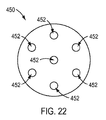
図19の例示的な実施態様に示すように、作動要素支持体440は、5つの管腔442,444,446を含む。しかしながら、作動要素支持体を含む、手術器具は、5つの5部材だけに限定されず、より多い又はより少ない数の管腔が器具において用いられてよい。例えば、作動要素支持体450が、図22の例示的な実施態様に示すように、7つの管腔452を含んでよい。加えて、作動要素支持体の管腔は、図22の例示的な実施態様におけるように、中央管腔の周りの管腔の単一のリング(a ring of lumens)として配置される必要はない。代わりに、支持体460の管腔462は、図23の例示的な実施態様に示すように、中心管腔の周りの複数の同心状のリングにおいて配置されてよい。
As shown in the exemplary embodiment of FIG. 19, the
図18の例示的な実施態様に関して上で議論したように、作動要素支持体は、一体成形構造を有してよい。例えば、支持体は、押し出した一体成形品であってよい。そのような押出品は、溝のない中実な実質的に連続的な外面を有してよい。しかしながら、作動要素支持体について他の構成及び構造が用いられてよい。例えば、作動要素支持体は、支持体の可撓性(フレキシビリティ)を強化する1つ又はそれよりも多くの材料弱化領域を含んでよい。図24を参照すると、作動要素支持体710の例示的な実施態様が示されており、作動要素724,726が支持体710を通じて延在している。支持体710がリストによって曲げられるときのような、支持体710の可撓性を強化するために、支持体710は、図24の例示的な実施態様に示すような、溝712のような、1つ又はそれよりも多くの材料弱化領域を含んでよい。例示的な実施態様によれば、支持体710は、図19の例示的な実施態様と同様に、支持体710を通じて形成される管腔を備える押出品として形成されよく、押出品に切り込まれた溝712を有して、溝712によって分離される椎骨部714をもたらしてよい。図24の線25−25に沿う断面図である図25に示すように、支持体710は、図19の例示的な実施態様と同様に、5つの管腔711,713,715,717,719を含んでよい。しかしながら、支持体710は、他の数の管腔を含んでよく、図22及び23の例示的な実施態様の管腔構成を含んでよい。例示的な実施態様によれば、支持体710は、溝に加えて他の弱化領域を含んでよい。例えば、支持体710は、支持体710に追加的な弱化領域を強化された可撓性をもたらすよう、椎骨部714に形成されてよい孔730を含んでよい。
As discussed above with respect to the exemplary embodiment of FIG. 18, the actuation element support may have a unitary construction. For example, the support may be an extruded monolith. Such an extrudate may have a solid substantially continuous outer surface without grooves. However, other configurations and structures for the actuating element support may be used. For example, the actuation element support may include one or more material weakened regions that enhance the support's flexibility. Referring to FIG. 24, an exemplary embodiment of an
例示的な実施態様によれば、作動要素は、図18、24及び25の一体成形構造以外の構成部品によって支持されてよく、捩れ経路に形作られてよい。図26を参照すると、例示的な実施態様に従って、複数の別個のリンク802乃至805によって形成される作動支持体800の分解図が示されている。リンク802乃至805は、作動要素(図示せず)のための1つ又はそれよりも多くの通路810,812を含んでよい。図26の例示的な実施態様に示すように、リンク802乃至805は、通路810,812を通じて進む作動要素に捻れを付与するよう、方向818において支持体800の長手軸816(即ち、中心線)について回転させられてよい。よって、リンク802乃至805の通路810,812は、リンク毎に中心線816に対して異なる角位置を有してよい。リンク802乃至805は、図10A乃至17の例示的な実施態様において議論した捻れの量のような、他の量の捻れを付与してよい。加えて、リンク802乃至805は、他の数の管腔を含んでよく、図22及び23の例示的な実施態様の管腔構成を含んでよい。
According to an exemplary embodiment, the actuation element may be supported by components other than the unitary construction of FIGS. 18, 24 and 25 and may be shaped into a torsional path. Referring to FIG. 26, an exploded view of a working
図18の例示的な実施態様に示すように、作動要素支持体410の管腔415乃至418は、1つの方向において支持体410の一端から他の端に捩れてよい。しかしながら、作動要素支持体は、そのような捩れ構成に限定されず、代わりに、1つよりも多くの方向において捩れる管腔を含んでよい。図27を参照すると、作動要素支持体470の例示的な実施態様が示されており、作動要素支持体470は、方向471において支持体470に沿って第1の方向476において捩れ、次に、方向478に沿って捩るよう逆転する、管腔472,474を含む。更に、捻れの量は、支持体の長さに沿って一定であってよく、或いは、支持体の長さに沿って増大し或いは減少することにより異なってよい。
As shown in the exemplary embodiment of FIG. 18, the lumens 415-418 of the
上で議論したように、作動要素支持体は、捩れ経路に沿って作動要素を案内するよう、並びに作動要素を支持して作動要素の座屈を最小にし或いは防止するよう、機能してよい。作動要素支持体と共に用いられてよい、作動要素の支持及びその座屈強度を強化する、他の構造が提供されてよい。図28を参照すると、作動要素500の非支持区画502の遠位端に剛性区画510を含む、作動要素500の例示的な実施態様が示されている。図28の部分504の拡大図である図29に示すように、作動要素500は、剛性区画510に延びるワイヤ又はケーブル506を含んでよい。ワイヤ又はケーブル506は、例えば、図18の例示的な実施態様の作動要素426,428のうちの1つであってよい。剛性区画510は、ワイヤ又はケーブル506の上に嵌められる剛性シリンダ512を含んでよい。剛性シリンダ512は、例えば、ステンレス鋼のような、鋼で作られてよい。剛性シリンダ512は、例えば、シリンダ512をワイヤ又はケーブル506にクリンプ留めすることを介して、ワイヤ又はケーブル506に接続されてよい。
As discussed above, the actuating element support may function to guide the actuating element along a torsional path and to support the actuating element to minimize or prevent buckling of the actuating element. Other structures may be provided that enhance the support of the actuation element and its buckling strength that may be used with the actuation element support. Referring to FIG. 28, an exemplary embodiment of an
例示的な実施態様によれば、ワイヤ又はケーブル506の非支持区画502は、被膜508を含んでよい。被膜を用いて、例えば、ワイヤ又はケーブル506に、ワイヤ又はケーブル506よりも低い摩擦係数を有する滑らかな表面をもたらしてよい。被膜508は、熱可塑性物質(thermoplastic)のような、ポリマで作られてよい。例示的な実施態様によれば、被膜508は、例えば、PTFE、エチレンテトラフルオロエチレン(ETFE)、シリコーン、又は当業者によく知られた他の被膜材料で作られてよい。例示的な実施態様によれば、被膜508は、図29に示すように、シリンダ512の厚さと実質的に同じ厚さである厚さを有してよい。
According to an exemplary embodiment, the
作動要素500に剛性区画510を設けることによって、作動要素500の座屈強度が強化されることがある。例えば、作動要素500が作動要素支持体530(例えば、図18の例示的な実施態様の作動要素支持体410)を通じて挿入されるとき、図30に例示的な実施態様に示すように、作動要素500は方向534に沿って押され、作動要素500の遠位端を作動要素支持体530の遠位端532を越えて延ばすことがある。作動要素500は剛性区画510を含むので、作動要素支持体530の遠位端532を越えて延びる作動要素500の部分は、強化された座屈強度を有することがある。例えば、作動要素500が方向534に押されるときに、図30に示すように、作動要素500の非支持部分は作動要素支持体530内に留まり、作動要素500の剛性区画510のみが作動要素530の遠位端を越えて延びるよう、手術器具が構成されてよい。
By providing the
例示的な実施態様によれば、図28に示すように、作動要素500の近位端も、剛性区画520を含んでよいが、他の例示的な実施態様は、作動要素の近位端に剛性区画を欠いてよい。近位端にある剛性区画520は、図29の例示的な実施態様の剛性区画510に従って構成されてよい。例示的な実施態様によれば、剛性区画520は、図30の例示的な実施態様と同様に、例えば、作動要素が押されるときに、作動要素支持体の近位端を越えて延びてよい。
According to an exemplary embodiment, as shown in FIG. 28, the proximal end of the
作動要素を支持するために用いられてよい他の構造は、フレキシブルシャフトである。図31を参照すると、フレキシブルシャフト600の例示的な実施態様が示されており、フレキシブルシャフト600は、圧縮部材610と、張力部材614とを含む。フレキシブルシャフト600を用いて作動要素を支持してよく、フレキシブルシャフト600は、図30の例示的な実施態様と同様に、作動要素支持体の少なくとも部分を通じて延びる。圧縮部材610は、作動要素が通じて進むための中央管腔612を有してよい。圧縮部材610は、例えば、圧縮力がフレキシブルシャフト600の長手軸616に沿って加えられるときに、互いに圧縮し合う巻線を含むバネであってよい。張力部材614は、軸616に沿って加えられる引張力又はフレキシブルシャフト600に加えられる曲げ力に抗するよう、圧縮部材610の外部にあるような、圧縮部材610に取り付けられるワイヤ又はケーブルであってよい。換言すれば、フレキシブルシャフト600は、圧縮部材610が存在しないならば張力部材614を圧縮し得る圧縮に抗する圧縮部材610と、さもなければ圧縮部材610を引き離し得る張力及び曲げに抗する張力部材614との組み合わせであってよい。
Another structure that may be used to support the actuating element is a flexible shaft. Referring to FIG. 31, an exemplary embodiment of a
例示的な実施態様によれば、作動要素支持体は、複数のフレキシブルシャフト層を含んでよい。例えば、作動要素支持体は、互いに重なり合う図31の例示的な実施態様のフレキシブルシャフト600の多数の層を提供することによってのように、互いに層状に重なり合う多数のフレキシブルシャフトを含んでよい。フレキシブルシャフトの様々な層は、互いに同軸であってよい。例えば、図32の例示的な実施態様に示すように、作動要素支持体1000が、互いに同軸である、第1のフレキシブルチューブ1002及び第2のフレキシブルチューブ1004を含んでよく、1つ又はそれよりも多くの作動要素1010が、支持体1000を通じて延びる。2つだけの同軸のチューブ1002,1004が図36の例示的な実施態様に描写されているが、支持体1000は、例えば、3つ、4つ、又はそれよりも多くのフレキシブル同軸チューブのような、他の数の同軸のチューブを含んでよい。フレキシブルチューブ1002,1004は、例えば、例示的な実施態様に従って、チューブ1002,1004が撓むのを可能にする弱化領域をもたらすよう、チューブ1002,1004に溝又はスリットを切ることを介した、チューブ1002,1004からの材料の除去の故に、フレキシブルであってよい。例示的な実施態様によれば、チューブ1002,1004は、引張荷重にとって有用である、巻回フィラメント備える、圧縮荷重にとって有用である、中実な巻回バネであってよい。
According to an exemplary embodiment, the actuation element support may include a plurality of flexible shaft layers. For example, the actuating element support may include multiple flexible shafts layered on top of each other, such as by providing multiple layers of
他の例示的な実施態様によれば、作動部材を支持するフレキシブルシャフトは、互いに接続される巻回フィラメントの多数の層を含んでよい。例えば、図31の例示的な実施態様の圧縮部材610を含むことの代わりに、フレキシブルシャフトは、張力部材614を互いに編むことによってのように、互いに接続される、複数の張力部材614を含んでよい。例示的な実施態様によれば、作動要素支持体は、例えば、チューブの可撓性を強化するために、1つ又はそれよりも多くの場所においてチューブを切ることを介してのように、部分が取り除かれたチューブによって形成される、フレキシブルシャフトであってよい。チューブは、例えば、ステンレス鋼、熱可塑性物質、当業者によく知られている他の材料で作られてよい。
According to another exemplary embodiment, the flexible shaft supporting the actuating member may include multiple layers of wound filaments connected to each other. For example, instead of including the compression member 610 of the exemplary embodiment of FIG. 31, the flexible shaft includes a plurality of
ここにおいて記載した例示的な実施態様及び方法は、遠隔操作手術システムのための手術器具と共に利用されるものとして記載されている。しかしながら、ここにおいて記載する例示的な実施態様及び方法は、腹腔鏡器具及び他の手持ち器具のような、他の手術デバイスと共に用いられてよい。更に、例示的な実施態様及び方法は、リスト又は関節構造に取り付けられる物体を遠隔に位置付けるような、遠隔作動可能なリスト又は多数の関節構造を用いる他の用途において利用されてよい。 The exemplary embodiments and methods described herein have been described for use with surgical instruments for a remotely operated surgical system. However, the exemplary embodiments and methods described herein may be used with other surgical devices, such as laparoscopic instruments and other hand-held instruments. Further, the exemplary embodiments and methods may be utilized in remotely actuated wrists or other applications using multiple articulation structures, such as remotely locating objects attached to the wrist or articulation structure.
手術器具が曲げられるときにその長さを実質的に維持するように構成される作動要素を備える手術器具を提供することによって、作動要素はその長さの変化からの実質的な干渉を伴わずに器具の構成部品を作動させることが可能にされてよく、手術器具は製造が比較的容易な簡略化された設計を有することがある。 By providing a surgical instrument with an actuating element configured to substantially maintain its length when the surgical instrument is bent, the actuating element has no substantial interference from changes in its length The surgical instrument may have a simplified design that is relatively easy to manufacture.
更なる変更及び代替的な実施態様が、ここにおける開示に鑑みて当業者に明らかであろう。例えば、システム及び方法は、動作の明瞭性のために図面及び記述から省略された追加的な構成部品又はステップを含んでよい。従って、この記述は、例示的であるに過ぎないものとして解釈されるべきであり、本教示を実施する一般的な方法を当業者に教示する目的のためである。ここにおいて示し且つ記載する様々な実施態様は例示的であると取られるべきことが理解されるべきである。ここにおける記述の利益を有した後に当業者に全て明らかであるように、要素及び材料、並びにそれらの要素及び材料の配置は、ここに例示し且つ記載するものと置換されてよく、部品及びプロセスは逆転させられてよく、本教示の特定の構成は独立して利用されてよい。本教示及び後続の請求項の精神及び範囲から逸脱せずに、ここにおいて記載する要素における変更が行われてよい。 Further modifications and alternative embodiments will be apparent to those skilled in the art in light of the present disclosure. For example, the systems and methods may include additional components or steps that have been omitted from the drawings and description for clarity of operation. Accordingly, this description is to be construed as illustrative only and is for the purpose of teaching those skilled in the art how to practice the teachings. It should be understood that the various embodiments shown and described herein are to be taken as illustrative. As will be apparent to one of ordinary skill in the art after having the benefit of the description herein, the elements and materials, and the arrangement of those elements and materials, may be substituted for those illustrated and described herein, and in parts and processes. May be reversed, and certain configurations of the present teachings may be utilized independently. Changes may be made in the elements described herein without departing from the spirit and scope of the present teachings and the following claims.
ここにおいて示す特定の実施例及び実施態様は非限定的であること、並びに、構造、寸法、材料、及び方法論に対する変更が、本教示の範囲から逸脱せずに行われてよいことが、理解されるべきである。 It is understood that the specific examples and embodiments described herein are non-limiting, and that changes to structure, dimensions, materials, and methodologies may be made without departing from the scope of the present teachings. Should be.
本開示に従った他の実施態様が、本明細書の考察及びここに開示する発明の実施から当業者に明らかであろう。明細書及び実施例は例示的にのみ考えられるべきであり、真正な範囲及び精神は後続の請求項によって示されることが意図されている。 Other embodiments in accordance with the present disclosure will be apparent to one skilled in the art from consideration of the specification and practice of the invention disclosed herein. It is intended that the specification and examples be considered as exemplary only, with a true scope and spirit being indicated by the following claims.
Claims (20)
該シャフトの第1の端部分に連結されるリストであって、第1の関節と、第2の関節とを含み、前記第1の関節は、第1の方向に延びる第1の曲げ軸を有し、前記第2の関節は、前記第1の方向とは異なる第2の方向に延びる第2の曲げ軸を有する、リストと、
該リストに連結されるエンドエフェクタと、
前記シャフト及び前記リストに沿って延びる、作動要素とを含み、
該作動要素は、前記リストの少なくとも部分に沿う捩れ経路に従い、該捩れ経路は、前記リストの全長に沿って360度未満の角度的な広がりを有し、
前記作動要素は、前記リストの前記第1の関節と前記リストの前記第2の関節との組み合わせに亘って実質的に長さを維持し、
前記作動要素は、前記第1の関節又は前記第2の関節の各々に亘って長さを維持しない、
手術器具。 Shaft and
A wrist coupled to a first end portion of the shaft, the wrist including a first joint and a second joint, wherein the first joint has a first bending axis extending in a first direction. A wrist, wherein the second joint has a second bending axis extending in a second direction different from the first direction;
An end effector coupled to the list;
An actuating element extending along the shaft and the wrist;
The actuating element according to the routing twisted along at least part of said list,該捩Re path, have a angular spread of less than 360 degrees along the length of the list,
The actuation element maintains a substantial length over a combination of the first joint of the wrist and the second joint of the wrist;
The actuation element does not maintain a length across each of the first joint or the second joint ;
Surgical instruments.
該シャフトの第1の端部分に連結されるリストであって、第1の関節と、第2の関節とを含み、前記第1の関節は、第1の方向に延びる第1の曲げ軸を有し、前記第2の関節は、前記第1の方向とは異なる第2の方向に延びる第2の曲げ軸を有する、リストと、
該リストに連結されるエンドエフェクタと、
前記シャフト及び前記リストに沿って延びる、作動要素とを含み、
該作動要素は、前記リストの少なくとも部分に沿う捩れ経路に従い、該捩れ経路は、前記リストの全長に沿って360度未満の角度的な広がりを有し、
前記リストは、第3の関節を更に含み、
前記作動要素は、前記リストの前記第1の関節に亘って実質的に長さを維持し、
前記作動要素は、前記リストの前記第2の関節と前記リストの第3の関節との組み合わせに亘って実質的に長さを維持し、
前記作動要素は、個々の第2の関節又は個々の第3の関節に亘って長さを維持しない、
手術器具。 Shaft and
A wrist coupled to a first end portion of the shaft, the wrist including a first joint and a second joint, wherein the first joint has a first bending axis extending in a first direction. A wrist, wherein the second joint has a second bending axis extending in a second direction different from the first direction;
An end effector coupled to the list;
An actuating element extending along the shaft and the wrist;
The actuating element according to the routing twisted along at least part of said list,該捩Re path, have a angular spread of less than 360 degrees along the length of the list,
The list further includes a third joint;
The actuation element maintains a length substantially across the first joint of the wrist;
The actuating element maintains a substantial length over the combination of the second joint of the wrist and the third joint of the wrist ;
The actuating element does not maintain a length across an individual second joint or an individual third joint ;
Surgery equipment.
該シャフトの第1の端部分に連結されるリストであって、第1の関節と、第2の関節とを含み、前記第1の関節は、第1の方向に延びる第1の曲げ軸を有し、前記第2の関節は、前記第1の方向とは異なる第2の方向に延びる第2の曲げ軸を有する、リストと、
該リストに連結されるエンドエフェクタと、
前記シャフト及び前記リストに沿って延びる、作動要素とを含み、
該作動要素は、前記リストの少なくとも部分に沿う捩れ経路に従い、該捩れ経路は、前記リストの全長に沿って360度未満の角度的な広がりを有し、
前記リストは、第3の関節を更に含み、
前記作動要素は、前記第1の関節に沿う捩れ経路に従うことなく、前記第1の関節に亘って実質的に長さを維持し、
前記作動要素は、前記第2の関節と前記第3の関節との組み合わせに亘って長さを維持し、
前記作動要素は、個々の第2の関節又は個々の第3の関節に亘って長さを維持しない、
手術器具。 Shaft and
A wrist coupled to a first end portion of the shaft, the wrist including a first joint and a second joint, wherein the first joint has a first bending axis extending in a first direction. A wrist, wherein the second joint has a second bending axis extending in a second direction different from the first direction;
An end effector coupled to the list;
An actuating element extending along the shaft and the wrist;
The actuating element according to the routing twisted along at least part of said list,該捩Re path, have a angular spread of less than 360 degrees along the length of the list,
The list further includes a third joint;
The actuating element maintains a substantial length across the first joint without following a torsional path along the first joint;
The actuation element maintains a length across the combination of the second joint and the third joint;
The actuating element does not maintain a length across an individual second joint or an individual third joint ;
Surgery equipment.
前記第2の関節及び前記第3の関節に亘る前記捩れ経路は、約180度の角度的な広がりを有する、
請求項3に記載の手術器具。 The actuating element follows the torsional path across the second joint and the third joint;
The torsional path across the second joint and the third joint has an angular extent of about 180 degrees;
The surgical instrument according to claim 3 .
該シャフトの第1の端部分に連結されるリストであって、第1の関節と、第2の関節とを含み、前記第1の関節は、第1の方向に延びる第1の曲げ軸を有し、前記第2の関節は、前記第1の方向とは異なる第2の方向に延びる第2の曲げ軸を有する、リストと、
該リストに連結されるエンドエフェクタと、
前記シャフト及び前記リストに沿って延びる、作動要素とを含み、
該作動要素は、前記リストの少なくとも部分に沿う捩れ経路に従い、該捩れ経路は、前記リストの全長に沿って360度未満の角度的な広がりを有し、
前記リストは、第3の関節と、第4の関節とを更に含み、
前記第3の関節は、前記第2の関節に隣接し、前記第2の方向に沿う曲げ軸を有し、
前記第4の関節は、前記第3の関節に隣接し、前記第1の方向に沿う曲げ軸を有する、
手術器具。 Shaft and
A wrist coupled to a first end portion of the shaft, the wrist including a first joint and a second joint, wherein the first joint has a first bending axis extending in a first direction. A wrist, wherein the second joint has a second bending axis extending in a second direction different from the first direction;
An end effector coupled to the list;
An actuating element extending along the shaft and the wrist;
The actuating element according to the routing twisted along at least part of said list,該捩Re path, have a angular spread of less than 360 degrees along the length of the list,
The list further includes a third joint and a fourth joint;
The third joint is adjacent to the second joint and has a bending axis along the second direction;
The fourth joint is adjacent to the third joint and has a bending axis along the first direction .
Surgery equipment.
該シャフトの第1の端部分に連結されるリストであって、第1の関節と、第2の関節とを含み、前記第1の関節は、第1の方向に延びる第1の曲げ軸を有し、前記第2の関節は、前記第1の方向とは異なる第2の方向に延びる第2の曲げ軸を有する、リストと、
該リストに連結されるエンドエフェクタと、
前記シャフト及び前記リストに沿って延びる、作動要素とを含み、
該作動要素は、前記リストの少なくとも部分に沿う捩れ経路に従い、該捩れ経路は、前記リストの全長に沿って360度未満の角度的な広がりを有し、
前記捩れ経路が捩れる軸が、前記リストの長手中心線から径方向に偏心させられる、
手術器具。 Shaft and
A wrist coupled to a first end portion of the shaft, the wrist including a first joint and a second joint, wherein the first joint has a first bending axis extending in a first direction. A wrist, wherein the second joint has a second bending axis extending in a second direction different from the first direction;
An end effector coupled to the list;
An actuating element extending along the shaft and the wrist;
The actuating element according to the routing twisted along at least part of said list,該捩Re path, have a angular spread of less than 360 degrees along the length of the list,
The axis from which the torsion path is twisted is radially eccentric from the longitudinal centerline of the wrist ;
Surgery equipment.
該伝動機構は、前記作動要素に沿って駆動力を伝える、
請求項1、2、3、6又は7に記載の手術器具。 A transmission mechanism coupled to a second end portion of the shaft opposite the first end portion of the shaft;
The transmission mechanism transmits a driving force along the operating element;
The surgical instrument according to claim 1 , 2, 3, 6, or 7 .
前記伝動機構は、前記作動要素に沿って前記駆動力を伝えて、前記エンドエフェクタを作動させる、
請求項8に記載の手術器具。 The actuation element extends to the end effector;
The transmission mechanism transmits the driving force along the operation element to operate the end effector,
The surgical instrument according to claim 8 .
前記作動要素は、前記作動要素支持構造の前記管腔を通じて延びる、
請求項1、2、3、6、7、8、9又は10に記載の手術器具。 An actuation element support structure including at least one lumen defining the torsion path;
The actuation element extends through the lumen of the actuation element support structure;
The surgical instrument according to claim 1 , 2, 3, 6, 7, 8, 9 or 10 .
前記別個のリンクの各リンクは、前記作動要素を受け入れる通路を含み、
前記別個のリンクの前記通路は、前記リストの長手中心線について異なる角位置に位置付けられる、
請求項11に記載の手術器具。 The actuation element support structure includes a separate link;
Each of said separate links includes a passage for receiving said actuating element;
The passages of the separate links are located at different angular positions about a longitudinal centerline of the wrist;
The surgical instrument according to claim 11 .
該第2の作動要素は、前記リストの少なくとも部分に沿う第2の捩れ経路に従い、
前記作動要素の前記捩れ経路及び前記第2の作動要素の前記第2の捩れ経路は、実質的に互いに平行である、
請求項1、2、3、6、7、8、9又は10に記載の手術器具。 A second actuation element extending along the shaft and the wrist;
The second actuation element follows a second torsion path along at least a portion of the wrist,
The torsion path of the actuation element and the second torsion path of the second actuation element are substantially parallel to each other;
The surgical instrument according to claim 1 , 2, 3, 6, 7, 8, 9 or 10 .
Applications Claiming Priority (3)
| Application Number | Priority Date | Filing Date | Title |
|---|---|---|---|
| US201461943084P | 2014-02-21 | 2014-02-21 | |
| US61/943,084 | 2014-02-21 | ||
| PCT/US2015/016854 WO2015127231A1 (en) | 2014-02-21 | 2015-02-20 | Mechanical joints, and related systems and methods |
Related Child Applications (1)
| Application Number | Title | Priority Date | Filing Date |
|---|---|---|---|
| JP2019213773A Division JP7153630B2 (en) | 2014-02-21 | 2019-11-27 | Mechanical joints and related systems and methods |
Publications (3)
| Publication Number | Publication Date |
|---|---|
| JP2017509391A JP2017509391A (en) | 2017-04-06 |
| JP2017509391A5 JP2017509391A5 (en) | 2018-03-29 |
| JP6664331B2 true JP6664331B2 (en) | 2020-03-13 |
Family
ID=53879031
Family Applications (4)
| Application Number | Title | Priority Date | Filing Date |
|---|---|---|---|
| JP2016553459A Active JP6664331B2 (en) | 2014-02-21 | 2015-02-20 | Mechanical joints and related systems and methods |
| JP2019213773A Active JP7153630B2 (en) | 2014-02-21 | 2019-11-27 | Mechanical joints and related systems and methods |
| JP2021134996A Pending JP2021191424A (en) | 2014-02-21 | 2021-08-20 | Mechanical joints, and related systems and methods |
| JP2023085201A Pending JP2023111922A (en) | 2014-02-21 | 2023-05-24 | Mechanical joints, and related systems and methods |
Family Applications After (3)
| Application Number | Title | Priority Date | Filing Date |
|---|---|---|---|
| JP2019213773A Active JP7153630B2 (en) | 2014-02-21 | 2019-11-27 | Mechanical joints and related systems and methods |
| JP2021134996A Pending JP2021191424A (en) | 2014-02-21 | 2021-08-20 | Mechanical joints, and related systems and methods |
| JP2023085201A Pending JP2023111922A (en) | 2014-02-21 | 2023-05-24 | Mechanical joints, and related systems and methods |
Country Status (6)
| Country | Link |
|---|---|
| US (2) | US10524870B2 (en) |
| EP (1) | EP3107479A4 (en) |
| JP (4) | JP6664331B2 (en) |
| KR (1) | KR102410823B1 (en) |
| CN (2) | CN111938820A (en) |
| WO (1) | WO2015127231A1 (en) |
Families Citing this family (224)
| Publication number | Priority date | Publication date | Assignee | Title |
|---|---|---|---|---|
| US8414505B1 (en) | 2001-02-15 | 2013-04-09 | Hansen Medical, Inc. | Catheter driver system |
| US9060770B2 (en) | 2003-05-20 | 2015-06-23 | Ethicon Endo-Surgery, Inc. | Robotically-driven surgical instrument with E-beam driver |
| US20070084897A1 (en) | 2003-05-20 | 2007-04-19 | Shelton Frederick E Iv | Articulating surgical stapling instrument incorporating a two-piece e-beam firing mechanism |
| US11896225B2 (en) | 2004-07-28 | 2024-02-13 | Cilag Gmbh International | Staple cartridge comprising a pan |
| US7669746B2 (en) | 2005-08-31 | 2010-03-02 | Ethicon Endo-Surgery, Inc. | Staple cartridges for forming staples having differing formed staple heights |
| US10159482B2 (en) | 2005-08-31 | 2018-12-25 | Ethicon Llc | Fastener cartridge assembly comprising a fixed anvil and different staple heights |
| US11246590B2 (en) | 2005-08-31 | 2022-02-15 | Cilag Gmbh International | Staple cartridge including staple drivers having different unfired heights |
| US20070106317A1 (en) | 2005-11-09 | 2007-05-10 | Shelton Frederick E Iv | Hydraulically and electrically actuated articulation joints for surgical instruments |
| US11793518B2 (en) | 2006-01-31 | 2023-10-24 | Cilag Gmbh International | Powered surgical instruments with firing system lockout arrangements |
| US8186555B2 (en) | 2006-01-31 | 2012-05-29 | Ethicon Endo-Surgery, Inc. | Motor-driven surgical cutting and fastening instrument with mechanical closure system |
| US8820603B2 (en) | 2006-01-31 | 2014-09-02 | Ethicon Endo-Surgery, Inc. | Accessing data stored in a memory of a surgical instrument |
| US7845537B2 (en) | 2006-01-31 | 2010-12-07 | Ethicon Endo-Surgery, Inc. | Surgical instrument having recording capabilities |
| US20120292367A1 (en) | 2006-01-31 | 2012-11-22 | Ethicon Endo-Surgery, Inc. | Robotically-controlled end effector |
| US20110290856A1 (en) | 2006-01-31 | 2011-12-01 | Ethicon Endo-Surgery, Inc. | Robotically-controlled surgical instrument with force-feedback capabilities |
| US8708213B2 (en) | 2006-01-31 | 2014-04-29 | Ethicon Endo-Surgery, Inc. | Surgical instrument having a feedback system |
| US10568652B2 (en) | 2006-09-29 | 2020-02-25 | Ethicon Llc | Surgical staples having attached drivers of different heights and stapling instruments for deploying the same |
| US8684253B2 (en) | 2007-01-10 | 2014-04-01 | Ethicon Endo-Surgery, Inc. | Surgical instrument with wireless communication between a control unit of a robotic system and remote sensor |
| US8540128B2 (en) | 2007-01-11 | 2013-09-24 | Ethicon Endo-Surgery, Inc. | Surgical stapling device with a curved end effector |
| US8931682B2 (en) | 2007-06-04 | 2015-01-13 | Ethicon Endo-Surgery, Inc. | Robotically-controlled shaft based rotary drive systems for surgical instruments |
| US11564682B2 (en) | 2007-06-04 | 2023-01-31 | Cilag Gmbh International | Surgical stapler device |
| US11849941B2 (en) | 2007-06-29 | 2023-12-26 | Cilag Gmbh International | Staple cartridge having staple cavities extending at a transverse angle relative to a longitudinal cartridge axis |
| US8636736B2 (en) | 2008-02-14 | 2014-01-28 | Ethicon Endo-Surgery, Inc. | Motorized surgical cutting and fastening instrument |
| RU2493788C2 (en) | 2008-02-14 | 2013-09-27 | Этикон Эндо-Серджери, Инк. | Surgical cutting and fixing instrument, which has radio-frequency electrodes |
| US9204923B2 (en) | 2008-07-16 | 2015-12-08 | Intuitive Surgical Operations, Inc. | Medical instrument electronically energized using drive cables |
| US9005230B2 (en) | 2008-09-23 | 2015-04-14 | Ethicon Endo-Surgery, Inc. | Motorized surgical instrument |
| US11648005B2 (en) | 2008-09-23 | 2023-05-16 | Cilag Gmbh International | Robotically-controlled motorized surgical instrument with an end effector |
| US9386983B2 (en) | 2008-09-23 | 2016-07-12 | Ethicon Endo-Surgery, Llc | Robotically-controlled motorized surgical instrument |
| US8210411B2 (en) | 2008-09-23 | 2012-07-03 | Ethicon Endo-Surgery, Inc. | Motor-driven surgical cutting instrument |
| US8608045B2 (en) | 2008-10-10 | 2013-12-17 | Ethicon Endo-Sugery, Inc. | Powered surgical cutting and stapling apparatus with manually retractable firing system |
| US9629814B2 (en) | 2010-09-30 | 2017-04-25 | Ethicon Endo-Surgery, Llc | Tissue thickness compensator configured to redistribute compressive forces |
| US9861361B2 (en) | 2010-09-30 | 2018-01-09 | Ethicon Llc | Releasable tissue thickness compensator and fastener cartridge having the same |
| US10945731B2 (en) | 2010-09-30 | 2021-03-16 | Ethicon Llc | Tissue thickness compensator comprising controlled release and expansion |
| US9295464B2 (en) | 2010-09-30 | 2016-03-29 | Ethicon Endo-Surgery, Inc. | Surgical stapler anvil comprising a plurality of forming pockets |
| US11812965B2 (en) | 2010-09-30 | 2023-11-14 | Cilag Gmbh International | Layer of material for a surgical end effector |
| US9320523B2 (en) | 2012-03-28 | 2016-04-26 | Ethicon Endo-Surgery, Llc | Tissue thickness compensator comprising tissue ingrowth features |
| US11925354B2 (en) | 2010-09-30 | 2024-03-12 | Cilag Gmbh International | Staple cartridge comprising staples positioned within a compressible portion thereof |
| RU2606493C2 (en) | 2011-04-29 | 2017-01-10 | Этикон Эндо-Серджери, Инк. | Staple cartridge, containing staples, located inside its compressible part |
| US9161771B2 (en) | 2011-05-13 | 2015-10-20 | Intuitive Surgical Operations Inc. | Medical instrument with snake wrist structure |
| CN104321024B (en) | 2012-03-28 | 2017-05-24 | 伊西康内外科公司 | Tissue thickness compensator comprising a plurality of layers |
| CN104334098B (en) | 2012-03-28 | 2017-03-22 | 伊西康内外科公司 | Tissue thickness compensator comprising capsules defining a low pressure environment |
| US20130317519A1 (en) | 2012-05-25 | 2013-11-28 | Hansen Medical, Inc. | Low friction instrument driver interface for robotic systems |
| US9101358B2 (en) | 2012-06-15 | 2015-08-11 | Ethicon Endo-Surgery, Inc. | Articulatable surgical instrument comprising a firing drive |
| US20140001231A1 (en) | 2012-06-28 | 2014-01-02 | Ethicon Endo-Surgery, Inc. | Firing system lockout arrangements for surgical instruments |
| US9289256B2 (en) | 2012-06-28 | 2016-03-22 | Ethicon Endo-Surgery, Llc | Surgical end effectors having angled tissue-contacting surfaces |
| RU2672520C2 (en) | 2013-03-01 | 2018-11-15 | Этикон Эндо-Серджери, Инк. | Hingedly turnable surgical instruments with conducting ways for signal transfer |
| US9668814B2 (en) | 2013-03-07 | 2017-06-06 | Hansen Medical, Inc. | Infinitely rotatable tool with finite rotating drive shafts |
| US9498601B2 (en) | 2013-03-14 | 2016-11-22 | Hansen Medical, Inc. | Catheter tension sensing |
| US20140277334A1 (en) | 2013-03-14 | 2014-09-18 | Hansen Medical, Inc. | Active drives for robotic catheter manipulators |
| US9326822B2 (en) | 2013-03-14 | 2016-05-03 | Hansen Medical, Inc. | Active drives for robotic catheter manipulators |
| US9173713B2 (en) | 2013-03-14 | 2015-11-03 | Hansen Medical, Inc. | Torque-based catheter articulation |
| US11213363B2 (en) | 2013-03-14 | 2022-01-04 | Auris Health, Inc. | Catheter tension sensing |
| US9408669B2 (en) | 2013-03-15 | 2016-08-09 | Hansen Medical, Inc. | Active drive mechanism with finite range of motion |
| US20140276936A1 (en) | 2013-03-15 | 2014-09-18 | Hansen Medical, Inc. | Active drive mechanism for simultaneous rotation and translation |
| US9452018B2 (en) | 2013-03-15 | 2016-09-27 | Hansen Medical, Inc. | Rotational support for an elongate member |
| US20140276647A1 (en) | 2013-03-15 | 2014-09-18 | Hansen Medical, Inc. | Vascular remote catheter manipulator |
| BR112015026109B1 (en) | 2013-04-16 | 2022-02-22 | Ethicon Endo-Surgery, Inc | surgical instrument |
| US9510828B2 (en) | 2013-08-23 | 2016-12-06 | Ethicon Endo-Surgery, Llc | Conductor arrangements for electrically powered surgical instruments with rotatable end effectors |
| US9763741B2 (en) | 2013-10-24 | 2017-09-19 | Auris Surgical Robotics, Inc. | System for robotic-assisted endolumenal surgery and related methods |
| EP3834752B1 (en) | 2013-12-11 | 2024-03-13 | Covidien LP | Wrist and jaw assemblies for robotic surgical systems |
| CN113729963A (en) | 2014-02-21 | 2021-12-03 | 直观外科手术操作公司 | Articulatable members with constrained motion and related apparatus and methods |
| KR102410823B1 (en) | 2014-02-21 | 2022-06-21 | 인튜어티브 서지컬 오퍼레이션즈 인코포레이티드 | Mechanical joints, and related systems and methods |
| CN111616804B (en) | 2014-03-17 | 2024-04-09 | 直观外科手术操作公司 | Surgical drape and system including a surgical drape and an attached sensor |
| US10441372B2 (en) | 2014-03-17 | 2019-10-15 | Intuitive Surgical Operations, Inc. | Manipulator arm having connection interface, and related devices and systems |
| US10456208B2 (en) | 2014-03-17 | 2019-10-29 | Intuitive Surgical Operations, Inc. | Surgical cannula mounts and related systems and methods |
| KR102397300B1 (en) | 2014-03-17 | 2022-05-13 | 인튜어티브 서지컬 오퍼레이션즈 인코포레이티드 | Surgical cannulas and related systems and methods of identifying surgical cannulas |
| US10285763B2 (en) | 2014-04-02 | 2019-05-14 | Intuitive Surgical Operations, Inc. | Actuation element guide with twisting channels |
| US20150297223A1 (en) | 2014-04-16 | 2015-10-22 | Ethicon Endo-Surgery, Inc. | Fastener cartridges including extensions having different configurations |
| CN106456176B (en) | 2014-04-16 | 2019-06-28 | 伊西康内外科有限责任公司 | Fastener cartridge including the extension with various configuration |
| BR112016023807B1 (en) | 2014-04-16 | 2022-07-12 | Ethicon Endo-Surgery, Llc | CARTRIDGE SET OF FASTENERS FOR USE WITH A SURGICAL INSTRUMENT |
| US10046140B2 (en) | 2014-04-21 | 2018-08-14 | Hansen Medical, Inc. | Devices, systems, and methods for controlling active drive systems |
| US10569052B2 (en) | 2014-05-15 | 2020-02-25 | Auris Health, Inc. | Anti-buckling mechanisms for catheters |
| US9561083B2 (en) | 2014-07-01 | 2017-02-07 | Auris Surgical Robotics, Inc. | Articulating flexible endoscopic tool with roll capabilities |
| BR112017004361B1 (en) | 2014-09-05 | 2023-04-11 | Ethicon Llc | ELECTRONIC SYSTEM FOR A SURGICAL INSTRUMENT |
| US9788836B2 (en) | 2014-09-05 | 2017-10-17 | Ethicon Llc | Multiple motor control for powered medical device |
| US11357483B2 (en) | 2014-09-26 | 2022-06-14 | Intuitive Surgical Operations, Inc. | Surgical instrument with flexible shaft and actuation element guide |
| US9924944B2 (en) | 2014-10-16 | 2018-03-27 | Ethicon Llc | Staple cartridge comprising an adjunct material |
| US10517594B2 (en) | 2014-10-29 | 2019-12-31 | Ethicon Llc | Cartridge assemblies for surgical staplers |
| US10004501B2 (en) | 2014-12-18 | 2018-06-26 | Ethicon Llc | Surgical instruments with improved closure arrangements |
| US10085748B2 (en) | 2014-12-18 | 2018-10-02 | Ethicon Llc | Locking arrangements for detachable shaft assemblies with articulatable surgical end effectors |
| BR112017012996B1 (en) | 2014-12-18 | 2022-11-08 | Ethicon Llc | SURGICAL INSTRUMENT WITH AN ANvil WHICH IS SELECTIVELY MOVABLE ABOUT AN IMMOVABLE GEOMETRIC AXIS DIFFERENT FROM A STAPLE CARTRIDGE |
| JP6084342B2 (en) * | 2015-02-03 | 2017-02-22 | オリンパス株式会社 | Medical manipulator system and control method thereof |
| JP6718463B2 (en) | 2015-02-19 | 2020-07-08 | コヴィディエン リミテッド パートナーシップ | Method of repositioning an input device for a robotic surgical system |
| US11154301B2 (en) | 2015-02-27 | 2021-10-26 | Cilag Gmbh International | Modular stapling assembly |
| US10441279B2 (en) | 2015-03-06 | 2019-10-15 | Ethicon Llc | Multiple level thresholds to modify operation of powered surgical instruments |
| JP2020121162A (en) | 2015-03-06 | 2020-08-13 | エシコン エルエルシーEthicon LLC | Time dependent evaluation of sensor data to determine stability element, creep element and viscoelastic element of measurement |
| CN107405172B (en) | 2015-03-10 | 2021-04-13 | 柯惠Lp公司 | Measuring health of connector components of a robotic surgical system |
| US10213201B2 (en) | 2015-03-31 | 2019-02-26 | Ethicon Llc | Stapling end effector configured to compensate for an uneven gap between a first jaw and a second jaw |
| JP6719487B2 (en) | 2015-06-23 | 2020-07-08 | コヴィディエン リミテッド パートナーシップ | Robotic surgery assembly |
| WO2017044884A1 (en) | 2015-09-09 | 2017-03-16 | Auris Surgical Robotics, Inc. | Instrument device manipulator for a surgical robotics system |
| US10105139B2 (en) | 2015-09-23 | 2018-10-23 | Ethicon Llc | Surgical stapler having downstream current-based motor control |
| CN108024835B (en) | 2015-09-25 | 2021-08-31 | 柯惠Lp公司 | Robotic surgical assembly and instrument drive connector therefor |
| US11890015B2 (en) | 2015-09-30 | 2024-02-06 | Cilag Gmbh International | Compressible adjunct with crossing spacer fibers |
| US20170086829A1 (en) | 2015-09-30 | 2017-03-30 | Ethicon Endo-Surgery, Llc | Compressible adjunct with intermediate supporting structures |
| US9955986B2 (en) | 2015-10-30 | 2018-05-01 | Auris Surgical Robotics, Inc. | Basket apparatus |
| US10231793B2 (en) | 2015-10-30 | 2019-03-19 | Auris Health, Inc. | Object removal through a percutaneous suction tube |
| US9949749B2 (en) | 2015-10-30 | 2018-04-24 | Auris Surgical Robotics, Inc. | Object capture with a basket |
| EP3376988B1 (en) | 2015-11-19 | 2023-08-23 | Covidien LP | Optical force sensor for robotic surgical system |
| US10292704B2 (en) | 2015-12-30 | 2019-05-21 | Ethicon Llc | Mechanisms for compensating for battery pack failure in powered surgical instruments |
| US11213293B2 (en) | 2016-02-09 | 2022-01-04 | Cilag Gmbh International | Articulatable surgical instruments with single articulation link arrangements |
| US10448948B2 (en) | 2016-02-12 | 2019-10-22 | Ethicon Llc | Mechanisms for compensating for drivetrain failure in powered surgical instruments |
| EP3422990A4 (en) * | 2016-03-04 | 2019-11-13 | Covidien LP | Inverse kinematic control systems for robotic surgical system |
| WO2017173524A1 (en) | 2016-04-07 | 2017-10-12 | Titan Medical Inc. | Camera positioning method and apparatus for capturing images during a medical procedure |
| US10828028B2 (en) | 2016-04-15 | 2020-11-10 | Ethicon Llc | Surgical instrument with multiple program responses during a firing motion |
| US10357247B2 (en) | 2016-04-15 | 2019-07-23 | Ethicon Llc | Surgical instrument with multiple program responses during a firing motion |
| US20170296173A1 (en) | 2016-04-18 | 2017-10-19 | Ethicon Endo-Surgery, Llc | Method for operating a surgical instrument |
| US10454347B2 (en) | 2016-04-29 | 2019-10-22 | Auris Health, Inc. | Compact height torque sensing articulation axis assembly |
| EP3463162A4 (en) | 2016-06-03 | 2020-06-24 | Covidien LP | Systems, methods, and computer-readable program products for controlling a robotically delivered manipulator |
| US11446099B2 (en) | 2016-06-03 | 2022-09-20 | Covidien Lp | Control arm for robotic surgical systems |
| WO2018013300A1 (en) | 2016-07-14 | 2018-01-18 | Intuitive Surgical Operations, Inc. | Mechanism for managing and retaining a surgical drape |
| US11241559B2 (en) | 2016-08-29 | 2022-02-08 | Auris Health, Inc. | Active drive for guidewire manipulation |
| EP3506836A4 (en) * | 2016-08-31 | 2020-04-29 | Auris Health, Inc. | Length conservative surgical instrument |
| US10758230B2 (en) | 2016-12-21 | 2020-09-01 | Ethicon Llc | Surgical instrument with primary and safety processors |
| JP7010956B2 (en) | 2016-12-21 | 2022-01-26 | エシコン エルエルシー | How to staple tissue |
| US10537325B2 (en) | 2016-12-21 | 2020-01-21 | Ethicon Llc | Staple forming pocket arrangement to accommodate different types of staples |
| US10543048B2 (en) | 2016-12-28 | 2020-01-28 | Auris Health, Inc. | Flexible instrument insertion using an adaptive insertion force threshold |
| US10244926B2 (en) | 2016-12-28 | 2019-04-02 | Auris Health, Inc. | Detecting endolumenal buckling of flexible instruments |
| US10590979B2 (en) * | 2017-01-24 | 2020-03-17 | Ford Global Technologies, Llc | Corrosion protection for mechanical joints |
| CA3048039A1 (en) | 2017-02-15 | 2018-08-23 | Covidien Lp | System and apparatus for crush prevention for medical robot applications |
| US11717361B2 (en) | 2017-05-24 | 2023-08-08 | Covidien Lp | Electrosurgical robotic system having tool presence detection |
| WO2018217431A1 (en) | 2017-05-25 | 2018-11-29 | Covidien Lp | Robotic surgical system with automated guidance |
| US10779820B2 (en) | 2017-06-20 | 2020-09-22 | Ethicon Llc | Systems and methods for controlling motor speed according to user input for a surgical instrument |
| US10307170B2 (en) | 2017-06-20 | 2019-06-04 | Ethicon Llc | Method for closed loop control of motor velocity of a surgical stapling and cutting instrument |
| US11653914B2 (en) | 2017-06-20 | 2023-05-23 | Cilag Gmbh International | Systems and methods for controlling motor velocity of a surgical stapling and cutting instrument according to articulation angle of end effector |
| US10881399B2 (en) | 2017-06-20 | 2021-01-05 | Ethicon Llc | Techniques for adaptive control of motor velocity of a surgical stapling and cutting instrument |
| US10993716B2 (en) | 2017-06-27 | 2021-05-04 | Ethicon Llc | Surgical anvil arrangements |
| US10765427B2 (en) | 2017-06-28 | 2020-09-08 | Ethicon Llc | Method for articulating a surgical instrument |
| USD906355S1 (en) | 2017-06-28 | 2020-12-29 | Ethicon Llc | Display screen or portion thereof with a graphical user interface for a surgical instrument |
| US11026758B2 (en) | 2017-06-28 | 2021-06-08 | Auris Health, Inc. | Medical robotics systems implementing axis constraints during actuation of one or more motorized joints |
| US11389161B2 (en) | 2017-06-28 | 2022-07-19 | Cilag Gmbh International | Surgical instrument comprising selectively actuatable rotatable couplers |
| US11564686B2 (en) | 2017-06-28 | 2023-01-31 | Cilag Gmbh International | Surgical shaft assemblies with flexible interfaces |
| TW202320714A (en) * | 2017-06-29 | 2023-06-01 | 美國德州系統大學評議委員會 | Surgical apparatus and surgical instrument thereof |
| US10932772B2 (en) | 2017-06-29 | 2021-03-02 | Ethicon Llc | Methods for closed loop velocity control for robotic surgical instrument |
| US11944300B2 (en) | 2017-08-03 | 2024-04-02 | Cilag Gmbh International | Method for operating a surgical system bailout |
| WO2019050829A1 (en) | 2017-09-05 | 2019-03-14 | Covidien Lp | Collision handling algorithms for robotic surgical systems |
| MX2020006069A (en) | 2017-12-11 | 2020-11-06 | Auris Health Inc | Systems and methods for instrument based insertion architectures. |
| US11452572B2 (en) | 2017-12-14 | 2022-09-27 | Intuitive Surgical Operations, Inc. | Medical tools having tension bands |
| AU2018384820A1 (en) | 2017-12-14 | 2020-05-21 | Auris Health, Inc. | System and method for estimating instrument location |
| US10779826B2 (en) | 2017-12-15 | 2020-09-22 | Ethicon Llc | Methods of operating surgical end effectors |
| US20190192147A1 (en) | 2017-12-21 | 2019-06-27 | Ethicon Llc | Surgical instrument comprising an articulatable distal head |
| JP2021510562A (en) | 2018-01-04 | 2021-04-30 | コヴィディエン リミテッド パートナーシップ | Systems and assemblies for mounting surgical accessories on a robotic surgery system and providing access through it |
| US10888386B2 (en) | 2018-01-17 | 2021-01-12 | Auris Health, Inc. | Surgical robotics systems with improved robotic arms |
| WO2019173267A1 (en) | 2018-03-07 | 2019-09-12 | Intuitive Surgical Operations, Inc. | Low-friction, small profile medical tools having easy-to-assemble components |
| JP7366943B2 (en) | 2018-06-27 | 2023-10-23 | オーリス ヘルス インコーポレイテッド | Alignment and mounting system for medical devices |
| CN112105312A (en) | 2018-07-03 | 2020-12-18 | 柯惠Lp公司 | Systems, methods, and computer-readable media for detecting image degradation during a surgical procedure |
| US11207065B2 (en) | 2018-08-20 | 2021-12-28 | Cilag Gmbh International | Method for fabricating surgical stapler anvils |
| CN108943007B (en) * | 2018-08-24 | 2020-06-02 | 哈尔滨工业大学 | Pneumatic torsion joint with rigidity enhanced by air pressure |
| US10820947B2 (en) | 2018-09-28 | 2020-11-03 | Auris Health, Inc. | Devices, systems, and methods for manually and robotically driving medical instruments |
| JP7047713B2 (en) * | 2018-11-05 | 2022-04-05 | オムロン株式会社 | Robot arm and robot arm manufacturing method |
| CN110772324B (en) * | 2018-12-20 | 2021-07-09 | 深圳市精锋医疗科技有限公司 | Connecting assembly, operating arm, slave operating equipment and surgical robot |
| US11576733B2 (en) | 2019-02-06 | 2023-02-14 | Covidien Lp | Robotic surgical assemblies including electrosurgical instruments having articulatable wrist assemblies |
| CN113613580A (en) | 2019-03-22 | 2021-11-05 | 奥瑞斯健康公司 | System and method for aligning inputs on a medical instrument |
| US11696761B2 (en) | 2019-03-25 | 2023-07-11 | Cilag Gmbh International | Firing drive arrangements for surgical systems |
| US11903581B2 (en) | 2019-04-30 | 2024-02-20 | Cilag Gmbh International | Methods for stapling tissue using a surgical instrument |
| US11684434B2 (en) | 2019-06-28 | 2023-06-27 | Cilag Gmbh International | Surgical RFID assemblies for instrument operational setting control |
| US11660163B2 (en) | 2019-06-28 | 2023-05-30 | Cilag Gmbh International | Surgical system with RFID tags for updating motor assembly parameters |
| US11771419B2 (en) | 2019-06-28 | 2023-10-03 | Cilag Gmbh International | Packaging for a replaceable component of a surgical stapling system |
| US11241235B2 (en) | 2019-06-28 | 2022-02-08 | Cilag Gmbh International | Method of using multiple RFID chips with a surgical assembly |
| US11627959B2 (en) | 2019-06-28 | 2023-04-18 | Cilag Gmbh International | Surgical instruments including manual and powered system lockouts |
| US11638587B2 (en) | 2019-06-28 | 2023-05-02 | Cilag Gmbh International | RFID identification systems for surgical instruments |
| US11896330B2 (en) | 2019-08-15 | 2024-02-13 | Auris Health, Inc. | Robotic medical system having multiple medical instruments |
| WO2021064536A1 (en) | 2019-09-30 | 2021-04-08 | Auris Health, Inc. | Medical instrument with capstan |
| US20210177500A1 (en) | 2019-12-12 | 2021-06-17 | Intuitive Surgical Operations, Inc. | Surgical instruments having non-linear cam slots |
| US11701111B2 (en) | 2019-12-19 | 2023-07-18 | Cilag Gmbh International | Method for operating a surgical stapling instrument |
| US11844520B2 (en) | 2019-12-19 | 2023-12-19 | Cilag Gmbh International | Staple cartridge comprising driver retention members |
| US11576672B2 (en) | 2019-12-19 | 2023-02-14 | Cilag Gmbh International | Surgical instrument comprising a closure system including a closure member and an opening member driven by a drive screw |
| US11911032B2 (en) | 2019-12-19 | 2024-02-27 | Cilag Gmbh International | Staple cartridge comprising a seating cam |
| CN114901188A (en) | 2019-12-31 | 2022-08-12 | 奥瑞斯健康公司 | Dynamic pulley system |
| WO2021137071A1 (en) | 2019-12-31 | 2021-07-08 | Auris Health, Inc. | Advanced basket drive mode |
| USD963851S1 (en) | 2020-07-10 | 2022-09-13 | Covidien Lp | Port apparatus |
| US11737748B2 (en) | 2020-07-28 | 2023-08-29 | Cilag Gmbh International | Surgical instruments with double spherical articulation joints with pivotable links |
| CN112057171B (en) * | 2020-09-04 | 2021-08-17 | 北京科迈启元科技有限公司 | Mechanical arm and operation executor connecting piece |
| US11729895B2 (en) * | 2020-10-28 | 2023-08-15 | Illinois Tool Works Inc. | Methods and apparatus for control of radiographic source exposure |
| US11717289B2 (en) | 2020-10-29 | 2023-08-08 | Cilag Gmbh International | Surgical instrument comprising an indicator which indicates that an articulation drive is actuatable |
| USD1013170S1 (en) | 2020-10-29 | 2024-01-30 | Cilag Gmbh International | Surgical instrument assembly |
| US11844518B2 (en) | 2020-10-29 | 2023-12-19 | Cilag Gmbh International | Method for operating a surgical instrument |
| US11617577B2 (en) | 2020-10-29 | 2023-04-04 | Cilag Gmbh International | Surgical instrument comprising a sensor configured to sense whether an articulation drive of the surgical instrument is actuatable |
| US11896217B2 (en) | 2020-10-29 | 2024-02-13 | Cilag Gmbh International | Surgical instrument comprising an articulation lock |
| US11779330B2 (en) | 2020-10-29 | 2023-10-10 | Cilag Gmbh International | Surgical instrument comprising a jaw alignment system |
| US11931025B2 (en) | 2020-10-29 | 2024-03-19 | Cilag Gmbh International | Surgical instrument comprising a releasable closure drive lock |
| EP4251090A1 (en) | 2020-11-30 | 2023-10-04 | Intuitive Surgical Operations, Inc. | Haptic profiles for input controls of a computer-assisted device |
| US11653920B2 (en) | 2020-12-02 | 2023-05-23 | Cilag Gmbh International | Powered surgical instruments with communication interfaces through sterile barrier |
| US11627960B2 (en) | 2020-12-02 | 2023-04-18 | Cilag Gmbh International | Powered surgical instruments with smart reload with separately attachable exteriorly mounted wiring connections |
| US11737751B2 (en) | 2020-12-02 | 2023-08-29 | Cilag Gmbh International | Devices and methods of managing energy dissipated within sterile barriers of surgical instrument housings |
| US11744581B2 (en) | 2020-12-02 | 2023-09-05 | Cilag Gmbh International | Powered surgical instruments with multi-phase tissue treatment |
| US11944296B2 (en) | 2020-12-02 | 2024-04-02 | Cilag Gmbh International | Powered surgical instruments with external connectors |
| US11653915B2 (en) | 2020-12-02 | 2023-05-23 | Cilag Gmbh International | Surgical instruments with sled location detection and adjustment features |
| US11849943B2 (en) | 2020-12-02 | 2023-12-26 | Cilag Gmbh International | Surgical instrument with cartridge release mechanisms |
| US11890010B2 (en) | 2020-12-02 | 2024-02-06 | Cllag GmbH International | Dual-sided reinforced reload for surgical instruments |
| US11925349B2 (en) | 2021-02-26 | 2024-03-12 | Cilag Gmbh International | Adjustment to transfer parameters to improve available power |
| US11749877B2 (en) | 2021-02-26 | 2023-09-05 | Cilag Gmbh International | Stapling instrument comprising a signal antenna |
| US11950779B2 (en) | 2021-02-26 | 2024-04-09 | Cilag Gmbh International | Method of powering and communicating with a staple cartridge |
| US11793514B2 (en) | 2021-02-26 | 2023-10-24 | Cilag Gmbh International | Staple cartridge comprising sensor array which may be embedded in cartridge body |
| US11701113B2 (en) | 2021-02-26 | 2023-07-18 | Cilag Gmbh International | Stapling instrument comprising a separate power antenna and a data transfer antenna |
| US11744583B2 (en) | 2021-02-26 | 2023-09-05 | Cilag Gmbh International | Distal communication array to tune frequency of RF systems |
| US11950777B2 (en) | 2021-02-26 | 2024-04-09 | Cilag Gmbh International | Staple cartridge comprising an information access control system |
| US11751869B2 (en) | 2021-02-26 | 2023-09-12 | Cilag Gmbh International | Monitoring of multiple sensors over time to detect moving characteristics of tissue |
| US11696757B2 (en) | 2021-02-26 | 2023-07-11 | Cilag Gmbh International | Monitoring of internal systems to detect and track cartridge motion status |
| US11812964B2 (en) | 2021-02-26 | 2023-11-14 | Cilag Gmbh International | Staple cartridge comprising a power management circuit |
| US11723657B2 (en) | 2021-02-26 | 2023-08-15 | Cilag Gmbh International | Adjustable communication based on available bandwidth and power capacity |
| US11730473B2 (en) | 2021-02-26 | 2023-08-22 | Cilag Gmbh International | Monitoring of manufacturing life-cycle |
| US11806011B2 (en) | 2021-03-22 | 2023-11-07 | Cilag Gmbh International | Stapling instrument comprising tissue compression systems |
| US11737749B2 (en) | 2021-03-22 | 2023-08-29 | Cilag Gmbh International | Surgical stapling instrument comprising a retraction system |
| US11723658B2 (en) | 2021-03-22 | 2023-08-15 | Cilag Gmbh International | Staple cartridge comprising a firing lockout |
| US11826042B2 (en) | 2021-03-22 | 2023-11-28 | Cilag Gmbh International | Surgical instrument comprising a firing drive including a selectable leverage mechanism |
| US11759202B2 (en) | 2021-03-22 | 2023-09-19 | Cilag Gmbh International | Staple cartridge comprising an implantable layer |
| US11717291B2 (en) | 2021-03-22 | 2023-08-08 | Cilag Gmbh International | Staple cartridge comprising staples configured to apply different tissue compression |
| US11826012B2 (en) | 2021-03-22 | 2023-11-28 | Cilag Gmbh International | Stapling instrument comprising a pulsed motor-driven firing rack |
| US11896219B2 (en) | 2021-03-24 | 2024-02-13 | Cilag Gmbh International | Mating features between drivers and underside of a cartridge deck |
| US11849945B2 (en) | 2021-03-24 | 2023-12-26 | Cilag Gmbh International | Rotary-driven surgical stapling assembly comprising eccentrically driven firing member |
| US11832816B2 (en) | 2021-03-24 | 2023-12-05 | Cilag Gmbh International | Surgical stapling assembly comprising nonplanar staples and planar staples |
| US11793516B2 (en) | 2021-03-24 | 2023-10-24 | Cilag Gmbh International | Surgical staple cartridge comprising longitudinal support beam |
| US11896218B2 (en) | 2021-03-24 | 2024-02-13 | Cilag Gmbh International | Method of using a powered stapling device |
| US11744603B2 (en) | 2021-03-24 | 2023-09-05 | Cilag Gmbh International | Multi-axis pivot joints for surgical instruments and methods for manufacturing same |
| US11786239B2 (en) | 2021-03-24 | 2023-10-17 | Cilag Gmbh International | Surgical instrument articulation joint arrangements comprising multiple moving linkage features |
| US11849944B2 (en) | 2021-03-24 | 2023-12-26 | Cilag Gmbh International | Drivers for fastener cartridge assemblies having rotary drive screws |
| US11903582B2 (en) | 2021-03-24 | 2024-02-20 | Cilag Gmbh International | Leveraging surfaces for cartridge installation |
| US11857183B2 (en) | 2021-03-24 | 2024-01-02 | Cilag Gmbh International | Stapling assembly components having metal substrates and plastic bodies |
| US11944336B2 (en) * | 2021-03-24 | 2024-04-02 | Cilag Gmbh International | Joint arrangements for multi-planar alignment and support of operational drive shafts in articulatable surgical instruments |
| US11786243B2 (en) | 2021-03-24 | 2023-10-17 | Cilag Gmbh International | Firing members having flexible portions for adapting to a load during a surgical firing stroke |
| US11826047B2 (en) | 2021-05-28 | 2023-11-28 | Cilag Gmbh International | Stapling instrument comprising jaw mounts |
| US11948226B2 (en) | 2021-05-28 | 2024-04-02 | Covidien Lp | Systems and methods for clinical workspace simulation |
| US11937816B2 (en) | 2021-10-28 | 2024-03-26 | Cilag Gmbh International | Electrical lead arrangements for surgical instruments |
| WO2023177565A1 (en) * | 2022-03-15 | 2023-09-21 | Intuitive Surgical Operations, Inc. | Medical device wrist |
| CN116889471B (en) * | 2023-07-13 | 2024-04-02 | 北京长木谷医疗科技股份有限公司 | Method, device and equipment for selecting and solving optimal joint angle of navigation operation mechanical arm |
Family Cites Families (46)
| Publication number | Priority date | Publication date | Assignee | Title |
|---|---|---|---|---|
| JPS53139390A (en) | 1977-05-09 | 1978-12-05 | Olympus Optical Co | Medical tube |
| GB8413058D0 (en) | 1984-05-22 | 1984-06-27 | Minvade Ltd | Endoscopes |
| JPH0795994B2 (en) | 1987-08-18 | 1995-10-18 | オリンパス光学工業株式会社 | Medical tube |
| US7666191B2 (en) | 1996-12-12 | 2010-02-23 | Intuitive Surgical, Inc. | Robotic surgical system with sterile surgical adaptor |
| US7090683B2 (en) * | 1998-02-24 | 2006-08-15 | Hansen Medical, Inc. | Flexible instrument |
| US20020087048A1 (en) * | 1998-02-24 | 2002-07-04 | Brock David L. | Flexible instrument |
| US20030135204A1 (en) * | 2001-02-15 | 2003-07-17 | Endo Via Medical, Inc. | Robotically controlled medical instrument with a flexible section |
| US7725980B2 (en) | 2004-12-15 | 2010-06-01 | Colgate-Palmolive Company | Oral care implement |
| US7130700B2 (en) | 2002-11-19 | 2006-10-31 | Medtronic, Inc. | Multilumen body for an implantable medical device |
| CN100389730C (en) * | 2002-12-06 | 2008-05-28 | 直观外科手术公司 | Flexible wrist for surgical tool |
| US7120502B2 (en) | 2003-02-21 | 2006-10-10 | Medtronic, Inc. | Shaft constructions for a medical device |
| JP2004337994A (en) * | 2003-05-13 | 2004-12-02 | Hitachi Ltd | Manipulator and rotary joint mechanism |
| US7410483B2 (en) * | 2003-05-23 | 2008-08-12 | Novare Surgical Systems, Inc. | Hand-actuated device for remote manipulation of a grasping tool |
| US7090637B2 (en) | 2003-05-23 | 2006-08-15 | Novare Surgical Systems, Inc. | Articulating mechanism for remote manipulation of a surgical or diagnostic tool |
| US20050015113A1 (en) | 2003-07-18 | 2005-01-20 | Baptiste Reginald C. | Guide system for controlled manipulation of surgical instruments |
| US8287584B2 (en) | 2005-11-14 | 2012-10-16 | Sadra Medical, Inc. | Medical implant deployment tool |
| US7678117B2 (en) | 2004-06-07 | 2010-03-16 | Novare Surgical Systems, Inc. | Articulating mechanism with flex-hinged links |
| US7395116B2 (en) | 2004-08-19 | 2008-07-01 | Medtronic, Inc. | Lead body-to-connector transition zone |
| US7785252B2 (en) | 2004-11-23 | 2010-08-31 | Novare Surgical Systems, Inc. | Articulating sheath for flexible instruments |
| US8062211B2 (en) | 2006-06-13 | 2011-11-22 | Intuitive Surgical Operations, Inc. | Retrograde instrument |
| US8043362B2 (en) | 2006-08-25 | 2011-10-25 | Kyphon Sarl | Apparatus and methods for use of expandable members in surgical applications |
| US20080099420A1 (en) | 2006-11-01 | 2008-05-01 | Inventec Multimedia & Telecom Corporation | Rotatable Stand with Adjustable Tightness |
| JP5033650B2 (en) * | 2008-01-10 | 2012-09-26 | 三鷹光器株式会社 | Offset surgical manipulator and surgical microscope system |
| AT10490U1 (en) | 2008-01-15 | 2009-04-15 | Ima Integrated Microsystems Au | FLEXIBLE DRIVE SHAFT |
| US7980443B2 (en) | 2008-02-15 | 2011-07-19 | Ethicon Endo-Surgery, Inc. | End effectors for a surgical cutting and stapling instrument |
| US8920424B2 (en) | 2008-06-11 | 2014-12-30 | Medtronic Ps Medical, Inc. | Micro-saw blade for bone-cutting surgical saws |
| US20100168717A1 (en) | 2008-12-30 | 2010-07-01 | Grasse Martin M | Multi-lumen medical devices and methods of manufacturing same |
| US8262574B2 (en) | 2009-02-27 | 2012-09-11 | Gynesonics, Inc. | Needle and tine deployment mechanism |
| US20110009863A1 (en) | 2009-07-10 | 2011-01-13 | Tyco Healthcare Group Lp | Shaft Constructions for Medical Devices with an Articulating Tip |
| US8545515B2 (en) | 2009-09-23 | 2013-10-01 | Intuitive Surgical Operations, Inc. | Curved cannula surgical system |
| US9339341B2 (en) | 2010-02-08 | 2016-05-17 | Intuitive Surgical Operations, Inc. | Direct pull surgical gripper |
| JP4679666B1 (en) | 2010-03-30 | 2011-04-27 | 日本ライフライン株式会社 | catheter |
| US8661927B2 (en) | 2010-05-14 | 2014-03-04 | Intuitive Surgical Operations, Inc. | Cable re-ordering device |
| BR112013006378B1 (en) | 2010-09-16 | 2020-02-11 | Fenwal, Inc. | METHOD FOR MAKING A TWIST RESISTANT FLEXIBLE MEDICAL TUBE, TWIST RESISTANT FLEXIBLE MEDICAL TUBE AND EXTRUSION MOLD SYSTEM TO MAKE A TWIST RESISTANT FLEXIBLE MEDICAL TUBE |
| CN103327922B (en) | 2011-02-18 | 2017-03-22 | 直观外科手术操作公司 | Fusing and cutting surgical instrument and related methods |
| US9901412B2 (en) | 2011-04-29 | 2018-02-27 | Vanderbilt University | Dexterous surgical manipulator and method of use |
| KR102017552B1 (en) | 2011-05-31 | 2019-09-03 | 인튜어티브 서지컬 오퍼레이션즈 인코포레이티드 | Surgical instrument with control for detected fault condition |
| CN104334112B (en) | 2012-06-01 | 2017-10-27 | 直观外科手术操作公司 | Multiport surgical robot system framework |
| WO2013181522A1 (en) | 2012-06-01 | 2013-12-05 | Intuitive Surgical Operations, Inc. | Redundant axis and degree of freedom for hardware-constrained remote center robotic manipulator |
| US9381330B2 (en) | 2012-06-14 | 2016-07-05 | Michel Carrier | Drain catheter |
| EP3085324B1 (en) | 2013-12-20 | 2019-02-20 | Olympus Corporation | Guide member for flexible manipulator, and flexible manipulator |
| KR102410823B1 (en) | 2014-02-21 | 2022-06-21 | 인튜어티브 서지컬 오퍼레이션즈 인코포레이티드 | Mechanical joints, and related systems and methods |
| JP2017513720A (en) | 2014-02-21 | 2017-06-01 | インテュイティブ サージカル オペレーションズ, インコーポレイテッド | Mechanical wrist joint with improved range of motion, associated apparatus and method |
| US10285763B2 (en) | 2014-04-02 | 2019-05-14 | Intuitive Surgical Operations, Inc. | Actuation element guide with twisting channels |
| US11357483B2 (en) | 2014-09-26 | 2022-06-14 | Intuitive Surgical Operations, Inc. | Surgical instrument with flexible shaft and actuation element guide |
| US20200360078A1 (en) | 2019-05-16 | 2020-11-19 | Intuitive Surgical Operations, Inc. | Insert guide members for surgical instruments, and related devices, systems, and methods |
-
2015
- 2015-02-20 KR KR1020167024449A patent/KR102410823B1/en active IP Right Grant
- 2015-02-20 CN CN202010542581.7A patent/CN111938820A/en active Pending
- 2015-02-20 EP EP15752254.1A patent/EP3107479A4/en active Pending
- 2015-02-20 WO PCT/US2015/016854 patent/WO2015127231A1/en active Application Filing
- 2015-02-20 US US15/118,814 patent/US10524870B2/en active Active
- 2015-02-20 JP JP2016553459A patent/JP6664331B2/en active Active
- 2015-02-20 CN CN201580009399.2A patent/CN106028995B/en active Active
-
2019
- 2019-11-27 US US16/697,811 patent/US11272994B2/en active Active
- 2019-11-27 JP JP2019213773A patent/JP7153630B2/en active Active
-
2021
- 2021-08-20 JP JP2021134996A patent/JP2021191424A/en active Pending
-
2023
- 2023-05-24 JP JP2023085201A patent/JP2023111922A/en active Pending
Also Published As
| Publication number | Publication date |
|---|---|
| US20200170734A1 (en) | 2020-06-04 |
| EP3107479A1 (en) | 2016-12-28 |
| WO2015127231A1 (en) | 2015-08-27 |
| CN111938820A (en) | 2020-11-17 |
| JP7153630B2 (en) | 2022-10-14 |
| JP2021191424A (en) | 2021-12-16 |
| KR102410823B1 (en) | 2022-06-21 |
| CN106028995B (en) | 2020-06-30 |
| US20170215977A1 (en) | 2017-08-03 |
| KR20160124793A (en) | 2016-10-28 |
| JP2020022923A (en) | 2020-02-13 |
| JP2023111922A (en) | 2023-08-10 |
| CN106028995A (en) | 2016-10-12 |
| US11272994B2 (en) | 2022-03-15 |
| JP2017509391A (en) | 2017-04-06 |
| EP3107479A4 (en) | 2017-07-12 |
| US10524870B2 (en) | 2020-01-07 |
Similar Documents
| Publication | Publication Date | Title |
|---|---|---|
| JP7153630B2 (en) | Mechanical joints and related systems and methods | |
| JP7072688B2 (en) | Flexible instrument with grooved maneuverable tube | |
| US20220152356A1 (en) | Flexible instrument with nested conduits | |
| US8578810B2 (en) | Jointed link structures exhibiting preferential bending, and related methods | |
| CN105658270B (en) | Flexible instrument with embedded actuation catheter | |
| US7699835B2 (en) | Robotically controlled surgical instruments | |
| US20190060017A1 (en) | Instrument shaft for computer-assisted surgical system | |
| US11439376B2 (en) | Low-friction, small profile medical tools having easy-to-assemble components | |
| US20200397522A1 (en) | Low-friction, small profile medical tools having easy-to-assemble components |
Legal Events
| Date | Code | Title | Description |
|---|---|---|---|
| A521 | Request for written amendment filed |
Free format text: JAPANESE INTERMEDIATE CODE: A523 Effective date: 20180214 |
|
| A621 | Written request for application examination |
Free format text: JAPANESE INTERMEDIATE CODE: A621 Effective date: 20180214 |
|
| A977 | Report on retrieval |
Free format text: JAPANESE INTERMEDIATE CODE: A971007 Effective date: 20181130 |
|
| A131 | Notification of reasons for refusal |
Free format text: JAPANESE INTERMEDIATE CODE: A131 Effective date: 20181225 |
|
| A521 | Request for written amendment filed |
Free format text: JAPANESE INTERMEDIATE CODE: A523 Effective date: 20190320 |
|
| A02 | Decision of refusal |
Free format text: JAPANESE INTERMEDIATE CODE: A02 Effective date: 20190730 |
|
| A521 | Request for written amendment filed |
Free format text: JAPANESE INTERMEDIATE CODE: A523 Effective date: 20191127 |
|
| C60 | Trial request (containing other claim documents, opposition documents) |
Free format text: JAPANESE INTERMEDIATE CODE: C60 Effective date: 20191127 |
|
| A911 | Transfer to examiner for re-examination before appeal (zenchi) |
Free format text: JAPANESE INTERMEDIATE CODE: A911 Effective date: 20191205 |
|
| C21 | Notice of transfer of a case for reconsideration by examiners before appeal proceedings |
Free format text: JAPANESE INTERMEDIATE CODE: C21 Effective date: 20191210 |
|
| TRDD | Decision of grant or rejection written | ||
| A01 | Written decision to grant a patent or to grant a registration (utility model) |
Free format text: JAPANESE INTERMEDIATE CODE: A01 Effective date: 20200212 |
|
| A61 | First payment of annual fees (during grant procedure) |
Free format text: JAPANESE INTERMEDIATE CODE: A61 Effective date: 20200218 |
|
| R150 | Certificate of patent or registration of utility model |
Ref document number: 6664331 Country of ref document: JP Free format text: JAPANESE INTERMEDIATE CODE: R150 |
|
| R250 | Receipt of annual fees |
Free format text: JAPANESE INTERMEDIATE CODE: R250 |
|
| R250 | Receipt of annual fees |
Free format text: JAPANESE INTERMEDIATE CODE: R250 |