JP6663714B2 - Crimp terminals and connectors - Google Patents
Crimp terminals and connectors Download PDFInfo
- Publication number
- JP6663714B2 JP6663714B2 JP2015256632A JP2015256632A JP6663714B2 JP 6663714 B2 JP6663714 B2 JP 6663714B2 JP 2015256632 A JP2015256632 A JP 2015256632A JP 2015256632 A JP2015256632 A JP 2015256632A JP 6663714 B2 JP6663714 B2 JP 6663714B2
- Authority
- JP
- Japan
- Prior art keywords
- crimp terminal
- predetermined shape
- crimp
- portions
- concave curved
- Prior art date
- Legal status (The legal status is an assumption and is not a legal conclusion. Google has not performed a legal analysis and makes no representation as to the accuracy of the status listed.)
- Active
Links
- 238000002788 crimping Methods 0.000 claims description 11
- 238000005553 drilling Methods 0.000 description 14
- 238000004519 manufacturing process Methods 0.000 description 10
- 238000005520 cutting process Methods 0.000 description 9
- 229910052751 metal Inorganic materials 0.000 description 7
- 239000002184 metal Substances 0.000 description 7
- 230000004048 modification Effects 0.000 description 6
- 238000012986 modification Methods 0.000 description 6
- 230000001154 acute effect Effects 0.000 description 3
- 229910000838 Al alloy Inorganic materials 0.000 description 2
- 229910052782 aluminium Inorganic materials 0.000 description 2
- XAGFODPZIPBFFR-UHFFFAOYSA-N aluminium Chemical compound [Al] XAGFODPZIPBFFR-UHFFFAOYSA-N 0.000 description 2
- 238000005452 bending Methods 0.000 description 2
- 230000015572 biosynthetic process Effects 0.000 description 2
- 239000004020 conductor Substances 0.000 description 2
- 230000000994 depressogenic effect Effects 0.000 description 2
- 230000000694 effects Effects 0.000 description 2
- 239000012212 insulator Substances 0.000 description 2
- 238000003754 machining Methods 0.000 description 2
- 230000013011 mating Effects 0.000 description 2
- 239000000463 material Substances 0.000 description 1
- 238000000034 method Methods 0.000 description 1
- 238000004080 punching Methods 0.000 description 1
Images


Classifications
-
- H—ELECTRICITY
- H01—ELECTRIC ELEMENTS
- H01R—ELECTRICALLY-CONDUCTIVE CONNECTIONS; STRUCTURAL ASSOCIATIONS OF A PLURALITY OF MUTUALLY-INSULATED ELECTRICAL CONNECTING ELEMENTS; COUPLING DEVICES; CURRENT COLLECTORS
- H01R4/00—Electrically-conductive connections between two or more conductive members in direct contact, i.e. touching one another; Means for effecting or maintaining such contact; Electrically-conductive connections having two or more spaced connecting locations for conductors and using contact members penetrating insulation
- H01R4/10—Electrically-conductive connections between two or more conductive members in direct contact, i.e. touching one another; Means for effecting or maintaining such contact; Electrically-conductive connections having two or more spaced connecting locations for conductors and using contact members penetrating insulation effected solely by twisting, wrapping, bending, crimping, or other permanent deformation
- H01R4/18—Electrically-conductive connections between two or more conductive members in direct contact, i.e. touching one another; Means for effecting or maintaining such contact; Electrically-conductive connections having two or more spaced connecting locations for conductors and using contact members penetrating insulation effected solely by twisting, wrapping, bending, crimping, or other permanent deformation by crimping
- H01R4/188—Electrically-conductive connections between two or more conductive members in direct contact, i.e. touching one another; Means for effecting or maintaining such contact; Electrically-conductive connections having two or more spaced connecting locations for conductors and using contact members penetrating insulation effected solely by twisting, wrapping, bending, crimping, or other permanent deformation by crimping having an uneven wire-receiving surface to improve the contact
-
- H—ELECTRICITY
- H01—ELECTRIC ELEMENTS
- H01R—ELECTRICALLY-CONDUCTIVE CONNECTIONS; STRUCTURAL ASSOCIATIONS OF A PLURALITY OF MUTUALLY-INSULATED ELECTRICAL CONNECTING ELEMENTS; COUPLING DEVICES; CURRENT COLLECTORS
- H01R4/00—Electrically-conductive connections between two or more conductive members in direct contact, i.e. touching one another; Means for effecting or maintaining such contact; Electrically-conductive connections having two or more spaced connecting locations for conductors and using contact members penetrating insulation
- H01R4/10—Electrically-conductive connections between two or more conductive members in direct contact, i.e. touching one another; Means for effecting or maintaining such contact; Electrically-conductive connections having two or more spaced connecting locations for conductors and using contact members penetrating insulation effected solely by twisting, wrapping, bending, crimping, or other permanent deformation
- H01R4/18—Electrically-conductive connections between two or more conductive members in direct contact, i.e. touching one another; Means for effecting or maintaining such contact; Electrically-conductive connections having two or more spaced connecting locations for conductors and using contact members penetrating insulation effected solely by twisting, wrapping, bending, crimping, or other permanent deformation by crimping
- H01R4/20—Electrically-conductive connections between two or more conductive members in direct contact, i.e. touching one another; Means for effecting or maintaining such contact; Electrically-conductive connections having two or more spaced connecting locations for conductors and using contact members penetrating insulation effected solely by twisting, wrapping, bending, crimping, or other permanent deformation by crimping using a crimping sleeve
- H01R4/203—Electrically-conductive connections between two or more conductive members in direct contact, i.e. touching one another; Means for effecting or maintaining such contact; Electrically-conductive connections having two or more spaced connecting locations for conductors and using contact members penetrating insulation effected solely by twisting, wrapping, bending, crimping, or other permanent deformation by crimping using a crimping sleeve having an uneven wire-receiving surface to improve the contact
-
- H—ELECTRICITY
- H01—ELECTRIC ELEMENTS
- H01R—ELECTRICALLY-CONDUCTIVE CONNECTIONS; STRUCTURAL ASSOCIATIONS OF A PLURALITY OF MUTUALLY-INSULATED ELECTRICAL CONNECTING ELEMENTS; COUPLING DEVICES; CURRENT COLLECTORS
- H01R4/00—Electrically-conductive connections between two or more conductive members in direct contact, i.e. touching one another; Means for effecting or maintaining such contact; Electrically-conductive connections having two or more spaced connecting locations for conductors and using contact members penetrating insulation
- H01R4/10—Electrically-conductive connections between two or more conductive members in direct contact, i.e. touching one another; Means for effecting or maintaining such contact; Electrically-conductive connections having two or more spaced connecting locations for conductors and using contact members penetrating insulation effected solely by twisting, wrapping, bending, crimping, or other permanent deformation
- H01R4/18—Electrically-conductive connections between two or more conductive members in direct contact, i.e. touching one another; Means for effecting or maintaining such contact; Electrically-conductive connections having two or more spaced connecting locations for conductors and using contact members penetrating insulation effected solely by twisting, wrapping, bending, crimping, or other permanent deformation by crimping
- H01R4/183—Electrically-conductive connections between two or more conductive members in direct contact, i.e. touching one another; Means for effecting or maintaining such contact; Electrically-conductive connections having two or more spaced connecting locations for conductors and using contact members penetrating insulation effected solely by twisting, wrapping, bending, crimping, or other permanent deformation by crimping for cylindrical elongated bodies, e.g. cables having circular cross-section
- H01R4/184—Electrically-conductive connections between two or more conductive members in direct contact, i.e. touching one another; Means for effecting or maintaining such contact; Electrically-conductive connections having two or more spaced connecting locations for conductors and using contact members penetrating insulation effected solely by twisting, wrapping, bending, crimping, or other permanent deformation by crimping for cylindrical elongated bodies, e.g. cables having circular cross-section comprising a U-shaped wire-receiving portion
- H01R4/185—Electrically-conductive connections between two or more conductive members in direct contact, i.e. touching one another; Means for effecting or maintaining such contact; Electrically-conductive connections having two or more spaced connecting locations for conductors and using contact members penetrating insulation effected solely by twisting, wrapping, bending, crimping, or other permanent deformation by crimping for cylindrical elongated bodies, e.g. cables having circular cross-section comprising a U-shaped wire-receiving portion combined with a U-shaped insulation-receiving portion
Description
本発明は、圧着端子及びそれを備えるコネクタに関する。 The present invention relates to a crimp terminal and a connector including the same.
アルミニウム又はアルミニウム合金からなる芯線のように酸化しやすい芯線と接続される圧着端子には、酸化被膜破壊等のためにセレーションが形成されている。この種の圧着端子としては、例えば、特許文献1に開示されたものがある。図14及び図15を参照すると、特許文献1の圧着端子95の圧着バレル911の内面912には、複数の窪み915を有するセレーション914が形成されている。図15に示されるように、特許文献1のセレーション914の窪み915は、窪み915の深さ方向と直交する面内において、略平行四辺形の形状を有している。詳細には、平行四辺形の2対の対角のうち、鋭角をなす一対の対角に丸みが付けられている。換言すると、特許文献1の圧着端子95において、セレーション914の窪み915の形状は、4つの直線部951と外側に突き出す2つの曲線部953とを含んでいる。この曲線部953の存在により、特許文献1の圧着端子95は、接続安定性が向上するという利点を有している。
Serrations are formed on crimp terminals connected to a core wire that is easily oxidized, such as a core wire made of aluminum or an aluminum alloy, to break an oxide film or the like. As this type of crimp terminal, there is, for example, one disclosed in
圧着端子のセレーションの形成には、窪みに対応する凸部を有する金型が用いられる。この金型の製造において、セレーションの窪みの形状に含まれる外側に突き出す曲線部に対応する形状を形成することには手間がかかる。即ち、特許文献1の圧着端子には、その製造に用いられる金型の製造に手間がかかるという問題点がある。
For forming the serrations of the crimp terminal, a mold having a projection corresponding to the depression is used. In the manufacture of this mold, it takes time and effort to form a shape corresponding to the outwardly protruding curved portion included in the serration depression shape. That is, the crimp terminal of
そこで、本発明は、窪みの形状が曲線部を含んでいるにもかかわらず、金型を製造し易いセレーションの構造を有する圧着端子を提供することを目的とする。 Accordingly, an object of the present invention is to provide a crimp terminal having a serrated structure that facilitates the manufacture of a mold, even though the shape of the recess includes a curved portion.
本発明は、第1の圧着端子として、
ケーブルの芯線に圧着される圧着バレルを有する圧着端子であって、
前記圧着バレルの内面には、互いに独立した複数の窪みが形成されており、
前記窪みの夫々は、前記圧着バレルが圧着される前の状態において、前記窪みの深さ方向と直交する面内において所定形状を有しており、
前記所定形状は、少なくとも2つの直線部とそれらをつなぐ1つの凹曲線部とを有しており、
前記凹曲線部は、前記所定形状内に向かって凹んでおり、
互いに異なる前記所定形状に含まれる複数の前記凹曲線部であって、互いに近接する複数の前記凹曲線部は、同一の円又は長円上に位置している
圧着端子を提供する。
The present invention provides, as a first crimp terminal,
A crimp terminal having a crimp barrel crimped to a core wire of the cable,
On the inner surface of the crimp barrel, a plurality of depressions independent of each other are formed,
Each of the dents has a predetermined shape in a plane perpendicular to the depth direction of the dent in a state before the crimp barrel is crimped,
The predetermined shape has at least two straight portions and one concave curved portion connecting them,
The concave curve portion is concave toward the predetermined shape,
The plurality of concave curved portions included in the predetermined shapes different from each other, and the plurality of concave curved portions adjacent to each other provide a crimp terminal located on the same circle or ellipse.
また、本発明は、第2の圧着端子として、第1の圧着端子であって、
前記直線部は、前記圧着端子の長手方向と交差する方向に延びている
圧着端子を提供する。
Further, the present invention provides the first crimp terminal as the second crimp terminal,
The straight portion provides a crimp terminal extending in a direction crossing a longitudinal direction of the crimp terminal.
また、本発明は、第3の圧着端子として、第2の圧着端子であって、
前記所定形状に含まれる前記直線部の数は3以上であり、
前記所定形状に含まれる前記凹曲線部の数は前記直線部の数と同じであり、
前記所定形状は、前記直線部と前記凹曲線部とが交互に接続された形状である
圧着端子を提供する。
Further, the present invention provides a second crimp terminal as the third crimp terminal,
The number of the linear portions included in the predetermined shape is 3 or more,
The number of the concave curve portions included in the predetermined shape is the same as the number of the linear portions,
The predetermined shape provides a crimp terminal in which the straight portion and the concave curve portion are alternately connected.
また、本発明は、第4の圧着端子として、第3の圧着端子であって、
前記直線部の各々の長さは、その両端にそれぞれ一方の端部が接続される2つの前記凹曲線部の残りの一方の端部間の距離よりも短い
圧着端子を提供する。
Further, the present invention provides a third crimp terminal as the fourth crimp terminal,
The length of each of the straight portions provides a crimp terminal that is shorter than the distance between the remaining one ends of the two concave curved portions each having one end connected to both ends.
また、本発明は、第5の圧着端子として、第3又は第4の圧着端子であって、
前記所定形状に含まれる前記直線部の数は偶数であり、
前記凹曲線部の各々は、前記所定形状内において他の前記凹曲線部のいずれか一つと互いに向かい合っている
圧着端子を提供する。
Further, the present invention is a third or fourth crimp terminal as the fifth crimp terminal,
The number of the linear portions included in the predetermined shape is an even number,
Each of the concave curved portions provides a crimp terminal facing one of the other concave curved portions within the predetermined shape.
さらに、本発明は、第1のコネクタとして、
第1から第5までのいずれかの圧着端子と、前記圧着端子を保持する保持部材とを備えるコネクタを提供する。
Further, according to the present invention, as the first connector,
A connector provided with any one of the first to fifth crimp terminals and a holding member for holding the crimp terminal.
セレーションを構成する各窪みの所定形状が凹曲線部を含み、かつ近接する複数の凹曲線部が同一の円又は長円上に位置しているので、セレーションの形成に用いられる金型の製造が容易である。 Since the predetermined shape of each dent constituting the serration includes a concave curve portion, and a plurality of adjacent concave curve portions are located on the same circle or ellipse, the production of a mold used for forming the serration can be performed. Easy.
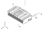
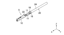
図1から図3までを参照すると、本発明の実施の形態によるコネクタ1は、絶縁体からなる保持部材3と、導電体からなる圧着端子5とを備えている。コネクタ1は複数の圧着端子5を備えるものであるが、図においては1本の圧着端子5のみが示されている。圧着端子5は、その長手方向を前後方向に一致させた状態で、後方から保持部材3に挿入され、保持部材3によって保持される。本実施の形態において、前後方向はX方向であり、前方は+X方向、後方は−X方向である。圧着端子5には、ケーブル20が接続されている。図4に示されるように、ケーブル20は、導電体からなる芯線22と、芯線22を覆う絶縁体からなる外被24とを備えている。本実施の形態のケーブル20の芯線22の材料は、アルミニウム又はアルミニウム合金である。但し、本発明はこれに限定されるわけではなく、芯線22は他の金属からなるものであってもよい。
Referring to FIGS. 1 to 3, a
図4及び図5に示されるように、圧着端子5は、一枚の金属板を打ち抜き、曲げ加工して得られるものである。即ち、本実施の形態の圧着端子5は、複数の部品の組み合わせではなく、単一の部品からなるものである。圧着端子5は、曲げ加工後にキャリア19から切り離される。図示された圧着端子5は、相手側コネクタ(図示せず)の相手側コンタクト(図示せず)と接続されるソケット部10と、芯線22を保持する圧着バレル11と、ケーブル20を外被24の上から保持するケーブル保持部18とを有している。具体的には、圧着バレル11は、ケーブル20の芯線22に巻き付けられ圧着される。ケーブル保持部18は、ケーブル20の外被24上に巻き付けられるようにカシメられる。図4及び図5から理解されるように、ケーブル20の芯線22は、圧着バレル11の内面12上に前後方向(長手方向)に延びるように配置される。その芯線22に対して圧着バレル11を巻き付けるように圧着することで、圧着端子5はケーブル20に接続される。
As shown in FIGS. 4 and 5, the
図5及び図6に示されるように、圧着バレル11の内面12には、互いに独立した複数の窪み15を有するセレーション14が形成されている。複数の窪み15により、圧着時の芯線(電線)22の接触面の摩擦抵抗が増加し、塑性流動による圧着バレル11内の芯線22の減肉を抑制する効果がある。また、窪み15は、圧着時における芯線22の前後方向の伸びも抑制するため、圧着バレル11内の芯線22の減肉が少なく、圧着強度の低下を抑えることができ、安定した電気的接続性能も維持できる。
As shown in FIGS. 5 and 6, a
本実施の形態のセレーション14の窪み15の各々は、圧着バレル11が芯線22に圧着される前の状態(即ち、図5及び図6に示される状態)において、その窪み15の深さ方向と直交する面内(即ち、圧着端子5を構成している金属板の板厚方向と直交する面内)において次の三つの条件を満たす所定形状を有している。(条件1)形状の構成要素として少なくとも二つの直線部とそれらをつなぐ凹曲線部を有している;(条件2)凹曲線部は、所定形状内に向かって凹んでいる;及び(条件3)近接する複数の凹曲線部は、同一の円又は長円上に位置している。
Each of the
所定形状の条件1は、所定形状が少なくとも一つの凹曲線部を含むことを表す。また、凹曲線部の両端には、それぞれ直線部が接続されていることを表す。条件1は、直線部同士が接続されることを否定するものではない。所定形状に含まれる直線部の数は3以上であってよい。所定形状に含まれる凹曲線部の数は、直線部の数と同じかそれよりも少ない。直線部の数と凹曲線部の数とが等しい場合、直線部と凹曲線部とは交互に接続される。
所定形状の条件2は、凹曲線部が、所定形状の外側に向かって突き出したものではないことを明確にしたものである。条件2は、凹曲線部の両端を結ぶ仮想線分を想定したときに、仮想線分が所定形状の外側にあるということもできる。 Condition 2 of the predetermined shape clarifies that the concave curve portion does not protrude toward the outside of the predetermined shape. Condition 2 can also be said that when a virtual line segment connecting both ends of the concave curve portion is assumed, the virtual line segment is outside the predetermined shape.
所定形状の条件3は、凹曲線部が円の一部(円弧)又は長円の一部(円弧及び直線)であること、及びその円又は長円は、近接する凹曲線部に共通であることを表す。この記載から理解されるように、各凹曲線部は、円の一部の場合は円弧のみ、長円の一部の場合は円弧と直線とをつないだものであり、凹んでいても直線のみからなるものは除外される。また、本明細書では、近接する複数の凹曲線部は、互いに異なる窪み15に属しているものとする。即ち、本明細書では、所定形状に複数の凹曲線部が含まれており、それらの凹曲線部間の距離が他の凹曲線部との距離よりも短い場合であっても、互いに近接しているとは言わない。また、本明細書において、“長円”は一対の平行な直線とそれらの両端を結ぶ一対の外側に突き出した半円で形成される形状を指す。
条件1〜条件3を満たす所定形状を有する窪み15の形成に用いられる金型の作成は、図8を参照して後述するように、直線的な切削加工と、円形の穴あけ加工とで実現できる。即ち、金型の作成において、角部に丸みをつけるための難しい曲線的な切削加工や、複雑な形状の電極を用いる放電加工を必要としない。よって、条件1〜条件3を満たす所定形状を有する窪み15で構成されるセレーション14を採用することで、セレーション14を作成するための金型の製造が容易になる。
As will be described later with reference to FIG. 8, the creation of the mold used to form the
図6及び図7に示されるように、本実施の形態の窪み15の所定形状は、全ての角部が円弧状に切り取られた略正三角形である。即ち、所定形状は、三つの直線部151と三つの凹曲線部153とが交互に接続されて構成されている。各凹曲線部153は、二つの直線部151をつないでいる。凹曲線部153は、略正三角形(所定形状)の内側へ凹んでいる。各直線部151の長さL1は、その両端にそれぞれ一端が接続される二つの凹曲線部153の他端間の距離L2よりも短い。すべての窪み15は、互いに同じ構造(形状及びサイズ)を有している。但し、本発明はこれに限定されるわけではなく、条件1〜3を満たしている限り、窪み15の所定形状は、略正三角形以外の形状であってもよい。例えば、正三角形以外の三角形や多角形の角又は辺の一部を円弧状に切り取った形状であってもよい。また、各窪み15は他の窪み15と異なる構造(形状やサイズ)を有していてもよい。例えば、セレーション14には、複数種の窪み15が混在していてもよい。
As shown in FIGS. 6 and 7, the predetermined shape of the
図6及び図7から理解されるように、本実施の形態において、窪み15は、規則的に二次元に配列されている。三つの直線部151がそれぞれ延びる方向に沿って、複数の窪み15が並ぶ窪み列を見ることができる。各窪み15は、三つの直線部151のうちの一つが前後方向と直交するように配置されている。これにより、各窪み15の三つの直線部151のすべてが、前後方向と交差する。各窪み15は、近接する一つ以上の他の窪み15と直線部151同士を対向させるように配置されている。各窪み15は、最大で三つの他の窪み15と近接する。本実施の形態において、互いに近接する二つの窪み15の間隔は、近接する方向にかかわらず一定である。但し、本発明はこれに限らず、近接する二つの窪み15の間隔は、近接する方向毎に異なってもよい。互いに近接する二つの窪み15は、回転対称の関係にある。本実施の形態では、所定形状が略正三角形で、かつ近接する窪み15の間隔が一定なので、互いに近接する二つの窪み15は、鏡像対象の関係でもある。各窪み15の凹曲線部153は、近接する凹曲線部153と同一の仮想の円26上に位置する。本実施の形態では、最大六つの窪み15の六つの凹曲線部153が、一つの円26上に位置している。
As understood from FIGS. 6 and 7, in the present embodiment, the
芯線22に圧着バレル11を圧着させる際、芯線22は、圧着バレル11内部から前後方向の外側に向かって伸びるように加圧変形させられる。窪み15の所定形状の直線部151が前後方向と交差していると、芯線22が圧着バレル11内部から外側に移動することを抑制できる。また、凹曲線部153は、直線部151と同様の働きをするとともに、所定形状から鋭角部分を無くし、圧着バレル11の変形に伴って窪み15の鋭角部分が潰れてしまうことを防止する。これにより、圧着の際に芯線22は、窪み15へ部分的に進入することが可能となる。その結果、圧着バレル11と芯線22との間の電気的、機械的接続安定性が向上する。
When the crimping
窪み15の形成に用いられる金型は、図8に示されるように、窪み15に対応する複数の凸部30を有している。これらの凸部30の形成は、金属ブロック40の一面に直線的な切削加工と穴あけ加工を施すことで実現できる。詳細には、まず、金属ブロック40の一面に、三つの異なる方向に沿った複数の溝42を形成する。このとき、金属ブロック40の一面に残存する部分(残存部)の平面形状が正三角形となるように溝42を形成する。即ち、本実施の形態において、三つの異なる方向は互いに60度の角度で交差する方向であり、三つの異なる方向に沿って形成される複数の溝42の間隔は互いに等しい。各方向に沿って形成される溝42の幅は任意に設定可能であるが、本実施の形態では、全ての溝42の幅を等しくしている。溝42の形成は、単純な直線的な切削加工により実現できる。次に、平面視において、残存部の角部を円弧状に除去するように、穴あけ加工を行って穴44を形成する。この穴あけ加工は、近接する複数の角部に対して同時に行う。このような円形の穴あけ加工は、ドリルを用いて容易に行うことができる。また、円柱状の電極を用いて放電加工を行ってもよい。本実施の形態では、一か所につき、最大6個の角部が含まれるように円形の穴あけ加工を行なう。このような穴あけ加工を行っていることから、穴44に対応する凹曲線部153は、近接する他の凹曲線部153と同一の円上に位置する。以上のようにして製造された金型を用いてプレス加工を行えば、図7に示されるセレーション14を有する圧着バレル11を形成することができる。以上のように、本実施の形態による圧着端子5のセレーション14の形成に用いられる金型は、直線的な切削加工とドリルを用いた穴あけ加工で容易に製造することができる。
As shown in FIG. 8, the mold used for forming the
以上、本発明について実施の形態を掲げて具体的に説明してきたが本発明は、これに限定されるものではなく、種々の変形、変更が可能である。 As described above, the present invention has been specifically described with reference to the embodiments. However, the present invention is not limited thereto, and various modifications and changes can be made.
上記実施の形態では、近接する二つの窪み15の間隔を、その近接方向にかかわらず一定にしている。しかしながら、本発明はこれに限らず、近接する二つの窪み15の間隔を、その近接方向毎に設定してもよい。例えば、図9に示される例では、前後方向に近接する二つの窪み15Aの間隔を、他の方向に近接する窪み15Aの間隔より広くしている。近接する二つの窪み15Aの間隔を、その近接方向毎に設定する場合、直線部151A及び凹曲線部153Aの長さは、各方向における窪み15Aの間隔に依存する。そのため、三つの直線部151Aの長さは互いに異なる場合がある。同様に、三つの凹曲線部153Aの長さは互いに異なる場合がある。それでも、各窪み15Aの所定形状は、条件1〜3を満たしている。即ち、複数の凹曲線部153Aは、同一の円26Aの上に位置する。よって、そのような窪み15Aを有するセレーション14Aの形成に用いられる金型の製造も容易である。
In the above embodiment, the interval between two
上記実施の形態では、窪み15の所定形状を略正三角形としたが、本発明は、これに限られない。例えば、図10に示されるように、窪み15Bの所定形状は、略平行四辺形であってもよい。本例においても、各窪み15Bの所定形状は、条件1〜3を満たしている。詳細には、窪み15Bの所定形状は、四つの直線部151Bと四つの凹曲線部153Bとを有し、直線部151Bと凹曲線部153Bとは交互に接続される。窪み15Bは、直線部151Bが延びる2方向に沿って2次元に配列される。また、窪み15Bは、全ての直線部151Bが前後方向と交差するように配置される。図10の例では、一対の直線部151Bが前後方向と直交している。各窪み15Bの各直線部151Bは、近接する他の窪み15Bの直線部151Bの一つと対向している。各窪み15Bにおいて、四つの各凹曲線部153Bの各々は、他の三つの凹曲線部153Bのいずれかと対向している。また、各窪み15Bの凹曲線部153Bの各々は、近接する他の窪み15Bの凹曲線部153Bと同一の円26B上に位置している。最大四つの窪み15Bの四つの凹曲線部153Bが一つの円26B上に位置する。このような略平行四辺形の所定形状を有する窪み15Bで構成されるセレーション14Bの形成に用いられる金型もまた、直線的な切削加工とドリルを用いる穴あけ加工により容易に製造することができる。
In the above embodiment, the predetermined shape of the
上記実施の形態では、図7に示されるように、多角形の角部に相当する部分に凹曲線部153を設けたが、本発明はこれに限られず、多角形の辺に相当する部分に凹曲線部を設けてもよい。例えば、図11に示され例では、平行四辺形の一対の辺に相当する部分に凹曲線部153Cを設けている。本例においても、各窪み15Cの所定形状は、条件1〜3を満たしている。詳細には、窪み15Cの所定形状は、六つの直線部151Cと、二つの凹曲線部153Cとを有している。各凹曲線部153Cは、二つの直線部151Cをつないでいる。また、各凹曲線部153Cは、所定形状の内側へ凹み、近接する他の凹曲線部153Cと同一の円26C上に位置している。このような窪み15Cで構成されるセレーション14Cの形成に用いられる金型もまた、直線的な切削加工とドリルを用いる穴あけ加工により容易に製造することができる。
In the above embodiment, as shown in FIG. 7, the concave
図12や図13に示されるように、多角形の角部に相当する部分と辺に相当する部分の両方に凹曲線部153D又は153Eを設けてもよい。図12に示される例では、窪み15Dの所定形状は、六つの直線部151Dと、六つの凹曲線部153Dとを有する。また、図13に示される例では、窪み15Eの所定形状は、八つの直線部151Eと、八つの凹曲線部153Eとを有する。いずれの例においても、各窪み15D,15Eの所定形状は、条件1〜3を満たしている。詳細には、直線部151D又は151Eと凹曲線部153D又は153Eとは、交互に接続される。凹曲線部153D及び153Eの各々は、所定形状の内側へ凹み、近接する他の凹曲線部153D又は153Eと同一の円26D又は26E上に位置している。このようなる窪み15D又は15Eで構成されるセレーション14D又は14Eの形成に用いられる金型もまた、直線的な切削加工とドリルを用いる穴あけ加工により容易に製造することができる。
As shown in FIGS. 12 and 13, the
なお、図9から図13は、窪み15A〜15Eの所定形状と配列パターンを説明するためのものであり、圧着バレル11に形成されるセレーション14A〜14Eの一部を抜き出して示している。実際に圧着バレル11に形成されるセレーション14A〜14Eは、X方向に直交する方向(各図における左右方向)へさらに続いている。本発明は、図9から図13に示される例に限定されず、窪み15A〜15Eの数や大きさ、窪み15A〜15Eが形成する窪み列の数を任意に設定することができる。
9 to 13 are for explaining the predetermined shapes and arrangement patterns of the
上記実施の形態では、互いに近接する凹曲線部153は同一の円26上に位置しているが、同一の長円の上に位置してもよい。互いに近接する凹曲線部153が長円上に位置する場合として、互いに近接する窪み15の間隔が、近接方向によって異なる場合が想定される。この場合も、金型の製造は、直線的な切削加工とドリルを用いた穴あけ加工により容易に行える。穴あけ加工を行う際に、ドリルを用いて穴あけを行いつつ直線的にドリルを移動させることにより、長円を容易に形成することができる。なお、凹曲線部の形状は、楕円の一部や多数の頂点を有する多角形(例えば、8角形以上の多角形)の一部などであっても、円や長円の一部の場合と同様の効果が得られる。しかしながら、金型の製造の容易さという観点からは、凹曲線部の形状は、円又は長円形の一部であることが望ましい。
In the above embodiment, the concave
1 コネクタ
3 保持部材
5 圧着端子
10 ソケット部
11 圧着バレル
12 内面
14,14A,14B,14C,14D,14E セレーション
15,15A,15B,15C,15D,15E 窪み
151,151A,151B,151C,151D,151E 直線部
153,153A,153B,153C,153D,153E 凹曲線部
18 ケーブル保持部
19 キャリア
20 ケーブル
22 芯線
24 外被
26 円
30 凸部
40 金属ブロック
42 溝
44 穴
DESCRIPTION OF
Claims (6)
前記圧着バレルの内面には、互いに独立した複数の窪みが形成されており、
前記窪みの夫々は、前記圧着バレルが圧着される前の状態において、前記窪みの深さ方向と直交する面内において所定形状を有しており、
前記所定形状は、少なくとも二つの直線部とそれらをつなぐ一つの曲線部とを有しており、
全ての前記曲線部は、前記所定形状内に向かって凹んでおり、
互いに異なる前記所定形状に含まれる複数の前記曲線部であって、互いに近接する複数の前記曲線部は、同一の円又は長円上に位置している
圧着端子。 A crimp terminal having a crimp barrel crimped to a core wire of the cable,
On the inner surface of the crimp barrel, a plurality of depressions independent of each other are formed,
Each of the dents has a predetermined shape in a plane perpendicular to the depth direction of the dent in a state before the crimp barrel is crimped,
The predetermined shape has at least two straight portions and one curved portion connecting them,
All the curved portions are recessed into the predetermined shape,
A plurality of said curved portion included in different predetermined shapes, the plurality of the curved portions close to each other, crimp terminals are located on the same circle or the oval.
前記直線部は、前記圧着端子の長手方向と交差する方向に延びている
圧着端子。 The crimp terminal according to claim 1,
The crimp terminal, wherein the linear portion extends in a direction intersecting a longitudinal direction of the crimp terminal.
前記所定形状に含まれる前記直線部の数は3以上であり、
前記所定形状に含まれる前記曲線部の数は前記直線部の数と同じであり、
前記所定形状は、前記直線部と前記曲線部とが交互に接続された形状である
圧着端子。 The crimp terminal according to claim 2,
The number of the linear portions included in the predetermined shape is 3 or more,
The number of the curved portions included in the predetermined shape is the same as the number of the linear portions,
The crimp terminal in which the predetermined shape is a shape in which the linear portions and the curved portions are connected alternately.
前記直線部の各々の長さは、その両端にそれぞれ一方の端部が接続される二つの前記曲線部の残りの一方の端部間の距離よりも短い
圧着端子。 The crimp terminal according to claim 3, wherein
A crimp terminal in which a length of each of the straight portions is shorter than a distance between the other one ends of the two curved portions each having one end connected to both ends thereof.
前記所定形状に含まれる前記直線部の数は偶数であり、
前記曲線部の各々は、前記所定形状内において他の前記曲線部のいずれか一つと互いに向かい合っている
圧着端子。 The crimp terminal according to claim 3 or 4, wherein
The number of the linear portions included in the predetermined shape is an even number,
Wherein each of the curved portion, the predetermined shape crimping face each other with any one of the other of the curved portion in the terminal.
A connector comprising: the crimp terminal according to claim 1; and a holding member that holds the crimp terminal.
Priority Applications (3)
| Application Number | Priority Date | Filing Date | Title |
|---|---|---|---|
| JP2015256632A JP6663714B2 (en) | 2015-12-28 | 2015-12-28 | Crimp terminals and connectors |
| US15/359,840 US9711873B1 (en) | 2015-12-28 | 2016-11-23 | Crimp terminal and connector |
| CN201611119166.0A CN106921051B (en) | 2015-12-28 | 2016-12-07 | Crimp type terminal and connector |
Applications Claiming Priority (1)
| Application Number | Priority Date | Filing Date | Title |
|---|---|---|---|
| JP2015256632A JP6663714B2 (en) | 2015-12-28 | 2015-12-28 | Crimp terminals and connectors |
Publications (3)
| Publication Number | Publication Date |
|---|---|
| JP2017120713A JP2017120713A (en) | 2017-07-06 |
| JP2017120713A5 JP2017120713A5 (en) | 2018-11-15 |
| JP6663714B2 true JP6663714B2 (en) | 2020-03-13 |
Family
ID=59087436
Family Applications (1)
| Application Number | Title | Priority Date | Filing Date |
|---|---|---|---|
| JP2015256632A Active JP6663714B2 (en) | 2015-12-28 | 2015-12-28 | Crimp terminals and connectors |
Country Status (3)
| Country | Link |
|---|---|
| US (1) | US9711873B1 (en) |
| JP (1) | JP6663714B2 (en) |
| CN (1) | CN106921051B (en) |
Families Citing this family (14)
| Publication number | Priority date | Publication date | Assignee | Title |
|---|---|---|---|---|
| US10128581B2 (en) * | 2014-06-19 | 2018-11-13 | Fujikura Ltd. | Crimp terminal |
| JP1583222S (en) * | 2016-12-13 | 2017-08-07 | ||
| JP1583221S (en) * | 2016-12-13 | 2017-08-07 | ||
| JP1583220S (en) * | 2016-12-13 | 2017-08-07 | ||
| JP1587160S (en) * | 2017-03-09 | 2017-10-02 | ||
| JP1590186S (en) * | 2017-03-09 | 2017-11-06 | ||
| JP1587159S (en) * | 2017-03-09 | 2017-10-02 | ||
| JP1590185S (en) * | 2017-03-09 | 2017-11-06 | ||
| JP1633599S (en) | 2018-07-02 | 2019-06-10 | ||
| KR102078164B1 (en) * | 2018-07-23 | 2020-02-17 | 한국단자공업 주식회사 | Terminal |
| JP1703926S (en) * | 2021-06-22 | 2022-01-04 | ||
| JP1703925S (en) * | 2021-06-22 | 2022-01-04 | ||
| JP1703924S (en) * | 2021-06-22 | 2022-01-04 | ||
| JP1703927S (en) * | 2021-06-23 | 2022-01-04 |
Family Cites Families (11)
| Publication number | Priority date | Publication date | Assignee | Title |
|---|---|---|---|---|
| JPH05152011A (en) * | 1991-11-26 | 1993-06-18 | Sumitomo Wiring Syst Ltd | Crimp-style terminal |
| DE19549174A1 (en) * | 1995-10-28 | 1997-07-03 | Bosch Gmbh Robert | Contact element with crimp section |
| JP5071288B2 (en) | 2008-07-22 | 2012-11-14 | 住友電装株式会社 | Terminal fittings and wires with terminal fittings |
| JP2010027505A (en) | 2008-07-23 | 2010-02-04 | Sumitomo Wiring Syst Ltd | Terminal metal fastener, and wire having the same |
| US7722416B2 (en) * | 2008-10-02 | 2010-05-25 | Delphi Technologies, Inc. | Electrical connection system for use on aluminum wires |
| JP4979147B2 (en) | 2009-04-24 | 2012-07-18 | 株式会社オートネットワーク技術研究所 | Terminal fittings and electric wires with terminal fittings |
| JP5690095B2 (en) | 2010-08-04 | 2015-03-25 | 矢崎総業株式会社 | Crimp terminal |
| US8622774B2 (en) * | 2011-11-07 | 2014-01-07 | Delphi Technologies, Inc. | Electrical contact having channel with angled sidewalls and romboid knurl pattern |
| JP2015076236A (en) | 2013-10-08 | 2015-04-20 | 矢崎総業株式会社 | Crimping terminal |
| JP5940102B2 (en) | 2013-11-01 | 2016-06-29 | 古河電気工業株式会社 | Terminal fittings and wires with terminals |
| JP6278675B2 (en) * | 2013-11-28 | 2018-02-14 | 日本航空電子工業株式会社 | Crimp terminal and connector |
-
2015
- 2015-12-28 JP JP2015256632A patent/JP6663714B2/en active Active
-
2016
- 2016-11-23 US US15/359,840 patent/US9711873B1/en active Active
- 2016-12-07 CN CN201611119166.0A patent/CN106921051B/en active Active
Also Published As
| Publication number | Publication date |
|---|---|
| CN106921051B (en) | 2018-12-21 |
| US20170187127A1 (en) | 2017-06-29 |
| CN106921051A (en) | 2017-07-04 |
| US9711873B1 (en) | 2017-07-18 |
| JP2017120713A (en) | 2017-07-06 |
Similar Documents
| Publication | Publication Date | Title |
|---|---|---|
| JP6663714B2 (en) | Crimp terminals and connectors | |
| JP6278675B2 (en) | Crimp terminal and connector | |
| EP2546931B1 (en) | Connecting structure of aluminum conductor and connector | |
| EP2602877B1 (en) | Crimp terminal | |
| JP6278024B2 (en) | connector | |
| KR101540467B1 (en) | Crimping terminal | |
| JP2012009178A (en) | Press-fit terminal and press-fit terminal manufacturing method | |
| US10128581B2 (en) | Crimp terminal | |
| JP2010049843A (en) | Terminal fitting | |
| WO2016143466A1 (en) | Electric wire with terminal, and terminal | |
| JP2015090739A (en) | Crimp terminal | |
| WO2015053255A1 (en) | Crimp terminal | |
| WO2013172457A1 (en) | Female terminal | |
| WO2015118930A1 (en) | Female terminal | |
| JP2015076235A (en) | Crimping terminal | |
| WO2021124949A1 (en) | Crimp terminal and terminal-equipped electric wire | |
| WO2021124897A1 (en) | Crimp terminal, and electric wire with terminal | |
| WO2015122329A1 (en) | Female terminal | |
| JP6528808B2 (en) | Terminal and method of manufacturing the terminal | |
| JP6440468B2 (en) | Crimp terminal | |
| JP2019114516A (en) | Wire with terminal | |
| JP6420128B2 (en) | Crimp terminal | |
| WO2013179919A1 (en) | Female terminal | |
| JP6809811B2 (en) | Wire with terminal and wire harness | |
| JP6359861B2 (en) | Terminal |
Legal Events
| Date | Code | Title | Description |
|---|---|---|---|
| A521 | Request for written amendment filed |
Free format text: JAPANESE INTERMEDIATE CODE: A523 Effective date: 20181002 |
|
| A621 | Written request for application examination |
Free format text: JAPANESE INTERMEDIATE CODE: A621 Effective date: 20181002 |
|
| A977 | Report on retrieval |
Free format text: JAPANESE INTERMEDIATE CODE: A971007 Effective date: 20190606 |
|
| A131 | Notification of reasons for refusal |
Free format text: JAPANESE INTERMEDIATE CODE: A131 Effective date: 20190626 |
|
| A521 | Request for written amendment filed |
Free format text: JAPANESE INTERMEDIATE CODE: A523 Effective date: 20190802 |
|
| A02 | Decision of refusal |
Free format text: JAPANESE INTERMEDIATE CODE: A02 Effective date: 20191106 |
|
| A521 | Request for written amendment filed |
Free format text: JAPANESE INTERMEDIATE CODE: A523 Effective date: 20191205 |
|
| A911 | Transfer to examiner for re-examination before appeal (zenchi) |
Free format text: JAPANESE INTERMEDIATE CODE: A911 Effective date: 20191213 |
|
| TRDD | Decision of grant or rejection written | ||
| A01 | Written decision to grant a patent or to grant a registration (utility model) |
Free format text: JAPANESE INTERMEDIATE CODE: A01 Effective date: 20200129 |
|
| A61 | First payment of annual fees (during grant procedure) |
Free format text: JAPANESE INTERMEDIATE CODE: A61 Effective date: 20200217 |
|
| R150 | Certificate of patent or registration of utility model |
Ref document number: 6663714 Country of ref document: JP Free format text: JAPANESE INTERMEDIATE CODE: R150 |
|
| R250 | Receipt of annual fees |
Free format text: JAPANESE INTERMEDIATE CODE: R250 |
|
| R250 | Receipt of annual fees |
Free format text: JAPANESE INTERMEDIATE CODE: R250 |