以下、本発明の実施形態について、図面を参照しながら説明する。
Hereinafter, embodiments of the present invention will be described with reference to the drawings.
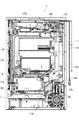
図1は、パチンコ遊技機(以下、「パチンコ機」と略称する。)1の正面図である。また、図2は、パチンコ機1の背面図である。パチンコ機1は、遊技球を遊技媒体として用いるものであり、遊技者は、遊技場運営者から遊技球を借り受けてパチンコ機1による遊技を行う。なお、パチンコ機1における遊技において、遊技球はその1個1個が遊技価値を有した媒体であり、遊技の成果として遊技者が享受する特典(利益)は、例えば遊技者が獲得した遊技球の数に基づいて遊技価値に換算することができる。以下、図1及び図2を参照しつつパチンコ機1の全体構成について説明する。
FIG. 1 is a front view of a pachinko gaming machine (hereinafter, abbreviated as “pachinko machine”) 1. FIG. 2 is a rear view of the pachinko machine 1. The pachinko machine 1 uses a game ball as a game medium, and a player borrows a game ball from a game arcade operator to play a game with the pachinko machine 1. In the game in the pachinko machine 1, each game ball is a medium having a game value, and a privilege (profit) enjoyed by the player as a result of the game is, for example, a game ball acquired by the player. Can be converted into a game value based on the number of games. Hereinafter, the overall configuration of the pachinko machine 1 will be described with reference to FIGS.
〔全体構成〕
パチンコ機1は、その本体として主に外枠ユニット2、一体扉ユニット4及び内枠アセンブリ(プラ枠、遊技機枠)7を備えている。遊技者に相対する正面から視て、その最も前面側には一体扉ユニット4が位置している。一体扉ユニット4の背面側(奥側)には内枠アセンブリ7が位置しており、内枠アセンブリ7の外側を囲むようにして外枠ユニット2が配置されている。
〔overall structure〕
The pachinko machine 1 mainly includes an outer frame unit 2, an integral door unit 4, and an inner frame assembly (plastic frame, game machine frame) 7 as its main body. When viewed from the front facing the player, the integrated door unit 4 is located on the most front side thereof. The inner frame assembly 7 is located on the back side (rear side) of the integrated door unit 4, and the outer frame unit 2 is arranged so as to surround the outside of the inner frame assembly 7.
外枠ユニット2は、木材及び金属材を縦長の矩形状に組み合わせた構造体であり、この外枠ユニット2は、遊技場内の島設備(図示外)に対してねじ等の締結具を用いて固定されるものである。なお、縦長矩形状の外枠ユニット2において、上下の短辺に相当する部位には木材が用いられており、左右の長辺に相当する部位には金属材が用いられている。
The outer frame unit 2 is a structure in which wood and metal materials are combined in a vertically long rectangular shape, and the outer frame unit 2 uses fasteners such as screws for island facilities (not shown) in the game arcade. It is fixed. In the vertically long rectangular outer frame unit 2, wood is used for portions corresponding to upper and lower short sides, and metal material is used for portions corresponding to left and right long sides.
一体扉ユニット4は、その下部位置に受皿ユニット6が一体化された構造である。一体扉ユニット4及び内枠アセンブリ7は、外枠ユニット2を介して島設備に取り付けられ、これらはそれぞれ図示しないヒンジ機構を介して開閉式に動作する。図示しないヒンジ機構の開閉軸線は、パチンコ機1の正面から視て左側端部に沿って垂直方向に延びている。
The integrated door unit 4 has a structure in which the pan unit 6 is integrated at a lower position. The integral door unit 4 and the inner frame assembly 7 are attached to the island facility via the outer frame unit 2, and each of them operates in an openable / closable manner via a hinge mechanism (not shown). The open / close axis of the hinge mechanism (not shown) extends vertically along the left end when viewed from the front of the pachinko machine 1.
図1中の正面から視て内枠アセンブリ7の右側縁部(図2では左側縁部)には、その内側に統一錠ユニット9が設けられている。また、これに対応して一体扉ユニット4及び外枠ユニット2の右側縁部(裏側)にも、それぞれ図示しない施錠具が設けられている。図1に示されるように、外枠ユニット2に対して一体扉ユニット4及び内枠アセンブリ7が閉じた状態で、その裏側にある統一錠ユニット9は施錠具とともに一体扉ユニット4及び内枠アセンブリ7の開放を不能にしている。
A unified lock unit 9 is provided inside the right edge (the left edge in FIG. 2) of the inner frame assembly 7 when viewed from the front in FIG. Correspondingly, a locking device (not shown) is provided on each of the right side edges (back side) of the integral door unit 4 and the outer frame unit 2. As shown in FIG. 1, in a state in which the integral door unit 4 and the inner frame assembly 7 are closed with respect to the outer frame unit 2, the unified lock unit 9 on the rear side of the integral door unit 4 and the inner frame assembly 7 The opening of 7 has been disabled.
また、受け皿ユニット6の右側縁部には鍵穴付きのシリンダ錠6aが設けられている。例えば、遊技場の管理者が専用キーを鍵穴に差し込んでシリンダ錠6aを時計回りに捻ると、統一錠ユニット9が作動して内枠アセンブリ7とともに一体扉ユニット4の開放が可能な状態となる。これら全体を外枠ユニット2から前面側へ開放する(扉のように動かす)と、前面側にてパチンコ機1の裏側が露出することになる。
A cylinder lock 6 a with a keyhole is provided on the right side edge of the tray unit 6. For example, when the manager of the game arcade inserts the dedicated key into the keyhole and twists the cylinder lock 6a clockwise, the unified lock unit 9 operates and the integrated door unit 4 can be opened together with the inner frame assembly 7. . When the entirety is opened from the outer frame unit 2 to the front side (moved like a door), the back side of the pachinko machine 1 is exposed at the front side.
一方、シリンダ錠6aを反時計回りに捻ると、内枠アセンブリ7は施錠されたままで一体扉ユニット4の施錠だけが解除され、一体扉ユニット4が開放可能となる。一体扉ユニット4を前面側へ開放すると遊技盤ユニット8が直に露出し、この状態で遊技場の管理者が盤面内での球詰まり等の障害を取り除くことができる。また、一体扉ユニット4を開放すると、受け皿ユニット6も一緒に前面側へ開放される。
On the other hand, when the cylinder lock 6a is twisted counterclockwise, only the locking of the integral door unit 4 is released while the inner frame assembly 7 remains locked, and the integral door unit 4 can be opened. When the integrated door unit 4 is opened to the front side, the game board unit 8 is directly exposed, and in this state, the manager of the game hall can remove obstacles such as clogging of balls in the board. When the integrated door unit 4 is opened, the tray unit 6 is also opened to the front side together.
また、パチンコ機1は、遊技用ユニットとして上記の遊技盤ユニット8を備えている。遊技盤ユニット8は、一体扉ユニット4の背後(内側)で上記の内枠アセンブリ7に支持されている。遊技盤ユニット8は、例えば一体扉ユニット4を前面側へ開放した状態で内枠アセンブリ7に対して着脱可能である。一体扉ユニット4には、その中央部に縦長円形状の窓4aが形成されており、この窓4a内にガラスユニット(参照符号なし)が取り付けられている。ガラスユニットは、例えば窓4aの形状に合わせてカットされた2枚の透明板(ガラス板)を組み合わせたものである。ガラスユニットは、一体扉ユニット4の裏側に図示しない取り付け具を介して取り付けられる。遊技盤ユニット8の前面には遊技領域8a(盤面、遊技盤)が形成されており、この遊技領域8aは窓4aを通じて前面側から遊技者に視認可能である。一体扉ユニット4が閉じられると、ガラスユニットの内面と盤面との間に遊技球が流下できる空間が形成される。
In addition, the pachinko machine 1 includes the gaming board unit 8 as a gaming unit. The game board unit 8 is supported by the inner frame assembly 7 behind (inside) the integrated door unit 4. The game board unit 8 is detachable from the inner frame assembly 7 with the integrated door unit 4 opened to the front side, for example. The integrated door unit 4 has a vertically long window 4a formed in the center thereof, and a glass unit (no reference numeral) is mounted in the window 4a. The glass unit is, for example, a combination of two transparent plates (glass plates) cut in accordance with the shape of the window 4a. The glass unit is attached to the back side of the integrated door unit 4 via an attachment (not shown). A game area 8a (board surface, game board) is formed on the front surface of the game board unit 8, and the game area 8a is visible to the player from the front side through the window 4a. When the integrated door unit 4 is closed, a space is formed between the inner surface of the glass unit and the board surface, in which game balls can flow down.
受け皿ユニット6は、全体的に一体扉ユニット4から前面側へ突出した形状をなしており、その上面に上皿6bが形成されている。この上皿6bには、遊技者に貸し出された遊技球(貸球)や入賞により獲得した遊技球(賞球)を貯留することができる。また、受け皿ユニット6には、上皿6bの下段位置に下皿6cが形成されている。この下皿6cには、上皿6bが満杯の状態でさらに払い出された遊技球が貯留される。なお、本実施形態のパチンコ機1はいわゆるCR機(CRユニットに接続する機種)であり、遊技者が借り受けた遊技球は、賞球とは別に裏側の払出装置ユニット172から受け皿ユニット6(上皿6b又は下皿6c)に払い出される。
The receiving tray unit 6 has a shape projecting from the integral door unit 4 to the front side as a whole, and an upper tray 6b is formed on the upper surface thereof. In the upper plate 6b, game balls (lending balls) lent to the player and game balls (prize balls) obtained by winning can be stored. In the tray unit 6, a lower plate 6c is formed at a lower position of the upper plate 6b. In the lower plate 6c, game balls further paid out while the upper plate 6b is full are stored. Note that the pachinko machine 1 of the present embodiment is a so-called CR machine (a model connected to a CR unit), and game balls borrowed by a player are separated from the prize balls by the payout device unit 172 on the back side and the saucer unit 6 (upper). Dispensed to plate 6b or lower plate 6c).
受け皿ユニット6の上面には貸出操作部14が設けられており、この貸出操作部14には、球貸ボタン10及び返却ボタン12が配置されている。図示しないCRユニットに有価媒体(例えば磁気記録媒体、記憶IC内蔵媒体等)を投入した状態で球貸ボタン10を遊技者が操作すると、予め決められた度数単位(例えば5度数)に対応する個数(例えば125個)分の遊技球が貸し出される。このため貸出操作部14の上面には度数表示部(図示省略)が配置されており、この度数表示部には、CRユニットに投入されている有価媒体の残存度数が表示される。なお、遊技者は、返却ボタン12を操作することで、度数が残存している有価媒体の返却を受けることができる。本実施形態ではCR機を例に挙げているが、パチンコ機1はCR機とは別の現金機(CRユニットに接続されない機種)であってもよい。
A lending operation unit 14 is provided on the upper surface of the saucer unit 6, and a ball lending button 10 and a return button 12 are arranged on the lending operation unit 14. When a player operates the ball lending button 10 in a state where a valuable medium (for example, a magnetic recording medium, a storage IC built-in medium, or the like) is inserted into a CR unit (not shown), the number corresponding to a predetermined frequency unit (for example, 5 frequencies) (For example, 125) game balls are lent out. For this reason, a frequency display unit (not shown) is arranged on the upper surface of the lending operation unit 14, and the frequency display unit displays the remaining frequency of the valuable medium inserted into the CR unit. By operating the return button 12, the player can receive a valuable medium with a remaining frequency. In the present embodiment, the CR machine is taken as an example, but the pachinko machine 1 may be a cash machine (a model not connected to the CR unit) different from the CR machine.
また、受け皿ユニット6の上面には、上段位置にある上皿6bの手前に上皿球抜きボタン6dが設置されており、そして下皿6cの手前でその中央部には下皿球抜きレバー6eが設置されている。遊技者は上皿球抜きボタン6dを例えば押し込み操作することで、上皿6bに貯留された遊技球を下皿6cへ流下させることができる。また、遊技者は、下皿球抜きレバー6eを例えば左方向へスライドさせることで、下皿6cに貯留された遊技球を下方へ落下させて排出することができる。排出された遊技球は、例えば図示しない球受け箱等に受け止められる。
On the upper surface of the tray unit 6, an upper plate ball removing button 6d is provided in front of the upper plate 6b at the upper position, and in the center of the lower plate ball removing lever 6e in front of the lower plate 6c. Is installed. The player can cause the game balls stored in the upper plate 6b to flow down to the lower plate 6c by, for example, pressing the upper plate ball removal button 6d. Further, the player can drop the game balls stored in the lower plate 6c downward and discharge them by sliding the lower plate ball pulling lever 6e, for example, to the left. The discharged game balls are received in, for example, a ball receiving box (not shown).
受け皿ユニット6の右下部には、ハンドルユニット16が設置されている。遊技者はこのハンドルユニット16を操作することで発射制御基板セット174を作動させ、遊技領域8aに向けて遊技球を発射する(打ち込む)ことができる(球発射装置)。発射された遊技球は、遊技盤ユニット8の下縁部から左側縁部に沿って上昇し、図示しない外バンドに案内されて遊技領域8a内に放り込まれる。遊技領域8a内には多数の障害釘や風車(図中参照符号なし)等が配置されており、放り込まれた遊技球は障害釘や風車により誘導・案内されながら遊技領域8a内を流下する。なお、遊技領域8a内(盤面、遊技盤)の構成については、別の図面を参照しながらさらに後述する。
A handle unit 16 is provided at a lower right portion of the tray unit 6. The player operates the handle control unit 16 to operate the firing control board set 174, and can shoot (hit) a game ball toward the game area 8a (ball firing device). The launched game balls rise from the lower edge of the game board unit 8 along the left edge, are guided by an outer band (not shown), and are thrown into the game area 8a. A number of obstacle nails and windmills (without reference numerals in the figure) are arranged in the game area 8a, and the thrown game balls flow down in the game area 8a while being guided and guided by the obstacle nails and windmill. The configuration of the game area 8a (the board surface, the game board) will be further described later with reference to another drawing.
〔枠前面の構成〕
一体扉ユニット4には、演出用の構成要素として左トップレンズユニット47及び右上電飾ユニット49が設置されている。このうち左トップレンズユニット47にはガラス枠トップランプ46及び左側のガラス枠装飾ランプ48が組み込まれており、右上電飾ユニット49には右側のガラス枠装飾ランプ50が組み込まれている。その他にも一体扉ユニット4には、左トップレンズユニット47及び右上電飾ユニット49の下方にそれぞれ連なるようにして左右のガラス枠装飾ランプ52が設置されており、これらガラス枠装飾ランプ52は、一体扉ユニット4の左右縁部から受皿ユニット6の前面部にまで回り込むようにして延びている。一体扉ユニット4においてガラス枠トップランプ46や左右のガラス枠装飾ランプ48,50,52等は、ガラスユニットを取り巻くようにして配置されている。
[Configuration of front of frame]
In the integrated door unit 4, a left top lens unit 47 and an upper right illuminated unit 49 are installed as constituent elements for the effect. The left top lens unit 47 incorporates a glass frame top lamp 46 and a left glass frame decoration lamp 48, and the right upper illumination unit 49 incorporates a right glass frame decoration lamp 50. In addition, left and right glass frame decorative lamps 52 are installed on the integrated door unit 4 so as to be continuous below the left top lens unit 47 and the upper right electric unit 49, respectively. It extends so as to extend from the left and right edges of the integrated door unit 4 to the front surface of the pan unit 6. In the integrated door unit 4, the glass frame top lamp 46 and the left and right glass frame decorative lamps 48, 50, 52 and the like are arranged so as to surround the glass unit.
上述した各種ランプ46,48,50,52は、例えば内蔵するLEDの発光(点灯や点滅、輝度階調の変化、色調の変化等)により演出を実行する。また、一体扉ユニット4の上部において、左トップレンズユニット47及び右上電飾ユニット49にはそれぞれガラス枠上スピーカ54,55が組み込まれている。一方、外枠ユニット2の左下位置には外枠スピーカ56が組み込まれている。これらスピーカ54,55,56は、効果音やBGM、音声等(音響全般)を出力して演出を実行するものである。
The above-described various lamps 46, 48, 50, and 52 execute an effect by, for example, light emission (lighting or blinking, change in luminance gradation, change in color tone, etc.) of a built-in LED. On the upper part of the integrated door unit 4, the left top lens unit 47 and the right upper illumination unit 49 incorporate speakers 54 and 55 on the glass frame, respectively. On the other hand, an outer frame speaker 56 is incorporated at a lower left position of the outer frame unit 2. These speakers 54, 55, and 56 execute effects by outputting sound effects, BGM, voice, and the like (general sound).
また、受け皿ユニット6の中央には、上皿6bの手前位置に演出切替ボタン45が設置されている。遊技者は、この演出切替ボタン45を押し込み操作することで演出内容(例えば液晶表示器42に表示される背景画面)を切り替えたり、例えば図柄の変動中や大当りの確定表示中、あるいは大当り遊技中に何らかの演出(予告演出、確変昇格演出、大役中の昇格演出等)を発生させたりすることができる。
At the center of the tray unit 6, an effect switching button 45 is provided at a position in front of the upper plate 6b. The player switches the effect contents (for example, the background screen displayed on the liquid crystal display 42) by pressing and pressing the effect switching button 45, for example, during the change of the symbol, during the fixed display of the big hit, or during the big hit game. , A certain effect (notification effect, probable change promotion effect, promotion effect in the role of a large part, etc.) can be generated.
さらに、演出切替ボタン45の周囲には、演出切替ボタン45を取り囲むようにジョグダイヤル45aが設置されている(操作入力受付手段、回転型セレクター)。遊技者は、このジョグダイヤル45aを回転させることで、例えば液晶表示部42に表示される演出内容を変化させることができる。
Further, a jog dial 45a is provided around the effect switching button 45 so as to surround the effect switching button 45 (operation input receiving means, rotary selector). By rotating the jog dial 45a, the player can change the effect contents displayed on the liquid crystal display unit 42, for example.
〔裏側の構成〕
図2に示されているように、パチンコ機1の裏側には、電源制御ユニット162や主制御基板ユニット170、払出装置ユニット172、流路ユニット173、発射制御基板セット174、払出制御基板ユニット176、裏カバーユニット178等が設置されている。この他にパチンコ機1の裏側には、パチンコ機1の電源系統や制御系統を構成する各種の電子機器類(図示外の制御コンピュータを含む)や外部端子板160、電源コード(電源プラグ)164、アース線(アース端子)166、図示しない接続配線等が設置されている。
[Back side configuration]
As shown in FIG. 2, on the back side of the pachinko machine 1, a power supply control unit 162, a main control board unit 170, a dispensing device unit 172, a flow path unit 173, a firing control board set 174, and a dispensing control board unit 176 are provided. , A back cover unit 178 and the like. In addition, on the back side of the pachinko machine 1, various electronic devices (including a control computer (not shown)) constituting the power supply system and control system of the pachinko machine 1, the external terminal board 160, the power cord (power plug) 164 , A ground wire (ground terminal) 166, connection wiring (not shown), and the like.
上記の払出装置ユニット172は、例えば賞球タンク172a及び賞球ケース(参照符号なし)を有しており、このうち賞球タンク172aは内枠アセンブリ7の上縁部(裏側)に設置された状態で、図示しない補給経路から補給された遊技球を蓄えることができる。賞球タンク172aに蓄えられた遊技球は、図示しない上側賞球樋を通じて賞球ケースに導かれる。流路ユニット173は、払出装置ユニット172から送り出された遊技球を前面側の受け皿ユニット6に向けて案内する。
The payout device unit 172 has, for example, a prize ball tank 172a and a prize ball case (no reference numeral). The prize ball tank 172a is installed on the upper edge (back side) of the inner frame assembly 7. In this state, game balls supplied from a supply path (not shown) can be stored. The game balls stored in the prize ball tank 172a are guided to a prize ball case through an upper prize ball gutter (not shown). The channel unit 173 guides the game balls sent out from the payout device unit 172 toward the tray unit 6 on the front side.
また、上記の外部端子板160は、パチンコ機1を外部の電子機器(例えばデータ表示装置、ホールコンピュータ等)に接続するためのものであり、この外部端子板160からは、パチンコ機1の遊技進行状態やメンテナンス状態等を表す各種の外部情報信号(例えば賞球情報、扉開放情報、図柄確定回数情報、大当り情報、始動口情報等)が外部の電子機器に向けて出力されるものとなっている。
The above-mentioned external terminal board 160 is for connecting the pachinko machine 1 to an external electronic device (for example, a data display device, a hall computer, etc.). Various external information signals (for example, prize ball information, door opening information, symbol determination frequency information, jackpot information, start-up information, etc.) representing the progress state and the maintenance state are output to external electronic devices. ing.
電源コード164は、例えば遊技場の島設備に設置された電源装置(例えばAC24V)に接続されることで、パチンコ機1の動作に必要な電源(電力)を確保するものである。また、アース線166は、同じく島設備に設置されたアース端子に接続されることで、パチンコ機1のアース(接地)を確保するものである。
The power cord 164 is, for example, connected to a power supply (for example, 24 VAC) installed in the island facilities of the game arcade to secure a power supply (electric power) necessary for the operation of the pachinko machine 1. In addition, the ground wire 166 is connected to a ground terminal also installed in the island facility to secure the ground (ground) of the pachinko machine 1.
〔遊技盤ユニットの構成〕
図3は、遊技盤ユニット8を単独で示す正面図である。遊技盤ユニット8は、ベースとなる遊技板8bを備えており、この遊技板8bの前面側に遊技領域8aが形成されている。遊技板8bは、例えば透明樹脂板で構成されており、遊技盤ユニット8が内枠アセンブリ7に固定された状態で、遊技板8bの前面はガラスユニットに平行となる。遊技板8bの前面には、略円形状に設置された発射レール(参照符号なし)の内側に上記の遊技領域8aが形成されている。
[Composition of the game board unit]
FIG. 3 is a front view showing the game board unit 8 alone. The game board unit 8 includes a game board 8b serving as a base, and a game area 8a is formed on the front side of the game board 8b. The game board 8b is made of, for example, a transparent resin plate, and the front surface of the game board 8b is parallel to the glass unit with the game board unit 8 fixed to the inner frame assembly 7. On the front surface of the game board 8b, the above-mentioned game area 8a is formed inside a firing rail (no reference numeral) installed in a substantially circular shape.
遊技領域8a内には、その中央位置に比較的大型の演出ユニット40が配置されており、この演出ユニット40を中心として遊技領域8aが左側部分、右側部分及び下部分に大きく分かれている。遊技領域8aの左側部分は、通常遊技状態(低確率非時間短縮状態)で使用される第1遊技領域(左打ち領域)であり、遊技領域8aの右側部分は、有利遊技状態(大当り遊技状態、小当り遊技状態、低確率時間短縮状態、高確率時間短縮状態等)で使用される第2遊技領域(右打ち領域、特定遊技領域)である。遊技球は、第2遊技領域へ流通させる経路に係る流通領域(発射レールや遊技領域の天井部、誘導部など)によって第2遊技領域に導かれる。また、遊技領域8a内には、演出ユニット40の周辺に中始動入賞口26、始動ゲート(ゲート)20、普通入賞口22,24、可変始動入賞装置(特定入賞装置、第1入賞装置)28、第1可変入賞装置(特別入賞装置)30、第2可変入賞装置(特別入賞装置、可変入賞装置)31、第1振分装置200、第2振分装置(振分装置)210、第1非電動入賞装置(第1非電動役物)220、第2非電動入賞装置(第2非電動役物)230等が分布して設置されている。始動ゲート20は、流通領域から右打ち領域へ導かれた遊技球を主対象にして通過させることで作動抽選(普通図柄抽選)の抽選契機を発生させる。
In the game area 8a, a relatively large effect unit 40 is arranged at the center thereof, and the game area 8a is largely divided into a left portion, a right portion, and a lower portion around the effect unit 40. The left part of the game area 8a is a first game area (left hit area) used in a normal game state (low probability non-time shortened state), and the right part of the game area 8a is an advantageous game state (big hit game state). , A small hitting game state, a low probability time reduction state, a high probability time reduction state, etc.). The game ball is guided to the second game area by a distribution area (e.g., a launch rail, a ceiling of the game area, a guide section, etc.) along a route to be distributed to the second game area. Also, in the game area 8a, a medium starting winning opening 26, a starting gate (gate) 20, normal winning openings 22, 24, a variable starting winning device (specific winning device, first winning device) 28 around the effect unit 40. , A first variable prize device (special prize device) 30, a second variable prize device (special prize device, variable prize device) 31, a first distribution device 200, a second distribution device (distribution device) 210, a first A non-motorized winning device (first non-motorized character) 220, a second non-motorized winning device (second non-motorized character) 230, and the like are distributed and installed. The starting gate 20 generates a lottery opportunity of an operation lottery (normal symbol lottery) by passing the game ball guided from the distribution area to the right-handed area as the main object.
このうち、中始動入賞口26は、遊技領域8aの下部分の中央に配置されている。始動ゲート20、可変始動入賞装置28、第1振分装置200、第2可変入賞装置31、普通入賞口24(第2入賞口)、第2振分装置210、第1非電動入賞装置220、第2非電動入賞装置230、及び第1可変入賞装置30は、遊技領域8aの右側部分に上からこの順番で配置されている。ここで、可変始動入賞装置28は、始動ゲート20の下方に配置され、第1振分装置200は、可変始動入賞装置28の左下に配置されている。第2可変入賞装置31は、第1振分装置200の右下(右振分通路の下)に配置され、第2振分装置210は、第2可変入賞装置31の左下に配置されている。第1非電動入賞装置220は、第2振分装置210の右下に配置され、第2非電動入賞装置230は、第1非電動入賞装置220の下方に配置されている。また、第1可変入賞装置30は、第2非電動入賞装置230及び第2振分装置210の左下であって中始動入賞口26の右側に配置されている。さらに、左側の3つの普通入賞口22は遊技領域8aの左側部分(左打ち領域)に配置され、右側の1つの普通入賞口(所定の入賞口)24は第1振分装置200の下(左振分通路の下)に配置されている。
Among them, the middle start winning opening 26 is arranged at the center of the lower part of the game area 8a. Starting gate 20, variable starting winning device 28, first sorting device 200, second variable winning device 31, normal winning opening 24 (second winning opening), second sorting device 210, first non-motorized winning device 220, The second non-motorized winning device 230 and the first variable winning device 30 are arranged in this order from the top on the right side of the gaming area 8a. Here, the variable start winning device 28 is arranged below the start gate 20, and the first distribution device 200 is arranged at the lower left of the variable start winning device 28. The second variable prize device 31 is disposed at the lower right of the first distribution device 200 (below the right distribution path), and the second distribution device 210 is disposed at the lower left of the second variable prize device 31. . The first non-motorized winning device 220 is arranged at the lower right of the second distribution device 210, and the second non-motorized winning device 230 is arranged below the first non-motorized winning device 220. The first variable winning device 30 is disposed at the lower left of the second non-motorized winning device 230 and the second sorting device 210 and to the right of the middle starting winning opening 26. Further, the three normal winning ports 22 on the left side are arranged in the left portion (left hit area) of the game area 8a, and the one normal winning port (predetermined winning port) 24 on the right side is below the first distribution device 200 ( (Under the left distribution passage).
また、始動ゲート20の上方には、4つの障害釘(参照符号なし)が配置されており、さらにその上方には入球口19a及び放出口19bが配置されている。入球口19aと放出口19bとは図示しない裏側の連絡通路によって連結されている。入球口19aに入球した遊技球は、この連絡通路を通って減速・整流され、放出口19bから放出される。
Further, four obstacle nails (without reference numerals) are arranged above the starting gate 20, and further above that, a ball entrance 19a and a discharge port 19b are arranged. The entrance 19a and the exit 19b are connected by a communication passage on the back side (not shown). The game ball that has entered the entrance 19a is decelerated and straightened through this communication path, and is released from the release 19b.
さらに、始動ゲート20の右側にはアウト口(所定の入球口)19cが配置されている。放出口19bから放出された遊技球は、基本的には真っ直ぐに落下して始動ゲート20を通過するが、障害釘によって右側に弾かれた場合にはアウト口19cに入球する。
Further, on the right side of the starting gate 20, an out port (predetermined entrance port) 19c is arranged. The game ball discharged from the discharge port 19b basically falls straight and passes through the starting gate 20, but enters the out port 19c when hit by the obstacle nail to the right.
遊技領域8aの最上部には、遊技領域8aの上部に向かって発射された遊技球の移動方向を規制可能として右打ち領域に導くための入口領域(例えば演出ユニット40の上部に形成された一列の通路の入口)と出口領域(例えば放出口19b)を有する区画に基づく上部誘導通路(誘導部)19eが形成されている。上部誘導通路19eの出口領域は、右打ち領域の上流領域に連通して配置され、第1振分装置200は、可変始動入賞装置28に入球しなかった遊技球を1個ずつ第1振分装置200の内部へ通過可能とさせる流入口200iに向けて流下させ得る右打ち領域内の構成部位における下流領域に配置され、第2可変入賞装置31は、第1振分装置200の下流領域に配置されている。
At the top of the game area 8a, an entrance area (for example, a row formed above the effect unit 40) for guiding the movement direction of the game ball fired toward the upper part of the game area 8a to the right-handed area can be regulated. An upper guide passage (guide portion) 19e is formed based on a section having an entrance of the passage (not shown) and an outlet region (for example, the discharge port 19b). The exit area of the upper guide passage 19e is arranged in communication with the upstream area of the right-handed area, and the first sorting device 200 sends the game balls that have not entered the variable starting winning device 28 one by one to the first swing. The second variable prize device 31 is disposed in the downstream region of the component in the right-handed region that can flow down to the inflow port 200i that can pass through the inside of the distribution device 200, and the downstream region of the first distribution device 200 Are located in
遊技領域8a内に放り込まれた遊技球は、その流下の過程で中始動入賞口26、普通入賞口22,24に入球したり、始動ゲート20を通過したり、作動時の可変始動入賞装置28や開放動作時の第1可変入賞装置30、開放動作時の第2可変入賞装置31、開放状態の第1非電動入賞装置220、開放状態の第2非電動入賞装置230に入球したりする。ここで、遊技領域8aの左側領域を流下する遊技球は、主に中始動入賞口26に入球するか、普通入賞口22に入球する可能性がある。一方、遊技領域8aの右側領域を流下する遊技球は、入球口19aに入球して放出口19bから放出され、主に始動ゲート20を通過するか、作動時の可変始動入賞装置28に入球するか、開放動作時の第1可変入賞装置30に入球するか、開放動作時の第2可変入賞装置31に入球するか、普通入賞口24に入球するか、開放状態の第1非電動入賞装置220に入球するか、開放状態の第2非電動入賞装置230に入球する可能性がある。始動ゲート20を通過した遊技球は続けて遊技領域8a内を流下するが、中始動入賞口26、普通入賞口22,24、可変始動入賞装置28、第1可変入賞装置30、第2可変入賞装置31、第1非電動入賞装置220、第2非電動入賞装置230、アウト口19c,19dに入球した遊技球は遊技板(遊技盤ユニット8を構成する合板材、透明板等)に形成された貫通孔を通じて遊技盤ユニット8の裏側へ回収される。
The game ball thrown into the game area 8a enters the middle start winning opening 26, the normal winning openings 22 and 24, passes through the start gate 20, or the variable start winning device at the time of operation in the course of its flow. 28, a first variable prize device 30 during the opening operation, a second variable prize device 31 during the opening operation, a first non-motorized prize device 220 in the open state, and a second non-motorized prize device 230 in the open state. I do. Here, there is a possibility that the game ball flowing down the left area of the game area 8a mainly enters the middle start winning opening 26 or the normal winning opening 22. On the other hand, a game ball flowing down the right area of the game area 8a enters the ball entrance 19a and is released from the discharge port 19b, and mainly passes through the start gate 20 or the variable start winning device 28 at the time of operation. Whether the ball enters, enters the first variable winning device 30 during the opening operation, enters the second variable winning device 31 during the opening operation, enters the normal winning opening 24, or There is a possibility that the ball will enter the first non-motorized winning device 220 or the open second non-motorized winning device 230. The game balls that have passed through the start gate 20 continue to flow down in the game area 8a, but the medium start winning opening 26, the normal winning openings 22, 24, the variable starting winning device 28, the first variable winning device 30, the second variable winning. The device 31, the first non-motorized prize device 220, the second non-motorized prize device 230, and game balls entering the out ports 19c and 19d are formed on a game board (a plywood material, a transparent plate, etc. constituting the game board unit 8). It is collected to the back side of the game board unit 8 through the formed through hole.
ここで、本実施形態では、遊技領域8a(盤面)の構成上、中始動入賞口26や普通入賞口22に遊技球を入球させる場合は、遊技領域8a内の左側部分の領域(左打ち領域)に遊技球を打ち込む(いわゆる「左打ち」を実行する)必要がある。
Here, in the present embodiment, due to the configuration of the game area 8a (board surface), when a game ball is caused to enter the middle start winning opening 26 or the normal winning opening 22, an area on the left side (left hit) in the game area 8a. It is necessary to drive a game ball into the area (perform so-called “left-handed”).
一方、可変始動入賞装置28や、第1可変入賞装置30、第2可変入賞装置31、第1非電動入賞装置220、第2非電動入賞装置230、普通入賞口24に遊技球を入球させる場合は、遊技領域8a内の右側部分の領域(右打ち領域)に遊技球を打ち込む(いわゆる「右打ち」を実行する)必要がある。
On the other hand, a game ball is made to enter the variable starting winning device 28, the first variable winning device 30, the second variable winning device 31, the first non-electric winning device 220, the second non-electric winning device 230, and the normal winning opening 24. In this case, it is necessary to drive a game ball into a right-side area (right-handed area) in the game area 8a (perform so-called "right-handed").
本実施形態において、上記の可変始動入賞装置28は、所定の作動条件が満たされた場合(普通図柄が当りの態様で所定の停止表示時間にわたり停止表示された場合)に作動し、それに伴って右始動入賞口(所定の入球口、第1入賞口)28aへの入球を可能にする(普通電動役物)。可変始動入賞装置28は、開閉部材28bが盤面の内部にスライドするタイプの装置である(スライド式の入賞装置)。そして、この開閉部材28bは、例えば図示しないソレノイドを用いたリンク機構の働きにより、盤面に対して前後方向に往復動作する。開閉部材28bが盤面から遊技者側に突出した閉位置(閉鎖状態)にあるとき、遊技球は開閉部材28bの上面を転動することになるため、右始動入賞口28aへの入球は不能(右始動入賞口28aは閉塞中)である。そして、可変始動入賞装置28が作動すると、開閉部材28bが盤面の内部に引き込まれ、右始動入賞口28aを開放する(開放状態)。この間は可変始動入賞装置28への遊技球の流入が不能ではない状態となり、右始動入賞口28aへの入球という事象を発生させることができる。なお、可変始動入賞装置28は、他の駆動タイプの入賞装置(例えば、開閉部材がその下端縁部分をヒンジとして前方へ倒れ込むように変位して、右始動入賞口を開放する装置)であってもよい。
In the present embodiment, the variable start winning device 28 operates when a predetermined operation condition is satisfied (when a symbol is normally stopped and displayed for a predetermined stop display time in a hit manner), and accordingly, It is possible to enter the ball into the right starting winning opening (predetermined entrance opening, first winning opening) 28a (ordinary electric accessory). The variable start winning device 28 is a device of a type in which the opening / closing member 28b slides inside the board surface (sliding type winning device). The opening / closing member 28b reciprocates in the front-rear direction with respect to the board surface, for example, by the action of a link mechanism using a solenoid (not shown). When the opening / closing member 28b is in the closed position (closed state) protruding from the board surface toward the player, the game ball rolls on the upper surface of the opening / closing member 28b, so that it is impossible to enter the right starting winning opening 28a. (The right starting winning port 28a is closed). Then, when the variable start winning device 28 operates, the opening / closing member 28b is drawn into the inside of the board, and the right start winning opening 28a is opened (open state). During this time, it is not impossible for the game balls to flow into the variable starting winning device 28, and an event of entering the right starting winning opening 28a can be generated. The variable starting winning device 28 is another driving type winning device (for example, a device in which the opening / closing member is displaced so as to fall forward with the lower edge portion as a hinge to open the right starting winning opening). Is also good.
可変始動入賞装置28の内部には、右始動入賞口スイッチ82が配置されており、可変始動入賞装置28に入球した遊技球は、最初に右始動入賞口スイッチ82にて入球したことが検出される。右始動入賞口スイッチ82の下方には、第1回収口28cと第2回収口28dとが設けられ、右始動入賞口28aへ入球して右始動入賞口スイッチ82を通過した遊技球は、第1回収口28c及び第2回収口28dの何れか一方へ択一的に且つ無作為に進入する。第1回収口28cへ進入した遊技球は、右始動入賞第1回収通路28e(図10参照)を1球ずつ流下して回収され、第2回収口28dへ進入した遊技球は、右始動入賞第2回収通路(図示省略)を1球ずつ流下して回収される。第1非電動入賞装置220は、右始動入賞第1回収通路28eを流下する遊技球の自重によって閉鎖状態から開放状態へ変更され、第2非電動入賞装置230は、右始動入賞第2回収通路を流下する遊技球の自重によって閉鎖状態から開放状態へ変更される。なお、第1非電動入賞装置220及び第2非電動入賞装置230の詳細については後述する。
Inside the variable start winning device 28, a right start winning opening switch 82 is disposed, and a game ball that has entered the variable start winning device 28 is first entered by the right start winning opening switch 82. Is detected. Below the right start winning port switch 82, a first collection port 28c and a second collection port 28d are provided, and a game ball that enters the right start winning port 28a and passes through the right start winning port switch 82, It enters one of the first collection port 28c and the second collection port 28d alternatively and randomly. The game balls that have entered the first collection port 28c are collected by flowing down the right-hand winning first collection passage 28e (see FIG. 10) one ball at a time, and the game balls that have entered the second collection port 28d are right-start winning. The balls are collected by flowing down a second collection passage (not shown) one ball at a time. The first non-motorized prize device 220 is changed from the closed state to the open state by the weight of the game ball flowing down the right start prize first collection passage 28e, and the second non-motorized prize device 230 is changed to the right start prize second collection passage. Is changed from the closed state to the open state by the weight of the game ball flowing down. The details of the first non-motorized winning device 220 and the second non-motorized winning device 230 will be described later.
上記の第1可変入賞装置30は、規定の条件が満たされた場合(特別図柄が非当選以外の態様で停止表示された場合)であって所定の第1条件(例えば1ラウンド目から6ラウンド目、又は、10ラウンド目から16ラウンド目であるという条件)が満たされた場合に作動し、第1大入賞口(開口)30bへの入球を可能にする(特別電動役物、第1特別入球事象発生手段)。
The first variable prize winning device 30 is configured to execute a predetermined first condition (for example, six rounds from the first round) when a predetermined condition is satisfied (when a special symbol is stopped and displayed in a mode other than non-winning). It is activated when the eye or the tenth to sixteenth rounds are satisfied, and enables the ball to enter the first special winning opening (opening) 30b (special electric accessory, first Special entry event occurrence means).
第1可変入賞装置30は、中始動入賞口26の右側に配置された装置であり(いわゆる下アタッカ)、例えば1つの開閉部材30aを有している。第1可変入賞装置30は、開閉部材30aが盤面の内部にスライドするタイプの装置である(スライド式のアタッカ)。そして、この開閉部材30aは、例えば図示しないソレノイドを用いたリンク機構の働きにより、盤面に対して前後方向に往復動作する。開閉部材30aは、盤面から遊技者側に突出した状態で閉位置(閉鎖状態)にあり、このとき遊技球は開閉部材30aの上面を転動することになるため、第1大入賞口30bへの入球は不能(第1大入賞口30bは閉塞中)である。そして、第1可変入賞装置30が作動すると、開閉部材30aが盤面の内部に引き込まれ、第1大入賞口30bを開放する(開放状態)。この間は第1可変入賞装置30への遊技球の流入が不能ではない状態となり、第1大入賞口30bへの入球という事象を発生させることができる。
The first variable winning device 30 is a device arranged on the right side of the middle starting winning opening 26 (a so-called lower attacker), and has, for example, one opening / closing member 30a. The first variable winning device 30 is of a type in which the opening / closing member 30a slides inside the board surface (sliding type attacker). The opening / closing member 30a reciprocates in the front-rear direction with respect to the board surface, for example, by the action of a link mechanism using a solenoid (not shown). The opening / closing member 30a is in a closed position (closed state) in a state protruding from the board surface toward the player, and at this time, the game ball rolls on the upper surface of the opening / closing member 30a. Is impossible (the first special winning opening 30b is closed). Then, when the first variable winning device 30 operates, the opening / closing member 30a is drawn into the inside of the board, and the first big winning opening 30b is opened (open state). During this time, it is not impossible for the game balls to flow into the first variable winning device 30, and an event of entering the first big winning opening 30 b can be generated.
第2可変入賞装置31は、第1可変入賞装置30と同様に規定の条件が満たされた場合(特別図柄が大当りの態様で停止表示された場合)であって、所定の第2条件(例えば、7ラウンド目から9ラウンド目であるという条件)が満たされた場合に作動し、第2大入賞口(特定の入賞口)31bへの入球を可能にする(特別電動役物、第2特別入球事象発生手段)。
The second variable winning device 31 is a case where a prescribed condition is satisfied (a case where a special symbol is stopped and displayed in a big hit mode) as in the first variable winning device 30, and a predetermined second condition (for example, , The condition from the seventh round to the ninth round) is satisfied, enabling the ball to enter the second special winning opening (specific winning opening) 31b (special electric accessory, second Special entry event occurrence means).
第2可変入賞装置31は、第1可変入賞装置30の上方に配置された装置であり(いわゆる上アタッカ)、例えば1つの開閉部材31aを有している。第2可変入賞装置31は、開閉部材31aがその下端部を中心として左右に揺動するタイプの装置である(揺動式のアタッカ)。そして、この開閉部材31aは、例えば図示しないソレノイドを用いたリンク機構の働きにより、盤面に対して左右方向に往復動作する。開閉部材31aは、右側に傾いた状態で閉位置(閉鎖状態)にあり、このとき遊技球は開閉部材31aの左側を通過することになるため、第2大入賞口31bへの入球は不能(第2大入賞口31bは閉塞中)である。そして、第2可変入賞装置31が作動すると、開閉部材31aが左側へ傾動し、第2大入賞口31bを開放する(開放状態)。この間は第2可変入賞装置31への遊技球の流入が不能ではない状態となり、第2大入賞口31bへの入球という事象を発生させることができる。
The second variable winning device 31 is a device arranged above the first variable winning device 30 (a so-called upper attacker), and has, for example, one opening / closing member 31a. The second variable winning device 31 is a device of a type in which the opening / closing member 31a swings right and left around its lower end (a swing type attacker). The opening / closing member 31a reciprocates in the left-right direction with respect to the board surface, for example, by the action of a link mechanism using a solenoid (not shown). The opening / closing member 31a is in the closed position (closed state) in a state inclined to the right, and at this time, since the game ball passes through the left side of the opening / closing member 31a, it is impossible to enter the second large winning opening 31b. (The second big winning opening 31b is closed). Then, when the second variable winning device 31 is operated, the opening / closing member 31a is tilted to the left to open the second big winning opening 31b (open state). During this time, it is not impossible for the game balls to flow into the second variable winning device 31, and it is possible to generate an event of entering the second big winning opening 31 b.
また、第2可変入賞装置31の内部には、第2可変入賞装置31に入球した遊技球を誘導するための誘導通路31cが配置されている。誘導通路31cは、第2大入賞口31bから下方に延び、そこから左に曲がって延びている。
Further, inside the second variable winning device 31, a guiding passage 31c for guiding a game ball that has entered the second variable winning device 31 is arranged. The guide passage 31c extends downward from the second special winning opening 31b, and extends to the left from there.
そして、誘導通路31cの上流には、第2カウントスイッチ85が配置されており、誘導通路31cの中流には、確変領域用羽根部材31d及び確変領域用孔31eが配置されており、誘導通路31cの下流には、排出口31fが配置されている。
A second count switch 85 is arranged upstream of the guide passage 31c, and a probable area blade 31d and a probable area hole 31e are provided in the middle of the guide path 31c. A discharge port 31f is arranged downstream of the container.
第2可変入賞装置31に入球した遊技球は、最初に第2カウントスイッチ85にて入球したことが検出される。ここで、確変領域用羽根部材31dを作動させる確変領域ソレノイドがONとなっている場合には、確変領域用羽根部材31dが起き上がって遊技球を確変領域用孔31eに導く。一方、確変領域用羽根部材31dを作動させる確変領域ソレノイドがOFFとなっている場合には、確変領域用羽根部材31dが起き上がらないため、遊技球は確変領域用羽根部材31dの上部を通り抜けて、排出口31fに導かれる。
First, the second count switch 85 detects that a game ball that has entered the second variable winning device 31 has entered. Here, when the positive variable region solenoid that operates the positive variable region blade member 31d is ON, the positive variable region blade member 31d rises and guides the game ball to the positive variable region hole 31e. On the other hand, when the positive variable region solenoid that operates the positive variable region blade member 31d is OFF, since the positive variable region blade member 31d does not rise, the game ball passes through the upper portion of the positive variable region blade member 31d, It is led to the discharge port 31f.
また、確変領域用孔31eの内部には、確変領域(参照符号なし)が設けられている。確変領域(特定領域)は、第2可変入賞装置31が閉鎖状態である場合は遊技球が通過不能な領域であり、第2可変入賞装置31が開放状態である場合であって確変領域用羽根部材31dが作動している場合は遊技球が通過可能な領域である。
In addition, a probable area (no reference numeral) is provided inside the probable area hole 31e. The probability variable region (specific region) is a region where the game ball cannot pass when the second variable winning device 31 is in the closed state, and is a region where the second variable winning device 31 is in the open state, and When the member 31d is operating, it is an area through which a game ball can pass.
確変領域用羽根部材31dは、大当り遊技中に第2可変入賞装置31が開放する際に作動する。確変領域用羽根部材31dの動作パターンは、ラウンドの開始と同時に短期間(例えば0.1秒)にわたり演出領域を開放し、その後に数秒(2〜3秒程度)閉鎖した後に確変領域を長期間(例えば20秒程度)にわたってロング開放するパターンである。なお、ラウンドの開始と同時に実行される短期開放では遊技球は確変領域用羽根部材31dまで到達しないので、この作動によって遊技球が確変領域に導かれることはない。また、確変領域用羽根部材31dが動作しても、第2可変入賞装置31がショート開放する場合には、遊技球が確変領域を通過することはない。
The variable probability region blade member 31d operates when the second variable winning device 31 is opened during the big hit game. The operation pattern of the probable variable area blade member 31d is such that the effect area is opened for a short period (for example, 0.1 second) at the same time as the start of the round, and then closed for a few seconds (about 2 to 3 seconds). (Eg, about 20 seconds). Note that, in the short-term opening performed at the same time as the start of the round, the game ball does not reach the probable-variation-area blade member 31d, so that this operation does not lead the game ball to the probable-change area. In addition, even if the probable area blade 31d operates, if the second variable winning device 31 is short-circuited, the game ball does not pass through the probable area.
第2可変入賞装置31及び普通入賞口24の上方には、第1振分装置200が配置されている。第1振分装置200には、右打ちされた遊技球のうちアウト口19cに入球せず、且つ右始動入賞口28aへ入球しなかった全ての遊技球が進入する。なお、第1振分装置200の詳細については後述する。
Above the second variable winning device 31 and the normal winning opening 24, a first sorting device 200 is arranged. All the game balls that have not entered the out port 19c and have not entered the right start winning port 28a among the right-hit game balls enter the first distribution device 200. The details of the first distribution device 200 will be described later.
第2可変入賞装置31の下方であって、第1可変入賞装置30の上方には、第2振分装置210が配置されている。第2振分装置210には、第2大入賞口31bへ入球せずに第2可変入賞装置31の左側を通過した全ての遊技球が進入する。第2振分装置210は、非電動タイプの役物であり、上方から進入した遊技球を、左側と中央と右側とに等分に振り分ける。第2振分装置210の右下には、第1非電動入賞装置220と第2非電動入賞装置230とが上下に並んで配置されている。第2振分装置210によって右側に振り分けられた遊技球のみが、第1非電動入賞装置220又は第2非電動入賞装置230に入球可能となる。このように、第2振分装置210は、第1可変入賞装置30に向かって流下する遊技球を受け入れ、受け入れた遊技球を第1可変入賞装置30の第1大入賞口30bの上方で複数の所定流下方向(左側と中央と右側)の各々に所定割合(1/3ずつ)となるように振分けて排出する。第1非電動役物220と第2非電動役物230とは、第2振分装置210の上記複数の所定流下方向のうち所定の一部の流下方向(右側)に振り分けられて排出された遊技球を受け入れ可能な位置に配置されている。なお、第2振分装置210、第1非電動入賞装置220及び第2非電動入賞装置230の詳細については後述する。
A second distribution device 210 is arranged below the second variable winning device 31 and above the first variable winning device 30. All game balls that have passed through the left side of the second variable winning device 31 without entering the second big winning opening 31b enter the second sorting device 210. The second sorting device 210 is a non-electric type accessory, and equally distributes a game ball that has entered from above into a left side, a center, and a right side. At the lower right of the second distribution device 210, a first non-motorized winning device 220 and a second non-motorized winning device 230 are arranged vertically. Only the game balls distributed to the right side by the second distribution device 210 can enter the first non-motorized prize device 220 or the second non-motorized prize device 230. As described above, the second sorting device 210 receives the game balls flowing down toward the first variable winning device 30, and receives the plurality of game balls above the first big winning opening 30 b of the first variable winning device 30. In each of the predetermined flowing directions (left, center, and right) at a predetermined ratio (1/3 each) and discharged. The first non-motorized accessory 220 and the second non-motorized accessory 230 are distributed and discharged in a predetermined part of the plurality of predetermined flowing directions of the second distribution device 210 in the downward direction (right side). It is arranged at a position where game balls can be received. The details of the second distribution device 210, the first non-motorized winning device 220, and the second non-motorized winning device 230 will be described later.
その他、遊技領域8a内にはアウト口32が形成されており、各種入賞口に入球(入賞)しなかった遊技球及びアウト口19c,19dに入球しなかった遊技球は、最終的にアウト口32を通じて遊技盤ユニット8の裏側へ回収される。すなわち、普通入賞口22,24や中始動入賞口26、右始動入賞口28a、第1可変入賞装置30、第2可変入賞装置31、第1非電動入賞装置220、第2非電動入賞装置230、アウト口19c,19d,32に入球した遊技球も含めて、遊技領域8a内に打ち込まれた全ての遊技球は遊技盤ユニット8の裏側へ回収される。回収された遊技球は、図示しないアウト通路アセンブリを通じてパチンコ機1の裏側から枠外へ排出され、さらに図示しない島設備の補給経路に合流する。
In addition, an out port 32 is formed in the game area 8a, and game balls that did not enter (win) the various winning ports and game balls that did not enter the out ports 19c and 19d are eventually It is collected to the back side of the game board unit 8 through the out port 32. That is, the normal winning opening 22, 24, the middle starting winning opening 26, the right starting winning opening 28a, the first variable winning device 30, the second variable winning device 31, the first non-motorized winning device 220, the second non-motorized winning device 230. All game balls hit into the game area 8a, including game balls that have entered the out ports 19c, 19d, 32, are collected on the back side of the game board unit 8. The collected game balls are discharged out of the frame from the back side of the pachinko machine 1 through an out passage assembly (not shown), and join the supply path of the island equipment (not shown).
〔演出ユニット〕
遊技盤ユニット8には、その中央位置から右側部分にかけて上記の演出ユニット40が設置されている。演出ユニット40は、その上縁部40aが遊技球の流下方向を変化させる案内部材として機能する他、その内側に各種の装飾部品40b,40cを備えている。装飾部品40b,40cはその立体的な造形により遊技盤ユニット8の装飾性を高めるとともに、例えば内蔵された発光器(LED等)により透過光を発することで、演出的な動作をすることができる。また、演出ユニット40の内側には液晶表示器(画像表示器)42が設置されており、この液晶表示器42には特別図柄に対応させた演出図柄をはじめ、各種の演出画像が表示される。このように遊技盤ユニット8は、その盤面の構成や演出ユニット40の装飾性に基づいて、遊技者にパチンコ機1の特徴を印象付けている。また、本実施形態のように遊技板8bが透明樹脂板(例えばアクリル板)である場合、前面側だけでなく遊技板8bの背後に配置された各種の装飾体(可動体や発光体を含む)による装飾性を付加することができる。
[Direction unit]
The effect unit 40 is installed in the game board unit 8 from the center position to the right side. The effect unit 40 has an upper edge portion 40a functioning as a guide member for changing a flowing direction of a game ball, and includes various decorative components 40b and 40c inside the effect unit. The decorative components 40b, 40c can enhance the decorativeness of the game board unit 8 by three-dimensional shaping, and can perform a staging operation by emitting transmitted light by, for example, a built-in light emitting device (eg, an LED). . A liquid crystal display (image display) 42 is provided inside the effect unit 40, and various effect images are displayed on the liquid crystal display 42, including an effect design corresponding to a special design. . Thus, the game board unit 8 gives the player an impression of the features of the pachinko machine 1 based on the configuration of the board surface and the decorativeness of the effect unit 40. When the game board 8b is a transparent resin board (for example, an acrylic board) as in the present embodiment, various decorative bodies (including a movable body and a light-emitting body) disposed not only on the front side but also behind the game board 8b. ) Can be added.
その他に演出ユニット40の内部には、演出用の可動体40f(例えば三匹の動物が乗船している船の装飾物)とともに駆動源(例えばモータ、ソレノイド等)が付属している。演出用の可動体40fは、液晶表示器42による画像を用いた演出や発光器による演出に加えて、有形物の動作を伴う演出を実行することができる。これら可動体40fを用いた演出により、二次元の画像を用いた演出とは別の訴求力を発揮することができる。
In addition, a drive source (for example, a motor, a solenoid, etc.) is attached to the inside of the performance unit 40 together with a movable body 40f for performance (for example, a decoration of a boat on which three animals are on board). The effect movable body 40f can execute an effect involving the movement of a tangible object in addition to an effect using an image on the liquid crystal display 42 and an effect using a light emitting device. By the effect using these movable bodies 40f, it is possible to exert a different appealing power than the effect using the two-dimensional image.
また、演出ユニット40の左側縁部には球案内通路40dが形成されており、その下縁部には転動ステージ40eが形成されている。球案内通路40dは遊技領域8a内にて左斜め上方に開口しており、遊技領域8a内を流下する遊技球が無作為に球案内通路40d内に流入すると、その内部を通過して転動ステージ40e上に放出される。転動ステージ40eの上面は滑らかな湾曲面を有しており、ここでは遊技球が左右方向に転動自在である。転動ステージ40e上で転動した遊技球は、やがて下方の遊技領域8a内に流下する。転動ステージ40eの中央位置には球放出路40kが形成されており、転動ステージ40eから球放出路40kに案内された遊技球は、その真下にある中始動入賞口26に流入しやすくなる。
A ball guide passage 40d is formed at the left edge of the effect unit 40, and a rolling stage 40e is formed at the lower edge thereof. The ball guide passage 40d is opened diagonally to the upper left in the game area 8a. When a game ball flowing down in the game area 8a flows into the ball guide path 40d at random, the ball passes through the inside and rolls. It is released onto the stage 40e. The upper surface of the rolling stage 40e has a smooth curved surface, and here, the game ball can freely roll in the left-right direction. The game ball rolled on the rolling stage 40e flows down into the lower game area 8a. A ball discharge path 40k is formed at the center position of the rolling stage 40e, and a game ball guided from the rolling stage 40e to the ball discharge path 40k is likely to flow into the middle start winning opening 26 immediately below the ball. .
〔右打ち領域〕
図4は、遊技盤ユニット8の第1振分装置200、第2振分装置210及びその周辺を拡大して示す図である。
[Right-handed area]
FIG. 4 is an enlarged view showing the first distribution device 200 and the second distribution device 210 of the gaming board unit 8 and the periphery thereof.
第2遊技領域(右打ち領域)に打ち込まれた遊技球は、上部誘導通路19eを通過する際に一列に整列され、まず入球口19aに入球し、その裏側の図示しない連絡通路を通って減速・整流され、放出口19bから1球ずつ放出される。
The game balls hit into the second game area (right hit area) are aligned in a row when passing through the upper guide passage 19e, first enter the ball entrance 19a, and pass through a communication passage (not shown) on the back side thereof. After being decelerated and straightened, the balls are discharged one by one from the discharge port 19b.
放出口19bから放出された遊技球は、以下の3つのルートのいずれかをたどる。
The game ball released from the release port 19b follows one of the following three routes.
第1のルート(上流側経路)は、放出口19bから放出された遊技球が真下にある障害釘に弾かれることなく、そのまま真下に落下するルートである(矢印A)。第1のルートは、最も頻繁に遊技球が通過するルートである。この場合、遊技球は障害釘の間を通りぬけて始動ゲート20を通過し、可変始動入賞装置28に向かい、さらにその下流にある第1振分装置200に向かう。ただし、可変始動入賞装置28が開放中である場合は、遊技球は可変始動入賞装置28に入球して遊技盤ユニットの裏側に回収される。
The first route (upstream route) is a route in which the game ball discharged from the discharge port 19b falls directly below without being hit by the obstacle nail immediately below (arrow A). The first route is a route through which game balls pass most frequently. In this case, the game ball passes through the starting gate 20 passing between the obstacle nails, goes to the variable starting winning device 28, and further goes to the first sorting device 200 downstream therefrom. However, when the variable start winning device 28 is open, the game ball enters the variable start winning device 28 and is collected on the back side of the game board unit.
なお、第1のルートの通過中であっても、障害釘の間を通過している最中に下側の障害釘により右側に弾かれると(矢印A1)、遊技球は第2のルート(矢印B)に合流する。
Note that, even if the ball is hit to the right by the lower obstacle nail (arrow A1) during the passage between the obstacle nails, the game ball is moved to the second route ( Merge into arrow B).
また、第1のルートの通過中であっても、障害釘の間を通過している最中に下側の障害釘により左側に弾かれると(矢印A2)、遊技球は第3のルート(矢印C)に合流する。
Also, even if the game ball is hit to the left by the lower obstacle nail while passing between the obstacle nails (arrow A2) even during the passage of the first route, the game ball is moved to the third route (arrow A2). Merge into arrow C).
始動ゲート20を通過した遊技球は、可変始動入賞装置28とアウト口19dとの間へ落下する。遊技球の落下地点は可変始動入賞装置28側(左側)へ傾斜しており、始動ゲート20から落下した遊技球の大多数が左側へ転動して可変始動入賞装置28へ到達し、僅かな一部が右側へ転動してアウト口19dへ入球する。
The game ball that has passed through the starting gate 20 falls between the variable starting winning device 28 and the out opening 19d. The falling point of the game ball is inclined toward the variable starting prize device 28 (left side), and the majority of the game balls that have fallen from the starting gate 20 roll to the left and reach the variable starting prize device 28. A part rolls to the right and enters the out port 19d.
第2のルートは、放出口19bから放出された遊技球が真下にある障害釘によって右側に弾かれるルートである(矢印B)。この場合、遊技球はアウト口19cに入球して遊技盤ユニットの裏側に回収される。
The second route is a route in which the game ball discharged from the discharge port 19b is flipped to the right by an obstacle nail located immediately below (arrow B). In this case, the game ball enters the out port 19c and is collected on the back side of the game board unit.
第3のルートは、放出口19bから放出された遊技球が真下にある障害釘によって左側に弾かれるルートである(矢印C)。この場合、遊技球は可変始動入賞装置28に向かって落下する。
The third route is a route in which the game ball released from the release port 19b is flipped to the left by an obstacle nail located immediately below (arrow C). In this case, the game ball falls toward the variable starting winning device 28.
第1のルートの通過中に可変始動入賞装置28又はアウト口19dに入球した場合、第2のルートによってアウト口19cに入球した場合、又は第3ルートの通過中に可変始動入賞装置28に入球した場合には、遊技球の第2遊技領域(右打ち領域)での流下はそこで終了となる。一方、それ以外の遊技球は、全て第1振分装置200の流入口200i(通過口)に進入する。
The variable starting winning device 28 or the outgoing port 19d during the passage of the first route, the ball entering the outgoing port 19c by the second route, or the variable starting winning device 28 during the passing of the third route. , The flow of the game ball in the second game area (right-handed area) ends there. On the other hand, all other game balls enter the inflow port 200i (passing port) of the first distribution device 200.
第1振分装置200の内部では、遊技球の振り分け動作が行われ、所定(例えば、1対2)の割合で左側のルート(矢印D1)と右側のルート(矢印D2)に振り分けられる。例えば、3個の遊技球が第1振分装置200に流入したとすると、1個の遊技球は左側のルート(矢印D1)を通過し、2個の遊技球は右側のルート(矢印D2)を通過する。なお、第1振分装置200の内部構造の詳細は後述する。
Inside the first sorting device 200, a game ball is sorted, and the game balls are sorted into a left route (arrow D1) and a right route (arrow D2) at a predetermined ratio (for example, 1: 2). For example, if three game balls flow into the first distribution device 200, one game ball passes through the left route (arrow D1), and two game balls pass through the right route (arrow D2). Pass through. The internal structure of the first distribution device 200 will be described later in detail.
左側のルート(矢印D1)を通過する遊技球は、最終的に第1排出口(第1放出口、特定放出口)200o1から放出され、基本的には普通入賞口24に入球する(矢印D3)。
The game ball passing through the left route (arrow D1) is finally released from the first discharge port (first discharge port, specific discharge port) 200o1, and basically enters the normal winning port 24 (arrow). D3).
ただし、普通入賞口24の上端にぶつかって右側に弾かれると(矢印D4)、遊技球は、3第2可変入賞装置31の下流側で右側のルート(矢印D2)に合流する。
However, when the ball hits the upper end of the normal winning opening 24 and is flipped to the right (arrow D4), the game ball joins the right route (arrow D2) downstream of the third variable winning device 31.
また、普通入賞口24の上端にぶつかって左側に弾かれると(矢印D5)、遊技球は第2振分装置210の左横を通り抜けて、第1可変入賞装置30に向かって落下する。
Also, when the ball hits the upper end of the normal winning opening 24 and is hit to the left (arrow D5), the game ball passes through the left side of the second sorting device 210 and falls toward the first variable winning device 30.
右側のルート(矢印D2)を通過する遊技球は、最終的に第2排出口(第2放出口、他の放出口)200o2から放出され、第2可変入賞装置31の上流側に向かう。このとき、第2可変入賞装置31が開放中であれば、遊技球は第2可変入賞装置31に入球し、第2可変入賞装置31が開放中でなければ、遊技球は第2可変入賞装置31に入球せず、第2可変入賞装置31の左横を通過して第2振分装置210に向かう。
The game ball passing through the right route (arrow D2) is finally discharged from the second discharge port (second discharge port, another discharge port) 200o2 and heads upstream of the second variable winning device 31. At this time, if the second variable prize device 31 is open, the game ball enters the second variable prize device 31, and if the second variable prize device 31 is not open, the game ball becomes the second variable prize. Instead of entering the device 31, the player passes the left side of the second variable winning device 31 and heads for the second sorting device 210.
第2振分装置210の内部では、遊技球の振り分け動作が行われ、所定(例えば、1対1対1)の割合で右側のルート(矢印D6)と中央のルート(矢印D7)と左側のルート(矢印D8)とに振り分けられる。例えば、3個の遊技球が連続的に第2振分装置210に流入したとすると、1個の遊技球は右側のルート(矢印D6)を通過し、他の1個の遊技球は中央のルート(矢印D7)を通過し、さらに他の1個の遊技球は左側のルート(矢印D8)を通過する。なお、第2振分装置210の内部構造の詳細は後述する。
Inside the second sorting device 210, a game ball sorting operation is performed, and a right route (arrow D6), a central route (arrow D7) and a left route (arrow D7) are arranged at a predetermined (for example, one-to-one) ratio. Route (arrow D8). For example, if three game balls continuously flow into the second sorting device 210, one game ball passes through the right route (arrow D6), and the other game ball moves to the center. The game ball passes through the route (arrow D7), and another game ball passes through the route on the left (arrow D8). The internal structure of the second distribution device 210 will be described later in detail.
右側のルート(矢印D6)から流出して落下した遊技球は、第1非電動入賞装置220に達する。このとき、第1非電動入賞装置220が開放中であれば、遊技球は第1非電動入賞装置220に入球し、第1非電動入賞装置220が開放中でなければ、遊技球は第1非電動入賞装置220に入球せずに、第1非電動入賞装置220の前方を通過して、第2非電動入賞装置230に達する。このとき、第2非電動入賞装置230が開放中であれば、遊技球は第2非電動入賞装置230に入球し、第2非電動入賞装置230が開放中でなければ、遊技球は第2非電動入賞装置230に入球せずに、第2非電動入賞装置230の前方を通過して、第1可変入賞装置30に達する。
The game ball flowing out of the right route (arrow D6) and falling reaches the first non-motorized winning device 220. At this time, if the first non-motorized prize device 220 is open, the game ball enters the first non-motorized prize device 220. The first non-motorized winning device 220 passes through the front of the first non-motorized winning device 220 without reaching the first non-motorized winning device 220, and reaches the second non-motorized winning device 230. At this time, if the second non-motorized prize device 230 is open, the game ball enters the second non-motorized prize device 230, and if the second non-motorized prize device 230 is not open, the game ball is in the second position. 2 Without passing into the non-motorized prize device 230, the ball passes in front of the second non-motorized prize device 230 and reaches the first variable prize device 30.
中央のルート(矢印D7)及び左側のルート(矢印D8)から流出して落下した遊技球は、第1非電動入賞装置220及び第2非電動入賞装置230の左側を流下して、第1可変入賞装置30に達する。
The game balls that flow out and fall from the center route (arrow D7) and the left route (arrow D8) flow down the left side of the first non-motorized prize device 220 and the second non-motorized prize device 230, and become the first variable. The winning device 30 is reached.
各ルート(矢印D5〜D8)から第1可変入賞装置30に遊技球が達したとき、第1可変入賞装置30が開放中であれば、遊技球は第1可変入賞装置30に入球し、第1可変入賞装置30が開放中でなければ、遊技球は第1可変入賞装置30に入球せずに、そのまま下流に流れていく。
When a game ball reaches the first variable prize device 30 from each route (arrows D5 to D8), if the first variable prize device 30 is open, the game ball enters the first variable prize device 30, If the first variable winning device 30 is not being opened, the game ball does not enter the first variable winning device 30 but flows downstream as it is.
このように、第1振分装置200は、流通領域を経由して右打ちされた遊技球が入球する流入口(通過口)200iを有し、流入口200iに入球した遊技球を、規則的な振り分け動作により、所定(1対2)の割合で普通入賞口24が配置された領域(第1の場所)に向けて放出する第1排出口200o1又は普通入賞口24が配置されていない領域(第2の場所)に向けて放出する第2排出口200o2のいずれかに振り分ける。
As described above, the first distribution device 200 has the inflow port (passing port) 200i into which the game ball hit right via the distribution area enters, and the game ball entered into the inflow port 200i, By the regular sorting operation, the first outlet 200o1 or the normal winning opening 24 that discharges toward the area (the first place) where the normal winning opening 24 is arranged at a predetermined (1: 2) ratio is arranged. To the second discharge port 200o2 that discharges toward the non-existent area (second place).
第2可変入賞装置31は、第1振分装置200の下流に配置されており、右打ち領域内(特定遊技領域内)において第2排出口200o2から流下する遊技球の入球を可能とする。
The second variable winning device 31 is disposed downstream of the first sorting device 200, and enables a game ball flowing down from the second outlet 200o2 to enter the ball in the right-handed area (in the specific game area). .
図5は、右打ち領域における遊技性を説明する図である。
FIG. 5 is a diagram for explaining the playability in the right-handed area.
本実施形態では、遊技状態が低確率時間短縮状態中、高確率時間短縮状態(確変状態)中、又は大当り遊技中である場合、遊技球を右打ち領域に発射することで遊技を進行させることとなっている。具体的には、時短遊技状態(低確率時間短縮状態及び高確率時間短縮状態)中は、先ず始動ゲート20へ遊技球を通過し、普通図柄の作動抽選で当選させることで可変始動入賞装置28を作動させて、その可変始動入賞装置28に入球(入賞)させて第2特別図柄の内部抽選で当選を得ることで大当り遊技を実行するといった遊技性である。また、大当り遊技中は第1可変入賞装置30又は第2可変入賞装置31に多くの遊技球を入球(入賞)させることで大量の賞球を獲得するといった遊技性である。このように、低確率時間短縮状態、高確率時間短縮状態及び大当り遊技は、何れも特定遊技領域(右打ち領域)を流下する遊技球に基づいて遊技を進行する特定領域遊技(右打ち遊技)である。また、時短遊技状態は、初期状態である通常遊技よりも遊技者に有利な遊技状態(特定遊技状態)であり、大当り遊技状態は、通常遊技状態及び時短遊技状態よりも遊技者が多数の賞球を獲得可能な遊技状態である。
In the present embodiment, when the gaming state is in the low probability time reduction state, in the high probability time reduction state (probable change state), or in the big hit game, the game is advanced by firing the game ball to the right strike area. It has become. Specifically, during the time-saving game state (low probability time reduction state and high probability time reduction state), the game ball is first passed to the start gate 20 and the winning is performed by the operation drawing of the ordinary symbols, thereby changing the variable start winning device 28. Is operated, and the variable start winning device 28 is pitched (winned) to obtain a winning by an internal lottery of the second special symbol, thereby executing a big hit game. In addition, during the big hit game, the first variable prize device 30 or the second variable prize device 31 allows a large number of game balls to enter (win) to obtain a large amount of prize balls. As described above, the low probability time shortened state, the high probability time reduced state, and the big hit game are all specific area games (right-handed game) in which the game proceeds based on the game ball flowing down the specific game area (right-handed area). It is. In addition, the time-saving game state is a game state (specific game state) that is more advantageous to the player than the normal game, which is the initial state, and the jackpot game state has a larger number of awards than the normal game state and the time-saving game state. It is a game state where a ball can be acquired.
最初に、上記可変始動入賞装置28の開放動作に関連する遊技性について説明する。右打ち遊技のうち大当り遊技以外である時短遊技状態では、始動ゲート20への遊技球の通過に応じて実行される普通図柄の作動抽選の当選確率(普図当選確率)が高く設定され、通常遊技(左打ち遊技)及び大当り遊技に比べて、可変始動入賞装置28は開放され易い。本実施形態では、時短遊技状態における普図当選確率は極めて高く(100%に近い確率に)設定されている。また、普図抽選に係る遊技球が可変始動入賞装置28に到達するタイミングに合わせて可変始動入賞装置28が開放されるように、始動ゲート20から可変始動入賞装置28までの距離(遊技球の移動に要する時間)が設定されている。このため、時短遊技中においては、始動ゲート20を通過した遊技球のほぼ全数が可変始動入賞装置28に入球可能となる。このため、時短遊技中は、可変始動入賞装置28の下流側に配置される第1可変入賞装置30への遊技球の到達を実質的に禁止するよう第1可変入賞装置30へ遊技球の到達が抑制される。また、通常遊技状態では、始動ゲート20への遊技球の通過に応じて実行される普図当選確率は極めて低く(0%又は0%に近い確率に)設定されており、可変始動入賞装置28への入球は禁止される。
First, the playability related to the opening operation of the variable start winning device 28 will be described. In the time-short game state other than the big hit game among the right-handed games, the winning probability of the ordinary symbol operation lottery executed in response to the passing of the game ball to the starting gate 20 (the normal figure winning probability) is set to be high. The variable start winning device 28 is more easily opened than a game (left-handed game) and a big hit game. In the present embodiment, the probability of winning a public figure in the time-saving gaming state is set to be extremely high (to a probability close to 100%). Further, the distance from the starting gate 20 to the variable starting prize device 28 (the distance of the game ball) is set so that the variable starting prize device 28 is opened at the timing when the game balls related to the regular drawing lottery reach the variable starting prize device 28. Time required for movement) is set. Therefore, during the time reduction game, almost all of the game balls that have passed through the start gate 20 can enter the variable start winning device 28. For this reason, during the time-saving game, the arrival of the game ball to the first variable prize device 30 so as to substantially inhibit the arrival of the game ball to the first variable prize device 30 arranged on the downstream side of the variable start prize device 28. Is suppressed. Further, in the normal gaming state, the probability of winning the general-purpose winning executed in response to the passing of the game ball to the starting gate 20 is set to be extremely low (0% or a probability close to 0%), and the variable starting winning device 28 is set. Ball entry is forbidden.
次に、上記第1振分装置200に関連する遊技性について説明する。
Next, the gaming properties related to the first distribution device 200 will be described.
右打ち領域の下流領域を遊技球が流下する場合、遊技球は全て第1振分装置200を通過することとなる。第1振分装置200は、振分電動装置201により振分体205が常時所定の振り分けパターンで作動している。その振り分けパターンによる振り分け比率(1:F)を、第1排出口200o1から放出させる割合1、第2排出口200o2から放出させる割合を2とすることとする。具体的には、第1排出口200o1へ放出するために、振分体205を右側に0.4秒間にわたり傾け、また第2排出口200o2へ放出するために、振分体205を左側に0.8秒間にわたり傾けることで、振り分け比率(1:F)を1:2に設定している。したがって、第1振分装置200に3個の遊技球が入球すると、1個は第1排出口200о1から放出されて普通入賞口24へ向かいそのほぼ全てがいずれかに入球(入賞)し、2個は第2排出口200о2から放出されて第2可変入賞装置31や第1非電動入賞装置220や第2非電動入賞装置230や第1可変入賞装置30(やアウト口32)へ向かうこととなる。ここで、普通入賞口24への入賞に伴う賞球数Tを振り分け比率の母数(1+F)である3個とすることによって、可変始動入賞装置28が作動中ではなかったとしても持ち球の減少を抑制することができ、長時間の遊技を楽しむことができる。すなわち、振り分け比率を1:n(nは自然数)に設定し、普通入賞口24への入賞に伴う賞球数Tを振り分け比率の母数である(1+n)個に設定することによって、持ち球の減少を抑制することができる。
When the game ball flows down in the downstream area of the right strike area, all the game balls pass through the first distribution device 200. In the first distribution device 200, the distribution body 205 is always operated in a predetermined distribution pattern by the distribution electric device 201. The distribution ratio (1: F) according to the distribution pattern is set to 1 for the first discharge port 200o1 and 2 for the second discharge port 200o2. Specifically, in order to discharge to the first outlet 200o1, the distributing body 205 is tilted to the right for 0.4 seconds, and in order to discharge to the second outlet 200o2, the distributing body 205 is tilted to the left by 0%. By tilting for 8 seconds, the distribution ratio (1: F) is set to 1: 2. Therefore, when three game balls enter the first sorting device 200, one is released from the first discharge port 200 1 and goes to the normal winning port 24, and almost all of the balls enter (win). The two are released from the second discharge port 2002 and are directed to the second variable winning device 31, the first non-motorized winning device 220, the second non-motorized winning device 230, and the first variable winning device 30 (or the out opening 32). It will be. Here, by setting the number of prize balls T accompanying the winning in the normal winning opening 24 to three, which is the parameter of the distribution ratio (1 + F), even if the variable starting prize device 28 is not in operation, the number of balls held The decrease can be suppressed, and a long game can be enjoyed. That is, by setting the allocation ratio to 1: n (n is a natural number) and setting the number of prize balls T associated with winning in the normal winning opening 24 to (1 + n), which is the population of the allocation ratio, Can be suppressed.
また、大当り遊技中には、時短遊技中と同様に、第1振分装置200により第1排出口200o1から放出される遊技球は、普通入賞口24へ向かって流下し、ほぼ全てが普通入賞口24へ入球することとなる。したがって、大当り遊技中は、普通入賞口24からの賞球を第1可変入賞装置30や第2可変入賞装置31からの賞球に追加して獲得できることとなる。
In addition, during the big hit game, similarly to the time reduction game, the game ball released from the first outlet 200o1 by the first sorting device 200 flows down toward the normal winning opening 24, and almost all the normal winning. The ball will enter the mouth 24. Therefore, during the big hit game, a prize ball from the normal winning opening 24 can be additionally obtained to a prize ball from the first variable winning device 30 or the second variable winning device 31.
次に、第2振分装置210、第1非電動入賞装置220及び第2非電動入賞装置230に関連する遊技性について説明する。
Next, the gaming properties related to the second distribution device 210, the first non-electric winning device 220, and the second non-electric winning device 230 will be described.
図6及び図7に示すように、第2振分装置210は、遊技盤に固定される振分ケース体211と、振分ケース体211に回転自在に支持される振分回転体212とから概略構成されている。振分ケース体211の上端部には、1つの流入口213が設けられ、振分ケース体211の下端部には、右から左へ並ぶ3つの流出口214a,214b,214cが設けられ、振分ケース体211の内部には、流入口213から3方向に分岐して各流出口214a,214b,214cへ至る内部通路215が設けられている。振分回転体212は、盤面の裏側(奥側)の内部通路215の分岐部分に配置され、振分回転体212の回転軸212aは、左右方向(盤面と略平行な水平方向)に延びる。振分回転体212の外周面には、右振分領域216と中央振分領域217と左振分領域218とが回転軸212aを中心として略等分に(略120°分ずつ)設けられている。右振分領域216には、遊技球の自重によって回転しながら遊技球を右側へ導く右案内板216aが形成され(図8(c)参照)、中央振分領域217には、遊技球の自重によって回転しながら遊技球を真下側へ導く中央案内板217aが形成され(図8(b)参照)、左振分領域218には、遊技球の自重によって回転しながら遊技球を左側へ導く左案内板218aが形成されている(図8(a)参照)。振分回転体212は、右振分領域216が上方を向いて流入口213から遊技球を受け入れ可能な右振分回転位置と、中央振分領域217が上方を向いて流入口213から遊技球を受け入れ可能な中央振分回転位置と、左振分領域218が上方を向いて流入口213から遊技球を受け入れ可能な左振分回転位置とを、上記順序で回転可能である。また、第2振分装置210には、右振分回転位置と中央振分回転位置と左振分回転位置との各々において振分回転体212側と係合して振分回転体212の回転を規制するストッパ部材(図示省略)と、ストッパ部材を係合方向へ付勢するバネ等の付勢部材(図示省略)とが設けられている。
As shown in FIGS. 6 and 7, the second distribution device 210 includes a distribution case body 211 fixed to a game board and a distribution rotator 212 rotatably supported by the distribution case body 211. It is schematically configured. One inflow port 213 is provided at the upper end of the distribution case body 211, and three outflow ports 214a, 214b, 214c arranged from right to left are provided at the lower end of the distribution case body 211. Inside the dividing case body 211, there is provided an internal passage 215 that branches from the inflow port 213 in three directions to each of the outflow ports 214a, 214b, 214c. The distribution rotator 212 is disposed at a branch portion of the internal passage 215 on the back side (rear side) of the board surface, and the rotation shaft 212a of the distribution rotator 212 extends in the left-right direction (horizontal direction substantially parallel to the board surface). On the outer peripheral surface of the distribution rotator 212, a right distribution region 216, a central distribution region 217, and a left distribution region 218 are provided substantially equally (each about 120 °) about the rotation shaft 212a. I have. A right guide plate 216a that guides the game ball to the right while rotating by the own weight of the game ball is formed in the right distribution region 216 (see FIG. 8C), and the self-weight of the game ball is formed in the center distribution region 217. A central guide plate 217a that guides the game ball to a position directly below while rotating is formed (see FIG. 8B). In the left distribution area 218, a left guide that guides the game ball to the left while rotating by its own weight is provided. A guide plate 218a is formed (see FIG. 8A). The distribution rotator 212 has a right distribution rotation position in which the right distribution area 216 faces upward and can receive a game ball from the inflow port 213, and a game ball from the inflow port 213 in which the central distribution area 217 faces upward. Can be rotated in the order described above between a central distribution rotation position at which the game ball can be received and a left distribution rotation position at which the left distribution area 218 faces upward and the game ball can be received from the inflow port 213. Further, the second distribution device 210 engages with the distribution rotator 212 at each of the right distribution rotation position, the center distribution rotation position, and the left distribution rotation position to rotate the distribution rotator 212. And an urging member (not shown) such as a spring for urging the stopper member in the engagement direction.
第1振分装置200の第2排出口200o2から放出され、第2可変入賞装置31へ入球しなかった全ての遊技球は、第2振分装置210の流入口213へ流入する。流入口213へ流入した遊技球は、内部通路215内を後方(奥側)へ転動し、振分回転体212の上面に到達する。例えば、振分回転体212が右振分回転位置で停止している場合、遊技球は右振分領域216上へ転動する。遊技球が右振分領域216上に達し、振分回転体212に遊技球の自重が作用すると、付勢部材の付勢力に抗してストッパ部材の係合が解除され、振分回転体212が右振分回転位置から中央振分回転位置へ回転し、振分回転体212の回転に伴って遊技球が右下へ流下し、右の流出口214aから下方へ放出される。同様に、振分回転体212が中央振分回転位置で停止している場合には、遊技球は中央振分領域217上へ転動し、振分回転体212が中央振分回転位置から左振分回転位置へ回転し、振分回転体212の回転に伴って遊技球が真下へ流下し、中央の流出口214bから下方へ放出される。また、振分回転体212が左振分回転位置で停止している場合には、遊技球は左振分領域218上へ転動し、振分回転体212が左振分回転位置から右振分回転位置へ回転し、振分回転体212の回転に伴って遊技球が左下へ流下し、左の流出口214cから下方へ放出される。このように、第2振分装置210へ流入した遊技球は、右側と中央と左側とに順次振り分けられ、第2振分装置210による3方向(右側と中央と左側)への各振分割合は、何れも1/3となる。
All game balls released from the second outlet 200o2 of the first sorting device 200 and not entering the second variable prize device 31 flow into the inlet 213 of the second sorting device 210. The game ball that has flowed into the inflow port 213 rolls rearward (backward) in the internal passage 215 and reaches the upper surface of the distribution rotator 212. For example, when the distribution rotator 212 is stopped at the right distribution rotation position, the game ball rolls onto the right distribution area 216. When the game ball reaches the right distribution area 216 and the weight of the game ball acts on the distribution rotator 212, the engagement of the stopper member is released against the urging force of the urging member, and the distribution rotator 212 Rotates from the right distribution rotation position to the center distribution rotation position, and the game ball flows down to the lower right with the rotation of the distribution rotator 212 and is discharged downward from the right outlet 214a. Similarly, when the distribution rotator 212 is stopped at the central distribution rotation position, the game ball rolls onto the central distribution area 217, and the distribution rotator 212 moves leftward from the central distribution rotation position. It rotates to the distribution rotation position, and the game sphere flows down just below as the distribution rotator 212 rotates, and is discharged downward from the central outlet 214b. When the distribution rotator 212 is stopped at the left distribution rotation position, the game ball rolls onto the left distribution area 218, and the distribution rotator 212 moves rightward from the left distribution rotation position. It rotates to the minute rotation position, and the game ball flows down to the lower left with the rotation of the distribution rotator 212, and is discharged downward from the left outlet 214c. As described above, the game balls flowing into the second sorting device 210 are sequentially sorted to the right, the center, and the left, and the respective sorting ratios of the second sorting device 210 in three directions (right, center, and left). Are all 1/3.
第1非電動入賞装置220は、可変始動入賞装置28に入球して第1回収口28cから右始動入賞第1回収通路28eを流下する1個の遊技球の自重によって開放して第1非電動入賞装置220への遊技球の進入を許容し、第1非電動入賞装置220に入球した連続する所定数(本実施形態では2個)の遊技球の自重によって閉鎖して第1非電動入賞装置220への遊技球の進入を禁止する非電動式の入賞装置である。
The first non-motorized winning device 220 is opened by the own weight of one game ball flowing into the variable starting winning device 28 and flowing down the right starting winning first collecting passage 28e from the first collecting port 28c, and becomes the first non-motorized winning device. The first non-motorized prize device 220 is allowed to enter the game balls, and is closed by its own weight of a predetermined number (two in the present embodiment) of continuous game balls immersed in the first non-motorized prize device 220. This is a non-motorized prize device that prohibits a game ball from entering the prize device 220.
第1非電動入賞装置220の一例の概要を、図9及び図10を参照して説明する。なお、図9及び図10の構造は一例であり、上記機能を有する非電動役物であれば構造は任意である。
An outline of an example of the first non-motorized winning device 220 will be described with reference to FIGS. 9 and 10. The structure shown in FIGS. 9 and 10 is an example, and the structure is arbitrary as long as it is a non-motorized accessory having the above function.
第1非電動入賞装置220は、板状の開閉部材221がその下端縁部分をヒンジとして前方へ倒れ込むように変位して、第1非電動入賞口222を開放するタイプの装置である。第1非電動入賞装置220は、遊技盤側に回転自在に支持されて左右方向(盤面と略平行な水平方向)に延びる第1及び第2の回転軸223,224と、第1の回転軸223に固定される開閉部材221及び小径ギヤ225と、第2の回転軸224に固定される開放作動板226及び大径ギヤ227と、開閉部材221から一体的に延びる閉鎖作動板228とから概略構成される。
The first non-electric winning device 220 is of a type in which the plate-shaped opening / closing member 221 is displaced so as to fall forward with its lower end edge as a hinge, thereby opening the first non-electric winning opening 222. The first non-motorized winning device 220 includes first and second rotating shafts 223 and 224 rotatably supported on the game board side and extending in the left-right direction (horizontal direction substantially parallel to the board surface), and the first rotating shaft. The opening / closing member 221 and the small-diameter gear 225 fixed to the second rotation shaft 223, the opening operation plate 226 and the large-diameter gear 227 fixed to the second rotating shaft 224, and the closing operation plate 228 integrally extending from the opening / closing member 221. Be composed.
第1の回転軸223は、開閉部材221の下端部に固定され、閉鎖作動板228は、開閉部材221の下端部から延びる。開閉部材221は、第1の回転軸223を中心として、起立した位置(扉閉位置)と前方へ倒れた位置(扉開位置)との間で回転自在である。扉閉位置の開閉部材221は、第1非電動入賞口222を閉鎖し(扉閉鎖状態)、このとき遊技球は開閉部材221の前方を通過することになるため、第1非電動入賞口222への入球は不能(第1非電動入賞口222は閉塞中)である。また、扉開位置へ傾動した開閉部材221は、第1非電動入賞口222を開放する(扉開放状態)。この間は第1非電動入賞装置220への遊技球の流入が不能ではない状態となり、第1非電動入賞装置220への入球という事象を発生させることができる。
The first rotation shaft 223 is fixed to the lower end of the opening / closing member 221, and the closing operation plate 228 extends from the lower end of the opening / closing member 221. The opening / closing member 221 is rotatable about a first rotation shaft 223 between a standing position (door closed position) and a position where it is folded forward (door open position). The opening / closing member 221 at the door closed position closes the first non-motorized winning opening 222 (door closed state). At this time, the game ball passes in front of the opening / closing member 221. Is not possible (the first non-motorized winning port 222 is closed). Further, the opening / closing member 221 tilted to the door open position opens the first non-motorized winning opening 222 (door open state). During this time, it is not impossible for the game balls to flow into the first non-motorized winning device 220, and an event of entering the first non-motorized winning device 220 can be generated.
第1の回転軸223の小径ギヤ225は、第2の回転軸224の大径ギヤ227と噛み合い、開放作動板226は、可変始動入賞装置28の第1回収口28cと連通する右始動入賞第1回収通路28e内に配置されている。これにより、開閉部材221と開放作動板226とは、第1の回転軸223、小径ギヤ225、大径ギヤ227及び第2の回転軸224を介して連結されて連動する。開閉部材221が扉閉位置へ傾動すると、開放作動板226は第1回収通路28e内での遊技球の流下を阻止する位置(通路閉位置)へ傾動し、開閉部材221が扉開位置へ傾動すると、開放作動板226は第1回収通路28e内での遊技球の流下を許容する位置(通路開位置)へ傾動する。すなわち、開放作動板226は、開閉部材221の傾動に連動して、第2の回転軸224を中心として通路閉位置と通路開位置との間を傾動する。
The small-diameter gear 225 of the first rotating shaft 223 meshes with the large-diameter gear 227 of the second rotating shaft 224, and the opening operation plate 226 communicates with the first collection port 28 c of the variable starting winning device 28. It is arranged in one collection passage 28e. As a result, the opening / closing member 221 and the opening operation plate 226 are connected via the first rotating shaft 223, the small diameter gear 225, the large diameter gear 227 and the second rotating shaft 224 to be linked. When the opening / closing member 221 is tilted to the door closed position, the opening operation plate 226 is tilted to a position (path closed position) for preventing the game balls from flowing down in the first collection passage 28e, and the opening / closing member 221 is tilted to the door open position. Then, the opening operation plate 226 tilts to a position (passage open position) that allows the game balls to flow down in the first collection passage 28e. That is, the opening operation plate 226 tilts between the passage closed position and the passage open position about the second rotation shaft 224 in conjunction with the tilting of the opening / closing member 221.
閉鎖作動板228は、扉開放状態で開閉部材221から後方(奥側)へ延び、第1非電動入賞口222へ入球した遊技球を一時的に貯留する。第1非電動入賞装置220には、扉開位置と扉閉位置との各々において第1の回転軸223側と係合して第1の回転軸223の回転を規制する(又は、通路開位置と通路閉位置との各々において第2の回転軸224側と係合して第3の回転軸224の回転を規制する)ストッパ部材(図示省略)と、ストッパ部材を係合方向へ付勢するバネ等の付勢部材(図示省略)とが設けられている。
The closing operation plate 228 extends rearward (backward) from the opening / closing member 221 with the door open, and temporarily stores game balls that have entered the first non-electric winning port 222. The first non-electric winning device 220 engages with the first rotating shaft 223 side at each of the door open position and the door closed position to regulate the rotation of the first rotating shaft 223 (or the passage open position). And the passage closed position, the stopper member (not shown) which engages with the second rotating shaft 224 to restrict the rotation of the third rotating shaft 224), and biases the stopper member in the engaging direction. An urging member (not shown) such as a spring is provided.
扉開放状態で第1非電動入賞口222へ遊技球が入球し、閉鎖作動板228に貯留された遊技球が2個に達し、閉鎖作動板228に2個分の遊技球の自重が作用すると、付勢部材の付勢力に抗してストッパ部材の係合が解除され、第1の回転軸223が回転し、閉鎖作動板228上の2個の遊技球が回収通路220aへ順次落下し、開閉部材221が扉開位置から扉位置へ傾動するとともに、小径ギヤ225と大径ギヤ227との噛合により第2の回転軸224が回転して、開放作動板226が通路開位置から通路閉位置へ傾動する。また、扉閉鎖状態で右始動入賞第1回収通路28eを遊技球が流下し、開放作動板226に1個分の遊技球の自重が作用すると、付勢部材の付勢力に抗してストッパ部材の係合が解除され、第2の回転軸224が回転し、大径ギヤ227と小径ギヤ225との噛合により第1の回転軸223が回転して、開閉部材221が扉閉位置から扉開位置へ傾動する。小径ギヤ225及び大径ギヤ227のギヤ比と付勢部材の付勢力とは、扉開放状態で閉鎖作動板228に1個分の遊技球の自重が作用しても第1の回転軸223が回転せず、扉開放状態で閉鎖作動板228に2個分の遊技球の自重が作用した場合、及び扉閉鎖状態で開放作動板226に1個分の遊技球の自重が作用した場合の双方において、第1及び第2の回転軸223,224が回転するように設定されている。
When the door is open, a game ball enters the first non-motorized winning opening 222, the number of game balls stored in the closing operation plate 228 reaches two, and the own weight of two game balls acts on the closing operation plate 228. Then, the engagement of the stopper member is released against the urging force of the urging member, the first rotation shaft 223 rotates, and the two game balls on the closing operation plate 228 sequentially fall into the collection passage 220a. The opening and closing member 221 is tilted from the door open position to the door position, and the second rotating shaft 224 is rotated by the engagement of the small-diameter gear 225 and the large-diameter gear 227, so that the opening operation plate 226 is closed from the passage open position to the passage closed position. Tilt to position. Also, when the game ball flows down the right start winning first collection passage 28e in the door closed state and the weight of one game ball acts on the opening plate 226, the stopper member opposes the urging force of the urging member. Is released, the second rotating shaft 224 rotates, the first rotating shaft 223 rotates by the engagement of the large-diameter gear 227 and the small-diameter gear 225, and the opening / closing member 221 opens the door from the door-closed position. Tilt to position. The gear ratio of the small-diameter gear 225 and the large-diameter gear 227 and the urging force of the urging member are such that the first rotating shaft 223 is not affected by the weight of one game ball acting on the closing operation plate 228 in the door open state. Both the case where the weight of two game balls acts on the closing operation plate 228 when the door is open and the door is open and the case where the weight of one game ball acts on the opening operation plate 226 when the door is closed. In, the first and second rotating shafts 223 and 224 are set to rotate.
第2非電動入賞装置230は、可変始動入賞装置28に入球して第2回収口28dから右始動入賞第2回収通路を流下する1個の遊技球の自重によって開放して第2非電動入賞装置230への遊技球の進入を許容し、第2非電動入賞装置230に連続的に入球した所定数(本実施形態では2個)の遊技球の自重によって閉鎖して第2非電動入賞装置230への遊技球の進入を禁止する非電動式の入賞装置である。なお、第2非電動入賞装置230は、第1非電動入賞装置220と同様に構成されているため、その詳細な説明については省略する。
The second non-motorized prize device 230 is opened by the own weight of one game ball flowing into the variable start prize device 28 and flowing down the right start prize second collection passage from the second collection port 28d through the second non-motorized prize device. A predetermined number (two in the present embodiment) of game balls continuously entering the second non-motorized prize device 230 are allowed to enter the game balls into the prize device 230, and are closed by their own weights to form the second non-motorized sphere. This is a non-motorized prize winning device that prohibits a game ball from entering the prize winning device 230. Since the second non-motorized winning device 230 is configured in the same manner as the first non-motorized winning device 220, a detailed description thereof will be omitted.
このように、第1可変入賞装置30及び第2可変入賞装置31が電動によって開閉する装置であるのに対し、第1非電動入賞装置220及び第2非電動入賞装置230は、電動によって駆動(開閉)せず。所定の経路を流通する遊技球の自重によって開閉する装置である。
Thus, while the first variable winning device 30 and the second variable winning device 31 are devices that open and close electrically, the first non-electric winning device 220 and the second non-electric winning device 230 are driven electrically ( Without opening and closing). It is a device that opens and closes under its own weight of a game ball flowing through a predetermined route.
また、第1非電動入賞装置220は、基本的に、時短遊技中における可変始動入賞装置28への遊技球の入球(第1回収口28cへの遊技球の進入)によって開放し、大当り遊技中における第1非電動入賞装置220への遊技球の入球(2個の入球)によって閉鎖する。同様に、第2非電動入賞装置230は、基本的に、時短遊技中における可変始動入賞装置28への遊技球の入球(第2回収口28dへの遊技球の進入)によって開放し、大当り遊技中における第2非電動入賞装置230への遊技球の入球(2個の入球)によって閉鎖する。
In addition, the first non-motorized winning device 220 is basically opened by entering a game ball into the variable starting winning device 28 during the time-saving game (entering the game ball into the first collection port 28c), and a big hit game The game ball is closed by the entry of two game balls into the first non-motorized winning device 220 during the game. Similarly, the second non-electric winning device 230 is basically opened by entering a game ball into the variable starting winning device 28 during the time-saving game (entering the game ball into the second collection port 28d), and The game is closed by the entry of two game balls into the second non-motorized winning device 230 during the game.
〔普通図柄表示装置及び特別図柄表示装置〕
図11は、遊技盤ユニット8の一部(窓4a内の左下位置)を拡大して示す正面図である。すなわち遊技盤ユニット8には、例えば窓4a内の左下位置に普通図柄表示装置33及び普通図柄作動記憶ランプ33aが設けられている他、第1特別図柄表示装置34、第2特別図柄表示装置35及び遊技状態表示装置38が設けられている。このうち普通図柄表示装置33は、例えば2つのランプ(LED)を交互に点灯させて普通図柄を変動表示し、そしてランプの点灯又は消灯により普通図柄を停止表示する。普通図柄作動記憶ランプ33aは、例えば2つのランプ(LED)の消灯又は点灯、点滅の組み合わせによって0〜4個の記憶数を表示する。例えば、2つのランプをともに消灯させた表示態様では記憶数0個を表示し、1つのランプを点灯させた表示態様では記憶数1個を表示し、同じ1つのランプを点滅させた表示態様では記憶数2個を表示し、1つのランプの点滅に加えてもう1つのランプを点灯させた表示態様では記憶数3個を表示し、そして2つのランプをともに点滅させた表示態様では記憶数4個を表示する、といった具合である。なお、ここでは2つのランプ(LED)を使用することとしているが、4つのランプ(LED)を使用して普通図柄作動記憶ランプ33aを構成してもよい。この場合、点灯するランプの個数で作動記憶数を表示することができる。
[Normal symbol display device and special symbol display device]
FIG. 11 is an enlarged front view showing a part of the game board unit 8 (a lower left position in the window 4a). That is, in the game board unit 8, for example, a normal symbol display device 33 and a normal symbol operation memory lamp 33a are provided at a lower left position in the window 4a, and a first special symbol display device 34 and a second special symbol display device 35 are provided. And a game state display device 38 are provided. Among them, the ordinary symbol display device 33 alternately illuminates, for example, two lamps (LEDs) to display the ordinary symbol in a variable manner, and stops and displays the ordinary symbol by turning on or off the lamp. The normal symbol operation memory lamp 33a displays 0 to 4 stored numbers by a combination of turning off, lighting, and blinking of two lamps (LED), for example. For example, in a display mode in which both lamps are turned off, 0 storage numbers are displayed, in a display mode in which one lamp is turned on, one storage number is displayed, and in a display mode in which the same one lamp is blinked, In a display mode in which two storage numbers are displayed and one lamp is turned on in addition to one lamp flashing, three storage numbers are displayed. In a display mode in which both lamps flash together, four storage numbers are displayed. And so on. Although two lamps (LEDs) are used here, four lamps (LEDs) may be used to configure the ordinary symbol operation memory lamp 33a. In this case, the number of operation memories can be displayed by the number of lit lamps.
普通図柄作動記憶ランプ33aは、上記の始動ゲート20を遊技球が通過すると、その都度、作動抽選の契機となる通過が発生したことを記憶する意味で1個ずつ増加後の表示態様へと変化していき(最大4個まで)、その通過を契機として普通図柄の変動が開始されるごとに1個ずつ減少後の表示態様へと変化していく。なお、本実施形態では、普通図柄作動記憶ランプ33aが未点灯(記憶数が0個)の場合、普通図柄が既に変動開始可能な状態(停止表示時)で始動ゲート20を遊技球が通過しても表示態様は変化しない。すなわち、普通図柄作動記憶ランプ33aの表示態様によって表される記憶数(最大4個)は、その時点で未だ普通図柄の変動が開始されていない通過の回数を表している。
The normal symbol operation memory lamp 33a changes to a display mode after being incremented by one in a sense that each time a game ball passes through the above-mentioned starting gate 20, the fact that a passage that triggers an operation lottery has occurred is stored. (Up to a maximum of four), and each time the change of the ordinary symbol is started with the passage of the symbol, the display mode changes by one by one. In the present embodiment, when the normal symbol operation memory lamp 33a is not lit (the number of stored symbols is 0), the game ball passes through the starting gate 20 in a state where the normal symbol can be started to change (at the time of stop display). However, the display mode does not change. That is, the number of storages (up to four) represented by the display mode of the normal symbol operation storage lamp 33a indicates the number of passes in which the normal symbol variation has not yet started at that time.
また、第1特別図柄表示装置34及び第2特別図柄表示装置35は、例えばそれぞれ7セグメントLED(ドット付き)により、対応する第1特別図柄又は第2特別図柄の変動状態と停止状態とを表示することができる(図柄表示手段)。なお、第1特別図柄表示装置34や第2特別図柄表示装置35は、複数のドットLEDを幾何学的(例えば円形状)に配列した形態であってもよい。
In addition, the first special symbol display device 34 and the second special symbol display device 35 respectively display the fluctuating state and the stop state of the corresponding first special symbol or the second special symbol by, for example, 7-segment LEDs (with dots). (Symbol display means). Note that the first special symbol display device 34 and the second special symbol display device 35 may have a form in which a plurality of dot LEDs are arranged geometrically (for example, in a circular shape).
また、第1特別図柄作動記憶ランプ34a及び第2特別図柄作動記憶ランプ35aは、例えばそれぞれ2つのランプ(LED)の消灯又は点灯、点滅の組み合わせで構成される表示態様により、それぞれ0〜4個の記憶数を表示する(記憶数表示手段)。例えば、2つのランプをともに消灯させた表示態様では記憶数0個を表示し、1つのランプを点灯させた表示態様では記憶数1個を表示し、同じ1つのランプを点滅させた表示態様では記憶数2個を表示し、1つのランプの点滅に加えてもう1つのランプを点灯させた表示態様では記憶数3個を表示し、そして2つのランプをともに点滅させた表示態様では記憶数4個を表示する、といった具合である。
In addition, the first special symbol operation memory lamp 34a and the second special symbol operation memory lamp 35a each have, for example, 0 to 4 lamps in a display mode configured by a combination of turning off, lighting, and blinking of two lamps (LEDs). Is displayed (storage number display means). For example, in a display mode in which both lamps are turned off, 0 storage numbers are displayed, in a display mode in which one lamp is turned on, one storage number is displayed, and in a display mode in which the same one lamp is blinked, In a display mode in which two storage numbers are displayed and one lamp is turned on in addition to one lamp flashing, three storage numbers are displayed. In a display mode in which both lamps flash together, four storage numbers are displayed. And so on.
第1特別図柄作動記憶ランプ34aは、中始動入賞口26に遊技球が入球するごとに、中始動入賞口26に遊技球が入球したことを記憶する意味で1個ずつ増加後の表示態様へと変化していき(最大4個まで)、その入球を契機として特別図柄の変動が開始されるごとに1個ずつ減少後の表示態様へと変化していく。また、第2特別図柄作動記憶ランプ35aは、可変始動入賞装置28に遊技球が入球するごとに、右始動入賞口28aに遊技球が入球したことを記憶する意味で1個ずつ増加後の表示態様へと変化し(最大4個まで)、その入球を契機として特別図柄の変動が開始されるごとに1個ずつ減少後の表示態様へと変化する。なお、本実施形態では、第1特別図柄作動記憶ランプ34aが未点灯(記憶数が0個)の場合、第1特別図柄が既に変動開始可能な状態(停止表示時)で中始動入賞口26に遊技球が入球しても表示態様は変化しない。また、第2特別図柄作動記憶ランプ35aが未点灯(記憶数が0個)の場合、第2特別図柄が既に変動開始可能な状態(停止表示時)で可変始動入賞装置28に遊技球が入球しても表示態様は変化しない。すなわち、各特別図柄作動記憶ランプ34a,35aの表示態様により表される記憶数(最大4個)は、その時点で未だ第1特別図柄又は第2特別図柄の変動が開始されていない入球の回数を表している。
The first special symbol operation memory lamp 34a is a display after increasing one by one in a sense that each time a game ball enters the middle start winning opening 26, the fact that a game ball enters the middle start winning opening 26 is stored. It changes to a mode (up to a maximum of four), and when the change of the special symbol is started triggered by the entry of the ball, the display mode changes by one by one. The second special symbol operation memory lamp 35a is increased by one each time a game ball enters the variable start winning device 28 in the sense that the game ball enters the right start winning opening 28a. (Up to a maximum of four), and when the change of the special symbol starts with the entry of the ball, the display mode changes by one by one. In the present embodiment, when the first special symbol operation storage lamp 34a is not lit (the number of stored items is 0), the middle special winning opening 26 is in a state where the first special symbol can be started to change (during stop display). The display mode does not change even if a game ball enters. When the second special symbol operation storage lamp 35a is not lit (the number of stored data is 0), the game ball enters the variable start winning device 28 in a state where the second special symbol can be started to change (during stop display). The display mode does not change even if the ball is sphered. That is, the number of storages (maximum four) represented by the display mode of each special symbol operation storage lamp 34a, 35a is the number of balls that have not yet started changing the first special symbol or the second special symbol at that time. Indicates the number of times.
また、遊技状態表示装置38には、例えば大当り種別表示ランプ38a,38b、確率変動状態表示ランプ38d、時短状態表示ランプ38e、発射位置指定ランプ38fにそれぞれ対応するLEDが含まれている。なお、本実施形態では、上述した普通図柄表示装置33や普通図柄作動記憶ランプ33a、第1特別図柄表示装置34、第2特別図柄表示装置35、第1特別図柄作動記憶ランプ34a、第2特別図柄作動記憶ランプ35a及び遊技状態表示装置38が1枚の統合表示基板89に実装された状態で遊技盤ユニット8に取り付けられている。
The gaming state display device 38 includes, for example, LEDs corresponding to the jackpot type display lamps 38a and 38b, the probability fluctuation state display lamp 38d, the time saving state display lamp 38e, and the firing position designation lamp 38f, respectively. In the present embodiment, the above-described ordinary symbol display device 33, the ordinary symbol operation storage lamp 33a, the first special symbol display device 34, the second special symbol display device 35, the first special symbol operation memory lamp 34a, the second special symbol The symbol operation memory lamp 35a and the game state display device 38 are mounted on the game board unit 8 in a state mounted on one integrated display board 89.
〔制御上の構成〕
次に、パチンコ機1の制御に関する構成について説明する。図12は、パチンコ機1に装備された各種の電子機器類を示すブロック図である。パチンコ機1は、制御動作の中枢となる主制御装置70(主制御用コンピュータ)を備えており、この主制御装置70は主に、パチンコ機1における遊技の進行を制御する機能を有している。なお、主制御装置70は、上記の主制御基板ユニット170に内蔵されている。
[Control configuration]
Next, a configuration related to control of the pachinko machine 1 will be described. FIG. 12 is a block diagram illustrating various electronic devices provided in the pachinko machine 1. The pachinko machine 1 includes a main control device 70 (main control computer) that is a center of the control operation. The main control device 70 mainly has a function of controlling the progress of the game in the pachinko machine 1. I have. The main controller 70 is built in the main control board unit 170 described above.
また、主制御装置70には、中央演算処理装置である主制御CPU72を実装した回路基板(主制御基板)が装備されており、主制御CPU72は、図示しないCPUコアやレジスタとともにROM74、RAM(RWM)76等の半導体メモリを集積したLSIとして構成されている。また、主制御装置70には、乱数発生器75やサンプリング回路77が装備されている。このうち乱数発生器75は、特別図柄抽選の大当り判定用や普通図柄抽選の当り判定用にハードウェア乱数(例えば10進数表記で0〜65535)を発生させるものであり、ここで発生された乱数は、サンプリング回路77を通じて主制御CPU72に入力される。その他にも主制御装置70には、入出力(I/O)ポート79や図示しないクロック発生回路、カウンタ/タイマ回路(CTC)等の周辺ICが装備されており、これらは主制御CPU72とともに回路基板上に実装されている。なお、回路基板上(又は内層部分)には、信号伝送経路や電源供給経路、制御用バス等が配線パターンとして形成されている。
The main control device 70 is equipped with a circuit board (main control board) on which a main control CPU 72 as a central processing unit is mounted. The main control CPU 72 includes a ROM 74, a RAM (not shown) together with a CPU core and registers (not shown). It is configured as an LSI in which semiconductor memories such as RWM 76 are integrated. Further, the main controller 70 includes a random number generator 75 and a sampling circuit 77. The random number generator 75 generates a hardware random number (for example, 0 to 65535 in decimal notation) for determining a big hit in a special symbol lottery or for determining a hit in a normal symbol lottery. Is input to the main control CPU 72 through the sampling circuit 77. In addition, the main controller 70 is equipped with an input / output (I / O) port 79, a clock generation circuit (not shown), and peripheral ICs such as a counter / timer circuit (CTC). Mounted on a substrate. Note that signal transmission paths, power supply paths, control buses, and the like are formed as wiring patterns on the circuit board (or inner layer part).
上述した始動ゲート20には、遊技球の通過を検出するためのゲートスイッチ78が一体的に設けられている。また、遊技盤ユニット8には、中始動入賞口26、可変始動入賞装置28、第1可変入賞装置30、第2可変入賞装置31、第1非電動入賞装置220及び第2非電動入賞装置230にそれぞれ対応して、中始動入賞口スイッチ80、右始動入賞口スイッチ82、第1カウントスイッチ84、第2カウントスイッチ85、第1非電動カウントスイッチ240及び第2非電動カウントスイッチ241が装備されている。各始動入賞口スイッチ80,82は、中始動入賞口26、可変始動入賞装置28(右始動入賞口28a)への遊技球の入球を検出するためのものである。また、第1カウントスイッチ84は、第1可変入賞装置30(第1大入賞口30b)への遊技球の入球を検出し、その数をカウントするためのものである。第2カウントスイッチ85は、第2可変入賞装置31(第2大入賞口31b)への遊技球の入球を検出し、その数をカウントするためのものである。第1非電動カウントスイッチ240は、第1非電動入賞装置220(第1非電動入賞口222)への遊技球の入球を検出し、その数をカウントするためのものである。第2非電動カウントスイッチ241は、第2非電動入賞装置230(第2非電動入賞口232)への遊技球の入球を検出し、その数をカウントするためのものである。さらに、確変領域スイッチ95は、第2可変入賞装置31の内部に配置された確変領域を遊技球が通過したことを検出するためのスイッチである(検出手段)。
The above-described starting gate 20 is integrally provided with a gate switch 78 for detecting passage of a game ball. In addition, the game board unit 8 includes a medium starting winning opening 26, a variable starting winning device 28, a first variable winning device 30, a second variable winning device 31, a first non-electric winning device 220, and a second non-electric winning device 230. , A middle start winning opening switch 80, a right starting winning opening switch 82, a first count switch 84, a second count switch 85, a first non-electric count switch 240, and a second non-electric count switch 241 are provided. ing. The start winning opening switches 80 and 82 are for detecting the entry of game balls into the middle starting winning opening 26 and the variable starting winning device 28 (right starting winning opening 28a). The first count switch 84 is for detecting the entry of a game ball into the first variable winning device 30 (the first big winning port 30b) and counting the number thereof. The second count switch 85 is for detecting the entry of a game ball into the second variable winning device 31 (the second big winning opening 31b) and counting the number thereof. The first non-motorized count switch 240 is for detecting the entry of a game ball into the first non-motorized winning device 220 (first non-motorized winning port 222) and counting the number thereof. The second non-motorized count switch 241 is for detecting the entry of a game ball into the second non-motorized winning device 230 (second non-motorized winning port 232) and counting the number thereof. Further, the probability change area switch 95 is a switch for detecting that the game ball has passed through the probability change area arranged inside the second variable winning device 31 (detection means).
同様に遊技盤ユニット8には、普通入賞口22への遊技球の入球を検出する第1入賞口スイッチ86と、普通入賞口24への遊技球の入球を検出する第2入賞口スイッチ81とが装備されている。なお、左側の3つの普通入賞口22については、共通の入賞口スイッチ86を用いる構成を例に挙げているが、例えば3つの入賞口スイッチを設置して、各普通入賞口22に対する遊技球の入球を個別に検出してもよい。
Similarly, the gaming board unit 8 includes a first winning port switch 86 for detecting the entry of a game ball into the normal winning port 22 and a second winning port switch for detecting the entering of a game ball into the normal winning port 24. 81 are equipped. In addition, as for the three normal winning ports 22 on the left side, a configuration using a common winning port switch 86 is taken as an example. However, for example, three winning port switches are installed, and a game ball for each normal winning port 22 is provided. The incoming ball may be detected individually.
上記スイッチ78,80,81,82,84,85,86,240,241,95(以下、これらのスイッチを総称して球検出スイッチBSと称する場合がある)は、遊技領域8aへ発射された遊技球を検知する遊技球検知手段として機能し、特にゲートスイッチ78は、特定の遊技球検知手段として機能し、これら球検出スイッチBSの入賞検出信号は、図示しない入出力ドライバを介して主制御CPU72に入力される。なお、遊技盤ユニット8の構成上、本実施形態ではゲートスイッチ78、第1カウントスイッチ84、第2カウントスイッチ85、第1入賞口スイッチ86、第2入賞口スイッチ81、第1非電動カウントスイッチ240、第2非電動カウントスイッチ241、確変領域スイッチ95からの入賞検出信号は、パネル中継端子板87を経由して送信され、パネル中継端子板87には、それぞれの入賞検出信号を中継するための配線パターンや接続端子等が設けられている。
The switches 78, 80, 81, 82, 84, 85, 86, 240, 241 and 95 (hereinafter, these switches may be collectively referred to as ball detection switches BS) are fired to the game area 8 a. The game switch functions as a game ball detecting means for detecting a game ball. In particular, the gate switch 78 functions as a specific game ball detecting means, and a winning detection signal of these ball detection switches BS is controlled by an input / output driver (not shown). It is input to the CPU 72. In this embodiment, due to the configuration of the game board unit 8, the gate switch 78, the first count switch 84, the second count switch 85, the first winning opening switch 86, the second winning opening switch 81, the first non-electrical count switch. The winning detection signals from the 240, the second non-electrical count switch 241 and the variable probability area switch 95 are transmitted through the panel relay terminal plate 87, and the panel relay terminal plate 87 relays the respective winning detection signals. Wiring patterns and connection terminals are provided.
上述した普通図柄表示装置33や普通図柄作動記憶ランプ33a、第1特別図柄表示装置34、第2特別図柄表示装置35、第1特別図柄作動記憶ランプ34a、第2特別図柄作動記憶ランプ35a及び遊技状態表示装置38は、主制御CPU72からの制御信号に基づいて表示動作を制御されている。主制御CPU72は、遊技の進行状況に応じてこれら表示装置33,34,35,38及びランプ33a,34a,35aに対する制御信号を出力し、各LEDの点灯状態を制御している。また、これら表示装置33,34,35,38及びランプ33a,34a,35aは、上記のように1枚の統合表示基板89に実装された状態で遊技盤ユニット8に設置されており、この統合表示基板89には上記のパネル中継端子板87を中継して主制御CPU72から制御信号が送信される。
The above-described ordinary symbol display device 33, the ordinary symbol operation memory lamp 33a, the first special symbol display device 34, the second special symbol display device 35, the first special symbol operation memory lamp 34a, the second special symbol operation memory lamp 35a, and the game The display operation of the status display device 38 is controlled based on a control signal from the main control CPU 72. The main control CPU 72 outputs control signals to the display devices 33, 34, 35, 38 and the lamps 33a, 34a, 35a in accordance with the progress of the game, and controls the lighting state of each LED. The display devices 33, 34, 35, 38 and the lamps 33a, 34a, 35a are mounted on the game board unit 8 while being mounted on one integrated display board 89 as described above. A control signal is transmitted from the main control CPU 72 to the display board 89 via the panel relay terminal plate 87 described above.
また、遊技盤ユニット8には、可変始動入賞装置28、第1可変入賞装置30、第2可変入賞装置31及び確変領域の上流にそれぞれ対応して普通電動役物ソレノイド88、第1大入賞口ソレノイド90、第2大入賞口ソレノイド97及び確変領域用ソレノイド99が設けられている。これらソレノイド88,90,97,99は主制御CPU72からの制御信号に基づいて動作(励磁)し、それぞれ可変始動入賞装置28、第1可変入賞装置30及び第2可変入賞装置31を開閉動作(作動)させたり、確変領域用羽根部材31dを可動させたりする。なお、これらソレノイド88,90,97,99についても上記のパネル中継端子板87を中継して主制御CPU72から制御信号が送信される。
In addition, the game board unit 8 has a variable starting winning device 28, a first variable winning device 30, a second variable winning device 31, and a normal electric accessory solenoid 88 corresponding to the upstream of the variable probability region, a first big winning opening. A solenoid 90, a second winning port solenoid 97, and a solenoid 99 for a variable area are provided. These solenoids 88, 90, 97, and 99 operate (excit) based on a control signal from the main control CPU 72 to open and close the variable start winning device 28, the first variable winning device 30, and the second variable winning device 31, respectively. (I.e., actuate) or move the certain-variable-area blade member 31d. Control signals are also transmitted from the main control CPU 72 to the solenoids 88, 90, 97, and 99 via the panel relay terminal plate 87.
他にも、遊技盤ユニット8には、第1振分装置200内の振分体205に対応して振分電動装置(モータ又はソレノイド)201が設けられている。この振分電動装置201は主制御CPU72からの制御信号に基づいて動作し、第1振分装置200内に流入した遊技球を第1排出口200o1又は第2排出口200o2のいずれかに常時所定割合(例えば、第1排出口200o1:第2排出口200o2=1:2)で振り分けて球放出している。なお、この振分電動装置201についても上記のパネル中継端子板87を中継して主制御CPU72から制御信号が送信される。
In addition, the game board unit 8 is provided with a distribution electric device (motor or solenoid) 201 corresponding to the distribution member 205 in the first distribution device 200. The distributing electric device 201 operates based on a control signal from the main control CPU 72, and constantly places a game ball flowing into the first distributing device 200 to either the first outlet 200o1 or the second outlet 200o2. The spheres are distributed by ratio (for example, the first outlet 200o1: the second outlet 200o2 = 1: 2). In addition, a control signal is transmitted from the main control CPU 72 to the distribution electric device 201 via the panel relay terminal plate 87 described above.
このように、第1振分装置200は、右打ち領域で開口する1つの流入口200i、第1排出口200o1及び第2排出口200o2とパチンコ機1に供給される電力を消費して駆動する振分電動装置(駆動部)201とを有し、流入口200iへ進入した遊技球を第1排出口200o1と第2排出口200o2とへ一定の割合(1:2)で振分ける振分動作を振分電動装置201の駆動によって継続して実行可能であり、主制御CPU72は、振分電動装置201の駆動を制御する振分駆動制御手段として機能する。
As described above, the first distribution device 200 is driven by consuming power supplied to the pachinko machine 1 and the one inlet 200i, the first outlet 200o1, and the second outlet 200o2 opened in the right-handed area. A distributing operation having a distributing electric device (drive unit) 201 for distributing a game ball that has entered the inflow port 200i to the first discharge port 200o1 and the second discharge port 200o2 at a fixed ratio (1: 2). Can be continuously executed by driving the distribution electric device 201, and the main control CPU 72 functions as distribution drive control means for controlling the driving of the distribution electric device 201.
また、本実施形態では、パチンコ機1への電力供給時において上記継続的な振分動作を常時実行せず、主制御CPU72は、継続的な振分動作を、第1の事象の発生に応じて開始し第2の事象の発生に応じて終了するように、振分電動装置201を制御する。第1の事象とは、パチンコ機1で発生する様々な事象のうち、第1振分装置200による振分動作の継続的な実行が遊技上必要となる振分期間の始期として使用可能な所定の事象であり、第2の事象は、振分期間の終期として使用可能な所定の事象である。
Further, in the present embodiment, the continuous distribution operation is not always performed when the power is supplied to the pachinko machine 1, and the main control CPU 72 performs the continuous distribution operation according to the occurrence of the first event. The distribution electric device 201 is controlled so as to start and end in response to the occurrence of the second event. The first event is a predetermined event that can be used as the beginning of an allotment period that requires continuous execution of the allotment operation by the first allotment device 200 among various events occurring in the pachinko machine 1. The second event is a predetermined event that can be used as the end of the distribution period.
その他に上記のガラス枠ユニット4にはガラス枠開放スイッチ91が設置されており、また、上記のプラ枠アセンブリ7にはプラ枠開放スイッチ93が設置されている。ガラス枠ユニット4が単独で開放されると、ガラス枠開放スイッチ91からの接点信号が主制御装置70(主制御CPU72)に入力され、また、外枠アセンブリ2からプラ枠アセンブリ7が開放されると、プラ枠開放スイッチ93からの接点信号が主制御装置70(主制御CPU72)に入力される。主制御CPU72は、これら接点信号からガラス枠ユニット4やプラ枠アセンブリ7の開放状態(扉開放エラー)を検出することができ、ガラス枠開放スイッチ91及びプラ枠開放スイッチ93は、パチンコ機1に発生したエラーを検出するエラー検出手段として機能する。なお、主制御CPU72は、ガラス枠ユニット4やプラ枠アセンブリ7の開放状態を検出すると、上記の外部情報信号として扉開放情報信号を生成する。
In addition, the glass frame unit 4 is provided with a glass frame opening switch 91, and the plastic frame assembly 7 is provided with a plastic frame opening switch 93. When the glass frame unit 4 is opened alone, a contact signal from the glass frame opening switch 91 is input to the main controller 70 (main control CPU 72), and the plastic frame assembly 7 is opened from the outer frame assembly 2. Then, the contact signal from the plastic frame release switch 93 is input to the main controller 70 (main control CPU 72). The main control CPU 72 can detect the open state (door open error) of the glass frame unit 4 and the plastic frame assembly 7 from these contact signals, and the glass frame open switch 91 and the plastic frame open switch 93 are transmitted to the pachinko machine 1. It functions as error detecting means for detecting the error that has occurred. When detecting the open state of the glass frame unit 4 and the plastic frame assembly 7, the main control CPU 72 generates a door open information signal as the external information signal.
パチンコ機1の裏側には、払出制御装置92が装備されている。この払出制御装置92(払出制御コンピュータ)は、上述した払出装置ユニット172の動作を制御する。払出装置ユニット172は、所定の入賞口に遊技球が入球することに基づいて所定数の賞球を払い出す遊技球払出装置である。払出制御装置92には、払出制御CPU94を実装した回路基板(払出制御基板)が装備されており、この払出制御CPU94もまた、図示しないCPUコアとともにROM96、RAM98等の半導体メモリを集積したLSIとして構成されている。払出制御装置92(払出制御CPU94)は、主制御CPU72からの賞球指示コマンドに基づいて払出装置ユニット172の動作を制御し、要求された個数の遊技球の払出動作を実行させる。なお、主制御CPU72は賞球指示コマンドとともに、上記の外部情報信号として賞球情報信号を生成する。
On the back side of the pachinko machine 1, a payout control device 92 is provided. The payout control device 92 (payout control computer) controls the operation of the payout device unit 172 described above. The payout device unit 172 is a game ball payout device that pays out a predetermined number of prize balls based on a game ball entering a predetermined winning opening. The payout control device 92 is equipped with a circuit board (payout control board) on which a payout control CPU 94 is mounted. The payout control CPU 94 is also an LSI in which semiconductor memories such as a ROM 96 and a RAM 98 are integrated together with a CPU core (not shown). It is configured. The payout control device 92 (payout control CPU 94) controls the operation of the payout device unit 172 based on the prize ball instruction command from the main control CPU 72, and causes the requested number of game balls to be paid out. The main control CPU 72 generates a prize ball information signal as the external information signal together with the prize ball instruction command.
払出装置ユニット172の図示しない賞球ケース内には、払出モータ102(例えばステッピングモータ)とともに払出装置基板100が設置されており、この払出装置基板100には払出モータ102の駆動回路が設けられている。払出装置基板100は、払出制御装置92(払出制御CPU94)からの払出数指示信号に基づいて払出モータ102の回転角度を具体的に制御し、指示された数の遊技球を賞球ケースから払い出させる。払い出された遊技球は、流路ユニット173内の払出流路を通って上記の受け皿ユニット6に送られる。
In the prize ball case (not shown) of the dispensing device unit 172, a dispensing device substrate 100 is installed together with a dispensing motor 102 (for example, a stepping motor). The dispensing device substrate 100 is provided with a drive circuit for the dispensing motor 102. I have. The payout apparatus board 100 specifically controls the rotation angle of the payout motor 102 based on the payout number instruction signal from the payout control device 92 (payout control CPU 94), and pays out the indicated number of game balls from the prize ball case. Let out. The paid out game balls are sent to the above-mentioned saucer unit 6 through a payout flow path in the flow path unit 173.
また、例えば賞球ケースの上流位置には払出路球切れスイッチ104が設置されている他、払出モータ102の下流位置には払出計数スイッチ106が設置されている。払出モータ102の駆動により実際に賞球が払い出されると、その都度、払出計数スイッチ106からの計数信号が払出装置基板100に入力される。また、賞球ケースの上流位置で球切れが発生すると、払出路球切れスイッチ104からの接点信号が払出装置基板100に入力される。払出装置基板100は、入力された計数信号や接点信号を払出制御装置92(払出制御CPU94)に送信する。払出制御CPU94は、払出装置基板100から受信した信号に基づき、実際の払出数や球切れ状態を検知することができる。
Also, for example, a payout ball switch 104 is provided at an upstream position of the prize ball case, and a payout counting switch 106 is provided at a downstream position of the payout motor 102. Each time a prize ball is actually paid out by driving the payout motor 102, a count signal from the payout counting switch 106 is input to the payout apparatus substrate 100 each time. Further, when the ball runs out at the upstream position of the prize ball case, a contact signal from the payout ball switch 104 is input to the payout apparatus substrate 100. The dispensing device substrate 100 transmits the input count signal and contact signal to the dispensing control device 92 (dispensing control CPU 94). The payout control CPU 94 can detect the actual number of payouts and the out-of-ball state based on the signal received from the payout apparatus board 100.
また、パチンコ機1には、例えば下皿6cの内部(パチンコ機1の正面から視て奧の位置)に満タンスイッチ161が設置されている。実際に払い出された賞球(遊技球)は上記の流路ユニット173を通じて上皿6bに放出されるが、上皿6bが遊技球で満杯になると、それ以上に払い出された遊技球は上述したように下皿6cへ流れ込む。さらに、下皿6cが遊技球で満杯になると、それによって満タンスイッチ161がONになり、満タン検出信号が払出制御装置92(払出制御CPU94)に入力される。これを受けて払出制御CPU94は、主制御CPU72から賞球指示コマンドを受信してもそれ以上の賞球動作を一旦保留とし、未払出の賞球残数をRAM98に記憶させておく。なお、RAM98の記憶は電源断時にもバックアップが可能であり、遊技中に停電(瞬間的な停電を含む)が発生しても、未払出の賞球残数情報が消失してしまうことはない。
Further, in the pachinko machine 1, for example, a full tank switch 161 is installed inside the lower plate 6c (at the back position when viewed from the front of the pachinko machine 1). The actually paid out prize balls (game balls) are discharged to the upper plate 6b through the flow path unit 173, but when the upper plate 6b becomes full of game balls, the game balls further paid out are not filled. It flows into the lower plate 6c as described above. Furthermore, when the lower plate 6c is full of game balls, the full tank switch 161 is turned ON, and a full tank detection signal is input to the payout control device 92 (payout control CPU 94). In response to this, the payout control CPU 94 temporarily suspends the further prize ball operation even when receiving the prize ball instruction command from the main control CPU 72, and stores the unpaid prize ball remaining number in the RAM 98. Note that the storage of the RAM 98 can be backed up even when the power is turned off, and even if a power failure (including a momentary power failure) occurs during a game, the unpaid prize ball remaining information will not be lost. .
また、パチンコ機1の裏側には、発射制御基板108とともに発射ソレノイド110が設置されている。また、受け皿ユニット6内には球送りソレノイド111が設けられている。これら発射制御基板108、発射ソレノイド110及び球送りソレノイド111は上述した発射制御基板セット174を構成しており、このうち発射制御基板108には発射ソレノイド110及び球送りソレノイド111の駆動回路が設けられている。このうち球送りソレノイド111は、受け皿ユニット6内に蓄えられた遊技球を1個ずつ、発射機ケース内で所定の発射位置に送り出す動作を行う。また、発射ソレノイド110は、発射位置に送り出された遊技球を打撃し、上記のように遊技領域8に向けて遊技球を1個ずつ連続的(間欠的)に打ち出す動作を行う。なお、遊技球の発射間隔は、例えば0.6秒程度の間隔(1分間で100個以内)である。
Further, on the back side of the pachinko machine 1, a firing solenoid 110 is installed together with a firing control board 108. Further, a ball feed solenoid 111 is provided in the tray unit 6. The launch control board 108, the launch solenoid 110, and the ball feed solenoid 111 constitute the above-described launch control board set 174, and the launch control board 108 is provided with a drive circuit for the launch solenoid 110 and the ball feed solenoid 111. ing. Of these, the ball feed solenoid 111 performs an operation of sending game balls stored in the saucer unit 6 one by one to a predetermined firing position in the launcher case. Further, the firing solenoid 110 performs an operation of hitting the game balls sent to the firing position and continuously (intermittently) hitting the game balls one by one toward the game area 8 as described above. In addition, the firing interval of the game balls is, for example, an interval of about 0.6 seconds (less than 100 pieces per minute).
一方、パチンコ機1の表側に位置する上記のグリップユニット16には、発射レバーボリューム112、タッチセンサ114及び発射停止スイッチ116が設けられている。このうち発射レバーボリューム112は、遊技者による発射ハンドルの操作量(いわゆるストローク)に比例したアナログ信号を生成する。また、タッチセンサ114は、静電容量の変化から遊技者の身体がグリップユニット(発射ハンドル)16に触れていることを検出し、その検出信号を出力する。そして、発射停止スイッチ116は、遊技者の操作に応じて発射停止信号(接点信号)を生成する。
On the other hand, the grip unit 16 located on the front side of the pachinko machine 1 is provided with a firing lever volume 112, a touch sensor 114, and a firing stop switch 116. The firing lever volume 112 generates an analog signal proportional to the operation amount (so-called stroke) of the firing handle by the player. Further, the touch sensor 114 detects that the player's body is touching the grip unit (the firing handle) 16 from the change in the capacitance, and outputs a detection signal. Then, the firing stop switch 116 generates a firing stop signal (contact signal) according to the operation of the player.
上記の受け皿ユニット6には発射中継端子板118が設置されており、発射レバーボリューム112やタッチセンサ114、発射停止スイッチ116からの各信号は、発射中継端子板118を経由して発射制御基板108に送信される。また、発射制御基板108からの駆動信号は、発射中継端子板118を経由して球送りソレノイド111に印加される。遊技者が発射ハンドルを操作すると、その操作量に応じて発射レバーボリューム112でアナログ信号(エンコードされたデジタル信号でもよい)が生成され、このときの信号に基づいて発射ソレノイド110が駆動される。これにより、遊技者の操作量に応じて遊技球を打ち出す強さが調整されるものとなっている。なお、発射制御基板108の駆動回路は、タッチセンサ114からの検出信号がオフ(ローレベル)の場合か、もしくは発射停止スイッチ116から発射停止信号が入力された場合は発射ソレノイド110の駆動を停止する。この他に、発射中継端子板118には遊技球等貸出装置接続端子板120が接続されており、この遊技球等貸出装置接続端子板120に上記のCRユニットが接続されていない場合、同じく発射制御基板108の駆動回路は発射ソレノイド110の駆動を停止する。
A firing relay terminal plate 118 is provided in the above-mentioned tray unit 6, and signals from the firing lever volume 112, the touch sensor 114, and the firing stop switch 116 are transmitted to the firing control board 108 via the firing relay terminal plate 118. Sent to. The drive signal from the launch control board 108 is applied to the ball feed solenoid 111 via the launch relay terminal plate 118. When the player operates the firing handle, an analog signal (or an encoded digital signal) is generated by the firing lever volume 112 according to the operation amount, and the firing solenoid 110 is driven based on the signal at this time. Thereby, the strength of launching the game ball is adjusted according to the operation amount of the player. The drive circuit of the firing control board 108 stops driving the firing solenoid 110 when the detection signal from the touch sensor 114 is off (low level) or when a firing stop signal is input from the firing stop switch 116. I do. In addition, a game ball rental device connection terminal plate 120 is connected to the launch relay terminal plate 118, and when the CR unit is not connected to the game ball rental device connection terminal plate 120, the launch is also performed. The drive circuit of the control board 108 stops driving the firing solenoid 110.
また、受け皿ユニット6には度数表示基板122及び貸出及び返却スイッチ基板123が内蔵されている。このうち度数表示基板122には、上記の度数表示部の表示器(3桁分の7セグメントLED)が設けられている。また、貸出及び返却スイッチ基板123には球貸ボタン10や返却ボタン12にそれぞれ接続されるスイッチモジュールが実装されており、球貸ボタン10又は返却ボタン12が操作されると、その操作信号が貸出及び返却スイッチ基板123から遊技球等貸出装置接続端子板120を経由してCRユニットに送信される。また、CRユニットからは、有価媒体の残り度数を表す度数信号が遊技球等貸出装置接続端子板120を経由して度数表示基板122に送信される。度数表示基板122上の図示しない表示回路は、度数信号に基づいて表示器を駆動し、有価媒体の残り度数を数値表示する。また、CRユニットに有価媒体が投入されていなかったり、あるいは投入された有価媒体の残り度数が0になったりした場合、度数表示基板122の表示回路は表示器を駆動してデモ表示(有価媒体の投入を促す表示)を行うこともできる。
Further, the tray unit 6 includes a frequency display board 122 and a lending / returning switch board 123. The frequency display board 122 is provided with a display of the frequency display unit (three-digit seven-segment LED). In addition, a switch module connected to the ball lending button 10 or the return button 12 is mounted on the lend / return switch board 123, and when the ball lending button 10 or the return button 12 is operated, the operation signal is lent. And, it is transmitted from the return switch board 123 to the CR unit via the game ball or other rental device connection terminal plate 120. In addition, a frequency signal indicating the remaining frequency of the valuable medium is transmitted from the CR unit to the frequency display board 122 via the game ball or other rental device connection terminal board 120. A display circuit (not shown) on the frequency display board 122 drives the display based on the frequency signal and numerically displays the remaining frequency of the valuable medium. When the valuable medium is not inserted into the CR unit, or when the remaining frequency of the inserted valuable medium becomes 0, the display circuit of the frequency display substrate 122 drives the display to display the demonstration (the valuable medium). Display for prompting the user to input).
また、パチンコ機1は制御上の構成として、演出制御装置124(演出制御用コンピュータ)を備えている。この演出制御装置124は、パチンコ機1における遊技の進行に伴う演出の制御を行う。演出制御装置124にもまた、中央演算処理装置である演出制御CPU126を実装した回路基板(複合サブ制御基板)が装備されている。演出制御CPU126には、図示しないCPUコアとともにメインメモリとしてROM128やRAM130等の半導体メモリが内蔵されている。なお、演出制御装置124は、パチンコ機1の裏側で上記の裏カバーユニット178に覆われる位置に設けられている。
Further, the pachinko machine 1 includes an effect control device 124 (effect control computer) as a control configuration. The effect control device 124 controls an effect associated with the progress of the game in the pachinko machine 1. The effect control device 124 is also provided with a circuit board (composite sub-control board) on which the effect control CPU 126 as a central processing unit is mounted. The effect control CPU 126 incorporates a semiconductor memory such as a ROM 128 and a RAM 130 as a main memory together with a CPU core (not shown). The effect control device 124 is provided at a position behind the back cover unit 178 on the back side of the pachinko machine 1.
また、演出制御装置124には、図示しない入出力ドライバや各種の周辺ICが装備されている他、ランプ駆動回路132や音響駆動回路134が装備されている。演出制御CPU126は、主制御CPU72から送信される演出用のコマンドに基づいて演出の制御を行い、ランプ駆動回路132や音響駆動回路134に指令を与えて各種ランプ46〜52や盤面ランプ53を発光させたり、スピーカ54,55,56から実際に効果音や音声等を出力させたりする処理を行う。
The effect control device 124 includes an input / output driver (not shown) and various peripheral ICs, and also includes a lamp drive circuit 132 and an acoustic drive circuit 134. The production control CPU 126 controls the production based on the production command transmitted from the main control CPU 72, and gives a command to the lamp drive circuit 132 and the acoustic drive circuit 134 to emit the various lamps 46 to 52 and the board lamp 53. Or a process of causing the speakers 54, 55, and 56 to actually output sound effects, sounds, and the like.
演出制御装置124と上記の主制御装置70とは、例えば図示しない通信用ハーネスを介して相互に接続されている。ただし、これらの間の通信は、主制御装置70から演出制御装置124への一方向のみで行われ、逆方向への通信は行われない。なお、通信用ハーネスには、主制御装置70から演出制御装置124に対して送信される各種コマンドのバス幅に応じてパラレル形式を採用してもよいし、それぞれのドライバIC(I/O)のハード構成に合わせてシリアル形式を採用してもよい。
The effect control device 124 and the main control device 70 are connected to each other via, for example, a communication harness (not shown). However, communication between them is performed only in one direction from the main control device 70 to the effect control device 124, and communication in the opposite direction is not performed. Note that the communication harness may adopt a parallel format according to the bus width of various commands transmitted from the main control device 70 to the effect control device 124, or each driver IC (I / O) The serial format may be adopted in accordance with the hardware configuration of the above.
ランプ駆動回路132は、例えば図示しないPWM(パルス幅変調)ICやMOSFET等のスイッチング素子を備えており、このランプ駆動回路132は、LEDを含む各種ランプに印加する駆動電圧をスイッチング(又はデューティ切替)して、その発光・点滅等の動作を管理する。なお、各種ランプには、上記のガラス枠トップランプ46,48やガラス枠サイドランプ50,受け皿ランプ52の他に、遊技盤ユニット8に設置された装飾・演出用の盤面ランプ53が含まれる。盤面ランプ53は上記の演出ユニットに内蔵されるLEDや、可変始動入賞装置28、第1可変入賞装置30、第2可変入賞装置31等に内蔵されるLEDに相当するものである。なお、ここでは受け皿ランプ52がガラス枠電飾基板136に接続されている例を挙げているが、受け皿ユニット6に受け皿電飾基板を設置し、受け皿ランプ52については受け皿電飾基板を介してランプ駆動回路132に接続される構成であってもよい。
The lamp drive circuit 132 includes, for example, a switching element (not shown) such as a PWM (pulse width modulation) IC or a MOSFET. The lamp drive circuit 132 switches (or duty switches) a drive voltage applied to various lamps including LEDs. ) To manage operations such as light emission and blinking. In addition, the various lamps include a board lamp 53 for decoration and effect installed in the game board unit 8 in addition to the glass frame top lamps 46 and 48, the glass frame side lamp 50, and the saucer lamp 52. The board lamp 53 corresponds to an LED built in the above-described effect unit, or an LED built in the variable start winning device 28, the first variable winning device 30, the second variable winning device 31, or the like. In addition, although the example in which the saucer lamp 52 is connected to the glass frame illumination board 136 is given here, the saucer illumination board is installed in the saucer unit 6, and the saucer lamp 52 is interposed via the saucer illumination board. It may be configured to be connected to the lamp drive circuit 132.
また、音響駆動回路134は、例えば図示しないサウンドROMや音響制御IC、アンプ等を内蔵したサウンドジェネレータであり、この音響駆動回路134は、上スピーカ54及び下スピーカ56を駆動して音響出力を行う。
The sound drive circuit 134 is a sound generator including a sound ROM, a sound control IC, and an amplifier (not shown). The sound drive circuit 134 drives the upper speaker 54 and the lower speaker 56 to output sound. .
本実施形態ではガラス枠ユニット4の内面にガラス枠電飾基板136が設置されており、ランプ駆動回路132や音響駆動回路134からの駆動信号はガラス枠電飾基板136を経由して各種ランプ46〜52やスピーカ54,55,56に印加されている。また、ガラス枠電飾基板136には、上記の演出切替ボタン45が接続されており、遊技者が演出切替ボタン45を操作すると、その接点信号がガラス枠電飾基板136を通じて演出制御装置124に入力される。さらに、ガラス枠電飾基板136には、上記のジョグダイヤル45aが接続されており、遊技者がジョグダイヤル45aを回転させると、その回転信号がガラス枠電飾基板136を通じて演出制御装置124に入力される。なお、ここではガラス枠電飾基板136に演出切替ボタン45及びジョグダイヤル45aを接続した例を挙げているが、上記の受け皿電飾基板を設置する場合、演出切替ボタン45及びジョグダイヤル45aは受け皿電飾基板に接続されていてもよい。
In this embodiment, a glass frame illumination board 136 is installed on the inner surface of the glass frame unit 4, and drive signals from the lamp drive circuit 132 and the acoustic drive circuit 134 are supplied to the various lamps 46 via the glass frame illumination board 136. To 52 and speakers 54, 55, 56. Further, the above-described effect switching button 45 is connected to the glass frame illumination substrate 136, and when the player operates the effect switching button 45, the contact signal is transmitted to the effect control device 124 through the glass frame illumination substrate 136. Is entered. Furthermore, the above-mentioned jog dial 45a is connected to the glass frame illumination board 136, and when the player rotates the jog dial 45a, the rotation signal is input to the effect control device 124 through the glass frame illumination board 136. . Here, an example in which the effect switching button 45 and the jog dial 45a are connected to the glass frame illumination substrate 136 is described. However, when the saucer illumination device is installed, the effect switching button 45 and the jog dial 45a are connected to the illumination lamp. It may be connected to a substrate.
その他、遊技盤ユニット8にはパネル電飾基板138が設置されており、このパネル電飾基板138には盤面ランプ53の他に可動体モータ57が接続されている。可動体モータ57は、例えば図示しないリンク機構を介して上記の可動体40fを駆動する。ランプ駆動回路132からの駆動信号は、パネル電飾基板138を経由して盤面ランプ53及び可動体モータ57にそれぞれ印加される。
In addition, a panel illumination board 138 is installed in the game board unit 8, and a movable body motor 57 is connected to the panel illumination board 138 in addition to the board lamp 53. The movable body motor 57 drives the movable body 40f via, for example, a link mechanism (not shown). The drive signal from the lamp drive circuit 132 is applied to the panel lamp 53 and the movable body motor 57 via the panel illumination board 138.
上記の液晶表示器42は遊技盤ユニット8の裏側に設置されており、遊技盤ユニット8に形成された略矩形の開口を通じてその表示画面が視認可能となっている。また、遊技盤ユニット8の裏側にはインバータ基板158が設置されており、このインバータ基板158は液晶表示器42のバックライト(例えば冷陰極管)に印加される交流電源を生成している。さらに、遊技盤ユニット8の裏側には演出表示制御装置144が設置されており、液晶表示器42による表示動作は、演出表示制御装置144により制御されている。演出表示制御装置144には、汎用の中央演算処理装置である表示制御CPU146とともに、表示プロセッサであるVDP152を実装した回路基板(演出表示制御基板)が装備されている。このうち表示制御CPU146は、図示しないCPUコアとともにROM148、RAM150等の半導体メモリを集積したLSIとして構成されている。また、VDP152は、図示しないプロセッサコアとともに画像ROM154やVRAM156等の半導体メモリを集積したLSIとして構成されている。なお、VRAM156は、その記憶領域の一部をフレームバッファとして利用することができる。
The above-mentioned liquid crystal display 42 is installed on the back side of the game board unit 8, and its display screen is visible through a substantially rectangular opening formed in the game board unit 8. An inverter board 158 is provided on the back side of the game board unit 8, and the inverter board 158 generates an AC power applied to a backlight (for example, a cold cathode tube) of the liquid crystal display 42. Further, an effect display control device 144 is installed on the back side of the game board unit 8, and the display operation by the liquid crystal display 42 is controlled by the effect display control device 144. The effect display control device 144 is equipped with a display control CPU 146 as a general-purpose central processing unit and a circuit board (effect display control board) on which a VDP 152 as a display processor is mounted. The display control CPU 146 is configured as an LSI in which semiconductor memories such as a ROM 148 and a RAM 150 are integrated together with a CPU core (not shown). The VDP 152 is configured as an LSI in which a semiconductor memory such as an image ROM 154 or a VRAM 156 is integrated with a processor core (not shown). The VRAM 156 can use a part of the storage area as a frame buffer.
演出制御CPU126のROM128には、演出の制御に関する基本的なプログラムが格納されており、演出制御CPU126は、このプログラムに沿って演出の制御を実行する。演出の制御には、上記のように各種ランプ46〜53等やスピーカ54,55,56を用いた演出の制御が含まれる他、液晶表示器42を用いた画像表示による演出の制御が含まれる。演出制御CPU126は、表示制御CPU146に対して演出に関する基本的な情報(例えば演出番号)を送信し、これを受け取った表示制御CPU146は、基本的な情報に基づいて具体的に演出用の画像を表示する制御を行う。
A basic program related to effect control is stored in the ROM 128 of the effect control CPU 126, and the effect control CPU 126 executes the effect control in accordance with the program. The control of the effect includes control of the effect using the various lamps 46 to 53 and the speakers 54, 55, and 56, as described above, and control of the effect by image display using the liquid crystal display 42. . The effect control CPU 126 transmits basic information on the effect (for example, effect number) to the display control CPU 146, and the display control CPU 146, which has received the information, specifically generates an effect image based on the basic information. Perform display control.
表示制御CPU146は、VDP152に対してさらに詳細な制御信号を出力する。これを受け取ったVDP152は、制御信号に基づいて画像ROM154にアクセスし、そこから必要な画像データを読み出してVRAM156に転送する。さらに、VDP152は、VRAM156上で画像データを1フレーム(単位時間あたりの静止画像)ごとにフレームバッファに展開し、ここでバッファされた画像データに基づき液晶表示器42の各画素(フルカラー画素)を個別に駆動する。
The display control CPU 146 outputs a more detailed control signal to the VDP 152. Upon receiving this, the VDP 152 accesses the image ROM 154 based on the control signal, reads necessary image data therefrom, and transfers it to the VRAM 156. Further, the VDP 152 expands the image data in the frame buffer for each frame (still image per unit time) on the VRAM 156, and based on the buffered image data, converts each pixel (full color pixel) of the liquid crystal display 42. Drive individually.
その他、プラ枠アセンブリ7の裏側には電源制御ユニット(電源制御手段)162が装備されている。この電源制御ユニット162はスイッチング電源回路を内蔵し、電源コード164を通じて島設備から外部電力(例えばAC24V等)を取り込むと、そこから必要な電力(例えばDC+34V、+12V等)を生成することができる。電源制御ユニット162で生成された電力は、主制御装置70や払出制御装置92、演出制御装置124、インバータ基板158に分配されている。さらに、払出制御装置92を経由して発射制御基板108に電力が供給されている他、遊技球等貸出装置接続端子板120を経由してCRユニットに電力が供給されている。なお、ロジック用の低電圧電力(例えばDC+5V)は、各装置に内蔵された電源用IC(3端子レギュレータ等)で生成される。また、上記のように電源制御ユニット164は、アース線166を通じて島設備にアース(接地)されている。
In addition, a power control unit (power control means) 162 is provided on the back side of the plastic frame assembly 7. The power supply control unit 162 has a built-in switching power supply circuit, and when external power (for example, 24 VAC or the like) is taken in from the island facility through the power cord 164, necessary power (for example, DC + 34V, + 12V, etc.) can be generated therefrom. The power generated by the power supply control unit 162 is distributed to the main control device 70, the payout control device 92, the effect control device 124, and the inverter board 158. Further, power is supplied to the firing control board 108 via the payout control device 92, and power is also supplied to the CR unit via the game device rental terminal connection terminal plate 120. The low-voltage power for logic (for example, DC +5 V) is generated by a power supply IC (such as a three-terminal regulator) built in each device. Further, as described above, the power supply control unit 164 is grounded (grounded) to the island facility through the ground wire 166.
上記の外部端子板160は払出制御装置92に接続されており、主制御装置70(主制御CPU72)にて生成された各種の外部情報信号は、払出制御装置92を経由して外部端子板160から外部に出力されるものとなっている。主制御装置70(主制御CPU72)及び払出制御装置92(払出制御CPU94)は、外部端子板160を通じてパチンコ機1の外部に向けて外部情報信号を出力することができる。外部端子板160から出力される信号は、例えば遊技場のホールコンピュータ(図示外)で集計される。なお、ここでは払出制御装置92を経由する構成を例に挙げているが、主制御装置70からそのまま外部情報信号が外部端子板160に出力される構成であってもよい。
The external terminal plate 160 is connected to the payout control device 92, and various external information signals generated by the main control device 70 (main control CPU 72) are transmitted to the external terminal plate 160 via the payout control device 92. Is output to the outside. The main control device 70 (main control CPU 72) and the payout control device 92 (payout control CPU 94) can output an external information signal to the outside of the pachinko machine 1 through the external terminal plate 160. The signals output from the external terminal board 160 are totaled by, for example, a hall computer (not shown) in a game arcade. Here, the configuration via the payout control device 92 is described as an example, but a configuration in which an external information signal is directly output from the main control device 70 to the external terminal plate 160 may be employed.
以上がパチンコ機1の制御に関する構成例である。続いて、主制御装置70の主制御CPU72により実行される制御上の主な処理の概略について説明する。
The above is the configuration example regarding the control of the pachinko machine 1. Next, an outline of main control processes executed by the main control CPU 72 of the main control device 70 will be described.
〔リセットスタート(メイン)処理〕
パチンコ機1に電源が投入されると、主制御CPU72はリセットスタート処理を開始する。リセットスタート処理は、前回の電源遮断時に保存されたバックアップ情報を元に遊技状態を復旧(いわゆる復電)したり、逆にバックアップ情報をクリアしたりすることで、パチンコ機1の初期状態を整えるための処理である。また、リセットスタート処理は、初期状態の調整後にパチンコ機1の安定した遊技動作を保証するためのメイン処理(メイン制御プログラム)として位置付けられる。
[Reset start (main) processing]
When the power of the pachinko machine 1 is turned on, the main control CPU 72 starts a reset start process. In the reset start process, the initial state of the pachinko machine 1 is adjusted by restoring the game state (so-called power recovery) based on the backup information saved at the time of the previous power-off or clearing the backup information. It is processing for. The reset start process is positioned as a main process (main control program) for guaranteeing a stable game operation of the pachinko machine 1 after the adjustment of the initial state.
図13及び図14は、リセットスタート処理の手順例を示すフローチャートである。以下、主制御CPU72が行う処理について、各手順を追って説明する。
FIG. 13 and FIG. 14 are flowcharts illustrating an example of the procedure of the reset start process. Hereinafter, the processing performed by the main control CPU 72 will be described step by step.
ステップS101:主制御CPU72は、先ずスタックポインタにスタック領域の先頭アドレスをセットする。
Step S101: The main control CPU 72 first sets the start address of the stack area in the stack pointer.
ステップS102:続いて主制御CPU72は、ベクタ方式の割込モード(モード2)を設定し、デフォルトであるRST方式の割込モード(モード0)を修正する。これにより、以後、主制御CPU72は任意のアドレス(ただし最下位ビットは0)を割込ベクタとして参照し、指定の割込ハンドラを実行することができる。
Step S102: Subsequently, the main control CPU 72 sets the vector mode interrupt mode (mode 2) and corrects the default RST mode interrupt mode (mode 0). Thereby, the main control CPU 72 can execute the specified interrupt handler by referring to an arbitrary address (the least significant bit is 0) as an interrupt vector.
ステップS103:主制御CPU72は、ここでリセット時待機処理を実行する。この処理は、リセットスタート(例えば電源投入)時にある程度の待機時間(例えば数千ms程度)を確保しておき、その間に主電源断検出信号のチェックを行うためのものである。具体的には、主制御CPU72は待機時間分のループカウンタをセットすると、ループカウンタの値をデクリメントしながら主電源断検出信号の入力ポートをビットチェックする。主電源断検出信号は、例えば周辺デバイスである電源監視ICから入力される。そして、ループカウンタが0になる前に主電源断検出信号の入力を確認すると、主制御CPU72は先頭から処理を再開する。これにより、例えば図示しない主電源スイッチの投入と切断の操作が短時間(1〜2秒程度)内に繰り返し行われた場合のシステム保護を図ることができる。
Step S103: The main control CPU 72 executes a standby process at reset here. This process is for securing a certain standby time (for example, about several thousand ms) at the time of reset start (for example, power-on), and for checking the main power-off detection signal during that time. Specifically, when the main control CPU 72 sets the loop counter for the standby time, the main control CPU 72 checks the bit of the input port of the main power-off detection signal while decrementing the value of the loop counter. The main power-off detection signal is input, for example, from a power monitoring IC that is a peripheral device. Then, if the main power supply cutoff detection signal is confirmed before the loop counter becomes 0, the main control CPU 72 restarts the processing from the top. Thereby, for example, the system can be protected in the case where the operation of turning on and off the main power switch (not shown) is repeatedly performed within a short time (about 1 to 2 seconds).
ステップS104:次に主制御CPU72は、RAM76のワーク領域に対するアクセスを許可する。具体的には、ワーク領域のRAMプロテクト設定値をリセット(00H)する。これにより、以後はRAM76のワーク領域に対するアクセスが許可された状態となる。
Step S104: Next, the main control CPU 72 permits access to the work area of the RAM. Specifically, the RAM protection set value of the work area is reset (00H). As a result, access to the work area of the RAM 76 is permitted thereafter.
ステップS105:また、主制御CPU72、割り込みマスクを設定するためにマスクレジスタの初期設定を行う。具体的には、CTC割り込みを有効にする値をマスクレジスタに格納する。
Step S105: Further, the main control CPU 72 performs initial setting of a mask register for setting an interrupt mask. Specifically, a value for enabling the CTC interrupt is stored in the mask register.
ステップS106:主制御CPU72は、先に退避しておいたRAMクリアスイッチからの入力信号を参照し、RAMクリアスイッチが操作(スイッチON)されたか否かを確認する。RAMクリアスイッチが操作されていなければ(No)、次にステップS107を実行する。
Step S106: The main control CPU 72 refers to the input signal from the previously saved RAM clear switch and confirms whether or not the RAM clear switch has been operated (switch ON). If the RAM clear switch has not been operated (No), then step S107 is executed.
ステップS107:次に主制御CPU72は、RAM76にバックアップ情報が保存されているか否か、つまり、バックアップ有効判定フラグがセットされているか否かを確認する。前回の電源遮断処理でバックアップが正常に終了し、バックアップ有効判定フラグ(例えば「A55AH」)がセットされていれば(Yes)、次に主制御CPU72はステップS108を実行する。
Step S107: Next, the main control CPU 72 checks whether or not the backup information is stored in the RAM 76, that is, whether or not the backup validity determination flag is set. If the backup has been completed normally in the previous power-off process and the backup validity determination flag (for example, “A55AH”) has been set (Yes), then the main control CPU 72 executes step S108.
ステップS108:主制御CPU72は、RAM76のバックアップ情報についてサムチェックを実行する。具体的には、主制御CPU72はRAM76のワーク領域(使用禁止領域及びスタック領域を含むユーザワーク領域)のうち、バックアップ有効判定フラグ及びサムチェックバッファを除く全ての領域をサムチェックする。サムチェックの結果が正常であれば(Yes)、次に主制御CPU72はステップS109を実行する。
Step S108: The main control CPU 72 executes a sum check on the backup information in the RAM 76. Specifically, the main control CPU 72 checksums all of the work area (user work area including the use prohibited area and the stack area) of the RAM 76 except the backup validity determination flag and the sum check buffer. If the result of the sum check is normal (Yes), then the main control CPU 72 executes step S109.
ステップS109:主制御CPU72は、バックアップ有効判定フラグをリセット(例えば「0000H」)する。
Step S109: The main control CPU 72 resets the backup validity determination flag (for example, “0000H”).
ステップS110:また、主制御CPU72は、前回の電源断発生直前に送信待ちであったコマンドをクリアする。
Step S110: The main control CPU 72 clears the command waiting for transmission immediately before the last power-off.
ステップS111:次に主制御CPU72は、演出制御復帰処理を実行する。この処理では、主制御CPU72は演出制御装置124に対し、復帰用のコマンド(例えば機種指定コマンド、特別図柄確率状態指定コマンド、特図先判定演出コマンド、作動記憶数増加時演出コマンド、作動記憶数減少時演出コマンド、回数切りカウンタ残数コマンド、特別遊技状態指定コマンド等)を送信する。これを受けて演出制御装置124は、前回の電源遮断時に実行中であった演出状態(例えば、内部確率状態、演出図柄の表示態様、作動記憶数の演出表示態様、音響出力内容、各種ランプの発光状態等)を復帰させることができる。
Step S111: Next, the main control CPU 72 executes an effect control return process. In this process, the main control CPU 72 issues a return command (for example, a model designation command, a special symbol probability state designation command, a special figure destination determination production command, a production effect command at the time of increasing the operation memory number, an operation memory number) to the effect control device 124. The effect command at the time of reduction, the remaining number of times counter command, the special game state designation command, etc.) are transmitted. In response to this, the effect control device 124 sets the effect state (for example, the internal probability state, the effect symbol display mode, the effect memory display effect mode, the sound output content, the sound output content, (E.g., light emitting state).
ステップS112:主制御CPU72は、状態復帰処理を実行する。この処理では、主制御CPU72はバックアップ情報を元にRAM76のワーク領域に各種の値をセットし、前回の電源遮断時に実行中であった遊技状態(例えば、特別図柄の表示態様、内部確率状態、作動記憶内容、各種フラグ状態、乱数更新状態等)を復帰させる。また、主制御CPU72は、バックアップされていたPCレジスタの値を復旧する。
Step S112: The main control CPU 72 executes a state return process. In this process, the main control CPU 72 sets various values in the work area of the RAM 76 based on the backup information, and sets the gaming state (for example, the special symbol display mode, the internal probability state, Operation memory contents, various flag states, random number update state, etc.). Further, the main control CPU 72 restores the value of the backed up PC register.
一方、電源投入時にRAMクリアスイッチが操作されていた場合(ステップS106:Yes)や、バックアップ有効判定フラグがセットされていなかった場合(ステップS107:No)、あるいは、バックアップ情報が正常でなかった場合(ステップS108:No)、主制御CPU72はステップS113に移行する。
On the other hand, when the RAM clear switch is operated when the power is turned on (step S106: Yes), when the backup validity determination flag is not set (step S107: No), or when the backup information is not normal (Step S108: No), the main control CPU 72 proceeds to step S113.
ステップS113:主制御CPU72は、RAM76の使用禁止領域以外の記憶内容をクリアする。これにより、RAM76のワーク領域及びスタックエリアは全て初期化され、有効なバックアップ情報が保存されていても、その内容は消去される。
Step S113: The main control CPU 72 clears the stored contents of the RAM 76 other than the use prohibited area. As a result, the work area and the stack area of the RAM 76 are all initialized, and even if valid backup information is stored, its contents are deleted.
ステップS114:また、主制御CPU72は、RAM76の初期設定を行う。
Step S114: Further, the main control CPU 72 performs an initial setting of the RAM 76.
ステップS115:主制御CPU72は、演出制御出力処理を実行する。この処理では、主制御CPU72が初期設定後に演出制御装置124に送信するべきコマンド(演出制御に必要なコマンド)を出力する。
Step S115: The main control CPU 72 executes an effect control output process. In this process, the main control CPU 72 outputs a command to be transmitted to the effect control device 124 after the initial setting (a command necessary for effect control).
ステップS116:主制御CPU72は、払出制御出力処理を実行する。この処理では、主制御CPU72は払出制御装置92に対して、賞球の払い出しを開始するための指示コマンドを出力する。
Step S116: The main control CPU 72 executes a payout control output process. In this process, the main control CPU 72 outputs to the payout control device 92 an instruction command to start payout of award balls.
ステップS117:主制御CPU72は、CTC初期設定処理を実行し、周辺デバイスであるCTC(カウンタ/タイマ回路)の初期設定を行う。この処理では、主制御CPU72は割込ベクタレジスタを設定し、また、CTCに割り込みカウント値(例えば4ms)を設定する。これにより、次にCTC割り込みが発生すると、主制御CPU72はバックアップされていたPCレジスタのプログラムアドレスから処理を続行することができる。
Step S117: The main control CPU 72 executes a CTC initial setting process to perform an initial setting of a CTC (counter / timer circuit) which is a peripheral device. In this process, the main control CPU 72 sets an interrupt vector register, and sets an interrupt count value (for example, 4 ms) in CTC. Thus, when a CTC interrupt occurs next time, the main control CPU 72 can continue the processing from the backed up PC register program address.
リセットスタート処理において以上の手順を実行すると、主制御CPU72は図14に示されるメインループに移行する(接続記号A→A)。
When the above procedure is executed in the reset start process, the main control CPU 72 shifts to a main loop shown in FIG. 14 (connection symbol A → A).
ステップS118,ステップS119:主制御CPU72は割込を禁止した上で、電源断発生チェック処理を実行する。この処理では、主制御CPU72は主電源断検出信号の入力ポートをビットチェックし、電源遮断の発生(駆動電圧の低下)を監視する。電源遮断が発生すると、主制御CPU72は普通電動役物ソレノイド88や第1大入賞口ソレノイド90、第2大入賞口ソレノイド97、確変領域用ソレノイド99等に対応する出力ポートバッファをクリアすると、RAM76のワーク領域のうちバックアップ有効判定フラグ及びサムチェックバッファを除く全体の内容をバックアップし、サムチェックバッファにサム結果値を保存する。そして、主制御CPU72はバックアップ有効判定フラグ領域に上記の有効値(例えば「A55AH」)を格納し、RAM76のアクセスを禁止して処理を停止(NOP)する。一方、電源遮断が発生しなければ、主制御CPU72は次にステップS120を実行する。なお、このような電源断発生時の処理をマスク不能割込(NMI)処理としてCPUに実行させている公知のプログラミング例もある。
Step S118, Step S119: After prohibiting the interrupt, the main control CPU 72 executes a power-off occurrence check process. In this process, the main control CPU 72 checks the bit of the input port of the main power supply cutoff detection signal and monitors the occurrence of power cutoff (lower drive voltage). When the power supply is cut off, the main control CPU 72 clears the output port buffers corresponding to the ordinary electric accessory solenoid 88, the first big winning opening solenoid 90, the second big winning opening solenoid 97, the positive change area solenoid 99, and the like. Of the entire work area except the backup validity flag and the sum check buffer, and stores the sum result value in the sum check buffer. Then, the main control CPU 72 stores the valid value (for example, “A55AH”) in the backup validity determination flag area, prohibits access to the RAM 76, and stops the process (NOP). On the other hand, if the power interruption does not occur, the main control CPU 72 next executes step S120. It should be noted that there is a known programming example in which the CPU executes the processing at the time of occurrence of the power interruption as non-maskable interrupt (NMI) processing.
ステップS120:主制御CPU72は、初期値更新乱数更新処理を実行する。この処理では、主制御CPU72は、各種のソフトウェア乱数の初期値を更新(変更)するための乱数をインクリメントする。本実施形態では、大当り決定乱数(ハードウェア乱数)、及び普通図柄に対応する当り決定乱数(ハードウェア乱数)を除く各種の乱数(例えば、大当り図柄乱数、リーチ判定乱数、変動パターン決定乱数等)をプログラム上で発生させている。これらソフトウェア乱数は、別の割込処理(図15中のステップS201)で所定範囲内のループカウンタにより更新されているが、この処理において乱数値が1巡するごとにループカウンタの初期値(全ての乱数が対象でなくてもよい)を変更している。初期値更新用乱数は、この初期値をランダムに変更するために用いられており、ステップS120では、その初期値更新用乱数の更新を行っている。なお、ステップS118で割込を禁止した後にステップS120を実行しているのは、別の割込管理処理(図15中のステップS202)でも同様の処理を実行するため、これとの重複(競合)を防止するためである。なお、上記のように、本実施形態において大当り決定乱数及び当り決定乱数は乱数発生器75により発生されるハードウェア乱数であり、その更新周期はタイマ割込周期(例えば数ms)よりもさらに高速(例えば数μs)であるため、大当り決定乱数及び当り決定乱数の初期値を更新する必要はない。
Step S120: The main control CPU 72 executes an initial value update random number update process. In this process, the main control CPU 72 increments random numbers for updating (changing) the initial values of various software random numbers. In the present embodiment, various random numbers other than the jackpot determination random number (hardware random number) and the hit determination random number (hardware random number) corresponding to a normal symbol (for example, a jackpot symbol random number, a reach determination random number, a variation pattern determination random number, and the like) Is generated on the program. These software random numbers are updated by a loop counter within a predetermined range in another interrupt processing (step S201 in FIG. 15), and the initial value of the loop counter (all (It is not necessary for the random number to be the target). The initial value updating random number is used for randomly changing the initial value. In step S120, the initial value updating random number is updated. The reason that step S120 is executed after the interrupt is prohibited in step S118 is that the same processing is executed in another interrupt management process (step S202 in FIG. 15). ). As described above, in the present embodiment, the jackpot determination random number and the hit determination random number are hardware random numbers generated by the random number generator 75, and the update cycle thereof is faster than the timer interrupt cycle (for example, several ms). (For example, several μs), there is no need to update the initial values of the jackpot determination random number and the hit determination random number.
ステップS121,ステップS122:主制御CPU72は割込を許可し、その他乱数更新処理を実行する。この処理で更新される乱数は、ソフトウェア乱数のうち当選種類(当り種別)の判定に関わらない乱数(リーチ判定乱数、変動パターン決定乱数等)である。この処理は、メインループの実行中にタイマ割込が発生し、主制御CPU72が別の割込管理処理(図15)を実行した場合の残り時間で行われる。なお、割込管理処理の内容については後述する。
Step S121, Step S122: The main control CPU 72 permits interruption and executes other random number update processing. The random numbers updated in this processing are random numbers (reach determination random numbers, fluctuation pattern determination random numbers, and the like) that are not related to the determination of the winning type (hit type) among the software random numbers. This process is performed in the remaining time when a timer interrupt occurs during the execution of the main loop and the main control CPU 72 executes another interrupt management process (FIG. 15). The contents of the interrupt management process will be described later.
〔割込管理処理(タイマ割込処理)〕
次に、割込管理処理(タイマ割込処理)について説明する。図15は、割込管理処理の手順例を示すフローチャートである。主制御CPU72は、カウンタ/タイマ回路からの割込要求信号に基づき、所定時間(例えば数ms)ごとに割込管理処理を実行する。以下、各手順を追って説明する。
[Interrupt management processing (timer interrupt processing)]
Next, the interrupt management process (timer interrupt process) will be described. FIG. 15 is a flowchart illustrating an example of the procedure of the interrupt management process. The main control CPU 72 executes an interrupt management process every predetermined time (for example, several ms) based on an interrupt request signal from the counter / timer circuit. Hereinafter, each procedure will be described.
ステップS200:先ず主制御CPU72は、メインループの実行中に使用していたレジスタ(アキュムレータAとフラグレジスタF、汎用レジスタB〜Lの各ペア)の値をRAM76の退避領域に退避させる。値を退避させた後のレジスタ(A〜L)には、割込管理処理の中で別の値を書き込むことができる。
Step S200: First, the main control CPU 72 saves the values of the registers (each pair of the accumulator A, the flag register F, and the general purpose registers B to L) used during the execution of the main loop to the save area of the RAM 76. After the value is saved, another value can be written to the registers (A to L) in the interrupt management processing.
ステップS201:次に主制御CPU72は、抽選乱数更新処理を実行する。この処理では、主制御CPU72は抽選用の各種乱数を発生させるためのカウンタの値を更新する。各カウンタの値は、RAM76のカウンタ領域にてインクリメントされ、それぞれ規定の範囲内でループする。各種乱数には、例えば大当り図柄乱数等が含まれる。
Step S201: Next, the main control CPU 72 executes a lottery random number update process. In this process, the main control CPU 72 updates the value of a counter for generating various random numbers for lottery. The value of each counter is incremented in the counter area of the RAM 76, and loops within a specified range. The various random numbers include, for example, jackpot symbol random numbers.
ステップS202:主制御CPU72は、ここでも初期値更新乱数更新処理を実行する。処理の内容は、先に述べたものと同じである。
Step S202: The main control CPU 72 also executes an initial value update random number update process. The contents of the processing are the same as those described above.
ステップS203:主制御CPU72は、入力処理を実行する。この処理では、主制御CPU72は入出力(I/O)ポート79から各種スイッチ信号を入力する。具体的には、ゲートスイッチ78及び確変領域スイッチ95からの通過検出信号や、中始動入賞口スイッチ80、右始動入賞口スイッチ82、第1カウントスイッチ84、第2カウントスイッチ85、第1非電動カウントスイッチ240、第2非電動カウントスイッチ241、第1入賞口スイッチ86、第2入賞口スイッチ81からの入賞検出信号の入力状態(ON/OFF)をリードする。
Step S203: The main control CPU 72 executes an input process. In this process, the main control CPU 72 inputs various switch signals from an input / output (I / O) port 79. Specifically, the passage detection signals from the gate switch 78 and the variable probability area switch 95, the middle start winning opening switch 80, the right starting winning opening switch 82, the first count switch 84, the second count switch 85, and the first non-motorized The input state (ON / OFF) of the winning detection signal from the count switch 240, the second non-electrical count switch 241, the first winning opening switch 86, and the second winning opening switch 81 is read.
ステップS204:次に主制御CPU72は、スイッチ入力イベント処理を実行する。この処理では、先の入力処理で入力したスイッチ信号のうち、ゲートスイッチ78、中始動入賞口スイッチ80、右始動入賞口スイッチ82からの入賞検出信号に基づいて遊技中に発生した事象の判定を行い、それぞれ発生した事象に応じて、さらに別の処理を実行する。なお、スイッチ入力イベント処理の具体的な内容については、さらに別のフローチャートを用いて後述する。
Step S204: Next, the main control CPU 72 executes a switch input event process. In this processing, of the switch signals input in the previous input processing, the judgment of the event occurred during the game is made based on the winning detection signals from the gate switch 78, the middle starting winning opening switch 80, and the right starting winning opening switch 82. Then, another process is executed according to the event that has occurred. The specific contents of the switch input event processing will be described later using another flowchart.
本実施形態では、中始動入賞口スイッチ80又は右始動入賞口スイッチ82から入賞検出信号(ON)が入力されると、主制御CPU72はそれぞれ第1特別図柄又は第2特別図柄に対応した内部抽選の契機(抽選契機)となる事象が発生したと判定する。また、ゲートスイッチ78から通過検出信号(ON)が入力されると、主制御CPU72は普通図柄に対応した抽選契機となる事象が発生したと判定する。いずれかの事象が発生したと判定すると、主制御CPU72は、それぞれの発生事象に応じた処理を実行する。なお、中始動入賞口スイッチ80又は右始動入賞口スイッチ82から入賞検出信号が入力された場合に実行される処理については、さらに別のフローチャートを用いて後述する。
In the present embodiment, when a winning detection signal (ON) is input from the middle starting winning opening switch 80 or the right starting winning opening switch 82, the main control CPU 72 selects an internal lottery corresponding to the first special symbol or the second special symbol, respectively. Is determined to have occurred as an opportunity (lottery opportunity). Further, when the passage detection signal (ON) is input from the gate switch 78, the main control CPU 72 determines that an event that triggers a lottery corresponding to a normal symbol has occurred. When determining that any of the events has occurred, the main control CPU 72 executes a process corresponding to each of the occurring events. The processing executed when a winning detection signal is input from the middle start winning opening switch 80 or the right starting winning switch 82 will be described later with reference to another flowchart.
ステップS205,ステップS206:主制御CPU72は、割込管理処理中において特別図柄遊技処理及び普通図柄遊技処理を実行する。これら処理は、パチンコ機1における遊技を具体的に進行させるためのものである。このうち特別図柄遊技処理(ステップS205)では、主制御CPU72は先に述べた第1特別図柄又は第2特別図柄に対応する内部抽選の実行を制御したり、第1特別図柄表示装置34及び第2特別図柄表示装置35による変動表示や停止表示を制御したり、その表示結果に応じて第1可変入賞装置30及び第2可変入賞装置31の作動を制御したりする。なお、特別図柄遊技処理の詳細については、さらに別のフローチャートを用いて後述する。
Step S205, Step S206: The main control CPU 72 executes a special symbol game process and a normal symbol game process during the interrupt management process. These processes are for causing the game in the pachinko machine 1 to specifically proceed. In the special symbol game process (step S205), the main control CPU 72 controls the execution of the internal lottery corresponding to the first special symbol or the second special symbol described above, and the first special symbol display device 34 and the second special symbol display device. 2 The variable display and the stop display by the special symbol display device 35 are controlled, and the operations of the first variable winning device 30 and the second variable winning device 31 are controlled according to the display result. The details of the special symbol game process will be described later using another flowchart.
また、普通図柄遊技処理(ステップS206)では、主制御CPU72は先に述べた普通図柄表示装置33による変動表示や停止表示を制御したり、その表示結果に応じて可変始動入賞装置28の作動を制御したりする。例えば、主制御CPU72は先のスイッチ入力イベント処理(ステップS204)の中で始動ゲート20の通過を契機として取得した乱数(普通図柄当り決定乱数)を記憶しておき、この普通図柄遊技処理の中で記憶から乱数値を読み出し、所定の当り範囲内に該当するか否かの判定を行う(作動抽選実行手段)。乱数値が当り範囲内に該当する場合、普通図柄表示装置33により普通図柄を変動表示させて所定の当り態様で普通図柄の停止表示を行った後、主制御CPU72は普通電動役物ソレノイド88を励磁して可変始動入賞装置28を作動させる(可動片作動手段)。一方、乱数値が当り範囲外であれば、主制御CPU72は、変動表示の後にはずれの態様で普通図柄の停止表示を行う。
In the ordinary symbol game process (step S206), the main control CPU 72 controls the above-described variable display and stop display by the ordinary symbol display device 33, and activates the variable start winning device 28 according to the display result. Control. For example, the main control CPU 72 stores a random number (ordinary random number per symbol) acquired upon passing through the starting gate 20 in the previous switch input event process (step S204), and in the normal symbol game process. Then, a random number value is read from the memory to determine whether the random number value falls within a predetermined hit range (operation lottery executing means). When the random number value falls within the hit range, the normal symbol is varied and displayed by the normal symbol display device 33, and the normal symbol is stopped and displayed in a predetermined hit mode. Energize to operate the variable start winning device 28 (movable piece operating means). On the other hand, if the random number value is out of the hit range, the main control CPU 72 performs a normal symbol stop display in a lost state after the variable display.
このように、主制御装置70(主制御CPU72)は、当選により可変始動入賞装置28の開閉部材28bが一時的に開状態へ変更され得る電子的な普通図柄抽選(第1当否抽選)を、始動ゲート20への遊技球の通過を契機として実行する第1抽選手段として機能する。
As described above, the main control device 70 (main control CPU 72) performs an electronic ordinary symbol lottery (first success / failure lottery) in which the opening / closing member 28b of the variable start winning device 28 can be temporarily changed to the open state by winning. It functions as first lottery means that is executed when the game ball passes through the starting gate 20.
ステップS207:次に主制御CPU72は、賞球払出処理を実行する。この処理では、先の入力処理(ステップS203)において各種スイッチ80,81,82,84,85,86,240,241から入力された入賞検出信号に基づき、払出制御装置92に対して賞球個数を指示する賞球指示コマンドを出力する。
Step S207: Next, the main control CPU 72 executes a prize ball payout process. In this process, the number of prize balls is sent to the payout control device 92 based on the winning detection signal input from the various switches 80, 81, 82, 84, 85, 86, 240, 241 in the previous input process (step S203). Is output.
また、主制御CPU72は、賞球払出処理において、演出制御装置124に対して賞球個数の内容を伝達する賞球内容コマンドを出力する。第1可変入賞装置30又は第2可変入賞装置31に対応する第1カウントスイッチ84又は第2カウントスイッチ85からの入賞検出信号、或いは第1非電動入賞装置220又は第2非電動入賞装置230に対応する第1非電動カウントスイッチ240又は第2非電動カウントスイッチ241からの入賞検出信号が入力された場合、第1利益(遊技球15個分)に対応する賞球内容コマンドを生成する。また、普通入賞口24に対応する第2入賞口スイッチ81から入賞検出信号が入力された場合、第2利益(遊技球3個分)に対応する賞球内容コマンドを生成する。賞球内容コマンドは、演出制御出力処理(図15中ステップS212)において演出制御装置124に送信される。
Further, the main control CPU 72 outputs a prize ball content command for transmitting the content of the number of prize balls to the effect control device 124 in the prize ball payout process. The winning detection signal from the first count switch 84 or the second count switch 85 corresponding to the first variable winning device 30 or the second variable winning device 31, or the first non-motorized winning device 220 or the second non-motorized winning device 230 When a winning detection signal is input from the corresponding first non-electrical count switch 240 or second non-electrical count switch 241, a prize ball content command corresponding to the first profit (for 15 game balls) is generated. When a winning detection signal is input from the second winning opening switch 81 corresponding to the normal winning opening 24, a prize ball content command corresponding to the second profit (for three game balls) is generated. The award ball content command is transmitted to the effect control device 124 in the effect control output process (step S212 in FIG. 15).
第1可変入賞装置30、第2可変入賞装置31、第1非電動入賞装置220及び第2非電動入賞装置230の各々への遊技球1個の入賞に対する賞球数は15個(15個賞球)であり、16ラウンド大当りでは、1ラウンドでの入賞上限数が10カウント、1球の入賞に対する賞球が15個賞球に設定されているため、設計上の総払出数(獲得数)は、16ラウンド×10カウント×15個賞球=2400個である。この設計上の賞球(基本的な賞球)に加えて、遊技者は、大当り開始時に第1非電動入賞装置220が扉開放状態である場合には、第1非電動入賞装置220への入球に基づく賞球(2カウント×15個賞球=30個の賞球)の獲得が可能となり、及び/又は第2非電動入賞装置230が扉開放状態である場合には、第2非電動入賞装置230への入球に基づく賞球(2カウント×15個賞球=30個の賞球)の獲得が可能となる。
The number of prize balls for each of the first variable prize device 30, the second variable prize device 31, the first non-motorized prize device 220, and the second non-motorized prize device 230 is 15 (15 prizes). In the 16 round jackpot, the maximum number of winnings in one round is 10 counts, and 15 prize balls for winning one ball are set as 15 prize balls, so the total payout number (acquired number) in design. Is 16 rounds × 10 counts × 15 prize balls = 2400. In addition to this design prize ball (basic prize ball), when the first non-motorized prize device 220 is in the door open state at the start of the big hit, the player can enter the first non-motorized prize device 220. It is possible to obtain a prize ball (2 counts × 15 prize balls = 30 prize balls) based on the entered ball, and / or if the second non-motorized winning device 230 is in the door open state, the second non-powered prize ball is opened. It becomes possible to acquire a prize ball (2 counts × 15 prize balls = 30 prize balls) based on the ball entry into the electric winning device 230.
なお、第1特別図柄の始動口の賞球数及び第2特別図柄の始動口の賞球数は、それぞれ1個以上の規定数に設定されている。また、第1特別図柄の始動口と第2特別図柄の始動口とでは、賞球数を異ならせてもよい。さらに、特別図柄の当選確率や、総獲得遊技球数の期待値(初当りから時間短縮状態が終了するまでの一連の期間に得られる平均出球数)に基づいて、最低賞球数を設定してもよい。さらにまた、特別図柄の当選確率、総獲得遊技球数の期待値、大入賞口の開放回数、大入賞口の開放時間、大入賞口の最大入賞数、大入賞口の賞球数が所定の条件を満たした場合、1回の大当りによる獲得遊技球数が最大の獲得遊技球数の14未満となる大当りを設定してもよい。
Note that the number of prize balls at the starting opening of the first special symbol and the number of prize balls at the starting opening of the second special symbol are each set to one or more specified numbers. Further, the number of prize balls may be different between the starting port of the first special symbol and the starting port of the second special symbol. Furthermore, the minimum number of winning balls is set based on the winning probability of special symbols and the expected value of the total number of playing balls (the average number of balls obtained in a series of periods from the initial hit to the end of the time reduction state). May be. Furthermore, the winning probability of the special symbol, the expected value of the total number of game balls, the number of opening of the special winning opening, the opening time of the special winning opening, the maximum winning number of the special winning opening, the number of winning balls of the special winning opening are predetermined. When the condition is satisfied, a big hit may be set such that the number of game balls obtained by one big hit is less than 14 of the maximum number of obtained game balls.
ステップS207m:主制御CPU72は、モータ管理処理を実行する。この処理では、主制御CPU72は振分体205に接続される振分電動装置(モータ又はソレノイド)201に対して駆動信号(振分駆動信号)を出力する(対応するポート出力要求バッファに振分駆動信号を格納する)。また、主制御CPU72は、このモータ管理処理において、振分体205に対応する常時所定割合で振り分ける振り分けパターン(例えば、第1排出口200o1:第2排出口200o2=1:2)に基づく振分駆動信号を生成する。具体的には、振分体205を右に傾け第1排出口200o1に遊技球を向かわせる状態を0.4秒にわたり維持し、振分体205を左に傾け第2排出口200o2に遊技球を向かわせる状態を0.8秒にわたり維持し、この状態移行を繰り返す動作を振分電動装置201に実行させることで第1振分装置200の振り分け比率を1:2に規定している。
Step S207m: The main control CPU 72 executes a motor management process. In this process, the main control CPU 72 outputs a drive signal (distribution drive signal) to the distribution electric device (motor or solenoid) 201 connected to the distribution body 205 (distributes the signal to the corresponding port output request buffer). Drive signal). In addition, in the motor management process, the main control CPU 72 allocates based on a distribution pattern (for example, the first discharge port 200o1: the second discharge port 200o2 = 1: 2) that is always distributed at a predetermined ratio corresponding to the distribution body 205. Generate a drive signal. Specifically, the state where the distributing body 205 is tilted to the right and the game ball is directed to the first outlet 200o1 is maintained for 0.4 seconds, and the distributing body 205 is tilted to the left and the game ball is tilted to the second outlet 200o2. Is maintained for 0.8 seconds, and the distribution electric device 201 performs an operation of repeating this state transition, thereby defining the distribution ratio of the first distribution device 200 to 1: 2.
また、主制御CPU72は、上記振分期間の場合、振分駆動信号を出力(ポート出力要求バッファに格納)する。すなわち、主制御CPU72は、振分期間であるか否かを判定し、振分期間の場合には振分駆動信号を出力し、振分期間以外の場合は振分駆動信号を出力しない。
In the above-mentioned distribution period, the main control CPU 72 outputs a distribution drive signal (stores it in the port output request buffer). That is, the main control CPU 72 determines whether or not it is a distribution period, outputs a distribution drive signal during the distribution period, and does not output a distribution drive signal during a period other than the distribution period.
ステップS208:次に主制御CPU72は、外部情報処理を実行する。この処理では、主制御CPU72は外部端子板160を通じて遊技場のホールコンピュータに対して上記の外部情報信号(例えば賞球情報、扉開放情報、図柄確定回数情報、大当り情報、始動口情報等)をポート出力要求バッファに格納する。
Step S208: Next, the main control CPU 72 executes external information processing. In this processing, the main control CPU 72 sends the above-mentioned external information signals (for example, prize ball information, door opening information, symbol determination frequency information, big hit information, starting port information, etc.) to the hall computer of the game hall through the external terminal board 160. Store in the port output request buffer.
なお、本実施形態では、各種の外部情報信号のうち、例えば大当り情報として「大当り1」〜「大当り5」を外部に出力することで、パチンコ機1に接続された外部の電子機器(データ表示器やホールコンピュータ)に対して多様な大当り情報を提供することができる(外部情報信号出力手段)。すなわち、大当り情報を複数の「大当り1」〜「大当り5」に分けて出力することで、これらの組み合わせから大当りの種別(当選種類)を図示しないホールコンピュータで集計・管理したり、内部的な確率状態(低確率状態又は高確率状態)や図柄変動時間の短縮状態の変化を認識したり、非当選以外であっても「大当り」に分類されない小当り(条件装置が作動しない当り)の発生を集計・管理したりすることが可能となる。また、大当り情報に基づき、例えば図示しないデータ表示装置によりパチンコ機1の台ごとに過去数営業日以内の大当り発生回数を計数及び表示したり、台ごとに現在大当り中であるか否かを認識したり、あるいは台ごとに現在図柄変動時間の短縮状態であるか否かを認識したりすることができる。この外部情報処理において、主制御CPU72は「大当り1」〜「大当り5」のそれぞれの出力状態(ON又はOFFのセット)を詳細に制御する。
In the present embodiment, of the various external information signals, for example, “big hit 1” to “big hit 5” are output to the outside as big hit information, so that the external electronic device (data display) connected to the pachinko machine 1 is output. Various types of jackpot information can be provided to the device (hall or hall computer) (external information signal output means). That is, the jackpot information is divided into a plurality of "big hits 1" to "big hits 5" and outputted, so that the type of the big hits (winning type) is aggregated and managed by a hall computer (not shown) from these combinations, Recognition of changes in the probability state (low-probability state or high-probability state) or the shortened state of the symbol variation time, and the occurrence of a small hit (a hit in which the condition device does not operate) that is not classified as a "big hit" even if it is not a non-winner Can be tabulated and managed. Further, based on the jackpot information, for example, the number of jackpot occurrences within the past several business days is counted and displayed for each pachinko machine 1 by a data display device (not shown), and it is recognized whether or not each machine is currently in a jackpot. It is possible to recognize whether or not each symbol is currently in a reduced state of the symbol variation time. In this external information processing, the main control CPU 72 controls the output states (ON or OFF set) of “big hit 1” to “big hit 5” in detail.
ステップS209:また、主制御CPU72は、試験信号処理を実行する。この処理では、主制御CPU72が自己の内部状態(例えば、普通図柄遊技管理状態、特別図柄遊技管理状態、大当り中、確率変動機能作動中、時間短縮機能作動中)を表す各種の試験信号を生成し、これらをポート出力要求バッファに格納する。この試験信号により、例えば主制御装置70の外部で主制御CPU72の内部状態を試験することができる。
Step S209: The main control CPU 72 executes a test signal process. In this process, the main control CPU 72 generates various test signals indicating its own internal state (for example, a normal symbol game management state, a special symbol game management state, a big hit, a probability variation function is operating, and a time reduction function is operating). Then, these are stored in the port output request buffer. With this test signal, for example, the internal state of the main control CPU 72 can be tested outside the main control device 70.
ステップS210:次に主制御CPU72は、表示出力管理処理を実行する。この処理では、主制御CPU72は普通図柄表示装置33、普通図柄作動記憶ランプ33a、第1特別図柄表示装置34、第2特別図柄表示装置35、第1特別図柄作動記憶ランプ34a、第2特別図柄作動記憶ランプ35a、遊技状態表示装置38等の点灯状態を制御する。具体的には、先の特別図柄遊技処理(ステップS205)や普通図柄遊技処理(ステップS206)においてポート出力要求バッファに格納されている駆動信号をポート出力する。なお、駆動信号は、各LEDに対して印加するバイトデータとしてポート出力要求バッファに格納されている。これにより、各LEDが所定の表示態様(図柄の変動表示や停止表示、作動記憶数表示、遊技状態表示等を行う態様)で駆動されることになる。
Step S210: Next, the main control CPU 72 executes a display output management process. In this processing, the main control CPU 72 performs the ordinary symbol display device 33, the ordinary symbol operation storage lamp 33a, the first special symbol display device 34, the second special symbol display device 35, the first special symbol operation memory lamp 34a, and the second special symbol. The lighting state of the operation memory lamp 35a, the game state display device 38, and the like is controlled. Specifically, the drive signal stored in the port output request buffer is output as a port in the special symbol game process (step S205) or the normal symbol game process (step S206). The drive signal is stored in the port output request buffer as byte data to be applied to each LED. As a result, each LED is driven in a predetermined display mode (a mode in which symbol variation display, stop display, operation memory number display, game state display, and the like) are performed.
ステップS211:また、主制御CPU72は、出力管理処理を実行する。この処理では、主制御CPU72は先のモータ管理処理(ステップS207m)及び外部情報処理(ステップS208)でポート出力要求バッファに格納された振分駆動信号及び外部情報信号(バイトデータ)をポート出力する。また、主制御CPU72は、ポート出力要求バッファに格納されている普通電動役物ソレノイド88、第1大入賞口ソレノイド90、第2大入賞口ソレノイド97及び確変領域用ソレノイド99の各駆動信号、試験信号等を合わせてポート出力する。
Step S211: The main control CPU 72 executes an output management process. In this process, the main control CPU 72 outputs the distribution drive signal and the external information signal (byte data) stored in the port output request buffer to the ports in the motor management process (step S207m) and the external information processing (step S208). . In addition, the main control CPU 72 controls the drive signals and tests of the ordinary electric accessory solenoid 88, the first big winning opening solenoid 90, the second big winning opening solenoid 97, and the positive-change area solenoid 99 stored in the port output request buffer. Port output together with signals.
ステップS212:主制御CPU72は、演出制御出力処理を実行する。この処理では、コマンドバッファ内に主制御CPU72が演出制御装置124に送信するべきコマンド(演出制御に必要なコマンド)があるか否かを確認し、未送信コマンドがある場合は出力対象のコマンドをポート出力する。
Step S212: The main control CPU 72 executes an effect control output process. In this processing, the main control CPU 72 checks whether or not there is a command to be transmitted to the effect control device 124 (command necessary for effect control) in the command buffer. Output to port.
ステップS213:そして、主制御CPU72は、今回のCTC割込で格納したポート出力要求バッファをクリアする。
Step S213: The main control CPU 72 clears the port output request buffer stored in the current CTC interrupt.
なお、本実施形態では、ステップS205〜ステップS212の処理(遊技制御プログラムモジュール)をタイマ割込処理として実行する例を挙げているが、これら処理をCPUのメインループ中に組み込んで実行している公知のプログラミング例もある。
In the present embodiment, an example is described in which the processing (game control program module) of steps S205 to S212 is executed as a timer interrupt processing, but these processings are executed by being incorporated in the main loop of the CPU. There are also known programming examples.
ステップS214:以上の処理を終えると、主制御CPU72は割込終了を指定する値(01H)を割込プログラムカウンタ内に格納し、CTC割込を終了する。
Step S214: After completing the above processing, the main control CPU 72 stores a value (01H) designating the end of the interrupt in the interrupt program counter, and ends the CTC interrupt.
ステップS215,ステップS216:そして、主制御CPU72は、退避しておいたレジスタ(A〜L)の値を復帰し、次回のCTC割込を許可する。この後、主制御CPU72は、メインループ(スタックポインタで指示されるプログラムアドレス)に復帰する。
Step S215, Step S216: Then, the main control CPU 72 restores the saved values of the registers (A to L) and permits the next CTC interrupt. Thereafter, the main control CPU 72 returns to the main loop (the program address indicated by the stack pointer).
〔スイッチ入力イベント処理〕
図16は、スイッチ入力イベント処理(図15中のステップS204)の手順例を示すフローチャートである。以下、各手順を追って説明する。
[Switch input event processing]
FIG. 16 is a flowchart illustrating a procedure example of the switch input event process (step S204 in FIG. 15). Hereinafter, each procedure will be described.
ステップS10:主制御CPU72は、第1特別図柄に対応する中始動入賞口スイッチ80から入賞検出信号が入力(抽選契機が発生)されたか否かを確認する。この入賞検出信号の入力が確認された場合(Yes)、主制御CPU72は次のステップS12に進んで第1特別図柄記憶更新処理を実行する。具体的な処理の内容については、別のフローチャートを用いてさらに後述する。一方、入賞検出信号の入力がなかった場合(No)、主制御CPU72はステップS14に進む。
Step S10: The main control CPU 72 confirms whether or not a winning detection signal has been input (a lottery trigger has occurred) from the middle-start winning port switch 80 corresponding to the first special symbol. When the input of the winning detection signal is confirmed (Yes), the main control CPU 72 proceeds to the next step S12 to execute the first special symbol storage updating process. Specific processing contents will be further described later using another flowchart. On the other hand, when no winning detection signal has been input (No), the main control CPU 72 proceeds to step S14.
ステップS14:次に主制御CPU72は、第2特別図柄に対応する右始動入賞口スイッチ82から入賞検出信号が入力(抽選契機が発生)されたか否かを確認する。この入賞検出信号の入力が確認された場合(Yes)、主制御CPU72は次のステップS16に進んで第2特別図柄記憶更新処理を実行する。ここでも同様に、具体的な処理の内容については別のフローチャートを用いてさらに後述する。一方、入賞検出信号の入力がなかった場合(No)、主制御CPU72はステップS18に進む。
Step S14: Next, the main control CPU 72 confirms whether or not a winning detection signal has been input (a lottery trigger has occurred) from the right starting winning opening switch 82 corresponding to the second special symbol. When the input of the winning detection signal is confirmed (Yes), the main control CPU 72 proceeds to the next step S16 and executes the second special symbol storage updating process. Here, similarly, specific processing contents will be further described later using another flowchart. On the other hand, when no winning detection signal has been input (No), the main control CPU 72 proceeds to step S18.
ステップS18:主制御CPU72は、第1可変入賞装置30の第1大入賞口30bに対応する第1カウントスイッチ84から入賞検出信号が入力されたか否かを確認する。この入賞検出信号の入力が確認された場合(Yes)、主制御CPU72は次のステップS20に進んで第1大入賞口カウント処理を実行する。第1大入賞口カウント処理では、主制御CPU72は大当り遊技中に1ラウンドごとの第1可変入賞装置30への入賞球数をカウントする。一方、入賞検出信号の入力がなかった場合(No)、主制御CPU72はステップS21aに進む。
Step S18: The main control CPU 72 checks whether or not a winning detection signal has been input from the first count switch 84 corresponding to the first big winning opening 30b of the first variable winning device 30. When the input of the winning detection signal is confirmed (Yes), the main control CPU 72 proceeds to the next step S20 to execute the first big winning opening counting process. In the first big winning opening counting process, the main control CPU 72 counts the number of winning balls to the first variable winning device 30 for each round during the big hit game. On the other hand, if no winning detection signal has been input (No), the main control CPU 72 proceeds to step S21a.
ステップS21a:主制御CPU72は、第2可変入賞装置31の第1大入賞口31bに対応する第2カウントスイッチ85から入賞検出信号が入力されたか否かを確認する。この入賞検出信号の入力が確認された場合(Yes)、主制御CPU72は次のステップS21bに進んで第2大入賞口カウント処理を実行する。第2大入賞口カウント処理では、主制御CPU72は大当り遊技中に第2可変入賞装置31への入賞球数をカウントする。一方、入賞検出信号の入力がなかった場合(No)、主制御CPU72はステップS21cに進む。
Step S21a: The main control CPU 72 checks whether or not a winning detection signal has been input from the second count switch 85 corresponding to the first big winning opening 31b of the second variable winning device 31. When the input of the winning detection signal is confirmed (Yes), the main control CPU 72 proceeds to the next step S21b and executes the second big winning opening counting process. In the second big winning opening counting process, the main control CPU 72 counts the number of winning balls to the second variable winning device 31 during the big hit game. On the other hand, when no winning detection signal has been input (No), the main control CPU 72 proceeds to step S21c.
ステップS21c:主制御CPU72は、第1非電動入賞装置220の第1非電動入賞口222に対応する第1非電動カウントスイッチ240から入賞検出信号が入力されたか否かを確認する。この入賞検出信号の入力が確認された場合(Yes)、主制御CPU72は次のステップS21dに進んで第1非電動入賞口カウント処理を実行する。第1非電動入賞口カウント処理では、主制御CPU72は、第1非電動入賞装置220への入賞球数をカウントする。なお、第1非電動入賞装置220は2個の入賞で閉鎖するように設定されているため、設計上の最大入賞数も2個となる。一方、入賞検出信号の入力がなかった場合(No)、主制御CPU72はステップS21eに進む。
Step S21c: The main control CPU 72 checks whether or not a winning detection signal has been input from the first non-electric count switch 240 corresponding to the first non-electric winning port 222 of the first non-electric winning device 220. When the input of the winning detection signal is confirmed (Yes), the main control CPU 72 proceeds to the next step S21d and executes the first non-motorized winning port counting process. In the first non-motorized winning opening counting process, the main control CPU 72 counts the number of winning balls to the first non-motorized winning device 220. Since the first non-motorized winning device 220 is set so as to close with two winnings, the maximum winning number in design is also two. On the other hand, if no winning detection signal has been input (No), the main control CPU 72 proceeds to step S21e.
ステップS21e:主制御CPU72は、第2非電動入賞装置230の第2非電動入賞口232に対応する第2非電動カウントスイッチ241から入賞検出信号が入力されたか否かを確認する。この入賞検出信号の入力が確認された場合(Yes)、主制御CPU72は次のステップS21fに進んで第2非電動入賞口カウント処理を実行する。第2非電動入賞口カウント処理では、主制御CPU72は、第2非電動入賞装置230への入賞球数をカウントする。なお、第2非電動入賞装置230は2個の入賞で閉鎖するように設定されているため、設計上の最大入賞数も2個となる。一方、入賞検出信号の入力がなかった場合(No)、主制御CPU72はステップS22に進む。
Step S21e: The main control CPU 72 confirms whether or not a winning detection signal has been input from the second non-electric count switch 241 corresponding to the second non-electric winning port 232 of the second non-electric winning device 230. When the input of the winning detection signal is confirmed (Yes), the main control CPU 72 proceeds to the next step S21f and executes the second non-motorized winning port counting process. In the second non-motorized winning opening counting process, the main control CPU 72 counts the number of winning balls to the second non-motorized winning device 230. Since the second non-motorized winning device 230 is set to close with two winnings, the maximum winning number in design is also two. On the other hand, when no winning detection signal has been input (No), the main control CPU 72 proceeds to step S22.
ステップS22:主制御CPU72は、普通図柄に対応するゲートスイッチ78から通過検出信号が入力されたか否かを確認する。この通過検出信号の入力が確認された場合(Yes)、主制御CPU72は次のステップS24に進んで普通図柄記憶更新処理を実行する。普通図柄記憶更新処理では、主制御CPU72は現在の普通図柄作動記憶数が上限数(例えば4個)未満であるか否かを確認し、上限数に達していなければ、普通図柄当り乱数を取得する。また、主制御CPU72は、普通図柄作動記憶数を1インクリメントする。そして、主制御CPU72は、取得した普通図柄当り乱数値をRAM76の乱数記憶領域に記憶させる。一方、入賞検出信号の入力がなかった場合(No)、主制御CPU72はステップS26に進む。
Step S22: The main control CPU 72 checks whether or not a passage detection signal has been input from the gate switch 78 corresponding to the ordinary symbol. When the input of the passage detection signal is confirmed (Yes), the main control CPU 72 proceeds to the next step S24 to execute the ordinary symbol storage updating process. In the ordinary symbol memory update process, the main control CPU 72 checks whether or not the current ordinary symbol operation memory number is less than the upper limit number (for example, four), and if the upper limit number has not been reached, obtains a random number per ordinary symbol. I do. In addition, the main control CPU 72 increments the normal symbol operation storage number by one. Then, the main control CPU 72 stores the obtained random number value per symbol in the random number storage area of the RAM 76. On the other hand, when no winning detection signal has been input (No), the main control CPU 72 proceeds to step S26.
ステップS26:主制御CPU72は、第2可変入賞装置31の内部に設けられた確変領域に対応する確変領域スイッチ95から検出信号が入力されたか否かを確認する。この検出信号の入力が確認された場合(Yes)、主制御CPU72は次のステップS28に進んで確変領域通過時処理を実行する。確変領域通過時処理として、主制御CPU72は、遊技状態フラグとして確率変動機能作動フラグの値(01H)をRAM76のフラグ領域にセットする処理を実行する(高確率状態移行手段、確率変動機能作動手段)。この確率変動機能作動フラグは、大当り遊技の終了後、当選の結果が得られずに特別図柄が所定回数(170回)変動するとリセットされる。また、確変領域通過時処理として、主制御CPU72は、確変領域通過コマンドを生成する。確変領域通過コマンドは、演出制御出力処理(図15中のステップS212)において演出制御装置124に送信される。なお、主制御CPU72は、特定の有効時間内(例えば、大当り遊技中に確変領域用ソレノイド99を作動させている時間内)に限って確変領域通過時処理を実行することにしてもよい。一方、検出信号の入力がなかった場合(No)、主制御CPU72は割込管理処理(図15)に復帰する。
Step S26: The main control CPU 72 checks whether or not a detection signal has been input from the probability variable area switch 95 corresponding to the probability variable area provided inside the second variable winning device 31. When the input of the detection signal is confirmed (Yes), the main control CPU 72 proceeds to the next step S28, and executes the process at the time of passing the certain variable area. As the process at the time of passing the certainty variable area, the main control CPU 72 executes a process of setting the value (01H) of the probability variation function operation flag as a game state flag in the flag area of the RAM 76 (high probability state transition means, probability variation function activation means) ). The probability variation function operation flag is reset when the special symbol fluctuates a predetermined number of times (170 times) without a winning result being obtained after the end of the big hit game. In addition, the main control CPU 72 generates a certain-variable-area passing command as a process when passing through the certain-variable area. The certain variable area passage command is transmitted to the effect control device 124 in the effect control output process (step S212 in FIG. 15). Note that the main control CPU 72 may execute the certain-variable-area passing process only during a specific valid time (for example, during the time when the certain-variable-area solenoid 99 is operated during the big hit game). On the other hand, if no detection signal has been input (No), the main control CPU 72 returns to the interrupt management process (FIG. 15).
〔第1特別図柄記憶更新処理〕
図17は、第1特別図柄記憶更新処理(図16中のステップS12)の手順例を示すフローチャートである。以下、第1特別図柄記憶更新処理の手順について順を追って説明する。
[First special symbol memory update process]
FIG. 17 is a flowchart showing a procedure example of the first special symbol storage update process (step S12 in FIG. 16). Hereinafter, the procedure of the first special symbol storage update process will be described step by step.
ステップS30:ここでは先ず、主制御CPU72は第1特別図柄作動記憶数カウンタの値を参照し、作動記憶数が最大値(例えば4とする)未満であるか否かを確認する。作動記憶数カウンタは、RAM76の乱数記憶領域に記憶されている大当り決定乱数や大当り図柄乱数等の個数(組数)を表すものである。ここで、RAM76の乱数記憶領域は、第1特別図柄及び第2特別図柄で共通して使用する8つのセクション(例えば各2バイト)に分けられており、各セクションには大当り決定乱数及び大当り図柄乱数を1個ずつセット(組)で記憶可能である。このとき、第1特別図柄に対応する作動記憶数カウンタの値が最大値に達していれば(No)、主制御CPU72はスイッチ入力イベント処理(図16)に復帰する。一方、作動記憶数カウンタの値が最大値未満であれば(Yes)、主制御CPU72は次のステップS31に進む。
Step S30: Here, first, the main control CPU 72 refers to the value of the first special symbol operation storage number counter and confirms whether or not the operation storage number is less than the maximum value (for example, 4). The operation storage number counter indicates the number (the number of sets) of the jackpot determination random numbers and the jackpot symbol random numbers stored in the random number storage area of the RAM 76. Here, the random number storage area of the RAM 76 is divided into eight sections (for example, 2 bytes each) commonly used in the first special symbol and the second special symbol, and each section has a jackpot determined random number and a jackpot symbol. Random numbers can be stored in sets (sets) one by one. At this time, if the value of the operation storage number counter corresponding to the first special symbol has reached the maximum value (No), the main control CPU 72 returns to the switch input event process (FIG. 16). On the other hand, if the value of the operation storage number counter is less than the maximum value (Yes), the main control CPU 72 proceeds to the next step S31.
ステップS31:主制御CPU72は、第1特別図柄作動記憶数を1つ加算する。第1特別図柄作動記憶数カウンタは、例えばRAM76の作動記憶数領域に記憶されており、主制御CPU72はその値をインクリメント(+1)する。ここで加算されたカウンタの値に基づき、表示出力管理処理(図15中のステップS210)で第1特別図柄作動記憶ランプ34aの点灯状態が制御されることになる。
Step S31: The main control CPU 72 adds one to the first special symbol operation storage number. The first special symbol operation storage number counter is stored, for example, in an operation storage number area of the RAM 76, and the main control CPU 72 increments (+1) the value. Based on the value of the counter added here, the lighting state of the first special symbol operation storage lamp 34a is controlled in the display output management process (step S210 in FIG. 15).
ステップS32:そして、主制御CPU72は、サンプリング回路77を通じて乱数発生器75から第1特別図柄に対応する大当り決定乱数値を取得する(第1抽選要素の取得、抽選要素取得手段)。乱数値の取得は、乱数発生器75のピンアドレスを指定して行う。主制御CPU72が8ビット処理の場合、アドレスの指定は上位及び下位で1バイトずつ2回に分けて行われる。主制御CPU72は、指定したアドレスから大当り決定乱数値をリードすると、これを第1特別図柄に対応する大当り決定乱数として転送先のアドレスにセーブする。
Step S32: Then, the main control CPU 72 acquires a jackpot determined random number value corresponding to the first special symbol from the random number generator 75 through the sampling circuit 77 (acquisition of a first lottery element, lottery element acquisition means). The random number value is obtained by specifying the pin address of the random number generator 75. When the main control CPU 72 performs 8-bit processing, the address is specified in two times, one byte for each of the upper and lower bytes. When the main control CPU 72 reads the jackpot determination random number value from the designated address, it saves it as the jackpot determination random number corresponding to the first special symbol at the transfer destination address.
ステップS33:次に主制御CPU72は、RAM76の大当り図柄乱数カウンタ領域から第1特別図柄に対応する大当り図柄乱数値を取得する。この乱数値の取得もまた、大当り図柄乱数カウンタ領域のアドレスを指定して行う。主制御CPU72は、指定したアドレスから大当り図柄乱数値をリードすると、これを第1特別図柄に対応する大当り図柄乱数として転送先のアドレスにセーブする。
Step S33: Next, the main control CPU 72 acquires a big hit symbol random number value corresponding to the first special symbol from the big hit symbol random number counter area of the RAM 76. This random number value is also obtained by specifying the address of the jackpot symbol random number counter area. When the main control CPU 72 reads the jackpot symbol random number value from the designated address, it saves it as the jackpot symbol random number corresponding to the first special symbol at the transfer destination address.
ステップS34:また、主制御CPU72は、RAM76の変動用乱数カウンタ領域から、第1特別図柄の変動条件に関する乱数値として、リーチ判定乱数及び変動パターン決定乱数を順番に取得する(変動パターン決定要素取得手段)。これら乱数値の取得も同様に、変動用乱数カウンタ領域のアドレスを指定して行われる。そして、主制御CPU72は、指定したアドレスからリーチ判定乱数及び変動パターン決定乱数をそれぞれ取得すると、これらを転送先のアドレスにセーブする。
Step S34: Also, the main control CPU 72 sequentially acquires the reach determination random number and the variation pattern determination random number from the variation random number counter area of the RAM 76 as random number values relating to the variation condition of the first special symbol (variation pattern determination element acquisition). means). Similarly, the acquisition of these random numbers is performed by designating the address of the random number counter area for fluctuation. When the main control CPU 72 obtains the reach determination random number and the variation pattern determination random number from the designated address, it saves them at the transfer destination address.
ステップS35:主制御CPU72は、セーブした大当り決定乱数、大当り図柄乱数、リーチ判定乱数及び変動パターン決定乱数をともに第1特別図柄に対応する乱数記憶領域に転送し、これら乱数を領域内の空きセクションにセットで記憶させる(記憶手段、抽選要素記憶手段)。複数のセクションには順番(例えば第1〜第4)が設定されており、現段階で第1〜第4の全てのセクションが空きであれば、第1セクションから順に各乱数が記憶される。あるいは、第1セクションが既に埋まっており、その他の第2〜第4セクションが空きであれば、第2セクションから順に各乱数が記憶されていく。なお、乱数記憶領域の読み出しはFIFO(First In First Out)形式である。
Step S35: The main control CPU 72 transfers the saved jackpot determination random number, jackpot symbol random number, reach determination random number, and variation pattern determination random number to the random number storage area corresponding to the first special symbol, and transfers these random numbers to the empty section in the area. (Storage means, lottery element storage means). The order (for example, first to fourth) is set for the plurality of sections. If all of the first to fourth sections are empty at this stage, random numbers are stored in order from the first section. Alternatively, if the first section is already occupied and the other second to fourth sections are empty, random numbers are stored sequentially from the second section. The reading of the random number storage area is in a FIFO (First In First Out) format.
ステップS36:次に主制御CPU72は、現在の特別遊技管理ステータス(遊技状態)が大当り中であるか否かを確認する。大当り中以外であれば(No)、主制御CPU72は次以降のステップS37,S38を実行する。大当り中であれば(Yes)、主制御CPU72はステップS37,S38をスキップしてステップS38aに進む。本実施形態においてこの判断を行っているのは、大当り中に発生した入球については先読みによる演出を行わないためである。
Step S36: Next, the main control CPU 72 confirms whether or not the current special game management status (game state) is a big hit. If it is not during the big hit (No), the main control CPU 72 executes the following steps S37 and S38. If it is a big hit (Yes), the main control CPU 72 skips steps S37 and S38 and proceeds to step S38a. This determination is made in the present embodiment because the effect of pre-reading is not performed for a ball that has occurred during a big hit.
ステップS37:大当り中以外の場合(ステップS36:No)、主制御CPU72は第1特別図柄に関して取得時演出判定処理を実行する。この処理は、先のステップS32〜S34でそれぞれ取得した第1特別図柄の大当り決定乱数及び大当り図柄乱数に基づいて、事前(変動開始前)に内部抽選の結果を判定し、それによって演出内容を判定(いわゆる「先読み」)するためのものである。
Step S37: If it is not during the big hit (step S36: No), the main control CPU 72 executes an acquisition-time effect determination process for the first special symbol. In this process, the result of the internal lottery is determined in advance (before the start of the change) based on the jackpot determination random number and the jackpot symbol random number of the first special symbol acquired in the previous steps S32 to S34, thereby rendering the effect contents. This is for making a judgment (so-called “look-ahead”).
ステップS38:取得時演出判定処理から復帰すると、次に主制御CPU72は、第1特別図柄に関して特図先判定演出コマンドの上位バイト分(例えば「B8H」)をセットする。この上位バイトデータは、コマンド種別が「第1特別図柄に関する特図先判定演出用」であることを記述したものである。なお、特図先判定演出コマンドの下位バイト分は、先の取得時演出判定処理(ステップS37)においてセットされているので、ここでは下位バイトに上位バイトを合成することで例えば1ワード長のコマンドが生成されることになる。
Step S38: After returning from the acquisition-time effect determination processing, the main control CPU 72 sets the upper byte (for example, “B8H”) of the special figure destination determination effect command for the first special symbol. The upper byte data describes that the command type is “for special figure destination determination effect regarding the first special symbol”. Since the lower byte of the special figure destination determination effect command has been set in the previous stage effect determination process at the time of acquisition (step S37), the upper byte is combined with the lower byte so that a command having a length of, for example, one word is obtained. Is generated.
ステップS38a:次に主制御CPU72は、第1特別図柄に関して作動記憶数増加時演出コマンドをセットする。具体的には、コマンドの種別を表す上位バイトの先行値(例えば「BBH」)に対し、増加後の作動記憶数(例えば「01H」〜「04H」)を下位バイトに付加した1ワード長の演出コマンドを生成する。このとき下位バイトについては、デフォルトで第2の位を「0」とすることにより、その値が「作動記憶数の増加による結果(変化情報)」であることを表している。つまり、下位バイトが「01H」であれば、それは前回までの作動記憶数「00H」から1つ増加した結果、今回の作動記憶数が「01H」となったことを表している。同様に、下位バイトが「02H」〜「04H」であれば、それは前回までの作動記憶数「01H」〜「03H」からそれぞれ1つ増加した結果、今回の作動記憶数が「02H」〜「04H」となったことを表している。なお、上記の先行値「BBH」は、今回の演出コマンドが第1特別図柄についての作動記憶数コマンドであることを表す値である。
Step S38a: Next, the main control CPU 72 sets an operation memory number increase effect command for the first special symbol. Specifically, for the leading value (for example, “BBH”) of the upper byte representing the type of command, the number of operation storages after the increase (for example, “01H” to “04H”) is added to the lower byte and is one word long. Generate a production command. At this time, for the lower byte, by setting the second place to “0” by default, it indicates that the value is “a result (change information) due to an increase in the number of operation storages”. That is, if the lower byte is “01H”, it indicates that the number of operation storages this time is “01H” as a result of increasing by one from the number of operation storages “00H” up to the previous time. Similarly, if the lower byte is "02H" to "04H", it is increased by one each from the previous number of operation storages "01H" to "03H", so that the current number of operation storages is "02H" to "02H". 04H ". The preceding value “BBH” is a value indicating that the present production command is the operation storage number command for the first special symbol.
ステップS39:そして、主制御CPU72は、第1特別図柄に関して演出コマンド出力設定処理を実行する。この処理は、先のステップS38で生成した特図先判定演出コマンドや、ステップS38aで生成した作動記憶数増加時演出コマンド、始動口入賞音制御コマンドを演出制御装置124に対して送信するためのものである(記憶数通知手段)。
Step S39: Then, the main control CPU72 executes an effect command output setting process for the first special symbol. This processing is for transmitting to the effect control device 124 the special figure destination determination effect command generated in the previous step S38, the effect command at the time of increasing the number of operation memories generated in step S38a, and the starting opening winning sound control command. (Storage number notifying means).
以上の手順を終えるか、もしくは第1特別図柄作動記憶数が4に達していた場合(ステップS30:No)、主制御CPU72はスイッチ入力イベント処理(図16)に復帰する。
When the above procedure is completed, or when the first special symbol operation storage number has reached 4 (step S30: No), the main control CPU 72 returns to the switch input event process (FIG. 16).
〔第2特別図柄記憶更新処理〕
次に図18は、第2特別図柄記憶更新処理(図16中のステップS16)の手順例を示すフローチャートである。以下、第2特別図柄記憶更新処理の手順について順を追って説明する。
[Second special symbol memory update process]
Next, FIG. 18 is a flowchart illustrating a procedure example of the second special symbol storage update process (step S16 in FIG. 16). Hereinafter, the procedure of the second special symbol storage updating process will be described step by step.
ステップS40:主制御CPU72は、第2特別図柄作動記憶数カウンタの値を参照し、作動記憶数が最大値未満であるか否かを確認する。第2特別図柄作動記憶数カウンタについても上記と同様に、RAM76の乱数記憶領域に記憶されている大当り決定乱数や大当り図柄乱数等の個数(組数)を表すものである。このとき第2特別図柄作動記憶数カウンタの値が最大値(例えば4とする)に達していれば(No)、主制御CPU72はスイッチ入力イベント処理(図16)に復帰する。一方、未だ第2特別図柄作動記憶数カウンタの値が最大値未満であれば(Yes)、主制御CPU72は次のステップS41以降に進む。
Step S40: The main control CPU 72 refers to the value of the second special symbol operation storage number counter and confirms whether or not the operation storage number is less than the maximum value. Similarly to the above, the second special symbol operation storage number counter represents the number (the number of sets) of the jackpot determination random numbers and the jackpot symbol random numbers stored in the random number storage area of the RAM 76. At this time, if the value of the second special symbol operation storage number counter has reached the maximum value (for example, 4) (No), the main control CPU 72 returns to the switch input event process (FIG. 16). On the other hand, if the value of the second special symbol operation storage number counter is still less than the maximum value (Yes), the main control CPU 72 proceeds to the next step S41 and subsequent steps.
ステップS41:主制御CPU72は、第2特別図柄作動記憶数を1つ加算(第2特別図柄作動記憶数カウンタの値をインクリメント)する。先のステップS31(図17)と同様に、ここで加算されたカウンタの値に基づき、表示出力管理処理(図15中のステップS210)で第2特別図柄作動記憶ランプ35aの点灯状態が制御されることになる。
Step S41: The main control CPU 72 adds one to the second special symbol operation storage number (increments the value of the second special symbol operation storage number counter). As in the previous step S31 (FIG. 17), the lighting state of the second special symbol operation storage lamp 35a is controlled in the display output management process (step S210 in FIG. 15) based on the value of the counter added here. Will be.
ステップS42:そして、主制御CPU72は、サンプリング回路77を通じて乱数発生器75から第2特別図柄に対応する大当り決定乱数値を取得する(第2抽選要素の取得、抽選要素取得手段)。乱数値を取得する手法は、先に説明したステップS32(図17)と同様である。
Step S42: Then, the main control CPU 72 acquires a jackpot determined random number value corresponding to the second special symbol from the random number generator 75 through the sampling circuit 77 (acquisition of a second lottery element, lottery element acquisition means). The method of obtaining the random value is the same as that in step S32 (FIG. 17) described above.
ステップS43:次に主制御CPU72は、RAM76の大当り図柄乱数カウンタ領域から第2特別図柄に対応する大当り図柄乱数値を取得する。乱数値を取得する方法は、先に説明したステップS33(図17)と同様である。
Step S43: Next, the main control CPU 72 acquires a big hit symbol random number value corresponding to the second special symbol from the big hit symbol random number counter area of the RAM 76. The method of obtaining the random value is the same as that in step S33 (FIG. 17) described above.
ステップS44:また、主制御CPU72は、RAM76の変動用乱数カウンタ領域から、第2特別図柄の変動条件に関するリーチ判定乱数及び変動パターン決定乱数を順番に取得する(変動パターン決定要素取得手段)。これら乱数値の取得もまた、先に説明したステップS34(図17)と同様に行われる。
Step S44: Further, the main control CPU 72 sequentially acquires the reach determination random number and the variation pattern determination random number related to the variation condition of the second special symbol from the variation random number counter area of the RAM 76 (variation pattern determination element acquisition means). The acquisition of these random numbers is also performed in the same manner as in step S34 (FIG. 17) described above.
ステップS45:主制御CPU72は、セーブした大当り決定乱数、大当り図柄乱数、リーチ判定乱数及び変動パターン決定乱数をともに第2特別図柄に対応する乱数記憶領域に転送し、これら乱数を領域内の空きセクションにセットで記憶させる(記憶手段)。記憶の手法は、先に説明したステップS35(図17)と同様である。
Step S45: The main control CPU 72 transfers the saved jackpot determination random number, jackpot symbol random number, reach determination random number, and variation pattern determination random number to the random number storage area corresponding to the second special symbol, and transfers these random numbers to the empty section in the area. Is stored as a set (storage means). The storage method is the same as that in step S35 (FIG. 17) described above.
ステップS45a:次に主制御CPU72は、現在の遊技管理ステータス(遊技状態)が大当り中であるか否かを確認する。そして、大当り中以外であれば(No)、主制御CPU72は次以降のステップS46,S47を実行する。逆に大当り中であれば(Yes)、主制御CPU72はステップS46,S47をスキップしてステップS48に進む。本実施形態においてこの判断を行っているのは、同じく大当り中に発生した入球については先読みによる演出を行わないためである。
Step S45a: Next, the main control CPU 72 checks whether or not the current game management status (game state) is a big hit. If it is not during the big hit (No), the main control CPU 72 executes the following steps S46 and S47. Conversely, if a big hit is in progress (Yes), the main control CPU 72 skips steps S46 and S47 and proceeds to step S48. The reason why this determination is made in the present embodiment is that the effect of look-ahead is not performed for a ball that has occurred during a big hit.
ステップS46:大当り中以外である場合(ステップS45a:No)、次に主制御CPU72は、第2特別図柄に関して取得時演出判定処理を実行する。この処理は、先のステップS42〜S44でそれぞれ取得した第2特別図柄の大当り決定乱数及び大当り図柄乱数に基づいて、先に説明したステップS37(図17)と同様に、事前(変動開始前)に内部抽選の結果を判定し、それによって演出内容を判定(いわゆる「先読み」)するためのものである。
Step S46: If it is not during the big hit (step S45a: No), then the main control CPU 72 executes an effect-at-acquisition determination process for the second special symbol. This process is based on the jackpot determination random number and the jackpot symbol random number of the second special symbol acquired in steps S42 to S44, respectively, as in step S37 (FIG. 17) described earlier (before the start of the change). The purpose of this is to judge the result of the internal lottery and thereby judge the effect contents (so-called “look-ahead”).
ステップS47:取得時演出判定処理から復帰すると、次に主制御CPU72は特図先判定演出コマンドの上位バイト分(例えば「B9H」)をセットする。この上位バイトデータは、コマンド種別が「第2特別図柄に関する特図先判定演出用」であることを記述したものである。ここでも同様に、特図先判定演出コマンドの下位バイト分は、先の取得時演出判定処理(ステップS46)においてセットされているので、ここでは下位バイトに上位バイトを合成することで例えば1ワード長のコマンドが生成されることになる。
Step S47: After returning from the at-acquisition effect determination processing, the main control CPU 72 sets the upper byte (for example, “B9H”) of the special figure destination determination effect command. The upper byte data describes that the command type is “for special figure destination determination effect regarding the second special symbol”. Similarly, since the lower byte of the special figure destination determination effect command has been set in the previous effect determination process at the time of acquisition (step S46), by combining the lower byte with the upper byte, for example, one word is obtained. A long command will be generated.
ステップS48:次に主制御CPU72は、第2特別図柄に関して作動記憶数増加時演出コマンドをセットする。ここでは、コマンドの種別を表す上位バイトの先行値(例えば「BCH」)に対し、増加後の作動記憶数(例えば「01H」〜「04H」)を下位バイトに付加した1ワード長の演出コマンドを生成する。第2特別図柄についても同様に、デフォルトで下位バイトの第2の位を「0」とすることにより、その値が「作動記憶数の増加による結果(変化情報)」であることを表すことができる。なお、先行値「BCH」は、今回の演出コマンドが第2特別図柄についての作動記憶数コマンドであることを表す値である。
Step S48: Next, the main control CPU 72 sets an operation memory number increase effect command for the second special symbol. Here, a 1-word-length production command in which the number of operation storages (for example, “01H” to “04H”) added to the lower byte is added to the leading value (for example, “BCH”) of the upper byte representing the command type Generate Similarly, for the second special symbol, by setting the second place of the lower byte to “0” by default, it is possible to indicate that the value is “a result (change information) due to an increase in the number of working memories”. it can. Note that the preceding value “BCH” is a value indicating that the present production command is an operation storage number command for the second special symbol.
ステップS49:そして、主制御CPU72は、第2特別図柄に関して演出コマンド出力設定処理を実行する。これにより、第2特別図柄に関して特図先判定演出コマンドや作動記憶数増加時演出コマンド、始動口入賞音制御コマンド等を演出制御装置124に対して送信する準備が行われる(記憶数通知手段)。また、以上の手順を終えると、主制御CPU72はスイッチ入力イベント処理(図16)に復帰する。
Step S49: Then, the main control CPU72 executes an effect command output setting process for the second special symbol. Thereby, the preparation for transmitting the special figure destination determination production command, the production command when the number of operation memories is increased, the start opening winning sound control command, and the like for the second special symbol to the production control device 124 is performed (storage number notifying means). . When the above procedure is completed, the main control CPU 72 returns to the switch input event process (FIG. 16).
〔特別図柄遊技処理〕
次に、割込管理処理(図15)の中で実行される特別図柄遊技処理(ステップS205)の詳細について説明する。図19は、特別図柄遊技処理の構成例を示すフローチャートである。特別図柄遊技処理は、実行選択処理(ステップS1000)、特別図柄変動前処理(ステップS2000)、特別図柄変動中処理(ステップS3000)、特別図柄停止表示中処理(ステップS4000)、大当り時可変入賞装置管理処理(ステップS5000)、小当り時可変入賞装置管理処理(ステップS6000)のサブルーチン(プログラムモジュール)群を含む構成である。
[Special design game processing]
Next, details of the special symbol game process (step S205) executed in the interrupt management process (FIG. 15) will be described. FIG. 19 is a flowchart illustrating a configuration example of the special symbol game process. The special symbol game process is an execution selection process (step S1000), a special symbol variation pre-process (step S2000), a special symbol variation process (step S3000), a special symbol stop display process (step S4000), a big hit variable prize device. This is a configuration including a subroutine (program module) group of a management process (step S5000) and a variable winning prize device management process at the time of small hit (step S6000).
ステップS1000:実行選択処理において、主制御CPU72は次に実行するべき処理(ステップS2000〜ステップS5000のいずれか)のジャンプ先を「ジャンプテーブル」から選択する。例えば、主制御CPU72は次に実行するべき処理のプログラムアドレスをジャンプ先のアドレスとし、また、戻り先のアドレスとして特別図柄遊技処理の末尾をスタックポインタにセットする。
Step S1000: In the execution selection process, the main control CPU 72 selects a jump destination of a process to be executed next (any of steps S2000 to S5000) from the “jump table”. For example, the main control CPU 72 sets the program address of the process to be executed next as the jump destination address, and sets the end of the special symbol game process in the stack pointer as the return destination address.
いずれの処理を次のジャンプ先として選択するかは、これまでに行われた処理の進行状況(特別図柄遊技管理ステータス)によって異なる。例えば、未だ特別図柄が変動表示を開始していない状況であれば(特別図柄遊技管理ステータス:00H)、主制御CPU72は次のジャンプ先として特別図柄変動前処理(ステップS2000)を選択する。一方、既に特別図柄変動前処理が完了していれば(特別図柄遊技管理ステータス:01H)、主制御CPU72は次のジャンプ先として特別図柄変動中処理(ステップS3000)を選択し、特別図柄変動中処理まで完了していれば(特別図柄遊技管理ステータス:02H)、次のジャンプ先として特別図柄停止表示中処理(ステップS4000)を選択するといった具合である。なお、本実施形態ではジャンプ先のアドレスを「ジャンプテーブル」で指定して処理を選択しているが、このような選択手法とは別に、「プロセスフラグ」や「処理選択フラグ」等を用いてCPUが次に実行するべき処理を選択している公知のプログラミング例もある。このようなプログラミング例では、CPUが一通り各処理をCALLし、その先頭ステップで一々フラグを参照して条件分岐(継続/リターン)することになるが、本実施形態の選択手法では、主制御CPU72が各処理を一々呼び出す手間は不要である。
Which process is selected as the next jump destination depends on the progress of the processes performed so far (special symbol game management status). For example, if the special symbol has not yet started the variable display (special symbol game management status: 00H), the main control CPU 72 selects the special symbol change preprocessing (step S2000) as the next jump destination. On the other hand, if the special symbol change pre-processing has already been completed (special symbol game management status: 01H), the main control CPU 72 selects the special symbol change processing (step S3000) as the next jump destination, and the special symbol change is in progress. If the processing has been completed (special symbol game management status: 02H), the special symbol stop display processing (step S4000) is selected as the next jump destination. In the present embodiment, a process is selected by specifying a jump destination address in a “jump table”. However, apart from such a selection method, a process flag or a process selection flag is used. There are also known programming examples in which the CPU selects a process to be executed next. In such a programming example, the CPU CALLs all the processes in a general manner, and performs a conditional branch (continuation / return) by referring to the flag one by one at the first step. However, in the selection method of the present embodiment, the main control There is no need for the CPU 72 to call each process one by one.
ステップS2000:特別図柄変動前処理では、主制御CPU72は特別図柄の変動表示を開始するための条件を整える作業を行う。なお、具体的な処理の内容は、別のフローチャートを用いて後述する。
Step S2000: In the special symbol change pre-processing, the main control CPU 72 performs a work of setting conditions for starting the special symbol change display. The specific processing content will be described later using another flowchart.
ステップS3000:特別図柄変動中処理では、主制御CPU72は変動タイマをカウントしつつ、第1特別図柄表示装置34又は第2特別図柄表示装置35の駆動制御を行う。具体的には、7セグメントLEDの各セグメント及びドット(0番〜7番)に対してON又はOFFの駆動信号(1バイトデータ)を出力する。駆動信号のパターンは時間の経過に伴って変化し、それによって特別図柄の変動表示が行われる。
Step S3000: In the special symbol changing process, the main control CPU 72 controls the driving of the first special symbol display device 34 or the second special symbol display device 35 while counting the variation timer. Specifically, a drive signal (1 byte data) of ON or OFF is output for each segment and dot (No. 0 to No. 7) of the 7-segment LED. The pattern of the drive signal changes with the passage of time, whereby a special symbol is fluctuated and displayed.
ステップS4000:特別図柄停止表示中処理では、主制御CPU72は第1特別図柄表示装置34又は第2特別図柄表示装置35の駆動制御を行う。ここでも同様に、7セグメントLEDの各セグメント及びドットに対してON又はOFFの駆動信号を出力するが、駆動信号のパターンは一定であり、これにより特別図柄の停止表示が行われる。
Step S4000: In the special symbol stop display process, the main control CPU 72 controls the drive of the first special symbol display device 34 or the second special symbol display device 35. In this case as well, an ON or OFF drive signal is output for each segment and dot of the 7-segment LED, but the pattern of the drive signal is constant, and the special symbol is stopped and displayed.
ステップS5000:大当り時可変入賞装置管理処理は、先の特別図柄停止表示中処理において大当りの態様で特別図柄が停止表示された場合に選択される。例えば、特別図柄が9ラウンド大当りや16ラウンド大当りの態様で停止表示されると、それまでの通常状態から大当り遊技状態(遊技者にとって有利な特別遊技状態)に移行する契機が発生する。大当り遊技中は、先の実行選択処理(ステップS1000)においてジャンプ先が大当り時可変入賞装置管理処理にセットされ、特別図柄の変動表示は行われない。大当り時可変入賞装置管理処理においては、第1大入賞口ソレノイド90が一定時間(例えば29秒間若しくは0.1秒間又は10個の遊技球の入球をカウントするまで)、予め設定された連続作動回数(例えば6回、10回)にわたって励磁され、これにより第1可変入賞装置30が決まったパターンで開閉動作する(特別電動役物の連続作動)。また、第1可変入賞装置30の動作後には、第2大入賞口ソレノイド97が一定時間(例えば29秒間若しくは0.1秒間又は10個の遊技球の入球をカウントするまで)、予め設定された連続作動回数(例えば3回)にわたって励磁され、これにより第2可変入賞装置31が決まったパターンで開閉動作する(特別電動役物の作動)。さらに、16ラウンド大当りに該当している場合、第2可変入賞装置31の動作後には、第1大入賞口ソレノイド90が一定時間(例えば29秒間又は10個の遊技球の入球をカウントするまで)、予め設定された連続作動回数(例えば10回)にわたって励磁され、これにより第1可変入賞装置30が決まったパターンで開閉動作する(特別電動役物の作動)。この間に第1可変入賞装置30や第2可変入賞装置31に対して遊技球を集中的に入賞させることで、遊技者には、まとまって多くの賞球を獲得する機会が与えられる(特別遊技実行手段)。なお、このように大当り時に第1可変入賞装置30や第2可変入賞装置31が開閉動作することを「ラウンド」と称し、連続作動回数が全部で16回あれば、これらを「16ラウンド」と総称することがある。
Step S5000: The big hit variable prize winning device management process is selected when the special symbol is stopped and displayed in the big hit mode in the special symbol stop displaying process. For example, when the special symbol is stopped and displayed in the form of a 9-round jackpot or a 16-round jackpot, an opportunity to shift from the normal state to the jackpot game state (a special game state advantageous to the player) occurs. During the big hit game, the jump destination is set in the big hit variable winning device management processing in the previous execution selection processing (step S1000), and the special symbol change display is not performed. In the big hit variable winning device management process, the first big winning port solenoid 90 is operated continuously for a predetermined period of time (for example, 29 seconds or 0.1 seconds or until 10 balls are counted). Excitation is performed a number of times (for example, six times, ten times), whereby the first variable prize device 30 opens and closes in a predetermined pattern (continuous operation of the special electric accessory). Also, after the operation of the first variable winning device 30, the second big winning opening solenoid 97 is preset for a certain period of time (for example, 29 seconds or 0.1 seconds or until 10 balls are counted). It is excited for the number of consecutive operations (for example, three times), whereby the second variable winning device 31 opens and closes in a predetermined pattern (operation of the special electric accessory). Furthermore, if the hit corresponds to 16 rounds of big hits, after the operation of the second variable winning device 31, the first big winning opening solenoid 90 is operated for a certain period of time (for example, 29 seconds or until 10 balls are counted). ), It is excited for a predetermined number of consecutive operations (for example, 10 times), whereby the first variable winning device 30 opens and closes in a predetermined pattern (operation of the special electric accessory). In the meantime, by causing the first variable winning device 30 and the second variable winning device 31 to intensively win game balls, the player is given an opportunity to collect many prize balls (special game). Execution means). The opening and closing operation of the first variable prize device 30 and the second variable prize device 31 at the time of the big hit is referred to as “round”. If the number of continuous operations is 16 times in total, these are referred to as “16 rounds”. It may be referred to collectively.
本実施形態では、1つ目の開閉動作パターンとして、1ラウンド目から6ラウンド目までは第1可変入賞装置30を開閉動作させ、7ラウンド目から9ラウンド目までは第2可変入賞装置31を開閉動作させ、10ラウンド目から16ラウンド目までは第1可変入賞装置30を開閉動作させる動作パターンを採用することができる。また、本実施形態では、2つ目の開閉動作パターンとして、奇数ラウンド(1ラウンド目、3ラウンド目等)では第1可変入賞装置30を開閉動作させ、偶数ラウンド(2ラウンド目、4ラウンド目等)では第2可変入賞装置31を開閉動作させる動作パターンを採用することができる。さらに、本実施形態では、大当りの種類として16ラウンド大当りだけでなく、その他に9ラウンド大当りが設けられているが、16ラウンド大当りや9ラウンド大当りについては、その中に複数の当選種類(当選図柄)が設けられていてもよい。
In the present embodiment, as the first opening / closing operation pattern, the first variable winning device 30 is opened / closed from the first round to the sixth round, and the second variable winning device 31 is opened / closed from the seventh round to the ninth round. An operation pattern in which the opening and closing operation is performed and the first variable winning device 30 is opened and closed from the 10th round to the 16th round can be adopted. Further, in the present embodiment, as the second opening / closing operation pattern, the first variable winning device 30 is opened / closed in odd rounds (first round, third round, etc.), and the even round (second round, fourth round) is opened. Etc.), an operation pattern for opening and closing the second variable winning device 31 can be adopted. Further, in the present embodiment, in addition to the 16 round jackpot, 9 round jackpots are provided in addition to the 16 round jackpots. For the 16 round jackpot and the 9 round jackpot, a plurality of winning types (winning symbols) are included therein. ) May be provided.
また、主制御CPU72は大当り時可変入賞装置管理処理において大入賞口開放パターン(ラウンド数と1ラウンドごとの開閉動作の回数、開放時間等)を設定すると、1ラウンド分の第1可変入賞装置30又は第2可変入賞装置31の開閉動作を終了させるごとにラウンド数カウンタの値を1インクリメントする。ラウンド数カウンタの値は、例えば初期値を0としてRAM76のカウント領域に記憶されている。また、主制御CPU72は、ラウンド数カウンタの値を表すラウンド数コマンドを生成する。ラウンド数コマンドは、演出制御出力処理(図15中のステップS212)において演出制御装置124に送信される。ラウンド数カウンタの値が設定した連続作動回数に達すると、主制御CPU72はそのラウンド限りで大当り遊技(大役)を終了する。
Further, the main control CPU 72 sets a special winning opening pattern (the number of rounds, the number of opening / closing operations per round, the opening time, etc.) in the variable winning prize device management processing at the time of the big hit, and the first variable prize device 30 for one round. Alternatively, the value of the round number counter is incremented by one each time the opening / closing operation of the second variable winning device 31 is completed. The value of the round number counter is stored in the count area of the RAM 76 with, for example, an initial value of 0. Further, the main control CPU 72 generates a round number command representing the value of the round number counter. The round number command is transmitted to the effect control device 124 in the effect control output process (step S212 in FIG. 15). When the value of the number-of-rounds counter reaches the set number of continuous operations, the main control CPU 72 ends the big hit game (main role) only in that round.
そして、大当り遊技を終了すると、主制御CPU72は遊技状態フラグ(確率変動機能作動フラグ、時間短縮機能作動フラグ)に基づいて大当り遊技終了後の状態(高確率状態、時間短縮状態)を変化させる(高確率時間短縮状態移行手段)。「高確率状態」では確率変動機能が作動し、内部抽選での当選確率が通常よりも例えば10倍程度に高くなる(特定遊技状態移行手段、高確率状態移行手段、高確率状態設定手段)。また、「時間短縮状態」では時間短縮機能が作動し、上記のように普通図柄の作動抽選が高確率になり、また、普通図柄の変動時間が短縮されるとともに可変始動入賞装置28の開放時間が延長されて開放回数が増加する(いわゆる電チューサポートが行われる)。なお、「高確率状態」及び「時間短縮状態」については、制御上でいずれか一方だけに移行する場合もあれば、これら両方に合わせて移行する場合もある。
When the big hit game ends, the main control CPU 72 changes the state (high probability state, time shortening state) after the big hit game ends based on the game state flag (probability variation function operation flag, time reduction function operation flag) ( High probability time reduction state transition means). In the “high-probability state”, the probability variation function is activated, and the winning probability in the internal lottery is, for example, about 10 times higher than usual (specific game state transition means, high-probability state transition means, high-probability state setting means). Further, in the "time reduction state", the time reduction function is activated, and as described above, the normal symbol operation lottery has a high probability. In addition, the normal symbol fluctuation time is reduced and the opening time of the variable starting winning device 28 is reduced. Is extended to increase the number of times of opening (so-called electric chewing support is performed). The “high-probability state” and the “time reduction state” may be shifted to only one of them in control, or may be shifted in accordance with both.
ステップS6000:小当り時可変入賞装置管理処理は、先の特別図柄停止表示中処理において小当りの態様で特別図柄が停止表示された場合に選択される。例えば、特別図柄が小当りの態様で停止表示されると、それまでの通常状態から小当り遊技状態に移行する契機が発生する。小当り遊技中は、先の実行選択処理(ステップS1000)においてジャンプ先が小当り時可変入賞装置管理処理にセットされ、特別図柄の変動表示は行われない。小当り遊技においては、第1可変入賞装置30が所定の開放時間(例えば、0.1秒)で所定回数(例えば2回)だけ開閉動作するものの、第1大入賞口30bへの入賞はほとんど発生しない。
Step S6000: the small winning variable prize winning device management process is selected when the special symbol is stopped and displayed in the small symbol mode in the special symbol stop displaying process. For example, when the special symbol is stopped and displayed in the small hit mode, an opportunity to shift from the normal state to the small hit game state occurs. During the small hit game, the jump destination is set in the small hit variable winning device management processing in the previous execution selection processing (step S1000), and the special symbol change display is not performed. In the small hit game, the first variable winning device 30 opens and closes a predetermined number of times (for example, twice) in a predetermined opening time (for example, 0.1 second), but almost no prize in the first big winning opening 30b. Does not occur.
このように、主制御CPU72は、初期状態である通常遊技状態と通常遊技状態よりも遊技者に有利な時短遊技状態と通常遊技状態及び時短遊技状態よりも遊技者が多数の賞球を獲得可能な大当り遊技状態とを含む複数の遊技状態のうち、現在の遊技状態から他の遊技状態へ移行するか否かを、球検出スイッチPSによる遊技球の検知に基づいて決定するとともに、当該決定に応じた状態移行に係る処理を実行可能な遊技制御手段として機能する。
As described above, the main control CPU 72 is able to acquire a larger number of prize balls than the normal game state, which is the initial state, the time-saving game state that is more advantageous to the player than the normal game state, and the normal game state and the time-saving game state. Among a plurality of game states including a large jackpot game state, whether or not to shift from the current game state to another game state is determined based on detection of a game ball by the ball detection switch PS, and It functions as a game control means capable of executing a process relating to the state transition according to the state transition.
〔複数の当選種類〕
本実施形態では、上記の「16ラウンド大当り」について、例えば複数の当選種類として(1)「16ラウンド大当り」だけが設けられている。また、「16ラウンド図柄大当り」以外に、複数の当選種類として(2)「9ラウンド大当り1」及び(3)「9ラウンド大当り2」が設けられている。ただし、本実施形態において、16ラウンド、9ラウンド以外の大当りが設けられていてもよい。
[Multiple winning types]
In the present embodiment, for the above “16 round big hit”, for example, only (1) “16 round big hit” is provided as a plurality of winning types. In addition to the “16 round symbol big hit”, a plurality of winning types (2) “9 round big hit 1” and (3) “9 round big hit 2” are provided. However, in the present embodiment, a jackpot other than 16 rounds and 9 rounds may be provided.
上記の当選種類は、当選時に停止表示される第1特別図柄又は第2特別図柄の種類に対応している。例えば、「16ラウンド大当り」は「16ラウンド図柄」の大当りに対応し、「9ラウンド大当り1」は「9ラウンド図柄1」の大当りに対応し、「9ラウンド大当り2」は「9ラウンド大当り2」の大当りに対応する。このため以下では、「当選種類」のことを「当選図柄」として適宜呼称するものとする。
The above-mentioned winning type corresponds to the type of the first special symbol or the second special symbol stopped and displayed at the time of winning. For example, "16 round jackpot" corresponds to the jackpot of "16 round symbol", "9 round jackpot 1" corresponds to the jackpot of "9 round symbol 1", and "9 round jackpot 2" corresponds to "9 round jackpot 2". Corresponding to the jackpot. Therefore, hereinafter, the “winning type” will be appropriately referred to as “winning symbol”.
〔可変入賞装置の開放動作パターン〕
図20は、可変入賞装置の開放動作パターン(小当りを除く)を示す図である。各当選図柄に対応する大入賞口及び確変領域の開放について内容を説明する。
[Open operation pattern of variable winning device]
FIG. 20 is a diagram showing an opening operation pattern (excluding small hits) of the variable winning device. The details of opening the special winning opening and the probability change area corresponding to each winning symbol will be described.
<9ラウンド図柄1>
上記の特別図柄停止表示中処理において、特別図柄が「9ラウンド図柄1」の態様で停止表示されると、それまでの通常状態から大当り遊技状態に移行する契機が発生する(特別遊技実行手段)。この場合、1ラウンド目から充分に長い時間(例えば最長で29.0秒の開放時間)をかけて第1可変入賞装置30の第1大入賞口30bの開放が1回ずつ行われ、これが5ラウンド目まで継続する。そして、6ラウンド目では、1ラウンド目から5ラウンド目に比較して短い時間(例えば、0.1秒)で第1大入賞口30bが4回開放する。したがって「9ラウンド図柄1」の大当り遊技の6ラウンド目は、実質的な出玉(賞球)を遊技者に付与することなく終了する。また、7ラウンド目から9ラウンド目では、1ラウンド目から5ラウンド目に比較して短い時間(例えば、0.1秒)で第2可変入賞装置31の第1大入賞口31bが1回ずつ開放する。したがって「9ラウンド図柄1」の大当り遊技の7ラウンド目から9ラウンド目は、実質的な出玉(賞球)を遊技者に付与することなく終了する。このため「9ラウンド図柄1」の大当り遊技は、概ね5ラウンド分の出玉(賞球)を遊技者に付与するものとなる。「9ラウンド図柄1」に該当した場合、それまでの遊技で「時間短縮機能」が非作動の状態であったとしても、大当り遊技の終了後に「時間短縮機能」を作動させることで、「時間短縮状態」に移行する特典が遊技者に付与される。また、「9ラウンド図柄1」の大当り遊技では、7ラウンド目から9ラウンド目にて第1大入賞口31bが開放するが、第1大入賞口31bの開放時間は極端に短い時間(例えば、ラウンド開始から0.1秒間)に設定されているため、遊技球が確変領域を通過することはない。なお、第1可変入賞装置30の第1大入賞口30bは、1ラウンド内に規定回数(例えば10回=遊技球10個)の入賞が発生すると、最長の開放時間の経過を待たずに閉鎖される。また、第2可変入賞装置31の第1大入賞口31bも同様に、1ラウンド内に規定回数(例えば10回=遊技球10個)の入賞が発生すると、最長の開放時間の経過を待たずに閉鎖される。
<9 round design 1>
In the above-described special symbol stop display processing, when the special symbol is stopped and displayed in the form of "9 round symbol 1", an opportunity to shift from the normal state to the big hit game state occurs (special game execution means). . In this case, the first large winning opening 30b of the first variable winning device 30 is opened once each for a sufficiently long time (for example, a maximum opening time of 29.0 seconds) from the first round. Continue until the round. In the sixth round, the first special winning opening 30b is opened four times in a shorter time (for example, 0.1 second) than in the first to fifth rounds. Therefore, the sixth round of the “9 round symbol 1” jackpot game ends without giving a substantial payout (prize ball) to the player. Further, in the seventh to ninth rounds, the first big winning opening 31b of the second variable winning device 31 is set once each in a shorter time (for example, 0.1 second) than in the first to fifth rounds. Open. Therefore, the seventh to ninth rounds of the “9 round symbol 1” jackpot game end without giving a substantial payout (prize ball) to the player. For this reason, the big hit game of “9 round symbol 1” gives the player a ball (prize ball) for approximately 5 rounds. In the case of “9 round symbol 1”, even if the “time reduction function” has not been activated in the game up to that time, the “time reduction function” is activated after the big hit game is completed, and the “time reduction function” is activated. The privilege for shifting to the “shortened state” is given to the player. In the big hit game of "9 round symbol 1", the first big winning opening 31b is opened from the seventh round to the ninth round, but the opening time of the first big winning opening 31b is extremely short (for example, (0.1 seconds from the start of the round), so that the game ball does not pass through the probability change area. Note that the first big winning opening 30b of the first variable winning device 30 is closed without waiting for the elapse of the longest opening time when a predetermined number of winnings (for example, 10 = 10 game balls) occur in one round. Is done. Similarly, when the first big winning opening 31b of the second variable winning device 31 receives a predetermined number of times (for example, 10 times = 10 game balls) in one round, the longest opening time elapses. Will be closed.
<9ラウンド図柄2>
上記の特別図柄停止表示中処理において、特別図柄が「9ラウンド図柄2」の態様で停止表示されると、それまでの通常状態から大当り遊技状態に移行する契機が発生する(特別遊技実行手段)。この場合、1ラウンド目から充分に長い時間(例えば最長で29.0秒の開放時間)をかけて第1可変入賞装置30の第1大入賞口30bの開放が1回ずつ行われ、これが5ラウンド目まで継続する。そして、6ラウンド目では、1ラウンド目から5ラウンド目に比較して短い時間(例えば、0.1秒)で第1大入賞口30bが4回開放する。したがって「9ラウンド図柄2」の大当り遊技の6ラウンド目は、実質的な出玉(賞球)を遊技者に付与することなく終了する。また、「9ラウンド図柄2」の大当り遊技の7ラウンド目では、充分に長い時間(例えば最長で29.0秒の開放時間)をかけて第2可変入賞装置31の第1大入賞口31bの開放が1回行われる。さらに、8ラウンド目及び9ラウンド目では、7ラウンド目に比較して短い時間(例えば、0.1秒)で第2可変入賞装置31の第1大入賞口31bが1回開放する。このため「9ラウンド図柄2」の大当り遊技は、概ね6ラウンド分の出玉(賞球)を遊技者に付与するものとなる。ただし、「9ラウンド図柄2」の大当り遊技の7ラウンド目では、第1大入賞口31bの開放時間は長い時間(例えば、ラウンド開始から29秒間)に設定されているため、遊技球が確変領域を通過する可能性がある。なお、「9ラウンド図柄2」の大当り遊技では、8ラウンド目及び9ラウンド目にて第1大入賞口31bが開放するが、第1大入賞口31bの開放時間は極端に短い時間(例えば、ラウンド開始から0.1秒間)に設定されているため、遊技球が確変領域を通過することはない。
<9 round design 2>
In the above-described special symbol stop display processing, when the special symbol is stopped and displayed in the form of "9 round symbols 2", an opportunity to transition from the normal state to the big hit game state occurs (special game execution means). . In this case, the first large winning opening 30b of the first variable winning device 30 is opened once each for a sufficiently long time (for example, a maximum opening time of 29.0 seconds) from the first round. Continue until the round. In the sixth round, the first special winning opening 30b is opened four times in a shorter time (for example, 0.1 second) than in the first to fifth rounds. Therefore, the sixth round of the “9 round symbol 2” jackpot game ends without giving a substantial payout (prize ball) to the player. In the seventh round of the big hit game of “9 round symbol 2”, it takes a sufficiently long time (for example, a maximum opening time of 29.0 seconds) for the first big winning opening 31b of the second variable winning device 31. Opening is performed once. Further, in the eighth round and the ninth round, the first big winning opening 31b of the second variable winning device 31 is opened once in a shorter time (for example, 0.1 second) than in the seventh round. For this reason, the big hit game of “9 round symbol 2” gives the player a ball (prize ball) for approximately six rounds. However, in the seventh round of the "9 round symbol 2" jackpot game, the opening time of the first special winning opening 31b is set to a long time (for example, 29 seconds from the start of the round), so that the game ball is in the probability changing area. May pass through. In the big hit game of "9 round symbol 2", the first big winning opening 31b is opened in the eighth and ninth rounds, but the opening time of the first big winning opening 31b is extremely short (for example, (0.1 seconds from the start of the round), so that the game ball does not pass through the probability change area.
また、「9ラウンド図柄2」に該当した場合であって、7ラウンド目に第2可変入賞装置31の内部に配置された確変領域を遊技球が通過した場合、大当り遊技の終了後には「確率変動機能」が作動されて、「高確率状態」に移行する特典が遊技者に付与される。
In addition, in the case of “9 round symbol 2”, when the game ball passes through the probable variable area arranged inside the second variable winning device 31 in the seventh round, the “probability” The "variation function" is activated, and a privilege for shifting to the "high probability state" is given to the player.
さらに、「9ラウンド図柄2」に該当した場合は、確変領域の通過の有無に関わらず、それまでの遊技で「時間短縮機能」が非作動の状態であったとしても、大当り遊技の終了後に「時間短縮機能」を作動させることで、「時間短縮状態」に移行する特典が遊技者に付与される。
Furthermore, in the case of “9 round symbol 2”, regardless of whether the probability change area has passed or not, even if the “time reduction function” has not been activated in the previous game, after the big hit game is over. By activating the “time reduction function”, a privilege for shifting to the “time reduction state” is provided to the player.
<16ラウンド図柄>
上記の特別図柄停止表示中処理において、特別図柄が「16ラウンド図柄」の態様で停止表示されると、それまでの通常状態から大当り遊技状態に移行する契機が発生する(特別遊技実行手段)。この場合、1ラウンド目から充分に長い時間(例えば最長で29.0秒の開放時間)をかけて第1可変入賞装置30の第1大入賞口30bの開放が1回ずつ行われ、これが6ラウンド目まで継続する。そして、7ラウンド目から充分に長い時間(例えば最長で29.0秒の開放時間)をかけて第2可変入賞装置31の第1大入賞口31bの開放が1回ずつ行われ、これが9ラウンド目まで継続する。その後、10ラウンド目から充分に長い時間(例えば最長で29.0秒の開放時間)をかけて第1可変入賞装置30の第1大入賞口30bの開放が1回ずつ行われ、これが16ラウンド目まで継続する。このため、「16ラウンド図柄」の大当り遊技は、概ね16ラウンド分の出玉(賞球)を遊技者に付与するものとなる。ここで、「16ラウンド図柄」の大当り遊技の7ラウンド目から9ラウンド目では、第1大入賞口31bの開放時間は長い時間(例えば、ラウンド開始から29秒間)に設定されているため、遊技球が確変領域を通過する可能性がある。
<16 round design>
In the above-described special symbol stop display processing, when the special symbol is stopped and displayed in the form of "16 round symbols", an opportunity to transition from the normal state to the big hit game state occurs (special game execution means). In this case, the opening of the first big winning opening 30b of the first variable winning device 30 is performed once each over a sufficiently long time (for example, a maximum opening time of 29.0 seconds) from the first round. Continue until the round. Then, the first big winning opening 31b of the second variable winning device 31 is opened once each for a sufficiently long time (for example, a maximum opening time of 29.0 seconds) from the seventh round, and this is performed for nine rounds. Continue to eye. Thereafter, the first big winning opening 30b of the first variable winning device 30 is opened once each for a sufficiently long time (for example, a maximum opening time of 29.0 seconds) from the 10th round, which is 16 rounds. Continue to eye. For this reason, the jackpot game of “16 round symbols” gives the player a ball (prize ball) for approximately 16 rounds. Here, in the seventh to ninth rounds of the “16 round symbol” jackpot game, the opening time of the first special winning opening 31b is set to a long time (for example, 29 seconds from the start of the round). The sphere may pass through the probability zone.
また、「16ラウンド図柄」に該当した場合であって、7ラウンド目から9ラウンド目までの間に第2可変入賞装置31の内部に配置された確変領域を遊技球が通過した場合、大当り遊技の終了後には「確率変動機能」が作動されて、「高確率状態」に移行する特典が遊技者に付与される。
In addition, when the game ball corresponds to the “16 round symbol” and the game ball passes through the certain variable area arranged inside the second variable winning device 31 between the seventh round and the ninth round, the big hit game After the end of the process, the “probability changing function” is activated, and a privilege for shifting to the “high probability state” is given to the player.
さらに、「16ラウンド図柄」に該当した場合は、確変領域の通過の有無に関わらず、それまでの遊技で「時間短縮機能」が非作動の状態であったとしても、大当り遊技の終了後に「時間短縮機能」を作動させることで、「時間短縮状態」に移行する特典が遊技者に付与される。
Furthermore, if the “16 round symbol” is applicable, regardless of whether the probability change area has passed or not, even if the “time reduction function” has not been activated in the previous game, “ By operating the "time reduction function", a privilege for shifting to the "time reduction state" is provided to the player.
いずれにしても、当選図柄が上記の「9ラウンド図柄2」又は「16ラウンド図柄」のいずれかに該当し、かつ、大当り遊技中に遊技球が確変領域を通過すると、大当り遊技終了後に内部状態を「高確率時間短縮状態」に移行させる特典が遊技者に付与される。また、「高確率時間短縮状態」において内部抽選に当選し、そのときの当選図柄が「9ラウンド図柄2」又は「16ラウンド図柄」のいずれかに該当し、かつ、大当り遊技中に遊技球が確変領域を通過すると、その大当り遊技終了後も「高確率時間短縮状態」が継続(再開)される。一方、当選図柄が上記の「9ラウンド図柄1」に該当すると、大当り遊技中に遊技球が確変領域を通過することはないので、大当り遊技終了後に内部状態は「低確率時間短縮状態」に移行する。なお、当選図柄が上記の「9ラウンド図柄2」又は「16ラウンド図柄」のいずれかに該当しても、大当り遊技中に遊技球が確変領域を通過しなければ、大当り遊技終了後に内部状態は「低確率時間状態」に移行する。
In any case, if the winning symbol corresponds to one of the above “9 round symbol 2” or “16 round symbol” and the game ball passes through the probability change area during the jackpot game, the internal state after the jackpot game ends. Is transferred to the “high probability time reduction state”. In addition, in the “high probability time shortened state”, the internal lottery is won, and the winning symbol at that time corresponds to either “9 round symbol 2” or “16 round symbol”, and the game ball is played during the big hit game. After passing through the probability change area, the “high probability time reduction state” is continued (restarted) even after the big hit game ends. On the other hand, if the winning symbol corresponds to the above “9 round symbol 1”, since the game ball does not pass through the probability change area during the big hit game, the internal state shifts to the “low probability time shortened state” after the big hit game ends. I do. In addition, even if the winning symbol corresponds to any of the above-mentioned “9 round symbol 2” or “16 round symbol”, if the game ball does not pass through the probability change area during the jackpot game, the internal state will be changed after the big hit game ends. Move to the “low probability time state”.
また、本テーブルに示す動作パターンにおいては、ラウンド間インターバル時間は共通の「15秒」となっている。なお、ラウンド間インターバル時間とは、ラウンドとラウンドとの間に設定される待機時間のことである。
In the operation patterns shown in this table, the interval time between rounds is a common “15 seconds”. The inter-round interval time is a standby time set between rounds.
<小当り>
また、本実施形態では、非当選以外の当選種類として小当りが設けられている。小当りに当選すると、大当り遊技とは別に小当り遊技が行われて第1可変入賞装置30が開閉動作する(特例遊技実行手段)。すなわち、先の特別図柄停止表示中処理において、第1特別図柄が小当りの態様で停止表示されると、通常確率状態又は高確率状態の中で小当り遊技(第1可変入賞装置30が作動する遊技)が実行される。このような小当り遊技では第1可変入賞装置30が所定回数(例えば2回)だけ開閉動作するものの、第1大入賞口30bへの入賞はほとんど発生しない。また、小当り遊技が終了しても、「確率変動機能」が作動することはなく、また、「時間短縮機能」が作動することもないので、「高確率状態」や「時間短縮状態」へ移行する特典は付与されない(そのための前提条件とはならない。)。また、「高確率状態」で小当りに当選しても、その小当り遊技終了後に「高確率状態」が終了することはないし、「時間短縮状態」で小当りに当選しても、その小当り遊技終了後に「時間短縮状態」が終了することもない(上限回数に達した場合を除く。)。なお、本実施形態では、小当りを設定する遊技仕様としているが、小当りを設定しない遊技仕様とすることもできる。
<Small hit>
In the present embodiment, a small hit is provided as a winning type other than the non-winning. When the small hit is won, a small hit game is performed separately from the big hit game, and the first variable prize device 30 is opened and closed (special game execution means). That is, in the special symbol stop display process, when the first special symbol is stopped and displayed in the small hit mode, the small hit game (the first variable prize device 30 is activated) in the normal probability state or the high probability state. Game) is executed. In such a small hit game, although the first variable winning device 30 opens and closes a predetermined number of times (for example, two times), the winning in the first big winning opening 30b hardly occurs. In addition, even if the small hit game ends, the “probability changing function” does not operate, and the “time reduction function” does not operate, so that the “high probability state” or “time reduction state” is entered. There is no transfer benefit (it is not a prerequisite for that). Also, even if a small hit is won in the "high probability state", the "high probability state" does not end after the small hit game ends, and even if the small hit is won in the "time reduction state", The "time reduction state" does not end after the winning game ends (except when the upper limit number is reached). Note that, in the present embodiment, a game specification in which a small hit is set is used, but a game specification in which a small hit is not set may be used.
〔特別図柄変動前処理〕
図21は、特別図柄変動前処理(図19中のステップS2000)の手順例を示すフローチャートである。以下、各手順に沿って説明する。
[Special symbol change pre-processing]
FIG. 21 is a flowchart illustrating a procedure example of the special symbol change pre-processing (step S2000 in FIG. 19). Hereinafter, each procedure will be described.
ステップS2100:先ず主制御CPU72は、第1特別図柄作動記憶数又は第2特別図柄作動記憶数が残存しているか(0より大であるか)否かを確認する。この確認は、RAM76に記憶されている作動記憶数カウンタの値を参照して行うことができる。第1特別図柄及び第2特別図柄の両方の作動記憶数が0であった場合(No)、主制御CPU72はステップS2500のデモ設定処理を実行する。
Step S2100: First, the main control CPU 72 checks whether or not the first special symbol operation storage number or the second special symbol operation storage number remains (is larger than 0). This confirmation can be performed by referring to the value of the operation storage number counter stored in the RAM 76. When the number of operation memories of both the first special symbol and the second special symbol is 0 (No), the main control CPU 72 executes a demonstration setting process of step S2500.
ステップS2500:この処理では、主制御CPU72はデモ演出用コマンドを生成する。デモ演出用コマンドは、上記の演出制御出力処理(図15中のステップS212)において演出制御装置124に出力される。デモ設定処理を実行すると、主制御CPU72は特別図柄遊技処理に復帰する。なお、復帰時は、上記のように末尾アドレスに復帰する(以降も同様)。
Step S2500: In this process, the main control CPU 72 generates a demonstration effect command. The demonstration effect command is output to the effect control device 124 in the effect control output process (step S212 in FIG. 15). When the demonstration setting process is executed, the main control CPU 72 returns to the special symbol game process. At the time of return, it returns to the end address as described above (the same applies hereinafter).
これに対し、第1特別図柄又は第2特別図柄のいずれかの作動記憶数カウンタの値が0より大きければ(Yes)、主制御CPU72は次にステップS2200を実行する。
On the other hand, if the value of the operation storage number counter of either the first special symbol or the second special symbol is larger than 0 (Yes), the main control CPU 72 next executes step S2200.
ステップS2200:主制御CPU72は、特別図柄記憶エリアシフト処理を実行する。この処理では、主制御CPU72はRAM76の乱数記憶領域に記憶されている抽選用乱数(大当り決定乱数、大当り図柄乱数)のうち、第2特別図柄に対応する方を優先的に読み出す。このとき2つ以上のセクションに乱数が記憶されていれば、主制御CPU72は先頭のセクションから順に乱数を読み出して消去(消費)した後、残った乱数を1つずつ前のセクションに移動(シフト)させる。読み出した乱数は、例えば別の一時記憶領域に保存される。第2特別図柄に対応する乱数が記憶されていない場合、主制御CPU72は第1特別図柄に対応する乱数を読み出して一時記憶領域に保存する。一時記憶領域に保存された各乱数は、次の大当り判定処理で内部抽選に使用される。その結果、本実施形態では第1特別図柄よりも第2特別図柄の変動表示が優先的に行われることになる。なお、このような特別図柄別の優先順位を設けることなく、単純に記憶された順番で乱数が読み出されるプログラムであってもよい。また、この処理において、主制御CPU72はRAM76に記憶されている作動記憶数カウンタ(第1特別図柄又は第2特別図柄のうち、乱数のシフトを行った方)の値を1つ減算し、減算後の値を「変動開始時作動記憶数」に設定する。これにより、上記の表示出力管理処理(図15中のステップS210)の中で第1特別図柄作動記憶ランプ34a又は第2特別図柄作動記憶ランプ35aによる記憶数の表示態様が変化(1減少)する。ここまでの手順を終えると、主制御CPU72は次にステップS2300を実行する。
Step S2200: The main control CPU72 executes a special symbol storage area shift process. In this process, the main control CPU 72 preferentially reads out the random number for the lottery (big hit determination random number, big hit symbol random number) stored in the random number storage area of the RAM 76, which corresponds to the second special symbol. At this time, if the random numbers are stored in two or more sections, the main control CPU 72 reads out the random numbers sequentially from the head section, deletes (consumes) the random numbers, and moves (shifts) the remaining random numbers to the previous section one by one. ). The read random number is stored in another temporary storage area, for example. When the random number corresponding to the second special symbol is not stored, the main control CPU 72 reads out the random number corresponding to the first special symbol and stores it in the temporary storage area. Each random number stored in the temporary storage area is used for an internal lottery in the next big hit determination process. As a result, in the present embodiment, the variable display of the second special symbol is preferentially performed over the first special symbol. Note that the program may be a program in which random numbers are simply read out in the order in which they are stored without providing such a priority for each special symbol. Further, in this process, the main control CPU 72 subtracts one from the value of the operation storage number counter (the first special symbol or the second special symbol which has shifted the random number) stored in the RAM 76 and subtracts one. The later value is set to the “number of operation memories at the start of fluctuation”. Thereby, in the display output management process (step S210 in FIG. 15), the display mode of the number of storages by the first special symbol operation storage lamp 34a or the second special symbol operation storage lamp 35a changes (decreases by 1). . When the procedure up to this point is completed, the main control CPU 72 next executes step S2300.
ステップS2300:主制御CPU72は、大当り判定処理(内部抽選)を実行する。この処理では、主制御CPU72は、先ず大当り値の範囲を設定し、この範囲内に読み出した乱数値が含まれるか否かを判断する(抽選実行手段)。このとき設定される大当り値の範囲は、通常確率状態と高確率状態(確率変動機能作動時)とで異なり、高確率状態では通常確率状態よりも大当り値の範囲が約10倍程度に拡大される。そして、このとき読み出した乱数値が大当り値の範囲内に含まれていれば、主制御CPU72は大当りフラグ(01H)をセットし、次にステップS2400に進む。
Step S2300: The main control CPU72 executes a big hit determination process (internal lottery). In this process, the main control CPU 72 first sets a range of the big hit value, and determines whether or not the read random number value is included in the range (lottery executing means). The range of the jackpot value set at this time differs between the normal probability state and the high probability state (when the probability variation function is activated). In the high probability state, the range of the jackpot value is expanded to about 10 times that of the normal probability state. You. If the random number read at this time is included in the range of the big hit value, the main control CPU 72 sets the big hit flag (01H), and then proceeds to step S2400.
上記の大当りフラグをセットしない場合、主制御CPU72は同じ大当り判定処理において、次に小当り値の範囲を設定し、この範囲内に読み出した乱数値が含まれるか否かを判断する(抽選実行手段)。ここでいう「小当り」は、非当選(はずれ)以外であるが、「大当り」とは異なる性質のものである。すなわち、「大当り」は上記の「高確率状態」や「時間短縮状態」に移行させる契機(遊技の節目)を発生させるものであるが、「小当り」はそのような契機を発生しない。ただし「小当り」は、「大当り」と同様に第1可変入賞装置30を作動させる条件を満たすものとして位置付けられている。なお、このとき設定される小当り値の範囲は、通常確率状態と高確率状態(確率変動機能作動時)とで異なっていてもよいし、同じでもよい。いずれにしても、読み出した乱数値が小当り値の範囲内に含まれていれば、主制御CPU72は小当りフラグをセットし、次にステップS2400に進む。このように、本実施形態では非当選以外に該当する当り範囲として、大当り値と小当り値の範囲が予めプログラム上で規定されているが、予め状態別の大当り判定テーブル、小当り判定テーブルをそれぞれROM74に書き込んでおき、これを読み出して乱数値と対比しながら大当り判定を行ってもよい。
If the big hit flag is not set, the main control CPU 72 sets the next small hit value range in the same big hit determination processing, and determines whether or not the read random number value is included in this range (lottery execution). means). The "small hit" here is other than the non-winning (losing), but has a different property from the "big hit". That is, the "big hit" generates an opportunity (game point) to shift to the "high probability state" or the "time reduction state", but the "small hit" does not generate such an opportunity. However, the "small hit" is positioned as satisfying the condition for operating the first variable winning device 30 similarly to the "big hit". The range of the small hit value set at this time may be different between the normal probability state and the high probability state (when the probability variation function is activated), or may be the same. In any case, if the read random number is within the range of the small hit value, the main control CPU 72 sets the small hit flag, and then proceeds to step S2400. As described above, in the present embodiment, the range of the big hit value and the small hit value is defined in the program in advance as the hit range other than the non-winning. However, the big hit determination table and the small hit determination table for each state are set in advance. Each of them may be written in the ROM 74, read out, and compared with the random number value to determine the big hit.
ステップS2400:主制御CPU72は、先の大当り判定処理で大当りフラグに値(01H)がセットされたか否かを判断する。大当りフラグに値(01H)がセットされていなければ(No)、主制御CPU72は次にステップS2402を実行する。
Step S2400: The main control CPU 72 determines whether or not the value (01H) is set to the big hit flag in the previous big hit determination processing. If the big hit flag is not set to the value (01H) (No), the main control CPU 72 executes step S2402.
ステップS2402:主制御CPU72は、先の大当り判定処理で小当りフラグに値(01H)がセットされたか否かを判断する。小当りフラグに値(01H)がセットされていなければ(No)、主制御CPU72は次にステップS2404を実行する。なお、主制御CPU72は大当りフラグと小当りフラグとを別々に用意せずに、共通当りフラグの値によって大当り(例えば01Hを設定)又は小当り(例えば0AHを設定)を判別してもよい。
Step S2402: The main control CPU 72 determines whether or not the value (01H) is set in the small hit flag in the previous big hit determination processing. If the value (01H) is not set in the small hit flag (No), the main control CPU 72 next executes step S2404. Note that the main control CPU 72 may determine the big hit (for example, set to 01H) or the small hit (for example, set to 0AH) based on the value of the common hit flag without separately preparing the big hit flag and the small hit flag.
ステップS2404:主制御CPU72は、はずれ時停止図柄決定処理を実行する。この処理では、主制御CPU72は、第1特別図柄表示装置34又は第2特別図柄表示装置35によるはずれ時の停止図柄番号データをセットする。また、主制御CPU72は、演出制御装置124に送信するための停止図柄コマンド及び抽選結果コマンド(はずれ時)を生成する。これらコマンドは、演出制御出力処理(図15中のステップS212)において演出制御装置124に送信される。
Step S2404: The main control CPU72 executes a lost symbol stop symbol determination process. In this process, the main control CPU 72 sets the stop symbol number data at the time of disconnection by the first special symbol display device 34 or the second special symbol display device 35. In addition, the main control CPU 72 generates a stop symbol command and a lottery result command (at the time of loss) to be transmitted to the effect control device 124. These commands are transmitted to the effect control device 124 in the effect control output process (step S212 in FIG. 15).
なお、本実施形態では、第1特別図柄表示装置34や第2特別図柄表示装置35に7セグメントLEDを用いているため、例えば、はずれ時の停止図柄の表示態様を常に1つのセグメント(中央のバー「−」)の点灯表示だけにしておき、停止図柄番号データを1つの値(例えば64H)に固定することができる。この場合、プログラム上で使用する記憶容量を削減し、主制御CPU72の処理負荷を軽減して処理速度を向上することができる。
In the present embodiment, since the 7-segment LED is used for the first special symbol display device 34 and the second special symbol display device 35, for example, the display mode of the stop symbol at the time of the separation is always set to one segment (the center The stop symbol number data can be fixed to one value (for example, 64H) by leaving only the lighting display of the bar "-"). In this case, the storage capacity used on the program can be reduced, the processing load on the main control CPU 72 can be reduced, and the processing speed can be improved.
ステップS2405:次に主制御CPU72は、はずれ時変動パターン決定処理を実行する。この処理では、主制御CPU72は、特別図柄について、はずれ時の変動パターン番号を決定する(変動パターン選択手段)。変動パターン番号は、特別図柄の変動表示の種類(パターン)を区別したり、変動表示にかかる変動時間に対応したりするものである。はずれ時の変動時間は、上記の「時間短縮状態」であるか否かによって異なってくるため、この処理において主制御CPU72は、遊技状態フラグをロードし、現在の状態が「時間短縮状態」であるか否かを確認する。「時間短縮状態」であれば、基本的にリーチ変動を行う場合を除き、はずれ時の変動時間は短縮された時間(例えば、2.0秒程度)に設定される(短縮時変動時間決定手段)。また、「時間短縮状態」でなくとも、リーチ変動を行う場合を除き、はずれ時の変動時間は例えばステップS2200で設定した「変動表示開始時作動記憶数(0個〜3個)」に基づいて短縮される場合がある(例えば、変動表示開始時作動記憶数0個→12.5秒程度、変動表示開始時作動記憶数1個→8秒程度、変動表示開始時作動記憶数2個→5秒程度、変動表示開始時作動記憶数3個→2.5秒程度)。なお、はずれ時の図柄の停止表示時間は変動パターンに関わらず一定(例えば0.5秒程度)である。主制御CPU72は、決定した変動時間(はずれ時)の値を変動タイマにセットするとともに、はずれ時の停止表示時間の値を停止図柄表示タイマにセットする。
Step S2405: Next, the main control CPU 72 executes a variation pattern determination process at the time of a loss. In this process, the main control CPU 72 determines a variation pattern number at the time of a loss for a special symbol (variation pattern selection means). The variation pattern number is for distinguishing the type (pattern) of the variation display of the special symbol and corresponding to the variation time required for the variation display. Since the fluctuation time at the time of a loss differs depending on whether or not the above-mentioned “time reduction state”, in this process, the main control CPU 72 loads a game state flag, and the current state is “time reduction state”. Check if there is. In the "time shortened state", the fluctuation time at the time of disconnection is set to a shortened time (for example, about 2.0 seconds) except for the case where the reach fluctuation is basically performed. ). Further, even if the state is not the “time shortened state”, the fluctuation time at the time of disconnection is based on, for example, “the number of operation memories at the start of the fluctuation display (0 to 3)” set in step S2200, unless the reach fluctuation is performed. In some cases, the number of operation memories at the start of the fluctuation display is 0 → about 12.5 seconds, the number of operation memories at the start of the fluctuation display → about 8 seconds, the number of operation memories at the start of the fluctuation display is 2 → 5 (Approximately 2 seconds, the number of operation memories at the start of the fluctuation display is 3 → about 2.5 seconds). The stop display time of the symbol at the time of the loss is constant (for example, about 0.5 seconds) regardless of the fluctuation pattern. The main control CPU 72 sets the value of the determined fluctuation time (at the time of a loss) in the fluctuation timer, and sets the value of the stop display time at the time of the loss in the stop symbol display timer.
本実施形態では、内部抽選の結果、非当選に該当した場合、演出上で例えば「リーチ演出」を発生させてはずれとしたり、「リーチ演出」を発生させずにはずれとしたりする制御を行うこととしている。そして、「はずれ時変動パターン選択テーブル」には、予め複数種類の演出、例えば「非リーチ演出」、「リーチ演出」に対応した変動パターンが規定されており、非当選に該当した場合は、その中からいずれかの変動パターンが選択されることになる。なお、リーチ演出には、ノーマルリーチ演出、ロングリーチ演出、スーパーリーチ演出等といった様々なリーチ演出が含まれる。
In the present embodiment, when the result of the internal lottery corresponds to a non-winning, for example, "reach effect" is generated in the effect and the control is performed so as to be off, or the "reach effect" is not generated without the control. And And, in the "variation pattern selection table at the time of loss", a variation pattern corresponding to a plurality of types of effects, for example, "non-reach effect" and "reach effect" is defined in advance. One of the fluctuation patterns is selected from among them. Note that the reach effect includes various reach effects such as a normal reach effect, a long reach effect, a super reach effect, and the like.
以上のステップS2404,ステップS2405は、大当り判定結果がはずれ時(非当選以外の場合)の制御手順であるが、判定結果が大当り(ステップS2400:Yes)又は小当り(ステップS2402:Yes)の場合、主制御CPU72は以下の手順を実行する。先ず、大当りの場合について説明する。
The above steps S2404 and S2405 are control procedures when the big hit determination result is lost (other than non-winning), but when the determination result is a big hit (step S2400: Yes) or a small hit (step S2402: Yes) The main control CPU 72 executes the following procedure. First, the case of a big hit will be described.
ステップS2410:主制御CPU72は、大当り時停止図柄決定処理を実行する(当選種類決定手段)。この処理では、主制御CPU72は大当り図柄乱数に基づき、特別図柄別(第1特別図柄又は第2特別図柄)に今回の当選図柄の種類(大当り時停止図柄番号)を決定する。大当り図柄乱数値と当選図柄の種類との関係は、予め特別図柄判定データテーブルで規定されている(当選種類規定手段)。このため主制御CPU72は、大当り時停止図柄決定処理において大当り時停止図柄選択テーブルを参照し、その記憶内容から大当り図柄乱数に基づいて当選図柄の種類を決定することができる。
Step S2410: The main control CPU 72 executes a big hit stop symbol determination process (winning type determination means). In this process, the main control CPU 72 determines the type of the winning symbol this time (the big hit stop symbol number) for each special symbol (the first special symbol or the second special symbol) based on the big hit symbol random number. The relationship between the big hit symbol random value and the type of the winning symbol is defined in advance in a special symbol determination data table (winning type defining means). For this reason, the main control CPU 72 can determine the type of the winning symbol based on the big hit symbol random number from the stored content with reference to the big hit stop symbol selection table in the big hit stop symbol determination processing.
本実施形態では大当り時に選択的に決定される当選図柄として、大きく分けて3種類が用意されている。3種類の内訳は、「9ラウンド図柄1」、「9ラウンド図柄2」及び「16ラウンド図柄」である。なお、3種類の当選図柄の各当選図柄は、さらに複数の当選図柄を含んでいてもよい。例えば「9ラウンド図柄1」であれば、「9ラウンド図柄1a」、「9ラウンド図柄1b」、「9ラウンド図柄1c」、・・・といった具合である。
In the present embodiment, there are roughly three types of winning symbols that are selectively determined at the time of a big hit. The three types are “9 round symbols 1”, “9 round symbols 2”, and “16 round symbols”. In addition, each winning symbol of the three types of winning symbols may further include a plurality of winning symbols. For example, in the case of "9 round symbols 1", "9 round symbols 1a", "9 round symbols 1b", "9 round symbols 1c", and so on.
また、本実施形態では、第1特別図柄と第2特別図柄とでは、それぞれに対応する内部抽選の大当り時に選択される当選図柄の選択比率が異なっている。このため主制御CPU72は、今回の大当りの結果が第1特別図柄に対応するものであるか、第2特別図柄に対応するものであるかによって選択する当選図柄を区別している。
In the present embodiment, the first special symbol and the second special symbol have different selection ratios of the winning symbol selected at the time of the internal lottery big hit corresponding to each. Therefore, the main control CPU 72 distinguishes the winning symbol to be selected depending on whether the result of the current big hit corresponds to the first special symbol or the second special symbol.
主制御CPU72は、今回の大当りの結果が第1特別図柄に対応する場合、第1特別図柄大当り時停止図柄選択テーブル(当選種類規定手段)を参照して当選図柄の種類を決定する。第1特別図柄に対応する大当り時には、「9ラウンド図柄1」が選択される割合は100分の50(=50%)であり、「9ラウンド図柄2」が選択される割合は100分の45(=45%)であり、「16ラウンド図柄」が選択される割合は100分の5(=5%)である。各振分値の大きさは、大当り図柄乱数を用いた当選図柄別の選択比率に相当する。
When the result of the current big hit corresponds to the first special symbol, the main control CPU 72 refers to the first special symbol big hit stop symbol selection table (winning type defining means) to determine the type of the winning symbol. At the time of the big hit corresponding to the first special symbol, the ratio at which "9 round symbol 1" is selected is 50/100 (= 50%), and the ratio at which "9 round symbol 2" is selected is 45/100. (= 45%), and the ratio at which “16 round symbols” are selected is 5/100 (= 5%). The size of each distribution value corresponds to a selection ratio for each winning symbol using a big hit symbol random number.
主制御CPU72は第1特別図柄大当り時停止図柄選択テーブルから当選図柄を選択すると、そのときの停止図柄コマンドを生成する。生成した停止図柄コマンドは、例えば上記の演出制御出力処理において演出制御装置124に送信される。また、主制御CPU72は、選択した当選図柄に基づいて第1特別図柄についての大当り時停止図柄番号を決定する。
When the selected symbol is selected from the first special symbol big hit stop symbol selection table, the main control CPU 72 generates a stop symbol command at that time. The generated stop symbol command is transmitted to the effect control device 124 in, for example, the effect control output process described above. Further, the main control CPU 72 determines a big hit stop symbol number for the first special symbol based on the selected winning symbol.
第1特別図柄大当り時停止図柄選択テーブルには、大当り遊技の終了後に付与される時短回数(限度回数)の値が示されている。本実施形態では、「9ラウンド図柄1」、「9ラウンド図柄2」又は「16ラウンド図柄」に該当した場合、時短回数は100回付与される。ただし、「9ラウンド図柄2」又は「16ラウンド図柄」に該当した場合であって、大当り遊技中に遊技球が確変領域を通過した場合には、時短回数は170回付与される。
In the first special symbol big hit stop symbol selection table, the value of the number of time savings (limit number) given after the end of the big hit game is shown. In the present embodiment, if it corresponds to “9 round symbol 1”, “9 round symbol 2” or “16 round symbol”, 100 times of the number of times of saving are given. However, when the game ball corresponds to “9 round symbol 2” or “16 round symbol” and the game ball passes through the probability change area during the big hit game, the number of time savings is 170.
また、主制御CPU72は、今回の大当りの結果が第2特別図柄に対応する場合、第2特別図柄大当り時停止図柄選択テーブル(当選種類規定手段)を参照して当選図柄の種類を決定する。第2特別図柄に対応する大当り時においては、「9ラウンド図柄2」が選択される割合は100分の20(=20%)であり、「16ラウンド図柄」が選択される割合は100分の80(=80%)である。なお、第2特別図柄大当り時停止図柄選択テーブルには、「9ラウンド図柄1」についての振分値は設定されていない。
When the result of the current big hit corresponds to the second special symbol, the main control CPU 72 determines the type of the winning symbol with reference to the second special symbol big hit stop symbol selection table (winning type defining means). At the time of the big hit corresponding to the second special symbol, the ratio at which “9 round symbol 2” is selected is 20/100 (= 20%), and the ratio at which “16 round symbol” is selected is 100 / minute. 80 (= 80%). Note that the distribution value for “9 round symbols 1” is not set in the second special symbol big hit stop symbol selection table.
主制御CPU72は第2特別図柄大当り時停止図柄選択テーブルから当選図柄を選択すると、そのときの停止図柄コマンドを生成する。生成した停止図柄コマンドは、例えば上記の演出制御出力処理において演出制御装置124に送信される。また、主制御CPU72は、選択した当選図柄に基づいて第2特別図柄についての大当り時停止図柄番号を決定する。
When the selected symbol is selected from the second special symbol big hit stop symbol selection table, the main control CPU 72 generates a stop symbol command at that time. The generated stop symbol command is transmitted to the effect control device 124 in, for example, the effect control output process described above. Further, the main control CPU 72 determines the big hit stop symbol number for the second special symbol based on the selected winning symbol.
第2特別図柄大当り時停止図柄選択テーブルには、大当り遊技の終了後に付与される時短回数(限度回数)の値が示されている。 本実施形態では、「9ラウンド図柄2」又は「16ラウンド図柄」に該当した場合、時短回数は100回付与される。ただし、「9ラウンド図柄2」又は「16ラウンド図柄」に該当した場合であって、大当り遊技中に遊技球が確変領域を通過した場合には、時短回数は170回付与される。
In the second special symbol big hit stop symbol selection table, the value of the number of time savings (limit number) given after the end of the big hit game is shown. In the present embodiment, when it corresponds to “9 round symbols 2” or “16 round symbols”, 100 times of the number of times of saving are given. However, when the game ball corresponds to “9 round symbol 2” or “16 round symbol” and the game ball passes through the probability change area during the big hit game, the number of time savings is 170.
なお、上記のように第1特別図柄と第2特別図柄とで、当選図柄の選択比率が異なっているのは、例えば以下の理由による。すなわち、「高確率時間短縮状態」や「低確率時間短縮状態」に移行した場合、通常時(時間短縮機能の非作動時)に比較して高頻度で可変始動入賞装置28が作動するため、第1特別図柄についての作動記憶よりも、第2特別図柄についての作動記憶の方が蓄積されやすくなっている。この場合、第2特別図柄について「16ラウンド図柄」の選択比率を高めておけば、通常時よりも「16ラウンド図柄」に当選しやすくなるため、それだけ遊技者の利益を高めることができるという利点がある。
The reason why the selection ratio of the winning symbol differs between the first special symbol and the second special symbol as described above is due to, for example, the following reason. In other words, when the state shifts to the “high-probability-time reduction state” or the “low-probability-time reduction state”, the variable-start winning device 28 operates more frequently than in normal times (when the time reduction function is not activated). The operation memory for the second special symbol is more easily stored than the operation memory for the first special symbol. In this case, if the selection ratio of “16 round symbols” is increased for the second special symbol, it becomes easier to win the “16 round symbols” than in the normal case, so that the advantage that the profit of the player can be increased accordingly. There is.
ステップS2412:次に主制御CPU72は、大当り時変動パターン決定処理を実行する。この処理では、主制御CPU72は先のステップS2200でシフトした変動パターン決定乱数に基づいて第1特別図柄又は第2特別図柄の変動パターン(変動時間と停止表示時間)を決定する。また、主制御CPU72は、決定した変動時間の値を変動タイマにセットするとともに、停止表示時間の値を停止図柄表示タイマにセットする。一般的に大当りリーチ変動の場合、はずれ時よりも長い変動時間が決定される。
Step S2412: Next, the main control CPU 72 executes a big hit variation pattern determination process. In this process, the main control CPU 72 determines the fluctuation pattern (the fluctuation time and the stop display time) of the first special symbol or the second special symbol based on the fluctuation pattern determination random number shifted in the previous step S2200. In addition, the main control CPU 72 sets the value of the determined fluctuation time in the fluctuation timer and sets the value of the stop display time in the stop symbol display timer. Generally, in the case of the jackpot reach fluctuation, a fluctuation time longer than that at the time of the loss is determined.
本実施形態では、内部抽選の結果、9ラウンド大当りや16ラウンド大当りに該当した場合、演出上で例えば「リーチ演出」を発生させて大当りとする制御を行っている。そして、「大当り時変動パターン選択テーブル」には、複数種類の「リーチ演出」に対応した変動パターンが規定されており、9ラウンド大当りや16ラウンド大当りに該当した場合は、その中からいずれかの変動パターンが選択されることになる。なお、リーチ演出には、ノーマルリーチ演出、ロングリーチ演出、スーパーリーチ演出等といった様々なリーチ演出が含まれる。また、時間短縮機能が作動している状態での当選時には、長い変動時間を有する変動パターンを選択せずに、短い変動時間を有する変動パターン(リーチ演出を行わない変動パターン)を選択してもよい。
In the present embodiment, when the result of the internal lottery corresponds to a 9-round big hit or a 16-round big hit, for example, a “reach effect” is generated in the effect to control the large hit. In the "big hit variation pattern selection table", a variation pattern corresponding to a plurality of types of "reach effects" is defined. A variation pattern will be selected. Note that the reach effect includes various reach effects such as a normal reach effect, a long reach effect, a super reach effect, and the like. In addition, at the time of winning while the time reduction function is activated, even if a fluctuation pattern having a short fluctuation time (a fluctuation pattern in which no reach effect is performed) is selected without selecting a fluctuation pattern having a long fluctuation time. Good.
ステップS2414:次に主制御CPU72は、大当り時その他設定処理を実行する。この処理では、主制御CPU72は、先のステップS2410で決定した当選図柄の種類(大当り時停止図柄番号)が「9ラウンド図柄1」、「9ラウンド図柄2」又は「16ラウンド図柄」のいずれかである場合、主制御CPU72は遊技状態フラグとして時間短縮機能作動フラグの値(01H)をRAM76のフラグ領域にセットする(時間短縮状態移行手段、時間短縮機能作動手段)。
Step S2414: Next, the main control CPU72 executes a big hit time other setting process. In this processing, the main control CPU 72 determines that the type of the winning symbol (symbol number at the time of the big hit) determined in step S2410 is any one of “9 round symbol 1”, “9 round symbol 2” or “16 round symbol”. In this case, the main control CPU 72 sets the value (01H) of the time reduction function operation flag as a game state flag in the flag area of the RAM 76 (time reduction state transition means, time reduction function operation means).
また、ステップS2414の処理において、主制御CPU72は大当り時停止図柄番号に基づいて第1特別図柄表示装置34又は第2特別図柄表示装置35による停止図柄(大当り図柄)の表示態様を決定する。合わせて主制御CPU72は、上記の停止図柄コマンド(大当り時)とともに抽選結果コマンド(大当り時)を生成する。これら停止図柄コマンド及び抽選結果コマンドもまた、演出制御出力処理において演出制御装置124に送信される。
In the processing of step S2414, the main control CPU 72 determines the display mode of the stop symbol (big hit symbol) by the first special symbol display device 34 or the second special symbol display device 35 based on the big hit stop symbol number. In addition, the main control CPU 72 generates a lottery result command (at the time of a big hit) together with the stop symbol command (at the time of a big hit). The stop symbol command and the lottery result command are also transmitted to the effect control device 124 in the effect control output processing.
次に、小当り時の処理について説明する。
Next, the processing at the time of the small hit will be described.
ステップS2407:主制御CPU72は、小当り時停止図柄決定処理を実行する。この処理では、主制御CPU72は大当り図柄乱数に基づき、小当り時の当選図柄の種類(小当り時停止図柄番号)を決定する。ここでも同様に、大当り図柄乱数値と小当り時の当選図柄の種類との関係が予め小当り時特別図柄選択テーブルで規定されている(当選種類規定手段)。なお、本実施形態では、主制御CPU72の負荷を軽減するために大当り図柄乱数を用いて小当り時の当選図柄を決定しているが、別途専用の乱数を用いてもよい。
Step S2407: The main control CPU72 executes a small hit stop symbol determination process. In this process, the main control CPU 72 determines the type of the winning symbol at the time of the small hit (the symbol number at the time of the small hit) based on the big hit symbol random number. Here, similarly, the relationship between the big hit symbol random number value and the type of the winning symbol at the time of the small hit is specified in advance in the special symbol selection table at the time of the small hit (winning type defining means). In the present embodiment, the winning symbol at the time of a small hit is determined using the big hit symbol random number in order to reduce the load on the main control CPU 72. However, a special random number may be separately used.
本実施形態では、小当り時の当選図柄は「1回開放小当り図柄」の1種類だけである。ただし、これ以外に例えば「2回開放小当り図柄」や「3回開放小当り図柄」等の別の種類が用意されていてもよい。上記のように内部抽選の結果としての「小当り」は、その後の状態が「高確率状態」や「時間短縮状態」に変化する契機とはならないため、この種のパチンコ機で必須となる「2ラウンド(2回開放)以上」の規定にとらわれることなく、「1回開放小当り図柄」を設けることができる。
In the present embodiment, the winning symbol at the time of the small hit is only one type of “one time open small hit symbol”. However, in addition to this, another type such as a “double opening small hit symbol” or a “three opening small hit symbol” may be prepared. As described above, the "small hit" as a result of the internal lottery does not trigger the subsequent state to change to the "high probability state" or "time reduction state", so it is essential for this type of pachinko machine A "one open small hit symbol" can be provided without being bound by the rule of "two rounds (two times open) or more".
ステップS2408:次に主制御CPU72は、小当り時変動パターン決定処理を実行する。この処理では、主制御CPU72は先のステップS2200でシフトした変動パターン決定乱数に基づいて第1特別図柄又は第2特別図柄の変動パターン(変動時間と停止表示時間)を決定する(変動パターン選択手段)。また、主制御CPU72は、決定した変動時間の値を変動タイマにセットし、停止表示時間の値を停止図柄表示タイマにセットする。なお、本実施形態では小当りの場合にリーチ変動パターンを選択することもできるし、はずれ通常変動時と同等の変動パターンを選択することもできる。
Step S2408: Next, the main control CPU 72 executes a small hit variation pattern determination process. In this process, the main control CPU 72 determines the variation pattern (variation time and stop display time) of the first special symbol or the second special symbol based on the variation pattern determination random number shifted in the previous step S2200 (variation pattern selection means). ). The main control CPU 72 sets the value of the determined fluctuation time in the fluctuation timer, and sets the value of the stop display time in the stop symbol display timer. In the present embodiment, a reach variation pattern can be selected in the case of a small hit, and a variation pattern equivalent to that at the time of a normal change can be selected.
ステップS2409:次に主制御CPU72は、小当り時その他設定処理を実行する。この処理では、主制御CPU72は小当り時停止図柄番号に基づき、第1特別図柄表示装置34又は第2特別図柄表示装置35による停止図柄(小当り図柄)の表示態様を決定する。合わせて主制御CPU72は、演出制御装置124に送信する停止図柄コマンド及び抽選結果コマンド(小当り時)を生成する。これら停止図柄コマンド及び抽選結果コマンドもまた、演出制御出力処理において演出制御装置124に送信される。
Step S2409: Next, the main control CPU 72 executes a small hit and other setting process. In this processing, the main control CPU 72 determines the display mode of the stop symbol (small hit symbol) by the first special symbol display device 34 or the second special symbol display device 35 based on the small hit symbol number. In addition, the main control CPU 72 generates a stop symbol command and a lottery result command (at the time of a small hit) to be transmitted to the effect control device 124. The stop symbol command and the lottery result command are also transmitted to the effect control device 124 in the effect control output processing.
ステップS2415:次に主制御CPU72は、特別図柄変動開始処理を実行する。この処理では、主制御CPU72は変動パターン番号(はずれ時/当り時)に基づいて変動パターンデータを選択する。合わせて主制御CPU72は、RAM76のフラグ領域に特別図柄の変動開始フラグをセットする。そして、主制御CPU72は、演出制御装置124に送信する変動開始コマンドを生成する。この変動開始コマンドもまた、上記の演出制御出力処理において演出制御装置124に送信される。以上の手順を終えると、主制御CPU72は特別図柄変動中処理(ステップS3000)を次のジャンプ先に設定し、特別図柄遊技処理に復帰する。
Step S2415: Next, the main control CPU72 executes a special symbol change start process. In this process, the main control CPU 72 selects the fluctuation pattern data based on the fluctuation pattern number (missing / hitting time). In addition, the main control CPU 72 sets a special symbol change start flag in the flag area of the RAM 76. Then, the main control CPU 72 generates a change start command to be transmitted to the effect control device 124. This fluctuation start command is also transmitted to the effect control device 124 in the effect control output processing. When the above procedure is completed, the main control CPU 72 sets the special symbol changing process (step S3000) to the next jump destination, and returns to the special symbol game process.
〔特別図柄変動中処理〕
特別図柄変動中処理(図19中のステップS3000)では、上記のように主制御CPU72は変動タイマの値をレジスタからタイマカウンタにロードし、その後、時間の経過(クロックパルスのカウント数又は割込カウンタの値)に応じてタイマカウンタの値をデクリメントする。そして、主制御CPU72は、タイマカウンタの値を参照しつつ、その値が0になるまで上記のように特別図柄の変動表示を制御する。そして、タイマカウンタの値が0になると、主制御CPU72は特別図柄停止表示中処理(ステップS4000)を次のジャンプ先に設定する。
[Processing during special symbol change]
In the special symbol change processing (step S3000 in FIG. 19), the main control CPU 72 loads the value of the change timer from the register to the timer counter as described above, and thereafter, the lapse of time (the count number of clock pulses or the The value of the timer counter is decremented according to the value of the counter. Then, the main control CPU 72 controls the variable display of the special symbol as described above until the value becomes 0 while referring to the value of the timer counter. Then, when the value of the timer counter becomes 0, the main control CPU 72 sets the special symbol stop display processing (step S4000) to the next jump destination.
〔特別図柄停止表示中処理〕
特別図柄停止表示中処理(図19中のステップS4000)では、主制御CPU72は停止図柄決定処理(図21中のステップS2404,ステップS2407,ステップS2410)で決定した停止図柄に基づいて特別図柄の停止表示を制御する。また、主制御CPU72は、演出制御装置124に送信する図柄停止コマンドを生成する。図柄停止コマンドは、上記の演出制御出力処理において演出制御装置124に送信される。特別図柄停止表示中処理の中で停止図柄を所定時間にわたり表示させると、主制御CPU72は図柄変動中フラグを消去する。
[Processing during special symbol stop display]
In the special symbol stop display process (step S4000 in FIG. 19), the main control CPU 72 stops the special symbol based on the stop symbol determined in the stop symbol determination process (steps S2404, S2407, and S2410 in FIG. 21). Control the display. The main control CPU 72 generates a symbol stop command to be transmitted to the effect control device 124. The symbol stop command is transmitted to the effect control device 124 in the effect control output processing described above. When a stopped symbol is displayed for a predetermined time in the special symbol stopped displaying process, the main control CPU 72 deletes the symbol changing flag.
図22は、特別図柄停止表示中処理の手順例を示すフローチャートである。以下、各手順に沿って説明する。
FIG. 22 is a flowchart illustrating a procedure example of the special symbol stop display process. Hereinafter, each procedure will be described.
ステップS4100:主制御CPU72は、停止図柄表示タイマの値を減算(割込周期分だけデクリメント)する。
Step S4100: The main control CPU 72 decrements the value of the stop symbol display timer (decrements by the interrupt period).
ステップS4200:そして、主制御CPU72は、今回減算した停止図柄表示タイマの値に基づき、停止表示時間が終了したか否かを判断する。具体的には、停止図柄表示タイマの値が0以下でなければ、主制御CPU72は未だ停止表示時間が終了していないと判断する(No)。この場合、主制御CPU72は特別図柄遊技処理に復帰し、次の割込周期においても実行選択処理(図19中のステップS1000)からジャンプして特別図柄停止表示中処理を繰り返し実行する。
Step S4200: Then, the main control CPU 72 determines whether or not the stop display time has ended based on the value of the stop symbol display timer subtracted this time. Specifically, if the value of the stop symbol display timer is not less than 0, the main control CPU 72 determines that the stop display time has not yet ended (No). In this case, the main control CPU 72 returns to the special symbol game process, and jumps from the execution selection process (step S1000 in FIG. 19) also in the next interrupt cycle to repeatedly execute the special symbol stop displaying process.
これに対し、停止図柄表示タイマの値が0以下であれば、主制御CPU72は停止表示時間が終了したと判断する(Yes)。この場合、主制御CPU72は次にステップS4250を実行する。
On the other hand, if the value of the stop symbol display timer is 0 or less, the main control CPU 72 determines that the stop display time has ended (Yes). In this case, the main control CPU 72 next executes step S4250.
ステップS4250:主制御CPU72は、図柄停止コマンド及び停止表示時間終了コマンドを生成する。図柄停止コマンド及び停止表示時間終了コマンドは、上記の演出制御出力処理において演出制御装置124に送信される。また、主制御CPU72は、ここで図柄変動中フラグを消去する。なお、「停止表示時間終了コマンド」とは、特別図柄の停止表示時間が終了(経過)したことを示すコマンドである。
Step S4250: The main control CPU 72 generates a symbol stop command and a stop display time end command. The symbol stop command and the stop display time end command are transmitted to the effect control device 124 in the effect control output processing. Further, the main control CPU 72 deletes the flag during symbol change here. The “stop display time end command” is a command indicating that the stop display time of the special symbol has ended (elapsed).
ステップS4300:ここで主制御CPU72は、大当りフラグの値(01H)がセットされているか否かを確認する。大当りフラグの値(01H)がセットされている場合(Yes)、主制御CPU72は次にステップS4350を実行する。
Step S4300: Here, the main control CPU 72 checks whether or not the value (01H) of the big hit flag is set. If the big hit flag value (01H) is set (Yes), the main control CPU 72 next executes step S4350.
<当選時>
ステップS4350:主制御CPU72は、ジャンプテーブルのジャンプ先を「大当り時可変入賞装置管理処理」に設定する。なお、主制御CPU72は、本処理にて各種機能を非作動に設定する処理を実行する。具体的には、確率変動機能を非作動とし、時間短縮機能を非作動とする。これにより、特別遊技(大役)が開始される前には、低確率非時間短縮状態に移行されることになる。
<At the time of winning>
Step S4350: The main control CPU 72 sets the jump destination in the jump table to “big hit variable winning device management processing”. The main control CPU 72 executes processing for setting various functions to non-operation in this processing. Specifically, the probability variation function is deactivated, and the time reduction function is deactivated. Thus, before the special game (main role) is started, the state is shifted to the low probability non-time reduction state.
ステップS4400:そして、主制御CPU72は、制御上の内部状態フラグとして「大役開始(大当り遊技中)」をセットする。また、主制御CPU72は、大当り図柄の種類に応じて連続作動回数ステータスの値をセットする。例えば、大当り図柄の種類が「16ラウンド図柄」である場合、連続作動回数ステータスには「16ラウンド」に対応する値がセットされる。また、大当り図柄の種類が「9ラウンド図柄1」又は「9ラウンド図柄2」である場合、連続作動回数ステータスには「9ラウンド」を表す値がセットされる。また、主制御CPU72は、大当り中を表す状態コマンドを生成する。大当り中を表す状態コマンドは、上記の演出制御出力処理において演出制御装置124に送信される。
Step S4400: Then, the main control CPU72 sets "start of big win (during big hit game)" as an internal state flag for control. The main control CPU 72 sets the value of the continuous operation count status according to the type of the big hit symbol. For example, when the type of the big hit symbol is “16 round symbols”, a value corresponding to “16 rounds” is set in the continuous operation count status. When the type of the big hit symbol is “9 round symbol 1” or “9 round symbol 2”, a value indicating “9 round” is set in the continuous operation count status. In addition, the main control CPU 72 generates a state command indicating that a big hit is in progress. The status command indicating the big hit is transmitted to the effect control device 124 in the effect control output processing.
ステップS4500:そして、主制御CPU72は、連続作動回数コマンドを生成する。連続作動回数コマンドは、先の大当り時停止図柄決定処理(図21中のステップS2410)で決定された大当り図柄の種類(停止図柄番号)に基づいて生成することができる。例えば、大当り図柄の種類が「16ラウンド図柄」である場合、連続作動回数コマンドは「16ラウンド」を表す値として生成される。また、大当り図柄の種類が「9ラウンド図柄1」又は「9ラウンド図柄2」である場合、連続作動回数コマンドは「9ラウンド」を表す値として生成される。生成された連続作動回数コマンドは、上記の演出制御出力処理において演出制御装置124に送信される。
Step S4500: Then, the main control CPU 72 generates a continuous operation number command. The continuous operation number command can be generated based on the type of the big hit symbol (stop symbol number) determined in the previous big hit stop symbol determination process (step S2410 in FIG. 21). For example, when the type of the big hit symbol is “16 round symbols”, the continuous operation number command is generated as a value representing “16 rounds”. When the type of the big hit symbol is “9 round symbol 1” or “9 round symbol 2”, the continuous operation number command is generated as a value representing “9 round”. The generated continuous operation number command is transmitted to the effect control device 124 in the effect control output processing described above.
大当り時に以上の手順を終えると、主制御CPU72は特別図柄遊技処理に復帰する。
When the above procedure is completed at the time of the big hit, the main control CPU 72 returns to the special symbol game process.
<非当選時>
これに対し、大当り時以外の場合は以下の手順が実行される。
<When not winning>
On the other hand, in the case other than the time of the big hit, the following procedure is executed.
すなわち主制御CPU72は、ステップS4300において大当りフラグの値(01H)がセットされていないと判断した場合(No)、次にステップS4600を実行する。
That is, when the main control CPU 72 determines in step S4300 that the value of the big hit flag (01H) is not set (No), the main control CPU 72 next executes step S4600.
ステップS4600:主制御CPU72は、次に小当りフラグの値(01H)がセットされているか否かを確認する。そして、小当りフラグの値(01H)もセットされておらず、単純にはずれである場合(No)、主制御CPU72は次にステップS4602を実行する。
Step S4600: Next, the main control CPU 72 checks whether or not the value (01H) of the small hit flag is set. Then, if the value (01H) of the small hit flag is not set and is simply a deviation (No), the main control CPU 72 next executes step S4602.
ステップS4602:主制御CPU72は、ジャンプテーブルのジャンプ先アドレスとして特別図柄変動前処理のアドレスをセットする。
Step S4602: The main control CPU 72 sets an address of the special symbol change pre-processing as a jump destination address of the jump table.
ステップS4605:これに対し、小当りフラグの値(01H)がセットされていた場合(ステップS4600:Yes)、主制御CPU72はジャンプテーブルのジャンプ先アドレスとして小当り時可変入賞装置管理処理のアドレスをセットする。
Step S4605: On the other hand, if the value (01H) of the small hit flag is set (step S4600: Yes), the main control CPU 72 sets the address of the small hit variable winning device management processing as the jump destination address of the jump table. set.
ステップS4606:そして、主制御CPU72は、制御上の内部状態フラグとして「小当り開始(小当り中)」をセットする。また、主制御CPU72は、小当り中を表す状態コマンドを生成する。小当り中を表す状態コマンドは、上記の演出制御出力処理において演出制御装置124に送信される。
Step S4606: Then, the main control CPU 72 sets "small hit start (small hit)" as an internal state flag for control. In addition, the main control CPU 72 generates a state command indicating that a small hit is occurring. The state command indicating the small hit is transmitted to the effect control device 124 in the effect control output processing.
ステップS4610:次に主制御CPU72は、回数切りカウンタの値をロードする。「回数切りカウンタ」は、「高確率状態」や「時間短縮状態」においてそれぞれのカウンタ値がRAM76の確変カウント領域、時短カウント領域にセットされている。本実施形態では、いわゆる回数切り確変の機能を採用しているため、「高確率時間短縮状態」に移行させる場合、高確率状態に関する回数切りカウンタは所定の数値(例えば170回)に設定され、時間短縮状態に関する回数切りカウンタは所定の数値(例えば170回)に設定される。また、「低確率時間短縮状態」に移行させる場合、高確率状態に関する回数切りカウンタは設定されず、時間短縮状態に関する回数切りカウンタは所定の数値(例えば100回)に設定される。
Step S4610: Next, the main control CPU72 loads the value of the number-of-times counter. In the “number-of-times counter”, the respective counter values in the “high probability state” and the “time reduction state” are set in the positive change count area and the time reduction count area of the RAM 76. In the present embodiment, a so-called count-off probability change function is employed. Therefore, when shifting to the “high-probability-time reduction state”, the count-off counter for the high-probability state is set to a predetermined value (for example, 170 times). The number cut counter for the time reduction state is set to a predetermined numerical value (for example, 170 times). When shifting to the “low probability time reduction state”, the count reduction counter for the high probability state is not set, and the count reduction counter for the time reduction state is set to a predetermined value (for example, 100 times).
ステップS4620:主制御CPU72は、ロードしたカウンタ値が0であるか否かを確認する。このとき、既に回数切りカウンタ値が0であれば(Yes)、主制御CPU72は特別図柄遊技処理に復帰する。一方、回数切りカウンタ値が0でなかった場合(No)、回数切りカウンタ値コマンドを生成してから、主制御CPU72は次にステップS4630を実行する。
Step S4620: The main control CPU 72 checks whether or not the loaded counter value is 0. At this time, if the count value counter value is already 0 (Yes), the main control CPU 72 returns to the special symbol game process. On the other hand, if the number-of-times counter value is not 0 (No), the main control CPU 72 executes step S4630 after generating the number-of-times counter value command.
ステップS4630:主制御CPU72は、回数切りカウンタ値をデクリメント(1減算)する。
Step S4630: The main control CPU 72 decrements the count value counter value (subtracts 1).
ステップS4640:そして、主制御CPU72は、その減算結果が0でないか否かを判断する。減算の結果、回数切りカウンタの値が0でなかった場合(Yes)、主制御CPU72は特別図柄遊技処理に復帰する。これに対し、回数切りカウンタの値が0になった場合(No)、主制御CPU72はステップS4650に進む。
Step S4640: Then, the main control CPU 72 determines whether or not the subtraction result is not 0. If the result of the subtraction is that the value of the number-of-times counter is not 0 (Yes), the main control CPU 72 returns to the special symbol game process. On the other hand, when the value of the number-of-times counter becomes 0 (No), the main control CPU 72 proceeds to step S4650.
ステップS4650:ここで主制御CPU72は、回数切り機能作動時のフラグをリセットする。本実施形態では、「高確率時間短縮状態」に移行される場合、高確率状態及び時間短縮状態に関する回数切りカウンタは所定の数値(例えば170回)に設定されるため、リセットされるのは、確率変動機能作動フラグ及び時間短縮機能作動フラグである。また、「低確率時間短縮状態」に移行される場合、時間短縮状態に関する回数切りカウンタは所定の数値(例えば100回)に設定されるため、リセットされるのは、時間短縮機能作動フラグだけである。これにより、特別図柄の停止表示を経て時間短縮状態や高確率状態が終了する。以上の手順を終えると、特別図柄遊技処理に復帰する。
Step S4650: Here, the main control CPU72 resets the flag at the time of operating the count cutoff function. In the present embodiment, when shifting to the “high-probability time reduction state”, the count cutoff counter for the high-probability state and the time reduction state is set to a predetermined value (for example, 170 times). These are a probability variation function operation flag and a time reduction function operation flag. Further, when shifting to the “low probability time reduction state”, the number cut counter for the time reduction state is set to a predetermined value (for example, 100 times), so that only the time reduction function operation flag is reset. is there. Thereby, the time reduction state or the high probability state ends after the special symbol is stopped and displayed. When the above procedure is completed, the process returns to the special symbol game process.
〔大当り時可変入賞装置管理処理〕
次に、大当り時可変入賞装置管理処理(図19中のステップS5000)の詳細について説明する。図23は、大当り時可変入賞装置管理処理の構成例を示すフローチャートである。大当り時可変入賞装置管理処理は、大当り時遊技プロセス選択処理(ステップS5100)、大当り時大入賞口開放パターン設定処理(ステップS5200)、大当り時大入賞口開閉動作処理(ステップS5300)、大当り時大入賞口閉鎖処理(ステップS5400)、大当り時終了処理(ステップS5500)のサブルーチン群を含む構成である。
[Various winning device management process at the time of big hit]
Next, the details of the big win variable winning device management process (step S5000 in FIG. 19) will be described. FIG. 23 is a flowchart showing a configuration example of the big win variable prize device management process. The big hit variable winning prize device management process includes a big hit game process selection process (step S5100), a big hit big winning opening opening pattern setting process (step S5200), a big hit big winning opening opening / closing operation process (step S5300), a big hit big win This is a configuration including a subroutine group of a winning opening closing process (step S5400) and a big hit end process (step S5500).
ステップS5100:大当り時遊技プロセス選択処理において、主制御CPU72は次に実行するべき処理(ステップS5200〜ステップS5500のいずれか)のジャンプ先を選択する。すなわち主制御CPU72は、ジャンプテーブルから次に実行するべき処理のプログラムアドレスをジャンプ先のアドレスとして選択し、また、戻り先のアドレスとして大当り時可変入賞装置管理処理の末尾をスタックポインタにセットする。いずれの処理を次のジャンプ先として選択するかは、これまでに行われた処理の進行状況によって異なる。例えば、未だ第1可変入賞装置30又は第2可変入賞装置31の作動(開閉動作)を開始していない状況であれば、主制御CPU72は次のジャンプ先として大当り時大入賞口開放パターン設定処理(ステップS5200)を選択する。一方、既に大当り時大入賞口開放パターン設定処理が完了していれば、主制御CPU72は次のジャンプ先として大当り時大入賞口開閉動作処理(ステップS5300)を選択し、大当り時大入賞口開閉動作処理まで完了していれば、次のジャンプ先として大当り時大入賞口閉鎖処理(ステップS5400)を選択する。また、設定された連続作動回数(ラウンド数)にわたって大当り時大入賞口開閉動作処理及び大当り時大入賞口閉鎖処理が繰り返し実行されると、主制御CPU72は次のジャンプ先として大当り時終了処理(ステップS5500)を選択する。以下、それぞれの処理についてさらに詳しく説明する。
Step S5100: In the big hit game process selection process, the main control CPU 72 selects a jump destination of a process to be executed next (one of steps S5200 to S5500). That is, the main control CPU 72 selects the program address of the process to be executed next from the jump table as the jump destination address, and sets the end of the big hit variable prize device management process in the stack pointer as the return destination address. Which process is selected as the next jump destination depends on the progress of the processes performed so far. For example, if the operation (opening / closing operation) of the first variable prize device 30 or the second variable prize device 31 has not been started yet, the main control CPU 72 sets the jackpot-time special winning opening opening pattern as the next jump destination. (Step S5200) is selected. On the other hand, if the big hit big win opening pattern setting processing has already been completed, the main control CPU 72 selects the big hit big winning opening opening / closing operation processing (step S5300) as the next jump destination, and opens the big hit big winning opening. If the operation processing has been completed, the big hit time winning opening closing processing (step S5400) is selected as the next jump destination. When the jackpot big win opening / closing operation process and the big hit big winning opening closing process are repeatedly executed over the set number of consecutive operations (the number of rounds), the main control CPU 72 sets the big hit end process (the next jump destination). Step S5500) is selected. Hereinafter, each process will be described in more detail.
〔大当り時大入賞口開放パターン設定処理〕
図24は、大当り時大入賞口開放パターン設定処理(図23中のステップS5200)の手順例を示すフローチャートである。この処理は、大当り時に第1可変入賞装置30又は第2可変入賞装置31を開閉動作する回数や各開放の時間等の条件を設定するためのものである。以下、各手順に沿って説明する。
[Big hit opening opening pattern setting process at the time of big hit]
FIG. 24 is a flowchart showing an example of the procedure of the big hit winning opening opening pattern setting process (step S5200 in FIG. 23). This process is for setting conditions such as the number of times of opening and closing the first variable winning device 30 or the second variable winning device 31 at the time of a big hit and the time of each opening. Hereinafter, each procedure will be described.
ステップS5204:主制御CPU72は、図柄別開放パターン選択処理を実行する。この処理では、主制御CPU72は今回の該当する当選図柄に応じて大入賞口の開放パターン(ラウンドごとの開放回数及び各開放の時間)やラウンド間のインターバル時間、1ラウンド中のカウント数(最大入賞回数)、確変領域用ソレノイド99の作動パターンを選択する。当選図柄別の大入賞口の開放パターンや確変領域用ソレノイド99の作動パターン、ラウンド間のインターバル時間については、図20に示す大当り中の可変入賞装置の動作パターンで説明した通りである。なお、1ラウンド中のカウント数(最大入賞回数)は基本的には10個程度であるが、極端な短時間(0.1秒程度)の開放中に入賞が発生することはほとんどない(不能ではないが極めて困難である)。
Step S5204: The main control CPU 72 executes a symbol-specific open pattern selection process. In this process, the main control CPU 72 determines the opening pattern of the special winning opening (the number of times of opening per round and the time of each opening), the interval time between rounds, and the number of counts during one round (maximum) according to the current winning symbol. (The number of winnings) and the operation pattern of the solenoid 99 for the variable probability area. The opening pattern of the special winning opening for each winning symbol, the operation pattern of the solenoid 99 for the variable probability area, and the interval time between rounds are as described in the operation pattern of the variable winning device during the big hit shown in FIG. The number of counts (maximum number of winnings) in one round is basically about 10, but rarely occurs during opening in an extremely short time (about 0.1 seconds) (impossible). Not very difficult).
ステップS5206:主制御CPU72は、先の大当り時停止図柄決定処理(図21中のステップS2410)で選択した大当り時の当選図柄に基づき、今回の大当り遊技における実行ラウンド数を設定する。具体的には、当選図柄として大分類の「16ラウンド図柄」を選択していれば、主制御CPU72は実行ラウンド数を16回に設定する。また、当選図柄として「9ラウンド図柄1」又は「9ラウンド図柄2」を選択していれば、主制御CPU72は実行ラウンド数を9回に設定する。ここで設定した実行ラウンド数は、プログラム上で対応する値(9回なら「8」、16回なら「15」)として、例えばRAM76のバッファ領域に格納される。
Step S5206: The main control CPU 72 sets the number of rounds to be executed in the current big hit game based on the big hit winning symbol selected in the previous big hit stop symbol determination process (step S2410 in FIG. 21). Specifically, if a large classification “16 round symbols” is selected as a winning symbol, the main control CPU 72 sets the number of execution rounds to 16 times. If “9 round symbol 1” or “9 round symbol 2” is selected as the winning symbol, the main control CPU 72 sets the number of execution rounds to 9 times. The number of execution rounds set here is stored, for example, in the buffer area of the RAM 76 as a corresponding value on the program (“8” for 9 times, “15” for 16 times).
ステップS5208:次に主制御CPU72は、先のステップS5204で設定した大入賞口開放パターン及び確変領域用ソレノイド99の作動パターンに基づき、大当り時開放タイマ及び確変領域タイマ(確変領域の開放時間をカウントするタイマ)を設定する。ここで設定したタイマの値は、第1可変入賞装置30又は第2可変入賞装置31の開放時間や確変領域の開放時間となる。なお、大当り時開放タイマ及び確変領域タイマの値として200〜29.0秒程度の時間が設定されていれば、その開放時間は1回の開放中に大入賞口への入球や確変領域の通過が容易に発生する充分な時間(例えば発射制御基板セット174により遊技球が10個以上発射される時間、好ましくは6秒以上)となる。一方、大当り時開放タイマ及び確変領域タイマの値として0.1秒が設定されていれば、その開放時間は1回の開放中に大入賞口への入球や確変領域の通過が不能ではなくとも、ほとんど発生しない(困難となる)短時間(例えば1秒より短い時間、好ましくは発射制御基板セット174による遊技球の発射間隔よりも短い時間)となる。
Step S5208: Next, the main control CPU 72 counts the big hit opening timer and the certainty variable area timer (counts the opening time of the certainty variable area) based on the special winning opening opening pattern and the operation pattern of the positive variable area solenoid 99 set in the previous step S5204. Timer). The value of the timer set here is the opening time of the first variable winning device 30 or the second variable winning device 31 or the opening time of the probability variable area. If a time of about 200 to 29.0 seconds is set as the value of the big hit release timer and the probability change area timer, the release time is set to the time when the ball enters the special winning opening or the probability change area during one opening. This is a sufficient time for the passage to occur easily (for example, a time for firing 10 or more game balls by the firing control board set 174, preferably 6 seconds or more). On the other hand, if 0.1 seconds is set as the value of the big hit release timer and the probability change area timer, the release time is not impossible for the ball to enter the special winning opening or pass through the probability change area during one opening. In both cases, a short time that hardly occurs (becomes difficult) is obtained (for example, a time shorter than 1 second, preferably a time shorter than the interval between firing of game balls by the firing control board set 174).
ステップS5210:そして、主制御CPU72は、先のステップS5204で設定した大入賞口開放パターン及び確変領域用ソレノイド99の作動パターンに基づき、大当り時インターバルタイマ(大入賞口インターバルタイマ)及び確変領域インターバルタイマ(確変領域を一時的に閉鎖させるための待ち時間をカウントするタイマ)を設定する。ここで設定したタイマの値は、大当り中のラウンド間での待機時間又は確変領域の一時的な閉鎖時間となる。
Step S5210: Then, the main control CPU 72 sets the big hit interval timer (big win opening interval timer) and the positive change area interval timer based on the special winning opening opening pattern and the operation pattern of the positive-change area solenoid 99 set in the previous step S5204. (A timer for counting the waiting time for temporarily closing the probability change area) is set. The value of the timer set here is the waiting time between rounds during the big hit or the temporary closing time of the probability change area.
ステップS5212:以上の手順を終えると、主制御CPU72は次のジャンプ先を大当り時大入賞口開閉動作処理に設定し、大当り時可変入賞装置管理処理(図23)に復帰する。
Step S5212: After completing the above procedure, the main control CPU 72 sets the next jump destination to the jackpot big win opening / closing operation process, and returns to the big hit variable winning device management process (FIG. 23).
〔大当り時大入賞口開閉動作処理〕
図25は、大当り時大入賞口開閉動作処理(図23中のステップS5300)の手順例を示すフローチャートである。この処理は、大当り時に第1可変入賞装置30又は第2可変入賞装置31の開閉動作を制御するためのものである。以下、手順に沿って説明する。
[Opening / closing operation of big win at big hit]
FIG. 25 is a flowchart showing an example of the procedure of the jackpot big win opening and closing operation process (step S5300 in FIG. 23). This processing is for controlling the opening / closing operation of the first variable winning device 30 or the second variable winning device 31 at the time of a big hit. Hereinafter, the procedure will be described.
ステップS5301:主制御CPU72は、大入賞口インターバルタイマがカウントダウン中であるか否かを確認する。具体的には、以下のステップS5314で設定する大入賞口インターバルタイマが既に動作中であるか否かを確認することにより、大入賞口インターバルタイマがカウントダウン中であるか否かを確認することができる。
Step S5301: The main control CPU 72 checks whether or not the special winning opening interval timer is counting down. Specifically, it is possible to confirm whether or not the special winning opening interval timer is counting down by checking whether or not the special winning opening interval timer set in step S5314 below is already operating. it can.
その結果、大入賞口インターバルタイマがカウントダウン中であることを確認した場合(Yes)、主制御CPU72はステップS5314を実行する。一方、大入賞口インターバルタイマがカウントダウン中であることを確認できない場合(No)、主制御CPU72はステップS5302を実行する。
As a result, when it is confirmed that the special winning opening interval timer is counting down (Yes), the main control CPU 72 executes step S5314. On the other hand, when it is not possible to confirm that the special winning opening interval timer is counting down (No), the main control CPU 72 executes step S5302.
ステップS5302:主制御CPU72は、第1大入賞口30b又は第1大入賞口31bを開放させる。具体的には、図20に示す大当り中の可変入賞装置の動作パターンに基づいて、第1大入賞口ソレノイド90又は第2大入賞口ソレノイド97に対して印加する駆動信号を出力する。これにより、第1可変入賞装置30又は第2可変入賞装置31が作動して閉鎖状態から開放状態に移行する。
Step S5302: The main control CPU 72 opens the first special winning opening 30b or the first special winning opening 31b. Specifically, based on the operation pattern of the variable winning device during the big hit shown in FIG. 20, a driving signal to be applied to the first big winning opening solenoid 90 or the second big winning opening solenoid 97 is output. As a result, the first variable winning device 30 or the second variable winning device 31 operates to shift from the closed state to the open state.
ステップS5303:次に主制御CPU72は、開放タイマカウントダウン処理を実行する。この処理では、先の大当り時大入賞口開放パターン設定処理(図24中のステップS5208)で設定した開放タイマのカウントダウンを実行する。
Step S5303: Next, the main control CPU 72 executes an open timer countdown process. In this process, the countdown of the opening timer set in the above-described big hit jackpot opening pattern setting process (step S5208 in FIG. 24) is executed.
ステップS5303a:主制御CPU72は、確変領域インターバルタイマがカウントダウン中であるか否かを確認する。具体的には、以下のステップS5314で設定する確変領域インターバルタイマが既に動作中であるか否かを確認することにより、確変領域インターバルタイマがカウントダウン中であるか否かを確認することができる。
Step S5303a: The main control CPU 72 confirms whether or not the probability variable area interval timer is counting down. Specifically, by confirming whether or not the probable variable area interval timer set in step S5314 described below is already operating, it is possible to confirm whether or not the probable variable area interval timer is counting down.
その結果、確変領域インターバルタイマがカウントダウン中であることを確認した場合(Yes)、主制御CPU72はステップS5314を実行する。一方、確変領域インターバルタイマがカウントダウン中であることを確認できない場合(No)、主制御CPU72はステップS5304を実行する。
As a result, when it is confirmed that the probability variable area interval timer is counting down (Yes), the main control CPU 72 executes step S5314. On the other hand, when it is not possible to confirm that the probability variable area interval timer is counting down (No), the main control CPU 72 executes step S5304.
ステップS5304:主制御CPU72は、確変領域開放処理を実行する。具体的には、図20に示す大当り中の可変入賞装置の動作パターンに基づいて、確変領域用ソレノイド99に対して印加する駆動信号を出力する。これにより、確変領域用羽根部材31dが開放して、第2可変入賞装置31の内部に配置された確変領域へ遊技球を案内することができる状態となる。
Step S5304: The main control CPU 72 executes a certain variable area release process. Specifically, based on the operation pattern of the variable winning device during the big hit shown in FIG. 20, a drive signal to be applied to the solenoid 99 for the variable probability area is output. As a result, the probable variable area blade member 31d is opened, and the game ball can be guided to the probable variable area arranged inside the second variable winning device 31.
ステップS5305:次に主制御CPU72は、確変領域タイマカウントダウン処理を実行する。この処理では、先の大当り時大入賞口開放パターン設定処理(図24中のステップS5208)で設定した確変領域タイマのカウントダウンを実行する。
Step S5305: Next, the main control CPU 72 executes a countdown area timer countdown process. In this process, the countdown of the positive variable area timer set in the above-described big hit big win opening pattern setting process (step S5208 in FIG. 24) is executed.
ステップS5306:続いて主制御CPU72は、大入賞口開放時間が終了したか否かを確認する。具体的には、カウントダウン処理後の開放タイマの値が0以下であるか否かを確認し、未だ開放タイマの値が0以下になっていなければ(No)、主制御CPU72は次にステップS5307aを実行する。
Step S5306: Subsequently, the main control CPU 72 checks whether or not the special winning opening time has ended. Specifically, it is checked whether or not the value of the release timer after the countdown process is 0 or less. If the value of the release timer has not yet become 0 or less (No), the main control CPU 72 proceeds to step S5307a. Execute
ステップS5307a:続いて主制御CPU72は、確変領域開放時間が終了したか否かを確認する。具体的には、カウントダウン処理後の確変領域タイマの値が0以下であるか否かを確認し、未だ開放タイマの値が0以下になっていなければ(No)、主制御CPU72はステップS5308を実行する。
Step S5307a: Subsequently, the main control CPU 72 checks whether or not the probable variable area opening time has ended. Specifically, it is confirmed whether or not the value of the probable variable area timer after the countdown process is 0 or less, and if the value of the open timer has not yet become 0 or less (No), the main control CPU 72 executes step S5308. Execute.
一方、確変領域タイマの値が0以下になっている場合(Yes)、主制御CPU72はステップS5307bを実行する。
On the other hand, when the value of the probable change area timer is equal to or smaller than 0 (Yes), the main control CPU 72 executes step S5307b.
ステップS5307b:確変領域閉鎖処理を実行する。具体的には、確変領域用ソレノイド99に対して印加している駆動信号の出力を停止する処理を実行する。これにより、確変領域用羽根部材31dが閉鎖して、第2可変入賞装置31の内部に配置された確変領域へ遊技球を案内することができない状態となる。
Step S5307b: The probable variable area closing process is executed. Specifically, a process of stopping the output of the drive signal applied to the solenoid 99 for the variable probability area is executed. As a result, the probable variable area blade member 31d is closed, so that the game ball cannot be guided to the probable variable area arranged inside the second variable winning device 31.
ステップS5308:主制御CPU72は、入賞球数カウント処理を実行する。この処理では、開放時間内に第1可変入賞装置30又は第2可変入賞装置31(開放中の第1大入賞口30b又は第1大入賞口31b)に入賞した遊技球の個数をカウントする。具体的には、主制御CPU72は開放時間内に第1カウントスイッチ84又は第2カウントスイッチ85から入力された入賞検出信号に基づいて、カウント数の値をインクリメントする。
Step S5308: The main control CPU 72 executes a winning ball number counting process. In this process, the number of gaming balls that have won the first variable winning device 30 or the second variable winning device 31 (the first large winning opening 30b or the first large winning opening 31b being opened) within the opening time is counted. Specifically, the main control CPU 72 increments the value of the count number based on the winning detection signal input from the first count switch 84 or the second count switch 85 during the opening time.
ステップS5310:次に主制御CPU72は、現在のカウント数が所定数(10個)未満であるか否かを確認する。この所定数は、上記のように開放1回(大当り中の1ラウンド)あたりに許容する入賞球数の上限(賞球数の上限)を定めたものである。未だカウント数が所定数に達していなければ(Yes)、主制御CPU72は大当り時可変入賞装置管理処理に復帰する。そして、次に大当り時可変入賞装置管理処理を実行すると、現段階ではジャンプ先が大当り時大入賞口開閉動作処理に設定されているので、主制御CPU72は上記のステップS5301〜ステップS5310の手順を繰り返し実行する。
Step S5310: Next, the main control CPU 72 checks whether or not the current count number is less than a predetermined number (ten). The predetermined number defines the upper limit of the number of winning balls (upper limit of the number of winning balls) per one opening (one round during the big hit) as described above. If the count has not yet reached the predetermined number (Yes), the main control CPU 72 returns to the big win variable prize device management process. Then, when the big win variable prize winning device management process is executed, since the jump destination is set to the big hit big win opening / closing operation process at this stage, the main control CPU 72 executes the above-described steps S5301 to S5310. Execute repeatedly.
上記のステップS5306で大入賞口開放時間が終了したと判断するか(Yes)、もしくはステップS5310でカウント数が所定数に達したことを確認すると(No)、主制御CPU72は次にステップS5312を実行する。
If it is determined in step S5306 that the special winning opening time has ended (Yes), or if it is confirmed in step S5310 that the count has reached a predetermined number (No), the main control CPU 72 proceeds to step S5312. Execute.
ステップS5312:主制御CPU72は、第1大入賞口30b又は第1大入賞口31bを閉鎖させる。具体的には、第1大入賞口ソレノイド90又は第2大入賞口ソレノイド97に印加していた駆動信号の出力を停止する。これにより、第1可変入賞装置30又は第2可変入賞装置31が開放状態から閉鎖状態に移行する。
Step S5312: The main control CPU 72 closes the first special winning opening 30b or the first special winning opening 31b. Specifically, the output of the drive signal applied to the first special winning opening solenoid 90 or the second special winning opening solenoid 97 is stopped. As a result, the first variable winning device 30 or the second variable winning device 31 shifts from the open state to the closed state.
ステップS5313:主制御CPU72は、確変領域閉鎖処理を実行する。具体的には、確変領域用ソレノイド99に対して印加している駆動信号の出力を停止する処理を実行する。これにより、確変領域用羽根部材31dが閉鎖して、第2可変入賞装置31の内部に配置された確変領域へ遊技球を案内することができない状態となる。
Step S5313: The main control CPU72 executes a certain variable area closing process. Specifically, a process of stopping the output of the drive signal applied to the solenoid 99 for the variable probability area is executed. As a result, the probable variable area blade member 31d is closed, so that the game ball cannot be guided to the probable variable area arranged inside the second variable winning device 31.
ステップS5314:次に主制御CPU72は、インターバルタイマカウントダウン処理を実行する。この処理では、主制御CPU72は上記の大当り時大入賞口開放パターン設定処理(図24中のステップS5210)で設定した大入賞口インターバルタイマ及び確変領域インターバルタイマのカウントダウンを実行する。
Step S5314: Next, the main control CPU 72 executes an interval timer countdown process. In this process, the main control CPU 72 performs the countdown of the special winning opening interval timer and the certainty variable interval timer set in the above-described big hit special winning opening opening pattern setting process (step S5210 in FIG. 24).
ステップS5315:主制御CPU72は、大入賞口インターバル時間が終了したか否かを確認する。具体的には、カウントダウン処理後の大入賞口インターバルタイマの値が0以下であるか否かを確認し、未だ大入賞口インターバルタイマの値が0以下になっていなければ(No)、主制御CPU72は大当り時可変入賞装置管理処理(図23)の末尾アドレスに復帰する。そして、次回の呼び出しで大当り時大入賞口開閉動作処理が実行されると、先頭のステップS5301からジャンプして直にステップS5314を実行する。一方、カウントダウン処理後の大入賞口インターバルタイマの値が0以下になったことを確認した場合(Yes)、主制御CPU72はステップS5318を実行する。
Step S5315: The main control CPU 72 checks whether or not the special winning opening interval time has ended. Specifically, it is checked whether or not the value of the special winning opening interval timer after the countdown process is 0 or less, and if the value of the special winning opening interval timer is not yet 0 or less (No), the main control is performed. The CPU 72 returns to the end address of the big hit variable winning device management process (FIG. 23). Then, when the big hit winning opening / closing operation process is executed in the next call, the process jumps from the top step S5301 and immediately executes step S5314. On the other hand, when it is confirmed that the value of the special winning opening interval timer after the countdown processing has become 0 or less (Yes), the main control CPU 72 executes step S5318.
ステップS5318:主制御CPU72は、開放回数カウンタの値をインクリメントする。なお、開放回数カウンタの値は、例えば初期値を0としてRAM76のカウント領域に記憶されている。
Step S5318: The main control CPU 72 increments the value of the opening number counter. The value of the release counter is stored in the count area of the RAM 76 with, for example, an initial value of 0.
ステップS5320:主制御CPU72は、インクリメント後の開放回数カウンタの値が現ラウンド内で設定した回数に達しているか否かを確認する。ここで、「現ラウンド内で設定した回数」を判断しているのは、例えば「大当り中の1ラウンド内で可変入賞装置31を複数回にわたり開放動作させる」という開放パターンに対応するためである。なお、本実施形態では、例えば「16ラウンド図柄1」に該当した場合の6ラウンド目でこのような開放パターンを採用しているが、「16ラウンド図柄1」に該当した場合の1ラウンド目から5ラウンド目までは、「現ラウンド内で設定した回数」は、各ラウンドで1回ずつに設定されている。したがって、「16ラウンド図柄1」に該当した場合の1ラウンド目から5ラウンド目では1回の開閉動作でカウンタ値が設定した回数に達するため(Yes)、主制御CPU72は次にステップS5322に進むことになる。
Step S5320: The main control CPU 72 checks whether or not the value of the release counter after the increment has reached the set number in the current round. Here, the reason why the “number of times set in the current round” is determined is to cope with, for example, an opening pattern of “opening the variable winning device 31 a plurality of times in one round during a big hit”. . In the present embodiment, for example, such an open pattern is adopted in the sixth round in the case of “16 round symbol 1”, but from the first round in the case of “16 round symbol 1”. Until the fifth round, the “number of times set in the current round” is set to once in each round. Accordingly, since the counter value reaches the set number of times in one opening / closing operation in the first to fifth rounds in the case of “16 round symbol 1” (Yes), the main control CPU 72 proceeds to step S5322. Will be.
一方、「16ラウンド図柄1」に該当した場合の6ラウンド目では1ラウンド内で複数回の開閉動作を繰り返すパターンを採用しているため、1回の開放終了時に未だカウンタ値が設定した回数に達していないことになる(No)。この場合、主制御CPU72は大当り時可変入賞装置管理処理に復帰すると、現段階ではジャンプ先が大当り時大入賞口開閉動作処理に設定されているので、上記のステップS5301〜ステップS5320までの手順を繰り返し実行する。その結果、ステップS5318で開放回数カウンタのインクリメントが進み、そして、カウンタ値が設定した回数に達すると(Yes)、主制御CPU72は次にステップS5322に進むことになる。
On the other hand, in the sixth round in the case of “16 round symbol 1”, a pattern in which the opening and closing operations are repeated a plurality of times in one round is adopted, so that the counter value is still set to the set number at the end of one opening. It has not reached (No). In this case, when the main control CPU 72 returns to the jackpot variable winning device management process, the jump destination is set to the jackpot big winning opening opening / closing operation process at this stage, so the procedure from step S5301 to step S5320 is performed. Execute repeatedly. As a result, the increment of the opening number counter advances in step S5318, and when the counter value reaches the set number (Yes), the main control CPU 72 proceeds to step S5322.
ステップS5322:主制御CPU72は次のジャンプ先を大当り時大入賞口閉鎖処理に設定し、大当り時可変入賞装置管理処理に復帰する。そして、次に大当り時可変入賞装置管理処理を実行すると、主制御CPU72は次に大当り時大入賞口閉鎖処理を実行する。
Step S5322: The main control CPU 72 sets the next jump destination to the jackpot big winning opening closing process, and returns to the big hit variable winning device management process. Then, when the big hit variable prize winning device management processing is executed next, the main control CPU 72 next executes the big hit big winning opening closing processing.
〔大当り時大入賞口閉鎖処理〕
図26は、大当り時大入賞口閉鎖処理(図23中のステップS5400)の手順例を示すフローチャートである。この大当り時大入賞口閉鎖処理は、第1可変入賞装置30又は第2可変入賞装置31の作動を継続したり、その作動を終了したりするためのものである。以下、手順に沿って説明する。
[Close process for big win at big hit]
FIG. 26 is a flowchart showing an example of the procedure of the big hit winning opening closing process (step S5400 in FIG. 23). The big win winning port closing process is for continuing the operation of the first variable winning device 30 or the second variable winning device 31 or for terminating the operation. Hereinafter, the procedure will be described.
ステップS5402:主制御CPU72は、上記のラウンド数カウンタをインクリメントする。これにより、例えば1ラウンド目が終了し、2ラウンド目に向かう段階でラウンド数カウンタの値は「1」となっている。
Step S5402: The main control CPU 72 increments the above-mentioned round number counter. Thereby, for example, the first round is completed, and the value of the round number counter becomes “1” at the stage toward the second round.
ステップS5404:主制御CPU72は、インクリメント後のラウンド数カウンタの値が設定した実行ラウンド数に達しているか否かを確認する。具体的には、主制御CPU72はインクリメント後のラウンド数カウンタの値(1〜15)を参照し、その値が設定した実行ラウンド数(1減算後の1〜15)未満であれば(No)、次にステップS5405を実行する。
Step S5404: The main control CPU 72 confirms whether or not the value of the round number counter after the increment has reached the set execution round number. Specifically, the main control CPU 72 refers to the value (1 to 15) of the round number counter after the increment, and if the value is less than the set execution round number (1 to 15 after subtracting 1) (No). Then, step S5405 is executed.
ステップS5405:主制御CPU72は、現在のラウンド数カウンタの値からラウンド数コマンドを生成する。このコマンドは、上記のように演出制御出力処理において演出制御装置124に送信されるものである。演出制御装置124は、受信したラウンド数コマンドに基づいて現在のラウンド数を確認することができる。
Step S5405: The main control CPU 72 generates a round number command from the current value of the round number counter. This command is transmitted to the effect control device 124 in the effect control output processing as described above. The effect control device 124 can confirm the current round number based on the received round number command.
ステップS5406:主制御CPU72は、次のジャンプ先を大当り時大入賞口開閉動作処理に設定する。
Step S5406: The main control CPU 72 sets the next jump destination to the big hit jackpot opening / closing operation processing.
ステップS5408:そして、主制御CPU72は、入賞球数カウンタをリセットし、大当り時可変入賞装置管理処理に復帰する。
Step S5408: Then, the main control CPU72 resets the winning ball counter and returns to the big hit variable winning device management process.
主制御CPU72が次に大当り時可変入賞装置管理処理を実行すると、大当り時遊技プロセス選択処理(図23中のステップS5100)で主制御CPU72は次のジャンプ先である大当り時大入賞口開閉動作処理を実行する。そして、大当り時大入賞口開閉動作処理の実行後は大当り時大入賞口閉鎖処理の実行を経て、主制御CPU72は再び大当り時大入賞口閉鎖処理を実行し、上記のステップS5402〜ステップS5408を繰り返し実行する。これにより、実際のラウンド数が設定した実行ラウンド数(9回又は16回)に達するまでの間、第1可変入賞装置30又は第2可変入賞装置31の開閉動作が連続して実行される。
When the main control CPU 72 next executes the jackpot variable prize device management process, the main control CPU 72 executes the jackpot big win opening / closing operation process of the next jump destination in the big hit gaming process selection process (step S5100 in FIG. 23). Execute Then, after executing the big hit big win opening / closing operation process, the main control CPU 72 executes the big hit big winning opening closing process again through the execution of the big hit big winning opening closing process, and executes the above steps S5402 to S5408. Execute repeatedly. Thereby, the opening and closing operation of the first variable prize device 30 or the second variable prize device 31 is continuously performed until the actual round number reaches the set execution round number (9 or 16).
実際のラウンド数が設定した実行ラウンド数に達した場合(ステップS5404:Yes)、主制御CPU72は次にステップS5410を実行する。
If the actual round number has reached the set execution round number (step S5404: Yes), the main control CPU 72 next executes step S5410.
ステップS5410,ステップS5412:この場合、主制御CPU72はラウンド数カウンタをリセット(=0)すると、次のジャンプ先を大当り時終了処理に設定する。
Step S5410, Step S5412: In this case, when the round number counter is reset (= 0), the next jump destination is set to the big hit end processing.
ステップS5408:そして、主制御CPU72は、入賞球数カウンタをリセットし、大当り時可変入賞装置管理処理に復帰する。これにより、次に主制御CPU72が大当り時可変入賞装置管理処理を実行すると、今度は大当り時終了処理が選択されることになる。
Step S5408: Then, the main control CPU72 resets the winning ball counter and returns to the big hit variable winning device management process. Thus, when the main control CPU 72 next executes the big hit variable prize device management process, the big hit end process is selected.
〔大当り時終了処理〕
図27は、大当り時終了処理(図23中のステップS5500)の手順例を示すフローチャートである。この大当り時終了処理は、大当り時の第1可変入賞装置30又は第2可変入賞装置31の作動を終了する際の条件を整えるためのものである。以下、手順例に沿って説明する。
[Big hit end process]
FIG. 27 is a flowchart illustrating a procedure example of the big hit end process (step S5500 in FIG. 23). The big hit end processing is for preparing conditions for ending the operation of the first variable winning device 30 or the second variable winning device 31 at the time of the big hit. Hereinafter, description will be given along a procedure example.
ステップS5501:主制御CPU72は、大当り時終了時間タイマカウントダウン処理を実行する。この処理では、主制御CPU72は大当り時終了時間タイマに初期値を設定し、その後、時間の経過に伴って(本モジュールの呼び出しごとに)タイマをカウントダウンする。
Step S5501: The main control CPU 72 executes a big hit end time timer countdown process. In this process, the main control CPU 72 sets an initial value in the big hit end time timer, and thereafter counts down the timer as the time elapses (every time this module is called).
ステップS5502:次に主制御CPU72は、大当り時終了時間が経過したか否かを確認する。具体的には、大当り時終了時間タイマの値が未だ0になっていなければ、主制御CPU72は大当り時終了時間が経過していないと判断する(No)。この場合、主制御CPU72は本モジュールを終了して大当り時可変入賞装置管理処理(図23)に復帰する。
Step S5502: Next, the main control CPU 72 checks whether or not the big hit end time has elapsed. Specifically, if the value of the big hit end time timer has not yet become 0, the main control CPU 72 determines that the big hit end time has not elapsed (No). In this case, the main control CPU 72 ends this module and returns to the big hit variable prize device management process (FIG. 23).
この後、時間の経過に伴って大当り時終了時間タイマの値が0になると、主制御CPU72は大当り時終了時間が経過したと判断し(Yes)、ステップS5503以降を実行する。
Thereafter, when the value of the big hit end time timer becomes 0 with the lapse of time, the main control CPU 72 determines that the big hit end time has passed (Yes), and executes step S5503 and thereafter.
ステップS5503,ステップS5504:主制御CPU72は大当りフラグをリセット(00H)する。これにより、主制御CPU72の制御処理上で大当り遊技状態は終了する。また、主制御CPU72は、ここで内部状態フラグから「大当り中」を消去し、制御処理上で内部状態としての大役終了を宣言する。なお、主制御CPU72は連続作動回数ステータスの値をリセットする。
Step S5503, Step S5504: The main control CPU 72 resets the big hit flag (00H). Thereby, the big hit game state ends in the control processing of the main control CPU 72. The main control CPU 72 deletes "big hit" from the internal state flag here, and declares the end of the main role as the internal state in the control processing. The main control CPU 72 resets the value of the continuous operation count status.
ステップS5506:次に主制御CPU72は、確率変動機能作動フラグの値(01H)がセットされているか否かを確認する。このフラグは、先のスイッチ入力イベント処理(図16中のステップS28)でセットされるものである。
Step S5506: Next, the main control CPU 72 checks whether or not the value (01H) of the probability variation function operation flag is set. This flag is set in the previous switch input event process (step S28 in FIG. 16).
ステップS5508:確率変動機能作動フラグの値がセットされている場合(ステップS5506:Yes)、主制御CPU72は確率変動回数(例えば170回)を設定する。設定した確率変動回数の値は、例えばRAM76の確変カウンタ領域に格納されて上記の回数切りカウンタ値となる。ここで設定した確率変動回数は、これ以降の遊技で特別図柄の変動(内部抽選)を高確率状態で行う上限回数となる。本実施形態では、高確率状態に実質的な上限を設けているため、高確率状態で当選の結果が得られずに低確率状態に復帰する場合もある(いわゆる回数切り確変)。なお、確率変動機能作動フラグの値がセットされていなければ(ステップS5506:No)、主制御CPU72はステップS5508を実行しない。
Step S5508: When the value of the probability variation function operation flag is set (step S5506: Yes), the main control CPU 72 sets the number of times of probability variation (for example, 170 times). The set value of the probability change count is stored, for example, in the probability change counter area of the RAM 76 and becomes the above-mentioned count cutoff counter value. The number of times of the probability change set here is the upper limit number of times that the change of the special symbol (internal lottery) is performed in the high probability state in the game thereafter. In the present embodiment, since the high-probability state has a substantial upper limit, the high-probability state may return to the low-probability state without obtaining a winning result (so-called frequency cut probability change). If the value of the probability variation function operation flag is not set (Step S5506: No), the main control CPU 72 does not execute Step S5508.
ステップS5510:次に主制御CPU72は、時間短縮機能作動フラグの値(01H)がセットされているか否かを確認する。このフラグは、先の特別図柄変動前処理中の大当り時その他設定処理(図21中のステップS2414)でセットされるものである。
Step S5510: Next, the main control CPU 72 checks whether or not the value (01H) of the time reduction function operation flag is set. This flag is set in the big hit and other setting process (step S2414 in FIG. 21) during the special symbol change pre-processing.
ステップS5512:そして、時間短縮機能作動フラグの値がセットされている場合(ステップS5510:Yes)、主制御CPU72は時間短縮回数(例えば100回又は170回)を設定する。ここで、いずれの時短短縮回数を設定するかについては、確率変動機能作動フラグの値に左右される。すなわち、主制御CPU72は確率変動機能作動フラグの値がセットされていれば時間短縮回数として170回を設定し(高確率時間短縮状態移行手段)、確率変動機能作動フラグの値がセットされてなければ時間短縮回数として100回を設定する(低確率時間短縮状態移行手段)。設定した時間短縮回数の値は、上記のようにRAM76の時短カウント領域に格納される。ここで設定した時間短縮回数は、これ以降の遊技で特別図柄の変動時間を短縮化する上限回数となる。なお、時間短縮機能作動フラグの値がセットされていなければ(ステップS5510:No)、主制御CPU72はステップS5512を実行しない。
Step S5512: If the value of the time reduction function operation flag is set (step S5510: Yes), the main control CPU 72 sets the number of times of time reduction (for example, 100 times or 170 times). Here, which time saving shortening frequency is set depends on the value of the probability variation function operation flag. That is, if the value of the probability variation function operation flag is set, the main control CPU 72 sets 170 as the number of times of time reduction (high probability time reduction state transition means), and the value of the probability variation function operation flag must be set. For example, 100 times are set as the number of times of time reduction (low probability time reduction state transition means). The value of the set number of time reductions is stored in the time reduction count area of the RAM 76 as described above. The number of time reductions set here is the upper limit number of times to shorten the fluctuation time of the special symbol in the game thereafter. If the value of the time reduction function operation flag has not been set (step S5510: No), the main control CPU 72 does not execute step S5512.
ステップS5514:そして、主制御CPU72は、各種のフラグに基づいて状態指定コマンドを生成する。具体的には、大当りフラグのリセット又は大役終了に伴い、遊技状態として「通常中」を表す状態指定コマンドを生成する。また、確率変動機能作動フラグがセットされていれば、内部状態として「高確率中」を表す状態指定コマンドを生成し、時間短縮機能作動フラグがセットされていれば、内部状態として「時間短縮中」を表す状態指定コマンドを生成する。これら状態指定コマンドは、演出制御出力処理において演出制御装置124に送信される。
Step S5514: Then, the main control CPU 72 generates a state designation command based on various flags. Specifically, with the reset of the big hit flag or the end of the big role, a state designation command indicating “normal” as the game state is generated. Also, if the probability variation function operation flag is set, a state designation command indicating "high probability in progress" is generated as an internal state, and if the time reduction function operation flag is set, the internal state is "time reduction in progress". Is generated. These state designation commands are transmitted to the effect control device 124 in the effect control output processing.
ステップS5516:以上の手順を経ると主制御CPU72は次のジャンプ先を大当り時大入賞口開放パターン設定処理に設定する。
Step S5516: After going through the above procedure, the main control CPU 72 sets the next jump destination to the jackpot big win opening pattern setting process.
ステップS5518:そして、主制御CPU72は、特別図柄遊技処理の中の実行選択処理(図19中のステップS1000)でのジャンプ先を特別図柄変動前処理に設定する。以上の手順を終えると、主制御CPU72は大当り時可変入賞装置管理処理に復帰する。
Step S5518: Then, the main control CPU 72 sets the jump destination in the execution selection process (step S1000 in FIG. 19) in the special symbol game process to the special symbol change pre-process. After completing the above procedure, the main control CPU 72 returns to the big hit variable prize winning device management process.
〔小当り時可変入賞装置管理処理〕
次に、小当り時可変入賞装置管理処理(図19中のステップS6000)の詳細について説明する。図28は、小当り時可変入賞装置管理処理の構成例を示すフローチャートである。小当り時可変入賞装置管理処理は、小当り時遊技プロセス選択処理(ステップS6100)、小当り時大入賞口開放パターン設定処理(ステップS6200)、小当り時大入賞口開閉動作処理(ステップS6300)、小当り時大入賞口閉鎖処理(ステップS6400)、小当り時終了処理(ステップS6500)のサブルーチン群を含む構成である。
[Small prize variable winning device management processing]
Next, the details of the small winning variable prize winning device management process (step S6000 in FIG. 19) will be described. FIG. 28 is a flowchart illustrating a configuration example of the small winning variable prize winning device management process. The small win variable winning device management process includes a small hit game process selection process (step S6100), a small hit big winning opening opening pattern setting process (step S6200), and a small hit big winning opening opening / closing operation process (step S6300). And a subroutine group of a small hit large winning opening closing process (step S6400) and a small hit ending process (step S6500).
ステップS6100:小当り時遊技プロセス選択処理において、主制御CPU72は次に実行するべき処理(ステップS6200〜ステップS6500のいずれか)のジャンプ先を選択する。すなわち主制御CPU72は、ジャンプテーブルから次に実行するべき処理のプログラムアドレスをジャンプ先のアドレスとして選択し、また、戻り先のアドレスとして小当り時可変入賞装置管理処理の末尾をスタックポインタにセットする。いずれの処理を次のジャンプ先として選択するかは、これまでに行われた処理の進行状況によって異なる。例えば、未だ第1可変入賞装置30の作動(開閉動作)を開始していない状況であれば、主制御CPU72は次のジャンプ先として小当り時大入賞口開放パターン設定処理(ステップS6200)を選択する。一方、既に小当り時大入賞口開放パターン設定処理が完了していれば、主制御CPU72は次のジャンプ先として小当り時大入賞口開閉動作処理(ステップS6300)を選択し、小当り時大入賞口開閉動作処理まで完了していれば、次のジャンプ先として小当り時大入賞口閉鎖処理(ステップS6400)を選択する。また、設定された連続作動回数にわたって小当り時大入賞口開閉動作処理及び小当り時大入賞口閉鎖処理が繰り返し実行されると、主制御CPU72は次のジャンプ先として小当り時終了処理(ステップS6500)を選択する。なお、小当り時可変入賞装置管理処理のそれぞれの処理についての詳細な説明は省略する。
Step S6100: In the small hit game process selection process, the main control CPU 72 selects a jump destination of a process to be executed next (any one of steps S6200 to S6500). That is, the main control CPU 72 selects the program address of the process to be executed next from the jump table as the jump destination address, and sets the end of the small hit variable prize device management process as the return address in the stack pointer. . Which process is selected as the next jump destination depends on the progress of the processes performed so far. For example, if the operation (opening / closing operation) of the first variable winning device 30 has not been started yet, the main control CPU 72 selects the small hit large winning opening opening pattern setting process (step S6200) as the next jump destination. I do. On the other hand, if the small hit large win opening pattern setting processing has already been completed, the main control CPU 72 selects the small hit large winning opening opening / closing operation processing (step S6300) as the next jump destination, and sets the small hit large win. If the winning opening opening / closing operation processing has been completed, then the small hit large winning opening closing processing (step S6400) is selected as the next jump destination. When the small hit big win opening / closing operation process and the small hit big winning opening closing process are repeatedly executed over the set number of consecutive operations, the main control CPU 72 sets the small hit end process as the next jump destination (step). (S6500) is selected. It is to be noted that a detailed description of each processing of the variable winning device management processing at the time of the small hit is omitted.
図29は、当選図柄別の大入賞口の開放パターン及び演出内容の時間的な変化を示すタイミングチャートである。以下、時系列に沿って説明する。
FIG. 29 is a timing chart showing a temporal change in the opening pattern of the special winning opening and the effect contents for each winning symbol. Hereinafter, description will be given in chronological order.
〔9ラウンド図柄1当選時〕
図29中(A):1ラウンド目から5ラウンド目までは、第1大入賞口ソレノイド90のONとOFFとが交互に5回繰り返され、第1可変入賞装置30が開放及び閉鎖を5回繰り返す。1ラウンド目から5ラウンド目までは、ロング開放(29秒開放)である。6ラウンド目では、第1大入賞口ソレノイドのONとOFFとがラウンド中に短期間で4回繰り返され、第1可変入賞装置30が開放及び閉鎖を4回繰り返す。6ラウンド目はショート開放(0.1秒開放が4回)である。
[At the time of winning one round of 9 rounds]
In FIG. 29A, from the first round to the fifth round, ON and OFF of the first special winning opening solenoid 90 are alternately repeated five times, and the first variable winning device 30 opens and closes five times. repeat. From the first round to the fifth round, it is long open (open for 29 seconds). In the sixth round, ON and OFF of the first winning port solenoid are repeated four times in a short period during the round, and the first variable winning device 30 repeats opening and closing four times. The sixth round is a short release (four 0.1 second opens).
図29中(B):7ラウンド目から9ラウンド目までは、第2大入賞口ソレノイド97のONとOFFとが短期間で3回繰り返され、第2可変入賞装置31が開放及び閉鎖を3回繰り返す。7ラウンド目から9ラウンド目までは、ショート開放(0.1秒開放)である。
In FIG. 29B, from the seventh round to the ninth round, ON and OFF of the second large winning opening solenoid 97 are repeated three times in a short period of time, and the second variable winning device 31 opens and closes three times. Repeat several times. From the 7th round to the 9th round, short open (0.1 second open).
図29中(C):演出内容としては、1ラウンド目から5ラウンド目でバトル演出が実行され、6ラウンド目で敗北演出が実行され、7ラウンド目から9ラウンド目で敗北演出が継続される。
In FIG. 29 (C): As the effect contents, the battle effect is executed in the first to fifth rounds, the defeat effect is executed in the sixth round, and the defeat effect is continued in the seventh to ninth rounds. .
〔9ラウンド図柄2当選時〕
図29中(D):1ラウンド目から5ラウンド目までは、第1大入賞口ソレノイド90のONとOFFとが交互に5回繰り返され、第1可変入賞装置30が開放及び閉鎖を5回繰り返す。1ラウンド目から5ラウンド目までは、ロング開放(29秒開放)である。6ラウンド目では、第1大入賞口ソレノイドのONとOFFとがラウンド中に短期間で4回繰り返され、第1可変入賞装置30が開放及び閉鎖を4回繰り返す。6ラウンド目はショート開放(0.1秒開放が4回)である。
[At the time of winning 9 round symbols 2]
In FIG. 29D, from the first round to the fifth round, ON and OFF of the first special winning opening solenoid 90 are alternately repeated five times, and the first variable winning device 30 opens and closes five times. repeat. From the first round to the fifth round, it is long open (open for 29 seconds). In the sixth round, ON and OFF of the first winning port solenoid are repeated four times in a short period during the round, and the first variable winning device 30 repeats opening and closing four times. The sixth round is a short release (four 0.1 second opens).
図29中(E):7ラウンド目では、第2大入賞口ソレノイド97のONとOFFと1回ずつ実行され、第2可変入賞装置31が開放及び閉鎖を1回ずつ実行する。7ラウンド目は、ロング開放(29秒開放)である。8ラウンド目及び9ラウンド目では、第2大入賞口ソレノイド97のONとOFFとが短期間で2回繰り返され、第2可変入賞装置31が開放及び閉鎖を2回繰り返す。8ラウンド目及び9ラウンド目は、ショート開放(0.1秒開放)である。
In FIG. 29 (E): in the seventh round, ON and OFF of the second big winning opening solenoid 97 are executed once each, and the second variable winning device 31 executes opening and closing once each. The seventh round is a long release (open for 29 seconds). In the eighth round and the ninth round, ON and OFF of the second large winning opening solenoid 97 are repeated twice in a short period, and the second variable winning device 31 repeats opening and closing twice. The eighth round and the ninth round are short open (open for 0.1 second).
図29中(F):演出内容としては、1ラウンド目から5ラウンド目でバトル演出が実行され、6ラウンド目で勝利演出が実行され、7ラウンド目から9ラウンド目でV入賞関連演出が実行される。V入賞関連演出では、遊技球が確変領域を通過した場合にはV入賞が発生したことを遊技者に対して伝達する演出が実行され、遊技球が確変領域を通過しなかった場合にはV入賞が発生しなかったことを遊技者に対して伝達する演出が実行される。
In FIG. 29 (F), as the effect contents, a battle effect is executed in the first to fifth rounds, a victory effect is executed in the sixth round, and a V prize-related effect is executed in the seventh to ninth rounds. Is done. In the V prize-related effect, when the game ball passes through the probability change area, an effect is transmitted to notify the player that a V prize has occurred, and when the game ball has not passed through the probability change area, V is applied. An effect is transmitted to notify the player that no winning has occurred.
〔16ラウンド図柄当選時〕
図29中(G):1ラウンド目から6ラウンド目までは、第1大入賞口ソレノイド90のONとOFFとが交互に6回繰り返され、第1可変入賞装置30が開放及び閉鎖を6回繰り返す。1ラウンド目から6ラウンド目までは、ロング開放(29秒開放)である。また、10ラウンド目から16ラウンド目までは、第1大入賞口ソレノイド90のONとOFFとが交互に7回繰り返され、第1可変入賞装置30が開放及び閉鎖を7回繰り返す。10ラウンド目から16ラウンド目までは、ロング開放(29秒開放)である。
[At the time of winning 16 round symbols]
In FIG. 29G, from the first round to the sixth round, ON and OFF of the first special winning opening solenoid 90 are alternately repeated six times, and the first variable winning device 30 opens and closes six times. repeat. From the first round to the sixth round, it is long open (open for 29 seconds). From the 10th round to the 16th round, ON and OFF of the first special winning opening solenoid 90 are alternately repeated seven times, and the first variable winning device 30 repeats opening and closing seven times. From the 10th round to the 16th round, it is long open (open for 29 seconds).
図29中(H):7ラウンド目から9ラウンド目までは、第2大入賞口ソレノイド97のONとOFFとが交互に3回繰り返され、第2可変入賞装置31が開放及び閉鎖を3回繰り返す。7ラウンド目から9ラウンド目までは、ロング開放(29秒開放)である。
In FIG. 29 (H): from the seventh round to the ninth round, the ON and OFF of the second special winning opening solenoid 97 are alternately repeated three times, and the second variable winning device 31 opens and closes three times. repeat. From the 7th round to the 9th round, it is long open (29 seconds open).
図29中(I):演出内容としては、16ラウンド大当り専用の大役演出が1ラウンド目から16ラウンド目まで通して実行される。なお、大役演出中の7ラウンド目から9ラウンド目に関しては、上記のV入賞関連演出を実行することもできる。
In FIG. 29 (I): As the effect contents, a large role effect dedicated to the 16th round jackpot is executed from the first round to the 16th round. It should be noted that the V-prize-related effects described above can also be executed for the seventh to ninth rounds during the large role effect.
確変領域用ソレノイド99の動作タイミングについては、特に図示していないが、第2可変入賞装置31が動作する際に動作する。
Although not specifically shown, the operation timing of the solenoid 99 for the probable variable region operates when the second variable winning device 31 operates.
〔ゲームフロー(9ラウンド)〕
図30は、「9ラウンド図柄1」又は「9ラウンド図柄2」に該当した場合に展開されるゲームフローについて説明する図である。
[Game flow (9 rounds)]
FIG. 30 is a diagram for explaining a game flow developed in the case of “9 round symbol 1” or “9 round symbol 2”.
パチンコ機1で遊技を開始する場合、〔F1〕通常モード(通常遊技状態)から遊技が開始される。「通常モード」は、特別図柄の当選確率は「低確率状態」であり、かつ、普通図柄の当選確率は「低確率状態」である。このように、〔F1〕通常モードは、「低確率非時間短縮状態」となるので、中始動入賞口26に遊技球を入球させることにより、第1特別図柄が変動を開始して遊技が進行していく。
When starting a game with the pachinko machine 1, the game is started from [F1] normal mode (normal game state). In the “normal mode”, the winning probability of the special symbol is “low probability state” and the winning probability of the ordinary symbol is “low probability state”. As described above, the [F1] normal mode is in the “low-probability non-time shortened state”, so that the first special symbol starts to fluctuate by causing the game ball to enter the middle starting winning opening 26, and the game is started. Go on.
〔F1〕通常モードにて、〔F2〕「9ラウンド図柄1」の大当りに当選すると、〔F3〕9ラウンド大当り遊技(バトルボーナス)が実行され、〔F4〕大役中演出のバトルで敗北して、〔F5〕海岸モードに移行する。
[F1] In the normal mode, if the big hit of [F2] "9 round symbol 1" is won, the [F3] 9 round big hit game (battle bonus) is executed, and [F4] loses in the battle of the leading role production. , [F5] Shift to the coast mode.
〔F5〕海岸モードは、低確率時間短縮状態(時短遊技状態)である。時短遊技状態の右打ち遊技により、可変始動入賞装置28に遊技球が入球して第1回収口28cへ進入すると、第1非電動入賞装置220が扉閉鎖状態から扉開放状態となる。また、可変始動入賞装置28に遊技球が入球して第2回収口28dへ進入すると、第2非電動入賞装置230が扉閉鎖状態から扉開放状態となる。なお、第1非電動入賞装置220の扉開放状態は、第1非電動入賞装置220に2個の遊技球が入球するまで維持され、第2非電動入賞装置230の扉開放状態は、第2非電動入賞装置230に2個の遊技球が入球するまで維持される。
[F5] The shore mode is a low probability time reduction state (time reduction game state). When a game ball enters the variable start winning device 28 and enters the first collection port 28c by the right-handed game in the time-saving game state, the first non-motorized winning device 220 changes from the door closed state to the door open state. When a game ball enters the variable starting winning device 28 and enters the second collection port 28d, the second non-motorized winning device 230 changes from the door closed state to the door open state. The open state of the door of the first non-electric winning device 220 is maintained until two game balls enter the first non-electric winning device 220, and the open state of the second non-electric winning device 230 is The two non-motorized winning devices 230 are maintained until two game balls enter.
〔F5〕海岸モードにて、当選の結果が得られずに〔F6〕特別図柄が100回変動すると、〔F1〕通常モードに移行する。
[F5] In the coast mode, if the winning result is not obtained and [F6] the special symbol fluctuates 100 times, the mode shifts to [F1] normal mode.
〔F1〕通常モードにて、〔F7〕「9ラウンド図柄2」の大当りに当選すると、〔F3〕9ラウンド大当り遊技(バトルボーナス)が実行され、〔F8〕大役中演出のバトルで勝利する。
[F1] In the normal mode, when the big hit of [F7] "9 round symbol 2" is won, [F3] 9 round big hit game (battle bonus) is executed, and [F8] wins the battle of the big role production effect.
そして、〔F9〕9ラウンド大当り遊技の7ラウンド目で遊技球が確変領域を通過した場合(V入賞した場合)、〔F10〕V入賞が発生したことを示す演出が実行され、〔F11〕花火ラッシュに移行する。
[F9] If the game ball has passed through the probability change area in the seventh round of the 9th round jackpot game (when a V prize is won), [F10] an effect indicating that a V prize has occurred is executed, and [F11] fireworks Move to rush.
〔F11〕花火ラッシュは、高確率時間短縮状態(時短遊技状態)である。時短遊技状態の右打ち遊技により、可変始動入賞装置28に遊技球が入球して第1回収口28cへ進入すると、第1非電動入賞装置220が扉閉鎖状態から扉開放状態となる。また、可変始動入賞装置28に遊技球が入球して第2回収口28dへ進入すると、第2非電動入賞装置230が扉閉鎖状態から扉開放状態となる。なお、第1非電動入賞装置220の扉開放状態は、第1非電動入賞装置220に2個の遊技球が入球するまで維持され、第2非電動入賞装置230の扉開放状態は、第2非電動入賞装置230に2個の遊技球が入球するまで維持される。
[F11] The fireworks rush is in a high probability time shortened state (time saving game state). When a game ball enters the variable start winning device 28 and enters the first collection port 28c by the right-handed game in the time-saving game state, the first non-motorized winning device 220 changes from the door closed state to the door open state. When a game ball enters the variable starting winning device 28 and enters the second collection port 28d, the second non-motorized winning device 230 changes from the door closed state to the door open state. The open state of the door of the first non-electric winning device 220 is maintained until two game balls enter the first non-electric winning device 220, and the open state of the second non-electric winning device 230 is The two non-motorized winning devices 230 are maintained until two game balls enter.
〔F11〕花火ラッシュにて、当選の結果が得られずに〔F12〕特別図柄が170回変動すると、〔F1〕通常モードに移行する。
[F11] In the fireworks rush, if the winning result is not obtained and [F12] the special symbol changes 170 times, the mode shifts to [F1] normal mode.
一方、〔F13〕9ラウンド図柄2に該当したものの、大当り遊技の7ラウンド目で遊技球が確変領域を通過しなかった場合(V入賞しなかった場合)、〔F10〕V入賞が発生しなかったことを示す演出が実行され、〔F5〕海岸モードに移行する。
On the other hand, although [F13] corresponds to the 9th round symbol 2, if the game ball does not pass through the probability change area in the 7th round of the jackpot game (if no V win), [F10] V win does not occur. Is performed, and the mode shifts to [F5] shore mode.
〔F5〕海岸モードや〔F11〕花火ラッシュにて16ラウンド図柄の大当りに該当すると、16ラウンド大当り遊技が実行される。
If the [F5] beach mode or [F11] fireworks rush corresponds to a 16-round symbol big hit, a 16-round big hit game is executed.
〔F5〕海岸モード及び〔F11〕花火ラッシュは何れも時短遊技状態であり、時短遊技状態から直接大当り遊技へ移行しているため、大当り遊技開始時において、第1非電動入賞装置220及び/又は第2非電動入賞装置230が扉開放状態である可能性が高い。第1非電動入賞装置220が扉開放状態である場合、大当り遊技中において、遊技者は、第1可変入賞装置30及び第2可変入賞装置31への入球に基づく基本的な賞球に加えて、第1非電動入賞装置220への入球に基づく賞球(2カウント×15個賞球=30個の賞球)を獲得することができる。同様に、第2非電動入賞装置230が扉開放状態である場合、大当り遊技中において、遊技者は、第1可変入賞装置30及び第2可変入賞装置31への入球に基づく基本的な賞球に加えて、第2非電動入賞装置230への入球に基づく賞球(2カウント×15個賞球=30個の賞球)を獲得することができる。このように大当り中の賞球が追加されるので、遊技者は、獲得数の増大を実感することができる。
[F5] Coast mode and [F11] Fireworks rush are both in the time saving game state, and are directly shifted from the time saving game state to the big hit game. Therefore, at the start of the big hit game, the first non-motorized winning device 220 and / or There is a high possibility that the second non-motorized winning device 230 is in the door open state. When the first non-motorized prize device 220 is in the door open state, during the big hit game, the player adds to the basic prize balls based on the ball entry into the first variable prize device 30 and the second variable prize device 31. Thus, a prize ball (2 counts × 15 prize balls = 30 prize balls) based on the ball entry into the first non-motorized winning device 220 can be obtained. Similarly, when the second non-motorized prize device 230 is in the door open state, during the big hit game, the player receives the basic prize based on the ball entry into the first variable prize device 30 and the second variable prize device 31. In addition to the ball, a prize ball (2 counts × 15 prize balls = 30 prize balls) based on the ball entering the second non-motorized winning device 230 can be obtained. Since the winning prize ball is added in this manner, the player can feel an increase in the number of wins.
そして、16ラウンド大当り遊技の7ラウンド目から9ラウンド目で遊技球が確変領域を通過した場合には〔F11〕花火ラッシュに移行し、16ラウンド大当り遊技の7ラウンド目から9ラウンド目で遊技球が確変領域を通過しなかった場合には〔F5〕海岸モードに移行する。
If the game ball has passed through the probable change area in the 7th to 9th rounds of the 16th round jackpot game, the process shifts to the [F11] fireworks rush, and the game ball shifts from the 7th to 9th rounds of the 16th round jackpot game. Does not pass through the probability change area, the mode shifts to [F5] coast mode.
〔ゲームフロー(16ラウンド)〕
図31は、「16ラウンド図柄」に該当した場合に展開されるゲームフローについて説明する図である。
[Game flow (16 rounds)]
FIG. 31 is a diagram illustrating a game flow developed when the game corresponds to “16 round symbols”.
〔F1〕通常モード、〔F5〕海岸モード、〔F11〕花火ラッシュのいずれかで〔G1〕「16ラウンド図柄」の大当りに当選すると、〔G2〕16ラウンド大当り遊技(スペシャルボーナス)が実行される。
[G1] If the player wins a [G1] "16 round symbol" big hit in one of the [F1] normal mode, [F5] beach mode, and [F11] fireworks rush, [G2] 16 round big hit game (special bonus) is executed. .
そして、〔G3〕16ラウンド大当り遊技の7ラウンド目から9ラウンド目までのいずれかで遊技球が確変領域を通過した場合(V入賞した場合)、〔G4〕V入賞が発生したことを示す演出が実行され、大当り遊技の終了後に〔F11〕花火ラッシュに移行する。
[G3] In the case where the game ball has passed through the probability change area in any of the seventh to ninth rounds of the 16th round jackpot game (in the case of winning a V), [G4] an effect indicating that a V winning has occurred. Is executed, and after the big hit game ends, the process proceeds to [F11] fireworks rush.
一方、〔G5〕16ラウンド図柄に該当したものの、大当り遊技の7ラウンド目から9ラウンド目までのいずれかで遊技球が確変領域を通過しなかった場合(V入賞しなかった場合)、〔G6〕V入賞が発生しなかったことを示す演出が実行され、大当り遊技の終了後に〔F5〕海岸モードに移行する。
On the other hand, if [G5] corresponds to the 16-round symbol, but the game ball does not pass through the certainty-variable area in any of the seventh to ninth rounds of the jackpot game (if no V win), [G6] An effect indicating that no V prize has occurred is executed, and after the big hit game ends, the mode shifts to [F5] shore mode.
なお、以上のゲームフローに関しては、代表的なゲームフローの一例を示したものであり遊技の流れをすべて網羅しているものではない。
The above-described game flow is an example of a typical game flow, and does not cover all game flows.
また、〔F5〕海岸モード、又は〔F11〕花火ラッシュのいずれかで〔G1〕「16ラウンド図柄」の大当りに当選した場合には、上述したように、大当り遊技中において、第1可変入賞装置30及び第2可変入賞装置31への入球に基づく基本的な賞球に加えて、第1非電動入賞装置220への入球に基づく賞球(2カウント×15個賞球=30個の賞球)、及び/又は第2非電動入賞装置230への入球に基づく賞球(2カウント×15個賞球=30個の賞球)を獲得する機会が遊技者に対して付与され得る。
In addition, when the [G1] "16 round symbol" jackpot is won in either [F5] coast mode or [F11] fireworks rush, as described above, the first variable prize device during the jackpot game, as described above. In addition to the basic prize balls based on the ball entry into the first and second variable prize devices 31, the prize balls based on the ball entry into the first non-motorized prize device 220 (2 counts × 15 prize balls = 30 prize balls) The player may be provided with an opportunity to obtain a prize ball (prize ball) and / or a prize ball (2 counts × 15 prize balls = 30 prize balls) based on the ball entering the second non-motorized prize device 230. .
〔演出画像の例〕
次に、パチンコ機1において実際に液晶表示器42に表示される演出画像について、例を挙げて説明する。以上のように、パチンコ機1において大当りの内部抽選が行われると、主制御CPU72による制御の下で変動パターン(変動時間)を決定し、第1特別図柄や第2特別図柄による変動表示が行われる(図柄表示手段)。ただし、上記のように第1特別図柄や第2特別図柄そのものは7セグメントLEDによる点灯・点滅表示であるため、見た目上の訴求力に乏しい。そこでパチンコ機1では、上記のように演出図柄を用いた変動表示演出が行われている。
[Example of effect image]
Next, an effect image actually displayed on the liquid crystal display 42 in the pachinko machine 1 will be described with an example. As described above, when the internal lottery of the jackpot is performed in the pachinko machine 1, the fluctuation pattern (fluctuation time) is determined under the control of the main control CPU 72, and the fluctuation display by the first special symbol and the second special symbol is performed. (Symbol display means). However, as described above, the first special symbol and the second special symbol themselves are lighted and blinked by the 7-segment LED, and thus have poor visual appeal. Therefore, in the pachinko machine 1, the variable display effect using the effect symbols is performed as described above.
演出図柄には、例えば左演出図柄、中演出図柄、右演出図柄の3つが含まれており、これらは液晶表示器42の画面上で左・中・右に並んで表示される(図1参照)。各演出図柄は、例えば数字の「1」〜「9」とともにキャラクターが付された絵札をデザインしたものとなっている。ここで、左演出図柄、中演出図柄、及び右演出図柄は、いずれも数字が「9」〜「1」の降順に並んだ図柄列を構成している。このような図柄列は、画面上の左領域・中領域・右領域でそれぞれ縦方向に流れる(スクロールする)ようにして変動表示される。
The effect design includes, for example, three of a left effect design, a middle effect design, and a right effect design, and these are displayed on the screen of the liquid crystal display 42 side by side on the left, center, and right (see FIG. 1). ). Each effect design is, for example, a design of a picture card to which a character is attached along with the numbers “1” to “9”. Here, the left effect symbol, the middle effect symbol, and the right effect symbol all constitute a symbol row in which the numbers are arranged in descending order from “9” to “1”. Such a symbol row is variably displayed so as to flow (scroll) vertically in the left area, the middle area, and the right area on the screen.
図32は、特別図柄の変動表示及び停止表示に対応させた演出画像の例を示す連続図である。なお、ここでは非当選(はずれ)時の特別図柄の変動について、演出図柄を用いて行われる変動表示演出と停止表示演出(結果表示演出)の一例を表している。この変動表示演出は、特別図柄(ここでは第1特別図柄とするが、第2特別図柄でもよい。)が変動表示を開始してから、停止表示(確定停止を含む)するまでの間に行われる一連の演出に該当する。また、停止表示演出は、特別図柄が停止表示されたことと、そのときの内部抽選の結果を演出図柄の組み合わせとして表す演出である。ここでは先ず、制御処理の具体的な内容を説明する前に、本実施形態で採用されている変動1回ごとの変動表示演出と停止表示演出の基本的な流れについて説明する。
FIG. 32 is a continuous diagram showing an example of the effect image corresponding to the change display and the stop display of the special symbol. Note that, here, an example of the fluctuation display effect and the stop display effect (result display effect) performed using the effect symbol is shown for the change of the special symbol at the time of non-winning (losing). This variable display effect is performed between the time when the special symbol (here, the first special symbol, but the second special symbol) starts the variable display and the time when the stop symbol is displayed (including the fixed stop). It corresponds to a series of productions. The stop display effect is an effect in which the special symbol is stopped and displayed, and the result of the internal lottery at that time is represented as a combination of the effect symbol. Here, first, before describing the specific contents of the control processing, the basic flow of the fluctuation display effect and the stop display effect for each fluctuation employed in the present embodiment will be described.
<変動表示前>
図32中(A):例えば、第1特別図柄が変動を開始する前の状態(デモ演出中でない状態)で、液晶表示器42の画面内には3本の演出図柄の列が大きく表示されている。このとき第1特別図柄又は第2特別図柄の停止表示に合わせて、演出図柄も停止表示された状態にある。
<Before fluctuation display>
In FIG. 32A, for example, in a state before the first special symbol starts to change (a state where no demonstration effect is being performed), a large row of three effect symbols is displayed on the screen of the liquid crystal display 42. ing. At this time, the effect symbols are also stopped and displayed in accordance with the stop display of the first special symbol or the second special symbol.
また、液晶表示器42の画面下部には、第1特別図柄及び第2特別図柄それぞれの作動記憶数を表すマーカ(図中に参照符号M1,M2を付す)が表示されるものとなっている。これらマーカM1,M2は、それぞれの表示個数が対応する第1特別図柄、第2特別図柄の作動記憶数(第1特別図柄作動記憶ランプ34a、第2特別図柄作動記憶ランプ35aの表示数)を表しており、遊技中の作動記憶数の変化に連動して表示個数も増減する。また、マーカM1,M2は、視覚的な判別を容易にするため第1特別図柄に対応するマーカM1が例えば円(○)の図形で表示され、第2特別図柄に対応するマーカM2が例えばハートの図形で表示されている。なお、図32中(A)の例では、マーカM1が4つとも点灯表示されることで第1特別図柄の作動記憶数が4個であることを表し、マーカM2が全て非表示(破線で示す)になることで第2特別図柄の作動記憶数が0個であることを表している(記憶数表示演出実行手段)。
Further, at the lower portion of the screen of the liquid crystal display 42, markers (reference numerals M1 and M2 in the figure) indicating the number of operation memories of the first special symbol and the second special symbol are displayed. . These markers M1 and M2 indicate the number of operation memories of the first special symbol and the second special symbol (the number of display of the first special symbol operation memory lamp 34a and the second special symbol operation memory lamp 35a) corresponding to the respective display numbers. The display number increases and decreases in conjunction with the change in the number of operation memories during the game. For the markers M1 and M2, the marker M1 corresponding to the first special symbol is displayed as, for example, a circle (○) to facilitate visual discrimination, and the marker M2 corresponding to the second special symbol is, for example, a heart symbol. It is displayed in the shape of. In the example of FIG. 32A, all four markers M1 are lit and displayed to indicate that the number of operation memories of the first special symbol is four, and all markers M2 are not displayed (dashed lines). ) Indicates that the number of operation memories of the second special symbol is 0 (storage number display effect execution means).
また、演出図柄の変動表示中、例えば液晶表示器42の画面右上には第4図柄(図中に参照符号Z1,Z2を付す)が表示されている。この第4図柄Z1,Z2は、上記の左・中・右演出図柄に続く「第4の演出図柄」であり、演出図柄の変動表示中はこれに同期して変動表示されている。なお、第4図柄Z1,Z2は、単純なマーク(例えば「□」の図形)に色彩を付しただけのものであり、例えばその表示色を変化させることで変動表示を表現することができる。第4図柄Z1は、第1特別図柄に対応しており、第4図柄Z2は、第2特別図柄に対応している。
In addition, during the fluctuation display of the effect symbol, for example, a fourth symbol (reference numerals Z1 and Z2 are attached in the figure) is displayed at the upper right of the screen of the liquid crystal display 42. The fourth symbols Z1 and Z2 are “fourth effect symbols” following the left, middle, and right effect symbols, and are variably displayed in synchronization with the effect symbols during the variability display. In addition, the fourth symbols Z1 and Z2 are simply a simple mark (for example, a figure of “□”) colored, and a variable display can be expressed by, for example, changing the display color. The fourth symbol Z1 corresponds to the first special symbol, and the fourth symbol Z2 corresponds to the second special symbol.
また、第4図柄Z1,Z2については、はずれに対応する態様(例えば白表示色)で停止表示されている。これは、停止表示演出が正しく行われており、パチンコ機1が正常に動作しているということを客観的に明らかにするためのものである。したがって、「はずれ」ではなく、実際に内部抽選の結果が「9ラウンド大当り」や「16ラウンド大当り」であれば、それらに対応する態様(例えば青表示色や赤表示色等)で第4図柄Z1,Z2は停止表示される。
The fourth symbols Z1 and Z2 are stopped and displayed in a mode (for example, white display color) corresponding to the loss. This is to objectively clarify that the stop display effect is correctly performed and the pachinko machine 1 is operating normally. Therefore, if the result of the internal lottery is actually “9 round big hit” or “16 round big hit” instead of “missing”, the fourth symbol in a corresponding mode (for example, blue display color or red display color). Z1 and Z2 are stopped and displayed.
<変動表示演出開始>
図32中(B):例えば第1特別図柄の変動開始に同期して、液晶表示器42の表示画面上で3本の図柄列がスクロール変動することで変動表示演出が開始される(図柄演出実行手段)。すなわち、第1特別図柄の変動開始に同期して、液晶表示器42の表示画面内で左演出図柄、中演出図柄、右演出図柄の列が縦方向にスクロールする(流れる)ようにして変動表示演出が開始される。なお、図中、演出図柄の変動表示は単に下向きの矢印で示されている。また、変動表示中、個々の演出図柄が透けた状態で表示(透過表示)されることにより、このとき表示画面内には演出図柄の背景となる画像(背景画像)が視認しやすい状態で表示されている。
<Start of variable display effect>
In FIG. 32B, for example, in synchronization with the start of the change of the first special symbol, the three symbol columns scroll and fluctuate on the display screen of the liquid crystal display 42 to start the variable display effect (the symbol effect). Execution means). That is, in synchronization with the start of the change of the first special symbol, the row of the left effect symbol, the middle effect symbol, and the right effect symbol scrolls (flows) in the vertical direction on the display screen of the liquid crystal display 42 so as to be changed and displayed. The production starts. In the drawing, the fluctuation display of the effect symbol is simply indicated by a downward arrow. In addition, during the variable display, each effect design is displayed in a transparent state (transparent display), and at this time, the background image of the effect design (background image) is displayed on the display screen in an easily recognizable state. Have been.
この場合の背景画像は、例えば浴衣を着こなした女性キャラクターが長椅子に腰掛け、夕涼みでもするかのようにリラックスしている風景を表現したものである。このような背景画像は、演出上での滞在モードが例えば「通常モード」であることを表現している。本実施形態において「通常モード」は、上記の時間短縮機能が非作動であり、また、確率変動機能も非作動である通常状態に対応するものとする。この他にも演出上で各種のモードが設けられており、モードごとに風景や情景の異なる背景画像が用意されている(状態表示演出実行手段)。これらモードの違いは、内部的な「時間短縮状態」に対応するものであったり、「高確率状態」に対応するものであったりする。ここでは特に図示していないが、この後、例えば表示画面内にキャラクターやアイテム等の画像を表示させることで、予告演出が行われる態様であってもよい。
The background image in this case expresses a scene in which, for example, a female character wearing a yukata is sitting on a chaise lounge and relaxing as if in the evening. Such a background image expresses that the stay mode in the effect is, for example, the “normal mode”. In the present embodiment, the “normal mode” corresponds to a normal state in which the time reduction function is inactive and the probability variation function is inactive. In addition, various modes are provided in the effect, and background images having different scenes and scenes are prepared for each mode (state display effect executing means). The difference between these modes may correspond to an internal “time reduction state” or to a “high probability state”. Although not specifically illustrated here, a mode in which a preview effect is performed by, for example, displaying an image of a character, an item, or the like on the display screen thereafter may be performed.
また、演出図柄の変動表示中、液晶表示器42の画面右上では第4図柄Z1が変動表示されており、第4図柄Z1は、その表示色を変化させることで変動表示を表現している。
In addition, during the variable display of the effect symbols, the fourth symbol Z1 is displayed in a variable manner at the upper right of the screen of the liquid crystal display 42, and the fourth symbol Z1 expresses the variable display by changing its display color.
<左図柄停止>
図32中(C):例えば、ある程度の時間(変動時間の半分程度)が経過すると、最初に左演出図柄が変動を停止する。この例では、画面の左側位置に数字の「8」を表す演出図柄が停止したことを表している。なお、ここでは背景画像の図示を省略している(これ以降も同様)。
<Left symbol stop>
In FIG. 32C, for example, after a certain period of time (about half of the fluctuation time) has elapsed, the left effect symbol stops changing first. In this example, the effect symbol representing the number “8” is stopped at the left position on the screen. Here, illustration of the background image is omitted (the same applies hereinafter).
<作動記憶数減少時の演出例>
ここで、先の図32中(B)に示されているように、変動開始に伴って第1特別図柄の作動記憶数が1個分減少するため、それに連動してマーカM1の表示個数が1個分減少されている。例えば、それまでに作動記憶数が4個あったとすると、マーカM1において最も以前(古い)の記憶数表示が1個だけ非表示となり、内部抽選によって消費される演出が合わせて行われる。これにより、第1特別図柄に関して作動記憶数が減少したことを演出上でも遊技者に教示することができる。
<Example of effects when the number of working memories decreases>
Here, as shown in (B) in FIG. 32, since the number of operation memories of the first special symbol is reduced by one with the start of the fluctuation, the display number of the marker M1 is reduced in conjunction therewith. It has been reduced by one. For example, assuming that the number of operating memories is four, the display of the number of the oldest (oldest) memory in the marker M1 is not displayed, and the effect consumed by the internal lottery is also performed. Thereby, it is possible to teach the player that the number of operation memories has decreased for the first special symbol even in the effect.
そして、図32中(C)の例においては、記憶順で先頭にあった作動記憶が消費されて残りが3個になったため、画面上に残った3つのマーカM1がそれぞれ1個分ずつ一方向(ここでは左方向)へずれていく演出が行われている。これにより、作動記憶数の変化の前後関係を正確に演出上で表現するとともに、遊技者に対して「作動記憶が消費されて1つ減った」ということを直感的に分かりやすく教示することができる。
In the example of (C) in FIG. 32, the operation memory at the head in the storage order is consumed, and the remaining operation memory becomes three. Therefore, the three markers M1 remaining on the screen are reduced by one for each one. There is an effect that shifts in the direction (here, to the left). By this, it is possible to accurately express the context of the change in the number of operation memories in the effect, and to intuitively teach the player that "the operation memory has been consumed and one has been reduced". it can.
<右演出図柄停止>
図32中(D):左演出図柄に続いて、その後に右演出図柄が変動を停止する。この例では、画面の中側位置に数字の「3」を表す演出図柄が停止したことを表している。この時点で既にリーチ状態が発生しないことは確定しているので、今回の変動が非リーチ(通常)変動であるということが見た目上でほとんど明らかとなっている。なお、ここではすべりパターン等によるリーチ変動を除くものとする。「すべりパターン」とは、例えば一旦は数字の「7」を表す演出図柄が停止した後、図柄列が1図柄分すべって数字の「8」を表す演出図柄が停止し、それによってリーチに発展するというものである。あるいは、一旦は数字の「9」を表す演出図柄が停止した後、図柄列が逆向きに1図柄分すべって数字の「8」を表す演出図柄が停止し、それによってリーチに発展するパターンもある。また、その他にも例えば「5」等の全くかけ離れた数字を表す演出図柄が一旦停止した後、画面上にキャラクターが出現して右演出図柄列を再変動させると、数字の「8」を表す演出図柄が停止してリーチに発展するといったパターンもある。
<Right production design stopped>
(D) in FIG. 32: Following the left effect symbol, the right effect symbol stops changing thereafter. In this example, the effect symbol representing the number “3” is stopped at the middle position on the screen. At this point, since it is already determined that the reach state does not occur, it is almost apparent that the current fluctuation is a non-reach (normal) fluctuation. Here, it is assumed that reach fluctuation due to a slip pattern or the like is excluded. The “slip pattern” means, for example, that once the effect symbol representing the number “7” stops, the symbol row slides by one symbol and the effect symbol representing the number “8” stops, thereby developing into reach. It is to do. Alternatively, once the effect symbol representing the number "9" stops, the symbol pattern slides in the opposite direction by one symbol, and the effect symbol representing the number "8" stops, thereby resulting in a pattern that develops into reach. is there. In addition, if a design symbol representing a completely different number such as "5" temporarily stops, and then a character appears on the screen and changes the right design symbol column again, the number "8" is represented. There is also a pattern in which the production design stops and develops into reach.
<停止表示演出>
図32中(E):第1特別図柄の停止表示に同期して、最後の中演出図柄が停止する。今回の内部抽選の結果が非当選であって、第1特別図柄が非当選(はずれ)の態様で停止表示される場合、演出図柄も同様に非当選(はずれ)の態様で停止表示演出が行われる。すなわち、図示の例では、画面の中段位置に数字の「1」を表す演出図柄が停止したことを表しており、この場合、演出図柄の組み合わせは「8」−「1」−「3」のはずれ目であるため、今回の変動は通常の「はずれ」に該当したことが演出上で表現されている。このとき、第4図柄Z1は、はずれに対応する態様(例えば白表示色)で停止表示される。
<Stop display effect>
In FIG. 32E, the last medium effect symbol stops in synchronization with the stop display of the first special symbol. If the result of this internal lottery is non-winning, and the first special symbol is stopped and displayed in a non-winning (losing) mode, the staging display effect is also performed in a non-winning (losing) mode on the effect symbols as well. Will be That is, in the example shown in the drawing, the effect design representing the number “1” is stopped at the middle position of the screen, and in this case, the effect design combination is “8” − “1” − “3”. Since it is a gap, it is expressed in the production that this fluctuation corresponds to a normal "margin". At this time, the fourth symbol Z1 is stopped and displayed in a mode (for example, white display color) corresponding to the loss.
以上は、1回の変動ごとに演出図柄を用いて行われる変動表示演出と停止表示演出(非当選時)の一例である。このような演出を通じて、遊技者に当選に対する期待感を抱かせるとともに、最終的に内部抽選の結果を演出上で明確に教示することができる。
The above is an example of the variable display effect and the stop display effect (at the time of non-winning) performed using the effect symbol for each single change. Through such an effect, it is possible to give the player an expectation of winning, and finally to clearly teach the result of the internal lottery in the effect.
また、上記の例は非当選時についてのものであるが、大当り(当選)時には変動表示演出中にリーチ演出が実行された後、停止表示演出において演出図柄が大当りの態様で停止表示される。このとき演出図柄の停止表示態様は、基本的には主制御CPU72によって内部的に選択された当選図柄(第1特別図柄表示装置34又は第2特別図柄表示装置35の停止表示態様)に対応させて選択される。
Although the above example is for a non-winning case, at the time of a big hit (winning), after the reach effect is executed during the variable display effect, the effect design is stopped and displayed in the stop display effect in a big hit manner. At this time, the stop display mode of the effect symbol basically corresponds to the winning symbol (the stop display mode of the first special symbol display device 34 or the second special symbol display device 35) selected internally by the main control CPU 72. Selected.
〔「9ラウンド図柄1」又は「9ラウンド図柄2」に該当した場合の大役中演出の演出例〕
図33〜図37は、「9ラウンド図柄1」又は「9ラウンド図柄2」に該当した場合の大役中演出の演出例を部分的に示す連続図である。
[Example of directing in the middle of large role when it corresponds to "9 round symbol 1" or "9 round symbol 2"]
FIG. 33 to FIG. 37 are continuous diagrams partially showing an example of an effect in a large role in the case of “9 round symbol 1” or “9 round symbol 2”.
本実施形態では、「9ラウンド図柄1」に該当している場合、大役中演出にて味方キャラクターが敵キャラクターに敗北する演出が実行され、「9ラウンド図柄2」に該当している場合、味方キャラクターが敵キャラクターに勝利する演出が実行される。以下、演出の流れについて順を追って説明する。
In the present embodiment, when the game corresponds to “9 round symbol 1”, an effect in which the ally character is defeated by the enemy character in the large role production is executed, and when the game corresponds to “9 round symbol 2”, An effect is performed in which the character defeats the enemy character. Hereinafter, the flow of the production will be described step by step.
<1ラウンド目>
図33中(A):大当り遊技の1ラウンド目が開始されると、例えば画面内に「ROUND1」のラウンド数に対応する文字情報が表示されるとともに、大役中のバトル演出が開始される。図示の例では、画面の左側に敵キャラクターとなる傘のお化けの画像が表示され、画面の右側に味方キャラクターとなる女性キャラクターの画像が表示され、画面の中央に「VS」の文字の画像が表示される。これにより、遊技者に対してこれからバトル演出が開始されるということを教示することができる。
<First round>
In FIG. 33 (A): When the first round of the big hit game is started, for example, character information corresponding to the number of rounds of “ROUND1” is displayed on the screen, and a battle effect in a large role is started. In the illustrated example, a haunted image of an umbrella that is an enemy character is displayed on the left side of the screen, an image of a female character that is an ally character is displayed on the right side of the screen, and an image of a character “VS” is displayed in the center of the screen. Is displayed. Thereby, it is possible to teach the player that the battle effect is about to start.
また、画面の右下隅位置には、今回の当選図柄に対応した演出図柄(ここでは「5」の演出図柄)が表示されている。このように、大当り遊技中も引き続き当選図柄(いわゆる「残し目」)を表示しておくことで、遊技者に対して「5の演出図柄で当選した」という情報を引き続き教示することができる。なお、大当り遊技の2ラウンド目においても、1ラウンド目と同様の演出が実行される。
At the lower right corner of the screen, an effect symbol corresponding to the current winning symbol (here, an effect symbol “5”) is displayed. In this way, by continuously displaying the winning symbol (so-called “remaining eye”) even during the big hit game, it is possible to continuously teach the player that the information has been “winning with five effect symbols”. In the second round of the jackpot game, the same effect as in the first round is executed.
大当り遊技中の1ラウンド目及び2ラウンド目では、第1可変入賞装置30が作動して、開閉部材30aが盤面の内側に引き込まれるため、遊技球は第1可変入賞装置30に入球する。
In the first and second rounds during the big hit game, the first variable winning device 30 operates and the opening / closing member 30a is drawn inside the board, so that the game ball enters the first variable winning device 30.
また、図示の例では、第1振分装置200に入球した遊技球が右側のルートに振り分けられている。この場合、第1可変入賞装置30が作動しているため、遊技球は第1可変入賞装置30に入球する。
In the illustrated example, the game balls that have entered the first distribution device 200 are distributed to the right route. In this case, since the first variable winning device 30 is operating, the game ball enters the first variable winning device 30.
<3ラウンド目>
図33中(B):大当り遊技の3ラウンド目が開始されると、大役中のバトル演出が具体的に進行する。図示の例では、傘のお化けが左側から右側に移動していく演出が行われている。そして、女性キャラクターが傘のお化けに驚いて逃げ出し、画面の右側へ消え去っていく演出が行われる。
<3rd round>
In FIG. 33 (B): when the third round of the big hit game is started, the battle effect in the role of a special role progresses specifically. In the illustrated example, an effect is performed in which the umbrella of the umbrella moves from the left side to the right side. Then, the female character is surprised by the ghost of the umbrella and escapes, and the effect of disappearing to the right side of the screen is performed.
大当り遊技中の3ラウンド目では、第1可変入賞装置30が作動して、開閉部材30aが盤面の内側に引き込まれるため、遊技球は第1可変入賞装置30に入球する。
In the third round during the big hit game, the first variable winning device 30 operates and the opening / closing member 30a is drawn inside the board surface, so that the game ball enters the first variable winning device 30.
また、図示の例では、第1振分装置200に入球した遊技球が左側のルートに振り分けられている。この場合、遊技球は基本的には普通入賞口24に入球し、遊技者は規定の賞球(3球分の賞球)を得ることができる。
In the illustrated example, the game balls that have entered the first distribution device 200 are distributed to the left route. In this case, the game ball basically enters the normal winning opening 24, and the player can obtain a prescribed prize ball (three prize balls).
<4ラウンド目>
図34中(C):大当り遊技の4ラウンド目が開始されると、大役中のバトル演出が具体的に進行する。図示の例では、女性キャラクターがうちわ(武器)を取り出し、そのうちわから炎(オーラ)が出現する演出が行われている。
<4th round>
In FIG. 34 (C): when the fourth round of the big hit game is started, the battle effect in the role of a large player progresses specifically. In the illustrated example, a female character takes out a fan (weapon), and an effect in which a flame (aura) appears from the fan is performed.
大当り遊技中の4ラウンド目では、第1可変入賞装置30が作動して、開閉部材30aが盤面の内側に引き込まれるため、遊技球は第1可変入賞装置30に入球する。
In the fourth round during the big hit game, the first variable winning device 30 operates and the opening / closing member 30a is drawn inside the board surface, so that the game ball enters the first variable winning device 30.
また、図示の例では、第1振分装置200に入球した遊技球が右側のルートに振り分けられている。この場合、第1可変入賞装置30が作動しているため、遊技球は第1可変入賞装置30に入球する。
In the illustrated example, the game balls that have entered the first distribution device 200 are distributed to the right route. In this case, since the first variable winning device 30 is operating, the game ball enters the first variable winning device 30.
<5ラウンド目>
図34中(D):そして、大当り遊技の5ラウンド目では、傘のお化けが口から長い舌を飛び出させる必殺技を繰り出し、女性キャラクターがその必殺技をうちわで迎え撃つ演出が行われている。この状態で傘のお化けが勝利すれば「9ラウンド図柄1」で大当りしていたことを意味しており、女性キャラクターが勝利すれば「9ラウンド図柄2」で大当りしていたことを意味している。
<5th round>
In FIG. 34 (D): In the fifth round of the jackpot game, an umbrella of the umbrella carries out a deadly move in which a long tongue protrudes from the mouth, and a female character intercepts the deadly move with a fan. In this state, if the umbrella ghost wins, it means that "9 round symbol 1" has hit the jackpot, and if the female character wins, it means that "9 round symbol 2" has hit jackpot. I have.
大当り遊技中の5ラウンド目では、第1可変入賞装置30が作動して、開閉部材30aが盤面の内側に引き込まれるため、遊技球は第1可変入賞装置30に入球する。
In the fifth round during the big hit game, the first variable winning device 30 is operated, and the opening / closing member 30a is drawn inside the board surface, so that the game ball enters the first variable winning device 30.
また、図示の例では、第1振分装置200に入球した遊技球が左側のルートに振り分けられている。この場合、遊技球は基本的には普通入賞口24に入球し、遊技者は規定の賞球(3球分の賞球)を得ることができる。
In the illustrated example, the game balls that have entered the first distribution device 200 are distributed to the left route. In this case, the game ball basically enters the normal winning opening 24, and the player can obtain a prescribed prize ball (three prize balls).
<6ラウンド目(9ラウンド図柄1当選時)>
図35中(E):9ラウンド図柄1での当選の場合、6ラウンド目では敗北演出が実行される。具体的には、「敗北・・」の文字とともに、傘のお化けが大きく表示され、女性キャラクターが小さく表示される(味方キャラクター敗北演出)。
<6th round (9 rounds with 1 winning design)>
In FIG. 35 (E): In the case of winning in the ninth round symbol 1, a defeat effect is executed in the sixth round. Specifically, the ghost of the umbrella is displayed large with the character of "defeat ...", and the female character is displayed small (friend character defeat effect).
9ラウンド図柄1で当選した場合の6ラウンド目では、第1可変入賞装置30が作動するものの、開閉部材30aは短期間だけしか盤面の内側に引き込まれないため、遊技球はほとんど第1可変入賞装置30に入球しない。
In the sixth round when the 9 round symbol 1 is won, although the first variable winning device 30 is operated, the opening / closing member 30a is pulled into the inside of the board only for a short period of time, so that the game balls are almost the first variable winning. The ball does not enter the device 30.
また、図示の例では、第1振分装置200に入球した遊技球が右側のルートに振り分けられている。この場合、遊技球が第1可変入賞装置30に到達しても、入球することは困難である。
In the illustrated example, the game balls that have entered the first distribution device 200 are distributed to the right route. In this case, even if the game ball reaches the first variable winning device 30, it is difficult to enter the ball.
<7ラウンド目(9ラウンド図柄1当選時)>
図35中(F):9ラウンド図柄1での当選の場合、7ラウンド目では再挑戦促進演出が実行される。具体的には、女性キャラクターが「次は負けない!」といった台詞を発する演出が実行される。これにより、遊技者に対して再度大当りを目指そうという意欲を与えることができる。なお、大当り遊技の8ラウンド目及び9ラウンド目においても、7ラウンド目と同様の再挑戦促進演出が実行される。
<7th round (when 9 rounds 1 pattern wins)>
In FIG. 35 (F): In the case of winning in the ninth round symbol 1, a re-challenge promotion effect is executed in the seventh round. Specifically, an effect in which the female character utters a dialogue such as “I cannot lose next!” Is executed. Thereby, the player can be motivated to aim for the big hit again. In the eighth and ninth rounds of the jackpot game, the same re-challenge promotion effect as in the seventh round is executed.
また、9ラウンド図柄1で当選した場合の7ラウンド目から9ラウンド目では、第2可変入賞装置31が1回ずつ開放するが、開閉部材31aは短期間だけしか盤面の内側に引き込まれないため、遊技球はほとんど第2可変入賞装置31に入球しない。また、仮に第2可変入賞装置31に遊技球が入球したとしても、確変領域用ソレノイド99の動作パターンにより、遊技球が確変領域を通過することはない。この場合、遊技球は排出口31fにて回収される。
Further, in the seventh to ninth rounds in the case of winning in the ninth round symbol 1, the second variable prize device 31 is opened one by one, but the opening and closing member 31a is drawn into the inside of the board only for a short period of time. The game ball hardly enters the second variable winning device 31. Further, even if a game ball enters the second variable winning device 31, the game ball does not pass through the probability variable region due to the operation pattern of the solenoid 99 for the probability variable region. In this case, the game balls are collected at the outlet 31f.
また、図示の例では、第1振分装置200に入球した遊技球が右側のルートに振り分けられている。この場合、第1可変入賞装置30は作動していないので、遊技球はそのままアウト口32にて回収される。
In the illustrated example, the game balls that have entered the first distribution device 200 are distributed to the right route. In this case, since the first variable winning device 30 is not operating, the game ball is collected at the out port 32 as it is.
<大役終了時(9ラウンド図柄1当選時)>
図35中(G):9ラウンド図柄1での大当り遊技が終了するタイミング(終了処理中)において、この後に移行する内部状態を教示する内容の大役終了演出が実行される。図示の例では、画面内に「海岸モード突入!」という文字情報が表示されている。このような大役終了演出を実行することにより、大当り遊技終了後の特典として「低確率時間短縮状態」の海岸モードに移行することを遊技者に教示することができる。
<At the end of the role (at the time of winning one of the 9 rounds)>
In FIG. 35 (G): at the timing when the big hit game in the 9 round symbol 1 ends (during the end process), a large role end effect of teaching the internal state to be shifted to thereafter is executed. In the example shown in the figure, the character information "Entering the coast mode!" Is displayed on the screen. By executing such a big role end effect, the player can be instructed to shift to the coast mode of “low probability time reduced state” as a privilege after the big hit game.
<6ラウンド目(9ラウンド図柄2当選時)>
図36中(H):一方、9ラウンド図柄2での当選の場合、6ラウンド目では勝利演出が実行される。具体的には、「勝利!!」の文字とともに、女性キャラクターが大きく表示され、傘のお化けが小さく表示される(味方キャラクター勝利演出)。
<6th round (when 2 rounds of 9 designs are won)>
In FIG. 36 (H): On the other hand, in the case of winning in the ninth round symbol 2, a winning effect is executed in the sixth round. Specifically, a female character is displayed large and a ghost of an umbrella is displayed small together with the character "victory !!" (friend character victory production).
9ラウンド図柄2で当選した場合の6ラウンド目では、第1可変入賞装置30が作動するものの、開閉部材30aは短期間だけしか盤面の内側に引き込まれないため、遊技球はほとんど第1可変入賞装置30に入球しない。
In the sixth round when a 9-round symbol 2 is won, the first variable winning device 30 operates, but the opening / closing member 30a is pulled into the inside of the board only for a short period of time. The ball does not enter the device 30.
また、図示の例では、第1振分装置200に入球した遊技球が右側のルートに振り分けられている。この場合、遊技球が第1可変入賞装置30に到達しても、入球することは困難である。
In the illustrated example, the game balls that have entered the first distribution device 200 are distributed to the right route. In this case, even if the game ball reaches the first variable winning device 30, it is difficult to enter the ball.
<7ラウンド目(9ラウンド図柄2当選時)>
図36中(I):9ラウンド図柄2での当選の場合、7ラウンド目では花火ラッシュチャレンジ演出が実行される。このチャレンジ演出に成功すると、「高確率時間短縮状態」である花火ラッシュに突入する。具体的には、仙人のキャラクターが「Vアタッカを狙うのじゃ!」といった台詞を発する演出が実行される。これにより、遊技者に対して第2可変入賞装置31を狙うといった遊技性を伝達することができる。
<7th round (when 2 rounds of 9 designs are won)>
In FIG. 36 (I): In the case of winning in the ninth round symbol 2, a fireworks rush challenge effect is executed in the seventh round. If this challenge production is successful, it will enter a fireworks rush that is a “high probability time reduction state”. Specifically, an effect is performed in which the character of the hermit utters a line such as "Aim for V attacker!" Thereby, it is possible to convey to the player a game property such as aiming at the second variable winning device 31.
9ラウンド図柄2に該当した場合の7ラウンド目では、第2可変入賞装置31が作動して、開閉部材31aが盤面の内側に引き込まれるため、遊技球は第2可変入賞装置31に入球する。この場合、開放時間は長く(29秒開放に)設定されているため、出球による利益が得られる。さらに、9ラウンド図柄2に該当した場合の7ラウンド目では確変領域用ソレノイド99が作動して確変領域用羽根部材31dが開放状態となるため、遊技球は確変領域用羽根部材31dに案内されて確変領域用孔31eに入球し、その奥にある確変領域を通過する。
In the seventh round in the case of the 9th round symbol 2, the second variable winning device 31 operates and the opening / closing member 31a is drawn inside the board, so that the game ball enters the second variable winning device 31. . In this case, since the opening time is set to be long (29 seconds open), the benefit from the ball is obtained. Further, in the seventh round in the case of the ninth round symbol 2, the probable area solenoid 99 is operated to open the probable area blade member 31d, so that the game ball is guided by the probable area blade member 31d. The ball enters the probable variable area hole 31e and passes through the probable area located in the back.
なお、第2可変入賞装置31が作動している状況では、ほとんどの遊技球は第2可変入賞装置31に入球するため、第1振分装置200に進入する遊技球はあまりない。ただし、第2可変入賞装置31が作動していないときに第2可変入賞装置31の上を通過した遊技球は第1振分装置200に進入する。
In the situation where the second variable prize device 31 is operating, most of the game balls enter the second variable prize device 31, so that few game balls enter the first distribution device 200. However, a game ball that has passed over the second variable winning device 31 when the second variable winning device 31 is not operating enters the first sorting device 200.
図37中(J):そして、遊技者が右打ちを継続することにより、遊技球が第2可変入賞装置31に入球して確変領域を通過すると、パンダのキャラクターがVマークを掲げる祝福演出が実行される。なお、大当り遊技の8ラウンド目及び9ラウンド目においても、7ラウンド目と同様の祝福演出が実行される。ただし、9ラウンド図柄2で当選した場合の8ラウンド目及び9ラウンド目では、第2可変入賞装置31が1回ずつ開放するが、開放時間は極端に短く設定されているため、出球による利益はほとんど得られない。また、8ラウンド目及び9ラウンド目では、仮に第2可変入賞装置31に遊技球が入球したとしても、確変領域用ソレノイド99の動作パターンにより、遊技球が確変領域を通過することはない。
In FIG. 37 (J): Then, when the player continues to hit the right and the game ball enters the second variable prize device 31 and passes through the probable area, the panda character raises the V mark and produces a blessing effect. Is executed. Note that a blessing effect similar to that of the seventh round is executed in the eighth and ninth rounds of the big hit game. However, in the eighth and ninth rounds in the case where the prize is won in the ninth round symbol 2, the second variable prize device 31 is opened once each time. Can hardly be obtained. Also, in the eighth and ninth rounds, even if a game ball enters the second variable winning device 31, the game ball does not pass through the certain change region due to the operation pattern of the positive change region solenoid 99.
<大役終了時(9ラウンド図柄2当選時)>
図37中(K):大当り遊技が終了するタイミング(終了処理中)において、この後に移行する内部状態を教示する内容の大役終了演出が実行される。図示の例では、画面内に「花火ラッシュ突入!」という文字情報が表示されている。このような大役終了演出を実行することにより、大当り遊技終了後の特典として「高確率時間短縮状態」の花火ラッシュに移行することを遊技者に教示することができる。
<At the end of the role (2 rounds winning 2 symbols)>
In FIG. 37 (K): at the timing when the big hit game ends (during the end process), a large role end effect of teaching the internal state to be shifted thereafter is executed. In the illustrated example, character information "Fireworks rush rush!" Is displayed on the screen. By executing such a big role end effect, it is possible to instruct the player to shift to the fireworks rush in the “high probability time reduced state” as a privilege after the big hit game.
以上は、「9ラウンド図柄2」に該当して、遊技球が無事に確変領域を通過した際の演出例であるが、「9ラウンド図柄2」に該当しても遊技球が確変領域を通過しなければ、9ラウンド図柄2での大当り遊技が終了するタイミング(終了処理中)において、この後に移行する内部状態を教示する内容の大役終了演出が実行され、画面内に「海岸モード突入!」という文字情報が表示されている。このような大役終了演出を実行することにより、大当り遊技終了後の特典として「低確率時間短縮状態」の海岸モードに移行することを遊技者に教示することができる。
The above is an example of the production when the game ball passes through the probable change area safely corresponding to “9 round design 2”, but the game ball also passes through the probable change area even when it corresponds to “9 round design 2”. Otherwise, at the timing when the big hit game in the 9th round symbol 2 ends (during the end process), a major role end effect of teaching the internal state to be shifted to after this is executed, and “Entering the coast mode!” Is displayed on the screen. Is displayed. By executing such a big role end effect, the player can be instructed to shift to the coast mode of “low probability time reduced state” as a privilege after the big hit game.
〔花火ラッシュの演出例〕
図38は、花火ラッシュの演出例を示す連続図である。この花火ラッシュは、「9ラウンド図柄2」又は「16ラウンド図柄」の大当りに該当し、かつ、大当り遊技中に遊技球が確変領域を通過した場合の大当り遊技後に移行されるモードである。花火ラッシュは、高確率時間短縮状態であり、大当り遊技後に特別図柄が170回変動するまで継続するチャンスゾーンである。以下、演出の流れについて順を追って説明する。
[Direction example of fireworks rush]
FIG. 38 is a continuous diagram illustrating an example of a fireworks rush effect. This fireworks rush corresponds to the big hit of “9 round symbol 2” or “16 round symbol”, and is a mode shifted after the big hit game when the game ball passes through the probability change area during the big hit game. The fireworks rush is a high probability time shortened state, and is a chance zone that continues until the special symbol changes 170 times after the big hit game. Hereinafter, the flow of the production will be described step by step.
図38中(A):例えば、大当り遊技終了後から1回目の変動表示が行われることで、「花火ラッシュ」の状態で演出図柄の変動表示が行われている。花火ラッシュの背景画像は、遊技者に対して花火のモチーフを深く印象付けるために、「夜空に花火が打ち上げられる情景」とともに「女性キャラクターが花火を観賞している様子」が表現された背景画像となっている。また、液晶表示器42の画面右上部では第4図柄Z2が変動表示されている。
In FIG. 38 (A): For example, by performing the first variation display after the end of the big hit game, the variation display of the effect symbol is performed in a “fireworks rush” state. The background image of the fireworks rush is a background image that expresses "a scene in which fireworks are launched in the night sky" and "a woman character is watching fireworks" in order to impress the player with the fireworks motif deeply It has become. In the upper right part of the screen of the liquid crystal display 42, the fourth symbol Z2 is variably displayed.
本実施形態では、花火ラッシュの状態においては、右打ちにて遊技を進行するため、遊技球は右打ち領域に配置されている第1振分装置200に入球する。図示の例では、第1振分装置200に入球した遊技球が右側のルートに振り分けられている。花火ラッシュでは、大当りに該当しない限り第1可変入賞装置30及び第2可変入賞装置31が開放しないため、遊技球はそのままアウト口32にて回収される。
In the present embodiment, in the state of the fireworks rush, the game proceeds with right-handed, so that the game ball enters the first sorting device 200 arranged in the right-handed area. In the illustrated example, a game ball that has entered the first distribution device 200 is distributed to the right route. In the fireworks rush, the first variable prize device 30 and the second variable prize device 31 do not open unless a big hit occurs, so that the game balls are collected at the out port 32 as they are.
図38中(B):そして、大当り遊技終了後から1回目の変動(非当選時)が終了したことにより、すべての演出図柄が停止表示されている(「3」−「1」−「7」)。また、第4図柄Z2は、非当選の態様(例えば白色表示色)で停止表示されている。
In FIG. 38 (B): All the effect symbols are stopped and displayed (“3” − “1” − “7”) after the first change (at the time of non-winning) from the end of the big hit game. )). The fourth symbol Z2 is stopped and displayed in a non-winning mode (for example, white display color).
また、図示の例では、第1振分装置200に入球した遊技球が左側のルートに振り分けられている。この場合、遊技球は基本的には可変始動入賞装置28に入球し、遊技者は規定の賞球(3球分の賞球)を得ることができる。
In the illustrated example, the game balls that have entered the first distribution device 200 are distributed to the left route. In this case, the game ball basically enters the variable starting winning device 28, and the player can obtain a prescribed prize ball (three prize balls).
図38中(C):次回の変動が開始されると、大当り遊技終了後から2回目の変動表示が行われる。なお、図示の例では、第1特別図柄の変動表示に伴う演出図柄の変動表示を示しているが、高確率時間短縮状態では、可変始動入賞装置28の作動が高頻度で行われるため、遊技者が右打ちを継続する限り、大当り遊技終了後から2回目以降の変動表示は、第2特別図柄の変動表示に伴う演出図柄の変動表示が行われることが多い。
In FIG. 38 (C): When the next change is started, the second change display is performed after the end of the big hit game. In addition, in the illustrated example, the fluctuation display of the effect symbol accompanying the fluctuation display of the first special symbol is shown. However, in the high probability time shortening state, the operation of the variable start winning device 28 is performed with high frequency. As long as the player continues right-handed, in the second and subsequent variable displays after the end of the big hit game, the variable display of the effect symbol accompanying the variable display of the second special symbol is often performed.
また、図示の例では、第1振分装置200に入球した遊技球が右側のルートに振り分けられている。花火ラッシュでは、大当りに該当しない限り第1可変入賞装置30及び第2可変入賞装置31が開放しないため、遊技球はそのままアウト口32にて回収される。
In the illustrated example, the game balls that have entered the first distribution device 200 are distributed to the right route. In the fireworks rush, the first variable prize device 30 and the second variable prize device 31 do not open unless a big hit occurs, so that the game balls are collected at the out port 32 as they are.
〔「16ラウンド図柄」に該当した場合の大役中演出の演出例〕
図39及び図40は、「16ラウンド図柄」に該当した場合の大当り遊技中に実行される大役中演出の例を部分的に示す連続図である。
[Example of directing in the middle of a big role when it corresponds to "16 round symbols"]
FIG. 39 and FIG. 40 are continuous diagrams partially showing examples of the large role production effect executed during the big hit game in the case of “16 round symbols”.
<1ラウンド>
図39中(A):大当り遊技の1ラウンド目が開始されると、「大当り中」という遊技の進行状況に対応した内容の大役中演出が実行される。大役中演出では、例えば画面内に「ROUND1」のラウンド数に対応する文字情報が表示される。また、画面の右下隅位置には、今回の当選図柄に対応した演出図柄(ここでは祝の演出図柄)が表示されている。このように、大当り遊技中も引き続き当選図柄(いわゆる「残し目」)を表示しておくことで、遊技者に対して「祝の演出図柄で当選した」という情報を引き続き教示することができる。また、表示画面の下側の領域には、「スペシャルボーナス」の文字が表示され、画面の周囲には馬にまたがりピースサインを行う女性キャラクターの画像が表示される。
<1 round>
In FIG. 39 (A): When the first round of the big hit game is started, a big win effect of the content corresponding to the progress of the game “big hit” is executed. In the large role effect, for example, character information corresponding to the number of rounds of “ROUND1” is displayed on the screen. At the lower right corner of the screen, an effect symbol (here, a celebratory effect symbol) corresponding to the current winning symbol is displayed. In this way, by continuously displaying the winning symbol (so-called “remaining eye”) during the big hit game, it is possible to continuously teach the player that the information has been “winning with a congratulation effect symbol”. In addition, characters of “special bonus” are displayed in a lower area of the display screen, and an image of a female character performing a peace sign over a horse is displayed around the screen.
<ポイント演出>
また、画面内の左側下部位置には、16ラウンド図柄に該当した場合の大当り中に普通入賞口24、第1可変入賞装置30又は第2可変入賞装置31(第1大入賞口30b又は第1大入賞口31b)に遊技球が入球することにより払出制御装置92によって払い出された遊技球の合計数(獲得数)が払い出しポイント(参照符号P)として表示されている。払い出しポイントPは、純粋な遊技球の払い出し数を示しているが、実際には大当り遊技中に遊技球の打ち出しを行っているため、本当の獲得出球数は払い出しポイントPよりも少ない値(例えば、8割程度の値)となる。なお、払い出しポイントPを分割し、普通入賞口24に関するポイントと、第1可変入賞装置30及び第2可変入賞装置31に関するポイントと2つ表示してもよい。
<Point production>
In addition, in the lower left position in the screen, the normal winning opening 24, the first variable winning device 30 or the second variable winning device 31 (the first large winning opening 30b or the first winning combination 30) during the big hit in the case of a 16 round symbol. The total number (acquired number) of game balls paid out by the payout control device 92 when the game balls enter the special winning opening 31b) is displayed as a payout point (reference symbol P). The payout point P indicates the number of pure game balls to be paid out, but since the game balls are actually launched during the big hit game, the actual number of obtained balls is a value smaller than the payout point P ( For example, a value of about 80%). In addition, the payout point P may be divided and two points, that is, a point related to the normal winning opening 24 and a point related to the first variable winning device 30 and the second variable winning device 31 may be displayed.
そして、図示の例では、払い出しポイントPとして「00000pt」が表示されており、現時点では1つの賞球も得られていないことが表現されている。この後、第1可変入賞装置30、第2可変入賞装置31、普通入賞口24に遊技球が入球すると払い出しポイントPの数値は次第に上昇していく。
In the illustrated example, “00000 pt” is displayed as the payout point P, which indicates that no prize ball has been obtained at the present time. Thereafter, when a game ball enters the first variable winning device 30, the second variable winning device 31, and the normal winning opening 24, the value of the payout point P gradually increases.
大当り遊技中の1ラウンド目では、第1可変入賞装置30が作動して、開閉部材30aが盤面の内側に引き込まれるため、遊技球は第1可変入賞装置30に入球する。
In the first round during the big hit game, the first variable winning device 30 operates and the opening / closing member 30a is drawn inside the board, so that the game ball enters the first variable winning device 30.
また、図示の例では、第1振分装置200に入球した遊技球が右側のルートに振り分けられている。この場合、第1可変入賞装置30が作動しているため、遊技球は第1可変入賞装置30に入球する。
In the illustrated example, the game balls that have entered the first distribution device 200 are distributed to the right route. In this case, since the first variable winning device 30 is operating, the game ball enters the first variable winning device 30.
また、大当り遊技開始時において、第1非電動入賞装置220及び/又は第2非電動入賞装置230が扉開放状態であり、例えば、第1非電動入賞装置220に2個の遊技球が入球すると、第1非電動入賞装置220への入球に基づく賞球(2カウント×15個賞球=30個の賞球)に対応する「30pt」が加算される旨の表示(加算ポイント表示AP)がされた後、その時の払い出しポイントPに「30pt」が加算された数値が表示される。このような加算ポイント表示PAにより、遊技者は、「賞球が追加された」ことを視覚によって実感することができる。
At the start of the big hit game, the first non-motorized prize device 220 and / or the second non-motorized prize device 230 is in an open state. For example, two game balls enter the first non-motorized prize device 220. Then, a display indicating that “30 pt” corresponding to the prize ball (2 counts × 15 prize balls = 30 prize balls) based on the ball entry into the first non-electric winning device 220 (addition point display AP) ) Is performed, a numerical value obtained by adding “30 pt” to the payout point P at that time is displayed. By such an addition point display PA, the player can visually recognize that "the prize ball has been added".
<2ラウンド>
図39中(B):大当り遊技の2ラウンド目が開始されると、「大当り中」という遊技の進行状況に対応した内容の大役中演出が実行される。大役中演出では、例えば画面内に「ROUND2」のラウンド数に対応する文字情報が表示され、スペシャルボーナスに対応した馬のキャラクター及び犬のキャラクターの画像が表示される。
<2 rounds>
In FIG. 39 (B): When the second round of the big hit game is started, a big win effect of a content corresponding to the progress of the game “big hit” is executed. In the large role production, for example, character information corresponding to the number of rounds of “ROUND2” is displayed on the screen, and images of a horse character and a dog character corresponding to the special bonus are displayed.
<ポイント演出>
払い出しポイントPとしては、「00171pt」の文字情報が表示されている。これは、この時点までに171個の遊技球が払い出されたことを表している。このような払い出しポイントPの表示態様により、遊技者に対して「着実に利益が得られている」ということを伝達し、さらなる利益を得ようとする意欲を向上させることができる。
<Point production>
As the payout point P, character information of “00171 pt” is displayed. This indicates that 171 game balls have been paid out by this point. By such a display mode of the payout point P, it is possible to communicate to the player that "the profit is steadily obtained" and to increase the willingness to obtain further profit.
大当り遊技中の2ラウンド目では、第1可変入賞装置30が作動して、開閉部材30aが盤面の内側に引き込まれるため、遊技球は第1可変入賞装置30に入球する。
In the second round during the jackpot game, the first variable winning device 30 is operated and the opening / closing member 30a is drawn inside the board, so that the game ball enters the first variable winning device 30.
また、図示の例では、第1振分装置200に入球した遊技球が左側のルートに振り分けられている。この場合、遊技球は基本的には普通入賞口24に入球し、遊技者は規定の賞球(3球分の賞球)を得ることができる。
In the illustrated example, the game balls that have entered the first distribution device 200 are distributed to the left route. In this case, the game ball basically enters the normal winning opening 24, and the player can obtain a prescribed prize ball (three prize balls).
また、2ラウンド開始時において、第2非電動入賞装置230が扉開放状態であり、例えば、第2非電動入賞装置230に2個の遊技球が入球すると、第2非電動入賞装置230への入球に基づく賞球(2カウント×15個賞球=30個の賞球)に対応する「30pt」が加算される旨の表示(加算ポイント表示AP)がされた後、その時の払い出しポイントPに「30pt」が加算された数値が表示される。このような加算ポイント表示PAにより、遊技者は、「賞球が追加された」ことを視覚によって実感することができる。
Further, at the start of the second round, the second non-motorized prize device 230 is in the door open state. For example, when two game balls enter the second non-motorized prize device 230, the second non-motorized prize device 230 is moved to the second non-motorized prize device 230. Is displayed (addition point display AP) indicating that "30 pt" corresponding to the prize ball based on the entering ball (2 counts x 15 prize balls = 30 prize balls) is displayed, and then the payout points at that time A numerical value obtained by adding “30 pt” to P is displayed. By such an addition point display PA, the player can visually recognize that "the prize ball has been added".
<7ラウンド>
図39中(C):16ラウンド図柄での当選の場合、7ラウンド目から9ラウンド目では花火ラッシュチャレンジ演出が実行される。このチャレンジ演出に成功すると、高確率時間短縮状態である花火ラッシュに突入する。具体的には、仙人のキャラクターが「Vアタッカを狙うのじゃ!」といった台詞を発する演出が実行される。これにより、遊技者に対して第2可変入賞装置31を狙うといった遊技性を伝達することができる。
<7 rounds>
In FIG. 39 (C): In the case of winning in a 16-round design, a fireworks rush challenge effect is executed in the seventh to ninth rounds. If this challenge production is successful, it will enter the fireworks rush, which is a state of high probability time reduction. Specifically, an effect is performed in which the character of the hermit utters a line such as "Aim for V attacker!" Thereby, it is possible to convey to the player a game property such as aiming at the second variable winning device 31.
16ラウンド図柄で当選した場合の7ラウンド目から9ラウンド目では、第2可変入賞装置31が作動して、開閉部材31aが盤面の内側に引き込まれるため、遊技球は第2可変入賞装置31に入球する。この場合、開放時間は長く(29秒開放に)設定されているため、出球による利益が得られる。さらに、16ラウンド図柄に該当した場合の7ラウンド目から9ラウンド目では確変領域用ソレノイド99が作動して確変領域用羽根部材31dが開放状態となるため、遊技球は確変領域用羽根部材31dに案内されて確変領域用孔31eに入球し、その奥にある確変領域を通過する。なお、第2可変入賞装置31が作動している状況では、ほとんどの遊技球は第2可変入賞装置31に入球するため、第1振分装置200に進入する遊技球はあまりない。ただし、第2可変入賞装置31が作動していないときに第2可変入賞装置31の上を通過した遊技球は第1振分装置200に進入する。
From the seventh round to the ninth round in the case of winning in the 16 round symbol, the second variable winning device 31 is activated and the opening / closing member 31a is drawn into the inside of the board, so that the game ball is transferred to the second variable winning device 31. Enter the ball. In this case, since the opening time is set to be long (29 seconds open), the benefit from the ball is obtained. Further, in the seventh to ninth rounds in the case of the 16th round symbol, since the certainty variable area solenoid 99 is operated and the certainty variable area blade member 31d is in the open state, the game ball is moved to the certainty variable area blade member 31d. The ball is guided and enters the probable area hole 31e, and passes through the probabilistic area at the back. In the situation where the second variable prize device 31 is operating, most of the game balls enter the second variable prize device 31, so that few game balls enter the first distribution device 200. However, a game ball that has passed over the second variable winning device 31 when the second variable winning device 31 is not operating enters the first sorting device 200.
<ポイント演出>
払い出しポイントPとしては、「1023pt」の文字情報が表示されている。これは、この時点までに1023個の遊技球が払い出されたことを表している。
<Point production>
As the payout point P, character information of “1023 pt” is displayed. This indicates that 1023 game balls have been paid out by this time.
図40中(D):そして、遊技者が右打ちを継続することにより、遊技球が第2可変入賞装置31に入球して確変領域を通過すると、飛び上がった女性キャラクターの横にVマークが表示される祝福演出が実行される。なお、大当り遊技の8ラウンド目及び9ラウンド目においても、7ラウンド目と同様の祝福演出が実行される。また、16ラウンド図柄で当選した場合の8ラウンド目及び9ラウンド目では、第2可変入賞装置31が1回ずつ開放するが、開放時間は7ラウンド目と同様に長く(29秒に)設定されているため、出球による利益が得られる。さらに、16ラウンド図柄に当選した場合は、8ラウンド目及び9ラウンド目についても確変領域用ソレノイド99が作動しているため、第2可変入賞装置31に遊技球が入球すると、遊技球は確変領域用羽根部材31dに案内されて確変領域を通過する。ただし、確変領域は、大当り遊技中に1回でも遊技球が通過すればよく、7ラウンド目にて遊技球が既に確変領域を通過していれば、その後の通過は特に意味はない。
In FIG. 40 (D): Then, when the player continues to hit the right and the game ball enters the second variable prize device 31 and passes through the certain variable area, a V mark is displayed next to the female character that jumps up. The displayed blessing effect is performed. Note that a blessing effect similar to that of the seventh round is executed in the eighth and ninth rounds of the big hit game. In the eighth and ninth rounds in the case of winning in the 16th round symbol, the second variable prize device 31 is opened once, but the opening time is set to be long (to 29 seconds) as in the seventh round. As a result, the benefit from the pitch is obtained. Furthermore, when the 16th round symbol is won, since the solenoid 99 for the variable probability area is activated also in the 8th and 9th rounds, when the gaming ball enters the second variable prize device 31, the gaming ball is positively changed. It is guided by the area | region blade member 31d, and passes through a certain change area. However, it is sufficient that the game ball passes through the probability change region even once during the big hit game. If the game ball has already passed through the probability change region in the seventh round, the subsequent passage is not particularly meaningful.
なお、第2可変入賞装置31が作動している状況では、ほとんどの遊技球は第2可変入賞装置31に入球するため、第1振分装置200に進入する遊技球はあまりない。ただし、第2可変入賞装置31が作動していないときに第2可変入賞装置31の上を通過した遊技球は第1振分装置200に進入する。図示の例では、右側のルートに遊技球が振り分けられている。
In the situation where the second variable prize device 31 is operating, most of the game balls enter the second variable prize device 31, so that few game balls enter the first distribution device 200. However, a game ball that has passed over the second variable winning device 31 when the second variable winning device 31 is not operating enters the first sorting device 200. In the illustrated example, the game balls are distributed to the right route.
<ポイント演出>
払い出しポイントPとしては、「01038pt」の文字情報が表示されている。これは、この時点までに1038個の遊技球が払い出されたことを表している。
<Point production>
As the payout point P, character information of "01038 pt" is displayed. This means that 1038 game balls have been paid out by this point.
<16ラウンド>
図40中(E):この後、大当り遊技が順調に進行し、最終の16ラウンドに移行すると、画面内には「ROUND16」のラウンド数に対応する文字情報が表示されるとともに、大当り遊技中に固有の演出画像が表示されている。また、画面の右下隅位置には、上記の「残し目」としての演出図柄(祝の演出図柄)が引き続き表示されている。
<16 rounds>
(E) in FIG. 40: After this, the jackpot game proceeds smoothly, and when the final 16 rounds are reached, character information corresponding to the number of rounds of “ROUND16” is displayed on the screen, and the jackpot game is being played. Is displayed. In addition, at the lower right corner position of the screen, the above-described effect symbol (celebration effect symbol) is continuously displayed as the “left eye”.
<ポイント演出>
払い出しポイントPとしては、「02730pt」の文字情報が表示されている。これは、この時点までに2730個の遊技球が払い出されたことを表している。
<Point production>
As the payout point P, character information of “02730 pt” is displayed. This indicates that 2730 game balls have been paid out by this time.
大当り遊技中の16ラウンド目では、第1可変入賞装置30が作動して、開閉部材30aが盤面の内側に引き込まれるため、遊技球は第1可変入賞装置30に入球する。
In the 16th round during the big hit game, the first variable winning device 30 operates and the opening / closing member 30a is drawn inside the board surface, so that the game ball enters the first variable winning device 30.
また、図示の例では、第1振分装置200に入球した遊技球が左側のルートに振り分けられている。この場合、遊技球は基本的には普通入賞口24に入球し、遊技者は規定の賞球(15球分の賞球)を得ることができる。
In the illustrated example, the game balls that have entered the first distribution device 200 are distributed to the left route. In this case, the game ball basically enters the normal winning opening 24, and the player can obtain a prescribed prize ball (15 prize balls).
このように、本実施形態では、大当り中の右打ち時に、安定して普通入賞口24に遊技球を入球させることができ、また、非電動入賞装置220,230による賞球の加算が可能となるので、特別電動役物を利用した1回の大当り遊技における放出出球の限界(16R×10カウント×15個賞球=2400球)を超えて遊技球を放出することができる。具体的には、第1可変入賞装置30への超過入賞と、普通入賞口24への入賞に伴う賞球と、非電動入賞装置220,230への入賞に伴う賞球とにより大当り遊技における放出出球の限界を超えることができている。なお、図40(E)に表示された「02730pt」は、1ラウンド当り平均1個の超過入賞が発生し(1ラウンドで11カウント)、大当り遊技中に10個の遊技球が普通入賞口24に入球し、第1非電動入賞装置220と第2非電動入賞装置230とにそれぞれ2個ずつ入賞した場合を想定して算出した値である。
As described above, in the present embodiment, the game ball can stably enter the ordinary winning opening 24 when the player hits the right during a big hit, and the prize balls can be added by the non-motorized winning devices 220 and 230. Therefore, the game ball can be released beyond the limit of the released ball (16R × 10 count × 15 prize balls = 2400 balls) in one big hit game using the special electric accessory. Specifically, the excess winning in the first variable winning device 30, the prize ball accompanying the winning in the normal winning opening 24, and the prize ball accompanying the winning in the non-motorized winning devices 220 and 230, the release in the big hit game. He has exceeded the limit of pitching. In the case of “02730pt” displayed in FIG. 40 (E), an average of one extra prize is generated per round (11 counts in one round), and ten gaming balls are played in the normal prize port 24 during the big hit game. , And the value is calculated assuming that two first and second non-motorized prize devices 220 and 230 have won.
<大役終了時>
図40中(F):大当り遊技が終了するタイミングにおいて、この後に移行する内部状態を教示する内容の大役終了演出が実行される。図示の例では、画面内に「花火ラッシュ突入!」という文字情報が表示されている。このような大役終了演出を実行することにより、大当り遊技終了後の特典として「高確率時間短縮状態」の花火ラッシュに移行することを遊技者に教示することができる。
<At the end of the role>
In FIG. 40 (F): at the timing when the big hit game ends, a big role end effect of teaching the internal state to be shifted to after this is executed. In the illustrated example, character information "Fireworks rush rush!" Is displayed on the screen. By executing such a big role end effect, it is possible to instruct the player to shift to the fireworks rush in the “high probability time reduced state” as a privilege after the big hit game.
〔海岸モードの演出例〕
図41は、海岸モードの演出例を示す連続図である。この海岸モードは、「9ラウンド図柄1」に該当した場合の大当り遊技の終了後や、「9ラウンド図柄2」又は「16ラウンド図柄」に該当したものの大当り遊技中に遊技球が確変領域を通過しなかった場合の大当り遊技の終了後に移行されるモードである。海岸モードは、「低確率時間短縮状態」である。以下、演出の流れについて順を追って説明する。
[Coast mode production example]
FIG. 41 is a continuous diagram showing an effect example of the coast mode. In this shore mode, the game ball passes through the probability change area after the end of the big hit game in the case of “9 round symbol 1” or during the big hit game of the “9 round symbol 2” or “16 round symbol” This is the mode to which the game is shifted after the big hit game is completed in the case where the game is not performed. The coast mode is a “low probability time reduction state”. Hereinafter, the flow of the production will be described step by step.
図41中(A):例えば、「9ラウンド図柄1」での大当り遊技の終了後、1回目の変動表示が行われることで、「海岸モード」の状態で演出図柄の変動表示が行われている。海岸モードの背景画像は、海岸モードのコンセプトである癒しの印象を表現するために、「砂浜」や「海」、「山」等の画像をモチーフとした背景画像となっている。また、液晶表示器42の画面右上では第4図柄Z2が変動表示されている。
In FIG. 41A, for example, after the big hit game in “9 round symbol 1” is completed, the first variation display is performed, so that the variation symbol display is performed in the “shore mode” state. I have. The background image in the coast mode is a background image with a motif of an image such as "sand beach", "sea", or "mountain" in order to express the impression of healing, which is the concept of the coast mode. In the upper right of the screen of the liquid crystal display 42, the fourth symbol Z2 is variably displayed.
本実施形態では、海岸モードの状態においては、右打ちにて遊技を進行するため、遊技球は右打ち領域に配置されている第1振分装置200に入球する。図示の例では、第1振分装置200に入球した遊技球が右側のルートに振り分けられている。海岸モードでは、大当りに該当しない限り第1可変入賞装置30及び第2可変入賞装置31が開放しないため、遊技球はそのままアウト口32にて回収される。
In the present embodiment, in the coast mode, the game proceeds in a right-handed manner, so that the game ball enters the first sorting device 200 arranged in the right-handed area. In the illustrated example, a game ball that has entered the first distribution device 200 is distributed to the right route. In the shore mode, the first variable prize device 30 and the second variable prize device 31 do not open unless they correspond to a big hit, so that the game balls are collected at the out port 32 as they are.
図41中(B):そして、今回の変動(非当選時)が終了したことにより、すべての演出図柄が停止表示されている(「1」−「1」−「5」)。また、第4図柄Z2は、非当選の態様(例えば白色表示色)で停止表示されている。
In FIG. 41B, all the effect symbols are stopped and displayed (“1”-“1”-“5”) because the current fluctuation (at the time of non-winning) is completed. The fourth symbol Z2 is stopped and displayed in a non-winning mode (for example, white display color).
また、図示の例では、第1振分装置200に入球した遊技球が左側のルートに振り分けられている。この場合、遊技球は基本的には普通入賞口24に入球し、遊技者は規定の賞球(15球分の賞球)を得ることができる。
In the illustrated example, the game balls that have entered the first distribution device 200 are distributed to the left route. In this case, the game ball basically enters the normal winning opening 24, and the player can obtain a prescribed prize ball (15 prize balls).
図41中(C):そして、次回の変動が開始される。この海岸モードは、当選の結果が得られずに特別図柄が100回変動すると終了となる。海岸モードが終了すると低確率非時間短縮状態の通常モードに移行する。なお、海岸モードにて当選の結果が得られた場合は、リーチ演出が実行されて大当りとなる。
(C) in FIG. 41: Then, the next fluctuation is started. The coast mode ends when the special symbol fluctuates 100 times without obtaining a winning result. When the coast mode ends, the mode shifts to the normal mode in the low probability non-time shortening state. If a winning result is obtained in the coast mode, a reach effect is executed and a big hit is achieved.
また、図示の例では、第1振分装置200に入球した遊技球が右側のルートに振り分けられている。海岸モードでは、大当りに該当しない限り第1可変入賞装置30及び第2可変入賞装置31が開放しないため、遊技球はそのままアウト口32にて回収される。
In the illustrated example, the game balls that have entered the first distribution device 200 are distributed to the right route. In the shore mode, the first variable prize device 30 and the second variable prize device 31 do not open unless they correspond to a big hit, so that the game balls are collected at the out port 32 as they are.
次に、以上の演出を具体的に実現するための制御手法の例について説明する。上述した変動表示演出やリーチ演出、リーチ発生前予告演出、記憶数表示演出、大役中演出、予想利益伝達演出等は、いずれも以下の制御処理を通じて制御されている。
Next, an example of a control method for specifically realizing the above-described effects will be described. The above-described fluctuation display effect, reach effect, notice effect before reach occurrence, storage number display effect, large role effect, expected profit transmission effect, and the like are all controlled through the following control processing.
〔演出制御処理〕
図42は、演出制御CPU126により実行される演出制御処理の手順例を示すフローチャートである。この演出制御処理は、例えば図示しないリセットスタート(メイン)処理とは別にタイマ割込処理(割込管理処理)の中で実行される。演出制御CPU126は、リセットスタート処理の実行中に所定の割込周期(例えば数十μs〜数ms周期)でタイマ割込を発生させ、タイマ割込処理を実行する。
(Direction control processing)
FIG. 42 is a flowchart illustrating an example of the procedure of the effect control process executed by effect control CPU 126. This effect control process is executed in a timer interrupt process (interrupt management process) separately from, for example, a reset start (main) process (not shown). The effect control CPU 126 generates a timer interrupt at a predetermined interrupt cycle (for example, a cycle of several tens μs to several ms) during execution of the reset start process, and executes the timer interrupt process.
演出制御処理は、コマンド受信処理(ステップS400)、作動記憶演出管理処理(ステップS401)、演出図柄管理処理(ステップS402)、表示出力処理(ステップS404)、ランプ駆動処理(ステップS406)、音響駆動処理(ステップS408)、演出乱数更新処理(ステップS410)及びその他の処理(ステップS412)のサブルーチン群を含む構成である。以下、各処理に沿って演出制御処理の基本的な流れを説明する。
The effect control process includes a command receiving process (step S400), an operation storage effect management process (step S401), an effect symbol management process (step S402), a display output process (step S404), a lamp drive process (step S406), and a sound drive. This is a configuration including a subroutine group of processing (step S408), effect random number updating processing (step S410), and other processing (step S412). Hereinafter, the basic flow of the effect control process will be described along with each process.
ステップS400:コマンド受信処理において、演出制御CPU126は主制御CPU72から送信される演出用のコマンドを受信する。また、演出制御CPU126は受信したコマンドを解析し、それらを種類別にRAM130のコマンドバッファ領域に保存する。なお、主制御CPU72から送信される演出用のコマンドには、例えば特図先判定演出コマンド、(特別図柄)作動記憶数増加時演出コマンド、(特別図柄)作動記憶数減少時演出コマンド、始動口入賞音制御コマンド、デモ演出用コマンド、抽選結果コマンド、変動パターンコマンド、変動開始コマンド、停止図柄コマンド、図柄停止時コマンド、状態指定コマンド、ラウンド数コマンド、エラー通知コマンド、大当り終了演出コマンド、回数切りカウンタ値コマンド、変動パターン先判定コマンド、停止表示時間終了コマンド、確変領域通過コマンド、賞球内容コマンド等がある。
Step S400: In the command receiving process, the effect control CPU 126 receives an effect command transmitted from the main control CPU 72. The effect control CPU 126 analyzes the received commands and stores them in the command buffer area of the RAM 130 for each type. The command for the effect transmitted from the main control CPU 72 includes, for example, a special figure destination determination effect command, a (special symbol) effect memory effect increase command, a (special symbol) operation memory decrease effect command, a start port. Winning sound control command, demonstration effect command, lottery result command, fluctuation pattern command, fluctuation start command, stop symbol command, symbol stop command, state designation command, number of rounds command, error notification command, big hit end effect command, count cut There are a counter value command, a fluctuation pattern destination determination command, a stop display time end command, a certain variable area passage command, a prize ball content command, and the like.
ステップS401:作動記憶演出管理処理では、演出制御CPU126は上述した記憶数表示演出や、マーカM1,M2を用いた先読み予告演出の実行を制御する。
Step S401: In the operation memory effect management processing, the effect control CPU 126 controls the execution of the above-described stored number display effect and the prefetch notice effect using the markers M1 and M2.
ステップS402:演出図柄管理処理では、演出制御CPU126は演出図柄を用いた変動表示演出や停止表示演出の内容を制御したり、第1可変入賞装置30又は第2可変入賞装置31の開閉動作時の演出内容を制御したりする。また、この処理において、演出制御CPU126は各種予告演出(リーチ発生前予告演出、リーチ発生後予告演出等)の演出パターンを選択する。なお、演出図柄管理処理の内容については、別の図面を参照しながらさらに後述する。
Step S402: In the effect symbol management process, the effect control CPU 126 controls the contents of the variable display effect and the stop display effect using the effect symbol, and performs the opening / closing operation of the first variable prize device 30 or the second variable prize device 31. It controls the production contents. In this process, the effect control CPU 126 selects an effect pattern of various notice effects (notice effect before reach, notice effect after reach, etc.). The contents of the effect symbol management process will be further described later with reference to another drawing.
ステップS404:表示出力処理では、演出制御CPU126は演出表示制御装置144(表示制御CPU146)に対して演出内容の基本的な制御情報(例えば、第1特別図柄及び第2特別図柄それぞれの作動記憶数、作動記憶演出パターン番号、先読み予告演出パターン番号、変動演出パターン番号、変動時予告演出番号、背景パターン番号等)を指示する。これにより、演出表示制御装置144(表示制御CPU146及びVDP152)は指示された演出内容に基づいて液晶表示器42による表示動作を制御する(演出実行手段)。
Step S404: In the display output process, the effect control CPU 126 instructs the effect display control device 144 (display control CPU 146) with basic control information of the effect contents (for example, the number of operation memories of each of the first special symbol and the second special symbol). , Operation memory effect pattern number, prefetch notice effect pattern number, fluctuating effect pattern number, fluctuating notice effect number, background pattern number, etc.). Thereby, the effect display control device 144 (display control CPU 146 and VDP 152) controls the display operation by the liquid crystal display 42 based on the instructed effect contents (effect effecting means).
ステップS406:ランプ駆動処理では、演出制御CPU126はランプ駆動回路132に対して制御信号を出力する。これを受けてランプ駆動回路132は、制御信号に基づいて各種ランプ46〜52や盤面ランプ53等を駆動(点灯又は消灯、点滅、輝度階調変化等)する。
Step S406: In the lamp driving process, the effect control CPU 126 outputs a control signal to the lamp driving circuit 132. In response to this, the lamp drive circuit 132 drives the various lamps 46 to 52, the panel lamp 53, and the like (lighting or extinguishing, blinking, luminance gradation change, etc.) based on the control signal.
ステップS408:次の音響駆動処理では、演出制御CPU126は音響駆動回路134に対して演出内容(例えば変動表示演出中やリーチ演出中、モード移行演出中、大当り演出中のBGM、音声データ等)を指示する。これにより、スピーカ54,55,56から演出内容に応じた音が出力される。
Step S408: In the next sound drive processing, the effect control CPU 126 sends the effect contents (for example, BGM, audio data, etc. during the variable display effect, during the reach effect, during the mode transition effect, during the big hit effect) to the sound drive circuit 134. To instruct. Thereby, sounds according to the effect contents are output from the speakers 54, 55, 56.
ステップS410:演出乱数更新処理では、演出制御CPU126はRAM130のカウンタ領域において各種の演出乱数を更新する。演出乱数には、例えば予告選択に用いられる乱数や通常の背景チェンジ抽選(演出抽選)に用いられる乱数等がある。
Step S410: In the effect random number updating process, the effect control CPU 126 updates various effect random numbers in the counter area of the RAM 130. The effect random number includes, for example, a random number used for selection of a notice and a random number used for normal background change lottery (effect lottery).
ステップS412:その他の処理では、例えば演出制御CPU126は可動体40fの駆動用ICに対して制御信号を出力する。可動体40fは可動体モータ57を駆動源として動作し、液晶表示器42による画像の表示と同期して、又は単独で演出を行う。
Step S412: In other processes, for example, the effect control CPU 126 outputs a control signal to the driving IC of the movable body 40f. The movable body 40f operates using the movable body motor 57 as a drive source, and performs an effect in synchronization with the display of an image by the liquid crystal display 42 or independently.
以上の演出制御処理を通じて、演出制御CPU126はパチンコ機1における演出内容を統括的に制御することができる。
Through the above-described effect control processing, the effect control CPU 126 can comprehensively control the effect contents in the pachinko machine 1.
〔演出図柄管理処理〕
図43は、演出図柄管理処理(図42中のステップS402)の手順例を示すフローチャートである。演出図柄管理処理は、実行選択処理(ステップS500)、演出図柄変動前処理(ステップS502)、演出図柄変動中処理(ステップS504)、演出図柄停止表示中処理(ステップS506)及び可変入賞装置作動時処理(ステップS508)のサブルーチン群を含む構成である。以下、各処理に沿って演出図柄管理処理の基本的な流れを説明する。
[Direction symbol management processing]
FIG. 43 is a flowchart illustrating a procedure example of the effect symbol management process (step S402 in FIG. 42). The effect symbol management process includes an execution selection process (step S500), an effect symbol variation pre-process (step S502), an effect symbol variation process (step S504), an effect symbol stop display process (step S506), and a time when the variable winning device is activated. This is a configuration including a subroutine group of the process (step S508). Hereinafter, the basic flow of the effect symbol management process will be described along with each process.
ステップS500:実行選択処理において、演出制御CPU126は次に実行するべき処理(ステップS502〜ステップS508のいずれか)のジャンプ先を選択する。例えば、演出制御CPU126は次に実行するべき処理のプログラムアドレスをジャンプ先のアドレスとし、また、戻り先のアドレスとして演出図柄管理処理の末尾を「ジャンプテーブル」にセットする。いずれの処理を次のジャンプ先として選択するかは、これまでに行われた処理の進行状況によって異なる。例えば、未だ変動表示演出を開始していない状況であれば、演出制御CPU126は次のジャンプ先として演出図柄変動前処理(ステップS502)を選択する。一方、既に演出図柄変動前処理が完了していれば、演出制御CPU126は次のジャンプ先として演出図柄変動中処理(ステップS504)を選択し、演出図柄変動中処理まで完了していれば、次のジャンプ先として演出図柄停止表示中処理(ステップS506)を選択する。また、可変入賞装置作動時処理(ステップS508)は、主制御CPU72において大当り時可変入賞装置管理処理(図19中のステップS5000)が選択された場合や小当り時可変入賞装置管理処理(図19中のステップS6000)が選択された場合にジャンプ先として選択される。この場合、ステップS502〜ステップS506は実行されない。
Step S500: In the execution selection process, effect control CPU 126 selects a jump destination of a process to be executed next (one of steps S502 to S508). For example, the effect control CPU 126 sets the program address of the process to be executed next as the jump destination address, and sets the end of the effect symbol management process in the “jump table” as the return address. Which process is selected as the next jump destination depends on the progress of the processes performed so far. For example, in a situation where the fluctuation display effect has not yet started, the effect control CPU 126 selects the effect symbol fluctuation pre-processing (step S502) as the next jump destination. On the other hand, if the effect symbol change pre-processing has already been completed, the effect control CPU 126 selects the effect symbol changing process (step S504) as the next jump destination, and if the effect symbol changing process has been completed, the next The effect symbol stop displaying process (step S506) is selected as the jump destination. The variable prize device operating process (step S508) is performed when the big hit variable prize device management process (step S5000 in FIG. 19) is selected in the main control CPU 72 or the small hit variable prize device management process (FIG. 19). (Step S6000) in the middle is selected as a jump destination. In this case, steps S502 to S506 are not executed.
ステップS502:演出図柄変動前処理では、演出制御CPU126は演出図柄を用いた変動表示演出を開始するための条件を整える作業を行う。また、この処理において、演出制御CPU126は各種の条件(抽選結果、当選種類、変動パターン等)に応じてリーチ演出の内容を選択したり、予告演出についての演出パターン(先読み予告演出パターン以外のリーチ発生前予告パターン、リーチ発生後予告パターン等)を選択したりする。その他にも演出制御CPU126は、パチンコ機1がいわゆる客待ち状態である場合のデモ演出の制御も行う。なお、具体的な処理の内容は、別のフローチャートを用いて後述する。
Step S502: In the effect symbol change pre-processing, the effect control CPU 126 performs a work of setting conditions for starting a variable display effect using the effect symbol. In this process, the effect control CPU 126 selects the contents of the reach effect in accordance with various conditions (lottery result, winning type, variation pattern, etc.), or effects patterns for the notice effect (reach patterns other than the look-ahead notice effect pattern). Or a notice pattern before occurrence, a notice pattern after reach, etc.). In addition, the effect control CPU 126 also controls a demonstration effect when the pachinko machine 1 is in a so-called customer waiting state. The specific processing content will be described later using another flowchart.
ステップS504:演出図柄変動中処理では、演出制御CPU126は必要に応じて演出表示制御装置144(表示制御CPU146)に指示する制御情報を生成する。例えば、演出図柄を用いた変動表示演出を実行中に演出切替ボタン45を用いた演出を行う場合、遊技者による演出ボタンの操作の有無を演出制御CPU126が監視するとともに、その結果に応じた演出内容(ボタン演出)の制御情報を表示制御CPU146に対して指示する。
Step S504: In the effect design fluctuation process, the effect control CPU 126 generates control information to instruct the effect display control device 144 (display control CPU 146) as necessary. For example, when performing an effect using the effect switching button 45 during execution of the variable display effect using the effect symbol, the effect control CPU 126 monitors whether or not the player has operated the effect button, and an effect according to the result. The control information of the content (button effect) is instructed to the display control CPU 146.
ステップS506:演出図柄停止表示中処理では、演出制御CPU126は内部抽選の結果に応じた態様で演出図柄や動画像を用いた停止表示演出の内容を制御する。すなわち、演出制御CPU126は演出表示制御装置144(表示制御CPU146)に対して変動表示演出の終了と停止表示演出の実行を指示する。これを受けて演出表示制御装置144(表示制御CPU146)は、実際に液晶表示器42の表示画面内でそれまで実行していた変動表示演出を終了させ、停止表示演出を実行する。これにより、特別図柄の停止表示に略同期して停止表示演出が実行され、遊技者に対して内部抽選の結果を演出的に教示(開示、告知、報知等)することができる(図柄演出実行手段)。ただし本実施形態において、小当り時には、はずれと同様か近似した態様で停止表示演出を実行する。
Step S506: In the process of displaying the effect symbol stop display, the effect control CPU 126 controls the content of the stop display effect using the effect symbol and the moving image in a mode according to the result of the internal lottery. That is, the effect control CPU 126 instructs the effect display control device 144 (display control CPU 146) to end the variable display effect and execute the stop display effect. In response to this, the effect display control device 144 (display control CPU 146) actually ends the variable display effect that has been executed on the display screen of the liquid crystal display 42 and executes the stop display effect. As a result, the stop display effect is executed substantially in synchronization with the stop display of the special symbol, and the result of the internal lottery can be taught (disclosure, notification, notification, etc.) to the player in a direct manner (symbol effect execution). means). However, in the present embodiment, at the time of the small hit, the stop display effect is executed in a manner similar to or similar to the loss.
ステップS508:可変入賞装置作動時処理では、演出制御CPU126は小当り中又は大当り中の演出内容を制御する。この処理において、演出制御CPU126は各種の条件(例えば当選種類)に応じて大役中演出の内容を選択する。例えば9ラウンド大当りの場合、演出制御CPU126は液晶表示器42に表示する演出内容として、9ラウンドの大役中演出パターンを選択し、これを演出表示制御装置144(表示制御CPU146)に対して指示する。これにより、液晶表示器42の表示画面では大役中演出の画像が表示されるとともに、ラウンドの進行に伴って演出内容が変化していくことになる。
Step S508: In the process at the time of operating the variable winning device, the effect control CPU 126 controls the effect content during the small hit or the big hit. In this process, the effect control CPU 126 selects the contents of the large role effect according to various conditions (for example, winning type). For example, in the case of a 9-round big hit, the effect control CPU 126 selects a 9-round large role effect pattern as the effect content to be displayed on the liquid crystal display 42, and instructs the effect display control device 144 (display control CPU 146) to this. . As a result, the image of the large role effect is displayed on the display screen of the liquid crystal display 42, and the effect contents change as the round progresses.
〔演出図柄変動前処理〕
図44は、上記の演出図柄変動前処理(図43中のステップS502)の手順例を示すフローチャートである。以下、手順例に沿って説明する。
(Pre-processing of effect design fluctuation)
FIG. 44 is a flowchart showing a procedure example of the above-described effect symbol variation pre-processing (step S502 in FIG. 43). Hereinafter, description will be given along a procedure example.
ステップS600:演出制御CPU126は、主制御CPU72からデモ演出用コマンドを受信したか否かを確認する。具体的には、演出制御CPU126はRAM130のコマンドバッファ領域にアクセスし、デモ演出用コマンドが保存されているか否かを確認する。その結果、デモ演出用コマンドが保存されていることを確認した場合(Yes)、演出制御CPU126はステップS602を実行する。
Step S600: The production control CPU 126 checks whether or not a demonstration production command has been received from the main control CPU 72. Specifically, the effect control CPU 126 accesses the command buffer area of the RAM 130 and checks whether or not a demonstration effect command is stored. As a result, when it is confirmed that the demonstration effect command is stored (Yes), effect control CPU 126 executes step S602.
ステップS602:演出制御CPU126は、デモ選択処理を実行する。この処理では、演出制御CPU126はデモ演出パターンを選択する。デモ演出パターンは、パチンコ機1がいわゆる客待ち状態であることを表す演出の内容を規定したものである。
Step S602: The production control CPU 126 executes a demonstration selection process. In this process, effect control CPU 126 selects a demonstration effect pattern. The demonstration effect pattern defines the contents of the effect indicating that the pachinko machine 1 is in a so-called customer waiting state.
以上の手順を終えると、演出制御CPU126は演出図柄管理処理の末尾のアドレスに復帰する。そして演出制御CPU126はそのまま演出制御処理に復帰し、続く表示出力処理(図42中のステップS404)、ランプ駆動処理(図42中のステップS406)においてデモ演出パターンに基づいてデモ演出の内容を制御する。
After completing the above procedure, the effect control CPU 126 returns to the last address of the effect symbol management process. Then, the effect control CPU 126 returns to the effect control process as it is, and controls the contents of the demonstration effect based on the demonstration effect pattern in the subsequent display output process (step S404 in FIG. 42) and the lamp drive process (step S406 in FIG. 42). I do.
一方、ステップS600においてデモ演出用コマンドが保存されていないことを確認すると(No)、演出制御CPU126は次にステップS604を実行する。
On the other hand, if it is confirmed in step S600 that the demonstration effect command is not stored (No), effect control CPU 126 next executes step S604.
ステップS604:演出制御CPU126は、今回の変動がはずれ(非当選)であるか否かを確認する。具体的には、演出制御CPU126はRAM130のコマンドバッファ領域にアクセスし、非当選時の抽選結果コマンドが保存されているか否かを確認する。その結果、非当選時の抽選結果コマンドが保存されていることを確認した場合(Yes)、演出制御CPU126はステップS612を実行する。逆に、非当選時の抽選結果コマンドが保存されていないことを確認した場合(No)、演出制御CPU126はステップS606を実行する。なお、今回の変動がはずれか否かの確認は、抽選結果コマンドの他に変動パターンコマンドや停止図柄コマンドに基づいて行うことも可能である。すなわち、今回の変動パターンコマンドがはずれ通常変動又ははずれリーチ変動に該当していれば、今回の変動がはずれであると判定することができる。あるいは、今回の停止図柄コマンドが非当選の図柄を指定するものであれば、今回の変動がはずれであると判定することができる。
Step S604: The effect control CPU 126 confirms whether or not the current fluctuation is out (non-winning). Specifically, the effect control CPU 126 accesses the command buffer area of the RAM 130, and checks whether or not the non-winning lottery result command is stored. As a result, when it is confirmed that the lottery result command at the time of non-winning is stored (Yes), the effect control CPU 126 executes step S612. Conversely, when it is confirmed that the lottery result command at the time of non-winning is not stored (No), the effect control CPU 126 executes step S606. It should be noted that whether or not the current fluctuation is out of order can be determined based on a fluctuation pattern command or a stop symbol command in addition to the lottery result command. That is, if the current fluctuation pattern command corresponds to the normal deviation or the deviation reach variation, it can be determined that the current variation is a deviation. Alternatively, if the current stop symbol command specifies a non-winning symbol, it can be determined that the current fluctuation is out of order.
ステップS606:抽選結果コマンドが非当選(はずれ)以外であれば(ステップS604:No)、次に演出制御CPU126は、今回の変動が大当りであるか否かを確認する。具体的には、演出制御CPU126はRAM130のコマンドバッファ領域にアクセスし、大当り時の抽選結果コマンドが保存されているか否かを確認する。その結果、大当り時の抽選結果コマンドが保存されていることを確認した場合(Yes)、演出制御CPU126はステップS610を実行する。逆に、大当り時の抽選結果コマンドが保存されていないことを確認した場合(No)、残るは小当り時の抽選結果コマンドだけであるので、この場合、演出制御CPU126はステップS608を実行する。なお、今回の変動が大当りであるか否かの確認もまた、変動パターンコマンドや停止図柄コマンドに基づいて行うことも可能である。すなわち、今回の変動パターンコマンドが大当り変動に該当していれば、今回の変動が大当りであると判定することができる。また、今回の停止図柄コマンドが大当り図柄に該当していれば、今回の変動が大当りであると判定することができる。
Step S606: If the lottery result command is other than the non-winning (losing) (Step S604: No), then the effect control CPU 126 checks whether or not the current fluctuation is a big hit. Specifically, the effect control CPU 126 accesses the command buffer area of the RAM 130, and checks whether or not the jackpot lottery result command is stored. As a result, when it is confirmed that the lottery result command at the time of the big hit is stored (Yes), the effect control CPU 126 executes step S610. Conversely, when it is confirmed that the lottery result command at the time of the big hit is not stored (No), only the lottery result command at the time of the small hit remains, so in this case, the effect control CPU 126 executes step S608. It should be noted that whether or not the current fluctuation is a big hit can also be performed based on a fluctuation pattern command or a stop symbol command. That is, if the current fluctuation pattern command corresponds to the big hit change, it can be determined that the current fluctuation is a big hit. If the current stop symbol command corresponds to the big hit symbol, it can be determined that the current fluctuation is a big hit.
ステップS608:演出制御CPU126は、小当り時変動演出パターン選択処理を実行する。この処理では、演出制御CPU126は主制御CPU72から受信した変動パターンコマンド(例えば、「C0H00H」〜「D0H7FH」)に基づいて、そのときの演出パターン番号を決定する。演出パターン番号は、変動パターンコマンドに対応して予め用意されており、演出制御CPU126は図示しない演出パターン選択テーブルを参照して、そのときの変動パターンコマンドに対応した演出パターン番号を選択することができる。なお、演出パターン番号は、変動パターンコマンドと対になって用意されていてもよく、1つの変動パターンコマンドに対して複数のものが用意されていてもよい。
Step S608: The effect control CPU 126 executes a small hit variation effect pattern selection process. In this process, the effect control CPU 126 determines the effect pattern number at that time based on the fluctuation pattern commands (for example, “C0H00H” to “D0H7FH”) received from the main control CPU 72. The effect pattern number is prepared in advance corresponding to the variation pattern command, and the effect control CPU 126 can select an effect pattern number corresponding to the variation pattern command at that time by referring to an effect pattern selection table (not shown). it can. The effect pattern numbers may be prepared in pairs with the variation pattern commands, or a plurality of effect pattern numbers may be prepared for one variation pattern command.
また、演出パターン番号を選択すると、演出制御CPU126は図示しない演出テーブルを参照し、そのときの変動演出パターン番号に対応する演出図柄の変動スケジュール(変動時間やリーチの種類とリーチ発生タイミング)、停止表示の態様等を決定する。なお、ここで決定される演出図柄の種類は、全て「小当り時の図柄の組み合わせ」に該当するものとなっている。
When an effect pattern number is selected, the effect control CPU 126 refers to an effect table (not shown), and changes the effect design schedule (variable time and reach type and reach generation timing) corresponding to the fluctuating effect pattern number at that time, and stops. The display mode and the like are determined. Note that the types of effect symbols determined here all correspond to “combinations of symbols at the time of small hits”.
以上の手順は「小当り」に該当した場合であるが、大当りに該当した場合、演出制御CPU126はステップS606で「大当り」であることを確認する(Yes)。この場合、演出制御CPU126はステップS610を実行する。
The above procedure corresponds to the case of "small hit", but if it corresponds to the big hit, the effect control CPU 126 confirms that it is "big hit" in step S606 (Yes). In this case, effect control CPU 126 executes step S610.
ステップS610:演出制御CPU126は、大当り時変動演出パターン選択処理を実行する。この処理では、演出制御CPU126は主制御CPU72から受信した変動パターンコマンド(例えば、「E0H00H」〜「F0H7FH」)に基づいて、そのときの演出パターン番号を決定する。大当り時演出パターン選択処理の中では、さらに大当り時停止図柄別に処理を分岐させてもよい。
Step S610: The effect control CPU 126 executes a big hit variation effect pattern selection process. In this processing, the effect control CPU 126 determines the effect pattern number at that time based on the fluctuation pattern commands (for example, “E0H00H” to “F0H7FH”) received from the main control CPU 72. In the big hit effect pattern selection process, the process may be further branched for each big hit stop symbol.
ステップS611:演出制御CPU126は、特殊演出図柄管理処理を実行する。この処理では、演出制御CPU126は、特別図柄の変動表示中又は停止表示中に、大当り遊技により得られると予想される予想利益を伝達する予想利益伝達演出を選択する処理を実行する(予想利益伝達演出実行手段)。具体的には、演出制御CPU126は、「16ラウンド図柄」に当選した場合に用いる予想利益伝達図柄の種類を決定する処理を実行する。
Step S611: The effect control CPU 126 executes a special effect symbol management process. In this process, the effect control CPU 126 executes a process of selecting an expected profit transmission effect that transmits an expected profit expected to be obtained by the big hit game during the change display or the stop display of the special symbol (expected profit transmission). Direction execution means). Specifically, the effect control CPU 126 executes a process of determining the type of the expected profit transfer symbol used when the “16 round symbol” is won.
また、非当選時の場合は以下の手順が実行される。すなわち、演出制御CPU126はステップS604ではずれであることを確認すると(Yes)、次にステップS612を実行する。
In the case of non-winning, the following procedure is executed. That is, when the effect control CPU 126 confirms that there is a deviation in step S604 (Yes), the effect control CPU 126 subsequently executes step S612.
ステップS612:演出制御CPU126は、はずれ時変動演出パターン選択処理を実行する。この処理では、演出制御CPU126は主制御CPU72から受信した変動パターンコマンドに基づいて、はずれ時の演出パターン番号を決定する。はずれ時の演出パターン番号は、「はずれ通常変動」や「時短はずれ変動」、「はずれリーチ変動」等に分類されており、さらに「はずれリーチ変動」には細かいリーチ変動パターンが規定されている。なお、演出制御CPU126がいずれの演出パターン番号を選択するかは、主制御CPU72から送信された変動パターンコマンドによって決まる。
Step S612: The production control CPU 126 executes a variation production pattern selection process at the time of loss. In this process, the effect control CPU 126 determines an effect pattern number at the time of a loss based on the fluctuation pattern command received from the main control CPU 72. The effect pattern number at the time of a loss is classified into “normal loss variation”, “time loss variation”, “reach variation”, and the like, and a detailed reach variation pattern is defined for “reach variation”. Which effect pattern number the effect control CPU 126 selects is determined by the variation pattern command transmitted from the main control CPU 72.
はずれ時の演出パターン番号を選択すると、演出制御CPU126は図示しない演出テーブルを参照し、そのときの変動演出パターン番号に対応する演出図柄の変動スケジュール(変動時間やリーチ発生の有無、リーチ発生の場合はリーチ種類とリーチ発生タイミング)、停止表示の態様(例えば「7」−「2」−「4」等)を決定する。
When the effect pattern number at the time of loss is selected, the effect control CPU 126 refers to an effect table (not shown), and changes the effect schedule corresponding to the fluctuating effect pattern number at that time (variable time, presence or absence of reach, Determines the reach type and reach generation timing) and the mode of the stop display (for example, “7” − “2” − “4”).
以上のステップS608,ステップS611,ステップS612のいずれかの処理を実行すると、演出制御CPU126は次にステップS614を実行する。
After performing any one of the above steps S608, S611, and S612, effect control CPU 126 next executes step S614.
ステップS614:演出制御CPU126は、予告選択処理を実行する(予告演出実行手段)。この処理では、演出制御CPU126は今回の変動表示演出中に実行するべき予告演出の内容を抽選によって選択する。予告演出の内容は、例えば内部抽選の結果(当選又は非当選)や現在の内部状態(通常状態、高確率状態、時間短縮状態)に基づいて決定される。上記のように予告演出は、変動表示演出中にリーチ状態が発生する可能性を遊技者に予告したり、最終的に大当りになる可能性があることを予告したりするものである。したがって、非当選時には予告演出の選択比率は低く設定されているが、当選時には遊技者の期待感を高めるため、予告演出の選択比率は比較的高く設定されている。
Step S614: The effect control CPU 126 executes a notice selecting process (notice effect executing means). In this process, the effect control CPU 126 selects the content of the notice effect to be executed during the current variable display effect by lottery. The content of the announcement effect is determined based on, for example, the result of the internal lottery (winning or non-winning) or the current internal state (normal state, high probability state, time reduction state). As described above, the announcement effect is to notify a player of a possibility that a reach state may occur during a variable display effect, or to announce that there is a possibility of a big hit eventually. Therefore, the selection ratio of the announcement effect is set low at the time of non-winning, but the selection ratio of the announcement effect is set relatively high at the time of winning in order to increase the player's expectation.
ステップS616:演出制御CPU126は、モード演出管理処理を実行する。この処理において、演出制御CPU126は、滞在モードに応じた背景画像を選択する処理を実行する。例えば滞在モードが「通常モード(低確率非時間短縮状態)」である場合、演出制御CPU126は、女性キャラクターが長椅子に腰掛けている背景画像(例えば図32中(B)に示す背景画像)を選択する処理を実行する。また、滞在モードが「花火ラッシュ(高確率時間短縮状態)」である場合、演出制御CPU126は、花火をモチーフとした背景画像(例えば図38中(A)に示す背景画像)を選択する処理を実行する。さらに、滞在モードが「海岸モード(低確率時間短縮状態)」である場合、演出制御CPU126は、海岸をモチーフとした背景画像(例えば図41中(A)に示す背景画像)を選択する処理を実行する。
Step S616: The effect control CPU 126 executes a mode effect management process. In this process, effect control CPU 126 executes a process of selecting a background image according to the stay mode. For example, when the stay mode is the “normal mode (low probability non-time reduction state)”, the effect control CPU 126 selects a background image in which the female character is sitting on a chaise lounge (for example, the background image shown in FIG. 32B). Execute the processing to be performed. When the stay mode is “fireworks rush (high probability time shortened state)”, the effect control CPU 126 performs a process of selecting a background image with a fireworks motif (for example, a background image shown in FIG. 38A). Execute. Furthermore, when the stay mode is the “shore mode (low probability time reduction state)”, the effect control CPU 126 performs a process of selecting a background image with a motif of the coast (for example, the background image shown in FIG. 41A). Execute.
以上の手順を終えると、演出制御CPU126は演出図柄管理処理(末尾アドレス)に復帰する。これにより、その後の演出図柄変動中処理(図43中のステップS504)において、実際に選択された変動演出パターンに基づいて変動表示演出及び停止表示演出が実行されるとともに(演出実行手段)、各種予告演出パターンに基づいて予告演出が実行される。その他、ここで選択された背景(滞在)モードパターンに基づいて、各種の滞在モード演出が実行される(演出実行手段)。
After completing the above procedure, the effect control CPU 126 returns to the effect symbol management process (end address). Thereby, in the subsequent effect symbol change processing (step S504 in FIG. 43), the variable display effect and the stop display effect are executed based on the actually selected variable effect pattern (effect effecting means). A notice effect is executed based on the notice effect pattern. In addition, various stay mode effects are executed based on the background (stay) mode pattern selected here (effect effecting means).
以上説明したように、本実施形態によれば、時短遊技状態から大当り遊技へ移行した場合には、大当り遊技開始時において、第1非電動入賞装置220及び第2非電動入賞装置230が何れも扉開放状態である可能性が高い。第1非電動入賞装置220及び第2非電動入賞装置230が何れも扉開放状態である場合、大当り遊技中において、遊技者は、第1可変入賞装置30及び第2可変入賞装置31への入球に基づく基本的な賞球に加えて、第1非電動入賞装置220への入球に基づく賞球(入賞数2×15個=30個の賞球)及び第2非電動入賞装置230への入球に基づく賞球(入賞数2×15個=30個の賞球)を獲得することができる。このような大当り中の追加の賞球により、遊技者は、獲得数の増大を実感することができる。
As described above, according to the present embodiment, when the time-saving game state shifts to the big hit game, at the start of the big hit game, both the first non-motorized prize device 220 and the second non-motorized prize device 230 are set. There is a high possibility that the door is open. When both the first non-motorized prize device 220 and the second non-motorized prize device 230 are in the open state, the player enters the first variable prize device 30 and the second variable prize device 31 during the big hit game. In addition to the basic prize ball based on the ball, the prize ball based on the ball entering the first non-motorized prize device 220 (2 × 15 prize balls = 30 prize balls) and the second non-motorized prize device 230 (A winning number of 2 × 15 = 30 prize balls) based on the entering ball. Such an additional prize ball during the big hit allows the player to feel an increase in the number of wins.
また、大当り遊技中に非電動入賞装置220,230への入球に基づく賞球が払い出されると、係る賞球に対応する加算ポイント表示PAが表示されるので、遊技者は、賞球が追加されたことを視覚によって実感することができる。
In addition, when a prize ball based on the ball entry into the non-motorized prize winning devices 220 and 230 is paid out during the big hit game, an additional point display PA corresponding to the prize ball is displayed, so that the player adds the prize ball. You can feel what you have done visually.
また、複数(本実施形態では2つ)の非電動入賞装置220,230を設け、且つ各非電動入賞装置220,230を複数の入賞(本実施形態では2個の入賞)によって閉鎖する構造としたので、基本的な賞球数への追加賞球数を増大させることができる。
A plurality of (two in the present embodiment) non-motorized winning devices 220 and 230 are provided, and each non-motorized winning device 220 and 230 is closed by a plurality of winnings (two winnings in the present embodiment). Therefore, the number of additional prize balls to the basic number of prize balls can be increased.
また、時短遊技状態では、可変始動入賞装置28に到達した遊技球のほぼ全数が可変始動入賞装置28へ進入可能であり、非電動入賞装置220,230は、可変始動入賞装置28へ進入せずに可変始動入賞装置28を通過した遊技球が到達可能な経路内に配置されているので、時短遊技状態の間は、遊技球は非電動入賞装置220,230に到達し難い。このため、時短遊技状態において非電動入賞装置220,230が開放された場合に、時短遊技状態から大当り遊技状態へ移行する際の大当り遊技開始時まで、非電動入賞装置220,230の開放を維持させておくことができる。
In the time-saving gaming state, almost all of the game balls that have reached the variable start winning device 28 can enter the variable start winning device 28, and the non-motorized winning devices 220 and 230 do not enter the variable start winning device 28. The game balls that have passed through the variable start winning device 28 are arranged in a route that can be reached, so that during the time-saving gaming state, the game balls are unlikely to reach the non-motorized winning devices 220 and 230. For this reason, when the non-motorized winning devices 220 and 230 are opened in the time-saving game state, the non-motorized winning devices 220 and 230 are kept open until the big hit game starts when shifting from the time-saving gaming state to the big hit gaming state. Let it be.
さらに、非電動入賞装置220,230の直前に第2振分装置210を設け、第2振分装置210によって振り分けられた遊技球を非電動入賞装置220,230に入球させているので、非電動入賞装置220,230に短時間に続けて複数の遊技球が入球することがない。このため、入球した遊技球の自重による非電動入賞装置220,230の閉鎖動作を確実に行わせることができ、非電動入賞装置220,230における球詰まり等のエラーの発生を防止することができる。
Further, a second sorting device 210 is provided immediately before the non-motorized winning devices 220 and 230, and the game balls distributed by the second sorting device 210 are made to enter the non-motorized winning devices 220 and 230. A plurality of game balls do not enter the electric winning devices 220 and 230 continuously for a short time. For this reason, the closing operation of the non-motorized prize winning devices 220 and 230 due to the own weight of the entered game balls can be reliably performed, and occurrence of an error such as a clogged ball in the non-motorized prize winning devices 220 and 230 can be prevented. it can.
本発明は上述した一実施形態に制約されることなく、種々に変形して実施することができる。一実施形態で挙げた演出の態様は例示であり、上述した演出の態様に限定されるものではない。
The present invention can be implemented with various modifications without being limited to the above-described embodiment. The mode of production described in one embodiment is an exemplification, and is not limited to the above-described production mode.
例えば、上記実施形態ではアウト口19dを設けたが、このアウト口19dを設けずに、右打ち領域に進入した遊技球のうち可変始動入賞装置28へ入球しなかった全ての遊技球が第1振分装置200へ流入するようにしてもよい。
For example, in the above-described embodiment, the out port 19d is provided. However, without providing the out port 19d, all the game balls that have not entered the variable starting winning device 28 among the game balls that have entered the right-handed area are the second ball. You may make it flow into the 1 distribution apparatus 200.
上記実施形態では、第1可変入賞装置30や第2可変入賞装置31、第1振分装置200、第2振分装置210、第1非電動入賞装置220、第2非電動入賞装置230、普通入賞口24を右打ち領域に配置したが、これらを左打ち領域に配置してもよい。
In the above embodiment, the first variable prize device 30, the second variable prize device 31, the first distribution device 200, the second distribution device 210, the first non-electric prize device 220, the second non-electric prize device 230, Although the winning openings 24 are arranged in the right-handed area, they may be arranged in the left-handed area.
上記実施形態では、2つの非電動入賞装置220,230を設けたが、非電動入賞装置を1つ又は3つ以上設けてもよい。
In the above embodiment, two non-motorized winning devices 220 and 230 are provided, but one or three or more non-motorized winning devices may be provided.
上記実施形態では、2つの非電動入賞装置220,230を上下に並べて配置したが、これらの配置場所は任意に設定可能である。
In the above-described embodiment, the two non-motorized winning devices 220 and 230 are arranged side by side up and down, but these arrangement locations can be set arbitrarily.
上記実施形態では、第1振分装置200及び第2振分装置210を設けたが、これらの何れか一方又は双方を省略してもよい。
In the above embodiment, the first distribution device 200 and the second distribution device 210 are provided, but one or both of them may be omitted.
上記実施形態では、各非電動入賞装置220,230を2個の入賞によって閉鎖する構造としたが、1個又は3個以上の所定数の入賞によって閉鎖する構造としてもよい。
In the above embodiment, each of the non-motorized winning devices 220 and 230 is configured to be closed by two winnings, but may be configured to be closed by one or three or more winnings.
上記実施形態では、2つの特別入賞装置(第1可変入賞装置30と第2可変入賞装置31)を設けたが、1つ又は3つ以上の特別入賞装置を設けてもよい。
In the above embodiment, two special prize apparatuses (the first variable prize apparatus 30 and the second variable prize apparatus 31) are provided, but one or three or more special prize apparatuses may be provided.
その他の演出例であげた画像はあくまで一例であり、これらは適宜に変形することができる。また、パチンコ機1の構造や盤面構成、具体的な数値等は図示のものも含めて好ましい例示であり、これらを適宜に変形可能であることはいうまでもない。
The images given in the other effects are only examples, and these can be appropriately modified. In addition, the structure, board configuration, specific numerical values, and the like of the pachinko machine 1 are preferred examples including those shown in the drawings, and it is needless to say that these can be appropriately modified.