JP6661950B2 - projector - Google Patents
projector Download PDFInfo
- Publication number
- JP6661950B2 JP6661950B2 JP2015199157A JP2015199157A JP6661950B2 JP 6661950 B2 JP6661950 B2 JP 6661950B2 JP 2015199157 A JP2015199157 A JP 2015199157A JP 2015199157 A JP2015199157 A JP 2015199157A JP 6661950 B2 JP6661950 B2 JP 6661950B2
- Authority
- JP
- Japan
- Prior art keywords
- light
- light modulation
- cooling
- cooling gas
- optical path
- Prior art date
- Legal status (The legal status is an assumption and is not a legal conclusion. Google has not performed a legal analysis and makes no representation as to the accuracy of the status listed.)
- Active
Links
Images


Description
本発明は、プロジェクターに関する。 The present invention relates to a projector.
従来、照明装置と、当該照明装置から出射された光を変調して画像情報に応じた画像を形成する光変調装置と、当該画像をスクリーン等の被投射面上に拡大投射する投射光学装置と、を備えたプロジェクターが知られている(例えば、特許文献1参照)。
この特許文献1に記載のプロジェクターは、光源から出射された光束を赤、緑及び青の各色光に分離する色分離光学装置と、分離された色光ごとに設けられた3つの液晶パネルと、当該各液晶パネルにより変調された色光を合成するプリズムと、筐体外部から導入した空気を液晶パネルに送風し、当該液晶パネルを冷却する冷却装置と、を備える。これらのうち、冷却装置は、液晶パネルの数に応じて設けられ、当該各冷却ファンは、対応する液晶パネルにそれぞれ独立して冷却空気を送風する。
Conventionally, an illumination device, a light modulation device that modulates light emitted from the illumination device to form an image according to image information, and a projection optical device that enlarges and projects the image on a projection surface such as a screen Is known (for example, see Patent Document 1).
The projector described in Patent Literature 1 includes a color separation optical device that separates a light beam emitted from a light source into red, green, and blue color lights, three liquid crystal panels provided for each of the separated color lights, The liquid crystal panel includes a prism that combines the color lights modulated by the liquid crystal panels, and a cooling device that blows air introduced from outside the housing to the liquid crystal panel and cools the liquid crystal panel. Among them, the cooling devices are provided in accordance with the number of the liquid crystal panels, and the respective cooling fans blow the cooling air to the corresponding liquid crystal panels independently.
ところで、液晶パネル等の光変調装置の解像度よりも投射される画像の解像度を高くするため、当該プリズムと投射光学装置との間に、当該光の光路を変更する光路変更素子を設け、光変調装置から出射された映像光の軸をシフトさせることが考えられる。しかしながら、上記光路変更素子は、プリズムと投射光学装置との間に配置されるため、特許文献1に記載のプロジェクターの冷却装置では、当該光路変更素子を冷却することができない。また、プロジェクターの大型化及び高輝度化により、光路変更素子が大型化し、当該光路変更素子の駆動に伴う発熱によって当該光路変更素子の機能が低下するという問題がある。
このため、光変調装置及び光路変更素子等の複数の冷却対象に冷却気体を供給できるプロジェクターが求められている。
By the way, in order to make the resolution of the projected image higher than the resolution of a light modulation device such as a liquid crystal panel, an optical path changing element for changing the light path of the light is provided between the prism and the projection optical device, and the light modulation is performed. It is conceivable to shift the axis of the image light emitted from the device. However, since the optical path changing element is disposed between the prism and the projection optical device, the cooling device for the projector described in Patent Document 1 cannot cool the optical path changing element. In addition, there is a problem that the size of the light path changing element is increased due to the increase in size and the brightness of the projector, and the function of the light path changing element is reduced due to heat generated by driving the light path changing element.
Therefore, there is a demand for a projector that can supply a cooling gas to a plurality of cooling targets such as a light modulation device and a light path changing element.
本発明は、上記課題の少なくとも一部を解決することを目的としたものであり、複数の冷却対象に冷却気体を供給できるプロジェクターを提供することを目的の1つとする。 SUMMARY An advantage of some aspects of the invention is to provide a projector that can supply a cooling gas to a plurality of objects to be cooled.
本発明の一態様に係るプロジェクターは、光源と、前記光源から出射された光を変調する光変調装置と、前記光変調装置により変調された光を投射する投射光学装置と、前記光変調装置と前記投射光学装置との間に配置され、揺動により前記光変調装置により変調された光の光路を変更する光路変更素子と、前記光変調装置及び前記光路変更素子を冷却する冷却装置と、を備えることを特徴とする。 A projector according to one embodiment of the present invention includes a light source, a light modulation device that modulates light emitted from the light source, a projection optical device that projects light modulated by the light modulation device, and the light modulation device. An optical path changing element that is disposed between the projection optical apparatus and changes an optical path of light modulated by the light modulation apparatus by swing, and a cooling apparatus that cools the light modulation apparatus and the optical path changing element. It is characterized by having.
上記光路変更素子としては、入射された光の光路を変更するシフト素子を例示できる。
上記一態様によれば、複数の冷却対象である光変調装置及び光路変更素子に冷却気体を供給できるので、光変調装置の温度が上昇することを抑制できる。また、冷却装置により光路変更素子が冷却されるので、光変調装置から入射された光により当該光路変更素子の温度が上昇することを抑制できる。
Examples of the optical path changing element include a shift element that changes the optical path of incident light.
According to the above aspect, since the cooling gas can be supplied to the plurality of light modulation devices and the light path changing element that are the objects of cooling, it is possible to suppress an increase in the temperature of the light modulation device. Further, since the optical path changing element is cooled by the cooling device, it is possible to suppress an increase in the temperature of the optical path changing element due to light incident from the light modulation device.
上記一態様では、複数の前記光変調装置と、前記複数の光変調装置により変調された光を合成して出射する光合成装置と、を備え、前記投射光学装置は、前記光合成装置から出射された光を投射し、前記光路変更素子は、前記光合成装置と前記投射光学装置との間に配置されることが好ましい。
上記一態様によれば、光合成装置と投射光学装置との間に光路変更素子が配置されるので、当該光路変更素子が冷却される際に、当該光路変更素子とともに、光合成装置も冷却できる。従って、光合成装置から入射された光により当該光路変更素子の温度が上昇することを抑制できる。
In the above aspect, the optical modulator includes a plurality of light modulators, and a light combiner that combines and emits light modulated by the plurality of light modulators, wherein the projection optical device is emitted from the light combiner. It is preferable that light is projected, and the optical path changing element is disposed between the light combining device and the projection optical device.
According to the above aspect, the light path changing element is disposed between the light combining device and the projection optical device. Therefore, when the light path changing element is cooled, the light combining device can be cooled together with the light path changing element. Therefore, it is possible to suppress a rise in the temperature of the optical path changing element due to the light incident from the photosynthesis device.
上記一態様では、前記冷却装置は、冷却気体を送出する冷却ファンと、前記冷却ファンからの前記冷却気体を前記複数の光変調装置に流通させるダクト部材と、を備え、前記ダクト部材は、前記光路変更素子に向けて前記冷却気体を流通させる送出口を有することが好ましい。
上記一態様によれば、光変調装置に冷却気体を流通させるダクト部材が送出口を有しているので、光路変更素子を冷却する冷却装置を別に設ける必要がない。これによれば、冷却装置の小型化を図ることができ、ひいては、プロジェクターを小型化できる。
In the above aspect, the cooling device includes: a cooling fan that sends out a cooling gas; and a duct member that allows the cooling gas from the cooling fan to flow through the plurality of light modulation devices. It is preferable to have a discharge port through which the cooling gas flows toward the optical path changing element.
According to the above aspect, since the duct member through which the cooling gas flows through the light modulation device has the outlet, it is not necessary to separately provide a cooling device for cooling the optical path changing element. According to this, the size of the cooling device can be reduced, and thus the size of the projector can be reduced.
上記一態様では、前記光路変更素子は、永久磁石と、前記永久磁石により揺動されて入射された光の光路を変更する光学部材と、前記光学部材及び前記永久磁石を保持する保持部と、前記永久磁石を挟んで前記保持部に配置される一対のコイルと、を備えることが好ましい。
ここで、永久磁石を挟んで配置される一対のコイルに電力が供給されると、永久磁石を変位させ、ひいては、光路変更素子を変位させる磁力を発生させるとともに、当該コイルの温度が上昇する。このように、コイルの温度が上昇すると、磁力を発生させるコイルの磁力が弱まることがある。
これに対し、上記一態様によれば、光路変更素子に冷却気体が供給されるので、光路変更素子、すなわち、光路変更素子が備える一対のコイルの温度が上昇することを抑制できる。従って、光路変更素子に設けられたコイルの磁力の低下を抑制できるので、当該光路変更素子の駆動を安定化できる。
In the above aspect, the optical path changing element includes a permanent magnet, an optical member that changes an optical path of light incident by being rocked by the permanent magnet, and a holding unit that holds the optical member and the permanent magnet. And a pair of coils disposed on the holding portion with the permanent magnet interposed therebetween.
Here, when power is supplied to a pair of coils disposed with the permanent magnet interposed therebetween, the permanent magnet is displaced, and thus a magnetic force for displacing the optical path changing element is generated, and the temperature of the coil is increased. As described above, when the temperature of the coil increases, the magnetic force of the coil that generates the magnetic force may be weakened.
On the other hand, according to the above aspect, since the cooling gas is supplied to the optical path changing element, it is possible to suppress an increase in the temperature of the optical path changing element, that is, a pair of coils included in the optical path changing element. Therefore, since a decrease in the magnetic force of the coil provided in the optical path changing element can be suppressed, the driving of the optical path changing element can be stabilized.
上記一態様では、前記光路変更素子は、前記一対のコイルを保持して前記保持部に取り付けられるコイル保持部を有し、前記送出口は、前記コイル保持部に前記冷却気体の少なくとも一部を流通させることが好ましい。
上記一態様によれば、光路変更素子の保持部にコイル保持部によりコイルが保持された状態で固定され、当該コイル保持部に冷却気体の少なくとも一部が流通されるので、確実にコイル保持部を冷却できる。従って、コイル保持部を冷却することにより、当該コイル保持部に保持されるコイルを冷却し、当該コイルの温度が上昇することを抑制できる。
In the above aspect, the optical path changing element may include a coil holding unit that holds the pair of coils and is attached to the holding unit, and the outlet includes at least a part of the cooling gas in the coil holding unit. It is preferable to distribute.
According to the above aspect, the coil is fixed to the holding portion of the optical path changing element in a state where the coil is held by the coil holding portion, and at least a part of the cooling gas flows through the coil holding portion. Can be cooled. Therefore, by cooling the coil holding part, the coil held by the coil holding part can be cooled, and the temperature of the coil can be prevented from rising.
上記一態様では、前記コイル保持部は、放熱部を備えることが好ましい。
なお、上記放熱部としては、フィン等を例示できる。
上記一態様によれば、コイル保持部が放熱部を備えるので、コイル保持部の放熱量は、当該放熱部を有していないコイル保持部の放熱量より大きくなる。これによれば、コイル保持部の放熱部に冷却気体が供給されることにより、より確実にコイル保持部を冷却できる。従って、コイル保持部に保持されたコイルを確実に冷却し、当該コイルの温度が上昇することを抑制できる。
In the above aspect, the coil holding section preferably includes a heat radiating section.
The radiator may be a fin or the like.
According to the above aspect, since the coil holding portion includes the heat radiating portion, the heat radiating amount of the coil holding portion is larger than the heat radiating amount of the coil holding portion not having the heat radiating portion. According to this, the cooling gas is supplied to the heat radiating portion of the coil holding portion, so that the coil holding portion can be more reliably cooled. Therefore, it is possible to surely cool the coil held by the coil holding unit and suppress a rise in the temperature of the coil.
上記一態様では、前記コイル保持部は、前記送出口側に延出する延出部を有することが好ましい。
上記一態様によれば、コイル保持部が延出部を有するので、当該延出部を備えたコイル保持部の放熱面積は、当該延出部を有しないコイル保持部の放熱面積より大きくなる。これによれば、コイル保持部(延出部)に冷却気体が供給されるので、より確実にコイル保持部を冷却できる。従って、コイル保持部に保持されたコイルを確実に冷却し、当該コイルの温度が上昇することを抑制できる。
In the above aspect, it is preferable that the coil holding portion has an extending portion extending to the outlet side.
According to the above aspect, since the coil holding portion has the extension, the heat radiation area of the coil holding portion having the extension is larger than the heat radiation area of the coil holding portion having no extension. According to this, since the cooling gas is supplied to the coil holding portion (extending portion), the coil holding portion can be more reliably cooled. Therefore, it is possible to surely cool the coil held by the coil holding unit and suppress a rise in the temperature of the coil.
上記一態様では、前記光合成装置は、前記複数の光変調装置を介した光が入射される3つの入射面と、前記3つの入射面から入射され、合成された光が出射される1つの出射面と、を有し、前記ダクト部材は、前記複数の光変調装置のそれぞれに応じて設けられ、内部を流通する前記冷却気体を対応する前記光変調装置に送出する複数のダクトを有し、前記複数のダクトのうち、前記光合成装置を挟んで互いに反対側に配置された光変調装置に対応するダクトは、内部を流通する前記冷却気体を分岐させ、前記送出口から当該冷却気体を送出させる分岐部を有することが好ましい。
なお、上記光合成装置としては、クロスダイクロイックプリズムを例示できる。
上記一態様によれば、光合成装置を挟んで互いに反対側に配置された光変調装置に応じた2つのダクトを介して冷却気体を当該光変調装置及び光路変更素子に供給できる。すなわち、2つの送出口から光路変更素子に冷却気体が供給されるので、確実に光路変更素子を冷却できる。また、光路変更素子に冷却気体を流通させるダクトを更に設けることなく光変調装置及び光路変更素子に冷却気体を供給できるので、冷却装置の小型化、ひいては、プロジェクターを小型化できる。
In the above aspect, the light combining device may include three incident surfaces on which the light passing through the plurality of light modulation devices is incident, and one output surface on which the combined light is emitted from the three incident surfaces. Surface, and the duct member is provided in accordance with each of the plurality of light modulation devices, and has a plurality of ducts for sending the cooling gas flowing inside to the corresponding light modulation devices, Among the plurality of ducts, the duct corresponding to the light modulation device arranged on the opposite side with respect to the photosynthesis device branches the cooling gas flowing inside, and sends the cooling gas from the outlet. It is preferable to have a branch.
In addition, a cross dichroic prism can be exemplified as the photosynthesis device.
According to the above aspect, the cooling gas can be supplied to the light modulation device and the light path changing element via the two ducts corresponding to the light modulation devices arranged on the opposite sides of the light synthesis device. In other words, since the cooling gas is supplied to the optical path changing element from the two outlets, the optical path changing element can be reliably cooled. In addition, since the cooling gas can be supplied to the light modulation device and the light path changing element without further providing a duct for flowing the cooling gas through the light path changing element, the cooling device can be downsized, and the projector can be downsized.
上記一態様では、前記光路変更素子は、前記永久磁石及び前記一対のコイルを含む揺動部材を2つ有し、前記光合成装置を挟んで互いに反対側に配置された光変調装置のうち、一方の光変調装置側に一方の前記揺動部材が配置され、他方の光変調装置側に他方の前記揺動部材が配置され、一方の前記揺動部材は、前記光学部材に対する光の入射方向側から見て、前記光学部材を挟んで他方の前記揺動部材の反対側となる位置に配置されることが好ましい。
上記一態様によれば、一方の揺動部材と一方の光変調装置との位置が近接し、他方の揺動部材と他方の光変調装置との位置が近接する。このため、対向して配置される光変調装置のそれぞれと上記それぞれの揺動部材の位置が近いので、当該近接して配置される光変調装置に対応するダクトから揺動部材に冷却気体を流通させる分岐部の構成を簡易にできる。また、当該ダクトの分岐部から送出口までの距離を短くできるので、当該ダクトを流通する冷却気体の流通速度の低下を抑制できる。従って、より確実に光路変更素子を冷却できる。
In the above aspect, the optical path changing element has two swinging members including the permanent magnet and the pair of coils, and is one of light modulation devices arranged on opposite sides of the photosynthesis device. One of the rocking members is disposed on the side of the light modulation device, and the other of the rocking members is disposed on the side of the other light modulation device, and the one of the rocking members is on the side of the light incident direction on the optical member. When viewed from above, it is preferable that the optical member is disposed at a position opposite to the other swing member with the optical member interposed therebetween.
According to the above aspect, the position of one swing member and one light modulation device are close, and the position of the other swing member and the other light modulation device are close. For this reason, since the position of each of the light modulators arranged opposite to each other and the respective swing members is close, the cooling gas flows from the duct corresponding to the light modulator arranged close to the swing member. The configuration of the branch portion to be made can be simplified. In addition, since the distance from the branch portion of the duct to the outlet can be shortened, it is possible to suppress a decrease in the flow rate of the cooling gas flowing through the duct. Therefore, the optical path changing element can be cooled more reliably.
[第1実施形態]
以下、本発明の第1実施形態について、図面に基づいて説明する。
[プロジェクターの外観構成]
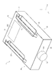
図1は、本実施形態に係るプロジェクター1を示す概要斜視図である。
本実施形態に係るプロジェクター1は、後述する照明装置31から出射される光を変調して画像情報に応じた画像を形成し、当該画像をスクリーン等の被投射面上に拡大投射する投射型表示装置である。
このプロジェクター1は、詳しくは後述するが、入射された光の光路を変更するシフト素子を備え、冷却装置は、後述する光変調装置の他、当該シフト素子を冷却する機能を有する。
このようなプロジェクター1は、図1に示すように、外装を構成する外装筐体2を備える。
[First Embodiment]
Hereinafter, a first embodiment of the present invention will be described with reference to the drawings.
[Projector external configuration]
FIG. 1 is a schematic perspective view showing a projector 1 according to the present embodiment.
The projector 1 according to the present embodiment modulates light emitted from a
Although described in detail later, the projector 1 includes a shift element that changes an optical path of incident light, and the cooling device has a function of cooling the shift element in addition to a light modulation device described later.
Such a projector 1 includes, as shown in FIG. 1, an
外装筐体2は、天面部21、底面部22、正面部23、背面部24及び左右の側面部25,26を有する略直方体形状に形成されている。
天面部21には、後述する光源装置31A,31Bを外装筐体2内に着脱するための開口部(図示省略)が形成され、当該開口部は、カバー部材212によって覆われている。
底面部22には、図示を省略するが、設置台等の設置面上に載置される際に、当該設置面と接触する脚部が設けられている。
正面部23には、後述する画像形成装置3を構成する投射光学装置35の一部が露出する開口部231が形成されている。
これらの他、図示を省略するが、右側の側面部26には、外装筐体2外の空気を内部に導入する導入口が形成され、左側の側面部25には、外装筐体2内の空気を外部に排出する排気口が形成されている。
The
An opening (not shown) for attaching and detaching the
Although not shown, the
An
In addition to these, although not shown, an inlet for introducing air outside the
[プロジェクターの内部構成]
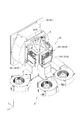
図2は、プロジェクター1の内部構成を示す模式図である。
プロジェクター1は、上記外装筐体2の他、図2に示すように、当該外装筐体2内に配置される画像形成装置3及び冷却装置4を備える。この他、図示を省略するが、プロジェクター1は、当該プロジェクター1を制御する制御装置、及び、当該プロジェクター1を構成する電子部品に電力を供給する電源装置を備える。
[Internal Configuration of Projector]
FIG. 2 is a schematic diagram illustrating an internal configuration of the projector 1.
As shown in FIG. 2, the projector 1 includes an image forming apparatus 3 and a
[画像形成装置の構成]
画像形成装置3は、上記制御装置から入力される画像情報に応じた画像を形成及び投射する。この画像形成装置3は、照明装置31、均一化装置32、色分離装置33、電気光学装置34、投射光学装置35及び光学部品用筐体36を備える。
これらのうち、光学部品用筐体36は、内部に照明光軸Axが設定された箱状筐体であり、照明装置31、均一化装置32及び色分離装置33は、光学部品用筐体36内における照明光軸Ax上の位置に配置される。また、電気光学装置34及び投射光学装置35は、光学部品用筐体36外に位置するものの当該照明光軸Axに応じて配置される。
[Configuration of Image Forming Apparatus]
The image forming apparatus 3 forms and projects an image according to the image information input from the control device. The image forming apparatus 3 includes a
Of these, the
照明装置31は、互いに対向配置される一対の光源装置31A,31Bと、当該一対の光源装置31A,31Bの間に配置される反射ミラー31Cと、を備える。
一対の光源装置31A,31Bは、それぞれ光源ランプ311及びリフレクター312と、これらを内部に収納する収納体313とを備える。そして、これら光源装置31A,31Bは、反射ミラー31Cに向けて光を出射する。
反射ミラー31Cは、光源装置31A,31Bから入射される光をそれぞれ同方向に反射させ、これにより、当該光を均一化装置32に入射させる。
The illuminating
Each of the pair of
The reflection mirror 31C reflects the light incident from the
均一化装置32は、照明装置31から出射された光束の中心軸に対する直交面内の照度を均一化する。この均一化装置32は、シネマフィルター321、第1レンズアレイ322、UVフィルター323、第2レンズアレイ324、偏光変換素子325及び重畳レンズ326を有する。
これらのうち、偏光変換素子325は、入射された光の偏光方向を一種類に揃えるものである。
色分離装置33は、均一化装置32から入射される光束を、赤(R)、緑(G)及び青(B)の3つの色光に分離する。この色分離装置33は、ダイクロイックミラー331,332、反射ミラー333〜336及びリレーレンズ337〜339を有する。
The equalizing
Among these, the
The
電気光学装置34は、分離された各色光を画像情報に応じて変調した後、変調された各色光を合成する。この電気光学装置34は、フィールドレンズ340、それぞれ色光毎に設けられる光変調装置としての液晶パネル341(赤、緑及び青用の液晶パネルを、それぞれ341R,341G,341Bとする)、入射側偏光板342及び出射側偏光板343と、光学補償板344と、1つの色合成装置345と、を有する。これらのうち、色合成装置345は、本発明の光合成装置に相当する。
シフト素子5は、色合成装置345により出射された光の光路を周期的にずらすことにより、投射画像の解像度を高めるものである。
これら電気光学装置34及びシフト素子5の構成については、詳しくは後述する。
The electro-
The
The configurations of the electro-
投射光学装置35は、色合成装置345により合成された光束(画像を形成する光束)を上記被投射面上に拡大投射する投射レンズである。このような投射光学装置35としては、鏡筒内に複数のレンズが配置された組レンズを採用できる。
The projection
なお、以下の図及び説明において、Z方向は、色合成装置345から出射された光の進行方向(投射方向)を示し、X方向及びY方向は、当該Z方向に直交し、かつ、互いに直交する方向を示す。これらのうち、Y方向は、平面視でZ方向が水平方向に沿うようにプロジェクター1が配置された場合に、鉛直方向とは反対方向である上方(すなわち、外装筐体2の底面部22から天面部21に向かう方向)を示し、X方向は、Z方向側(光の進行方向側)から見て左から右に向かう方向を示す。
In the following drawings and description, the Z direction indicates the traveling direction (projection direction) of the light emitted from the
[電気光学装置の構成]
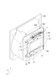
図3は、電気光学装置34及び冷却装置4をX方向側から見た斜視図であり、図4は、電気光学装置34及び冷却装置4をY方向側から見た平面図である。なお、図3及び図4においては、フィールドレンズ340が取り外された状態の電気光学装置34を示している。
電気光学装置34の構成要素のうち、各液晶パネル341(341R,341G,341B)、出射側偏光板343及び光学補償板344は、保持部材によって色合成装置345に取り付けられ、これらは、図3及び図4に示すように、一体化されたプリズムユニットを構成する。
このプリズムユニットを構成する色合成装置345は、略四角柱のクロスダイクロイックプリズムにより構成される。この色合成装置345は、6つの面3451〜3456を備える。これらのうち、色合成装置345のY方向側の面3451、及び、Y方向側とは反対側の面3452には、プリズムベース347U,347L(図3及び図11参照)が当接されて当該色合成装置345が支持される。
[Configuration of electro-optical device]
FIG. 3 is a perspective view of the electro-
Among the components of the electro-
The
また、色合成装置345のX方向側の面3453、X方向側とは反対側の面3454、及びZ方向側とは反対側の面3455が、それぞれ赤、青及び緑の変調光の入射面であり、Z方向側の面3456が出射面である。これら各入射面(面3453〜3455)に対向するように液晶パネル341R,341G,341Bが保持部材346(赤色用保持部材346R,緑色用保持部材346G,赤色用保持部材346B)によって保持され、これにより、液晶パネル341、入射側偏光板342、出射側偏光板343及び光学補償板344が一体化される。
Further, a
[シフト素子の構成]
図5は、固定部材360及びシフト素子5をZ方向とは反対方向側から見た斜視図である。
固定部材360は、光学部品用筐体36の一部を構成し、シフト素子5が固定される部位である。この固定部材360は、光学部品用筐体36において、投射光学装置35に対向する位置に配置される。この固定部材360のZ方向とは反対方向側の面3601には、図5に示すように、シフト素子5が固定される。具体的に、シフト素子5は、固定部材360に固定されることにより、色合成装置345及び投射光学装置35の間に配置された状態で固定される。
[Structure of shift element]
FIG. 5 is a perspective view of the fixing
The fixing
図6は、シフト素子5をZ方向側から見た平面図であり、図7は、シフト素子5をX方向とは反対方向側から見た側面図であり、図8は、シフト素子5の分解斜視図である。
シフト素子5は、本発明の光路変更素子に相当し、当該シフト素子5に入射され、当該シフト素子5から出射される光の光路を当該シフト素子5が揺動することにより変更(シフト)させる機能を有する。このようなシフト素子5は、図5〜図8に示すように、光学部材51、枠部52、永久磁石53、第1フレーム54、第2フレーム55及び一対のコイル保持部56,57を備える。
これらのうち、光学部材51は、透光性を有する透光性部材により構成され、本実施形態では、矩形板状のガラスにより構成される。
6 is a plan view of the
The
Among these, the
[枠部の構成]
枠部52は、光学部材51及び永久磁石53を保持する機能を有する。この枠部52は、図5に示すように、4つの角部CR1〜CR4を有する矩形板状に構成される。この枠部52の略中央部分には、上記光学部材51が嵌め込まれる開口部521が形成されている。また、枠部52の開口部521のY方向側の位置、及び、Y方向とは反対方向側の位置のそれぞれには、永久磁石53が嵌め込まれる嵌合溝522,523が形成されている。これら嵌合溝522,523のうち、嵌合溝522は、嵌合溝523よりもX方向とは反対方向側に形成されている。
[Configuration of frame part]
The
また、枠部52における嵌合溝522のY方向側で、かつ、X方向とは反対方向側の端縁には、Z方向に向けて突出する位置決め突起524が形成され、枠部52における嵌合溝523のY方向とは反対方向側でかつX方向側の端縁には、Z方向に向けて突出する位置決め突起525が形成されている。更に、枠部52のZ方向とは反対方向側の面には、これら位置決め突起524,525のそれぞれに対応する位置に、Z方向とは反対方向に向けて突出する位置決め突起526,527が形成されている。
換言すると、Y方向側の位置決め突起524,526は、枠部52の4つの角部CR1〜CR4のうち、角部CR3近傍に形成され、Y方向とは反対方向側の位置決め突起525,527は、当該角部CR3の対角となる角部CR2近傍に形成されている。
永久磁石53は、図8に示すように、角柱状に形成される。永久磁石53(永久磁石531)は、嵌合溝522に嵌合され、永久磁石53(永久磁石532)は、嵌合溝523に嵌合される。このようにして永久磁石531,532は、枠部52に固定される。
Further, a
In other words, the positioning
The
[第1フレームの構成]
第1フレーム54は、枠部52のZ方向とは反対方向側に配置され、当該枠部52を第2フレーム55とともに挟持する機能を有する。この第1フレーム54は、矩形板状に形成され、当該第1フレーム54の略中央部分には、開口部541が形成されている。この開口部541は、上記光学部材51と略同形状に形成される。これにより、開口部541から入射された光は、光学部材51に入射される。
また、第1フレーム54のY方向側で、かつ、X方向とは反対方向側の端縁には、貫通孔542が形成され、第1フレーム54のY方向とは反対方向側で、かつ、X方向側の端縁には、貫通孔543が形成されている。貫通孔542には、上記枠部52の位置決め突起524がそれぞれ挿入され、貫通孔543には、位置決め突起525がそれぞれ挿入される。
[Configuration of First Frame]
The
In addition, a through
[第2フレームの構成]
第1フレーム54は、枠部52のZ方向側に配置され、当該枠部52を第1フレーム54とともに挟持する機能を有する。この第2フレーム55は、矩形板状に形成され、当該第2フレーム55の略中央部分には、開口部551が形成されている。この開口部551は、上記光学部材51と略同形状に形成される。
また、第2フレーム55のY方向側で、かつ、X方向とは反対方向側の端縁には、貫通孔552が形成され、第2フレーム55のY方向とは反対方向側で、かつ、X方向側の端縁には、貫通孔553が形成されている。この貫通孔552には、上記枠部52の位置決め突起526が挿通され、貫通孔553には、位置決め突起527が挿通される。
[Configuration of Second Frame]
The
Further, a through
更に、第2フレーム55は、それぞれの角部から第2フレーム55の外側に延出する延出部554〜557を備える。これら延出部554〜557には、それぞれねじS1が挿通する貫通孔5541,5551,5561,5571が形成されている。これらねじS1が固定部材360に螺合することにより、シフト素子5は、図5に示すように、固定部材360に固定される。
このような構成により、第1フレーム54及び第2フレーム55は、枠部52を挟持する。なお、枠部52、第1フレーム54及び第2フレーム55は、本発明の保持部に相当する。
Further, the
With such a configuration, the
[コイル保持部の構成]
一対のコイル保持部56及び一対のコイル保持部57は、内部に本発明のコイルに相当する空芯コイルCLを備える。この空芯コイルCLは、当該空芯コイルCLに電力が供給されることにより、永久磁石53を変位させ、ひいては、シフト素子5を変位させる磁力を発生させる。これらのうち、一対のコイル保持部56は、第1フレーム54に固定されるコイル保持部561と、第2フレーム55に固定されるコイル保持部562とを備える。
これらコイル保持部561,562のそれぞれには、孔部5611,5621が形成されている。この孔部5611には、枠部52の位置決め突起524が第1フレーム54の貫通孔542を介して嵌まり込む。一方、孔部5621には、枠部52の位置決め突起526が第2フレーム55の貫通孔552を介して嵌まり込む。これにより、第1フレーム54にコイル保持部561が固定され、第2フレーム55にコイル保持部562が固定される。
[Configuration of coil holding unit]
The pair of
一方、一対のコイル保持部57は、第1フレーム54に固定されるコイル保持部571と、第2フレーム55に固定されるコイル保持部572とを備える。これらコイル保持部571,572のそれぞれには、孔部5711,5721が形成されている。この孔部5711には、枠部52の位置決め突起525が第1フレーム54の貫通孔543を介して嵌まり込む。一方、孔部5721には、枠部52の位置決め突起527が第2フレーム55の貫通孔553を介して嵌まり込む。これにより、第1フレーム54にコイル保持部571が固定され、第2フレーム55にコイル保持部572が固定される。
なお、一対のコイル保持部56、一対のコイル保持部56が備える空芯コイルCL、及び永久磁石531は、本発明の一方の揺動部材に相当し、一対のコイル保持部57、一対のコイル保持部57が備える空芯コイルCL及び永久磁石532は、本発明の他方の搖動部材に相当する。
On the other hand, the pair of
The pair of
このように、一対のコイル保持部56におけるコイル保持部561とコイル保持部562は、X方向とは反対方向側でY方向側の角部CR3近傍で、かつ、重なる位置及び向きに配置される。一方、一対のコイル保持部57におけるコイル保持部571とコイル保持部572は、シフト素子5をZ方向に沿って見た場合に、X方向側でY方向とは反対方向側の角部CR2近傍で、かつ、重なる位置及び向きに配置される。換言すると、固定部材360に固定されたシフト素子5をZ方向とは反対方向側から見て、一対のコイル保持部56は、液晶パネル341B側に配置され、一対のコイル保持部57は、液晶パネル341R側に配置される。
なお、上記枠部52、第1フレーム54、第2フレーム55、一対のコイル保持部56及び一対のコイル保持部57は、熱伝導性を有する金属により構成され、本実施形態では、アルミニウムにより構成されている。これにより、空芯コイルCLの温度が上昇した場合に、枠部52、第1フレーム54、第2フレーム55、一対のコイル保持部56及び一対のコイル保持部57コイル保持部56,57のそれぞれに当該空芯コイルCLの熱が伝導する。
As described above, the
The
また、上記コイル保持部561,562,571,572のそれぞれには、固定部材360に取り付けられた電力供給部3602が接続される(図5参照)。この電力供給部3602は、それぞれのコイル保持部561,562,571,572を介して空芯コイルCLに電力を供給することにより、永久磁石531,532を変位させ、ひいては、シフト素子5を変位させる磁力を発生させる。
具体的に、枠部52に取り付けられた永久磁石531,532が変異すると、シフト素子5は、図6に示す回動角L1に沿って固定部材360の面3601に対して接近及び離間する方向に移動することにより、枠部52の開口部521に嵌めこまれた光学部材51の角度が変更される。
換言すると、コイル保持部561,562,571,572のそれぞれに電力を供給することにより、光学部材51に入射され、当該光学部材51から出射される光の光路を変更することができる。
A
Specifically, when the
In other words, by supplying power to each of the
[冷却装置の構成]
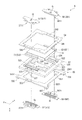
図9は、冷却装置4をY方向側から見た斜視図であり、図10は、冷却装置4をY方向側から見た平面図である。
冷却装置4は、冷却気体を送風して、液晶パネル341(341R,341G,341B)及びシフト素子5を冷却する機能を有する。この冷却装置4は、図9及び図10に示すように、冷却ファン41(液晶パネル341R,341G,341Bのそれぞれに対応する冷却ファンを冷却ファン41R,41G,41Bとする)と、ダクト部材42と、を備える。これらのうち、冷却ファン41は、当該冷却ファン41の周囲の冷却気体を吸引し、ダクト部材42を介して各液晶パネル341及びシフト素子5に冷却気体を供給する。
なお、この冷却ファン41は、シロッコファンにより構成されている。しかしながら、これに限らず、冷却ファン41は、軸流ファンにより構成されていてもよい。
[Configuration of cooling device]
FIG. 9 is a perspective view of the
The
The cooling
[ダクト部材の構成]
ダクト部材42は、各冷却ファン41から送出された冷却気体を、それぞれ対応する液晶パネル341、偏光板342,343及び光学補償板344の他、シフト素子5に導風する。このダクト部材42は、第1ダクト部43、第2ダクト部44、第3ダクト部45、及び接続部46を備える。
[Configuration of duct member]
The
[第1ダクト部の構成]
第1ダクト部43は、冷却ファン41Rからの冷却気体を液晶パネル341R及びシフト素子5におけるコイル保持部57に供給させる機能を有する。この第1ダクト部43は、分岐部431と、当該分岐部431によって分岐された一部の冷却気体を赤色用の液晶パネル341Rに送出する送出口432と、分岐された他の一部の冷却気体をシフト素子5のコイル保持部57に送出する送出口433と、を有する。
第1ダクト部43のX方向側の端部434は、冷却ファン41Rの吐出口に接続されている。また、第1ダクト部43の突出部435は、Y方向に延びる形状であり、当該突出部435のY方向側の端部には、上記送出口432が形成されている。この突出部435のY方向とは反対方向側の端部には、整流部436が設けられている。この整流部436は、略円弧状に形成され、冷却ファン41Rからの冷却気体をスムーズにY方向に向けて流通させる機能を有する。
また、送出口432は、上記液晶パネル341Rに対応する位置に配置されている。これにより、当該送出口432を介して冷却気体が液晶パネル341Rに向けて流通される。
[Configuration of First Duct Section]
The
An
The
また、第1ダクト部43は、図9及び図10に示すように、分岐部431からZ方向側に延出する延出部437を有する。この延出部437には、上記送出口433が形成されている。この延出部437のZ方向とは反対方向側の面4371には、開口部4372が形成されている。この開口部4372には、上記冷却ファン41Rから供給された冷却気体の一部が流通する。すなわち、分岐部431は、上記面4371及び開口部4372により構成される。
また、送出口433は、本発明の送出口に相当し、上記シフト素子5のコイル保持部57に対向する位置に配置される。
Further, as shown in FIGS. 9 and 10, the
The
[第2ダクト部の構成]
第2ダクト部44は、冷却ファン41Gからの冷却気体を液晶パネル341Gに供給させる機能を有する。この第2ダクト部44は、冷却気体を緑色用の液晶パネル341Gに送出する送出口442を有する。
この第2ダクト部44のZ方向とは反対方向側の端部444は、冷却ファン41Gの吐出口に接続されている。また、第2ダクト部44の突出部445には、上記送出口442が形成されている。この突出部445のY方向とは反対方向側の端部には、整流部446が設けられている。この整流部446は、略円弧状に形成され、冷却ファン41Gからの冷却気体をスムーズにY方向に向けて流通させる機能を有する。
また、送出口442は、上記液晶パネル341Gに対応する位置に配置されている。これにより、当該送出口442を介して冷却気体が液晶パネル341Gに向けて流通される。
[Configuration of Second Duct Section]
The
The
The
[第3ダクト部の構成]
第3ダクト部45は、冷却ファン41Bからの冷却気体を液晶パネル341B及びシフト素子5におけるコイル保持部56に供給させる機能を有する。この第3ダクト部45は、分岐部451と、当該分岐部451によって分岐された一部の冷却気体を青色用の液晶パネル341Bに送出する送出口452と、分岐された他の一部の冷却気体をシフト素子5のコイル保持部56に送出する送出口453と、を有する。
第3ダクト部45のZ方向とは反対方向側の端部454は、冷却ファン41Bの吐出口に接続されている。また、第3ダクト部45の突出部455は、Y方向に延びる形状であり、当該突出部455のY方向側の端部には、上記送出口452が形成されている。この突出部455のY方向とは反対方向側の端部には、整流部456が設けられている。この整流部456は、略円弧状に形成され、冷却ファン41Bからの冷却気体をスムーズにY方向に向けて流通させる機能を有する。
また、送出口452は、上記液晶パネル341Bに対応する位置に配置されている。これにより、当該送出口452を介して冷却気体が液晶パネル341Bに向けて流通される。
[Configuration of Third Duct Section]
The
The
The
また、第3ダクト部45は、図9及び図10に示すように、分岐部451からZ方向側に延出する延出部457を有する。この延出部457には、上記送出口453が形成されている。この延出部457のZ方向とは反対方向側の面4571には、開口部4572が形成されている。この開口部4572には、上記冷却ファン41Bから供給された冷却気体の一部が流通する。すなわち、分岐部451は、上記面4571及び開口部4572により構成される。
また、送出口453は、本発明の送出口に相当し、上記シフト素子5のコイル保持部56に対向する位置に配置される。
The
The
[冷却気体の流通方向]
図11は、電気光学装置34及び冷却装置4を図4に示す破線A1−A1にて切断した断面を示す断面図であり、図12は、電気光学装置34及び冷却装置4を図4に示す破線B1−B1にて切断した断面を示す断面図である。
上記冷却ファン41Gから送出された冷却気体は、図11及び図12に示すように、第2ダクト部44を介して送出口442からY方向に向けて送出され、液晶パネル341Gに供給される。
[Cooling gas flow direction]
11 is a cross-sectional view showing a cross section of the electro-
As shown in FIGS. 11 and 12, the cooling gas sent from the cooling
冷却ファン41Rから送出された冷却気体は、図11に示すように、第1ダクト部43内に導入される。この冷却気体のうち、分岐部431にて分岐された一部の冷却気体は、送出口432からY方向に向けて送出され、液晶パネル341Rに供給される。一方、分岐部431にて分岐された他の一部の冷却気体は、延出部437に流通し、当該延出部437に形成された送出口433からY方向に向けて送出され、シフト素子5におけるX方向側の領域に供給される。
ここで、延出部437のZ方向側の端部には、図11に示すように、Z方向に向けて傾斜する整流部4373が形成されている。このため、延出部437を流通する冷却気体は、送出口433から送出される際に、Z方向側に広がって送出される。具体的に、送出口433から送出される冷却気体は、シフト素子5のZ方向側の面及びZ方向とは反対方向側の面に流通される。更に詳述すると、送出口433から送出された冷却気体は、コイル保持部571のZ方向とは反対方向側の面及びコイル保持部572のZ方向側の面に流通される。
The cooling gas sent from the cooling
Here, a rectifying
冷却ファン41Bから送出された冷却気体は、図12に示すように、第3ダクト部45内に導入される。この冷却気体のうち、分岐部451にて分岐された一部の冷却気体は、送出口452からY方向に向けて送出され、液晶パネル341Bに供給される。一方、分岐部451にて分岐された他の一部の冷却気体は、延出部457に流通し、当該延出部457に形成された送出口453からY方向に向けて送出され、シフト素子5におけるX方向側の領域に供給される。
ここで、延出部457のZ方向側の端部には、図12に示すように、Z方向に向けて傾斜する整流部4573が形成されている。このため、延出部457を流通する冷却気体は、送出口453から送出される際に、Z方向側に広がって送出される。具体的に、送出口453から送出される冷却気体は、シフト素子5のZ方向側の面及びZ方向とは反対方向側の面に流通される。更に詳述すると、送出口453から送出された冷却気体は、コイル保持部571のZ方向とは反対方向側の面及びコイル保持部572のZ方向側の面に流通される。
The cooling gas sent from the cooling
Here, a rectifying
このようにしてシフト素子5におけるX方向側の領域、及び、X方向側とは反対側の領域に流通した冷却気体は、それぞれコイル保持部56,57に沿って流通することにより、これらコイル保持部56,57(特に空芯コイルCL)を冷却する他、当該コイル保持部56,57により挟まれる永久磁石53を冷却する。このようにしてシフト素子5が冷却され、当該シフト素子5の駆動が安定化される。
In this way, the cooling gas flowing in the region on the X direction side of the
[第1実施形態の効果]
以上説明した本実施形態に係るプロジェクター1は、以下の効果がある。
複数の冷却対象である液晶パネル341及びシフト素子5に冷却気体を供給できるので、液晶パネル341の温度が上昇することを抑制できる。また、冷却装置4によりシフト素子5が冷却されるので、液晶パネル341から入射された光により当該シフト素子5の温度が上昇することを抑制できる。
[Effects of First Embodiment]
The projector 1 according to the embodiment described above has the following effects.
Since the cooling gas can be supplied to the
色合成装置345と投射光学装置35との間にシフト素子5が配置されるので、当該シフト素子5が冷却される際に、当該シフト素子5とともに、色合成装置345も冷却できる。従って、色合成装置345から入射された光により当該シフト素子5の温度が上昇することを抑制できる。
Since the
液晶パネル341に冷却気体を流通させるダクト部材42が送出口433,453を有しているので、シフト素子5を冷却する冷却装置を別に設ける必要がない。これによれば、冷却装置4の小型化を図ることができ、ひいては、プロジェクター1を小型化できる。
Since the
ここで、永久磁石53を挟んで配置される一対の空芯コイルCLに電力が供給されると、永久磁石53を変位させ、ひいては、シフト素子5を変位させる磁力を発生させるとともに、当該空芯コイルCLの温度が上昇する。このように、空芯コイルCLの温度が上昇すると、磁力を発生させる空芯コイルCLの磁力が弱まることがある。
これに対し、本実施形態によれば、シフト素子5に冷却気体が供給されるので、シフト素子5、すなわち、シフト素子5が備える一対の空芯コイルCLの温度が上昇することを抑制できる。従って、シフト素子5に設けられた空芯コイルCLの磁力の低下を抑制できるので、当該シフト素子5の駆動を安定化できる。
Here, when electric power is supplied to the pair of air-core coils CL disposed with the
On the other hand, according to the present embodiment, since the cooling gas is supplied to the
シフト素子5の保持部を構成する第1フレーム54及び第2フレーム55に一対のコイル保持部56及び一対のコイル保持部57により空芯コイルCLが保持された状態で固定され、当該コイル保持部56,57に冷却気体の少なくとも一部が流通されるので、確実にコイル保持部56,57を冷却できる。従って、コイル保持部56,57を冷却することにより、当該コイル保持部56,57に保持される空芯コイルCLを冷却し、当該空芯コイルCLの温度が上昇することを抑制できる。
The air-core coil CL is fixed to the
色合成装置345を挟んで互いに反対側に配置された液晶パネル341R,341Bに応じた2つのダクト部43,45を介して冷却気体を当該液晶パネル341R,341B及びシフト素子5に供給できる。すなわち、2つの送出口433,453からシフト素子5に冷却気体が供給されるので、確実にシフト素子5を冷却できる。また、シフト素子5に冷却気体を流通させるダクトを更に設けることなく液晶パネル341及びシフト素子5に冷却気体を供給できるので、冷却装置4の小型化、ひいては、プロジェクター1を小型化できる。
Cooling gas can be supplied to the
一方の揺動部材を構成する空芯コイルCL、一対のコイル保持部56及び永久磁石531と一方の液晶パネル341Bとの位置が近接し、他方の揺動部材を構成する空芯コイルCL、一対のコイル保持部57及び永久磁石532と他方の液晶パネル341Rとの位置が近接する。このため、対向して配置される液晶パネル341R,341Bのそれぞれと上記それぞれの揺動部材の位置が近いので、当該近接して配置される液晶パネル341R,341Bに対応するダクト部43,45から揺動部材に冷却気体を流通させる分岐部431,451の構成を簡易にできる。また、当該ダクト部43,45の分岐部431,451から送出口433,453までの距離を短くできるので、当該ダクト部43,45を流通する冷却気体の流通速度の低下を抑制できる。従って、より確実にシフト素子5を冷却できる。
The air core coil CL constituting one swing member, the pair of
[第2実施形態]
次に、本発明の第2実施形態について説明する。
本実施形態に係るプロジェクターは、上記プロジェクター1と同様の構成を備えるが、電気光学装置を構成するシフト素子の形状が異なる点で、上記プロジェクター1と相違する。なお、以下の説明では、既に説明した部分と同一又は略同一である部分については、同一の符号を付して説明を省略する。
[Second embodiment]
Next, a second embodiment of the present invention will be described.
The projector according to the present embodiment has a configuration similar to that of the projector 1, but differs from the projector 1 in that the shape of a shift element constituting the electro-optical device is different. In the following description, portions that are the same or substantially the same as the portions already described are denoted by the same reference numerals, and description thereof is omitted.
図13は、本実施形態に係るプロジェクターのシフト素子5Aを示す斜視図である。
シフト素子5Aは、本発明の光路変更素子に相当し、入射された光の光路を変更する機能を有する。このようなシフト素子5Aは、図13に示すように、光学部材51、枠部52、永久磁石(図示省略)、第1フレーム54、第2フレーム55、一対のコイル保持部56A及び一対のコイル保持部57を備える。本実施形態では、コイル保持部56Aの構成のみ異なるので、以下に当該コイル保持部56Aについてのみ詳しく説明する。
FIG. 13 is a perspective view showing a
The
一対のコイル保持部56Aは上記コイル保持部56と同様に、内部に空芯コイルCLを有し、熱伝導性を有するアルミニウムにより構成される。また、一対のコイル保持部56Aのうち、Z方向とは反対方向側のコイル保持部561Aは、図13に示すように、略L字状に構成される。具体的に、コイル保持部561Aは、第1フレーム54のX方向とは反対方向側の辺縁に沿って、送出口453側、すなわち、Y方向とは反対方向側に延出する延出部56A1を備える。この構成により、コイル保持部561Aの放熱面積は、他のコイル保持部562,571,572の放熱面積より大きくなる。
このようなコイル保持部561Aに対して、送出口453から冷却気体が送出されると、当該コイル保持部561Aの延出部56A1のZ方向とは反対方向側の面に沿って冷却気体が流通され、当該コイル保持部561Aが冷却される。
The pair of
When the cooling gas is sent from the
[第2実施形態の効果]
以上説明した本実施形態に係るプロジェクターは、上記プロジェクター1と同様の効果を奏する他、以下の効果がある。
送出口433からコイル保持部57までの距離と比較して、送出口453からコイル保持部56までの距離は大きい。また、コイル保持部57を冷却し、温度上昇した冷却気体の一部がコイル保持部56に流通する可能性がある。これらにより、コイル保持部56の冷却効率は、コイル保持部57の冷却効率より低くなることが想定される。
ここで、コイル保持部561Aが延出部56A1を有するので、当該延出部56A1を備えたコイル保持部561Aの放熱面積は、当該延出部56A1を有しない上記コイル保持部561の放熱面積より大きくなる。これによれば、コイル保持部561A(延出部56A1)に冷却気体が供給されるので、より確実にコイル保持部561Aを冷却できる。従って、コイル保持部561Aに保持された空芯コイルCLを確実に冷却し、当該空芯コイルCLの温度が上昇することを抑制できる。
[Effect of Second Embodiment]
The projector according to the present embodiment described above has the following effects in addition to the same effects as the projector 1 described above.
The distance from the
Here, since the
[第3実施形態]
次に、本発明の第3実施形態について説明する。
本実施形態に係るプロジェクターは、上記プロジェクター1と同様の構成を備えるが、電気光学装置を構成するシフト素子の形状が異なる点で、上記プロジェクター1と相違する。なお、以下の説明では、既に説明した部分と同一又は略同一である部分については、同一の符号を付して説明を省略する。
[Third embodiment]
Next, a third embodiment of the present invention will be described.
The projector according to the present embodiment has a configuration similar to that of the projector 1, but differs from the projector 1 in that the shape of a shift element constituting the electro-optical device is different. In the following description, portions that are the same or substantially the same as the portions already described are denoted by the same reference numerals, and description thereof is omitted.
図14は、本実施形態に係るプロジェクターのシフト素子5Bを示す斜視図である。
シフト素子5Bは、本発明の光路変更素子に相当し、入射された光の光路を変更する機能を有する。このようなシフト素子5Bは、図14に示すように、光学部材51、枠部52、永久磁石(図示省略)、第1フレーム54、第2フレーム55、一対のコイル保持部56B及び一対のコイル保持部57Bを備える。本実施形態では、コイル保持部56B,57Bの構成のみ異なるので、以下に当該コイル保持部56B,57Bについてのみ詳しく説明する。
FIG. 14 is a perspective view showing a
The
一対のコイル保持部56B及び一対のコイル保持部57Bは、上記コイル保持部56と同様に、内部に空芯コイルCLを有し、熱伝導性を有するアルミニウムにより構成される。また、これらコイル保持部561A,561Bのそれぞれは、本発明の放熱部に相当する複数の矩形板状のフィン56B1を備える。一方、コイル保持部571B,572Bのそれぞれも、複数の矩形板状のフィン57B1を備える。この構成により、一対のコイル保持部56B,57Bの放熱面積は、上記第1実施形態に係る一対のコイル保持部56,57の放熱面積より大きくなる。
このような一対のコイル保持部56B,57Bに対して、送出口433,453から冷却気体が送出されると、当該一対のコイル保持部56B,57Bの複数のフィン56B1,57B1の間を冷却気体が流通され、当該一対のコイル保持部56B,57Bが冷却される。
The pair of
When the cooling gas is sent from the
[第3実施形態の効果]
以上説明した本実施形態に係るプロジェクターは、上記プロジェクター1と同様の効果を奏する他、以下の効果がある。
一対のコイル保持部56B及び一対のコイル保持部57Bが放熱部としてフィン56B1,57B1を備えるので、一対のコイル保持部56B及び一対のコイル保持部57Bの放熱量は、当該フィン56B1,57B1を有していないコイル保持部56,57の放熱量より大きくなる。これによれば、一対のコイル保持部56B及び一対のコイル保持部57Bのフィン56B1,57B1に冷却気体が供給されることにより、より確実に一対のコイル保持部56B及び一対のコイル保持部57Bを冷却できる。従って、一対のコイル保持部56B及び一対のコイル保持部57Bに保持された空芯コイルCLを確実に冷却し、当該空芯コイルCLの温度が上昇することを抑制できる。
[Effects of Third Embodiment]
The projector according to the present embodiment described above has the following effects in addition to the same effects as the projector 1 described above.
Since the pair of
[実施形態の変形]
本発明は、上記各実施形態に限定されるものではなく、本発明の目的を達成できる範囲での変形、改良等は本発明に含まれるものである。
上記各実施形態において、冷却装置4は、第1〜第3ダクト部43〜45のそれぞれに接続される冷却ファン41R,41G,41Bを備えることとした。しかしながら、本発明は、これに限らない。例えば、冷却ファン41は、1つであってもよいし、2つであってもよい。この場合、第1〜第3ダクト部43〜45に冷却気体が供給されれば、第1〜第3ダクト部43〜45はどのような形状であってもよい。
[Modification of Embodiment]
The present invention is not limited to the above embodiments, but includes modifications and improvements as long as the object of the present invention can be achieved.
In each of the above embodiments, the
上記各実施形態において、シフト素子5は、光学部材51、枠部52、永久磁石53、第1フレーム54、第2フレーム55及び一対のコイル保持部56,57を備えることとした。しかしながら、本発明は、これに限らない。例えば、第1フレーム54及び第2フレーム55は、一体となっていてもよい。また、一対のコイル保持部56及び一対のコイル保持部57を備えることとしたが、いずれか一方のみを備えることとしてもよい。
すなわち、コイル保持部56,57に保持される空芯コイルCLに電力が供給され、シフト素子5が揺動し、上記光学部材51に入射される光の光路を変更できれば、どのような構成であってもよい。
In each of the above embodiments, the
That is, as long as power is supplied to the air-core coil CL held by the
上記各実施形態において、空芯コイルCLは、各コイル保持部56,57に保持されることとした。しかしながら、本発明は、これに限らない。例えば、空芯コイルCLが直接第1フレーム54及び第2フレーム55に固定される構成であってもよい。
上記各実施形態において、色合成装置345は、クロスダイクロイックプリズムにより構成されていることとした。しかしながら、本発明は、これに限らない。例えば、色合成装置345は、液晶パネル341から入射される光を合成できれば、どのような形状であってもよい。
In each of the above embodiments, the air-core coil CL is held by each of the
In the above embodiments, the
上記各実施形態では、一対のコイル保持部56は、第1フレーム54における角部CR3の近傍、すなわち、シフト素子5をZ方向とは反対方向側から見て、X方向とは反対方向側でY方向側の位置に配置され、一対のコイル保持部57は、第1フレーム54における角部CR2の近傍、すなわち、X方向側でY方向とは反対方向側の位置に配置されることとした。しかしながら、本発明は、これに限らない。例えば、一対のコイル保持部56と一対のコイル保持部57の位置が逆であってもよい。この場合であっても、上記各実施形態のシフト素子5,5A,5Bのそれぞれと同様の効果を奏することができる。
In each of the above-described embodiments, the pair of
上記各実施形態において、分岐部431,451は、第1ダクト部43及び第3ダクト部45にのみ設けられることとした。しかしながら、本発明は、これに限らない。例えば、第2ダクト部44に分岐部を設け、当該分岐部からシフト素子5に対して冷却気体を供給するようにしてもよい。この場合、色合成装置345を固定するプリズムベース347Lを設けることなく、接続部46に代えて送出口を構成するようにすればよい。これによれば、第1〜第3ダクト部43〜45のそれぞれを流通する冷却気体から分岐された冷却気体がシフト素子5の略全領域に供給されるので、シフト素子5を更に確実に冷却できる。
In the above embodiments, the
上記各実施形態において、一対のコイル保持部56,57,56A,56B,57Bは、空芯コイルCLを保持することとした。しかしながら、本発明は、これに限らない。例えば、一対のコイル保持部56,57,56A,56B,57Bは、鉄心コイルを保持することとしてもよい。すなわち、電力が供給することで磁力を発生させることができるものであれば、コイルの形状及び種類は、どのようなものであってもよい。
In each of the above embodiments, the pair of
上記各実施形態において、上記枠部52、第1フレーム54、第2フレーム55及び一対のコイル保持部56,57,56A,56B,57Bは、アルミニウムにより構成されていることとした。しかしながら、本発明は、これに限らない。例えば、上記枠部52、第1フレーム54、第2フレーム55及び一対のコイル保持部56,57,56A,56B,57Bは、アルミニウムに限らず、熱伝導性を有していればどのような素材により構成されてもよい。
In the above embodiments, the
上記各実施形態において、突出部435,445,455のY方向とは反対方向側の端部に整流部436,446,456が設けられていることとした。しかしながら、本発明は、これに限らない。例えば、当該整流部436,446,456は、外装筐体2の内面であってもよく、この場合には、ダクト部材42が当該内面に取り付けられることによって、各ダクト部が形成されることとなる。
In each of the above embodiments, the rectifying
上記第2実施形態において、コイル保持部561Aが延出部56A1を備えることとした。しかしながら、本発明は、これに限らない。例えば、コイル保持部562も当該コイル保持部561Aと同様に延出部を備えることとしてもよい。更に、コイル保持部571,572も同様に延出部を備えることとしてもよい。加えて、これら延出部を備えたコイル保持部561A,562,571,572のそれぞれに、上記第3実施形態に係るフィン56B1,57B1を更に設けるようにしてもよい。
In the second embodiment, the
上記第3実施形態において、一対のコイル保持部56B,57Bのいずれもがフィン56B1,57B1を備えたヒートシンク形状であることとした。しかしながら、本発明は、これに限らない。例えば、第1フレーム54に取り付けられるコイル保持部561B,571Bにのみフィン56B1,57B1を設けるようにしてもよいし、第2フレーム55に取り付けられるコイル保持部562B,572Bにのみフィン56B1,57B1を設けるようにしてもよい。すなわち、コイル保持部561B,562B,571B,572Bのいずれかにフィン56B1,56B2が設けられていればよい。
また、フィン56B1,57B1の形状は、矩形板状に限らず、どのような形状であってもよいし、コイル保持部561B,562B,571B,572Bごとに異なる形状のフィンが設けられるようにしてもよい。要するに、コイル保持部561B,562B,571B,572Bの放熱面積が拡大すればよい。
In the third embodiment, each of the pair of
The shape of the fins 56B1 and 57B1 is not limited to a rectangular plate, but may be any shape. Different fins are provided for each of the
上記実施形態では、光変調装置として透過型の液晶パネル341(341R,341G,341B)を用いることとした。しかしながら、本発明は、これに限らない。例えば、透過型の液晶パネル341(341R,341G,341B)に代えて、反射型の液晶パネルを用いてもよい。この場合、色分離装置33を設けることなく、当該色合成装置345により、色分離及び色合成を実行するようにしてもよい。
In the above embodiment, the transmission type liquid crystal panel 341 (341R, 341G, 341B) is used as the light modulation device. However, the present invention is not limited to this. For example, a reflective liquid crystal panel may be used instead of the transmissive liquid crystal panel 341 (341R, 341G, 341B). In this case, color separation and color synthesis may be performed by the
上記実施形態では、プロジェクター1は、3つの液晶パネル341(341R,341G,341B)を備えることとしたが、本発明はこれに限らない。すなわち、2つ以下、あるいは、4つ以上の液晶パネルを用いたプロジェクターにも、本発明を適用可能である。
また、液晶パネルに代えて、DMD(デジタルマイクロミラーデバイス)等を用いてもよい。
In the above embodiment, the projector 1 includes the three liquid crystal panels 341 (341R, 341G, 341B), but the present invention is not limited to this. That is, the present invention is also applicable to a projector using two or less or four or more liquid crystal panels.
Further, a DMD (digital micromirror device) or the like may be used instead of the liquid crystal panel.
上記実施形態では、プロジェクター1は、一対の光源装置31A,31Bを備えることとした。しかしながら、本発明は、これに限らない。例えば、光源装置は1つであってもよいし4つであってもよい。
上記実施形態では、画像形成装置3の配置は、図2に示す配置とした。しかしながら、本発明は、これに限らない。例えば、上記画像形成装置を略L字型若しくは略U字型に配置することとしてもよい。
In the above embodiment, the projector 1 includes the pair of
In the above embodiment, the arrangement of the image forming apparatus 3 is the arrangement shown in FIG. However, the present invention is not limited to this. For example, the image forming apparatuses may be arranged in a substantially L shape or a substantially U shape.
1…プロジェクター、31…照明装置(光源)、341,341R,341B,341B…液晶パネル(光変調装置)、345…色合成装置(光合成装置)、3453,3454,3455…面(入射面)、3456…面(出射面)、35…投射光学装置、4…冷却装置、41,41B,41G,41R…冷却ファン、42…ダクト部材、43…第1ダクト部(ダクト)、431,451…分岐部、433,453…送出口、44…第2ダクト部(ダクト)、45…第3ダクト部(ダクト)、4371,4571…面(分岐部)、4372,4572…開口部(分岐部)、5,5A,5B…シフト素子、51…光学部材、52…枠部(保持部)、53,531,532…永久磁石(搖動部材)、54…第1フレーム(保持部)、55…第2フレーム(保持部)56,57,56A,56B…一対のコイル保持部(搖動部材)、561,562,571,572,561A,561B,562B,571B,572B…コイル保持部、56A1…延出部、56B1,57B1…フィン(放熱部)、CL…空芯コイル(一対のコイル、搖動部材)。 DESCRIPTION OF SYMBOLS 1 ... Projector, 31 ... Illumination device (light source), 341, 341R, 341B, 341B ... Liquid crystal panel (light modulation device), 345 ... Color synthesizing device (light synthesizing device), 3453, 3454, 3455 ... Surface (incident surface), 3456: Surface (outgoing surface), 35: Projection optical device, 4: Cooling device, 41, 41B, 41G, 41R: Cooling fan, 42: Duct member, 43: First duct portion (duct), 431, 451: Branch Parts, 433, 453 ... outlet, 44 ... second duct part (duct), 45 ... third duct part (duct), 4371, 4571 ... plane (branch part), 4372, 4572 ... opening part (branch part), 5, 5A, 5B: shift element, 51: optical member, 52: frame portion (holding portion), 53, 531, 532: permanent magnet (oscillating member), 54: first frame (holding portion), 55: second H Arms (holding portions) 56, 57, 56A, 56B: a pair of coil holding portions (oscillating members), 561, 562, 571, 572, 561A, 561B, 562B, 571B, 572B: coil holding portions, 56A1 ... extension Parts, 56B1, 57B1 ... fins (radiator), CL ... air-core coils (a pair of coils, swinging members).
Claims (12)
前記光源から出射された光を変調する光変調装置と、
前記光変調装置により変調された光を投射する投射光学装置と、
前記光変調装置と前記投射光学装置との間に配置され、前記光変調装置により変調された光が入射し、揺動により入射した光の光路を変更する光路変更素子と、
前記光変調装置及び前記光路変更素子を冷却する冷却装置と、
を備え、
前記光路変更素子は、
永久磁石と、
前記永久磁石により揺動されて入射された光の光路を変更する光学部材と、
前記光学部材及び前記永久磁石を保持する保持部と、
前記永久磁石を挟んで前記保持部に配置される一対のコイルと、
前記一対のコイルを保持して前記保持部に取り付けられるコイル保持部と、
を有し、
複数の前記光変調装置と、
前記複数の光変調装置により変調された光を合成して出射する光合成装置と、
を備え、
前記投射光学装置は、前記光合成装置から出射された光を投射し、
前記光路変更素子は、前記光合成装置と前記投射光学装置との間に配置され、
前記冷却装置は、
冷却気体を送出する冷却ファンと、
前記冷却ファンからの前記冷却気体を前記複数の光変調装置に流通させるダクト部材と、
を備え、
前記ダクト部材は、前記光路変更素子に向けて前記冷却気体を流通させる送出口を有し、
前記送出口は、前記コイル保持部に対向する位置に配置されていることを特徴とするプロジェクター。 Light source,
A light modulation device that modulates light emitted from the light source,
A projection optical device that projects light modulated by the light modulation device,
An optical path changing element disposed between the light modulation device and the projection optical device, the light modulated by the light modulation device being incident, and changing the optical path of the incident light by swinging,
A cooling device for cooling the light modulation device and the light path changing element,
With
The optical path changing element,
A permanent magnet,
An optical member that changes the optical path of light that has been rocked and incident by the permanent magnet,
A holding unit that holds the optical member and the permanent magnet,
A pair of coils disposed on the holding portion with the permanent magnet interposed therebetween,
A coil holding unit that holds the pair of coils and is attached to the holding unit;
Have a,
A plurality of the light modulation devices,
A light combining device that combines and emits light modulated by the plurality of light modulation devices,
With
The projection optical device projects light emitted from the photosynthesis device,
The optical path changing element is disposed between the light combining device and the projection optical device,
The cooling device,
A cooling fan for sending a cooling gas;
A duct member that allows the cooling gas from the cooling fan to flow through the plurality of light modulation devices,
With
The duct member has an outlet through which the cooling gas flows toward the optical path changing element,
The delivery port, the projector characterized that you have been placed at a position opposed to the coil holder.
前記光源から出射された光を変調する光変調装置と、
前記光変調装置により変調された光を投射する投射光学装置と、
前記光変調装置と前記投射光学装置との間に配置され、前記光変調装置により変調された光が入射し、揺動により入射した光の光路を変更する光路変更素子と、
前記光変調装置及び前記光路変更素子を冷却する冷却装置と、
を備え、
前記光路変更素子は、
永久磁石と、
前記永久磁石により揺動されて入射された光の光路を変更する光学部材と、
前記光学部材及び前記永久磁石を保持する保持部と、
前記永久磁石を挟んで前記保持部に配置される一対のコイルと、
前記一対のコイルを保持して前記保持部に取り付けられるコイル保持部と、
を有し、
複数の前記光変調装置と、
前記複数の光変調装置により変調された光を合成して出射する光合成装置と、
を備え、
前記投射光学装置は、前記光合成装置から出射された光を投射し、
前記光路変更素子は、前記光合成装置と前記投射光学装置との間に配置され、
前記冷却装置は、
冷却気体を送出する冷却ファンと、
前記冷却ファンからの前記冷却気体を前記複数の光変調装置に流通させるダクト部材と、
を備え、
前記ダクト部材は、前記光路変更素子に向けて前記冷却気体を流通させる送出口を有し、
前記コイル保持部は、前記送出口側に延出する延出部を有することを特徴とするプロジェクター。 Light source,
A light modulation device that modulates light emitted from the light source,
A projection optical device that projects light modulated by the light modulation device,
An optical path changing element disposed between the light modulation device and the projection optical device, the light modulated by the light modulation device being incident, and changing the optical path of the incident light by swinging,
A cooling device for cooling the light modulation device and the light path changing element,
With
The optical path changing element,
A permanent magnet,
An optical member that changes the optical path of light that has been rocked and incident by the permanent magnet,
A holding unit that holds the optical member and the permanent magnet,
A pair of coils disposed on the holding portion with the permanent magnet interposed therebetween,
A coil holding unit that holds the pair of coils and is attached to the holding unit;
Has,
A plurality of the light modulation devices,
A light combining device that combines and emits light modulated by the plurality of light modulation devices,
With
The projection optical device projects light emitted from the photosynthesis device,
The optical path changing element is disposed between the light combining device and the projection optical device ,
The cooling device,
A cooling fan for sending a cooling gas;
A duct member that allows the cooling gas from the cooling fan to flow through the plurality of light modulation devices,
With
The duct member has an outlet through which the cooling gas flows toward the optical path changing element,
The coil holding portion, the projector characterized by Rukoto that having a extension portion extending to said delivery port side.
前記ダクト部材は、前記冷却ファンからの冷却気体を、前記光変調装置に流通する冷却気体と前記送出口に流通する冷却気体とに分岐する分岐部を有することを特徴とするプロジェクター。 In the projector according to any one of claims 1 and 2 ,
The projector, wherein the duct member has a branching portion that branches the cooling gas from the cooling fan into a cooling gas flowing through the light modulation device and a cooling gas flowing through the outlet .
前記送出口は、前記光路変更素子の光入射側及び光出射側の両方に前記冷却気体を流通させ、
前記ダクト部材は、前記冷却ファンからの冷却気体を、前記光変調装置に流通する冷却気体と前記送出口に流通する冷却気体とに分岐する分岐部を有することを特徴とするプロジェクター。 In the projector according to any one of claims 1 and 2 ,
The sending port allows the cooling gas to flow through both the light incident side and the light emitting side of the optical path changing element ,
The projector, wherein the duct member has a branching portion that branches the cooling gas from the cooling fan into a cooling gas flowing through the light modulation device and a cooling gas flowing through the outlet .
前記コイル保持部は、放熱部を有し、
前記ダクト部材は、前記冷却ファンからの冷却気体を、前記光変調装置に流通する冷却気体と前記送出口に流通する冷却気体とに分岐する分岐部を有することを特徴とするプロジェクター。 In the projector according to any one of claims 1 and 2 ,
The coil holding unit has a heat radiating unit,
The duct member is a projector the cooling gas from the cooling fan, and wherein the Rukoto that having a branching portion that branches to the cooling gas flowing to said outlet and the cooling gas flowing to the light modulation device.
前記光源から出射された光を変調する光変調装置と、
前記光変調装置により変調された光を投射する投射光学装置と、
前記光変調装置と前記投射光学装置との間に配置され、前記光変調装置により変調された光が入射し、揺動により入射した光の光路を変更する光路変更素子と、
前記光変調装置及び前記光路変更素子を冷却する冷却装置と、
を備え、
前記光路変更素子は、
永久磁石と、
前記永久磁石により揺動されて入射された光の光路を変更する光学部材と、
前記光学部材及び前記永久磁石を保持する保持部と、
前記永久磁石を挟んで前記保持部に配置される一対のコイルと、
前記一対のコイルを保持して前記保持部に取り付けられるコイル保持部と、
を有し、
複数の前記光変調装置と、
前記複数の光変調装置により変調された光を合成して出射する光合成装置と、
を備え、
前記投射光学装置は、前記光合成装置から出射された光を投射し、
前記光路変更素子は、前記光合成装置と前記投射光学装置との間に配置され、
前記冷却装置は、
冷却気体を送出する冷却ファンと、
前記冷却ファンからの前記冷却気体を前記複数の光変調装置に流通させるダクト部材と、
を備え、
前記ダクト部材は、前記光路変更素子に向けて前記冷却気体を流通させる送出口を有し、
前記複数の光変調装置は、前記光合成装置を挟んで互いに対向する位置に配置される第1光変調装置及び第2光変調装置を含み、
前記ダクト部材は、前記第1光変調装置に前記冷却気体を流通させる第1ダクトと、前記第2光変調装置に前記冷却気体を流通させる第2ダクトと、を有し、
前記光路変更素子は、第1コイル保持部及び第2コイル保持部として2つのコイル保持部を有し、
前記第1ダクトは、前記送出口として、前記第1コイル保持部に対向する位置に配置される第1送出口を有し、
前記第2ダクトは、前記送出口として、前記第2コイル保持部に対向する位置に配置される第2送出口を有することを特徴とするプロジェクター。 Light source,
A light modulation device that modulates light emitted from the light source,
A projection optical device that projects light modulated by the light modulation device,
An optical path changing element disposed between the light modulation device and the projection optical device, the light modulated by the light modulation device being incident, and changing the optical path of the incident light by swinging,
A cooling device for cooling the light modulation device and the light path changing element,
With
The optical path changing element,
A permanent magnet,
An optical member that changes the optical path of light that has been rocked and incident by the permanent magnet,
A holding unit that holds the optical member and the permanent magnet,
A pair of coils disposed on the holding portion with the permanent magnet interposed therebetween,
A coil holding unit that holds the pair of coils and is attached to the holding unit;
Has,
A plurality of the light modulation devices,
A light combining device that combines and emits light modulated by the plurality of light modulation devices,
With
The projection optical device projects light emitted from the photosynthesis device,
The optical path changing element is disposed between the light combining device and the projection optical device,
The cooling device,
A cooling fan for sending a cooling gas;
A duct member that allows the cooling gas from the cooling fan to flow through the plurality of light modulation devices,
With
The duct member has an outlet through which the cooling gas flows toward the optical path changing element,
The plurality of light modulation devices include a first light modulation device and a second light modulation device arranged at positions facing each other with the light synthesis device interposed therebetween,
The duct member has a first duct for flowing the cooling gas through the first light modulation device, and a second duct for flowing the cooling gas through the second light modulation device,
The optical path changing element has two coil holding units as a first coil holding unit and a second coil holding unit,
The first duct has, as the outlet, a first outlet disposed at a position facing the first coil holding unit,
The projector , wherein the second duct has, as the outlet , a second outlet disposed at a position facing the second coil holding unit .
前記保持部は、前記光学部材が嵌め込まれる開口部を有し、
前記第1コイル保持部及び前記第2コイル保持部は、前記開口部を挟んで互いに対向する前記保持部の部位に配置され、かつ、前記第1光変調装置及び前記第2光変調装置が対向する第1方向において互いにずれて配置され、
前記第1送出口及び前記第2送出口は、前記第1方向において互いにずれて配置されていることを特徴とするプロジェクター。 The projector according to claim 6 ,
The holding unit has an opening into which the optical member is fitted,
The first coil holding portion and the second coil holding portion are arranged at portions of the holding portion facing each other with the opening interposed therebetween, and the first light modulation device and the second light modulation device face each other. Are displaced from each other in a first direction,
It said first outlet and said second delivery port is the projector characterized that you have been arranged offset to each other in the first direction.
前記光源から出射された光を変調する光変調装置と、
前記光変調装置により変調された光を投射する投射光学装置と、
前記光変調装置と前記投射光学装置との間に配置され、前記光変調装置により変調された光が入射し、揺動により入射した光の光路を変更する光路変更素子と、
前記光変調装置及び前記光路変更素子を冷却する冷却装置と、
を備え、
前記光路変更素子は、
永久磁石と、
前記永久磁石により揺動されて入射された光の光路を変更する光学部材と、
前記光学部材及び前記永久磁石を保持する保持部と、
前記永久磁石を挟んで前記保持部に配置される一対のコイルと、
前記一対のコイルを保持して前記保持部に取り付けられるコイル保持部と、
を有し、
複数の前記光変調装置と、
前記複数の光変調装置により変調された光を合成して出射する光合成装置と、
を備え、
前記投射光学装置は、前記光合成装置から出射された光を投射し、
前記光路変更素子は、前記光合成装置と前記投射光学装置との間に配置され、
前記冷却装置は、
冷却気体を送出する冷却ファンと、
前記冷却ファンからの前記冷却気体を前記複数の光変調装置に流通させるダクト部材と、
を備え、
前記ダクト部材は、前記光路変更素子に向けて前記冷却気体を流通させる送出口を有し、
前記光合成装置は、
前記複数の光変調装置を介した光が入射される3つの入射面と、
前記3つの入射面から入射され、合成された光が出射される1つの出射面と、
を有し、
前記ダクト部材は、前記複数の光変調装置のそれぞれに応じて設けられ、内部を流通する前記冷却気体を対応する前記光変調装置に送出する複数のダクトを有し、
前記複数のダクトのうち、前記光合成装置を挟んで互いに反対側に配置された光変調装置に対応するダクトは、内部を流通する前記冷却気体を分岐させ、前記送出口から当該冷却気体を送出させる分岐部を有することを特徴とするプロジェクター。 Light source,
A light modulation device that modulates light emitted from the light source,
A projection optical device that projects light modulated by the light modulation device,
An optical path changing element disposed between the light modulation device and the projection optical device, the light modulated by the light modulation device being incident, and changing the optical path of the incident light by swinging,
A cooling device for cooling the light modulation device and the light path changing element,
With
The optical path changing element,
A permanent magnet,
An optical member that changes the optical path of light that has been rocked and incident by the permanent magnet,
A holding unit that holds the optical member and the permanent magnet,
A pair of coils disposed on the holding portion with the permanent magnet interposed therebetween,
A coil holding unit that holds the pair of coils and is attached to the holding unit;
Has,
A plurality of the light modulation devices,
A light combining device that combines and emits light modulated by the plurality of light modulation devices,
With
The projection optical device projects light emitted from the photosynthesis device,
The optical path changing element is disposed between the light combining device and the projection optical device,
The cooling device,
A cooling fan for sending a cooling gas;
A duct member that allows the cooling gas from the cooling fan to flow through the plurality of light modulation devices,
With
The duct member has an outlet through which the cooling gas flows toward the optical path changing element,
The photosynthesis device,
Three incident surfaces on which light passing through the plurality of light modulators is incident;
One exit surface from which the three incident surfaces are incident and from which the combined light is emitted;
Has,
The duct member is provided in accordance with each of the plurality of light modulation devices, and has a plurality of ducts for sending the cooling gas flowing inside to the corresponding light modulation devices,
Among the plurality of ducts, the duct corresponding to the light modulation device arranged on the opposite side with respect to the photosynthesis device branches the cooling gas flowing inside, and sends the cooling gas from the outlet. A projector having a branch portion .
前記光路変更素子は、前記永久磁石及び前記一対のコイルを含む揺動部材を2つ有し、
前記光合成装置を挟んで互いに反対側に配置された光変調装置のうち、
一方の光変調装置側に一方の前記揺動部材が配置され、他方の光変調装置側に他方の前記揺動部材が配置され、
一方の前記揺動部材は、前記光学部材に対する光の入射方向側から見て、前記光学部材を挟んで他方の前記揺動部材の反対側となる位置に配置されることを特徴とするプロジェクター。 The projector according to claim 8 ,
The optical path changing element has two rocking members including the permanent magnet and the pair of coils,
Among the light modulation devices arranged on opposite sides of the photosynthesis device,
One of the rocking members is arranged on one light modulation device side, and the other of the rocking members is arranged on the other light modulation device side,
One of said pivotable member, projector wherein when viewed from the incident direction side of light with respect to the optical member, and wherein the Rukoto disposed opposite a position of the optical member interposed therebetween other of said swing member.
前記送出口は、前記光路変更素子の光入射側及び光出射側の両方に前記冷却気体を流通させることを特徴とするプロジェクター。 The projector according to any one of claims 1, 2 , 6, and 8,
The delivery port, the projector characterized by Rukoto allowed to flow the cooling gas to both the light incident side and the light exit side of said optical path changing device.
前記コイル保持部は、放熱部を有することを特徴とするプロジェクター。 The projector according to any one of claims 1, 2 , 6, and 8,
The said coil holding part has a heat radiating part , The projector characterized by the above-mentioned .
前記送出口は、前記光路変更素子の光入射側及び光出射側の両方に前記冷却気体を流通させ、
前記コイル保持部は、放熱部を有することを特徴とするプロジェクター。 The projector according to any one of claims 1, 2 , 6, and 8,
The sending port allows the cooling gas to flow through both the light incident side and the light emitting side of the optical path changing element,
The said coil holding part has a heat radiating part , The projector characterized by the above-mentioned .
Priority Applications (5)
| Application Number | Priority Date | Filing Date | Title |
|---|---|---|---|
| JP2015199157A JP6661950B2 (en) | 2015-10-07 | 2015-10-07 | projector |
| CN201610860477.6A CN106814527B (en) | 2015-10-07 | 2016-09-28 | Projector |
| US15/284,230 US10462436B2 (en) | 2015-10-07 | 2016-10-03 | Projector |
| US16/458,893 US10616538B2 (en) | 2015-10-07 | 2019-07-01 | Projector |
| US16/803,169 US10848722B2 (en) | 2015-10-07 | 2020-02-27 | Projector |
Applications Claiming Priority (1)
| Application Number | Priority Date | Filing Date | Title |
|---|---|---|---|
| JP2015199157A JP6661950B2 (en) | 2015-10-07 | 2015-10-07 | projector |
Related Child Applications (1)
| Application Number | Title | Priority Date | Filing Date |
|---|---|---|---|
| JP2019220156A Division JP6683288B2 (en) | 2019-12-05 | 2019-12-05 | projector |
Publications (3)
| Publication Number | Publication Date |
|---|---|
| JP2017072705A JP2017072705A (en) | 2017-04-13 |
| JP2017072705A5 JP2017072705A5 (en) | 2018-11-15 |
| JP6661950B2 true JP6661950B2 (en) | 2020-03-11 |
Family
ID=58538683
Family Applications (1)
| Application Number | Title | Priority Date | Filing Date |
|---|---|---|---|
| JP2015199157A Active JP6661950B2 (en) | 2015-10-07 | 2015-10-07 | projector |
Country Status (1)
| Country | Link |
|---|---|
| JP (1) | JP6661950B2 (en) |
Families Citing this family (1)
| Publication number | Priority date | Publication date | Assignee | Title |
|---|---|---|---|---|
| JP7384056B2 (en) | 2020-02-03 | 2023-11-21 | セイコーエプソン株式会社 | projector |
-
2015
- 2015-10-07 JP JP2015199157A patent/JP6661950B2/en active Active
Also Published As
| Publication number | Publication date |
|---|---|
| JP2017072705A (en) | 2017-04-13 |
Similar Documents
| Publication | Publication Date | Title |
|---|---|---|
| US10848722B2 (en) | Projector | |
| JP2016200656A (en) | projector | |
| JP2004354853A (en) | Cooling device, optical device and projector equipped with cooling device | |
| JP4853209B2 (en) | Light source cooling mechanism and projector | |
| JP6515647B2 (en) | projector | |
| JP2016080957A (en) | projector | |
| JP2006208488A (en) | Rear projector | |
| CN210401984U (en) | Projector with a light source | |
| JP6661950B2 (en) | projector | |
| US8888293B2 (en) | Image projection apparatus having an insertable and extractable optical element | |
| JP2012048050A (en) | Projection type video display device | |
| JP6631145B2 (en) | projector | |
| JP2010061005A (en) | Projection type video display device | |
| JP6683288B2 (en) | projector | |
| JP2018017963A (en) | projector | |
| JP2016218383A (en) | projector | |
| KR100750447B1 (en) | Rear projector | |
| JP6760308B2 (en) | projector | |
| JP2017003792A (en) | Illumination device and projector | |
| JP4166217B2 (en) | Illumination device and projection display device | |
| JP7047982B1 (en) | Projection type display device | |
| JP2021167897A (en) | Light source device and projector | |
| JP2021063942A (en) | projector | |
| JP2005156675A (en) | Optical modulation device, optical device and projector | |
| JP2013164443A (en) | Projector |
Legal Events
| Date | Code | Title | Description |
|---|---|---|---|
| RD05 | Notification of revocation of power of attorney |
Free format text: JAPANESE INTERMEDIATE CODE: A7425 Effective date: 20180906 |
|
| A521 | Written amendment |
Free format text: JAPANESE INTERMEDIATE CODE: A523 Effective date: 20181002 |
|
| A621 | Written request for application examination |
Free format text: JAPANESE INTERMEDIATE CODE: A621 Effective date: 20181002 |
|
| RD03 | Notification of appointment of power of attorney |
Free format text: JAPANESE INTERMEDIATE CODE: A7423 Effective date: 20181116 |
|
| A977 | Report on retrieval |
Free format text: JAPANESE INTERMEDIATE CODE: A971007 Effective date: 20190628 |
|
| A131 | Notification of reasons for refusal |
Free format text: JAPANESE INTERMEDIATE CODE: A131 Effective date: 20190716 |
|
| A521 | Written amendment |
Free format text: JAPANESE INTERMEDIATE CODE: A523 Effective date: 20190829 |
|
| A131 | Notification of reasons for refusal |
Free format text: JAPANESE INTERMEDIATE CODE: A131 Effective date: 20191008 |
|
| A521 | Written amendment |
Free format text: JAPANESE INTERMEDIATE CODE: A523 Effective date: 20191205 |
|
| TRDD | Decision of grant or rejection written | ||
| A01 | Written decision to grant a patent or to grant a registration (utility model) |
Free format text: JAPANESE INTERMEDIATE CODE: A01 Effective date: 20200114 |
|
| A61 | First payment of annual fees (during grant procedure) |
Free format text: JAPANESE INTERMEDIATE CODE: A61 Effective date: 20200127 |
|
| R150 | Certificate of patent or registration of utility model |
Ref document number: 6661950 Country of ref document: JP Free format text: JAPANESE INTERMEDIATE CODE: R150 |