JP6656949B2 - Vehicle air conditioner - Google Patents
Vehicle air conditioner Download PDFInfo
- Publication number
- JP6656949B2 JP6656949B2 JP2016037680A JP2016037680A JP6656949B2 JP 6656949 B2 JP6656949 B2 JP 6656949B2 JP 2016037680 A JP2016037680 A JP 2016037680A JP 2016037680 A JP2016037680 A JP 2016037680A JP 6656949 B2 JP6656949 B2 JP 6656949B2
- Authority
- JP
- Japan
- Prior art keywords
- evaporator
- vehicle
- unit case
- air conditioner
- flow path
- Prior art date
- Legal status (The legal status is an assumption and is not a legal conclusion. Google has not performed a legal analysis and makes no representation as to the accuracy of the status listed.)
- Active
Links
Images


Classifications
-
- B—PERFORMING OPERATIONS; TRANSPORTING
- B60—VEHICLES IN GENERAL
- B60H—ARRANGEMENTS OF HEATING, COOLING, VENTILATING OR OTHER AIR-TREATING DEVICES SPECIALLY ADAPTED FOR PASSENGER OR GOODS SPACES OF VEHICLES
- B60H1/00—Heating, cooling or ventilating [HVAC] devices
- B60H1/00507—Details, e.g. mounting arrangements, desaeration devices
- B60H1/00557—Details of ducts or cables
- B60H1/00564—Details of ducts or cables of air ducts
-
- B—PERFORMING OPERATIONS; TRANSPORTING
- B60—VEHICLES IN GENERAL
- B60H—ARRANGEMENTS OF HEATING, COOLING, VENTILATING OR OTHER AIR-TREATING DEVICES SPECIALLY ADAPTED FOR PASSENGER OR GOODS SPACES OF VEHICLES
- B60H1/00—Heating, cooling or ventilating [HVAC] devices
- B60H1/00507—Details, e.g. mounting arrangements, desaeration devices
- B60H1/00514—Details of air conditioning housings
- B60H1/00521—Mounting or fastening of components in housings, e.g. heat exchangers, fans, electronic regulators
-
- B—PERFORMING OPERATIONS; TRANSPORTING
- B60—VEHICLES IN GENERAL
- B60H—ARRANGEMENTS OF HEATING, COOLING, VENTILATING OR OTHER AIR-TREATING DEVICES SPECIALLY ADAPTED FOR PASSENGER OR GOODS SPACES OF VEHICLES
- B60H1/00—Heating, cooling or ventilating [HVAC] devices
- B60H1/24—Devices purely for ventilating or where the heating or cooling is irrelevant
- B60H1/241—Devices purely for ventilating or where the heating or cooling is irrelevant characterised by the location of ventilation devices in the vehicle
- B60H1/242—Devices purely for ventilating or where the heating or cooling is irrelevant characterised by the location of ventilation devices in the vehicle located in the front area
-
- B—PERFORMING OPERATIONS; TRANSPORTING
- B60—VEHICLES IN GENERAL
- B60H—ARRANGEMENTS OF HEATING, COOLING, VENTILATING OR OTHER AIR-TREATING DEVICES SPECIALLY ADAPTED FOR PASSENGER OR GOODS SPACES OF VEHICLES
- B60H1/00—Heating, cooling or ventilating [HVAC] devices
- B60H1/34—Nozzles; Air-diffusers
-
- F—MECHANICAL ENGINEERING; LIGHTING; HEATING; WEAPONS; BLASTING
- F25—REFRIGERATION OR COOLING; COMBINED HEATING AND REFRIGERATION SYSTEMS; HEAT PUMP SYSTEMS; MANUFACTURE OR STORAGE OF ICE; LIQUEFACTION SOLIDIFICATION OF GASES
- F25B—REFRIGERATION MACHINES, PLANTS OR SYSTEMS; COMBINED HEATING AND REFRIGERATION SYSTEMS; HEAT PUMP SYSTEMS
- F25B39/00—Evaporators; Condensers
- F25B39/02—Evaporators
-
- F—MECHANICAL ENGINEERING; LIGHTING; HEATING; WEAPONS; BLASTING
- F28—HEAT EXCHANGE IN GENERAL
- F28F—DETAILS OF HEAT-EXCHANGE AND HEAT-TRANSFER APPARATUS, OF GENERAL APPLICATION
- F28F9/00—Casings; Header boxes; Auxiliary supports for elements; Auxiliary members within casings
- F28F9/007—Auxiliary supports for elements
- F28F9/013—Auxiliary supports for elements for tubes or tube-assemblies
- F28F9/0132—Auxiliary supports for elements for tubes or tube-assemblies formed by slats, tie-rods, articulated or expandable rods
-
- B—PERFORMING OPERATIONS; TRANSPORTING
- B60—VEHICLES IN GENERAL
- B60H—ARRANGEMENTS OF HEATING, COOLING, VENTILATING OR OTHER AIR-TREATING DEVICES SPECIALLY ADAPTED FOR PASSENGER OR GOODS SPACES OF VEHICLES
- B60H1/00—Heating, cooling or ventilating [HVAC] devices
- B60H1/00507—Details, e.g. mounting arrangements, desaeration devices
- B60H2001/006—Noise reduction
-
- F—MECHANICAL ENGINEERING; LIGHTING; HEATING; WEAPONS; BLASTING
- F25—REFRIGERATION OR COOLING; COMBINED HEATING AND REFRIGERATION SYSTEMS; HEAT PUMP SYSTEMS; MANUFACTURE OR STORAGE OF ICE; LIQUEFACTION SOLIDIFICATION OF GASES
- F25B—REFRIGERATION MACHINES, PLANTS OR SYSTEMS; COMBINED HEATING AND REFRIGERATION SYSTEMS; HEAT PUMP SYSTEMS
- F25B2500/00—Problems to be solved
- F25B2500/12—Sound
-
- F—MECHANICAL ENGINEERING; LIGHTING; HEATING; WEAPONS; BLASTING
- F28—HEAT EXCHANGE IN GENERAL
- F28D—HEAT-EXCHANGE APPARATUS, NOT PROVIDED FOR IN ANOTHER SUBCLASS, IN WHICH THE HEAT-EXCHANGE MEDIA DO NOT COME INTO DIRECT CONTACT
- F28D21/00—Heat-exchange apparatus not covered by any of the groups F28D1/00 - F28D20/00
- F28D2021/0019—Other heat exchangers for particular applications; Heat exchange systems not otherwise provided for
- F28D2021/008—Other heat exchangers for particular applications; Heat exchange systems not otherwise provided for for vehicles
- F28D2021/0085—Evaporators
Description
本発明は、車両用空調装置に係り、詳しくはHVACユニットの内部に設置された蒸発器から発される冷媒流動音を低減させた車両用空調装置に関するものである。 The present invention relates to an air conditioner for a vehicle, and more particularly, to an air conditioner for a vehicle in which refrigerant flow noise generated from an evaporator installed inside an HVAC unit is reduced.
自動車のダッシュボードに内蔵される空気調和装置、いわゆるHVACユニット(Heating Ventilation and Air Conditioning Unit)は、例えば特許文献1に開示されているように、樹脂成形されたユニットケースを備えている。ユニットケースの内部には空気流路が形成されており、その上流側から蒸発器(エバポレータ)、エアミックスダンパ、ヒーターコア等が順次配設され、それらによって温度調整された温調風が、その下流側に設けられているフェイス吹出流路、フット吹出流路およびデフ吹出流路のいずれかから複数の吹出モード切替えダンパを介して選択的に車室内に吹き出されるように構成されている。
An air conditioner built in a dashboard of an automobile, a so-called HVAC unit (Heating Ventilation and Air Conditioning Unit), includes a resin-molded unit case as disclosed in
昨今、普及が著しい電動車両やハイブリッド車両は、エンジンを搭載していないか、搭載していても作動させない場合が多い。このため、エンジン駆動車両に比べて車内の騒音レベルが低く、相対的にHVACユニットから発せられる空調騒音が顕著に感じられるという課題がある。
空調騒音としては、ブロアノイズ、モーターノイズ、各種ダンパの開閉音、冷媒流動音(気化音)等が挙げられる。これらの中でも特に冷媒流動音(気化音)は、蒸発器から放射されるシューッという独特の作動音であり、冷房運転時に断続的に作動するコンプレッサが起動する都度、HVACユニットの吹き出し口から聞こえてくるため、この音が気になるユーザーが多く、対策が望まれていた。
In recent years, electric vehicles and hybrid vehicles, which have become very popular, do not often have an engine or do not operate even if they do. For this reason, there is a problem that the noise level inside the vehicle is lower than that of the engine-driven vehicle, and the air conditioning noise generated from the HVAC unit is relatively noticeable.
Examples of the air conditioning noise include blower noise, motor noise, opening and closing sounds of various dampers, refrigerant flow sound (vaporization sound), and the like. Among these, the refrigerant flow noise (evaporation noise) is a unique operation noise squeezed from the evaporator and is heard from the outlet of the HVAC unit every time the compressor that operates intermittently during the cooling operation starts. Therefore, many users are worried about this sound, and measures have been desired.
本発明は、上記の課題を解決するべくなされたものであり、ユニットケース内に設置された蒸発器から放射される冷媒流動音の音量を制限し、車内の静粛性を高めることができる車両用空調装置を提供することを目的とする。 The present invention has been made to solve the above-described problems, and is intended for a vehicle that can limit the volume of a refrigerant flowing sound radiated from an evaporator installed in a unit case and improve quietness in a vehicle. It is intended to provide an air conditioner.
上記課題を解決するため、本発明は、以下の手段を採用する。
即ち、本発明の第1態様に係る車両用空調装置は、車両のダッシュボードに内蔵されるユニットケースと、前記ユニットケースの内部に形成された空気流路と、前記空気流路内に配設された蒸発器と、前記蒸発器の面方向中央部付近を前記ユニットケースの構造体に連結する連結部材と、を備えたものである。
In order to solve the above problems, the present invention employs the following solutions.
That is, the vehicle air conditioner according to the first aspect of the present invention is provided with a unit case built in a dashboard of a vehicle, an air flow path formed inside the unit case, and disposed in the air flow path. And a connecting member for connecting the vicinity of the center in the surface direction of the evaporator to the structure of the unit case.
上記構成の車両用空調装置によれば、ユニットケースの内部において蒸発器の面方向中央部付近が連結部材によってユニットケースの構造体に連結され、固定される。これにより、蒸発器は、その面方向に直交する方向(厚み方向)に振動することを規制される。したがって、蒸発器から放射される冷媒流動音の音量が制限され、冷媒流動音が車両用空調装置の吹き出し口から車内側に漏洩しにくくなり、ひいては車内の静粛性を高めることができる。 According to the vehicle air conditioner having the above configuration, the vicinity of the center in the surface direction of the evaporator in the unit case is connected to and fixed to the structure of the unit case by the connecting member. This restricts the evaporator from vibrating in a direction (thickness direction) orthogonal to the plane direction. Therefore, the volume of the refrigerant flow noise radiated from the evaporator is limited, and the refrigerant flow noise is less likely to leak from the outlet of the vehicle air conditioner to the inside of the vehicle, and the quietness inside the vehicle can be improved.
上記構成の車両用空調装置において、前記連結部材は、蒸発器の面方向中央部付近を、その面に直交する方向に付勢する付勢部材であってもよい。 In the vehicle air conditioner having the above-described configuration, the connecting member may be an urging member that urges the vicinity of the center in the surface direction of the evaporator in a direction orthogonal to the surface.
このように連結部材を付勢部材とし、蒸発器の面方向中央部付近を付勢することにより、蒸発器に任意の付勢力を付与することができる。このため、蒸発器の振動を規制し、蒸発器から放射される冷媒流動音をより有効に抑制することができる。 As described above, the urging member is used as the urging member to urge the vicinity of the center of the evaporator in the surface direction, so that an arbitrary urging force can be applied to the evaporator. For this reason, the vibration of the evaporator can be restricted, and the flow noise of the refrigerant radiated from the evaporator can be more effectively suppressed.
また、連結部材を付勢力の異なるものに交換して蒸発器の固有振動数を変更することができるため、車両用空調装置の使用条件に見合った設定をして冷媒流動音を効果的に抑制することができる。 In addition, since the natural frequency of the evaporator can be changed by replacing the connecting member with one having a different urging force, the refrigerant flow noise can be effectively suppressed by making settings that match the operating conditions of the vehicle air conditioner. can do.
上記構成の車両用空調装置において、前記構造体は、前記蒸発器の直近位置に設けられて前記空気流路を前記車両の運転席側と助手席側とに分割する独立空調隔壁であってもよい。 In the vehicle air conditioner having the above-described configuration, the structure may be an independent air-conditioning partition provided in the immediate vicinity of the evaporator and dividing the air flow path into a driver seat side and a passenger seat side of the vehicle. Good.
この場合、蒸発器と独立空調隔壁との間が連結部材により連結されて蒸発器の厚み方向への振動(共振)が規制され、蒸発器からの冷媒流動音の放射が抑制される。 In this case, the evaporator and the independent air-conditioning partition are connected by the connecting member, so that the vibration (resonance) in the thickness direction of the evaporator is regulated, and the radiation of the refrigerant flow noise from the evaporator is suppressed.
このように、一端が蒸発器に連結される連結部材の他端を、元来より蒸発器の直近位置に設けられている独立空調隔壁に連結して蒸発器の振動を規制する構造とすることにより、連結部材の長さを短くしてその剛性を高め、蒸発器を効果的に防振して冷媒流動音の放射防止に貢献することができる。 In this way, the other end of the connecting member, one end of which is connected to the evaporator, is connected to the independent air-conditioning partition originally provided at the position immediately adjacent to the evaporator so as to restrict the vibration of the evaporator. Thereby, the length of the connecting member can be shortened to increase its rigidity, and the evaporator can be effectively damped to contribute to the prevention of the radiation of the refrigerant flow noise.
また、本発明の第2態様に係る車両用空調装置は、車両のダッシュボードに内蔵されるユニットケースと、前記ユニットケースの内部に形成された空気流路と、前記空気流路内に配設された蒸発器と、前記蒸発器の周囲と前記ユニットケースの内面との間に設けられる通風防止部材と、を備え、前記通風防止部材は、前記蒸発器の振動を抑制可能な制振材料によって形成されたものである。 The vehicle air conditioner according to the second aspect of the present invention includes a unit case built in a dashboard of a vehicle, an air flow path formed inside the unit case, and an air flow path provided in the air flow path. Evaporator, and a ventilation prevention member provided between the periphery of the evaporator and the inner surface of the unit case, wherein the ventilation prevention member is made of a vibration damping material capable of suppressing vibration of the evaporator. It was formed.
上記構成の車両用空調装置によれば、蒸発器の周囲とユニットケースの内面との間に設けられる通風防止部材によって蒸発器の振動が制振され、蒸発器から放射される冷媒流動音の音量が制限される。
通風防止部材は元来より蒸発器とユニットケースの内面との間に設けられている部材であり、その材質を変更するだけなので、コストアップを招くことなく蒸発器の静粛性を向上させることができる。
According to the vehicle air conditioner having the above configuration, the vibration of the evaporator is damped by the ventilation preventing member provided between the periphery of the evaporator and the inner surface of the unit case, and the volume of the refrigerant flowing sound radiated from the evaporator is reduced. Is limited.
The ventilation prevention member is originally provided between the evaporator and the inner surface of the unit case. Since the material is merely changed, the quietness of the evaporator can be improved without increasing the cost. it can.
以上のように、本発明に係る車両用空調装置によれば、ユニットケース内に設置された蒸発器から放射される冷媒流動音の音量を制限し、車内の静粛性を高めることができる。 As described above, according to the vehicle air conditioner of the present invention, the volume of the refrigerant flowing sound radiated from the evaporator installed in the unit case can be limited, and the quietness in the vehicle can be enhanced.
以下、本発明の実施形態について図面を参照しながら説明する。
[第1実施形態]
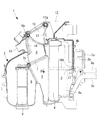
図1は、本発明の第1実施形態に係る車両用空調装置(HVACユニット)の縦断面図であり、図に向かって右側が車両前方、左側が車両後方(車内側)である。この車両用空調装置1は、自動車等の車両のダッシュボードに内蔵されるものであり、例えば樹脂成形されたユニットケース2を備えている。
Hereinafter, embodiments of the present invention will be described with reference to the drawings.
[First Embodiment]
FIG. 1 is a longitudinal sectional view of a vehicle air conditioner (HVAC unit) according to a first embodiment of the present invention, in which the right side is a vehicle front and the left side is a vehicle rear (vehicle inside). The
ユニットケース2内には、図示しないブロアユニットから送られてくる空気流を前後方向(図1の左右方向)の流れに変換し、下流側へと流通させる空気流路3が形成されている。空気流路3の上流部位には、図示省略の冷凍サイクルを構成する蒸発器4が略鉛直に配設されている。
In the
空気流路3は、蒸発器4の下流側においてバイパス流路5と加熱流路6とに分岐している。この分岐部には、エアミックスダンパ7が回転軸7a回りに回動可能に配設され、その回動位置によってバイパス流路5と加熱流路6とに流通される空気流の流量割合が調整可能とされている。加熱流路6には、エンジン冷却水回路8a,8bからの冷却水が循環されるヒーターコア8、あるいはこれに代わるPTCヒータ等の加熱部材が略鉛直に配設されている。
The
バイパス流路5および加熱流路6は、エアミックスダンパ7下流のエアミックス域9で合流し、その下流側に形成されているフェイス吹出流路10、フット吹出流路11およびデフ吹出流路12の3つの吹出流路に連通されている。フェイス吹出流路10とデフ吹出流路12との間には、デフ/フェイスダンパ(吹出モード切替えダンパ)13が回転軸13a回りに回動可能に配設されている。また、フット吹出流路11の入口には、フットダンパ(吹出モード切替えダンパ)14が回転軸14a回りに回動可能に配設されている。
The
デフ/フェイスダンパ13は、フェイス吹出流路10を全閉する位置と、デフ吹出流路12を全閉する位置との間で回動可能とされている。一方、フットダンパ14は、フット吹出流路11を全閉する位置と、フェイス吹出流路10およびデフ吹出流路12に連なる流路を全閉する位置との間で回動可能とされている。フットダンパ14およびデフ/フェイスダンパ13は、吹出モードに対応した位置にそれぞれ回動調整される。
The differential /
冷房運転時には、冷凍サイクルに含まれる図示しない冷媒コンプレッサによって圧縮され、さらに凝縮器(コンデンサ)で凝縮された液相状の高圧冷媒が、膨張弁ケース2a内に収容された図示しない膨張弁によって所定の圧力に減圧された後、高圧冷媒管路4aから蒸発器4に流れる。この冷媒は、蒸発器4で蒸発(気化)することにより蒸発器4の熱を奪ってこれを冷却した後、低圧冷媒管路4bから再び冷媒コンプレッサに還流する。
During the cooling operation, a liquid-phase high-pressure refrigerant compressed by a refrigerant compressor (not shown) included in the refrigeration cycle and further condensed by a condenser (condenser) is supplied to a predetermined pressure by an expansion valve (not shown) housed in the
図示しないブロアユニットから空気流路3に流れてくる空気流は、上記のように冷媒の気化熱で冷却された蒸発器4を通過して冷やされ、エアミックスダンパ7の回動位置に応じた分配率でバイパス流路5と加熱流路6に分配される。加熱流路6に流れた冷却空気はヒーターコア8で加温されてエアミックス域9でバイパス流路5を流れて来た冷却空気と合流した後、各吹出流路10,11,12から車室内に吹き出されて空調に供される。
The air flow flowing from the blower unit (not shown) into the
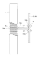
蒸発器4において冷媒が気化する際に発生する冷媒流動音(気化音)を抑制するべく、蒸発器4の面方向中央部付近をユニットケース2の構造体、例えば前面板2bに連結するブラケット16A(連結部材)が設けられている。図2にも示すように、このブラケット16Aは、例えば帯状の金属板を略U字状に折曲することにより、Uターン部16Aaと一対の締結片16Abとを備えるように形成されている。
In order to suppress the refrigerant flow noise (vaporization noise) generated when the refrigerant is vaporized in the
ブラケット16AのUターン部16Aaは、蒸発器4を構成する多数のチューブ4cのうち、蒸発器4の面方向中央部付近に位置する1本のチューブ4cに巻回されている。このUターン部16Aaとチューブ4cとの間は相対移動が起こらないようにする。例えば、Uターン部16Aaにチューブ4cを圧迫的に挟持させたり、Uターン部16Aaとチューブ4cとの間を接着、溶着する等して相対移動を防止する。また、ブラケット16Aの締結片16Abは、ユニットケース2の前面板2bに形成された締結ボス2cにビス17で締結されている。
The U-turn part 16Aa of the
ブラケット16Aの材質、形状や、ブラケット16Aと蒸発器4の面方向中央部付近との連結構造は上記の構造に限定されない。例えば、ブラケット16Aと同じ働きを持つ突起部をユニットケース2の前面板2bに一体成形してもよい。
The material and shape of the
以上のように構成された車両用空調装置1によれば、ユニットケース2の内部において蒸発器4の面方向中央部付近がブラケット16Aによってユニットケース2の前面板2bに連結され、固定される。これにより、蒸発器4は、その面方向に直交する方向(厚み方向)に振動することを規制される。したがって、蒸発器4から放射される冷媒流動音の音量が制限され、冷媒流動音が車両用空調装置1の吹出流路10,11,12から車内側に漏洩しにくくなり、ひいては車内の静粛性を高めることができる。
According to the
[第2実施形態]
図3は、本発明の第2実施形態を示す横断面図である。この図3は、第1実施形態において図2が示す位置と同位置の横断面図である。
[Second embodiment]
FIG. 3 is a cross-sectional view showing a second embodiment of the present invention. FIG. 3 is a cross-sectional view at the same position as that shown in FIG. 2 in the first embodiment.
この第3実施形態では、蒸発器4の面方向中央部付近をユニットケース2の前面板2bに連結する連結部材としてスプリング16Bが用いられている。このスプリング16Bは、そのコイル部の両端にフック16Ba,16Bbが形成された引っ張りスプリングである。
In the third embodiment, a
例えば、蒸発器4の面方向中央部付近に位置する、隣り合う2本のチューブ4cの間に、平面形状が略T字状をなす引っ張り部材20が後方(車内側)から差し込まれている。この引っ張り部材20は、樹脂または金属製であり、蒸発器4の複数のチューブ4cに当接する当接片20aと、この当接片20aの幅方向中間部から前方に延びて2本のチューブ4c間に差し込まれる差込片20bとを備えている。
For example, a
スプリング16Bの一方のフック16Baは引っ張り部材20の差込片20b後端の掛止孔に掛止され、他方のフック16Bbはユニットケース2の前面板2bに形成された掛止片2dの掛止孔に掛止されている。このように両端のフック16Ba,16Bbが掛止された時、スプリング16Bが所定の張力で引っ張られるように、予めスプリング16Bの長さや張力が設定される。
One hook 16Ba of the
このように、連結部材としてスプリング16B等の付勢部材を用い、蒸発器4の面方向中央部付近を引っ張るように付勢することにより、蒸発器4に任意の付勢力を付与することができる。このため、蒸発器4の振動を規制し、蒸発器4から放射される冷媒流動音をより有効に抑制することができる。
As described above, by using the urging member such as the spring 16 </ b> B as the connecting member and urging the
また、スプリング16Bを付勢力の異なるものに交換して蒸発器4の固有振動数を変更することができる。このため、車両用空調装置1の使用条件(例えば冷媒の種類および圧力、車両の種類等)に見合った設定をして冷媒流動音を効果的に抑制することができる。
In addition, the natural frequency of the
なお、連結部材としては、スプリング16Bに限らず、例えばゴム等の弾性材料からなるバンド等に置き換えてもよい。要するに、蒸発器4の面方向中央部付近とユニットケース2の前面板2bとの間に引っ張り力を作用させるものであればよい。あるいは逆に、蒸発器4の面方向中央部付近とユニットケース2の前面板2bとの間を拡張させるように押圧する部材を連結部材として用いてもよい。例えば、弾性材料からなるブロック等を弾装してもよい。
The connecting member is not limited to the
[第3実施形態]
図4は、本発明の第3実施形態を示す車両用空調装置1の縦断面図である。この第3実施形態において図1に示す第1実施形態と異なるのは、蒸発器4の面方向中央部付近をユニットケース2の構造体に連結する連結部材としてのブラケット16Cの付近のみであり、その他の部分の構成は同一である。したがって、同一構成を有する各部には同一符号を付して重複する説明は省略する。
[Third embodiment]
FIG. 4 is a longitudinal sectional view of a
蒸発器4の面方向中央部付近に設けられているブラケット16Cは、図5に示すように、第1実施形態のブラケット16A(図2参照)とほぼ同様な略U字状の平面形状を有しており、Uターン部16Caと一対の締結片16Cbとを備えている。Uターン部16Caは、蒸発器4を構成する多数のチューブ4cのうち、蒸発器4の面方向中央部付近に位置する1本のチューブ4cに巻回され、チューブ4cに対して相対移動しないようにされている。
As shown in FIG. 5, the
ブラケット16Cの一対の締結片16Cbが締結されるユニットケース2の構造体としては、蒸発器4の直近位置に設けられて空気流路3(5,6)を車両の運転席側と助手席側とに分割する独立空調隔壁2eが用いられている。この独立空調隔壁2eは第1実施形態を示す図1にも図示されているものである(符号はなし)。
As a structure of the
図5に示すように、独立空調隔壁2eは垂直な平板状であり、例えばユニットケース2の内面に一体に成形されている。この独立空調隔壁2eにおける蒸発器4側の縁部付近には、車幅方向左右に突出する一対の締結片2fが形成されている。そして、これら一対の締結片2fに、ブラケット16Cの一対の締結片16Cbがそれぞれ重ねられてビス22およびナット23によって締結される。
As shown in FIG. 5, the independent air-
以上の構成により、蒸発器4の面方向中央部付近と独立空調隔壁2eとの間がブラケット16Cにより連結される。これにより、蒸発器4の厚み方向への振動や共振がブラケット16Cによって規制され、蒸発器4からの冷媒流動音の放射が抑制される。
With the above configuration, the
このように、一端が蒸発器4に連結されるブラケット16Cの他端を、元来より蒸発器4の直近位置に設けられている独立空調隔壁2eに連結して蒸発器4の振動を規制する構造とすることにより、ブラケット16Cの長さを短くしてその剛性を高め、蒸発器4を効果的に防振して冷媒流動音の放射防止に貢献することができる。
In this manner, the other end of the
[第4実施形態]
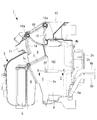
図6は、本発明の第4実施形態を示す車両用空調装置51の縦断面図である。この車両用空調装置51において、図1に示す第1実施形態の車両用空調装置1と異なるのは、蒸発器4の周囲を囲むように設けられている通風防止部材25の材質のみであり、その他の部分の構成は同一である。したがって、同一構成を有する各部には同一符号を付して重複する説明は省略する。
[Fourth embodiment]
FIG. 6 is a longitudinal sectional view of a
図1および図4では省略されているが、蒸発器4の周囲とユニットケース2の内面との間には通風防止部材25が介装されている。この通風防止部材25は、蒸発器4の上流側の空気が、ユニットケース2と蒸発器4との間をすり抜けてしまうことによる空調効率の低下を防止する気密部材である。一般に、この通風防止部材25の材質としては低密度なウレタンスポンジ等が用いられているが、本実施形態では、より高密度なブチルゴムやシリコンゴム等の制振材料が用いられている。このような制振材料を用いることにより、ユニットケース2の内部における蒸発器4の振動を抑制することができる。
Although not shown in FIGS. 1 and 4, a
上記構成の車両用空調装置51によれば、蒸発器4の周囲とユニットケース2の内面との間に設けられる通風防止部材25によって蒸発器4の振動が制振され、蒸発器4から放射される冷媒流動音の音量が制限される。
通風防止部材25は元来より蒸発器4とユニットケース2の内面との間に設けられている部材であり、その材質を変更するだけなので、コストアップを招くことなく蒸発器4の静粛性を向上させることができる。
According to the
The
以上説明したように、上記の各実施形態によれば、簡素で軽量、且つ安価な構成により、ユニットケース2内に設置された蒸発器4から放射される冷媒流動音の音量を制限し、車内の静粛性を高めることができる。
As described above, according to each of the above embodiments, the volume of the refrigerant flowing sound radiated from the
なお、本発明は上記実施形態の構成のみに限定されるものではなく、本発明の要旨を逸脱しない範囲内において適宜変更や改良を加えることができ、このように変更や改良を加えた実施形態も本発明の権利範囲に含まれるものとする。 Note that the present invention is not limited to only the configuration of the above-described embodiment, and appropriate changes and improvements can be made without departing from the spirit of the present invention. Is also included in the scope of the present invention.
例えば、ユニットケース2の内部構造(レイアウト等)や、蒸発器4およびヒーターコア8と各空気流路3,5,6,9等との相対位置関係、さらには各ダンパ7,13,14および各吹出流路10,11,12との相対位置関係等は、上記実施形態の態様に限定されることはなく、他の構造であっても構わない。
For example, the internal structure (layout and the like) of the
1 車両用空調装置
2 ユニットケース
2b 前面板(ユニットケースの構造体)
2e 独立空調隔壁(ユニットケースの構造体)
3 空気流路
4 蒸発器
4c チューブ
16A ブラケット(連結部材)
16B スプリング(連結部材)
16C ブラケット(連結部材)
20 引っ張り部材
25 通風防止部材
DESCRIPTION OF
2e Independent air conditioning partition (unit case structure)
3
16B Spring (connecting member)
16C bracket (connection member)
20
Claims (3)
前記ユニットケースの内部に形成された空気流路と、
前記空気流路内に配設された蒸発器と、
前記蒸発器の面方向中央部付近を前記ユニットケースの構造体に連結する連結部材と、
を備えた車両用空調装置。 A unit case built into the dashboard of the vehicle,
An air passage formed inside the unit case,
An evaporator disposed in the air flow path,
A connecting member for connecting the vicinity of the center in the surface direction of the evaporator to the structure of the unit case,
A vehicle air conditioner comprising:
Priority Applications (5)
| Application Number | Priority Date | Filing Date | Title |
|---|---|---|---|
| JP2016037680A JP6656949B2 (en) | 2016-02-29 | 2016-02-29 | Vehicle air conditioner |
| DE112017001032.2T DE112017001032T5 (en) | 2016-02-29 | 2017-02-21 | VEHICLE CLIMATE CONTROL DEVICE |
| CN201780006272.4A CN108698480A (en) | 2016-02-29 | 2017-02-21 | Air conditioner for vehicles |
| US16/067,856 US20190001785A1 (en) | 2016-02-29 | 2017-02-21 | Vehicle air conditioner |
| PCT/JP2017/006434 WO2017150285A1 (en) | 2016-02-29 | 2017-02-21 | Vehicle air conditioner |
Applications Claiming Priority (1)
| Application Number | Priority Date | Filing Date | Title |
|---|---|---|---|
| JP2016037680A JP6656949B2 (en) | 2016-02-29 | 2016-02-29 | Vehicle air conditioner |
Publications (3)
| Publication Number | Publication Date |
|---|---|
| JP2017154546A JP2017154546A (en) | 2017-09-07 |
| JP2017154546A5 JP2017154546A5 (en) | 2019-03-22 |
| JP6656949B2 true JP6656949B2 (en) | 2020-03-04 |
Family
ID=59742785
Family Applications (1)
| Application Number | Title | Priority Date | Filing Date |
|---|---|---|---|
| JP2016037680A Active JP6656949B2 (en) | 2016-02-29 | 2016-02-29 | Vehicle air conditioner |
Country Status (5)
| Country | Link |
|---|---|
| US (1) | US20190001785A1 (en) |
| JP (1) | JP6656949B2 (en) |
| CN (1) | CN108698480A (en) |
| DE (1) | DE112017001032T5 (en) |
| WO (1) | WO2017150285A1 (en) |
Family Cites Families (34)
| Publication number | Priority date | Publication date | Assignee | Title |
|---|---|---|---|---|
| GB1307365A (en) * | 1969-06-11 | 1973-02-21 | Leyland Gas Turbines Ltd | Rotary regenerative heat exchanger |
| GB1410781A (en) * | 1972-01-08 | 1975-10-22 | Penny R N | Rotary regenerative heat exchanger |
| FR2207267B1 (en) * | 1972-11-22 | 1976-01-30 | Bennes Marrel | |
| US4216937A (en) * | 1974-03-04 | 1980-08-12 | The Garrett Corporation | Heat exchanger mounting device |
| DE2604606A1 (en) * | 1976-02-06 | 1977-08-11 | Daimler Benz Ag | GAS TURBINE |
| US4286549A (en) * | 1979-12-03 | 1981-09-01 | Foster Wheeler Energy Corporation | Steam generator support system |
| FR2488953A1 (en) * | 1980-08-22 | 1982-02-26 | Renault | FAST FASTENING DEVICE FORMED OF A SPRING ASSEMBLY |
| FR2546287B1 (en) * | 1983-05-18 | 1988-02-05 | Sueddeutsche Kuehler Behr | HEAT EXCHANGER, PARTICULARLY FOR HEATING THE INTERIOR OF PASSENGER CARS |
| US4776387A (en) * | 1983-09-19 | 1988-10-11 | Gte Products Corporation | Heat recuperator with cross-flow ceramic core |
| JPH038014U (en) * | 1989-06-12 | 1991-01-25 | ||
| US5163505A (en) * | 1992-03-27 | 1992-11-17 | General Motors Corporation | Heater core retaining system |
| JPH08327285A (en) * | 1995-05-30 | 1996-12-13 | Sanden Corp | Multi-tube type heat exchanger |
| JP3692572B2 (en) * | 1995-10-12 | 2005-09-07 | 株式会社デンソー | Air conditioner |
| JP3136534B2 (en) * | 1996-07-12 | 2001-02-19 | 株式会社デンソー | Automotive air conditioners |
| JPH1178501A (en) * | 1997-09-04 | 1999-03-23 | Calsonic Corp | Cooling unit |
| JP3858466B2 (en) * | 1997-09-25 | 2006-12-13 | 株式会社デンソー | Automotive air conditioner |
| US6192698B1 (en) * | 1998-03-12 | 2001-02-27 | Denso Corporation | Vehicle-air-conditioning system with cooling degree estimator for left/right temperature control |
| US6474408B1 (en) * | 2000-08-31 | 2002-11-05 | Honeywell International Inc. | Heat exchanger with bypass seal allowing differential thermal expansion |
| DE10126467A1 (en) * | 2001-05-31 | 2003-01-02 | Norddeutsche Affinerie | Device for holding heating elements |
| US20050067139A1 (en) * | 2003-09-30 | 2005-03-31 | Valeo Climate Control Corp | Evaporator core seal |
| DE10359357A1 (en) * | 2003-12-16 | 2005-07-28 | Behr Gmbh & Co. Kg | Arrangement for fastening a heat exchanger, in particular a cooling module in a motor vehicle |
| JP2007210360A (en) * | 2006-02-07 | 2007-08-23 | Denso Corp | Air conditioner |
| JP2007283824A (en) * | 2006-04-13 | 2007-11-01 | Calsonic Kansei Corp | Seal structure of heat exchanger |
| JP4687544B2 (en) * | 2006-04-17 | 2011-05-25 | 日産自動車株式会社 | Piping fixing structure |
| DE102008002430C5 (en) * | 2007-07-11 | 2018-03-22 | Hanon Systems | Exhaust gas heat exchanger with vibration-damped exchanger tube bundle |
| JP4596046B2 (en) * | 2008-06-19 | 2010-12-08 | 株式会社デンソー | Air passage opening and closing device |
| US8997838B2 (en) * | 2009-07-10 | 2015-04-07 | Keihin Corporation | Vehicular air conditioning apparatus |
| JP5627297B2 (en) | 2010-05-31 | 2014-11-19 | 三菱重工業株式会社 | Air conditioner for vehicles |
| JP2012001124A (en) * | 2010-06-17 | 2012-01-05 | Japan Climate Systems Corp | Vehicular air conditioner |
| JP5090515B2 (en) * | 2010-11-29 | 2012-12-05 | 株式会社タクボ精機製作所 | Heat exchanger |
| US9150095B2 (en) * | 2012-09-14 | 2015-10-06 | Nissan Motor Co., Ltd. | Vibration suppression structure for front-end module |
| JP6048231B2 (en) * | 2013-03-11 | 2016-12-21 | マツダ株式会社 | Radiator support device for vehicle |
| JP6083339B2 (en) * | 2013-07-09 | 2017-02-22 | 株式会社デンソー | Air conditioner for vehicles |
| US10107567B2 (en) * | 2016-01-14 | 2018-10-23 | Denso International America, Inc. | Vehicle heat exchanger air guide |
-
2016
- 2016-02-29 JP JP2016037680A patent/JP6656949B2/en active Active
-
2017
- 2017-02-21 CN CN201780006272.4A patent/CN108698480A/en not_active Withdrawn
- 2017-02-21 WO PCT/JP2017/006434 patent/WO2017150285A1/en active Application Filing
- 2017-02-21 US US16/067,856 patent/US20190001785A1/en not_active Abandoned
- 2017-02-21 DE DE112017001032.2T patent/DE112017001032T5/en not_active Withdrawn
Also Published As
| Publication number | Publication date |
|---|---|
| WO2017150285A1 (en) | 2017-09-08 |
| US20190001785A1 (en) | 2019-01-03 |
| JP2017154546A (en) | 2017-09-07 |
| CN108698480A (en) | 2018-10-23 |
| DE112017001032T5 (en) | 2019-01-03 |
Similar Documents
| Publication | Publication Date | Title |
|---|---|---|
| EP1555150B1 (en) | Air-conditioning unit and vehicle air-conditioning apparatus | |
| US20160221414A1 (en) | Air conditioning unit | |
| WO2009145215A1 (en) | Air conditioner for vehicle | |
| JP6729606B2 (en) | Vehicle air conditioner | |
| JP6656949B2 (en) | Vehicle air conditioner | |
| JP5530748B2 (en) | Air conditioner for vehicles | |
| JP2001239819A (en) | Vehicular air conditioner | |
| JP2019156111A (en) | Air conditioner | |
| US11220153B2 (en) | Air conditioner for vehicle | |
| JP2005306166A (en) | Air-conditioner for vehicle | |
| JP3678211B2 (en) | Air conditioner for vehicles | |
| JP2003220820A (en) | Vehicular air conditioner | |
| WO2021079627A1 (en) | Vehicle air conditioner | |
| JP4013383B2 (en) | Air conditioner for vehicles | |
| JP2004231121A (en) | Vehicular air-conditioning unit and vehicular air-conditioning device | |
| JP6921731B2 (en) | Vehicle air conditioner | |
| JP2011207278A (en) | Air conditioning case | |
| JP3915259B2 (en) | Air conditioner for vehicles | |
| JP2005225249A (en) | Air-conditioner for vehicles | |
| JP4140458B2 (en) | Air conditioner for vehicles | |
| JP6790978B2 (en) | Blower | |
| JP2000225836A (en) | Air conditioner for vehicle | |
| JP2005199872A (en) | Air-conditioning unit, and air-conditioner for vehicle | |
| JP2005199871A (en) | Air-conditioning unit and air-conditioner for vehicle | |
| JP2012232662A (en) | Air conditioning unit and air conditioner for vehicle |
Legal Events
| Date | Code | Title | Description |
|---|---|---|---|
| A711 | Notification of change in applicant |
Free format text: JAPANESE INTERMEDIATE CODE: A712 Effective date: 20180613 |
|
| A521 | Request for written amendment filed |
Free format text: JAPANESE INTERMEDIATE CODE: A523 Effective date: 20190207 |
|
| A621 | Written request for application examination |
Free format text: JAPANESE INTERMEDIATE CODE: A621 Effective date: 20190207 |
|
| TRDD | Decision of grant or rejection written | ||
| A01 | Written decision to grant a patent or to grant a registration (utility model) |
Free format text: JAPANESE INTERMEDIATE CODE: A01 Effective date: 20200107 |
|
| A61 | First payment of annual fees (during grant procedure) |
Free format text: JAPANESE INTERMEDIATE CODE: A61 Effective date: 20200205 |
|
| R150 | Certificate of patent or registration of utility model |
Ref document number: 6656949 Country of ref document: JP Free format text: JAPANESE INTERMEDIATE CODE: R150 |