JP6653698B2 - Steerable medical device and pull wiring therein - Google Patents
Steerable medical device and pull wiring therein Download PDFInfo
- Publication number
- JP6653698B2 JP6653698B2 JP2017522079A JP2017522079A JP6653698B2 JP 6653698 B2 JP6653698 B2 JP 6653698B2 JP 2017522079 A JP2017522079 A JP 2017522079A JP 2017522079 A JP2017522079 A JP 2017522079A JP 6653698 B2 JP6653698 B2 JP 6653698B2
- Authority
- JP
- Japan
- Prior art keywords
- medical device
- pull wire
- pull
- peripheral surface
- steerable medical
- Prior art date
- Legal status (The legal status is an assumption and is not a legal conclusion. Google has not performed a legal analysis and makes no representation as to the accuracy of the status listed.)
- Active
Links
- 230000002093 peripheral effect Effects 0.000 claims description 33
- -1 Polyethylene Polymers 0.000 claims description 4
- 238000005452 bending Methods 0.000 claims description 4
- 238000007373 indentation Methods 0.000 claims description 4
- 239000000463 material Substances 0.000 claims description 4
- 239000013307 optical fiber Substances 0.000 claims description 4
- 239000004812 Fluorinated ethylene propylene Substances 0.000 claims description 3
- 239000004696 Poly ether ether ketone Substances 0.000 claims description 3
- 229920002614 Polyether block amide Polymers 0.000 claims description 3
- 239000004698 Polyethylene Substances 0.000 claims description 3
- 229920009441 perflouroethylene propylene Polymers 0.000 claims description 3
- 229920002530 polyetherether ketone Polymers 0.000 claims description 3
- 229920000573 polyethylene Polymers 0.000 claims description 3
- 239000004952 Polyamide Substances 0.000 claims description 2
- 229920001971 elastomer Polymers 0.000 claims description 2
- 239000000806 elastomer Substances 0.000 claims description 2
- HQQADJVZYDDRJT-UHFFFAOYSA-N ethene;prop-1-ene Chemical group C=C.CC=C HQQADJVZYDDRJT-UHFFFAOYSA-N 0.000 claims description 2
- 229920002647 polyamide Polymers 0.000 claims description 2
- 229920000728 polyester Polymers 0.000 claims description 2
- 229920002635 polyurethane Polymers 0.000 claims description 2
- 239000004814 polyurethane Substances 0.000 claims description 2
- 229920000915 polyvinyl chloride Polymers 0.000 claims description 2
- 239000004800 polyvinyl chloride Substances 0.000 claims description 2
- 229920001169 thermoplastic Polymers 0.000 claims description 2
- 229920001187 thermosetting polymer Polymers 0.000 claims description 2
- 239000004634 thermosetting polymer Substances 0.000 claims description 2
- 239000004416 thermosoftening plastic Substances 0.000 claims description 2
- 230000033001 locomotion Effects 0.000 description 4
- 230000001419 dependent effect Effects 0.000 description 3
- 239000004699 Ultra-high molecular weight polyethylene Substances 0.000 description 2
- 230000008901 benefit Effects 0.000 description 2
- 229920000785 ultra high molecular weight polyethylene Polymers 0.000 description 2
- 241000208140 Acer Species 0.000 description 1
- 238000004026 adhesive bonding Methods 0.000 description 1
- 230000009286 beneficial effect Effects 0.000 description 1
- 230000005540 biological transmission Effects 0.000 description 1
- 230000000903 blocking effect Effects 0.000 description 1
- 239000004020 conductor Substances 0.000 description 1
- 230000008878 coupling Effects 0.000 description 1
- 238000010168 coupling process Methods 0.000 description 1
- 238000005859 coupling reaction Methods 0.000 description 1
- 239000007788 liquid Substances 0.000 description 1
- 229920000642 polymer Polymers 0.000 description 1
- 239000002861 polymer material Substances 0.000 description 1
- 238000005476 soldering Methods 0.000 description 1
- 238000003466 welding Methods 0.000 description 1
Images


Classifications
-
- A—HUMAN NECESSITIES
- A61—MEDICAL OR VETERINARY SCIENCE; HYGIENE
- A61M—DEVICES FOR INTRODUCING MEDIA INTO, OR ONTO, THE BODY; DEVICES FOR TRANSDUCING BODY MEDIA OR FOR TAKING MEDIA FROM THE BODY; DEVICES FOR PRODUCING OR ENDING SLEEP OR STUPOR
- A61M25/00—Catheters; Hollow probes
- A61M25/01—Introducing, guiding, advancing, emplacing or holding catheters
- A61M25/0105—Steering means as part of the catheter or advancing means; Markers for positioning
- A61M25/0133—Tip steering devices
- A61M25/0147—Tip steering devices with movable mechanical means, e.g. pull wires
-
- A—HUMAN NECESSITIES
- A61—MEDICAL OR VETERINARY SCIENCE; HYGIENE
- A61M—DEVICES FOR INTRODUCING MEDIA INTO, OR ONTO, THE BODY; DEVICES FOR TRANSDUCING BODY MEDIA OR FOR TAKING MEDIA FROM THE BODY; DEVICES FOR PRODUCING OR ENDING SLEEP OR STUPOR
- A61M25/00—Catheters; Hollow probes
- A61M25/01—Introducing, guiding, advancing, emplacing or holding catheters
- A61M25/0105—Steering means as part of the catheter or advancing means; Markers for positioning
- A61M25/0133—Tip steering devices
- A61M25/0158—Tip steering devices with magnetic or electrical means, e.g. by using piezo materials, electroactive polymers, magnetic materials or by heating of shape memory materials
-
- A—HUMAN NECESSITIES
- A61—MEDICAL OR VETERINARY SCIENCE; HYGIENE
- A61M—DEVICES FOR INTRODUCING MEDIA INTO, OR ONTO, THE BODY; DEVICES FOR TRANSDUCING BODY MEDIA OR FOR TAKING MEDIA FROM THE BODY; DEVICES FOR PRODUCING OR ENDING SLEEP OR STUPOR
- A61M25/00—Catheters; Hollow probes
- A61M25/01—Introducing, guiding, advancing, emplacing or holding catheters
- A61M25/0105—Steering means as part of the catheter or advancing means; Markers for positioning
- A61M2025/0166—Sensors, electrodes or the like for guiding the catheter to a target zone, e.g. image guided or magnetically guided
-
- A—HUMAN NECESSITIES
- A61—MEDICAL OR VETERINARY SCIENCE; HYGIENE
- A61M—DEVICES FOR INTRODUCING MEDIA INTO, OR ONTO, THE BODY; DEVICES FOR TRANSDUCING BODY MEDIA OR FOR TAKING MEDIA FROM THE BODY; DEVICES FOR PRODUCING OR ENDING SLEEP OR STUPOR
- A61M25/00—Catheters; Hollow probes
- A61M25/01—Introducing, guiding, advancing, emplacing or holding catheters
- A61M25/09—Guide wires
- A61M2025/09116—Design of handles or shafts or gripping surfaces thereof for manipulating guide wires
-
- A—HUMAN NECESSITIES
- A61—MEDICAL OR VETERINARY SCIENCE; HYGIENE
- A61M—DEVICES FOR INTRODUCING MEDIA INTO, OR ONTO, THE BODY; DEVICES FOR TRANSDUCING BODY MEDIA OR FOR TAKING MEDIA FROM THE BODY; DEVICES FOR PRODUCING OR ENDING SLEEP OR STUPOR
- A61M2205/00—General characteristics of the apparatus
- A61M2205/02—General characteristics of the apparatus characterised by a particular materials
-
- A—HUMAN NECESSITIES
- A61—MEDICAL OR VETERINARY SCIENCE; HYGIENE
- A61M—DEVICES FOR INTRODUCING MEDIA INTO, OR ONTO, THE BODY; DEVICES FOR TRANSDUCING BODY MEDIA OR FOR TAKING MEDIA FROM THE BODY; DEVICES FOR PRODUCING OR ENDING SLEEP OR STUPOR
- A61M25/00—Catheters; Hollow probes
- A61M25/01—Introducing, guiding, advancing, emplacing or holding catheters
- A61M25/09—Guide wires
Description
本発明は、操縦可能(steerable)医療装置、特にカテーテル又はシース(sheath)に関する。本発明は、更に、前述のタイプの操縦可能医療装置におけるプルワイヤリング(pull wire ring)の使用に関する。 The present invention relates to steerable medical devices, particularly catheters or sheaths. The invention further relates to the use of a pull wire ring in a steerable medical device of the type described above.
1以上のプルワイヤを使用することによりカテーテル又はシースのような操縦可能医療装置の遠位端部分に曲げ動作を与えることは、当技術分野において一般に知られている。プルワイヤは、医療装置に固定されている、時々制御リングとも称される、プルワイヤリングを用いて操縦可能装置の遠位端部分に取り付けられる。 It is generally known in the art to provide a bending motion to the distal end portion of a steerable medical device, such as a catheter or sheath, by using one or more pull wires. The pull wire is attached to the distal end portion of the steerable device using a pull wire ring, sometimes referred to as a control ring, that is secured to the medical device.
WO2014/064694A2、US8273073B2、US2014/0148673A1、US2014/0194814A1、US2005/0288656A1は、カテーテルのような操縦可能医療装置における従来のプルワイヤリングの使用を開示し、例示的に記載している。当技術分野において既知であるプルワイヤリングは、しばしば、中心メインルーメンを有する。メインルーメンは、カテーテルのメインルーメンの隙間(clearance)に本質的に適合され、器具又は診断ツールを収容する又は液体を輸送するような様々な目的で使用されることができる隙間を持つ。このメインルーメンは、特定の応用において、電気ケーブル、データケーブル又は光ファイバのような追加の導体線を受け入れるために利用可能ではない。装置壁内にこれらの補助的要素を導入する場合、補助的要素は、遠位端領域におけるプルワイヤリングにおいて終了する。 WO 2014 / 064694A2, US82737033B2, US2014 / 0148873A1, US2014 / 0194814A1, US2005 / 0288656A1 disclose and exemplify the use of conventional pull wiring in steerable medical devices such as catheters. Pull wiring known in the art often has a central main lumen. The main lumen is essentially adapted to the clearance of the main lumen of the catheter and has a gap that can be used for various purposes, such as to house instruments or diagnostic tools or to transport liquids. This main lumen is not available in certain applications to accept additional conductor wires, such as electrical cables, data cables or optical fibers. When introducing these auxiliary elements into the device wall, the auxiliary elements terminate in pull wiring in the distal end region.
US2012/0078076A1は、遠位端部分においてプルワイヤリングを持つ操縦可能医療装置を開示している。リングは、プルワイヤが終了する偏心リセス(eccentric recess)を有する。複数のワイヤが、装置の中心ルーメンを通過する。 US 2012/0078076 A1 discloses a steerable medical device with a pull wiring at the distal end portion. The ring has an eccentric recess where the pull wire terminates. Multiple wires pass through the central lumen of the device.
従来技術において発見された中心的な不利点は、これらの補助的要素が、遠位端を直接的に進行させるプルワイヤリングを越えてリードされることができないことであり、これは、全体として操縦可能医療装置の機能性及び有効性を制限する。 A central disadvantage discovered in the prior art is that these ancillary elements cannot be led over a pull wiring that directly advances the distal end, which in turn leads to maneuvering. Limit the functionality and effectiveness of possible medical devices.
本発明の目的は、改良された機能性を持つ操縦可能医療装置、特にカテーテル、シース又はガイドワイヤを提供することである。 It is an object of the present invention to provide a steerable medical device with improved functionality, in particular a catheter, sheath or guidewire.
本発明の他の目的は、改良された機能性を持つカテーテル、シース又はガイドワイヤのような操縦可能医療装置におけるプルワイヤリングの使用を提供することである。 It is another object of the present invention to provide for the use of pull wiring in a steerable medical device such as a catheter, sheath or guidewire with improved functionality.
本発明の第1の態様において、操縦可能医療装置、特にカテーテル、シース又はガイドワイヤが、提示され、前記装置は、メインルーメンを規定する装置本体と、前記装置の近位端部分から前記装置の遠位端部分に向けて延在する少なくとも1つのプルワイヤと、前記装置の前記遠位端部分内に配置されたプルワイヤリングとを有し、前記プルワイヤは、前記プルワイヤリングに取り付けられ、前記装置に曲げ動作を与えるように構成され、前記操縦可能医療装置において使用される前記プルワイヤリングは、第1の端面及び前記第1の端面の反対側の第2の端面、前記第1及び第2の端面の間にそれぞれ延在する外周面及び内周面、少なくとも1つのプルワイヤ、好ましくは2以上のプルワイヤを前記リングに取り付ける固定手段を有し、更に、前記第1の端面から前記第2の端面まで延在する少なくとも1つの偏心リセスを有し、前記リセスは、少なくとも1つの補助的要素に対する通路を規定する。 In a first aspect of the present invention, a steerable medical device, particularly a catheter, sheath or guidewire, is presented wherein the device comprises a device body defining a main lumen, and a proximal end portion of the device. At least one pull wire extending toward a distal end portion, and a pull wiring disposed within the distal end portion of the device, wherein the pull wire is attached to the pull wiring and the device includes The pull wiring configured to provide a bending motion and used in the steerable medical device includes a first end face and a second end face opposite the first end face, the first and second end faces. Fixing means for attaching at least one pull wire, preferably two or more pull wires, to said ring, each of which has an outer peripheral surface and an inner peripheral surface extending therebetween. To have at least one eccentric recess extending from said first end surface to said second end surface, the recess defines a passage for at least one auxiliary element.
前記操縦可能装置は、前記プルワイヤリングの前記偏心リセスを通って、前記プルワイヤリングから前記装置の遠位端に向けて延在する少なくとも1つの補助的要素を有する。 The steerable device has at least one auxiliary element extending from the pull wiring toward the distal end of the device through the eccentric recess of the pull wiring.
本発明の中心的利益は、前記リングに設けられた前記偏心リセスが、前記装置のメインルーメンを塞ぐことなく前記プルワイヤリングをも超えて前記操縦可能医療装置の遠位端に向けて補助的要素の導入を可能にすることである。ガイドワイヤと同様に、新規のプルワイヤリングを用いて、補助的配線が、前記操縦可能医療装置の壁内に導入され、前記プルワイヤリングを超えて前記偏心リセスを通ってリードされることができることがわかった。したがって、とりわけ電力供給又は例えばデータケーブル、又は光ファイバを介するデータ伝送を要求しうる、追加の技術的機能を提供することにより、特に前記遠位端、先端における前記操縦可能医療装置の機能性を改良することが可能になる。 A central benefit of the present invention is that the eccentric recess provided in the ring allows the auxiliary element to extend beyond the pull wiring and into the distal end of the steerable medical device without blocking the main lumen of the device. Is to enable the introduction of Similar to a guidewire, using a novel pull wiring, ancillary wiring can be introduced into the wall of the steerable medical device and lead over the pull wiring and through the eccentric recess. all right. Thus, the functionality of the steerable medical device, especially at the distal end, the tip, is provided by providing additional technical functions, which may require, inter alia, a power supply or data transmission, for example via a data cable or optical fiber. It can be improved.
好ましくは、前記偏心リセスは、前記リングの外周面におけるへこみ(indentation)である。このようにして、前記リセスは、これ自体と、前記プルワイヤリングが導入されるスポットにおける前記操縦可能医療装置空洞壁との間に追加のルーメンを規定する。 Preferably, said eccentric recess is an indentation in the outer peripheral surface of said ring. In this way, the recess defines an additional lumen between itself and the steerable medical device cavity wall at the spot where the pull wiring is introduced.
好適な代替例において、前記偏心リセスは、前記リングの内周面におけるへこみである。この実施例において、前記リセスは、前記へこみ自体の中に規定された追加のルーメンにより前記内周面により規定された内部ルーメンを改良する。 In a preferred alternative, the eccentric recess is a depression in the inner peripheral surface of the ring. In this embodiment, the recess improves the internal lumen defined by the inner peripheral surface with an additional lumen defined within the indentation itself.
他の好適な代替例において、前記プルワイヤリングは、貫通孔として形成されたリセスを持つ。前記貫通孔は、例えば、円筒形断面を持ってもよく、又は前記操縦可能医療装置の壁の内側の特定の角度部分を覆う細長いリセスであってもよい。 In another preferred alternative, the pull wiring has a recess formed as a through hole. The through-hole may, for example, have a cylindrical cross-section, or may be an elongated recess covering a particular angular portion inside the wall of the steerable medical device.
他の好適な実施例において、前記リセスは、前記外周面から前記内周面まで延在するギャップである。換言すると、前記ギャップは、動径方向における、そうでなければ閉じていたリング構造を開く。前記ギャップは、例えば10°より小さい前記リングの小さな角度部分のみを覆う小さなスロットであることができる。代わりに、前記ギャップは、しかしながら、これより大きくてもよい。1つのギャップを持つ前記プルワイヤリングの断面形状は、馬蹄形に似ている。馬蹄形幾何形状は、より多数の追加の補助的要素が前記プルワイヤリングを越えて前記操縦可能医療装置の遠位端に向けてリードされるべきである場合に特に有用である。 In another preferred embodiment, the recess is a gap extending from the outer peripheral surface to the inner peripheral surface. In other words, the gap opens the otherwise closed ring structure in the radial direction. The gap may be a small slot that covers only a small angular portion of the ring, for example, less than 10 °. Alternatively, the gap may, however, be larger. The cross-sectional shape of the pull wiring with one gap resembles a horseshoe shape. The horseshoe geometry is particularly useful when a larger number of additional auxiliary elements are to be led beyond the pull wiring towards the distal end of the steerable medical device.
以上に、前記プルワイヤリングは、唯一の偏心リセスのみを参照して主に記載されている。しかしながら、前記リングが、複数の偏心リセスを有することも好適であり、1つの、いくつかの又は全ての偏心リセスは、前記リングの外周面におけるへこみ、前記リングの内周面におけるへこみ、貫通孔、若しくは外周面から内周面まで延在するギャップ、又はこれらの組み合わせからなるグループから選択される。 Above, the pull wiring has been described mainly with reference to only one eccentric recess. However, it is also preferred that the ring has a plurality of eccentric recesses, one, some or all of the eccentric recesses being recesses in the outer circumference of the ring, recesses in the inner circumference of the ring, through holes. Or a gap extending from the outer peripheral surface to the inner peripheral surface, or a combination thereof.
好ましくは、前記プルワイヤリングは、前記リングに取り付けられた支持構造を有する。前記支持構造は、前記操縦可能医療装置の動作中に与えられる力に耐えるために前記プルワイヤリングに対する追加の剛性を提供する。前記リングが、外周面から内周面まで延在する1以上のギャップを有する実施例において、前記支持構造で前記リングの構造を強化することは、特に有益である。好ましくは、前記支持構造は、少なくとも部分的に前記リングを埋め込む。 Preferably, the pull wiring has a support structure attached to the ring. The support structure provides additional stiffness to the pull wiring to withstand the forces applied during operation of the steerable medical device. In embodiments where the ring has one or more gaps extending from an outer peripheral surface to an inner peripheral surface, it is particularly beneficial to reinforce the structure of the ring with the support structure. Preferably, said support structure at least partially embeds said ring.
支持構造が提供される場合、好ましくは、前記少なくとも1つの偏心リセスが、前記支持構造を通って延在する。 If a support structure is provided, preferably the at least one eccentric recess extends through the support structure.
前記支持構造は、好ましくは、50D以上のショア硬度(Shore durometer)を持つ高分子材料からなる。前記ショア硬度は、例えば、標準化された分析において決定される。ショア硬度分析を記載する既知の規格は、DIN EN ISO 868、DIN ISO 7619-1又はASTM D2240を含む。 The support structure is preferably made of a polymer material having a Shore durometer of 50D or more. The Shore hardness is determined, for example, in a standardized analysis. Known standards describing Shore hardness analysis include DIN EN ISO 868, DIN ISO 7619-1 or ASTM D2240.
前記支持構造は、好ましくは、エラストマからなる。この高分子は、好適な実施例において、熱可塑性物質でありうる。特に、この材料が、ポリウレタン、ポリエチレン、ポリ塩化ビニル、ポリエーテルブロックアミド(Pebax)、ポリエーテルエーテルケトン(PEEK)、ポリアミド、熱硬化性ポリマ、シュリンクチューブ、特にフッ素化エチレンプロピレン(FEP)、ポリエステル、又はこれらの組み合わせからなるリストから選択されることが好ましい。 The support structure preferably comprises an elastomer. The polymer may be a thermoplastic in a preferred embodiment. In particular, this material can be polyurethane, polyethylene, polyvinyl chloride, polyether block amide (Pebax), polyetheretherketone (PEEK), polyamide, thermosetting polymer, shrink tube, especially fluorinated ethylene propylene (FEP), polyester , Or a combination thereof.
前記偏心リセスを通ってリードされることができる前記補助的要素は、好ましくは、電線、データケーブル、光ファイバ、又はこれらの組み合わせからなるリストから選択される。 The auxiliary element that can be led through the eccentric recess is preferably selected from a list consisting of wires, data cables, optical fibers, or combinations thereof.
第2の態様において、操縦可能医療装置の遠位端部分に対して曲げ動作を与えるためのプルワイヤリングの使用が提示され、少なくとも1つの補助的要素が、前記プルワイヤリングを越えて前記装置の前記遠位端に向けて通され、前記プルワイヤリングが、上に記載された好適な実施例のいずれかによって形成される。 In a second aspect, there is provided the use of a pull wiring to impart a bending motion to a distal end portion of the steerable medical device, wherein at least one auxiliary element extends over the pull wiring and the Passed toward the distal end, the pull wiring is formed by any of the preferred embodiments described above.
第3の態様において、本発明は、操縦可能医療装置、特にカテーテル、シース又はガイドワイヤにおいて使用するプルワイヤリングに関する。 In a third aspect, the invention relates to a steerable medical device, particularly a pull wiring for use in a catheter, sheath or guidewire.
第3の態様による本発明の目的は、操縦可能医療装置の機能性を改良する、前記操縦可能医療装置、特にカテーテル、シース又はガイドワイヤにおいて使用するプルワイヤリングを提供することである。 It is an object of the present invention according to a third aspect to provide a pull-wiring for use in a steerable medical device, in particular a catheter, sheath or guide wire, which improves the functionality of the steerable medical device.
この第3の態様において、操縦可能医療装置、特にカテーテル、シース又はガイドワイヤにおいて使用するプルワイヤリングが提示され、前記リングは、上に記載された実施例のいずれかによって形成される。特に、前記プルワイヤリングは、第1の端面及び前記第1の端面の反対側の第2の端面、前記第1及び第2の端面の間にそれぞれ延在する外周面及び内周面、並びに少なくとも1つ、好ましくは2以上のプルワイヤを前記リングに取り付ける固定手段を有し、前記リングは、更に、前記第1の端面から前記第2の端面まで延在する少なくとも1つの偏心リセスを有し、前記リセスは、少なくとも1つの補助的要素に対する通路を規定する。逆の状況下で、本発明に関して、前記リングの2つの端面の一方が、一般に、導入される場合に、前記医療装置の近位端に向けられ、他方の端面が、一般に、導入される場合に、前記医療装置の遠位端に向けられると理解される。 In this third aspect, there is provided a pull wiring ring for use in a steerable medical device, particularly a catheter, sheath or guide wire, said ring being formed by any of the embodiments described above. In particular, the pull wiring includes a first end surface, a second end surface opposite the first end surface, an outer peripheral surface and an inner peripheral surface extending between the first and second end surfaces, respectively, and at least Securing means for attaching one, preferably two or more pull wires to said ring, said ring further comprising at least one eccentric recess extending from said first end face to said second end face; The recess defines a passage for at least one auxiliary element. Under the opposite situation, with regard to the present invention, if one of the two end faces of the ring is generally directed to the proximal end of the medical device when introduced and the other end face is generally introduced Is understood to be directed to the distal end of the medical device.
本発明による操縦可能医療装置、特に請求項1に記載の装置、本発明による使用、特に請求項13に記載の使用、及び前記プルワイヤリングは、特に従属請求項に規定される同様の及び/又は同一の好適な実施例を持つ。 The steerable medical device according to the invention, in particular the device according to claim 1, the use according to the invention, in particular the use according to claim 13, and the pull-wiring may be similar and / or particularly as defined in the dependent claims. It has the same preferred embodiment.
更に、本発明の好適な実施例が、それぞれの独立請求項と従属請求項のいかなる組み合わせであることもできると理解される。 It is further understood that preferred embodiments of the invention can be any combination of the respective independent and dependent claims.
本発明のこれら及び他の態様は、以下に記載される実施例を参照して説明され、明らかである。 These and other aspects of the invention are apparent from and will be elucidated with reference to the embodiments described hereinafter.
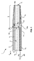
図1は、操縦可能医療装置1を描く。装置1は、外壁3と、外壁3により囲まれる内壁5を有する。装置1は、装置本体2、メインルーメン6及び偏心配置された補助的ルーメン7a、7bを有する。
FIG. 1 depicts a steerable medical device 1. The device 1 has an outer wall 3 and an inner wall 5 surrounded by the outer wall 3. The device 1 has a device body 2, a main lumen 6, and eccentrically arranged
装置1は、近位部分4、及び先端11により終了される遠位端部分9を有する。遠位端部分9において、第1の実施例によるプルワイヤリング100aが導入される。代わりに、他の好適な実施例のプルワイヤリング100b−eのいずれかが、同様に導入されることができる。プルワイヤリング100aは、遠位端部分9から離れるように向く第1の端面101と、装置1の遠位端又は先端11に向く第2の端面103とを有する。プルワイヤリング100aは、更に、装置1の外壁3で終端になる外周面109を有する。更に、プルワイヤリング100aは、好ましくはメインルーメン6の隙間以上の隙間を持つ内周面111を有する。図1の構成において、プルワイヤリング100aは、軸A1に対して実質的に同軸方向に向けられる。
The device 1 has a proximal portion 4 and a
リセス105aは、プルワイヤリング100aの外周面109内に形成される。リセス105aは、リング100aと装置1の壁との間の通路を規定し、前記通路は、補助的ルーメン7aから補助的ルーメン7bまで補助的要素200の移動を可能にする。
The
補助的ルーメン7bは、遠位端又は先端11まで全体的に延在するものとして図1に描かれているが、本発明の範囲内で、どこで追加の機能性が正確に提供されるべきかに依存して、プルワイヤリング100aと先端11との間のどこでも終了することができる。
Although the
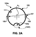
図1に示されるプルワイヤリング100aは、図2Aの概略的な断面図にも描かれる。図1にも示されたフィーチャに加えて、プルワイヤリング100aは、リング100aにプルワイヤを取り付ける固定手段107を更に有する。固定手段107は、前記プルワイヤとプルワイヤリング100aとの間のインタロッキング(interlocking)関係を可能にする機械的な結合手段を有しうる。代わりに又は加えて、固定手段107は、溶接、はんだ付け、結び付け又は接着を手段とするように、プルワイヤリング100aにプルワイヤ108を永久的に取り付けることを可能にする材料部分を有してもよい。
The
図2Aに示されるように、リセス105aは、外周面109から内側へのへこみとして形成される。代わりに、リセス105fは、図2Aの交差線により示されるように、内周面111から外側にへこみとして形成されることもできる。
As shown in FIG. 2A, the
図2B乃至D及び3の保証する記載において、同一の参照符号は、同一の要素に対して使用される。これらの要素に関して、以上の図1及び2Aの記載が参照される。 In the guaranteed description of FIGS. 2B-D and 3, the same reference numbers are used for the same elements. For these elements, reference is made to the description of FIGS. 1 and 2A above.
図2Bは、プルワイヤリングの変形例100bを描く。プルワイヤリング100bは、図1の医療装置1において代わりに使用されることができる。へこみの代わりに、プルワイヤリング100bは、貫通孔105bの形でリセスを有する。図2Bの実施例における貫通孔105bは、円形断面を持つ。しかしながら、異なる断面幾何形状も、例えば図3を参照して示されるように、本発明の範囲内である(以下を参照)。
FIG. 2B depicts a
プルワイヤリング100a及び100bの実施例が、閉じた円周面を持つリング幾何形状を示すが、図2Cは、他の変形例として開いた円周幾何形状を持つプルワイヤリング100cを示す。へこみ又は貫通孔の代わりに、プルワイヤリング100cは、ギャップ104cを有する。ギャップ104cは、外周面109から内周面111まで延在し、角度αにわたって開口を作成する。角度αが大きいほど、2つのギャップの端部の間に規定される通路は大きくなる。図2Cのプルワイヤリング100cは、したがって、支持構造110に完全に埋め込まれない場合に馬蹄形幾何形状を持つ。好ましくは、図2Cに示されるように、プルワイヤリング100cは、支持構造110を有する。貫通孔105cの形の偏心リセスは、好ましくは、支持構造110内に形成され、支持構造110を通って延在する。支持構造を持たない実施例において、ギャップ104cは、少なくとも1つの補助的要素に対する通路を規定する前記偏心リセスを構成する。
While the embodiment of the
他の実施例において、図2Dは、セグメント化されたプルワイヤリング100dを示す。セグメント化されたプルワイヤリング100dは、1つではなく、2つのギャップ104dを有し、2つのギャップ104dは、それぞれ、外周面109から内周面111まで延在する。前記ギャップは、それぞれ、角度β及びγに広がる。描かれた実施例において、βはγに等しい。プルワイヤリング100dのセグメントは、図1の装置1の内壁に互いから独立して固定されるか、又は、好ましくは図2Dに示されるように、増大された安定性のために支持構造110内に埋め込まれるかのいずれかである。ギャップ104dの内側で、貫通孔105dの形の2つの偏心リセスは、支持構造110内に形成され、支持構造110を通って延在する。
In another embodiment, FIG. 2D shows a
図3は、本発明によるプルワイヤリングの他の実施例100eを示す。プルワイヤリング100eは、ベースボディ117の周りに延在する支持構造110eとともに示される。支持構造110eは、焼嵌め(shrink-fit)チューブ又は上に記載された好適な実施例の1つによる従来の高分子材料であってもよく、外周面109を規定する。
FIG. 3 shows another embodiment 100e of the pull wiring according to the present invention. The pull wiring 100e is shown with a
プルワイヤリング100eは、複数の偏心リセス105eを有する。偏心リセス105eは、ベースボディ117の内側に形成される。
The pull wiring 100e has a plurality of
プルワイヤリング100eが、周りに支持構造110eを持たない実施例において使用される場合、リセス105eは、それぞれ開口115を持つへこみと見なされるべきである。そうでなければ、リセス105eは、本発明に関して貫通孔と見なされるべきである。
If the pull wiring 100e is used in embodiments that do not have a
プルワイヤリング100eは、更に、複数のリブ119を有する。リブ119は、プルワイヤ108を保持するように構成される。好ましくは、プルワイヤ108は、図3に示されるようにリブ119の周りで曲げられる。図3に示された実施例は、例えばポリエチレン又は超高分子量ポリエチレン(UHMW−PE)からなる、重合体プルワイヤとともに使用するのに特に適している。特に、この実施例は、ダイニーマプルワイヤとともに使用するのに適している。
The pull wiring 100e further has a plurality of
プルワイヤ108は、プルワイヤリング100eが支持構造110eなしで又はベースボディ117上に支持構造110eを取り付ける前に使用される場合、開口115を通ってプルワイヤリング100e内に挿入されうる。
The
本発明の上記記載において、操縦可能医療装置が概して記載されている。本発明の好適な実施例によると、特に、操縦可能カテーテル又はシースは、操縦可能医療装置の特定の例として使用されうる。 In the above description of the invention, a steerable medical device is generally described. According to a preferred embodiment of the present invention, in particular, a steerable catheter or sheath may be used as a particular example of a steerable medical device.
開示された実施例に対する他の変形例は、図面、開示及び添付の請求項の検討から、請求された発明を実施する当業者により理解及び達成されることができる。 Other variations to the disclosed embodiments can be understood and effected by those skilled in the art in practicing the claimed invention, from a study of the drawings, the disclosure, and the appended claims.
請求項において、単語「有する」は、他の要素を除外せず、不定冠詞「1つの」は、複数を除外しない。 In the claims, the word "comprising" does not exclude other elements, and the indefinite article "one" does not exclude a plurality.
単一のユニットは、請求項に記載された複数のアイテムの機能を満たしてもよい。特定の方策が相互に異なる従属請求項に記載されるという単なる事実は、これらの方策の組み合わせが有利に使用されることができないことを示さない。 A single unit may fulfill the functions of several items recited in the claims. The mere fact that certain measures are recited in mutually different dependent claims does not indicate that a combination of these measures cannot be used to advantage.
請求項内の参照符号は、範囲を限定すると解釈されるべきではない。 The reference signs in the claims shall not be construed as limiting the scope.
この文書において、単語「及び/又は」が使用される場合、要素の1つ、又はいくつか又は全てが選択されるべきであると理解される。 In this document, where the word "and / or" is used, it is understood that one, some or all of the elements should be selected.
Claims (7)
メインルーメンを規定する装置本体と、
前記装置の近位端部分から前記装置の遠位端部分に延在する少なくとも1つのプルワイヤと、
前記装置の前記遠位端部分に配置されたプルワイヤリングであって、前記プルワイヤが、前記プルワイヤリングに取り付けられ、前記装置の曲げ動作を与えるように構成される、当該プルワイヤリングと、
を有し、前記プルワイヤリングが、
第1の端面及び前記第1の端面の反対側の第2の端面と、
前記第1及び第2の端面の間にそれぞれ延在する外周面及び内周面と、
前記プルワイヤリングに少なくとも1つのプルワイヤを取り付ける固定手段と、
を有し、
前記プルワイヤリングが、前記第1の端面から前記第2の端面まで延在する少なくとも1つの偏心リセスを有し、前記偏心リセスが、電線、データケーブル、及び光ファイバのグループから選択された少なくとも1つの補助的要素に対する通路を規定し、前記操縦可能医療装置が、前記プルワイヤリングの前記偏心リセスを通って前記装置の遠位端に向かって延在する少なくとも1つの補助的要素を有し、前記偏心リセスが、前記外周面におけるへこみ、前記内周面におけるへこみ、又は前記外周面から前記内周面まで延在するギャップである、
操縦可能医療装置。 In a steerable medical device,
An apparatus body defining a main lumen;
At least one pull wire extending from a proximal end portion of the device to a distal end portion of the device;
A pull wiring disposed on the distal end portion of the device, wherein the pull wire is attached to the pull wiring and configured to provide a bending action of the device;
Having the pull wiring,
A first end face and a second end face opposite to the first end face;
An outer peripheral surface and an inner peripheral surface extending between the first and second end surfaces, respectively;
A fixing means for attaching at least one pull wire to the pull wire ring,
Has,
The pull wire ring has at least one eccentric recess extending from said first end surface to said second end surface, the eccentric recess, wires, data cables, and at least one selected from a group of optical fibers one of the defining a passage for the auxiliary elements, the steerable medical device, have at least one auxiliary element extending toward the distal end of the pull wire ring of the said through an eccentric recess apparatus, wherein The eccentric recess is a dent on the outer peripheral surface, a dent on the inner peripheral surface, or a gap extending from the outer peripheral surface to the inner peripheral surface,
Steerable medical device.
1つの、一部の又は全ての偏心リセスが、
前記プルワイヤリングの前記外周面におけるへこみ、
前記プルワイヤリングの前記内周面におけるへこみ、
貫通孔、
前記外周面から前記内周面まで延在するギャップ、
からなるグループから選択される、
請求項1に記載の操縦可能医療装置。 The pull wire ring has a plurality of eccentric recesses,
One, some or all eccentric recesses
Dent in the outer peripheral surface of the pull wire ring,
Indentations in the inner peripheral surface of the pull wire ring,
Through hole,
A gap extending from the outer peripheral surface to the inner peripheral surface,
Selected from the group consisting of
The steerable medical device according to claim 1.
エラストマ、
熱可塑性物質、
ポリウレタン、
ポリエチレン
ポリ塩化ビニル、
ポリエーテルブロックアミド、
ポリエーテルエーテルケトン、
ポリアミド、
熱硬化性ポリマ、
シュリンクチューブ、
フッ素化エチレンプロピレン、
ポリエステル、
又はこれらの組み合わせ、
の少なくとも1つからなる、
請求項3に記載の操縦可能医療装置。 Said support structure of said pull wire ring,
Elastomer,
Thermoplastics,
Polyurethane,
Polyethylene polyvinyl chloride,
Polyether block amide,
Polyetheretherketone,
polyamide,
Thermosetting polymer,
Shrink tube,
Fluorinated ethylene propylene,
polyester,
Or a combination of these,
Consisting of at least one of
A steerable medical device according to claim 3 .
Applications Claiming Priority (3)
| Application Number | Priority Date | Filing Date | Title |
|---|---|---|---|
| EP14191734 | 2014-11-04 | ||
| EP14191734.4 | 2014-11-04 | ||
| PCT/EP2015/075660 WO2016071378A1 (en) | 2014-11-04 | 2015-11-04 | Steerable medical device, and use of a pull wire ring therein |
Publications (3)
| Publication Number | Publication Date |
|---|---|
| JP2017536158A JP2017536158A (en) | 2017-12-07 |
| JP2017536158A5 JP2017536158A5 (en) | 2018-12-06 |
| JP6653698B2 true JP6653698B2 (en) | 2020-02-26 |
Family
ID=51893856
Family Applications (1)
| Application Number | Title | Priority Date | Filing Date |
|---|---|---|---|
| JP2017522079A Active JP6653698B2 (en) | 2014-11-04 | 2015-11-04 | Steerable medical device and pull wiring therein |
Country Status (5)
| Country | Link |
|---|---|
| US (1) | US10821265B2 (en) |
| EP (1) | EP3215210B1 (en) |
| JP (1) | JP6653698B2 (en) |
| CN (1) | CN107148291B (en) |
| WO (1) | WO2016071378A1 (en) |
Families Citing this family (4)
| Publication number | Priority date | Publication date | Assignee | Title |
|---|---|---|---|---|
| EP3518779B1 (en) * | 2016-09-29 | 2021-06-16 | Koninklijke Philips N.V. | Pullwire crown and crown sleeve for catheter assembly |
| WO2022272006A1 (en) * | 2021-06-25 | 2022-12-29 | Wanliang Shan | Steerable robotic needles with tunable stiffness segments for large curvature maneuvers |
| CN113491816B (en) * | 2021-07-06 | 2023-06-27 | 上海康德莱医疗器械股份有限公司 | Electric positioning controllable bending guide wire |
| CN117442846B (en) * | 2023-12-22 | 2024-03-15 | 苏州汇禾医疗科技有限公司 | Stay wire ring |
Family Cites Families (20)
| Publication number | Priority date | Publication date | Assignee | Title |
|---|---|---|---|---|
| US4911148A (en) | 1989-03-14 | 1990-03-27 | Intramed Laboratories, Inc. | Deflectable-end endoscope with detachable flexible shaft assembly |
| US5676653A (en) | 1995-06-27 | 1997-10-14 | Arrow International Investment Corp. | Kink-resistant steerable catheter assembly |
| US6374476B1 (en) * | 1999-03-03 | 2002-04-23 | Codris Webster, Inc. | Method for making a catheter tip section |
| US6926669B1 (en) * | 2000-10-10 | 2005-08-09 | Medtronic, Inc. | Heart wall ablation/mapping catheter and method |
| US7226410B2 (en) * | 2002-12-05 | 2007-06-05 | Ethicon-Endo Surgery, Inc. | Locally-propelled, intraluminal device with cable loop track and method of use |
| US7591813B2 (en) | 2003-10-01 | 2009-09-22 | Micrus Endovascular Corporation | Long nose manipulatable catheter |
| US7374553B2 (en) | 2004-06-24 | 2008-05-20 | Cryocor, Inc. | System for bi-directionally controlling the cryo-tip of a cryoablation catheter |
| JP3895755B2 (en) * | 2005-07-04 | 2007-03-22 | テルモ株式会社 | Medical tube |
| US20080234660A2 (en) * | 2006-05-16 | 2008-09-25 | Sarah Cumming | Steerable Catheter Using Flat Pull Wires and Method of Making Same |
| US8226641B2 (en) | 2007-12-21 | 2012-07-24 | St. Jude Medical, Atrial Fibrillation Division, Inc. | Medical catheter with deflection pull ring and distal tip attachment apparatus |
| US8162934B2 (en) * | 2007-12-21 | 2012-04-24 | St. Jude Medical, Atrial Fibrillation Division, Inc. | Medical catheter assembly with deflection pull ring and distal tip interlock |
| US8123721B2 (en) * | 2008-12-31 | 2012-02-28 | St. Jude Medical, Atrial Fibrillation Division, Inc. | Catheter having independently-deflectable segments and method of its manufacture |
| JP4897077B1 (en) * | 2010-09-28 | 2012-03-14 | 日本ライフライン株式会社 | catheter |
| EP2775896B1 (en) * | 2011-11-08 | 2020-01-01 | Valtech Cardio, Ltd. | Controlled steering functionality for implant-delivery tool |
| US8702647B2 (en) | 2012-04-19 | 2014-04-22 | Medtronic Ablation Frontiers Llc | Catheter deflection anchor |
| WO2014064694A2 (en) | 2012-10-23 | 2014-05-01 | Valtech Cardio, Ltd. | Controlled steering functionality for implant-delivery tool |
| US20140148673A1 (en) | 2012-11-28 | 2014-05-29 | Hansen Medical, Inc. | Method of anchoring pullwire directly articulatable region in catheter |
| US9044156B2 (en) * | 2012-12-28 | 2015-06-02 | Biosense Webster (Israel) Ltd. | Catheter with improved safety line for distal tip and related method |
| US20140257130A1 (en) * | 2013-03-11 | 2014-09-11 | Boston Scientific Scimed, Inc. | Powered pull wire design for ablation catheters |
| CN103706017B (en) * | 2013-12-27 | 2016-08-17 | 先健科技(深圳)有限公司 | adjustable bending sheath tube |
-
2015
- 2015-11-04 US US15/523,963 patent/US10821265B2/en active Active
- 2015-11-04 WO PCT/EP2015/075660 patent/WO2016071378A1/en active Application Filing
- 2015-11-04 CN CN201580059944.9A patent/CN107148291B/en active Active
- 2015-11-04 EP EP15797618.4A patent/EP3215210B1/en active Active
- 2015-11-04 JP JP2017522079A patent/JP6653698B2/en active Active
Also Published As
| Publication number | Publication date |
|---|---|
| US10821265B2 (en) | 2020-11-03 |
| WO2016071378A1 (en) | 2016-05-12 |
| CN107148291A (en) | 2017-09-08 |
| JP2017536158A (en) | 2017-12-07 |
| EP3215210B1 (en) | 2021-10-13 |
| CN107148291B (en) | 2021-10-12 |
| EP3215210A1 (en) | 2017-09-13 |
| US20170361066A1 (en) | 2017-12-21 |
Similar Documents
| Publication | Publication Date | Title |
|---|---|---|
| JP6653698B2 (en) | Steerable medical device and pull wiring therein | |
| US10363397B2 (en) | Catheter, catheter manipulation part, and catheter manufacturing method | |
| EP3302215B1 (en) | An endoscope | |
| JP6328800B2 (en) | Mechanism to hold small diameter drive wire on spool | |
| WO2006135755A3 (en) | Medical devices having superhydrophobic surfaces,superhydrophilic surfaces, or both | |
| WO2014098020A1 (en) | Medical device | |
| CN105813680A (en) | Soft tip catheter | |
| CN105939754A (en) | Medical device | |
| JP2014521447A (en) | Steerable catheters and methods for making them | |
| TWI624247B (en) | Electrode catheter | |
| US9901712B2 (en) | Catheter and manufacturing method thereof | |
| US20200037850A1 (en) | Endoscope bending portion, endoscope insertion portion and endoscope | |
| US20160089515A1 (en) | Wire guide for traversing body passages | |
| JP2017536158A5 (en) | ||
| WO2014147815A1 (en) | Catheter for aspiration of foreign matter in blood vessel | |
| US10544887B2 (en) | Tube | |
| US9889274B2 (en) | Skive-less sheath | |
| US20180368934A1 (en) | Elongated interventional device for optical shape sensing | |
| US20120321259A1 (en) | Light-transmittable composite tube | |
| US11129963B2 (en) | Medical instrument | |
| JP2021153892A (en) | Medical equipment | |
| JP2013192797A (en) | Medical instrument and method for manufacturing the same | |
| JP2013013654A (en) | Catheter |
Legal Events
| Date | Code | Title | Description |
|---|---|---|---|
| A521 | Request for written amendment filed |
Free format text: JAPANESE INTERMEDIATE CODE: A523 Effective date: 20170926 |
|
| A521 | Request for written amendment filed |
Free format text: JAPANESE INTERMEDIATE CODE: A523 Effective date: 20181026 |
|
| A621 | Written request for application examination |
Free format text: JAPANESE INTERMEDIATE CODE: A621 Effective date: 20181026 |
|
| A977 | Report on retrieval |
Free format text: JAPANESE INTERMEDIATE CODE: A971007 Effective date: 20190905 |
|
| A131 | Notification of reasons for refusal |
Free format text: JAPANESE INTERMEDIATE CODE: A131 Effective date: 20190912 |
|
| A521 | Request for written amendment filed |
Free format text: JAPANESE INTERMEDIATE CODE: A523 Effective date: 20191206 |
|
| TRDD | Decision of grant or rejection written | ||
| A01 | Written decision to grant a patent or to grant a registration (utility model) |
Free format text: JAPANESE INTERMEDIATE CODE: A01 Effective date: 20200107 |
|
| A61 | First payment of annual fees (during grant procedure) |
Free format text: JAPANESE INTERMEDIATE CODE: A61 Effective date: 20200128 |
|
| R150 | Certificate of patent or registration of utility model |
Ref document number: 6653698 Country of ref document: JP Free format text: JAPANESE INTERMEDIATE CODE: R150 |
|
| R250 | Receipt of annual fees |
Free format text: JAPANESE INTERMEDIATE CODE: R250 |
|
| R250 | Receipt of annual fees |
Free format text: JAPANESE INTERMEDIATE CODE: R250 |