JP6653387B2 - Graphical user interface for robotic surgery systems - Google Patents
Graphical user interface for robotic surgery systems Download PDFInfo
- Publication number
- JP6653387B2 JP6653387B2 JP2018530517A JP2018530517A JP6653387B2 JP 6653387 B2 JP6653387 B2 JP 6653387B2 JP 2018530517 A JP2018530517 A JP 2018530517A JP 2018530517 A JP2018530517 A JP 2018530517A JP 6653387 B2 JP6653387 B2 JP 6653387B2
- Authority
- JP
- Japan
- Prior art keywords
- instrument
- end effector
- current
- workspace
- input device
- Prior art date
- Legal status (The legal status is an assumption and is not a legal conclusion. Google has not performed a legal analysis and makes no representation as to the accuracy of the status listed.)
- Active
Links
Images


Classifications
-
- A—HUMAN NECESSITIES
- A61—MEDICAL OR VETERINARY SCIENCE; HYGIENE
- A61B—DIAGNOSIS; SURGERY; IDENTIFICATION
- A61B34/00—Computer-aided surgery; Manipulators or robots specially adapted for use in surgery
- A61B34/25—User interfaces for surgical systems
-
- A—HUMAN NECESSITIES
- A61—MEDICAL OR VETERINARY SCIENCE; HYGIENE
- A61B—DIAGNOSIS; SURGERY; IDENTIFICATION
- A61B34/00—Computer-aided surgery; Manipulators or robots specially adapted for use in surgery
- A61B34/20—Surgical navigation systems; Devices for tracking or guiding surgical instruments, e.g. for frameless stereotaxis
-
- A—HUMAN NECESSITIES
- A61—MEDICAL OR VETERINARY SCIENCE; HYGIENE
- A61B—DIAGNOSIS; SURGERY; IDENTIFICATION
- A61B34/00—Computer-aided surgery; Manipulators or robots specially adapted for use in surgery
- A61B34/30—Surgical robots
-
- A—HUMAN NECESSITIES
- A61—MEDICAL OR VETERINARY SCIENCE; HYGIENE
- A61B—DIAGNOSIS; SURGERY; IDENTIFICATION
- A61B34/00—Computer-aided surgery; Manipulators or robots specially adapted for use in surgery
- A61B34/70—Manipulators specially adapted for use in surgery
- A61B34/74—Manipulators with manual electric input means
-
- A—HUMAN NECESSITIES
- A61—MEDICAL OR VETERINARY SCIENCE; HYGIENE
- A61B—DIAGNOSIS; SURGERY; IDENTIFICATION
- A61B34/00—Computer-aided surgery; Manipulators or robots specially adapted for use in surgery
- A61B34/70—Manipulators specially adapted for use in surgery
- A61B34/76—Manipulators having means for providing feel, e.g. force or tactile feedback
-
- A—HUMAN NECESSITIES
- A61—MEDICAL OR VETERINARY SCIENCE; HYGIENE
- A61B—DIAGNOSIS; SURGERY; IDENTIFICATION
- A61B90/00—Instruments, implements or accessories specially adapted for surgery or diagnosis and not covered by any of the groups A61B1/00 - A61B50/00, e.g. for luxation treatment or for protecting wound edges
- A61B90/36—Image-producing devices or illumination devices not otherwise provided for
- A61B90/37—Surgical systems with images on a monitor during operation
-
- A—HUMAN NECESSITIES
- A61—MEDICAL OR VETERINARY SCIENCE; HYGIENE
- A61B—DIAGNOSIS; SURGERY; IDENTIFICATION
- A61B17/00—Surgical instruments, devices or methods, e.g. tourniquets
- A61B17/00234—Surgical instruments, devices or methods, e.g. tourniquets for minimally invasive surgery
- A61B2017/00292—Surgical instruments, devices or methods, e.g. tourniquets for minimally invasive surgery mounted on or guided by flexible, e.g. catheter-like, means
- A61B2017/003—Steerable
- A61B2017/00305—Constructional details of the flexible means
- A61B2017/00314—Separate linked members
-
- A—HUMAN NECESSITIES
- A61—MEDICAL OR VETERINARY SCIENCE; HYGIENE
- A61B—DIAGNOSIS; SURGERY; IDENTIFICATION
- A61B17/00—Surgical instruments, devices or methods, e.g. tourniquets
- A61B17/00234—Surgical instruments, devices or methods, e.g. tourniquets for minimally invasive surgery
- A61B2017/00292—Surgical instruments, devices or methods, e.g. tourniquets for minimally invasive surgery mounted on or guided by flexible, e.g. catheter-like, means
- A61B2017/003—Steerable
- A61B2017/00318—Steering mechanisms
- A61B2017/00323—Cables or rods
-
- A—HUMAN NECESSITIES
- A61—MEDICAL OR VETERINARY SCIENCE; HYGIENE
- A61B—DIAGNOSIS; SURGERY; IDENTIFICATION
- A61B17/00—Surgical instruments, devices or methods, e.g. tourniquets
- A61B2017/00973—Surgical instruments, devices or methods, e.g. tourniquets pedal-operated
-
- A—HUMAN NECESSITIES
- A61—MEDICAL OR VETERINARY SCIENCE; HYGIENE
- A61B—DIAGNOSIS; SURGERY; IDENTIFICATION
- A61B34/00—Computer-aided surgery; Manipulators or robots specially adapted for use in surgery
- A61B34/25—User interfaces for surgical systems
- A61B2034/252—User interfaces for surgical systems indicating steps of a surgical procedure
-
- A—HUMAN NECESSITIES
- A61—MEDICAL OR VETERINARY SCIENCE; HYGIENE
- A61B—DIAGNOSIS; SURGERY; IDENTIFICATION
- A61B34/00—Computer-aided surgery; Manipulators or robots specially adapted for use in surgery
- A61B34/70—Manipulators specially adapted for use in surgery
- A61B34/74—Manipulators with manual electric input means
- A61B2034/742—Joysticks
-
- A—HUMAN NECESSITIES
- A61—MEDICAL OR VETERINARY SCIENCE; HYGIENE
- A61B—DIAGNOSIS; SURGERY; IDENTIFICATION
- A61B90/00—Instruments, implements or accessories specially adapted for surgery or diagnosis and not covered by any of the groups A61B1/00 - A61B50/00, e.g. for luxation treatment or for protecting wound edges
- A61B90/36—Image-producing devices or illumination devices not otherwise provided for
- A61B90/37—Surgical systems with images on a monitor during operation
- A61B2090/371—Surgical systems with images on a monitor during operation with simultaneous use of two cameras
Description
本開示は、手術用ロボットシステムに関し、より詳細には、ロボット手術システムにおいて使用される器械の空間位置を概略的に表現することに関する。 The present disclosure relates to surgical robotic systems, and more particularly, to schematically representing the spatial position of instruments used in robotic surgical systems.
ロボット手術システムでは、外科医に外科的タスクを実行するための十分な情報を提供する警告および通知をもたらすために、グラフィカルユーザインタフェースが一般的に使用される。外科的タスクを実行中の領域および多くの場合にタスクを実行するために展開される手術用器械の一部分の両方を示す、患者の体腔内の手術部位の画像を提供することは一般的である。 Graphical user interfaces are commonly used in robotic surgical systems to provide alerts and notifications that provide the surgeon with enough information to perform the surgical task. It is common to provide an image of a surgical site within a patient's body cavity, showing both the area where the surgical task is being performed and the portion of the surgical instrument that is often deployed to perform the task. .
開示する一態様によれば、ロボット手術システムにおいて使用される器械の空間位置を概略的に表現する方法であって、器械は、エンドエフェクタを含み、このエンドエフェクタは、入力装置作業空間における入力装置のハンドコントローラの動きによって生成された入力信号に応答して、手術作業空間においてエンドエフェクタを空間的に位置決めするための位置決め装置に結合されている、方法が提供される。方法は、プロセッサ回路に、入力装置から受信された現在の入力信号に関して、手術作業空間内での器械の現在の三次元空間位置を計算させることを含む。方法はまた、プロセッサ回路に、プロセッサ回路と通信するディスプレイに手術作業空間のグラフィック描写を表示するための表示信号を生成させることを含み、平面的な表現を含むグラフィック描写は、手術作業空間内での器械の横方向の動きに対する限界を示す境界を有する器械移動領域、および平面的な表現上への位置決め装置およびエンドエフェクタの現在の空間位置の二次元投影を含む。 According to one disclosed aspect, a method for schematically representing a spatial position of an instrument used in a robotic surgical system, the instrument including an end effector, wherein the end effector is an input device in an input device workspace. Provided in response to an input signal generated by movement of a hand controller of the present invention, the method coupled to a positioning device for spatially positioning an end effector in a surgical workspace. The method includes causing a processor circuit to calculate a current three-dimensional spatial position of the instrument within a surgical workspace with respect to a current input signal received from the input device. The method also includes causing the processor circuit to generate a display signal for displaying a graphical depiction of the surgical workspace on a display in communication with the processor circuit, wherein the graphical depiction including the planar representation is within the surgical workspace. And a two-dimensional projection of the current spatial position of the positioning device and end effector on a planar representation, with boundaries indicating boundaries for lateral movement of the instrument.
エンドエフェクタは、インジケータによって表現され得、および位置決め装置は、位置決め装置の少なくとも一部分の二次元投影範囲に対応する領域によって表現され得る。 The end effector may be represented by an indicator, and the positioning device may be represented by an area corresponding to a two-dimensional projection range of at least a portion of the positioning device.
方法は、手術作業空間内に三次元境界を定義すること、および平面的な表現上に三次元境界の二次元投影を生成することによって境界を生成することを含み得る。 The method may include defining a three-dimensional boundary in a surgical workspace and generating the boundary by generating a two-dimensional projection of the three-dimensional boundary on a planar representation.
器械移動領域の境界は、手術作業空間内での器械の動きに対するさらなる限界を特定する少なくとも1つの締め出し(keep−out)ゾーンをさらに含み得る。 The boundaries of the instrument movement region may further include at least one keep-out zone that specifies additional limits on instrument movement within the surgical workspace.
締め出しゾーンは、入力装置においてオペレータから受信された入力、およびプロセッサ回路において受信された患者画像データの少なくとも一方に基づいて定義され得る。 The exclusion zone may be defined based on input received from the operator at the input device and / or patient image data received at the processor circuit.
方法は、器械が器械移動領域の境界の近傍にあるという決定に応答して、プロセッサ回路に境界におけるアクティブ拘束表示を表示させることをさらに含み得る。 The method may further include causing the processor circuit to display an active constraint indication at the boundary in response to the determination that the instrument is near the boundary of the instrument movement region.
ロボット手術システムは、手術作業空間内の複数の器械を含み得、およびグラフィック描写を表示することは、複数の器械のそれぞれのグラフィック描写を表示することを含み得る。 The robotic surgical system may include a plurality of instruments in a surgical workspace and displaying the graphical depiction may include displaying a graphical depiction of each of the plurality of instruments.
グラフィック描写を表示することは、ディスプレイの周辺領域にグラフィック描写を表示することを含み得る。 Displaying the graphic depiction may include displaying the graphic depiction in a peripheral area of the display.
グラフィック描写は、手術作業空間内への器械の軸方向の動きに対する限界を示す器械深さ範囲、器械深さ範囲内でのエンドエフェクタの現在の深さを表現するインジケータ、および入力装置作業空間と手術作業空間との間の現在のマッピングに利用できる器械深さ範囲の一部分を表現する入力装置深さ範囲をさらに含み得る。 The graphic depiction includes an instrument depth range indicating limits for axial movement of the instrument into the surgical workspace, an indicator representing the current depth of the end effector within the instrument depth range, and an input device workspace. It may further include an input device depth range representing a portion of the instrument depth range available for current mapping to and from the surgical workspace.
方法は、エンドエフェクタが入力装置深さ範囲の端部の近傍にあるという決定に応答して、プロセッサ回路にアクティブ拘束表示を表示させることをさらに含み得る。 The method may further include causing the processor circuit to display an active restraint indication in response to the determination that the end effector is near an end of the input device depth range.
方法は、プロセッサ回路においてイネーブル信号を受信することをさらに含み得、イネーブル信号は、アクティブ状態および非アクティブ状態を有し、アクティブ状態は、入力信号に応答して器械の動きを可能にし、および非アクティブ状態は、器械の動きを阻止して、入力装置作業空間内でのハンドコントローラの再位置決めを容易にし、および方法は、アクティブ状態から非アクティブ状態へ移行するイネーブル信号に応答して、プロセッサ回路に、エンドエフェクタの現在の空間位置の二次元投影からのオフセットとして、グラフィック描写上に現在のハンドコントローラ位置インジケータを表示するための表示信号を生成させること、および非アクティブ状態からアクティブ状態へ移行するイネーブル信号に応答して、現在のハンドコントローラ位置インジケータの表示を停止することをさらに含み得る。 The method may further include receiving an enable signal at the processor circuit, the enable signal having an active state and an inactive state, wherein the active state allows movement of the instrument in response to the input signal, and The active state prevents movement of the instrument to facilitate repositioning of the hand controller within the input device workspace, and the method comprises a processor circuit responsive to an enable signal transitioning from the active state to the inactive state. Generating a display signal for displaying the current hand controller position indicator on the graphic depiction as an offset from the two-dimensional projection of the current spatial position of the end effector, and transitioning from an inactive state to an active state In response to the enable signal, the current hand It may further comprise stopping the display of the controller position indicator.
入力装置によって生じた入力信号は、ハンドコントローラの現在の回転を定義する回転信号を含み得、回転信号は、手術作業空間内でエンドエフェクタの回転を引き起こすように動作可能であり、およびグラフィック描写は、器械の回転運動に対する限界を示す器械回転範囲、エンドエフェクタの現在の回転を表現するインジケータ、および入力装置作業空間と手術作業空間との間の現在のマッピングに利用できる器械回転範囲の一部分を表現する入力装置回転範囲を含み得る。 The input signal generated by the input device may include a rotation signal defining a current rotation of the hand controller, the rotation signal is operable to cause rotation of the end effector within the surgical workspace, and the graphic depiction is An instrument rotation range indicating the limit to the rotational movement of the instrument, an indicator representing the current rotation of the end effector, and a portion of the instrument rotation range available for the current mapping between the input device workspace and the surgical workspace Input device rotation range.
方法は、プロセッサ回路においてイネーブル信号を受信することを含み得、イネーブル信号は、アクティブ状態および非アクティブ状態を有し、アクティブ状態は、入力信号に応答して器械の動きを可能にし、および非アクティブ状態は、器械の動きを阻止して、入力装置作業空間内でのハンドコントローラの再位置決めを容易にし、および方法は、アクティブ状態から非アクティブ状態へ移行するイネーブル信号に応答して、プロセッサ回路に、エンドエフェクタの現在の回転を表現するインジケータからのオフセットとして、グラフィック描写上に現在のハンドコントローラ回転インジケータを表示するための表示信号を生成させること、および非アクティブ状態からアクティブ状態へ移行するイネーブル信号に応答して、現在のハンドコントローラ回転インジケータの表示を停止することをさらに含み得る。 The method may include receiving an enable signal at the processor circuit, the enable signal having an active state and an inactive state, the active state allowing movement of the instrument in response to the input signal, and The state prevents movement of the instrument to facilitate repositioning of the hand controller within the input device workspace, and a method is provided for the processor circuitry to respond to an enable signal transitioning from an active state to an inactive state. Generating a display signal to display the current hand controller rotation indicator on the graphic depiction as an offset from the indicator representing the current rotation of the end effector, and an enable signal to transition from the inactive state to the active state In response to the current hand It may further include stopping the display of the controller rotates the indicator.
開示する別の態様によれば、ロボット手術システムにおいて使用される器械の空間位置を概略的に表現するための装置であって、器械は、エンドエフェクタを含み、このエンドエフェクタは、入力装置作業空間における入力装置のハンドコントローラの動きによって生成された入力信号に応答して、手術作業空間においてエンドエフェクタを空間的に位置決めするための位置決め装置に結合されている、装置が提供される。装置は、プロセッサ回路を含み、プロセッサ回路は、入力装置から受信された現在の入力信号に関して、手術作業空間内での器械の現在の三次元空間位置を計算すること、およびプロセッサ回路と通信するディスプレイに手術作業空間のグラフィック描写を表示するための表示信号を生成することを行うように動作可能に構成される。グラフィック描写は、平面的な表現を含み、この平面的な表現は、手術作業空間内での器械の横方向の動きに対する限界を示す境界を有する器械移動領域、および平面的な表現上への位置決め装置およびエンドエフェクタの現在の空間位置の二次元投影を含む。 According to another aspect disclosed, an apparatus for schematically representing a spatial position of an instrument used in a robotic surgical system, the instrument including an end effector, wherein the end effector comprises an input device workspace. An apparatus is provided that is coupled to a positioning device for spatially positioning an end effector in a surgical workspace in response to an input signal generated by movement of a hand controller of the input device in the first embodiment. The apparatus includes a processor circuit, the processor circuit calculating a current three-dimensional spatial position of the instrument within a surgical workspace with respect to a current input signal received from the input device, and a display in communication with the processor circuit. Operable to generate a display signal for displaying a graphical depiction of the surgical workspace. The graphical depiction includes a planar representation, the planar representation being an instrument movement area having boundaries indicating limits for lateral movement of the instrument within the surgical workspace, and positioning on the planar representation. Includes a two-dimensional projection of the current spatial position of the device and end effector.
プロセッサ回路は、器械が器械移動領域の境界の近傍にあるという決定に応答して、境界にアクティブ拘束表示を表示するように動作可能に構成され得る。 The processor circuit may be operable to display an active constraint indication at the boundary in response to a determination that the instrument is near the boundary of the instrument movement region.
グラフィック描写は、手術作業空間内への器械の軸方向の動きに対する限界を示す器械深さ範囲、器械深さ範囲内でのエンドエフェクタの現在の深さを表現するインジケータ、および入力装置作業空間と手術作業空間との間の現在のマッピングに利用できる器械深さ範囲の一部分を表現する入力装置深さ範囲をさらに含み得る。 The graphic depiction includes an instrument depth range indicating limits for axial movement of the instrument into the surgical workspace, an indicator representing the current depth of the end effector within the instrument depth range, and an input device workspace. It may further include an input device depth range representing a portion of the instrument depth range available for current mapping to and from the surgical workspace.
プロセッサ回路は、エンドエフェクタが入力装置深さ範囲の端部の近傍にあるという決定に応答して、アクティブ拘束表示を表示するように動作可能に構成され得る。 The processor circuit may be operable to display an active restraint indication in response to a determination that the end effector is near an end of the input device depth range.
プロセッサ回路は、プロセッサ回路においてイネーブル信号を受信するように動作可能に構成され得、イネーブル信号は、アクティブ状態および非アクティブ状態を有し、アクティブ状態は、入力信号に応答して器械の動きを可能にし、および非アクティブ状態は、器械の動きを阻止して、入力装置作業空間内でのハンドコントローラの再位置決めを容易にし、プロセッサ回路は、アクティブ状態から非アクティブ状態へ移行するイネーブル信号に応答して、エンドエフェクタの現在の空間位置の二次元投影からのオフセットとして、グラフィック描写上に現在のハンドコントローラ位置インジケータを表示するための表示信号を生成すること、および非アクティブ状態からアクティブ状態へ移行するイネーブル信号に応答して、現在のハンドコントローラ位置インジケータの表示を停止することを行うように動作可能に構成される。 The processor circuit may be operable to receive an enable signal at the processor circuit, the enable signal having an active state and an inactive state, wherein the active state allows movement of the instrument in response to an input signal. And the inactive state prevents movement of the instrument to facilitate repositioning of the hand controller within the input device workspace, and the processor circuit is responsive to an enable signal transitioning from the active state to the inactive state. Generating a display signal for displaying the current hand controller position indicator on the graphic depiction as an offset from the two-dimensional projection of the current spatial position of the end effector, and transitioning from an inactive state to an active state. In response to the enable signal, the current Operatively configured to perform stopping the display of the controller position indicator.
入力装置によって生じた入力信号は、ハンドコントローラの現在の回転を定義する回転信号を含み、回転信号は、手術作業空間内でのエンドエフェクタの回転を引き起こすように動作可能であり、およびグラフィック描写は、器械の回転運動に対する限界を示す器械回転範囲、エンドエフェクタの現在の回転を表現するインジケータ、および入力装置作業空間と手術作業空間との間の現在のマッピングに利用できる器械回転範囲の一部分を表現する入力装置回転範囲を含み得る。 The input signal generated by the input device includes a rotation signal defining a current rotation of the hand controller, the rotation signal is operable to cause rotation of the end effector within the surgical workspace, and the graphic depiction is An instrument rotation range indicating the limit to the rotational movement of the instrument, an indicator representing the current rotation of the end effector, and a portion of the instrument rotation range available for the current mapping between the input device workspace and the surgical workspace Input device rotation range.
プロセッサ回路は、プロセッサ回路においてイネーブル信号を受信するように動作可能に構成され得、イネーブル信号は、アクティブ状態および非アクティブ状態を有し、アクティブ状態は、入力信号に応答して器械の動きを可能にし、および非アクティブ状態は、器械の動きを阻止して、入力装置作業空間内でのハンドコントローラの再位置決めを容易にし、およびプロセッサ回路は、アクティブ状態から非アクティブ状態へ移行するイネーブル信号に応答して、エンドエフェクタの現在の回転を表現するインジケータからのオフセットとして、グラフィック描写上に現在のハンドコントローラ回転インジケータを表示するための表示信号を生成すること、および非アクティブ状態からアクティブ状態へ移行するイネーブル信号に応答して、現在のハンドコントローラ回転インジケータの表示を停止することを行うように動作可能に構成され得る。 The processor circuit may be operable to receive an enable signal at the processor circuit, the enable signal having an active state and an inactive state, wherein the active state allows movement of the instrument in response to an input signal. And the inactive state prevents movement of the instrument to facilitate repositioning of the hand controller within the input device workspace, and the processor circuit responds to an enable signal transitioning from the active state to the inactive state. Generating a display signal to display the current hand controller rotation indicator on the graphic depiction as an offset from the indicator representing the current rotation of the end effector, and transitioning from the inactive state to the active state In response to the enable signal It may be operably configured to perform stopping the display of the current hand controller rotation indicator.
開示する別の態様によれば、ロボット手術システムのプロセッサ回路に、ロボット手術システムにおいて使用される器械の空間位置を表現するように指令するためのコードでコード化されたコンピュータ可読媒体であって、器械は、エンドエフェクタを含み、このエンドエフェクタは、入力装置作業空間における入力装置のハンドコントローラの動きによって生成された入力信号に応答して、手術作業空間においてエンドエフェクタを空間的に位置決めするための位置決め装置に結合されている、コンピュータ可読媒体が提供される。コードは、プロセッサ回路に、入力装置から受信された現在の入力信号に関して、手術作業空間内での器械の現在の三次元空間位置を計算すること、およびプロセッサ回路と通信するディスプレイに手術作業空間のグラフィック描写を表示するための表示信号を生成することを行うように指令し、グラフィック描写は、平面的な表現を含み、この平面的な表現は、手術作業空間内での器械の横方向の動きに対する限界を示す境界を有する器械移動領域、および平面的な表現上への位置決め装置およびエンドエフェクタの現在の空間位置の二次元投影を含む。 According to another aspect disclosed, a computer-readable medium coded with code for instructing a processor circuit of a robotic surgical system to represent a spatial position of an instrument used in the robotic surgical system, The instrument includes an end effector, the end effector for spatially positioning the end effector in a surgical workspace in response to an input signal generated by movement of a hand controller of the input device in the input device workspace. A computer readable medium is provided that is coupled to a positioning device. The code computes the current three-dimensional spatial position of the instrument within the surgical workspace with respect to the current input signal received from the input device to the processor circuit, and displays the surgical workspace in a display in communication with the processor circuit. Commanding to generate a display signal for displaying a graphic depiction, wherein the graphic depiction includes a planar representation, which includes lateral movement of the instrument within the surgical workspace. And a two-dimensional projection of the current spatial position of the positioning device and end effector onto a planar representation.
開示する特定の実施形態の以下の説明を添付図面と併せて検討すると、他の態様および特徴が当業者に明らかになる。 Other aspects and features will become apparent to those skilled in the art when the following description of certain disclosed embodiments is considered in conjunction with the accompanying drawings.
図1を参照すると、ロボット手術システムが全体的に100で示されている。システム100は、ワークステーション102および器械カート104を含む。器械カート104は、器械を操作するための器械駆動部を収納する可動器械マウント108に装着された少なくとも1つの器械106を含む。ワークステーション102は、患者に外科手術を行うために、器械駆動部を介して器械106を制御するために外科医によって使用される入力装置110を含む。入力装置110は、例えば、Force Dimension(Switzerland)から入手可能な触覚インターフェースを使用して実装され得る。
Referring to FIG. 1, a robotic surgical system is indicated generally at 100.
図2に器械106および器械マウント108を詳細に示す。図2を参照して説明すると、器械106は、体腔内の手術作業空間へのアクセスをもたらすために、患者の腹部または他の体腔の壁の切開を通して挿入される挿入管202を含む。手術作業空間に挿入されると、器械106は、図2の挿入部206に示すように展開される。この実施形態では、器械106は、位置決め装置209およびエンドエフェクタ210を含む右側器械208と、位置決め装置213およびエンドエフェクタ214を含む左側器械212とを含む。
FIG. 2 shows the
図示の実施形態では、エンドエフェクタ210は、組織を掴むために器械駆動部によって制御される、対向する可動グリッパジョー216を有する鉗子の対である一方、エンドエフェクタ214は、湾曲した切開用鉗子の対である。器械106はまた、関節アーム220に配置されたカメラ218を含み、この関節アームは、カメラをパンしたり傾けたりすることができる。カメラ218は、手術作業空間の立体視を生じるために、離間した画像センサー222および224の対を含む。器械208および212およびカメラ218は、最初、切開を通して挿入する前に挿入管202と直列に位置決めされ、その後、206において示すように展開される。
In the illustrated embodiment,
図1に戻って説明すると、入力装置110は、右入力装置116および左入力装置118を含む。右入力装置116は右ハンドコントローラ112を含み、および左入力装置118は左ハンドコントローラ114を含み、それらのハンドコントローラは、それぞれの入力装置に機械的に結合される。ワークステーション102はまた、外科医からの入力を受信するために、入力装置116および118およびハンドコントローラ112および114と通信するワークステーションプロセッサ回路120を含む。器械カート104はまた、器械106を制御するための器械プロセッサ回路130を含む。この実施形態では、器械プロセッサ回路130は、インターフェースケーブル132を介してワークステーションプロセッサ回路120と通信して、ワークステーションプロセッサ回路120と器械プロセッサ回路130との間で信号を送信する。他の実施形態では、ワークステーションプロセッサ回路120とプロセッサ回路130との間の通信は、無線とであり得、またはコンピュータネットワークおよびワークステーション102を介し得、および器械カート104から離れて置かれ得る。
Referring back to FIG. 1, the
ワークステーション102はまた、手術作業空間のリアルタイム画像および/または他のグラフィック描写を表示するために、ワークステーションプロセッサ回路120と通信するディスプレイ122を含む。カメラ218が離間した画像センサー222および224の対を含むこの実施形態では、ディスプレイ122は、外科医によって装用される好適な立体視用眼鏡を通して見るときに3Dの奥行き効果をもたらす、手術作業空間の別個の2D立体視を提供するように構成される。
The
ワークステーション102はまた、ワークステーションプロセッサ回路120にイネーブル信号を提供するために外科医によって作動可能である足踏みスイッチ134を含む。イネーブル信号は、アクティブ状態および非アクティブ状態を有し、およびこの実施形態では、足踏みスイッチ134を押すことにより、イネーブル信号をアクティブ状態から非アクティブ状態へ変化させる。イネーブル信号のアクティブ状態は、入力装置110によって生じた入力信号に応じた器械106の動きを可能にするが、非アクティブ状態は器械の動きを阻止する。
The
入力信号は、入力装置作業空間内での外科医によるハンドコントローラ112および114の動きに応答して、右および左入力装置116および118によって生成される。器械208および212に関連付けられた位置決め装置209および213は、入力信号に応答して、それぞれのエンドエフェクタ210および214を手術作業空間内で空間的に位置決めする。
Input signals are generated by right and left
システム100のプロセッサ回路素子のブロック図を図3に示す。図3を参照して説明すると、ワークステーションプロセッサ回路120はマイクロプロセッサ250を含む。ワークステーションプロセッサ回路120はまた、ワークステーションメモリ252、USBインターフェース254、入力/出力部256および動き制御インターフェース258を含み、それら全てがマイクロプロセッサ250と通信している。入力/出力部256は、足踏みスイッチ134のイネーブル信号を受信するための入力部と、ディスプレイ122を駆動するための表示信号を生じるための出力部とを含む。
A block diagram of the processor circuitry of
この実施形態では、入力装置110は、USBプロトコルを使用して通信し、およびUSBインターフェース254は、ハンドコントローラ112および114の動きに応答して入力装置が生じた入力信号を受信する。マイクロプロセッサ250は、入力装置作業空間と手術作業空間との間の現在のマッピングに基づいて入力信号を処理し、および動き制御インターフェース258に制御信号を送信するようにさせ、それらの制御信号は、インターフェースケーブル132を経由して器械プロセッサ回路130に伝達される。マッピングは、入力装置作業空間内での動きを拡大縮小して、手術作業空間において、拡大縮小された動きを生成する倍率を含み得る。例えば、入力装置作業空間における100mmの平行移動は、微細な動き用の手術作業空間内では0.5の倍率によって縮小されて50mmの動きを生じ得る。
In this embodiment,
足踏みスイッチ134によって生じたイネーブル信号は、入力/出力部256において受信される。ワークステーションメモリ252は、本明細書において後述するように、制御信号に関連付けられた値を記憶する複数の記憶装置を含む現在のバッファ320および以前のバッファ340を含む。
The enable signal generated by the
器械プロセッサ回路130は、マイクロプロセッサ280、メモリ282、通信インターフェース284、および駆動制御インターフェース286を含み、これら全てがマイクロプロセッサと通信している。マイクロプロセッサ280は、通信インターフェース284において入力信号を受信する。マイクロプロセッサ280は、制御信号を処理し、かつ器械208および212を動かすための駆動信号を駆動制御インターフェース286が生じるようにする。
従って、ワークステーションプロセッサ回路120は、ユーザ入力を受信するためのマスターサブシステムの機能を果たす一方、器械プロセッサ回路130および器械208および212は、ユーザ入力に応答するスレーブサブシステムの機能を果たす。
Thus,
図4を参照すると、ワークステーションプロセッサ回路120に、器械106の空間位置の表現を表示するように指令するコードをブロックで示すフローチャートが全体的に300で示されている。ブロックは、全体的に、マイクロプロセッサ250に、様々な機能を実行するように指令するコードを表現している。各ブロックを実行するための実際のコードは、例えば、任意の好適なプログラム言語、例えばC、C++、C#、Java(登録商標)、OpenGL、および/またはアセンブリコードで記述され得る。
Referring to FIG. 4, a flow chart is shown generally at 300 that illustrates, in block form, code that directs the
プロセス300は、ブロック302で開始し、そこではマイクロプロセッサ250に指令して、イネーブル信号がアクティブであるかどうかを決定する。足踏みスイッチ134が現在押されていない場合、器械208および212は、入力装置110の制御下にあり、およびブロック302ではマイクロプロセッサ250をブロック306に進める。足踏みスイッチ134が現在押されている場合、器械106の動きが阻止され、およびブロック302は、マイクロプロセッサ250をブロック304に進めてベース設定プロセスを実行させ、これについて本明細書において後述する。ブロック304におけるベース設定プロセスに続いて、マイクロプロセッサ250はブロック306に進められる。
ブロック306は、マイクロプロセッサ250に指令して、入力装置110から受信した現在の入力信号に関して、手術作業空間内での器械208および212の現在の三次元(3D)空間位置を計算する。図2に戻って説明すると、器械208および212の右側位置決め装置209および左側位置決め装置213は、器械プロセッサ回路130において受信した制御信号に従ってそれぞれ姿勢を取るように作動されて示されている。同様に、エンドエフェクタ210および214は、器械プロセッサ回路130において受信した制御信号に従った姿勢で配置される。本明細書では、器械208および212の3D空間位置は、位置決め装置209および213およびエンドエフェクタ210および214を含む器械の各部分の3D位置を指す。手術作業空間におけるこれら3D位置の計算の詳細は、本明細書において後述する。
次いで、ブロック306は、マイクロプロセッサ250に指令して、手術作業空間のグラフィック描写をディスプレイ122上に表示するための表示信号を生成する。図1に戻って説明すると、右グラフィック描写136は、右側器械208に関してディスプレイ122に表示される。同様に、左グラフィック描写138は、左側器械212に関して表示される。グラフィック描写136および138は、ディスプレイ122の周辺領域に表示され、同様にディスプレイ上に表示される手術作業空間のライブビュー140が不明瞭になるのを防止する。
次いで、ブロック308は、マイクロプロセッサ250にブロック302に戻るように指令し、およびプロセス300が繰り返される。一実施形態では、プロセス300は、約1kHzの周波数で繰り返される。
図5を参照すると、図5ではグラフィック描写136および138が大きい規模で示されている。グラフィック描写136および138は、手術作業空間内での位置決め装置209の横方向の動き(平行移動および向き)の限界を示す境界402を有する位置決め装置移動領域400を含む平面的な表現として提示される。グラフィック描写136および138はまた、エンドエフェクタ210が動くことができる、別の領域を表現する境界406を有するエンドエフェクタ移動領域404を含む。位置決め装置209が境界402にあるときでも、エンドエフェクタ210は、依然として外側に回転して、位置決め装置移動領域400を越えてエンドエフェクタ移動領域404にアクセスすることができ得る。
Referring to FIG. 5, the
グラフィック描写136および138にはまた、それぞれの位置決め装置209および213およびエンドエフェクタ210および214の現在の空間位置の二次元(2D)投影が含まれている。図示の実施形態では、エンドエフェクタ210および214は、それぞれのエンドエフェクタのジョーの少なくともおよその向きを示すインジケータ408および410によって表現されている。位置決め装置209および213は、平面的な表現上への位置決め装置の部分の2D投影範囲に対応する領域412および414によって表現されている。
The
グラフィック描写136および138にはまた、それぞれ手術作業空間内への器械の軸方向の動きに対する限界を示す器械深さ範囲416および418が含まれている。器械の軸方向の動きに対する限界は、器械深さ範囲41
6の端部424および426および器械深さ範囲418の端部428および430によって表現されている。器械深さ範囲416および418はまた、それぞれの器械深さ範囲内でのエンドエフェクタの現在の深さを表現する現在の深さインジケータ420および422(この場合には円で示す)をそれぞれ含む。現在の深さインジケータ420は、右側器械208が左側器械212よりも手術作業空間内のさらに奥に置かれているため(図2に示すように)、現在の深さインジケータ422よりも範囲416の端部424に近い。器械深さ範囲416はまた、入力装置作業空間と手術作業空間との間の現在のマッピングに利用できる器械深さ範囲416の一部分を表現する入力装置深さ範囲432(線が引かれた領域として示す)を含む。同様に、器械深さ範囲418は、入力装置作業空間と手術作業空間との間の現在のマッピングに利用できる器械深さ範囲418の一部分を表現する入力装置深さ範囲434(線が引かれた領域として示す)を含む。
6 and ends 428 and 430 of the
入力装置110が生じた入力信号にはまた、ハンドコントローラ112および114のそれぞれの現在の回転を定義する回転信号が含まれている。回転信号は、ワークステーションプロセッサ回路120によって使用されて、手術作業空間においてそれぞれのエンドエフェクタ210および214の回転を引き起こすための制御信号を生じる。図5に示すグラフィック描写136および138にはまた、エンドエフェクタ210および214の回転運動の限界を示す器械回転範囲440および442が含まれている。グラフィック描写136および138では、「Δ」インジケータは、図5では垂直線444(図5の右グラフィック描写136に対してのみ示す)として取られている基準に対するエンドエフェクタ210および214の現在の回転を表現している。グラフィック描写136および138は、入力装置作業空間と手術作業空間との間の現在のマッピングに利用できるそれぞれの器械回転範囲440および442の一部分を表現する入力装置回転範囲446および448(線が引かれた領域として示す)をさらに表示している。
The input signal generated by
上述の通り、プロセス300のブロック302〜308は、約1kHzの周波数で繰り返されるため、器械208および212の空間位置のほぼリアルタイムの表示を外科医にもたらすように、グラフィック描写136および138を更新する。図1〜4に示す実施形態では、器械106は、器械208および212の対を含むが、他の実施形態では、システム100は、単一の器械を有してもよく、従って単一のグラフィック描写のみが表示される。あるいは、3つ以上の器械が使用される場合、グラフィック描写は各器械に対して表示され得る。
As described above, blocks 302-308 of
図6を参照すると、入力装置116装置の上から見たときの手術作業空間および右側器械208の入力装置作業空間の概略図が480で示されている。入力装置116のハンドコントローラ112は、半球形の3D体積部内で可動であり、および対応する入力装置作業空間が、水平の線が引かれた半円形領域482として図6に示されている。図6では、右側器械208によってアクセス可能である、垂直に線が引かれた領域によって表現されている手術作業空間484に重ね合わされた入力装置作業空間482が示されている。手術作業空間484も3D体積部であり、および位置決め装置209の動きに対する制約を定義する境界面485を有する。点486は、患者の体腔の壁を通る挿入管202の挿入点を表現している。
Referring to FIG. 6, a schematic view of the surgical workspace and the input device workspace of the
図6の境界面485、および図5の境界402の平面的な表現は、手術作業空間484内での入力装置作業空間482の範囲に基づく器械208およびエンドエフェクタ210の動きに対する限界を表現している。患者の解剖学的構造に起因して、追加的な限界が器械208およびエンドエフェクタ210の動きに加えられ得る。例えば、他の器官、血管系、および他の感受性組織の複数の部分も手術作業空間484内での器械208およびエンドエフェクタ210の動きを制限し得る。別の実施形態では、1つ以上の締め出しゾーン498が手術作業空間484内に指定され得、および境界面485は、これらの締め出しゾーンを含むように生成され得る。締め出しゾーン498は、入力装置作業空間482内の器械208およびエンドエフェクタ210の動きをさらに制限するために使用される。締め出しゾーン498の指定は、入力装置110において受信され得る外科医からの入力に従い得る。あるいは、締め出しゾーン498は、ワークステーションプロセッサ回路120にアップロードされる画像または他の患者データに従って指定され得る。例えば、患者が磁気共鳴画像法(MRI)またはCTスキャンなどの画像を有した場合、手術部位に関する患者特有のデータを使用して1つ以上の締め出しゾーン498を定義し得る。それに続いて、グラフィック描写136および138を生成するとき、締め出しゾーン498は、境界内の追加的なゾーン436として境界402の定義に含まれるであろう。
The planar representation of
入力装置116のハンドコントローラ112の動きは、器械208の位置決め装置209を手術作業空間484内で動かすようにすることができる一方、エンドエフェクタ210は、現在のマッピングに関する領域488内に到達するように外向きに伸ばすことができる。領域488は、エンドエフェクタ210によってアクセスされ得る手術作業空間の追加的な部分を表現しており、および3D境界面489を有する。
Movement of the
図5に示す右グラフィック描写136は、全体的に、線5−5に沿って取った横断面図に対応し、図5に示すように、線5−5の交差点は、位置決め装置移動領域400の境界402、およびエンドエフェクタ移動領域404の境界406を定義する。図6の図は、右入力装置116、および右側器械208を制御する右ハンドコントローラ112に関して示される。左入力装置118、左ハンドコントローラ114、および左側器械212は、明瞭にするために省略されたが、同様に表現され得る。
The right
入力装置110が生じた入力信号と、動き制御インターフェース258においてワークステーションプロセッサ回路120が生じた制御信号との間のマッピングの変更は、足踏みスイッチ134が押されて、手術作業空間484の異なる部分にアクセスするためにハンドコントローラ112および114を再位置決めできるようにするか、または倍率の変更に応答して、手術作業空間のより広いまたはより狭い部分にアクセスできるようにするときに行われ得る。
The change in mapping between the input signal generated by the
入力装置
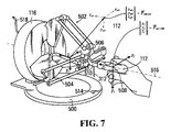
図7に右入力装置116をより詳細に示す。簡潔にするために、右入力装置116のみをさらに説明し、左入力装置118は同じように動作することが理解される。図7を参照して説明すると、入力装置116は、ベース500上に支持され、かつアーム502、504、および506を含む。右ハンドコントローラ112は、アーム502〜506に取り付けられて、デカルト基準フレーム(Cartesian reference frame)の直交軸x1、y1およびz1の位置決めおよび軸周りでの回転を可能にする。デカルト基準フレームは、ハンドコントローラ112の本体に沿って中ほどの点に起点を有し、および起点の位置は、ハンドコントローラ位置508を定義する(すなわち起点において)。この実施形態では、ハンドコントローラ112は、ジンバルマウント510に取り付けられる。アーム502〜506は、ハンドコントローラ112の動きを、従ってハンドコントローラ位置508を、図6に示すような半球形の入力装置作業空間内に留める。一実施形態では、入力装置116はまた、アーム502〜506を通してハンドコントローラ112に触覚フィードバックを提供するために、触力覚を生成するように構成され得る。
Input Device FIG. 7 shows the
入力装置116は複数のセンサー(図示せず)を有し、これらセンサーは、アーム502〜506のそれぞれの位置、ならびにx1、y1およびz1軸のそれぞれの周りでのハンドコントローラ112の回転を感知し、かつ入力装置のデカルト基準フレームxr、yr、zrに対する作業空間内でのハンドコントローラの位置およびハンドコントローラの回転向きを表現する信号を生じる。この実施形態では、位置信号および向き信号は、入力信号として、USB接続518を経由してワークステーションプロセッサ回路120のUSBインターフェース254へ送信される。
The
この実施形態では、ジンバルマウント510は、マウントから下方に延在するピン512を有し、およびベース500は、ピンを受け入れるためのキャリブレーション用開口部514を含む。ピン512が開口部514に受け入れられると、入力装置116は、入力装置のデカルト基準フレームxr、yr、zrに対して定義されるキャリブレーション位置に配置される。入力装置の基準フレームは、ベース500に対して平行なxr−zr平面およびベースに対して垂直なyr軸を有する。zr軸は、ベース500に対して平行であり、かつ入力装置116の中心を通る軸516と一致する。
In this embodiment, gimbal mount 510 has pins 512 extending down from the mount, and
入力装置116は、ハンドコントローラ112の現在の位置および向きを表現する現在のハンドコントローラ信号および現在のハンドコントローラ向き信号を生じる。それら信号は、現在のハンドコントローラ位置ベクトルおよび現在のハンドコントローラ回転行列によって表現され得る。現在のハンドコントローラ位置ベクトルは、

によって与えられる。現在のハンドコントローラ回転行列は、
によって与えられる。従って、行列RMCURRは、xr、yr、およびzr固定マスター基準フレームに対するハンドコントローラ112の現在の回転向きを定義する。現在のハンドコントローラ位置ベクトル
![]()
![]()
Given by The current hand controller rotation matrix is
Given by Thus, the matrix R MCURR defines the x r, y r, and z r current rotational direction of the
![]()
![]()
器械
図8に右側器械208を詳細に示す。図8を参照して説明すると、位置決め装置209は、ワークステーションプロセッサ回路120からの、通信インターフェース284において受信した制御信号に応答して、器械プロセッサ回路130の駆動制御インターフェース286が生じた駆動信号に応答して、器械マウント108にある様々な駆動部を稼働させることにより、手術作業空間内にエンドエフェクタ210を位置決めするように構成されている。駆動信号は、現在のハンドコントローラ位置ベクトル
![]()
![]()
器械208は、PCT/カナダ特許出願公開第2013/001076号明細書(これは本明細書に援用される)に説明されているような複数の同一の「椎骨部」550を含む。椎骨部550は、椎骨部を通過する制御ワイヤが位置決め装置209を動かすために伸ばされたりまたは収縮されたりするときに、互いに対して動くように動作可能である。エンドエフェクタ210の位置および向きは、軸xv、yv、およびzvを有する固定スレーブ基準フレームに対して定義され、これらの軸は、固定スレーブ基準位置552と呼ばれる点で交差する。固定スレーブ基準位置552は、器械208の縦軸554上にあり、および縦軸に対して垂直でありかつ挿入管202の遠位縁を含む平面に含まれる。
The
図示の実施形態では、エンドエフェクタ210はグリッパジョー216を含み、グリッパジョーは、エンドエフェクタ作業空間内に位置決めされかつ向きを決定され得る。グリッパジョー216の先端部は、エンドエフェクタデカルト基準フレームx2、y2、z2の起点として定義されるエンドエフェクタ位置560と指定され得る。エンドエフェクタ位置560は、スレーブ基準位置552に対して定義され、およびエンドエフェクタは、位置決め装置209および/またはエンドエフェクタ210を動かすために、固定スレーブ基準フレームxv、yv、zvに対して位置決めされかつ向きを決定され得る。
In the illustrated embodiment,
現在のハンドコントローラ位置信号
![]()
![]()
および3×3のエンドエフェクタ回転行列REENEWによって表現されている。
従って、REENEWは、xv、yv、およびzv固定スレーブ基準フレームに対するエンドエフェクタ作業空間のエンドエフェクタ210の新しい向きを定義する。ベクトル
![]()
![]()
![]()
And a 3 × 3 end effector rotation matrix R EENEW .
Thus, R EENEW is, x v, defines the y v, and z v new orientation of the
![]()
ベース設定プロセス
システム100が最初に起動するとき、ワークステーションプロセッサ回路120は、マスターベース位置ベクトル
![]()
![]()
![]()
![]()
図7に示す軸x1、y1およびz1によって表現されるハンドコントローラ112の基準フレームおよび軸xmb、ymb、およびzmb(同様に図7に示す)によって表現される定義可能なマスターベース基準フレームは、従って、システム100の起動時に一致する。図3に戻って説明すると、ワークステーションプロセッサ回路120は、定義可能なマスターベース位置ベクトル
![]()
![]()
システム100の起動時、新しいエンドエフェクタ位置ベクトル
![]()
![]()
![]()
![]()
![]()
![]()
![]()
![]()
従って、図8に示す軸x2、y2、およびz2によって表現されるエンドエフェクタ基準フレームおよび軸xsb、ysb、およびzsbによって表現される定義可能なスレーブベース基準フレームは、システム100の起動時に一致する。図3に戻って説明すると、ワークステーションプロセッサ回路120は、定義可能なスレーブベース位置ベクトル
![]()
![]()
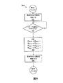
ベース設定プロセス(図4に示すプロセス300のブロック304)は、ブロック302において足踏みスイッチ134によって生じたイネーブル信号がアクティブ状態から非アクティブ状態へ移行するときに非同期的に実行される。ベース設定プロセス304のさらなる詳細を図9にプロセスフローチャートとして示す。ベース設定プロセス304はブロック600で開始し、ここで、ワークステーションプロセッサ回路120のマイクロプロセッサ250に指令して、動き制御インターフェース258を介して制御信号を送信し、制御信号により、器械プロセッサ回路130が駆動制御インターフェース286において、器械208のさらなる動きを生じないようにする駆動信号を生じるようにすることにより、器械208のさらなる動きを阻止する。一実施形態では、マイクロプロセッサ250は、同じ制御信号を維持し、および駆動制御インターフェース286によって生じる駆動信号が制御信号に応答して生じるため、駆動信号も、足踏みスイッチ134が押されたときにアクティブであった値に維持される。従って、器械208は、現在の位置および向きで不動のままとなる。
The base setting process (block 304 of
次いで、ブロック602は、マイクロプロセッサ250に指令して、イネーブル信号が非アクティブ状態からアクティブ状態へ再度移行されたかどうかを決定する。イネーブル信号が非アクティブ状態のままである場合、ブロック602は、マイクロプロセッサ250にブロック602を繰り返すように指令し、従って、イネーブル信号が非アクティブ状態にある間、プロセス304は実際上保留にされる。イネーブル信号が非アクティブ状態からアクティブ状態へ移行すると、ブロック602は、マイクロプロセッサ250をブロック604へ進める。
ブロック604は、マイクロプロセッサ250に指令して、それぞれハンドコントローラ112およびエンドエフェクタ210に対して新しいベース位置および向きを設定する。足踏みスイッチ134が押されている間、外科医は、ハンドコントローラ112を新しい箇所に動かして、手術作業空間に対して入力装置作業空間を再配置し得る。イネーブル信号がアクティブ状態へ移行すると、ブロック604は、マイクロプロセッサ250に、現在のハンドコントローラ位置ベクトル
![]()
![]()
![]()
![]()
![]()
![]()
![]()
![]()
次いで、ベース設定プロセス304は、ブロック606に進み、そこではマイクロプロセッサ250に指令し、134によって生じたイネーブル信号がアクティブなままである間、器械208のさらなる動きを可能にさせる。
The
従って、ベース設定プロセス304は、入力装置116のハンドコントローラ112が新しい箇所に動かされる間、足踏みスイッチ134を押すことによって器械208を不動にできるようにする。足踏みスイッチ134が解放されると、器械208の制御は、ハンドコントローラ112の新しい位置において再開する。従って、ハンドコントローラ112は、器械が不動のままである間に必要に応じて再位置決めされ得、患者に傷害を加え得る意図しない動きを防止する。
Accordingly, the
一実施形態では、足踏みスイッチ134がイネーブル信号を非アクティブ状態へ移行させるとき、それぞれ左および右の器械208および212の位置および向きを表現する図5のインジケータ408、412、410および414は、それらの現在のそれぞれの位置においてグラフィック描写136および138上で不動であり、および現在の入力装置110の入力を表現する追加的なインジケータ450および452が表示される。不動のインジケータ408、412、410および414は、不動の器械208および212の位置および向きを表現する一方、追加的なインジケータ450および452は、入力装置116および118およびハンドコントローラ112および114の現在の位置を表現する。それに続いて、イネーブル信号が再度アクティブ状態へ移行すると、追加的なインジケータ450および452が削除されるかまたは次第に消え、およびインジケータ408、412、410および414が再度アクティブにされる。足踏みスイッチ134を解放する前に、表示されるインジケータ408および450、ならびにインジケータ410および452を位置合わせすることにより、ハンドコントローラ112および114とそれぞれの器械208および212との間のオフセットを最小限にする。同様に、現在のハンドコントローラ回転インジケータ454および456は、エンドエフェクタ210および214の現在の回転を表現するインジケータからのオフセットで表示され得る。従って、足踏みスイッチ134が押されている間、ユーザは、ロール、向きおよび平行移動(XYZ)にオフセットを生じさせ得る。足踏みスイッチ134が解放されると、器械208および212は再係合され、およびロールおよび平行移動のオフセットが固定される。
In one embodiment, when
器械の位置および向き
器械の3D空間位置を計算するための、図3に示すプロセス300のブロック306のさらなる詳細を図10に示す。図10を参照して説明すると、プロセス306は、新しいエンドエフェクタ位置および向き制御信号
![]()
![]()
![]()
![]()
プロセス306はブロック630において開始し、そこではマイクロプロセッサ250に指令して、ワークステーションメモリ252の現在のバッファ320から、現在のハンドコントローラ位置ベクトル
![]()
![]()
![]()
![]()
![]()
![]()
![]()
![]()
新しいエンドエフェクタ位置信号
![]()
![]()
Aは、マスターとスレーブとの間の平行移動の動きの倍率を表現するスカラー値であり;
![]()
![]()
![]()
![]()
![]()
REENEWは、エンドエフェクタ210の現在の向きを表現する新しいエンドエフェクタ向き行列であり、および固定スレーブ基準位置552に対して定義され;
REEBASEは、非アクティブ状態からアクティブ状態へのイネーブル信号の最後の移行においてシフトされたエンドエフェクタ210の最後に保存された回転行列REENEWであり;
RMBASE −1は、回転行列RMBASEの逆行列であり、これは、非アクティブ状態からアクティブ状態へのイネーブル信号の最後の移行で保存されたハンドコントローラ112の最後に保存された回転行列RMCURRであり;および
RMCURRは、固定マスター基準フレームxr、yr、およびzrに対してハンドコントローラ112の向きを表現する現在取得された回転行列である)。
New end effector position signal
![]()
![]()
A is a scalar value representing the magnification of the translation movement between master and slave;
![]()
![]()
![]()
![]()
![]()
R EENEW is a new end effector orientation matrix that represents the current orientation of
R EEBASE is the last stored rotation matrix R EENEW of the
R MBASE -1 is the inverse of the rotation matrix R MBASE , which is the last stored rotation matrix R MCURR of the
次いで、ブロック634は、マイクロプロセッサ250に指令して、イネーブル信号がアクティブ状態にあるかどうかを決定する。イネーブル信号がアクティブ状態にある場合、ブロック636は、マイクロプロセッサ250に指令して、動き制御インターフェース258が、
![]()
![]()
次いで、ブロック638は、マイクロプロセッサ250に指令して、現在のバッファ320の記憶装置322および324に記憶された現在の位置ベクトル
![]()
![]()
![]()
![]()
![]()
![]()
![]()
![]()
![]()
![]()
![]()
![]()
![]()
![]()
ブロック634において、イネーブル信号が非アクティブ状態にある場合、マイクロプロセッサ250はブロック642に進められる。ブロック642は、マイクロプロセッサ250に指令して、動き制御インターフェース258が、ワークステーションメモリ252の以前のバッファ340のそれぞれの記憶装置346および348にある、
![]()
![]()
![]()
![]()
イネーブル信号が非アクティブに留まる間(すなわち足踏みスイッチ134が押されている間)、動き制御インターフェース258によって送信された制御信号は、イネーブル信号が非アクティブへ移行される前に有効であった以前に計算されたエンドエフェクタ位置および以前に計算された向き信号
![]()
![]()
別の実施形態では、イネーブル信号がブロック634においてアクティブ状態にあると決定されると、ブロック636を実行する前にいくつかの特別な機能が実行され得る。そのような特別な機能の一例は、本出願人の同時係属中の米国仮特許出願第62/101,734号明細書および同第62/101,804号明細書(それら全体が参照により本明細書に援用される)に説明されているようなアライメント制御機能である。例えば、一実施形態では、アライメント制御機能は、2つの結果の1つになり得る。第1の結果は、マイクロプロセッサ250に、ブロック636を実行するように指令してもよく、ここで、マイクロプロセッサに指令して、動き制御インターフェース258が器械プロセッサ回路130へ、新しく計算したエンドエフェクタ位置および新しく計算したエンドエフェクタ向き
![]()
![]()
![]()
![]()
従って、イネーブル信号が非アクティブ状態にあるとき、ハンドコントローラ112は、動かされかつ回転されることができ、かつ
![]()
![]()
ブロック636またはブロック638で生じたエンドエフェクタ位置ベクトル
![]()
![]()
運動制御信号
右側器械208を図11および図12において曲げたポーズで示す。左側器械212も、図12においてホーム構成に対応する直線ポーズで示す。図11および図12を参照して説明すると、器械208の位置決め装置209は、S字状セグメント700と呼ばれる第1の関節セグメントと、遠位セグメント702と呼ばれる第2の関節セグメントとを有する。これらセグメントは、それぞれ複数の椎骨部550を含む。S字状セグメント700は、挿入管202から、挿入距離qinsと呼ばれる距離をおいて開始し、この挿入距離は、固定スレーブベース基準フレームxv、yv、およびzvの起点において定義される固定スレーブ基準位置552と、第1の位置基準フレームx3、y3、およびz3の起点にある第1の位置704との間の距離である。挿入距離qinsは、挿入管202の端部から延出する、位置決め装置209の曲げることができない部分を表す。図示の実施形態では、挿入距離qinsは、約10〜20mmであり得るが、他の実施形態では、挿入距離は、それよりも長くてもまたは短くてもよく、例えば、0〜100mmで様々である。
Motion Control Signals The
S字状セグメント700は、第1の位置704から、軸x5、y5、およびz5を有する第3の基準フレームの起点として定義される第3の位置706へ延在し、かつS字状セグメント700内の制御ワイヤ(図示せず)が押されたり引かれたりするときに滑らかなS字形状を取ることができる。S字状セグメント700は、軸x4、y4、およびz4を有する第2の位置基準フレームの起点として定義される第2の位置708に中間点を有する。S字状セグメント700は、図12に最もよく示す、左側器械位置決め装置213に関する長さL1を有する。図示の実施形態では、長さL1は約65mmであり得る。
S-shaped
遠位セグメント702は、第3の位置706から、軸x6、y6、およびz6を有する第4の基準フレームの起点として定義される第4の位置710へ延在する。遠位セグメント702は、図12に最もよく示す、左側器械位置決め装置213に関する長さL2を有する。図示の実施形態では、長さL2は約23mmであり得る。
各エンドエフェクタ210および214はまた、エンドエフェクタ長さを有し、これは、図示の実施形態では、第4の位置710から、軸x2、y2、およびz2の起点として定義されるエンドエフェクタ先端部位置560まで延在するグリッパ長さL3である。グリッパ長さL3は、ここでも、左側器械位置決め装置213に関して図12に最もよく示し、および一実施形態では、約25mmであり得る。スレーブ基準位置552、第1の位置704、第2の位置708、第3の位置706、第4の位置710、およびエンドエフェクタ位置560は、集合的に器械基準位置と呼ばれ得る。
Each
PCT/カナダ特許出願公開第2013/001076号明細書(その全体が本明細書に援用される)に説明されるように、位置決め装置209および213内で制御ワイヤを押したり引いたりすることにより、位置決め装置209および213のS字状セグメント700は、図8に示す直線条件から、完全なS字形状までの図11および図12に示す右側器械208に関する部分的なS字形状まで、様々な度合いのS字形状に曲げられ得る。S字状セグメント700は、区分されており、第1のセクション712と、第2の位置708の反対側にある第2のセクション714とを有する。図5を参照して説明すると、第1および第2のセクション712および714は、第1の位置704、第2の位置708、および第3の位置706を含む第1の曲げ平面にある。第1の曲げ平面は、固定スレーブ基準フレームxv、yv、およびzvのxv−zv平面に対して角度δproxにある。第1のセクション712および第2のセクション714は、第1の曲げ平面において反対側であるが等しい角度θproxで曲げられ、いかなる角度θproxまたは曲げ平面角度δproxでも、第3の位置706のz5軸は、常に固定スレーブ基準位置552のzv軸に対して平行であり、かつそれと同じ方向に位置合わせされる。従って、位置決め装置209内で制御ワイヤを押したり引いたりすることにより、第3の位置706は、第1の位置704の周りのシリンダー状体積部内の空間内のいくつかの個別の位置のいずれかに配置され得る。このシリンダー状体積部は、S字状セグメント作業空間と称し得る。
By pushing and pulling control wires within the
さらに、遠位セグメント702は、第3の位置706および第4の位置710を含む第2の曲げ平面内にある。第2の曲げ平面は、固定スレーブ基準フレームxv、yv、およびzvのxv−zv平面に対して角度δdistにある。遠位セグメント702は、第2の曲げ平面において角度θdistに曲げられている。従って、位置決め装置209内で制御ワイヤを押したり引いたりすることにより、第4の位置710は、第4の位置710の周りの、空間内の別の体積部内に配置され得る。この体積部は、遠位作業空間と称し得る。S字状セグメント作業空間および遠位作業空間の組み合わせは、これが、位置決め装置209によって達成される器械208の発生し得る動き全体を表すため、位置決め装置作業空間と称し得る。左側器械212は、位置決め装置213によって同様に位置決めされ得る。
Further, the
第4の位置710とエンドエフェクタ位置560との間の距離は、図示の実施形態では、遠位セグメント702の可動部分とグリッパエンドエフェクタ210の先端部との間の距離であり、すなわち図12に示すグリッパ長さL3の長さである。一般的に、第4の位置710とエンドエフェクタ位置560との間のグリッパの一部分は曲げることができないであろう。
The distance between the
図示の実施形態では、エンドエフェクタ210は、エンドエフェクタ基準フレームx2−y2平面においてz2軸の周りで回転可能である可動グリッパジョー216を含み、回転角度は、x2正軸に対する角度γによって表わされる。最後に、グリッパジョー216は、完全な閉鎖から完全な開放までの様々な開放度合のいずれかであり得る(ジョーのヒンジ継手によって制限されるように)。様々な開放度合は、「グリッパ」と定義され得る。従って、要するに、運動制御信号は、以下の構成変数によって定義されるような位置決め装置209およびエンドエフェクタ210の運動学的構成に基づいて生成される:
qinsは、軸xv、yv、およびzvによって定義されるスレーブ基準位置552から、位置決め装置209のS字状セグメント700が開始する、軸x3、y3、およびz3によって定義される第1の位置704までの距離を表し;
δproxは、S字状セグメント700が固定スレーブ基準フレームのxv−yv平面に対して曲げられる第1の曲げ平面を表し;
θproxは、S字状セグメント700の第1および第2のセクション712および714が第1の曲げ平面において曲げられる角度を表し;
δdistは、遠位セグメント702が固定スレーブ基準フレームのxv−yv平面において曲げられる第2の曲げ平面を表し;
θdistは、第2の曲げで遠位セグメント702が曲げられる角度を表し;
γは、軸z2の周りでのエンドエフェクタ210の回転を表し;および
グリッパは、エンドエフェクタ210のグリッパジョー216のある度合の開放を表す(これは、ジョー216が閉鎖するように作動させるために、アクチュエータを握ることによってオペレータが加える圧力の量を示す、ハンドコントローラ112のアクチュエータ(図示せず)によって生じる信号に対して正比例で計算される値である)。
In the illustrated embodiment, the
q ins is defined by axes x 3 , y 3 , and z 3 where the S-shaped
[delta] prox represents a first bending plane S-shaped
θ prox represents the angle at which the first and
[delta] dist represents a second bend plane
θ dist represents the angle at which
γ represents the rotation of the
構成変数を計算するために、エンドエフェクタ回転行列REENEWが3×3の行列であることがまず想起される。
遠位セグメント702に関連付けられた値θdist、δdist、およびγは、式に従って計算され得る。
The values θ dist , δ dist , and γ associated with the
その後、第3の位置706は、固定スレーブ基準位置552から第3の位置へのベクトル
![]()
![]()
![]()
![]()
![]()
![]()
![]()
![]()
![]()
![]()
![]()
![]()
その後、固定スレーブ基準位置552から第3の位置706へのベクトル
![]()
![]()
式8bと式8aとの比を取ることにより、
![]()
![]()
を生じる。閉形式解は、θproxに関して見つけることができず、従って、θproxは、式8aまたは式8bのいずれかに対して数式の解を使用して見つけられる必要がある。例えば、ニュートン・ラフソン法が用いられ得、これは、実数値関数のより良好な根を連続して繰り返し概算する。ニュートン・ラフソン法は、以下の式を使用して実動化され得る。
![]()
式10は、式f(θprox)=0において書き換えられた式8aである。ニュートン・ラフソン法は、範囲0<θprox<πにおいて、関数は、大きい曲率半径を有し、かつ局所的な停留点を有しないため、非常に迅速に収束する傾向を有する。ニュートン・ラフソン法に続いて、以下の式を使用して式10を満たすために、θproxの改善された連続的な推定を繰り返し行い得る。
![]()
![]()
Is generated. A closed-form solution cannot be found for θ prox , so θ prox needs to be found using the solution of the equation for either equation 8a or 8b. For example, the Newton-Raphson method can be used, which successively and repeatedly estimates the better roots of a real-valued function. The Newton-Raphson method can be implemented using the following equation:
![]()
Expression 10 is Expression 8a rewritten in Expression f (θ prox ) = 0. The Newton-Raphson method tends to converge very quickly in the range 0 <θ prox <π since the function has a large radius of curvature and has no local stopping points. Following the Newton-Raphson method, an improved continuous estimation of θ prox may be performed repeatedly to satisfy Equation 10 using the following equation:
最後に、θproxを決定すると、以下の式を使用してqinsを見つけ得る。
![]()
![]()
![]()
![]()
![]()
![]()
![]()
![]()
上述の構成変数は、プロセス306のブロック636においてエンドエフェクタ位置信号および向き信号
![]()
![]()
![]()
![]()
3D空間位置決め
図3に示すプロセス300のブロック308のさらなる詳細を図13に示す。図13を参照して説明すると、プロセス308は、図5に示すグラフィック描写136および138を表示するための表示信号を生成するための、ワークステーションプロセッサ回路120によって実行されるコードのブロックを含む。プロセス308は、ブロック306において決定された構成変数の値を使用して、入力装置110および足踏みスイッチ134からの現在の入力に関して、手術作業空間において位置決め装置209に沿った点の箇所を決定する。複数の箇所が固定スレーブ基準位置552に対して手術作業空間内で決定される。プロセス308は、一般的に、基準点のそれぞれに関する理論的な個所、すなわち手術作業空間における第1の位置704、第2の位置708、第3の位置706、第4の位置710およびエンドエフェクタ位置560を決定することを含む。各基準点の理論的な個所が決定されると、手術作業空間内の、位置決め装置209に沿った様々な中間点の理論的な個所が決定され得る。位置決め装置209のS字状セグメント700、および遠位セグメント702のセクション712、714のそれぞれは、複数の椎骨部550を含み、および椎骨部の中心は、同じ距離だけ離間している。S字状セグメント700および遠位セグメント702は、曲げられると、滑らかで連続的な一定半径の湾曲を形成するため、各椎骨部の中心の理論的な個所は数学的に計算され得る。理論的な個所を使用して、器械プロセッサ回路130によって使用される運動制御信号を決定し、手術作業空間での器械208の実際の位置決めのための駆動信号を生成し得る。理論的な個所はまた、ワークステーションプロセッサ回路120によって使用されて、図5に示すグラフィック描写136および138を生成する。
3D Spatial Positioning Further details of
プロセス308はブロック740で開始し、ここで、マイクロプロセッサ250に指令して、処理のための第1の基準位置(図11において704で示す)を選択する。次いで、ブロック742は、マイクロプロセッサ250に指令して、長さqinsを有する位置決め装置209の曲げることができない部分だけ固定スレーブ基準位置552から離間している第1の位置704の箇所を決定する。従って、第1の位置704の箇所は、zv軸において固定スレーブ基準位置552にqins構成変数を単に加えることによって決定される。その箇所は、手術作業空間内の固定スレーブ基準位置552から第1の位置704までのベクトル
![]()
![]()
その後、ブロック744は、マイクロプロセッサ250に指令して、位置決め装置209の第1のセクション712に沿った中間点の箇所を決定する(すなわち第1の位置704と第2の位置708との間)。ブロック740において決定された第1の位置704の箇所を使用して、S字状セグメント700の第1のセクション712における全ての椎骨部の箇所を決定する。例えば、図11に示す実施形態では、第1の位置704と第2の位置708との間の第1のセクション712には15個の椎骨部550があると仮定し、n個目の椎骨部の中心は、第1の位置704に対して、
![]()
![]()
その後、ブロック746は、マイクロプロセッサ250に指令して、基準位置の全てが処理されたかどうかを決定し、および処理されていない場合、マイクロプロセッサは、ブロック748に進められ、そこで次の基準位置が処理のために選択される。その後、ブロック748は、マイクロプロセッサ250に指令して、ブロック742に戻らせ、および各基準位置に関してブロック742および744が繰り返される。
固定スレーブ基準位置552に対する第2の位置708の箇所は、構成変数qins、θprox、およびδproxから決定され得る。固定スレーブ基準位置552から第2の位置708までのベクトル
![]()
![]()
![]()
![]()
S字状セグメント700の端部における第3の位置706の箇所は、上述の式8a、8b、および8cで設定されるようなベクトル成分を有するベクトル
![]()
![]()
![]()
![]()
第4の位置710の箇所は、上記の式6a、6b、および6cにおいて設定されるようなベクトル成分を有する第3の位置706に対するベクトル
![]()
![]()
![]()
![]()
![]()
![]()
最後に、エンドエフェクタ位置560の理論的な個所は、上記の式7a、7bおよび7cにおいて設定されるようなベクトル成分の式による第4の位置710に対するベクトル
![]()
![]()
![]()
![]()
![]()
![]()
ブロック746において、位置決め装置209に沿った基準位置のそれぞれが処理された場合、209およびエンドエフェクタ210に沿った複数の点の箇所が決定されるため、手術作業空間における器械208の3D空間位置決めを定義する。
If each of the reference positions along the
その後、プロセス308はブロック748に進み、そこではマイクロプロセッサ250に指令して、位置決め装置208の現在の3D空間位置の二次元投影を生成して、図5のグラフィック描写136に示す位置決め装置を表現する領域412を生成する。ブロック748はまた、マイクロプロセッサ250に指令して、エンドエフェクタ210の現在の3D空間位置の二次元投影を生成して、図5に示すエンドエフェクタを表現するインジケータ408を生成する。一実施形態では、平面的な表現136が、xy−yv平面(すなわちzv軸に対して垂直な)と位置合わせされた平面に対して生成され、かつその投影は、位置決め装置209およびエンドエフェクタ210に沿った各中間点の位置のxv成分およびyv成分から生成される(すなわち、zv成分はゼロに設定されない)。
Thereafter, the
その後、プロセス308はブロック750に進み、そこではマイクロプロセッサ250に指令して、位置決め装置209のいずれかの投影部分が図5の境界406の近傍にあり、位置決め装置のさらなる動きに対する拘束がアクティブであることを示すかどうかを決定する。ブロック750はまた、マイクロプロセッサ250に指令して、エンドエフェクタ210のいずれかの投影部分が境界402の近傍にあるかどうかを決定する。これらの条件のいずれかが検出される場合、ブロック750は、マイクロプロセッサ250をブロック752に進める。
Thereafter,
ブロック752は、マイクロプロセッサ250に指令して、アクティブ拘束警告を生成する。一実施形態では、境界402または406の色または表示される強さを変更することにより、またはディスプレイ122上に警告シンボルを表示することにより可視警告が生成され得る。あるいは、警告は、インジケータ412および414の箇所にかぶせて、グラフィック描写136および138に表示され得る。他の実施形態では、可聴警告が生成され得る。代わりにまたは加えて、マイクロプロセッサ250は、入力装置110に、ハンドコントローラ112を介して触覚フィードバックを生成させるようにし得る。その後、ブロック752は、マイクロプロセッサ250に図4のブロック302に戻るように指令する。
ブロック750において、位置決め装置209およびエンドエフェクタ210がいずれの境界の近傍にもない場合、マイクロプロセッサ250は、図4のブロック302に戻るように指令される。
At
深さ
図5に示す器械深さ範囲416の描写は、以下の通り生成される。深さ範囲は、図6に示す軸492に沿って取られ、この範囲の端部424は、領域488内のエンドエフェクタ210の最大深さ494に対応する。器械深さ範囲416の端部426は、領域488内のエンドエフェクタ210の最小深さ496に対応する。入力装置深さ範囲432は、同様に、軸492に沿った、横線が引かれた領域482の部分に対応する。現在の深さインジケータ420は、エンドエフェクタ位置560のz値に対応する箇所において器械深さ範囲416上に位置決めされる。一実施形態では、マイクロプロセッサ250は、エンドエフェクタ210が入力装置深さ範囲の端部424または426のいずれかの近傍にあるとき、アクティブ拘束表示が生成されるようにし得る。警告は、可聴警告、ディスプレイ122に表示される可視警告、または右入力装置116およびハンドコントローラ112を通した触覚フィードバックの形態を取り得る。器械深さ範囲418は、同様に左側器械212に対して生成される。
Depth The depiction of the
回転
図5に示す器械回転範囲440は、構成変数γから生成される(すなわち、図11に示すような軸z2の周りでのエンドエフェクタ210の回転)。「Δ」インジケータは、エンドエフェクタ210の現在の回転角度γを表し、ここで、垂直線444は、一般的に非回転位置に保持されている右ハンドコントローラ112に対応する基準を取られる。一連の器械回転範囲440は、ハンドコントローラ112によってもたらされる回転範囲の程度に対応する程度を有する。器械回転範囲440はまた、入力装置作業空間と手術作業空間との間のマッピングに依存してオフセットされ得る。例えば、足踏みスイッチ134が押された後、ハンドコントローラ112は、足踏みスイッチ134を解放する前に回転され得るため、図5に示すように作業回転範囲をオフセットする。
位置決め装置のアクティブ拘束
説明されるように計算された右側器械208の位置決め装置209の中間位置は、手術作業空間(図5において484で示す)内の器械208の位置決め装置209の3D箇所を定義する。椎骨部550の各中間箇所に対し、マイクロプロセッサ250は、その箇所が手術作業空間484の3D境界面485の一部分の近傍にあるかどうかを決定する。器械208および212の位置決め装置209の複数の位置のグラフィック描写の例を図14に示す。図14を参照して説明すると、第1の例800は、挿入後の開始位置における器械208および212に関するグラフィック描写136および138を示し、そこでは、位置決め装置209および213は、器械の図の左側の側面図に示すように実質的に直線の位置にある。グラフィック描写136および138は、それぞれ中心に配置された点として位置決め装置209および213を示す。
Active Constraint of Positioning Device The intermediate position of the
次の例802では、位置決め装置209は上に動かされ、および位置決め装置213は下に動かされており、および804にある中間箇所は、境界面485の上方部分および下方部分の近傍となるようにマイクロプロセッサ250によって決定される。器械208および212を示すドットは、境界の近傍の箇所に示されている。警告が、境界の複数の部分を目立つ色に色付けして生成されて、外科医に状態を表示し得る。
In the next example 802, the
位置決め装置209および213の左限/右限の例が806に示されている。808に示す例では、位置決め装置209および213は、一般的に例806におけるように位置決めされるが、エンドエフェクタ210および214は外側に向けられている。エンドエフェクタ210および214は、図5に示す領域488の境界面489の近傍に配置され、かつそれぞれインジケータ408および410によって示される。位置決め装置209および210は、それぞれ領域412および414によって表現される。警告は、外科医に状態を示すために、境界面489において目立つ色の領域として生成されて示され得る。
An example of the left / right limits of the
例810は、エンドエフェクタインジケータ408および410および領域412および414が見えるように、わずかに向きを変えられた器械208および212を示す。例812では、エンドエフェクタ210および214は内側に向けられたままであるが、位置決め装置209および213は、814において示すように上限および下限に到達している。例816では、エンドエフェクタ210および214は外側に向けられ、かつそれぞれ3D境界面489の上方部分および下方部分の近傍にある。最終的な例818では、位置決め装置の動きに対する左限/右限に関する、例812に示すのと同様の状況が示されている。
Example 810 shows
具体的な実施形態を説明しかつ図示したが、そのような実施形態は本発明の説明にすぎず、添付の特許請求の範囲に従って構成されるような本発明の限定ではないと考慮されるべきである。 While specific embodiments have been described and illustrated, it is to be understood that such embodiments are merely illustrative of the invention and are not limiting of the invention, as configured in accordance with the appended claims. It is.
Claims (17)
プロセッサ回路が、前記入力装置から受信された現在の入力信号に関して、前記手術作業空間内での前記器械の現在の三次元空間位置を計算すること;
前記プロセッサ回路が、前記プロセッサ回路と通信するディスプレイに前記手術作業空間のグラフィック描写を表示するための表示信号を生成すること
を含み、前記グラフィック描写は、平面的な表現を含み、前記平面的な表現は、
前記手術作業空間内での前記器械の横方向の動きに対する限界を示す境界を有する器械移動領域;および
前記平面的な表現上への前記位置決め装置および前記エンドエフェクタの前記現在の空間位置の二次元投影
を含み、
前記方法は、
前記器械が前記器械移動領域の前記境界の近傍にあるという決定に応答して、前記プロセッサ回路に前記境界におけるアクティブ拘束表示を表示させることをさらに含む、方法。 A method for schematically representing a spatial position of an instrument used in a robotic surgical system, wherein the instrument includes an end effector, the end effector being generated by movement of a hand controller of the input device in the input device workspace. Responsive to the received input signal, the method is coupled to a positioning device for spatially positioning the end effector in a surgical workspace.
Processor circuitry for calculating a current three-dimensional spatial position of the instrument within the surgical workspace with respect to a current input signal received from the input device;
The processor circuit including generating a display signal for displaying a graphical depiction of the surgical workspace on a display in communication with the processor circuit, wherein the graphical depiction includes a planar representation; The expression is
An instrument movement area having a boundary indicating a limit to lateral movement of the instrument within the surgical workspace; and a two-dimensional of the current spatial position of the positioning device and the end effector on the planar representation. look including a projection,
The method comprises:
The method further comprising causing the processor circuit to display an active restraint indication at the boundary in response to a determination that the device is near the boundary of the device movement region .
プロセッサ回路が、前記入力装置から受信された現在の入力信号に関して、前記手術作業空間内での前記器械の現在の三次元空間位置を計算すること; Processor circuitry for calculating a current three-dimensional spatial position of the instrument within the surgical workspace with respect to a current input signal received from the input device;
前記プロセッサ回路が、前記プロセッサ回路と通信するディスプレイに前記手術作業空間のグラフィック描写を表示するための表示信号を生成すること The processor circuit generates a display signal for displaying a graphical depiction of the surgical workspace on a display in communication with the processor circuit.
を含み、前記グラフィック描写は、平面的な表現を含み、前記平面的な表現は、Wherein the graphic depiction comprises a planar representation, wherein the planar representation comprises:
前記手術作業空間内での前記器械の横方向の動きに対する限界を示す境界を有する器械移動領域;および An instrument movement area having a boundary indicating limits for lateral movement of the instrument within the surgical workspace; and
前記平面的な表現上への前記位置決め装置および前記エンドエフェクタの前記現在の空間位置の二次元投影 Two-dimensional projection of the current spatial position of the positioning device and the end effector on the planar representation
を含み、Including
前記グラフィック描写は、 The graphic depiction is
前記手術作業空間内への前記器械の軸方向の動きに対する限界を示す器械深さ範囲; An instrument depth range indicating limits for axial movement of the instrument into the surgical workspace;
前記器械深さ範囲内での前記エンドエフェクタの現在の深さを表現するインジケータ;および An indicator representing the current depth of the end effector within the instrument depth range; and
前記入力装置作業空間と前記手術作業空間との間の現在のマッピングに利用できる前記器械深さ範囲の一部分を表現する入力装置深さ範囲 An input device depth range representing a portion of the instrument depth range available for a current mapping between the input device workspace and the surgical workspace.
をさらに含み、Further comprising
前記方法は、 The method comprises:
前記エンドエフェクタが前記入力装置深さ範囲の端部の近傍にあるという決定に応答して、前記プロセッサ回路にアクティブ拘束表示を表示させることをさらに含む、方法。 The method further comprising causing the processor circuit to display an active restraint indication in response to a determination that the end effector is near an end of the input device depth range.
プロセッサ回路が、前記入力装置から受信された現在の入力信号に関して、前記手術作業空間内での前記器械の現在の三次元空間位置を計算すること; Processor circuitry calculating a current three-dimensional spatial position of the instrument within the surgical workspace with respect to a current input signal received from the input device;
前記プロセッサ回路が、前記プロセッサ回路と通信するディスプレイに前記手術作業空間のグラフィック描写を表示するための表示信号を生成すること The processor circuit generates a display signal for displaying a graphical depiction of the surgical workspace on a display in communication with the processor circuit.
を含み、前記グラフィック描写は、平面的な表現を含み、前記平面的な表現は、Wherein the graphic depiction comprises a planar representation, wherein the planar representation comprises:
前記手術作業空間内での前記器械の横方向の動きに対する限界を示す境界を有する器械移動領域;および An instrument movement area having a boundary indicating limits for lateral movement of the instrument within the surgical workspace; and
前記平面的な表現上への前記位置決め装置および前記エンドエフェクタの前記現在の空間位置の二次元投影 Two-dimensional projection of the current spatial position of the positioning device and the end effector on the planar representation
を含み、Including
前記方法は、 The method comprises:
前記プロセッサ回路においてイネーブル信号を受信することをさらに含み、前記イネーブル信号は、アクティブ状態および非アクティブ状態を有し、前記アクティブ状態は、前記入力信号に応答して前記器械の動きを可能にし、および前記非アクティブ状態は、前記器械の動きを阻止して、前記入力装置作業空間内での前記ハンドコントローラの再位置決めを容易にし、および前記方法は、 Further comprising receiving an enable signal at the processor circuit, the enable signal having an active state and an inactive state, wherein the active state allows movement of the instrument in response to the input signal; and The inactive state prevents movement of the instrument to facilitate repositioning of the hand controller within the input device workspace, and the method includes:
前記アクティブ状態から前記非アクティブ状態へ移行する前記イネーブル信号に応答して、前記プロセッサ回路に、前記エンドエフェクタの前記現在の空間位置の前記二次元投影からのオフセットとして、前記グラフィック描写上に現在のハンドコントローラ位置インジケータを表示するための表示信号を生成させること;および In response to the enable signal transitioning from the active state to the inactive state, the processor circuit instructs the processor circuit to display the current spatial position of the end effector on the graphical depiction as an offset from the two-dimensional projection. Generating a display signal for displaying a hand controller position indicator; and
前記非アクティブ状態から前記アクティブ状態へ移行する前記イネーブル信号に応答して、前記現在のハンドコントローラ位置インジケータの表示を停止すること Stopping the display of the current hand controller position indicator in response to the enable signal transitioning from the inactive state to the active state.
をさらに含む、方法。The method further comprising:
プロセッサ回路が、前記入力装置から受信された現在の入力信号に関して、前記手術作業空間内での前記器械の現在の三次元空間位置を計算すること; Processor circuitry for calculating a current three-dimensional spatial position of the instrument within the surgical workspace with respect to a current input signal received from the input device;
前記プロセッサ回路が、前記プロセッサ回路と通信するディスプレイに前記手術作業空間のグラフィック描写を表示するための表示信号を生成すること The processor circuit generates a display signal for displaying a graphical depiction of the surgical workspace on a display in communication with the processor circuit.
を含み、前記グラフィック描写は、平面的な表現を含み、前記平面的な表現は、Wherein the graphic depiction comprises a planar representation, wherein the planar representation comprises:
前記手術作業空間内での前記器械の横方向の動きに対する限界を示す境界を有する器械移動領域;および An instrument movement area having a boundary indicating limits for lateral movement of the instrument within the surgical workspace; and
前記平面的な表現上への前記位置決め装置および前記エンドエフェクタの前記現在の空間位置の二次元投影 Two-dimensional projection of the current spatial position of the positioning device and the end effector on the planar representation
を含み、Including
前記入力装置によって生じた前記入力信号は、前記ハンドコントローラの現在の回転を定義する回転信号を含み、前記回転信号は、前記手術作業空間内で前記エンドエフェクタの回転を引き起こすように動作可能であり、前記グラフィック描写は、 The input signal generated by the input device includes a rotation signal defining a current rotation of the hand controller, the rotation signal operable to cause rotation of the end effector within the surgical workspace. , The graphic depiction is:
前記器械の回転運動に対する限界を示す器械回転範囲; An instrument rotation range indicating a limit to the rotational movement of the instrument;
前記エンドエフェクタの現在の回転を表現するインジケータ;および An indicator representing the current rotation of the end effector; and
前記入力装置作業空間と前記手術作業空間との間の現在のマッピングに利用できる前記器械回転範囲の一部分を表現する入力装置回転範囲 An input device rotation range representing a portion of the instrument rotation range available for a current mapping between the input device workspace and the surgical workspace.
を含み、Including
前記方法は、 The method comprises:
前記プロセッサ回路においてイネーブル信号を受信することをさらに含み、前記イネーブル信号は、アクティブ状態および非アクティブ状態を有し、前記アクティブ状態は、前記入力信号に応答して前記器械の動きを可能にし、および前記非アクティブ状態は、前記器械の動きを阻止して、前記入力装置作業空間内での前記ハンドコントローラの再位置決めを容易にし、および前記方法は、 Further comprising receiving an enable signal at the processor circuit, the enable signal having an active state and an inactive state, wherein the active state allows movement of the instrument in response to the input signal; and The inactive state prevents movement of the instrument to facilitate repositioning of the hand controller within the input device workspace, and the method includes:
前記アクティブ状態から前記非アクティブ状態へ移行する前記イネーブル信号に応答して、前記プロセッサ回路に、前記エンドエフェクタの現在の回転を表現する前記インジケータからのオフセットとして、前記グラフィック描写上に現在のハンドコントローラ回転インジケータを表示するための表示信号を生成させること;および In response to the enable signal transitioning from the active state to the inactive state, the processor circuit provides the processor circuit with a current hand controller on the graphic depiction as an offset from the indicator representing the current rotation of the end effector. Generating a display signal for displaying a rotation indicator; and
前記非アクティブ状態から前記アクティブ状態へ移行する前記イネーブル信号に応答して、現在のハンドコントローラ回転インジケータの表示を停止すること Stopping the display of the current hand controller rotation indicator in response to the enable signal transitioning from the inactive state to the active state.
をさらに含む方法。The method further comprising:
前記平面的な表現上に前記三次元境界の二次元投影を生成すること
によって前記境界を生成することをさらに含む、前記境界を生成することを含む、請求項1から4のいずれか1項に記載の方法。 Generating the boundary, further comprising: defining a three-dimensional boundary in the surgical workspace; and generating the boundary by generating a two-dimensional projection of the three-dimensional boundary on the planar representation. 5. The method according to any one of the preceding claims, comprising:
前記入力装置から受信された現在の入力信号に関して、前記手術作業空間内での前記器械の現在の三次元空間位置を計算すること;
前記プロセッサ回路と通信するディスプレイに前記手術作業空間のグラフィック描写を表示するための表示信号を生成すること
を行うように動作可能に構成されたプロセッサ回路
を含み、
前記グラフィック描写は、平面的な表現を含み、前記平面的な表現は、
前記手術作業空間内での前記器械の横方向の動きに対する限界を示す境界を有する器械移動領域;および
前記平面的な表現上への前記位置決め装置および前記エンドエフェクタの前記現在の空間位置の二次元投影
を含み、
前記プロセッサ回路は、前記器械が前記器械移動領域の前記境界の近傍にあるという決定に応答して、前記境界にアクティブ拘束表示を表示するように動作可能に構成される、
装置。 An apparatus for schematically representing a spatial position of an instrument used in a robotic surgical system, the instrument including an end effector, wherein the end effector moves a hand controller of the input device in an input device workspace. Responsive to an input signal generated by the device, coupled to a positioning device for spatially positioning the end effector in a surgical workspace, wherein the device is a processor circuit;
Calculating a current three-dimensional spatial position of the instrument within the surgical workspace with respect to a current input signal received from the input device;
A processor circuit operably configured to generate a display signal for displaying a graphical depiction of the surgical workspace on a display in communication with the processor circuit ;
Before SL graphical representation includes a planar representation, the planar representation,
An instrument movement area having a boundary indicating a limit to lateral movement of the instrument within the surgical workspace; and a two-dimensional of the current spatial position of the positioning device and the end effector on the planar representation. look including a projection,
The processor circuit is operatively configured to display an active restraint indication at the boundary in response to a determination that the device is near the boundary of the device movement area.
apparatus.
前記手術作業空間内への前記器械の軸方向の動きに対する限界を示す器械深さ範囲;
前記器械深さ範囲内での前記エンドエフェクタの現在の深さを表現するインジケータ;および
前記入力装置作業空間と前記手術作業空間との間の現在のマッピングに利用できる前記器械深さ範囲の一部分を表現する入力装置深さ範囲
をさらに含む、請求項11に記載の装置。 The graphic depiction is
An instrument depth range indicating limits for axial movement of the instrument into the surgical workspace;
An indicator representing the current depth of the end effector within the instrument depth range; and a portion of the instrument depth range available for a current mapping between the input device workspace and the surgical workspace. The apparatus of claim 11 , further comprising an input device depth range to represent.
前記アクティブ状態から前記非アクティブ状態へ移行する前記イネーブル信号に応答して、前記エンドエフェクタの前記現在の空間位置の前記二次元投影からのオフセットとして、前記グラフィック描写上に現在のハンドコントローラ位置インジケータを表示するための表示信号を生成すること;および
前記非アクティブ状態から前記アクティブ状態へ移行する前記イネーブル信号に応答して、前記現在のハンドコントローラ位置インジケータの表示を停止すること
を行うように動作可能に構成される、請求項11に記載の装置。 The processor circuit is configured to be operable to receive an enable signal at the processor circuit, the enable signal having an active state and an inactive state, wherein the active state is responsive to the input signal. The movement of the instrument is enabled and the inactive state prevents movement of the instrument to facilitate repositioning of the hand controller within the input device workspace, and wherein the processor circuit includes:
In response to the enable signal transitioning from the active state to the inactive state, a current hand controller position indicator on the graphic depiction as an offset from the two-dimensional projection of the current spatial position of the end effector. Operable to generate a display signal for display; and to stop displaying the current hand controller position indicator in response to the enable signal transitioning from the inactive state to the active state. The apparatus according to claim 11 , wherein the apparatus is configured to:
前記器械の回転運動に対する限界を示す器械回転範囲;
前記エンドエフェクタの現在の回転を表現するインジケータ;および
前記入力装置作業空間と前記手術作業空間との間の現在のマッピングに利用できる前記器械回転範囲の一部分を表現する入力装置回転範囲
を含む、請求項11に記載の装置。 The input signal generated by the input device includes a rotation signal defining a current rotation of the hand controller, the rotation signal operable to cause rotation of the end effector within the surgical workspace. Yes, the graphic depiction is:
An instrument rotation range indicating a limit to the rotational movement of the instrument;
An indicator representing a current rotation of the end effector; and an input device rotation range representing a portion of the instrument rotation range available for a current mapping between the input device workspace and the surgical workspace. Item 12. The apparatus according to Item 11 .
前記アクティブ状態から前記非アクティブ状態へ移行する前記イネーブル信号に応答して、前記エンドエフェクタの現在の回転を表現する前記インジケータからのオフセットとして、前記グラフィック描写上に現在のハンドコントローラ回転インジケータを表示するための表示信号を生成すること;および
前記非アクティブ状態から前記アクティブ状態へ移行する前記イネーブル信号に応答して、現在のハンドコントローラ回転インジケータの表示を停止すること
を行うように動作可能に構成される、請求項15に記載の装置。 The processor circuit is configured to be operable to receive an enable signal at the processor circuit, the enable signal having an active state and an inactive state, wherein the active state is responsive to the input signal. The movement of the instrument is enabled and the inactive state prevents movement of the instrument to facilitate repositioning of the hand controller within the input device workspace, and wherein the processor circuit includes:
Displaying a current hand controller rotation indicator on the graphic depiction as an offset from the indicator representing the current rotation of the end effector in response to the enable signal transitioning from the active state to the inactive state. And responsive to the enable signal transitioning from the inactive state to the active state to stop displaying the current hand controller rotation indicator. 16. The device of claim 15 , wherein the device comprises:
前記入力装置から受信された現在の入力信号に関して、前記手術作業空間内での前記器械の現在の三次元空間位置を計算すること;
前記プロセッサ回路と通信するディスプレイに前記手術作業空間のグラフィック描写を表示するための表示信号を生成すること
を行うように指令し、
前記グラフィック描写は、平面的な表現を含み、前記平面的な表現は、
前記手術作業空間内での前記器械の横方向の動きに対する限界を示す境界を有する器械移動領域;および
前記平面的な表現上への前記位置決め装置および前記エンドエフェクタの前記現在の空間位置の二次元投影
を含み、
前記プロセッサ回路は、前記器械が前記器械移動領域の前記境界の近傍にあるという決定に応答して、前記境界にアクティブ拘束表示を表示するように動作可能に構成される、
コンピュータ可読媒体。 A computer-readable medium coded with code for instructing a processor circuit of a robotic surgical system to represent a spatial position of an instrument used in the robotic surgical system, the instrument including an end effector, The end effector is coupled to a positioning device for spatially positioning the end effector in a surgical workspace in response to an input signal generated by movement of a hand controller of the input device in the input device workspace; The code includes:
Calculating a current three-dimensional spatial position of the instrument within the surgical workspace with respect to a current input signal received from the input device;
Commanding to generate a display signal for displaying a graphical depiction of the surgical workspace on a display in communication with the processor circuit ;
Before SL graphical representation includes a planar representation, the planar representation,
An instrument movement area having a boundary indicating a limit to lateral movement of the instrument within the surgical workspace; and a two-dimensional of the current spatial position of the positioning device and the end effector on the planar representation. look including a projection,
The processor circuit is operatively configured to display an active restraint indication at the boundary in response to a determination that the device is near the boundary of the device movement area.
Computer readable medium.
Applications Claiming Priority (3)
| Application Number | Priority Date | Filing Date | Title |
|---|---|---|---|
| US201662280334P | 2016-01-19 | 2016-01-19 | |
| US62/280,334 | 2016-01-19 | ||
| PCT/CA2017/000011 WO2017124177A1 (en) | 2016-01-19 | 2017-01-19 | Graphical user interface for a robotic surgical system |
Related Child Applications (1)
| Application Number | Title | Priority Date | Filing Date |
|---|---|---|---|
| JP2020010525A Division JP6765021B2 (en) | 2016-01-19 | 2020-01-27 | Graphical user interface for robotic surgery system |
Publications (2)
| Publication Number | Publication Date |
|---|---|
| JP2019500945A JP2019500945A (en) | 2019-01-17 |
| JP6653387B2 true JP6653387B2 (en) | 2020-02-26 |
Family
ID=59361084
Family Applications (2)
| Application Number | Title | Priority Date | Filing Date |
|---|---|---|---|
| JP2018530517A Active JP6653387B2 (en) | 2016-01-19 | 2017-01-19 | Graphical user interface for robotic surgery systems |
| JP2020010525A Active JP6765021B2 (en) | 2016-01-19 | 2020-01-27 | Graphical user interface for robotic surgery system |
Family Applications After (1)
| Application Number | Title | Priority Date | Filing Date |
|---|---|---|---|
| JP2020010525A Active JP6765021B2 (en) | 2016-01-19 | 2020-01-27 | Graphical user interface for robotic surgery system |
Country Status (8)
| Country | Link |
|---|---|
| US (2) | US11504191B2 (en) |
| EP (1) | EP3380033A4 (en) |
| JP (2) | JP6653387B2 (en) |
| KR (2) | KR102518492B1 (en) |
| CN (3) | CN108463184B (en) |
| AU (2) | AU2017210349B2 (en) |
| CA (1) | CA3010896A1 (en) |
| WO (1) | WO2017124177A1 (en) |
Cited By (1)
| Publication number | Priority date | Publication date | Assignee | Title |
|---|---|---|---|---|
| JP2020062521A (en) * | 2016-01-19 | 2020-04-23 | タイタン メディカル インコーポレイテッドTitan Medical Inc. | Graphical user interface for robot surgery system |
Families Citing this family (55)
| Publication number | Priority date | Publication date | Assignee | Title |
|---|---|---|---|---|
| US8663220B2 (en) | 2009-07-15 | 2014-03-04 | Ethicon Endo-Surgery, Inc. | Ultrasonic surgical instruments |
| US11090104B2 (en) | 2009-10-09 | 2021-08-17 | Cilag Gmbh International | Surgical generator for ultrasonic and electrosurgical devices |
| US11871901B2 (en) | 2012-05-20 | 2024-01-16 | Cilag Gmbh International | Method for situational awareness for surgical network or surgical network connected device capable of adjusting function based on a sensed situation or usage |
| US9408622B2 (en) | 2012-06-29 | 2016-08-09 | Ethicon Endo-Surgery, Llc | Surgical instruments with articulating shafts |
| US10751108B2 (en) | 2015-09-30 | 2020-08-25 | Ethicon Llc | Protection techniques for generator for digitally generating electrosurgical and ultrasonic electrical signal waveforms |
| US10595930B2 (en) | 2015-10-16 | 2020-03-24 | Ethicon Llc | Electrode wiping surgical device |
| US11229471B2 (en) | 2016-01-15 | 2022-01-25 | Cilag Gmbh International | Modular battery powered handheld surgical instrument with selective application of energy based on tissue characterization |
| WO2017124170A1 (en) * | 2016-01-19 | 2017-07-27 | Titan Medical Inc. | Method and apparatus for positioning a workstation for controlling a robotic system |
| US10456193B2 (en) | 2016-05-03 | 2019-10-29 | Ethicon Llc | Medical device with a bilateral jaw configuration for nerve stimulation |
| CN107297399B (en) * | 2017-08-08 | 2018-10-16 | 南京埃斯顿机器人工程有限公司 | A kind of method of robot Automatic-searching bending position |
| US11911045B2 (en) | 2017-10-30 | 2024-02-27 | Cllag GmbH International | Method for operating a powered articulating multi-clip applier |
| US11801098B2 (en) | 2017-10-30 | 2023-10-31 | Cilag Gmbh International | Method of hub communication with surgical instrument systems |
| US20190125320A1 (en) | 2017-10-30 | 2019-05-02 | Ethicon Llc | Control system arrangements for a modular surgical instrument |
| US11132462B2 (en) | 2017-12-28 | 2021-09-28 | Cilag Gmbh International | Data stripping method to interrogate patient records and create anonymized record |
| US11744604B2 (en) | 2017-12-28 | 2023-09-05 | Cilag Gmbh International | Surgical instrument with a hardware-only control circuit |
| US11896322B2 (en) | 2017-12-28 | 2024-02-13 | Cilag Gmbh International | Sensing the patient position and contact utilizing the mono-polar return pad electrode to provide situational awareness to the hub |
| US11612444B2 (en) | 2017-12-28 | 2023-03-28 | Cilag Gmbh International | Adjustment of a surgical device function based on situational awareness |
| US10758310B2 (en) | 2017-12-28 | 2020-09-01 | Ethicon Llc | Wireless pairing of a surgical device with another device within a sterile surgical field based on the usage and situational awareness of devices |
| US11832899B2 (en) | 2017-12-28 | 2023-12-05 | Cilag Gmbh International | Surgical systems with autonomously adjustable control programs |
| US11786251B2 (en) | 2017-12-28 | 2023-10-17 | Cilag Gmbh International | Method for adaptive control schemes for surgical network control and interaction |
| US11166772B2 (en) | 2017-12-28 | 2021-11-09 | Cilag Gmbh International | Surgical hub coordination of control and communication of operating room devices |
| US11109866B2 (en) | 2017-12-28 | 2021-09-07 | Cilag Gmbh International | Method for circular stapler control algorithm adjustment based on situational awareness |
| US20190201113A1 (en) | 2017-12-28 | 2019-07-04 | Ethicon Llc | Controls for robot-assisted surgical platforms |
| US11896443B2 (en) | 2017-12-28 | 2024-02-13 | Cilag Gmbh International | Control of a surgical system through a surgical barrier |
| US11864728B2 (en) | 2017-12-28 | 2024-01-09 | Cilag Gmbh International | Characterization of tissue irregularities through the use of mono-chromatic light refractivity |
| US11818052B2 (en) | 2017-12-28 | 2023-11-14 | Cilag Gmbh International | Surgical network determination of prioritization of communication, interaction, or processing based on system or device needs |
| US11389164B2 (en) | 2017-12-28 | 2022-07-19 | Cilag Gmbh International | Method of using reinforced flexible circuits with multiple sensors to optimize performance of radio frequency devices |
| US11026751B2 (en) | 2017-12-28 | 2021-06-08 | Cilag Gmbh International | Display of alignment of staple cartridge to prior linear staple line |
| US11771487B2 (en) | 2017-12-28 | 2023-10-03 | Cilag Gmbh International | Mechanisms for controlling different electromechanical systems of an electrosurgical instrument |
| US11857152B2 (en) | 2017-12-28 | 2024-01-02 | Cilag Gmbh International | Surgical hub spatial awareness to determine devices in operating theater |
| US11534196B2 (en) | 2018-03-08 | 2022-12-27 | Cilag Gmbh International | Using spectroscopy to determine device use state in combo instrument |
| US11090047B2 (en) | 2018-03-28 | 2021-08-17 | Cilag Gmbh International | Surgical instrument comprising an adaptive control system |
| US10058396B1 (en) | 2018-04-24 | 2018-08-28 | Titan Medical Inc. | System and apparatus for insertion of an instrument into a body cavity for performing a surgical procedure |
| US11272931B2 (en) | 2019-02-19 | 2022-03-15 | Cilag Gmbh International | Dual cam cartridge based feature for unlocking a surgical stapler lockout |
| US10939970B2 (en) | 2019-05-22 | 2021-03-09 | Titan Medical Inc. | Robotic surgery system |
| EP3973540A1 (en) * | 2019-05-23 | 2022-03-30 | Intuitive Surgical Operations, Inc. | Systems and methods for generating workspace volumes and identifying reachable workspaces of surgical instruments |
| USD940736S1 (en) | 2019-11-20 | 2022-01-11 | Titan Medical Inc. | Display screen or portion thereof with a graphical user interface |
| US11812957B2 (en) | 2019-12-30 | 2023-11-14 | Cilag Gmbh International | Surgical instrument comprising a signal interference resolution system |
| US11684412B2 (en) | 2019-12-30 | 2023-06-27 | Cilag Gmbh International | Surgical instrument with rotatable and articulatable surgical end effector |
| US11937863B2 (en) | 2019-12-30 | 2024-03-26 | Cilag Gmbh International | Deflectable electrode with variable compression bias along the length of the deflectable electrode |
| US11786291B2 (en) | 2019-12-30 | 2023-10-17 | Cilag Gmbh International | Deflectable support of RF energy electrode with respect to opposing ultrasonic blade |
| US11759251B2 (en) | 2019-12-30 | 2023-09-19 | Cilag Gmbh International | Control program adaptation based on device status and user input |
| US11950797B2 (en) | 2019-12-30 | 2024-04-09 | Cilag Gmbh International | Deflectable electrode with higher distal bias relative to proximal bias |
| US11779329B2 (en) | 2019-12-30 | 2023-10-10 | Cilag Gmbh International | Surgical instrument comprising a flex circuit including a sensor system |
| US20210196363A1 (en) | 2019-12-30 | 2021-07-01 | Ethicon Llc | Electrosurgical instrument with electrodes operable in bipolar and monopolar modes |
| US11696776B2 (en) | 2019-12-30 | 2023-07-11 | Cilag Gmbh International | Articulatable surgical instrument |
| EP4307239A3 (en) * | 2019-12-30 | 2024-03-27 | Intuitive Surgical Operations, Inc. | Systems for indicating approach to an anatomical boundary |
| US11944366B2 (en) | 2019-12-30 | 2024-04-02 | Cilag Gmbh International | Asymmetric segmented ultrasonic support pad for cooperative engagement with a movable RF electrode |
| US20210196357A1 (en) | 2019-12-30 | 2021-07-01 | Ethicon Llc | Electrosurgical instrument with asynchronous energizing electrodes |
| US20210196362A1 (en) * | 2019-12-30 | 2021-07-01 | Ethicon Llc | Electrosurgical end effectors with thermally insulative and thermally conductive portions |
| US11660089B2 (en) | 2019-12-30 | 2023-05-30 | Cilag Gmbh International | Surgical instrument comprising a sensing system |
| US11779387B2 (en) | 2019-12-30 | 2023-10-10 | Cilag Gmbh International | Clamp arm jaw to minimize tissue sticking and improve tissue control |
| JP2022088805A (en) | 2020-12-03 | 2022-06-15 | 株式会社メディカロイド | Robot surgery system and display method |
| DE202021102512U1 (en) | 2021-05-07 | 2022-05-10 | Deutsches Zentrum für Luft- und Raumfahrt e.V. | Robotic telemanipulation system with adaptable degree of autonomy, use of a robotic telemanipulation system, autonomous medical robotic system |
| WO2023126770A1 (en) * | 2021-12-28 | 2023-07-06 | Auris Health, Inc. | Offscreen indicator viewer user interface |
Family Cites Families (34)
| Publication number | Priority date | Publication date | Assignee | Title |
|---|---|---|---|---|
| US5662111A (en) * | 1991-01-28 | 1997-09-02 | Cosman; Eric R. | Process of stereotactic optical navigation |
| US5279309A (en) | 1991-06-13 | 1994-01-18 | International Business Machines Corporation | Signaling device and method for monitoring positions in a surgical operation |
| US7789875B2 (en) * | 1998-02-24 | 2010-09-07 | Hansen Medical, Inc. | Surgical instruments |
| JP2001104333A (en) | 1999-10-07 | 2001-04-17 | Hitachi Ltd | Surgery support device |
| JP2002253574A (en) * | 2001-03-01 | 2002-09-10 | Hitachi Ltd | Operation support device |
| CN100557632C (en) * | 2001-12-07 | 2009-11-04 | 皇家飞利浦电子股份有限公司 | Be used for spatially strengthening the medical observation system and method for the structure that the image of making an uproar is arranged |
| US8010180B2 (en) * | 2002-03-06 | 2011-08-30 | Mako Surgical Corp. | Haptic guidance system and method |
| US7660623B2 (en) | 2003-01-30 | 2010-02-09 | Medtronic Navigation, Inc. | Six degree of freedom alignment display for medical procedures |
| CA2460119A1 (en) | 2004-03-04 | 2005-09-04 | Orthosoft Inc. | Graphical user interface for computer-assisted surgery |
| US7972298B2 (en) * | 2004-03-05 | 2011-07-05 | Hansen Medical, Inc. | Robotic catheter system |
| US8052636B2 (en) * | 2004-03-05 | 2011-11-08 | Hansen Medical, Inc. | Robotic catheter system and methods |
| US10258285B2 (en) * | 2004-05-28 | 2019-04-16 | St. Jude Medical, Atrial Fibrillation Division, Inc. | Robotic surgical system and method for automated creation of ablation lesions |
| US9789608B2 (en) | 2006-06-29 | 2017-10-17 | Intuitive Surgical Operations, Inc. | Synthetic representation of a surgical robot |
| US8398541B2 (en) * | 2006-06-06 | 2013-03-19 | Intuitive Surgical Operations, Inc. | Interactive user interfaces for robotic minimally invasive surgical systems |
| KR101258912B1 (en) * | 2005-06-06 | 2013-04-30 | 인튜어티브 서지컬 인코포레이티드 | Laparoscopic ultrasound robotic surgical system |
| US9266239B2 (en) * | 2005-12-27 | 2016-02-23 | Intuitive Surgical Operations, Inc. | Constraint based control in a minimally invasive surgical apparatus |
| US9089256B2 (en) * | 2008-06-27 | 2015-07-28 | Intuitive Surgical Operations, Inc. | Medical robotic system providing an auxiliary view including range of motion limitations for articulatable instruments extending out of a distal end of an entry guide |
| US8317745B2 (en) * | 2008-03-27 | 2012-11-27 | St. Jude Medical, Atrial Fibrillation Division, Inc. | Robotic catheter rotatable device cartridge |
| CA2728381C (en) | 2008-06-18 | 2014-09-23 | Engineering Services Inc. | Mri compatible robot |
| US8594841B2 (en) | 2008-12-31 | 2013-11-26 | Intuitive Surgical Operations, Inc. | Visual force feedback in a minimally invasive surgical procedure |
| US20100198200A1 (en) * | 2009-01-30 | 2010-08-05 | Christopher Horvath | Smart Illumination for Surgical Devices |
| US8418073B2 (en) * | 2009-03-09 | 2013-04-09 | Intuitive Surgical Operations, Inc. | User interfaces for electrosurgical tools in robotic surgical systems |
| EP2750620B1 (en) * | 2011-09-02 | 2017-04-26 | Stryker Corporation | Surgical instrument including a cutting accessory extending from a housing and actuators that establish the position of the cutting accessory relative to the housing |
| US9408606B2 (en) * | 2012-06-28 | 2016-08-09 | Ethicon Endo-Surgery, Llc | Robotically powered surgical device with manually-actuatable reversing system |
| DE202014010578U1 (en) | 2013-01-10 | 2016-01-07 | M.S.T. Medical Surgery Technologies Ltd. | Surgical control system |
| EP2951743B1 (en) * | 2013-02-04 | 2020-04-29 | Children's National Medical Center | Hybrid control surgical robotic system |
| JP6461082B2 (en) | 2013-03-13 | 2019-01-30 | ストライカー・コーポレイション | Surgical system |
| EP2928408B1 (en) * | 2013-03-15 | 2019-03-06 | St. Jude Medical International Holding S.à r.l. | Medical device navigation system |
| US9592095B2 (en) | 2013-05-16 | 2017-03-14 | Intuitive Surgical Operations, Inc. | Systems and methods for robotic medical system integration with external imaging |
| US20160074123A1 (en) * | 2013-05-31 | 2016-03-17 | Randall Bly | Surgery Pathway Guidance And Boundary System |
| CN109106392A (en) * | 2014-06-11 | 2019-01-01 | 佳能株式会社 | Image display device, display control unit and display control method |
| JP6290723B2 (en) * | 2014-06-23 | 2018-03-07 | 公立大学法人公立はこだて未来大学 | Surgery support device and surgery support system |
| WO2016077543A1 (en) * | 2014-11-13 | 2016-05-19 | Intuitive Surgical Operations, Inc. | User- interface control using master controller |
| CN108463184B (en) * | 2016-01-19 | 2021-08-13 | 提坦医疗公司 | Graphical user interface for robotic surgical system |
-
2017
- 2017-01-19 CN CN201780005500.6A patent/CN108463184B/en active Active
- 2017-01-19 CA CA3010896A patent/CA3010896A1/en active Pending
- 2017-01-19 AU AU2017210349A patent/AU2017210349B2/en active Active
- 2017-01-19 CN CN202110837736.4A patent/CN113456232A/en active Pending
- 2017-01-19 KR KR1020217015792A patent/KR102518492B1/en active IP Right Grant
- 2017-01-19 WO PCT/CA2017/000011 patent/WO2017124177A1/en active Application Filing
- 2017-01-19 CN CN202110837738.3A patent/CN113456233A/en active Pending
- 2017-01-19 US US15/780,593 patent/US11504191B2/en active Active
- 2017-01-19 JP JP2018530517A patent/JP6653387B2/en active Active
- 2017-01-19 EP EP17740924.0A patent/EP3380033A4/en active Pending
- 2017-01-19 KR KR1020187023785A patent/KR102258511B1/en active IP Right Grant
-
2020
- 2020-01-27 JP JP2020010525A patent/JP6765021B2/en active Active
- 2020-02-21 AU AU2020201255A patent/AU2020201255B2/en active Active
-
2022
- 2022-11-21 US US18/057,510 patent/US20230200918A1/en active Pending
Cited By (1)
| Publication number | Priority date | Publication date | Assignee | Title |
|---|---|---|---|---|
| JP2020062521A (en) * | 2016-01-19 | 2020-04-23 | タイタン メディカル インコーポレイテッドTitan Medical Inc. | Graphical user interface for robot surgery system |
Also Published As
| Publication number | Publication date |
|---|---|
| US11504191B2 (en) | 2022-11-22 |
| AU2020201255B2 (en) | 2020-08-13 |
| EP3380033A1 (en) | 2018-10-03 |
| JP2019500945A (en) | 2019-01-17 |
| AU2017210349B2 (en) | 2019-12-12 |
| WO2017124177A1 (en) | 2017-07-27 |
| CN113456232A (en) | 2021-10-01 |
| US20230200918A1 (en) | 2023-06-29 |
| CA3010896A1 (en) | 2017-07-27 |
| KR20180104047A (en) | 2018-09-19 |
| EP3380033A4 (en) | 2018-12-26 |
| JP6765021B2 (en) | 2020-10-07 |
| KR102518492B1 (en) | 2023-04-05 |
| CN108463184B (en) | 2021-08-13 |
| US20180353245A1 (en) | 2018-12-13 |
| AU2017210349A1 (en) | 2018-06-21 |
| CN108463184A (en) | 2018-08-28 |
| JP2020062521A (en) | 2020-04-23 |
| CN113456233A (en) | 2021-10-01 |
| KR20210064404A (en) | 2021-06-02 |
| AU2020201255A1 (en) | 2020-03-12 |
| KR102258511B1 (en) | 2021-05-31 |
Similar Documents
| Publication | Publication Date | Title |
|---|---|---|
| JP6653387B2 (en) | Graphical user interface for robotic surgery systems | |
| US11779419B2 (en) | Autonomous correction of alignment error in a master-slave robotic system | |
| CN111278350B (en) | Positioning a camera of a surgical robotic system to capture images within a patient's body cavity | |
| CN110279427B (en) | Collision avoidance during controlled movement of movable arm of image acquisition device and steerable device | |
| EP2967348B1 (en) | Intelligent positioning system | |
| CN113456238A (en) | Instrument collision detection and feedback | |
| JP2018508300A (en) | System and method for rendering on-screen identification of an instrument in a teleoperated medical system | |
| JP2018515198A (en) | Orientation mapping between master and slave when misaligned | |
| JP2018508301A (en) | System and method for on-screen identification of instruments in a teleoperated medical system | |
| CA2948719A1 (en) | Intelligent positioning system and methods therefore | |
| CN110662507A (en) | Robotic surgical system with automatic guidance | |
| JP2021151469A (en) | Method and apparatus for controlling continuum robot | |
| CN114521131A (en) | System and method for inter-arm registration |
Legal Events
| Date | Code | Title | Description |
|---|---|---|---|
| A621 | Written request for application examination |
Free format text: JAPANESE INTERMEDIATE CODE: A621 Effective date: 20180611 |
|
| A977 | Report on retrieval |
Free format text: JAPANESE INTERMEDIATE CODE: A971007 Effective date: 20190415 |
|
| A131 | Notification of reasons for refusal |
Free format text: JAPANESE INTERMEDIATE CODE: A131 Effective date: 20190521 |
|
| A521 | Request for written amendment filed |
Free format text: JAPANESE INTERMEDIATE CODE: A523 Effective date: 20190719 |
|
| A131 | Notification of reasons for refusal |
Free format text: JAPANESE INTERMEDIATE CODE: A131 Effective date: 20190813 |
|
| A521 | Request for written amendment filed |
Free format text: JAPANESE INTERMEDIATE CODE: A523 Effective date: 20191112 |
|
| TRDD | Decision of grant or rejection written | ||
| A01 | Written decision to grant a patent or to grant a registration (utility model) |
Free format text: JAPANESE INTERMEDIATE CODE: A01 Effective date: 20191126 |
|
| A601 | Written request for extension of time |
Free format text: JAPANESE INTERMEDIATE CODE: A601 Effective date: 20191223 |
|
| A61 | First payment of annual fees (during grant procedure) |
Free format text: JAPANESE INTERMEDIATE CODE: A61 Effective date: 20200127 |
|
| R150 | Certificate of patent or registration of utility model |
Ref document number: 6653387 Country of ref document: JP Free format text: JAPANESE INTERMEDIATE CODE: R150 |
|
| R250 | Receipt of annual fees |
Free format text: JAPANESE INTERMEDIATE CODE: R250 |
|
| R250 | Receipt of annual fees |
Free format text: JAPANESE INTERMEDIATE CODE: R250 |