JP6647601B2 - Gaming machine - Google Patents
Gaming machine Download PDFInfo
- Publication number
- JP6647601B2 JP6647601B2 JP2018165538A JP2018165538A JP6647601B2 JP 6647601 B2 JP6647601 B2 JP 6647601B2 JP 2018165538 A JP2018165538 A JP 2018165538A JP 2018165538 A JP2018165538 A JP 2018165538A JP 6647601 B2 JP6647601 B2 JP 6647601B2
- Authority
- JP
- Japan
- Prior art keywords
- game
- state
- control board
- reel
- main control
- Prior art date
- Legal status (The legal status is an assumption and is not a legal conclusion. Google has not performed a legal analysis and makes no representation as to the accuracy of the status listed.)
- Active
Links
- 230000007246 mechanism Effects 0.000 claims description 21
- 230000000694 effects Effects 0.000 description 485
- 238000000034 method Methods 0.000 description 381
- 230000008569 process Effects 0.000 description 366
- 238000012545 processing Methods 0.000 description 289
- 238000003825 pressing Methods 0.000 description 163
- 230000007704 transition Effects 0.000 description 88
- 230000001133 acceleration Effects 0.000 description 68
- 238000003780 insertion Methods 0.000 description 59
- 230000037431 insertion Effects 0.000 description 59
- 238000001514 detection method Methods 0.000 description 54
- 241000219109 Citrullus Species 0.000 description 49
- 235000012828 Citrullus lanatus var citroides Nutrition 0.000 description 49
- 239000002243 precursor Substances 0.000 description 40
- 230000008901 benefit Effects 0.000 description 38
- 230000002441 reversible effect Effects 0.000 description 38
- 238000004519 manufacturing process Methods 0.000 description 34
- 241000167854 Bourreria succulenta Species 0.000 description 29
- 235000019693 cherries Nutrition 0.000 description 29
- 230000008859 change Effects 0.000 description 27
- 238000010586 diagram Methods 0.000 description 26
- NJPPVKZQTLUDBO-UHFFFAOYSA-N novaluron Chemical group C1=C(Cl)C(OC(F)(F)C(OC(F)(F)F)F)=CC=C1NC(=O)NC(=O)C1=C(F)C=CC=C1F NJPPVKZQTLUDBO-UHFFFAOYSA-N 0.000 description 24
- 238000013461 design Methods 0.000 description 20
- 230000002844 continuous effect Effects 0.000 description 19
- 238000010924 continuous production Methods 0.000 description 17
- 230000001965 increasing effect Effects 0.000 description 16
- 230000007423 decrease Effects 0.000 description 15
- 230000009471 action Effects 0.000 description 14
- 230000006870 function Effects 0.000 description 13
- 238000003860 storage Methods 0.000 description 13
- 230000005856 abnormality Effects 0.000 description 11
- 230000005284 excitation Effects 0.000 description 10
- 238000002360 preparation method Methods 0.000 description 10
- 238000009826 distribution Methods 0.000 description 9
- 238000009987 spinning Methods 0.000 description 9
- 239000000758 substrate Substances 0.000 description 9
- 238000007726 management method Methods 0.000 description 8
- 238000012986 modification Methods 0.000 description 8
- 230000004048 modification Effects 0.000 description 8
- 238000004364 calculation method Methods 0.000 description 7
- 238000012423 maintenance Methods 0.000 description 7
- 238000012546 transfer Methods 0.000 description 7
- 230000003247 decreasing effect Effects 0.000 description 6
- 239000000463 material Substances 0.000 description 6
- 230000002829 reductive effect Effects 0.000 description 6
- 230000001960 triggered effect Effects 0.000 description 6
- 230000002159 abnormal effect Effects 0.000 description 5
- 239000008186 active pharmaceutical agent Substances 0.000 description 5
- 239000000872 buffer Substances 0.000 description 5
- 238000009877 rendering Methods 0.000 description 5
- 241001494479 Pecora Species 0.000 description 4
- 230000002730 additional effect Effects 0.000 description 4
- 238000005259 measurement Methods 0.000 description 4
- 238000011084 recovery Methods 0.000 description 4
- 230000001737 promoting effect Effects 0.000 description 3
- 229920005989 resin Polymers 0.000 description 3
- 239000011347 resin Substances 0.000 description 3
- 239000012536 storage buffer Substances 0.000 description 3
- 239000000126 substance Substances 0.000 description 3
- 229920003002 synthetic resin Polymers 0.000 description 3
- 239000000057 synthetic resin Substances 0.000 description 3
- XECAHXYUAAWDEL-UHFFFAOYSA-N acrylonitrile butadiene styrene Chemical compound C=CC=C.C=CC#N.C=CC1=CC=CC=C1 XECAHXYUAAWDEL-UHFFFAOYSA-N 0.000 description 2
- 229920000122 acrylonitrile butadiene styrene Polymers 0.000 description 2
- 239000004676 acrylonitrile butadiene styrene Substances 0.000 description 2
- 230000005540 biological transmission Effects 0.000 description 2
- 230000004397 blinking Effects 0.000 description 2
- 238000012790 confirmation Methods 0.000 description 2
- 230000001186 cumulative effect Effects 0.000 description 2
- 230000029087 digestion Effects 0.000 description 2
- 230000001976 improved effect Effects 0.000 description 2
- 230000014759 maintenance of location Effects 0.000 description 2
- 230000007257 malfunction Effects 0.000 description 2
- 239000000203 mixture Substances 0.000 description 2
- 238000012544 monitoring process Methods 0.000 description 2
- 239000004033 plastic Substances 0.000 description 2
- 229920003023 plastic Polymers 0.000 description 2
- 238000003672 processing method Methods 0.000 description 2
- 239000000047 product Substances 0.000 description 2
- 230000002250 progressing effect Effects 0.000 description 2
- 238000005070 sampling Methods 0.000 description 2
- 229910001369 Brass Inorganic materials 0.000 description 1
- RYGMFSIKBFXOCR-UHFFFAOYSA-N Copper Chemical compound [Cu] RYGMFSIKBFXOCR-UHFFFAOYSA-N 0.000 description 1
- 208000001613 Gambling Diseases 0.000 description 1
- BQCADISMDOOEFD-UHFFFAOYSA-N Silver Chemical compound [Ag] BQCADISMDOOEFD-UHFFFAOYSA-N 0.000 description 1
- 229910000831 Steel Inorganic materials 0.000 description 1
- 244000305550 Streptopus amplexifolius Species 0.000 description 1
- 238000013459 approach Methods 0.000 description 1
- 230000001174 ascending effect Effects 0.000 description 1
- 230000015572 biosynthetic process Effects 0.000 description 1
- 239000010951 brass Substances 0.000 description 1
- 239000003086 colorant Substances 0.000 description 1
- 238000004891 communication Methods 0.000 description 1
- 230000000295 complement effect Effects 0.000 description 1
- 230000008094 contradictory effect Effects 0.000 description 1
- 229910052802 copper Inorganic materials 0.000 description 1
- 239000010949 copper Substances 0.000 description 1
- 238000012937 correction Methods 0.000 description 1
- 230000000881 depressing effect Effects 0.000 description 1
- 238000011161 development Methods 0.000 description 1
- 239000010432 diamond Substances 0.000 description 1
- 238000007599 discharging Methods 0.000 description 1
- 238000006073 displacement reaction Methods 0.000 description 1
- 238000013073 enabling process Methods 0.000 description 1
- 230000002708 enhancing effect Effects 0.000 description 1
- 230000004438 eyesight Effects 0.000 description 1
- PCHJSUWPFVWCPO-UHFFFAOYSA-N gold Chemical compound [Au] PCHJSUWPFVWCPO-UHFFFAOYSA-N 0.000 description 1
- 239000010931 gold Substances 0.000 description 1
- 229910052737 gold Inorganic materials 0.000 description 1
- 238000011534 incubation Methods 0.000 description 1
- 230000001939 inductive effect Effects 0.000 description 1
- 230000007775 late Effects 0.000 description 1
- 239000004973 liquid crystal related substance Substances 0.000 description 1
- 239000002184 metal Substances 0.000 description 1
- 229910052751 metal Inorganic materials 0.000 description 1
- 238000000465 moulding Methods 0.000 description 1
- 230000002093 peripheral effect Effects 0.000 description 1
- 238000007747 plating Methods 0.000 description 1
- 230000002265 prevention Effects 0.000 description 1
- 230000004044 response Effects 0.000 description 1
- 230000000284 resting effect Effects 0.000 description 1
- 230000033764 rhythmic process Effects 0.000 description 1
- 230000000630 rising effect Effects 0.000 description 1
- 229910052709 silver Inorganic materials 0.000 description 1
- 239000004332 silver Substances 0.000 description 1
- 229910001220 stainless steel Inorganic materials 0.000 description 1
- 239000010935 stainless steel Substances 0.000 description 1
- 239000010959 steel Substances 0.000 description 1
- 238000003756 stirring Methods 0.000 description 1
- 239000013589 supplement Substances 0.000 description 1
- 230000001360 synchronised effect Effects 0.000 description 1
Images


Description
遊技機に関する。 Related to gaming machines.
回胴式遊技機(スロットマシン)は、所定数の遊技メダルを投入後に遊技開始指示装置(スタートレバー)が操作されたことを契機として1ゲームが開始されて、複数の図柄が外周上に配置された複数列の回胴(リール)が回転動作し、当該回転動作を停止させるための回胴停止装置(ストップボタン)を駆使して回胴を停止させた結果、有効ライン上に所定の図柄の組合せ(例えば「777」等の入賞役)が並んだ場合には、通常遊技状態よりも遊技者にとって利益状態の高い特別遊技状態(通常時よりも小役等の抽選確率が上昇する遊技状態)に移行するタイプのものが一般的である。ここで、回胴式遊技機においては、遊技の興趣性を高めるための演出用の画像等が、リールの回転動作及び停止動作とシンクロした形で、液晶等のディスプレイ上にて表示される場合があり、回胴停止装置等を操作した際に、回胴上に表示された図柄とディスプレイ上に表示された演出用の画像等とを見比べながら、遊技の結果を予測して楽しむよう構成されているものが多い。また、遊技機に何らかの異常が発生した場合には遊技の進行が停止するエラーとなり得るよう構成されているものも多い。また、近年のぱちんこ遊技機としては、遊技盤面(遊技領域)上の始動口に遊技球が入球したことを契機として所定確率の大当り抽選がなされ、当該大当り抽選に当選した場合には大当り(特別遊技)状態へと移行し、遊技盤面に備えられた大入賞口が開放して大量の賞球を獲得できるぱちんこ遊技機が主流である。このように構成されたぱちんこ遊技機の内には、当該大当り抽選における当選確率を上昇させる確率変動遊技状態や当該大当り抽選における抽選結果を報知するための図柄変動の効率を上昇させる時間短縮遊技状態等を備え、これら遊技状態によって遊技者にとって有利な遊技進行状態を創り出すことで遊技の興趣性を高める遊技機も存在している。 One game is started when a game start instruction device (start lever) is operated after a predetermined number of game medals are inserted, and a plurality of symbols are arranged on an outer periphery of a spinning-type gaming machine (slot machine). A plurality of rows of rotating drums (reels) are rotated, and the rotating drums are stopped by making full use of a rotating drum stopping device (stop button) for stopping the rotating movements. As a result, a predetermined symbol is displayed on the activated line. (For example, winning combinations such as "777") are arranged in a special gaming state in which the player has a higher profit state than in the normal gaming state (a gaming state in which the lottery probability of a small role, etc. is higher than in the normal state). ) Is common. Here, in the case of a spinning-type gaming machine, a case where an image for staging to enhance the interest of the game is displayed on a display such as a liquid crystal in a form synchronized with the rotation and stop operations of the reels. There is a configuration in which when operating a spine stop device or the like, a game result is predicted and enjoyed while comparing a symbol displayed on the spine with an image for staging displayed on a display. There are many things. In addition, many games are configured so that an error that stops the progress of the game can be caused when any abnormality occurs in the gaming machine. In recent years, as a pachinko gaming machine, a jackpot lottery with a predetermined probability is made when a game ball enters a starting port on a game board surface (game area), and when the jackpot lottery is won, the jackpot ( The game is shifted to a special game state, and the main game machine is a pachinko game machine in which a large winning prize hole provided on the game board surface is opened to obtain a large amount of prize balls. Among the pachinko gaming machines configured in this way, there is a probability varying gaming state in which the winning probability in the jackpot lottery is increased, and a time reducing gaming state in which the efficiency of symbol variation for notifying the lottery result in the jackpot lottery is increased. There are also gaming machines that have a game progress state that creates an advantageous game progress state for the player based on these game states, thereby increasing the interest of the game.
円滑に遊技を進行できる遊技機の提供が望まれている。 It is desired to provide a gaming machine that can smoothly play a game.
本態様に係る遊技機は、1ベットランプと、2ベットランプと、3ベットランプと、リプレイランプと、スタートランプと、遊技媒体投入可ランプと、遊技を開始するために操作されるスタートスイッチと、複数のリールと、前記複数のリールを含んだリールユニットと、前面が開口した遊技機筐体と、前記遊技機筐体の正面視における左側にヒンジ機構を介して連結され、開閉可能な前扉と、内部抽せん手段と、リールを制御するリール制御手段と、を備え、遊技区間として、第1区間と第2区間とを有しており、点灯することで第1区間であることを報知し得る第1区間表示器を有しており、第1区間におけるN回目(Nは自然数)の遊技であり、前記第1区間表示器が点灯している状況において、前記内部抽せん手段により所定の結果が決定され、その後、ベット数として3が設定され且つ遊技媒体の投入が可能な所定の状況で前記スタートスイッチの操作により実行された第1区間におけるN+1回目の遊技で第1区間の終了条件を満たす場合において、前記内部抽せん手段により特定の結果が決定され、複数のリールが回転している状況下では、前記リプレイランプは消灯しており、前記1ベットランプは点灯しており、前記2ベットランプは点灯しており、前記3ベットランプは点灯しており、前記スタートランプは消灯しており、前記遊技媒体投入可ランプは消灯しており、前記第1区間表示器は点灯しており、その後、当該特定の結果に対応する図柄組合せが停止された以降の第1のタイミングにおいては、前記リプレイランプは消灯しており、前記1ベットランプは点灯しており、前記2ベットランプは点灯しており、前記3ベットランプは点灯しており、前記スタートランプは消灯しており、前記遊技媒体投入可ランプは消灯しており、前記第1区間表示器は点灯しており、その後、前記リプレイランプを点灯した後の第2のタイミングにおいては、前記スタートランプは点灯しており、前記遊技媒体投入可ランプは点灯しており、前記第1区間表示器は消灯しており、前記遊技機筐体の内部には、前記リールユニットと、遊技媒体が貯蔵される主タンク部材と、前記主タンク部材の近傍に設置され、前記主タンク部材から溢れた遊技媒体を貯蔵するための補助タンク部材とが設けられており、前記主タンク部材の一部には、前記主タンク部材から前記補助タンク部材へ向かって下るスロープ部が設けられており、前記リールユニットは複数のネジ穴を有しており、前記複数のネジ穴のうち少なくとも2以上のネジ穴には導電性を有する係止部品が挿通されており、前記複数のネジ穴に挿通されている係止部品の中で、前記遊技機筐体の正面視における最も右側にある所定の係止部品の鉛直下方に前記補助タンク部材が配置されており、前記複数のネジ穴に挿通されている係止部品の中で、前記所定の係止部品とは異なる特定の係止部品の鉛直下方に前記スロープ部が配置されており、前記補助タンク部材が前記遊技機筐体の内部に設置されている状態において、前記補助タンク部材内に貯蔵された遊技媒体が満杯か否かを検知するための第1部材と第2部材とを少なくとも有しており、前記第1部材と前記第2部材との間の距離は前記所定の係止部品の長手方向の長さよりも長くなるよう構成されており、前記第1部材と前記第2部材との間の距離は前記特定の係止部品の長手方向の長さよりも長くなるよう構成されていることを特徴とする。
また、本態様に係る遊技機は、
リール基部(例えば、リール枠MW)の外周に巻き付けられた帯状のリールテープ(例えば、リール帯MO)を有し、
前記リールテープには、前記リールテープの長手方向に沿って複数種類の図柄が配置されており、
前記図柄の種類として、第1図柄(例えば、白セブン図柄)と、第2図柄(例えば、ベル図柄)と、を少なくとも有し、
前記第1図柄の最大横幅値は前記第2図柄の最大横幅値よりも大きく構成されており、
前記リールテープの長手方向における両端部の少なくとも何れか一方には前記第2図柄が配置されており、且つ前記リールテープの長手方向における両端部の各々には前記第1図柄が配置されておらず、
前記リールテープの長手方向における長さは、前記リール基部における前記リールテープが巻きつけられる面の外周よりも長いことを特徴とする態様であってもよい。
The gaming machine according to this aspect includes a 1-bet lamp, a 2-bet lamp, a 3-bet lamp, a replay lamp, a start lamp, a game medium insertable lamp, and a start switch operated to start a game. A plurality of reels, a reel unit including the plurality of reels, a gaming machine housing having an open front surface, and a hinged mechanism connected to a left side in a front view of the gaming machine housing via a hinge mechanism, so as to be openable and closable. The game machine includes a door, an internal drawer, and a reel controller that controls a reel. The game machine has a first section and a second section as game sections. A first section indicator that can be played, and in the N-th (N is a natural number) game in the first section, and in a situation where the first section indicator is lit, a predetermined value is set by the internal drawing means. result It is determined, and thereafter, the bet number is set to 3 and the end condition of the first section is satisfied in the (N + 1) th game in the first section executed by operating the start switch in a predetermined situation in which game media can be inserted. In some cases, the specific result is determined by the internal drawing means, and under a situation where a plurality of reels are rotating, the replay lamp is off, the 1-bet lamp is on, and the 2-bet lamp is on. Is on, the 3-bet lamp is on, the start lamp is off, the game media insertable lamp is off, the first section indicator is on, and At a first timing after the symbol combination corresponding to the specific result is stopped, the replay lamp is turned off and the one-bet run is not performed. Is lit, the two-bet lamp is lit, the three-bet lamp is lit, the start lamp is turned off, the game medium insertable lamp is turned off, the first The section indicator is lit, and thereafter, at a second timing after the replay lamp is lit, the start lamp is lit, the game medium insertable lamp is lit, and the first The section indicator is turned off, inside the gaming machine housing, the reel unit, a main tank member storing game media, and installed near the main tank member, from the main tank member An auxiliary tank member for storing overflowing game media is provided, and a slope portion descending from the main tank member to the auxiliary tank member is provided in a part of the main tank member. The reel unit has a plurality of screw holes, and at least two or more of the plurality of screw holes have a conductive locking component inserted therethrough. The auxiliary tank member is disposed vertically below a predetermined locking component on the rightmost side in a front view of the gaming machine housing among the locking components inserted through the holes, and the plurality of screw holes Among the locking components inserted through the slope portion, the slope portion is disposed vertically below a specific locking component different from the predetermined locking component, and the auxiliary tank member is provided in the gaming machine housing. In a state where it is installed inside, it has at least a first member and a second member for detecting whether or not the game medium stored in the auxiliary tank member is full, and the first member and The distance to the second member is the predetermined It is configured to be longer than the longitudinal length of the locking component, and the distance between the first member and the second member is configured to be longer than the longitudinal length of the specific locking component. It is characterized by having been done.
In addition, the gaming machine according to this aspect,
A belt-shaped reel tape (for example, a reel band MO) wound around an outer periphery of a reel base (for example, a reel frame MW);
On the reel tape, a plurality of types of symbols are arranged along a longitudinal direction of the reel tape,
The type of the symbol has at least a first symbol (for example, a white seven symbol) and a second symbol (for example, a bell symbol),
The maximum width value of the first symbol is configured to be larger than the maximum width value of the second symbol,
The second symbol is arranged on at least one of both ends in the longitudinal direction of the reel tape, and the first symbol is not arranged on each of both ends in the longitudinal direction of the reel tape. ,
The length in the longitudinal direction of the reel tape may be longer than the outer circumference of the surface of the reel base on which the reel tape is wound .
本態様に係る遊技機によれば、円滑に遊技を進行できる遊技機を提供することができる、という効果を奏する。 According to the gaming machine according to this aspect, it is possible to provide a gaming machine that can smoothly play a game.
はじめに、本明細書における各用語の意義について説明する。「乱数」とは、回胴式遊技機において何らかの遊技内容を決定するための抽選(電子計算機によるくじ)に使用される乱数であり、狭義の乱数の他に擬似乱数も含む(例えば、乱数としてはハード乱数、CPUを含む主制御チップによって生成された内蔵乱数、擬似乱数としてはソフト乱数)。例えば、遊技の結果に影響を与えるいわゆる「基本乱数」、具体的には、特別遊技に移行するための特別役や入賞役(小役、再遊技役)と関連した「当選乱数」、等を挙げることができる。「CPU」とは、当業界において周知であるものと同義であり、使用されているアーキテクチャ(CISC、RISC、ビット数等)や処理性能等には何ら限定されない。「電断(電源断)」とは、遊技機に設けられた電源スイッチの操作実行有無に係らず、遊技機に供給される電源電圧が一定レベル以下となったことを指し、例えば、電源供給ユニットの破損や停電等による不測の事態による電源供給の遮断をも包含する。「ROM」とは、当業界において周知であるものと同義であり、情報を物理的に保持する(例え
ば、データ読み出し用の電流を与えた場合、導通する素子構成であれば「1」、導通しない素子構成であれば「0」となる)。RAMとは、当業界において周知であるものと同義であり、情報を電気的に保持する(例えば、データ読み出し用の電流を与えた場合、蓄電されていれば「1」、蓄電されていなければ「0」となる。尚、RAM内で保持されているデータの一部又はすべてに対して、電断時にはバックアップ電源が供給されるよう構成されていることが一般的である)。「遊技状態」とは、例えば、遊技メダルが獲得容易であり遊技者にとって有利な特別遊技状態(いわゆる大当り遊技であり、ボーナス遊技や第1種BB・第2種BB等と呼ばれるものが該当する)、再遊技役の当選率があらかじめ定められた値である通常遊技状態よりも再遊技役の当選率が高い(又は低い)状態である再遊技確率変動遊技状態(RT状態)、当選した役を入賞させるためのリールの停止順、停止位置を報知し得るAT(アシストタイム)中状態、前記RT状態とAT中状態とが複合したART(アシストリプレイタイム)状態、等が挙げられる。また、通常遊技状態においても、RT状態、AT中状態、ART中状態への移行抽選確率が異なる、高確率通常遊技状態、低確率通常遊技状態、等(本例では、抽選状態と称している)が挙げられる。また、遊技状態は複合しても問題ない{更に、これらの遊技状態や機能(例えば、AT中状態への移行抽選や、リールの停止順に係る報知指示の出力等)は、遊技進行を制御する主制御基板側ですべて実装してしまっても問題ない}。また、本例においては、ATに関する状態とRT状態とを個別に記載し、RT状態が「RT1」且つATに関する状態が「通常遊技状態」等と称しているが、RT状態とATに関する状態とを纏めてARTに関する状態としてARTに関する状態が「通常遊技状態」等と称してもよい。「当選役」とは、内部抽選により当選した条件装置の種類(又は、条件装置番号)である。「報知状態」とは、後述する押し順ナビを実行可能なATに関する状態であり、リール停止順によって入賞する役が相違しないために押し順ナビが実行されない条件装置が当選したゲームであっても、ATに関する状態が押し順ナビを実行可能な状態であれば「報知状態」とするよう構成している。「カウンタ値」とは「報知遊技実行可能数」とも称し、後述する、AT残りゲーム数もしくはATカウンタM60のカウンタ値である。例えば、「報知遊技実行可能数」が1以上(「0」となった当該遊技も含めても良い)である場合には後述する押し順ナビが実行され得る。また、「報知遊技実行可能数」として、小役(主に、押し順ベル役)が当選したことに基づいて得られる遊技媒体の差枚数(払出し枚数から投入枚数を引いた枚数)や、押し順ベル役の当選回数、を採用しても良い。また、「特殊報知状態」とは、ATに関する状態のうち遊技者に最も有利となる状態であり、本例では、「上乗せ特化状態」と称している。また、「特定条件」とは、ATカウンタ値を減算し得る条件であり、例えば、1ゲームが終了した、所定役(例えば、押し順ベル役)が当選した、等が特定条件となる。「第1種特別役物」とは、規定数ごとの入賞に係る図柄の組合せの数を増加させ、又は規定数ごとの入賞に係る条件装置が作動する確率を上昇させる役物で、あらかじめ定められた場合に作動し12回を超えない回数の遊技の結果が得られるまで作動を継続することができるものであり、RB(レギュラーボーナス)と称することがある。「第1種特別役物連続作動装置」とは、第1種特別役物を連続して作動させることができる装置で、特定の図柄の組合せが表示された場合に作動しあらかじめ定められた場合に作動を終了するものであり、BB(ビッグボーナス)や第1種BBと称することがある。「第2種特別役物」とは、役抽選の結果に拘らず入賞に係る条件装置を作動させることとなる役物で、あらかじめ定められた場合に作動し1回の遊技の結果が得られた場合に作動を終了するものであり、CB(チャレンジボーナス)と称することがある。「第2種特別役物連続作動装置」とは、第2種特別役物を連続して作動させることができる装置で、特定の図柄の組合せが表示された場合に作動しあらかじめ定められた場合に作動を終了するものであり、MB(ミドルボーナス)や第2種BBと称することがある。「普通役物」とは、規定数毎の入賞に係る図柄の組合せの数を増加させ、又は、規定数毎の入賞に係る条件装置が作動する確率を上昇させる役物で、特定の図柄の組合せが表示された場合に作動し1回の遊技の結果が得られた場合に作動を終了することとされているものであり、SB(シングルボーナス)と称することがある。「オールJACINタイプ」とは、第1種BB役
が入賞した場合にJACINしたものとみなし、第1種BBの実行中においては常にRB中とする構成である。また、「JACIN抽選タイプ」とは、第1種BBの実行時にて非RB中とRB中とを繰り返し実行する構成である。また、「無制御リール」とは、停止操作を行った後に実行され得る引込み制御が実行されない状態のリールであり、停止操作を受け付けたリール位置から停止し得る最も近いリール位置にて停止する状態のリールである。「オールCBタイプ」とは、第2種BBの実行時にて常にCB中となる構成である。「CB移行抽選タイプ」とは、第2種BBの実行時にて非CB中とCB中とを繰り返し実行する構成である。
First, the meaning of each term in the present specification will be described. The "random number" is a random number used in a lottery (lot by an electronic computer) for determining some game content in a spinning-type gaming machine, and includes not only a random number in a narrow sense but also a pseudo-random number (for example, as a random number Is a hard random number, a built-in random number generated by a main control chip including a CPU, and a soft random number as a pseudo random number. For example, a so-called “basic random number” that affects the result of a game, specifically, a “winning random number” associated with a special role or a prize role (small role, replaying role) for shifting to a special game, and the like. Can be mentioned. The “CPU” has the same meaning as that known in the art, and is not limited in any way by the architecture (CISC, RISC, number of bits, etc.) or processing performance used. “Power interruption (power interruption)” means that the power supply voltage supplied to the gaming machine has fallen below a certain level irrespective of whether or not the power switch provided on the gaming machine is operated. This also includes shutting off the power supply due to an unforeseen situation such as damage to the unit or power failure. The “ROM” is synonymous with one known in the art, and physically holds information (for example, “1” if an element configuration is conductive when a current for reading data is given, If the element configuration is not used, it is "0"). A RAM is synonymous with one known in the art, and holds information electrically (for example, when a current for reading data is given, “1” is stored if stored, and if not stored, This is set to “0.” In general, backup power is supplied to part or all of the data held in the RAM when power is cut off.) The “game state” corresponds to, for example, a special game state in which a game medal is easily obtained and advantageous to the player (a so-called big hit game, which is referred to as a bonus game, a first type BB, a second type BB, or the like). ), The replaying probability varying game state (RT state) in which the replaying game winning rate is higher (or lower) than the normal gaming state in which the replaying game winning rate is a predetermined value. , An AT (assist time) state in which the stop order of the reels for notifying the reels and the stop position can be reported, and an ART (assist replay time) state in which the RT state and the AT state are combined. Also in the normal gaming state, the high-probability normal gaming state, the low-probability normal gaming state, and the like, which have different lottery probabilities from the RT state, the AT state, and the ART state, are referred to as the lottery state. ). There is no problem even if the game states are combined. Furthermore, these game states and functions (for example, a lottery transition to the AT-in-progress state, output of a notification instruction related to the reel stop order, and the like) control the game progress. There is no problem even if all are mounted on the main control board side. Further, in this example, the state relating to the AT and the RT state are described separately, and the RT state is referred to as "RT1" and the state relating to the AT is referred to as "normal game state". May be collectively referred to as an ART-related state, and a state relating to the ART may be referred to as a “normal gaming state” or the like. The “winning combination” is the type (or condition device number) of the condition device won by the internal lottery. The “notification state” is a state relating to an AT capable of executing a push order navigation described later, and even if the condition device in which the push order navigation is not executed because the winning combination does not differ according to the reel stop order is a game that has been won. If the state related to the AT is a state in which the push order navigation can be executed, the state is set to the “notification state”. The “counter value” is also referred to as the “available number of notification games”, and is the AT remaining game number or the counter value of the AT counter M60, which will be described later. For example, when the “available number of notification games” is 1 or more (this game including “0” may be included), a push order navigation described later can be executed. In addition, as the “number of notification game executable numbers”, the difference number of game media (the number of payouts minus the number of inserts) obtained based on the winning of the small role (mainly the push bell), The number of wins of the role of the forward bell may be adopted. The “special notification state” is the state that is most advantageous to the player among the states related to the AT, and is referred to as “additional specialization state” in this example. The “specific condition” is a condition under which the AT counter value can be decremented. For example, the specific condition is that one game is completed, a predetermined combination (for example, a pressing order bell combination) is won, and the like. "
尚、本実施形態は、あくまで一例であり、各手段が存在する場所や機能等、各種処理に関しての各ステップの順序、フラグのオン・オフのタイミング、各ステップの処理を担う手段名等に関し、以下の態様に限定されるものではない。また、上記した実施形態や変更例は、特定のものに対して適用されると限定的に解すべきでなく、どのような組み合わせであってもよい。例えば、ある実施形態についての変更例は、別の実施形態の変更例であると理解すべきであり、また、ある変更例と別の変更例が独立して記載されていたとしても、当該ある変更例と当該別の変更例を組み合わせたものも記載されていると理解すべきである。 Note that the present embodiment is merely an example, and the order of each step in various processes, the timing of turning on / off a flag, the name of a unit responsible for the processing of each step, and the like are described as an example. It is not limited to the following embodiments. In addition, it should not be understood that the above-described embodiments and modified examples are applied to specific ones in a limited manner, and any combination may be used. For example, it should be understood that a modification example of one embodiment is a modification example of another embodiment, and even if a certain modification example and another modification example are described independently, the modification example It should be understood that combinations of the modifications and the other modifications are also described.
(本実施形態)
ここで、各構成要素について説明する前に、本実施形態に係る回胴式遊技機Pの特徴(概略)を説明する。以下、図面を参照しながら、各要素について詳述する。
(This embodiment)
Here, before describing each component, the features (outline) of the turning-type gaming machine P according to the present embodiment will be described. Hereinafter, each element will be described in detail with reference to the drawings.
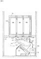
まず、図1(一部の構成については図2)を参照しながら、本実施形態に係る回胴式遊技機Pの前面側の基本構造を説明する。回胴式遊技機Pは、主に前扉(フロントドアとも称す)と、裏箱(キャビネット、基体とも称す)と裏箱内に設置されたリールユニット、ホッパ装置、電源供給ユニットE、主制御基板M(CPUMCを含む主制御チップCが搭載されている基板)、副制御基板S(CPUSCを含む副制御チップSCが搭載されている基板)で構成される。以下、これらを順に説明する。 First, a basic structure on the front side of a spinning-type gaming machine P according to the present embodiment will be described with reference to FIG. The spinning-type gaming machine P mainly includes a front door (also referred to as a front door), a back box (also referred to as a cabinet and a base), a reel unit installed in the back box, a hopper device, a power supply unit E, and a main control. A board M (a board on which the main control chip C including the CPUMC is mounted) and a sub-control board S (a board on which the sub-control chip SC including the CPUSC is mounted). Hereinafter, these will be described in order.
<前扉DU>
前扉DUは、遊技状態を視認可能にするための機構、遊技媒体の入力を可能にするための機構、リールユニットを操作するための機構、その他の機構等を含む。具体的には、遊技状態を視認可能にするための機構として、リール窓D160、投入数表示灯D210、スタートランプD180、再遊技ランプD290、投入可能ランプD300、特別遊技状態表示装置D250、クレジット数表示装置D200、払出数表示装置(押し順表示装置)D270(押し順表示装置D270と称することもある)、ATカウンタ値表示装置D280、有利区間表示器YH等が取り付けられている。また、遊技媒体の投入や賭け数(ベット数)の入力を可能にするための機構として、メダル投入口D170、ベットボタンD220、投入された遊技媒体の払い出しを可能にするための機構として、精算ボタンD60が取り付けられている。そして、リールを操作するための機構として、スタートレバーD50、停止ボタンD40が取り付けられている。なお、本実施形態における回胴式遊技機は、スタートレバーD50、停止ボタンD40、メダル投入口D170、ベットボタンD220、精算ボタンD60、サブ入力ボタンSB、十字キーSB2等が取り付けられている遊技者側にせり出した形状の操作卓を備えている。以下、各要素について詳述する。
<Front door DU>
The front door DU includes a mechanism for visually recognizing a game state, a mechanism for enabling input of a game medium, a mechanism for operating a reel unit, other mechanisms, and the like. Specifically, as a mechanism for making the game state visually recognizable, a reel window D160, an insertion number display lamp D210, a start lamp D180, a re-game lamp D290, an insertion possible lamp D300, a special game state display device D250, a credit number A display device D200, a payout number display device (push order display device) D270 (sometimes referred to as a push order display device D270), an AT counter value display device D280, an advantageous section display YH, and the like are attached. Also, as a mechanism for enabling the insertion of game media and input of the number of bets (the number of bets), a mechanism for enabling a medal slot D170, a bet button D220, and a payout of inserted game media, Button D60 is attached. As a mechanism for operating the reel, a start lever D50 and a stop button D40 are attached. The spinning-type gaming machine according to the present embodiment has a start lever D50, a stop button D40, a medal slot D170, a bet button D220, a settlement button D60, a sub input button SB, a cross key SB2, and the like. It has a console that protrudes to the side. Hereinafter, each element will be described in detail.
<遊技状態を視認可能にするための機構>
次に、遊技状態を視認可能にするための機構の要部について説明する。リール窓D160は、前扉DUの一部を構成する合成樹脂等によって形成された透明な部材であり、リール窓D160を通して遊技機枠内に設置されたリールユニットを視認可能に構成されてい
る。また、投入数表示灯D210は、3つのLEDによって構成されており、現在ベット(一の遊技を開始するために必要な遊技メダルを投入すること)されているメダル数と同数のLEDが点灯するよう構成されている。具体的には、投入数表示灯D210は、1ベットランプD211、2ベットランプD212、3ベットランプD213の3つのLED(ランプ)によって構成されており、ベットされている遊技メダルが1枚である場合には1ベットランプD211:点灯、2ベットランプD212:消灯、3ベットランプD213:消灯となり、ベットされている遊技メダルが2枚である場合には1ベットランプD211:点灯、2ベットランプD212:点灯、3ベットランプD213:消灯となり、ベットされている遊技メダルが3枚である場合には1ベットランプD211:点灯、2ベットランプD212:点灯、3ベットランプD213:点灯となる(再遊技が停止表示した次ゲームにおいてはその限りではなく、詳細は後述する)。また、スタートランプD180は、LEDによって構成されており、スタートレバーD50の操作が有効(操作を受け付けている)である場合に点灯し、スタートレバーD50の操作が無効(操作を受け付けていない)である場合に消灯するよう構成されている。また、再遊技ランプD290は、LEDによって構成されており、再遊技が停止表示したことを契機として点灯し、再遊技が停止表示した次回の遊技が終了したことによって消灯するよう構成されている。また、投入可能ランプD300は、メダル投入口D170への遊技メダルの投入が有効である、又は、ベットボタンD220の操作が有効である場合に点灯(点滅としてもよい)し、遊技メダルの投入が無効である、又は、ベットボタンD220の操作が無効である場合に消灯するよう構成されている。また、特別遊技状態表示装置D250は、7セグメントディスプレイによって構成されており、特別遊技中に払い出された払出数の総数が表示されるよう構成されている。尚、特別遊技状態表示装置D250を設けない構成としてもよく、そのように構成した場合には、後述する演出表示装置S40(第二情報表示部とも称することがある)にて当該払出数の総数を表示するよう構成することで遊技者は特別遊技中に払い出された払出数の総数を認識することができユーザーフレンドリーな遊技機とすることができる。また、クレジット数表示装置D200は、7セグメントディスプレイによって構成されており、遊技者の持ちメダルとして遊技機内に貯留されているメダル数の総数(クレジット数)が表示されるよう構成されている。また、払出数表示装置(押し順表示装置)D270は、7セグメントディスプレイによって構成されており、現在払出されている遊技メダル数及びリール停止順(左停止ボタンD41、中停止ボタンD42、右停止ボタンD43の停止順)によって入賞する役が相違し得る条件装置{いわゆる押し順役(押し順あり役とも称することがある)であるが、入賞する役や停止表示される図柄組合せが相違した場合には、遊技者に付される利益率(払出枚数、その後のRT状態等)が異なり得るよう構成されているものが一般的である}が成立したゲームにて、遊技者に最も有利となるリール停止順を報知し得るよう構成されている(当該報知を押し順ナビと称することがある)。このように、払出数表示装置(押し順表示装置)D270は、現在払出されている遊技メダル数と遊技者に最も高利益となるリール停止順との2つの表示を実行し得るよう構成されており、実行されている表示が2つの表示のうちいずれであるかを遊技者が誤認しないような表示態様となっており、当該表示態様の詳細は後述することとする。また、ATカウンタ値表示装置D280は、ATに関する状態(詳細は後述する)のうち、押し順表示装置D270(第一情報表示部とも称することがある)に表示された押し順ナビ表示に従って遊技を進行した場合に保障されることとなる遊技者にとって有利なATに関する状態(本例では、押し順ナビ状態、報知遊技とも称することがあり詳細は後述する)に滞在し得るゲーム数を表示し得るよう構成されている。尚、ATカウンタ値表示装置D280を設けない構成としてもよく、そのように構成した場合には、AT中状態に滞在し得るゲーム数を演出表示装置S40にて表示するよう構成することで遊技者は当該有利なATに関する状態が保障されているゲーム数を認識することができユーザーフレンドリーな遊技機とすることができる。尚、払出数表示装置(押し順表示装置)D270は、払出数表示装置と押し順表示装置との2つの装置に分けるよう構成してもよい。
<Mechanism for making the game state visible>
Next, a description will be given of a main part of a mechanism for making the game state visible. The reel window D160 is a transparent member formed of a synthetic resin or the like that forms a part of the front door DU, and is configured so that the reel unit installed in the gaming machine frame can be visually recognized through the reel window D160. The insertion number display light D210 is configured by three LEDs, and the same number of LEDs as the number of medals currently bet (inserting a game medal required to start one game) are lit. It is configured as follows. Specifically, the insertion number display lamp D210 is configured by three LEDs (lamp) of a 1-bet lamp D211, a 2-bet lamp D212, and a 3-bet lamp D213, and one game medal is bet. In this case, the 1-bet lamp D211: lights up, the 2-bet lamp D212: turns off, and the 3-bet lamp D213: turns off. : ON, 3 bet lamp D213: OFF, and if there are three game medals bet, 1BET lamp D211: ON, 2BET lamp D212: ON, 3BET lamp D213: ON (re-game) This is not the case with the next game in which is stopped and displayed, and details will be described later). The start lamp D180 is configured by an LED. The start lamp D180 is lit when the operation of the start lever D50 is valid (operation is received), and the operation of the start lever D50 is invalid (operation is not received). It is configured to turn off the light in a certain case. Further, the re-game lamp D290 is configured by an LED, and is turned on when the re-game is stopped and displayed, and turned off when the next game in which the re-game is stopped is completed. The insertable lamp D300 is turned on (or may blink) when the insertion of a game medal into the medal insertion slot D170 is effective or the operation of the bet button D220 is effective, and the insertion of the game medal is enabled. The light is turned off when the operation is invalid or the operation of the bet button D220 is invalid. The special game state display device D250 is configured by a 7-segment display, and is configured to display the total number of payouts paid out during the special game. It should be noted that the special game state display device D250 may not be provided, and in such a case, the total number of the payouts may be displayed on an effect display device S40 (also referred to as a second information display unit) described later. Is displayed, the player can recognize the total number of payouts paid out during the special game, and can provide a user-friendly gaming machine. Further, the credit number display device D200 is configured by a seven-segment display, and is configured to display the total number of medals (the number of credits) stored in the gaming machine as medals possessed by the player. The payout number display device (push order display device) D270 is constituted by a 7-segment display, and the number of game medals currently paid out and the reel stop order (left stop button D41, middle stop button D42, right stop button) (The stopping order of D43), a condition device in which the winning combination may be different {a so-called pushing sequence (sometimes referred to as a pushing sequence combination), but when the winning combination and the symbol combination to be stopped are different. Is generally configured so that the profit rate (payout number, subsequent RT state, etc.) given to the player can be different. In a game in which} is established, the reel which is most advantageous to the player is The stop order is configured to be notified (the notification may be referred to as a push order navigation). As described above, the payout number display device (push order display device) D270 is configured to be able to execute two displays of the number of game medals currently paid out and the reel stop order that provides the player with the highest profit. The display mode is such that the player does not mistakenly determine which of the two displays is being executed, and the details of the display mode will be described later. In addition, the AT counter value display device D280 plays a game in accordance with the push order navigation display displayed on the push order display device D270 (also referred to as a first information display unit) among the states related to the AT (details will be described later). It is possible to display the number of games that can stay in a state related to the AT (in this example, also referred to as a push-navigation state, which is also referred to as a notification game, which will be described in detail later) which is advantageous to the player that is guaranteed when the game progresses. It is configured as follows. The AT counter value display device D280 may not be provided, and in such a case, the number of games that can stay in the AT state can be displayed on the effect display device S40, so that the player Can recognize the number of games for which the advantageous AT-related state is guaranteed, and can provide a user-friendly gaming machine. Note that the number-of-payouts display device (push-order display device) D270 may be configured to be divided into two devices, a number-of-payouts display device and a push-order display device.
また、有利区間表示器YHは、LEDによって構成されており、「有利区間」である場合には点灯し、「有利区間」でない場合には消灯するよう構成されている(点灯及び消灯タイミングについては後述する)。ここで、本例に係る回胴式遊技機においては、従来の回胴式遊技機と同様に、遊技メダルが獲得容易であり遊技者にとって有利な特別遊技状態(いわゆる大当り遊技であり、ボーナス遊技や第1種BB・第2種BB等と呼ばれるものが該当する)、再遊技役の当選率があらかじめ定められた値である通常遊技状態よりも再遊技役の当選率が高い(又は低い)状態である再遊技確率変動遊技状態(RT状態)、当選した役を入賞させるためのリールの停止順、停止位置を報知し得るAT(アシストタイム)中状態、前記RT状態とAT中状態とが複合したART(アシストリプレイタイム)状態、等を採り得るが、これらの「遊技状態」とは別に、「通常区間」、「待機区間」及び「有利区間」という3つの「遊技区間」のいずれかを設定可能となっている。尚、本例においては「待機区間」は設定しておらず、「通常区間」と「有利区間」とのいずれかの遊技区間を設定している。このうち、「有利区間」が他の「遊技区間」よりも、遊技者にとって相対的に有利となるものとして位置付けられており、例えば、「遊技状態」がAT中状態やART状態であることと「有利区間」とが対応付けされている。即ち、「遊技状態」がAT中状態やART状態であると、有利区間表示器YHが点灯するのであるが、後述するように、「遊技区間」の設定制御も「遊技状態」の設定制御と同様に、遊技進行を制御する主制御基板側で行われるため、有利区間表示器YHの点灯/消灯状況によって、遊技進行状況が遊技者にとって相対的に有利なものとなっているか否かが、嘘偽りなく遊技者に対して伝達可能となっている。尚、後述するように、「有利区間」が所定の上限ゲーム数(例えば、1500ゲーム)に達するまで継続すると「通常区間」が強制的に設定されるのであるが、その際には、残存するATに関する状態も強制的に終了させられる(AT中状態を維持するための情報がクリア・初期化される)ため、設定される「遊技区間」の変更が「遊技状態」の移行にも影響を与え得るものとなっており、それにより比較的設計自由度の高いAT中状態やART状態等の「遊技状態」によって、著しく射幸性が高まってしまうことを自動的に抑制できるものとなっているのである。尚、上述したように、「有利区間」が所定の上限ゲーム数(例えば、1500ゲーム)に達するまで継続すると「通常区間」が強制的に設定される、即ち、「有利区間」が終了することとなるが、「有利区間」の終了条件はこれには限定されない。本例に係る回胴式遊技機における「有利区間」の終了条件は、「押し順役(押し順あり役)を構成する小役の中で、払出し枚数が最も多い小役を獲得可能な押し順ナビ1回の実行(例えば、押し順役を構成する小役として、7枚、3枚、1枚の小役がある場合、払出し枚数が最も多い7枚が獲得可能な押し順ナビであって、押し順により7枚、又は1枚が獲得可能な押し順役と、押し順により3枚が獲得可能な押し順役があれば、3枚が獲得可能な押し順ナビは、ここでいう押し順ナビには該当しない)」、又は、「BB、RB、MB、のいずれかに当選」を満たし、且つ、「任意の終了条件(40G1セットのループ抽選に非当選(AT)、固定32G経過(ガセ前兆)等)」、又は、「有利区間1500G」を満たすことが終了条件となっている。尚、押し順ベル役が存在しないような仕様(例:RT状態を移行するためのリプレイの押し順は存在するが、押し順によって払出し枚数が異なる小役が存在しない仕様)の場合には、「払出し枚数が最も多い小役を獲得可能な押し順ナビ1回」という有利区間を終了するための条件は除外される。また、本実施形態では、押し順役を構成する小役として11枚役に対応する小役と1枚役に対応する小役を含む小役により構成されているため、「払出し枚数が最も多い小役を獲得可能な押し順ナビ1回の実行」とは、11枚のメダルが獲得可能(11枚役が入賞可能)な押し順を報知することを指す。 Further, the advantageous section indicator YH is configured by an LED, and is configured to be turned on when it is a “advantageous section” and to be turned off when it is not an “advantageous section”. See below). Here, in the case of the spinning-type gaming machine according to the present embodiment, similarly to the conventional spinning-type gaming machine, a special gaming state in which game medals are easily obtained and advantageous to the player (a so-called big hit game, a bonus game, And the first type BB, the second type BB, etc.), and the replaying game winning rate is higher (or lower) than the normal gaming state in which the replaying game winning rate is a predetermined value. The replay probability changing game state (RT state) which is the state, the stop order of the reels for winning the winning combination, the state during the AT (assist time) which can notify the stop position, and the RT state and the AT state are: A combined ART (assisted replay time) state may be adopted, but apart from these "game state", any one of three "game sections" of "normal section", "standby section" and "advantage section" Can be set Going on. In this example, the “standby section” is not set, and any one of the “normal section” and the “advantageous section” is set. Among them, the “advantageous section” is positioned as being relatively more advantageous to the player than the other “game sections”. For example, the “gaming state” is an AT state or an ART state. “Advantageous section” is associated with the “advantage section”. That is, when the "game state" is the AT state or the ART state, the advantageous section indicator YH is turned on. As will be described later, the setting control of the "game section" is also the same as the setting control of the "game state". Similarly, since the game progress is performed on the main control board side, whether or not the game progress status is relatively advantageous to the player is determined by the lighting / extinguishing status of the advantageous section indicator YH. It can be communicated to the player without lying. As will be described later, if the "advantageous section" continues until reaching a predetermined upper limit game number (for example, 1500 games), the "normal section" is forcibly set, but in that case, the "normal section" remains. Since the state related to the AT is also forcibly terminated (information for maintaining the state during the AT is cleared / initialized), the change of the set “game section” affects the transition of the “game state”. Therefore, it is possible to automatically suppress a significant increase in gambling due to a "game state" such as an AT state or an ART state having a relatively high degree of freedom in design. It is. As described above, when the “advantageous section” continues until reaching a predetermined upper limit game number (for example, 1500 games), the “normal section” is forcibly set, that is, the “advantageous section” ends. However, the termination condition of the “advantageous section” is not limited to this. The termination condition of the “advantageous section” in the spinning-type gaming machine according to the present example is “the push that can acquire the small win with the largest number of payouts among the small wins that constitute the push forward (roll with push)”. One execution of the forward navigation (for example, if there are seven, three, and one small wins as the small wins that constitute the push forward, the push-out navigation that can acquire the seven with the largest payout number is not possible. If there is a pushing sequence in which seven or one can be obtained according to the pushing order and a pushing sequence in which three can be obtained according to the pushing sequence, the pushing sequence navigation capable of acquiring three is described here. "Not applicable to the push order navigation)" or "Winning any one of BB, RB, MB", and "arbitrary end conditions (non-winning (AT) in a 40G1 set loop lottery, fixed 32G Elapse (e.g., warning)) or "Advantage section 1500G" is the end condition. To have. In the case of a specification in which there is no pressing order bell combination (eg, a specification in which there is a replay pressing order for shifting the RT state, but there is no small combination in which the number of payouts differs depending on the pressing order), The condition for ending the advantageous section of "one push order navigable to be able to acquire the small win with the largest payout number" is excluded. Further, in the present embodiment, as the small wins constituting the push order, the small wins include the small win corresponding to the eleventh win and the small win corresponding to the one win, so that “the payout number is the largest "Execution of one push order navigation in which a small role can be acquired" means that a push sequence in which eleven medals can be acquired (eleven roles can be won) is notified.
<遊技媒体の入力を可能にするための機構>
次に、遊技媒体の入力を可能にするための機構の要部について説明する。メダル投入口D170は、遊技メダルの投入口であり、メダル受付可能状態である状況下において当該投入口に投入された遊技メダルは遊技機内部へと誘導される。また、遊技機内部にはメダルの投入を検出するセンサとして、投入受付センサD10sと、第1投入センサD20s
と、第2投入センサD30sと、が設けられており、遊技機内部へと誘導された遊技メダルが正常に投入されたと判断した場合に、投入されたメダルをベットされたメダルとして検出し得るよう構成されている。また、ベットボタンD220は、遊技者によって操作可能に構成されており、操作によって、貯留されているメダル(クレジットのメダル)をベットすることができるよう構成されている。また、精算ボタンD60は、遊技者によって操作可能に構成されており、操作によって、貯留されているメダル(クレジットのメダル)及び/又はベットされているメダルを遊技者に払い戻すことが可能となっている。尚、精算ボタンD60の操作によって払い戻された遊技メダルは、放出口D240に払い出されるよう構成されている。
<Mechanism for enabling input of game media>
Next, a description will be given of a main part of a mechanism for enabling input of a game medium. The medal insertion slot D170 is an insertion slot for game medals, and the game medals inserted into the insertion slot are guided to the inside of the gaming machine in a state where the medals can be accepted. Further, inside the gaming machine, as sensors for detecting insertion of medals, an insertion receiving sensor D10s and a first insertion sensor D20s
And a second insertion sensor D30s are provided, and when it is determined that a game medal guided to the inside of the gaming machine is normally inserted, the inserted medal can be detected as a betted medal. It is configured. The bet button D220 is configured to be operable by a player, and configured to bet on a stored medal (a credit medal) by an operation. Further, the settlement button D60 is configured to be operable by the player, and by operation, the stored medal (medal of credit) and / or the betted medal can be paid back to the player. I have. The game medals paid out by operating the settlement button D60 are configured to be paid out to the outlet D240.
<リールユニットを操作するための機構>
次に、スタートレバーD50は、遊技者によって操作可能に構成されており、操作によってリールの動作を開始可能に構成されている。また、停止ボタンD40は、遊技者によって操作可能な左停止ボタンD41、中停止ボタンD42、右停止ボタンD43を備えており、夫々の停止ボタンを操作することによってリールの動作を順次停止可能に構成されている。
<Mechanism for operating the reel unit>
Next, the start lever D50 is configured to be operable by the player, and is configured to be able to start the reel operation by the operation. The stop button D40 includes a left stop button D41, a middle stop button D42, and a right stop button D43 that can be operated by the player, and is configured so that the reel operation can be sequentially stopped by operating each stop button. Have been.
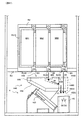
<前扉DUに設けられたその他の機構>
次に前扉DUに設けられたその他の機構の要部について図2の前扉DUを開いて回胴式遊技機Pの内部の構成を示した斜視図も参照しつつ説明する。前扉DUには、遊技の興趣性を高めるための機構として、予告演出や背景演出等の演出を表示するための演出表示装置S40、様々な点灯態様にて点灯し得る遊技効果ランプD26(不図示)、信号中継用の扉基板D、投入されたメダルの検出等を行なうメダルセレクタDS、サウンドを出力し得るスピーカS20、合成樹脂等によって形成された部材である、中パネル(中装飾パネル)、上パネルD130及び下パネルD140、等が設けられている。演出表示装置S40は、上パネルに形成された透視領域を介して演出等を表示する表示部が視認可能となるように前扉DUの裏面側上部に取り付けられている。また、装飾ランプユニットD150及びLEDランプユニットS10は、回胴式遊技機Pの遊技の進行に応じて発光する発光源を有しており、下パネルD140を挟んで右側及び左側の各々に装飾ランプユニットD150が設けられ、上パネルD130を挟んで右側及び左側の各々にLEDランプユニットS10が設けられている。また、前扉DUの背面におけるリール窓D160の下方には、扉基板Dが取り付けられており、この扉基板Dには、前述した停止ボタンD40や、スタートレバーD50、精算ボタンD60等の入力信号が入力され、入力された信号を直接或いは加工して後述する主制御基板Mに出力する中継基板の機能を有している。また、メダル投入口D170に対応し、前扉DUの背面における扉基板Dの付近には、詳細後述するメダルセレクタDSが設けられており、メダル投入口D170から投入されたメダルの検出並びに簡易的な真贋を行ない、適正なメダルを後述するホッパH40に案内し、不適正なメダルを後述するメダル受け皿D230に返却する機能を有している。更に、扉基板Dの下方の左右にスピーカS20が夫々1つずつ設けられている。中パネルは、操作卓の上側、上パネルD130の下側の部分であり、前述したリール窓を含むパネル部分である。また、前述した操作卓D190に取り付けられているサブ入力ボタンSB及び十字キーSB2とは、後述するメニュー画面における操作や副制御基板S側でのボタン連打演出(サブ入力ボタンSBを連打操作することによって、ボーナスに当選しているか否かに関する演出を実行する)やミニゲーム(例えば、「AT中状態」への突入の成否の演出)等の進行等に用いる部材である。なお、回胴式遊技機Pの前扉DUには、放出口D240から放出された遊技メダル(或いは単にメダルと呼ぶことがある)を受けるメダル受け皿D230、前扉DUの開閉状態を検出可能な扉スイッチD80が設けられている。また、前扉DUには鍵穴D260が設けられており、鍵穴D260の形状と整合するキー(ドアキー)を鍵穴D260に差し込む{加えて、所定の方向(例えば、時計回り)に捻る}ことで、前扉DUを開放し得るよう構成されている。更に、本実施形態においては、ドアキーを
鍵穴D260に差し込む{加えて、所定の方向(例えば、反時計回り)に捻る}ことで、エラー状態(ドア開放エラー等)を解除し得るよう構成されている。また、ベットボタンD220の内部にはベットボタンランプS50が設けられており、ベットボタンランプS50は、副制御基板Sにて制御されるLEDで構成されており、ベットボタンランプS50が点灯(又は点滅)することにより、ベットボタンD220の操作が有効であることを遊技者に知覚させることができる。また、停止ボタンD40の内部には停止ボタンランプS60が設けられており(左停止ボタンD41、中停止ボタンD42、右停止ボタンD43の3つの停止ボタンに夫々設けられている)、停止ボタンランプS60は、副制御基板Sにて制御されるLEDで構成されており、停止ボタンランプS60の点灯(又は点滅)の有無及び/又は点灯色により、停止ボタンD40の操作が有効であることを遊技者に知覚させることができる。尚、有効である停止ボタンD40に対応した点灯色にて点灯するのは有効である停止ボタンD40に対応した停止ボタンランプS60のみとなるよう構成されているため、例えば、左停止ボタンD41が無効、中停止ボタンD42が有効、右停止ボタンD43が有効である場合には、左停止ボタンD41に対応した停止ボタンランプS60が消灯、中停止ボタンD42に対応した停止ボタンランプS60が点灯、右停止ボタンD43に対応した停止ボタンランプS60が点灯のように、3つの停止ボタンランプS60の点灯態様が夫々相違し得るよう構成されている。また、停止ボタンランプS60の点灯色や点灯態様を相違させることにより(点灯・点滅のように相違させたり、低速点滅・高速点滅のように相違させてもよい)、押し順ナビが実行されるゲームにて、現在停止操作するべき停止ボタンを遊技者が判別し易くなるよう構成してもよく、例えば、すべてのリールが回転中であり、「左→中→右」の押し順が正解(最大の払出枚数)となる押し順ベルに当選している場合に、左停止ボタンに対応する停止ボタンランプを白色で点滅させ、中停止ボタンに対応する停止ボタンランプと右停止ボタンに対応する停止ボタンランプとを青色に点灯させ、その後、遊技者が左停止ボタンを操作して左リールを停止させた場合には、左停止ボタンに対応する停止ボタンランプを消灯させ、中停止ボタンに対応する停止ボタンランプを白色で点滅させ、右停止ボタンに対応する停止ボタンランプとを青色に点灯させるよう構成してもよい。
<Other mechanisms provided on the front door DU>
Next, main parts of other mechanisms provided in the front door DU will be described with reference to a perspective view showing the internal structure of the spinning-type gaming machine P by opening the front door DU in FIG. The front door DU includes, as a mechanism for enhancing the interest of the game, an effect display device S40 for displaying an effect such as a notice effect or a background effect, and a game effect lamp D26 (not shown) that can be turned on in various lighting modes. Illustrated), a door board D for signal relay, a medal selector DS for detecting inserted medals, etc., a speaker S20 capable of outputting sound, a middle panel (middle decorative panel) which is a member formed of synthetic resin or the like. , An upper panel D130, a lower panel D140, and the like. The effect display device S40 is attached to the upper portion on the back side of the front door DU so that a display unit for displaying effects and the like can be visually recognized through a see-through area formed on the upper panel. Further, the decorative lamp unit D150 and the LED lamp unit S10 have a light emitting source that emits light in accordance with the progress of the game of the spinning-type gaming machine P, and the decorative lamps are provided on the right and left sides of the lower panel D140, respectively. A unit D150 is provided, and an LED lamp unit S10 is provided on each of the right and left sides of the upper panel D130. A door substrate D is attached to the back of the front door DU below the reel window D160. The door substrate D has input signals such as the stop button D40, start lever D50, and settlement button D60 described above. And has a function of a relay board that directly or processes the input signal and outputs it to a main control board M described later. In addition, a medal selector DS, which will be described in detail later, is provided near the door substrate D on the back surface of the front door DU, corresponding to the medal slot D170. It has a function of performing proper authentication, guiding an appropriate medal to a hopper H40 described later, and returning an inappropriate medal to a medal tray D230 described later. Further, one speaker S20 is provided on each of the left and right sides below the door substrate D. The middle panel is the upper part of the console, the lower part of the upper panel D130, and is the panel part including the above-mentioned reel window. The sub-input button SB and the cross key SB2 attached to the console D190 described above are an operation on a menu screen, which will be described later, and a button-stroke effect on the sub-control board S (a continuous-stroke operation of the sub-input button SB). This is a member used for performing an effect relating to whether or not a bonus has been won), a mini-game (for example, an effect of whether entry into the “AT state” is successful or not), or the like. Note that the front door DU of the spinning-type gaming machine P can detect a medal tray D230 that receives game medals (or may be simply called medals) discharged from the discharge port D240 and an open / closed state of the front door DU. A door switch D80 is provided. Further, a keyhole D260 is provided in the front door DU, and a key (door key) matching the shape of the keyhole D260 is inserted into the keyhole D260 {in addition, by twisting in a predetermined direction (for example, clockwise)}, It is configured so that the front door DU can be opened. Further, in the present embodiment, the error state (door opening error or the like) can be released by inserting the door key into the keyhole D260 (in addition to twisting it in a predetermined direction (for example, counterclockwise)). I have. A bet button lamp S50 is provided inside the bet button D220. The bet button lamp S50 is configured by an LED controlled by the sub-control board S, and the bet button lamp S50 is turned on (or blinks). ), It is possible for the player to perceive that the operation of the bet button D220 is effective. Further, a stop button lamp S60 is provided inside the stop button D40 (the stop button lamp S60 is provided on each of the three stop buttons of the left stop button D41, the middle stop button D42, and the right stop button D43). Is configured by an LED controlled by the sub-control board S, and the player determines that the operation of the stop button D40 is effective by the presence / absence of lighting (or blinking) of the stop button lamp S60 and / or the lighting color. Can be perceived. It should be noted that since only the stop button lamp S60 corresponding to the valid stop button D40 is illuminated in the lighting color corresponding to the valid stop button D40, for example, the left stop button D41 is invalid. When the middle stop button D42 is valid and the right stop button D43 is valid, the stop button lamp S60 corresponding to the left stop button D41 is turned off, the stop button lamp S60 corresponding to the middle stop button D42 is lit, and the right stop. The stop button lamps S60 corresponding to the button D43 are illuminated, so that the three stop button lamps S60 can be differently illuminated. Further, by changing the lighting color and the lighting mode of the stop button lamp S60 (the lighting color and the lighting mode may be changed, or the stop button lamp S60 may be changed such as the low-speed flashing and the high-speed flashing), the pressing order navigation is executed. The game may be configured so that the player can easily determine the stop button to be currently stopped, for example, all reels are spinning, and the pressing order of “left → middle → right” is correct ( The stop button lamp corresponding to the left stop button blinks in white when the push order bell which has the maximum payout number) is won, and the stop button lamp corresponding to the middle stop button and the stop corresponding to the right stop button When the button lamp is lit in blue and the player operates the left stop button to stop the left reel, the stop button lamp corresponding to the left stop button is turned off and the middle stop button is turned off. Blink white stop button lamp may be configured so as to light the stop button lamp corresponding to the right stop button blue.
次に裏箱(キャビネット、基体とも称す)並びに、裏箱内に設置される各装置について説明する。裏箱の略中央には、リール窓D160を介してその一部が視認可能となるようにリールユニットが取付られている。リールユニットは、リールM50とリールM50の駆動源(ステッピングモータ等)とを備えている。また、リールM50は、左リールM51、中リールM52、右リールM53を備えている。ここで、夫々のリール部は合成樹脂等により形成され、リール部の外周上(リール帯MO上)には複数の図柄が描かれている。そして、スタートレバーD50及び停止ボタンD40における各停止ボタンの操作に基づき、夫々のリール部の回転動作及び停止動作を可能とするよう構成されている。また、図示しないが、左リールM51、中リールM52及び右リールM53の内部にはLED(以下、リールバックライトと呼ぶことがある)が設けられており、LEDが点灯した際にはリール部外周を透過した光によって、リール部外周が点灯したように視認できるよう構成されている。また、リールM50の上方には、各リール(左リールM51、中リールM52、右リールM53)を駆動するための後述する回胴基板Kが格納されている。 Next, a back box (also referred to as a cabinet or a base) and each device installed in the back box will be described. A reel unit is attached to substantially the center of the back box so that a part thereof can be visually recognized through a reel window D160. The reel unit includes a reel M50 and a driving source (such as a stepping motor) for the reel M50. Further, the reel M50 includes a left reel M51, a center reel M52, and a right reel M53. Here, each reel portion is formed of a synthetic resin or the like, and a plurality of symbols are drawn on the outer periphery of the reel portion (on the reel band MO). Then, based on the operation of each stop button of the start lever D50 and the stop button D40, the rotation operation and the stop operation of each reel unit are enabled. Although not shown, LEDs (hereinafter, sometimes referred to as reel backlights) are provided inside the left reel M51, the middle reel M52, and the right reel M53, and when the LEDs are turned on, the outer periphery of the reel unit is provided. Is configured to be visually recognized as if the outer periphery of the reel unit is lit by light transmitted through the reel unit. Above the reel M50, a later-described spinning board K for driving each of the reels (the left reel M51, the middle reel M52, and the right reel M53) is stored.
また、リールM50の上方には、遊技全体の制御を司る後述する主制御基板Mが格納され、リールM50の左方には、図1に示した演出表示装置S40、LEDランプユニットS10、スピーカS20等を用いて行われる各種演出の制御を司る後述する副制御基板Sが格納されている。なお、主制御基板Mには、後述する設定変更装置制御処理を実行するため(設定変更を行うため)に使用する設定キースイッチM20、設定値の変更やエラー解除等を実行し得る設定/リセットボタンM30が接続されている。図2において、設定キースイッチM20、設定/リセットボタンM30については何れも不図示としているが、主制御基板Mの基板上等の適宜位置に設けられていればよい(即ち、前扉DUを開かな
ければ人為的なアクセスが困難な位置に設けられていればよい)。
Above the reel M50, a main control board M for controlling the entire game, which will be described later, is stored. Stores a sub-control board S, which will be described later, which controls various effects performed by using the above-described method. The main control board M has a setting key switch M20 used to execute a setting change device control process (to change a setting), which will be described later, and a setting / reset capable of changing a set value and canceling an error. Button M30 is connected. In FIG. 2, the setting key switch M20 and the setting / reset button M30 are not shown, but may be provided at appropriate positions on the main control board M (for example, when the front door DU is opened). If not, it is sufficient if it is provided in a position where human access is difficult).
リールM50の下方には、投入された遊技メダルが集められるホッパH40や、遊技メダルを払い出すメダル払出装置Hが設けられており、回胴式遊技機P全体に電源を供給するための電源基板Eが格納されている。メダル払出装置Hから払い出された遊技メダルは、コインシュータD90を通って、放出口D240から払い出されるようになっている。また、電源基板E(電源供給ユニットEとも称することがある)の前面には、回胴式遊技機Pの電源を投入するための電源スイッチE10も設けられている。なお、メダル払出装置Hの詳細については後述する。 Below the reel M50, a hopper H40 for collecting inserted game medals and a medal payout device H for paying out game medals are provided, and a power supply board for supplying power to the entire spinning-type gaming machine P is provided. E is stored. The game medals paid out from the medal payout device H pass through the coin shooter D90 and are paid out from the outlet D240. In addition, a power switch E10 for turning on the power of the spinning-type gaming machine P is provided on a front surface of the power supply board E (also referred to as a power supply unit E). The details of the medal payout device H will be described later.
<メダルセレクタDS>
次に、メダルセレクタDSについて、図3を交えつつ詳細に説明する。図3は、回胴式遊技機P内部における、メダル投入口D170に投入された遊技メダルの経路(セレクタ)を示した斜視図である。メダルセレクタDSは、扉基板Dの付近にメダル投入口D170から投入された遊技メダルの通路となる投入受付センサD10sが設けられており、投入受付センサD10sの下方には、遊技メダルを放出口D240に導くためのコインシュータD90などが設けられている。投入受付センサD10sは、メダル投入口D170から投入された遊技メダルを主に寸法に基づいて選別し、規格寸法に適合した遊技メダルだけを受け入れる機能を有しており、この機能により適合しないと判断されたメダル(又は、その他の異物)は、ブロッカD100により放出口D240に払い戻されるよう構成されている。遊技者がスタートレバーD50を操作する前に(遊技メダルの投入が有効である状態にて)遊技メダルを投入すると、遊技メダルは投入受付センサD10sによって選別され、規格を満足しているものだけがホッパH40内に投入され、規格を満たしていないメダルは、コインシュータD90を通って、放出口D240に返却されるようになっている。これに対して、スタートレバーD50が操作された後に(遊技メダルの投入が有効でない状態にて)遊技メダルが投入された場合は、規格を満たしているか否かに拘らず、投入された遊技メダルはコインシュータD90を通って、放出口D240に返却される。また、投入受付センサD10sの内部(流路の奥)には、詳細後述するメダル投入に係るセンサが設けられており、寸法規格を満たして受け入れられた遊技メダルが通過すると、第1投入センサD20s及び第2投入センサD30sによって検出されて、その信号が後述する主制御基板Mに供給されるようになっている。
<Medal selector DS>
Next, the medal selector DS will be described in detail with reference to FIG. FIG. 3 is a perspective view showing a path (selector) of game medals inserted into the medal insertion slot D170 inside the spinning-type gaming machine P. The medal selector DS is provided with an insertion reception sensor D10s serving as a path of a game medal inserted from the medal insertion port D170 near the door substrate D, and a game medal discharge port D240 below the insertion reception sensor D10s. A coin shooter D90 and the like are provided for guiding the user. The insertion receiving sensor D10s has a function of selecting game medals inserted from the medal insertion slot D170 mainly based on dimensions and accepting only game medals that conform to standard dimensions, and determines that the game medals are not adapted by this function. The arranged medals (or other foreign substances) are configured to be repaid to the discharge port D240 by the blocker D100. If the player inserts a game medal before the player operates the start lever D50 (in a state where the insertion of the game medal is valid), the game medal is selected by the insertion reception sensor D10s, and only the game medal that satisfies the standard is selected. The medals which are thrown into the hopper H40 and do not satisfy the standard pass through the coin shooter D90 and are returned to the discharge port D240. On the other hand, when the game medal is inserted after the start lever D50 is operated (in a state where the insertion of the game medal is not valid), the game medal inserted regardless of whether or not the standard is satisfied. Is returned to the outlet D240 through the coin shooter D90. A medal insertion sensor, which will be described in detail later, is provided inside the insertion reception sensor D10s (at the back of the flow path). The signal is detected by the second input sensor D30s, and the signal is supplied to a main control board M described later.
次に、メダル投入に係るセンサについて詳述する。メダル投入口D170に投入された遊技メダルは、まず投入受付センサD10sを通過する。投入受付センサD10sは機械式のダブルセンサになっており、遊技メダルが通過することによって、2つの突起した機構が押下されることによりオンとなり遊技メダルが正常に通路を通過することができることとなる。また、このような構成により、遊技メダルではない異物(規格を満足していない異物であり、例えば、遊技メダルよりも径が小さいもの)が投入された場合には、2つの突起した機構が押下されない。このようなメダルは、起立した状態をメダルが維持できないため、通路を通過できず(メダルが倒れこむ)、前述したようにコインシュータD90を通って放出口D240に払い戻されることとなる。そのほかにも、投入受付センサD10sは、オンとなっている時間が所定時間以上連続した場合等にも、エラーであると判定し得る(その結果、ブロッカD100がオフとなり得る)よう構成されている。 Next, a sensor relating to medal insertion will be described in detail. The game medals inserted into the medal insertion slot D170 first pass through the insertion reception sensor D10s. The insertion receiving sensor D10s is a mechanical double sensor, and when a game medal passes, the two protruding mechanisms are pressed down to turn on and the game medal can normally pass through the passage. . Further, with such a configuration, when a foreign substance that is not a game medal (a foreign substance that does not satisfy the standard, for example, a diameter smaller than the game medal) is inserted, the two protruding mechanisms are pressed down. Not done. Such medals cannot pass through the aisle (the medals fall down) because the medals cannot be kept upright, and are paid back to the outlet D240 through the coin shooter D90 as described above. In addition, the input reception sensor D10s is configured to be able to determine that an error has occurred (as a result, the blocker D100 can be turned off) even when the on time has continued for a predetermined time or more. .
遊技メダルがブロッカD100を正常に通過した場合に、通過直後に第1投入センサD20s及び第2投入センサD30sを通過することとなる。この投入センサ(第1投入センサD20s及び第2投入センサD30s)は2つのセンサで構成されており(遊技メダルの規格上の直径よりも小さい間隔で隣接配置されており)、夫々のセンサのオン・オフ状況(第1投入センサD20s及び第2投入センサD30sのオン・オフの組み合わせの遷移していく順序、等)及びオン・オフとなっている時間を監視することにより様々なエ
ラーを検出可能に構成されている。
When the game medal normally passes through the blocker D100, the game medal passes through the first insertion sensor D20s and the second insertion sensor D30s immediately after passing. The input sensors (first input sensor D20s and second input sensor D30s) are composed of two sensors (arranged adjacent to each other at an interval smaller than the standard diameter of game medals), and each of the sensors is turned on. -Various errors can be detected by monitoring the OFF state (the order in which the combination of ON / OFF of the first input sensor D20s and the second input sensor D30s transitions, etc.) and the ON / OFF time. Is configured.
<メダル払出装置H>
次に、図4のメダル払出装置Hの正面図及び上面図を用いてメダル払出装置Hを詳細に説明する。メダル払出装置Hは、クレジット(遊技機内部に電子的に貯留されている遊技メダル)又はベットされているメダル(遊技を開始するために投入されたメダル)が存在する状態で、精算ボタンが操作された、又は、入賞により遊技メダルが払い出される場合に作動することとなる。作動する場合には、まず、ホッパモータH80が駆動することにより、ディスク回転軸H50aを中心にディスクH50が回転する。回転によりメダル払出装置H内の遊技メダルは放出付勢手段H70を変位させて遊技メダル出口H60から放出口D240に向かって流下していくこととなる。尚、払出センサ(第1払出センサH10s及び第2払出センサH20s)は2つのセンサで構成されており、夫々のセンサのオン・オフ状況(第1払出センサH10s及び第2払出センサH20sのオン・オフの組み合わせの遷移していく順序、等)及びオン・オフとなっている時間を監視することにより様々なエラーを検出可能に構成されている。より具体的には、例えば、遊技メダル出口H60を正常に通過する際には、放出付勢手段H70の変位により、第1払出センサH10s=オフ・第2払出センサH20s=オフの状態から、第1払出センサH10s=オフ・第2払出センサH20s=オフ→第1払出センサH10s=オン・第2払出センサH20s=オフ→第1払出センサH10s=オン・第2払出センサH20s=オン→第1払出センサH10s=オフ・第2払出センサH20s=オン→第1払出センサH10s=オフ・第2払出センサH20s=オフ、というセンサ状態遷移となるため、このセンサ状態遷移と反する動きを検出した場合には、エラーとするよう構成することを例示することができる。
<Medal payout device H>
Next, the medal payout device H will be described in detail with reference to a front view and a top view of the medal payout device H in FIG. The medal payout device H operates the settlement button when there is a credit (game medal electronically stored inside the gaming machine) or a betted medal (medal inserted for starting a game). It is activated when a game medal is paid out or a prize is paid out. In operation, first, the hopper motor H80 is driven to rotate the disk H50 about the disk rotation axis H50a. Due to the rotation, the game medals in the medal payout apparatus H are displaced by the discharge urging means H70 and flow down from the game medal exit H60 toward the discharge port D240. The payout sensors (the first payout sensor H10s and the second payout sensor H20s) are composed of two sensors, and the on / off state of each sensor (the ON / OFF state of the first payout sensor H10s and the second payout sensor H20s). Various errors can be detected by monitoring the transition order of the combination of OFF, etc.) and the ON / OFF time. More specifically, for example, when normally passing through the game medal exit H60, the displacement of the discharge urging means H70 causes the first payout sensor H10s to be turned off and the second payout sensor H20s to be turned off. 1 payout sensor H10s = off / second payout sensor H20s = off → first payout sensor H10s = on / second payout sensor H20s = off → first payout sensor H10s = on / second payout sensor H20s = on → first payout The sensor state transition is such that the sensor H10s = off, the second payout sensor H20s = on, the first payout sensor H10s = off, and the second payout sensor H20s = off. , An error can be exemplified.
次に、図5は、本実施形態における、回胴式遊技機の基本仕様一覧である。本実施形態に係る回胴式遊技機は、規定数(1ゲームにてベットできる遊技メダルの最大枚数)が3枚、左リールM51、中リールM52及び右リールM53のコマ数はいずれも20コマ、入賞判定される有効ラインは「左リールM51上段、中リールM52中段、右リールM53下段」の1ラインとなっている。尚、最大払出枚数は11枚、最小払出枚数は1枚(入賞役と払出枚数との対応付けは後述)である。また、優先入賞順(引き込み優先順)は、「再遊技役→小役(ベル、スイカ、等)→ボーナス」となっており、例えば、再遊技役とボーナスが同時に成立している場合には、再遊技役となる図柄組み合わせが停止表示し且つボーナスは入賞不能である。また、ベルとスイカが成立している場合には、どちらも引き込める位置(入賞する停止位置まで4コマ以内の位置)で停止ボタンを押した場合には払出枚数が多い小役を優先して引きこむよう構成されている。尚、同図に示した構成はあくまで一例であり、各リールのコマ数を変更(例えば、21コマに変更)したり、有効ラインの構成を変更(例えば、横3ライン、斜め2ラインの5ラインに変更、左リールM51下段、中リールM52中段、右リールM53上段の1ラインに変更)しても何ら問題ない。また、特に押し順によって遊技者にとって異なる利益が付与される押し順小役が当選したときの引き込み制御としては、予め定められた正解の押し順で操作された場合には払出し枚数の多い小役を優先して引き込むように制御(枚数優先制御)しており、正解の押し順とは異なる不正解の押し順で操作された場合には停止表示可能な(停止操作から4コマ以内の位置に配置されている)図柄のうち入賞可能性を高める(入賞可能な複数図柄組合せのうち入賞する可能性が最も多くなる)図柄を引き込む制御(個数優先制御)を行っている。 Next, FIG. 5 is a list of basic specifications of a spinning-type gaming machine in the present embodiment. The spinning-type gaming machine according to the present embodiment has a prescribed number (the maximum number of gaming medals that can be bet in one game) of three, and the left reel M51, the middle reel M52, and the right reel M53 each have twenty frames. The effective line for which the winning determination is made is one line of “upper left reel M51, middle middle reel M52, lower right reel M53”. The maximum payout number is 11 and the minimum payout number is 1 (the association between the winning combination and the payout number will be described later). In addition, the priority winning order (pull-in priority order) is “re-gaming role → small role (bell, watermelon, etc.) → bonus”. For example, if the re-gaming role and bonus are simultaneously established, , The symbol combination serving as the re-game combination is stopped and the bonus cannot be won. When the bell and the watermelon are established, when the stop button is pressed at a position where both of them can be retracted (a position within 4 frames to the stop position for winning), the small payout having a large number of payouts is given priority. It is configured to retract. Note that the configuration shown in the drawing is merely an example, and the number of frames on each reel is changed (for example, changed to 21 frames), and the configuration of the effective lines is changed (for example, 5 horizontal 3 lines and 2 diagonal lines). There is no problem if the line is changed to one line of the lower reel M51, the middle reel M52, and the right reel M53. In addition, as the pull-in control when a push order small combination that gives a different profit to the player according to the push order is won, the small combination with a large payout number when operated in a predetermined correct answer push order Is controlled so that it is pulled in with priority (number-of-sheets priority control), and if the operation is performed in the wrong push order different from the correct answer, the stop display is possible (the position within 4 frames from the stop operation is displayed). Among the symbols (arranged), a control (a number priority control) for increasing the winning probability (the number of winning combinations among a plurality of winning symbol combinations is the highest) is performed.
次に、図6は、本実施形態における、回胴式遊技機のリール配列一覧である。同図に示されるように、左リールM51、中リールM52及び右リールM53のコマ数はいずれも20コマ(0番〜19番)であり、図柄は「黒セブン」、「白セブン」、「羊」、「ブランク」、「ベル」、「リプレイA」、「リプレイB」、「スイカA」、「スイカB」、「
チェリー」の10種類となっている。ここで、「ブランク」は、その他の図柄と同様に当選役を構成する図柄組み合わせに含まれる図柄であり、当選役を構成しない図柄という意味ではなく、「ブランク」を含む当選役を構成する図柄組み合わせとしては、例えば、「スイカB・リプレイA・ブランク」で再遊技02となっている。尚、同図に示した構成はあくまで一例であり、図柄の種類を増減・変更しても何ら問題ない。
Next, FIG. 6 is a list of reel arrangements of the spinning-type gaming machine in the present embodiment. As shown in the figure, the number of frames of the left reel M51, the middle reel M52 and the right reel M53 is 20 (0 to 19), and the symbols are "black seven", "white seven", and "white seven". Sheep "," blank "," bell "," replay A "," replay B "," watermelon A "," watermelon B ","
Cherry ". Here, “blank” is a symbol included in the symbol combination that constitutes the winning combination like other symbols, and does not mean a symbol that does not constitute the winning combination, but a symbol that constitutes the winning combination that includes “blank”. As a combination, for example, “watermelon B / replay A / blank” is replay 02. It should be noted that the configuration shown in the figure is merely an example, and there is no problem even if the types of symbols are increased or decreased.
次に、図7〜図9は、本実施形態における図柄組み合わせ一覧1〜3である。本実施形態においては、夫々の条件装置に対して複数の図柄組み合わせが存在しており、後述するように、左リールM51、中リールM52及び右リールM53の停止順番や停止位置に応じて、いずれか一の図柄組み合わせが有効ライン(前述した1ライン)上に停止表示されるよう構成されている。尚、有効ライン上に同一種類の図柄が揃っていない場合にも遊技者から見ると有効ライン以外のライン上にて一列に同一の図柄が揃いやすく構成されている(スイカの場合には中段に横一直線に揃う等、リール上のいずれかに一直線にスイカ図柄が3つ揃うよう構成されている)。また、本実施形態においては、第1種BB役(いわゆる第1種特別役物に係る役物連続作動装置であるが、以下、単にBB役と呼ぶことがある)となる図柄組み合わせして、1種BB‐A(RB−Aを連続作動させ、264枚を超える払出で終了)となる「羊・羊・羊」と、1種BB‐B(RB−Bを連続作動させ、132枚を超える払出で終了)となる「黒セブン・黒セブン・黒セブン」と、1種BB‐C(RB−Bを連続作動させ、132枚を超える払出で終了)となる「白セブン・白セブン・白セブン」との3つの図柄組み合わせを有している。尚、本実施形態においては、第1種BB役が入賞し、BBが実行された(役物が作動した)場合には、当該BB実行中においては、BB中のすべてのゲームにおいて、1つの抽選テーブルを参照して、役物以外の当選役(小役、再遊技役)を抽選するよう構成されている(1回のBBの実行中において役抽選の際に参照するテーブルを切り替えない方式であり、以下、オールJACINタイプと呼ぶことがある)。尚、第1種BB役の形式に関しては、これには限定されず、1回のBBの実行中において役抽選の際に参照するテーブルを切り替え得るよう構成してもよい。また、RT状態が「RT1」である場合に14番〜16番に対応する再遊技04となる図柄組み合わせが停止表示されると、RT0に移行するよう構成されている(RT状態の詳細については後述する)。尚、「RT1」よりも「RT0」の方が遊技者に不利なRT状態であるため、「RT1」から「RT0」に移行することを転落すると称することがある。また、17番に対応する再遊技05となる図柄組み合わせが停止表示されると、左リールM51、中リールM52及び右リールM53の下段に「黒セブン」が停止表示され得ることとなり、18番に対応する再遊技05となる図柄組み合わせが停止表示されると、左リールM51、中リールM52及び右リールM53の下段に「白セブン」が停止表示され得ることとなる(詳細は後述することとする)。また、後述する「入賞‐A1」〜「入賞‐A6」の条件装置である押し順ベルが当選した場合には、遊技者にとって最も有利な押し順にてリールを停止させると、21番〜27番に対応する「入賞01」〜「入賞03」となる図柄組み合わせが停止表示され、11枚の遊技メダルが払い出される一方、遊技者にとって最も有利な押し順とは異なる押し順にてリールを停止させると、39番〜56番に対応する「入賞08」〜「入賞11」となる図柄組み合わせが停止表示され、1枚の遊技メダルが払い出されることとなる。尚、同図における「‐」はいずれの図柄が停止表示されてもよい旨を示しており、例えば、23番に対応する「ベル・‐・ベル」は左リールM51及び右リールM53の有効ライン上にベルが停止表示されれば中リールM52の有効ライン上にはどの図柄が停止表示されても11枚の遊技メダルが獲得できる。
7 to 9 are symbol combination lists 1 to 3 in the present embodiment. In the present embodiment, there are a plurality of symbol combinations for each condition device, and as described later, depending on the stop order and stop position of the left reel M51, the middle reel M52, and the right reel M53, as described later. The one symbol combination is configured to be stopped and displayed on the activated line (one line described above). In addition, even if the same type of symbols are not arranged on the activated line, the same symbols are easily arranged in a line on a line other than the activated line from the viewpoint of a player (in the case of a watermelon, the middle stage is arranged). For example, three watermelon designs are arranged in a straight line on any of the reels, such as being aligned horizontally.) Further, in the present embodiment, a symbol combination of a first type BB combination (a so-called
次に、図10は、本実施形態における条件装置一覧である。尚、同図においては、条件装置番号を当選番号と称しており、以降においても条件装置番号を当選番号と称することがある。本実施形態においては、再遊技役は再遊技‐A〜再遊技‐D3(当選番号1〜6)まで設けられており、左リールM51、中リールM52及び右リールM53の停止順番や停止位置に応じて、停止表示する再遊技役が相違し得るよう構成されている。ここで、
本実施形態においては、最も右の列である「条件装置」の項目に図示されているように、左リールM51、中リールM52及び右リールM53の停止順番や停止位置に応じて複数種類の条件装置が停止表示され得るよう構成されており、当該複数種類の条件装置のうち同一の当選番号となる条件装置を纏めて、右から3番目の列である「条件装置(名称)」の項目にて図示している。具体的には、例えば、当選番号1に対応する条件装置である「再遊技‐A」においては、左リールM51、中リールM52及び右リールM53の停止順番や停止位置に応じて、「再遊技01」、「再遊技02」、「再遊技03」の3種類の条件装置が停止表示され得るよう構成されている。尚、「条件装置(名称)」を単に条件装置と称することがある。また、「再遊技01」等の再遊技に関する条件装置を再遊技役と称することがあり、「入賞01」等の入賞することで遊技メダルが払い出される条件装置を小役と称することがあり、「1種BB‐A」等の停止表示されることによりBBが開始することとなる条件装置をBB役と称することがある。また、当選番号21〜23及び25〜27に当選した場合には、BB役と小役とが重複して当選することとなり、そのような場合には、当選した小役に対応する図柄が停止表示し得る位置にて左停止ボタンD41、中停止ボタンD42及び右停止ボタンD43を操作するとBB役に対応する図柄が停止表示せずに小役に対応する図柄が停止表示する一方、小役に対応する図柄が停止表示しない(引き込めない)位置にて左停止ボタンD41、中停止ボタンD42及び右停止ボタンD43を操作すると小役に対応する図柄が停止表示せずにBB役に対応する図柄が停止表示するよう構成されている。具体的には、例えば、当選番号21の条件装置である「1種BB‐B+入賞‐C」に当選した場合には、「入賞12」又は「入賞13」であるチェリーと、「1種BB‐B」である黒セブンとのいずれかが停止表示し得ることとなる。より具体的には、左リールM51→中リールM52→右リールM53の順番にリールを停止させる場合において、(1)第1停止にて左リールM51の上段に図柄番号0〜4番(図6のリール配列を参照)が位置している操作タイミングにて左停止ボタンD41を操作した場合には、左リールM51の上段に「入賞12」に対応する図柄番号4番が停止し、中リールM52及び右リールM53の停止位置に拘らず、「入賞12」が停止表示される。(2)第1停止にて左リールM51の上段に図柄番号5〜12番が位置している操作タイミングにて左停止ボタンD41を操作した場合には、左リールM51の上段に「入賞13」に対応する図柄番号6番、11番、又は16番が停止し、中リールM52及び右リールM53の停止位置に拘らず、「入賞13」が停止表示される。(3‐1)第1停止にて左リールM51の上段に図柄番号13〜19番が位置している操作タイミングにて左停止ボタンD41を操作した場合には、左リールM51の上段に「1種BB‐B」に対応する図柄番号17番又は19番が停止する。(3‐2)第2停止にて中リールM52の中段に図柄番号14〜18番が位置している操作タイミングにて中停止ボタンD42を操作した場合には、中リールM52の中段に「1種BB‐B」に対応する図柄番号18番が停止し、その後、第3停止にて右リールM53の下段に図柄番号13〜17番が位置している操作タイミングにて右停止ボタンD43を操作した場合には、右リールM53の下段に「1種BB‐B」に対応する図柄番号17番が停止し、BB役が停止表示されることとなる。(3‐3)第2停止にて中リールM52の中段に図柄番号19〜13番が位置している操作タイミングにて中停止ボタンD42を操作した場合には、中リールM52の中段に「1種BB‐B」に対応する図柄番号18番が停止できず、いずれの条件装置も停止表示されないこととなる。
Next, FIG. 10 is a list of condition devices in the present embodiment. In the figure, the condition device number is referred to as a winning number, and hereinafter, the condition device number may be referred to as a winning number. In the present embodiment, the re-gaming combination is provided from re-gaming-A to re-gaming-D3 (winning
In the present embodiment, as shown in the item of “condition device” in the rightmost column, a plurality of types of conditions are determined according to the stop order and the stop positions of the left reel M51, the middle reel M52, and the right reel M53. The apparatus is configured so that the apparatus can be stopped and displayed, and among the plurality of types of condition apparatuses, the condition apparatuses having the same winning number are put together, and the “condition apparatus (name)” item in the third column from the right is collected. Is shown. Specifically, for example, in “re-game-A” which is a condition device corresponding to the winning
次に、「役割」の項目には、「条件装置(名称)」がどのような役割となっているかを図示しており、当選番号1に対応する「通常リプレイ」は、停止ボタンの押し順に拘らず、RT状態が移行しない再遊技役が停止表示される再遊技に係る条件装置であり、当選番号2に対応する「逆押し白7揃いリプレイ」は、停止ボタンの押し順に拘らず、RT状態が移行しない再遊技役が停止表示される再遊技に係る条件装置であるが、逆押し(右リールM53→中リールM52→左リールM51の順にリールを停止させること)にて、右リールM53の図柄番号18〜2番の範囲、中リールM52の図柄番号9〜13番の範囲、
左リールM51の図柄番号5〜10番の範囲が各リールの下段に位置している操作タイミングにて停止ボタンを操作することにより、右リールM53、中リールM52及び左リールM51の下段に「白セブン」が停止表示され、遊技者から見ると白セブンが下段に揃っているように見えるよう構成されている。尚、再遊技‐Bに当選し、AT上乗せ抽選に当選したゲームにおいて、逆押しで「白セブン」を狙うよう指示する演出(詳細は後述する)を実行することにより、AT上乗せ抽選に当選した旨を遊技者に報知し得るよう構成されている。当選番号3に対応する「順押し黒7揃いリプレイ」は、停止ボタンの押し順に拘らず、RT状態が移行しない再遊技役が停止表示される再遊技に係る条件装置であるが、順押し(左リールM51→中リールM52→右リールM53の順にリールを停止させること)にて、左リールM51の図柄番号13〜19番の範囲、中リールM52の図柄番号14〜18番の範囲、右リールM53の図柄番号13〜17番の範囲が各リールの下段に位置している操作タイミングにて停止ボタンを操作することにより、左リールM51、中リールM52及び右リールM53の下段に「黒セブン」が停止表示され、遊技者から見ると黒セブンが下段に揃っているように見えるよう構成されている。尚、再遊技‐Cに当選し、AT上乗せ抽選に当選したゲームにおいて、順押しで「黒セブン」を狙うよう指示する演出(詳細は後述する)を実行することにより、AT上乗せ抽選に当選した旨を遊技者に報知し得るよう構成されている。
Next, the “role” item shows what role the “condition device (name)” plays, and “normal replay” corresponding to the winning
By operating the stop button at the operation timing in which the range of the
また、当選番号4に対応する「RT維持RP1**(3択)」は第1停止リールを左リールM51と中リールM52と右リールM53とのいずれにするか(いずれの停止ボタンを操作するか)によって、停止表示される再遊技役が相違し得る条件装置であり、第1停止リールを左リールM51とした場合には、RT状態が移行しない再遊技01、再遊技02又は再遊技03が停止表示され、第1停止リールを中リールM52又は右リールM53とした場合には、RT状態が「RT1」から「RT0」に移行し得る再遊技04が停止表示される。また、当選番号5に対応する「RT維持RP*1*(3択)」は第1停止リールを左リールM51と中リールM52と右リールM53とのいずれにするか(いずれの停止ボタンを操作するか)によって、停止表示される再遊技役が相違し得る条件装置であり、第1停止リールを中リールM52とした場合には、RT状態が移行しない再遊技03が停止表示され、第1停止リールを左リールM51又は右リールM53とした場合には、RT状態が「RT1」から「RT0」に移行し得る再遊技04が停止表示される。また、当選番号6に対応する「RT維持RP**1(3択)」は第1停止リールを左リールM51と中リールM52と右リールM53とのいずれにするか(いずれの停止ボタンを操作するか)によって、停止表示される再遊技役が相違し得る条件装置であり、第1停止リールを右リールM53とした場合には、RT状態が移行しない再遊技01又は再遊技03が停止表示され、第1停止リールを左リールM51又は中リールM52とした場合には、RT状態が「RT1」から「RT0」に移行し得る再遊技04が停止表示される。
"RT maintenance RP1 ** (three options)" corresponding to the winning
また、当選番号7〜12に対応する、「押し順ベル123」〜「押し順ベル321」は、リール停止順を6択のいずれとするかによって入賞する小役が相違し得る条件装置であり、例えば、「左リールM51:1、中リールM52:2、右リールM53:3」となっており「123」の場合「左リールM51→中リールM52→右リールM53」の押し順で停止させるという意味であり、例えば、「入賞A‐1」(当選番号7)の場合には、「123」=「左→中→右」の順に停止させる(押し順に正解する)と最大獲得枚数である11枚の遊技メダルが獲得できる「入賞01」となる図柄組み合わせが停止表示することとなる。尚、「押し順ベル123」の「123」等はその当選番号における最大獲得枚数を獲得可能な押し順(リール停止順)を示している。尚、最大獲得枚数を獲得可能な押し順以外の押し順にてリールを停止させた場合には、即ち、押し順に正解できないと1枚の払出となるよう構成されており、このように構成することで、「AT中状態」等のATに関する状態にて再遊技役の押し順やベルの押し順をナビ(押し順表示装置D270にて最高利益となる押し順を表示)し、「通常遊技状態」等のATに関する状態には押し順をナ
ビしないという遊技者の利益率が異なる複数の遊技状態を創出することができる。尚、ATに関する状態については後述する。
The "push order bell 123" to "push order bell 321" corresponding to the winning
また、当選番号13に対応する、「共通ベル」は、入賞04〜入賞07のいずれが停止しても最大獲得枚数である11枚の遊技メダルが獲得できる、即ち、押し順に拘らず最大利益が獲得できる条件装置であり、押し順不問ベルと称することがある。また、当選番号15に対応する、「スイカA」は、平行ラインにスイカ(スイカAとスイカBのいずれか)が3つ揃いし易いよう構成されており、例えば、図9における60番の入賞14は各リール中段にスイカAが3つ揃いすることとなる。また、当選番号16に対応する、「スイカB」は、斜めラインにスイカ(スイカAとスイカBのいずれか)が3つ揃いし易いよう構成されており、例えば、図9における66番の入賞16は左リールM51上段にスイカB、中リールM52中段にスイカB、右リールM53下段にスイカAのように、斜め右下がりにスイカが3つ揃いすることとなる。また、当選番号17に対応する、「BB中弱レア小役(斜めベル揃い)」は、有効ライン上にベルが3つ揃いし得る条件装置であり、詳細は後述するが、BB中に当選することによってAT上乗せ抽選が実行される条件装置である。また、当選番号18に対応する、「BB中強レア小役(V字ベル揃い)」は、左リールM51上段、中リールM52中段、右リールM53上段にベルが停止表示され得る条件装置であり、詳細は後述するが、BB中に当選することによってAT上乗せ抽選が実行される条件装置である。
In addition, the “common bell” corresponding to the winning
次に、「ボーナス当選情報」の項目には、0〜3までの数値が当選番号毎に振り分けられている。本実施形態においては、ボーナス(BB役)が含まれない当選番号はボーナス当選情報を0とし、ボーナス(BB役)が含まれる当選番号として、1種BB‐Aが含まれる当選番号(19)のボーナス当選情報を1、1種BB‐Bが含まれる当選番号(20〜23)のボーナス当選情報を2、1種BB‐Cが含まれる当選番号(24〜27)のボーナス当選情報を3としている。ボーナス当選情報を主制御基板Mが記憶することによっていずれのBB成立の有無やいずれのBB役に当選したかに係る情報を記憶することができる。尚、ボーナス当選情報の詳細については後述する。 Next, in the item of "bonus winning information", numerical values from 0 to 3 are sorted for each winning number. In the present embodiment, a winning number that does not include the bonus (BB role) has the bonus winning information set to 0, and a winning number that includes one type of BB-A as the winning number that includes the bonus (BB role) (19) The bonus winning information of the winning number (20 to 23) containing one kind of BB-B, and the bonus winning information of the winning number (24 to 27) containing one kind of BB-C. And By storing the bonus winning information in the main control board M, it is possible to store information on which BB has been established and which BB combination has been won. The details of the bonus winning information will be described later.
次に、「入賞・再遊技当選情報」の項目には、0〜18までの数値が当選番号毎に振り分けられている。本実施形態においては、再遊技役と小役とが含まれない当選番号(ハズレに対応する当選番号0とボーナスに対応する当選番号19・20・24)は入賞・再遊技当選情報を0とし、再遊技役又は小役が含まれる当選番号に対して1〜18入賞・再遊技当選情報を条件装置毎に振り分けている。入賞・再遊技当選情報を主制御基板Mが記憶することによっていずれの再遊技役又は小役に当選したかに係る情報を記憶することができる。尚、入賞・再遊技当選情報の詳細については後述する。
Next, in the item of "winning / replay winning information", numerical values from 0 to 18 are allocated for each winning number. In the present embodiment, the winning numbers (winning
次に、「演出グループ番号」の項目には、0〜11までの数値が当選番号毎に振り分けられている。演出グループ番号を主制御基板M側から副制御基板S側に送信することによって、副制御基板S側が実行する演出を決定することができるよう構成されている。尚、演出グループ番号の詳細については後述する。 Next, numerical values from 0 to 11 are sorted for each winning number in the item of “effect group number”. By transmitting the effect group number from the main control board M side to the sub control board S side, the effect to be executed by the sub control board S side can be determined. The details of the effect group number will be described later.
次に、「出玉グループ番号」の項目には、0〜13までの数値が当選番号毎に振り分けられている。出玉グループ番号を主制御基板Mが記憶し、当該記憶した出玉グループ番号をATに関する抽選(例えば、AT抽選、AT上乗せ抽選)を実行する際に使用することにより、ATに関する抽選処理を実行するためのプログラム、データ容量を削減することができる。尚、出玉グループ番号が0となる条件装置が当選してもAT抽選及びAT上乗せ抽選は実行されない。一方、出玉グループ番号が0でない条件装置が当選した場合には、AT抽選又はAT上乗せ抽選が実行され得ることとなる。尚、出玉グループ番号の詳細については後述する。また、出玉グループ番号が0となる条件装置が当選した場合にも、
AT抽選又はAT上乗せ抽選が実行され得るよう構成してもよく、そのように構成した場合には、出玉グループ番号が0となる条件装置が当選してAT抽選又はAT上乗せ抽選が実行された場合には、当該抽選結果がかならずハズレ(非当選)となるよう構成することが好適である。
Next, in the item of the payout group number, numerical values from 0 to 13 are assigned for each winning number. The main control board M stores the payout group number, and executes the lottery process related to the AT by using the stored payout group number when performing the lottery related to the AT (for example, the AT lottery, the AT addition lottery). Programs and data capacity required for the execution. Note that the AT lottery and the AT addition lottery are not executed even if the condition device in which the payout group number becomes 0 is won. On the other hand, when the condition device with the payout group number other than 0 is won, the AT lottery or the AT addition lottery can be executed. The details of the payout group number will be described later. Also, when the condition device in which the payout group number becomes 0 is won,
The AT lottery or the AT addition lottery may be configured to be executed. In such a case, the condition device with the payout group number of 0 is won and the AT lottery or the AT addition lottery is executed. In such a case, it is preferable that the lottery result is always lost (non-winning).
次に、図11は、本実施形態における小役、再遊技役に関する当選番号(条件装置番号、当選役とも称す)及びボーナス(BB、BB役とも称す)が役抽選手段により決定される抽選確率(当選率とも称する)を示す一覧である。同図においては、当選番号の当選率を図示している。 Next, FIG. 11 shows a lottery probability in which a winning number (also referred to as a condition device number, also referred to as a winning role) and a bonus (also referred to as a BB role, BB) for a small role, a replaying role in the present embodiment are determined by the role lottery means. It is a list showing (winning rate). In the figure, the winning rate of the winning number is shown.
まず、BB未作動時である「RT0」、「RT1」及び「RT2」における抽選確率について詳述する。本実施形態においては、RT状態によって当選役(特に、再遊技役)の出現率(抽選確率)が相違し得るよう構成されており、「再遊技役」(すべての再遊技役を合計した出現率)は「RT1」の場合においてその他のRT状態よりも出現率が高くなっている。また、当選番号4〜6にて停止表示し得る「再遊技04」(いわゆる転落再遊技役であり、「RT1」であり且つボーナスが当選していない状況下において当該再遊技役に対応する図柄組合せが停止表示されると、以降「RT0」に移行することとなる)は「RT1」にて主に当選し、「RT0」においてはほぼ出現しないようになっている。尚、「RT2」においては、当選番号4〜6にて停止表示し得る「再遊技04」が出現し得ることとなるが、「再遊技04」が停止表示されてもRT状態は移行しない。尚、「RT1」において「再遊技04」が停止表示された場合には、「RT0」に移行した、即ち、RT状態が転落した旨を報知する演出である転落演出(例えば、演出表示装置S40に「残念」と表示)を実行し、「RT0」において「再遊技04」が停止表示された場合には、転落演出を実行しないよう構成してもよい。そのように構成することにより、「再遊技04」が停止表示されたにも拘らず、転落演出が実行されなかったことにより、BBに当選していることを認識することができ、遊技の興趣性を高めることができる。尚、そのように構成した場合には、「再遊技04」が停止表示されたことにより出力される効果音と「再遊技04」以外の再遊技役(例えば、RT状態が移行しない「再遊技01」)が停止表示されたことにより出力される効果音とが相違するよう構成してもよく、そのように構成することにより、「再遊技04」が停止表示されたことを遊技者が認識し易く構成することができる。また、押し順ナビが発生しないATに関する状態(例えば、「通常遊技状態」であり、非AT遊技状態と称することがある)である場合と押し順ナビが発生し得るATに関する状態(例えば、「AT中状態」であり、AT遊技状態と称することがある)である場合との両方の場合において「RT1」に滞在することがある。このとき、「RT1」から「RT0」へ移行(転落)する可能性がある当選番号が当選したとき、非AT遊技状態のときにはRT状態が転落する可能性があることを示す特殊な効果音をスタートレバーD50の操作に基づいて出力しないように構成されていても良い。これにより、非AT遊技状態においては「RT0」に転落する可能性があることを遊技者に悟らせることなく、遊技状態を移行させることが可能となる。一方、AT遊技状態のときにはRT状態が転落する可能性があることを示す特殊な効果音をスタートレバーの操作に基づいて出力する(且つ、RT状態が転落しない再遊技役が停止表示される押し順ナビを報知する)ように構成されていても良い。これにより、RT状態が転落しないよう遊技者は気を付けて、特殊な効果音が報知された以降の停止ボタンD40の操作を行なうことが可能となる。また、当選番号2又は3にて停止表示し得る「再遊技05」(AT状態にて停止表示された場合にAT上乗せ抽選に当選した旨を報知し得る再遊技役)は主に「RT1」で出現し、その他のRT状態ではほぼ出現しないようになっている。尚、これら再遊技役となる図柄組み合わせの停止表示に伴うRT状態に関する状態の遷移については後述する。また、後述するように、本実施形態においては、遊技者に最も有利となるリール停止順を報知する押し順ナビを押し順表示装置D270及び演出表示装置S40にて実行し得るよう構成されている。尚、当該抽選確率を適宜変更しても何ら問題ない。また、本実施形態において
は、ボーナスは小役と重複し得るよう構成されており、スイカA、スイカB、チェリーの一部と重複している。具体的には、当選番号21〜23及び当選番号25〜27がボーナスと小役とが重複している条件装置となっている。
First, the lottery probabilities in “RT0”, “RT1”, and “RT2” when the BB is not operating will be described in detail. In the present embodiment, the appearance rate (lottery probability) of the winning combination (especially, the replaying role) may be different depending on the RT state, and the “replaying role” (appearance of all replaying roles in total) Rate) is higher in the case of “RT1” than in the other RT states. In addition, "re-game 04" which can be stopped and displayed at the winning
また、「RT2」である状況においては、BBに当選しており、且つ、BBが未作動である状況であるため、当選番号20及び24のBB役(小役とは重複していない単独のBB役であり、単独BB役、単独BBと称することがある)に当選した場合には、BB役の新たな当選は無効となり、小役の当選のみが有効となる。具体的には、例えば、「RT2」であり、且つ、1種BB‐Aに当選している(持ち越している)状況下、当選番号24の「1種BB‐C」に当選した場合には、当該当選番号24に係る1種BB‐Cは無効となる。即ち、当選番号0の「ハズレ」に当選した場合と同様の状況となる。尚、持ち越している1種BB‐Aは当選している状態が継続される。また、「RT2」である状況においては、BBに当選しており、且つ、BBが未作動である状況であるため、当選番号21〜23及び当選番号25〜27の小役とBB役とが重複している条件装置に当選した場合には、BB役の新たな当選は無効となり、小役の当選のみが有効となる。具体的には、例えば、「RT2」であり、且つ、1種BB‐Aに当選している(持ち越している)状況下、当選番号21の「1種BB‐B+入賞‐C」に当選した場合には、当該当選番号21に係る1種BB‐Bは無効となり、入賞‐Cのみが有効となる。即ち、当選番号14の「入賞‐C」に当選した場合と同様の状況となる。尚、持ち越している1種BB‐Aは当選している状態が継続される。尚、ボーナスとの重複は小役に限られるものでなく、再遊技役の一部とで重複していても良い。例えば、当選番号4〜6の再遊技役の一部でボーナス役と重複しても良い。このように、ボーナスがRT移行リプレイ(RT状態が移行し得る再遊技役)を含む条件装置とも重複するようにすることで、RT移行リプレイを含む条件装置が当選したときにもボーナスが当選する可能性があり、RT移行リプレイが停止表示されても、ボーナスの否定をしないこととなるため、遊技者に期待を持たせることが可能となる。なお、このように構成した場合には、RT移行リプレイが停止表示されてもRT状態は移行しないように制御する。これにより、遊技者はRT状態が移行(リプレイ確率が相対的に低いRT状態に移行)しているはずであるのにリプレイ確率が低確率になっていない(頻繁にリプレイに当選する)こと等から、ボーナスに当選している可能性が高いかもしれないといった遊技に関する興趣を高めることが可能となる。
In addition, in the situation of “RT2”, since the BB has been won and the BB has not been activated, the BB role of the winning
次に、BB作動時である「1種BB‐A,B,C」における抽選確率について詳述する。本実施形態においては、BB作動中においては、当選番号13の「共通ベル」と当選番号17の「BB中弱レア小役(斜めベル揃い)」と当選番号18の「BB中強レア小役(V字ベル揃い)」との3つの小役が当選し得るよう構成されており、「AT中状態」にて当選したBBの作動中において「BB中弱レア小役(斜めベル揃い)」又は「BB中強レア小役(V字ベル揃い)」に当選した場合にはAT上乗せ抽選が実行されるよう構成されている(詳細は後述することとする)。
Next, the lottery probability in “one type BB-A, B, C” at the time of BB operation will be described in detail. In the present embodiment, during the BB operation, the winning
また、同図上段においては、設定値が1である場合の小役出現率を例示しており、共通ベル(当選番号13)においては、RT状態に拘らず出現率が一律となっているが、同図下段に示すように、共通ベルの出現率は設定値(本例では、6段階)によって相違するよう構成されている。具体的には、設定1における置数が3204、設定2における置数が3404、設定3における置数が3604、設定4における置数が3904、設定5における置数が4204、設定6における置数が4504、となっており、設定値が高くなる程出現率が高くなるよう構成されている。このように構成することにより、例えば、遊技者が共通ベルの出現回数(当選回数)を計測しながら遊技を進行した場合、共通ベルに頻繁に当選することにより、遊技している遊技機に係る設定値が相対的に高い設定値であることに期待を抱きながら遊技を進行することができる。また、設定値が高くなるほど1遊技当たりにおける期待値が高くなり、設定値が高くなるほど出玉率が高くなるように構成
されている。なお、共通ベルの出現率は設定値によって相違するよう構成されているが、当該共通ベルの当選によっては、後述するAT抽選、AT上乗せ抽選、及び、高確率状態移行抽選は実行されないので、ATに関する状態の移行抽選(ATに関する抽選とも称する。)には影響を及ぼさないよう構成されている。
In the upper part of the figure, the small combination appearance rate when the set value is 1 is illustrated. In the common bell (winning number 13), the appearance rate is uniform regardless of the RT state. As shown in the lower part of the figure, the appearance rate of the common bell is configured to be different depending on the set value (six levels in this example). Specifically, the setting number in setting 1 is 3204, the setting number in setting 2 is 3404, the setting number in setting 3 is 3604, the setting number in setting 4 is 3904, the setting number in setting 5 is 4204, and the setting number in setting 6 is Is 4504, and the appearance rate increases as the set value increases. With such a configuration, for example, when the player proceeds with the game while measuring the number of appearances of the common bell (the number of wins), the player frequently wins the common bell, thereby providing a game machine that is playing. The game can be advanced while expecting that the set value is a relatively high set value. Also, the higher the set value, the higher the expected value per game, and the higher the set value, the higher the payout rate. The appearance rate of the common bell is configured to be different depending on the set value. However, depending on the winning of the common bell, AT lottery, AT addition lottery, and high-probability state transition lottery described later are not executed. It is configured not to affect the transition lottery of the state related to (also referred to as the lottery relating to the AT).
また、同図中段は、押し順ナビあり時における期待値一覧である。同図においては、「AT中状態」等の押し順表示装置D270及び演出表示装置S40にて押し順ナビが実行され得る状態において押し順ナビが実行された場合に、当該ナビに従ってリールを停止させた場合の1遊技あたりの平均払出数(入賞した小役によって払い出される平均のメダル
の枚数であり、1ゲームで得られる遊技媒体の期待数とも称する)と、1遊技あたりのメ
ダル増減期待値(3枚ベットにて遊技した場合のメダル投入枚数に対するメダル払出枚数
の比率であり、1より大きい場合には期待値がプラスとなりメダルが増加していくこととなる一方、1より小さい場合には期待値がマイナスとなりメダルが減少していくこととなる)とを図示している。尚、1遊技あたりの平均払出数は、「再遊技役の置数の総和(当
選番号1〜6についての置数の総和)×再遊技役における払出枚数(3枚)+小役(11枚役)の置数(小役出現率)の総和(当選番号7〜16についての置数の総和)×小役(11枚役)における払出枚数(11枚)/すべての置数の総和(65536)」のようにして算出することができる。また、1遊技あたりのメダル増減期待値は、「1遊技あたりの平均払出数/1遊技あたりのメダル投入枚数(3枚)」のようにして算出することができる。尚、1ゲームあたりのメダル投入数(1ゲームを行う際の遊技媒体の投入数)は3枚となっており、1遊技あたりの平均払出数が3より大きい場合に1遊技あたりのメダル増減期待値が1より大きくなるよう構成されている。同図に示されるように、本実施形態においては、「RT1」が1遊技あたりのメダル増減期待値が相対的に最も大きくなっている。尚、同図における数値はボーナスによるメダルの増減は考慮していない。即ち、押し順ナビが発生する状況において遊技を進行した場合(最適操作態様で操作された場合、有利操作態様で操作された場合とも称す)、「RT1」ではメダルが増えていくこととなる。尚、「RT0」及び「RT2」においては、不図示であるが、押し順ナビが発生していない状況下においては、1遊技あたりのメダル増減期待値は1より小さい値となっており、メダルが減少していくこととなる。尚、本実施形態においては、「RT0」又は「RT2」においても押し順ナビあり時においては1遊技あたりのメダル増減期待値が1より大きくなっているが、これには限定されず、「RT0」又は「RT2」における押し順ナビあり時の1遊技あたりのメダル増減期待値が1より小さくなるよう構成してもよい。尚、再遊技役となる図柄組み合わせが停止表示した場合には実際には前回遊技における賭け枚数(3枚)が自動ベットされるが、本実施形態におけるメダル増減期待値を算出するにあたっては、メダル3枚の払出しと仮定して算出している。尚、1遊技を1ゲームと称することがある。
The middle part of the figure is a list of expected values when there is a pressing order navigation. In the figure, when the push order navigation is executed in a state where the push order navigation can be executed on the push order display device D270 and the effect display device S40 such as the “AT state”, the reels are stopped according to the navigation. The average number of payouts per game (the average number of medals paid out by winning small wins, also referred to as the expected number of game media obtained in one game), and the expected medal increase / decrease value per game ( The ratio of the number of medals paid out to the number of medals inserted when a game is played with three bets. If the number is larger than 1, the expected value becomes positive and the number of medals increases. The value becomes negative and the medals decrease). The average number of payouts per game is calculated as "sum of the number of re-gaming combinations (sum of the numbers for winning
また、各RT状態における、1遊技あたりの平均払出数は、RT状態が「RT0」の場合には3.511291504であり、RT状態が「RT1」の場合には4.737915039であり、RT状態が「RT2」の場合には3.67137146となっている。また、各RT状態における、1遊技あたりのメダル増減期待値は、RT状態が「RT0」の場合には1.170430501であり、RT状態が「RT1」の場合には1.579305013でありRT状態が「RT2」の場合には1.223790487となっており、押し順ナビあり時においては、RT状態が「RT1」の場合が遊技者にとって最も有利なRT状態となっている。尚、当該数値は設定1である場合の値となっている。尚、上記小役、再遊技役に関する当選番号及びボーナスの抽選確率はあくまで一例であり、例えば、BBが内部成立中となる「RT2」における1遊技あたりのメダル増減期待値(押し順ナビあり時のメダル増減期待値)が1未満となるよう構成してもよい。そのように構成することにより、押し順ナビが発生する状況且つ「RT2」である場合(BBが内部成立中である場合)に、ボーナスを揃えることができるゲームにてボーナスを揃えなかった場
合にも、徐々に持ちメダルが減少していくこととなり、押し順ナビが発生する状況且つ「RT2」である場合(BBが内部成立中である場合)に、ボーナスを揃えることができるゲームにて故意にボーナスを揃えないことにより持ちメダルを増加させていくような攻略を防止することができる。具体的には、「RT2」においてハズレとなる確率を、「RT2」において当選する全ての小役(入賞−A1〜入賞−I)の当選確率よりも高くなるように設計することが好ましく、そのように設計されるように再遊技役の当選確率を定めることが好ましい(再遊技役の当選確率を高く設計するとその分ハズレとなる確率が低くなってしまうため、再遊技役の当選確率が高くなり過ぎないように設計することが好ましい)。尚、本例の「RT2」においては、すべての小役を合算した当選確率は18784/65536であり、すべての再遊技の合算した当選確率は、12501/65536であり、ハズレとなる確率は、34251/65536となっており(図11参照)、ハズレとなる確率の方がすべての小役を合算した当選確率よりも高くなるように設計されている。
The average number of payouts per game in each RT state is 3.511291504 when the RT state is “RT0”, and 4.737915039 when the RT state is “RT1”. Is 3.67137146 when is "RT2". In addition, the expected medal increase / decrease value per game in each RT state is 1.170430501 when the RT state is “RT0”, and 1.579305031 when the RT state is “RT1”. In the case where is "RT2", it is 1.2237790487, and when there is a push order navigation, the case where the RT state is "RT1" is the most advantageous RT state for the player. Note that the numerical value is a value in the case of setting 1. Note that the winning numbers and bonus lottery probabilities relating to the small winning combinations and re-playing combinations are merely examples, and, for example, the expected medal increase / decrease value per game in “RT2” in which BB is being internally established (when there is a push order navigation) May be configured to be less than 1. With such a configuration, in a situation where the push order navigation occurs and when it is “RT2” (when BB is being established internally), if the bonus is not aligned in a game in which the bonus can be aligned, In addition, the possession medals gradually decrease, and in the game where the push order navigation occurs and when the RT is “RT2” (BB is being established internally), a game in which the bonuses can be aligned intentionally. By not providing bonuses to the game, it is possible to prevent a strategy in which the number of medals is increased. Specifically, it is preferable to design the probability that a loss will occur in “RT2” to be higher than the winning probability of all the small wins (winning-A1 to winning-I) winning in “RT2”. It is preferable to determine the winning probability of the replaying game so that it is designed as follows (the higher the probability of winning the replaying game, the lower the probability of loss will be, and the higher the probability of winning the replaying game) It is preferable to design so that it does not become too much). In addition, in “RT2” of the present example, the winning probability of the sum of all the small roles is 18784/65536, the winning probability of the sum of all the replays is 12501/65536, and the probability of the loss is: 34251/65536 (see FIG. 11), and the loss probability is designed to be higher than the winning probability obtained by adding all the small roles.
また、図11に示すように、本実施形態においては、1種BB‐Aの出現率は、設定1〜設定6の全てについて同一の置数である40が割り当てられている。また、1種BB‐Cの出現率は、設定1〜設定6の全てについて同一の置数である160が割り当てられている。これに対して、1種BB‐Bの出現率は、設定1に対して160が割り当てられ、設定2に対して180が割り当てられ、設定3に対して200が割り当てられ、設定4に対して220が割り当てられ、設定5に対して240が割り当てられ、設定6に対して270が割り当てられている。即ち、1種BB‐Bの出現率は、設定値によって割り当てられている置数が異なっている。このように、1種BB‐A及び1種BB‐Cは、設定差のないBB(1種BB‐A、1種BB‐Cを設定差なしBB、設定差なしボーナスと称することがある)として機能し、1種BB‐Bは、設定差のあるBB(1種BB‐Bを設定差ありBB、設定差ありボーナスと称することがある)として機能する。また、1種BB‐A、1種BB‐Bと1種BB‐CのいずれもRT状態に拘らず(「RT0」と「RT1」とで)出現率は一律である。尚、1種BB‐A及び1種BB‐C(合算)の出現率は設定値に拘らず同一であるが、1種BB‐B(合算)の出現率は設定値によって相違する。尚、1種BB‐Bの出現率として合算した出現率は設定値が相違しても同一であるが、当選番号毎の出現率が設定値によって相違するよう構成してもよく、そのように構成した場合にも1種BB‐Bを設定差ありBBと称してもよい。
Further, as shown in FIG. 11, in the present embodiment, the
次に、図12のブロック図を参照しながら、本実施形態に係る回胴式遊技機Pの電気的な概略構成を説明する。はじめに、本実施形態に係る回胴式遊技機は、遊技の進行を制御する主制御基板Mを中心として、副制御基板S、扉基板D、回胴基板K、電源基板E、中継基板IN、設定キースイッチM20、設定/リセットボタンM30等がデータをやり取り可能に接続されて構成されている。尚、図中の実線部がデータのやり取りに関する動きを示したものであり、図中の破線部が電源供給ルートを示したものである。尚、電源供給ルートはこれに限られたものではなく、例えば電源基板Eから主制御基板を介さずに中継基板INや扉基板Dに電源を供給しても良い。 Next, an electrical schematic configuration of the spinning-type gaming machine P according to the present embodiment will be described with reference to the block diagram of FIG. First, the spinning-type gaming machine according to the present embodiment has a sub-control board S, a door board D, a spinning board K, a power board E, a relay board IN, centering on a main control board M for controlling the progress of the game. A setting key switch M20, a setting / reset button M30, and the like are connected so as to exchange data. It should be noted that the solid line in the figure indicates the movement related to data exchange, and the broken line in the figure indicates the power supply route. The power supply route is not limited to this. For example, power may be supplied from the power supply board E to the relay board IN or the door board D without passing through the main control board.
主制御基板(主制御手段、主基板、メイン制御手段、メイン基板、主遊技部と称することがある)Mは、回胴式遊技機Pで行われる遊技全体の進行を司る基板である。主制御基板Mには、主制御チップCが搭載されており、主制御チップCには、CPUC100、内蔵ROMC110、内蔵RAMC120等がバスによって互いにデータをやり取り可能に接続されて搭載されている。そして、主制御基板Mは、前扉DUに搭載された扉基板Dから、スタートレバーD50等が操作されたことを示す信号等を受け取って、副制御基板Sや、扉基板D、回胴基板K等に向かって制御コマンド(あるいは制御信号)を出力することにより、これら各種基板の動作を制御している{例えば、副制御基板Sに向かって指示番号(押し順番号、指示情報、操作情報とも称する)を出力することにより、副制御基板
Sは演出表示装置S40上で押し順ナビを実行することが可能となっている}。
A main control board (may be referred to as a main control means, a main board, a main control means, a main board, and a main game section) M is a board that controls the progress of the entire game performed by the spinning-type gaming machine P. The main control board M has a main control chip C mounted thereon, and the main control chip C has a CPU C100, a built-in ROM C110, a built-in RAMC 120, and the like connected by a bus so as to be able to exchange data with each other. Then, the main control board M receives a signal indicating that the start lever D50 or the like has been operated from the door board D mounted on the front door DU, and receives the sub control board S, the door board D, the spinning board, and the like. The operation of these various boards is controlled by outputting a control command (or a control signal) toward K or the like. For example, an instruction number (push order number, instruction information, operation information) is directed toward the sub-control board S. ), The sub-control board S can execute the push order navigation on the effect display device S40.
また、副制御基板(副制御手段、副基板、サブ制御手段、サブ基板、副遊技部と称することがある)Sにも、前述した主制御基板Mと同様に、副制御チップSCが搭載されており、副制御チップSCには、CPUSC100や、ROM、RAM等が設けられていて、バスによって互いにデータをやり取り可能に接続されて構成されている。また、副制御基板Sには、各種LEDランプS10(ベットボタンランプS50や停止ボタンランプS60が含まれている)、スピーカS20、演出表示装置S40、回胴バックライト(バックランプとも称する)S30等が接続されている。ここで回胴バックライトS30とは、左リールM51、中リールM52、右リールM53夫々の内部に設けられ、リールの表面に描かれた図柄を裏側から照らすライトである。副制御基板Sは、主制御基板Mから受け取った制御コマンドを解析して、各種LEDランプS10、スピーカS20、演出表示装置S40、回胴バックライトS30等にそれぞれ駆動信号を出力することにより、各種の演出を行っている。 Also, the sub-control board (also referred to as a sub-control unit, a sub-board, a sub-control unit, a sub-board, and a sub-game unit) S is provided with the sub-control chip SC similarly to the main control board M described above. The sub-control chip SC includes a CPU SC100, a ROM, a RAM, and the like, and is configured so as to be able to exchange data with each other via a bus. In addition, the sub-control board S includes various LED lamps S10 (including a bet button lamp S50 and a stop button lamp S60), a speaker S20, an effect display device S40, a torso backlight (also referred to as a back lamp) S30, and the like. Is connected. Here, the spine backlight S30 is a light provided inside each of the left reel M51, the center reel M52, and the right reel M53, and illuminates a symbol drawn on the surface of the reel from the back side. The sub-control board S analyzes the control commands received from the main control board M, and outputs various drive signals to the various LED lamps S10, the speakers S20, the effect display device S40, the turning backlight S30, etc. Has been directed.
扉基板Dには、前述した投入受付センサD10s、第1投入センサD20s、第2投入センサD30s、回転しているリールM50を停止するための停止ボタンD40、リールM50の回転を開始するためのスタートレバーD50、貯留されている遊技メダル(クレジット)や投入された遊技メダルを払い出して遊技を終了するための精算ボタンD60、遊技の状態を表示する各種の表示パネルD70{不図示であるが、前述した、投入数表示灯D210、スタートランプD180、再遊技ランプD290、投入可能ランプD300、特別遊技状態表示装置D250、払出数表示装置(押し順表示装置)D270は、クレジット数表示装置D200、有利区間表示器YH、等の表示装置の集合体}、前扉の開閉判定やエラーの解除や設定値の変更を実行するための扉スイッチD80、投入された後に適合しないと判断された遊技メダル(又は、その他の異物)を放出口D240に払い戻すためのブロッカD100等が接続されている。また、この扉基板Dは、前述した主制御基板Mとデータをやり取り可能に接続されている。このため、前扉DUに設けられたスタートレバーD50や、停止ボタンD40、精算ボタンD60等を操作すると、扉基板Dを介して、操作に係る信号が主制御基板Mに供給されるようになっている。また、投入受付センサD10sが遊技メダルの通過を検出した信号も、扉基板Dを介して主制御基板Mに供給される。 On the door substrate D, the above-described input reception sensor D10s, first input sensor D20s, second input sensor D30s, stop button D40 for stopping the rotating reel M50, and start for starting rotation of the reel M50. A lever D50, a payout button D60 for paying out stored game medals (credits) and inserted game medals and terminating the game, and various display panels D70 for displaying the state of the game (not shown). The inserted number display light D210, the start lamp D180, the re-game lamp D290, the insertable lamp D300, the special game state display device D250, the payout number display device (push order display device) D270, the credit number display device D200, and the advantageous section A set of display devices such as a display YH, etc., for determining whether the front door is open / closed, canceling errors, and setting values. Door switch for performing further D80, is determined to be incompatible after being turned a medal (or other foreign) blocker D100 like to reimburse the outlet D240 and are connected. The door board D is connected to the main control board M so that data can be exchanged. For this reason, when the start lever D50, the stop button D40, the settlement button D60, and the like provided on the front door DU are operated, a signal relating to the operation is supplied to the main control board M via the door board D. ing. Further, a signal indicating that the insertion reception sensor D10s has detected the passing of the game medal is also supplied to the main control board M via the door board D.
また、回胴基板Kには、リールM50を回転させるための回胴モータK10と、リールM50の回転位置を検出するための回胴センサK20等が接続されている。回胴基板Kは、当該回胴センサK20によって、リールM50の回転位置を検出しながら回胴モータK10を駆動することにより、リールM50を、決定された停止位置で停止させることが可能となっている。また、本実施形態の回胴式遊技機においては、回胴モータK10には、所謂ステップモータ(ステッピングモータと称することがある)が使用されている。尚、ステップモータは、リールM50が1回転するステップ数として、480ステップが設定されている。また、各リール(左リールM51、中リールM52、右リールM53)には略均一の大きさで所定数(例えば、20個)の図柄が設定されており、1図柄分に相当するステップ数としては、24ステップ(=480/20)が設定されている。尚、ステップ数、リール1周あたりの図柄の数は変更しても何ら問題ない。 In addition, a turning drum motor K10 for rotating the reel M50, a turning sensor K20 for detecting the rotation position of the reel M50, and the like are connected to the turning drum substrate K. The rotating body substrate K is driven by the rotating body motor K10 while detecting the rotation position of the reel M50 by the rotating body sensor K20, so that the reel M50 can be stopped at the determined stop position. I have. In the spinning machine of the present embodiment, a so-called stepping motor (sometimes called a stepping motor) is used as the spinning motor K10. The step motor is set to 480 steps as the number of steps for the reel M50 to make one rotation. Further, a predetermined number (for example, 20) of symbols are set on each of the reels (the left reel M51, the middle reel M52, and the right reel M53) in substantially uniform size, and the number of steps corresponding to one symbol is set. Is set to 24 steps (= 480/20). It should be noted that there is no problem if the number of steps and the number of symbols per reel are changed.
また、メダル払出装置Hは、中継基板INを介して、主制御基板Mに接続されており、主制御基板Mからの制御信号に基づいて、所定枚数(例えば、10枚)の遊技メダルを払い出す動作を行う。尚、メダル払出装置Hにはメダルが正常に払い出されたか否かの判定や払い出された遊技メダルの数の計測を実行する第1払出センサH10s及び第2払出センサH20sと、ディスクH50を回転させるためのホッパモータH80と、が接続されている。 The medal payout device H is connected to the main control board M via the relay board IN, and pays out a predetermined number (for example, 10) of game medals based on a control signal from the main control board M. Perform the operation of issuing. The medal payout device H includes a first payout sensor H10s and a second payout sensor H20s for determining whether or not medals have been normally paid out and measuring the number of paid out game medals, and a disk H50. A hopper motor H80 for rotation is connected.
これら各種制御基板、及び基板で消費される電力は、電源基板E(電源スイッチE10により電源供給の有無を制御する基板)から供給されている。図12では、電源基板Eから電力が供給される様子を破線の矢印で表している。図示されているように、主制御基板Mおよび副制御基板Sには、電源基板Eから電力が直接供給されており、各種基板(扉基板D、回胴基板K、中継基板IN)には、主制御基板Mを介して電力が供給されている。電源基板Eには所定量(例えば、100V)の交流電圧が供給されており、この電力を規定電圧の直流電圧に変換した後、夫々の制御基板及び基板に供給している。 The power consumed by these various control boards and the boards is supplied from a power board E (a board that controls the presence or absence of power supply by a power switch E10). In FIG. 12, the manner in which power is supplied from the power supply board E is indicated by broken-line arrows. As illustrated, power is directly supplied from the power supply board E to the main control board M and the sub control board S, and various boards (the door board D, the turning board K, and the relay board IN) are Power is supplied via the main control board M. A predetermined amount (for example, 100 V) of an AC voltage is supplied to the power supply board E, and this power is converted into a DC voltage of a specified voltage and then supplied to each control board and the board.
また、主制御基板Mには、後述する設定変更装置制御処理を実行するため(設定変更を行うため)に使用する設定キースイッチM20、設定値の変更やエラー解除等を実行し得る設定/リセットボタンM30、が接続されている。また、主制御基板Mは、リールM50(左リールM51、中リールM52、右リールM53)の回転や停止を制御するリール制御手段と、遊技者にとって有利なATに関する状態である「AT中状態」に移行するためのAT移行抽選を実行するAT抽選手段と、「AT中状態」に滞在可能なゲーム数であるAT残りゲーム数(又は、ATカウンタM60のカウンタ値)を増加させるAT上乗せ抽選を実行するAT上乗せ抽選手段と、を有している。 The main control board M has a setting key switch M20 used to execute a setting change device control process (to change a setting), which will be described later, and a setting / reset capable of changing a set value or canceling an error. Button M30 is connected. The main control board M includes a reel control unit that controls the rotation and stop of the reels M50 (the left reel M51, the center reel M52, and the right reel M53), and an “AT-in-state” which is a state relating to an AT which is advantageous to the player. AT lottery means for executing an AT shift lottery for transitioning to "AT", and an AT addition lottery for increasing the number of remaining AT games (or the counter value of the AT counter M60), which is the number of games that can stay in the "AT state". AT addition lottery means to be executed.
次に、図13〜36は、本実施形態における、主制御基板Mが行う一般的な処理の流れを示したフローチャートである。 Next, FIGS. 13 to 36 are flowcharts showing the flow of general processing performed by the main control board M in the present embodiment.
尚、フローチャートは主に、処理ステップ(長方形にて図示)、判断(ひし形にて図示)、流れ線(矢印)、開始・終了・復帰等を示す端子(角丸長方形にて図示)によって構成されている。また、処理ステップの内、別のフローチャートにて詳細を図示している場合、当該別のフローチャートを参照するものをサブルーチン(左右の線が二重線である長方形にて図示)として図示している。ここで、遊技機の開発段階においては、スペック違いの遊技機を同時に開発することも行われているが、本例においては、メイン側の処理内に、スペック違いの遊技機で実行するサブルーチン(通常は使用しないサブルーチン)を残さないよう構成しており、ノイズや不正行為によって、通常時には実行されない未使用サブルーチンに係る処理が実行されることを防止している。 The flowchart mainly includes processing steps (illustrated by rectangles), judgments (illustrated by diamonds), flow lines (arrows), and terminals (illustrated by rounded rectangles) indicating start / end / return. ing. In addition, when details are illustrated in another flowchart among the processing steps, those that refer to the other flowchart are illustrated as subroutines (shown by rectangles in which the left and right lines are double lines). . Here, in the development stage of the gaming machine, a gaming machine having a different specification is also developed at the same time, but in the present example, a subroutine executed by the gaming machine having a different specification is included in the processing on the main side. The configuration is such that a subroutine that is not normally used is not left, and a process related to an unused subroutine that is not normally performed is prevented from being executed due to noise or fraud.
まず、図13は、回胴式遊技機Pの電源を投入した後(或いはシステムリセットやユーザリセット時において)、主制御基板MのCPUC100にて初めて実行される処理の流れを示したフローチャートである。まず、ステップ1000で、回胴式遊技機Pの電源を投入した後、ステップ1002で、主制御基板MのCPUC100は、タイマ割り込みの初期設定を実行する(ここでは、タイマ割り込みが開始されるのではなくタイマ割り込みの種類をセットするのみであり、以降の処理において、タイマ割り込みが開始されると定期的に後述するタイマ割り込み時処理に係るフローチャートが実行される)。次に、ステップ1004で、主制御基板MのCPUC100は、主制御チップCの機能設定としてシリアル通信の設定(速度、データの長さ、データ送信方法の設定)等を実行する。次に、ステップ1006で、主制御基板MのCPUC100は、RAM領域の先頭アドレスからチェックサム領域直前のアドレスまでのチェックサムを算出する。次に、ステップ1008で、主制御基板MのCPUC100は、RAM領域をチェックし(例えば、当該算出したチェックサムとチェックサム領域に保持されているチェックサムデータとに基づき、電源断・電源断復帰により内蔵RAMC120に格納されているデータが正しく保持されているか否かをチェックし)、電源断復帰データを生成する。次に、ステップ1010で、主制御基板MのCPUC100は、設定キースイッチM20のスイッチ状態を確認する。次に、ステップ1014で、主制御基板MのCPUC100は、設定キースイッチM20がオフであるか否かを判定する。
First, FIG. 13 is a flowchart showing a flow of processing executed for the first time by the CPU C100 of the main control board M after turning on the power of the spinning-type gaming machine P (or at the time of system reset or user reset). . First, in
ステップ1014でYesの場合、ステップ1016で、主制御基板MのCPUC100は、RAM内の電源断処理済みフラグのオン・オフ(ステップ1904でオンとなる)及び全RAMのチェックサム状態(ステップ1006でのチェック結果)を参照し、RAM内の電源断復帰データは正常であるか否かを判定する。ステップ1016でYesの場合、ステップ1020で、主制御基板MのCPUC100は、決定された初期化範囲で、RAM領域の初期化を実行する。次に、ステップ1022で、主制御基板MのCPUC100は、電源断時の処理(ステップ1902)にて保存したスタックポインタに係るデータに基づき、スタックポインタを復帰する。次に、ステップ1036で、主制御基板MのCPUC100は、RAM領域内を参照し、RAM領域内の設定値に係るデータは正常範囲内(本例では、0〜5)であるか否かを判定する。ステップ1036でYesの場合、ステップ1038で、主制御基板MのCPUC100は、入力ポートの読み込みを実行する。次に、ステップ1040で、主制御基板MのCPUC100は、ステップ1002にてセットしたタイマ割り込みを開始する。次に、ステップ1042で、主制御基板MのCPUC100は、電源断処理済みフラグをオフにし、復帰したスタックポインタに従い電源断時の処理に復帰する。
If Yes in
また、ステップ1016でNoの場合、ステップ1024で、主制御基板MのCPUC100は、バックアップエラー表示をセットする(例えば、レジスタ領域内にエラー番号をセットする)。次に、ステップ1300で、主制御基板MのCPUC100は、後述する、復帰不可能エラー処理を実行する。
If No in step 1016, in
また、ステップ1036でNoの場合、ステップ1046で、主制御基板MのCPUC100は、設定値エラー表示(例えば、払出数表示装置D270に表示されることとなる)をセットする(例えば、レジスタ領域内にセットする)。次に、ステップ1300で、主制御基板MのCPUC100は、後述する復帰不可能エラー処理を実行する。
If No in step 1036, in step 1046, the CPU C100 of the main control board M sets a set value error display (for example, displayed on the number-of-payouts display device D270) (for example, in the register area). To set). Next, in
また、ステップ1014でNoの場合、ステップ1028で、主制御基板MのCPUC100は、RAM内の電源断処理済みフラグのオン・オフ(ステップ1904でオンとなる)及び全RAMのチェックサム状態(ステップ1006でのチェック結果)を参照し、RAM内の電源断復帰データは正常であるか否かを判定する。ステップ1028でYesの場合、ステップ1030で、主制御基板MのCPUC100は、RAMの初期化範囲をRAM内の設定値(設定値データ)を記憶する記憶領域を除く所定範囲に決定してセット(例えば、レジスタ領域内にセット)し、ステップ1034に移行する。RAMの初期化範囲に含まれない範囲は、設定値(設定値データ)を記憶する記憶領域のみには限定されず、「有利区間」の総累計ゲーム数、遊技区間の総累計(有利区間+通常区間)ゲーム数、「有利区間」の滞在割合を算出した結果、等もRAMの初期化範囲に含まれない範囲となっている。このように構成することにより、遊技における「有利区間」に滞在している比率(有利区間比率)を算出及び表示することができることとなる。また、有利区間比率の算出処理は、単位遊技が終了するタイミングで算出するよう構成されている。また、有利区間比率は、遊技機の電源が投入されると表示される(例えば、4桁の7セグメントディスプレイに表示される)。具体的な表示態様としては、「有利区間比率→6000ゲームあたりの連続役物比率→6000ゲームあたりの役物比率→累積の連続役物比率→累積の役物比率」の順に5秒間隔で繰り返し表示される。尚、連続役物比率とは「RBが作動している状態での払出し数/総払出し数」であり、役物比率とは「RB、CB、又はSBが作動している状態での払出し数/総払出し数」である。他方、ステップ1028でNoの場合、ステップ1032で、主制御基板MのCPUC100は、RAMの初期化範囲をRAM内の設定値(設定値データ)を記憶する記憶領域を含む特定範囲に決定してセット(例えば、レジスタ領域内にセット)し、ステップ1034に移行する。次に、ステップ1034で、主制御基板MのCPUC100は、ステップ1030又はステップ1032にて決定された初期化範囲で、RAM領域の初期化を実行する。次に、ステップ1100
で、主制御基板MのCPUC100は、後述する、設定変更装置制御処理を実行する。
If No in
Then, the CPU C100 of the main control board M executes a setting change device control process described later.
尚、不図示ではあるが、主制御基板Mが搭載する一時記憶領域(RAM領域等)の初期値(処理開始時の値)は、特別遊技が実行される値とならないよう構成することが好適である(プログラムの処理開始直後に、ノイズや不正行為により、特別遊技の実行判定を行う処理を実行してしまった場合に特別遊技が誤って実行されることを防止するため)。また、不図示ではあるが、主制御基板MのRAM領域内に当選乱数等の乱数を記憶する場合には、専用の記憶領域を確保し、乱数に係る情報を記憶しているバイト内には当該乱数に係る情報のみを記憶する(各種タイマ値等、その他の情報を記憶しない)よう構成することが好適である(同じ1バイト内に記憶した別のデータを操作する際に、ノイズ等によって乱数に係る情報が書き換わってしまうことを防止するため)。 Although not shown, it is preferable that the initial value (the value at the start of processing) of the temporary storage area (RAM area or the like) mounted on the main control board M is not set to the value at which the special game is executed. (In order to prevent the special game from being erroneously executed when the processing for determining the execution of the special game has been executed due to noise or cheating immediately after the start of the processing of the program). Although not shown, when a random number such as a winning random number is stored in the RAM area of the main control board M, a dedicated storage area is secured, and a byte storing information on the random number is stored in a byte. It is preferable that only the information related to the random number be stored (other information such as various timer values is not stored) (when operating another data stored in the same one byte, noise may be generated). In order to prevent information related to random numbers from being rewritten).
次に、図14は、図13におけるステップ1100のサブルーチンに係る、設定変更装置制御処理のフローチャートであり、設定変更モードとも称する。まず、ステップ1102で、主制御基板MのCPUC100は、スタックポインタをセットする(当該処理の先頭アドレスで初期化する)。次に、ステップ1104で、主制御基板MのCPUC100は、タイマ割り込みを起動する。次に、ステップ1106で、主制御基板MのCPUC100は、RAM領域内の設定値(設定値データ)は正常範囲内(本例では、0〜5)ではないか否かを判定する。尚、設定値(設定値データ)を1〜6で管理していた場合、RAMの初期化を実行し設定値が「0」となったときに「1」に戻す処理が必要となる。そこで、本例においては、設定値(設定値データ)の正常範囲を0〜5として管理することにより、RAMの初期化を実行した後の設定値(設定値データ)の補正処理(ステップ1106及びステップ1108の処理)を不要とすることができ、処理時間を短縮することや処理の容量を削減することが可能となる。ステップ1106でYesの場合、ステップ1108で、主制御基板MのCPUC100は、設定値(設定値データ)に所定値(例えば、0=遊技者にとって最も不利となる値)をセットし、ステップ1110に移行する。他方、ステップ1106でNoの場合にもステップ1110に移行する。次に、ステップ1110で、主制御基板MのCPUC100は、エラー表示LED(例えば、払出数表示装置D270)に設定変更装置作動中である旨(例えば、全セグメントを点灯させる「88」)を表示し、設定表示LED(不図示)に設定値を表示(設定値に係る表示はRAM内で保持している設定値(設定値データ)に1を加算した数値となっている)し、ステップ1112に移行する。尚、前述したように、払出数表示装置D270は押し順を報知する際にも使用される。そのように構成されているため、例えば、7セグLEDの一部に故障が発生している(点灯できないセグがある)ような場合において押し順を報知する際、誤った情報を報知することがあり得る。このような事態を防止するため、設定変更装置作動中において払出数表示装置D270に7セグメントを全点灯「88」させることにより、7セグメントが故障しているか否かが確認でき、遊技者に不利益等を与えることを防止できる。また、設定値(設定値データ)の表示に係る構成として、設定値を記憶する記憶領域における設定値(設定値データ)に1を加算したデータを記憶しておく設定値表示用のRAMの記憶領域を有し、当該記憶領域を参照して設定値を表示するよう構成しても良い。尚、不図示であるが、ステップ1110の処理を実行した後、副制御基板S側に設定変更モードに移行していることを示すコマンドを送信するための処理を実行している。
Next, FIG. 14 is a flowchart of the setting change device control processing according to the subroutine of step 1100 in FIG. 13, and is also referred to as a setting change mode. First, in
次に、ステップ1112で、主制御基板MのCPUC100は、設定/リセットボタンM30がオフからオンに切り替わったか否かを判定する。ステップ1112でYesの場合、ステップ1114で、主制御基板MのCPUC100は、現在の設定値(設定値データ)に1を加算し(加算した結果設定値(設定値データ)が5を超過した場合には、設定値(設定値データ)は0となる)、ステップ1116に移行する。尚、ステップ1112でNoの場合にも、ステップ1116に移行する。次に、ステップ1116で、主制御基板MのCPUC100は、スタートレバーD50がオフからオンに切り替わったか否かを
判定する。ステップ1116でNoの場合には、ステップ1112に移行し、ステップ1112〜ステップ1116の処理をループする。ステップ1116でYesの場合、ステップ1118で、主制御基板MのCPUC100は、設定キースイッチM20がオンからオフに切り替わったか否かを判定する。ステップ1118でNoの場合には、ステップ1118の処理をループする。他方、ステップ1118でYesの場合、ステップ1120で、主制御基板MのCPUC100は、エラー表示LED(不図示)に設定変更装置の作動が終了した旨を表示し、設定表示LED(不図示)の設定値(設定値データ)の表示を消去し、ステップ1200の遊技進行制御処理に移行する。尚、不図示であるが、ステップ1120の処理を実行した後、副制御基板S側に設定変更モードを終了することを示すコマンドを送信するための処理を実行している。
Next, in
次に、図15は、図13におけるステップ1300の(及び他のフローチャートにおいて呼び出された)サブルーチンに係る、復帰不可能エラー処理のフローチャートである。まず、ステップ1302で、主制御基板MのCPUC100は、割り込みを禁止する(以降は、後述するタイマ割り込み時処理に係るフローチャートが実行されない)。次に、ステップ1304で、主制御基板MのCPUC100は、出力ポートアドレス及び出力ポート数をセットする。次に、ステップ1306で、主制御基板MのCPUC100は、出力ポート(本例では、0〜6であり、各種LEDへの表示出力や各種モータへの駆動出力)をオフにする。次に、ステップ1308で、主制御基板MのCPUC100は、次のポート出力アドレスをセットする(この繰り返しにより、各種LEDへの表示出力や各種モータへの駆動出力が順次停止される)。次に、ステップ1310で、主制御基板MのCPUC100は、各出力ポートへの出力が終了したか否かを判定する。ステップ1310でYesの場合には、ステップ1312で、主制御基板MのCPUC100は、セットされているエラー表示を実行し(本処理を実行する際には何らかのエラーが発生している)、当該処理の実行を繰り返し、電源電圧が低下することでリセット信号が入力されて終了する。(即ち、無限ループに突入するので、復帰を促す一切の操作を受け付けない)。尚、ステップ1310でNoの場合には、ステップ1306に移行する。尚、ステップ1306〜ステップ1310の処理は、LED・モータへの出力をクリアする処理である(但し、外部出力信号はクリアしないので、エラーに関する情報やエラー発生時における遊技進行状況等をホールコンピュータ側へ出力することは可能である)。
Next, FIG. 15 is a flowchart of the non-recoverable error processing according to the subroutine of
次に、図16は、図14におけるステップ1200のサブルーチンに係る、遊技進行制御処理(1枚目)のフローチャートである。まず、ステップ1202で、主制御基板MのCPUC100は、スタックポインタをセットする(当該処理の先頭アドレスで初期化する)。次に、ステップ1203で、主制御基板MのCPUC100は、当該ゲームに必要なRAM領域内のデータ(例えば、ベット上限数、入賞の有効ライン、等)をセットする。尚、ステップ1203は、前回の遊技で使用したデータ{例えば、条件装置番号(当選番号)、演出グループ番号、指示情報}をクリアするためのデータ(RAMのアドレスをクリアするための「0」のデータ)をRAMにセットする処理も含まれる。尚、条件装置番号、演出グループ番号、指示情報等はクリアせずに、次遊技が実行された際に選択された番号を上書きするように構成するようにしても良い。次に、ステップ1204で、主制御基板MのCPUC100は、当該ゲームにおけるRT状態(例えば、「RT0」等)をセットする(図27のステップ1704で決定したRT状態をセットする)。次に、ステップ1205で、主制御基板MのCPUC100は、ステップ1204でセットしたRT状態に関するコマンド(サブ側へのコマンド)をセットする。尚、RT状態をセットする処理は、図27のステップ1704にて実行してもよい。また、ステップ1704にてRT状態に関するコマンド(サブ側へのコマンド)をセットしても良い。また、RT状態をサブ側に送信する場合には常時送信する必要はなく、遊技区間が「有利区間」である場合にのみRT状態をサブ側に送信するよう構成してもよい。次に、ステップ1206で、主制御基板MのCPUC100は、当該ゲームにおけるATに関する状態(例えば、「AT
中状態」等)をセットする(図21のステップ1420、ステップ1429、図22のステップ1435、ステップ1439、ステップ1443、図23のステップ1444‐3、ステップ1444‐4で決定したATに関する状態をセットする)。次に、ステップ1207で、主制御基板MのCPUC100は、ステップ1206でセットしたATに関する状態に関するコマンド(サブ側へのコマンド)をセットする。また、ATに関する状態をセットする処理は、図21のステップ1416、ステップ1428、図22のステップ1438、図23のステップ1444‐1にて実行してもよい。また、ATに関する状態をサブ側に送信する場合には常時送信する必要はなく、遊技区間が「有利区間」である場合にのみATに関する状態をサブ側に送信するよう構成してもよい。次に、ステップ1208で、主制御基板MのCPUC100は、当該ゲームにおける遊技区間(例えば、「有利区間」等)をセットする(図31のステップ3510、ステップ3516、ステップ3520で決定した遊技区間をセットする)。次に、ステップ1208‐1で、主制御基板MのCPUC100は、ステップ1208でセットした遊技区間に関するコマンド(サブ側へのコマンド)をセットする。次に、ステップ1209で、主制御基板MのCPUC100は、メダル払出装置Hが遊技メダルで満杯ではないか否かを判定する。具体的には、メダル払出装置Hから溢れ出たメダルを格納するメダル補助タンクHS(詳細は後述する)を備え、メダル補助タンクHSの内部に侵入可能な2つの満杯検知電極DE(詳細は後述する)による電流の導通/非導通にて判定する(メダルを介して電流が導通した場合には、満杯と判定する)。ステップ1209でYesの場合、ステップ1218に移行する。
Next, FIG. 16 is a flowchart of the game progress control process (first sheet) according to the subroutine of
Set the state relating to the AT determined in
他方、ステップ1209でNoの場合、ステップ1210で、主制御基板MのCPUC100は、メダル満杯エラーフラグをオンにする(例えば、RAM領域のメダル満杯エラーフラグ領域内をオンに相当する値で更新する)。次に、ステップ1212で、主制御基板MのCPUC100は、メダル満杯エラーに対応したエラー番号の表示を7セグLED(例えば、貯留表示LED又は獲得枚数LED)で実行する。次に、ステップ1214で、主制御基板MのCPUC100は、メダル満杯エラーが解除されたか否か(例えば、メダル補助タンクHSに設けられた2つの満杯検知電極による電流が非導通、且つ、設定/リセットボタンM30が押下されたか否か)を判定する。ステップ1214でYesの場合、ステップ1216で、主制御基板MのCPUC100は、メダル満杯エラーフラグをオフにし(例えば、RAM領域のメダル満杯エラーフラグ領域内をオフに相当する値で更新し)、ステップ1218に移行する。他方、ステップ1214でNoの場合には、ステップ1212に移行する。次に、ステップ1218で、主制御基板MのCPUC100は、メダル投入受付を許可し(再遊技役の次ゲームにおいては自動にて投入動作が実行されることとなる)、次の処理(ステップ1220の処理)に移行する。ここで、ステップ1218では、ブロッカD100のオン処理(メダル流路が形成する処理)を行う。具体的には、前回遊技で再遊技役が成立した場合には、現在の貯留数(クレジット)が所定値(本例では、50枚)未満であることを条件として、ブロッカD100のオン処理を実行する。換言すると、現在の貯留数(クレジット)が所定値である場合には、ブロッカD100のオン処理を実行しない。一方、前回遊技で再遊技役が成立しなかった場合には、一律にブロッカD100のオン処理を実行するようにしている。このように構成することにより、再遊技役が成立した場合であっても貯留数(クレジット)が所定値に達していない場合には、遊技メダルが投入できるように構成され、「RT1」等のRT状態よりも再遊技役の当選確率の高いRT状態(例えば、「RT1」)に滞在しているときや、見た目では再遊技役とは分かり辛い再遊技役(小役に見せかけた再遊技:無効ライン上にベル−ベル−ベルや、左リールにチェリーが停止した図柄組合せ)が停止した場合であっても、遊技者はリズム良く(違和感なく)遊技を行うことができる。
On the other hand, if No in step 1209, in
次に、図17は、図16におけるステップ1200のサブルーチンに係る、遊技進行制御処理(2枚目)のフローチャートである。まず、ステップ1220で、主制御基板Mの
CPUC100は、遊技メダルがベットされていない、又は貯蓄されていない(クレジットが存在していない)か否かを判定する。ステップ1220でYesの場合、ステップ1221で、主制御基板MのCPUC100は、設定値表示条件を充足している(例えば、扉スイッチD80、設定キースイッチM20がすべてオンとなると当該条件を充足する)か否かを判定する。ステップ1221でYesの場合、ステップ1222で、主制御基板MのCPUC100は、設定表示LED(不図示だが、払出数表示装置D270、クレジット数表示装置D200、投入数表示灯D210としてもよい)に設定値を表示し(設定確認モードに移行し)、設定キースイッチM20がオフとなったことを条件にステップ1221に移行する。尚、設定変更モードの移行条件を満たしたときには、副制御基板S側に設定変更モードを開始することを示すコマンドを送信するための処理、設定変更モードの終了条件を満たしたときに設定変更モードを終了することを示すコマンドを送信するための処理を実行している。ステップ1220又はステップ1221でNoの場合、ステップ1224で、主制御基板MのCPUC100は、遊技メダルの投入及び精算に係る管理を実行する。次に、ステップ1225で、主制御基板MのCPUC100は、遊技メダルの受付可能枚数を確認する。次に、ステップ1226で、主制御基板MのCPUC100は、ブロッカD100がオンか否かを判定する。ステップ1226でYesの場合、ステップ1227で、主制御基板MのCPUC100は、第1投入センサD20s又は第2投入センサD30sがオンであるか否かを判定する(本実施形態においてはメダルの投入を検出するための投入センサを2つ有しており、第1投入センサD20s又は第2投入センサD30sがオンとなると、遊技メダルを1枚受け付けたと判定する)。ステップ1227でYesの場合、ステップ1230で、主制御基板MのCPUC100は、第1投入センサD20s及び第2投入センサD30sがオフであるか否かを判定する(第1投入センサD20s又は第2投入センサD30sがオンとなった後、第1投入センサD20s及び第2投入センサD30sがオフとなると、受け付けた1枚の遊技メダルが第1投入センサD20s及び第2投入センサD30sを通過したと判定する)。ステップ1230でYesの場合、ステップ1231で、主制御基板MのCPUC100は、1枚の正常な遊技メダルの投入を受け付けたと判定する。不図示であるが、ステップ1231の後、主制御基板MのCPUC100は、クレジットが上限数(本例では、50)、且つ、ベット数が最大数(本例では、3)であるか否かを判定し、Yesと判定した場合にはブロッカD100をオフ(メダル流路を形成しない状態)に制御する。尚、ステップ1230でNoの場合には、ステップ1230の処理を繰り返し、ステップ1226またはステップ1227でNoの場合には、ステップ1232に移行する。
Next, FIG. 17 is a flowchart of the game progress control processing (second sheet) according to the subroutine of
次に、ステップ1232で、主制御基板MのCPUC100は、精算ボタンD60の操作があったか否かを判定する。ステップ1232でYesの場合、ステップ1233で、主制御基板MのCPUC100は、クレジットの残り枚数又はベットされている遊技メダルが存在するか否かを判定する。ステップ1233でYesの場合、ステップ1234で、主制御基板MのCPUC100は、ホッパ駆動フラグ(RAM領域内のフラグであり、ホッパモータH80を駆動している際にオンとするフラグ)をオンにし、遊技メダル1枚の払出を実行する。次に、ステップ1236で、主制御基板MのCPUC100は、第1払出センサH10s又は第2払出センサH20sがオンであるか否かを判定する(本実施形態においてはメダルの払出を検出するための払出センサを2つ有しており、第1払出センサH10s又は第2払出センサH20sがオンとなると、遊技メダル1枚の払出動作が行われていると判定する)。ステップ1236でYesの場合、ステップ1247に移行する。ここで、フローチャート上には明記してはいないが、前回遊技が再遊技役であった場合にはクレジットの残り枚数のみが精算の対象となる。 Next, in step 1232, the CPU C100 of the main control board M determines whether the settlement button D60 has been operated. If Yes in step 1232, in step 1233, the CPU C100 of the main control board M determines whether there is a remaining number of credits or a betting game medal. If Yes in step 1233, in step 1234, the CPU C100 of the main control board M turns on a hopper drive flag (a flag in the RAM area, which is turned on when the hopper motor H80 is driven), and The payout of one medal is executed. Next, in step 1236, the CPU C100 of the main control board M determines whether the first payout sensor H10s or the second payout sensor H20s is on (in the present embodiment, it is necessary to detect the payout of medals). It has two payout sensors, and when the first payout sensor H10s or the second payout sensor H20s is turned on, it is determined that the payout operation of one game medal is being performed). In the case of Yes at step 1236, the process moves to step 1247. Although not explicitly shown in the flowchart, if the previous game was a replay, only the remaining number of credits will be settled.
他方、ステップ1236でNoの場合、ステップ1241で、主制御基板MのCPUC100は、ホッパ駆動後(ステップ1234の処理のタイミング後)から所定時間(例えば、5秒)経過したか否かを判定する。具体的には、ホッパ駆動信号をホッパモータH8
0に送信している(ホッパモータH80が回転している)のにもかかわらず、メダルが払い出されていないと判定している状況が所定時間継続したか否かを判定する。ステップ1241でYesの場合、ステップ1242で、主制御基板MのCPUC100は、メダル空エラーフラグをオンにする(例えば、メダル空エラーフラグ領域内をオンに相当する値で更新する)。次に、ステップ1244で、主制御基板MのCPUC100は、メダル空エラー表示を実行する。次に、ステップ1245で、主制御基板MのCPUC100は、メダル空エラーが解除されたか否か(例えば、設定/リセットボタンM30が押下されたか否か)を判定する。ステップ1245でYesの場合、ステップ1246で、主制御基板MのCPUC100は、メダル空エラーフラグをオフにし(例えば、RAM領域のメダル空エラーフラグ領域内をオフに相当する値で更新し)、ステップ1247に移行する。他方、ステップ1245でNoの場合、ステップ1244に移行する。
On the other hand, if No in step 1236, in step 1241, the CPU C100 of the main control board M determines whether or not a predetermined time (for example, 5 seconds) has elapsed since the hopper was driven (after the timing of the processing in step 1234). . Specifically, the hopper drive signal is transmitted to the hopper motor H8.
Despite the transmission to 0 (the hopper motor H80 is rotating), it is determined whether or not the situation in which it is determined that medals have not been paid out has continued for a predetermined time. If Yes in step 1241, the CPU C100 of the main control board M turns on the medal empty error flag (for example, updates the medal empty error flag area with a value corresponding to on) in
次に、ステップ1247で、主制御基板MのCPUC100は、第1払出センサH10s及び第2払出センサH20sがオフであるか否かを判定する(第1払出センサH10s又は第2払出センサH20sがオンとなった後、第1払出センサH10s及び第2払出センサH20sがオフとなると、払出動作が行われていた1枚の遊技メダルの払出動作が完了したと判定する)。ステップ1247でYesの場合、ステップ1248で、主制御基板MのCPUC100は、ホッパ駆動フラグをオフにし、ステップ1233に移行する。尚、ステップ1241又はステップ1247でNoの場合には、ステップ1236に移行する。 Next, in step 1247, the CPU C100 of the main control board M determines whether the first payout sensor H10s and the second payout sensor H20s are off (the first payout sensor H10s or the second payout sensor H20s is on). Then, when the first payout sensor H10s and the second payout sensor H20s are turned off, it is determined that the payout operation of one game medal for which the payout operation has been performed has been completed. If Yes in step 1247, the CPU C100 of the main control board M turns off the hopper drive flag in step 1248, and proceeds to step 1233. If the answer is No in Step 1241 or Step 1247, the process proceeds to Step 1236.
他方、ステップ1232又はステップ1233でNoの場合、ステップ1251で、主制御基板MのCPUC100は、スタートレバーD50が有効であり(例えば、ゲームを開始するための規定枚数の遊技メダルが投入された等)、且つ、当該スタートレバーD50の操作があったか否かを判定する。ステップ1251でYesの場合、ステップ1253で、主制御基板MのCPUC100は、RAM領域内の設定値は正常範囲内(本例では、0〜5)であるか否かを判定する。ステップ1253でYesの場合、ステップ1254で、主制御基板MのCPUC100は、乱数の取得、ブロッカD100をオフにする処理を実行した後に、次の処理(ステップ3600の処理)に移行する。他方、ステップ1253でNoの場合、ステップ1256で、主制御基板MのCPUC100は、設定値エラー表示をセットする(例えば、レジスタ領域内にエラー番号をセットする)。次に、ステップ1300で、主制御基板MのCPUC100は、復帰不可能エラー処理を実行する。尚、ステップ1251でNoの場合には、ステップ1220に移行する。
On the other hand, in the case of No in step 1232 or step 1233, in step 1251, the CPU C100 of the main control board M has the start lever D50 valid (for example, a predetermined number of game medals for starting the game are inserted). It is determined whether or not the start lever D50 has been operated. If Yes in step 1251, in step 1253, the CPU C100 of the main control board M determines whether the set value in the RAM area is within a normal range (0 to 5 in this example). If Yes in step 1253, in step 1254, the CPU C100 of the main control board M proceeds to the next process (the process in step 3600) after performing the process of acquiring random numbers and turning off the blocker D100. On the other hand, if No in step 1253, in step 1256, the
次に、図18は、図16におけるステップ1200のサブルーチンに係る、遊技進行制御処理(3枚目)のフローチャートである。まず、ステップ3600で、主制御基板MのCPUC100は、後述する、内部抽選実行処理を実行する。次に、ステップ1259で、主制御基板MのCPUC100は、現在のATに関する状態はAT上乗せ抽選可能な状態であるか否かを判定する。ここで、本例においては、AT上乗せ抽選を実行可能なATに関する状態は、「AT中状態」、「上乗せ特化状態」、「特化前兆状態」、「有利BB状態」となっており、「有利BB内部中遊技」においては、ATカウンタ値が0より大きい状態となり得るがAT上乗せ抽選は実行しないよう構成されている。これは、「有利BB内部中遊技」において、遊技者が敢えてBBの図柄組合せを揃えさせないことの方が、遊技者にとって有利となってしまうことを防止するためである。尚、「有利BB内部中遊技」にてAT上乗せ抽選を実行し得るよう構成してもよく、そのように構成した場合には、「有利BB内部中遊技」にてAT上乗せ抽選に当選してもすぐには報知せずに、その後BBが終了したタイミングでAT上乗せ抽選に当選した旨、又は、ATゲーム数が上乗せされた後のAT残りゲーム数を報知するよう構成してもよい。
Next, FIG. 18 is a flowchart of the game progress control processing (third sheet) according to the subroutine of
ステップ1259でYesの場合、ステップ1500で、主制御基板MのCPUC10
0は、後述する、ゲーム数上乗せ実行処理を実行し、ステップ1400に移行する。他方、ステップ1259でNoの場合にもステップ1400に移行する。このゲーム数上乗せ実行処理は、ATに関する状態に応じて異なる抽選テーブルを用いて抽選を実行することも可能であるが、設定値に応じては抽選確率が異ならない(同一の抽選テーブルを用いて抽選を実行する)ことが好適である。次に、ステップ1400で、主制御基板MのCPUC100は、後述する、AT状態移行制御処理を実行する。次に、ステップ1450で、主制御基板MのCPUC100は、後述する、条件装置番号管理処理を実行する。
In the case of Yes in step 1259, in
In the case of “0”, an additional game execution process, which will be described later, is executed, and the routine goes to
ここで、本例におけるATに関する状態を列挙し詳述する(図30のAT状態遷移図でも示されている)。(1)「低確率状態」とは、ATに当選していない(「AT中状態」に移行する権利を獲得していない)状態であり、且つ、ボーナス役に当選していない状態である。尚、「低確率状態」とは、所謂「通常状態」であるため、「通常状態」と称することもある。(2)「通常BB内部中遊技」とは、「低確率状態」においてBB役に当選した、且つ、BB役が入賞していない、且つ、AT抽選に当選していない状態である。(3)「通常BB状態」とは、「低確率状態」においてBB役に当選し、且つ、AT抽選に当選していない状況にて、BB役に対応する図柄組合せが停止表示されたとき、又は、「通常BB内部中遊技」においてBB役に対応する図柄組合せが停止表示されたときに実行される状態である。(4)「高確率状態」とは、AT抽選に当選していない(「AT中状態」に移行する権利を獲得していない)状態であり、且つ、ボーナス役に当選していない状態であり、前述した「低確率状態」よりもATに当選し易い状態である。尚、後述するように、新たに「高確率状態」に移行した場合には高確保障ゲーム数が経過するまでは「低確率状態」に移行しないよう構成されている(5)「AT中状態」とは、AT(押し順ナビ)を行い、且つ、AT残りゲーム数(ATカウンタ値)の減算を行う状態である。尚、ATカウンタ値が0となっても、後述する継続抽選に当選した場合には、ATカウンタに所定値がセットされ、「AT中状態」が継続する(6)「特化前兆状態」とは、「AT中状態」よりもATゲーム数が相対的に上乗せされ易い状態である「上乗せ特化状態」に移行する権利を獲得している状態である。(7)「上乗せ特化状態」とは、「AT中状態」よりもATゲーム数が相対的に上乗せされ易い状態である。(8)「有利BB内部中遊技」とは、「高確率状態」、「AT中状態」、「特化前兆状態」又は「上乗せ特化状態」においてBB役に当選し、且つ、BB役が入賞していない状態である。(9)「待機BB内部中遊技」とは、「低確率状態」においてBB役に当選し、且つ、BB役によってAT抽選に当選しており、且つ、BB役が入賞していない状態である。(10)「有利BB状態」とは、「高確率状態」、「AT中状態」、「特化前兆状態」又は「上乗せ特化状態」においてBB役に当選しBB役に対応する図柄組合せが停止表示されたとき、又は、「有利BB内部中遊技」においてBB役に対応する図柄組合せが停止表示されたときに実行される状態、又は、「低確率状態」においてBB役に当選し、且つ、BB役によってAT抽選に当選しており、且つ、BB役に対応する図柄組合せが停止表示されたとき、又は、「待機BB内部中遊技」においてBB役に対応する図柄組み合わせが停止表示された時に実行される状態である。(12)「復活可否演出用状態」とは、ATカウンタ値が0となり、かつ、後述する継続抽選に非当選となった場合に移行するATに関する状態であり。「復活可否演出用状態」においては、後述する復活抽選が実行され、復活抽選に当選した場合には「AT中状態」に移行(ATカウンタに所定値がセットされる)し、復活抽選に非当選となった場合には「低確率状態」に移行することとなる。 Here, states related to the AT in this example are listed and described in detail (also shown in the AT state transition diagram of FIG. 30). (1) The “low-probability state” is a state in which the player has not won the AT (has not acquired the right to shift to the “during-AT state”) and has not been won in the bonus combination. Note that the “low-probability state” is a so-called “normal state”, and thus may be referred to as a “normal state”. (2) “Normal BB inside game” is a state in which the BB role has been won in the “low probability state”, the BB role has not won, and the AT lottery has not been won. (3) The “normal BB state” means that when the symbol combination corresponding to the BB combination is stopped and displayed in the “low probability state” in a situation where the BB combination has been won and the AT lottery has not been won, Alternatively, this is the state that is executed when the symbol combination corresponding to the BB combination is stopped and displayed in the “normal BB inside middle game”. (4) The "high probability state" is a state in which the player has not won the AT lottery (has not obtained the right to shift to the "AT state") and has not won the bonus role. This is a state in which it is easier to win the AT than in the aforementioned “low probability state”. Note that, as described later, when the game mode newly shifts to the “high probability state”, the game mode is configured not to shift to the “low probability state” until the number of highly secured failure games has elapsed. "Is a state in which AT (push order navigation) is performed and the number of remaining AT games (AT counter value) is subtracted. Even if the AT counter value becomes 0, when a continuous lottery described later is won, a predetermined value is set in the AT counter, and the “AT in progress state” is continued. Is a state in which the right to shift to the “additional specialization state”, in which the number of AT games is relatively more easily added than in the “in the AT state”, is acquired. (7) The “additional specialization state” is a state where the number of AT games is relatively easily added to the “additional state”. (8) The “advantageous BB internal middle game” means that the player wins the BB role in the “high probability state”, the “AT state”, the “specialization precursor state”, or the “additional specialization state”, and the BB role is It has not been awarded. (9) The “standby BB inside middle game” is a state in which the BB role has been won in the “low probability state”, the AT lottery has been won by the BB role, and the BB role has not won. . (10) The “advantageous BB state” is a symbol combination that is won as the BB role and corresponds to the BB role in the “high-probability state”, the “at-AT state”, the “specialization precursor state” or the “additional specialization state”. A state executed when the stop combination is displayed, or when the symbol combination corresponding to the BB combination is stopped and displayed in the “advantageous BB internal middle game”, or the BB combination is won in the “low probability state”, and , The BB combination has won the AT lottery, and the symbol combination corresponding to the BB role is stopped and displayed, or the symbol combination corresponding to the BB role is stopped and displayed in the "standby BB internal middle game" It is a state that is sometimes executed. (12) "Resurrection availability state" refers to a state relating to the AT which is transferred when the AT counter value becomes 0 and the subsequent lottery described later is not won. In the “resurrection availability state”, a resurrection lottery described later is executed, and when the resurrection lottery is won, the state shifts to the “AT state” (a predetermined value is set in the AT counter) and the resurrection lottery is not performed. In the case of winning, the state shifts to the “low probability state”.
次に、ステップ1550で、主制御基板MのCPUC100は、後述する、全リールの回転を開始し、ステップ1261‐1に移行する。次に、ステップ1261‐1で、主制御基板MのCPUC100は、引き込みポイント作成要求(回転している左リールM51、中リールM52、右リールM53の停止位置を決定するために要求され、停止順番や他のリールの停止位置に応じて適宜要求される)があったか否かを判定する。ステップ1261‐1でYesの場合、ステップ1262で、主制御基板MのCPUC100は、引き
込みポイントを作成し、ステップ1263に移行する。他方、ステップ1261‐1でNoの場合にも、ステップ1263に移行する。このように、「BB内部中遊技」においては、押し順ベルに当選したゲームにおいて、停止ボタンを11枚の払出となる正解の押し順にて停止させなかった(例えば、入賞‐A1の場合には停止ボタンを「左→中→右」の順で停止させなかった)場合(不正解の押し順にてリールを停止させた場合)にも、リールの停止制御によって11枚の払出となる図柄組み合わせが入賞するよう構成されている。次に、ステップ1263で、主制御基板MのCPUC100は、リール停止受付可否チェックを実行する。次に、ステップ1264で、主制御基板MのCPUC100は、いずれかの停止ボタン(左停止ボタンD41、中停止ボタンD42、右停止ボタンD43)の操作があったか否かを判定する。ステップ1264でYesの場合、ステップ1265で、主制御基板MのCPUC100は、操作があった停止ボタンに対応したリール(例えば、左停止ボタンD41には左リールM51が対応)の停止位置を決定する。他方、ステップ1264でNoの場合にも、ステップ1266に移行する。次に、ステップ1266で、主制御基板MのCPUC100は、全リール停止チェック処理を実行する。次に、ステップ1267で、主制御基板MのCPUC100は、すべてのリール(左リールM51、中リールM52、右リールM53)が停止したか否かを判定する。ステップ1267でYesの場合、ステップ1268で、主制御基板MのCPUC100は、RAM内の図柄停止位置データと、内部当選役停止可能位置データとを比較する。次に、ステップ1269で、主制御基板MのCPUC100は、表示された図柄の組み合わせが正常であるか否かを判定する(内部抽選によって決定された入賞可能となる役と一致していなければ異常であると判定される)。尚、ステップ1269における表示された図柄の組み合わせが正常であるか否かの判定は、停止ボタンの操作に基づくリールの停止制御が正常に完了したか否かを判定しており、入賞役に当選しているゲームにて、当該入賞役が入賞可能な操作態様で停止ボタンの操作が実行された場合において、実際に停止したリール位置が正常でなかった(内部抽選によって決定された入賞可能となる役が遊技者からの見た目上では停止表示なかった)場合であっても、遊技機内部の処理によってリールの停止制御が正常に実行完了した場合には、当該入賞役の入賞に基づく遊技メダルの払い出しが実行されるよう構成されている。ステップ1269でYesの場合にはステップ1274に移行する。他方、ステップ1269でNoの場合、ステップ1270で、主制御基板MのCPUC100は、表示判定エラー表示をセットする(例えば、レジスタ領域内にセットする)。次に、ステップ1300で、主制御基板MのCPUC100は、復帰不可能エラー処理を実行する。他方、ステップ1267でNoの場合、ステップ1261‐1に移行する。
Next, in
次に、ステップ1274で、主制御基板MのCPUC100は、入賞による遊技メダルの払出処理を実行する。次に、ステップ1275で、主制御基板MのCPUC100は、遊技メダルを払い出す入賞があったか否かを判定する{入賞によって獲得した遊技メダルが、クレジットの最大数(本例では、50)を超過した場合に、遊技メダルの払出が実行される}。ステップ1275でYesの場合、ステップ1276で、主制御基板MのCPUC100は、ホッパ駆動フラグ(ホッパモータH80を駆動している際にオンとするフラグ)をオンにし、遊技メダル1枚の払出を実行する。次に、ステップ1277で、主制御基板MのCPUC100は、第1払出センサH10s又は第2払出センサH20sがオンであるか否かを判定する(第1払出センサH10s又は第2払出センサH20sがオンとなると、遊技メダル1枚の払出動作が行われていると判定する)。ステップ1277でYesの場合にはステップ1286に移行する。
Next, in step 1274, the CPU C100 of the main control board M executes a payout process of a game medal by winning. Next, in
他方、ステップ1277でNoの場合、ステップ1279で、主制御基板MのCPUC100は、ホッパ駆動後(ステップ1276の処理のタイミング後)から所定時間(例えば、5秒)経過したか否かを判定する。ステップ1279でYesの場合、ステップ1280で、主制御基板MのCPUC100は、メダル空エラーフラグをオンにする(例えば、RAM領域のメダル空エラーフラグ領域内をオンに相当する値で更新する)。次に、ス
テップ1281で、主制御基板MのCPUC100は、メダル空エラー表示を7セグLEDで実行する。次に、ステップ1282で、主制御基板MのCPUC100は、メダル空エラーが解除されたか否か(例えば、設定/リセットボタンM30が押下されたか否か)を判定する。ステップ1282でYesの場合、ステップ1283で、主制御基板MのCPUC100は、メダル空エラーフラグをオフにし(例えば、RAM領域のメダル空エラーフラグ領域内をオフに相当する値で更新し)、ステップ1286に移行する。他方、ステップ1282でNoの場合、ステップ1281に移行する。
On the other hand, in the case of No in step 1277, in step 1279, the CPU C100 of the main control board M determines whether or not a predetermined time (for example, 5 seconds) has elapsed since the hopper was driven (after the timing of the processing in step 1276). . If Yes in step 1279, in step 1280, the CPU C100 of the main control board M turns on the medal empty error flag (for example, updates the medal empty error flag area in the RAM area with a value corresponding to on). Next, in step 1281, the CPU C100 of the main control board M executes the medal empty error display with the 7-segment LED. Next, in step 1282, the CPU C100 of the main control board M determines whether or not the medal empty error has been released (for example, whether or not the setting / reset button M30 has been pressed). In the case of Yes in step 1282, in
次に、ステップ1286で、主制御基板MのCPUC100は、第1払出センサH10s及び第2払出センサH20sがオフであるか否かを判定する(第1払出センサH10s又は第2払出センサH20sがオンとなった後、第1払出センサH10s及び第2払出センサH20sがオフとなると、払出動作が行われていた1枚の遊技メダルの払出動作が完了したと判定する)。ステップ1286でYesの場合、ステップ1288で、主制御基板MのCPUC100は、ホッパ駆動フラグをオフにし、ステップ1290に移行する。尚、ステップ1279又はステップ1286でNoの場合には、ステップ1277に移行する。次に、ステップ1290で、主制御基板MのCPUC100は、当該入賞(ステップ1275でYesとなった入賞)に対応した払出が完了したか否かを判定する。ステップ1290でYesの場合にはステップ3400に移行する。尚、ステップ1286でNoの場合には、ステップ1277に移行し、ステップ1275でNoの場合には、ステップ3400に移行し、ステップ1290でNoの場合には、ステップ1276に移行する。
Next, in
次に、ステップ3400で、主制御基板MのCPUC100は、後述する、残りゲーム数管理処理を実行する。次に、ステップ1700で、主制御基板MのCPUC100は、後述する、RT状態移行制御処理を実行する。次に、ステップ1750で、主制御基板MのCPUC100は、後述する、AT状態開始制御処理を実行する。次に、ステップ3500で、主制御基板MのCPUC100は、後述する、遊技区間移行制御処理を実行する。次に、ステップ1293で、主制御基板MのCPUC100は、遊技終了処理(例えば、ベット数のクリア、遊技状態の移行処理等)を実行し、次の処理(ステップ1202の処理)に移行する。
Next, in step 3400, the CPU C100 of the main control board M executes a remaining game number management process described later. Next, in
次に、図19は、本実施形態における、図18のステップ3600のサブルーチンに係る、内部抽選実行処理のフローチャートである。まず、ステップ3602で、主制御基板MのCPUC100は、内部抽選テーブル(当選番号や取得した乱数と比較するための置数等が記憶されている、内部抽選を実行する際に用いるテーブル)をセットし、ステップ3604に移行する。次に、ステップ3604で、主制御基板MのCPUC100は、セットされている内部抽選テーブルアドレスに係る当選番号を取得する。尚、当選番号から入賞・再遊技当選情報を生成することができる。また、ボーナスと小役とが重複して当選したり、ボーナスと再遊技役とが重複して当選したりした場合には、当選番号から入賞・再遊技当選情報とボーナス当選情報との双方の当選情報を生成することができる。具体的な生成の処理については、後述する。次に、ステップ3606で、主制御基板MのCPUC100は、セットされている内部抽選テーブルアドレスに係る繰り返し回数を取得する。ここで、繰り返し回数とは、出玉グループ番号が同一であり、且つ、取得した乱数と比較するための置数が同一である連続した当選番号の数であり、主制御基板MのROMに予め記憶されている。例えば、出玉グループ番号2は、当選番号4〜12の9個の当選番号が含まれており、押し順再遊技役である当選番号4〜6の連続する3個については前記置数が同一となっており、押し順ベル役である当選番号7〜12の連続する6個については前記置数が同一となっているため、押し順再遊技役に係る繰り返し回数は3となり、押し順ベル役に係る繰り返し回数は6となる。尚、押し順再遊技役である当選番号4〜6を取得した際に用いる抽選テーブルと押し順ベル役である当選番号7〜12を取得した際に用
いる抽選テーブルとは単一の抽選テーブルとして構成されている。次に、ステップ3608で、主制御基板MのCPUC100は、セットされている内部抽選テーブルアドレスに係る出玉グループ番号を取得し、ステップ3610に移行する。
Next, FIG. 19 is a flowchart of the internal lottery execution process according to the subroutine of
次に、ステップ3610で、主制御基板MのCPUC100は、設定値データを取得する。次に、ステップ3612で、主制御基板MのCPUC100は、指定アドレスデータを取得する。次に、ステップ3614で、主制御基板MのCPUC100は、内部抽選に当選したか否か(取得した乱数が今回検索した内部抽選テーブル内に存在したか否か)を判定する。ステップ3614でYesの場合には、内部抽選に当選したと判定したため、その後の内部抽選テーブルアドレスに関しては判定(抽選)を実行せずに、次の処理(ステップ1259の処理)に移行する。他方、ステップ3614でNoの場合、ステップ3616で、主制御基板MのCPUC100は、繰り返し回数を更新する。次に、ステップ3618で、主制御基板MのCPUC100は、残っている繰り返し回数があるか否かを判定する。ステップ3618でYesの場合、ステップ3610に移行し、残っている繰り返し回数がなくなる又は内部抽選に当選するまで、ステップ3610〜ステップ3618の処理を繰り返し実行する。尚、ステップ3618でNoの場合、ステップ3620で、主制御基板MのCPUC100は、内部抽選テーブルアドレスを更新(次の出玉グループ番号に係るアドレスに更新)し、ステップ3604に移行してステップ3604以降の処理を実行する。尚、内部抽選の具体的な処理については後述することとなる。
Next, in step 3610, the CPU C100 of the main control board M acquires the set value data. Next, in Step 3612, the CPU C100 of the main control board M acquires designated address data. Next, in step 3614, the CPU C100 of the main control board M determines whether or not the internal lottery is won (whether or not the obtained random number is present in the currently searched internal lottery table). In the case of Yes at step 3614, it is determined that the internal lottery has been won, so that the determination (lottery) is not executed for the subsequent internal lottery table address, and the process proceeds to the next process (the process of step 1259). On the other hand, if No in step 3614, in step 3616, the CPU C100 of the main control board M updates the number of repetitions. Next, in
次に、図20は、本実施形態における、図18のステップ1500のサブルーチンに係る、ゲーム数上乗せ実行処理のフローチャートである。まず、ステップ1502で、主制御基板MのCPUC100は、ATに関する状態は「AT中状態」、「特化前兆状態」又は「上乗せ特化状態」であるか否かを判定する。ステップ1502でYesの場合、ステップ1504で、主制御基板MのCPUC100は、当該ゲームに係る出玉グループ番号はAT中上乗せ役(「AT中状態」において、残りATゲーム数を上乗せし得る当選番号であり、本例では、再遊技‐B、再遊技‐C、入賞‐Dとなっている)に関する出玉グループ番号(本例では、1、3)であるか否かを判定する。ステップ1504でYesの場合にはステップ1514に移行する。また、ステップ1502でNoの場合、換言すると、ATに関する状態が有利BB状態であった場合、ステップ1512で、主制御基板MのCPUC100は、当該ゲームに関する出玉グループ番号はBB中上乗せ役(「有利BB状態」において、残りATゲーム数を上乗せし得る当選番号であり、本例では、入賞‐H、入賞‐I)に関する出玉グループ番号(本例では、5、6)であるか否かを判定する。ステップ1512でYesの場合には、ステップ1514に移行し、ステップ1512でNoの場合には、ステップ1518に移行する。また、ステップ1504でNoの場合、ステップ1506で、主制御基板MのCPUC100は、ATに関する状態は「上乗せ特化状態」であるか否かを判定する。ステップ1506でYesの場合、ステップ1508で、主制御基板MのCPUC100は、当該ゲームに関する出玉グループ番号は特化中上乗せ役(「上乗せ特化状態」において、残りATゲーム数を上乗せし得る且つ「AT中状態」においては残りATゲーム数を上乗せしない当選番号であり、本例では、再遊技‐A、再遊技‐D1〜D3、入賞‐A1〜A6となっている)に関する出玉グループ番号(本例では、2、13)であるか否かを判定する。ステップ1508でYesの場合、ステップ1514に移行する。尚、ステップ1506又はステップ1508でNoの場合にはステップ1518に移行する。
Next, FIG. 20 is a flowchart of the additional game execution process according to the subroutine of
次に、ステップ1514で、主制御基板MのCPUC100は、当選時上乗せゲーム数抽選テーブルを参照し、当該ゲームに係る出玉グループ番号に基づいてAT上乗せゲーム数を決定する(例えば、欄外にて示す抽選テーブルにおいて、ラッチした乱数値がいずれの範囲内に収まっているか否かで判定する)。尚、AT上乗せゲーム数を決定することを、AT上乗せ抽選を実行するとも称する。次に、ステップ1516で、主制御基板MのC
PUC100は、当該決定したAT上乗せゲーム数をATカウンタM60のカウンタ値に加算し、当該加算後のATカウンタ値をATカウンタM60にセットする。次に、ステップ1517で、主制御基板MのCPUC100は、当該決定したAT上乗せゲーム数に係るコマンド(副制御基板S側へのコマンドであり、副制御基板Sは当該コマンドを受信することにより、ATゲーム数上乗せが実行されたか否かと上乗せゲーム数が何ゲームであるかを認識することができる)をセットし、ステップ1518に移行する。尚、ボーナスが含まれる当選番号(当選番号19〜27)に係る出玉グループ番号である、出玉グループ番号7〜11の場合にもATに関する抽選(AT抽選、AT上乗せ抽選)が実行され得る。
Next, in step 1514, the
The
ここで、同図欄外にて示す抽選テーブルは、当選時上乗せゲーム数抽選テーブルの一例であり、本実施形態においては、押し順ナビが実行されるATに関する状態の一部(本例では、「AT中状態」、「特化前兆状態」、「上乗せ特化状態」、「有利BB状態」)にて当選時上乗せ役が当選した場合には、当該ゲームに係る出玉グループ番号に基づいて、AT上乗せゲーム数は「0」〜「300」が抽選によって決定され、当該決定された値がATカウンタM60のカウンタ値に加算されることとなる。尚、「0」が決定された場合にはAT残りゲーム数は増加しないこととなる(「0」が決定された場合には、AT上乗せ抽選に非当選と称することがある)。 Here, the lottery table shown outside the figure is an example of a lottery table for additional games at the time of winning, and in the present embodiment, a part of the state related to the AT in which the push order navigation is executed (in this example, “ If the additional role is won at the time of winning in the "AT state", "specialization precursor state", "additional specialization state", "advantageous BB state"), based on the payout group number related to the game, The number of AT-added games is determined by lottery from "0" to "300", and the determined value is added to the counter value of the AT counter M60. Note that if “0” is determined, the number of remaining AT games does not increase (if “0” is determined, the AT addition lottery may be referred to as non-winning).
また、当選時上乗せ役に当選した場合のAT上乗せゲーム数の平均値(期待値)は、図示されるような値となっており、具体的な算出方法としては、当選役がスイカAである場合には、{置数(600)×AT上乗せゲーム数(0)+置数(100)×AT上乗せゲーム数(10)+置数(300)×AT上乗せゲーム数(30)+置数(24)×AT上乗せゲーム数(100)}/置数の総数(1024)=12.1(ゲーム)、のようにして算出することができる。 In addition, the average value (expected value) of the number of AT-added games when the winning combination is won at the time of winning is a value as shown in the figure. As a specific calculation method, the winning combination is watermelon A. In this case, $ (600) × the number of AT-added games (0) + number of (100) × AT-added games (10) + number of (300) × AT-added games (30) + number of ( 24) × AT additional games (100)} / total number of placed games (1024) = 12.1 (game).
次に、当選役が再遊技‐B又は再遊技‐Cである場合には、{置数(500)×AT上乗せゲーム数(0)+置数(200)×AT上乗せゲーム数(50)+置数(300)×AT上乗せゲーム数(100)+置数(24)×AT上乗せゲーム数(300)}/置数の総数(1024)=46.1(ゲーム)、のようにして算出することができる。 Next, when the winning combination is replay-B or replay-C, the number of placements (500) × the number of AT addition games (0) + the number of placements (200) × the number of AT addition games (50) + The number (300) × the number of AT-added games (100) + the number of AT (24) × the number of AT-added games (300)} / the total number of placed numbers (1024) = 46.1 (game). be able to.
次に、当選役が再遊技‐A又は再遊技‐D1〜D3、入賞‐A1〜A6である場合には、{置数(300)×AT上乗せゲーム数(10)+置数(600)×AT上乗せゲーム数(30)+置数(124)×AT上乗せゲーム数(50)}/置数の総数(1024)=26.61(ゲーム)、のようにして算出することができる。尚、当選役が再遊技‐A又は再遊技‐D1〜D3、入賞‐A1〜A6である場合にATゲーム数が上乗せされるのはATに関する状態が「上乗せ特化状態」である場合のみとなっている。 Next, when the winning combination is replay-A or replay-D1 to D3 and winning-A1 to A6, the number of (300) × the number of AT-added games (10) + the number of (600) × The number of AT-added games (30) + the number of placed (124) × the number of AT-added games (50) / the total number of placed (1024) = 26.61 (game). In addition, when the winning combination is replay-A or replay-D1 to D3, winning-A1 to A6, the number of AT games is added only when the state related to AT is “additional specialization state”. Has become.
次に、当選役がBB中弱レア役である場合には、{置数(800)×AT上乗せゲーム数(0)+置数(100)×AT上乗せゲーム数(10)+置数(100)×AT上乗せゲーム数(30)+置数(24)×AT上乗せゲーム数(100)}/置数の総数(1024)=6.3(ゲーム)、のようにして算出することができる。 Next, in the case where the winning combination is a BB middle weak rare combination, the number of placements (800) × the number of AT-added games (0) + the number of placements (100) × the number of AT-added games (10) + the number of placements (100) ) × the number of AT-added games (30) + the number of placed (24) × the number of AT-added games (100)} / total number of placed (1024) = 6.3 (game).
次に、当選役がBB中強レア役である場合には、{置数(300)×AT上乗せゲーム数(0)+置数(300)×AT上乗せゲーム数(30)+置数(400)×AT上乗せゲーム数(50)+置数(24)×AT上乗せゲーム数(300)}/置数の総数(1024)=35.4(ゲーム)、のようにして算出することができる。 Next, when the winning combination is a BB medium-strong rare combination, the number of (300) × the number of AT-added games (0) + the number of (300) × the number of AT-added games (30) + (400) ) × the number of AT-added games (50) + the number of set (24) × the number of AT-added games (300)} / total number of set (1024) = 35.4 (game).
尚、本実施形態においては、AT上乗せ抽選を実行した場合には、当選役の種類によってAT上乗せゲーム数の平均値が相違し得るよう構成されているが、設定値によってはA
T上乗せゲーム数の平均値は相違しないよう構成されている。ここで、当選番号に基づいてAT上乗せ抽選を実行するよう構成する場合には、例えば、当選番号7と当選番号8とでAT上乗せ抽選として同一の処理を実行する場合、当選番号が7であるか8であるかを判断する処理を実行しなければならないが、本実施形態のように、出玉グループ番号に基づいてAT上乗せ抽選を実行するよう構成することにより、当選番号7と当選番号8とでAT上乗せ抽選として同一の処理を実行する場合には、出玉グループ番号が2であるかを判断するのみで当選番号7と当選番号8とのいずれのAT上乗せ抽選に関する処理も実行することができることとなる。
In this embodiment, when the AT addition lottery is executed, the average value of the number of AT addition games can be different depending on the type of the winning combination.
The configuration is such that the average value of the number of additional games T does not differ. Here, in the case of performing the AT addition lottery based on the winning number, for example, when executing the same processing as the AT addition lottery with the winning
フローチャートの説明に戻ると、次に、ステップ1518で、主制御基板MのCPUC100は、当該ゲームに係る当選番号(又は入賞・再遊技当選情報、又は出玉グループ番号、等で判断してもよい)は再遊技‐B(逆押しで停止させることによって無効ラインに白セブンが一直線になり得る再遊技である逆押し白7リプレイ)に関する当選番号であるか否かを判定する。ステップ1518でYesの場合、ステップ1520で、主制御基板MのCPUC100は、再遊技‐BによるATゲーム数上乗せがあったか否か、換言すると、再遊技‐Bに当選したことによるAT上乗せゲーム数は0ではなかったか否かを判定する。ステップ1520でYesの場合、ステップ1522で、主制御基板MのCPUC100は、逆押し指示コマンド(副制御基板S側へのコマンドであり、逆押し(「右→中→左」)にて無効ラインに白セブンを揃えるよう指示する演出を実行することとなる)をセットし、ステップ1526に移行する。他方、ステップ1520でNoの場合、ステップ1524で、主制御基板MのCPUC100は、逆押し回避コマンド(副制御基板S側へのコマンドであり、逆押し(「右→中→左」)以外の押し順を指示し、無効ラインに白セブンを揃えないようにする演出を実行することとなる)をセットし、ステップ1526に移行する。尚、ステップ1518でNoの場合にも、ステップ1526に移行する。次に、ステップ1526で、主制御基板MのCPUC100は、当該ゲームに係る当選番号(又は入賞・再遊技当選情報、又は出玉グループ番号、等で判断してもよい)は再遊技‐C(順押しで停止させることによって無効ラインに黒セブンが一直線になり得る再遊技である順押し黒7リプレイ)であるか否かを判定する。ステップ1526でYesの場合、ステップ1528で、主制御基板MのCPUC100は、再遊技‐CによるATゲーム数上乗せがあったか否か、換言すると、再遊技‐Cに当選したことによるAT上乗せゲーム数は0ではなかったか否かを判定する。ステップ1528でYesの場合、ステップ1530で、主制御基板MのCPUC100は、順押し指示コマンド(副制御基板S側へのコマンドであり、順押し(「左→中→右」)にて無効ラインに黒セブンを揃えるよう指示する演出を実行することとなる)をセットし、次の処理(ステップ1400の処理)に移行する。他方、ステップ1528でNoの場合、ステップ1532で、主制御基板MのCPUC100は、順押し回避コマンド(副制御基板S側へのコマンドであり、順押し(「左→中→右」)以外の押し順を指示し、無効ラインに黒セブンを揃えないようにする演出を実行することとなる)をセットし、次の処理(ステップ1400の処理)に移行する。尚、ステップ1526でNoの場合にも、次の処理(ステップ1400の処理)に移行する。尚、本実施形態においては、逆押し指示コマンド、逆押し回避コマンド、順押し指示コマンド、順押し回避コマンドを副制御基板Sに送信し、副制御基板Sがこれらコマンドを受信することによって、副制御基板S側にて押し順ナビに関する演出を実行し得るよう構成したが、これには限定されず、AT上乗せ抽選に当選した場合に、AT上乗せ抽選に当選した旨及びAT上乗せゲーム数に係るコマンド(例えば、ステップ1517の処理に係るAT上乗せゲーム数に係るコマンド)を副制御基板S側に送信し、副制御基板S側が当該コマンドを受信した場合に、副制御基板S側で押し順ナビに関する演出の実行タイミングや演出態様を決定するよう構成してもよい。一例としては、再遊技‐Bが当選した遊技であって、副制御基板S側で前記コマンドを受信したゲーム(ATゲーム数上乗せがあるゲーム)にて逆押しを指示する演出態様を選択して実行するよう構成してもよいし、副制御基板S側で前記コマンドを受信したゲームでは逆押しを指示する演出を実行せず、その
後の所定条件(例えば、特定の再遊技役(例えば、再遊技‐B又はC)に当選した)を充足したゲームにて無効ラインにて7揃いが可能な押し順を指示する演出を実行するよう構成してもよい。又は、再遊技‐Bが当選した遊技であって、副制御基板S側で前記コマンドを受信したゲーム(ATゲーム数の上乗せがあるゲーム)では、逆押しを指示する演出を実行せず、その後の所定条件(例えば、所定ゲーム数後(同時に連続演出を実行しても良く、その場合には連続演出の最終ゲーム)を充足したゲームにてATゲーム数上乗せ演出(演出表示装置S40にて表示されるAT残りゲーム数に係る表示が増加する演出であり、例えば、「+30G」と表示)を実行しても良い。尚、本例においては、演出表示装置S40においても、AT残りゲーム数に係る表示を表示し得るよう構成されており、当該表示と主制御基板側で記憶しているAT残りゲーム数とは同一であってもよいし、相違していてもよい。尚、再遊技‐Bが当選した遊技であって、副制御基板S側で前記コマンドを受信したゲーム(ATゲーム数の上乗せがあるゲーム)で、逆押しを指示する演出を実行せず、その後の所定条件を充足したゲームにてATゲーム数上乗せ演出を実行する場合の例としては、副制御基板S側でボーナスの当選を煽る特別な演出(例えば、所定の連続演出)を実行しているとき(ボーナス内部中では再遊技‐Bの当選確率が低い(0%も含む)ため、7揃いが可能な押し順を報知してしまうとボーナス当選していないことが遊技者に認識されてしまう)等、副制御基板S側が特別な演出を実行しているときが挙げられる。尚、主制御基板M側にてAT上乗せ抽選に当選し、AT残りゲーム数の上乗せがあったことを副制御基板S側が判断する情報としては、(1)AT残りゲーム数に関する情報をAT上乗せ抽選後に主制御基板M側から副制御基板S側に送信する。その後、副制御基板S側で、前回送信されたAT残りゲーム数に関する情報と今回送信されたAT残りゲーム数に関する情報との差分を算出し、AT上乗せ抽選で当選したAT上乗せゲーム数を把握する、(2)主制御基板M側のAT上乗せ抽選の結果として得られたAT上乗せゲーム数に関するコマンドを副制御基板S側に送信する。また、AT上乗せ抽選に当選しなかった場合には、AT上乗せ抽選に当選しなかった旨に係るコマンドを副制御基板S側に送信し、副制御基板S側が当該コマンドを受信した場合に、副制御基板S側で押し順ナビに関する演出の演出態様を決定するよう構成してもよい。一例としては、再遊技‐Bが当選した遊技であって、副制御基板S側で前記コマンドを受信したゲーム(ATゲーム数上乗せがなかったゲーム)にて中押し(第1停止として中停止ボタンを操作することであり、7揃いを回避する押し順)を指示する演出態様を選択して実行するよう構成してもよい。尚、主制御基板M側にてAT上乗せ抽選が実行されたが、AT残りゲーム数の上乗せがなかったことを副制御基板S側が判断する情報としては、(1)AT残りゲーム数に関する情報をAT上乗せ抽選後に主制御基板M側から副制御基板S側に送信する。その後、副制御基板S側で、前回送信されたAT残りゲーム数に関する情報と今回送信されたAT残りゲーム数に関する情報との差分を算出し、AT上乗せ抽選で当選したAT上乗せゲーム数を把握する(前回送信されたAT残りゲーム数に関する情報から今回送信されたAT残りゲーム数に関する情報を減算した値が1である場合にAT上乗せ抽選に当選しなかったと判断する)、(2)主制御基板M側のAT上乗せ抽選の結果としてAT上乗せゲーム数が0ゲームである旨に関するコマンドを副制御基板S側に送信する。
Returning to the description of the flowchart, next, in
次に、図21は、本実施形態における、図18のステップ1400のサブルーチンに係る、AT状態移行制御処理のフローチャート(1枚目)である。まず、ステップ1402で、主制御基板MのCPUC100は、現在のATに関する状態は、AT抽選を実行可能なATに関する状態であるか否かを判定する。尚、本実施形態においては、AT抽選を実行可能なATに関する状態は、「高確率状態」のみとなっており、「高確率状態」にてBBに当選することにより「有利BB内部中遊技」に移行し、その後BB役が入賞することにより、「有利BB状態」に移行し、実行されたBBが終了することにより、「AT中状態」に移行すると共に、ATカウンタにATゲーム数の初期値である50回がセットされることとなる。尚、「低確率状態」にてBBに当選しても、「通常BB内部中遊技」に移行して、その後「AT中状態」には移行しない。尚、これには限定されず、「通常遊技状
態」にてBBに当選した場合にBB役を契機としてAT抽選に当選し得るよう構成してもよい。そのように構成した場合には、「通常遊技状態」にてBBに当選した場合にBB役を契機としてAT抽選に当選した場合には、「有利BB内部中遊技」に移行し、その後BBを揃えることで「有利BB状態」に移行することとなる。尚、「通常遊技状態」にてBBに当選し、且つ、BBを揃えていない内部中の状態においては、遊技区間を「有利区間」としてもよいし、「待機区間」としてもよい。ステップ1402でYesの場合、ステップ1404で、主制御基板MのCPUC100は、当該ゲームに係る条件装置はAT抽選役(本例では、設定差なしBB役である第1種BB‐A又は第1種BB‐C)であるか否かを判定する。尚、本実施形態においては、設定差なしBB単独の当選番号(当選番号19、24)と設定差なしBBと小役が重複している当選番号(当選番号、25、26、27)とのいずれもがAT抽選役となっている。ステップ1404でYesの場合、ステップ1406で、主制御基板MのCPUC100は、次ゲーム以降のATに関する状態を「有利BB内部中遊技」に決定し、ステップ1410に移行する。また、ステップ1402又はステップ1404でNoの場合にも、ステップ1410に移行する。尚、本実施形態においてはATに関する状態が相違した場合にAT抽選に係るAT当選率(当選し得るか当選しないか)が相違するよう構成されているが、ATに関する状態が同一である場合には、設定値が相違してもAT抽選に係るAT当選率は同一となっている(「高確率状態」にてBBに当選した場合には設定値に拘らず必ずATに当選する=その後「AT中状態」に移行する)。
Next, FIG. 21 is a flowchart (first sheet) of the AT state transition control processing according to the subroutine of
次に、ステップ1410で、主制御基板MのCPUC100は、次ゲーム以降のATに関する状態が決定されていないか否かを判定する。ステップ1410でYesの場合、ステップ1412で、主制御基板MのCPUC100は、現在のATに関する状態は「低確率状態」であるか否かを判定する。ステップ1412でYesの場合、ステップ1414で、主制御基板MのCPUC100は、当該ゲームに係る条件装置は状態昇格役(当選することによって「低確率状態」から「高確率状態」に移行し得る小役であり、本例では、チェリー)であるか否かを判定する。ステップ1414でYesの場合、ステップ1416で、主制御基板MのCPUC100は、所定確率(本例では、1/2であり、設定値によって相違していなければ変更しても問題ない)にて当選する高確率状態移行抽選を実行する。次に、ステップ1418で、主制御基板MのCPUC100は、当該実行した高確率状態移行抽選に当選したか否かを判定する。ステップ1418でYesの場合、ステップ1420で、主制御基板MのCPUC100は、次ゲーム以降のATに関する状態を「高確率状態」に決定し、ステップ1430に移行する。
Next, in
また、ステップ1412でNoの場合、ステップ1424で、主制御基板MのCPUC100は、現在のATに関する状態は「高確率状態」であるか否かを判定する。ステップ1424でYesの場合、ステップ1426で、主制御基板MのCPUC100は、高確保障カウンタKHcのカウンタ値が1(高確保障最終ゲームであり、「高確率状態」となってから10ゲーム目)であるか否かを判定する。ステップ1426でYesの場合、ステップ1428で、主制御基板MのCPUC100は、低確率移行条件を充足しているか否かを判定する。ここで、本実施形態においては、ATに関する状態が「高確率状態」である場合には遊技区間が「有利区間」となっており、遊技区間が「有利区間」である場合には、押し順ナビが1回以上実行される、又は、所定ゲーム数(本例では、1500ゲーム)「有利区間」が継続することを充足しなければ「有利区間」が終了しないよう構成されている(即ち、低確率状態移行抽選に当選したとしても、押し順ナビが1回以上実行されていない等により低確率移行条件を充足していない場合には、「高確率状態」が終了しないよう構成されている)。尚、「有利区間」中にBB役が当選し、BBを実行した場合には、「有利区間」にて押し順ナビを1回も実行していなくても「有利区間」を任意のタイミングで終了し得るように構成されていてもよい。ステップ1428でYesの場合、ステップ1429で、主制御基板MのCPUC100は、次ゲーム以降のATに関する状
態を「低確率状態」に決定し、ステップ1430に移行する。ここで、低確率移行条件は、押し順ナビが1回実行されたことで充足する。尚、押し順役(リール停止順によって入賞する役が相違し、遊技者の利益率が相違する当選番号)として、最大払出枚数が8枚の役と最大払出枚数が11枚の役とを設けた場合には、最大払出枚数が多い最大払出枚数が11枚の役の押し順ナビが1回実行されたことを低確率移行条件としてもよい。尚、ステップ1410、ステップ1414、ステップ1418、ステップ1424、ステップ1426又はステップ1428でNoの場合にもステップ1430に移行する。このように、本実施形態においては、新たに「高確率状態」に移行した場合には、高確保障カウンタKHcに高確保障ゲームである10ゲームをセットし、当該カウンタ値が0となるまでは「低確率状態」に移行しないよう構成されている。尚、このような抽選方式はあくまで一例であり、例えば、「高確率状態」に移行してから10ゲーム間は低確率状態移行抽選を実行せず(「高確率状態」の滞在が保障される)、当該10ゲーム経過後から毎ゲームで所定の確率(例えば、1/20)で「高確率状態」から「低確率状態」に移行する抽選を実行するよう構成してもよい。尚、AT抽選役(低確AT抽選役、高確AT抽選役)、状態昇格役は、全設定値において同一の当選確率となっている。
If No in
次に、図22は、本実施形態における、図18のステップ1400のサブルーチンに係る、AT状態移行制御処理のフローチャート(2枚目)である。まず、ステップ1430で、主制御基板MのCPUC100は、現在のATに関する状態は「AT中状態」であるか否かを判定する。ステップ1430でYesの場合、ステップ1431で、主制御基板MのCPUC100は、ATカウンタM60のカウンタ値は所定値(本例では、4)以上であるか否か判定する。ここで、本実施形態においては、ATに関する状態が「AT中状態」である場合において、ATカウンタ値が4以上である、換言するとAT残りゲーム数が4ゲーム以上である場合においては、スイカBに当選した際の1/2の確率で「上乗せ特化状態」への移行権利を獲得し、「特化前兆状態」に移行し得る一方、ATに関する状態が「AT中状態」である場合において、ATカウンタ値が3以下である、換言するとAT残りゲーム数が3ゲーム以下である場合においては、スイカBに当選しても「上乗せ特化状態」への移行権利を獲得する抽選(特化状態移行抽選とも称することがある)を実行せず、「特化前兆状態」及び「上乗せ特化状態」に移行しないよう構成されている。尚、これには限定されず、ATカウンタ値が3以下である場合であっても、スイカBに当選して「上乗せ特化状態」への移行権利を獲得する抽選(特化状態移行抽選とも称することがある)を実行し得るよう構成してもよく、そのように構成し、ATカウンタ値が3以下である状況にてスイカBに当選して「上乗せ特化状態」への移行権利を獲得する抽選に当選した場合には、当該抽選に当選した次ゲームから「特化前兆状態」又は「上乗せ特化状態」となり得る(に移行し得る)よう構成してもよいし、ATカウンタ値が所定値(例えば、1又は0)となったときに「特化前兆状態」又は「上乗せ特化状態」となり得る(に移行し得る)よう構成してもよいし、当該抽選に当選した遊技から所定数の遊技の実行後に「特化前兆状態」又は「上乗せ特化状態」となり得る(に移行し得る)よう構成してもよい。また、「上乗せ特化状態」に移行する場合には、必ずしも「特化前兆状態」を経由する必要はなく、例えば、「AT中状態」から「上乗せ特化状態」に直接移行し得るよう構成してもよい。ステップ1431でYesの場合、ステップ1432で、主制御基板MのCPUC100は、当該ゲームに係る条件装置は特化移行役(「上乗せ特化状態」への移行権利を獲得する抽選を実行し得る小役であり、本例では、スイカB)であるか否かを判定する。ステップ1432でYesの場合、ステップ1433で、主制御基板MのCPUC100は、所定確率(本例では、1/2)で当選する特化状態移行抽選を実行する。次に、ステップ1434で、主制御基板MのCPUC100は、当該実行した特化状態移行抽選に当選したか否かを判定する。ステップ1434でYesの場合、ステップ1435で、主制御基板MのCPUC100は、次ゲーム以降のATに関する状態を「特化前兆状態」に決定し、ステップ1444‐1に移行する。他方、ステップ1431でNoの場合、ステップ1436で、主制御基板MのCPUC100は、ATカウンタM60のカウン
タ値が1(ATカウンタ値が1の場合はAT最終ゲームとなる)であるか否かを判定する。ステップ1436でYesの場合、ステップ1437で、主制御基板MのCPUC100は、所定確率(本例では、2/3)で当選する継続抽選を実行する。次に、ステップ1438で、主制御基板MのCPUC100は、当該実行した継続抽選に当選したか否かを判定する。ステップ1438でYesの場合、ステップ1439で、主制御基板MのCPUC100は、次ゲーム以降のATに関する状態を「AT中状態」に決定し、ステップ1444‐1に移行する(AT状態移行可能条件を充足するためATカウンタにAT初期ゲーム数(本例では、50)がセットされることになる)。他方、ステップ1438でNoの場合、ステップ1443で、主制御基板MのCPUC100は、次ゲーム以降のATに関する状態を「復活可否演出用状態」に決定し、ステップ1444‐1に移行する。尚、ステップ1430、ステップ1432、ステップ1434又はステップ1436でNoの場合にも、ステップ1444‐1に移行する。このように、本実施形態においては、AT最終ゲームにて継続抽選を実行し、継続抽選に当選した場合には、再度ATカウンタM60に初期値である50ゲームがセットされる。即ち、ATゲーム数上乗せを考慮しない場合、1セットあたり50ゲームのATが2/3でループし続ける遊技性となっている。尚、継続抽選の実行タイミングはAT最終ゲームには限定されず、例えば、ATの最初のゲーム(新たに「AT中状態」となった最初のゲームやATカウンタM60に初期値がセットされてから最初のゲーム)に継続抽選を実行するよう構成してもよい。そのように構成することにより、「AT中状態」にてすでに次回のセット(継続抽選の当選に係るAT)が実行されるか否か(ATが継続するか否か)が決定されているため、継続抽選に当選している場合と継続抽選に当選しなかった場合とでAT中の演出を相違させることができ、例えば、継続抽選に当選している場合には、ATカウンタM60のカウンタ値が1以上の状況(ATの実行途中)にてBGMを変更(歌が流れる、等)したり、継続抽選に当選していることが確定的となる演出を実行することができる。
Next, FIG. 22 is a flowchart (second sheet) of the AT state transition control processing according to the subroutine of
次に、図23は、本実施形態における、図18のステップ1400のサブルーチンに係る、AT状態移行制御処理のフローチャート(3枚目)である。まず、ステップ1444‐1で、主制御基板MのCPUC100は、現在のATに関する状態は復活可否演出用状態であるか否かを判定する。ステップ1444‐1でYesの場合、ステップ1444‐2で、主制御基板MのCPUC100は、当該ゲームに関する条件装置は復活役(「復活可否演出用状態」にて当選することにより次回のゲームにて「AT中状態」に移行可能となる役、換言すると、ATを引き戻せる役)であるか否かを判定する。ここで、本実施形態においては復活役は、スイカA、スイカB、チェリー、ボーナス役(設定差なしBB役のみであり、設定差ありBB役は含まない)のいずれかが含まれている役となっており、当該ゲームに関する条件装置が復活役となった場合を、復活抽選に当選すると称している。ステップ1444‐2でYesの場合、ステップ1444‐3で、主制御基板MのCPUC100は、次ゲーム以降のATに関する状態を「AT中状態」に決定し、ステップ1445に移行する。ここで、AT状態移行可能条件を充足するためATカウンタにAT初期ゲーム数(本例では、50)がセットされることとなる。他方、ステップ1444‐2でNoの場合、ステップ1444‐4で、主制御基板MのCPUC100は、次ゲーム以降のATに関する状態を「低確率状態」に決定し、ステップ1445に移行する。尚、ステップ1441‐1でNoの場合にも、ステップ1445に移行する。このように、本実施形態においては、AT最終ゲームとなり、かつ、継続抽選に非当選となった場合においても「復活可否演出用状態」に移行し、当該「復活可否演出用状態」にて復活抽選に当選することができれば、次回のゲームから「AT中状態」に移行するよう構成されている。尚、「復活可否演出用状態」は「有利区間」となっているが、「AT中状態」におけるATに関する抽選(AT上乗せ抽選、継続抽選、等)は実行されず、復活抽選を実行可能に構成されており、「AT中状態」と「復活可否演出用状態」とではATに関する抽選の実行態様が相違している。
Next, FIG. 23 is a flowchart (third sheet) of the AT state transition control processing according to the subroutine of
次に、ステップ1445で、主制御基板MのCPUC100は、次ゲーム以降のATに関する状態が決定されていないか否かを判定する。ステップ1445でYesの場合、ステップ1446で、主制御基板MのCPUC100は、ATに関する状態の移行条件を充足したか否かを判定する(例えば、図30にて示されるように、「特化前兆状態」にて前兆ゲーム数である10ゲームを消化した場合に充足する)。ステップ1446でYesの場合、ステップ1447で、主制御基板MのCPUC100は、次ゲーム以降のATに関する状態を決定し、ステップ1448に移行する(例えば、図30にて示されるように、「特化前兆状態」にて前兆ゲーム数を消化した場合には「上乗せ特化状態」に決定)。尚、ステップ1445又はステップ1446でNoの場合にも、ステップ1448に移行する。次に、ステップ1448で、主制御基板MのCPUC100は、高確保障カウンタ値コマンド(本例では、サブ側へのコマンドであり、現在の高確保障カウンタ値、換言すると、高確率状態が保障されている残りのゲーム数に係るコマンド)をセットし、ステップ1449‐1に移行する。次に、ステップ1449‐1で、主制御基板MのCPUC100は、次ゲーム以降のATに関する状態は「有利BB内部中遊技」に決定するか否かを判定する。ステップ1449‐1でYesの場合、ステップ1449‐2で、主制御基板MのCPUC100は、高確保障カウンタKHcのカウンタ値をゼロクリアし、次の処理(
ステップ1450の処理)に移行する。尚、ステップ1499‐1でNoの場合にも、次
の処理(ステップ1450の処理)に移行する。
Next, in step 1445, the CPU C100 of the main control board M determines whether or not a state regarding the AT after the next game has been determined. In the case of Yes in step 1445, in
The processing shifts to step 1450). It should be noted that also in the case of No in step 1499-1, the processing shifts to the next processing (processing in step 1450).
尚、本実施形態においては、抽選状態によってAT当選率が相違するよう構成されており、「低確率状態」にてBB役(設定差なしBB役)に当選した場合にはAT移行抽選に当選しない(その後「AT中状態」に移行しない)一方、「高確率状態」にてBB役(設定差なしBB役)に当選した場合にはAT移行抽選に当選する(その後「AT中状態」に移行する)よう構成したが、これには限定されず、所定の条件装置である条件装置AをAT抽選役とし、「有利区間」であるATに関する状態として「高確率状態A」と「高確率状態B」とを有するよう構成した場合に、「高確率状態A」にて条件装置Aに当選した場合には1/10でAT移行抽選に当選し、「高確率状態B」にて条件装置Aに当選した場合には1/2でAT移行抽選に当選するよう構成してもよい。尚、AT移行抽選に当選した場合には、ATに関する状態として「AT中状態」へ移行するまでの準備状態である「AT準備状態」に移行し、その後所定の終了条件(例えば、「AT準備状態」に移行してから10ゲーム経過)を充足した場合に「AT中状態」に移行するよう構成してもよい。 In the present embodiment, the AT winning rate is configured to be different depending on the lottery state, and when the player wins the BB role (the BB role without setting difference) in the “low-probability state”, the AT shift lottery is won. No (after that, the state does not shift to the “AT state”). On the other hand, if the player wins the BB role (the BB role without setting difference) in the “high probability state”, the player wins the AT shift lottery (then, the state changes to the “AT state”). However, the present invention is not limited to this. The condition device A, which is a predetermined condition device, is used as an AT lottery combination, and “high probability state A” and “high probability In the case where the condition device A is won in the “high-probability state A”, the condition device A is won in 1/10 and the condition device is won in the “high-probability state B”. If you win A, it will be 1/2 for AT transfer lottery It may be configured so as to be selected. When the AT transfer lottery is won, the state shifts to the “AT preparation state”, which is the preparation state before the transition to the “AT-in-progress state”, as the state relating to the AT, and then a predetermined end condition (for example, “AT preparation state”). The state may be changed to the “AT state” when 10 games have passed since the transition to the “state”.
次に、図24は、本実施形態における、図18のステップ1450のサブルーチンに係る、条件装置番号管理処理のフローチャートである。まず、ステップ1451で、主制御基板MのCPUC100は、現在の遊技区間は「有利区間」であるか否かを判定する。ステップ1451でYesの場合、ステップ1452で、主制御基板MのCPUC100は、入賞・再遊技当選情報に係るコマンド(副制御基板S側のコマンドであり、例えば、当該ゲームに係る入賞・再遊技当選情報に係るコマンド)をセットする。次に、ステップ1454で、主制御基板MのCPUC100は、当該ゲームに係る条件装置は押し順あり役(押し順によって入賞する役が相違する条件装置であり、例えば、入賞‐A1等)であるか否かを判定する。ステップ1454でYesの場合、ステップ1458で、主制御基板MのCPUC100は、当該ゲームに係る入賞・再遊技当選情報に基づき、当該ゲーム中における指示番号(押し順番号とも称す)を決定し、指示番号を記憶するためのRAMアドレス(押し順ナビを表示するためRAMアドレスとは異なるアドレス)に記憶する。尚、指示番号とは押し順に係る情報であり、本例においては、主制御基板Mが決定し、副制御基板Sに送信されることとなる(詳細は後述する)。また、副制御基板Sは当該指示番号を受信することにより演出表示装置S40上で押し順ナビを表示することができることとなる。尚、押し順ナビを実行しない場合にも指示番号が決定(不図示であるが指示番号をクリアすることに基づいて指示番号が初期値となる)されるよう構成されている。尚、押し順当てゲームを実行する場合には、押し順当てゲーム専用の所定の指示番号(例えば
、AX)を決定するよう構成してもよい。次に、ステップ1460で、主制御基板MのCPUC100は、当該ゲームに係る指示番号に基づいて押し順表示装置D270にて押し順ナビ表示を実行する(主制御基板側の押し順ナビ表示の表示イメージは図34を参照)。次に、ステップ1466で、主制御基板MのCPUC100は、ステップ1458で決定した指示番号に係るコマンド(サブ側へのコマンド)をセット(例えば、レジスタ領域内にセット)し、ステップ1472に移行する(副制御基板側の押し順ナビ表示の表示イメージは図34を参照)。尚、本例では、押し順表示装置D270及び演出表示装置S40にて遊技者に最も高利益となるリールの停止順を表示することを押し順ナビ、押し順ナビ表示を表示する、等と称している。尚、本実施形態においては指示番号に基づいて押し順ナビを表示しており、例えば、「左→中→右」の押し順は押し順表示装置D270にて「=1」で表示するよう構成されており、押し順ベルの場合も押し順再遊技の場合もいずれも「=1」で表示するよう構成している。尚、これには限定されず、押し順ベルに係るゲームにて「左→中→右」の押し順ナビを押し順表示装置D270に表示する場合と、押し順再遊技に係るゲームにて「左→中→右」の押し順ナビを押し順表示装置D270に表示する場合とで異なる表示態様となるよう構成してもよい。即ち、押し順表示装置D270に表示される押し順ナビの表示態様の種類数は入賞・再遊技当選情報の種類数と同数となるよう構成してもよい。
Next, FIG. 24 is a flowchart of the condition device number management processing according to the subroutine of
また、ステップ1451又はステップ1454でNoの場合、ステップ1468で、主制御基板MのCPUC100は、当該ゲームの入賞・再遊技当選情報にマスク処理を実行し、マスク処理をした情報をRAMの所定アドレスに記憶する。ここで、当該ゲームに係る入賞・再遊技当選情報を副制御基板S側に送信した場合に、不正な行為により当該入賞・再遊技当選情報が認識されてしまうと、当該ゲームに係る高利益となる押し順(リール停止順)が認識されてしまうこととなる。そこで、本例においては、当該ゲームに係る入賞・再遊技当選情報にマスク処理{入賞・再遊技当選情報(特に押し順に係る情報)を秘匿的にする処理}を実行してから副制御基板Sに送信するよう構成することにより、高利益な押し順が認識できないよう構成している。尚、本実施形態における、マスク処理の方法としては、複数の入賞・再遊技当選情報(同様の役割を持った入賞・再遊技当選情報が好適であり、例えば、押し順によってRT状態が移行する再遊技役となる図柄組み合わせが停止表示し得る複数の入賞・再遊技当選情報)を1つの演出グループ番号(例えば、入賞・再遊技当選情報4〜6を演出グループ4とする等)として、演出グループ番号を副制御基板S側に送信するよう構成している。尚、マスク処理の方法としては、これには限定されず、例えば、設けられている入賞・再遊技当選情報(本例では、0〜18)の後に、新たにマスク処理後の入賞・再遊技当選情報を設けるよう構成してもよい。また、そのような場合にも、演出グループ番号のように既存の入賞・再遊技当選情報のうち複数の入賞・再遊技当選情報を1つの入賞・再遊技当選情報としてマスク処理後の入賞・再遊技当選情報を設けるよう構成することが望ましい(例えば、入賞・再遊技当選情報4〜6を、マスク処理後の入賞・再遊技当選情報である入賞・再遊技当選情報19(新たに設けた入賞・再遊技当選情報)とする等)。尚、主制御基板MにおけるATに関する状態等に基づき、操作情報(押し順ナビ)を報知する遊技であると判断した場合には、副制御基板S側に入賞・再遊技当選情報を送信し、操作情報を報知しない遊技では副制御基板S側に演出グループ番号を送信するようにしても良い。このように構成した場合、指示番号に係るコマンドを副制御基板S側に送信しても良いし、送信しないように構成しても良い。
If No in
次に、ステップ1470で、主制御基板MのCPUC100は、当該マスク処理を実行した後の演出グループ番号に係るコマンド(サブ側へのコマンド)をセット(例えば、レジスタ領域内にセット)し、ステップ1472に移行する。次に、ステップ1472で、主制御基板MのCPUC100は、ボーナス当選情報(ボーナスに当選したか否かがサブ側
で認識できることとなる)に係るコマンド(サブ側へのコマンド)をセット(例えば、レジ
スタ領域内にセット)し、次の処理(ステップ1550の処理)に移行する。尚、本実施形
態においては、当選番号から入賞・再遊技当選情報とボーナス当選情報とを導出するよう構成されているが、当該導出方法については後述することとする。また、同図下段に示すように、押し順ナビの表示例としては、「AT中状態」の場合には、(1)転落再遊技役が含まれる場合→転落再遊技役が停止表示されない押し順をナビ、(2)ベル(1枚役・11枚役)の場合→最も払出枚数が多くなる押し順をナビ、等のように構成されている。このように、本実施形態においては、遊技区間が「有利区間」である場合には、副制御基板S側に入賞・再遊技当選情報(当選役の種類と遊技者にとって最も有利な押し順とを特定できる番号)や指示番号(遊技者にとって最も有利な押し順を特定できる番号)を送信し得るよう構成されている一方、遊技区間が「通常区間」である場合には、副制御基板S側に演出グループ番号(当選役の概要のみ特定できる番号)を送信し得るよう構成されている。即ち、「有利区間」においては、押し順によって遊技の結果及び遊技者の利益が相違する入賞・再遊技当選情報を含めた、当該ゲームに係る入賞・再遊技当選情報をそのまま副制御基板S側に送信し得る一方、「有利区間」でない遊技区間においては、当該ゲームに係る入賞・再遊技当選情報は送信せずに、押し順によって遊技の結果及び遊技者の利益が相違する入賞・再遊技当選情報の場合には押し順に係る情報を秘匿した演出グループ番号を副制御基板S側に送信するよう構成されている。
Next, in
尚、遊技区間が「有利区間」でない場合等においては、主制御基板Mで決定された入賞・再遊技当選情報を副制御基板Sに送信する際にマスク処理を実行して演出グループ番号を決定し、当該演出グループ番号を副制御基板Sに送信するよう構成している。尚、演出グループ番号とは入賞・再遊技当選情報を、同様の役割となる当選役(例えば、転落再遊技役が含まれる再遊技役、押し順ベル、等)に係る入賞・再遊技当選情報をグループ化して、番号を振り分けたものである。当該ゲームに係る入賞・再遊技当選情報にマスク処理{入賞・再遊技当選情報(特に押し順に係る情報)を秘匿的にする処理}を実行してから副制御基板Sに送信するよう構成することにより、不正な行為により当該入賞・再遊技当選情報に係る情報が認識され、当該ゲームに係る高利益となる押し順(リール停止順)が認識されてしまう事態を防止している。 When the game section is not the “advantageous section” or the like, a mask process is executed when transmitting the winning / re-game winning information determined by the main control board M to the sub-control board S to determine the effect group number. The effect group number is transmitted to the sub control board S. The production group number is the winning / re-game winning information, and the winning / re-game winning information relating to the winning role having the same role (for example, a re-gaming role including a falling re-gaming role, a pushing order bell, etc.). Are grouped and numbers are assigned. The winning / re-game winning information relating to the game is masked {the winning / re-gaming winning information (particularly the information related to the pressing order) is concealed} and then transmitted to the sub-control board S. This prevents a situation in which information related to the winning / replay winning information is recognized due to an improper act, and a pushing order (reel stopping order) that gives a high profit related to the game is recognized.
次に、図25は、本実施形態における、図18のステップ1550のサブルーチンに係る、リール回転開始準備処理のフローチャートである。まず、ステップ1552で、主制御基板MのCPUC100は、遊技間隔最小時間タイマM70(減算タイマ)のタイマ値が0であるか否かを判定する。ここで、遊技間隔最小時間タイマM70は、あるゲーム開始タイミング(リール回転開始タイミング)から次のゲーム開始タイミング(リール回転開始タイミング)までに担保されるべき時間(本例では、4.1秒)を計測するタイマである。ステップ1552でYesの場合、ステップ1554で、主制御基板MのCPUC100は、遊技間隔最小時間タイマM70のタイマ値に新たに最小時間(本例では、4.1秒)をセットしてスタートする。他方、ステップ1552でNoの場合、主制御基板MのCPUC100は、無限ループ処理を実行する。次に、ステップ1556で、主制御基板MのCPUC100は、終了したゲームに係るリール停止順に係る情報及び押し順に係る情報をクリアする。次に、ステップ1558で、主制御基板MのCPUC100は、終了したゲームに係るリール停止中に係る情報及び引き込みポイント作成要求をクリアする。次に、ステップ1560で、主制御基板MのCPUC100は、終了したゲームに係る図柄停止位置データを初期化する。次に、ステップ1562で、主制御基板MのCPUC100は、当該ゲームに係るリール回転開始待機時の出力要求をセットする。次に、ステップ1564で、主制御基板MのCPUC100は、当該ゲームに係るリール制御コマンドをセットし、次の処理(ステップ1260の処理)に移行する。換言すると、ステップ1562及びステップ1564の処理によって、副制御基板Sにリールが回転開始することを示すためのコマンドが送信可能となる。
Next, FIG. 25 is a flowchart of the reel rotation start preparation processing according to the subroutine of
次に、図26は、本実施形態における、図18のステップ3400のサブルーチンに係
る、残りゲーム数管理処理のフローチャートである。まず、ステップ3402で、主制御基板MのCPUC100は、現在の遊技区間は「有利区間」であるか否かを判定する。尚、詳細は後述することとなるが、「有利区間」とは遊技区間のうちの1つであり、ATに関する状態が「AT中状態」である場合などの遊技者にとって有利である遊技の状況にてセットされ易い遊技区間となっている。ステップ3402でYesの場合、ステップ3404で、主制御基板MのCPUC100は、有利区間残りゲーム数カウンタYKc‐1(デクリメントカウンタであり、「有利区間」に滞在し得る最大ゲーム数である1500が初期値としてセットされ、「有利区間」である期間にて毎ゲーム減算され得るカウンタ)のカウンタ値を1減算する。
Next, FIG. 26 is a flowchart of the remaining game number management process according to the subroutine of step 3400 in FIG. 18 in the present embodiment. First, in step 3402, the CPU C100 of the main control board M determines whether or not the current game section is an “advantageous section”. Although the details will be described later, the “advantageous section” is one of the game sections, and a situation of the game that is advantageous to the player when the state related to the AT is “the AT state”. It is a game section that is easy to be set at. In the case of Yes in step 3402, in
次に、ステップ3408で、主制御基板MのCPUC100は、現在のATに関する状態は「AT中状態」であるか否かを判定する。ステップ3408でYesの場合、ステップ3410で、主制御基板MのCPUC100は、ATカウンタ値を1減算する。次に、ステップ3412で、主制御基板MのCPUC100は、ATに関する状態が高確率状態であるか否かを判定する。ステップ3412でYesの場合、ステップ3414で、主制御基板MのCPUC100は、高確保障カウンタKHcのカウンタ値を1減算し、次の処理(ステップ1700の処理)に移行する。尚、ステップ3402、ステップ3408又はステップ3412でNoの場合にも、次の処理(ステップ1700の処理)に移行する。このように、本実施形態においては、押し順ナビが表示し得るATに関する状態として「AT中状態」である場合には、毎ゲームATカウンタ値が減算されるが、「有利BB状態」、「有利BB内部中遊技」、「特化前兆状態」又は「上乗せ特化状態」である場合には、ゲームが実行されてもATカウンタ値は減算されないよう構成されている。即ち、ATカウンタ値が残存している(1以上残っている)状況にて「AT中状態」から「特化前兆状態」に移行した場合には、ATカウンタ値を維持したまま、「AT中状態」→「特化前兆状態」→「上乗せ特化状態」と遷移(移行)することができるよう構成されている。尚、ATに関する状態が「AT中状態」であっても、その遊技でボーナス役を含む当選番号が決定された場合に、ATカウンタ値を1減算しないようにすることができる。このとき、例えば、主制御基板MのRAMに記憶されるATカウンタ値は減算しないが、副制御基板Sによって制御される演出表示装置S40に表示される残りATゲーム数は減算するように表示を制御しても良い。例えば、ATカウンタ値が「30」で、演出表示装置S40に表示されている残りAT残りゲーム数が「30」のときに遊技が実行され且つボーナスが当選した場合、ATカウンタ値は「30」を維持、又は当該遊技に係るAT上乗せ抽選により得られた値「α」を加算した値である「30+α」を記憶するが、スタートレバーD50の操作を契機に、演出表示装置S40に表示されているAT残りゲーム数として「29」、又はAT上乗せ抽選により得られた値「α」を加算した値である「29+α」を表示しても良い(尚、上乗せ抽選により得られた「α」は、当該遊技で報知せずに、当該遊技以降の特定の遊技(ボーナス遊技開始時、ボーナス遊技中、ボーナス遊技終了時、又はボーナス遊技終了後から所定の条件を満たした遊技)において「α」を報知しても良い)。そして、演出表示装置S40に表示されているAT残りゲーム数は、「有利BB内部中遊技」においても遊技毎に1ずつ減算し、ボーナス確定を示唆する演出(例えば、ボーナス確定画面)を出力するまでAT残りゲーム数が遊技毎に減算されるように構成することができる。このように構成することによって、「AT中状態」等の押し順ナビが実行され得る状態にてボーナスに当選した場合において、ボーナス当選を遊技者に直ぐに把握されないようにすることができる。つまり、ボーナス役を含む当選番号が決定された後に、ボーナスに当選したか否かを煽る複数遊技に亘る連続演出を演出表示装置S40等を用いて実行し、遊技の興趣を高めることができる。尚、ボーナス遊技が終了した後に演出表示装置S40に表示されるATの残りゲーム数は「30」又はAT上乗せ抽選の結果上乗せに当選し上乗せした結果を報知する場合は、「30」以上の値を表示するように制御するようにすることができる。尚、ATカウンタ値が「1」で、且つ演出表示装置S40に表示されている残りATゲーム数が「1」のときに遊技が実行されボーナスが当選した場
合、演出表示装置S40に表示されているAT残りゲーム数に係る表示は「0」となるが、この状態を維持したまま、ボーナスに当選したか否かを煽る複数遊技に亘る連続演出を実行し、ATカウンタ値が「1」で、演出表示装置S40に表示されているAT残りゲーム数が「1」のときに遊技が実行され且つAT上乗せ抽選が実行され得る当選番号(又は入賞・再遊技当選情報、又は出玉グループ番号)が当選し、且つ、AT上乗せ抽選に当選しなかった場合には、ATゲーム数が「0」となるとともに演出表示装置S40に表示されているATゲーム数は「0」となる。また、AT残りゲーム数が少ない場合には、AT残りゲーム数が多い場合よりも連続演出を実行する確率を低く(0%も含む)設定するように構成しても良い。
Next, in step 3408, the CPU C100 of the main control board M determines whether or not the current state related to the AT is the “AT-in-progress state”. If Yes in step 3408, in step 3410, the CPU C100 of the main control board M decrements the AT counter value by one. Next, in step 3412, the CPU C100 of the main control board M determines whether or not the state regarding the AT is the high probability state. If Yes in step 3412, in step 3414, the CPU C100 of the main control board M decrements the counter value of the high security failure counter KHc by 1, and proceeds to the next process (the process of step 1700). Note that also in the case of No in Step 3402, Step 3408, or Step 3412, the processing shifts to the next processing (processing of Step 1700). As described above, in the present embodiment, when the state related to the AT which can be displayed by the push order navigation is the “AT state”, the AT counter value for each game is decremented, but the “advantageous BB state”, When the game is in the advantageous BB internal middle game, the "specialization precursor state" or the "additional specialization state", the AT counter value is not decremented even if the game is executed. That is, when the state of the AT counter value remains (one or more remains) and the state transitions from the “in-AT state” to the “specialized precursor state”, the “AT-in-progress state” is maintained while the AT counter value is maintained. It is configured to be able to make a transition (transition) from “state” → “specialization precursor state” → “additional specialization state”. It should be noted that even if the state relating to the AT is the “AT state”, it is possible to prevent the AT counter value from being decremented by one when the winning number including the bonus combination is determined in the game. At this time, for example, the display is performed such that the AT counter value stored in the RAM of the main control board M is not subtracted, but the remaining AT game number displayed on the effect display device S40 controlled by the sub control board S is subtracted. It may be controlled. For example, when the game is executed and the bonus is won when the AT counter value is “30” and the remaining AT remaining game number displayed on the effect display device S40 is “30”, the AT counter value is “30”. Is stored or “30 + α” which is a value obtained by adding the value “α” obtained by the AT addition lottery related to the game, but is displayed on the effect display device S40 when the start lever D50 is operated. “29” may be displayed as the number of remaining AT games, or “29 + α” which is a value obtained by adding the value “α” obtained by the AT additional lottery may be displayed (note that “α” obtained by the additional lottery is , Without notifying in the game, a specific game after the game (a game that satisfies predetermined conditions from the start of the bonus game, during the bonus game, at the end of the bonus game, or after the end of the bonus game) May be notified of “α”). Then, the number of remaining AT games displayed on the effect display device S40 is also subtracted by one for each game in the "advantageous BB internal middle game", and an effect indicating a bonus decision (for example, a bonus confirmation screen) is output. The remaining number of AT games can be subtracted for each game. With this configuration, it is possible to prevent the player from immediately knowing the winning of the bonus when the player wins the bonus in a state where the pushing order navigation such as the “AT state” can be executed. That is, after the winning number including the bonus combination is determined, a continuous effect over a plurality of games for inducing whether or not the bonus has been won is executed using the effect display device S40 or the like, and the interest of the game can be enhanced. Note that the remaining game number of the AT displayed on the effect display device S40 after the bonus game is completed is “30” or a value of “30” or more when notifying the result of winning and adding the result of the AT addition lottery result. May be controlled to be displayed. When the game is executed and the bonus is won when the AT counter value is “1” and the remaining AT game number displayed on the effect display device S40 is “1”, the game is displayed on the effect display device S40. The display relating to the number of remaining AT games is "0", but while maintaining this state, a continuous effect is performed over a plurality of games to inspire whether or not a bonus has been won, and the AT counter value is "1". When the number of remaining AT games displayed on the effect display device S40 is "1", the game is executed, and a winning number (or a winning / re-game winning information or a payout group number) at which an AT-added lottery can be executed. Is won, and the AT addition lottery is not won, the number of AT games becomes “0” and the number of AT games displayed on the effect display device S40 becomes “0”. Further, when the number of remaining AT games is small, the probability of executing the continuous effect may be set lower (including 0%) than when the number of remaining AT games is large.
次に、図27は、本実施形態における、図18のステップ1700のサブルーチンに係る、RT状態移行制御処理のフローチャートである。まず、ステップ1702で、主制御基板MのCPUC100は、当該ゲームにてRT状態移行可能条件が充足したか否かを判定する。ここで、本実施形態においては、RT状態移行可能条件は、RAMクリアの実行(RAMの初期化)、再遊技の停止表示(本例では、再遊技04の停止表示)、BBの当選・開始・終了にて充足し得るよう構成されている。ステップ1702でYesの場合、ステップ1704で、主制御基板MのCPUC100は、当該充足したRT状態移行可能条件に基づきRT状態移行可否及び次ゲーム以降のRT状態を決定し(図28のRT状態遷移図を参照)、次の処理(ステップ1750の処理)に移行する。尚、ステップ1702でNoの場合にも次の処理(ステップ1750の処理)に移行する。尚、本実施形態においては、全リールの停止後にRT状態移行制御処理を実行しているが、「RT1」に移行する場合には当該移行タイミングはレバーオン時に移行しても良い。RT状態を移行する(RT番号をRAMに記憶する)タイミングは、適宜定めることができる。
Next, FIG. 27 is a flowchart of the RT state transition control processing according to the subroutine of
次に、図28は、本実施形態における、RT状態遷移図である。本実施形態においては、「RT0」〜「RT2」及び「1種BB‐A,B,C」の4つのRT状態が存在しており、図中の矢印に示される条件を満たすことによってRT状態が移行することとなる。RT状態の具体的な移行例としては、RT状態が「RT1」である場合に、RAM初期化が実行される、又は、再遊技04が停止表示された場合に「RT0」に移行する。再遊技04が停止表示とは、具体的には、RT状態が「RT1」である状況にて「再遊技‐D1」に当選した場合に、第一停止として左停止ボタンを操作した場合には、再遊技01〜03が停止表示し、RT状態として「RT1」が維持される。一方、RT状態が「RT1」である状況にて「再遊技‐D1」に当選した場合に、第一停止として中停止ボタン又は右停止ボタンを操作した場合には、再遊技04が停止表示し、RT状態は「RT1」から「RT0」に移行する。 Next, FIG. 28 is an RT state transition diagram in the present embodiment. In the present embodiment, there are four RT states “RT0” to “RT2” and “one kind of BB-A, B, C”, and the RT state is satisfied by satisfying the condition indicated by the arrow in the figure. Will shift. As a specific example of the transition of the RT state, when the RT state is “RT1”, the RAM is initialized, or when the replay 04 is stopped and displayed, the transition is made to “RT0”. The replay game 04 is a stop display, specifically, when the RT state is “RT1”, when the “replay game-D1” is won, and when the left stop button is operated as the first stop, The replays 01 to 03 are stopped and displayed, and "RT1" is maintained as the RT state. On the other hand, in the case where the RT state is “RT1” and the “re-game-D1” is won, if the middle stop button or the right stop button is operated as the first stop, the re-game 04 is stopped and displayed. , The RT state shifts from “RT1” to “RT0”.
また、RT状態が「RT0」又は「RT1」の場合に、BB役に当選し、当該当選したゲームにてBB役を入賞させない(1種BB‐A〜Cに係る条件装置が作動する)とRT状態が「RT2」に移行する。また、「RT2」にてBB役を入賞させる(1種BB‐A〜Cが作動する)と「1種BB‐A,B,C」に移行する。また、「1種BB‐A,B,C」にてBBが終了(1種BB‐A〜Cの作動が終了)すると「RT1」に移行する。尚、ATに関する状態が「低確率状態」である場合にBBに当選し、BBが終了した場合には、RT状態は遊技者にとって高利益な「RT1」に移行することとなるが、ATに関する状態は押し順ナビが発生しない状態であるため、「再遊技‐D1〜D3」に当選した際に不正解の押し順(第1停止が左ボタン、中ボタン、右ボタンの3択であり、3択のうち1つが正解の押し順であり再遊技04以外の再遊技が停止表示され、3択のうち2つが不正解の押し順であり再遊技04が停止表示される)にてリールを停止させることにより再遊技04が停止表示してしまい、「RT1」から「RT0」に移行することとなる。また、ATに関する状態が「高確率状態」、「AT中状態」、「特化前兆状態」又は「上乗せ特化状態」である場合にBBに当選し、BBが終了した場合には、RT状態は遊技者にと
って高利益な「RT1」に移行することとなると共に、ATに関する状態は押し順ナビが発生する状態であり、「再遊技‐D1〜D3」に当選した際にも、再遊技04が停止表示しない正解の押し順をナビしてくれるため、「RT1」を維持することができることとなる。
If the RT state is “RT0” or “RT1”, the player wins the BB role and does not win the BB role in the selected game (the condition devices related to the one type of BB-A to C-C operate). The RT state shifts to “RT2”. When a BB combination is won at "RT2" (one type of BB-A to CB is activated), the process shifts to "one type of BB-A, B, C". When the BB is completed in “one type BB-A, B, C” (the operation of one type BB-A to C is completed), the process proceeds to “RT1”. When the state regarding the AT is the “low probability state”, the player wins the BB, and when the BB ends, the RT state shifts to “RT1”, which is highly profitable for the player. In the state where the pressing order navigation does not occur, the incorrect pressing order (when the first stop is the left button, the middle button, the right button, One of the three choices is in the correct push order and replays other than replay 04 are stopped and displayed, and two of the three choices are in the wrong push order and replay 04 is stopped and displayed. By stopping the game, the re-game 04 is stopped and displayed, and the state shifts from “RT1” to “RT0”. If the state related to the AT is “high probability state”, “during AT state”, “specialization precursor state” or “additional specialization state”, the BB is won, and if BB ends, the RT state is set. Is shifted to “RT1”, which is highly profitable for the player, and the state related to AT is a state in which the push order navigation occurs. Navigates in the order in which the correct answers are not stopped and displayed, so that "RT1" can be maintained.
次に、図29は、本実施形態における、図18のステップ1750のサブルーチンに係る、AT状態開始制御処理のフローチャートである。まず、ステップ1752で、主制御基板MのCPUC100は、当該ゲームにてAT状態移行可能条件が充足したか否かを判定する。尚、AT状態移行可能条件とは、例えば、(1)「高確率状態」にて当選した設定差なしBBが終了した場合、(2)継続抽選に当選した場合、(3)復活抽選に当選した場合に充足する。ステップ1752でYesの場合、ステップ1754で、主制御基板MのCPUC100は、新たに「AT前兆状態」に移行したことを契機として、AT初期ゲーム数(本例では、50であり、「AT中状態」に移行した後から減算が開始されるゲ
ーム数)をATカウンタM60にセットし、ステップ1756に移行する。尚、ステップ
1752でNoの場合にも、ステップ1756に移行する。次にステップ1756で、主制御基板MのCPUC100は、現在のATに関する状態は高確率状態ではないか否かを判定する。ステップ1756でYesの場合、ステップ1758で、主制御基板MのCPUC100は、次のゲームのATに関する状態は高確率状態であるか否かを判定する。ステップ1758でYesの場合、ステップ1760で、主制御基板MのCPUC100は、高確保障ゲーム数(本例では、10)を高確保障カウンタにセットし、次の処理(ステ
ップ3500の処理)に移行する。尚、ステップ1756又はステップ1758でNoの
場合にも、次の処理(ステップ3500の処理)に移行する。尚、「高確率状態」にてBBに当選し「有利BB内部中遊技」に移行した後、BBを入賞させることにより「有利BB状態」に移行し、当該「有利BB状態」にてATゲーム数が上乗せされた場合には、BBが終了し「有利BB状態」から「AT中状態」に移行した時点で、ATカウンタにセットされる初期値は50を超過していることとなる。具体的には、「有利BB状態」でATゲーム数が30ゲーム上乗せされた後、「AT中状態」に移行した場合には、ATカウンタに80(初期値50+上乗せ30)がセットされることになる。このとき、「有利BB状態」において30ゲーム上乗せされたことを遊技者に報知する演出を行った場合、「AT中状態」の開始時に、AT初期ゲーム数として80ゲームである旨を遊技者に報知するのが望ましいが、別の報知方法として、あえて、「有利BB状態」において30ゲーム上乗せされたことを遊技者に報知する演出を行わずに、「AT中状態」の開始時に初期値である50ゲームを遊技者に提示した後、AT中(例えば、「AT中状態」の開始直後や、演出表示装置S40におけるAT残りゲーム数が少ない状態)に30ゲーム上乗せされたことを遊技者に報知する演出を行う報知方法も考えられる。このようにすることで、遊技者は「有利BB状態」でATゲーム数上乗せが行われたのか、または、何ゲームのゲーム数上乗せが行われたのか、を明確に把握することができないため、AT中(押し順ナビが発生し得る状態)にて原因不明で突如発生する上乗せ演出に対する興趣を高めることができる。尚、本例においては、ステップ1754にてAT初期ゲーム数をATカウンタM60にセットするよう構成しているが、AT初期ゲーム数をセットする処理の実行タイミングは本例のものには限定されず、前述したステップ1400のAT状態移行制御処理を実行するタイミングにAT初期ゲーム数をATカウンタM60にセットするよう構成してもよい。また、ATカウンタM60にセットされたゲーム数(AT初期ゲーム数)は、BBが終了した後の遊技(ATに関する状態が「AT中状態」)になったときから減算されるよう構成されている(BB中には減算開始しない)。また、ATカウンタM60のカウンタ値は主制御基板MのRAMの記憶領域に記憶されるよう構成されている。
Next, FIG. 29 is a flowchart of AT state start control processing according to the subroutine of step 1750 in FIG. 18 in the present embodiment. First, in step 1752, the CPU C100 of the main control board M determines whether or not the condition for enabling the transition to the AT state is satisfied in the game. Note that the AT state transitionable conditions include, for example, (1) when the BB without a setting difference that has been won in the “high probability state” ends, (2) when the continuous lottery is won, (3) when the resurrection lottery is won It will be satisfied if you do. In the case of Yes in step 1752, in
次に、図30は、本実施形態における、AT状態遷移図である。本実施形態においては、「低確率状態」、「通常BB内部中遊技」、「通常BB状態」、「高確率状態」、「AT中状態」、「特化前兆状態」、「上乗せ特化状態」、「有利BB内部中遊技」、「有利
BB状態」、「復活可否演出用状態」の10個のATに関する状態が存在しており、図中の矢印に示される条件を満たすことによってATに関する状態が移行することとなる。例えば、「AT中状態」にてスイカBに当選し、1/2で当選する特化状態移行抽選に当選した場合には「特化前兆状態」に移行する。また、「特化前兆状態」に移行してから10ゲームが経過(消化)した場合には「上乗せ特化状態」に移行するよう構成されている。尚、遊技区間としては、「低確率状態」、「通常BB内部中遊技」、「通常BB状態」の3つのATに関する状態が「通常区間」に設定され、「高確率状態」、「AT中状態」、「特化前兆状態」、「上乗せ特化状態」、「有利BB内部中遊技」、「有利BB状態」、「復活可否演出用状態」の7つのATに関する状態が「有利区間」に設定される。即ち、「有利区間」となる7つのATに関する状態を遷移(移行)していても、「通常区間」に設定せずに1500ゲーム経過した場合には「有利区間」は強制的に終了して「通常区間」に設定される。また、押し順ナビが表示される報知遊技状態である「AT中状態」、「特化前兆状態」又は「上乗せ特化状態」である場合に、再遊技04が停止表示された場合であっても、遊技状態は維持される。
Next, FIG. 30 is an AT state transition diagram in the present embodiment. In the present embodiment, “low probability state”, “normal BB internal medium game”, “normal BB state”, “high probability state”, “AT state”, “specialization precursor state”, “additional specialization state” , "Advantageous BB inside game", "Advantageous BB state", "Resurrection availability state", and there are 10 states related to ATs. By satisfying the conditions shown by arrows in the figure, the ATs are related. The state will transition. For example, if the player wins the watermelon B in the "AT state" and wins the specialization state transition lottery to win at 1/2, the state transitions to the "specialization precursor state". Further, when ten games have elapsed (digested) since the transition to the “specialization precursor state”, the state is shifted to the “additional specialization state”. Note that, as the game section, the three AT-related states of “low probability state”, “normal BB inside game”, and “normal BB state” are set to “normal section”, and “high probability state” and “AT during The state relating to the seven ATs of the “state”, “specialization precursor state”, “additional specialization state”, “advantageous BB inside middle game”, “advantageous BB state”, and “state of resurrection feasibility effect” is “advantaged section”. Is set. In other words, even if the states relating to the seven ATs that are "advantageous sections" are transitioning (shifting), if 1500 games have elapsed without setting the "normal section", the "advantageous section" is forcibly terminated. “Normal section” is set. Further, when the notification game state in which the push order navigation is displayed is the “AT state”, the “specialization precursor state”, or the “additional specialization state”, the replay game 04 is stopped and displayed. Also, the gaming state is maintained.
尚、前述したように、「AT中状態」である場合に、ATカウンタM60のカウンタ値が0であり且つ継続抽選非当選の場合には、「復活可否演出用状態」となる。「復活可否演出用状態」で復活抽選に当選した場合には、再び「AT中状態」に戻ることができる。一方、「復活可否演出用状態」で復活抽選に当選しなかった場合には、「低確率状態」に移行し、「有利区間」から「通常区間」になる。 As described above, if the counter value of the AT counter M60 is 0 when the state is the “AT state” and the continuous lottery is not won, the state is the “resurrection availability state”. When the resurrection lottery is won in the “resurrection availability state”, it is possible to return to the “AT state” again. On the other hand, when the resurrection lottery is not won in the “resurrection availability state”, the state shifts to the “low probability state”, and the “interest section” is changed to the “normal section”.
「高確率状態」にて設定差なしBB(1種BB‐A又は1種BB‐C)に当選し、設定差なしBBが作動し、「有利BB状態」が終了したときには、「AT中状態」に移行する。また、「AT中状態」に設定差なしBB(1種BB‐A又は1種BB‐C)に当選し、設定差なしBBが作動し、「有利BB状態」が終了したときにも、「AT中状態」に移行する。尚、「復活可否演出用状態」にて設定差なしBB(1種BB‐A又は1種BB‐C)に当選し、設定差なしBBが作動し、「有利BB状態」が終了したときにも「AT中状態」に移行する(復活抽選に当選するため)。尚、「復活可否演出用状態」にて設定差ありBB(1種BB‐B)に当選し、設定差ありBBが作動し、「有利BB状態」が終了したときには、設定差ありBBが単独のBB役に係る当選番号(当選番号20)であった場合にはBB終了後に「低確率状態」となり(設定差ありBB役を契機として復活抽選に当選しないため)、設定差ありBBがレア役と重複している当選番号(当選番号21〜23)であった場合にはBB終了後に「AT中状態」となる(レア役を契機として復活抽選に当選するため)。
When the player wins the BB without setting difference (one type BB-A or one type BB-C) in the “high probability state”, the BB without setting difference is activated, and the “advantageous BB state” ends, the “AT state” ”. In addition, when the BB without a setting difference (one type BB-A or one type BB-C) is won in the “AT state” and the BB without the setting difference is activated, and the “advantageous BB state” ends, “ The state shifts to the “AT-in-progress state”. In addition, when the BB with no setting difference (one type BB-A or one type BB-C) is won in the “state of resurrection availability stage”, the BB without setting difference is activated, and the “advantageous BB state” ends. Also transitions to the “AT state” (to win the resurrection lottery). In addition, when the BB with a setting difference is won in the “state of resurrection possibility production” (one type BB-B), the BB with the setting difference is activated, and when the “advantageous BB state” ends, the BB with the setting difference is alone. If the winning number related to the BB role (winning number 20) is reached, the state becomes “low probability” after the BB ends (because the BB role does not trigger the resurrection lottery), and the BB with the setting difference is rare. If the winning number overlaps with the winning combination (winning
また、「有利区間」で且つ「高確率状態」である場合に設定差ありBB(1種BB‐B)に当選し、設定差ありBBが作動し、「有利BB状態」が終了したときには、「高確率状態」に移行する。 In addition, in the case of the “advantageous section” and the “high-probability state”, the BB with the setting difference (one type BB-B) is won, the BB with the setting difference operates, and the “advantageous BB state” ends. Move to the “high probability state”.
また、「有利BB状態」の終了後に移行するATに関する状態は、AT中(「AT中状態」、「特化前兆状態」、「上乗せ特化状態」)にて当選したBB終了後(設定差ありBBと設定差なしBBとのいずれも)には「AT中状態」、「特化前兆状態」又は「上乗せ特化状態」のうちBB当選時のATに関する状態に移行し、非AT中(「高確率状態」)にて当選した設定差なしBB終了後には、「AT中状態」に移行する。また、非AT中(「高確率状態」)にて当選した設定差ありBB終了後には、「高確率状態」に移行する。 Further, the state regarding the AT to be shifted to after the “advantageous BB state” ends is the state after the BB that has been won during the AT (“the AT state”, “specialization precursor state”, “additional specialization state”) (setting difference). In both the presence BB and the BB without the setting difference), the state shifts to the state relating to the AT at the time of the BB win among the “in-AT state”, the “specialization precursor state”, and the “additional specialization state”. After the end of the BB without setting difference which has been won in the "high probability state"), the state shifts to the "AT state". In addition, after the end of the BB with the setting difference that was won during the non-AT (“high probability state”), the state shifts to the “high probability state”.
尚、ATに関する状態は本実施形態のものには限定されず、例えば、「低確率状態」又は「高確率状態」にて所定の当選番号に当選することによってAT抽選が実行され、当該AT抽選に当選することにより「前兆状態」に移行し、16〜32ゲーム経過後に「AT中状態」に移行するよう構成してもよいし、そのように構成した場合には、前記所定の条
件装置に当選することによってAT抽選が実行され、当該AT抽選に当選しなかった場合には、「ガセ前兆状態」に移行し、16〜32ゲーム経過後に「低確率状態」又は「高確率状態」に移行するよう構成してもよい。また、遊技区間として「有利区間」とも「通常区間」とも異なる「待機区間」を設けてもよく、例えば、「チェリー」に当選することによってAT抽選が実行される遊技性とした場合に、BBとチェリーが重複した「BB+チェリー」に当選し、AT抽選に当選した場合には、「BB+チェリー」の「BB」が入賞するまでのBB内部中の状態を「待機区間」とするよう構成してもよい。このように、「待機区間」を設けることにより、「低確率状態」にてBBに当選、且つ、AT抽選に非当選である場合と、「低確率状態」にてBBに当選、且つ、AT抽選に当選している場合とで、BBの図柄組合せが揃うまで(有利区間表示器が点灯するまで)の期間においては、有利区間表示器YHが消灯しているため、AT抽選に当選しているか否かを遊技者に対して煽ることができる。また、「上乗せ特化状態」においてBBが当選した場合には、当該BB終了後に「上乗せ特化状態」が再開するよう構成してもよく、そのように構成した場合には、当該BB中は「上乗せ特化状態」において当選したBBとして「AT中状態」にて当選したBBとは異なるAT上乗せ抽選を実行する(例えば、「AT中状態」にて当選したBBよりもAT上乗せ抽選に当選し易い、ATゲーム数上乗せ1回あたりのゲーム数が相対的に多い)よう構成してもよい。また、「特化前兆状態」においてBBが当選した場合には、当該BB終了後に「上乗せ特化状態」に移行するよう構成してもよく、そのように構成した場合には、当該BB中は「上乗せ特化状態」において当選したBBと同様にAT上乗せ抽選が実行されるよう構成してもよい。
The state relating to the AT is not limited to the state of the present embodiment. For example, an AT lottery is executed by winning a predetermined winning number in a “low probability state” or a “high probability state”, and the AT lottery is performed. , The game may shift to the "precursor state" by passing the game, and may shift to the "AT state" after the lapse of 16 to 32 games. In such a case, the predetermined condition device The AT lottery is executed by winning, and if the AT lottery is not won, the game shifts to the “bogus sign” state and shifts to the “low-probability state” or the “high-probability state” after 16 to 32 games have elapsed. May be configured. In addition, a “standby section” different from the “advantageous section” and the “normal section” may be provided as a game section. When the "BB + Cherry" wins with the overlap of "Cherry" and the AT lottery, the state inside the BB until the "BB" of "BB + Cherry" wins is set as the "standby section". You may. In this way, by providing the “standby section”, the BB is won in the “low-probability state” and the BB is won in the “low-probability state”, During the period until the symbol combination of BB is completed (until the advantageous section indicator is turned on) between the case where the lottery has been won and the advantageous section indicator YH is turned off. It is possible to inspire the player whether or not there is. In addition, when a BB is won in the “additional specialization state”, the “additional specialization state” may be configured to restart after the BB ends. Executes an AT addition lottery different from the BB won in the "AT state" as the BB won in the "additional specialization state" (for example, the AT addition lottery is selected more than the BB selected in the "AT state") (The number of games per addition to the number of AT games is relatively large). Further, if the BB is won in the “specialization precursor state”, it may be configured to shift to the “additional specialization state” after the end of the BB. In such a case, the BB is In the “additional specialization state”, the AT addition lottery may be executed in the same manner as the winning BB.
次に、図31は、本実施形態における、図18のステップ3500のサブルーチンに係る、遊技区間移行制御処理のフローチャートである。はじめに、本実施形態においては、遊技の状態に係る区間として遊技区間を有しており、遊技区間としては、相対的に遊技者にとって低利益な「通常区間」と、相対的に遊技者にとって高利益な区間である「有利区間」と、の2つの遊技区間を有している。フローチャートの説明としては、まず、ステップ3508で、主制御基板MのCPUC100は、当該ゲームに係る遊技区間は「通常区間」であるか否かを判定する。ステップ3508でYesの場合、ステップ3510で、主制御基板MのCPUC100は、次ゲーム以降の遊技区間を現在のATに関する状態及び現在の遊技の状況に対応する遊技区間に決定し、ステップ3528に移行する。他方、ステップ3508でNoの場合、換言すると遊技区間が「有利区間」である場合、ステップ3514で、主制御基板MのCPUC100は、有利区間残りゲーム数カウンタYKc‐1のカウンタ値が0であるか否か、換言すると、「有利区間」が継続可能な最大ゲーム数に到達したか否かを判定する。ステップ3514でYesの場合、ステップ3515で、主制御基板MのCPUC100は、ATに関連する情報をすべてクリアする(それにより、ATカウンタ値が0となり、「特化前兆状態」の滞在ゲーム数といったものも0となる)。他方、ステップ3514でNoの場合、ステップ3518で、主制御基板MのCPUC100は、任意の有利区間終了条件を充足していないか否かを判定する。ここで、任意の有利区間終了条件とは、有利区間残りゲーム数カウンタYKc‐1のカウンタ値が0となった場合以外の「有利区間」の終了条件であり、例えば、ATカウンタ値が0となった場合や、押し順ナビが所定回数実行された場合等となっている。ステップ3518でNoの場合、即ち、任意の有利区間終了条件を充足した場合にはステップ3515に移行する。このように、本実施形態においては、「有利区間」が終了して次ゲーム以降に「通常区間」に設定する場合には、ATに関連する情報(AT継続ゲーム数、AT残りゲーム数、等に係る情報)をすべてクリアするので、以降の「通常区間」において再度「有利区間」となる際の条件が緩和されることがなくなる。尚、ステップ3515の処理(有利区間終了時の処理)によりクリアするATに関連する情報としては、有利区間残りゲーム数カウンタYKc‐1のカウンタ値、遊技状態を示すフラグ等がある。また、これらの情報は設定変更時のRAMクリアによってもクリアされることとなるが、設定変更時のRAMクリアによっては、「役物連続作動装置(BB)に係る条件装置」や「RT状態」、「貯留
枚数」等に係る情報もクリアするのに対し、ステップ3515の処理(有利区間終了時の処理)によっては、「役物連続作動装置(BB)に係る条件装置」や「RT状態」、「貯留枚数」等に係る情報はクリアされない。このように、設定変更時のRAMクリア範囲と「有利区間」終了時(例えば、ステップ3515の処理実行時)のクリア範囲は相違している。尚、設定変更時のRAMクリアによって、「役物連続作動装置(BB)に係る条件装置」や「RT状態」を保持するように構成していても良い。また、「有利区間」終了時にクリアする範囲のアドレスは連続している。このように「有利区間」終了時にクリアする範囲のアドレスを連続させることにより、クリア処理時にクリアする先頭アドレスと、クリアするアドレスの範囲を指定するという簡易的な処理でクリアすることができる。また、「有利区間」が終了した場合には、「有利区間」が終了した旨に係るコマンドを主制御基板Mから副制御基板Sに送信する。但し、副制御基板S側は当該コマンドを受信しても、「有利区間」であった旨や、「AT中状態」を何ゲーム実行したかに係る情報等の遊技履歴は消去しないよう構成されている。但し、設定変更時のRAMクリアを実行した場合には、副制御基板S側における、「有利区間」であった旨や、「AT中状態」を何ゲーム実行したかに係る情報等の遊技履歴も消去されることとなる。
Next, FIG. 31 is a flowchart of the game section shift control processing according to the subroutine of
尚、有利区間残りゲーム数カウンタYKc‐1のカウンタ値が0となったために「有利区間」が終了した場合には、(1)現在のATに関する状態が「高確率状態」であった場合には、次ゲームにてATに関する状態が「低確率状態」となる、(2)現在のATに関する状態が「有利BB内部中遊技」であった場合には、次ゲームにてATに関する状態が「通常BB内部中遊技」となる、(3)現在のATに関する状態が「有利BB状態」であった場合には、次ゲームにてATに関する状態が「通常BB状態」となる、(4)現在のATに関する状態が「AT中状態」、「特化前兆状態」、「上乗せ特化状態」又は「復活可否演出用状態」であった場合には、次ゲームにてATに関する状態が「低確率状態」となるよう構成されている(ATに関連する情報がクリアされるため)。 When the "advantageous section" ends because the counter value of the number-of-advantageous-sections remaining game counter YKc-1 has become 0, (1) when the current state of the AT is "high probability state" In the next game, the state related to the AT becomes the “low probability state”. (2) If the state related to the current AT is “the game inside the advantageous BB”, the state related to the AT in the next game is “ (3) If the current state related to AT is "advantageous BB state", the state related to AT will be "normal BB state" in the next game. If the state related to the AT is “in AT state”, “specialization precursor state”, “additional specialization state”, or “state for resurrection effect”, the state related to AT in the next game is “low probability”. State (AT For relevant information is cleared).
次に、ステップ3516で、主制御基板MのCPUC100は、次ゲーム以降の遊技区間を「通常区間」に設定する。次に、ステップ3517で、主制御基板MのCPUC100は、「有利区間」が終了したため有利区間表示器YHを消灯し、ステップ3528に移行する。尚、「有利区間」が終了して「通常区間」に設定する際に有利区間表示器YHを消灯するよう構成されているが、詳細な消灯のタイミングは本実施形態のタイミングには限定されず、例えば、「有利区間」が終了して「通常区間」となるゲームに係る遊技メダル投入時に有利区間表示器YHを消灯するよう構成してもよい。換言すると、次遊技が開始可能となるスタートレバーD50が操作される前に有利区間表示器YHを消灯するように構成していれば良い。他方、ステップ3518でYesの場合、ステップ3520で、主制御基板MのCPUC100は、次ゲーム以降の遊技区間を「有利区間」に決定し、ステップ3528に移行する。
Next, in step 3516, the
次に、ステップ3528で、主制御基板MのCPUC100は、次ゲームにて新たに「有利区間」に設定することが決定した(「通常区間」から「有利区間」に設定することが決定した)か否かを判定する。ステップ3528でYesの場合、ステップ3530で、主制御基板MのCPUC100は、有利区間残りゲーム数カウンタYKc‐1に所定値をセットする。尚、当該有利区間残りゲーム数カウンタYKc‐1にセットする所定値は、すべての設定値において共通する固定の数値(本例では、1500)となっている。次に、ステップ3534で、主制御基板MのCPUC100は、有利区間表示器YHを点灯し、次の処理(ステップ1293の処理)に移行する。尚、ステップ3528でNoの場合にも、次の処理(ステップ1293の処理)に移行する。尚、本実施形態においては、ステップ3534のタイミングにて有利区間表示器YHの点灯処理を実行したが、有利区間表示器YHの点灯タイミングはこれには限定されず、有利区間表示器YHの点灯タイミングは新たに「有利区間」となる前のゲーム(「通常区間」のゲーム)におけるスタートレ
バーの操作タイミングから新たに「有利区間」となるゲームにおける遊技メダル投入可能となるタイミングまで(新たに「有利区間」となる前のゲームが再遊技に係るゲームであった場合には、新たに「有利区間」となるゲームにおけるスタートレバーの操作が有効となるタイミングまで)の期間にて適宜設定してもよい。
Next, in
次に、図32は、本実施形態におけるステップ1600のサブルーチンに係る、タイマ割り込み時処理のフローチャートである。当該サブルーチンの処理は、ステップ1040又はステップ1104の処理にて、タイマ割り込みが開始された場合に実行開始され、以降、所定時間(本例では、Tとしているが、例えば、2ms程度の時間が設定される)を周期として定期的に実行されるよう構成されている。
Next, FIG. 32 is a flowchart of the timer interrupt processing according to the subroutine of
まず、ステップ1602で、主制御基板MのCPUC100は、割り込み開始時の処理(例えば、CPUC100内のレジスタで保持されているデータの退避、電源断検知信号の入力ポートチェック等)を実行する。次に、ステップ1604で、主制御基板MのCPUC100は、現在(今回の割り込み処理にて)電源断を検知していないか否かを判定する。ステップ1604でNoの場合、ステップ1900で、主制御基板MのCPUC100は、後述する、電源断時処理を実行する。他方、ステップ1604でYesの場合、ステップ1606で、主制御基板MのCPUC100は、タイマ計測(ソフトウエアで管理する各種タイマの更新処理)を開始する。次に、ステップ1608で、主制御基板MのCPUC100は、入力ポートデータを生成して、当該データを記憶する(RAM領域内の各入力ポートデータの格納領域を更新する)。ここで、入力ポートデータとは、精算ボタンD60、スタートレバーD50、停止ボタンD40、扉スイッチD80、設定キースイッチM20、設定/リセットボタンM30、電源断検知信号、投入受付センサD10s、第1投入センサD20s、第2投入センサD30s、第1払出センサH10s、第2払出センサH20s、等の検出に係る情報である(即ち、これらの操作部材での操作有無やセンサ検知状態が、割り込み間隔Tでサンプリングされる)。
First, in
次に、ステップ1610で、主制御基板MのCPUC100は、RAM領域内の入力ポートデータを参照し、各入力ポートデータのサンプリング結果に応じて、扉スイッチフラグ、設定キースイッチフラグのオン・オフを切り替える(例えば、扉スイッチD80のスイッチ状態が複数回のサンプリングに亘って連続してオンである場合に、扉スイッチフラグをオンとすることで、ノイズの影響を受けることなく前扉DUが開状態であることを検出することもできる)。次に、ステップ6100で、主制御基板MのCPUC100は、全リール(左リールM51、中リールM52、右リールM53)の回胴駆動制御処理(リールM50の駆動の制御に係る処理であり、詳細は後述する)を実行する。次に、ステップ1612で、主制御基板MのCPUC100は、ATカウンタM60を参照し、当該カウンタ値が0より大きいか否かを判定する。ステップ1612でYesの場合、ステップ1613で、主制御基板MのCPUC100は、ATカウンタ値表示装置D280にてAT残りゲーム数(ATゲーム数)を表示し、ステップ1614に移行する。尚、ステップ1612でNoの場合にもステップ1614に移行する。尚、主制御基板Mで制御されるATカウンタ値表示装置D280を備えていない場合には、ステップ1612及びステップ1613の処理は不要である。次に、ステップ1614で、主制御基板MのCPUC100は、出力データを出力ポートに出力する。ここで、出力データとは、リールM50、ブロッカD100、等を駆動するためのデータである。次に、ステップ1616で、主制御基板MのCPUC100は、すべてのエラーフラグがオフ(不図示であるが、投入メダル逆流エラーフラグ、投入枚数エラーフラグ、投入メダル滞留エラーフラグ、投入異常エラーフラグ、払出異常エラーフラグ、払出メダル滞留エラーフラグ、扉スイッチフラグ、等のエラーに係るフラグが全てオフ)であるか否かを判定する。ステップ1616でYesの場合、ステップ1618で、主制御基板MのCPUC100は、エラー未検出コマンド(サブ側へのコマンドであり、エラーが検出されていない旨に係るコマンド)をセット
し(例えば、レジスタ領域内にセットし)、ステップ1622に移行する。他方、ステップ1616でNoの場合、ステップ1620で、主制御基板MのCPUC100は、エラー検出コマンド(サブ側へのコマンドであり、エラーが検出されている旨に係るコマンド)をセットし(例えば、レジスタ領域内にセットし)、ステップ1622に移行する。尚、ステップ1620においては、オンとなっているエラーフラグに対応したエラー(現在発生しているエラー)に係る情報がサブ側に送信されるよう構成されている。また、エラー未検出コマンドはエラーが発生していた状態からエラーが解除された場合にのみ(フラグがオフになったと判定された場合にのみ)セットしても良いし、エラー未検出のときには当該情報のセット処理を実行しなくても良い(ステップ1618が無くても良い)。更に、エラー検出コマンドはエラーが発生していない状態からエラーが発生した場合にのみセット処理を実行しても良いし、第1のエラー(例えば、投入メダル滞留エラー)が発生している状態から第2のエラー(例えば、払出メダル滞留エラー)のようにエラーの種類が変わった場合にセット処理を実行してもよい。
Next, in step 1610, the CPU C100 of the main control board M refers to the input port data in the RAM area, and turns on / off the door switch flag and the setting key switch flag according to the sampling result of each input port data. Switching (for example, when the switch state of the door switch D80 is continuously on over a plurality of samplings, by turning on the door switch flag, the front door DU is opened without being affected by noise. Can also be detected). Next, in
次に、ステップ1622で、主制御基板MのCPUC100は、制御コマンド(サブ側のコマンド)を送信する(例えば、ステップ1618やステップ1620でレジスタ領域内にセットされている場合には、そのセットされた制御コマンドを送信することとなる)。ここで、副制御基板Sに送信するコマンドとして、スタートレバー操作タイミングに係るコマンド(スタートレバー操作直後に送信される)、第1リール停止受付タイミングに係るコマンド(第1停止として停止ボタンを操作した直後に送信される)、第2リール停止受付タイミングに係るコマンド(第2停止として停止ボタンを操作した直後に送信される)、第3リール停止受付タイミングに係るコマンド(第3停止として停止ボタンを操作した直後に送信される)、全リールが停止した直後に送信される)、停止表示図柄の停止タイミングに係るコマンド(表示図柄停止として停止ボタンを操作した直後に送信される)、入賞・再遊技当選情報に係るコマンド(スタートレバー操作直後に送信される(有利区間中に限る))、ボーナス当選情報に係るコマンド(スタートレバー操作直後に送信される)、RT状態に係るコマンド(全リールが停止してから次のゲームが開始されるまでの間に送信される)、ATに関する状態に係るコマンド(全リールが停止してから次のゲームが開始されるまでの間に送信される)、高確保障カウンタ値コマンド(スタートレバー操作直後に送信される)、AT残りゲーム数に係るコマンド(全リールが停止してから次のゲームが開始されるまでの間、又は、スタートレバー操作直後に送信される)、遊技区間に関するコマンド(全リールが停止してから次のゲームが開始されるまでの間に送信される)、等がある。次に、ステップ1624で、主制御基板MのCPUC100は、外部端子信号(回胴式遊技機Pから外部のホールコンピュータ等へ情報伝達するための信号)を出力する。尚、当該外部信号にて出力されるエラーに係る情報としては、不図示であるが、ドア開放エラー、投入異常エラー、払出異常エラー、投入受付センサ滞留エラー、等が出力される。尚、ドア開放エラーは、前扉DUが開放されドアスイッチフラグがオンとなった場合にエラーとなるよう構成されており、投入受付センサ滞留エラーは投入受付センサが遊技メダルの滞留を検出した場合にエラーとなるよう構成されている。次に、ステップ1626で、主制御基板MのCPUC100は、LED(7セグLEDランプ、等)の出力データ(例えば、複数の7セグLEDユニットのうち、所定の7セグLEDユニットを点灯させ、7セグの所定のセグメントを点灯させる)を出力する(所謂、ダイナミック点灯)。次に、ステップ1628で、主制御基板MのCPUC100は、LEDの点灯態様(例えば、LEDの点灯色を変更)を実行する。尚、ステップ1628は実行されなくてもよい。次に、ステップ1630で、主制御基板MのCPUC100は、ソフト乱数管理処理(ソフトウエアで管理する乱数値の更新処理等)を実行する。次に、ステップ1632で、主制御基板MのCPUC100は、内部情報レジスタデータを取得する(内部情報レジスタには、乱数発生回路に異常が出ると異常フラグ用ビットが立つ領域が存在している)。次に、ステップ1634で、主制御基板MのCPUC100は、乱数更新用クロックの周波数は正常であるか否か(当該周波数異常を示す異常フラグ用ビットが立っ
ていないか否か)を判定する。具体的には、乱数更新用クロックの周波数が所定値を下回った場合に異常用フラグビットが立つ。ステップ1634でYesの場合、ステップ1636で、主制御基板MのCPUC100は、内蔵乱数の更新状態は正常であるか否か(当該更新状態異常を示す異常フラグ用ビットが立っていないか否か)を判定する。ステップ1636でYesの場合、ステップ1638で、主制御基板MのCPUC100は、割り込み終了処理を実行し、次の処理(ステップ1602の処理)に移行する。他方、ステップ1634又はステップ1636でNoの場合には、ステップ1640で、主制御基板MのCPUC100は、内蔵乱数エラー表示をセットする(例えば、レジスタ領域内にエラー番号をセットする)。次に、ステップ1300で、主制御基板MのCPUC100は、前述した、復帰不可能エラー処理を実行する。
Next, in
次に、図33は、本実施形態における、図32のステップ6100のサブルーチンに係る、回胴駆動制御処理のフローチャートである。尚、本処理においては、1つのリールについての処理を例示しているが、左リールM51、中リールM52、右リールM53のそれぞれに対応する処理を実行することを補足しておく。まず、ステップ6102で、主制御基板MのCPUMCは、リール回転開始待機状態開始タイミング(例えば、図25のステップ1564の処理の実行後のタイミング)に到達したか否かを判定する。ステップ6102でYesの場合、ステップ6104で、主制御基板MのCPUMCは、リール駆動状態を、リール回転開始待機状態に更新し、ステップ6106に移行する。他方、ステップ6102でNoの場合にもステップ6106に移行する。
Next, FIG. 33 is a flowchart of the turning drum drive control process according to the subroutine of
次に、ステップ6106で、主制御基板MのCPUMCは、リール加速状態開始タイミング(リール回転開始待機状態が終了し、リールの加速処理を実行開始するタイミングであり、例えば、図18のステップ1260の処理の実行タイミング)に到達したか否かを判定する。ステップ6106でYesの場合、ステップ6108で、主制御基板MのCPUMCは、リール駆動状態を、リール加速状態に更新する。次に、ステップ6110で、主制御基板MのCPUMCは、リール加速処理を実行し、ステップ6112に移行する。尚、リールが停止している場合には、本処理によってリールの回転が開始することとなる。他方、ステップ6106でNoの場合にも、ステップ6112に移行する。
Next, at
次に、ステップ6112で、主制御基板MのCPUMCは、現在のリール駆動状態はリール加速状態であるか否かを判定する。ステップ6112でYesの場合、ステップ6114で、主制御基板MのCPUMCは、リール加速状態の終了タイミング(例えば、後述する図35におけるリール加速状態における「割り込み実行回数」分の割り込み処理をすべて実行したタイミング)に到達したか否かを判定する。ステップ6114でYesの場合、ステップ6116で、主制御基板MのCPUMCは、リール駆動状態を、リール定速状態に更新する。次に、ステップ6118で、主制御基板MのCPUMCは、リール定速維持処理を実行し、ステップ6120に移行する。尚、ステップ6112又はステップ6114でNoの場合にも、ステップ6120に移行する。 Next, in step 6112, the CPUMC of the main control board M determines whether or not the current reel drive state is a reel acceleration state. In the case of Yes in step 6112, in step 6114, the CPUMC of the main control board M executes the end timing of the reel acceleration state (for example, all the interrupt processes for the “number of interrupt executions” in the reel acceleration state in FIG. 35 described later) have been executed. (Timing) is determined. If Yes in step 6114, in step 6116, the CPUMC of the main control board M updates the reel driving state to the reel constant speed state. Next, in Step 6118, the CPUMC of the main control board M executes a reel constant speed maintaining process, and proceeds to Step 6120. It should be noted that also in the case of No in step 6112 or step 6114, the processing shifts to step 6120.
次に、ステップ6120で、主制御基板MのCPUMCは、現在のリール駆動状態はリール定速状態であるか否かを判定する。ステップ6120でYesの場合、ステップ6122で、主制御基板MのCPUMCは、リール定速状態となってから(ステップ6116の処理を実行してから)、リールセンサがリール(本サブルーチンの処理に対応するリール)に設けられたインデックスを検出したか否かを判定する。ここで、不図示であるが、各リールには、1個(2個以上であってもよい)のインデックスが設けられている。インデックスは、リールの例えば周側面に凸状に設けられており、リールが所定位置を通過したか否かや、1回転したか否か等を検出するときに用いられる。そして、各インデックスは、リールセンサにより検知される。リールセンサの信号は、主制御基板Mに電気的に接続されている。そして、リールセンサがインデックスを検出する(切る)と、その入力信
号が主制御基板Mに入力され、そのリールが所定位置を通過したことが検知されるよう構成されている。ステップ6122でYesの場合、リールの回転速度が定速になったと判定し、ステップ6130の処理に移行する。他方、ステップ6122でNoの場合、ステップ6124で、主制御基板MのCPUMCは、リール駆動状態がリール定速状態となってから所定時間(例えば、割り込み処理を400回実行する時間値)が経過したか否かを判定する。ステップ6124でNoの場合には、リールの回転速度が定速になったと判定し、ステップ6130の処理に移行する。このように、本例においては、リール駆動状態がリール定速状態になってから所定時間以内にリールセンサがインデックスを検出することでリール回転速度が正常に定速になっているかを判定可能に構成されている。尚、前記所定時間は、本例では割り込み処理400回を実行する時間値となっており(割り込み処理400回で400ステップ回転できるよう構成されている)、リール回転速度が定速である場合にリールが1回転(1周)する時間(例えば、リール1回転分は336ステップであり、割り込み処理を336回実行する時間値)よりも長時間となっている。このように構成することにより、リール駆動状態が定速状態となったタイミングにおけるインデックスとリールセンサとの距離(リールが回転してインデックスがリールセンサに検出されるまでの距離)がどれだけ離れていても、リール回転速度が定速であった場合には、リール駆動状態がリール定速状態となってから前記所定時間以内(割り込み処理を400回実行する時間値)にインデックスをリールセンサが検出することができるよう構成されている。
Next, in step 6120, the CPUMC of the main control board M determines whether or not the current reel driving state is the reel constant speed state. In the case of Yes in step 6120, in
フローチャートの説明に戻ると、ステップ6124でYesの場合、ステップ6126で、主制御基板MのCPUMCは、リール駆動状態を、リール加速状態に更新する。次に、ステップ6128で、主制御基板MのCPUMCは、リール再加速処理を実行し、ステップ6130の処理に移行する。このように、本例においては、リール駆動状態がリール定速状態になってから所定時間(例えば、割り込み処理を400回実行する時間値)以内にリールセンサがインデックスを検出しなかった場合には、リール駆動状態をリール加速状態に再度更新し、リール再加速処理(ステッピングモータの励磁態様はリール加速処理と同様となっている)を実行するよう構成されている。尚、ステップ6120でNoの場合にも、ステップ6130の処理に移行することとなる。尚、リール再加速処理は前述したリール加速処理と同一の処理としなくともよく、リール再加速処理とリール加速処理とで、ステッピングモータの励磁する相の組み合わせや励磁する相の組み合わせ毎の割り込み処理の実行回数を相違させてもよい。
Returning to the description of the flowchart, in the case of Yes in
次に、図34は、本実施形態における、図32のステップ6200のサブルーチンに係る、リール回転停止処理のフローチャートである。まず、ステップ6106で、主制御基板MのCPUMCは、リール減速待機状態開始タイミング(リール定速状態が終了するタイミングであり、例えば、停止ボタンが操作されることによってリール減速待機状態開始タイミングとなったと判定する)に到達したか否かを判定する。ステップ6130でYesの場合、ステップ6132で、主制御基板MのCPUMCは、リール駆動状態を、リール減速待機状態に更新し、ステップ6134に移行する。他方、ステップ6130でNoの場合にも、ステップ6134に移行する。
Next, FIG. 34 is a flowchart of the reel rotation stop processing according to the subroutine of step 6200 in FIG. 32 in the present embodiment. First, in
次に、ステップ6134で、主制御基板MのCPUMCは、現在のリール駆動状態は、リール減速待機状態であるか否かを判定する。ステップ6136でYesの場合、主制御基板MのCPUMCは、リール減速待機状態終了タイミング(リール減速処理を実行開始するタイミング)に到達したか否かを判定する。ステップ6136でYesの場合、ステップ6138で、主制御基板MのCPUMCは、リールの減速(リール減速処理)を開始する。次に、ステップ6140で、主制御基板MのCPUMCは、リール駆動状態を、リール減速状態に更新し、ステップ6142の処理に移行する。尚、ステップ6134又はステップ6136でNoの場合にも、ステップ6142の処理に移行する。 Next, in step 6134, the CPUMC of the main control board M determines whether or not the current reel driving state is a reel deceleration standby state. If Yes in step 6136, the CPUMC of the main control board M determines whether or not the reel deceleration standby state end timing (the timing to start executing the reel deceleration process) has been reached. If Yes in step 6136, in step 6138, the CPUMC of the main control board M starts reel deceleration (reel deceleration processing). Next, in step 6140, the CPUMC of the main control board M updates the reel drive state to the reel deceleration state, and proceeds to the processing in step 6142. It should be noted that also in the case of No in step 6134 or step 6136, the processing shifts to step 6142.
次に、ステップ6142で、主制御基板MのCPUMCは、現在のリール駆動状態はリール減速状態であるか否かを判定する。ステップ6142でYesの場合、ステップ6144で、主制御基板MのCPUMCは、リール減速状態終了タイミング(リール減速処理を実行終了するタイミング)に到達したか否かを判定する。ステップ6144でYesの場合、ステップ6146で、主制御基板MのCPUMCは、リール駆動状態を、リール停止状態に更新し、次の処理(ステップ1612の処理)に移行する。尚、ステップ6142又はステップ6144でNoの場合にも、次の処理(ステップ1612の処理)に移行する。 Next, in step 6142, the CPUMC of the main control board M determines whether or not the current reel driving state is a reel deceleration state. If Yes in step 6142, in step 6144, the CPUMC of the main control board M determines whether or not the reel deceleration state end timing (timing to end the execution of the reel deceleration process) has been reached. If Yes in step 6144, in step 6146, the CPUMC of the main control board M updates the reel driving state to the reel stopped state, and proceeds to the next processing (processing in step 1612). Note that also in the case of No in step 6142 or 6144, the process proceeds to the next process (the process of step 1612).
次に、図35を用いて、本例に係る回胴式遊技機のリールM50の回転動作について詳述する。本例に係る回胴式遊技機は、スタートレバーD50が操作されたことに基づいてステッピングモータの回転を開始し、リールの回転速度が定速に達すると、以下、定速を維持する(リール駆動状態がリール定速状態となるとリール定速維持処理を実行するが、実際に回転速度が定速に達していない場合もある)。そして、いずれかの停止ボタンが操作されると、操作された停止ボタンに対応するリール(ステッピングモータ)について停止制御を行う。ここで、ステッピングモータは、Φ0,Φ1,Φ2,Φ3という4つの相を有する4相ステッピングモータ(4相ステッピングモータでなくとも問題ない)であり、励磁する相を切り替え、ステッピングモータを1−2相励磁することで回転制御を行う。すなわち、駆動パルスデータ(励磁する相の組み合わせ)を循環的に変化させていくことで、ステッピングモータを正方向に回転させることができる。同図においては、Φ0〜Φ3のうち、どの相を励磁するのかを指定している様を表すものを「励磁する相」の列に示している(詳細は後述する)。 Next, the rotation operation of the reel M50 of the spinning-type gaming machine according to the present embodiment will be described in detail with reference to FIG. The spinning-type gaming machine according to the present embodiment starts the rotation of the stepping motor based on the operation of the start lever D50, and thereafter, when the rotation speed of the reel reaches a constant speed, maintains the constant speed (reel). When the driving state becomes the reel constant speed state, the reel constant speed maintaining process is executed, but the rotation speed may not actually reach the constant speed in some cases.) Then, when one of the stop buttons is operated, stop control is performed on the reel (stepping motor) corresponding to the operated stop button. Here, the stepping motor is a four-phase stepping motor having four phases Φ0, Φ1, Φ2, and Φ3 (there is no problem if the stepping motor is not a four-phase stepping motor). Rotation control is performed by phase excitation. That is, by cyclically changing the drive pulse data (combination of phases to be excited), the stepping motor can be rotated in the forward direction. In the same figure, one of the phases Φ0 to Φ3, which indicates which phase is to be excited, is shown in the column of “Phase to Excite” (details will be described later).
また、同図上段の「リール回転速度イメージ」に示すように、ステッピングモータが回転開始してから停止するまでの駆動状態を6つに分け、各駆動状態に応じた駆動パターンに従って、ステッピングモータを駆動制御している。ここで駆動状態には、「リール停止状態」、「リール回転開始待機状態」、「リール加速状態」、「リール定速状態」、「リール減速待機状態」、「リール減速状態」がある。尚、「リール回転速度イメージ」においては、縦軸はリール回転速度であり上方向に速度が速くなってゆき、横軸は時間であり時間が右方向に時間が経過してゆくよう図示している。また、同図に示す一例は、リールの回転不良が発生しなかった場合を例示しており、リールを手で押さえる、脱調が発生する等の要因でリール回転不良が発生した場合はこの限りではない(リール回転不良が発生した場合については後述することとする)。 Further, as shown in the “reel rotation speed image” at the top of the figure, the driving state from the start of rotation to the stop of the stepping motor is divided into six, and the stepping motor is driven according to a driving pattern corresponding to each driving state. Drive control. Here, the driving state includes a "reel stop state", a "reel rotation start standby state", a "reel acceleration state", a "reel constant speed state", a "reel deceleration standby state", and a "reel deceleration state". In the “reel rotation speed image”, the vertical axis is the reel rotation speed, the speed is increasing in the upward direction, and the horizontal axis is the time, and the time is illustrated in the right direction as time passes. I have. Also, the example shown in the figure illustrates a case where the reel rotation failure has not occurred.If the reel rotation failure has occurred due to factors such as holding the reel by hand, step-out, etc. This is not the case (reel rotation failure will be described later).
「リール停止状態」は、リールが停止している状態を示すものであり、「リール停止状態」になっているときは、リールは静止した状態になっており、ステッピングモータの4相すべての相が励磁されていない状態になっている。 The “reel stopped state” indicates a state in which the reel is stopped. When the reel is in the “reel stopped state”, the reel is in a stationary state, and all four phases of the stepping motor are set. Are not excited.
次に、「リール停止状態」である状況にて、図中(1)のタイミングで、スタートレバーD50が操作されたことに基づいて、リール駆動状態が「リール回転開始待機状態」に更新される。ここで、「リール回転開始待機状態」は、スタートレバーD50が操作されてからステッピングモータの加速処理(リール加速処理)を開始するまで待機している状態を示すものである。この待機期間は、リール駆動状態が「リール停止状態」から「リール加速状態」へ移行するまでの期間になっている。例えば、前回の遊技でリールの駆動状態が「リール加速状態」になった時点からの時間を計時し、最小遊技時間(約4.1秒)経過前に今回の遊技に係るスタートレバーD50が操作された場合は、「リール回転開始待機状態」となる。 Next, in the "reel stop state", the reel drive state is updated to the "reel rotation start standby state" based on the operation of the start lever D50 at the timing (1) in the drawing. . Here, the "reel rotation start standby state" indicates a state in which the apparatus waits until the stepping motor acceleration processing (reel acceleration processing) starts after the start lever D50 is operated. This standby period is a period until the reel driving state shifts from the “reel stopped state” to the “reel acceleration state”. For example, the time from when the drive state of the reel becomes the “reel acceleration state” in the previous game is measured, and the start lever D50 related to the current game is operated before the minimum game time (about 4.1 seconds) elapses. In this case, a "reel rotation start standby state" is entered.
次に、図中(2)のタイミングで、リール駆動状態が「リール回転開始待機状態」から
「リール加速状態」に更新される。ここで、「リール加速状態」は、リールが静止している状態から定速に到達するためにリールを加速している状態である。本例では、タイマ割り込み処理を220回(「100+60+30+15+8+4+2+1=220」であり、同図左下段のリール加速状態における割り込み実行回数を参照)実行すると加速状態が終了する(リール駆動状態を「リール定速状態」に更新する)よう構成されている。次に、図中(3)のタイミング、換言すると、「リール加速状態」があと1回のタイマ割り込み処理の実行により終了するタイミングで、リール回転速度が定速に到達する。尚、本タイミングでは、リール駆動状態は「リール加速状態」のままとなっている。次に、図中(4)のタイミングにて、リール駆動状態が「リール回転開始待機状態」から「リール加速状態」に更新されてから、タイマ割り込み処理が220回実行されたことにより、リール駆動状態が「リール定速状態」に更新される。このように、本例においては、リール回転速度が定速に到達した後に、タイマ割り込み処理1回分はリール駆動状態が「リール加速状態」のままになる、換言すると、「リール加速状態」における最終の励磁する相の組み合わせである「φ3、φ0」では割り込み処理を1回のみ実行するよう構成されており、励磁する相の組み合わせ毎に割り込み処理を1回実行する「リール定速状態」と同様の励磁態様となっている(リールの回転異常が発生しなかった場合)。このように構成することによって、リール回転速度が定速に到達するまでの加速処理を安定して実行することができる。
Next, at the timing (2) in the drawing, the reel driving state is updated from the “reel rotation start standby state” to the “reel acceleration state”. Here, the “reel acceleration state” is a state in which the reel is accelerating to reach a constant speed from a state in which the reel is stationary. In this example, when the timer interrupt processing is executed 220 times (“100 + 60 + 30 + 15 + 8 + 4 + 2 + 1 = 220”, and refer to the number of interrupts executed in the reel acceleration state in the lower left part of FIG. 14), the acceleration state ends (the reel driving state is changed to “reel constant speed”). State). Next, at the timing (3) in the drawing, in other words, at the timing when the “reel acceleration state” ends by executing one more timer interrupt process, the reel rotation speed reaches the constant speed. Note that, at this timing, the reel driving state remains in the “reel acceleration state”. Next, at the timing (4) in the drawing, the reel drive state is updated from the “reel rotation start standby state” to the “reel acceleration state”, and the timer interrupt processing is executed 220 times. The state is updated to “reel constant speed state”. As described above, in this example, after the reel rotation speed reaches the constant speed, the reel drive state remains in the “reel acceleration state” for one timer interrupt process, in other words, the final state in the “reel acceleration state” "Φ3, φ0", which is a combination of phases to be excited, is configured to execute interrupt processing only once, similar to the "reel constant speed state" in which interrupt processing is executed once for each combination of phases to be excited. (When no reel rotation abnormality occurs). With this configuration, it is possible to stably execute the acceleration process until the reel rotation speed reaches the constant speed.
ここで、同図下段は「ステップモータ励磁イメージ」である。同図においては、リール駆動状態が「リール加速状態」である場合におけるステップモータ励磁イメージと、リール駆動状態が「リール定速状態」である場合におけるステップモータ励磁イメージとを例示する。まず、リール駆動状態が「リール加速状態」である場合におけるステップモータ励磁イメージを、同図左下段を参照して詳述する。尚、「励磁する相」は励磁する相の組み合わせであり、「割り込み実行回数」は、その励磁する相の組み合わせで励磁することとなる割り込み処理を実行する回数を示している。本例においては、リール加速処理を実行する際には、ステップモータ(ステッピングモータ)をタイマ割り込み処理220回分励磁するよう構成されており、(KA)「φ0」にて割り込み処理を100回→(KB)「φ0、φ1」にて割り込み処理を60回→(KC)「φ1」にて割り込み処理を30回→(KD)「φ1、φ2」にて割り込み処理を15回→(KE)「φ2」にて割り込み処理を8回→(KF)「φ2、φ3」にて割り込み処理を4回→(KG)「φ3」にて割り込み処理を2回→(KH)「φ3、φ0」にて割り込み処理を1回、のように割り込み処理を実行してステップモータ(ステッピングモータ)を励磁するよう構成されている(割り込み処理の実行回数はあくまで一例であり変更しても問題ない)。このように、本例においては、リール加速処理の実行時においては、1の励磁する相の組み合わせにて割り込み処理を実行する回数を徐々に減少させていくよう構成されている。
Here, the lower part of the figure is a “step motor excitation image”. FIG. 3 illustrates a step motor excitation image when the reel driving state is the “reel acceleration state” and a step motor excitation image when the reel driving state is the “reel constant speed state”. First, the step motor excitation image when the reel drive state is the “reel acceleration state” will be described in detail with reference to the lower left part of FIG. The “phase to be excited” is a combination of the phases to be excited, and the “interrupt execution number” indicates the number of times of executing the interrupt processing to be excited by the combination of the phases to be excited. In this example, when the reel acceleration process is executed, the step motor (stepping motor) is configured to be excited by the timer interrupt
次に、リール駆動状態が「リール定速状態」である場合におけるステップモータ励磁イメージを、同図右下段を参照して詳述する。本例においては、リール定速状態である場合(リール定速維持処理を実行する際)には、(TA)「φ0」にて割り込み処理を1回→(TB)「φ0、φ1」にて割り込み処理を1回→(TC)「φ1」にて割り込み処理を1回→(TD)「φ1、φ2」にて割り込み処理を1回→(TE)「φ2」にて割り込み処理を1回→(TF)「φ2、φ3」にて割り込み処理を1回→(TG)「φ3」にて割り込み処理を1回→(TH)「φ3、φ0」にて割り込み処理を1回→(TA)「φ0」にて割り込み処理を1回→(TB)「φ0、φ1」にて割り込み処理を1回→・・・、のように(TA)〜(TG)を割り込み処理1回ずつ繰り返して実行してステップモータ(ステッピングモータ)を励磁するよう構成されている。このように、本例においては、リール定速維持処理の実行時においては、1の励磁する相の組み合わせにて割り込み処理を実行する回数がすべて1回となるよう構成されている。 Next, the step motor excitation image when the reel drive state is the “reel constant speed state” will be described in detail with reference to the lower right part of FIG. In this example, when the reel is in the constant-speed state (when the reel constant-speed maintaining processing is executed), the interrupt processing is performed once at (TA) “φ0” → (TB) at “φ0, φ1”. Interrupt processing once → (TC) Interrupt processing once with “φ1” → (TD) Interrupt processing once with “φ1, φ2” → (TE) Interrupt processing once with “φ2” → (TF) Interrupt processing once at “φ2, φ3” → (TG) Interrupt processing once at “φ3” → (TH) Interrupt processing once at “φ3, φ0” → (TA) “ (TA) to (TG) are repeated one time at a time, as shown in (TB), one time for interrupt processing at (TB), one time for interrupt processing at (φ0, φ1), etc. To excite a stepping motor (stepping motor). As described above, in the present example, when the reel constant speed maintaining process is executed, the number of times of executing the interrupt process in one combination of the phases to be excited is all one.
次に、リール駆動状態が「リール定速状態」である状況にて、図中(5)のタイミングで、いずれかのリールに対応した停止ボタンが操作され、リール駆動状態が「リール減速待機状態」に更新される。ここで、「リール定速状態」は、リールの回転速度が定速になっている状態(励磁する相の組み合わせを1回の割り込み処理毎に切り替えている状態)であり、「リール減速待機状態」は、遊技者によって停止ボタンが操作されてから、停止制御を開始するまでの状態(リール減速待機状態においては、すべりコマ数に対応したリールのすべりが発生している)を示すものである。この駆動状態の期間は、停止ボタンの操作タイミングに基づいて定まる。 Next, in the situation where the reel drive state is the "reel constant speed state", the stop button corresponding to any one of the reels is operated at the timing (5) in the drawing, and the reel drive state becomes the "reel deceleration standby state". It is updated to. Here, the “reel constant speed state” is a state in which the rotation speed of the reel is constant (a state in which a combination of phases to be excited is switched for each interrupt process), and a “reel deceleration standby state”. Indicates the state from the time when the stop button is operated by the player to the time when the stop control is started (in the reel deceleration standby state, the slip of the reel corresponding to the number of slip frames has occurred). . The period of this driving state is determined based on the operation timing of the stop button.
次に、図中(6)のタイミングで、リール駆動状態が「リール減速待機状態」から「リール減速状態」に更新され、リールの減速が開始される。リール駆動状態が「リール減速待機状態」から「リール減速状態」に更新されると、リールの回転を停止すべくステッピングモータの特定の相を所定時間励磁し続けることとなり、一例としては、4相全てを励磁する4相励磁を行う。そして、所定時間励磁を行うと、図中(7)のタイミングにて、リール駆動状態が「リール減速状態」から「リール停止状態」に更新され、リールが停止することとなる。 Next, at the timing (6) in the drawing, the reel drive state is updated from the "reel deceleration standby state" to the "reel deceleration state", and the reels are started to decelerate. When the reel driving state is updated from the "reel deceleration standby state" to the "reel deceleration state", a specific phase of the stepping motor is continuously excited for a predetermined time to stop the rotation of the reel. Four-phase excitation for exciting all is performed. When the excitation is performed for a predetermined time, the reel driving state is updated from the "reel deceleration state" to the "reel stop state" at the timing (7) in the drawing, and the reels stop.
上述したように、本例に係る回胴遊技機は、リール駆動状態がリール定速状態になってから所定時間(例えば、割り込み処理を400回実行する時間値)以内にリールセンサがインデックスを検出しなかった場合には、リール駆動状態をリール加速状態に再度更新し、リール再加速処理(ステッピングモータの励磁態様はリール加速処理と同様となっている)を実行するよう構成されているため、リール駆動状態がリール加速状態である場合、換言すると、リール加速処理の実行中にはリールの加速が正常に実行されたか否かを判定していない。また、リールの加速が正常に行われたか、換言すると、リールが定速になっているか(リール回転不良が発生していないか)は、ステップ6124の処理(リール駆動状態がリール定速状態に更新されてから所定時間経過後に判定される)で判定することとなるが、ステップ6124の処理で、リールセンサがインデックスを検出しなかったことからリールが定速になっていない(リール回転不良が発生している)と判定した場合には、リール再加速処理を実行する、即ち、再度リール加速処理を初めから実行するよう構成されている。このように、リール加速処理の実行中にはリールの加速が正常に実行されたか否かを判定しないよう構成することにより、リール加速処理の実行中にリール回転不良が発生した場合においても、その後、リール回転不良が解消し、リール加速処理を実行終了するまでの残りのリール加速処理によって、リールの回転速度を定速に到達させることができた場合には、リール駆動状態がリール定速状態に更新されてから所定時間経過するまでにリールセンサがインデックスを検出することにより、再加速処理を実行せずにリール定速維持処理を実行することとなり、リール再加速処理の実行によって、遊技者が遊技を進行できない(停止ボタンを操作できない)事態を発生し難くすることができる。また、リール加速処理の実行中において、リールの加速が正常に実行されたか否かを判定する処理を実行しないよう構成することにより、リールの回転に関する処理に要するデータ量を少なくすることができる。尚、このように構成されていることから、本例に係る回胴式遊技機がリール加速処理を実行している途中にてリール回転不良が発生した場合には、以下のように作用することとなる。
As described above, in the spinning machine according to this example, the reel sensor detects the index within a predetermined time (for example, a time value for executing the interrupt processing 400 times) after the reel driving state becomes the reel constant speed state. If not, the reel drive state is updated to the reel acceleration state again, and the reel re-acceleration processing (the excitation mode of the stepping motor is the same as the reel acceleration processing) is executed. When the reel drive state is the reel acceleration state, in other words, during the execution of the reel acceleration processing, it is not determined whether or not the reel has been normally accelerated. The processing in step 6124 (the reel driving state is changed to the reel constant speed state) is to check whether the reel acceleration is performed normally, in other words, whether the reel is at a constant speed (whether the reel rotation failure is not occurring). The determination is made after a predetermined period of time has elapsed since the update. However, in the processing of
<作用1>
リールの回転が開始→リール駆動状態をリール加速状態に更新→リール加速処理を実行→リール加速処理の実行終了→リール駆動状態をリール定速状態に更新→リール定速維持処理を実行→リール定速維持処理の実行中にリール回転不良が発生→リール回転不良を検知→リール再加速処理を実行
上記のように作用し得るよう構成されている。
尚、リール回転不良とは、リール窓D160等のリール近傍に設けられた部材によってリ
ールの回転が阻害される(リール窓D160にリールが擦れる等)、脱調が発生する等によって、リールの加速が正常に実行されなかった場合を称している。このように、リール定速維持処理の実行中にリール回転不良が発生した場合にもリール再加速処理を実行するよう構成することにより、円滑に遊技を進行することができることとなる。
<
Reel rotation starts → Update reel drive state to reel acceleration state → Execute reel acceleration processing → End reel acceleration processing → Update reel drive state to reel constant speed state → Execute reel constant speed maintenance processing → Reel constant Reel rotation failure occurs during execution of the speed maintaining processing → reel rotation failure is detected → reel re-acceleration processing is executed.
In addition, the reel rotation failure means that the rotation of the reel is hindered by a member provided near the reel such as the reel window D160 (the reel rubs against the reel window D160) or the reel is accelerated due to loss of synchronism. Is not executed normally. As described above, by executing the reel re-acceleration processing even when a reel rotation failure occurs during the execution of the reel constant speed maintaining processing, the game can be smoothly advanced.
<作用2>
リールの回転が開始→リール駆動状態をリール加速状態に更新→リール加速処理を実行→リール加速処理の実行途中にリール回転不良が発生→リール加速処理を継続して実行→リール加速処理の実行終了→リール駆動状態をリール定速状態に更新→リール定速維持処理を実行→リール回転不良を検知→リール再加速処理を実行
上記のように作用し得るよう構成されている。このように、リール加速処理の実行中にリール回転不良が発生した場合にも、その後リール回転不良を検知した場合にリール再加速処理を実行するよう構成することにより、円滑に遊技を進行することができることとなる。
<
Reel rotation starts → Updates reel drive state to reel acceleration state → Executes reel acceleration processing → Reel rotation failure occurs during execution of reel acceleration processing → Continues reel acceleration processing → Ends execution of reel acceleration processing → Update the reel driving state to the reel constant speed state → Execute the reel constant speed maintaining processing → Detect a reel rotation failure → Execute the reel re-acceleration processing It is configured to be able to operate as described above. As described above, even when a reel rotation failure occurs during the execution of the reel acceleration processing, the reel re-acceleration processing is executed when the reel rotation failure is detected, so that the game proceeds smoothly. Can be done.
<作用3>
リールの回転が開始→リール駆動状態をリール加速状態に更新→リール加速処理を実行→リール加速処理の実行途中に電源断が発生→電源断から復帰→リール加速処理を継続して実行(未処理のリール加速処理を実行)→リール加速処理の実行途中にリール回転不良が発生→リール加速処理を継続して実行(未処理のリール加速処理を実行)→リール加速処理の実行終了→リール駆動状態をリール定速状態に更新→リール定速維持処理を実行→リール回転不良を検知→リール再加速処理を実行
上記のように作用し得るよう構成されている。このように、リール加速処理の実行中に電源断が発生した場合にも、電源復帰後に継続してリール加速処理を実行し、その後リール駆動状態をリール定速状態に更新した後から所定時間以内にリールセンサがインデックスを検出しなかった場合にリール再加速処理を実行することにより、円滑に遊技を進行することができることとなる。また、リール加速処理の実行中に電源断が発生した場合に、電源復帰後に継続してリール加速処理を実行し、その後リール駆動状態をリール定速状態に更新した後から所定時間以内にリールセンサがインデックスを検出した場合にはリール再加速処理を実行しないよう構成されており、そのように構成することにより、リール再加速処理によって遊技者が遊技を進行できない(停止ボタンを操作できない)事態を発生し難くすることができる。
<
Reel rotation starts → Updates the reel drive state to the reel acceleration state → Executes the reel acceleration processing → A power failure occurs during the execution of the reel acceleration processing → Recovers from the power failure → Continues the reel acceleration processing (not processed Reel acceleration processing) → Reel rotation failure occurs during the execution of reel acceleration processing → Continue reel acceleration processing (execute unprocessed reel acceleration processing) → End of reel acceleration processing → Reel driving state Is updated to the reel constant speed state → reel constant speed maintenance processing is executed → reel rotation failure is detected → reel reacceleration processing is executed. As described above, even when the power is cut off during the execution of the reel acceleration processing, the reel acceleration processing is continuously performed after the power is restored, and thereafter, the reel driving state is updated to the reel constant speed state within a predetermined time. By executing the reel re-acceleration process when the reel sensor does not detect the index, the game can proceed smoothly. In addition, when the power is cut off during the execution of the reel acceleration process, the reel acceleration process is continuously performed after the power is restored, and then the reel sensor is updated within a predetermined time after updating the reel driving state to the reel constant speed state. Is configured not to execute the reel re-acceleration processing when an index is detected. With such a configuration, it is possible to prevent a situation in which the player cannot proceed with the game (cannot operate the stop button) due to the reel re-acceleration processing. It can be hardly generated.
<<最終停止ボタン操作後の作用>>
本例に係る回胴式遊技機は、最終停止ボタン(第3停止ボタン)の操作後に最終のリール(最後まで回転しているリールであり、第3リールとも称する)が停止し、入賞役となる図柄組み合わせが停止表示した場合には遊技メダルの払出が実行され得るよう構成されているが、遊技メダルの払出に関する作用として、以下のように構成してもよい。
<<< Action after final stop button operation >>>
In the spinning-type gaming machine according to the present example, after the final stop button (third stop button) is operated, the final reel (the reel that rotates to the end, also referred to as the third reel) stops, and the winning combination is established. Although the payout of the game medals is configured to be executed when the symbol combination is stopped and displayed, the operation related to the payout of the game medals may be configured as follows.
<作用1>
リールの回転が開始→リール駆動状態を定速状態に更新→定速状態維持処理を実行→停止ボタンの受付が有効になる→第1リールの停止操作として第1停止ボタンを操作→第1リールが停止表示→第2リールの停止操作として第2停止ボタンを操作→第2リールが停止表示→第3リールの停止操作として第3停止ボタンを操作(第3停止ボタンの操作を受け付ける)→リール駆動状態をリール減速状態に更新→電源断が発生→第3リールが停止表示位置まで移動(回転)→電源断を検出→電源断時処理を実行→電源復帰→リールに入賞役に対応する図柄組み合わせが停止表示→遊技メダルの払出に関する処理を実行
上記のように作用するよう構成してもよい。このように構成することで、前述した共通ベル等の、当選した場合には停止ボタンの操作タイミングに拘わらず入賞させることができる小役に当選したゲームにおいて、第3停止ボタンの停止操作を受け付けた直後に遊技場
の停電などにより電源断が発生した場合にも、第3リールの停止予定位置に拘らず(すべりコマ数が最大であった場合にも)、電源断を検出する前に当該停止予定位置までの移動(回転)が完了するよう構成することができる。また、電源復帰後に入賞役を構成する図柄組み合わせ(例えば、共通ベル)が停止表示されている場合には、正常に遊技メダルの払出を実行することができ、遊技者に不利益が生じ難いよう構成することができる。
<
Reel rotation starts → Updates reel drive state to constant speed state → Executes constant speed state maintenance processing → Accepts stop button → Operates first stop button as first reel stop operation → First reel Is displayed as a stop → operation of the second stop button as a stop operation of the second reel → display of the second reel is stopped → operation of the third stop button as a stop operation of the third reel (accepts the operation of the third stop button) → reel Update drive state to reel deceleration state → Power cut-off → Move third reel to stop display position (rotation) → Detect power cut-off → Execute power-off processing → Return to power → Symbol corresponding to winning combination on reel When the combination is the stop display → the processing relating to the payout of the game medals may be executed. With this configuration, a stop operation of the third stop button is received in a game such as the above-described common bell which can win a win regardless of the operation timing of the stop button in the case of a win. Immediately after the power failure due to a power outage of the game arcade or the like, regardless of the expected stop position of the third reel (even when the number of sliding frames is the maximum), before the power failure is detected. The movement (rotation) to the expected stop position can be configured to be completed. Further, when the symbol combination (for example, the common bell) constituting the winning combination is stopped and displayed after the return of the power supply, the payout of the game medals can be normally executed, and the disadvantage is hardly generated for the player. Can be configured.
<作用2>
リールの回転が開始→リール駆動状態を定速状態に更新→定速状態維持処理を実行→停止ボタンの受付が有効になる→第1リールの停止操作として第1停止ボタンを操作→第1リールが停止表示→第2リールの停止操作として第2停止ボタンを操作→第2リールが停止表示→第3リールの停止操作として第3停止ボタンを操作(第3停止ボタンの操作を受け付ける)→リール駆動状態をリール減速状態に更新→リール回転不良が発生→第3リールが遊技者から見て停止予定位置まで移動(回転)できない→遊技者から見てリールに入賞役に対応する図柄組み合わせが停止表示していないが、ステップ1269の判定処理では図柄組み合わせは正常であると判定(停止ボタンの操作に基づくリールの停止制御が正常に完了したと判定した場合であり、例えば、ベル役が当選しているゲームにおいて、遊技者から見てリールに入賞役であるベル役に対応する図柄組み合わせが停止表示しなかったが、遊技者の停止ボタンの操作に対応した遊技機内部の処理によってベル役に対応する図柄組み合わせを停止表示させるための停止制御を正常に実行した場合)→遊技メダルの払出に関する処理を実行
上記のように作用するよう構成してもよい。このように構成することで、第3停止ボタンの停止操作を受け付けた直後にリール回転不良が発生し、遊技者から見てリールに入賞役に対応する図柄組み合わせが停止表示していない場合にも、遊技機の内部処理にて入賞役に当選し、且つ当該入賞役に対応する図柄組み合わせを停止表示できるタイミングで各リール(左リール、中リール、右リール)に対応する停止ボタンの操作を受け付けており、当該入賞役に対応する図柄組み合わせを停止表示させるための停止制御が正常に実行された場合には、遊技メダルの払出を実行することができ、遊技者に不利益が生じ難いよう構成することができる。
<
Reel rotation starts → Updates reel drive state to constant speed state → Executes constant speed state maintenance processing → Accepts stop button → Operates first stop button as first reel stop operation → First reel Is displayed as a stop → operation of the second stop button as a stop operation of the second reel → display of the second reel is stopped → operation of the third stop button as a stop operation of the third reel (accepts the operation of the third stop button) → reel Update drive state to reel deceleration state → Reel rotation failure occurred → Third reel cannot move (rotate) to scheduled stop position as viewed from player → Symbol combination corresponding to winning combination stops on reel as viewed from player Although not displayed, the symbol combination is determined to be normal in the determination process of step 1269 (when it is determined that the reel stop control based on the operation of the stop button has been completed normally). For example, in the game in which the bell role is won, the symbol combination corresponding to the bell role which is a winning combination was not stopped and displayed on the reel as viewed from the player, but the operation was performed in response to the operation of the player's stop button. When the stop control for stopping and displaying the symbol combination corresponding to the bell combination is normally executed by the processing inside the gaming machine) → The processing related to the payout of the game medals may be executed. With this configuration, the reel rotation failure occurs immediately after the stop operation of the third stop button is received, and the symbol combination corresponding to the winning combination is not stopped and displayed on the reel as viewed from the player. In the internal processing of the gaming machine, the winning button is won and the operation of the stop button corresponding to each reel (left reel, middle reel, right reel) is received at a timing at which the symbol combination corresponding to the winning combination can be stopped and displayed. When the stop control for stopping and displaying the symbol combination corresponding to the winning combination is normally executed, the payout of the game medals can be executed, and the disadvantage is not easily generated for the player. can do.
次に、図36は、図35におけるステップ1900のサブルーチンに係る、電源断時処理のフローチャートである。まず、ステップ1902で、主制御基板MのCPUC100は、スタックポインタを保存する。次に、ステップ1904で、主制御基板MのCPUC100は、電源断処理済みフラグをオンにする(例えば、RAM領域の電源断処理済みフラグ領域内をオンに相当する値で更新する)。次に、ステップ1906で、主制御基板MのCPUC100は、RAM領域の先頭アドレスからチェックサム領域直前アドレスまでのチェックサムを算出し、当該算出したチェックサムに基づく誤り検出用情報(例えば、当該算出したチェックサムにおける下位1バイト、或いは、その補数となるもの)をチェックサム領域にてセットする。次に、ステップ1912で、主制御基板MのCPUC100は、RAMの書き込みを禁止し、ステップ1914に移行する。次に、ステップ1914で、主制御基板MのCPUC100は、リセットを待機するための無限ループ処理を実行する。
Next, FIG. 36 is a flowchart of the power-off process according to the subroutine of
次に、図37は、本例に係る回胴式遊技機の押し順表示のイメージ図の一例を示したものである。図上の表は、実行される押し順ナビが示すリール停止順と指示番号(押し順に係る情報であり、本例においては、主制御基板Mが決定し、副制御基板Sに送信される)との対応を示す表である。例えば、押し順として、「中→右→左」を報知する場合の指示番号は、「A5」であることを示している。次に、図中左側は、押し順が「左→中→右」である場合(対応する指示番号は、「A1」)の押し順表示装置D270、有利区間表示器YH、及び演出表示装置S40に表示されるイメージを図示している。ここで、本例の押し順表示装置D270は、7セグメントの表示方式であり、払出数表示装置を兼ねてい
る。また、メダルの払出が実行された場合に、当該払い出されたメダルの枚数は押し順表示装置D270にて2桁の数字で表示される。ここで、押し順ナビを実行する際にも、押し順表示装置D270の表示を2桁の数値で表示してしまうと、押し順表示装置D270における表示が、メダルの払出枚数であるか押し順ナビ表示であるかが判別困難になってしまう。そのため、メダルの払出枚数であるか押し順ナビ表示であるかの区別がつくように、押し順表示装置D270には、「=1」のように左側の桁には「=」を表示するよう構成することにより、押し順表示装置D270の表示が2桁の数値であった場合にはメダルの払出枚数の表示であり、押し順表示装置D270の表示として左側が「=」、右側が数字であった場合には押し順ナビの表示であると判別可能に構成し、遊技者の誤認を防ぐことができるように構成している。更に、押し順表示装置D270の右下部に備えられた、有利区間表示器YHにおいて、現在の遊技区間が、「有利区間」であることを示すランプが点灯している。同時に当該「有利区間」(又は、「AT中状態」)の残りゲーム数を示す「残り40ゲーム」の表示が演出表示装置S40上にて表示されている。また、図中右側が、押し順が「中→左→右」である場合(対応する指示番号は「A3」)の押し順表示装置D270及び演出表示装置S40に表示されるイメージを図示している。加えて、現在の遊技区間が「有利区間」であるため、有利区間表示器YHが点灯し、当該「有利区間」の残りゲーム数を示す「残り25ゲーム」の表示が演出表示装置S40上にて表示されている。尚、押し順あり役(リール停止順によって停止表示される役が相違する条件装
置のうち、メダルの払出を伴う条件装置であり、例えば、ベル)と押し順あり再遊技役(リール停止順によって停止表示される役が相違する条件装置のうち、再遊技役に係る条件装置)の指示番号のセグメント表示を異なるものとしてもよいし、押し順表示装置D270
の表示方式は7セグメントに限定されるものではなく、例えば、LED表示器を用いて、指示番号に対応する点灯パターンに従い、複数のLEDを点灯させることで、指示を行うように構成してもよい。尚、クレジット数表示装置D200の右下部に、有利区間表示器YHを備える構成としてもよい。この場合の有利区間表示器YHを点灯させるタイミングは、精算ボタンD60の操作が有効となるまで、であることが好ましい。遊技者が遊技をやめる際は、クレジット数表示装置D200を視認してメダルが残っていないかを確認することになる。そして、メダルが残っていれば、精算ボタンD60が操作される。即ち、精算ボタンD60が有効となるまでに点灯させることで、次遊技から「有利区間」であるのに、誤って遊技をやめてしまうことを防止することができる、というユーザフレンドリーな遊技機とすることができる。
Next, FIG. 37 shows an example of an image diagram of a pressing order display of the spinning-type gaming machine according to the present example. The table on the drawing shows the reel stop order and the instruction number indicated by the executed push order navigation (information related to the push order. In this example, the main control board M is determined and transmitted to the sub control board S). It is a table | surface which shows a correspondence with. For example, the instruction number when notifying “middle → right → left” as the pressing order is “A5”. Next, on the left side in the figure, when the pressing order is “left → center → right” (the corresponding instruction number is “A1”), the pressing order display device D270, the advantageous section display YH, and the effect display device S40. FIG. Here, the pressing order display device D270 of this example is a 7-segment display method, and also serves as a payout number display device. When the payout of medals is executed, the number of paid out medals is displayed as a two-digit number on the pressing order display device D270. Here, even when the push order navigation is executed, if the display of the push order display device D270 is displayed by a two-digit numerical value, whether the display on the push order display device D270 is the number of payout medals or the push order It is difficult to determine whether the display is the navigation display. Therefore, "=" is displayed in the left digit such as "= 1" on the pressing order display device D270 so that it is possible to distinguish between the payout number of medals and the pressing order navigation display. With this configuration, when the display of the pressing order display device D270 is a two-digit numerical value, it is a display of the number of medals to be paid out. If there is, it is configured to be able to determine that it is the display of the push order navigation, so that it is possible to prevent the player from being mistakenly recognized. Further, in the advantageous section indicator YH provided at the lower right of the push order display device D270, a lamp indicating that the current game section is an "advantageous section" is lit. At the same time, a display of "40 remaining games" indicating the number of remaining games in the "advantage section" (or "in the AT state") is displayed on the effect display device S40. Also, the right side in the figure illustrates an image displayed on the pressing order display device D270 and the effect display device S40 when the pressing order is “middle → left → right” (corresponding instruction number is “A3”). I have. In addition, since the current game section is the “advantageous section”, the advantageous section indicator YH is turned on, and “25 remaining games” indicating the number of remaining games in the “advantage section” is displayed on the effect display device S40. Is displayed. It should be noted that a role with a pressing order (a condition device with a medal payout among the condition devices in which the role stopped and displayed according to the reel stop order is different, for example, a bell) and a replay with a pressing order (a reel stopping order) Of the condition devices that are differently displayed and stopped, the segment display of the instruction number of the condition device related to the replay combination may be different, or the push order display device D270 may be used.
Is not limited to 7 segments. For example, an LED indicator may be used to turn on a plurality of LEDs according to a lighting pattern corresponding to an instruction number, thereby giving an instruction. Good. Note that a configuration may be adopted in which an advantageous section indicator YH is provided at the lower right of the credit amount display device D200. In this case, it is preferable to turn on the advantageous section indicator YH until the operation of the settlement button D60 becomes effective. When the player stops playing, the player visually checks the number-of-credits display device D200 to check whether medals remain. Then, if medals remain, the settlement button D60 is operated. That is, by turning on the light until the settlement button D60 becomes effective, a user-friendly gaming machine can be prevented from erroneously quitting the game even though it is an “advantageous section” from the next game. be able to.
また、有利区間表示器YHにおける遊技区間の報知態様は、本例には限定されず、2つの7セグメント両方の右下に有利区間表示器YHと同様の区間表示器を備える(区間表示器を2つ備える)構成としてもよく、そのように構成した場合には、左側の区間表示器が点灯した場合には、現在の遊技区間が「通常区間」である旨を報知し、他方、右側の区間表示器が点灯した場合には、現在の遊技区間が「有利区間」である旨を報知するよう構成してもよい。更に、区間表示器の点灯時における色彩や点灯態様によって、「通常区間」と「有利区間」を区別する(例えば、「通常区間」においては「緑」、「有利区間」においては「赤」としたり、「通常区間」においては点灯、「有利区間」においては「点滅」とする)よう構成してもよい。更には、「有利区間」における「AT中BB内部中遊技」、「AT中BB状態」、「AT前兆状態」、「AT中状態」等によって、区間表示器の表示態様を変更するよう構成してもよい。更に、現在の遊技区間が「待機区間」であることを、「通常区間」及び、「有利区間」と区別して認識できるよう構成してもよい。但し、「通常区間」と「有利区間」の区別については使用する区間表示器を異ならせる等、区別し易い態様とし、遊技者が現在の遊技区間が「有利区間」であるか否かを認識し易くすることが好ましい。 The notification mode of the game section in the advantageous section indicator YH is not limited to this example, and a section indicator similar to the advantageous section indicator YH is provided at the lower right of both of the two 7 segments (the section indicator is displayed). In this case, when the left-hand section indicator is lit, the current game section is reported as a “normal section”, while the right-hand section indicator is displayed. When the section indicator is turned on, a notification that the current game section is an “advantaged section” may be provided. Furthermore, the “normal section” and the “advantageous section” are distinguished by the color and lighting mode at the time of lighting of the section indicator (for example, “green” in the “normal section” and “red” in the “advantaged section”). Alternatively, the lighting may be performed in a “normal section”, and “blinking” in an “advantaged section”. Furthermore, the display mode of the section display is changed according to the "game during AT inside BB", "BB state during AT", "AT precursor state", "state during AT", etc. in the "advantage section". You may. Furthermore, the present game section may be configured to be able to recognize that the current game section is the “standby section” separately from the “normal section” and the “advantage section”. However, the “normal section” and the “advantageous section” are distinguished by using different section indicators, for example, and the player recognizes whether or not the current game section is the “advantage section”. It is preferable to make it easier.
また、「有利区間」の残りゲーム数を示す演出表示装置S40上の表示については、例えば、「AT前兆状態」や「AT準備中」においては、当該「有利区間」の残りゲーム数
を表示しない構成(遊技者にとって相対的に低利益な状態において、「有利区間」の残りゲーム数が減算されていくという、遊技者にとっての不利益を報知しない)としてもよい。但し、このように構成した場合であっても、区間表示器は点灯させ、遊技者に「有利区間」中である旨を報知することが好適である。同時に、区間表示器は、主制御基板M側が制御するよう構成すると共に、当該表示が、遊技者にとって視認容易な位置に区間表示器を設置するよう構成することが好ましい。
Also, regarding the display on the effect display device S40 indicating the number of remaining games in the "advantageous section", for example, in the "AT precursor state" or "AT preparation in progress", the remaining game number in the "advantageous section" is not displayed. A configuration may be adopted (in a state where the profit is relatively low for the player, the disadvantage for the player is not notified that the number of remaining games in the “advantage section” is subtracted). However, even in the case of such a configuration, it is preferable that the section indicator be turned on to notify the player that the “advantageous section” is being performed. At the same time, it is preferable that the section display is configured to be controlled by the main control board M side, and that the display is set at a position where the display is easily visible to the player.
次に、図38〜図57を参照して、副制御基板S側で実行される制御処理を説明する。 Next, control processing executed on the sub-control board S side will be described with reference to FIGS.
<サブ側プログラム開始処理>
はじめに、図38は、サブ側プログラム開始処理を示すサブルーチンである。このサブ側プログラム開始処理は、電源が投入されたことにより呼び出されて実行される。
<Sub-side program start processing>
First, FIG. 38 is a subroutine showing a sub-side program start process. This sub-program start process is called and executed when the power is turned on.
まず、ステップ2002で、副制御基板SのCPUSCは、割り込みを禁止する。次に、ステップ2004で、副制御基板SのCPUSCは、CPUやRAMの初期化、チェックサムの算出等の各種の初期化処理を実行する。 First, in step 2002, the CPUSC of the sub control board S prohibits interruption. Next, in step 2004, the CPUSC of the sub-control board S executes various initialization processing such as initialization of the CPU and RAM, calculation of a checksum, and the like.
次に、ステップ2008で、副制御基板SのCPUSCは、電源投入時に算出したチェックサム値と、電源断時に算出して記憶しているチェックサム値とが一致するか否かを判断する。ステップ2008でYesの場合、換言すると、ステップ2008の判断処理で、双方のチェックサム値が一致すると判別した場合には、ステップ2010で、副制御基板SのCPUSCは、後述する1コマンド処理の実行中に電源断が発生した状態から復帰した状態であるか否か、すなわち、完全復帰した状態であるか否かを判断する。
Next, in
ステップ2010でYesの場合、換言すると、完全復帰であると判別した場合には、ステップ2012で、副制御基板SのCPUSCは、割り込みを許可し、電源断が発生したときに実行をしていた1コマンド処理に処理を戻す。 In the case of Yes in step 2010, in other words, in the case where it is determined that the return is complete, in step 2012, the CPUSC of the sub-control board S permitted the interrupt and executed when the power was cut off. The processing returns to one command processing.
一方、ステップ2008でNoの場合、換言すると、前述したステップ2008の判断処理で、双方のチェックサム値が一致しないと判別した場合には、ステップ2014で、副制御基板SのCPUSCは、RAMクリアを実行する。尚、ステップ2014の処理を実行した後、又は、ステップ2010でNoの場合には、処理をサブメインループ処理に移行させる。
On the other hand, if No in
<サブメインループ処理>
次に、図39は、サブメインループ処理を示すサブルーチンである。サブメインループ処理は、図38に示すサブ側プログラム開始処理が実行された後に、呼び出されて実行される。
<Sub main loop processing>
Next, FIG. 39 is a subroutine showing a sub main loop process. The sub-main loop process is called and executed after the sub-side program start process shown in FIG. 38 is executed.
まず、ステップ2102で、副制御基板SのCPUSCは、ウォッチドッグタイマをクリアする。次に、ステップ2104で、副制御基板SのCPUSCは、ウォッチドッグタイマの作動を開始する。次に、ステップ2106で、副制御基板SのCPUSCは、割り込みを許可する。次に、ステップ2108で、副制御基板SのCPUSCは、コマンド受信処理を実行する。このコマンド受信処理は、主制御基板Mから送信された各種のコマンドを受信する処理である。 First, in step 2102, the CPUSC of the sub control board S clears the watchdog timer. Next, in step 2104, the CPUSC of the sub-control board S starts the operation of the watchdog timer. Next, in step 2106, the CPUSC of the sub control board S permits the interruption. Next, in step 2108, the CPUSC of the sub-control board S executes a command receiving process. This command receiving process is a process of receiving various commands transmitted from the main control board M.
次に、ステップ2250で、副制御基板SのCPUSCは、後述する、1コマンド処理を実行する。この1コマンド処理は、主制御手段100からの制御コマンドに基づいて実行される処理である。具体的な処理は後述する。ステップ2110で、副制御基板SのCPUSCは、所定時間、例えば16msが経過したか否かを判断し、経過していないと判
別したときには、ステップ2108に処理を戻す。一方、所定時間が経過していると判別したときには、ステップ2102に処理を戻す。なお、所定時間は、16msに限られず、処理に応じて適宜に変更することができる。
Next, in
<サブ側電源断処理>
次に、図40は、副制御基板S側で実行されるサブ側電源断処理を示すサブルーチンである。サブ側電源断処理は、副制御基板Sが電源断を検知したことにより開始される処理である。
<Sub-side power-off processing>
Next, FIG. 40 is a subroutine showing a sub-side power-off process executed on the sub-control board S side. The sub-side power-off process is a process started when the sub-control board S detects the power-off.
まず、ステップ2202で、副制御基板SのCPUSCは、ウォッチドッグタイマを停止する。ステップ2204で、副制御基板SのCPUSCは、サブ側プログラム開始処理の実行中であるか否かを判定する。ステップ2204でYesの場合にはステップ2210に移行する。他方、ステップ2204でNoの場合、ステップ2206で、副制御基板SのCPUSCは、チェックサムを算出する。次に、ステップ2208で、副制御基板SのCPUSCは、各種データ(チェックサムの算出結果や、実行していたプログラムの番地等)を退避させ、ステップ2210に移行する。
First, in step 2202, the CPUSC of the sub control board S stops the watchdog timer. In step 2204, the CPUSC of the sub-control board S determines whether or not the sub-side program start processing is being executed. If Yes in step 2204, the process moves to step 2210. On the other hand, if No in step 2204, in
次に、ステップ2210で、副制御基板SのCPUSCは、500msが経過したか否かを判定する。ここで、500msが経過していると判別したときには、電源断処理を終了する。他方、ステップ2210でNoの場合、ステップ2212で、副制御基板SのCPUSCは、電源が復帰したか否かを判定する。ステップ2212でYesの場合、ステップ2214で、副制御基板SのCPUSCは、瞬断発生回数を更新する。次に、ステップ2216で、副制御基板SのCPUSCは、ウォッチドッグタイマの作動を開始し、電源断時に実行していた処理に戻す。尚、ステップ2212の判断処理で、電源が復帰していないと判別した場合には、前述したステップ2210に処理を戻す。
Next, in
<1コマンド処理>
次に、図41は、図39のステップ2250の処理で呼び出されて実行される1コマンド処理を示すサブルーチンである。
<1 command processing>
Next, FIG. 41 is a subroutine showing one command process called and executed in the process of
次に、ステップ2252で、副制御基板SのCPUSCは、スタートレバーの操作タイミングではないか否かを判定する。ステップ2252でNoの場合、換言すると、スタートレバーの操作タイミングであると判別したときには、ステップ3000で、副制御基板SのCPUSCは、後述するスタートレバー操作時演出関連決定処理のサブルーチンを呼び出して実行する。次に、ステップ2300で、副制御基板SのCPUSCは、後述するスタートレバー操作時処理を実行し、ステップ7100に移行する。
Next, in step 2252, the CPUSC of the sub control board S determines whether or not it is time to operate the start lever. In the case of No in step 2252, in other words, when it is determined that it is the operation timing of the start lever, in
次に、ステップ2252でYesの場合、換言すると、スタートレバーの操作タイミングでない場合には、副制御基板SのCPUSCは、ステップ2254で、第1リール停止受付タイミングではないか否かを判定する。ステップ2254でNoの場合、換言すると、第1リール停止受付タイミングである場合には、ステップ2500で、副制御基板SのCPUSCは、後述する第1回胴停止受付時処理のサブルーチンを呼び出して実行し、ステップ7100に移行する。
Next, in the case of Yes in step 2252, in other words, when it is not the operation timing of the start lever, in step 2254, the CPUSC of the sub control board S determines whether it is the first reel stop reception timing. If No in step 2254, in other words, if it is the first reel stop reception timing, in
次に、ステップ2254でYesの場合、換言すると、第1リール停止受付タイミングでない場合には、ステップ2258で、副制御基板SのCPUSCは、第2リール停止受付タイミングではないか否かを判定する。ステップ2258でNoの場合、換言すると、第2リール停止受付タイミングである場合には、ステップ2550で、副制御基板SのCPUSCは、後述する第2回胴停止受付時処理のサブルーチンを呼び出して実行し、ステップ7100に移行する。
Next, if Yes in step 2254, in other words, if it is not the first reel stop reception timing, in step 2258, the CPUSC of the sub-control board S determines whether it is the second reel stop reception timing. . If No in step 2258, in other words, if it is the second reel stop reception timing, in step 2550, the CPUSC of the sub-control board S calls and executes a subroutine of a second body stop reception process described later. Then, control goes to a
次に、ステップ2258でYesの場合、換言すると、第2リール停止受付タイミングでない場合には、ステップ2262で、副制御基板SのCPUSCは、第3リール停止受付タイミングではないか否かを判定する。ステップ2262でNoの場合、換言すると、第3リール停止受付タイミングである場合には、ステップ3200で、副制御基板SのCPUSCは、後述する第3回胴停止時演出関連決定処理のサブルーチンを呼び出して実行する。次に、ステップ2600で、副制御基板SのCPUSCは、後述する第3回胴停止受付時処理を実行し、ステップ7100に移行する。
Next, if Yes in step 2258, in other words, if it is not the second reel stop reception timing, in step 2262, the CPUSC of the sub-control board S determines whether it is the third reel stop reception timing. . If No in step 2262, in other words, if it is the third reel stop acceptance timing, in
次に、ステップ2262でYesの場合、換言すると、第3リール停止受付タイミングでない場合には、ステップ2266で、副制御基板SのCPUSCは、停止表示図柄の停止タイミングであるか否かを判定する。ステップ2266でYesの場合、換言すると、停止表示図柄の停止タイミングである場合には、ステップ2268で、副制御基板SのCPUSCは、停止表示図柄時処理(図示せず)を実行し、ステップ7100に移行する。他方、ステップ2266でNoの場合、換言すると、停止表示図柄の停止タイミングでない場合には、副制御基板SのCPUSCは、直ちに、ステップ7100に移行する。
Next, in the case of Yes in step 2262, in other words, if it is not the third reel stop acceptance timing, in
次に、ステップ7100で、副制御基板SのCPUSCは、後述するメニュー画面表示制御処理を実行する。次にステップ7200で、副制御基板SのCPUSCは、後述する待機画面表示制御処理を実行し、次の処理(ステップ2110の処理)に移行する。
Next, in
次に、図42は、図41のステップ3000の処理で呼び出されて実行されるスタートレバー操作時演出関連決定処理を示すサブルーチンである。まず、ステップ3002で、副制御基板SのCPUSCは、当該ゲームのATに関する状態は「高確率状態」であるか否かを判定する。ステップ3002でYesの場合、ステップ3004で、副制御基板SのCPUSCは、主制御基板M側から受信した高確保障カウンタ値コマンドに基づき、現時点で残っている高確保障ゲーム数(高確率状態があと何ゲーム保障されているか)を確認する。次に、ステップ3050で、副制御基板SのCPUSCは、後述するバトル演出実行可否決定処理のサブルーチンを呼び出して実行し、ステップ3006に移行する。次に、ステップ3006で、副制御基板SのCPUSCは、当該ゲームにおいてはバトル演出が実行されことが決定されているか否かを判定する。ステップ3006でYesの場合、ステップ3008で、副制御基板SのCPUSCは、現在の滞在ステージと、当該ゲームのATに関する状態と、次ゲームのATに関する状態と、現在の高確保障ゲーム数とに基づき、滞在ステージ決定テーブル(図44参照)を参照して、滞在ステージ移行抽選(滞在ステージを変更するか否かの抽選)を実行し、次の処理(ステップ2300の処理)に移行する。尚、ステップ3006でNoの場合にも、次の処理(ステップ2300の処理)に移行する。他方、ステップ3002でNoの場合、ステップ3010で、副制御基板SのCPUSCは、当該ゲームのATに関する状態は「低確率状態」であるか否かを判定する。ステップ3010でYesの場合、ステップ3012で、副制御基板SのCPUSCは、現在の滞在ステージと、当該ゲームのATに関する状態と、次ゲームのATに関する状態とに基づき、滞在ステージ決定テーブル(図44参照)を参照して、滞在ステージ移行抽選を実行し、次の処理(ステップ2300の処理)に移行する。他方、ステップ3010でNoの場合、ステップ3014で、副制御基板SのCPUSCは、当該ゲームのATに関する状態は「AT中状態」であるか否かを判定する。ステップ3014でYesの場合、ステップ3100で、副制御基板SのCPUSCは、後述するAT中演出決定処理のサブルーチンを呼び出して実行し、次の処理(ステップ2300の処理)に移行する。他方、ステップ3014でNoの場合、ステップ3016で、副制御基板SのCPUSCは、当該ゲームのATに関する状態は「復活可否演出用状態」であるか否かを判定する。ステップ3016でYesの場合、ステップ3150で、副制御基板SのCPUSCは、後述する復活可否演出決定処理のサブルーチンを呼び出して実行し、次の処理(ステ
ップ2300の処理)に移行する。他方、ステップ3016でNoの場合、ステップ3018で、副制御基板SのCPUSCは、現在の滞在ステージと当該ゲームのATに関する状態と、次ゲームのATに関する状態とに基づき、予告演出及び滞在ステージを決定し、次の処理(ステップ2300の処理)に移行する。尚、滞在ステージとは演出表示装置S40にて表示される背景演出を主とした演出のことであり、常にいずれかの滞在ステージが設定されるよう構成されている。尚、滞在ステージが異なると、背景演出、予告演出、等の各種演出の傾向が相違することとなる。
Next, FIG. 42 is a subroutine showing the start lever operation effect-related determination processing called and executed in the processing of
次に、図43は、図42のステップ3050の処理で呼び出されて実行されるバトル演出実行可否決定処理を示すサブルーチンである。まず、ステップ3052で、副制御基板SのCPUSCは、高確保障ゲーム数は4以上であるか否かを判定する。ステップ3052でYesの場合、ステップ3054で、副制御基板SのCPUSCは、当該ゲームに係る条件装置はBB役であるか否かを判定する。ステップ3054でYesの場合、ステップ3056で、副制御基板SのCPUSCは、所定確率(本例では、1/2)で当選するバトル演出実行可否抽選(バトル演出(勝利)を実行するか否かの抽選)を実行する。次に、ステップ3058で、副制御基板SのCPUSCは、ステップ3056で実行したバトル演出実行可否抽選に当選したか否かを判定する。ステップ3058でYesの場合、ステップ3060で、副制御基板SのCPUSCは、当該ゲームに係る演出をバトル演出(勝利)に決定し、次の処理(ステップ3006の処理)に移行する。他方、ステップ3058でNoの場合、ステップ3062で、副制御基板SのCPUSCは、当該ゲームに係る演出をバトル演出以外の演出に決定し、次の処理(ステップ3006の処理)に移行する。ここで、バトル演出とは、複数ゲームに亘って実行される連続演出であり、バトル演出に勝利する、即ち、バトル演出(勝利)が実行されることにより、BB役に当選した且つAT抽選に当選したことが確定的となるよう構成されている。尚、バトル演出に関する構成はこれには限定されず、AT抽選には当選していなくともBB役に当選している場合(BB終了後には「低確率状態」又は「高確率状態」に移行する)にバトル演出(勝利)を実行し得るよう構成してもよい。
Next, FIG. 43 is a subroutine showing a battle effect execution availability determination process called and executed in the process of
また、ステップ3054でNoの場合、副制御基板SのCPUSCは、当該ゲームに係る条件装置はレア役であるか否かを判定する。ここで、本例においては、レア役は、入賞-C(チェリー)、入賞-D(スイカA)及び入賞-E(スイカB)となっており、BB役
と重複して当選し得る役となっている。即ち、遊技者はレア役が停止表示されることにより、BB役と同時当選していることに期待感を抱くこととなるステップ3064でYesの場合、ステップ3066で、副制御基板SのCPUSCは、所定確率(本例では、1/3であり、ステップ3056における所定確率よりも低い確率となっている)で当選するガセバトル演出実行可否抽選(バトル演出(敗北)を実行するか否かの抽選)を実行する。次に、ステップ3068で、副制御基板SのCPUSCは、ステップ3066で実行したガセバトル演出実行可否抽選に当選したか否かを判定する。ステップ3068でYesの場合、ステップ3070で、副制御基板SのCPUSCは、当該ゲームに係る演出をバトル演出(敗北)に決定し、次の処理(ステップ3006の処理)に移行する。また、ステップ3052、ステップ3064又はステップ3068でNoの場合、ステップ3072で、副制御基板SのCPUSCは、当該ゲームに係る演出をバトル演出以外の演出に決定し、次の処理(ステップ3006の処理)に移行する。ここで、バトル演出(敗北)は「通常区間」であっても実行し得るよう構成してもよい。
In the case of No in
このように、高確保障ゲーム数が所定数以上である場合、例えば4以上である場合に、複数ゲームに亘ってバトル演出のような連続演出を実行し得る一方、高確保障ゲーム数が所定数未満である場合、例えば、4未満である場合に、バトル演出のような連続演出を実行しないよう構成されているため、連続演出の実行途中であるにもかかわらず、「低確率状態」への移行(「通常区間」が設定されること)によって有利区間表示器YHが消灯す
ることを防止でき、バトル演出が終了するまでの有利区間表示器YHの点灯を確保できる場合にのみバトル演出を実行することにより、遊技者のBB当選への期待感を損なうことがなく、ユーザーフレンドリーな遊技機とすることができる。
As described above, when the number of games with high security failure is equal to or more than a predetermined number, for example, when the number of games with high security failure is four or more, a continuous effect such as a battle effect can be executed over a plurality of games. When the number is less than the number, for example, when the number is less than 4, the continuous effect such as the battle effect is configured not to be executed. (The "normal section" is set), it is possible to prevent the advantageous section indicator YH from being turned off, and to perform the battle effect only when the lighting of the advantageous section indicator YH until the end of the battle effect can be ensured. By executing this, a user-friendly gaming machine can be provided without impairing the player's expectation of winning the BB.
また、レア役に当選しているときには、バトル演出(敗北)などの連続演出を実行し得るよう構成されているので、バトル演出の実行頻度を担保でき常に期待感を持って遊技を進行することができる。 Also, when the role of rare is elected, it is configured to be able to execute continuous production such as battle production (defeat), so that the frequency of execution of the battle production can be secured and the game can be played with expectation at all times. Can be.
次に、図44は、滞在ステージ決定テーブルの一例である。尚、図44に示す滞在ステージ決定テーブルは、一部のみを抜粋したものである。図44に示す滞在ステージ決定テーブルは、当該ゲームが「低確率状態」であるときに使用するテーブルと、当該ゲームが「高確率状態」且つ高確保障ゲーム数が4以上であるときに使用するテーブルと、当該ゲームが「高確率状態」且つ高確保障ゲーム数が3以下であるときに使用するテーブルとの3種類からなる。 Next, FIG. 44 is an example of a stay stage determination table. The stay stage determination table shown in FIG. 44 is an excerpt of only a part. The stay stage determination table shown in FIG. 44 is used when the game is in the “low-probability state”, and is used when the game is in the “high-probability state” and the number of high security failure games is 4 or more. There are three types of tables: a table used when the game is in the “high probability state” and the number of highly secured failure games is three or less.
当該ゲームが「低確率状態」であるときに使用する滞在ステージ決定テーブルでは、現在の滞在ステージと、次ゲームのATに関する状態と、当骸ゲームの滞在ステージと、対応する置数との関係が規定されている。「低確率状態」である場合には、現在の滞在ステージとして、砂漠ステージと街ステージとの2種類の演出ステージからなり、移行するステージとしては、砂漠ステージと街ステージと会議室ステージと洞窟ステージとの4種類の演出ステージからなる。次ゲームのATに関する状態として、「低確率状態」、「通常BB内部中遊技」と、「高確率状態」との3つの状態がある。 In the stay stage determination table used when the game is in the “low probability state”, the relationship between the current stay stage, the state related to the AT of the next game, the stay stage of the real game, and the corresponding number is shown. Stipulated. In the case of the “low probability state”, the current stay stage is composed of two types of staging stages, a desert stage and a town stage, and the transition stage is a desert stage, a town stage, a conference room stage, and a cave stage. And four production stages. As states relating to the AT of the next game, there are three states of a “low probability state”, a “normal inside BB game”, and a “high probability state”.
現在の滞在ステージが砂漠ステージであり次ゲームで「低確率状態」又は「通常BB内部中遊技」に移行する場合に当該ゲームで砂漠ステージが維持される場合の置数として0〜979が割り当てられている。また、現在の滞在ステージが砂漠ステージであり次ゲームで「低確率状態」又は「通常BB内部中遊技」に移行する場合に当該ゲームで砂漠ステージから街ステージに移行する場合の置数として980〜999が割り当てられている。 When the current stay stage is the desert stage and the next game shifts to the “low probability state” or “normal BB inside game”, 0 to 979 are assigned as the number when the desert stage is maintained in the game. ing. Also, when the current stay stage is the desert stage and the next game shifts to the “low probability state” or “normal BB inside game”, the number of shifts from the desert stage to the city stage in the game is 980 to 980. 999 has been assigned.
さらに、現在の滞在ステージが街ステージであり次ゲームで「低確率状態」又は「通常BB内部中遊技」に移行する場合に当該ゲームで街ステージから砂漠ステージに移行する場合の置数として0〜19が割り当てられている。現在の滞在ステージが街ステージであり次ゲームで「低確率状態」又は「通常BB内部中遊技」に移行する場合に当該ゲームで街ステージが維持される場合の置数として20〜999が割り当てられている。 Further, when the current stay stage is the city stage and the next game shifts to the “low probability state” or “normal BB internal middle game”, the number of characters to shift from the town stage to the desert stage in the game is 0 to 0. 19 are assigned. When the current stay stage is the city stage and the next game shifts to the “low probability state” or “normal BB inside game”, 20 to 999 are assigned as the numbers when the city stage is maintained in the game. ing.
また、現在の滞在ステージが砂漠ステージであり次ゲームで「高確率状態」に移行する場合に当該ゲームで砂漠ステージが維持される場合の置数として0〜249が割り当てられている。現在の滞在ステージが砂漠ステージであり次ゲームで「高確率状態」に移行する場合に当該ゲームで砂漠ステージから街ステージに移行する場合の置数として250〜499が割り当てられている。現在の滞在ステージが砂漠ステージであり次ゲームで「高確率状態」に移行する場合に当該ゲームで砂漠ステージから会議室ステージに移行する場合の置数として500〜749が割り当てられている。現在の滞在ステージが砂漠ステージであり次ゲームで「高確率状態」に移行する場合に当該ゲームで砂漠ステージから洞窟ステージに移行する場合の置数として750〜999が割り当てられている。 In addition, when the current stay stage is the desert stage and the game shifts to the “high probability state” in the next game, 0 to 249 are assigned as the numbers when the desert stage is maintained in the game. When the current stay stage is the desert stage and the game shifts to the “high probability state” in the next game, 250 to 499 are assigned as the numbers when the game shifts from the desert stage to the city stage in the game. When the current stay stage is the desert stage and the game shifts to the “high probability state” in the next game, 500 to 749 are assigned as the numbers when shifting from the desert stage to the conference room stage in the game. When the current stay stage is the desert stage and the game shifts to the “high probability state” in the next game, 750 to 999 are assigned as the numbers when shifting from the desert stage to the cave stage in the game.
現在の滞在ステージが街ステージであり次ゲームで「高確率状態」に移行する場合に当該ゲームで街ステージから砂漠ステージに移行する場合の置数として0〜249が割り当てられている。現在の滞在ステージが街ステージであり次ゲームで「高確率状態」に移行する場合に当該ゲームで街ステージが維持される場合の置数として250〜499が割り当てられている。現在の滞在ステージが街ステージであり次ゲームで「高確率状態」に移
行する場合に当該ゲームで街ステージから会議室ステージに移行する場合の置数として500〜749が割り当てられている。現在の滞在ステージが街ステージであり次ゲームで「高確率状態」に移行する場合に当該ゲームで街ステージから洞窟ステージに移行する場合の置数として750〜999が割り当てられている。
When the current stay stage is the town stage and the game shifts to the “high probability state” in the next game, 0 to 249 are assigned as the numbers when shifting from the town stage to the desert stage in the game. When the current stay stage is the town stage and the state shifts to the “high probability state” in the next game, 250 to 499 are assigned as the number of positions when the town stage is maintained in the game. When the current stay stage is the town stage and the game shifts to the “high probability state” in the next game, 500 to 749 are assigned as the numbers when the game shifts from the town stage to the conference room stage in the game. When the current stay stage is the town stage and the game shifts to the “high probability state” in the next game, 750 to 999 are assigned as the numbers when the game shifts from the town stage to the cave stage in the game.
当該ゲームが「高確率状態」且つ高確保障ゲーム数が4以上であるときに使用する滞在ステージ決定テーブルでは、現在の滞在ステージと、当骸ゲームの滞在ステージと、置数との関係が規定されている。現在の滞在ステージ及び移行するステージとして、砂漠ステージと街ステージと会議室ステージと洞窟ステージとの4種類の演出ステージからなる。 In the stay stage determination table used when the game is in the “high probability state” and the number of games with high security failure is 4 or more, the relationship between the current stay stage, the stay stage of the real game, and the number of sets is defined. Have been. As the current stay stage and the stage to be shifted, there are four types of performance stages: a desert stage, a town stage, a conference room stage, and a cave stage.
現在の滞在ステージが砂漠ステージであり当該ゲームで砂漠ステージが維持される場合の置数として0〜879が割り当てられている。現在の滞在ステージが砂漠ステージであり当該ゲームで砂漠ステージから街ステージに移行する場合の置数として880〜929が割り当てられている。現在の滞在ステージが砂漠ステージであり当該ゲームで砂漠ステージから会議室ステージに移行する場合の置数として930〜959が割り当てられている。現在の滞在ステージが砂漠ステージであり当該ゲームで砂漠ステージから洞窟ステージに移行する場合の置数として960〜999が割り当てられている。 In the case where the current stay stage is the desert stage and the desert stage is maintained in the game, 0 to 879 are assigned as the numerical values. The current stay stage is the desert stage, and 880 to 929 are assigned as the numbers when shifting from the desert stage to the city stage in the game. The current stay stage is the desert stage, and 930 to 959 are assigned as numbers when the game shifts from the desert stage to the conference room stage in the game. The current stay stage is the desert stage, and 960 to 999 are assigned as the numbers when shifting from the desert stage to the cave stage in the game.
現在の滞在ステージが街ステージであり当該ゲームで街ステージから砂漠ステージに移行する場合の置数として0〜879が割り当てられている。現在の滞在ステージが街ステージであり当該ゲームで街ステージが維持される場合の置数として880〜929が割り当てられている。現在の滞在ステージが街ステージであり当該ゲームで街ステージから会議室ステージに移行する場合の置数として930〜959が割り当てられている。現在の滞在ステージが街ステージであり当該ゲームで街ステージから洞窟ステージに移行する場合の置数として960〜999が割り当てられている。 The current stay stage is a town stage, and 0 to 879 are assigned as numbers when the game shifts from the town stage to the desert stage in the game. When the current stay stage is the city stage and the city stage is maintained in the game, 880 to 929 are assigned as the numbers. The current stay stage is the town stage, and 930 to 959 are assigned as numbers when the game is shifted from the town stage to the conference room stage in the game. The current stay stage is the town stage, and 960 to 999 are assigned as the numbers when the game shifts from the town stage to the cave stage in the game.
現在の滞在ステージが会議室ステージであり当該ゲームで会議室ステージから砂漠ステージに移行する場合の置数として0〜49が割り当てられている。現在の滞在ステージが会議室ステージであり当該ゲームで会議室ステージから街ステージに移行する場合の置数として50〜99が割り当てられている。現在の滞在ステージが会議室ステージであり当該ゲームで会議室ステージが維持される場合の置数として100〜949が割り当てられている。現在の滞在ステージが会議室ステージであり当該ゲームで会議室ステージから洞窟ステージに移行する場合の置数として950〜999が割り当てられている。 The current stay stage is the conference room stage, and 0 to 49 are assigned as the numbers when the game shifts from the conference room stage to the desert stage in the game. The current stay stage is the conference room stage, and 50 to 99 are assigned as the setting numbers when shifting from the conference room stage to the city stage in the game. When the current staying stage is the conference room stage and the conference room stage is maintained in the game, 100 to 949 are assigned as numbers. The current stay stage is the conference room stage, and 950 to 999 are assigned as the number of positions when the game shifts from the conference room stage to the cave stage in the game.
現在の滞在ステージが洞窟ステージであり当該ゲームで洞窟ステージから砂漠ステージに移行する場合の置数として0〜49が割り当てられている。現在の滞在ステージが洞窟ステージであり当該ゲームで洞窟ステージから街ステージに移行する場合の置数として50〜99が割り当てられている。現在の滞在ステージが洞窟ステージであり当該ゲームで洞窟ステージから会議室ステージに移行する場合の置数として100〜199が割り当てられている。現在の滞在ステージが洞窟ステージであり当該ゲームで洞窟ステージが維持される場合の置数として200〜999が割り当てられている。 The current staying stage is a cave stage, and 0 to 49 are assigned as numbers when the game shifts from the cave stage to the desert stage in the game. The current staying stage is a cave stage, and 50 to 99 are assigned as the numbers when the game is shifted from the cave stage to the city stage in the game. The current stay stage is a cave stage, and 100 to 199 are assigned as the number of positions when the game is shifted from the cave stage to the conference room stage in the game. When the current staying stage is a cave stage and the cave stage is maintained in the game, 200 to 999 are assigned as numbers.
当該ゲームが「高確率状態」且つ高確保障ゲーム数が3以下であるときに使用する滞在ステージ決定テーブルでは、現在の滞在ステージと、次ゲームのATに関する状態と、当骸ゲームの滞在ステージと、置数との関係が規定されている。現在の滞在ステージ及び移行するステージとして、砂漠ステージと街ステージと会議室ステージと洞窟ステージとの4種類の演出ステージからなる。次ゲームのATに関する状態として、「高確率状態」、「有利BB内部中遊技」と、「低確率状態」との3つの状態がある。 In the staying stage determination table used when the game is in the “high probability state” and the number of highly secure failure games is 3 or less, the current staying stage, the state related to the AT of the next game, the staying stage of the real game, , And the relationship with the number. As the current stay stage and the stage to be shifted, there are four types of performance stages: a desert stage, a town stage, a conference room stage, and a cave stage. As states relating to the AT of the next game, there are three states: a "high probability state", a "game inside the advantageous BB", and a "low probability state".
現在の滞在ステージが砂漠ステージであり次ゲームで「高確率状態」又は「有利BB内
部中遊技」に移行する場合に当該ゲームで砂漠ステージが維持される場合の置数として0〜979が割り当てられている。現在の滞在ステージが砂漠ステージであり次ゲームで「高確率状態」又は「有利BB内部中遊技」に移行する場合に当該ゲームで砂漠ステージから街ステージに移行する場合の置数として980〜999が割り当てられている。
When the current stay stage is the desert stage and the next game shifts to the “high probability state” or “advantageous BB inside game”, 0 to 979 are assigned as the numbers when the desert stage is maintained in the game. ing. When the current stay stage is the desert stage and the next game shifts to “high probability state” or “advantageous BB inside game”, 980 to 999 are set as the numbers when shifting from the desert stage to the city stage in the game. Have been assigned.
現在の滞在ステージが街ステージであり次ゲームで「高確率状態」又は「有利BB内部中遊技」に移行する場合に当該ゲームで街ステージから砂漠ステージに移行する場合の置数として0〜19が割り当てられている。現在の滞在ステージが街ステージであり次ゲームで「高確率状態」又は「有利BB内部中遊技」に移行する場合に当該ゲームで街ステージが維持される場合の置数として20〜999が割り当てられている。 When the current stay stage is the town stage and the next game shifts to the “high probability state” or “advantageous BB inside game”, 0 to 19 are set as the numbers when the game shifts from the town stage to the desert stage. Have been assigned. When the current stay stage is the town stage and the next game shifts to “high probability state” or “advantageous BB inside game”, 20 to 999 are assigned as the number of characters when the town stage is maintained in the game. ing.
現在の滞在ステージが会議室ステージであり次ゲームで「高確率状態」又は「有利BB内部中遊技」に移行する場合に当該ゲームで会議室ステージから砂漠ステージに移行する場合の置数として0〜29が割り当てられている。現在の滞在ステージが会議室ステージであり次ゲームで「高確率状態」又は「有利BB内部中遊技」に移行する場合に当該ゲームで会議室ステージから街ステージに移行する場合の置数として30〜59が割り当てられている。現在の滞在ステージが会議室ステージであり次ゲームで「高確率状態」又は「有利BB内部中遊技」に移行する場合に当該ゲームで会議室ステージが維持される場合の置数として60〜999が割り当てられている。 If the current stay stage is a conference room stage and the next game shifts to the “high probability state” or “advantageous BB inside game”, the number of units to be shifted from the conference room stage to the desert stage in the relevant game is 0 to 0. 29 are assigned. When the current stay stage is the conference room stage and the next game shifts to the “high probability state” or “advantageous BB inside game”, the number of units to be changed from the conference room stage to the city stage in the game is 30 to 59 are assigned. When the current stay stage is the conference room stage and the next game shifts to the “high probability state” or the “advantageous BB internal middle game”, 60 to 999 are set as the numbers when the conference room stage is maintained in the game. Have been assigned.
現在の滞在ステージが洞窟ステージであり次ゲームで「高確率状態」又は「有利BB内部中遊技」に移行する場合に当該ゲームで洞窟ステージから砂漠ステージに移行する場合の置数として0〜29が割り当てられている。現在の滞在ステージが洞窟ステージであり次ゲームで「高確率状態」又は「有利BB内部中遊技」に移行する場合に当該ゲームで洞窟ステージから街ステージに移行する場合の置数として30〜59が割り当てられている。現在の滞在ステージが洞窟ステージであり次ゲームで「高確率状態」又は「有利BB内部中遊技」に移行する場合に当該ゲームで洞窟ステージから会議室ステージに移行する場合の置数として60〜99が割り当てられている。現在の滞在ステージが洞窟ステージであり次ゲームで「高確率状態」又は「有利BB内部中遊技」に移行する場合に当該ゲームで洞窟ステージが維持される場合の置数として100〜999が割り当てられている。 When the current staying stage is a cave stage and the next game shifts to “high probability state” or “advantageous BB inside game”, 0 to 29 are set as the numbers when the game shifts from the cave stage to the desert stage in the game. Have been assigned. When the current stay stage is a cave stage and the next game shifts to “high probability state” or “advantageous BB inside game”, 30 to 59 are set as the number of shifts from the cave stage to the city stage in the game. Have been assigned. If the current stay stage is a cave stage and the next game shifts to the “high probability state” or “advantageous BB inside game”, the number of characters to shift from the cave stage to the conference room stage in the game is 60 to 99. Is assigned. When the current staying stage is a cave stage and the next game shifts to “high probability state” or “advantageous BB inside game”, 100 to 999 are assigned as numbers when the cave stage is maintained in the game. ing.
現在の滞在ステージが砂漠ステージであり次ゲームで「低確率状態」に移行する場合に当該ゲームで砂漠ステージが維持される場合の置数として0〜499が割り当てられている。現在の滞在ステージが砂漠ステージであり次ゲームで「低確率状態」に移行する場合に当該ゲームで砂漠ステージから街ステージに移行する場合の置数として500〜999が割り当てられている。 When the current stay stage is the desert stage and the game shifts to the “low-probability state” in the next game, 0 to 499 are assigned as numbers when the desert stage is maintained in the game. When the current stay stage is the desert stage and the game shifts to the “low probability state” in the next game, 500 to 999 are assigned as the numbers when shifting from the desert stage to the city stage in the game.
現在の滞在ステージが街ステージであり次ゲームで「低確率状態」に移行する場合に当該ゲームで街ステージから砂漠ステージに移行する場合の置数として0〜499が割り当てられている。現在の滞在ステージが街ステージであり次ゲームで「低確率状態」に移行する場合に当該ゲームで街ステージが維持される場合の置数として500〜999が割り当てられている。 When the current stay stage is the city stage and the game shifts to the “low probability state” in the next game, 0 to 499 are assigned as the numbers when shifting from the town stage to the desert stage in the game. When the current stay stage is the town stage and the state shifts to the “low probability state” in the next game, 500 to 999 are assigned as the numbers when the town stage is maintained in the game.
現在の滞在ステージが会議室ステージであり次ゲームで「低確率状態」に移行する場合に当該ゲームで会議室ステージから砂漠ステージに移行する場合の置数として0〜499が割り当てられている。現在の滞在ステージが会議室ステージであり次ゲームで「低確率状態」に移行する場合に当該ゲームで会議室ステージから街ステージに移行する場合の置数として500〜999が割り当てられている。 When the current stay stage is the conference room stage and the game shifts to the “low probability state” in the next game, 0 to 499 are assigned as the numbers when shifting from the conference room stage to the desert stage in the game. When the current stay stage is the conference room stage and the game shifts to the “low probability state” in the next game, 500 to 999 are assigned as the numbers when the game is shifted from the conference room stage to the city stage in the game.
現在の滞在ステージが洞窟ステージであり次ゲームで「低確率状態」に移行する場合に
当該ゲームで洞窟ステージから砂漠ステージに移行する場合の置数として0〜499が割り当てられている。現在の滞在ステージが洞窟ステージであり次ゲームで低確率状態に移行する場合に当該ゲームで洞窟ステージから街ステージに移行する場合の置数として500〜999が割り当てられている。
When the current stay stage is a cave stage and the game shifts to the “low probability state” in the next game, 0 to 499 are assigned as the numbers when shifting from the cave stage to the desert stage in the game. When the current stay stage is a cave stage and the game shifts to the low probability state in the next game, 500 to 999 are assigned as the numbers when shifting from the cave stage to the city stage in the game.
このように、「低確率状態」であるときには、砂漠ステージ又は街ステージの2つのステージが選択され得る(図42のステップ3012)。一方、「高確率状態」であるときには、砂漠ステージ、街ステージ、会議室ステージ、洞窟ステージの4つのステージが選択され得る(図42のステップ3008)。換言すると、「有利区間」である場合には4つの滞在ステージが選択され得る一方、「通常区間」においては2つの滞在ステージが選択され得るよう構成されており、「通常区間」において選択され得る2の滞在ステージは、「有利区間」においても選択され得る。このように構成することで、AT抽選の当選に期待が持てない「通常区間」においても、「有利区間」における滞在ステージとなり得る滞在ステージを選択することにより、「通常区間」においても飽きることなく遊技機を進行することができる。また、「高確率状態」から「低確率状態」に移行する場合、即ち、「有利区間」から「通常区間」となる場合に、「有利区間」の段階で、「通常区間」で選択される演出ステージを選択しておくことで、「有利区間」から「通常区間」に移行することを遊技者に判別しにくくし、期待感を保って遊技を継続させることができる。
As described above, when the state is the “low probability state”, two stages of the desert stage or the town stage can be selected (
尚、「通常区間」で選択される演出ステージの一部が、「有利区間」で選択される演出ステージと重複する(「通常区間」において選択され得るが「有利区間」では選択されない演出ステージを有する)ようにしてもよい。 In addition, a part of the production stage selected in the “normal section” overlaps with the production stage selected in the “advantage section” (the production stage that can be selected in the “normal section” but is not selected in the “advantage section”). May be included).
また、高確保障ゲーム数が4以上であるときに使用する滞在ステージ決定テーブルと、高確保障ゲーム数が3以下であるときに使用する滞在ステージ決定テーブルとを相違させ、高確保障ゲーム数が少なくなった(3ゲーム以下になった)場合には、現在の滞在ステージよりも「有利区間」である期待度の高い滞在ステージへの移行(例えば、砂漠ステージ→会議室ステージ)をしないよう構成することにより、より期待度の高い滞在ステージに移行したにもかかわらず、少ないゲーム数にて「通常区間」なってしまい遊技者を落胆させることを防止することができる。尚、滞在ステージは「有利区間」である期待度が低い(「有利区間」にて選択され難い)ものから「砂漠ステージ、街ステージ、洞窟ステージ、会議室ステージ」の順になっている。 Also, the stay stage determination table used when the number of highly secured obstacle games is four or more and the stay stage determination table used when the number of highly secured obstacle games is three or less are different. When the number of games has decreased (the number of games has decreased to three or less), do not shift to a staying stage with a higher expectation, which is an “advantageous section” than the current staying stage (for example, a desert stage → a meeting room stage). With this configuration, it is possible to prevent the player from being discouraged from becoming a “normal section” with a small number of games despite shifting to the staying stage with higher expectation. Note that the stay stages are in the order of “desert stage, town stage, cave stage, and conference room stage” in descending order of the expected degree of the “advantageous section” (it is difficult to select the “advantageous section”).
尚、滞在ステージの構成は本例のものには限定されず、滞在ステージによって示唆され得るものを、「有利区間」である期待度とAT抽選に当選している期待度とBBに当選している期待度を示唆し得るよう構成してもよい。一例としては、BB役やレア役に当選したゲームにて滞在ステージが移行し得るよう構成し(BB役によってAT抽選に当選した場合と単独レア役に当選してAT抽選が実行されていない場合とを含む)、移行した滞在ステージによってAT抽選に当選している期待度が相違するよう構成し、期待度が低い順に「砂漠ステージ、街ステージ、洞窟ステージ、会議室ステージ」の順に構成してもよいし、移行した滞在ステージによってBB役に当選している期待度が相違するよう構成し、期待度が低い順に「砂漠ステージ、街ステージ、洞窟ステージ、会議室ステージ」の順に構成してもよい(例えば、会議室ステージに移行した場合には、BB内部当選中又はAT抽選に当選していることが確定的となる、等)。 Note that the configuration of the stay stage is not limited to that of the present example, and what can be suggested by the stay stage is that the expected degree of the “advantageous section”, the expected degree that has been won in the AT lottery, and the BB have been won. It may be configured to indicate a certain degree of expectation. As an example, it is configured so that the stay stage can be shifted in a game that has won the BB role or the rare role (when the AT lottery is won by the BB role and when the AT rare lot is won by the sole rare role) ), And the expected degree of winning in the AT lottery is different depending on the staying stage that has been shifted, and the order is “desert stage, town stage, cave stage, conference room stage” in order of decreasing degree of expectation. Alternatively, it may be configured such that the degree of expectation elected to the role of BB differs depending on the staying stage that has been shifted, and configured in the order of “desert stage, town stage, cave stage, conference room stage” in ascending order of expectation. Good (for example, when the process proceeds to the conference room stage, it is determined that the BB internal election or the AT lottery has been elected).
次に、図45は、図42のステップ3100の処理で呼び出されて実行されるAT中演出決定処理を示すサブルーチンである。まず、ステップ3102で、副制御基板SのCPUSCは、AT残りゲーム数は3ゲーム以下であるか否かを判定する。ステップ3102でYesの場合、ステップ3104で、副制御基板SのCPUSCは、AT最終ゲームであるか否かを判定する。ステップ3104でYesの場合、ステップ3106で、副制御
基板SのCPUSCは、継続抽選に当選しているか否かを判定する。ステップ3106でYesの場合、ステップ3108で、副制御基板SのCPUSCは、当該ゲームに係る演出をAT継続煽り演出(成功)(ATが継続してATカウンタM60に初期値がセットされる、換言すると、次ゲームのATに関する状態が「AT中状態」となることを報知する演出)又はAT継続煽り演出(失敗)(ATが継続してATカウンタM60に初期値がセットされることが確定的とならず、次ゲームのATに関する状態が「AT中状態」又は「復活可否演出用状態」となることを報知する演出)に決定し、ステップ3126に移行する。ここで、継続抽選に当選している場合には、AT継続煽り演出(成功)対AT継続煽り演出(失敗)は、4対1の割合で決定する。即ち、本実施形態においては、継続抽選に当選している場合においても、AT継続煽り演出(失敗)が実行される場合があり、そのような場合には、次回のセットの最初のゲームに該当する次ゲームにおいて、復活演出(成功)が実行されることとなり、遊技者は恰も復活抽選に当選したかのように感じるよう構成されている(実際は継続抽選に当選しており、主制御基板M側の制御としてはAT継続煽り演出(成功)が実行された場合と同様)。このように構成することにより、「復活可否演出用状態」において復活抽選に当選することは稀であるが{1ゲームで2320/65536(設定1の場合)の抽選に当選}、継続演出に当選した場合にも復活演出(成功)を実行し得るよう構成することにより、復活演出が実行された場合に復活演出(成功)が実行される割合を高めることができ、遊技者は復活演出に期待感を高めることができる。
Next, FIG. 45 is a subroutine showing an AT effect rendering determination process called and executed in the process of
また、ステップ3106でNoの場合、ステップ3110で、副制御基板SのCPUSCは、当該ゲームに係る演出をAT継続煽り演出(失敗)に決定し、ステップ3126に移行する。また、ステップ3104でNoの場合、ステップ3112で、副制御基板SのCPUSCは、当該ゲームに係る演出をAT終盤演出に決定し、ステップ3126に移行する。また、ステップ3102でNoの場合、ステップ3114で、副制御基板SのCPUSCは、AT継続煽り演出(失敗)が実行された次ゲームであるか否かを判定する。ステップ3114でYesの場合、ステップ3116で、副制御基板SのCPUSCは、当該ゲームに係る演出を復活演出(成功)(「復活可否演出用状態」にて実行される復活演出(成功)と同様の演出態様であり、本処理では「AT中状態」が継続していた旨に係る演出)に決定し、ステップ3126に移行する。他方、ステップ3114でNoの場合にも、ステップ3126に移行する。
Also, in the case of No in
次に、ステップ3126で、副制御基板SのCPUSCは、当該ゲームにてATゲーム数上乗せがあったか否かを判定する。ステップ3126でYesの場合、ステップ3028で、副制御基板SのCPUSCは、当該ゲームに係る演出を上乗せ演出(AT残りゲーム数が上乗せされた旨を報知する演出であり、例えば、「+50GET」等)に決定し、次の処理(ステップ2300の処理)に移行する。他方、ステップ3126でNoの場合、副制御基板SのCPUSCは、当該ゲームに係る演出をAT中演出(「AT中状態」等のAT中に実行される演出)に決定し、次の処理(ステップ2300の処理)に移行する。
Next, in step 3126, the CPUSC of the sub control board S determines whether or not the number of AT games has been added in the game. In the case of Yes in step 3126, in
次に、図46は、図42のステップ3150の処理で呼び出されて実行される復活可否演出決定処理を示すサブルーチンである。まず、ステップ3152で、副制御基板SのCPUSCは、復活抽選に当選したか否かを判定する。ステップ3152でYesの場合、ステップ3154で、副制御基板SのCPUSCは、当該ゲームに係る演出を復活演出(成功)(前述した、ステップ3116にて実行される演出と同様の演出態様であり、「復活可否演出用状態」にて復活抽選に当選した旨を報知する演出であり、次ゲームにて「AT中状態」に移行し、ATカウンタM60に初期値がセットされることとなる)に決定し、次の処理(ステップ2300の処理)に移行する。他方、ステップ3152でNoの場合、ステップ3156で、副制御基板SのCPUSCは、当該ゲームに係る演出を復活演
出(失敗)(「復活可否演出用状態」にて復活抽選に非当選であった旨を報知する演出であり、次ゲームにて「低確率状態」に移行することとなる)に決定し、次の処理(ステップ2300の処理)に移行する。
Next, FIG. 46 is a subroutine showing a resurrection feasibility effect determination process called and executed in the process of
尚、前述したように、「復活可否演出用状態」も有利区間となっている、即ち、「有利区間」であるAT最終ゲーム(「AT中状態」の最終ゲーム)にて継続抽選に当選しなかった場合にも、次ゲームである「復活可否演出用状態」においても「有利区間」を延長するよう構成されているため、遊技者は有利区間表示器YHが点灯しているか否かを確認しただけでは、復活演出が成功するか否かを判別することが困難となり、復活演出の結果に注目することとなる。また、前述したように「AT中状態」と「復活可否演出用状態」とではATに関する抽選の実行態様が相違している。即ち、復活演出(成功)が実行される継続抽選に当選した次ゲームと、復活演出(成功)が実行される復活抽選に当選したゲームと、ではATに関する抽選の実行態様が相違することとなる。 As described above, the “state of resurrection availability” is also an advantageous section, that is, a continuous lottery is won in the AT final game (the last game in the “AT state”) which is the “advantageous section”. Even if there is no, the "advantageous section" is configured to be extended even in the next game "revival state", so the player checks whether or not the advantageous section indicator YH is lit. It is difficult to determine whether the resurrection effect is successful only by doing so, and the result of the resurrection effect will be noted. Also, as described above, the “lot during AT” state and the “state for resurrection effect” differ in the manner of executing the lottery regarding the AT. In other words, the execution mode of the lottery regarding the AT differs between the next game that has won the continuous lottery in which the resurrection effect (success) is executed and the game that has won the resurrection lottery in which the resurrection effect (success) is executed. .
尚、本実施形態においては、AT中状態が終了した次のゲームにて1ゲームの「復活可否演出用状態」に移行し、当該「復活可否演出用状態」にて復活抽選を実行するよう構成することで、復活演出(成功)の実行ゲームと復活演出(失敗)の実行ゲームとのいずれも「有利区間」とする、即ち、有利区間表示器YHを点灯するよう構成することで、演出の結果を確認せずともATが終了するか否かを判別できてしまうことを防止したが、このような構成としては、以下のように構成してもよい。
(1)復活抽選を実行する1ゲームにおいてもATに関する状態を「AT中状態」とし、復活抽選を実行する1ゲームにおいては復活フラグをオンにし、復活抽選を実行するゲーム以前のゲームにおいては復活フラグをオフにすることにより、ATに関する異なる抽選態様とする。
(2)復活抽選を実行しないよう構成し、主制御基板M側の制御ではあくまで継続抽選に当選するか否かで「AT中状態」が終了するか否かが決定するよう構成し、かつ、継続抽選の実行タイミングをAT最終ゲームよりも前のゲーム(AT最終ゲームの1ゲーム前、実行中のセットの最初のゲーム、等)とする。そのように構成し、AT最終ゲームにて副制御基板S側の演出として復活演出(成功)と復活演出(失敗)とが実行され得る。演出の一例としては、「AT最終ゲームの前ゲーム:AT継続煽り演出(成功)→AT最終ゲーム:次セットのATが開始される旨の演出」、「AT最終ゲームの前ゲーム:AT継続煽り演出(次ゲームに継続)→AT最終ゲーム:AT継続煽り演出(成功)」、「AT最終ゲームの前ゲーム:AT継続煽り演出(失敗)→AT最終ゲーム:復活演出(成功)」、「AT最終ゲームの前ゲーム:AT継続煽り演出(失敗)→AT最終ゲーム:復活演出(失敗)」、等が実行するよう構成してもよい。即ち、主制御基板M側では継続抽選に当選するか否かによって「AT中状態」が継続する(次セットが実行される)か否かを決定しており、副制御基板S側の演出にてAT継続煽り演出や復活演出を実行するよう構成してもよい。
(3)復活演出(成功)が実行されるゲームにて、所定のタイミングまで復活演出(失敗)と同様の演出態様にて演出を実行し、当該所定のタイミングから復活演出(成功)である旨を報知する、即ち、当該所定のタイミングにて遊技者にATが継続する旨を報知するよう構成してもよい。そのように構成した場合における、前記所定のタイミングとしては、
(1)復活演出(成功)が実行されるゲームに係るベットボタン操作タイミング(遊技メダル投入タイミング)であり、継続抽選に当選している場合に実行可能となる、
(2)復活演出(成功)が実行されるゲームに係るスタートレバー操作タイミングであり、スタートレバー操作タイミングとなった場合には復活演出(敗北)と同様の演出態様となる演出は実行されない、
(3)復活演出(成功)が実行されるゲームに係る第1停止となる停止ボタンを押下したタイミング(第1停止オンとなったタイミング)、
(4)復活演出(成功)が実行されるゲームに係る第1停止となる停止ボタンを押下した後停止ボタンを離したタイミング(第1停止オン→オフとなったタイミング)、
(5)復活演出(成功)が実行されるゲームに係る第2停止となる停止ボタンを押下したタイミング(第2停止オンとなったタイミング)、
(6)復活演出(成功)が実行されるゲームに係る第2停止となる停止ボタンを押下した後停止ボタンを離したタイミング(第2停止オン→オフとなったタイミング)、
(7)復活演出(成功)が実行されるゲームに係る第3停止となる停止ボタンを押下したタイミング(第3停止オンとなったタイミング)、
(8)復活演出(成功)が実行されるゲームに係る第3停止となる停止ボタンを押下した後停止ボタンを離したタイミング(第3停止オン→オフとなったタイミング)、
等としてもよいし、
(9)復活演出(成功)が実行されるゲームの次ゲームに係るベットボタン操作タイミング(遊技メダル投入タイミング)、
(10)復活演出(成功)が実行されるゲームの次ゲームに係るスタートレバー操作タイミング、
等としてもよい。また、上記の(1)〜(10)のような様々なタイミングのうちいずれのタイミングとするかを抽選によって決定するよう構成した場合には、第1停止となる停止ボタンを押下したタイミング以降において、継続抽選と復活抽選とのいずれにも当選していない場合にも有利区間表示器YHが継続して点灯しているため、遊技者は、第3停止となる停止ボタンを押下した後停止ボタンを離したタイミング、又は、復活演出が実行されるゲームの次ゲームに係るスタートレバー操作タイミングまで、ATが継続することに期待感を抱きながら遊技をすることができる。
In the present embodiment, in the next game after the AT-in-progress state has been completed, the game is shifted to the “resurrection feasibility effect state” of one game, and resurrection lottery is executed in the “resurrection feasibility effect state”. By doing so, both the execution game of the resurrection effect (success) and the execution game of the resurrection effect (failure) are set as “advantageous sections”, that is, by configuring so that the advantageous section indicator YH is turned on. Although it has been prevented that it is possible to determine whether or not the AT ends without checking the result, such a configuration may be configured as follows.
(1) In one game in which the resurrection lottery is executed, the state relating to the AT is set to the "AT state", in the one game in which the resurrection lottery is executed, the resurrection flag is turned on, and in the game before the game in which the resurrection lottery is executed, the resurrection is performed. Turning off the flag sets a different lottery mode for the AT.
(2) It is configured not to execute the resurrection lottery, and the control of the main control board M is configured to determine whether or not the “AT-in-progress state” ends based on whether or not the continuous lottery is won, and The execution timing of the continuous lottery is set to a game before the AT final game (one game before the AT final game, the first game in the set being executed, and the like). With such a configuration, a resurrection effect (success) and a resurrection effect (failure) can be executed as effects on the sub-control board S side in the AT final game. Examples of the effects include “a game before the AT final game: AT continuation production (success) → AT final game: a production to start the next set of AT”, “a game before the AT final game: AT continuation production”. Direction (continued to the next game) → AT final game: AT continuous fanning effect (success) ”,“ Previous game before AT final game: AT continuous fanning effect (failure) → AT final game: Resurrection effect (successful) ”,“ AT A game before the final game: AT continuous fanning effect (failure) → AT final game: resurrection effect (failure) ”may be executed. That is, the main control board M determines whether or not the “AT state” is continued (the next set is executed) depending on whether or not the continuous lottery is won. It may be configured to execute an AT continuation effect and a resurrection effect.
(3) In the game in which the resurrection effect (success) is executed, an effect is executed in the same manner as the resurrection effect (failure) until a predetermined timing, and the resurrection effect (success) is obtained from the predetermined timing. , That is, to notify the player at the predetermined timing that the AT will be continued. In the case of such a configuration, as the predetermined timing,
(1) A bet button operation timing (game medal insertion timing) related to a game in which a resurrection effect (success) is executed, which can be executed when a continuous lottery is won.
(2) This is the start lever operation timing according to the game in which the resurrection effect (success) is executed. When the start lever operation timing is reached, the effect having the same effect as the resurrection effect (defeat) is not executed.
(3) A timing at which a stop button serving as a first stop according to a game in which a resurrection effect (success) is executed (a timing at which a first stop is turned on);
(4) Timing of releasing the stop button after pressing the stop button that becomes the first stop according to the game in which the resurrection effect (success) is executed (the timing of the first stop on → off);
(5) A timing at which a stop button serving as a second stop according to the game in which the resurrection effect (success) is executed (a timing at which the second stop is turned on);
(6) Timing of releasing the stop button after pressing the stop button which is the second stop related to the game in which the resurrection effect (success) is executed (timing when the second stop is turned on → off),
(7) The timing at which the stop button for the third stop related to the game in which the resurrection effect (success) is executed (the timing when the third stop is turned on);
(8) Timing of releasing the stop button after depressing the stop button which is the third stop related to the game in which the resurrection effect (success) is executed (timing when the third stop is turned on → off),
And so on,
(9) Bet button operation timing (game medal insertion timing) relating to the game following the game in which the resurrection effect (success) is executed;
(10) Start lever operation timing relating to the game following the game in which the resurrection effect (success) is executed;
And so on. Further, in the case where it is configured to determine which of the various timings such as the above (1) to (10) by lottery, after the timing when the stop button for the first stop is pressed. Even if neither the continuous lottery nor the resurrection lottery has been won, the advantageous section indicator YH is continuously lit, so that the player presses the stop button for the third stop, and then presses the stop button. Can be played with a sense of expectation that the AT will continue until the timing when the player releases the button or until the start lever operation timing relating to the game following the game in which the resurrection effect is executed.
<スタートレバー操作時処理>
次に、図47は、図41のステップ2300の処理で呼び出されて実行されるスタートレバー操作時処理を示すサブルーチンである。
<Start lever operation processing>
Next, FIG. 47 is a subroutine showing a process at the time of start lever operation called and executed in the process of step 2300 in FIG.
次に、ステップ2302で、副制御基板SのCPUSCは、ATに関する状態がAT中状態であるか否かを判定する。ステップ2302でYesの場合、換言すれば、ATに関する状態がAT中状態である場合には、ステップ2350で、副制御基板SのCPUSCは、後述するスタートレバー操作時AT中処理を読み出して実行し、次の処理(ステップ2110の処理)に移行させる。 Next, in step 2302, the CPUSC of the sub-control board S determines whether the state related to the AT is the AT-in-progress state. In the case of Yes in step 2302, in other words, if the state related to the AT is the AT-in-progress state, in step 2350, the CPUSC of the sub-control board S reads and executes a start lever-in-process during AT operation described later. Then, the process proceeds to the next process (the process of step 2110).
次に、ステップ2302でNoの場合、換言すれば、ATに関する状態がAT中状態でない場合には、ステップ2304で、副制御基板SのCPUSCは、ATに関する状態が特化前兆状態であるか否かを判定する。ステップ2304でYesの場合、換言すれば、ATに関する状態が特化前兆状態である場合には、ステップ2400で、副制御基板SのCPUSCは、後述するスタートレバー操作時特化前兆処理を読み出して実行し、次の処理(ステップ2110の処理)に移行させる。
Next, in the case of No in step 2302, in other words, when the state related to the AT is not the AT in-progress state, in step 2304, the CPUSC of the sub control board S determines whether the state related to the AT is the special precursor state. Is determined. If Yes in step 2304, in other words, if the state related to the AT is the special indication state, in
次に、ステップ2304でNoの場合、換言すれば、ATに関する状態が「特化前兆状態」でない場合には、ステップ2306で、副制御基板SのCPUSCは、ATに関する状態が「上乗せ特化状態」であるか否かを判定する。ステップ2306でYesの場合、換言すれば、ATに関する状態が「上乗せ特化状態」である場合には、ステップ2450で、副制御基板SのCPUSCは、後述するスタートレバー操作時上乗せ特化処理を読み出して実行し、次の処理(ステップ2110の処理)に移行させる。
Next, in the case of No in step 2304, in other words, if the state related to the AT is not the “specialization precursor state”, in step 2306, the CPUSC of the sub-control board S sets the state related to the AT to the “additional special state”. Is determined. If Yes in step 2306, in other words, if the state related to the AT is “additional specialization state”, in
次に、ステップ2306でNoの場合、換言すれば、ATに関する状態が「上乗せ特化状態」でない場合には、ステップ2307で、副制御基板SのCPUSCは、ATに関する状態は「有利BB内部中遊技」であるか否かを判定する。ステップ2307でYesの
場合、換言すると、ATに関する状態は「有利BB内部中遊技」である場合には、ステップ2700で、副制御基板SのCPUSCは、スタートレバー操作時有利BB内部中処理のサブルーチンを呼び出して実行し、次の処理(ステップ2110の処理)に移行させる。
Next, in the case of No in step 2306, in other words, if the state relating to the AT is not the “additional specialization state”, in
ステップ2307でNoの場合、換言すると、ATに関する状態は「有利BB内部中遊技」でない場合には、ステップ2308で、副制御基板SのCPUSCは、RT状態は、「RT1」であるか否かを判定する。ステップ2308でYesの場合、換言すれば、RT状態は、「RT1」である場合には、ステップ2310で、副制御基板SのCPUSCは、ATに関する状態は、押し順ナビなし(押し順ナビが発生しないATに関する状態であり、「低確率状態」、「通常BB内部中遊技」、「通常BB状態」等となっている)であるか否かを判定する。ステップ2310でYesの場合、換言すれば、ATに関する状態が押し順ナビなしである場合には、ステップ2312で、副制御基板SのCPUSCは、回避コマンドを受信したか否かを判定する。尚、前述したように、逆押し指示コマンド、逆押し回避コマンド、順押し指示コマンド、順押し回避コマンドを副制御基板S側が受信したことにより、押し順ナビに関する演出を実行し得る構成ではなく、AT上乗せ抽選に当選した場合に、主制御基板M側がAT上乗せ抽選に当選した旨及びAT上乗せゲーム数に係るコマンドを副制御基板S側に送信し、副制御基板S側が当該コマンドを受信した場合に、副制御基板S側で押し順ナビに関する演出の実行タイミングや演出態様を決定するよう構成してもよい。
If No in
ステップ2312でYesの場合、換言すれば、回避コマンドを受信した場合には、ステップ2314で、副制御基板SのCPUSCは、押し順ナビ表示として成立を回避する画像を第1の数字表示態様グループで演出表示装置S40に表示し、次の処理(ステップ2110の処理)に移行させる。このように、本実施形態においては、「RT1」且つ「AT中状態」である状況からゲーム数が経過してATカウンタ値が0となることにより「RT1」且つ「低確率状態」に移行した場合に(再遊技04が停止表示される前に)、逆押し白7揃いリプレイ又は順押し黒7揃いリプレイに当選した場合には、ATゲーム数上乗せが発生しないため、白セブン又は黒セブンが一直線とならない押し順がナビされるよう構成されている。また、「RT1」且つ「AT中状態」である状況からゲーム数が経過してATカウンタ値が0となることにより「RT1」且つ「低確率状態」に移行した場合には、まだ「有利区間」とし、押し順ベルは押し順ナビは発生するが、押し順再遊技は押し順ナビが発生しないよう構成してもよい。 If Yes in step 2312, in other words, if the avoidance command has been received, in step 2314, the CPUSC of the sub-control board S displays the image whose avoidance is to be established as the push order navigation display in the first numerical display mode group. Is displayed on the effect display device S40, and the process proceeds to the next process (the process of step 2110). As described above, in the present embodiment, when the number of games elapses from the situation of “RT1” and “at the AT state” and the AT counter value becomes 0, the state is shifted to “RT1” and the “low probability state”. In this case (before the re-game 04 is stopped and displayed), if the player has won the replay of seven reverse push whites or the seven replays of forward push blacks, the additional number of AT games does not occur. It is configured such that the pushing order that is not in a straight line is navigated. When the number of games elapses from the state of “RT1” and the “at-AT state” and the AT counter value becomes 0 and the state shifts to “RT1” and the “low-probability state”, the state is still “advantage section”. And the pushing order bell may generate the pushing order navigation, but the pushing order replay may be configured so that the pushing order navigation does not occur.
副制御基板SのCPUSCは、ステップ2308でNoの場合、ステップ2310でNoの場合、ステップ2312でNoの場合には、ステップ2316で、ATに関する状態に基づき演出画像及び背景画像を表示し、次の処理(ステップ2110の処理)に移行させる。
If No in
<スタートレバー操作時AT中処理>
次に、図48は、図47のステップ2350の処理で呼び出されて実行されるスタートレバー操作時AT中処理を示すサブルーチンである。
<Processing during AT at start lever operation>
Next, FIG. 48 is a subroutine showing a process during AT during start lever operation called and executed in the process of step 2350 in FIG. 47.
次に、副制御基板SのCPUSCは、ステップ2352で、当該ゲームに係る条件装置に関する情報を読出し、ステップ2354で、当該ゲームに係る入賞・再遊技当選情報を確認し、ステップ2356で、指示番号に係るコマンドを確認する。このように、「AT中状態」等の押し順ナビが実行され得るATに関する状態においては、主制御基板Mが入賞・再遊技当選情報に係るコマンドを副制御基板S側に送信し、「低確率状態」等の押し順ナビが実行されないATに関する状態(遊技区間が「通常区間」の場合も該当する)において演出グループ番号を送信する場合には、指示番号に係るコマンドを送信しなくても
良い。さらにまた、主制御基板Mは、押し順ナビが実行され得るATに関する状態であっても押し順ナビが実行されないATに関する状態と同様に演出グループ番号を送信し、演出グループ番号と、指示番号に係るコマンドとに基づいて、押し順ベル(又は、押し順再遊技)が当選したこと、及び正解の押し順が把握できるように構成されていても良い。例えば、押し順ベル実行時の押し順ナビ表示と押し順再遊技の押し順ナビ表示とを同一の表示態様グループ(例えば、数字にて押し順を報知し、且つ、数字に係る表示色が同一)にて表示するように構成した場合に適用することができる。また、そのように構成した場合には、演出表示装置S40にて押し順ナビ実行時に、押し順ナビ表示とは異なる演出用画像(例えば、キャラクタ画像)を表示するよう構成し、押し順ベルに係る押し順ナビ実行時と押し順再遊技に係る押し順ナビ実行時とで異なる演出用画像を表示するよう構成してもよい。
Next, the CPUSC of the sub-control board S reads out information on the condition device related to the game in Step 2352, confirms winning / replay winning information related to the game in Step 2354, and determines the instruction number in Step 2356. Check the command related to. As described above, in a state related to an AT in which the push order navigation can be executed, such as the “during the AT state”, the main control board M transmits a command related to winning / replay winning information to the sub-control board S side, If the staging group number is transmitted in a state related to the AT where the pushing order navigation is not executed such as the “probability state” (the game section is also a “normal section”), it is not necessary to transmit the command related to the instruction number. good. Furthermore, the main control board M transmits the effect group number in the same manner as the state relating to the AT in which the push order navigation is not executed even in the state relating to the AT in which the push order navigation can be executed, and transmits the effect group number and the instruction number to the effect group number. Based on such a command, the configuration may be such that the pressing order bell (or the pressing order replay) has been won and the correct pressing order can be grasped. For example, the push order navigation display at the time of executing the push order bell and the push order navigation display of the push order replay are the same display mode group (for example, the push order is notified by a number, and the display colors related to the numbers are the same). ) Is applicable. Further, in the case of such a configuration, at the time of executing the push order navigation on the effect display device S40, an effect image (for example, a character image) different from the push order navigation display is displayed, and the push order bell is displayed. A different effect image may be displayed when the push order navigation is executed and when the push order navigation related to the push order replay is executed.
次に、ステップ2358で、副制御基板SのCPUSCは、当該ゲームの条件装置は押し順ベルであるか否かを判定する。ここで、押し順ベルは、前述した入賞‐A1〜入賞‐A6のいずれかとなっている。 Next, in step 2358, the CPUSC of the sub-control board S determines whether or not the condition device of the game is the pushing order bell. Here, the pressing order bell is one of the above-mentioned winning-A1 to winning-A6.
ステップ2358でYesの場合、換言すれば、当該ゲームの条件装置は押し順ベルである場合には、ステップ2360で、副制御基板SのCPUSCは、押し順ナビ表示として、押し順ベルの6択の押し順のうちの正解の押し順を示唆する画像を第1の数字表示態様グループで演出表示装置S40に表示する。押し順は、第一停止ボタン、第二停止ボタン及び第三停止ボタンの各々を、左停止ボタンD41、中停止ボタンD42及び右停止ボタンD43に対応させた情報である。例えば、押し順ベルである入賞‐A1に当選した場合には、最大払出枚数を獲得可能な押し順である「左→中→右」に対応する押し順を示唆する数字を、円で囲った表示態様で表示する。 If Yes in step 2358, in other words, if the condition device of the game is the push order bell, in step 2360, the CPUSC of the sub control board S displays the push order bell as the push order navigation display in step 2360. Are displayed on the effect display device S40 in the first numerical display mode group. The pressing order is information in which the first stop button, the second stop button, and the third stop button correspond to the left stop button D41, the middle stop button D42, and the right stop button D43. For example, in the case of winning the prize-A1 which is a pressing order bell, a number indicating a pressing order corresponding to the pressing order “left → middle → right” that can obtain the maximum payout number is circled. Display in display mode.
次に、ステップ2358でNoの場合、換言すれば、当該ゲームの条件装置は押し順ベルでない場合には、ステップ2362で、副制御基板SのCPUSCは、当該ゲームの条件装置は押し順再遊技であるか否かを判定する。ここで、押し順再遊技は、再遊技‐D1〜D3のいずれかとなっている。 Next, in the case of No in step 2358, in other words, if the condition device of the game is not the pushing order bell, in step 2362, the CPUSC of the sub control board S determines that the condition device of the game is Is determined. Here, the push order replay is one of replays-D1 to D3.
ステップ2362でYesの場合、換言すれば、当該ゲームの条件装置は押し順再遊技である場合には、ステップ2364で、副制御基板SのCPUSCは、押し順ナビ表示として、押し順再遊技の3択の押し順のうちの正解の押し順を示唆する画像を演出表示装置S40に表示する。ここで、押し順は、3択であるので、第一停止ボタンを、左停止ボタンD41、中停止ボタンD42又は右停止ボタンD43のいずれかに対応させる情報である。例えば、第一停止ボタンが左停止ボタンD41である場合には、数字の1のみが、押し順ナビ表示として表示される。
If Yes in step 2362, in other words, if the condition device of the game is the push order replay, in step 2364, the CPUSC of the sub control board S displays the push order replay game as the push order navi display. An image indicating the correct pressing order of the three selection pressing orders is displayed on the effect display device S40. Here, since the pressing order is three choices, the pressing order is information for associating the first stop button with one of the left stop button D41, the middle stop button D42, and the right stop button D43. For example, when the first stop button is the left stop button D41, only the
ステップ2362でNoの場合、換言すれば、当該ゲームの条件装置は押し順再遊技である場合には、ステップ2366で、副制御基板SのCPUSCは、回避コマンドを受信したか否かを判定する。ここで、順押し回避コマンドと逆押し回避コマンドとを総称して回避コマンドと称している。ステップ2366でYesの場合、換言すれば、回避コマンドを受信した場合には、ステップ2368で、副制御基板SのCPUSCは、押し順ナビ表示として、成立を回避する画像を第1の数字表示態様グループで演出表示装置S40に表示する。 If No in step 2362, in other words, if the condition device of the game is the push order replay, in step 2366, the CPUSC of the sub control board S determines whether or not the avoidance command has been received. . Here, the forward push avoidance command and the reverse push avoidance command are collectively referred to as avoidance commands. If Yes in step 2366, in other words, if the avoidance command has been received, in step 2368, the CPUSC of the sub-control board S displays the image to be avoided in the first numerical display mode as the push order navigation display. It is displayed on the effect display device S40 as a group.
次に、副制御基板SのCPUSCは、ステップ2366でNoの場合、前述したステップ2360、2364又は2368の処理を実行した後、ステップ2370で、AT中背景画像を演出表示装置S40に表示する。 Next, in the case of No in step 2366, the CPUSC of the sub-control board S executes the above-described processing of step 2360, 2364, or 2368, and then displays the background image during AT on the effect display device S40 in step 2370.
次に、ステップ2372で、副制御基板SのCPUSCは、AT残りゲーム数が3ゲーム以下であるか否かを判定する。ステップ2372でYesの場合、換言すれば、AT残りゲーム数が3ゲーム以下である場合には、ステップS2374で、副制御基板SのCPUSCは、AT残りゲーム数を表示態様B(後述する表示態様Aよりも目立たない表示態様)で演出表示装置S40に表示する。 Next, in step 2372, the CPUSC of the sub control board S determines whether or not the number of remaining AT games is three or less. If Yes in step 2372, in other words, if the number of remaining AT games is three or less, in step S2374, the CPUSC of the sub control board S displays the number of remaining AT games in display mode B (display mode described later). (A display mode that is less conspicuous than A).
次に、ステップ2376で、副制御基板SのCPUSCは、順押し指示コマンドを受信したか否かを判定する。ステップ2376で、Yesの場合、換言すれば、順押し指示コマンドを受信した場合には、ステップ2378で、副制御基板SのCPUSCは、押し順ナビ表示として、成立を回避する画像を第1の数字表示態様グループで演出表示装置S40に表示する。
Next, in
ステップ2376で、Noの場合、又はステップ2378の処理を実行した場合には、ステップ2380で、副制御基板SのCPUSCは、逆押し指示コマンドを受信したか否かを判定する。ステップ2380で、Yesの場合、換言すれば、逆押し指示コマンドを受信した場合には、ステップ2382で、副制御基板SのCPUSCは、押し順ナビ表示として、成立を回避する画像を第1の数字表示態様グループで演出表示装置S40に表示する。
If No in
副制御基板SのCPUSCは、ステップ2380で、Noの場合、又はステップ2382の処理実行した場合には、次の処理(ステップ2110の処理)に移行させる。 If No in Step 2380 or if the process of Step 2382 has been performed, the CPUSC of the sub control board S proceeds to the next process (Process of Step 2110).
ステップ2372でNoの場合、換言すれば、AT残りゲーム数が4ゲーム以上である場合には、ステップS2384で、副制御基板SのCPUSCは、AT残りゲーム数を表示態様A(前述した表示態様Bよりも目立つ表示態様)で演出表示装置S40に表示する。ここで、4ゲーム以上である場合には、表示態様Aで表示し、3ゲーム以下である場合には、表示態様Bで表示する。 If No in step 2372, in other words, if the number of remaining AT games is four or more, in step S2384, the CPUSC of the sub control board S displays the number of remaining AT games in display mode A (the display mode described above). (Display mode more prominent than B) on the effect display device S40. Here, when there are four or more games, the game is displayed in display mode A, and when there are three or less games, the game is displayed in display mode B.
次に、ステップ2386で、副制御基板SのCPUSCは、順押し指示コマンドを受信したか否かを判定する。ステップ2386で、Yesの場合、換言すれば、順押し指示コマンドを受信した場合には、ステップ2388で、副制御基板SのCPUSCは、押し順ナビ表示として、「左→中→右」に対応する押し順を示唆する画像を矢印の画像で演出表示装置S40に表示する。 Next, in step 2386, the CPUSC of the sub-control board S determines whether a forward push instruction command has been received. In step 2386, if Yes, in other words, if the forward push instruction command is received, in step 2388, the CPUSC of the sub-control board S responds to “left → center → right” as the push order navigation display. An image indicating the pressing order to be performed is displayed on the effect display device S40 as an arrow image.
ステップ2386で、Noの場合、又はステップ2388の処理実行した場合には、ステップ2390で、副制御基板SのCPUSCは、逆押し指示コマンドを受信したか否かを判定する。ステップ2390で、Yesの場合、換言すれば、逆押し指示コマンドを受信した場合には、ステップ2392で、副制御基板SのCPUSCは、押し順ナビ表示として、「右→中→左」に対応する押し順を示唆する画像を矢印の画像で演出表示装置S40に表示する。 If No in step 2386, or if the process in step 2388 is executed, in step 2390, the CPUSC of the sub-control board S determines whether or not the reverse pressing instruction command has been received. In step 2390, if Yes, in other words, if a reverse push instruction command is received, in step 2392, the CPUSC of the sub control board S responds to “right → middle → left” as a push order navigation display. An image indicating the pressing order to be performed is displayed on the effect display device S40 as an arrow image.
副制御基板SのCPUSCは、ステップ2390で、Noの場合、又はステップ2392の処理実行した場合には、次の処理(ステップ2110の処理)に移行させる。このように、AT残りゲーム数が少ない場合、換言するとAT残りゲーム数の表示を表示態様Aよりも目立つ表示態様である表示態様Bにて表示している場合には、順押し指示コマンド又は逆押し指示コマンドを受信しても矢印の画像と共に「7を狙え!」と表示する演出を実行せず、白セブン及び黒セブンが無効ラインに停止表示しない押し順である中リールを第1停止リールとする押し順ナビを実行するよう構成した。このように構成することにより、AT残りゲーム数が少ない状況において、AT残りゲーム数が少ないことを遊技者に対して煽る表示態様である表示態様BにてAT残りゲーム数を表示している場合には、矢
印の画像や「7を狙え!」の表示によって当該表示態様BのAT残りゲーム数の表示の視認性を妨げないよう構成することができる。同様に、演出表示装置S40に表示されているAT残りゲーム数が少ない状況にて「AT中状態」(押し順ナビが実行され得るATに関する状態)が継続するか否かを煽る連続演出(例えば、バトル演出)を実行するよう構成した場合にも、バトル演出の実行中は矢印の画像や「7を狙え!」が表示されないよう構成することで、バトル演出の視認性を妨げないよう構成することができる。また、このように構成することにより、演出表示装置S40におけるAT残りゲーム数が0となり且つバトル演出に敗北して「AT中状態」が終了する旨が表示された場合にも、当該バトル演出中に順押し指示コマンド又は逆押し指示コマンドを受信していた場合には、「AT中状態」が終了する旨が表示された以降のベットボタンD220の操作タイミング等にて順押し指示コマンド又は逆押し指示コマンドに基づく(順押し黒7リプレイ又は逆押し白7リプレイの当選に基づく)AT上乗せゲーム数を報知する、即ち、AT上乗せ抽選に当選したゲームではATゲーム数が上乗せされたことを報知せず、以降のタイミングにて当該ATゲーム数が上乗せされたことを報知するよう構成することができ、遊技の興趣性が高まることとなる。
If No in Step 2390 or if the processing in Step 2392 has been performed in Step 2390, the CPUSC of the sub control board S proceeds to the next processing (Processing in Step 2110). As described above, when the number of remaining AT games is small, in other words, when the display of the number of remaining AT games is displayed in the display mode B, which is a display mode that is more prominent than the display mode A, the forward push instruction command or the reverse Even if the push instruction command is received, the effect of displaying "Aim at 7!" Together with the image of the arrow is not executed, and the middle reel in the pushing order in which the white seven and the black seven are not stopped and displayed on the invalid line is the first stop reel. It was configured to execute the push order navigation. With this configuration, in a situation where the number of remaining AT games is small, the number of remaining AT games is displayed in display mode B, which is a display mode that encourages the player to know that the number of remaining AT games is small. Can be configured so that the visibility of the display of the number of remaining AT games in the display mode B is not hindered by the image of the arrow or the display of “Aim at 7!”. Similarly, in the situation where the number of remaining AT games displayed on the effect display device S40 is small, a continuous effect (for example, a continuous effect that stimulates whether or not the “AT-in-progress state” (a state related to the AT in which the push order navigation can be executed) continues ” , Battle effect), the image of the arrow and “Aim at 7!” Are not displayed during the execution of the battle effect, so that the visibility of the battle effect is not hindered. be able to. In addition, with this configuration, even when the number of remaining AT games in the effect display device S40 becomes 0, and a message is displayed indicating that the battle effect has been defeated and the "at-AT state" is to be ended, the battle effect is being displayed. If the forward push instruction command or the reverse push instruction command has been received, the forward push instruction command or the reverse push is performed at the operation timing of the bet button D220 after the display indicating that the "AT state" is finished. The number of AT-added games based on the instruction command (based on the winning of the forward push black 7 replay or the reverse push white 7 replay) is notified, that is, the fact that the number of AT games has been added in the game that has won the AT-addition lottery is notified. Instead, it can be configured to notify that the number of AT games has been added at a subsequent timing, and the interest of the game is enhanced.
<スタートレバー操作時特化前兆処理>
次に、図49は、図47のステップ2400の処理で呼び出されて実行されるスタートレバー操作時特化前兆処理を示すサブルーチンである。
<Special precursor processing at start lever operation>
Next, FIG. 49 is a subroutine showing the start lever operation special precursor sign process called and executed in the process of
次に、副制御基板SのCPUSCは、ステップ2402で、当該ゲームに係る条件装置に関する情報を読出し、ステップ2404で、当該ゲームに係る入賞・再遊技当選情報を確認し、ステップ2406で、指示番号に係るコマンドを確認する。このように、「AT中状態」等の押し順ナビが実行され得るATに関する状態においては、主制御基板Mが入賞・再遊技当選情報に係るコマンドを副制御基板S側に送信し、「低確率状態」等の押し順ナビが実行されないATに関する状態(遊技区間が「通常区間」の場合も該当する)において演出グループ番号を送信する場合には、指示番号に係るコマンドを送信しなくても良い。さらにまた、主制御基板Mは、押し順ナビが実行され得るATに関する状態であっても押し順ナビが実行されないATに関する状態と同様に演出グループ番号を送信し、演出グループ番号と、指示番号に係るコマンドとに基づいて、押し順ベル(又は、押し順再遊技)が当選したこと、及び正解の押し順が把握できるように構成されていても良い。 Next, in step 2402, the CPUSC of the sub control board S reads information related to the condition device related to the game, checks in step 2404 the winning / replay winning information related to the game, and in step 2406, specifies the instruction number. Check the command related to. As described above, in a state related to an AT in which the push order navigation can be executed, such as the “during the AT state”, the main control board M transmits a command related to winning / replay winning information to the sub-control board S side, If the staging group number is transmitted in a state related to the AT where the pushing order navigation is not executed such as the “probability state” (the game section is also a “normal section”), it is not necessary to transmit the command related to the instruction number. good. Furthermore, the main control board M transmits the effect group number in the same manner as the state relating to the AT in which the push order navigation is not executed, even in the state relating to the AT in which the push order navigation can be executed. Based on such a command, the configuration may be such that the pressing order bell (or the pressing order replay) has been won and the correct pressing order can be grasped.
次に、ステップ2408で、副制御基板SのCPUSCは、当該ゲームの条件装置は押し順ベルであるか否かを判定する。ここで、押し順ベルは、前述した入賞‐A1〜入賞‐A6のいずれかとなっている。
Next, in
ステップ2408でYesの場合、換言すれば、当該ゲームの条件装置は押し順ベルである場合には、ステップ2410で、副制御基板SのCPUSCは、押し順ナビ表示として、押し順ベルの6択の押し順のうちの正解の押し順を示唆する画像を第2の数字表示態様グループで演出表示装置S40に表示する。押し順は、第一停止ボタン、第二停止ボタン及び第三停止ボタンの各々を、左停止ボタンD41、中停止ボタンD42及び右停止ボタンD43に対応させた情報である。例えば、押し順ベルである入賞‐A2に当選した場合には、最大払出枚数を獲得可能な押し順である「左→右→中」に対応する押し順を示唆する数字を星印で囲った表示態様で表示する。前述した第1の数字表示態様グループ及び第2の数字表示態様グループは、押し順を示唆する数値を、互いに異なる表示態様グループで表示すればよく、例えば、第1の数字表示態様グループは、数字を青色で表示し、第2の数字表示態様グループは、数字を赤色で表示するなどにすることができる。
If Yes in
次に、ステップ2408でNoの場合、換言すれば、当該ゲームの条件装置は押し順ベルでない場合には、副制御基板SのCPUSCは、ステップ2412で、当該ゲームの条
件装置は押し順再遊技であるか否かを判定する。ここで、押し順再遊技は、再遊技‐D1〜D3のいずれかとなっている。
Next, in the case of No in
ステップ2412でYesの場合、換言すれば、当該ゲームの条件装置は押し順再遊技である場合には、ステップ2414で、副制御基板SのCPUSCは、押し順ナビ表示として、押し順再遊技の3択の押し順のうちの正解の押し順を示唆する画像を第2の数字表示態様グループで演出表示装置S40に表示する。ここで、押し順は、3択であるので、第一停止ボタンを、左停止ボタンD41、中停止ボタンD42又は右停止ボタンD43のいずれかに対応させる情報である。例えば、正解の押し順として第一停止ボタンが左停止ボタンD41である場合には、演出表示装置S40の中央より左下側に数字の「1」が表示され、第一停止ボタンが中停止ボタンD42である場合には、演出表示装置S40の中央下側に数字の「1」が表示され、第一停止ボタンが右停止ボタンD43である場合には、演出表示装置S40の中央より右下側に数字の「1」が、押し順ナビ表示として表示される。換言すると、演出表示装置S40における停止すべきリールに対応する停止ボタンD40に近い位置に押し順の情報が表示される。
If Yes in
次に、ステップ2412でNoの場合、換言すれば、当該ゲームの条件装置は押し順再遊技でない場合には、ステップ2416で、副制御基板SのCPUSCは、順押し指示コマンドを受信したか否かを判断する。ステップ2416でYesの場合、換言すれば、順押し指示コマンドを受信した場合には、ステップ2418で、副制御基板SのCPUSCは、押し順ナビ表示として、「左→中→右」に対応する押し順を示唆する画像を矢印の画像で演出表示装置S40に表示する。
Next, in the case of No in
次に、ステップ2416でNoの場合、換言すれば、順押し指示コマンドを受信していない場合には、ステップ2420で、副制御基板SのCPUSCは、逆押し指示コマンドを受信したか否かを判断する。ステップ2420でYesの場合、換言すれば、逆押し指示コマンドを受信した場合には、ステップ2422で、副制御基板SのCPUSCは、押し順ナビ表示として、「右→中→左」に対応する押し順を示唆する画像を矢印の画像で演出表示装置S40に表示する。
Next, in the case of No in Step 2416, in other words, in the case where the forward push instruction command has not been received, in
次に、ステップ2420でNoの場合、換言すれば、逆押し指示コマンドを受信していない場合には、ステップ2424で、副制御基板SのCPUSCは、回避コマンドを受信したか否かを判断する。ここで、順押し回避コマンドと、逆押し回避コマンドとを総称して回避コマンドを称している。ステップ2424でYesの場合、換言すれば、回避コマンドを受信した場合には、ステップ2426で、副制御基板SのCPUSCは、押し順ナビ表示として、成立を回避する画像を第2の数字表示態様グループで演出表示装置S40に表示する。
Next, in the case of No in
次に、副制御基板SのCPUSCは、ステップ2410、2414、2418、2422、2426の処理を実行した場合、又は、ステップ2424でNoの場合には、ステップ2428で、AT中背景画像を演出表示装置S40に表示し、ステップS2430で、AT残りゲーム数を表示態様Aで演出表示装置S40に表示し、次の処理(ステップ2110の処理)に移行させる。
Next, when the CPUSC of the sub-control board S has executed the processing of
<スタートレバー操作時上乗せ特化処理>
次に、図50は、図47のステップ2450の処理で呼び出されて実行されるスタートレバー操作時上乗せ特化処理を示すサブルーチンである。
<Additional processing for start lever operation>
Next, FIG. 50 is a subroutine showing an additional specialization process at the time of start lever operation which is called and executed in the process of
次に、副制御基板SのCPUSCは、ステップ2452で、当該ゲームに係る条件装置に関する情報を読出し、ステップ2454で、当該ゲームに係る入賞・再遊技当選情報を
確認し、ステップ2456で、指示番号に係るコマンドを確認する。このように、「AT中状態」等の押し順ナビが実行され得るATに関する状態においては、主制御基板Mが入賞・再遊技当選情報に係るコマンドを副制御基板S側に送信し、「低確率状態」等の押し順ナビが実行されないATに関する状態(遊技区間が「通常区間」の場合も該当する)において演出グループ番号を送信する場合には、指示番号に係るコマンドを送信しなくても良い。さらにまた、主制御基板Mは、押し順ナビが実行され得るATに関する状態であっても押し順ナビが実行されないATに関する状態と同様に演出グループ番号を送信し、演出グループ番号と、指示番号に係るコマンドとに基づいて、押し順ベル(又は、押し順再遊技)が当選したこと、及び正解の押し順が把握できるように構成されていても良い。
Next, the CPUSC of the sub-control board S reads out information on the condition device related to the game in Step 2452, confirms winning / replay winning information related to the game in
次に、ステップ2458で、副制御基板SのCPUSCは、当該ゲームの条件装置は押し順ベル又は共通ベルであるか否かを判定する。ここで、押し順ベルは、前述した入賞‐A1〜入賞‐A6、入賞‐Bのいずれかとなっている。
Next, in
ステップ2458でYesの場合、換言すれば、当該ゲームの条件装置は押し順ベル又は共通ベルである場合には、ステップ2460で、副制御基板SのCPUSCは、押し順ナビ表示として、押し順ベルの6択の押し順のうちの正解の押し順を示唆する画像を第1の数字表示態様グループで演出表示装置S40に表示する。押し順は、第一停止ボタン、第二停止ボタン及び第三停止ボタンの各々を、左停止ボタンD41、中停止ボタンD42及び右停止ボタンD43に対応させた情報である。例えば、押し順ベルである入賞‐A4に当選した場合には、最大払出枚数を獲得可能な押し順である「右→左→中」に対応する押し順を示唆する数字を、星印で囲った表示態様で表示する。前述した第1の数字表示態様グループ及び第2の数字表示態様グループは、押し順を示唆する数値を、互いに異なる表示態様グループで表示すればよく、例えば、第1の数字表示態様グループは、数字を青色で表示し、第2の数字表示態様グループは、数字を赤色で表示するなどにすることができる。
If Yes in
次に、前述したステップ2458でNoの場合、換言すれば、当該ゲームの条件装置は押し順ベルでも共通ベルでもない場合には、ステップ2462で、副制御基板SのCPUSCは、当該ゲームの条件装置は押し順再遊技であるか否かを判定する。ここで、押し順再遊技は、再遊技‐D1〜D3のいずれかとなっている。
Next, in the case of No in
ステップ2462でYesの場合、換言すれば、当該ゲームの条件装置は押し順再遊技である場合には、ステップ2464で、副制御基板SのCPUSCは、押し順ナビ表示として、押し順再遊技の3択の押し順のうちの正解の押し順を示唆する画像を第1の数字表示態様グループで演出表示装置S40に表示する。ここで、押し順は、3択であるので、第一停止ボタンを、左停止ボタンD41、中停止ボタンD42又は右停止ボタンD43のいずれかに対応させた情報である。例えば、正解の押し順として第一停止ボタンが左停止ボタンD41である場合には、演出表示装置S40の中央より左下側に数字の「1」が表示され、第一停止ボタンが中停止ボタンD42である場合には、演出表示装置S40の中央下側に数字の「1」が表示され、第一停止ボタンが右停止ボタンD43である場合には、演出表示装置S40の中央より右下側に数字の「1」が、押し順ナビ表示として表示される。換言すると、停止すべきリールに対応するストップスイッチに近い位置に押し順の情報が表示される。
If Yes in
次に、前述したステップ2462でNoの場合、換言すれば、当該ゲームの条件装置は押し順再遊技でない場合には、ステップ2466で、副制御基板SのCPUSCは、順押し指示コマンドを受信したか否かを判定する。ステップ2466でYesの場合、換言すれば、順押し指示コマンドを受信した場合には、ステップ2468で、副制御基板SのCPUSCは、押し順ナビ表示として、「左→中→右」に対応する押し順を示唆する画像を
矢印の画像で演出表示装置S40に表示する。すなわち、押し順は、順押しであるので、第一停止ボタン、第二停止ボタン及び第三停止ボタンは、順に、左停止ボタンD41、中停止ボタンD42及び右停止ボタンD43であり、左から右に向く矢印の画像によって押し順を示唆することができる。
Next, in the case of No in the above-described
次に、前述したステップ2466でNoの場合、換言すれば、順押し指示コマンドを受信していない場合には、ステップ2470で、副制御基板SのCPUSCは、逆押し指示コマンドを受信したか否かを判定する。ステップ2470でYesの場合、換言すれば、逆押し指示コマンドを受信した場合には、ステップ2472で、副制御基板SのCPUSCは、押し順ナビ表示として、「右→中→左」に対応する押し順を示唆する画像を矢印の画像で演出表示装置S40に表示する。すなわち、押し順は、逆押しであるので、第一停止ボタン、第二停止ボタン及び第三停止ボタンは、順に、右停止ボタンD43、中停止ボタンD42及び左停止ボタンD41であり、右から左に向く矢印の画像によって押し順を示唆することができる。
Next, in the case of No in
次に、前述したステップ2470でNoの場合、換言すれば、逆押し指示コマンドを受信していない場合には、ステップ2474で、副制御基板SのCPUSCは、回避コマンドを受信したか否かを判定する。ステップ2474でYesの場合、換言すれば、回避コマンドを受信した場合には、ステップ2476で、副制御基板SのCPUSCは、押し順ナビ表示として、成立を回避する画像を第1の数字表示態様グループで演出表示装置S40に表示する。ここで、回避コマンドは、順押し回避コマンドと逆押し回避コマンドとの双方のコマンドを総称する。したがって、順押し回避コマンドを受信した場合でも、逆押し回避コマンドを受信した場合でも、ステップ2476の処理が実行される。例えば、順押し回避コマンドを受信した場合には、順押し「左→中→右」を回避するために、演出表示装置S40の中央より右下側に数字の「1」を表示して、第一停止ボタンが右停止ボタンD43であるかのような情報を、押し順ナビ表示として表示する。
Next, in the case of No in
次に、副制御基板SのCPUSCは、前述したステップ2460、2464、2468、2472、2476の処理を実行した場合、又は2474でNoの場合には、ステップ2480で、AT中背景画像を演出表示装置S40に表示し、ステップ2482で、AT残りゲーム数を表示態様Aで演出表示装置S40に表示し、次の処理(ステップ2110の処理)に移行させる。
Next, if the CPUSC of the sub-control board S has executed the processing of the above-described
<スタートレバー操作時有利BB内部中処理>
次に、図51は、図47のステップ2700の処理で呼び出されて実行されるスタートレバー操作時有利BB内部中処理を示すサブルーチンである。
<Advantageous BB internal processing during start lever operation>
Next, FIG. 51 is a subroutine showing a start lever operation advantageous BB inside middle process called and executed in the process of
次に、副制御基板SのCPUSCは、ステップ2702で、当該ゲームに係る条件装置に関する情報を読出し、ステップ2704で、当該ゲームに係る入賞・再遊技当選情報を確認し、ステップ2706で、指示番号に係るコマンドを確認する。このように、「AT中状態」等の押し順ナビが実行され得るATに関する状態においては、主制御基板Mが入賞・再遊技当選情報に係るコマンドを副制御基板S側に送信し、「低確率状態」等の押し順ナビが実行されないATに関する状態(遊技区間が「通常区間」の場合も該当する)において演出グループ番号を送信する場合には、指示番号に係るコマンドを送信しなくても良い。さらにまた、主制御基板Mは、押し順ナビが実行され得るATに関する状態であっても押し順ナビが実行されないATに関する状態と同様に演出グループ番号を送信し、演出グループ番号と、指示番号に係るコマンドとに基づいて、押し順ベル(又は、押し順再遊技)が当選したこと、及び正解の押し順が把握できるように構成されていても良い。 Next, the CPUSC of the sub-control board S reads out information on the condition device related to the game in Step 2702, confirms winning / replay winning information related to the game in Step 2704, and indicates the instruction number in Step 2706. Check the command related to. As described above, in a state related to an AT in which the push order navigation can be executed, such as the “during the AT state”, the main control board M transmits a command related to winning / replay winning information to the sub-control board S side, If the staging group number is transmitted in a state related to the AT where the pushing order navigation is not executed such as the “probability state” (the game section is also a “normal section”), it is not necessary to transmit the command related to the instruction number. good. Furthermore, the main control board M transmits the effect group number in the same manner as the state relating to the AT in which the push order navigation is not executed, even in the state relating to the AT in which the push order navigation can be executed. Based on such a command, the configuration may be such that the pressing order bell (or the pressing order replay) has been won and the correct pressing order can be grasped.
次に、ステップ2708で、副制御基板SのCPUSCは、有利BB内部中遊技に移行
してから所定ゲーム(5ゲーム)が経過していないか否かを判定する。ステップ2708でYesの場合、換言すれば、有利BB内部中遊技に移行してから所定ゲーム(5ゲーム)が経過していない場合には、ステップ2710で、副制御基板SのCPUSCは、当該ゲームの条件装置は押し順ベル又は共通ベルであるか否かを判定する。ここで、押し順ベルは、前述した入賞‐A1〜入賞‐A6、入賞‐Bのいずれかとなっている。
Next, in step 2708, the CPUSC of the sub-control board S determines whether or not a predetermined game (five games) has elapsed since the shift to the advantage BB inside middle game. If Yes in step 2708, in other words, if the predetermined game (five games) has not elapsed since the shift to the advantage BB internal middle game, in
ステップ2710でYesの場合、換言すれば、当該ゲームの条件装置は押し順ベル又は共通ベルである場合には、ステップ2712で、副制御基板SのCPUSCは、押し順ナビ表示として、押し順ベルの6択の押し順のうちの正解の押し順を示唆する画像を第1の数字表示態様グループで演出表示装置S40に表示する。押し順は、第一停止ボタン、第二停止ボタン及び第三停止ボタンの各々を、左停止ボタンD41、中停止ボタンD42及び右停止ボタンD43に対応させた情報である。例えば、押し順ベルである入賞‐A4に当選した場合には、最大払出枚数を獲得可能な押し順である「右→左→中」に対応する押し順を示唆する数字を、星印で囲った表示態様で表示する。前述した第1の数字表示態様グループ及び第2の数字表示態様グループは、押し順を示唆する数値を、互いに異なる表示態様グループで表示すればよく、例えば、第1の数字表示態様グループは、数字を青色で表示し、第2の数字表示態様グループは、数字を赤色で表示するなどにすることができる。
If Yes in
次に、前述したステップ2710でNoの場合、換言すれば、当該ゲームの条件装置は押し順ベルでも共通ベルでもない場合には、ステップ2714で、副制御基板SのCPUSCは、当該ゲームの条件装置は押し順再遊技であるか否かを判定する。ここで、押し順再遊技は、再遊技‐D1〜D3のいずれかとなっている。
Next, in the case of No at
ステップ2714でYesの場合、換言すれば、当該ゲームの条件装置は押し順再遊技である場合には、ステップ2716で、副制御基板SのCPUSCは、押し順ナビ表示として、押し順再遊技の3択の押し順のうちの正解の押し順を示唆する画像を第1の数字表示態様グループで演出表示装置S40に表示する。ここで、押し順は、3択であるので、第一停止ボタンを、左停止ボタンD41、中停止ボタンD42又は右停止ボタンD43のいずれかに対応させた情報である。例えば、正解の押し順として第一停止ボタンが左停止ボタンD41である場合には、演出表示装置S40の中央より左下側に数字の「1」が表示され、第一停止ボタンが中停止ボタンD42である場合には、演出表示装置S40の中央下側に数字の「1」が表示され、第一停止ボタンが右停止ボタンD43である場合には、演出表示装置S40の中央より右下側に数字の「1」が、押し順ナビ表示として表示される。換言すると、停止すべきリールに対応するストップスイッチに近い位置に押し順の情報が表示される。
If Yes in step 2714, in other words, if the condition device of the game is the push order replay, in
次に、前述したステップ2714でNoの場合、換言すれば、当該ゲームの条件装置は押し順再遊技でない場合には、ステップ2718で、副制御基板SのCPUSCは、7リプレイに関するコマンドを受信したか否かを判定する。ここで、順押し指示コマンドと逆押し指示コマンドと順押し回避コマンドと逆押し回避コマンドとを総称して7リプレイコマンドと称する。ステップ2718でYesの場合、換言すれば、7リプレイに関するコマンドを受信した場合には、ステップ2720で、副制御基板SのCPUSCは、押し順ナビ表示として、成立を回避する画像を第1の数字表示態様グループで演出表示装置S40に表示する。
Next, in the case of No in step 2714 described above, in other words, if the condition device of the game is not the push order replay, in
次に、副制御基板SのCPUSCは、前述したステップ2712、2716、2720の処理を実行した場合、又はステップ2718でNoの場合には、ステップ2722で、AT中背景画像を演出表示装置S40に表示し、ステップS2724で、AT残りゲーム数を表示態様Aで演出表示装置S40に表示し、次の処理(ステップ2110の処理)に
移行させる。
Next, the CPUSC of the sub-control board S executes the processing of the above-described
ステップ2708でNoの場合、換言すれば、有利BB内部中遊技に移行してから所定ゲーム(5ゲーム)が経過した場合には、ステップ2726で、副制御基板SのCPUSCは、演出表示装置S40にて、BBに当選していることを報知し(この処理では、押し順ナビは表示しない)、次の処理(ステップ2110の処理)に移行させる。
In the case of No in step 2708, in other words, if the predetermined game (five games) has elapsed since the shift to the advantageous BB inside middle game, in
<第1回胴停止受付時処理>
次に、図52は、図41のステップ2500の処理で呼び出されて実行される第1回胴停止受付時処理を示すサブルーチンである。
<Process for receiving the first torso stop>
Next, FIG. 52 is a subroutine showing a first trunk stop accepting time process called and executed in the process of
次に、ステップ2502で、副制御基板SのCPUSCは、当該ゲームにおいて押し順ナビが表示中であるか否かを判定する。ステップ2502でYesの場合、換言すれば、押し順ナビが表示中である場合には、ステップ2504で、副制御基板SのCPUSCは、第1停止として正解の押し順に基づく停止ボタンの操作があるか否かを判定する。
Next, in
次に、ステップ2504でYesの場合、換言すれば、第1停止として正解の押し順に基づく停止ボタンの操作がある場合には、ステップ2506で、副制御基板SのCPUSCは、押し順ナビ表示における第1停止に係る表示を消去し、次の処理(ステップ2110の処理)に移行させる。
Next, in the case of Yes in
次に、ステップ2504でNoの場合、換言すれば、第1停止として正解の押し順に基づく停止ボタンの操作がない場合には、ステップ2508で、副制御基板SのCPUSCは、順押しナビ又は逆押しナビに係る押し順ナビの表示中であるか否かを判定する。ここで、7リプレイとは、順押し黒7揃いリプレイと逆押し白7揃いリプレイとの総称である。ステップ2508で、Yesの場合には、ステップ2510で、副制御基板SのCPUSCは、押し順ナビを暗転表示し(当該ゲーム中では暗転表示され続ける)、次の処理(ステップ2110の処理)に移行させる。
Next, in the case of No in
ステップ2508でNoの場合、換言すれば、7リプレイに係る押し順ナビの表示中でない場合には、ステップ2512で、副制御基板SのCPUSCは、押し順ナビ表示を全て消去し、押し順失敗演出を実行し、次の処理(ステップ2110の処理)に移行させる。
In the case of No in step 2508, in other words, if the push order navigation related to 7 replays is not being displayed, in
<第2回胴停止受付時処理>
次に、図53は、図41のステップ2550の処理で呼び出されて実行される第2回胴停止受付時処理を示すサブルーチンである。
<Process at the time of accepting the second torso stop>
Next, FIG. 53 is a subroutine showing a second-body-stop-accepting-time process called and executed in the process of step 2550 in FIG. 41.
次に、ステップ2552で、副制御基板SのCPUSCは、当該ゲームにおいて押し順ナビが表示中であるか否かを判定する。ステップ2552でYesの場合、換言すると、押し順ナビが表示中である場合には、ステップ2554で、副制御基板SのCPUSCは、当該ゲームに係る条件装置は押し順ベルであるか否かを判定する。ステップ2554でYesの場合、換言すると、当該ゲームに係る条件装置は押し順ベルである場合には、ステップ2556で、副制御基板SのCPUSCは、第2停止として正解の押し順に基づく停止ボタンの操作があるか否かを判定する。
Next, in
次に、ステップ2556でYesの場合、換言すると、第2停止として正解の押し順に基づく停止ボタンの操作がある場合には、ステップ2558で、副制御基板SのCPUSCは、押し順ナビ表示における第2停止に係る表示を消去し、次の処理(ステップ2110の処理)に移行させる。
Next, in the case of Yes in
次に、ステップ2556でNoの場合、換言すると、第2停止として正解の押し順に基づく停止ボタンの操作がない場合には、ステップ2560で、副制御基板SのCPUSCは、押し順ナビ表示をすべて消去し、押し順失敗演出を実行し、次の処理(ステップ2110の処理)に移行させる。
Next, in the case of No in
次に、ステップ2552でNoの場合、換言すると、押し順ナビが表示中でない場合、又は、ステップ2554でNoの場合、換言すると、当該ゲームに係る条件装置は押し順ベルでない場合には、直ちに、次の処理(ステップ2110の処理)に移行させる。
Next, in the case of No in
<第3回胴停止時演出関連決定処理>
次に、図54は、図41のステップ3200の処理で呼び出されて実行される第3回胴停止時演出関連決定処理を示すサブルーチンである。
<The 3rd stop effect rendering-related processing>
Next, FIG. 54 is a subroutine showing the third trunk stoppage effect-related determination process called and executed in the process of
次に、ステップ3202で、副制御基板SのCPUSCは、BB役が入賞したか否かを判定する。ステップ3202でYesの場合、換言すると、BB役が入賞した場合には、ステップ3204で、副制御基板SのCPUSCは、非AT中(「低確率状態」又は「高確率状態」)に当選したBB役であるか否かを判定する。ステップ3204でYesの場合、換言すると、非AT中に当選したBB役である場合、ステップ3206で、副制御基板SのCPUSCは、非AT中BB開始演出決定テーブルを参照し、当該ゲームのATに関する状態及びBB役に基づき、BB開始演出(BB役を入賞させると実行される演出)を決定して実行し、次の処理(ステップ2600の処理)に移行する。
Next, in
次に、ステップ3204でNoの場合、換言すると、AT中(「AT中状態」、「上乗せ特化状態」、「特化準備状態」又は「復活可否演出用状態」)に当選したBB役である場合、ステップ3208で、副制御基板SのCPUSCは、AT中BB開始演出決定テーブルを参照し、当該ゲームのATに関する状態及びBB役に基づき、BB開始演出を決定して実行し、次の処理(ステップ2600の処理)に移行させる。
Next, in the case of No at
次に、ステップ3202でNoの場合、換言すると、BB役が入賞しない場合、ステップ3210で、副制御基板SのCPUSCは、当該ゲームにて実行された演出に基づき演出を決定して実行し、次の処理(ステップ2600の処理)に移行させる。
Next, in the case of No in
図54の下左に示す非AT中BB開始演出決定テーブルは、非AT状態におけるBBの開始時点の演出を決定するためのテーブルである。非AT中BB開始演出決定テーブルは、BB役の種類とATに関する状態とBB開始演出の種類と確率(振分)との関係を規定するためのテーブルである。BB役の種類は、設定差ありBB(1種BB‐B)と、設定差なしBB(1種BB‐A及び1種BB‐C)との2種類である。ATに関する状態は、「通常BB内部中遊技」と、「有利BB内部中遊技」との2種類である。BB開始演出は、通常演出と高期待度演出とプレミア演出との3種類である。尚、非AT中にて当選したBBにおける、BB開始演出の種類によって、BB終了後に「AT中状態」に移行する期待度が相違するよう構成されており、期待度の低いものから「通常演出→高期待度演出→プレミア演出」の順になっている。 The non-AT during BB start effect determination table shown in the lower left of FIG. 54 is a table for determining the effect at the start of the BB in the non-AT state. The non-AT BB start effect determination table is a table for defining the relationship between the type of the BB combination, the state related to the AT, the type of the BB start effect, and the probability (allocation). There are two types of BB combination, BB with setting difference (one type BB-B) and BB without setting difference (one type BB-A and one type BB-C). There are two types of states relating to the AT: “Normal BB inside game” and “Advantageous BB inside game”. There are three types of BB start effects: a normal effect, a high expectation effect, and a premium effect. It should be noted that the degree of expectation of the transition to the “AT state” after the end of the BB is different depending on the type of the BB start production in the BB that has been won during the non-AT, and from the low expectation to the “normal production” → High-expected production → Premier production ”.
BB役が設定差ありBB(1種BB−B)であり、当該ゲームのATに関する状態が通常BB内部中遊技である場合に、BB開始演出が通常演出となる確率は、179/256である。BB役が設定差ありBB(1種BB−B)であり、当該ゲームのATに関する状態が「通常BB内部中遊技」である場合に、BB開始演出が高期待度演出となる確率は、77/256である。BB役が設定差ありBB(1種BB−B)であり、当該ゲームのATに関する状態が「通常BB内部中遊技」である場合に、BB開始演出がプレミア演出と
なる確率は、0/256である。
When the BB combination is a BB with a setting difference (one type of BB-B) and the state related to the AT of the game is a normal BB inside game, the probability that the BB start effect is a normal effect is 179/256. . When the BB combination is a BB with a setting difference (one type of BB-B) and the state of the game related to the AT is “normal BB internal middle game”, the probability that the BB start effect becomes a high expectation effect is 77. / 256. When the BB combination is a BB with a setting difference (one type of BB-B) and the state of the game related to the AT is “normal BB inside game”, the probability that the BB start effect is a premium effect is 0/256. It is.
BB役が設定差ありBB(1種BB‐B)であり、当該ゲームのATに関する状態が「有利BB内部中遊技」である場合に、BB開始演出が通常演出となる確率は、179/256である。BB役が設定差ありBB(1種BB‐B)であり、当該ゲームのATに関する状態が「有利BB内部中遊技」である場合に、BB開始演出が高期待度演出となる確率は、77/256である。BB役が設定差ありBB(1種BB‐B)であり、当該ゲームのATに関する状態が「有利BB内部中遊技」である場合に、BB開始演出がプレミア演出となる確率は、0/256である。 When the BB combination is a BB with a setting difference (one type of BB-B) and the state related to the AT of the game is “advantageous BB inside game”, the probability that the BB start effect is a normal effect is 179/256. It is. If the BB combination is a BB with a setting difference (one type of BB-B) and the state of the game related to the AT is “advantageous BB inside game”, the probability that the BB start effect is a high expectation effect is 77. / 256. When the BB combination is a BB with a setting difference (one type of BB-B) and the state of the game related to the AT is “advantageous BB inside middle game”, the probability that the BB start effect is a premium effect is 0/256. It is.
BB役が設定差なしBB(1種BB‐A及び1種BB‐C)であり、当該ゲームのATに関する状態が「通常BB内部中遊技」である場合に、BB開始演出が通常演出となる確率は、179/256である。BB役が設定差なしBB(1種BB‐A及び1種BB‐C)であり、当該ゲームのATに関する状態が「通常BB内部中遊技」である場合に、BB開始演出が高期待度演出となる確率は、77/256である。BB役が設定差なしBB(1種BB‐A及び1種BB‐C)であり、当該ゲームのATに関する状態が「通常BB内部中遊技」である場合に、BB開始演出がプレミア演出となる確率は、0/256である。 When the BB combination is BB without setting difference (1 type BB-A and 1 type BB-C), and the state related to the AT of the game is “normal BB inside middle game”, the BB start effect is a normal effect. The probability is 179/256. When the BB combination is BB without setting difference (1 type BB-A and 1 type BB-C), and the state related to AT of the game is “normal BB inside middle game”, BB start effect is high expectation effect Is 77/256. When the BB combination is BB without setting difference (one type BB-A and one type BB-C), and the state related to the AT of the game is “normal BB inside middle game”, the BB start effect is a premium effect. The probability is 0/256.
BB役が設定差なしBB(1種BB−A及び1種BB‐C)であり、当該ゲームのATに関する状態が「有利BB内部中遊技」である場合に、BB開始演出が通常演出となる確率は、67/256である。BB役が設定差なしBB(1種BB‐A及び1種BB‐C)であり、当該ゲームのATに関する状態が「有利BB内部中遊技」である場合に、BB開始演出が高期待度演出となる確率は、157/256である。BB役が設定差なしBB(1種BB‐A及び1種BB‐C)であり、当該ゲームのATに関する状態が「有利BB内部中遊技」である場合に、BB開始演出がプレミア演出となる確率は、32/256である。 When the BB combination is BB without setting difference (1 type BB-A and 1 type BB-C), and the state related to the AT of the game is “advantageous BB inside game”, the BB start effect is a normal effect. The probability is 67/256. When the BB combination is BB without setting difference (1 type BB-A and 1 type BB-C), and the state related to the AT of the game is “advantageous BB inside game”, the BB start effect is a high expectation effect. Is 157/256. When the BB combination is BB without setting difference (1 type BB-A and 1 type BB-C), and the state related to the AT of the game is “advantageous BB inside game”, the BB start effect is a premium effect. The probability is 32/256.
「通常区間」であるときには、設定差なしBB(1種BB‐A及び1種BB‐C)に当選した場合でも、設定差ありBB(1種BB‐B)に当選した場合でも、プレミア演出が選択されることはなく、高期待度演出よりも通常演出が選択される可能性が高くなるように定められている。 In the case of the "normal section", even if a BB without a setting difference (one type BB-A and one type BB-C) is won or a BB with a setting difference (one type BB-B) is won, a premiere effect. Is determined so that the possibility of selecting the normal effect is higher than that of the high-expected effect effect.
有利区間であっても、設定差ありBB(1種BB‐B)に当選した場合には、プレミア演出が選択されることはなく、高期待度演出よりも通常演出が選択される可能性が高くなるように定められている。 Even if it is an advantageous section, if a BB (one type BB-B) with a setting difference is won, a premium effect is not selected and a normal effect may be selected rather than a high expectation effect. It is set to be high.
「有利区間」であり、設定差なしBB(1種BB‐A及び1種BB‐C)に当選した場合には、プレミア演出が選択される可能性がある。このように構成したことにより、プレミア演出が選択されることで、設定差なしBBに当選したことで、設定差なしBBが終了した後に「AT中状態」に移行することが確定していることを遊技者に示すことができる。また、「有利区間」であり、設定差なしBB(1種BB‐A及び1種BB‐C)に当選した場合には、通常演出よりも高期待度演出が選択される可能性が高くなる(通常演出が選択される可能性が低くなる)ように定められている。このようにすることで、遊技者は、BB開始演出を確認することによって、BB終了後にATが開始されるのか否かを推測することができ、ATの当選に期待感を抱くことができる。尚、「通常BB内部中遊技」にて入賞した設定差ありBB(1種BB‐B)に係るBB開始演出の振分と、「通常BB内部中遊技」にて入賞した設定差なしBB(1種BB‐A及び1種BB‐C)に係るBB開始演出の振分とは同一の振分となっている。尚、これには限定されず、「通常BB内部中遊技」にて入賞した設定差ありBB(1種BB‐B)に係るBB開始演出の振分と、「
通常BB内部中遊技」にて入賞した設定差なしBB(1種BB‐A及び1種BB‐C)に係るBB開始演出の振分とを相違させてもよく、そのように構成することにより、設定差ありBBに関するBB開始演出であるか設定差なしBBに関するBB開始演出であるかによって振分が相違するよう構成することができる。
In the case of the “advantageous section”, when a BB without a setting difference (one type BB-A and one type BB-C) is won, a premium effect may be selected. With this configuration, it is determined that when the premiere effect is selected and the BB without the setting difference is won, the state shifts to the “AT state” after the BB without the setting difference ends. Can be shown to the player. In the case of the “advantageous section” and a BB without a setting difference (one type BB-A and one type BB-C), there is a high possibility that a high expectation effect is selected as compared with a normal effect. (It is unlikely that a normal effect will be selected.) By doing so, the player can estimate whether or not the AT will be started after the end of the BB by checking the BB start effect, and can have a sense of expectation for winning the AT. In addition, the distribution of the BB start effect related to the BB (one type BB-B) having a setting difference won in the “Normal BB inside game” and the setting difference BB ( The distribution of the BB start effect according to one type BB-A and one type BB-C) is the same distribution. It is to be noted that the present invention is not limited to this. The distribution of the BB start effect related to the BB (one type BB-B) having the setting difference won in the “normal BB internal middle game” and “
The distribution of the BB start effect for the non-setting difference BB (1 type BB-A and 1 type BB-C) won in the “normal BB internal middle game” may be made different, and by configuring as such, The distribution can be configured to differ depending on whether the BB start effect is for a BB with a setting difference or a BB start effect for a BB without a setting difference.
図54の下右に示すAT中BB開始演出決定テーブルは、AT中におけるBBの開始時点の演出を決定するためのテーブルである。AT中BB開始演出決定テーブルも、BB役の種類とATに関する状態とBB開始演出の種類と確率(振分)との関係を規定するためのテーブルである。BB役の種類は、設定差ありBB(1種BB‐B)と、設定差なしBB(1種BB‐A及び1種BB‐C)との2種類である。ATに関する状態は、「有利BB内部中遊技」との1種類である。BB開始演出は、上乗せ可能演出と上乗せ不可演出との2種類である。上乗せ可能演出はBBの実行中にAT上乗せ抽選が実行され得ることを示唆する演出であり、上乗せ不可演出はBBの実行中にAT上乗せ抽選が実行されないことを示唆する演出である。AT中に当選したBBについては、AT抽選に当選するか否かという要素がなく、BBの種類によってはAT上乗せ抽選が実行されるか否かが相違し得ることとなる。また、AT中においては、AT上乗せ抽選が実行されない設定差ありBBにおいても、遊技メダルが獲得できることとBB終了後には遊技者に有利なAT中となることにより、実行されるBBがAT上乗せ抽選が実行されるか否かを明確に報知するよう構成されている。以下、具体例を詳述する。 The BB start effect determination table during AT shown in the lower right of FIG. 54 is a table for determining an effect at the start of BB during AT. The BB start effect determination table during AT is also a table for defining the relationship between the type of BB combination, the state related to AT, the type of BB start effect, and the probability (allocation). There are two types of BB combination, BB with setting difference (one type BB-B) and BB without setting difference (one type BB-A and one type BB-C). The state relating to the AT is one type of “advantageous BB inside middle game”. The BB start effect is of two types: an effect that can be added and an effect that cannot be added. The addition possible effect is an effect indicating that the AT addition lottery can be executed during the execution of the BB, and the addition impossible effect is an effect indicating that the AT addition lottery is not executed during the execution of the BB. The BB won during the AT has no element as to whether or not to win the AT lottery, and depending on the type of the BB, whether or not the AT addition lottery is executed may be different. In addition, during the AT, even in the BB where there is a setting difference in which the AT addition lottery is not executed, the BB to be executed is added to the AT addition lottery because the game medal can be acquired and the AT becomes advantageous during the AT after the BB ends. Is configured to clearly notify whether or not is executed. Hereinafter, specific examples will be described in detail.
BB役が設定差ありBB(1種BB‐B)であり、当該ゲームのATに関する状態が「有利BB内部中遊技」である場合に、BB開始演出が上乗せ可能演出となる確率は、0/256であり、上乗せ可能演出が実行されることはない。BB役が設定差ありBB(1種BB‐B)であり、当該ゲームのATに関する状態が「有利BB内部中遊技」である場合に、BB開始演出が上乗せ不可演出となる確率は、256/256であり、必ず上乗せ不可演出が実行される。BB役が設定差なしBB(1種BB‐A及び1種BB‐C)であり、当該ゲームのATに関する状態が「有利BB内部中遊技」である場合に、BB開始演出が上乗せ可能演出となる確率は、256/256であり、必ず上乗せ可能演出が実行される。BB役が設定差なしBB(1種BB‐A及び1種BB‐C)であり、当該ゲームのATに関する状態が「有利BB内部中遊技」である場合に、BB開始演出が上乗せ不可演出となる確率は、0/256であり、上乗せ不可演出が実行されることはない。 If the BB combination is a BB with a setting difference (one type BB-B) and the state related to the AT of the game is “advantageous BB inside game”, the probability that the BB start effect is an additional effect is 0 / It is 256, and an additional possible effect is not executed. When the BB combination is a BB with a setting difference (one type BB-B) and the state of the game related to the AT is “advantageous BB inside game”, the probability that the BB start effect is an additional effect and the effect is 256 / 256, and an effect that cannot be added is always executed. If the BB combination is BB without setting difference (1 type BB-A and 1 type BB-C), and the state related to the AT of the game is “advantageous BB inside game”, the BB start effect can be added. Is 256/256, and an effect that can be added is always executed. If the BB combination is a BB without setting difference (1 type BB-A and 1 type BB-C), and the state of the game related to AT is “advantageous BB inside game”, the BB start effect cannot be added. The probability is 0/256, and no extra performance is performed.
<第3回胴停止受付時処理>
次に、図55は、図41のステップ2600の処理で呼び出されて実行される第3回胴停止受付時処理を示すサブルーチンである。
<Process at the time of accepting the 3rd torso stop>
Next, FIG. 55 is a subroutine showing the third torso stop accepting time process called and executed in the process of
次に、ステップ2602で、副制御基板SのCPUSCは、当該ゲームにおいて押し順ナビが表示中であるか否かを判定する。ステップ2602でYesの場合、換言すると、押し順ナビが表示中である場合には、ステップ2604で、副制御基板SのCPUSCは、当該ゲームに係る条件装置は押し順ベルであるか否かを判定する。ステップ2604でYesの場合、換言すると、当該ゲームに係る条件装置は押し順ベルである場合には、ステップ2606で、副制御基板SのCPUSCは、第3停止として正解の押し順に基づく停止ボタンの操作があるか否かを判定する。
Next, in
次に、ステップ2606でYesの場合、換言すると、第3停止として正解の押し順に基づく停止ボタンの操作がある場合には、ステップ2608で、副制御基板SのCPUSCは、押し順成功演出として演出表示装置S40にて「GET!」を表示する。他方、ステップ2606でNoの場合、換言すると、第3停止として正解の押し順に基づく停止ボタンの操作がない場合には、ステップ2610で、副制御基板SのCPUSCは、押し順成功演出の「GET!」を表示しない。
Next, in the case of Yes in
前述したステップ2602でNoの場合、換言すると、押し順ナビが表示中でない場合、ステップ2604でNoの場合、換言すると、当該ゲームに係る条件装置は押し順ベルでない場合、又は、ステップ2608若しくは2610の処理を実行した場合には、ステップ2612で、副制御基板SのCPUSCは、メイン側からAT上乗せゲーム数に係るコマンド(ステップ1517にてセットしたコマンド)を受信したか否かを判定する。尚、前述したように、主制御基板MがAT残りゲーム数を示すコマンドを副制御基板Sに送信し、副制御基板Sは前回受信したAT残りゲーム数を示すコマンドとの差分を算出することによりATゲーム数の上乗せが実行されたか否か及びAT上乗せゲーム数を判断し、AT上乗せゲーム数を表示可能に構成してもよい。
If No in
次に、ステップ2612でYesの場合、換言すると、メイン側からATゲーム数に係るコマンドを受信した場合には、ステップ2614で、副制御基板SのCPUSCは、演出表示装置S40にてAT上乗せゲーム数を表示し、次の処理(ステップ2110の処理)に移行させる。他方、ステップ2612でNoの場合、換言すると、メイン側からATゲーム数に係るコマンドを受信していない場合には、ステップ2616で、副制御基板SのCPUSCは、演出表示装置S40にてAT上乗せゲーム数を表示せずに、次の処理(ステップ2110の処理)に移行させる。また、AT上乗せゲーム数の報知方法として、(1)上乗せゲーム数の全てを当該遊技で報知する、(2)上乗せゲーム数の一部を当該遊技で報知し、残りの遊技数を当該遊技以降の遊技で報知する、(3)当該遊技では上乗せゲーム数を報知せず、当該遊技以降の遊技(例えば、7リプレイ当選時や、共通ベル当選時(本来上乗せされない役の当選時)や、複数遊技(連続演出)を実行した後や、演出表示装置S40の残り遊技数が「0」となった遊技、又は「0」となった遊技の次遊技のベットボタンD220操作、スタートレバーD50の操作)で報知したりすることができる。
Next, in the case of Yes in
なお、「上乗せ特化状態」にて共通ベルに当選した場合には、押し順ナビに従って停止させた場合であっても、AT上乗せゲーム数に関する表示をしない(共通ベルではAT上乗せ抽選をしていない)。 In addition, when the common bell is won in the "additional specialization state", the display regarding the number of AT added games is not displayed even when the game is stopped according to the pushing order navigation (the common bell performs the AT added lottery). Absent).
以上のように構成することにより、本実施形態に係る回胴式遊技機によれば、「有利区間」において有利区間表示器YHが点灯するよう構成した遊技機において、遊技者にとって有利である期間を適切に報知可能に構成することができる。また、「復活可否演出用状態」を設けることにより、継続演出に当選し、その後復活演出(成功)が実行される場合においては、当該復活演出(成功)が実行されるゲームのATに関する状態は「AT中状態」であるため有利区間表示器YHが点灯しており、一方、継続演出に非当選となり、その後復活演出(失敗)が実行される場合においても、当該復活演出(失敗)が実行されるゲームのATに関する状態を「復活可否演出用状態」とし、当該ATに関する状態を「有利区間」とすることにより、有利区間表示器YHは点灯することとなる。このように構成することにより、復活演出を実行するゲームにて有利区間表示器YHを視認することにより、復活演出が成功するのか失敗するのかを認識し難いよう構成することができることとなり、遊技者にとって有利である期間を適切に報知可能に構成された遊技機において、興趣性の高い遊技機を担保することができる。 With the configuration described above, according to the turning-type gaming machine according to the present embodiment, in the gaming machine configured such that the advantageous section indicator YH is turned on in the “advantageous section”, the period that is advantageous to the player Can be appropriately notified. In addition, by providing the “state of resurrection possible effect”, when the continuous effect is won and then the resurrection effect (success) is executed, the state related to the AT of the game in which the resurrection effect (success) is executed is The advantageous section indicator YH is lit because it is in the "AT state". On the other hand, even when the continuous effect is not won and the resurrection effect (failure) is subsequently executed, the resurrection effect (failure) is executed. By setting the state related to the AT of the game to be performed to the “revival state” and the state related to the AT to the “advantaged section”, the advantageous section indicator YH is turned on. With such a configuration, by visually recognizing the advantageous section indicator YH in the game in which the resurrection effect is executed, it is possible to make a configuration in which it is difficult to recognize whether the resurrection effect succeeds or fails. In the gaming machine configured to be able to appropriately notify the period that is advantageous to the gaming machine, it is possible to secure the gaming machine with high interest.
尚、本例においては「高確率状態」にてBB役に当選した場合にAT抽選に当選し得るよう構成し、当該BB終了後には「AT中状態」に移行し得るよう構成したが、ATに関する構成は本例のものには限定されず、例えば、チェリー等のレア役にてAT抽選に当選し得る(BB役でなくとも当選し得る)よう構成し、AT抽選に当選した場合にはATに関する状態として「AT前兆状態」に移行し、「AT前兆状態」にて所定ゲーム数(例えば、10ゲーム)遊技をすることで「AT中状態」に移行するよう構成してもよい。 In this example, when the player wins the BB role in the “high probability state”, the player is configured to be able to win the AT lottery, and is configured to be able to shift to the “AT during state” after the end of the BB. The configuration relating to the present invention is not limited to this example. For example, the player may be configured to be able to win the AT lottery with a rare role such as cherry (can also be won even if it is not the BB role) and to win the AT lottery. The state relating to the AT may be shifted to the “AT precursor state”, and the game may be shifted to the “AT in-state” by playing a predetermined number of games (for example, 10 games) in the “AT precursor state”.
次に、図56は、本実施形態における、図41のステップ7100のサブルーチンに係る、メニュー画面表示制御処理のフローチャートである。まず、ステップ7102で、副制御基板SのCPUSCは、演出表示装置S40上にてメニュー画面が非表示であるか否かを判定する。ここで、メニュー画面とは、サブ入力ボタンSBを押下する等して演出表示装置SGに表示され得る画面であり、複数の項目から遊技者が選択して各種設定や遊技機に関する情報を確認することができる画面となっている。尚、項目の選択及び決定方法の一例としては、十字キーSB2(上ボタン、下ボタン、左ボタン、右ボタンの4つのボタンを有している)を操作して所望する項目にカーソルを合わせ、サブ入力ボタンSBを操作することにより、現在選択されている(カーソルがあっている)項目を決定し、当該項目に対応した画面が表示されることとなる。尚、本例では、項目を選択する画面と選択した項目を決定して表示される項目に対応する画面とのいずれもメニュー画面であるとしている。また、メニュー画面の表示態様は複数有していてもよく、例えば、遊技状態によってメニュー画面にて選択できる項目を相違させたり、背景画像のデザインを相違させたりしてもよく、換言すると、それらの相違点があったとしてもすべてメニュー画面と称することとしている。
Next, FIG. 56 is a flowchart of the menu screen display control process according to the subroutine of
<メニュー画面で選択できる項目>
メニュー画面にて選択可能な項目の一例を以下に列挙する。
(1)音量調整:遊技機から出力する音量を遊技者が調整できるように構成してもよく、例えば、音量調整に対応する画面を表示させてから、十字キーSB2の右ボタンを操作すると出力音量が大きくなり、十字キーSB2の左ボタンを操作すると出力音量が小さくなるよう構成してもよい。
(2)光量調整:LEDランプS10(停止ボタンランプS60、ベットボタンランプS50)等の副制御基板Sにて制御する各種ランプの光量(輝度)を遊技者が調整できるように構成してもよく、例えば、光量調整に対応する画面を表示させてから、十字キーSB2の上ボタンを操作すると光量(輝度)が強く(明るく)なり、十字キーSB2の下ボタンを操作すると光量(輝度)が弱く(暗く)なるよう構成してもよい。
(3)キャラクタカスタマイズ:遊技中に登場するキャラクタ(主人公キャラ、押し順ナビの声、対戦キャラ、演出表示装置S40に常時表示される遊技進行をサポートするキャラ、等)を選択・変更できるように構成してもよく、キャラクタカスタマイズに対応する画面を表示させた後、十字キーSB2で選択したいキャラクタにカーソルを合わせ、サブ入力ボタンSBを操作することで決定する。
(4)リール配列表:リール配列表に対応する画面にリール配列を表示可能に構成してもよい。
(5)配当表:配当表に対応する画面に配当表(停止表示することで再遊技や入賞役を構成する図柄組み合わせの一覧表)を表示可能に構成してもよい。尚、配当表を複数画面に分割して表示する場合には、例えば、十字キーSB2の左ボタンと右ボタンとで配当表の画面を切り替えられるよう構成してもよい。
<Items that can be selected on the menu screen>
Examples of items that can be selected on the menu screen are listed below.
(1) Volume adjustment: The volume output from the gaming machine may be configured so that the player can adjust the volume. For example, after displaying a screen corresponding to the volume adjustment, the output is performed by operating the right button of the cross key SB2. The volume may be increased, and the output volume may be decreased by operating the left button of the cross key SB2.
(2) Light amount adjustment: The light amount (brightness) of various lamps controlled by the sub-control board S such as the LED lamp S10 (stop button lamp S60, bet button lamp S50) may be configured so that the player can adjust the light amount. For example, after the screen corresponding to the light amount adjustment is displayed, the light amount (brightness) is increased (brightened) by operating the up button of the cross key SB2, and the light amount (brightness) is weakened by operating the down button of the cross key SB2. (Dark).
(3) Character customization: Characters appearing during the game (such as the main character, the voice of the push order navigation, the battle character, and the character that supports the game progress that is always displayed on the staging display device S40) can be selected and changed. After displaying the screen corresponding to the character customization, the cursor may be moved to the character to be selected with the cross key SB2, and the sub input button SB may be operated.
(4) Reel arrangement table: Reel arrangement may be displayed on a screen corresponding to the reel arrangement table.
(5) Payout Table: A payout table (a list of symbol combinations that constitute replays or winning combinations by being stopped and displayed) may be displayed on a screen corresponding to the payout table. When the payout table is divided and displayed on a plurality of screens, for example, the screen of the payout table may be switched using the left button and the right button of the cross key SB2.
フローチャートの説明に戻ると、ステップ7102でYesの場合、ステップ7104で、副制御基板SのCPUSCは、メニュー画面表示可能状態であるか否かを判定する。ここで、メニュー画面表示可能状態とは、サブ入力ボタンSBの操作等、メニュー画面を表示し得る操作(時間経過で表示し得るよう構成してもよい)を実行した場合にメニュー画面が表示される状態であり、具体例としては、以下のように構成してもよい。
(1)遊技終了タイミング(第3停止ボタンをオン→オフとしたタイミング、表示判定タイミング、入賞に基づく払出完了タイミング、遊技終了処理として副制御基板S側に遊技終了に係るコマンドをセット又は送信したタイミング、遊技終了に係るコマンドを副制御基板S側が受信したタイミング等)から、遊技を進行しない(新たにベット操作がない、新たに再遊技の停止表示に基づく自動ベット動作がない、新たにスタートレバーの操作が
ない、新たにリールの回転開始がない、等)まま、所定時間(例えば、5秒)が経過した場合にメニュー画面表示可能状態としてもよい(それまではサブ入力ボタンSBを操作してもメニュー画面が表示されない)。尚、ベット操作とは、ベットボタンD220を操作してベットした場合と、メダル投入口D170に遊技メダルを投入してベットした場合のいずれをも含んでいる(再遊技の停止表示に基づく自動ベットもベット操作に含めてもよい)。
(2−1)遊技の実行中(遊技メダルがベットされている、リール回転開始までのウエイト期間中、リール回転中)にメニュー画面表示可能状態としないよう構成してもよい。
(2−2)遊技の実行中(遊技メダルがベットされている等)にメニュー画面表示可能状態とするよう構成してもよい。
(3)所定の演出実行中(ボーナスに当選しているか否かを報知する演出実行中、複数ゲームに亘って実行する連続演出実行中、ATゲーム数上乗せ抽選に当選しているかを報知する演出、等)は、メニュー画面表示可能状態としないよう構成してもよい。
(4)再遊技役の停止表示中にてメニュー画面表示可能状態としないよう構成してもよい。
尚、メニュー画面表示可能状態であることを遊技者に認識し易くするために、メニュー画面表示可能状態である場合には、サブ入力ボタンSB(サブ入力ボタンSBの内部に設けられたLED)を点滅表示するよう構成してもよい。
Returning to the description of the flowchart, in the case of Yes in step 7102, in step 7104, the CPUSC of the sub control board S determines whether or not the menu screen can be displayed. Here, the menu screen displayable state means that the menu screen is displayed when an operation capable of displaying the menu screen (may be configured to be displayed over time) such as an operation of the sub input button SB is performed. The configuration may be as follows as a specific example.
(1) Game end timing (when the third stop button is turned on → off, display determination timing, payout completion timing based on winning, and a command related to game end is set or transmitted to the sub-control board S side as game end processing) The game does not proceed from the timing, the timing at which the sub-control board S side receives a command related to the end of the game, etc. If a predetermined time (for example, 5 seconds) elapses with no operation of the lever, no new rotation of the reel, etc., the menu screen displayable state may be set (until the sub input button SB is operated until then). Menu screen is not displayed.) The bet operation includes both a case where a bet is made by operating the bet button D220 and a case where a game medal is inserted into the medal slot D170 and a bet is made (the automatic bet based on the re-game stop display). May be included in the betting operation).
(2-1) The menu screen may not be displayed during execution of a game (betting of a game medal, during a wait period until the start of reel rotation, and during reel rotation).
(2-2) A menu screen may be displayed during execution of a game (eg, a game medal is bet).
(3) During the execution of a predetermined effect (during the execution of the effect to notify whether or not the bonus has been won, during the continuous effect to be executed over a plurality of games, during the execution of the effect, the effect to notify whether or not the lottery has been selected by adding the number of AT games) , Etc.) may not be set to the menu screen displayable state.
(4) A configuration may be made so that the menu screen can not be displayed while the replaying game is stopped.
In order to make it easier for the player to recognize that the menu screen can be displayed, when the menu screen can be displayed, the sub input button SB (an LED provided inside the sub input button SB) is set. You may comprise so that it may blink.
フローチャートの説明に戻ると、ステップ7104でYesの場合、ステップ7106で、副制御基板SのCPUSCは、サブ入力ボタンSBの操作があったか否かを判定する。尚、本例においてはメニュー画面を表示する操作をサブ入力ボタンSBの操作としているが、メニュー画面を表示する操作を変更しても、メニュー画面を表示する操作を複数有するよう構成してもよい。ステップ7106でYesの場合、ステップ7108で、副制御基板SのCPUSCは、演出表示装置S40にメニュー画面を表示する。次に、ステップ7109で、副制御基板SのCPUSCは、待機タイマ(遊技終了タイミングから後述する待機画面に移行する時間を計測するためのタイマ)を停止して当該タイマ値をゼロクリアする。次に、ステップ7110で、副制御基板SのCPUSCは、待機タイマ計時中フラグ(待機タイマが計時しているときにオンとなるフラグ)をオフにする。次に、ステップ7111で、副制御基板SのCPUSCは、メニュー待機タイマ(メニュー画面から後述する待機画面に移行する時間を計測するためのタイマであり、メニュー画面が表示開始されたタイミングで初期値がセットされる)に所定時間B(本例では、300秒であり、後述する所定時間Aよりも長時間となっている)をセットして、当該タイマをスタートする。次に、ステップ7112で、副制御基板SのCPUSCは、メニュー待機タイマ計時中フラグ(メニュー待機タイマが計時しているときにオンとなるフラグ)をオンにし、次の処理(ステップ7200の処理)に移行する。
Returning to the description of the flowchart, in the case of Yes in step 7104, in
また、ステップ7114で、副制御基板SのCPUSCは、メニュー画面終了条件を充足した否かを判定する。メニュー画面終了条件とは、メニュー画面の表示を終了する、換言すると、演出表示装置S40にて表示する画面(画像)をメニュー画面から他の画面(画像)に切り替える条件であり、充足する具体例としては、以下のように構成してもよい。
(1)新たにベット操作があった、新たにスタートレバーの操作があった、新たにリールの回転開始した場合に充足するよう構成してもよい。
(2)メニュー画面が表示され続けている状況下、メニュー画面の表示開始から所定時間(本例では、所定時間Bである300秒)が経過した場合に充足するよう構成してもよい。
(3)メニュー画面の所定の項目を選択及び決定し、当該所定の項目に対応する画面にて所定の操作を実行することで充足するよう構成してもよく、例えば、音量調整の項目にカーソルを合わせ、サブ入力ボタンSBを操作することによって、音量調整に対応した画面
が表示され、十字キーSB2を操作して所望の音量に調整した後に、再度サブ入力ボタンSBを操作することで、選択中の大きさに音量が設定されると共に、メニュー画面の表示が終了し、メニュー画面が表示される前の画面(通常画面と称することがある)が表示される。
In step 7114, the CPU SC of the sub control board S determines whether the menu screen end condition is satisfied. The menu screen end condition is a condition for ending the display of the menu screen, in other words, a condition for switching the screen (image) displayed on the effect display device S40 from the menu screen to another screen (image). May be configured as follows.
(1) It may be configured to be satisfied when a new bet operation is performed, a start lever is newly operated, or a reel is newly started to rotate.
(2) In a situation where the menu screen is continuously displayed, the condition may be satisfied when a predetermined time (300 seconds, which is the predetermined time B, in this example) has elapsed from the start of the display of the menu screen.
(3) It may be configured such that a predetermined item on the menu screen is selected and determined, and a predetermined operation is performed on a screen corresponding to the predetermined item to be satisfied. By operating the sub input button SB, a screen corresponding to the volume adjustment is displayed. After operating the cross key SB2 to adjust to a desired volume, operating the sub input button SB again to select The volume is set to a medium size, the display of the menu screen ends, and a screen before the menu screen is displayed (sometimes referred to as a normal screen) is displayed.
フローチャートの説明に戻ると、ステップ7114でYesの場合、ステップ7116で、副制御基板SのCPUSCは、演出表示装置S40にメニュー画面表示前に表示されていた画像を表示する。一例としては、主人公が森を歩いている画面が表示されている状況にて、サブ入力ボタンSBが操作されたことによりメニュー画面が表示された場合には、メニュー画面の表示が終了すると、再度主人公が森を歩いている画面が表示されることとなる。次に、ステップ7118で、副制御基板SのCPUSCは、メニュー待機タイマを停止してゼロクリアする。次に、ステップ7120で、副制御基板SのCPUSCは、メニュー待機タイマ計時中フラグをオフにし、次の処理(ステップ7200の処理)に移行する。
Returning to the description of the flowchart, in the case of Yes in step 7114, in step 7116, the CPUSC of the sub-control board S displays the image displayed on the effect display device S40 before the menu screen is displayed. As an example, if the menu screen is displayed by operating the sub input button SB in a situation where the screen where the hero is walking in the forest is displayed, when the display of the menu screen is finished, The screen where the hero is walking in the forest will be displayed. Next, in
また、ステップ7114でNoの場合、ステップ7122で、副制御基板SのCPUSCは、サブ入力ボタンSB又は十字キーSB2の操作があったか否かを判定する。ステップ7122でYesの場合、ステップ7124で、副制御基板SのCPUSCは、メニュー待機タイマに所定時間B(本例では、300秒)を再セットし、次の処理(ステップ7200の処理)に移行する。尚、ステップ7104、ステップ7106又はステップ7122でNoの場合にも、次の処理(ステップ7200の処理)に移行する。このように、本実施形態においては、メニュー画面が表示されている状況にてサブ入力ボタンSB又は十字キーSB2の操作があった場合には、メニュー待機タイマに所定時間B(本例では、300秒)を再セットする、換言すると、待機画面が表示されるまでの時間の計測を初めからやり直すよう構成されている。尚、本例では、待機画面の表示に関するタイマとして、待機タイマとメニュー待機タイマとの2つのタイマを使用するよう構成したが、これには限定されず、待機画面の表示に関するタイマを1つのみ使用するよう構成してもよい。具体的には、待機画面の表示に関するタイマとして待機タイマのみを使用し、上述した待機タイマにセットする所定時間A(180秒)とメニュー待機タイマにセットする所定時間B(300秒)とを待機タイマにセットするよう構成してもよい。具体例としては、第3停止ボタンがオン→オフとなって待機タイマに所定時間A(180秒)がセットされ、その後、待機タイマのタイマ値が100秒の状況下、サブ入力ボタンSBが操作されてメニュー画面が表示開始されると、待機タイマに所定時間B(300秒が)セットされるよう構成してもよい。
If No in step 7114, in step 7122, the CPUSC of the sub control board S determines whether the sub input button SB or the cross key SB2 has been operated. If Yes in step 7122, in step 7124, the CPUSC of the sub control board S resets the menu standby timer to a predetermined time B (300 seconds in this example), and proceeds to the next process (the process in step 7200). I do. Note that also in the case of No in step 7104,
次に、図57は、本実施形態における、図41のステップ7200のサブルーチンに係る、待機画面表示制御処理のフローチャートである。まず、ステップ7202で、副制御基板SのCPUSCは、待機画面は非表示であるか否かを判定する。ここで、待機画面とは、所定時間遊技が実行されていない(遊技が進行していない)と判定した場合に演出表示装置SGに表示され得る画面であり、遊技機にて実行される演出のストーリーに関する動画像が繰り返し再生されたり、「節電中」との表示が表示されたり、遊技機製造メーカーに関するロゴマークが表示されたりする。尚、本例においては、前述したメニュー画面を表示させる条件として遊技者による操作を必要としている一方、待機画面を表示させる条件としては遊技者による操作を必要としないよう構成されている。
Next, FIG. 57 is a flowchart of the standby screen display control process according to the subroutine of
ステップ7202でYesの場合、ステップ7204で、副制御基板SのCPUSCは、待機タイマ計時中フラグ(後述する待機タイマが計時しているときにオンとなるフラグ)がオフであるか否かを判定する。ステップ7204でYesの場合、ステップ7206で、副制御基板SのCPUSCは、遊技終了タイミングに到達したか否かを判定する。尚、本処理においては、第3停止ボタンがオン→オフとなったタイミングを遊技終了タイミ
ングとしている。ステップ7206でYesの場合、ステップ7208で、副制御基板SのCPUSCは、待機タイマ(遊技終了時から待機画面に移行する時間を計測するためのタイマであり、遊技終了したタイミングで初期値がセットされる)に所定時間A(本例では、180秒であり、前述した所定時間Bよりも短時間となっている)をセットして、当該タイマをスタートする。次に、ステップ7210で、副制御基板SのCPUSCは、待機タイマ計時中フラグをオンにし、ステップ7212に移行する。尚、本実施形態においては、ステップ7208及びステップ7210の処理を実行する条件として、遊技終了タイミングに到達したことを条件としたが、これに加え、メニュー画面にてサブ入力ボタンSBを操作することにより、メニュー画面の表示前に表示されていた画像を表示した(メニュー画面の表示が終了した)ことを条件としてもよい。
In the case of Yes in
次に、ステップ7212で、副制御基板SのCPUSCは、待機タイマのタイマ値が0となったか否かを判定する。ステップ7212でYesの場合、ステップ7214で、副制御基板SのCPUSCは、演出表示装置S40に待機画面を表示し、ステップ7216に移行する。次に、ステップ7216で、副制御基板SのCPUSCは、メニュー待機タイマを停止してゼロクリアする。次に、ステップ7218で、副制御基板SのCPUSCは、メニュー待機タイマ計時中フラグをオフにする。次に、ステップ7220で、副制御基板SのCPUSCは、待機タイマを停止してゼロクリアする。次に、ステップ7222で、副制御基板SのCPUSCは、待機タイマ計時中フラグをオフにし、ステップ7224に移行する。尚、ステップ7206でNoの場合にもステップ7224に移行する。
Next, in
次に、ステップ7224で、副制御基板SのCPUSCは、メニュー待機タイマ計時中フラグがオンであるか否かを判定する。ステップ7224でYesの場合、ステップ7226で、副制御基板SのCPUSCは、メニュー待機タイマのタイマ値が0となったか否かを判定する。ステップ7226でYesの場合、ステップ7228で、副制御基板SのCPUSCは、演出表示装置S40に待機画面を表示する。次に、ステップ7230で、副制御基板SのCPUSCは、メニュー待機タイマを停止してゼロクリアする。次に、ステップ7232で、副制御基板SのCPUSCは、メニュー待機タイマ計時中フラグをオフにする。次に、ステップ7234で、副制御基板SのCPUSCは、待機タイマを停止してゼロクリアする。次に、ステップ7236で、副制御基板SのCPUSCは、待機タイマ計時中フラグをオフにし、次の処理(ステップ2110の処理)に移行する。尚、ステップ7224又はステップ7226でNoの場合にも、次の処理(ステップ2110の処理)に移行する。 Next, in step 7224, the CPUSC of the sub-control board S determines whether the menu standby timer counting flag is on. If Yes in step 7224, in step 7226, the CPUSC of the sub-control board S determines whether the timer value of the menu standby timer has become 0. If Yes in step 7226, in step 7228, the CPUSC of the sub-control board S displays a standby screen on the effect display device S40. Next, in step 7230, the CPUSC of the sub control board S stops the menu standby timer and clears it to zero. Next, in step 7232, the CPUSC of the sub control board S turns off the menu standby timer counting flag. Next, in step 7234, the CPUSC of the sub control board S stops the standby timer and clears it to zero. Next, in step 7236, the CPUSC of the sub-control board S turns off the waiting timer counting flag, and proceeds to the next process (the process of step 2110). It should be noted that also in the case of No in Step 7224 or Step 7226, the processing shifts to the next processing (processing of Step 2110).
また、ステップ7204でNoの場合、換言すると、待機タイマ計時中フラグがオンである場合、ステップ7238で、副制御基板SのCPUSCは、待機タイマ計時終了条件を充足していないか否かを判定する。ここで、待機タイマ計時終了条件とは、待機タイマの計時を終了し、待機タイマのタイマ値をゼロクリアすることとなる条件であり、新たにベット操作があった、新たにスタートレバーの操作があった、新たにリールの回転が開始した、等が待機タイマ計時終了条件となっている。ステップ7238でYesの場合には、ステップ7212に移行し、他方、ステップ7238でNoの場合には、ステップ7216に移行する。
If No in
また、ステップ7202でNoの場合、ステップ7240で、副制御基板SのCPUSCは、待機画面終了条件を充足したか否かを判定する。ここで、待機画面終了条件とは、待機画面の表示を終了する条件であり、本例においては、新たにベット操作があった、新たにスタートレバーの操作があった、新たにリールの回転が開始した、等が待機画面終了条件となっている。尚、待機画面からメニュー画面に移行(メニュー画面を表示)可能に構成してもよく、例えば、待機画面が表示されている状況にてサブ入力ボタンSBを操作することによってメニュー画面が表示され得るよう構成してもよい。次に、ステップ72
42で、副制御基板SのCPUSCは、演出表示装置S40に待機画面の表示前に表示されていた画像を表示し、次の処理(ステップ2110の処理)に移行する。一例としては、主人公が森を歩いている画面が表示されている状況にて、所定時間A遊技を進行しなかったことにより待機画面が表示された場合に、ベット操作を実行することによって再度主人公が森を歩いている画面が表示されることとなる。
If No in
At 42, the CPUSC of the sub-control board S displays the image displayed before the display of the standby screen on the effect display device S40, and proceeds to the next process (the process of step 2110). As an example, in a situation where a screen in which the hero is walking in the forest is displayed, if the standby screen is displayed because the A game has not progressed for a predetermined time, the bet operation is performed to execute the bet operation again. Will be displayed on the screen while walking in the forest.
次に、図58は、本実施形態に係る待機画面移行イメージ図である。まず(a)の場合、メニュー画面表示可能状態にてサブ入力ボタンSBの操作があったことによりメニュー画面が表示される。その後、メニュー画面が表示されている状況下、サブ入力ボタンSBやベットボタンD220の操作がないまま5分(所定時間Bであり300秒)経過し、待機画面が表示される。次に、(b)の場合、ゲームが実行され、遊技者がリールを停止させてゆき、第3停止ボタンの停止操作をすることですべてのリールが停止し、遊技者が第3停止ボタンを離したタイミングから3分(所定時間Aであり180秒)経過し、その間サブ入力ボタンSBやベットボタンD220の操作がなかったため、待機画面が表示される。このように、本例では、メニュー画面が表示されてから所定時間B経過した場合と、遊技を終了してから(第3停止ボタンがオン→オフとなってから)所定時間A経過した場合とで待機画面を表示し得るよう構成されており、所定時間Aよりも所定時間Bの方が長時間となっている。 Next, FIG. 58 is an image diagram of transition to a standby screen according to the present embodiment. First, in the case of (a), the menu screen is displayed by operating the sub input button SB in the menu screen display enabled state. After that, in a situation where the menu screen is displayed, five minutes (the predetermined time B and 300 seconds) elapse without operating the sub input button SB or the bet button D220, and a standby screen is displayed. Next, in the case of (b), the game is executed, the player stops the reels, and stops all the reels by performing the stop operation of the third stop button, and the player presses the third stop button. Three minutes (180 seconds, which is the predetermined time A) have passed since the release, and the standby screen is displayed because the sub input button SB and the bet button D220 have not been operated during that time. As described above, in this example, a case where the predetermined time B has elapsed since the menu screen was displayed, and a case where the predetermined time A has elapsed since the game was ended (after the third stop button was turned on → off). , The standby screen can be displayed, and the predetermined time B is longer than the predetermined time A.
<<本例に適用可能なメニュー画面と待機画面の構成>>
ここで、本例に係る回胴式遊技機に適用可能なメニュー画面と待機画面に関する構成を、本実施形態の構成も含めて以下に詳述する。尚、以下に列挙する構成については、上述したすべての実施形態に適用可能であり、1又は複数を適宜組み合わせて問題ないことを補足しておく。
<< Configuration of menu screen and standby screen applicable to this example >>
Here, a configuration regarding a menu screen and a standby screen applicable to the spinning-type gaming machine according to the present example will be described in detail below, including the configuration of the present embodiment. It should be noted that the configurations listed below are applicable to all of the above-described embodiments, and that one or a plurality of them are appropriately combined without any problem.
<待機タイマの計時開始タイミング>
待機画面を表示するまでの時間を計測する待機タイマに初期値をセットして計時を開始するタイミングとして、(1)最終停止操作として第3停止ボタン(最後まで回転しているリールに対応した停止ボタン)をオンにした後オフにしたタイミングから計時を開始する、(2)表示判定の実行タイミングから計時を開始する、(3)入賞に基づく払出完了タイミングから計時を開始する、(4)遊技終了処理として副制御基板S側に遊技終了に係るコマンドをセット又は送信したタイミングから計時を開始する、(5)遊技終了に係るコマンドを副制御基板S側が受信したタイミングから計時を開始するよう構成してもよい。また、初期値として所定時間A(待機タイマにセットするタイマ値であり、例えば、180秒)をセットしてもよい。
<Timing start timing of standby timer>
The initial value is set in the standby timer that measures the time until the standby screen is displayed, and the timing for starting the timing is as follows: (1) The third stop button (the stop corresponding to the reel that has been rotated to the end) Button) is turned on and then turned off, timing is started, (2) timing is started from execution timing of display determination, (3) timing is started from payout completion timing based on winning, (4) game. Timing is started from the timing at which a command related to the game end is set or transmitted to the sub-control board S as the end processing. (5) The timing is started from the timing at which the command related to the game end is received by the sub-control board S. May be. Further, a predetermined time A (a timer value set in the standby timer, for example, 180 seconds) may be set as an initial value.
<メニュー待機タイマの計時開始タイミング>
メニュー画面を表示するまでの時間を計測するメニュー待機タイマに初期値をセットして計時を開始するタイミングとして、サブ入力ボタンSBを操作してメニュー画面を表示させたタイミングから計時を開始するよう構成してもよい。また、初期値として所定時間B(メニュー待機タイマにセットするタイマ値であり、例えば、300秒)をセットしてもよい。尚、メニュー待機タイマにセットする所定時間Bは、前述した待機タイマにセットする所定時間A(待機タイマにセットするタイマ値であり、例えば、180秒)よりも長時間となっている。
<Timing start timing of the menu standby timer>
The initial value is set to the menu standby timer that measures the time until the menu screen is displayed, and the timing is started from the timing when the menu screen is displayed by operating the sub input button SB as the timing for starting the timing. May be. Alternatively, a predetermined time B (a timer value set in the menu standby timer, for example, 300 seconds) may be set as an initial value. The predetermined time B set in the menu standby timer is longer than the predetermined time A set in the standby timer described above (a timer value set in the standby timer, for example, 180 seconds).
<サブ入力ボタンに関する構成>
メニュー待機タイマが計時している状況にて、メニュー待機タイマに初期値を再セットし得るよう構成してもよく、例えば、メニュー画面の表示中にサブ入力ボタンSB又は十字キーSB2を操作することによりメニュー待機タイマに初期値である所定時間B(メニュー待機タイマにセットするタイマ値であり、例えば、300秒)をセットするよう構成
してもよい。一例としては、メニュー画面が表示開始されたことにより、メニュー待機タイマに300秒をセットして計時を開始し、100秒後にメニュー待機タイマのタイマ値が200秒である状況下、十字キーSB2を操作したことにより、メニュー待機タイマに300秒が再セットされるよう構成してもよい。また、サブ入力ボタンSBを操作することによりメニュー画面を表示開始し得るよう構成し、メニュー画面の表示中(メニュー画面を表示開始してからサブ入力ボタンSBや十字キーSB2を操作することにより画面が遷移した遷移先の画面もメニュー画面としてもよい)に十字キーSBを操作することにより、メニュー待機タイマに初期値を再セットし得るよう構成してもよいし、メニュー画面の表示中(メニュー画面を表示開始してからサブ入力ボタンSBや十字キーSB2を操作することにより画面が遷移した遷移先の画面もメニュー画面としてもよい)にサブ入力ボタンSB又は十字キーSBを操作することにより、メニュー待機タイマに初期値を再セットし得るよう構成してもよい。
<Configuration of sub input button>
In a situation where the menu standby timer is counting, the menu standby timer may be configured so that the initial value can be reset. For example, operating the sub input button SB or the cross key SB2 while the menu screen is displayed Thus, a predetermined time B (a timer value set in the menu standby timer, for example, 300 seconds) which is an initial value may be set in the menu standby timer. For example, when the menu screen is started to be displayed, the menu standby timer is set to 300 seconds, and the timer is started. After 100 seconds, the timer value of the menu standby timer is 200 seconds. The operation may be configured so that 300 seconds is reset in the menu standby timer by operation. In addition, the menu screen can be started to be displayed by operating the sub input button SB, and while the menu screen is being displayed (the screen is started by operating the sub input button SB or the cross key SB2 after the menu screen is displayed). By operating the cross key SB at the transition destination screen where the transition has occurred, the initial value may be reset to the menu standby timer, or the menu screen may be displayed (menu By operating the sub input button SB or the cross key SB on the transition destination screen to which the screen has transitioned by operating the sub input button SB or the cross key SB2 after the screen is started) A configuration may be made so that an initial value can be reset in the menu waiting timer.
<停止ボタンに関する構成>
待機タイマが計時している状況にて、最終停止操作として第3停止ボタン(最後まで回転しているリールに対応した停止ボタン)をオンにした後オフにし、その後、ベット操作を実行していない状況にて停止ボタン(左停止ボタン、中停止ボタン及び右停止ボタン)を操作しても、待機タイマに初期値を再セットしないよう構成してもよい。一例としては、最終停止操作として第3停止ボタン(最後まで回転しているリールに対応した停止ボタン)をオンにした後オフにし、待機タイマに180秒がセットされてタイマの計時を開始し、その後、ベット操作を実行していない、且つ待機タイマのタイマ値が100秒である状況にて、停止ボタンを操作しても待機タイマのタイマ値を新たに再セットせず、タイマ値は100秒のままとなっているよう構成してもよい。
<Configuration of stop button>
In the situation where the standby timer is counting, as a final stop operation, the third stop button (a stop button corresponding to the reel that is rotating to the end) is turned on and then turned off, and thereafter, no betting operation is performed. Even if the stop button (the left stop button, the middle stop button, and the right stop button) is operated in the situation, the initial value may not be reset in the standby timer. As an example, as a final stop operation, a third stop button (a stop button corresponding to the reel that has been rotated to the end) is turned on and then turned off, 180 seconds is set in the standby timer, and the timer starts counting. After that, in a situation where the bet operation is not executed and the timer value of the standby timer is 100 seconds, the timer value of the standby timer is not reset again even if the stop button is operated, and the timer value is 100 seconds. It may be configured to remain as it is.
<ベット操作に関する構成>
待機タイマが計時している状況にて、最終停止操作として第3停止ボタン(最後まで回転しているリールに対応した停止ボタン)をオンにした後オフにし、その後、ベット操作を実行した場合(ベットボタンD220を操作してベットした場合、又はメダル投入口D170に遊技メダルを投入してベットした場合)には、待機タイマの計時を停止し、タイマ値をゼロクリアする。即ち、待機タイマが計時している状況にて、最終停止操作として第3停止ボタン(最後まで回転しているリールに対応した停止ボタン)をオンにした後オフにし、その後、ベット操作を実行し、その他の操作を実行しないままであった場合には、時間経過によって待機画面が表示されることがないよう構成してもよい。尚、そのように構成した場合に、ベット操作からの時間経過によって待機画面が表示されることはないが、当該ベット操作から特定時間(例えば、100秒)経過した場合に出力中のサウンドの音量を0にする又は小さくするよう構成してもよい。このように構成することにより、残りの遊技メダルが規定数(例えば、3枚)未満となり(例えば、1枚)、残りの1枚の遊技メダルをベット(例えば、ベットボタンを操作)した状態で遊技を終了した場合や、遊技者がクレジットに規定数未満の遊技メダルを残存させて遊技を終了した(ベットはされていない)状態で、遊技場の店員が遊技機を清掃する際にベットボタンを操作してしまいベットされた場合等においても、意図しない音量でサウンドが出力されなくなる。
<Configuration related to betting operation>
When the third stop button (a stop button corresponding to the reel that has been rotated to the end) is turned on and then turned off as a final stop operation in a situation where the standby timer is counting, and then a bet operation is performed ( When the bet is operated by operating the bet button D220 or when a game medal is inserted into the medal insertion slot D170 and the bet is placed), the timer of the standby timer is stopped and the timer value is cleared to zero. That is, in the situation where the standby timer is counting, as a final stop operation, the third stop button (a stop button corresponding to the reel rotating to the end) is turned on and then turned off, and then the bet operation is executed. If no other operation is performed, the standby screen may not be displayed as time elapses. In such a configuration, the standby screen is not displayed due to the lapse of time since the bet operation, but the volume of the sound being output is output when a specific time (for example, 100 seconds) has elapsed since the bet operation. May be set to 0 or smaller. With such a configuration, the number of remaining game medals is less than a specified number (for example, three) (for example, one), and the remaining one game medal is bet (for example, a bet button is operated). When a game is finished, or when a player finishes the game with no game medals remaining in the credits less than the specified number (the bet has not been placed), the clerk at the game hall cleans the game machine by using the bet button. , The sound will not be output at an unintended volume.
<待機画面の表示条件>
待機画面の表示に関するデクリメントタイマ(本例では、待機タイマ、メニュー待機タイマ)のタイマ値が「1→0」になったことを条件にして待機画面を表示するよう構成してもよい。このように構成することにより、ベット操作が実行された場合やタイマ計測になんらかの異常が発生した場合に、タイマ値が「20→0」のように「1」を経由しないで「0」に到達した場合(ゼロクリアされた場合)にも、待機画面が表示されることはなく、意図しない待機画面の表示を防止することができる(その後、タイマ値が再セットされ、「1→0」になった場合に待機画面を表示するよう構成してもよい)。待機画面を表
示するためのフラグを設けて、当該フラグがオンになった場合に待機画面を表示するよう構成してもよい。
<Display condition of standby screen>
The standby screen may be displayed on condition that the timer value of the decrement timer (in this example, the standby timer and the menu standby timer) relating to the display of the standby screen has changed from “1 → 0”. With this configuration, the timer value reaches “0” without going through “1”, such as “20 → 0”, when a bet operation is performed or some abnormality occurs in timer measurement. In this case, the standby screen is not displayed even when the timer is cleared to zero, and the display of the unintended standby screen can be prevented (the timer value is reset again to “1 → 0”). In such a case, a standby screen may be displayed. A flag for displaying the standby screen may be provided, and the standby screen may be displayed when the flag is turned on.
<精算ボタンに関する構成>
待機タイマが計時している状況にて、最終停止操作として第3停止ボタン(最後まで回転しているリールに対応した停止ボタン)をオンにした後オフにし、その後クレジットが1以上存在している状況にて、精算ボタンを操作してクレジットの精算を実行した場合、当該精算ボタンの操作タイミングから所定時間A(例えば、180秒)経過後又はクレジットの精算が終了したタイミング(最後の遊技メダルが放出口D240に返却されるタイミング)にて待機画面を表示するよう構成してもよい。
<Configuration of payment button>
In a situation where the standby timer is counting, as a final stop operation, the third stop button (a stop button corresponding to the reel that is rotating to the end) is turned on and then turned off, and thereafter, one or more credits are present. In the situation, when the payment of the credit is executed by operating the payment button, the predetermined time A (for example, 180 seconds) elapses from the operation timing of the payment button or the timing at which the payment of the credit is completed (the last game medal is executed). The standby screen may be displayed at the timing of returning to the discharge port D240).
<設定キースイッチに関する構成>
最終停止操作として第3停止ボタン(最後まで回転しているリールに対応した停止ボタン)をオンにした後オフにし、その後、電源が投入されている状況にて設定キースイッチをオフ→オンとしたタイミングから所定時間A(例えば、180秒)経過した場合に待機画面を表示するよう構成してもよい。また、最終停止操作として第3停止ボタン(最後まで回転しているリールに対応した停止ボタン)をオンにした後オフにし、その後、電源が投入されている状況にて、前扉を開放して設定キースイッチをオフ→オンとし、その後前扉を閉鎖したタイミングから所定時間A(例えば、180秒)経過した場合に待機画面を表示するよう構成してもよい。
<Configuration of setting key switch>
As a final stop operation, the third stop button (a stop button corresponding to the reel that has been rotated to the end) is turned on and then turned off, and then the setting key switch is turned from off to on while the power is on. The standby screen may be displayed when a predetermined time A (for example, 180 seconds) has elapsed from the timing. Also, as a final stop operation, the third stop button (stop button corresponding to the reel that has been rotated to the end) is turned on and then turned off, and then the front door is opened while the power is on. A standby screen may be displayed when a predetermined time A (for example, 180 seconds) elapses from the timing when the setting key switch is turned on from off to on and the front door is closed thereafter.
<所定のエラー発生時に関する構成>
最終停止操作として第3停止ボタン(最後まで回転しているリールに対応した停止ボタン)をオンにした後オフにし、その後、主制御基板M側に関する所定のエラー(例えば、遊技メダルがメダルセレクタDS内に滞留した場合に発生するエラー)が発生し、当該所定のエラーを解除したタイミングから所定時間A(例えば、180秒)経過した場合に待機画面を表示するよう構成してもよい。
<Configuration related to occurrence of predetermined error>
As a final stop operation, a third stop button (a stop button corresponding to the reel that has been rotated to the end) is turned on and then turned off, and thereafter, a predetermined error relating to the main control board M side (for example, a game medal When a predetermined time A (for example, 180 seconds) elapses from the timing at which the predetermined error is released, a standby screen may be displayed.
<前扉に関する構成>
最終停止操作として第3停止ボタン(最後まで回転しているリールに対応した停止ボタン)をオンにした後オフにすることで待機タイマが計時を開始し、その後、前扉を開放し、開放状態を維持している場合にも待機タイマの計時を継続するよう構成してもよい。また、最終停止操作として第3停止ボタン(最後まで回転しているリールに対応した停止ボタン)をオンにした後オフにすることで待機タイマが計時を開始し、その後、前扉を開放し、その後、前扉を閉鎖した場合にも待機タイマの計時を継続するよう構成してもよい。
<Configuration of front door>
As a final stop operation, the third stop button (a stop button corresponding to the reel that has been rotated to the end) is turned on and then turned off, so that the standby timer starts timing, and then the front door is opened, and the open state is opened. May be configured to continue counting the time of the standby timer even when the time is maintained. Further, as a final stop operation, the third stop button (a stop button corresponding to the reel that is rotating to the end) is turned on and then turned off, so that the standby timer starts counting time, and then the front door is opened, Thereafter, the timer of the standby timer may be continued even when the front door is closed.
<AT中に関する構成1>
非AT中(例えば、ATに関する状態が「通常遊技状態」)である状況にて、最終停止操作として第3停止ボタン(最後まで回転しているリールに対応した停止ボタン)をオンにした後オフにしたタイミングから所定時間A(例えば、180秒)経過した場合には待機画面を表示し得る一方、AT中(例えば、ATに関する状態が「AT中状態」)である状況にて、最終停止操作として第3停止ボタン(最後まで回転しているリールに対応した停止ボタン)をオンにした後オフにしたタイミングから所定時間A(例えば、180秒)経過した場合には待機画面を表示しないよう構成してもよい。また、同様に、連続演出の実行中、ボーナスの実行中、ART中においても、最終停止操作の終了後から所定時間A経過しても待機画面を表示しないよう構成してもよい。また、AT中(例えば、ATに関する状態が「AT中状態」)である状況にて、押し順ナビが実行されたゲームにおける最終停止操作として第3停止ボタン(最後まで回転しているリールに対応した停止ボタン)をオンにした後オフにしたタイミングから所定時間A(例えば、180秒)経過した場合には待機画面を表示しない一方、AT中(例えば、ATに関する状態が「AT中状態」)
である状況にて、押し順ナビが実行されなかったゲームにおける最終停止操作として第3停止ボタン(最後まで回転しているリールに対応した停止ボタン)をオンにした後オフにしたタイミングから所定時間A(例えば、180秒)経過した場合には待機画面を表示し得るよう構成してもよい。
<
In a non-AT state (for example, the state relating to the AT is a “normal game state”), the third stop button (a stop button corresponding to the reel that has been rotated to the end) is turned on as a final stop operation and then turned off. When a predetermined time A (for example, 180 seconds) elapses from the timing at which the automatic stop operation has been performed, the standby screen can be displayed. The standby screen is not displayed when a predetermined time A (for example, 180 seconds) elapses from the timing when the third stop button (the stop button corresponding to the reel rotating to the end) is turned on and then turned off. May be. Similarly, even during the execution of the continuous effect, the execution of the bonus, and the ART, the standby screen may not be displayed even if the predetermined time A has elapsed after the end of the final stop operation. Further, in the situation where the AT is being performed (for example, the state relating to the AT is “the AT state”), a third stop button (corresponding to the reel that has been rotated to the end) is determined as the final stop operation in the game in which the push order navigation is executed. When a predetermined time A (for example, 180 seconds) has elapsed from the timing when the stop button was turned on after being turned on, the standby screen is not displayed, and the AT is being displayed (for example, the status relating to the AT is the "AT status").
In this situation, the third stop button (the stop button corresponding to the reel rotating to the end) is turned on as a final stop operation in a game in which the push order navigation has not been executed, and a predetermined time has elapsed since the turn off. When A (for example, 180 seconds) has elapsed, a standby screen may be displayed.
<AT中に関する構成2>
AT中(例えば、ATに関する状態が「AT中状態」)である状況にて、サブ入力ボタン操作等によりメニュー画面を表示させた場合、(1)所定時間B(例えば、300秒)経過することにより待機画面を表示可能、(2)所定時間B(例えば、300秒)経過することによりAT中の通常画面(メニュー画面の表示前に表示されていた画面)に復帰する、となるよう構成してもよい。
<
When a menu screen is displayed by operating a sub input button or the like in a situation where an AT is being performed (for example, the state relating to the AT is an “AT being performed”), (1) a predetermined time B (for example, 300 seconds) has elapsed. To display a standby screen, and (2) return to the normal screen during AT (the screen displayed before the menu screen is displayed) after a predetermined time B (for example, 300 seconds) has elapsed. You may.
<AT中に関する構成3>
非AT中(例えば、ATに関する状態が「通常遊技状態」)である状況にて、最終停止操作として第3停止ボタン(最後まで回転しているリールに対応した停止ボタン)をオンにした後オフにしたタイミングから所定時間A(例えば、60秒)経過した場合には待機画面を表示し得るよう構成し、非AT中(例えば、ATに関する状態が「通常遊技状態」)である状況にて、メニュー画面が表示され、メニュー画面の表示開始から所定時間B(例えば、60秒)経過した場合には待機画面を表示し得るよう構成し、AT中(例えば、ATに関する状態が「AT中状態」)である状況にて、メニュー画面が表示され、メニュー画面の表示開始から所定時間C(例えば、180秒)経過した場合にはAT中の通常画面(メニュー画面の表示前に表示されていた画面)に復帰するよう構成してもよい。即ち、時間値を比較した場合、「所定時間A=所定時間B<所定時間C」となるように構成してもよい。尚、所定時間Aと所定時間Bとの時間値を同一としなくてもよく、所定時間Cが最も長時間となっていればよい。
<
In a non-AT state (for example, the state relating to the AT is a “normal game state”), the third stop button (a stop button corresponding to the reel that has been rotated to the end) is turned on as a final stop operation and then turned off. When a predetermined time A (for example, 60 seconds) elapses from the timing set in the above, a standby screen can be displayed, and in a situation where a non-AT is being performed (for example, a state relating to the AT is a “normal game state”), A menu screen is displayed, and when a predetermined time B (for example, 60 seconds) has elapsed from the start of the display of the menu screen, a standby screen can be displayed. ), The menu screen is displayed, and if a predetermined time C (for example, 180 seconds) has elapsed from the start of the menu screen display, the normal screen during AT (display before the menu screen is displayed) May be configured to return to that have been screen) it is. That is, when the time values are compared, the configuration may be such that “predetermined time A = predetermined time B <predetermined time C”. Note that the time values of the predetermined time A and the predetermined time B do not have to be the same, and the predetermined time C may be the longest.
<その他の構成1>
待機画面の表示中にメダル投入口D170から遊技メダルを投入することによってメニュー画面を表示し得るよう構成してもよい。尚、待機画面の表示中にメダル投入口D170から遊技メダルを投入することによって表示されるメニュー画面は、(1)サブ入力ボタンを操作することによって表示されるメニュー画面と同一の画面、(2)サブ入力ボタンを操作することによって表示されるメニュー画面から所定の操作を実行する(所定の項目を選択して決定する)ことで表示される画面、(3)サブ入力ボタンを操作することによって表示されるメニュー画面と異なる画面、のように構成してもよい。また、待機画面の表示中にメダル投入口D170から遊技メダルを投入することによって表示されるメニュー画面の表示中にメダル投入口D170から遊技メダルを投入してもメニュー画面が表示され続ける一方、サブ入力ボタンを操作することによって表示されるメニュー画面の表示中にメダル投入口D170から遊技メダルを投入すると、メニュー画面の表示前に表示されていた画面に復帰するよう構成してもよい。また、待機画面の表示中にメダル投入口D170から遊技メダルを投入してベットするとメニュー画面が表示され、待機画面の表示中にベットボタンを操作してベットするとメニュー画面の表示前に表示されていた画面(電源投入直後に待機画面が表示された場合には、遊技中に表示される通常画面)が表示されるよう構成してもよい。また、待機画面の表示中にメダル投入口D170から遊技メダルを投入してベットするとメニュー画面が表示され、待機画面の表示中であり、クレジットに貯留されている遊技メダルが規定数である3枚以上の状況にてベットボタン(例えば、1回の操作によって3枚ベット可能なマックスベットボタン)を操作してベットするとメニュー画面の表示前に表示されていた画面(電源投入直後に待機画面が表示された場合には、遊技中に表示される通常画面)が表示され、待機画面の表示中であり、クレジットに貯留されている遊技メダルが規定数である3枚未満である状況にてベットボタン(例えば、1回の操作によって3枚ベット可能なマックスベットボタン)を操作してベットす
るとメニュー画面が表示されるよう構成してもよい。
<
A menu screen may be displayed by inserting game medals from the medal insertion slot D170 while the standby screen is being displayed. Note that the menu screen displayed by inserting a game medal from the medal insertion slot D170 during the display of the standby screen includes (1) the same screen as the menu screen displayed by operating the sub input button; A) a screen displayed by executing a predetermined operation from the menu screen displayed by operating the sub input button (selecting and determining a predetermined item); (3) operating the sub input button It may be configured as a screen different from the displayed menu screen. Further, even if a game medal is inserted from the medal slot D170 while the menu screen is displayed by inserting a game medal from the medal slot D170 during the display of the standby screen, the menu screen continues to be displayed. When a game medal is inserted from the medal insertion slot D170 while the menu screen displayed by operating the input button is displayed, the screen may return to the screen displayed before the menu screen is displayed. Further, when a game medal is inserted from the medal slot D170 and a bet is made during the display of the standby screen, a menu screen is displayed. When a bet is operated by operating a bet button during the display of the standby screen, the menu screen is displayed before the menu screen is displayed. (A normal screen displayed during a game when a standby screen is displayed immediately after power-on) may be displayed. When a game medal is inserted from the medal slot D170 while the standby screen is being displayed and a bet is placed, a menu screen is displayed, the standby screen is displayed, and the number of game medals stored in the credit is the specified number. In the above situation, if a bet is made by operating the bet button (for example, a max bet button that allows three bets by one operation), the screen displayed before the menu screen is displayed (the standby screen is displayed immediately after the power is turned on) Is displayed, the normal screen displayed during the game) is displayed, the standby screen is being displayed, and the number of game medals stored in the credit is less than the specified number of three, and the bet button is displayed. A menu screen may be displayed by operating (for example, a max bet button that allows three bets by one operation).
<その他の構成2>
待機画面の表示態様を複数有しており、所定条件(例えば、メニュー画面にてパスワードを入力することにより、前回までの遊技履歴を引き継いで遊技していることを所定条件としてもよい)を充足していない場合にはストーリー紹介を行う動画像が待機画面として表示されるが、所定条件を充足している場合にはキャラクタ紹介を行う動画像が待機画面として表示されるよう構成してもよい。また、前記所定条件を充足していない場合と前記所定条件を充足している場合とのいずれにおいても、ストーリー紹介とキャラクタ紹介とが待機画面として表示され得るが、前記所定条件を充足しているか否かによって、ストーリー紹介とキャラクタ紹介とのいずれを表示するかの頻度が相違するよう構成してもよい。
<
It has a plurality of display modes of the standby screen, and satisfies a predetermined condition (for example, by entering a password on the menu screen, it may be set as a predetermined condition that a game is taken over from the previous game history up to the previous time). If not, a moving image for introducing a story is displayed as a standby screen, but if a predetermined condition is satisfied, a moving image for introducing a character may be displayed as a standby screen. . In both cases where the predetermined condition is not satisfied and when the predetermined condition is satisfied, the story introduction and the character introduction can be displayed as a standby screen. It may be configured such that the frequency of displaying either story introduction or character introduction differs depending on whether or not it is displayed.
<その他の変更例>
尚、本例においては、入賞することによって第1BBが実行される第1BB役と、入賞することによって遊技者にとって第1BBよりも低利益な第2BBが実行される第2BB役と、を有するよう構成してもよく、さらに、第1BB役と第2BB役とが重複当選し得るよう構成してもよい(「第1BB+第2BB」の役を設ける)。そのように構成し、「第1BB+第2BB」に当選した場合、高利益な第1BBの実行に対応する図柄組合せ(第1BB役)を停止表示可能とし、第1BBの実行が終了した後に、第2BBに対応する図柄組合せ(第2BB役)を停止表示可能としてもよい(第1BBの実行中においても第2BBに当選していることを持ち越す)。尚、「第1BB+第2BB」に当選した場合に、高利益な第1BBを先に実行することによって、例えば、遊技場の閉店時間が迫っている状況にて、「第1BB+第2BB」に当選した場合に、低利益な第2BBが先に実行され、当該第2BBの実行中に遊技場の閉店時間となってしまい、高利益な第1BBを実行できずに遊技を終了しなければならない事態を防止することができる。
<Other changes>
In the present example, a first BB role in which the first BB is executed by winning a prize, and a second BB role in which the second BB that is less profitable for the player than the first BB is executed by winning the prize. It may be configured such that the first BB combination and the second BB combination can be elected and won (a combination of “1 BB + 2 BB” is provided). With such a configuration, when the “1st BB + 2nd BB” is won, the symbol combination (1st BB role) corresponding to the execution of the high profit 1BB can be stopped and displayed, and after the execution of the 1st BB, The symbol combination (second BB combination) corresponding to 2BB may be stopped and displayed (while the first BB is being executed, the fact that the second BB has been won is carried over). When the first BB + second BB is won, by executing the high profit first BB first, for example, in a situation where the closing time of the game hall is approaching, the first BB + second BB is won. In this case, the low profit second BB is executed first, and the game hall is closed during the execution of the second BB, and the game must be terminated without executing the high profit first BB. Can be prevented.
第1BBの作動が終了した後は、即時、第2BBの当選を報知してもよいし、潜伏させてから(報知しないまま所定ゲーム経過した後に)報知してもよい、当該潜伏させる構成を採用した場合には、第1BBの作動が終了した後の潜伏期間においては、再遊技の当選確率を高くするよう構成してもよい。また、潜伏させている時は、第2BBの当選可能性を示唆する演出を実行するよう構成してもよい(例えば、演出表示装置S40にて「BB連荘チャンスタイム!!」と表示する)。そのように構成した場合には、第1BBの終了後に第2BBが当選しない場合も設けなければ、演出発生=第2BBが当選していることが確定的となってしまうため、第1BBのみに当選し、その第1BBの作動が終了した後も、第2BBの当選可能性を示唆する演出を実行するよう構成することが好適である(第1BB終了後の演出態様は、上述したものと同様に、例えば、演出表示装置S40にて「BB連荘チャンスタイム!!」と表示する)。また、第1BBのみに当選し、その第1BBの作動が終了した後に、再度第1BBに当選した時であっても、第2BBの当選可能性を示唆する演出の実行を中止しないように構成してもよい。また、一旦、第2BBの当選をガセ報知した後、第1BBの当選を報知するよう構成してもよい(例えば、「BB連荘チャンスタイム!!」の表示→「残念」の表示→「第1BB当選中!!」等のように表示)。更に、AT中に重複当選し、第1BBの作動が終了した後に、第2BBを潜伏させている時は、演出表示装置S40では、AT準備中等を経てATに復帰させる(復帰後は演出上の残り遊技数の減少等を行う)が、内部的な残り遊技数の減少等は引き続き、中断しておくよう構成してもよい。尚、第1BBと第2BBとが重複当選した場合、第1BBの作動開始から第2BBの作動終了するまでの払出枚数を累計して演出表示装置S40等にて表示するよう構成してもよい。 After the operation of the first BB is completed, the winning of the second BB may be immediately notified, or may be notified after the concealment (after a predetermined game has elapsed without notifying), and the concealment configuration is adopted. In such a case, during the incubation period after the operation of the first BB is completed, the winning probability of the replay may be increased. When hiding, an effect indicating the possibility of winning the second BB may be configured to be executed (for example, “BB consecutive villa chance time !!” is displayed on the effect display device S40). . In such a configuration, unless the case where the second BB is not won after the end of the first BB is not provided, it is definite that the effect is generated = the second BB is won, so that only the first BB is won. However, it is preferable that an effect indicating the possibility of winning the second BB is executed even after the operation of the first BB is completed (the effect after the end of the first BB is the same as that described above). For example, "BB consecutive villa chance time !!" is displayed on the effect display device S40). In addition, even if the first BB is won only, and the first BB is won again after the operation of the first BB is completed, the execution of the effect indicating the possibility of winning the second BB is not stopped. You may. Furthermore, after the first BB winning is informed, the first BB winning may be notified (for example, the display of “BB Rensou Chance Time !!” → the display of “sorry” → the “first”). 1BB winning !!!! ”etc.). Further, when the second BB is hidden after the operation of the first BB is completed after the winning in the AT and the operation of the first BB is completed, the effect display device S40 returns the AT to the AT after the AT is being prepared. The number of remaining games may be reduced, but the internal number of remaining games may be continuously interrupted. In addition, when the first BB and the second BB are repeatedly won, the payout number from the start of the operation of the first BB to the end of the operation of the second BB may be accumulated and displayed on the effect display device S40 or the like.
尚、本例においては、
(1)第1BBと小役Aが重複当選した場合には、第1BBを優先して停止制御する。
(2)第1BBと小役Bが重複当選した場合には、小役Bを優先して停止制御する。
即ち、BB役よりも優先して停止制御する小役と、BB役の方が優先して停止制御する小役とを設けてもよい。
(3)第1BBと小役Aが重複当選した場合には、小役Aが入賞したとき、又は、小役Aに対応する図柄組合せのうち一部の図柄(例えば、第1停止時、第2停止時)が停止した場合には小役Aに対応する報知(小役Aが入賞できるような報知)を行う。
即ち、本来であれば小役Aよりも優先して停止制御する第1BB役を報知するものを、第1停止や第2停止の結果(第1停止や第2停止の実行後の停止態様)によって、第3停止をどの位置で停止させるかに拘らず第1BB役が入賞不可能である場合(小役Aは入賞可能である)には、小役Aに対応する報知を行う。また、遊技の結果として小役Aが入賞した場合には小役Aに対応する報知を行う。このように構成することによって、ゲームの途中で変化する様々な遊技の状況に応じて遊技者に最も有利な報知を実行することができると共に、演出表示装置S40等によって報知された内容と実際に入賞する役が矛盾してしまうことを防止することができる。
(4)第1BBと小役Bが重複当選した場合には、全リール回転中に小役Bに対応する報知を行う。
In this example,
(1) When the first BB and the small role A are won twice, the stop control is performed with priority given to the first BB.
(2) When the first BB and the small win B are won twice, the stop control is performed with priority given to the small win B.
That is, there may be provided a small combination for performing stop control with priority over the BB combination and a small combination for performing stop control with priority over the BB combination.
(3) When the first BB and the small win A are won twice, when the small win A wins, or a part of the symbol combinations corresponding to the small win A (for example, at the time of the first stop, When the second stop is stopped, a notification corresponding to the small combination A (a notification that the small combination A can win) is performed.
In other words, the notification of the first BB combination that should normally be controlled to stop before the small combination A is reported as a result of the first stop or the second stop (a stop mode after the execution of the first stop or the second stop). Accordingly, when the first BB combination cannot be won (regardless of the position where the third stop is stopped), the notification corresponding to the small combination A is performed. When the small win A wins as a result of the game, a notification corresponding to the small win A is issued. With such a configuration, it is possible to execute the most advantageous notification to the player in accordance with various game situations that change during the game, and to compare the content notified by the effect display device S40 and the like with the actual content. It is possible to prevent inconsistent winning combinations.
(4) When the first BB and the small win B are won twice, a notification corresponding to the small win B is made during rotation of all reels.
また、主制御基板Mにて制御する、停止表示された図柄(又は図柄組合せ)の番号を表示する表示器(7セグ等)を有するよう構成してもよい。そのように構成した場合に、演出表示装置S40では、停止表示された図柄(又は図柄組合せ)とは対応していない矛盾演出を行う。例えば、有効ライン上にリプレイ−リプレイ−リプレイの図柄組合せが停止しているときに、スイカが当選したときに出力される可能性が高い演出(例えば、ランプを緑色に光らせる)を実行する。 Further, a configuration may be adopted in which a display (such as 7-segment) for displaying the number of the symbol (or symbol combination) stopped and displayed, which is controlled by the main control board M, is provided. In such a configuration, the effect display device S40 performs a contradictory effect that does not correspond to the symbol (or symbol combination) stopped and displayed. For example, when the symbol combination of replay-replay-replay is stopped on the activated line, an effect that is likely to be output when a watermelon is won (for example, a lamp is lit in green) is executed.
尚、本例においては、副制御基板S側から出力が可能な(入力はできない)イヤホンジャックを設け、以下のような特徴を有する構成としてもよい。
(1)遊技機のサブ入力ボタンによって、イヤホンジャックから出力される音量を複数段階から選択できる。
(2)イヤホンジャックを使用して遊技をしている場合においても、エラー発生時には、遊技機から予め定めた音量でエラー報知音が出力される(例えば、遊技機に設けたスピーカから出力される)。
(3)イヤホンジャックを使用して遊技をしている場合において、最大音量を選択しているときにおいても、イヤホンジャックから最大音量ではない所定の音量でエラー報知音が出力される。
In this example, an earphone jack that can output (cannot input) from the sub-control board S side may be provided, and may have the following features.
(1) The volume output from the earphone jack can be selected from a plurality of levels using the sub input button of the gaming machine.
(2) Even when playing a game using the earphone jack, when an error occurs, an error notification sound is output from the gaming machine at a predetermined volume (for example, output from a speaker provided in the gaming machine). ).
(3) When playing a game using the earphone jack, an error notification sound is output from the earphone jack at a predetermined volume other than the maximum volume even when the maximum volume is selected.
また、AT中状態やBB実行中は、イヤホンジャックを使用して遊技をしている場合においても、遊技機から演出音が出力されるよう構成してもよい。また、イヤホンジャックを使用していない時用の音量と、イヤホンジャックを使用していない時用の音量を個別に記憶しておくよう構成してもよい。イヤホンが抜かれた場合であっても、すぐにはイヤホンジャックを使用している時用の音量はクリア(初期値に)しない構成としてもよい。例えば、10分間無操作であった時は、いずれの音量もクリア(初期値に)することとしてもよい。但し、イヤホンが挿されたままである時は、イヤホンジャックを使用している時用の音量はクリア(初期値に)しなくても良い。イヤホンジャックは、遊技の邪魔にならない箇所に設けられることが好ましい(例えば、イヤホンジャックにイヤホンを挿入している場合に、スタートレバーを操作しようとしてイヤホンコードが遊技者の腕に絡まないような箇所)。 In addition, during the AT state or during the execution of the BB, the effect sound may be output from the gaming machine even when playing a game using the earphone jack. Further, the sound volume for when the earphone jack is not used and the sound volume for when the earphone jack is not used may be separately stored. Even when the earphone is unplugged, the sound volume for when the earphone jack is used may not be cleared (to the initial value) immediately. For example, when there is no operation for 10 minutes, any volume may be cleared (to the initial value). However, when the earphone is still inserted, the volume for use of the earphone jack does not have to be cleared (to the initial value). The earphone jack is preferably provided at a place where it does not interfere with the game (for example, when the earphone is inserted into the earphone jack, the earphone cord is not entangled with the arm of the player when the start lever is operated by trying to operate the start lever) ).
尚、本例においては、
(1)BB実行時において特定の枚数以上の獲得であった場合のBB終了後と、特定の枚
数以下の獲得であった場合のBB終了後とで、再遊技役の当選確率が変動できるよう構成してもよい。
(2)再遊技役の当選確率が相対的に高いRT状態(例えば、RT1)が終了した場合に移行するRT状態を複数有していてもよい。例えば、「RT1」終了後に「RT0」に移行するよう構成してもよいし「RT3」(新たに設けたRT状態)に移行するよう構成してもよい。
(3)所定の役が入賞した場合にRT状態を移行する。即ちRT状態の移行を入賞との1
対1対応とせずに、条件装置や入賞に拘らず一定確率で移行する(例えば、毎ゲーム一定
確率でRT移行抽選を実行する)。
(4)0枚のRT移行目の搭載、0枚役の重複当選、0枚役の重複入賞を可能にする。即ち、どの押し順にて停止したとしても、どの位置で停止操作をおこなったとしても1枚以上の役が入賞しない役である0枚役を設け、当該0枚役の入賞によりRT状態が移行し得る、0枚役と7枚役との重複当選や0枚役Aと0枚役Bとの重複当選を可能に構成してもよい。尚、0枚役の重複当選時は、押し順により、RT移行する0枚役とRT移行しない0枚役のいずれかを入賞させるように構成してもよい。0枚役とBB役とを重複当選させ、0枚役を優先させて入賞させることも可能である。
In this example,
(1) The winning probability of the replaying game can be changed between after the BB ends when the number of the specified number or more is obtained during the execution of the BB and after the BB ends when the number of the obtained number or less is obtained. You may comprise.
(2) There may be a plurality of RT states to which a transition is made when an RT state (for example, RT1) with a relatively high winning probability of a re-game combination ends. For example, it may be configured to shift to “RT0” after “RT1” ends, or to shift to “RT3” (a newly provided RT state).
(3) When a predetermined combination is won, the state is shifted to the RT state. That is, the transition of the RT state is regarded as one of the winning.
Instead of the one-to-one correspondence, the game shifts with a certain probability regardless of the condition device and the winning (for example, the RT shift lottery is executed with a certain probability for each game).
(4) It is possible to mount a zero RT shift, win a zero win, and win a double win. That is, no matter which pressing order, even if the stop operation is performed at any position, a zero role is provided in which one or more roles do not win, and the RT state shifts by the winning of the zero role. It is also possible to configure so that it is possible to obtain a winning combination of zero-copies and seven-copies, or a double-winning of zero-copies A and B. In addition, at the time of the winning combination of the zero-copies, one of the zero-copies which shifts to RT and the non-RT-copies which does not shift to RT may be configured to win depending on the pressing order. It is also possible to make a winning combination of the zero-copies and the BB-copies overlapping, and to win the prize with the zero-copies being given priority.
尚、本例のように、押し順ベルの押し順が6択(「左→中→右」、「左→右→中」、「中→左→右」、「中→右→左」、「右→左→中」、「右→中→左」の6択)であり、押し順再遊技の押し順が3択(第1停止が左、中、右の3択)であるよう構成した場合には、押し順表示装置D270における押し順表示として、押し順ベルに係る押し順ナビ表示と押し順再遊技に係る押し順ナビ表示とが相違する、換言すると、6択の押し順ナビ表示と3択の押し順ナビ表示とが相違するよう構成してもよい。一例としては、6択に係る押し順表示として、「左→中→右」の場合には「=1」、「左→右→中」の場合には「=2」、「中→左→右」の場合には「=3」、「中→右→左」の場合には「=4」、「右→左→中」の場合には「=5」、「右→中→左」の場合には「=6」のように表示し、3択に係る押し順表示として、第1停止が左の場合には「=7」、第1停止が中の場合には「=8」、第1停止が右の場合には「=9」、のように表示するよう構成してもよい。 As shown in this example, the pressing order of the pressing order bell is 6 choices (“left → middle → right”, “left → right → middle”, “middle → left → right”, “middle → right → left”, "Right → Left → Middle”, “Right → Middle → Left”, and the push order of the push order replay is three choices (first stop is left, middle, right three choices) In this case, as the push order display in the push order display device D270, the push order navigation display related to the push order bell and the push order navigation display related to the push order replay are different, in other words, the 6-select push order navigation. The display may differ from the three-selection push-navigation display. As an example, as the pressing order display related to 6 selections, “= 1” in the case of “left → middle → right”, “= 2” in the case of “left → right → middle”, and “middle → left → “= 3” for “right”, “= 4” for “middle → right → left”, “= 5” for “right → left → middle”, “right → middle → left” In the case of, "= 6" is displayed, and as the pressing order display related to the three selections, "= 7" when the first stop is on the left and "= 8" when the first stop is in the middle. When the first stop is on the right, the display may be such as “= 9”.
尚、本例においては以下のように構成してもよい。
(1)「AT中状態」、「特化前兆状態」又は「上乗せ特化状態」にて連続して消化したゲーム数であるAT消化ゲーム数を演出表示装置にて表示可能に構成し、AT残りゲーム数が0となったことにより「AT中状態」から「通常遊技状態」に移行した後特定ゲーム以内に再度AT抽選に当選し「AT中状態」に移行した場合には、前回のAT消化ゲーム数を引き継いで加算していく一方、「有利区間」が所定ゲーム数(例えば、1500ゲーム)連続したことにより「AT中状態」から「通常遊技状態」に移行した後特定ゲーム以内に再度AT抽選に当選し「AT中状態」に移行した場合には、前回のAT消化ゲーム数を引き継がず、あらたに0ゲームからAT消化ゲーム数をカウントする。
(2)リールが回転を開始してから所定時間(例えば、30秒)停止ボタンを操作しなかった場合には、演出表示装置S40にてリールを停止することを促す表示(例えば、「リールを止めてください」と表示)するよう構成し、押し順ナビが発生しているゲームにてリールが回転を開始してから所定時間停止ボタンを操作しなかった場合には、(2‐1)演出表示装置S40における押し順ナビ表示とリールを停止することを促す表示との表示領域が重ならない、(2‐2)リールを停止することを促す表示が表示されない。
(3)押し順ナビが発生しているゲームにて電源を「オン→オフ→オン」とした場合には、リールの回転速度が定速となって停止ボタンの操作が有効となるよりも前のタイミングにて押し順ナビ(押し順表示装置D270における表示及び/又は演出表示装置S40における表示)が再表示される。
(4)或るATに関する状態と別のATに関する状態とでは、共通ベルが当選したゲームにて押し順ナビが発生する頻度が相違する、又は、押し順ナビが発生し得るATに関する
状態である或るATに関する状態と、押し順ナビが発生し得るATに関する状態である別のATに関する状態とでは、共通ベルが当選したゲームにて押し順ナビが発生する頻度が相違する。
(5)最も再遊技の当選確率が高いRT状態(本例では「RT1」)である場合には、押し順ナビが発生するゲームの割合の方が押し順ナビが発生しないゲームの割合よりも高い。例えば、ベル役と再遊技役との合算当選率が1/2以上となっている。このように構成することにより、AT中に遊技者が飽きることなく遊技を進行することができる。
以上のように構成してもよい。
In addition, in this example, you may comprise as follows.
(1) The number of AT digested games, which is the number of games continuously digested in the “AT-in-state”, “specialized precursor state”, or “additional specialized state”, can be displayed on the effect display device. If the number of remaining games becomes 0 and the game shifts from the “AT state” to the “normal game state” and then wins the AT lottery again within the specified game and shifts to the “AT state”, the previous AT While the number of digested games is inherited and added, the “advantage section” continues for a predetermined number of games (for example, 1500 games), so that the game shifts from the “AT-in-game state” to the “normal game state” and then is re-entered within a specific game. When the player wins the AT lottery and shifts to the “AT-in-progress state”, the number of AT digestion games is newly counted from 0 games without inheriting the previous AT digestion game number.
(2) If the stop button is not operated for a predetermined time (for example, 30 seconds) after the reel starts rotating, a display prompting the user to stop the reel on the effect display device S40 (for example, “Reel If the stop button is not operated for a predetermined time after the reel starts rotating in the game in which the push order navigation has occurred, (2-1) production The display area of the push order navigation display on the display device S40 does not overlap with the display urging to stop the reels, and (2-2) the display urging to stop the reels is not displayed.
(3) When the power is changed from “on → off → on” in a game in which the push order navigation is generated, the rotation speed of the reels becomes constant, and the operation of the stop button becomes effective before the stop button becomes effective. At this timing, the pressing order navigation (display on the pressing order display device D270 and / or display on the effect display device S40) is displayed again.
(4) The state related to a certain AT differs from the state related to another AT in a frequency in which a push order navigation occurs in a game in which a common bell is won, or a state related to an AT in which a push order navigation can occur. The frequency related to a certain AT differs from the frequency related to another AT which is a state related to an AT in which the push order navigation can occur in the game in which the common bell is won, in the frequency in which the push order navigation occurs.
(5) In the case of the RT state (in this example, “RT1”) in which the winning probability of the replay is the highest, the ratio of the game in which the push order navigation occurs is higher than the ratio of the game in which the push order navigation does not occur. high. For example, the combined winning rate of the bell role and the replaying role is 1/2 or more. With this configuration, the player can proceed with the game without getting tired during the AT.
The configuration may be as described above.
ここで、上述した遊技区間についての特徴点を以下に詳述することとする。 Here, the characteristic points of the above-described game section will be described in detail below.
≪通常区間≫
(1)押し順ナビが押し順表示装置D270にて表示されない。
(2)押し順ナビが演出表示装置S40にて表示されない。
(3)押し順によって遊技者の利益率に差異が生じる条件装置に係るコマンド(信号)を主制御基板M側から副制御基板S側に送信しない。
(4)BBの内部当選中とBBの実行中を除いて「有利区間」への移行抽選を実行可能である。
≪Normal section≫
(1) The push order navigation is not displayed on the push order display device D270.
(2) The pressing order navigation is not displayed on the effect display device S40.
(3) A command (signal) related to a condition device that causes a difference in the profit rate of the player depending on the pressing order is not transmitted from the main control board M side to the sub control board S side.
(4) Except during the internal winning of the BB and during the execution of the BB, it is possible to execute the transfer lottery to the “advantageous section”.
≪待機区間≫
(1)押し順ナビが押し順表示装置D270にて表示されない。
(2)押し順ナビが演出表示装置S40にて表示されない。
(3)押し順によって遊技者の利益率に差異が生じる条件装置に係るコマンド(信号)を主制御基板M側から副制御基板S側に送信しない。
(4)「有利区間」への移行抽選が実行されない。
(5)「待機状態」にてBBが入賞した後は、次ゲームから「有利区間」となる。
≪Standby section≫
(1) The push order navigation is not displayed on the push order display device D270.
(2) The pressing order navigation is not displayed on the effect display device S40.
(3) A command (signal) related to a condition device that causes a difference in the profit rate of the player depending on the pressing order is not transmitted from the main control board M side to the sub control board S side.
(4) The transfer lottery to the "advantageous section" is not executed.
(5) After the BB wins in the “standby state”, the “advantageous section” starts from the next game.
≪有利区間≫
(1)押し順ナビが押し順表示装置D270にて表示され得る。
(2)押し順ナビが演出表示装置S40にて表示され得る。
(3)押し順によって遊技者の利益率に差異が生じる条件装置に係るコマンド(信号)を主制御基板M側から副制御基板S側に送信され得る。
(4)「有利区間」の性能を変更する(例えば、ATに関する状態として「高確率状態」から「AT中状態」に移行する)抽選や、ATゲーム数上乗せ抽選等が実行され得る。
(5)「有利区間」中においては、有利区間表示器YHが常時点灯している。
(6)有利区間残りゲーム数カウンタYKc‐1のカウンタ値が0となった場合には、「有利区間」にてBB又は押し順ナビが1回以上実行されないと当該「有利区間」が基本的に終了しないよう構成されているが、例外として、「有利区間」が連続して所定ゲーム数(本例では、1500)継続した場合には「有利区間」にてBB及び押し順ナビが1回も実行されていなくとも当該「有利区間」が終了し得るよう構成されている。
(7)有利区間残りゲーム数カウンタYKc‐1の計測は「有利区間」におけるすべてのゲームにて実行される(例えば、BB実行中においても毎ゲームカウンタ値が加算されてゆく)。
≪Advantaged section≫
(1) The push order navigation can be displayed on the push order display device D270.
(2) The pressing order navigation can be displayed on the effect display device S40.
(3) A command (signal) related to a condition device that causes a difference in the profit rate of the player depending on the pressing order can be transmitted from the main control board M side to the sub control board S side.
(4) A lottery in which the performance of the “advantageous section” is changed (for example, a transition from a “high probability state” to an “in-AT state” as an AT-related state), an AT game number added lottery, and the like can be executed.
(5) During the “advantageous section”, the advantageous section indicator YH is constantly lit.
(6) When the counter value of the remaining game number counter YKc-1 becomes 0, the BB or the push order navigation is not executed at least once in the “advantageous section”, the “advantageous section” is basically used. However, as an exception, when the “advantageous section” continues for a predetermined number of games (1500 in this example), the BB and the push order navigation are performed once in the “advantageous section”. Is configured so that the “advantageous section” can end even if the execution is not performed.
(7) The measurement of the number-of-advantageous-sections remaining game counter YKc-1 is executed in all the games in the “advantageous section” (for example, each game counter value is added even during BB execution).
ここで、「有利区間」への設定抽選に係る特徴点を以下に詳述する。
(1)役抽選の結果に基づいて「有利区間」への設定の有無が決定され、ゲーム数の経過等では「有利区間」への設定の有無は決定されない。
(2)設定値によって抽選確率の異なる条件装置が成立した場合には、当該条件装置の成立では「有利区間」への設定抽選が実行されない。
(3)ある条件装置が成立して「有利区間」への設定抽選が実行される場合においては、
設定値が相違しても当該抽選確率は同一となっている。
(4)設定値によって「有利区間」の性能が相違しない(例えば、強チェリーが成立した場合において、設定1では「高確率状態」に移行し、設定6では「AT中状態」に移行する、等、設定値によって相違することはない)。
(5)「有利区間」への設定抽選に当選した場合には、基本的に次ゲームから「有利区間」となる(「通常区間」にて成立したBB役にて「有利区間」への設定抽選に当選した場合には、次ゲームでは「待機区間」とすることができる)。
Here, the characteristic points relating to the setting lottery for the “advantageous section” will be described in detail below.
(1) The presence or absence of the setting for the “advantage section” is determined based on the result of the role lottery, and the presence or absence of the setting for the “advantage section” is not determined when the number of games elapses.
(2) When a condition device having a different lottery probability is established depending on a set value, the setting lottery for the “advantage section” is not executed when the condition device is established.
(3) When a certain condition device is established and the lottery for the “advantageous section” is executed,
Even if the set values are different, the lottery probabilities are the same.
(4) The performance of the “advantageous section” does not differ depending on the set value (for example, when the strong cherry is established, the setting 1 shifts to the “high-probability state” and the setting 6 shifts to the “AT-in-progress state”. Etc. does not differ depending on the set value).
(5) When a lottery is set in the “advantageous section”, the game is basically changed to the “advantageous section” from the next game (the “BB” established in the “normal section” is set to the “advantageous section”). If the lottery is won, the next game may be a “standby section”).
ここで、「有利区間」の性能の変更に係る特徴点を以下に詳述する。
(1)設定値を参照して「有利区間」の性能を変更する抽選が実行されない(全設定値共通の条件として、所定ゲーム数が経過、所定の条件装置が成立、を条件としてもよい)。(2)設定値によって抽選確率の異なる条件装置が成立した場合には、当該条件装置の成立では「有利区間」の性能を変更する抽選が実行されない。ATゲーム数上乗せ抽選等も実行されない。
(3)BBが内部当選している場合には「有利区間」の性能を変更する抽選が実行されない。ATゲーム数上乗せ抽選等も実行されない。
(4)BB実行中において、当該実行されているBBの契機となったBB役の抽選確率が設定値によって相違する場合には、当該BB実行中においては「有利区間」の性能を変更する抽選が実行されない。ATゲーム数上乗せ抽選等も実行されない。
(5)BB実行中において、当該実行されているBBの契機となったBB役の抽選確率が設定値によって相違しない場合には、当該BB実行中においては「有利区間」の性能を変更する抽選が実行され得る。ATゲーム数上乗せ抽選等も実行され得る。
Here, the characteristic points related to the change in the performance of the “advantage section” will be described in detail below.
(1) The lottery for changing the performance of the “advantageous section” with reference to the set value is not executed (a condition common to all set values may be that a predetermined number of games elapse and a predetermined condition device is established). . (2) When a condition device having a different lottery probability is established depending on the set value, the lottery for changing the performance of the “advantage section” is not executed when the condition device is established. No lottery or the like is added to the number of AT games.
(3) When BB is internally won, the lottery for changing the performance of the “advantageous section” is not executed. No lottery or the like is added to the number of AT games.
(4) During the BB execution, when the lottery probability of the BB combination that triggered the BB being executed differs depending on the set value, the lottery for changing the performance of the “advantage section” during the BB execution. Does not run. No lottery or the like is added to the number of AT games.
(5) During the BB execution, if the lottery probability of the BB combination that triggered the BB being executed does not differ depending on the set value, the lottery that changes the performance of the “advantage section” during the BB execution Can be performed. A lottery or the like with the number of AT games added can also be executed.
また、本例に係る回胴式遊技機は以下の構成を適用してもよい。また、以下の構成を単独で適用してもよいし、複数の構成を組み合わせてもよい。 Further, the following configuration may be applied to the spinning-type gaming machine according to the present embodiment. Further, the following configuration may be applied alone, or a plurality of configurations may be combined.
<<ポイント1>>
(1)「有利区間」であるが「高確率状態」よりもAT抽選に当選し難いATに関する状態として「ガセ高確率状態」を有するよう構成する。
(2)連続演出は、少なくとも、所定G数以上の連続した遊技回数で構成する。
(3)AT抽選に100%で当選しない通常役とAT抽選に100%で当選する特殊役とを有しており、通常役を契機に連続演出を実行した場合且つAT抽選に当選していない場合に、当該連続演出中に特殊役に当選すると、連続演出途中であってもAT抽選に当選している旨を報知する演出を実行する(連続演出を差し替える)。
(4)高確保障ゲーム数の残りゲームが多い程、期待度(ボーナス当選の期待度、AT抽選当選の期待度)が高い連続演出を選択する確率が高く、高確保障ゲーム数の残りゲームが少ない程、期待度が低い連続演出を選択する確率が高い。
(5)高確保障ゲーム数の残りゲーム数が少ない程期待度(ボーナス当選の期待度、AT抽選当選の期待度)が高い1ゲーム完結の演出を選択する確率が高い。
(6)高確保障ゲーム数の残りゲーム数が所定値(例えば、4ゲーム)以下である場合、ハズレとなる連続演出は実行されないが、当りとなる連続演出(ボーナス当選、AT抽選当選)は実行され得る。換言すると、高確保障ゲーム数の残りゲーム数が所定値(例えば、4ゲーム)以下である場合、1ゲーム完結の演出はハズレの場合も当りの場合も実行され得るが、連続演出は当りの場合のみ実行され得る。
(7)有利区間の天井G数(1500ゲーム)まで所定値(4ゲーム)以下である場合、連続演出は実行されない。
(8)有利区間の天井G数まで所定値以下である場合と所定値より多い場合とで演出の選択傾向が相違する(連続演出の発生頻度、所定の演出の大当り期待度等)。
(9)「通常区間」におけるハズレの連続演出(例えば、敗北する演出)の途中で「有利区間」に新たに移行した場合、
(9‐1)連続演出を書き換える(「有利区間」移行ゲームにてステージチェンジ演出「振り向くとキャラがいてステチェン示唆セリフ」等)。連続演出(敗北)の途中にて演出が書き換えられる割合は、連続演出(勝利)の途中にて演出が書き換えられる割合よりも高い。
(9‐2)連続演出を最後まで実行した後に滞在ステージを変更する。連続演出の実行中に「有利区間」に移行した場合における、当該ゲームにて副制御基板S側で移行した旨を報知する割合と、連続演出を実行していない場合における、当該ゲームにて副制御基板S側で移行した旨を報知する割合とが相違する。
<<
(1) It is configured to have a “gase high probability state” as a state relating to an AT which is an “advantageous section” but is harder to win the AT lottery than the “high probability state”.
(2) The continuous effect is constituted by at least a predetermined number of consecutive games equal to or more than G.
(3) It has a normal role that does not win 100% in the AT lottery and a special role that wins 100% in the AT lottery. If a continuous production is executed with the normal role as an opportunity and the AT lottery is not won. In this case, if the special role is won during the continuous production, a production to notify that the player has won the AT lottery is executed even during the continuous production (replacement of the continuous production).
(4) As the number of remaining games with the number of highly secured games increases, the probability of selecting a continuous effect with a high degree of expectation (expectation of bonus winning, expectation of AT lottery winning) increases, and the remaining games with the number of highly secured games fail The smaller the number is, the higher the probability of selecting a continuous production with a low degree of expectation.
(5) The smaller the number of remaining games of the high security failure games, the higher the probability of selecting an effect that completes one game with higher expectation (expectation of bonus winning, expectation of AT lottery winning).
(6) When the number of remaining games of the number of games with a high security failure is equal to or less than a predetermined value (for example, 4 games), continuous production of losing is not executed, but continuous production of winning (bonus winning, AT lottery winning) is performed. Can be performed. In other words, when the number of remaining games of the number of high security failure games is equal to or less than a predetermined value (for example, 4 games), the effect of completing one game can be executed in both a loss case and a hit case. Can only be performed if.
(7) If the number of ceilings G in the advantageous section is equal to or less than the predetermined value (4 games) up to the number of ceilings G (1500 games), the continuous effect is not executed.
(8) The effect selection tendency is different between the case where the number of ceilings G in the advantageous section is equal to or less than the predetermined value and the case where the number is larger than the predetermined value (frequency of occurrence of continuous effects, degree of expectation of big hit of predetermined effects, etc.).
(9) In the case of a new transition to the “advantageous section” in the middle of a continuous production of losses (for example, a defeat effect) in the “normal section”,
(9-1) Rewrite the continuous production (stage change production in the “advantageous section” transition game, such as “When turning around, there is a character and Stechen suggests dialogue”). The rate at which effects are rewritten during continuous production (defeat) is higher than the rate at which effects are rewritten during continuous production (victory).
(9-2) Change the stay stage after performing the continuous production to the end. The ratio of notifying that the transition has been made on the sub-control board S side in the game when the transition to the “advantageous section” during the execution of the continuous production, The rate at which the control board S side notifies that the transition has occurred is different.
<<ポイント2>>
(1)「通常区間」にて設定され得る滞在ステージ(ステージA群とする)を遊技者が選択可能に構成する。例えば、サブ入力ボタンの操作によって選択可能とする。
(2)滞在ステージA群の1:「有利区間」となるか否かの抽選結果を、当該ゲームでのスタートレバーON時に先告知、
滞在ステージA群の2:「有利区間」となるか否かの抽選結果を、当該ゲームの終了時(又は次ゲームベット時(再遊技停止表示時はスタートレバー操作時))に後告知。
(3)「有利区間」且つ滞在ステージA群以外に滞在ステージである状態から、「通常区間」となった場合には、滞在ステージA群から滞在ステージを選択する。「有利区間」且つ演出A群以外に滞在ステージである状態から、「通常区間」となった場合には、滞在ステージを維持する。
(4)有利区間表示器が消灯且つ滞在ステージA群のときのAT期待度と、有利区間表示器が消灯且つ滞在ステージA群以外のときのAT期待度とが相違する。例えば、AT期待度の低いものから「有利区間表示器が消灯且つ滞在ステージA群→有利区間表示器が点灯且つ滞在ステージA群→有利区間表示器が点灯且つ滞在ステージA群以外」
(5)「通常区間」から「有利区間」となったゲームでの演出(1G完結の演出と連続演出とを含む)を契機として滞在ステージの移行(滞在ステージA群→滞在ステージB群)が発生する割合と、「有利区間」から「通常区間」となったゲームでの演出を契機として滞在ステージの移行が発生する割合とが相違する。
<<
(1) A stay stage (stage A group) that can be set in the “normal section” is configured to be selectable by the player. For example, selection can be made by operating a sub input button.
(2) 1: A lottery result of whether or not the staying stage A group is in the “advantageous section” is notified in advance when the start lever is turned on in the game,
2: The lottery result of the stay stage A group 2: whether or not to be in the "advantageous section" is notified later at the end of the game (or at the time of the next game bet (at the time of operating the start lever when the re-game stop is displayed)).
(3) When the state is a “normal section” from a state other than the “advantage section” and the stay stage A group, the stay stage is selected from the stay stage A group. In the case where the state becomes the “normal section” from the state of the staying stage other than the “advantageous section” and the effect A group, the staying stage is maintained.
(4) The AT expectation when the advantageous section indicator is off and the stay stage A is different from the AT expectation when the advantageous section indicator is off and other than the stay stage A group. For example, since the AT expectation is low, “the advantageous section indicator is turned off and the staying stage A group → the advantageous section indicator is turned on and the staying stage A group → the advantageous section indicator is turned on and other than the staying stage A group”
(5) The transition of the staying stage (staying stage A group → staying stage B group) triggered by the effect (including 1G-completed effect and continuous effect) in the game that has changed from the “normal section” to the “advantageous section” The ratio of occurrence of the stay stage differs from the ratio of occurrence of the stay stage triggered by the effect in the game in which the “advantage section” is changed to the “normal section”.
<<ポイント3>>
(1)「有利区間」の保障ゲーム数(高確保障ゲーム数の残りゲーム数)が多い程、期待度(AT抽選に当選している期待度、ボーナスに当選している期待度)が高い滞在ステージを選択する確率が高く、「有利区間」の保障ゲーム数(高確保障ゲーム数の残りゲーム数)が少ない程、期待度(AT抽選に当選している期待度、ボーナスに当選している期待度)が高い滞在ステージを選択する確率が高い。
(2)「有利区間」の残り保障ゲームが所定値以下(4ゲーム以下)である場合、残り保障ゲーム数が少ない程、滞在ステージが移行する演出を選択する確率が低い。
(3)期待度(AT抽選に当選している期待度、ボーナスに当選している期待度)の高い滞在ステージに滞在していない状況で期待度の高い演出が選択された場合は、期待度(AT抽選に当選している期待度、ボーナスに当選している期待度)の高い滞在ステージに滞在している状況で期待度の高い演出が選択された場合よりも期待度(AT抽選に当選している期待度、ボーナスに当選している期待度)が高い。
<<
(1) The greater the number of guaranteed games (the number of games remaining in the number of highly secured failure games) in the “advantage section”, the higher the degree of expectation (the degree of expectation of winning the AT lottery and the degree of expectation of winning the bonus). The higher the probability of selecting the staying stage and the smaller the number of guaranteed games in the "advantageous section" (the number of games remaining with the number of games with a high level of difficulty), the higher the expected degree (the expected degree and the bonus that has been won in the AT lottery). Probability of selecting a stay stage with a high degree of expectation).
(2) When the number of remaining guaranteed games in the “advantage section” is equal to or less than a predetermined value (four games or less), the smaller the number of remaining guaranteed games, the lower the probability of selecting an effect in which the stay stage shifts.
(3) If an effect with a high degree of expectation is selected in a situation where the user is not staying at a stay stage with a high degree of expectation (the degree of expectation of winning an AT lottery, the degree of expectation of winning a bonus), the degree of expectation is determined. Expectation (AT lottery win) than when a high expectation effect is selected while staying on a stay stage with a high degree of expectation (AT lottery win, bonus win) Expectation that you have won, the expectation that you have won the bonus) is high.
<<ポイント4>>
(1)「復活可否演出用状態」にてBBに当選した場合には、
(1‐1)BB中にAT上乗せ抽選を実行してもよいし、実行しないようにしてもよい。(1‐2)BB終了後に「AT中状態」に移行してもよいし、移行しないようにしてもよい。
(1‐3)BB中にAT上乗せ抽選を実行してもよいし、実行しないようにしてもよい。(1‐4)BB終了後に「AT中状態」に移行した場合には、AT残りゲーム数を「復活
可否演出用状態」における1ゲーム分減算してもよいし、減算しなくともよい。
(2)「復活可否演出用状態」にてAT上乗せ抽選を実行してもよいし、実行しないようにしてもよい。AT上乗せ抽選を実行した場合、
(3)「復活可否演出用状態」にて逆押し白7揃いリプレイ又は順押し黒7揃いリプレイに当選した場合には回避ナビが発生し、復活演出(成功)を実行した後のタイミングにて上乗せゲーム数を報知する。
(4)「復活可否演出用状態」にて「有利区間」に移行し得る役に当選した場合には、次ゲームの開始タイミングで有利区間表示器が消灯する一方、「復活可否演出用状態」にて復活抽選に当選しなかった場合の次ゲームで「有利区間」に移行し得る役に当選した場合には、次ゲームの開始タイミングで有利区間表示器が点灯し得る。
(5)「復活可否演出用状態」では有利区間ではあるがAT上乗せ抽選が行われない仕様の場合、
(5‐1)「復活可否演出用状態」にてAT上乗せ抽選を実行し得る役(例えば、スイカA)に当選してもATゲーム数は上乗せされないが、復活演出(成功)を実行する1G(「AT中状態」)で上乗せし得る役(例えば、スイカA)に当選した場合ATゲーム数は上乗せされ得る。
(6)AT終盤の演出として「バトル演出3G+復活演出(失敗)1G」を実行する予定の場合において、復活演出実行ゲームにてボーナスに当選して復活演出(成功)が実行された場合のボーナス中においてはATゲーム数上乗せが発生しないが、バトル演出実行ゲーム(3Gのいずれか)にてボーナスに当選して復活演出(成功)が実行された場合のボーナス中においてはATゲーム数上乗せが発生し得る。また、ボーナス中の演出傾向が相違していてもよい。
<<
(1) If you win the BB in the "Resurrection possibility production state",
(1-1) The lottery with the AT added during the BB may or may not be executed. (1-2) After the BB ends, the state may shift to the “AT-in-progress state” or may not shift.
(1-3) The lottery with the AT added during the BB may or may not be executed. (1-4) When the state shifts to the “AT-in-progress state” after the end of BB, the number of remaining AT games may or may not be reduced by one game in the “resurrection feasibility effect state”.
(2) The AT addition lottery may or may not be executed in the “resurrection availability state”. If you run a lottery with AT,
(3) In the “state of resurrection availability stage”, if the player wins the replay of seven reverse push whites or seven forward push blacks, an avoidance navigation occurs, and at the timing after the resurrection effect (success) is executed. The number of additional games is notified.
(4) If a winning combination that can shift to the "advantageous section" is won in the "resurrection possibility effect state", the advantageous section indicator turns off at the start timing of the next game, while the "resurrection possibility effect state" In the case where a winning combination that can shift to the "advantageous section" is won in the next game when the resurrection lottery is not won, the advantageous section indicator may be turned on at the start timing of the next game.
(5) In the case of a specification where the lottery is not added to the AT in the advantageous section but in the "revival state",
(5-1) The number of AT games is not added even if a role (for example, watermelon A) that can execute an AT addition lottery is executed in the “state of resurrection availability effect” in the “state of resurrection availability effect”, but 1G for executing the resurrection effect (success) If the player wins a role (eg, watermelon A) that can be added in the ("AT state"), the number of AT games can be added.
(6) When "Battle effect 3G + Resurrection effect (failure) 1G" is scheduled to be executed as an effect at the end of the AT, a bonus when the resurrection effect (success) is executed by winning a bonus in the resurrection effect execution game AT game number is not added during the game, but AT game number is added during the bonus when the bonus is won and the resurrection effect (success) is executed in the battle effect execution game (any of 3G) I can do it. Further, the production tendency during the bonus may be different.
<<ポイント5>>
(1)「有利区間」であるATに関する状態として遊技状態Aと遊技状態Bとを有する場合、
(1‐1)AT上乗せ抽選の当選期待度は「遊技状態A>有利状態B」となる(遊技状態Aの方が遊技状態Bよりも相対的にATゲーム数が上乗せされ易い又はAT上乗せゲーム数が多い)。
(1‐2)遊技状態Aで役Xに当選したときに上乗せ可能な上乗せ数と、遊技状態Aで役Yに当選したときの上乗せ可能な上乗せ数は異なる。
(1‐3)遊技状態Bで役Xに当選したときに上乗せ可能な上乗せ数と、遊技状態Bで役Yに当選したときに上乗せ可能な上乗せ数は同じ。
<<
(1) When the game state A and the game state B are included as states relating to the AT which is an “advantage section”,
(1-1) The degree of expectation of the AT addition lottery is “gaming state A> advantageous state B” (the number of AT games is more likely to be added in the gaming state A than in the gaming state B or the AT added game) a lot).
(1-2) The additional number that can be added when the player X is won in the gaming state A is different from the additional number that can be added when the player Y is won in the gaming state A.
(1-3) The additional number that can be added when the player X is won in the gaming state B is the same as the additional number that can be added when the player Y is selected in the gaming state B.
<<ポイント6>>
(1)転落回避示唆表示の表示態様を、スタートレバー操作時(A)と、第1停止後〜第2停止する前(B)と、第2停止後〜第3停止する前(C)とで相違させる。
(1‐1)転落回避示唆表示の表示態様は遊技者にとって目立たないものから「A<B<C」の順になっている。
(2)「AT中状態」且つ「RT1」の状態からATが終了した「低確率状態」且つ「RT1」となった場合において、押し順役に当選した場合に、押し順表示装置にて押し順ナビを表示するが、演出表示装置においては押し順ナビを表示しない(「???」と表示する)。
(3)転落回避示唆表示が表示されるゲームにて第3停止にて入賞18(転落役)が入賞した場合には、第2停止後の表示態様と同一の表示態様にて表示を維持する。
(4)電源断から復帰した場合であり演出表示装置の表示に係る初期処理が完了していない状況にてスタートレバーを操作した場合には、演出表示装置の表示に係る初期処理の完了よりも前のタイミングにてスピーカからの音声(例えば、「左だっ!」)にて押し順ナビを実行する。
(5)「上乗せ特化状態」等の遊技者にとって高利益なATに関する状態であっても、転
落役に当選した場合には、転落回避示唆演出が優先して表示される。
(6)「有利区間」にて転落役が入賞しても「有利区間」は維持される。
(7)転落役が押し順役(押し順によって停止表示するか否かが決定する)であるよう構成した場合において、転落役ではない押し順役(押し順ベル等)に当選し、押し順ナビが実行され、押し順ナビとは異なる押し順にて停止させた場合には、演出表示装置の表示が暗転し得る一方、転落役に当選した場合に押し順ナビとは異なる押し順にて停止させた場合には、演出表示装置の表示は暗転しない(もしくは、転落回避示唆演出の表示には暗転しない)。
<<
(1) The display modes of the fall prevention suggestion display are as follows: when the start lever is operated (A), after the first stop to before the second stop (B), and after the second stop to before the third stop (C). To make a difference.
(1-1) The display mode of the fall avoidance suggestion display is in the order of “A <B <C” from the one that is inconspicuous for the player.
(2) In the case where the state is changed from the “AT in progress state” and the “RT1” state to the “low probability state” and the “RT1” state where the AT is completed, when the winning combination is won, the pushing is performed by the pushing order display device. The order navigation is displayed, but the effect display device does not display the push order navigation (displays “???”).
(3) When the winning 18 (falling hand) is won at the third stop in the game in which the fall avoidance suggestion display is displayed, the display is maintained in the same display manner as that after the second stop. .
(4) If the start lever is operated in a situation where the power is turned off and the initial processing related to the display of the effect display device is not completed, the initial processing related to the display of the effect display device is completed. At the previous timing, the push order navigation is executed by the sound from the speaker (for example, “Left!”).
(5) Even if the player is in a state related to an AT that is highly profitable for the player, such as “additional specialization state”, if the player has won the fall role, the fall avoidance suggestion effect is displayed with priority.
(6) Even if the falling role wins in the “advantage section”, the “advantage section” is maintained.
(7) In the case where the falling hand is configured to be a pushing role (determining whether or not to stop and display according to the pushing sequence), a winning role (a pushing sequence bell or the like) which is not a falling role is won, and the pushing sequence is performed. When the navigation is executed and stopped in the pressing order different from the pressing order navigation, the display of the staging display device may be darkened, while if the fall role is won, the display is stopped in the pressing order different from the pressing order navigation. In this case, the display of the effect display device does not darken (or does not darken to the display of the effect to avoid falling).
<<ポイント7>>
(1)設定差ありBBに係るBB終了後に「RT3」且つ「AT準備状態」に移行するよう構成した場合(本実施形態からの変更例1と同様)。
(1‐1)「RT3」にて高確率で当選する役をに当選することによりAT上乗せ抽選に当選する(100%当選してもよいし、所定確率で当選してもよい)。
(1‐2)BB役の種類によってBB終了後に移行するRT状態を相違させ、いずれかのRT状態にて出現し易い役に応じてAT上乗せ抽選の実行態様(上乗せ抽選を実行する役、上乗せ抽選当選確率、AT上乗せゲーム数)を相違させる。
(1‐3)ボーナスA→RT1→昇格リプレイA→RT3(リプレイ確率高)、ボーナスB→RT2→昇格リプレイB→RT3、となるように構成し、昇格リプレイAと昇格リプレイBとで上乗せの当選率もしくは平均上乗せゲーム数が相違する。
(1‐4)ボーナスA→RT1、ボーナスB→RT2とし、且つ、昇格リプレイAと昇格リプレイBとを有している場合、RT1とRT2とで昇格リプレイAと昇格リプレイBとの当選確率が相違する。
(1‐5)ボーナスA→RT1、ボーナスB→RT2とし、夫々昇格リプレイと転落リプレイが当選し得るよう構成し、RT1とRT2で昇格リプレイと転落リプレイの当選確率が相違する。
(1‐6)設定差ありBB終了後に専用のRT状態に移行し(「RT3」且つ「AT準備状態」)、その後昇格リプレイを契機として「上乗せ特化状態」に移行する。
<<
(1) In the case where it is configured to shift to “RT3” and “AT preparation state” after the BB related to the BB having the setting difference (similar to the first modification from the present embodiment).
(1-1) By winning a winning combination with a high probability in "RT3", an AT-added lottery is won (may be 100% winning or a predetermined probability may be won).
(1-2) The RT state to be shifted to after the end of the BB is made different depending on the type of BB combination, and the AT addition lottery execution mode (additional lottery execution, addition) The lottery winning probability and the number of AT-added games) are made different.
(1-3) Bonus A → RT1 → Promotional Replay A → RT3 (High Replay Probability), Bonus B → RT2 → Promotional Replay B → RT3 The winning rate or the number of added games is different.
(1-4) When the bonus A → RT1, the bonus B → RT2, and the promotion replay A and the promotion replay B are included, the winning probability of the promotion replay A and the promotion replay B at RT1 and RT2 is Different.
(1-5) Bonus A → RT1, Bonus B → RT2, so that promotion replay and fall replay can be won, respectively, and the winning probability of promotion replay and fall replay differs between RT1 and RT2.
(1-6) After completion of BB with setting difference, the state shifts to the dedicated RT state ("RT3" and "AT preparation state"), and then shifts to the "additional specialization state" triggered by the promotion replay.
<<ポイント8>>
(1)1種BB‐B1と1種BB‐B2とを有しており、1種BB‐B1終了後には「RT3」に移行し、1種BB‐B2終了後には「RT4」に移行するよう構成した場合。
(1‐1)「RT3」と「RT4」とではAT上乗せ抽選の実行態様(上乗せ抽選を実行する役、上乗せ抽選当選確率、AT上乗せゲーム数)が相違する。
(1‐2)1種BB‐B1に係るBB開始演出と1種BB‐B2に係るBB開始演出とでは、演出傾向が異なる(期待度の高いBB開始演出の選択率が異なる)。
(2)「AT準備状態」且つ「RT3」にて再遊技06よりも先に再遊技04が停止表示した場合に「RT4」に移行し、宝箱紛失演出を実行しない。「RT4」においては「RT3」に昇格する再遊技役が当選する。また、「RT4」から「RT3」となった場合には、その後再遊技‐E1〜E3に当選しても宝箱開放上乗せ演出を実行しない。
(3)BB役を複数種類有しており、BB役を入賞させても遊技者からはどのBB役が入賞したかを見た目上判別し難いよう構成し、且つ、BBの種類によってBB終了後のRT状態を相違させ、昇格再遊技役に当選した際のAT上乗せ抽選の実行態様がRT状態によって相違する。そのように構成した場合には、BB中に実行される宝箱獲得演出の選択傾向をBBの種類によって相違させる(金の宝箱を獲得、銀の宝箱を獲得、銅の宝箱を獲得、等の置数振分が相違する)。
<<
(1) It has one type BB-B1 and one type BB-B2, and shifts to “RT3” after one type BB-B1 ends, and shifts to “RT4” after one type BB-B2 ends. When configured as follows.
(1-1) “RT3” and “RT4” have different AT addition lottery execution modes (the role of executing the additional lottery, the additional lottery winning probability, and the number of AT additional games).
(1-2) The production tendency is different between the BB start production according to the type BB-B1 and the BB start production according to the type BB-B2 (selection rate of the BB start production with high expectation is different).
(2) When the replay game 04 is stopped and displayed before the replay game 06 in the “AT preparation state” and the “RT3”, the process shifts to “RT4” and the treasure box lost effect is not executed. In “RT4”, the replaying player promoted to “RT3” wins. Also, in the case where "RT4" is changed to "RT3", the treasure chest opening addition effect is not executed even if re-games-E1 to E3 are subsequently won.
(3) A plurality of types of BB roles are provided, and it is configured that it is difficult for a player to visually recognize which BB role has won even if the BB role is won, and that after the BB ends depending on the type of BB And the execution state of the AT addition lottery at the time of winning the promotion re-game combination differs depending on the RT state. In such a configuration, the selection tendency of the treasure chest acquisition effect executed during the BB is made different depending on the type of the BB (the acquisition of the gold treasure chest, the acquisition of the silver treasure chest, the acquisition of the copper treasure chest, etc.). Number distribution is different).
<<ポイント9>>
(1)AT中に当選した設定差ありBBに係るBB開始演出とAT中に当選した設定差なしBBに係る開始演出で同一の演出態様となる割合と、非AT中に当選した設定差ありB
Bに係るBB開始演出と非AT中に当選した設定差なしBBに係る開始演出で同一の演出態様となる割合とが相違する。
<<
(1) There is a setting difference that has been won during AT. There is no setting difference between the BB start effect for BB and the start effect for BB that has the same effect. B
The ratio of the BB start effect of B and the start effect of BB with no setting difference selected during non-AT, which is the same effect mode, is different.
<<ポイント10>>
(1)「有利区間」で設定差ありBBに当選したときに設定値を示唆する演出が選択される確率よりも、「通常区間」で設定差なしBBに当選したときに設定値を示唆する演出が選択される確率の方が高い。
(2)非AT中に当選したBBでは、設定差に応じて異なるBB開始演出を選択するが、AT中に当選したBBでは、設定差に拘らず同じBB開始演出を選択する。
(3)AT中に当選した設定差ありBBとAT中に当選した設定差なしBBとでBB開始演出が同一の演出態様となる割合と、非AT中に当選した設定差ありBBと非AT中に当選した設定差なしBBとでBB開始演出が同一の演出態様となる割合が相違する。
<< Point 10 >>
(1) The setting value is suggested when the BB without the setting difference is won in the “normal section”, rather than the probability that the effect indicating the setting value is selected when the BB with the setting difference is won in the “advantage section”. There is a higher probability that an effect will be selected.
(2) A different BB start effect is selected according to the setting difference for a BB that has been won during non-AT, but the same BB start effect is selected for a BB that has been won during AT regardless of the set difference.
(3) The ratio in which the BB start effect is the same effect mode between the BB with the setting difference won during AT and the BB without the setting difference won during AT, and the BB with the setting difference won during non-AT and the non-AT The ratio of the BB start effect being the same effect mode is different between the BB with no setting difference and the BB that has been won.
<<ポイント11>>
(1)「設定差なし役(設定値によって当選率が相違しない役)+BB」当選時は、「設定差なし役」の当選時に実行可能な、「有利区間表示器点灯+演出B」を選択する確率よりも、「設定差あり役(設定値によって当選率が相違する役)」の当選時に実行可能な、「有利区間表示器消灯+演出A」を選択する確率の方が高い{「レア役+BB時」は、高確率状態への移行を煽る演出(例えば、高確率状態にて滞在し得る滞在ステージに移行する演出)よりも、BBの当選を煽う演出(例えば、バトル演出)の方が実行されやすい}。
(2)所定役(例えば、チェリー)に当選した場合に100%で高確率状態に移行するよう構成し、高確保障ゲーム数の振分を「50%→3G、40%→20G、10%→50G」のように振り分けて、3Gが選択された場合にはバトル敗北、その他の場合にはバトル勝利とする。また、バトル勝利した相手によって高確ゲーム数の長さ(20ゲームであるか50ゲームであるか)の期待度が異なる。また、上記の例の場合、高確20G目で継続可否を煽る演出(20ゲームであるか50ゲームであるかを煽る演出であり成功すると50ゲームであることが確定的となる)を実行する。
<< Point 11 >>
(1) At the time of the winning combination of “No difference in setting (winning ratio that does not differ depending on the set value) + BB” + BB, select “Advantaged section display lighting + production B”, which can be executed when the winning of “No difference in setting” wins The probability of selecting “Advantage section indicator off + effect A”, which can be executed at the time of winning the “role with setting difference (the winning rate differs depending on the set value)”, is higher than the probability of performing The “role + BB time” is a production (for example, a battle production) that stimulates the BB winning, rather than a production for promoting the transition to the high probability state (for example, a transition to a stay stage where the user can stay in the high probability state). Is easier to implement.
(2) When a predetermined combination (for example, cherry) is won, the game is shifted to the high probability state at 100%, and the distribution of the number of games with high security failure is changed from “50% → 3G, 40% → 20G, 10%”. → 50G ", and if 3G is selected, the battle is lost, otherwise, the battle is won. In addition, the degree of expectation of the length of the number of highly accurate games (whether it is 20 games or 50 games) differs depending on the opponent who has won the battle. Also, in the case of the above example, an effect that stimulates the continuity at the 20th high accuracy (the effect that stimulates whether the game is a 20 game or a 50 game, and if it succeeds, the game is definitely determined to be 50 games) is executed. .
<<ポイント12>>
(1)「通常区間」において実行され得る所定のフリーズ演出を有しており、当該フリーズ演出は設定値によって発生確率が相違する。
(1‐1)「有利区間」においては、所定のフリーズ演出が実行されない。
(1‐2)「有利区間」よりも「通常区間」の方が所定のフリーズ演出が実行され易い。(1‐3)所定のフリーズ演出は設定差ありBB当選ゲームにて実行され得る。
(1‐4)所定のフリーズ演出は設定差ありBB入賞ゲームにて実行され得る。
(1‐5)所定のフリーズ演出はハズレ時に実行され得る。
<< Point 12 >>
(1) There is a predetermined freeze effect that can be executed in the “normal section”, and the occurrence probability of the freeze effect differs depending on the set value.
(1-1) In the “advantageous section”, a predetermined freeze effect is not executed.
(1-2) The predetermined freeze effect is more easily performed in the “normal section” than in the “advantage section”. (1-3) The predetermined freeze effect can be executed in the BB winning game with a setting difference.
(1-4) The predetermined freeze effect can be executed in the BB winning game with a setting difference.
(1-5) The predetermined freeze effect can be executed at the time of loss.
<<<本例に適用可能な構成>>>
本例に係る回胴式遊技機に適用可能な構成を以下に詳述する。尚、以下に詳述するいずれの構成も、前述したすべての実施形態に適用可能であり、以下に詳述する1の構成を適用してもよいし、以下に詳述する複数の構成を適用してもよいことを補足しておく。
<<<< Configuration applicable to this example >>>>
The configuration applicable to the spinning-type gaming machine according to the present embodiment will be described in detail below. Note that any of the configurations described below can be applied to all the above-described embodiments, and the
<<メモリマップの構成>>
まず、図59を参照して、本例に係る回胴式遊技機に適用可能な主制御基板MのRAM(第1RAMと称することがある)におけるメモリマップの一部の構成について詳述する。同図に示す領域には、上位アドレスから、(1)「設定値データ」:設定の段階を管理する番号に係るデータのための領域、(2)「外部信号系データ」:外部信号出力に関係する情報を格納するための領域、(3)「RAMチェックサムデータ」:電源投入時に実行するチェックサム算出処理にて使用するデータであって、電源断時にRAMに記憶され
ているデータから算出されたデータを記憶し、電源投入時に実行するチェックサム算出処理にて特定の値(例えば「0」)を算出させる為の情報を格納するための領域、(4)「制御コマンドバッファ」:副制御基板側に送信するためのコマンド情報を格納するための領域、(5)「スタックポインタ一時保存バッファ」:電源断復帰時に使用する情報であって、電源断時に現在のスタックポインタに記憶されているデータを記憶し、電源断復帰時にスタックポインタに記憶する情報を格納するための領域、(6)「未使用領域」:遊技に使用されない領域を格納するための領域、(7)「退避データ1〜退避データ8」:CALL命令、PUSH命令などにより、退避されるデータが設計上最大に書き込まれる可能性があるRAM、の順に領域が使用されている。このように構成した場合において、設計上スタックポインタが示す最上位アドレスは「7FF8H」となっているが、想定しない不具合(予期しない電断など)が発生した場合には、「7FF8H」よりも上位のアドレスをスタックポインタが示してしまう事態が生じる可能性がある。その場合、予め退避されるデータの領域として確保していた「退避データ1〜退避データ8」の領域を超えて、退避データが記憶されてしまう可能性がある。そのような事態を考慮して、前記想定しない不具合が発生した場合にスタックポインタが示してしまう恐れのあるアドレス(「7FF8H」に近いアドレス)には遊技の進行に影響がないデータ(影響が少ないデータ)を格納するよう構成することが好適である。具体的には、予め退避されるデータの領域として確保していた「退避データ1〜退避データ8」から少なくとも1アドレス空けたアドレスに、「設定値データ」を記憶するアドレスを設けることにより、遊技者だけでなく遊技場に対しても不利益を与えない遊技機を提供することができる。尚、同図においては、(5)「スタックポインタ一時保存バッファ」は、電源断復帰後に遊技が進行している状況においては使用することのないデータであり、(4)「制御コマンドバッファ」においては、副制御基板S側にコマンドを送信できなくなっても遊技の進行には影響が生じにくく、(3)「RAMチェックサムデータ」は、電源断復帰後に遊技が進行している状況においては使用することのないデータであり、(2)「外部信号系データ」は、ホールコンピュータに送信するためのデータであるため、遊技の進行には影響の少ないデータである。一方、(1)「設定値データ」は遊技の結果に影響を及ぼす設定値に関するデータであるため、例えば、低い設定値に変更されてしまった場合には遊技者に著しい不利益が生じてしまう可能性がある。さらにまた、例えば、高い設定値に変更されてしまった場合には遊技場に著しい不利益が生じてしまう可能性がある。以上の通り、(1)「設定値データ」は、遊技の正常な進行にとって重要なデータとなっている。このような理由から、同図における(1)〜(7)では、(1)「設定値データ」が最も上位のデータ(上位アドレスに記憶されるデータ)となっている。換言すると、(1)「設定値データ」と(7)「退避データ1〜退避データ8」との間のアドレスには、(2)「外部信号系データ」、(3)「RAMチェックサムデータ」、(4)「制御コマンドバッファ」、(5)「スタックポインタ一時保存バッファ」、(6)「未使用領域」、が格納されている。このように構成することにより、遊技機に不具合が発生して、スタックポインタからRAMに退避されるデータ数が設計を超えてしまった場合においても、遊技に使用していないRAMを備えていることにより遊技機に異常状態が発生し難いよう構成することができる。尚、(2)「外部信号系データ」、(3)「RAMチェックサムデータ」、(4)「制御コマンドバッファ」、(5)「スタックポインタ一時保存バッファ」、(6)「未使用領域」の5つのデータを格納するアドレスの順序は変更しても問題なく、例えば、上位アドレスから「(3)→(2)→(4)→(5)→(6)」の順に格納してもよいし、上位アドレスから「(6)→(5)→(3)→(2)→(4)」の順に格納してもよい。また、(6)「未使用領域」を設けないよう構成してもよい。尚、上記(2)〜(5)のRAM領域に格納されているデータは、RAM領域に格納されているデータが変更されてしまった場合においても、遊技メダルを投入不可能とならない(遊技メダルを投入不可能となるエラーが発生しない)データとなっている。
<< Configuration of Memory Map >>
First, with reference to FIG. 59, a configuration of a part of a memory map in a RAM (sometimes referred to as a first RAM) of a main control board M applicable to the spinning-type gaming machine according to this example will be described in detail. In the area shown in the figure, from the upper address, (1) “set value data”: an area for data relating to a number for managing the setting stage, and (2) “external signal data”: external signal output Area for storing related information, (3) "RAM checksum data": data used in checksum calculation processing executed when power is turned on, calculated from data stored in RAM when power is turned off Area for storing information for calculating a specific value (for example, “0”) in a checksum calculation process executed when the power is turned on. (4) “Control command buffer”: Area for storing command information to be transmitted to the control board side, (5) “Stack pointer temporary storage buffer”: information used when power is turned off, and the current stack is used when power is turned off. An area for storing data stored in the pointer and storing information to be stored in the stack pointer when the power is restored, (6) “unused area”: an area for storing an area not used for a game, ( 7) “Saved
尚、図59に示す「設定値データ」を格納するための領域、換言すると、図59におけ
る(1)の領域には、以下のデータを格納し得るよう構成してもよい。
(A)総得点データ:実態的な遊技メダルを使用しない封入式の回胴式遊技機において投入可能な遊技メダルの総数と同様の役割を担う遊技価値数に関するデータを格納するための領域(総得点データを図59における(1)の領域に記憶する場合には、図59における(1)の領域として2バイトを有するよう構成してもよい)
(B)最小遊技時間:1回の最小遊技時間をカウントする(割り込み処理ごとにカウンタ値を減算していく)ためのデータ(1回の最小遊技時間は4.1秒)
(C)BB作動時の獲得枚数カウンタ:BBが終了することとなる条件(払出枚数)を充足したか否かを判定するためのカウンタ(遊技者に遊技価値を付与した値に対応してカウンタ値を減算していく)
(D)MB作動時の獲得枚数カウンタ:MBが終了することとなる条件(払出枚数)を充足したか否かを判定するためのカウンタ(遊技者に遊技価値を付与した値に対応してカウンタ値を減算していく)
尚、上記(A)〜(D)と「設定値データ」とを複数格納し得る(異なるアドレスに格納する)よう構成してもよいし、いずれか1つのみ格納し得るよう構成してもよい。また、複数格納し得るよう構成する場合には、当該複数のデータのいずれもが、図59における(2)〜(7)の領域よりも上位のアドレスに格納(格納するための領域を設ける)するよう構成することが好適である。そのように構成することにより、遊技者や遊技場に対して不利益を与えない遊技機を提供することができる。さらにまた、少なくとも(6)の領域よりも上位のアドレスであれば、設計上スタックポインタが示す最上位アドレスは「7FF8H」となっているが、想定しない不具合(予期しない電断など)が発生した場合に「7FF8H」よりも上位のアドレスをスタックポインタが示してしまう事態が生じる可能性があるが、遊技者や遊技場に対して不利益を与えない遊技機を提供することができる。
The area for storing the “set value data” shown in FIG. 59, in other words, the area (1) in FIG. 59 may be configured to store the following data.
(A) Total score data: an area for storing data relating to the number of game values that plays the same role as the total number of game medals that can be inserted in an enclosed spinning-type gaming machine that does not use actual game medals (total When the score data is stored in the area (1) in FIG. 59, the area (1) in FIG. 59 may be configured to have 2 bytes.
(B) Minimum game time: data for counting one minimum game time (subtracting a counter value for each interrupt processing) (a minimum game time is 4.1 seconds).
(C) Obtained number counter at the time of BB operation: a counter for determining whether or not a condition (payout number) for ending BB is satisfied (a counter corresponding to a value obtained by adding a game value to a player) (Subtract the value)
(D) Obtained number counter at the time of MB operation: a counter for determining whether or not a condition (payout number) for ending MB is satisfied (a counter corresponding to a value obtained by adding a game value to a player) (Subtract the value)
A plurality of (A) to (D) and "set value data" may be stored (stored at different addresses), or only one of them may be stored. Good. Further, in the case of a configuration in which a plurality of data can be stored, each of the plurality of data is stored at an address higher than the areas (2) to (7) in FIG. 59 (an area for storing is provided). It is preferable to configure so that With such a configuration, it is possible to provide a gaming machine that does not disadvantage a player or a game arcade. Furthermore, if the address is at least higher than the area of (6), the highest address indicated by the stack pointer is “7FF8H” by design, but an unexpected failure (unexpected power interruption, etc.) has occurred. In such a case, there is a possibility that the stack pointer indicates an address higher than “7FF8H”, but it is possible to provide a gaming machine that does not disadvantage a player or a game arcade.
<<再遊技停止表示時に関する作用>>
次に、図60を参照して、本例に係る回胴式遊技機に適用可能な再遊技の当選したゲームにおける作用を詳述する。尚、以下に例示する構成は、再遊技の停止表示中においても遊技メダルを投入可能である構成を例示している。
<< Action at the time of replay stop display >>
Next, with reference to FIG. 60, the action in the won game of the replay applicable to the spinning-type gaming machine according to the present example will be described in detail. The configuration exemplified below illustrates a configuration in which a game medal can be inserted even during the stop display of the re-game.
まず、再遊技に当選したゲームにおいて(前回のゲームはハズレとする)、2つのリールが停止、1つのリール(最終リールとも称する)が回転しており、1ベットランプD211、2ベットランプD212、3ベットランプD213が点灯している状況下、最終リールに対応する停止ボタンが操作され(停止ボタンはオンのままとなる)、図中(1)のタイミングにて、再遊技図柄が停止表示する。その後、図中(2)のタイミングにて、停止ボタンを離し(オン→オフ)、その後、図中(3)のタイミングにて、再遊技ランプD290が点灯する。その後、図中(4)のタイミングにて、2ベットランプD212と3ベットランプD213とが略同時に消灯する。その後、図中(5)のタイミングにて、停止表示した再遊技に係る自動ベット動作(再遊技が停止表示すると遊技メダルの投入やベットボタンの操作がなくともベットされる)として、2ベットランプD212が点灯する。その後、図中(6)のタイミングにて、スタートレバーD50の操作が有効になり、停止表示した再遊技に係る自動ベット動作として、3ベットランプD213が点灯すると共に、3ベットランプD213の点灯タイミングと略同時に、スタートランプD180及び投入可能ランプD300が点灯する(投入可能ランプD300は点滅するよう構成してもよい)。 First, in the game that has been won in the replay (the previous game is lost), two reels are stopped, one reel (also called the last reel) is rotating, and a 1-bet lamp D211, a 2-bet lamp D212, Under the situation where the 3-bet lamp D213 is lit, the stop button corresponding to the last reel is operated (the stop button remains on), and the re-game symbol is stopped and displayed at the timing (1) in the figure. . Thereafter, at the timing (2) in the figure, the stop button is released (ON → OFF), and then, at the timing (3) in the figure, the re-game lamp D290 is turned on. Thereafter, at the timing (4) in the figure, the 2-bet lamp D212 and the 3-bet lamp D213 are turned off almost simultaneously. Thereafter, at the timing of (5) in the figure, the automatic bet operation relating to the replay that is stopped and displayed (when the replay is stopped and displayed, a bet is made without inserting a game medal or operating the bet button), the 2-bet lamp D212 lights up. Thereafter, at the timing (6) in the figure, the operation of the start lever D50 becomes effective, and as an automatic bet operation related to the replay that has been stopped, the 3-bet lamp D213 is turned on, and the 3-bet lamp D213 is turned on. At about the same time, the start lamp D180 and the turn-on lamp D300 are turned on (the turn-on lamp D300 may be configured to blink).
ここで、同図における作用の特徴点について、以下に詳述する。 Here, the features of the operation in the figure will be described in detail below.
<構成1>
再遊技が停止表示した次ゲームに係るスタートランプD180と3ベットランプD21
3とは略同時タイミングで点灯するよう構成されている。投入可能ランプD300をスタートランプD180よりも後に点灯させると、遊技者が遊技メダルを投入したい場合において、スタートランプD180が先に点灯したことを視認することで遊技メダルの投入ができないと認識してしまう場合があり、他方、スタートランプD180を投入可能ランプD300よりも後に点灯させると、遊技をスタートできないと認識してしまう場合がある。そこで、上記のように投入可能ランプD300とスタートランプD180とを略同時に点灯させることにより、遊技者の遊技メダル投入やスタートレバーD50の操作に関する判断を円滑にすることができ、誤った遊技メダルの投入やスタートレバーD50の操作を防ぐことができる。
<
Start lamp D180 and 3-bet lamp D21 related to the next game in which replay is stopped and displayed.
3 is configured to be turned on at substantially the same timing. When the insertable lamp D300 is turned on after the start lamp D180, when the player wants to insert a game medal, the player recognizes that the game medal cannot be inserted by visually recognizing that the start lamp D180 is turned on first. On the other hand, if the start lamp D180 is turned on after the turn-on lamp D300, it may be recognized that the game cannot be started. Therefore, by turning on the insertable lamp D300 and the start lamp D180 almost at the same time as described above, it is possible to smoothly determine the player's insertion of the game medal and the operation of the start lever D50, and to determine the wrong game medal. The closing and the operation of the start lever D50 can be prevented.
<構成2>
再遊技が停止表示するゲームに係るベット操作タイミングから、再遊技が停止表示した次ゲームの遊技終了まで、1ベットランプD211は常に点灯している。このように構成することにより、遊技者にとって再遊技当選による自動ベット動作が行われたということが認識し易くなると共に、いち早く再遊技が当選したことを告知することができるため、遊技の進行を円滑にすることができる。
<
The 1-bet lamp D211 is always on from the betting operation timing for the game in which the re-game is stopped and displayed until the end of the game in the next game in which the re-game is stopped and displayed. With this configuration, it is easy for the player to recognize that the automatic betting operation has been performed by the re-game winning, and it is possible to notify the player that the re-game has been won. It can be smooth.
<構成3>
再遊技が停止表示したことに基づく再遊技ランプD290の点灯は、スタートランプD180の点灯よりも前のタイミングとなっている。このように、再遊技ランプD290を先に点灯することで、再遊技が当選したことを先に告知し、その後、スタートランプD180を点灯させて再遊技当選によるスタートレバーD50の操作が可能になったことを遊技者に告知することで、遊技者は遊技状況の把握を円滑にすることができる。
<
The lighting of the re-game lamp D290 based on the stop display of the re-game is at a timing before the lighting of the start lamp D180. As described above, by turning on the re-game lamp D290 first, the fact that the re-game has been won is notified first, and then the start lamp D180 is turned on to enable the operation of the start lever D50 by the re-game win. By notifying the player of the fact, the player can smoothly grasp the game situation.
<構成4>
再遊技が停止表示したことに基づく再遊技ランプD290の点灯は、投入可能ランプD300の点灯よりも前のタイミングとなっている。このように、再遊技ランプD290を先に点灯することで、再遊技が当選したことを先に告知し、その後、投入可能ランプD300を点灯させて遊技メダルの投入が可能であることを告知することで遊技状況の把握を円滑にすることができる。
<
The lighting of the re-game lamp D290 based on the stop display of the re-game is at a timing before the lighting of the insertable lamp D300. In this way, by turning on the re-game lamp D290 first, the fact that the re-game has been won is notified first, and then the turn-on lamp D300 is turned on to notify that the game medal can be inserted. This makes it easy to grasp the game situation.
<構成5>
再遊技が停止表示したことに基づく再遊技ランプD290の点灯は、3ベットランプD213の点灯よりも前のタイミングとなっている。このように、再遊技ランプD290を先に点灯することで、再遊技が当選したことを先に告知し、遊技者にとって再遊技当選による自動ベット動作が行われたということが認識し易くなると共に、いち早く再遊技が当選したことを告知することができるため、遊技の進行を円滑にすることができる。
<
The lighting of the re-game lamp D290 based on the stop display of the re-game is at a timing before the lighting of the 3-bet lamp D213. In this way, by turning on the re-game lamp D290 first, it is notified in advance that the re-game has been won, so that the player can easily recognize that the automatic bet operation by the re-game win has been performed. Since the player can be notified that the re-game has been won, the progress of the game can be smooth.
<構成6>
再遊技が停止表示したことに基づく再遊技ランプD290の点灯は、2ベットランプD212の点灯よりも前のタイミングとなっている。このように、再遊技ランプD290を先に点灯することで、再遊技が当選したことを先に告知し、遊技者にとって再遊技当選による自動ベット動作が行われたということが認識し易くなると共に、いち早く再遊技が当選したことを告知することができるため、遊技の進行を円滑にすることができる。
<
The lighting of the re-game lamp D290 based on the stop display of the re-game is at a timing before the lighting of the 2-bet lamp D212. In this way, by turning on the re-game lamp D290 first, it is notified in advance that the re-game has been won, so that the player can easily recognize that the automatic bet operation by the re-game win has been performed. Since the player can be notified that the re-game has been won, the progress of the game can be smooth.
<構成7>
再遊技が停止表示した次ゲームに係る2ベットランプD212と3ベットランプD213の点灯は、2ベットランプD212が点灯した後に3ベットランプD213が点灯する(2ベットランプD212と3ベットランプD213とは略同時に点灯しない)。このように構成することにより、遊技者にとって再遊技当選による自動ベット動作が行われたと
いうことが認識し易くなり、遊技の進行を円滑にすることができる。
<
The two-bet lamp D212 and the three-bet lamp D213 related to the next game for which the replay has been stopped are lit after the two-bet lamp D212 is lit and then the three-bet lamp D213 is lit. They do not light up at about the same time). With this configuration, the player can easily recognize that the automatic betting operation has been performed by the replay winning, and the progress of the game can be made smooth.
<構成8>
再遊技が停止表示した後の2ベットランプD212と3ベットランプD213の消灯タイミングは略同時となっている。複数のランプ(2ベットランプD212と3ベットランプD213)が点灯していると遊技状態の把握が困難になるため、2ベットランプD212と3ベットランプD213を略同時に消灯させることで、遊技者が遊技状態を素早く把握できるようになる。
<
The turn-off timings of the two-bet lamp D212 and the three-bet lamp D213 after the replay is stopped and displayed are substantially the same. When a plurality of lamps (2-bet lamp D212 and 3-bet lamp D213) are turned on, it is difficult to grasp the game state. You will be able to quickly grasp the gaming state.
<構成9>
再遊技が停止表示したことに基づく再遊技ランプD290の点灯タイミングは、再遊技が停止表示した後の2ベットランプD212の消灯タイミングよりも前になっている。このように、再遊技ランプD290を先に点灯することで、再遊技が当選したことを先に告知し、遊技者にとって再遊技当選による自動ベット動作が行われたということが認識し易くなると共に、いち早く再遊技が当選したことを告知することができるため、遊技の進行を円滑にすることができる。
<
The turn-on timing of the re-game lamp D290 based on the stop display of the re-game is earlier than the turn-off timing of the 2-bet lamp D212 after the stop display of the re-game. In this way, by turning on the re-game lamp D290 first, it is notified in advance that the re-game has been won, so that the player can easily recognize that the automatic bet operation by the re-game win has been performed. Since the player can be notified that the re-game has been won, the progress of the game can be smooth.
<構成10>
再遊技が停止表示したことに基づく再遊技ランプD290の点灯タイミングは、再遊技が停止表示した後の3ベットランプD213の消灯タイミングよりも前になっている。このように、再遊技ランプD290を先に点灯することで、再遊技が当選したことを先に告知し、遊技者にとって再遊技当選による自動ベット動作が行われたということが認識し易くなると共に、いち早く再遊技が当選したことを告知することができるため、遊技の進行を円滑にすることができる。
<
The turn-on timing of the re-game lamp D290 based on the stop display of the re-game is earlier than the turn-off timing of the 3-bet lamp D213 after the stop display of the re-game. In this way, by turning on the re-game lamp D290 first, it is notified in advance that the re-game has been won, so that the player can easily recognize that the automatic bet operation by the re-game win has been performed. Since the player can be notified that the re-game has been won, the progress of the game can be smooth.
<構成11>
再遊技が停止表示した次ゲームに係るスタートランプD180と3ベットランプD213との点灯タイミングは略同時となっている。このように構成することにより、遊技者にスタートレバーD50の操作が有効であることをいち早く告知することができるため、遊技の進行を円滑にすることができる。
<
The lighting timings of the start lamp D180 and the 3-bet lamp D213 related to the next game in which the replay is stopped are substantially simultaneous. With this configuration, it is possible to promptly notify the player that the operation of the start lever D50 is effective, so that the progress of the game can be smoothly performed.
<<その他の作用1>>
ここで、本例に係る回胴式遊技機に適用可能な再遊技の当選したゲームにおける図60の構成とは異なる作用を、その他の作用1として以下に詳述する。
<<
Here, an operation different from the configuration in FIG. 60 in the won game of the replay applicable to the spinning-type gaming machine according to the present example will be described in detail below as the
<構成12>
再遊技が停止表示するゲームに係るベット操作タイミングから、再遊技が停止表示した次ゲームの遊技終了まで、2ベットランプD212及び3ベットランプD213は常に点灯しているよう構成してもよい。このように構成することにより、遊技者にとって、再遊技当選による自動ベット動作が行われたということが認識し易くなると共に、いち早く再遊技が当選したことを告知することができるため、遊技の進行を円滑にすることができる。
<
The two-bet lamp D212 and the three-bet lamp D213 may always be lit from the bet operation timing for the game in which the re-game is stopped and displayed until the end of the game in the next game in which the re-game is stopped and displayed. With this configuration, the player can easily recognize that the automatic bet operation has been performed by the replay winning, and can be notified that the replay has been won, so that the progress of the game can be improved. Can be smoothed.
<構成13>
再遊技が停止表示したことに基づく再遊技ランプD290の点灯タイミングと、再遊技が停止表示した後の2ベットランプD212の消灯タイミングとを略同時に構成してもよい。遊技者に自動ベット動作が行われていることを報知したいが、ベットランプ(2ベットランプD212)を点灯し続けていると遊技状態の把握が困難になることから、一旦2ベットランプD212を消灯することで遊技状態の把握を円滑にすることができ、さらに再遊技ランプD290を再遊技が停止表示した次ゲームに係る2ベットランプD212の
点灯タイミング(投入可能ランプD300の点灯タイミングとしてもよい)よりも先に点灯することで遊技メダルを投入しなくてもよいことを予め告知しておくことができる。
<
The lighting timing of the re-game lamp D290 based on the stop display of the re-game and the turn-off timing of the 2-bet lamp D212 after the stop display of the re-game may be configured substantially simultaneously. The player wants to be notified that the automatic betting operation is being performed, but if the betting lamp (the two-bet lamp D212) is kept on, it becomes difficult to grasp the game state. By doing so, it is possible to smoothly grasp the game state, and furthermore, the lighting timing of the two-bet lamp D212 relating to the next game in which the re-gaming lamp D290 is displayed with the re-game stopped (the lighting timing of the insertable lamp D300 may be used). It is possible to notify in advance that it is not necessary to insert a game medal by turning on the light earlier than this.
<構成14>
再遊技が停止表示したことに基づく再遊技ランプD290の点灯タイミングと、再遊技が停止表示した後の3ベットランプD213の消灯タイミングとを略同時に構成してもよい。遊技者に自動ベット動作が行われていることを報知したいが、ベットランプ(3ベットランプD213)を点灯し続けていると遊技状態の把握が困難になることから、一旦2ベットランプD212を消灯することで遊技状態の把握を円滑にすることができ、さらに再遊技ランプD290を再遊技が停止表示した次ゲームに係る3ベットランプD213の点灯タイミング(投入可能ランプD300の点灯タイミングとしてもよい)よりも先に点灯することで遊技メダルを投入しなくてもよいことを予め告知しておくことができる。
<
The turn-on timing of the re-game lamp D290 based on the stop display of the re-game and the turn-off timing of the 3-bet lamp D213 after the stop display of the re-game may be configured substantially simultaneously. We want to inform the player that the automatic betting operation is being performed, but if the betting lamp (three-betting lamp D213) continues to be turned on, it will be difficult to grasp the gaming state. By doing so, it is possible to smoothly grasp the game state, and furthermore, the lighting timing of the 3-bet lamp D213 related to the next game in which the re-gaming lamp D290 is displayed in which the re-gaming is stopped (the lighting timing of the insertable lamp D300 may be used). It is possible to notify in advance that it is not necessary to insert a game medal by turning on the light earlier than this.
<構成15>
あるゲームにて再遊技に当選し、当該あるゲームの次ゲームにおいても再遊技に当選した場合には、当該あるゲームに係る再遊技が停止表示したことに基づいて再遊技ランプD290が点灯してから、当該あるゲームの次々ゲームの遊技終了まで再遊技ランプD290が点灯し続けるよう構成してもよい。このように、再遊技ランプD290を継続して点灯させることで、遊技者にいち早く再遊技の当選を告知でき、遊技の進行を円滑にすることができる。
<
If a player wins a re-game in a certain game and also wins a re-game in the next game of the certain game, the re-game lamp D290 is turned on based on the stop display of the re-game related to the certain game. Thus, the re-game lamp D290 may continue to be turned on until the end of the game after the certain game. As described above, by continuously lighting the re-game lamp D290, the player can be quickly notified of the re-game winning, and the progress of the game can be smoothly performed.
<構成16>
第3停止操作(又は、再遊技図柄停止表示)を契機として、再遊技ランプD290、3ベットランプD213、2ベットランプD212、1ベットランプD211、スタートランプD180、投入可能ランプD300、等の各種ランプの制御を実行してもよい。このように構成することで、遊技の進行タイミングに応じたランプによる告知を実行することができ、遊技者が遊技の進行状況を把握することが容易となる。
<
Various lamps such as a re-game lamp D290, a 3-bet lamp D213, a 2-bet lamp D212, a 1-bet lamp D211, a start lamp D180, and an insertable lamp D300 are triggered by the third stop operation (or a re-game symbol stop display). May be executed. With such a configuration, it is possible to execute the notification by the ramp according to the progress timing of the game, and it becomes easy for the player to grasp the progress status of the game.
<構成17>
再遊技ランプD290とスタートランプD180と投入可能ランプD300との点灯タイミングが略同時となるよう構成してもよい。このように構成することで、再遊技の停止表示に基づくランプの点灯であることを明確に報知することができる。
<
The lighting timing of the re-game lamp D290, the start lamp D180, and the turn-on lamp D300 may be configured to be substantially simultaneous. With this configuration, it is possible to clearly notify that the lamp is turned on based on the stop display of the replay.
<構成18>
再遊技が停止表示したことに基づいて、3ベットランプD213と2ベットランプD212と1ベットランプD211とが略同時に消灯し、その後、3ベットランプD213と2ベットランプD212と1ベットランプD211とが略同時に点灯するよう構成してもよい。このように構成することで、再遊技に当選した場合の自動ベットされる遊技メダル数が3枚であることを明確に報知できる。
<
Based on the stop display of the replay, the three-bet lamp D213, the two-bet lamp D212, and the one-bet lamp D211 are turned off substantially simultaneously, and thereafter, the three-bet lamp D213, the two-bet lamp D212, and the one-bet lamp D211 are turned off. You may comprise so that it may light substantially simultaneously. With this configuration, it is possible to clearly notify that the number of game medals to be automatically bet when the player has won the re-game is three.
<構成19>
再遊技が停止表示したことに基づいて、3ベットランプD213と2ベットランプD212と1ベットランプD211とが略同時に消灯し、その後、3ベットランプD213と2ベットランプD212と1ベットランプD211と再遊技ランプD290とスタートランプD180と投入可能ランプD300とが略同時に点灯するよう構成してもよい。このように構成することで、再遊技に当選した場合の自動ベットされる遊技メダル数が3枚であることを明確に報知できると共に、再遊技の停止表示に基づくランプの点灯であることを明確に報知することができる。
<
Based on the stop display of the replay, the three-bet lamp D213, the two-bet lamp D212, and the one-bet lamp D211 are turned off substantially simultaneously, and then the three-bet lamp D213, the two-bet lamp D212, the one-bet lamp D211 are reset. The game lamp D290, the start lamp D180, and the insertable lamp D300 may be configured to be turned on substantially simultaneously. With this configuration, it is possible to clearly notify that the number of game medals to be automatically bet in the case of winning the re-game is three, and to clearly indicate that the lamp is turned on based on the stop display of the re-game. Can be notified.
<<その他の作用2>>
ここで更に、本例に係る回胴式遊技機に適用可能な再遊技の当選したゲームにおける図60の構成とは異なる作用を、図61〜図63を用いてその他の作用2として以下に詳述する。
<<
Here, an operation different from the configuration in FIG. 60 in the replayed game that can be applied to the spinning-type gaming machine according to the present example will be described in detail below as another
<再遊技停止表示時に関する作用図2>
次に、図61を参照して、本例の回胴式遊技機に適用可能な作用を詳述する。
<Functional Diagram 2 for Replay Stop Display>
Next, with reference to FIG. 61, an operation applicable to the spinning-type gaming machine of this example will be described in detail.
まず、再遊技に当選したゲームにおいて(前回のゲームはハズレとする)、2つのリールが停止、1つのリール(最終リールとも称する)が回転しており、1ベットランプD211、2ベットランプD212、3ベットランプD213が点灯している状況下、最終リールに対応する停止ボタンが操作され(停止ボタンはオンのままとなる)、図中(1)のタイミングにて、再遊技図柄が停止表示するのと略同時に、再遊技ランプD290が点灯し、略同時のタイミングにて2ベットランプD212と3ベットランプD213とが消灯する。その後、図中(2)のタイミングにて、2ベットランプD212が点灯する。その後、図中(3)のタイミングにて、3ベットランプD213が点灯する。その後、図中(4)のタイミングにて、停止ボタンが離され(オン→オフ)、その後、図中(5)のタイミングにて、スタートレバーD50の操作が有効になり、スタートランプD180及び投入可能ランプD300が略同時に点灯する。尚、1ベットランプD211は点灯したままとなっている。 First, in the game that has been won in the replay (the previous game is lost), two reels are stopped, one reel (also called the last reel) is rotating, and a 1-bet lamp D211, a 2-bet lamp D212, Under the situation where the 3-bet lamp D213 is lit, the stop button corresponding to the last reel is operated (the stop button remains on), and the re-game symbol is stopped and displayed at the timing (1) in the figure. At approximately the same time, the re-game lamp D290 is turned on, and the 2-bet lamp D212 and the 3-bet lamp D213 are turned off at substantially the same timing. Thereafter, at the timing (2) in the figure, the 2-bet lamp D212 is turned on. Thereafter, at the timing (3) in the figure, the 3-bet lamp D213 is turned on. Thereafter, at the timing (4) in the figure, the stop button is released (ON → OFF), and thereafter, at the timing (5) in the figure, the operation of the start lever D50 becomes effective, and the start lamp D180 and the closing lamp are turned on. The possible lamps D300 are turned on almost simultaneously. The 1-bet lamp D211 remains lit.
<再遊技停止表示時に関する作用図3>
まず、再遊技に当選したゲームにおいて(前回のゲームはハズレとする)、2つのリールが停止、1つのリール(最終リールとも称する)が回転しており、1ベットランプD211、2ベットランプD212、3ベットランプD213が点灯している状況下、最終リールに対応する停止ボタンが操作され(停止ボタンはオンのままとなる)、図中(1)のタイミングにて、再遊技図柄が停止表示する。その後、図中(2)のタイミングにて、停止ボタンが離され(オン→オフ)、その後、図中(3)のタイミングにて、再遊技ランプD290が点灯する。その後、図中(4)のタイミングにて、スタートレバーD50の操作が有効になり、スタートランプD180及び投入可能ランプD300が略同時に点灯する。尚、1ベットランプD211と2ベットランプD212と3ベットランプD213とは点灯したままとなっている。
<Functional diagram 3 when replay stop is displayed>
First, in the game that has been won in the replay (the previous game is lost), two reels are stopped, and one reel (also referred to as the last reel) is rotating. Under the situation where the 3-bet lamp D213 is lit, the stop button corresponding to the last reel is operated (the stop button remains on), and the re-game symbol is stopped and displayed at the timing (1) in the figure. . Thereafter, the stop button is released (ON → OFF) at the timing (2) in the figure, and then the re-game lamp D290 is turned on at the timing (3) in the figure. Thereafter, at the timing (4) in the figure, the operation of the start lever D50 becomes valid, and the start lamp D180 and the turn-on lamp D300 are turned on substantially simultaneously. The 1-bet lamp D211 and the 2-bet lamp D212 and the 3-bet lamp D213 remain lit.
<再遊技停止表示時に関する作用図4>
まず、再遊技に当選したゲームにおいて(前回のゲームはハズレとする)、2つのリールが停止、1つのリール(最終リールとも称する)が回転しており、1ベットランプD211、2ベットランプD212、3ベットランプD213が点灯している状況下、最終リールに対応する停止ボタンが操作され(停止ボタンはオンのままとなる)、図中(1)のタイミングにて、再遊技図柄が停止表示する。その後、図中(2)のタイミングにて、停止ボタンが離され(オン→オフ)、その後、図中(3)のタイミングにて、再遊技ランプD290が点灯するのと略同時にスタートランプD180及び投入可能ランプD300が点灯する。その後、図中(4)のタイミングにて、スタートレバーD50の操作が有効になる。尚、1ベットランプD211と2ベットランプD212と3ベットランプD213とは点灯したままとなっている。
<Functional diagram 4 when replay stop is displayed>
First, in the game that has been won in the replay (the previous game is lost), two reels are stopped, and one reel (also referred to as the last reel) is rotating. Under the situation where the 3-bet lamp D213 is lit, the stop button corresponding to the last reel is operated (the stop button remains on), and the re-game symbol is stopped and displayed at the timing (1) in the figure. . Thereafter, at the timing (2) in the figure, the stop button is released (ON → OFF), and thereafter, at the timing (3) in the figure, the start lamp D180 and the start lamp D180 are almost simultaneously turned on at the same time as the re-game lamp D290 is turned on. The enabling lamp D300 is turned on. Thereafter, the operation of the start lever D50 becomes effective at the timing (4) in the figure. The 1-bet lamp D211 and the 2-bet lamp D212 and the 3-bet lamp D213 remain lit.
<再遊技停止表示時に関する作用図5>
まず、再遊技に当選したゲームにおいて(前回のゲームはハズレとする)、2つのリールが停止、1つのリール(最終リールとも称する)が回転しており、1ベットランプD211、2ベットランプD212、3ベットランプD213が点灯している状況下、最終リールに対応する停止ボタンが操作され(停止ボタンはオンのままとなる)、図中(1)のタイミングにて、再遊技図柄が停止表示する。その後、図中(2)のタイミングにて、停
止ボタンが離され(オン→オフ)、その後、図中(3)のタイミングにて、1ベットランプD211と2ベットランプD212と3ベットランプD213とが略同時に消灯する。その後、図中(4)のタイミングにて、1ベットランプD211と2ベットランプD212と再遊技ランプD290とが略同時に点灯する。その後、図中(5)のタイミングにて、スタートレバーD50の操作が有効になり、3ベットランプD213とスタートランプD180と投入可能ランプD300とが略同時に点灯する。
<Operational diagram 5 when replay stop is displayed>
First, in the game that has been won in the replay (the previous game is lost), two reels are stopped, and one reel (also referred to as the last reel) is rotating. Under the situation where the 3-bet lamp D213 is lit, the stop button corresponding to the last reel is operated (the stop button remains on), and the re-game symbol is stopped and displayed at the timing (1) in the figure. . Then, at the timing (2) in the figure, the stop button is released (ON → OFF), and then at the timing (3) in the figure, the 1-bet lamp D211, the 2-bet lamp D212, and the 3-bet lamp D213 are switched. Turns off almost simultaneously. Thereafter, at the timing (4) in the drawing, the 1-bet lamp D211, the 2-bet lamp D212 and the re-game lamp D290 are turned on substantially simultaneously. Thereafter, at the timing (5) in the figure, the operation of the start lever D50 becomes valid, and the 3-bet lamp D213, the start lamp D180, and the insertable lamp D300 are turned on substantially simultaneously.
<再遊技停止表示時に関する作用図6>
まず、再遊技に当選したゲームにおいて(前回のゲームはハズレとする)、2つのリールが停止、1つのリール(最終リールとも称する)が回転しており、1ベットランプD211、2ベットランプD212、3ベットランプD213が点灯している状況下、最終リールに対応する停止ボタンが操作され(停止ボタンはオンのままとなる)、図中(1)のタイミングにて、再遊技図柄が停止表示する。その後、図中(2)のタイミングにて、停止ボタンが離され(オン→オフ)、その後、図中(3)のタイミングにて、再遊技ランプD290が点灯するのと略同時に、2ベットランプD212と3ベットランプD213とが消灯する。その後、図中(4)のタイミングにて、2ベットランプD212が点灯する。その後、図中(5)のタイミングにて、3ベットランプD213が点灯する。その後、図中(6)のタイミングにて、スタートレバーD50の操作が有効になり、スタートランプD180と投入可能ランプD300とが略同時に点灯する。尚、1ベットランプD211は点灯したままとなっている。
<Functional diagram 6 when replay stop is displayed>
First, in the game that has been won in the replay (the previous game is lost), two reels are stopped, and one reel (also referred to as the last reel) is rotating. Under the situation where the 3-bet lamp D213 is lit, the stop button corresponding to the last reel is operated (the stop button remains on), and the re-game symbol is stopped and displayed at the timing (1) in the figure. . Thereafter, at the timing (2) in the figure, the stop button is released (ON → OFF), and then, at the timing (3) in the figure, almost simultaneously with the re-game lamp D290 being turned on, the 2-bet lamp D212 and the 3-bet lamp D213 are turned off. Thereafter, at the timing (4) in the figure, the 2-bet lamp D212 is turned on. Thereafter, at the timing (5) in the figure, the 3-bet lamp D213 is turned on. Thereafter, at the timing (6) in the figure, the operation of the start lever D50 becomes effective, and the start lamp D180 and the turn-on lamp D300 are turned on substantially simultaneously. The 1-bet lamp D211 remains lit.
<再遊技停止表示時に関する作用図7>
まず、再遊技に当選したゲームにおいて(前回のゲームはハズレとする)、2つのリールが停止、1つのリール(最終リールとも称する)が回転しており、1ベットランプD211、2ベットランプD212、3ベットランプD213が点灯している状況下、最終リールに対応する停止ボタンが操作され(停止ボタンはオンのままとなる)、図中(1)のタイミングにて、再遊技図柄が停止表示する。その後、図中(2)のタイミングにて、停止ボタンが離され(オン→オフ)、その後、図中(3)のタイミングにて、スタートレバーD50の操作が有効になり、再遊技ランプD290とスタートランプD180と投入可能ランプD300とが略同時に点灯する。尚、1ベットランプD211と2ベットランプD212と3ベットランプD213とは点灯したままとなっている。
<Functional diagram 7 regarding replay stop display>
First, in the game that has been won in the replay (the previous game is lost), two reels are stopped, and one reel (also referred to as the last reel) is rotating. Under the situation where the 3-bet lamp D213 is lit, the stop button corresponding to the last reel is operated (the stop button remains on), and the re-game symbol is stopped and displayed at the timing (1) in the figure. . Thereafter, at the timing (2) in the figure, the stop button is released (ON → OFF), and thereafter, at the timing (3) in the figure, the operation of the start lever D50 becomes effective, and the re-game lamp D290 and The start lamp D180 and the turn-on lamp D300 are turned on almost simultaneously. The 1-bet lamp D211 and the 2-bet lamp D212 and the 3-bet lamp D213 remain lit.
<再遊技停止表示時に関する作用図8>
まず、再遊技に当選したゲームにおいて(前回のゲームはハズレとする)、2つのリールが停止、1つのリール(最終リールとも称する)が回転しており、1ベットランプD211、2ベットランプD212、3ベットランプD213が点灯している状況下、最終リールに対応する停止ボタンが操作され(停止ボタンはオンのままとなる)、図中(1)のタイミングにて、再遊技図柄が停止表示する。その後、図中(2)のタイミングにて、停止ボタンが離され(オン→オフ)、その後、図中(3)のタイミングにて、1ベットランプD211と2ベットランプD212と3ベットランプD213とが略同時に消灯する。その後、図中(4)のタイミングにて、スタートレバーD50の操作が有効になり、再遊技ランプD290と1ベットランプD211と2ベットランプD212と3ベットランプD213とスタートランプD180と投入可能ランプD300とが略同時に点灯する。
<Functional diagram 8 when replay stop is displayed>
First, in the game that has been won in the replay (the previous game is lost), two reels are stopped, and one reel (also referred to as the last reel) is rotating. Under the situation where the 3-bet lamp D213 is lit, the stop button corresponding to the last reel is operated (the stop button remains on), and the re-game symbol is stopped and displayed at the timing (1) in the figure. . Then, at the timing (2) in the figure, the stop button is released (ON → OFF), and then at the timing (3) in the figure, the 1-bet lamp D211, the 2-bet lamp D212, and the 3-bet lamp D213 are switched. Turns off almost simultaneously. Thereafter, at the timing (4) in the figure, the operation of the start lever D50 becomes effective, and the re-game lamp D290, the 1-bet lamp D211, the 2-bet lamp D212, the 3-bet lamp D213, the start lamp D180, and the insertable lamp D300. And light up almost simultaneously.
<再遊技停止表示時に関する作用図9>
まず、再遊技に当選したゲームにおいて(前回のゲームはハズレとする)、2つのリールが停止、1つのリール(最終リールとも称する)が回転しており、1ベットランプD211、2ベットランプD212、3ベットランプD213が点灯している状況下、最終リールに対応する停止ボタンが操作され(停止ボタンはオンのままとなる)、図中(1)のタイミングにて、再遊技図柄が停止表示する。その後、図中(2)のタイミングにて、停
止ボタンが離され(オン→オフ)、その後、図中(3)のタイミングにて、再遊技ランプD290が点灯する。その後、図中(4)のタイミングにて、2ベットランプD212と3ベットランプD213とが略同時に消灯する。その後、図中(5)のタイミングにて、2ベットランプD212が点灯する。その後、図中(6)のタイミングにて、3ベットランプD213が点灯する。その後、図中(7)のタイミングにて、スタートレバーD50の操作が有効になり、スタートランプD180と投入可能ランプD300とが略同時に点灯する。尚、1ベットランプD211は点灯したままとなっている。
<Functional diagram 9 regarding replay stop display>
First, in the game that has been won in the replay (the previous game is lost), two reels are stopped, and one reel (also referred to as the last reel) is rotating. Under the situation where the 3-bet lamp D213 is lit, the stop button corresponding to the last reel is operated (the stop button remains on), and the re-game symbol is stopped and displayed at the timing (1) in the figure. . Thereafter, the stop button is released (ON → OFF) at the timing (2) in the figure, and then the re-game lamp D290 is turned on at the timing (3) in the figure. Thereafter, at the timing (4) in the figure, the 2-bet lamp D212 and the 3-bet lamp D213 are turned off almost simultaneously. Thereafter, at the timing (5) in the figure, the 2-bet lamp D212 is turned on. Thereafter, at the timing (6) in the figure, the 3-bet lamp D213 is turned on. Thereafter, at the timing (7) in the figure, the operation of the start lever D50 becomes valid, and the start lamp D180 and the turn-on lamp D300 are turned on substantially simultaneously. The 1-bet lamp D211 remains lit.
<再遊技停止表示時に関する作用図10>
まず、再遊技に当選したゲームにおいて(前回のゲームはハズレとする)、2つのリールが停止、1つのリール(最終リールとも称する)が回転しており、1ベットランプD211、2ベットランプD212、3ベットランプD213が点灯している状況下、最終リールに対応する停止ボタンが操作され(停止ボタンはオンのままとなる)、図中(1)のタイミングにて、再遊技図柄が停止表示する。その後、図中(2)のタイミングにて、停止ボタンが離され(オン→オフ)、その後、図中(3)のタイミングにて、再遊技ランプD290が点灯する。その後、図中(4)のタイミングにて、スタートレバーD50の操作が有効になり、スタートランプD180と投入可能ランプD300とが略同時に点灯する。尚、1ベットランプD211と2ベットランプD212と3ベットランプD213とは点灯したままとなっている。
<Functional diagram 10 regarding replay stop display>
First, in the game that has been won in the replay (the previous game is lost), two reels are stopped, and one reel (also referred to as the last reel) is rotating. Under the situation where the 3-bet lamp D213 is lit, the stop button corresponding to the last reel is operated (the stop button remains on), and the re-game symbol is stopped and displayed at the timing (1) in the figure. . Thereafter, the stop button is released (ON → OFF) at the timing (2) in the figure, and then the re-game lamp D290 is turned on at the timing (3) in the figure. Thereafter, at the timing (4) in the figure, the operation of the start lever D50 becomes valid, and the start lamp D180 and the turn-on lamp D300 are turned on substantially simultaneously. The 1-bet lamp D211 and the 2-bet lamp D212 and the 3-bet lamp D213 remain lit.
尚、図61〜図63に例示した構成のうち、上述した構成1〜構成19と同様の構成となっているものに関しては、上述した構成1〜構成19同様の効果を創出することができる。
In addition, among the configurations illustrated in FIGS. 61 to 63, the same configuration as the above-described
尚、上述した、再遊技図柄の停止表示タイミング、停止ボタンの操作タイミング、再遊技ランプD290の点灯・消灯タイミング、3ベットランプD213の点灯・消灯タイミング、2ベットランプD212の点灯・消灯タイミング、1ベットランプD211の点灯・消灯タイミング、スタートランプD180の点灯タイミング、投入可能ランプD300の点灯タイミングに関する構成は、いずれの構成(タイミング)を組み合わせても問題ないことを補足しておく。 In addition, the stop display timing of the re-game symbol, the operation timing of the stop button, the light-on / off timing of the re-game lamp D290, the light-on / off timing of the bet lamp D213, the light-on / off timing of the bet lamp D212, It should be noted that any configuration (timing) can be used in combination for the lighting / extinguishing timing of the bet lamp D211, the lighting timing of the start lamp D180, and the lighting timing of the insertable lamp D300.
尚、上記においては、再遊技の停止表示中においても遊技メダルを投入可能である構成を例示したが、これには限定されず、再遊技の停止表示中においては、遊技メダルを投入不可能に構成してもよい(上述したすべての構成に適用可能である)。そのように構成した場合には、再遊技が停止表示している期間は投入可能ランプD300が消灯したままとなる。 In the above description, the configuration in which the game medal can be inserted even during the stop display of the re-game is illustrated. However, the configuration is not limited to this, and the game medal cannot be inserted during the stop display of the re-game. It may be configured (applicable to all the configurations described above). In the case of such a configuration, the insertable lamp D300 remains turned off while the replay is stopped and displayed.
また、上述した略同時とは、遊技者が視認した際に見た目上同時であると認識できればよく、例えば、割り込み処理を10回実行する期間以内に実行される処理(点灯・消灯タイミング)であれば、略同時であるとしても問題ない。 Also, the above-mentioned substantially simultaneous may be recognized as being simultaneously apparent when the player visually recognizes it. For example, any process (lighting / light-off timing) executed within a period of executing interrupt processing ten times may be used. If they are almost the same, there is no problem.
<<ベットボタンランプに関する構成>>
本例に係る回胴式遊技機におけるベットボタンランプS50に関する構成として、以下のように構成してもよい。
<< Configuration of Bet Button Lamp >>
The configuration relating to the bet button lamp S50 in the spinning-type gaming machine according to the present embodiment may be configured as follows.
主制御基板Mの処理によってベットボタンD220を無効から有効にする処理が実行され、その後、主制御基板Mは副制御基板S側にベットボタンランプS50を点灯させるためのコマンドを送信し(主制御基板Mは副制御基板S側にベットボタンD220が有効になった旨のコマンドを送信するよう構成してもよい)、その後、副制御基板Sは、主制御基板Mから送信したベットボタンランプS50を点灯させるためのコマンドを受信したこ
とにより、ベットボタンランプS50を点灯させるための処理を実行するよう構成してもよい。このように構成することにより、ベットボタンランプS50は副制御基板S側で点灯・消灯を管理しているが、主制御基板M側の遊技の状況に応じてベットボタンD220が有効である状況にて確実にベットボタンランプS50を点灯させることができ、遊技者がベットボタンランプS50の点灯を視認してベット(ベットボタンD220)が有効であるかを判断しても、主制御基板M側の遊技の状況との齟齬が生じないよう構成することができる。
The processing of turning the bet button D220 from invalid to valid is executed by the processing of the main control board M, and thereafter, the main control board M transmits a command for turning on the bet button lamp S50 to the sub-control board S side (main control board S). The board M may be configured to transmit a command to the sub-control board S to the effect that the bet button D220 has become effective.) Then, the sub-control board S receives the bet button lamp S50 transmitted from the main control board M. May be configured to execute a process for turning on the bet button lamp S50 by receiving a command for turning on the bet button lamp S50. With this configuration, the bet button lamp S50 manages lighting and extinguishing on the sub-control board S side, but in a situation where the bet button D220 is effective according to the game situation on the main control board M side. The bet button lamp S50 can be reliably turned on, and even if the player visually recognizes the turn-on of the bet button lamp S50 and determines whether or not the bet (the bet button D220) is valid, the bet button lamp S50 on the main control board M side is not affected. It can be configured so as not to cause inconsistency with the game situation.
<<停止ボタンランプに関する構成>>
本例に係る回胴式遊技機における停止ボタンランプS60に関する構成として、以下のように構成してもよい。
<< Configuration of stop button lamp >>
The configuration related to the stop button lamp S60 in the spinning-type gaming machine according to the present embodiment may be configured as follows.
主制御基板Mの処理によって停止ボタンD40(左停止ボタンD41、中停止ボタンD42、右停止ボタンD43のいずれか)を無効から有効にする処理が実行され、その後、主制御基板Mは副制御基板S側に停止ボタンランプS60(前記有効にする処理が実行された停止ボタンに対応する停止ボタンランプS60)を点灯させるためのコマンドを送信し{主制御基板Mは副制御基板S側に停止ボタンD40(左停止ボタンD41、中停止ボタンD42、右停止ボタンD43のいずれか)が有効になった旨のコマンドを送信するよう構成してもよい}、その後、副制御基板Sは、主制御基板Mから送信した停止ボタンランプS60を点灯させるためのコマンドを受信したことにより、停止ボタンランプS60を点灯させるための処理を実行するよう構成してもよい。このように構成することにより、停止ボタンランプS60は副制御基板S側で点灯・消灯を管理しているが、主制御基板M側の遊技の状況に応じて停止ボタンランプS60が有効である状況にて確実に停止ボタンランプS60を点灯させることができ、遊技者が停止ボタンランプS60の点灯を視認して停止ボタンD40(左停止ボタンD41、中停止ボタンD42、右停止ボタンD43のいずれか)が有効であるかを判断しても、主制御基板M側の遊技の状況と齟齬が生じないよう構成することができる。 A process of changing the stop button D40 (any of the left stop button D41, the middle stop button D42, and the right stop button D43) from invalid to valid is executed by the processing of the main control board M, and thereafter, the main control board M becomes the sub control board. A command for turning on the stop button lamp S60 (the stop button lamp S60 corresponding to the stop button on which the enabling process has been executed) is transmitted to the S side. The main control board M sends a stop button to the sub control board S side. D40 (one of the left stop button D41, the middle stop button D42, and the right stop button D43) may be configured to transmit a command to the effect that it has become valid. Then, the sub control board S becomes the main control board. When the command for turning on the stop button lamp S60 transmitted from M is received, the process for turning on the stop button lamp S60 is executed. It may be so that configuration. With this configuration, the stop button lamp S60 manages lighting and extinguishing on the sub control board S side, but the stop button lamp S60 is effective according to the game situation on the main control board M side. , The stop button lamp S60 can be reliably turned on, and the player visually recognizes the lighting of the stop button lamp S60, and the stop button D40 (any of the left stop button D41, the middle stop button D42, and the right stop button D43). Even if it is determined whether or not is valid, it can be configured so as not to cause inconsistency with the game situation on the main control board M side.
<<本例に適用可能なリールユニットRUに関する構成>>
図64及び図65に示すように、本例に係る回胴式遊技機は、リールM50(M51、M52及びM53)の各々を、リールユニットRUを介して回転可能に備える。尚、図64は、リールユニットRU及びホッパH40の配置を示す正面図である。図65は、リールユニットRU及びホッパH40の配置を示す断面図である。本例に係る回胴式遊技機のリールユニットRUは、3つのリールM51、M52及びM53の全てを回転可能に収納する一体型ユニットとなっている。リールユニットRUは、略半円筒状の形状を有し、開口部RU10が形成されている。3つのリールM51、M52及びM53の図柄が開口部RU10を介して視認できるように、3つのリールM51、M52及びM53は、リールユニットRUに設けられている。尚、詳細は後述することとなるが、3つのリールは夫々、リール枠MWにリール帯MOが取り付けられることにより形成されている。
<< Configuration of reel unit RU applicable to this example >>
As shown in FIGS. 64 and 65, the spinning-type gaming machine according to the present example is provided with each of the reels M50 (M51, M52, and M53) rotatably via a reel unit RU. FIG. 64 is a front view showing the arrangement of the reel unit RU and the hopper H40. FIG. 65 is a sectional view showing the arrangement of the reel unit RU and the hopper H40. The reel unit RU of the spinning-type gaming machine according to this example is an integrated unit that rotatably stores all three reels M51, M52, and M53. The reel unit RU has a substantially semi-cylindrical shape, and has an opening RU10. The three reels M51, M52 and M53 are provided on the reel unit RU so that the symbols of the three reels M51, M52 and M53 can be visually recognized through the opening RU10. Although the details will be described later, each of the three reels is formed by attaching a reel band MO to a reel frame MW.
図65に示すように、リールユニットRUは、開口部RU10を挟んで天部RU20及び底部RU30を有する。リールユニットRUの底部RU30を、後述する台座部BUの上面に載せることで、リールユニットRUを台座部BUに設けることができる。 As shown in FIG. 65, the reel unit RU has a top part RU20 and a bottom part RU30 across the opening RU10. By mounting the bottom part RU30 of the reel unit RU on the upper surface of a pedestal part BU described later, the reel unit RU can be provided on the pedestal part BU.
<貫通孔RU40>
図64及び図65に示すように、リールユニットRUの底部RU30の前側端部には、複数の、例えば、3つの貫通孔RU40が前側端部の長手方向(水平方向)に沿って形成されている。3つの貫通孔RU40は、例えば、左リールM51、中リールM52、右リールM53に対応するように形成されている。
<Through hole RU40>
As shown in FIGS. 64 and 65, a plurality of, for example, three through holes RU40 are formed in the front end of the bottom RU30 of the reel unit RU along the longitudinal direction (horizontal direction) of the front end. I have. The three through holes RU40 are formed so as to correspond to, for example, a left reel M51, a middle reel M52, and a right reel M53.
<<台座部BU>>
台座部BUは、金属板などで構成され、略板状の形状を有する。台座部BUの端部は、裏箱の左側側面、右側側面、背面などにビスなど(図示せず)で取り付けられ、台座部BUは、裏箱に固定されている。台座部BUは、水平方向に延在するように裏箱に取り付けられる。前述したように、台座部BUには、リールユニットRUが載置される。
<< Pedestal BU >>
The base BU is made of a metal plate or the like, and has a substantially plate-like shape. An end of the base BU is attached to a left side, a right side, a back, or the like of the back box with a screw or the like (not shown), and the base BU is fixed to the back box. The base BU is attached to the back box so as to extend in the horizontal direction. As described above, the reel unit RU is mounted on the base BU.
<ネジ穴BU10>
台座部BUの前面端部には、複数の、例えば、3つのネジ穴BU10が前面端部の長手方向(水平方向)に沿って形成されている。前述したリールユニットRUの底部RU30に形成されている複数の貫通孔RU40は、台座部BUの複数のネジ穴BU10の各々に対応するように形成されている。3つのネジ穴BU10は、例えば、左リールM51、中リールM52、右リールM53に対応するように形成されている。
<Screw hole BU10>
At the front end of the base BU, a plurality of, for example, three screw holes BU10 are formed along the longitudinal direction (horizontal direction) of the front end. The plurality of through holes RU40 formed in the bottom RU30 of the reel unit RU described above are formed so as to correspond to each of the plurality of screw holes BU10 of the pedestal BU. The three screw holes BU10 are formed to correspond to, for example, a left reel M51, a middle reel M52, and a right reel M53.
なお、貫通孔RU40及びネジ穴BU10の数や位置は、互いに対応し水平方向に沿って配置されていればよく、安定してリールユニットRUを台座部BUに載置できればよい。また、台座部BUのネジ穴BU10(及びビスBS)によって、リールユニットRUのみを台座部BUに取り付けるよう構成してもよいし、台座部BUのネジ穴BU10(及びビスBS)によって、リールユニットRUと1つのリール(左リールM51、中リールM52、又は右リールM53)との双方を台座部BUに取り付けるよう構成してもよい。 The numbers and positions of the through-holes RU40 and the screw holes BU10 need only correspond to each other and may be arranged along the horizontal direction, as long as the reel unit RU can be stably mounted on the base BU. Further, only the reel unit RU may be attached to the pedestal portion BU by the screw hole BU10 (and the screw BS) of the pedestal portion BU, or the reel unit may be mounted by the screw hole BU10 (and the screw BS) of the pedestal portion BU. Both the RU and one reel (the left reel M51, the middle reel M52, or the right reel M53) may be configured to be attached to the base BU.
<<リールユニットRUの固定方法>>
図64及び図65に示すように、リールユニットRUを台座部BUに載置するとともに、リールユニットRUの貫通孔RU40の各々が、対応する台座部BUのネジ穴BU10と連通するように、リールユニットRUを位置づけ、リールユニットRUの貫通孔RU40を介して、ビスBSをネジ穴BU10に螺合することで、リールユニットRUを台座部BUの一定の位置に取り付けて保持することができる。このようにすることで、リールユニットRUを、台座部BUに着脱可能に取り付けることができる。
<< How to fix the reel unit RU >>
As shown in FIGS. 64 and 65, the reel unit RU is mounted on the pedestal BU, and the reel is mounted such that each of the through holes RU40 of the reel unit RU communicates with the corresponding screw hole BU10 of the pedestal BU. By positioning the unit RU and screwing the screw BS into the screw hole BU10 through the through hole RU40 of the reel unit RU, the reel unit RU can be attached and held at a fixed position of the pedestal BU. By doing so, the reel unit RU can be detachably attached to the base BU.
ビスBSの他にネジやボルトなどの螺合部材によって取り付ける場合のほか、着脱可能なリベット、例えば、プッシュリベットなどの部材を用いてリールユニットRUを着脱可能に取り付けてもよい。係合部材や係止部材などによってリールユニットRUを着脱可能に台座部BUに取り付けることができればよい。 The reel unit RU may be detachably attached using a detachable rivet, for example, a member such as a push rivet, in addition to the attachment using a screw member or a screw member other than the screw BS. It is only necessary that the reel unit RU can be detachably attached to the pedestal BU by an engaging member, a locking member, or the like.
<<ホッパH40及びメダル補助タンクHS>>
図66(a)は、ホッパH40の背面右側からの斜視図であり、図66(b)は、ホッパH40の背面左側からの斜視図である。尚、図66(a)及び(b)には、後述するビスBSの移動を示す矢印も記載している。このビスBSの移動を示す矢印は、ビスBSとホッパH40の位置(1)及び(2)の双方について、図66(a)及び(b)に記載している。
<< Hopper H40 and medal auxiliary tank HS >>
FIG. 66A is a perspective view of the hopper H40 from the rear right side, and FIG. 66B is a perspective view of the hopper H40 from the rear left side. 66 (a) and 66 (b) also show arrows indicating the movement of the screw BS described later. The arrows indicating the movement of the screw BS are shown in FIGS. 66A and 66B for both the positions (1) and (2) of the screw BS and the hopper H40.
ホッパH40は、ABS(アクリロニトリルブタジエンスチレン)樹脂などにより成型された漏斗型のタンクである。図66に示すように、ホッパH40は、前側側壁H42と、左側側壁H44と、後側側壁H46と、右側側壁H48とを有する。前側側壁H42と左側側壁H44と後側側壁H46と右側側壁H48とは、周回するように配置され、前側側壁H42と左側側壁H44と後側側壁H46と右側側壁H48とによって開口部H30が形成される。開口部H30は、上方に向かって開口するように形成されている。前述したメダル投入口D170から投入されたメダルは、開口部H30を介してホッパH40の内部に導入される。 The hopper H40 is a funnel-shaped tank molded of ABS (acrylonitrile butadiene styrene) resin or the like. As shown in FIG. 66, the hopper H40 has a front side wall H42, a left side wall H44, a rear side wall H46, and a right side wall H48. The front side wall H42, the left side wall H44, the rear side wall H46, and the right side wall H48 are arranged so as to go around, and an opening H30 is formed by the front side wall H42, the left side wall H44, the rear side wall H46, and the right side wall H48. You. The opening H30 is formed so as to open upward. The medal inserted from the medal insertion slot D170 described above is introduced into the hopper H40 through the opening H30.
さらに、ホッパH40は、ホッパ底部H52と右側傾斜部H54及び左側傾斜部H56
とを有する。右側傾斜部H54は、ホッパH40の右側に配置され、ホッパH40の右側に導入された遊技メダルは、自重で、後述するホッパ底部H52に向かって案内される。左側傾斜部H56は、ホッパH40の左側に配置され、ホッパH40の左側に導入されたメダルを自重でホッパ底部H52に向かって案内する。さらに、左側傾斜部H56は、被覆部H57を有する。被覆部H57は、左側傾斜部H56から延出し、後述するディスクH50の略左半分の上方を覆うように配置される。被覆部H57を設けたことにより、ホッパ底部H52で複数の遊技メダルが連架して落下できない状態となることを防止し、遊技メダルを円滑にホッパ底部H52に向かって案内することができる。
Further, the hopper H40 includes a hopper bottom H52, a right inclined portion H54, and a left inclined portion H56.
And The right inclined portion H54 is disposed on the right side of the hopper H40, and a game medal introduced to the right side of the hopper H40 is guided by its own weight toward a hopper bottom H52 described later. The left inclined portion H56 is disposed on the left side of the hopper H40, and guides medals introduced on the left side of the hopper H40 toward the hopper bottom H52 by its own weight. Further, the left inclined portion H56 has a covering portion H57. The covering portion H57 extends from the left inclined portion H56 and is disposed so as to cover an upper portion of a substantially left half of a disk H50 described later. By providing the covering portion H57, it is possible to prevent a plurality of game medals from being continuously linked to the hopper bottom H52 so that the game medals cannot be dropped, and the game medals can be smoothly guided toward the hopper bottom H52.
右側傾斜部H54、左側傾斜部H56及び被覆部H57を設けたことにより、開口部H30を介してホッパH40の内部に導入された遊技メダルはいずれもホッパ底部H52に案内することができる。右側傾斜部H54、左側傾斜部H56及び被覆部H57によって案内されたメダルは、ホッパ底部H52に貯留されていく。このように、右側傾斜部H54、左側傾斜部H56及び被覆部H57は、遊技メダルをホッパH40の内部に収納する収納用傾斜部として機能する。 By providing the right inclined portion H54, the left inclined portion H56, and the covering portion H57, any game medals introduced into the hopper H40 via the opening H30 can be guided to the hopper bottom H52. The medals guided by the right inclined section H54, the left inclined section H56, and the covering section H57 are stored in the hopper bottom H52. As described above, the right inclined portion H54, the left inclined portion H56, and the covering portion H57 function as a storage inclined portion that stores game medals inside the hopper H40.
ホッパ底部H52には、回転体としてのディスクH50が配置されている。ディスクH50は、前述したホッパモータH80によって回転駆動され、ディスクH50の回転動作により、遊技メダルは、遊技メダル出口H60から排出される。このようにして、ホッパH40に貯留されているメダルを、1枚ずつ遊技メダル出口H60から排出することができる。 At the hopper bottom H52, a disk H50 as a rotating body is arranged. The disk H50 is driven to rotate by the hopper motor H80 described above, and the game medal is discharged from the game medal exit H60 by the rotation of the disk H50. In this way, the medals stored in the hopper H40 can be discharged one by one from the game medal exit H60.
<排出案内部H62>
前側側壁H42の内側には、前側側壁H42に沿って排出案内部H62が形成されている。排出案内部H62は、長尺な形状を有し、かつ、傾斜して形成された傾斜面H64を有する。ホッパH40が裏箱に配置されたときには、傾斜面H64の左側よりも傾斜面H64の右側が下方に位置する。傾斜面H64の幅は、略一定に形成されているが、下方に向かうに(左側から右側に向かう)従って若干広がるように形成されている。
<Discharge guide H62>
A discharge guide portion H62 is formed inside the front side wall H42 along the front side wall H42. The discharge guide portion H62 has a long shape, and has an inclined surface H64 formed to be inclined. When the hopper H40 is placed in the back box, the right side of the inclined surface H64 is located lower than the left side of the inclined surface H64. The width of the inclined surface H64 is formed substantially constant, but is formed so as to be slightly widened downward (from left to right).
排出案内部H62は、遊技メダルがホッパH40に貯留されていき、遊技メダルがホッパH40から溢れるよりも前に、ホッパH40の上部にある遊技メダルをメダル補助タンクHSに案内し、ホッパH40に貯留されているメダルを減らすための部材である。傾斜面H64の右側には、排出口H66が形成されており、傾斜面H64によって案内された遊技メダルは、排出口H66を介して、メダル補助タンクHSに排出される。このように、排出案内部H62は、遊技メダルをホッパH40の外部に排出する排出用傾斜部として機能する。前述したように、右側傾斜部H54、左側傾斜部H56及び被覆部H57は、遊技メダルをホッパH40の内部に収納する収納用傾斜部として機能するのに対し、排出案内部H62は、遊技メダルをホッパH40の外部に排出する排出用傾斜部として機能し、右側傾斜部H54及び左側傾斜部H56とは逆の機能を有する。 The discharge guide section H62 guides the game medals on the upper portion of the hopper H40 to the medal auxiliary tank HS before the game medals overflow from the hopper H40, and stores the game medals in the hopper H40. It is a member for reducing the number of medals being played. A discharge port H66 is formed on the right side of the inclined surface H64, and the game medals guided by the inclined surface H64 are discharged to the medal auxiliary tank HS via the discharge port H66. As described above, the discharge guide portion H62 functions as a discharge inclined portion that discharges game medals to the outside of the hopper H40. As described above, the right inclined portion H54, the left inclined portion H56, and the covering portion H57 function as a storage inclined portion that stores game medals inside the hopper H40, whereas the discharge guide portion H62 displays the game medals. It functions as a discharge inclined portion for discharging to the outside of the hopper H40, and has a function opposite to the right inclined portion H54 and the left inclined portion H56.
また、左側傾斜部H56及び被覆部H57並びに排出案内部H62は、いずれも左側から右側に向かって遊技メダルを移動させる。すなわち、左側傾斜部H56及び被覆部H57並びに排出案内部H62は、いずれも右下がりの傾斜を有している。左側傾斜部H56及び被覆部H57の最終目標は、ホッパ底部H52であり、排出案内部H62の最終目標は、メダル補助タンクHSであるが、傾きを同じにすることで、ホッパH40の全体的な遊技メダルの移動を左側から右側に揃えることができる。 The left inclined portion H56, the covering portion H57, and the discharge guide portion H62 all move the game medal from the left to the right. That is, each of the left inclined portion H56, the covering portion H57, and the discharge guide portion H62 has a rightward downward inclination. The final target of the left inclined portion H56 and the covering portion H57 is the hopper bottom portion H52, and the final target of the discharge guide portion H62 is the medal auxiliary tank HS. The movement of the game medals can be aligned from left to right.
排出案内部H62の傾斜面H64の奥行き側の排出口H66の近傍には、傾斜面H64の長手方向に沿って、上方向に向かって突出する突出壁H58が立設されている。突出壁H58によって傾斜面H64に載ったメダルがホッパ底部H52に落下することを防止す
ることができる。
In the vicinity of the discharge port H66 on the depth side of the inclined surface H64 of the discharge guide portion H62, a protruding wall H58 protruding upward is provided along the longitudinal direction of the inclined surface H64. The projecting wall H58 can prevent the medal placed on the inclined surface H64 from dropping to the hopper bottom H52.
<メダル補助タンクHS>
メダル補助タンクHSは、略四角柱状の形状を有し、底面と4つの側面とを有する。メダル補助タンクHSは、上部に開口部HS10を有し、ホッパH40から排出されたメダルは、開口部HS10を介して導入されメダル補助タンクHSの内部に貯留される。なお、メダル補助タンクHSの詳細な構造及び機能については、後述する。
<Medal auxiliary tank HS>
The medal auxiliary tank HS has a substantially quadrangular prism shape, and has a bottom surface and four side surfaces. The medal auxiliary tank HS has an opening HS10 at an upper portion, and the medals discharged from the hopper H40 are introduced through the opening HS10 and stored in the medal auxiliary tank HS. The detailed structure and function of the medal auxiliary tank HS will be described later.
<<リールユニットRUのビスBSの脱落>>
回胴式遊技機には、前扉DUが、裏箱に対して開閉可能に取り付けられている(前扉DUと裏箱とを合わせて筐体と称することがある)。前扉DUは、前扉DUの左側(遊技者から見て左側)を回転中心にして裏箱に回転可能に取り付けられている。このため、前扉DUの右側(遊技者から見て右側)が最も移動距離が大きく、前扉DUが閉じられるときには、裏箱との接触や衝突による衝撃が発生し裏箱に伝播する。回胴式遊技機の右側で衝撃は発生するために、回胴式遊技機の右側の衝撃が最も大きく、回胴式遊技機の左側では、徐々に衝撃が弱くなりやすい。
<< Removal of screw BS of reel unit RU >>
In a spinning-type gaming machine, a front door DU is attached to a back box so as to be openable and closable (the front door DU and the back box may be collectively referred to as a housing). The front door DU is rotatably attached to the back box around the left side of the front door DU (left side as viewed from the player) as a center of rotation. For this reason, the right side of the front door DU (the right side as viewed from the player) has the longest moving distance, and when the front door DU is closed, an impact due to contact with or collision with the back box occurs and propagates to the back box. Since an impact is generated on the right side of the spinning-type gaming machine, the impact on the right side of the spinning-type gaming machine is the largest, and the impact tends to gradually decrease on the left side of the rotating-type gaming machine.
前述したように、リールユニットRUは、ビスBSによって台座部BUに着脱可能に取り付けられている。ビスBSは、左側、中央、右側の3箇所で台座部BUのネジ穴BU10に螺合されており、右側のネジ穴BU10に螺合されている右側ビスBSは、最も大きい衝撃が加えられる。このため、右側のネジ穴BU10に螺合されている右側ビスBSは衝撃によって最も緩み易く、螺合が解除されたときには、右側ビスBSは脱落して落下することになる。また、中央のネジ穴BU10に螺合されている中央ビスBSも、衝撃が加えられ、衝撃によって緩んで脱落する可能性がある。なお、左側のネジ穴BU10に螺合されている左ビスBSは、ある程度、衝撃が小さくなると想定されるが、衝撃の伝播の程度や使用時間などによって緩んで脱落する可能性は当然にある。 As described above, the reel unit RU is detachably attached to the base BU by the screw BS. The screw BS is screwed into the screw hole BU10 of the pedestal portion BU at three places on the left, center, and right. The right screw BS screwed into the right screw hole BU10 receives the largest impact. For this reason, the right screw BS screwed into the right screw hole BU10 is most easily loosened by an impact, and when the screwing is released, the right screw BS drops and falls. The central screw BS screwed into the central screw hole BU10 is also subjected to an impact, and may loosen and fall off due to the impact. The left screw BS screwed into the left screw hole BU10 is expected to reduce the impact to some extent, but there is a possibility that the left screw may loosen and fall off depending on the degree of propagation of the impact and the usage time.
<<ビスBSとホッパH40の位置(1)>>
図64及び図65に示すように、ホッパH40(メダル払出装置H)及びメダル補助タンクHSは、リールユニットRUの下部に配置されている。図64に示す例では、前述した3つのビスBSのうち、少なくとも右側ビスBSの下方に、ホッパH40の傾斜面H64が位置する。
<< Position of screw BS and hopper H40 (1) >>
As shown in FIGS. 64 and 65, the hopper H40 (medal payout device H) and the medal auxiliary tank HS are arranged below the reel unit RU. In the example shown in FIG. 64, the inclined surface H64 of the hopper H40 is located at least below the right screw BS among the three screws BS described above.
右側ビスBSが衝撃によって脱落した場合には、まず、下方に向かって自由落下する(矢印1A)。落下した右側ビスBSは、傾斜面H64に達し、右側ビスBSの自重によって、傾斜面H64に案内されながら傾斜面H64を転動し傾斜面H64に沿って移動する(矢印1B)。右側ビスBSが、排出口H66に達すると、メダル補助タンクHSに向かって自由落下し(矢印1C)、メダル補助タンクHSに収納される。
When the right screw BS falls off due to an impact, it first falls freely downward (
このように、右側ビスBSが衝撃によって脱落した場合であっても、ホッパH40から排出することができ、脱落したビスBSが、ホッパH40に進入することを未然に防止し、脱落したビスBSによってディスクH50の回転動作を妨げたりディスクH50を破損させたりすることを防ぎ、ホッパH40を安定的に動作させることができる。 As described above, even when the right screw BS is dropped due to an impact, the right screw BS can be discharged from the hopper H40, and the dropped screw BS is prevented from entering the hopper H40. It is possible to prevent the rotation operation of the disk H50 from being hindered or to damage the disk H50, and to operate the hopper H40 stably.
なお、前述した例では、右側ビスBSのみを対象にしたが、3つの左側ビスBS、中央ビスBS、右側ビスBSの全てが、ホッパH40の傾斜面H64の上方に位置するように、ホッパH40及びリールユニットRUを位置づけるようにしてもよい。いずれのビスBSが脱落した場合でも、脱落したビスBSをメダル補助タンクHSに案内することができる。また、本例においては、リールユニットRUを台座部BUに載置するためのビスBSを例示したが、これには限定されず、裏箱との接触や衝突による衝撃が発生し易い前扉D
Uの右側(遊技者から見て右側)に取り付けられたビスなどの部材に関しても、脱落した際にメダル補助タンクHSに収納されるよう構成してもよい。
In the above-described example, only the right screw BS is targeted. And the reel unit RU may be positioned. Whichever screw BS is dropped, the dropped screw BS can be guided to the medal auxiliary tank HS. Further, in this example, the screw BS for mounting the reel unit RU on the pedestal portion BU has been described as an example.
A member such as a screw attached to the right side of U (right side as viewed from the player) may be configured to be stored in the medal auxiliary tank HS when dropped.
<<ビスBSとホッパH40の位置(2)>>
図67は、リールユニットRU及びホッパH40の配置を示す正面図である。図67に示す例では、前述した3つのビスBSのうち、中央ビスBSの下方に、ホッパH40の傾斜面H64が位置し、右側ビスBSの下方には、メダル補助タンクHSが位置する。なお、図67において、図64と同様の構成については、同一の符号を付して示した。
<< Position of screw BS and hopper H40 (2) >>
FIG. 67 is a front view showing the arrangement of the reel unit RU and the hopper H40. In the example shown in FIG. 67, of the three screws BS described above, the inclined surface H64 of the hopper H40 is located below the central screw BS, and the medal auxiliary tank HS is located below the right screw BS. In FIG. 67, the same components as those in FIG. 64 are denoted by the same reference numerals.
右側ビスBSが衝撃によって脱落した場合には、そのまま下方に向かって自由落下し(矢印2A)、そのまま(傾斜面H64に接触せずに)、メダル補助タンクHSに収納される。
When the right screw BS falls off due to the impact, it falls freely downward (
中央ビスBSが衝撃によって脱落した場合には、まず、下方に向かって自由落下する(矢印3A)。落下した中央ビスBSは、傾斜面H64に達し、中央ビスBSの自重によって、傾斜面H64に案内されながら傾斜面H64を転動し傾斜面H64に沿って移動する(矢印3B)。中央ビスBSが、排出口H66に達すると、メダル補助タンクHSに向かって自由落下し(矢印3C)、メダル補助タンクHSに収納される。
When the central screw BS falls off due to an impact, it first falls freely downward (
脱落した右側ビスBSや中央ビスBSが、ホッパH40に進入することを未然に防止し、脱落したビスBSによってディスクH50の回転動作を妨げたりディスクH50を破損させたりすることを防ぎ、ホッパH40を安定的に動作させることができる。 The dropped right-hand screw BS and the central screw BS are prevented from entering the hopper H40, preventing the dropped screw BS from hindering the rotation operation of the disk H50 and damaging the disk H50. It can be operated stably.
なお、前述した例では、右側ビスBS及び中央ビスBSを対象にしたが、左側ビスBSも、ホッパH40の傾斜面H64の上方に位置するように、ホッパH40及びリールユニットRUを位置づけるようにしてもよい。いずれのビスBSが脱落した場合でも、脱落したビスBSをメダル補助タンクHSに案内することができる。 In the above-described example, the right screw BS and the center screw BS are targeted. However, the hopper H40 and the reel unit RU are positioned so that the left screw BS is also located above the inclined surface H64 of the hopper H40. Is also good. Whichever screw BS is dropped, the dropped screw BS can be guided to the medal auxiliary tank HS.
前述したように、排出案内部H62の傾斜面H64の奥行き側に、傾斜面H64の長手方向に沿って、上方向に向かって突出する突出壁H58を形成するのが好ましい。突出壁H58を設けたことにより、脱落して傾斜面H64に載ったビスBSもホッパ底部H52に落下することを防止することができる。突出壁H58の高さは、ビスBSが傾斜面H64に落下したときに跳ね返る高さ以上である。ビスBSが、ホッパ底部H52に落下しないようにし、ビスBSがディスクH50の動作を妨げたり故障させたりすることを防止することができる。 As described above, it is preferable to form the protruding wall H58 that protrudes upward along the longitudinal direction of the inclined surface H64 on the depth side of the inclined surface H64 of the discharge guide portion H62. By providing the protruding wall H58, it is possible to prevent the screw BS falling off and resting on the inclined surface H64 from dropping to the hopper bottom H52. The height of the protruding wall H58 is equal to or higher than the height at which the screw BS rebounds when the screw BS falls on the inclined surface H64. The screw BS can be prevented from dropping to the hopper bottom H52, and the screw BS can be prevented from hindering or causing the disk H50 to malfunction.
このように、前扉DUの開閉による振動等により、リールユニットRUを取り付けるためのビスBSが脱着してしまった場合にも、当該脱着したビスBSがホッパH40内に侵入せずに、メダル補助タンクHSに落下するよう構成することによって、遊技場の管理者は脱着したビスBSを容易に回収することができる。 As described above, even when the screw BS for attaching the reel unit RU is detached due to vibration or the like due to opening and closing of the front door DU, the detached screw BS does not enter the hopper H40, and the medal assisting device does not enter. By configuring to fall into the tank HS, the administrator of the game arcade can easily collect the detached screw BS.
<<ホッパH400>>
図67に示す例では、右側ビスBSが落下したときには、ホッパH40の外側(遊技者から見て右側側壁H48の右側)を通過して(矢印2A)メダル補助タンクHSに収納される。落下した右側ビスBSを、ホッパH40の内側を通過させずに、メダル補助タンクHSに収納させる構成とすることで、図64に示したホッパH40と共用することができる。
<< Hopper H400 >>
In the example shown in FIG. 67, when the right screw BS falls, it passes through the outside of the hopper H40 (the right side of the right side wall H48 when viewed from the player) (
一方、図67の破線で示すように、右側側壁H48を右側に延伸させた構造(右側側壁H480)のホッパH400を用いてもよい。ホッパH400には、右側側壁H480の
近くの底部に、底部開口H410が形成されており、右側ビスBSが落下したときには、ホッパH400の内部を通過し、さらに底部開口H410を介して、メダル補助タンクHSに収納される。このように、底部開口H410を介することで、落下した右側ビスBSをホッパH40内に侵入させずに、的確にメダル補助タンクHSに案内することができる。
On the other hand, as shown by the broken line in FIG. 67, a hopper H400 having a structure in which the right side wall H48 extends rightward (right side wall H480) may be used. In the hopper H400, a bottom opening H410 is formed at the bottom near the right side wall H480. When the right screw BS falls, it passes through the inside of the hopper H400, and further through the bottom opening H410, the medal auxiliary tank. Stored in HS. In this way, through the bottom opening H410, the dropped right screw BS can be accurately guided to the medal auxiliary tank HS without entering the hopper H40.
<<延出部RU50>>
前述した例では、ビスBSが、脱落した場合には、そのまま下方のメダル補助タンクHSに向かって自由落下するものであった。これに対して、図65の破線で示すように、リールユニットRUや台座部BUの下部に延出部ENを設けてもよい。延出部ENを設けることで、ビスBSが、脱落した場合でも、直ちに落下せず、一旦、延出部ENによって案内した後に、メダル補助タンクHSに落下させることができる。このように、延出部ENによって、ビスBSが取り付けられる位置と、メダル補助タンクHSの位置との整合を図ることができ、メダル補助タンクHSを配置する位置の自由度を高めることができる。
<<< Extension part RU50 >>>
In the above-described example, when the screw BS drops, the screw BS falls freely toward the medal auxiliary tank HS below. On the other hand, as shown by a broken line in FIG. 65, an extension portion EN may be provided below the reel unit RU or the pedestal portion BU. By providing the extension portion EN, even if the screw BS falls off, the screw BS does not immediately fall but can be once guided by the extension portion EN and then dropped into the medal auxiliary tank HS. In this way, the extension portion EN can match the position where the screw BS is attached and the position of the medal auxiliary tank HS, and can increase the degree of freedom of the position where the medal auxiliary tank HS is arranged.
<<メダル補助タンクHSの構成>>
<満杯検知電極用貫通孔HS20>
図68に示すように、メダル補助タンクHSには、奥側の面に少なくとも2つの満杯検知電極用貫通孔HS20が形成されている。また、裏箱の背面の下部には、2本の満杯検知電極DEと、導通検出基板CC(図65参照)とが設けられている。2本の満杯検知電極DEは、長尺な形状を有し、互いに平行にかつ水平に延在し、前方に向かって突出するように配置されている。メダル補助タンクHSの2つの満杯検知電極用貫通孔HS20は、2本の満杯検知電極DEに対応して形成されている。メダル補助タンクHSを裏箱の底部に配置すると、2本の満杯検知電極DBは、対応する満杯検知電極用貫通孔HS20を通過して、メダル補助タンクHSの内側に向かって突出する。
<< Configuration of medal auxiliary tank HS >>
<Through hole HS20 for full detection electrode>
As shown in FIG. 68, in the medal auxiliary tank HS, at least two full-hole detection electrode through-holes HS20 are formed on the rear surface. Further, two full detection electrodes DE and a continuity detection board CC (see FIG. 65) are provided in a lower portion of the back surface of the back box. The two full detection electrodes DE have a long shape, extend in parallel with each other and horizontally, and are arranged so as to protrude forward. The two full detection electrode through holes HS20 of the medal auxiliary tank HS are formed corresponding to the two full detection electrodes DE. When the medal auxiliary tank HS is disposed at the bottom of the back box, the two full detection electrodes DB pass through the corresponding full detection electrode through holes HS20 and protrude toward the inside of the medal auxiliary tank HS.
メダル補助タンクHSにメダルが貯留されていくに従って、貯留されている遊技メダルの最上部分UL(図69(c)参照)は、徐々に上昇して2本の満杯検知電極DEに近づいていく。なお、図69(c)は、メダル補助タンクHSに遊技メダルが貯留されている状態を示す断面図である。図69(c)に示した最上部分ULの線は、メダル補助タンクHSに貯留された遊技メダルのうち最上部分ULに位置する遊技メダルの輪郭を結んだ線(例えば、包絡線など)である(簡便のため、最上部分ULを滑らかな曲線にて図示している)。メダル補助タンクHSに貯留されている遊技メダルが2本の満杯検知電極DEに接触し、複数のメダルを介して2本の満杯検知電極DEが導通すると、2本の満杯検知電極DEの間に電気回路が形成される。電気回路の形成により、導通検出基板CCは、2本の満杯検知電極DEの間で導通したことを示す信号を出力する。このようにすることで、2本の満杯検知電極DEの位置まで遊技メダルが貯留された場合に、メダル満杯エラーを検出することができるよう構成されている。 As the medals are stored in the medal auxiliary tank HS, the uppermost portion UL of the stored game medals (see FIG. 69 (c)) gradually rises and approaches the two full detection electrodes DE. FIG. 69 (c) is a cross-sectional view showing a state in which game medals are stored in the medal auxiliary tank HS. The line of the uppermost part UL shown in FIG. 69 (c) is a line (for example, an envelope or the like) connecting the outlines of the game medals located in the uppermost part UL among the game medals stored in the medal auxiliary tank HS. (For convenience, the uppermost portion UL is shown by a smooth curve). When the game medals stored in the medal auxiliary tank HS come into contact with the two full detection electrodes DE and the two full detection electrodes DE conduct through a plurality of medals, the two full detection electrodes DE pass between the two full detection electrodes DE. An electric circuit is formed. Due to the formation of the electric circuit, the conduction detection substrate CC outputs a signal indicating that conduction has occurred between the two full detection electrodes DE. In this way, when game medals are stored up to the position of the two full detection electrodes DE, a medal full error can be detected.
なお、満杯検知電極DEの数は、2本だけでなく、3本以上設けてもよい。例えば、3本設ける場合には、前述した2本の満杯検知電極に加えて、当該2本の満杯検知電極の下方に1本の満杯検知電極を新たに設け、当該新たに設けた1本の満杯検知電極と、前述した2本の満杯検知電極のいずれか1本とが導通することによりメダル満杯エラーを検出することができるよう構成することができ、そのように構成することにより、メダル補助タンクHSに遊技メダルが均等に貯留されていない場合(例えば、メダル補助タンクHSの右側に偏って遊技メダルが貯留されている場合)においても、メダル満杯エラーを検出することができることとなる。 The number of full detection electrodes DE is not limited to two, but may be three or more. For example, when three electrodes are provided, one full detection electrode is newly provided below the two full detection electrodes in addition to the two full detection electrodes described above, and the newly provided one electrode is provided. A medal full error can be detected by conducting the full state detecting electrode and one of the two full state detecting electrodes described above, so that the medal assisting operation can be performed. Even when game medals are not evenly stored in the tank HS (for example, when game medals are stored on the right side of the medal auxiliary tank HS), a medal full error can be detected.
<<ビスBSの素材及びメダルの素材>>
ビスBSの素材は、磁着可能で、かつ、導通可能なものである。例えば、鉄鋼材によっ
て形成されている。また、メダルの素材は、磁着不可で、かつ、導通可能なものである。例えば、真鍮にメッキをしたものや、ステンレスによって形成されている。このように構成することにより、メダル補助タンクHSにビスBSが落下した場合においても、磁石等を用いることにより、簡便にメダル補助タンクHSからビスBSを取り出せることとなる。
<<<< material of screw BS and medal material >>
The material of the screw BS is magnetically attachable and conductive. For example, it is formed of a steel material. In addition, the material of the medal is a material that cannot be magnetized and can be conducted. For example, it is formed by plating brass or stainless steel. With this configuration, even when the screw BS falls into the medal auxiliary tank HS, the screw BS can be easily taken out of the medal auxiliary tank HS by using a magnet or the like.
<<ビスBSの全長BLと2本の満杯検知電極DEの間の距離ELとの関係>>
前述した左側ビスBS、中央ビスBS及び右側ビスBSは、リールユニットRUを台座部BUに取り付けるために用いられる。図69(b)は、ビスBSの全体を示す正面図である。このビスBSは、長手方向の全長BL(図69(b)参照)が、2本の満杯検知電極DEの間の距離EL(図69(a)参照)よりも短いものを用いる(ビスBSの全長BL<2本の満杯検知電極DEの間の距離EL)。このようにすることで、ビスBS(例えば、右側ビスBS)が脱落して、メダル補助タンクHSに入り込んだ場合であっても満杯検知電極DEの間よりも短いため、ビスBS単独で2本の満杯検知電極DEと導通することはない(ビスBSが2本の満杯検知電極DEに引っかかることがない)。なお、ビスBSの全長BLは、頭部の厚み(長さ)と呼び長さとの和である。また、図69(a)は、メダル補助タンクHSの内部に満杯検知電極DEが突出した状態を示すメダル補助タンクHSの奥側部分の平面図である。
<< Relationship between total length BL of screw BS and distance EL between two full detection electrodes DE >>
The above-mentioned left screw BS, center screw BS, and right screw BS are used for attaching the reel unit RU to the base BU. FIG. 69 (b) is a front view showing the entire screw BS. As the screw BS, one having a total length BL in the longitudinal direction (see FIG. 69 (b)) shorter than the distance EL between the two full detection electrodes DE (see FIG. 69 (a)) is used. Total length BL <distance EL between two full detection electrodes DE). By doing so, even if the screw BS (for example, the right screw BS) falls off and enters the medal auxiliary tank HS, it is shorter than the space between the full detection electrodes DE. Does not conduct with the full detection electrode DE (the screw BS does not catch on the two full detection electrodes DE). The total length BL of the screw BS is the sum of the thickness (length) of the head and the nominal length. FIG. 69 (a) is a plan view of the inner part of the medal auxiliary tank HS showing a state where the full detection electrode DE protrudes into the medal auxiliary tank HS.
<<ビスBSの座面の長さHRと満杯検知電極DEの直径EDとの関係>>
ビスBSの座面の径方向の長さHR(図69(b)参照)は、満杯検知電極DEの直径ED(図69(a)参照)よりも短い(ビスBSの座面の径方向の長さHR<満杯検知電極DEの直径ED)。このようにすることで、ビスBSが脱落して、メダル補助タンクHSに入り込んだ場合であっても、ビスBSの頭部が、一方の満杯検知電極DEに掛止されることがなく、ビスBSが満杯検知電極DEと接触した場合であっても直ちに離脱することができ、ビスBS単独で偶然に導通することはない。
<<< Relation between length HR of seat surface of screw BS and diameter ED of full detection electrode DE>
The radial length HR of the bearing surface of the screw BS (see FIG. 69 (b)) is shorter than the diameter ED (see FIG. 69 (a)) of the fullness detection electrode DE (see FIG. 69 (a)). Length HR <diameter ED of full detection electrode DE). In this way, even when the screw BS falls off and enters the medal auxiliary tank HS, the head of the screw BS is not hooked on the one full detection electrode DE, and Even when the BS comes in contact with the full detection electrode DE, it can be immediately separated, and the screw BS alone does not accidentally conduct.
特に、図69(c)に示すように、2本の満杯検知電極DEのうちの一方の満杯検知電極DE(例えば、図69(c)の右側の満杯検知電極DE)が既に貯留されているメダルと接触している状態(最上部分UL)となっているときに、他方の満杯検知電極DE(例えば、図69(c)の左側の満杯検知電極DE)とビスBSが一時的に接触するような場合が生じたとしても、ビスBSが満杯検知電極DEに掛止されることはなく、直ちにビスBSは満杯検知電極DEから離脱することができ(図69(c)の矢印F参照)、ビスBSを介して導通回路が形成されることはなく、メダル補助タンクHSの満杯状態を誤判断されることはない。 In particular, as shown in FIG. 69 (c), one of the two full detection electrodes DE is full (for example, the full detection electrode DE on the right side in FIG. 69 (c)). When in contact with the medal (uppermost portion UL), the other full detection electrode DE (for example, the left full detection electrode DE in FIG. 69 (c)) and the screw BS are in temporary contact. Even if such a case occurs, the screw BS is not hooked on the full detection electrode DE, and the screw BS can be immediately separated from the full detection electrode DE (see the arrow F in FIG. 69 (c)). , No conductive circuit is formed via the screw BS, and the full state of the medal auxiliary tank HS is not erroneously determined.
なお、本例として、リールユニットRUとして、3つのリールの全てを収納する一体型ユニットである場合について説明したが、3つのリールの各々を別個に収納する別体型ユニットである場合でも、ビスBSによって台座部BUに着脱可能に取り付けられ、ビスBSが外れる可能性は同様に生ずる。このため、メダル補助タンクHSやビスBSなどの構成を同様に採用することができる。 In this example, the case where the reel unit RU is an integrated unit that accommodates all three reels has been described. However, even if the reel unit RU is a separate unit that accommodates each of the three reels separately, the screw BS may be used. Thus, the screw BS can be detachably attached to the pedestal portion BU, and the possibility of the screw BS coming off similarly arises. For this reason, a configuration such as the medal auxiliary tank HS and the screw BS can be similarly employed.
<<リール帯の構成>>
図70(a)は、リール帯MOの全体を示す正面図である。図70(b)は、リール帯MOを湾曲させた状態を示す斜視図である。図70(c)は、リール帯MOの切れ目M59の近くを拡大して示した拡大正面図である。図70(d)は、「白セブン」図柄の近くを拡大して示した拡大正面図である。なお、「白セブン」図柄はボーナス図柄であり、有効ライン上に「白セブン・白セブン・白セブン」が停止表示することによりBBが開始されることとなる。リール帯MOは、薄い板状の長尺な形状(帯状)を有する。前述したように、リール帯MOには、長手方向に沿って、複数の図柄が描かれている。リール帯MO
は、可撓性を有し、湾曲させることができる。また、透光性を有し、回胴バックライトから発せられた光によって背面から図柄を照明することができる。
<< Reel band configuration >>
FIG. 70A is a front view showing the entire reel band MO. FIG. 70B is a perspective view showing a state where the reel band MO is curved. FIG. 70 (c) is an enlarged front view showing the vicinity of a break M59 of the reel band MO in an enlarged manner. FIG. 70D is an enlarged front view showing the vicinity of the “white seven” symbol in an enlarged manner. The “white seven” symbol is a bonus symbol, and BB is started when “white seven / white seven / white seven” is stopped and displayed on the activated line. The reel band MO has an elongated shape (a band shape) having a thin plate shape. As described above, a plurality of symbols are drawn on the reel band MO along the longitudinal direction. Reel band MO
Is flexible and can be curved. In addition, it has translucency, and it is possible to illuminate the design from the back with the light emitted from the torso backlight.
リール帯MOの長手方向において第1の端部M55と第2の端部M57とを有する。第1の端部M55と第2の端部M57とが互いに向かい合うように湾曲させて、リール枠MWに取り付けることで環状(円筒状)のリールM50を形成する。リール枠MWは、主に、2本の同じ大きさの環状のフレームからなり、2本のフレームは、プラスチックなどの樹脂によって形成されて軽量化が図られている。2本のフレームは、互いに平行に、かつ双方の中心が同一の回転軸に位置するように配置されている。また、2本のフレームの間隔は、リール帯MOの幅と略同じになるように配置されている。2本のフレームの外周に沿って、2本のフレームの間にリール帯MOを貼付することで、リールM50を形成することができる。 The reel strip MO has a first end M55 and a second end M57 in the longitudinal direction. The first end M55 and the second end M57 are curved so as to face each other, and are attached to the reel frame MW to form an annular (cylindrical) reel M50. The reel frame MW is mainly composed of two annular frames of the same size, and the two frames are formed of a resin such as plastic to reduce the weight. The two frames are arranged in parallel with each other and such that both centers are located on the same rotation axis. The interval between the two frames is arranged to be substantially the same as the width of the reel band MO. By attaching the reel band MO between the two frames along the outer periphery of the two frames, the reel M50 can be formed.
<重畳部分M58及び切れ目M59>
リール帯MOは、リール帯MOの長手方向の長さがリール枠MWの全周の長さよりも若干長く形成されている。このため、リール帯MOをリール枠MWに取り付けたときには、第1の端部M55及び第2の端部M57の近くでリール帯MOの一部が重なる部分(重畳部分M58)が生ずる。このようにすることで、周方向(リール帯MOの長手方向)に沿って間隙が生ずることなく、リール枠MWの全周に亘ってリール帯MOを取り付けることができる。また、リール帯MOをリール枠MWに取り付けたときには、リール帯MOの一部が重なり、第1の端部M55によって切れ目M59が形成される。
<Overlapping portion M58 and break M59>
The reel band MO is formed such that the length in the longitudinal direction of the reel band MO is slightly longer than the entire circumference of the reel frame MW. Therefore, when the reel band MO is mounted on the reel frame MW, a portion where the reel band MO partially overlaps near the first end M55 and the second end M57 (overlapping portion M58) occurs. In this way, the reel band MO can be attached over the entire periphery of the reel frame MW without a gap being formed in the circumferential direction (the longitudinal direction of the reel band MO). When the reel band MO is attached to the reel frame MW, a part of the reel band MO overlaps, and a cut M59 is formed by the first end M55.
図70(c)に示すように、第2の端部M57の上側にリール帯MOが貼り付けられて、第1の端部M55によって切れ目M59が形成される。尚、このようにリール帯MOをリール枠MWに取り付ける場合には、まず、リール帯MOを貼り始める際に、第2の端部M57からリール枠MWに貼り始め、その後、リール枠MWをリールM50の回転方向と同じ向きに徐々に回転させながら、リール帯MOを第2の端部M57から第1の端部M55に向かってリール枠MWの一周に沿って貼っていき、最後に、第2の端部M57の上側にリール帯MOを貼って、第1の端部M55まで貼り終わる。このような順序でリール帯MOを貼った場合には、第1の端部M55は、リールM50の回転方向とは逆向きに向かって貼り終わることとなり、リール帯MOの上に第1の端部M55が重なった状態となる。 As shown in FIG. 70 (c), the reel band MO is attached above the second end M57, and a cut M59 is formed by the first end M55. When the reel band MO is attached to the reel frame MW in this manner, first, when the reel band MO starts to be attached, the reel band MO starts to be attached to the reel frame MW from the second end M57, and then the reel frame MW is attached to the reel frame MW. While gradually rotating in the same direction as the rotation direction of M50, the reel band MO is stuck from the second end M57 to the first end M55 along one circumference of the reel frame MW. The reel band MO is stuck on the upper side of the second end M57, and is stuck to the first end M55. When the reel band MO is pasted in such an order, the first end M55 ends in the direction opposite to the rotation direction of the reel M50, and the first end M55 is placed on the reel band MO. The portions M55 are in an overlapping state.
一方、リール帯MOを第1の端部M55からリール枠MWに貼り始め、その後、リール枠MWをリールM50の回転方向と逆向きに徐々に回転させながら、リール帯MOを第1の端部M55から第2の端部M57に向かってリール枠MWの一周に沿って貼っていき、最後に、第1の端部M55の上側にリール帯MOを貼って、第2の端部M57まで貼り終わる。このような順序でリール帯MOを貼った場合には、第2の端部M57は、リールM50の回転方向と同じ向きに向かって貼り終わることとなり、リール帯MOの上に第2の端部M57が重なった状態となる。 On the other hand, the reel band MO starts to be attached to the reel frame MW from the first end M55, and then the reel band MO is gradually rotated in the direction opposite to the rotation direction of the reel M50 while the reel band MO is moved to the first end. Along the circumference of the reel frame MW from M55 to the second end M57, finally, a reel band MO is applied above the first end M55, and is applied to the second end M57. Ends. When the reel band MO is pasted in such an order, the second end M57 is finished to be pasted in the same direction as the rotation direction of the reel M50, and the second end M57 is placed on the reel band MO. M57 overlaps.
ここで、リール帯MOを第1の端部M55からリール枠MWに貼り始め、その後第2の端部M57をリールM50の回転方向と同じ向きに向かって貼り終わり、リール帯MOの上に第2の端部M57が重なった状態となった場合においては、遊技を実行してリールM50が回転したときに、第2の端部M57の断面に空気が接触することで(空気抵抗が大きく)、第2の端部M57とその下側のリール帯MOとの間に空気が入り込みやすくなり、第2の端部M57近傍のリール帯MOが徐々に剥がれやすい状態となる。 Here, the reel band MO starts to be attached to the reel frame MW from the first end M55, and then the second end M57 ends in the same direction as the rotation direction of the reel M50. When the end M57 of the second end is in an overlapping state, when the game is executed and the reel M50 rotates, the air comes into contact with the cross section of the second end M57 (the air resistance is large). Thus, air easily enters between the second end M57 and the reel band MO below the second end M57, and the reel band MO near the second end M57 is gradually peeled off.
これに対して、リール帯MOを第2の端部M57からリール枠MWに貼り始め、その後第1の端部M55をリールM50の回転方向とは逆向きに向かって貼り終わり、リール帯
MOの上に第1の端部M55が重なった状態となった場合においては、遊技を実行してリールM50が回転したときに、前述したリール帯MOの上に第2の端部M57が重なった状態と比較して、第1の端部M55の断面に空気が接触しにくく(空気抵抗が小さく)、第1の端部M55とその下側のリール帯MOとの間には空気が入り込みにくく、第1の端部M55近傍のリール帯MOが剥がれにくい状態となる。
On the other hand, the reel band MO starts to be attached to the reel frame MW from the second end portion M57, and then the first end portion M55 is attached in the opposite direction to the rotation direction of the reel M50. In the case where the first end M55 overlaps the upper end, when the game is executed and the reel M50 rotates, the second end M57 overlaps the reel band MO described above. As compared with, air does not easily come into contact with the cross section of the first end M55 (the air resistance is small), and air does not easily enter between the first end M55 and the reel band MO below the first end M55. The reel band MO near the first end M55 is hardly peeled off.
以上から、リール帯MOをリール枠MWに貼る際には、リール帯MOを第2の端部M57からリール枠MWに貼り始め、その後第1の端部M55をリールM50の回転方向とは逆向きに向かって貼り終わり、リール帯MOの上に第1の端部M55が重なった状態とすることが好適である。 As described above, when attaching the reel band MO to the reel frame MW, the reel band MO starts to be attached to the reel frame MW from the second end M57, and then the first end M55 is rotated in the opposite direction to the rotation direction of the reel M50. It is preferable that the first end portion M55 be overlaid on the reel band MO so that the first end portion M55 is overlaid on the reel band MO.
<各種の誤差>
このように、リール帯MOをリール枠MWに取り付けたときには、第1の端部M55と第2の端部M57との間に重畳部分M58が形成され、第1の端部M55又は第2の端部M57のいずれかの端部によって切れ目M59が形成される。前述したリール枠MWは、プラスチックなどの樹脂で形成されているため、成形の際に誤差が生ずる場合がある。また、リール枠MWを組み立てる際に変形して誤差が生ずる場合もある。さらに、リール帯MOは、可撓性を有するため、リール帯MOをリール枠MWに取り付ける際に、リール帯MOに歪みなどが生じたままの状態で取り付けられたり、リール枠MWの大きさ(外周)が設計値とは若干異なる状態で取り付けられる場合もある。重畳部分M58の下側のリール帯MOに大きい図柄(例えば、「白セブン」)が位置するよう構成した場合には、これらの各種の誤差のために、リール帯MOの取り付け位置が、所望している位置からずれた場合に、当該大きい図柄に、重畳部分M58の上側のリール帯MOが重なることで、上側のリール帯MOによって、当該大きい図柄が覆われてしまうことも想定される。
<Various errors>
As described above, when the reel band MO is attached to the reel frame MW, the overlapping portion M58 is formed between the first end M55 and the second end M57, and the first end M55 or the second end M55 is formed. A cut M59 is formed by any one of the ends M57. Since the above-described reel frame MW is formed of a resin such as plastic, an error may occur during molding. In addition, when assembling the reel frame MW, an error may occur due to deformation. Further, since the reel band MO has flexibility, when the reel band MO is mounted on the reel frame MW, the reel band MO is mounted with distortion or the like occurring, or the size of the reel frame MW ( (Outer periphery) may be attached in a state slightly different from the design value. When a large symbol (for example, “white seven”) is positioned on the reel band MO below the superimposed portion M58, the mounting position of the reel band MO is not desired because of these various errors. In the case where the large symbol is shifted from the position where the large symbol overlaps with the large symbol, the large symbol may be covered by the upper reel band MO.
また、遊技者は、遊技状態に応じて、ボーナス図柄を狙って目押しをすることがあり、ボーナス図柄を切れ目M59の近くに配置した場合には、ボーナス図柄を狙って目押しをするときや、ボーナス図柄を停止させたときなどには、ボーナス図柄を視認する際に切れ目M59も視認させてしまう可能がある。前述したような各種の誤差が生じていた場合には、図柄だけでなく、切れ目M59のずれや図柄の位置のずれなども遊技者に視認させてしまうことも想定される。ボーナス図柄が図柄組み合わせとして停止表示した場合には、遊技者にとって高利益となる図柄組み合わせであるため、遊技者は喜びと共にボーナス図柄に注目することとなるが、その場合に切れ目M59のずれや図柄の位置のずれなどを視認してしまうと、ボーナス図柄となる図柄組み合わせが停止表示された喜びが減少してしまう可能性がある。 In addition, the player may aim at the bonus symbol depending on the playing state, and if the bonus symbol is arranged near the cut M59, the player may aim at the bonus symbol at the time of eyesight. For example, when the bonus symbol is stopped, the cut M59 may be visually recognized when the bonus symbol is visually recognized. When the above-described various errors occur, it is assumed that the player may visually recognize not only the design but also the shift of the cut M59 and the shift of the position of the design. When the bonus symbol is stopped and displayed as a symbol combination, the player pays attention to the bonus symbol together with the joy because the symbol combination is a symbol combination having a high profit for the player. If the shift of the position is visually recognized, there is a possibility that the joy that the symbol combination serving as the bonus symbol is stopped and displayed is reduced.
<ボーナス図柄の場合>
このようなことを防止するために、切れ目M59に最も近い位置には、ボーナス図柄などの最も大きい図柄よりも小さい図柄が配置される。具体的には、図柄の長手方向(リール帯MOの長手方向)の長さが最も長い図柄(ボーナス図柄など)の長手方向の長さをLLとした場合に、長手方向の長さがLLよりも短い図柄(長手方向の長さSL)を、第1の端部M55と第2の端部M57との双方に最も近い位置に配置する。
<In case of bonus design>
In order to prevent such a situation, a symbol smaller than the largest symbol such as a bonus symbol is arranged at a position closest to the cut M59. Specifically, when the length in the longitudinal direction of the symbol (the bonus symbol or the like) having the longest length in the longitudinal direction (the longitudinal direction of the reel band MO) is LL, the length in the longitudinal direction is larger than LL. The shorter symbol (the length SL in the longitudinal direction) is arranged at a position closest to both the first end M55 and the second end M57.
このように、長手方向の長さが短い図柄を第1の端部M55及び第2の端部M57に最も近い位置に配置することで、各種の誤差が生じた場合であっても、これらの図柄は、重畳部分M58(切れ目M59)から離隔した位置に配置することができ、リール帯MOによって図柄が覆われることを防止することができる。さらに、前述した各種の誤差が生じていた場合であっても、切れ目M59のずれや図柄の位置のずれなどを遊技者に視認させることも防止することができる。尚、同図においては、ベル図柄(ベルに対応する図柄組み合わせを構成し得る図柄)の長手方向の長さとチェリー図柄(チェリーに対応する図柄
組み合わせを構成し得る図柄)の長手方向の長さとを同一のSLとして図示しているが、ボーナス図柄(白セブン)の長手方向の長さであるLLよりも短ければ、ベル図柄の長手方向の長さとチェリー図柄の長手方向の長さとを相違させても問題ない。また、切れ目M59の近傍に配置する図柄は、ベル図柄とチェリー図柄のみには限定されず、ボーナス図柄でなければよく、例えば、再遊技図柄(再遊技に対応する図柄組み合わせを構成し得る図柄)やスイカ図柄(スイカに対応する図柄組み合わせを構成し得る図柄)を切れ目M59の近傍に配置するよう構成してもよい。また、本例においては、ボーナス図柄(白セブン)の長手方向の長さと、切れ目M59近傍に位置する図柄(例えば、ベル図柄)の長手方向の長さとを比較したが、これには限定されず、ボーナス図柄(白セブン)の短手方向の長さが、切れ目M59近傍に位置する図柄(例えば、ベル図柄)の短手方向の長さよりも長くなるよう構成してもよい。
By arranging a symbol having a short length in the longitudinal direction at a position closest to the first end M55 and the second end M57 in this manner, even when various errors occur, these symbols can be used. The symbol can be arranged at a position separated from the overlapping portion M58 (cut M59), and the symbol can be prevented from being covered by the reel band MO. Further, even when the above-described various errors occur, it is possible to prevent the player from visually recognizing the shift of the cut M59, the shift of the symbol position, and the like. In the figure, the length in the longitudinal direction of a bell symbol (a symbol that can constitute a symbol combination corresponding to a bell) and the longitudinal length of a cherry symbol (a symbol that can constitute a symbol combination corresponding to a cherry) are shown. Although shown as the same SL, if the length is shorter than LL which is the length of the bonus symbol (white seven) in the length direction, the length of the bell symbol and the length of the cherry symbol in the length direction are made different. No problem. Further, the symbols arranged near the cut M59 are not limited to the bell symbol and the cherry symbol, but may be a bonus symbol. For example, a re-game symbol (a symbol that can constitute a symbol combination corresponding to the re-game) Or a watermelon symbol (a symbol that can constitute a symbol combination corresponding to the watermelon) may be arranged near the cut M59. Further, in this example, the length in the longitudinal direction of the bonus symbol (white seven) and the length in the longitudinal direction of the symbol (for example, a bell symbol) located near the cut M59 are compared, but the present invention is not limited to this. The length of the bonus symbol (white seven) in the width direction may be longer than the length of the symbol (for example, a bell symbol) located near the cut M59 in the width direction.
前述した例では、図柄の長手方向の長さが最も長い図柄(ボーナス図柄など)の長手方向の長さをLLと、長手方向の長さがLLよりも短い図柄の長手方向の長さSLとの比較で図柄の配置を決定したが、短手方向(リール帯MOの長手方向に対して垂直な方向)の長さをLTと、短手方向の長さがLTよりも短い図柄の短手方向の長さSTとの比較で図柄の配置を決定してもよい。 In the above-described example, the length of the symbol having the longest length in the longitudinal direction of the symbol (eg, the bonus symbol) is LL, and the length of the symbol in the longitudinal direction is shorter than LL. The layout of the symbols was determined by the comparison of the above, but the length in the short direction (the direction perpendicular to the longitudinal direction of the reel band MO) is LT, and the width of the symbol in the short direction is shorter than LT. The arrangement of the symbols may be determined by comparison with the length ST in the direction.
前述した長手方向の長さLL及びSLは、長手方向に沿って上側に最も突出した図柄の部分と下側に最も突出した図柄の部分との差の長さである。同様に、短手方向の長さLT及びSTは、短手方向に沿って上側に最も突出した図柄の部分と下側に最も突出した図柄の部分との差の長さである。 The above-mentioned lengths LL and SL in the longitudinal direction are the lengths of the differences between the portion of the symbol most protruding upward and the portion of the symbol protruding most downward along the longitudinal direction. Similarly, the lengths LT and ST in the short direction are the lengths of the difference between the portion of the symbol most protruding upward and the portion of the symbol most protruding downward along the short direction.
<小役図柄の場合>
さらに、ボーナス図柄のほかに、スイカ図柄やチェリー図柄等、当選していても停止ボタンの操作タイミングによっては有効ラインに停止表示しない図柄、換言すると、最大すべりコマ数以上に離れて配置されている箇所が少なくとも1か所以上存在する図柄(レア役に対応する図柄、取りこぼしが発生し得る図柄、等と称することがある)も目押しの対象になる図柄となり、遊技者が視認しようとする図柄である。また、レア役に当選したゲームにて、停止ボタンを操作する前に当該レア役への当選を報知しない場合があり、そのような場合においても遊技者はレア役を入賞させたいため、最もレア役を取得しやすい(最も遊技者にとって高利益となる)停止ボタンの操作タイミング(操作態様)にて停止ボタンを操作することが多い。尚、入賞した場合に1枚等少ない払出枚数となる入賞役を多数有している遊技機も存在し、そのような場合には、最も遊技者にとって高利益となる停止ボタンの操作タイミング(操作態様)にて停止ボタンを操作することが多い。尚、最も遊技者にとって高利益となる停止ボタンの操作タイミング(操作態様)にて停止ボタンを操作することを、最適遊技方法と称することがある。
<In the case of small role design>
Furthermore, in addition to the bonus symbol, a symbol such as a watermelon symbol or a cherry symbol, which is not stop-displayed on the activated line depending on the operation timing of the stop button even if it is won, in other words, is arranged at a distance more than the maximum number of slip frames. A symbol having at least one location (a symbol corresponding to a rare role, a symbol that may be missed, etc.) is also a symbol to be pushed, and is a symbol that the player is trying to visually recognize. It is. Also, in a game that has won the rare role, the player may not be notified of the rare role before operating the stop button.In such a case, the player wants to win the rare role. In many cases, the stop button is operated at the operation timing (operation mode) of the stop button in which it is easy to acquire a role (the player has the highest profit). Some gaming machines have a large number of winning combinations, such as one when the player wins a prize, and in such a case, the operation timing of the stop button (the operation timing of the stop button, which is the most profitable for the player). In many cases, the stop button is operated. Note that operating the stop button at the operation timing (operation mode) of the stop button that is most profitable for the player may be referred to as an optimal game method.
ここで、図71を参照して、最適遊技方法にて遊技を実行する際の切れ目M59との関係の一例を以下に詳述する。尚、図71に例示する遊技機においては、有効ラインは、左リール上段・中リール上段・右リール上段(上段一直線)と、左リール中段・中リール中段・右リール中段(中段一直線)と、左リール下段・中リール下段・右リール下段(下段一直線)と、左リール上段・中リール中段・右リール下段(右下がり一直線)と、左リール下段・中リール中段・右リール上段(右上がり一直線)と、の5ラインであり、規定数を3枚として構成している。また、レア役として、スイカ役とチェリー役とを有しており、スイカ役が入賞する場合には有効ライン上に「スイカ・スイカ・スイカ」が一直線に停止表示し、チェリー役が入賞する場合には有効ライン上に「チェリー・any・any」(anyはいずれの図柄でもよい旨を示している)が一直線に停止表示するよう構成されている。また、スイカ図柄とチェリー図柄とはいずれもレア役であるので、最大すべりコマ数以上に離れて配置されている箇所が少なくとも1か所以上存在する図柄となっている
。
Here, with reference to FIG. 71, an example of the relationship with the break M59 when executing the game with the optimal game method will be described in detail below. In the gaming machine illustrated in FIG. 71, the activated lines are the upper left reel, the upper middle reel, the upper right reel (upper straight line), the left reel middle stage, the middle reel middle stage, and the right reel middle stage (middle straight line). Left reel lower, middle reel lower, right reel lower (straight lower straight), left reel upper, middle reel middle, right reel lower (straight down straight), left reel lower, middle reel middle, right reel upper (right rising straight) ), And the specified number is three. In addition, when the role of watermelon and the role of cherry are held as rare roles, and when the role of watermelon wins, "watermelon / watermelon / watermelon" is stopped and displayed in a straight line on the activated line, and the role of cherry wins Is configured to stop and display "Cherry / any / any" (any indicates any symbol) on the activated line in a straight line. Further, since both the watermelon symbol and the cherry symbol are rare, the symbol has at least one or more locations separated by more than the maximum number of sliding frames.
図71は、リール帯MOの一部を拡大して示した拡大正面図である。尚、同図においては、左リールについてのみ例示している。図71に示す例では、リール帯MOに、スイカ、ベル、リプレイ、BAR、チェリーの順に配置され、かつ、これらの図柄は、第1の端部M55や第2の端部M57から離れた位置に配置されている。遊技者は、レア役が当選した場合に、当該レア役の当選を察知し易く、且つ、当該レア役を入賞させ易いリール上の位置を狙って停止ボタンを操作する場合が多く、レア役であるスイカ役又はチェリー役に当選した場合に、前述した最適遊技方法にて遊技することで当該レア役を入賞させることができることとなる。具体的には、当該レア役を入賞させることができる停止ボタンの操作タイミングとして、チェリー図柄が上段に位置しているタイミングからチェリー図柄が下段に位置しているタイミングまでの3コマの間に停止ボタンを操作することによって、スイカ役とチェリー役のいずれに当選した場合も入賞させることができる。このような操作タイミング(最適遊技方法)で停止ボタンを操作した場合には、チェリー図柄が上段〜スイカ図柄が下段までの9コマの範囲が停止表示され得る範囲となっており、同図に示すように、当該9コマのいずれの範囲が停止表示された場合においても(9通りの停止表示態様のいずれとなっても)、第1の端部M55や第2の端部M57から離れた位置に配置されており(スイカの2コマ上に配置されている図柄の近傍に切れ目M59はなく、チェリーの2コマ下に配置されている図柄の近傍にも切れ目M59はない)、切れ目M59のずれや図柄の位置のずれなどを遊技者に視認させることを防止することができる。 FIG. 71 is an enlarged front view showing a part of the reel band MO in an enlarged manner. In the figure, only the left reel is illustrated. In the example shown in FIG. 71, watermelon, bell, replay, BAR, and cherry are arranged in this order on the reel band MO, and these symbols are located at positions away from the first end M55 and the second end M57. Are located in When the rare role is won, the player often operates the stop button aiming at a position on the reel where it is easy to detect the winning of the rare role and easily win the rare role. When a certain watermelon role or cherry role is won, the rare role can be awarded by playing with the above-mentioned optimal game method. Specifically, as the operation timing of the stop button that allows the rare role to be won, the stop button stops during three frames from the timing at which the cherry symbol is located at the upper stage to the timing at which the cherry symbol is located at the lower stage. By operating the button, it is possible to win a prize regardless of whether the player wins the watermelon role or the cherry role. When the stop button is operated at such an operation timing (optimal game method), a range of nine frames from the upper stage of the cherry symbol to the lower stage of the watermelon symbol is a range in which stop display is possible, and is shown in FIG. As described above, even when any of the nine frames is stopped and displayed (in any of the nine stop display modes), the position distant from the first end M55 or the second end M57. (There is no cut M59 near the design placed two frames above the watermelon, and there is no cut M59 near the design placed two frames below the cherry), and the gap M59 is misaligned. It is possible to prevent the player from visually recognizing the shift of the position of the symbols or the symbols.
同図に示すように、前記レア役を入賞させ易いリール上の位置を狙って停止ボタンを操作した場合に停止表示し得る図柄を、第1の端部M55や第2の端部M57の近傍に設けないよう構成することにより、リールにおける頻繁に停止表示される位置に第1の端部M55や第2の端部M57が位置しないよう構成することができ、切れ目M59のずれや図柄の位置のずれなどが生じている場合にも、切れ目M59のずれや図柄の位置のずれが遊技者に視認され難くなるよう構成することができる。 As shown in the figure, a symbol that can be stopped and displayed when the stop button is operated aiming at a position on the reel where the rare role can be easily won is displayed near the first end M55 or the second end M57. The first end portion M55 and the second end portion M57 can be configured not to be located at positions where the reel is frequently stopped and displayed on the reel, so that the gap M59 is displaced and the position of the symbol is not provided. Even when a gap or the like occurs, it is possible to make it difficult for the player to visually recognize the gap of the cut M59 or the shift of the position of the symbol.
尚、本例におけるリールの1周分のステップ数は336ステップとなっており、1つのリールに配置されている図柄数は20図柄(20コマ)となっている。ここで、336÷20=16余り16となっているため、20コマ(図柄)の振り分けとして、17ステップのコマ(図柄)が16個と16ステップのコマ(図柄)が4個とで1つのリールは構成されている。また、切れ目M59はできるだけ遊技者に視認されないよう構成した方が、見栄えが良く好適であるため、切れ目M59と隣接しているコマ(図柄)は、相対的にステップ数の少ない16ステップとすることが好適である。
In this example, the number of steps for one round of the reel is 336 steps, and the number of symbols arranged on one reel is 20 symbols (20 frames). Here, since 336 ÷ 20 = 16, which is
尚、本例における回胴式遊技機の構成として、一般的な回胴式遊技機で用いられる実体的な遊技メダルを投入・払出する必要がなく、データ化された擬似的な遊技媒体を用いて遊技進行が可能とするよう構成してもよい。また、そのように構成した場合、実体的な遊技メダルを投入・払出する必要がない分だけ、回胴式遊技機内部への不正アクセスの防止効果を上げたり(例えば、遊技メダルの投入開口部や払出開口部を有さない、前面扉と裏箱とが一体化されている等により、異物が挿入される間隙を封鎖する)、不正な遊技メダルが使用される危険性を低下させたり、といった不正行為(いわゆるゴト行為)に対するセキュリティ性も向上させるよう構成することができる(封入式の回胴式遊技機と称することがある)。尚、封入式の回胴式遊技機の構成は、前述したいずれの実施形態(又は構成)にも適用可能であることを補足しておく。尚、前記クレジット及びクレジット数表示装置D200を有していないよう構成してもよく、例えば、前記クレジット及び総得点(合計の得点)を1つの総得点として纏めて、主制御基板M、払出制御基板H(遊技価値制御基板、遊技価値制御手段とも称することがある)、又はその他の基板にて、当該総得点の増減処理や表示処理を実行してもよい。 In addition, as a configuration of the spinning-type gaming machine in the present example, there is no need to insert and pay out substantial game medals used in a general spinning-type gaming machine, and a pseudo game medium that is converted into data is used. The game may be configured to be able to proceed. In addition, in the case of such a configuration, the effect of preventing unauthorized access to the inside of the spinning-type gaming machine can be improved by the amount that there is no need to insert and pay out substantial game medals (for example, the game medal insertion opening portion). And the front door and the back box are integrated so as to block the gap where foreign objects are inserted), reducing the risk of using illegal gaming medals, It can also be configured to improve the security against such illegal acts (so-called goto acts) (sometimes referred to as enclosed spinning-type gaming machines). Note that the configuration of the enclosed spinning-type gaming machine is applicable to any of the above-described embodiments (or configurations). The credit and the number-of-credits display device D200 may not be provided. For example, the credit and the total score (total score) may be combined into one total score, and the main control board M, the payout control The board H (sometimes referred to as a game value control board or a game value control means) or another board may execute the process of increasing or decreasing the total score or the display process.
また、一般的な回胴式遊技機で用いられる実体的な遊技メダルに相当し、封入式の回胴式遊技機で遊技を行うために用いられる擬似的な遊技媒体として「得点」を有するよう構成してもよい。なお、「得点」を「得点情報」、「持ち点」、「持ち点情報」、「遊技価値」、「遊技価値情報」と称することもある。物理的に実在する実体的な遊技メダルは、遊技者が直接に手にして取り扱うことができる。これに対して、封入式の回胴式遊技機では、遊技者が実体的な遊技メダルを直接に扱うことなく遊技を進めることができる。得点は、実体的な遊技メダルではなく、主制御基板等のCPUが演算処理できるようにデータ化された擬似的な遊技媒体である。また、「クレジット」とは、得点のうち、ベット可能な状態又は精算可能な状態に一時的に貯留するための得点であり、主に主制御基板Mで管理されるデータである。また、「総得点」とは、封入式の回胴式遊技機に投入し得るすべての得点であり、主制御基板や払出制御基板にて管理されるデータとしてもよい。「総得点」は、実体的な遊技メダルを用いる一般的な回胴式遊技機のメダル受け皿に載せられている遊技メダルの数に相当する。尚、封入式の回胴式遊技機の構成を前述した実施形態に適用する場合には、本明細書内において「遊技メダル」と称しているものを、「得点」、「得点情報」、「持ち点」、「持ち点情報」、「遊技価値」、「遊技価値情報」等として扱うことは何等問題なく、適宜、「得点」、「得点情報」、「持ち点」、「持ち点情報」、「遊技価値」、「遊技価値情報」として称することに何ら問題無い。尚、「クレジット」を有していなくてもよい。また、クレジット数表示装置を、総得点表示装置として置き換えることも問題ない。 In addition, it corresponds to a substantial game medal used in a general spinning-type gaming machine, and has a "score" as a pseudo game medium used for playing a game in a sealed-type spinning-type gaming machine. You may comprise. The “score” may be referred to as “score information”, “points”, “points information”, “game value”, and “game value information”. A physical game medal that physically exists can be directly handled and handled by a player. On the other hand, in the enclosed spinning-type gaming machine, the player can proceed with the game without directly handling substantial game medals. The score is not a substantial game medal but a pseudo game medium converted into data so that a CPU such as a main control board can perform arithmetic processing. The “credit” is a score for temporarily storing the score in a bettable state or a state in which the account can be settled, and is data mainly managed by the main control board M. Further, the “total score” is all the scores that can be put into the enclosed spinning-type gaming machine, and may be data managed by the main control board or the payout control board. The “total score” corresponds to the number of game medals placed on a medal tray of a general spinning-type gaming machine using substantial game medals. In the case where the configuration of the enclosed spinning-type gaming machine is applied to the above-described embodiment, what is referred to as a “game medal” in the present specification is referred to as a “score”, “score information”, There is no problem to treat it as "points", "point information", "game value", "game value information", etc. As appropriate, "score", "score information", "points", "point information" , "Game value" and "game value information". It is not necessary to have “credit”. Further, there is no problem in replacing the credit number display device with the total score display device.
以上、遊技機として、回胴式遊技機の構成を例示したが、上述した構成は、ぱちんこ遊技機やじゃん球遊技機やアレンジボールやゲーム機やカジノマシン等の様々な遊技用の機種に適用できる。 As described above, the configuration of the spinning-type gaming machine has been exemplified as the gaming machine, but the above-described configuration is applied to various gaming machines such as pachinko gaming machines, rock-ball gaming machines, arrangement balls, game machines, casino machines, and the like. it can.
(まとめ)
尚、以上の実施例において示した構成に基づき、以下のような概念を抽出(列記)することができる。但し、以下に列記する概念はあくまで一例であり、これら列記した概念の結合や分離(上位概念化)は勿論のこと、以上の実施例において示した更なる構成に基づく概念を、これら概念に付加してもよい。
(Summary)
The following concepts can be extracted (listed) based on the configuration shown in the above embodiment. However, the concepts listed below are merely examples, and the concepts based on the further configurations shown in the above-described embodiments are added to these concepts, as well as combining and separating (listing the higher-level concepts) of these listed concepts. You may.
本態様(1)に係る遊技機は、
リール基部(例えば、リール枠MW)の外周に巻き付けられた帯状のリールテープ(例えば、リール帯MO)を有し、
前記リールテープには、前記リールテープの長手方向に沿って複数種類の図柄が配置されており、
前記図柄の種類として、第1図柄(例えば、白セブン図柄)と、第2図柄(例えば、ベル図柄)と、を少なくとも有し、
前記第1図柄の最大横幅値は前記第2図柄の最大横幅値よりも大きく構成されており、
前記リールテープの長手方向における両端部の少なくとも何れか一方には前記第2図柄が配置されており、且つ前記リールテープの長手方向における両端部の各々には前記第1図柄が配置されておらず、
前記リールテープの長手方向における長さは、前記リール基部における前記リールテープが巻きつけられる面の外周よりも長い
ことを特徴とする遊技機である。
The gaming machine according to this aspect (1)
A belt-shaped reel tape (for example, a reel band MO) wound around an outer periphery of a reel base (for example, a reel frame MW);
On the reel tape, a plurality of types of symbols are arranged along a longitudinal direction of the reel tape,
The type of the symbol has at least a first symbol (for example, a white seven symbol) and a second symbol (for example, a bell symbol),
The maximum width value of the first symbol is configured to be larger than the maximum width value of the second symbol,
The second symbol is arranged on at least one of both ends in the longitudinal direction of the reel tape, and the first symbol is not arranged on each of both ends in the longitudinal direction of the reel tape. ,
The gaming machine is characterized in that a length of the reel tape in a longitudinal direction is longer than an outer circumference of a surface of the reel base on which the reel tape is wound.
本態様(2)に係る遊技機は、
遊技機本体と、
前記遊技機本体に開閉可能に取り付けられた前扉(例えば、前扉DU)と、
遊技機本体の内部にリールユニット(例えば、リールユニットRU)を備える回胴式遊
技機において、
前記遊技機本体の内部には、
前記リールユニットが設置される台座部(例えば、台座部BU)と、
前記台座部の下方に設置され、遊技媒体が貯蔵される主タンク部材(例えば、ホッパH40)と、
前記主タンク部材の近傍に設置され、前記主タンク部材に貯蔵された余剰の遊技媒体を退避するための補助タンク部材(例えば、メダル補助タンクHS)と
が設けられ、
前記主タンク部材の一部には、前記主タンク部材から前記補助タンク部材へ向かって下るスロープ部(例えば、傾斜面H64)が設けられており、
前記リールユニットと前記台座部とは係止部品(例えば、ビスBS)によって着脱可能に保持され、
前記前扉が開閉する側に最も近い位置にある前記係止部品の鉛直下方に前記スロープ部が位置する
ことを特徴とする遊技機である。
The gaming machine according to this aspect (2)
Gaming machine body,
A front door (for example, a front door DU) attached to the gaming machine body so as to be openable and closable;
In a revolving-type gaming machine having a reel unit (for example, a reel unit RU) inside a gaming machine body,
Inside the gaming machine body,
A pedestal portion on which the reel unit is installed (for example, a pedestal portion BU);
A main tank member (e.g., hopper H40) installed below the pedestal portion and storing game media;
An auxiliary tank member (e.g., a medal auxiliary tank HS) installed near the main tank member for retracting surplus game media stored in the main tank member;
Part of the main tank member is provided with a slope portion (for example, an inclined surface H64) descending from the main tank member to the auxiliary tank member,
The reel unit and the pedestal are detachably held by a locking part (for example, a screw BS),
A gaming machine characterized in that the slope portion is located vertically below the locking component that is closest to the side on which the front door opens and closes.
本態様(3)に係る遊技機は、
遊技機本体と、
前記遊技機本体に開閉可能に取り付けられた前扉(例えば、前扉DU)と、
遊技機本体の内部にリールユニット(例えば、リールユニットRU)を備える回胴式遊技機において、
前記遊技機本体の内部には、
前記リールユニットが設置される台座部(例えば、台座部BU)と、
前記台座部の下方に設置され、遊技媒体が貯蔵される主タンク部材(例えば、ホッパH40)と、
前記主タンク部材の近傍に設置され、前記主タンク部材に貯蔵された余剰の遊技媒体を退避するための補助タンク部材(例えば、メダル補助タンクHS)と
が設けられ、
前記リールユニットと前記台座部とは係止部品(例えば、ビスBS)によって着脱可能に保持され、
前記前扉が開閉する側に最も近い位置にある前記係止部品の鉛直下方に前記補助タンク部材が位置する
ことを特徴とする遊技機である。
The gaming machine according to this aspect (3)
Gaming machine body,
A front door (for example, a front door DU) attached to the gaming machine body so as to be openable and closable;
In a revolving-type gaming machine having a reel unit (for example, a reel unit RU) inside a gaming machine body,
Inside the gaming machine body,
A pedestal portion on which the reel unit is installed (for example, a pedestal portion BU);
A main tank member (e.g., hopper H40) installed below the pedestal portion and storing game media;
An auxiliary tank member (e.g., a medal auxiliary tank HS) installed near the main tank member for retracting surplus game media stored in the main tank member;
The reel unit and the pedestal are detachably held by a locking part (for example, a screw BS),
A gaming machine, wherein the auxiliary tank member is located vertically below the locking component which is closest to the side where the front door opens and closes.
本態様(4)に係る遊技機は、
複数のリール(例えば、リールM50)と、
複数のストップスイッチ(例えば、停止ボタンD40)と、
演出を表示可能な演出表示部(例えば、演出表示装置S40)と、
演出の表示内容を変更可能な操作部材(例えば、サブ入力ボタンSB、十字キーSB2)と
を備え、
所定の遊技開始条件を満たすことで前記複数のリールを回転させた後、前記ストップスイッチの操作に応じて前記リールの回転を停止させ、前記複数のリールのうち最後に回転を停止させることとなる前記リールに対応する前記ストップスイッチの操作である最終ストップスイッチ操作が行われて前記複数のリールのすべてが停止されることで1遊技を終了可能であり、
前記最終ストップスイッチ操作が行われた場合、前記最終ストップスイッチ操作が行われた以降の所定のタイミングからベットが行われないまま第1所定時間が経過すると、演出表示部にて特定の画像(例えば、待機画面)を表示可能に構成されており、
1遊技を終了した後で所定の操作部材(例えば、サブ入力ボタンSB)が操作されると
、演出表示部にて所定の画像(例えば、メニュー画面)を表示可能であり、
前記所定の操作部材が操作されて前記所定の画像が表示されている場合、前記所定の操作部材が操作された以降の特定のタイミングから前記所定の画像が表示されたまま第2所定時間が経過すると、演出表示部にて前記特定の画像を表示可能に構成されており、
前記第1所定時間よりも前記第2所定時間の方が長くなるよう構成されている
ことを特徴とする遊技機である。
The gaming machine according to the present mode (4),
A plurality of reels (for example, reel M50);
A plurality of stop switches (for example, a stop button D40);
An effect display unit capable of displaying an effect (for example, an effect display device S40);
An operation member (for example, a sub input button SB, a cross key SB2) capable of changing display contents of the effect,
After rotating the plurality of reels by satisfying a predetermined game start condition, the rotation of the reels is stopped according to the operation of the stop switch, and the rotation is finally stopped among the plurality of reels. One game can be ended by performing a final stop switch operation that is an operation of the stop switch corresponding to the reel and stopping all of the plurality of reels,
When the final stop switch operation is performed, if a first predetermined time elapses without betting from a predetermined timing after the final stop switch operation is performed, a specific image (eg, , Standby screen) can be displayed.
When a predetermined operating member (for example, a sub input button SB) is operated after one game is completed, a predetermined image (for example, a menu screen) can be displayed on the effect display unit,
When the predetermined operation member is operated and the predetermined image is displayed, a second predetermined time elapses while the predetermined image is displayed from a specific timing after the predetermined operation member is operated. Then, the effect display unit is configured to be able to display the specific image,
A gaming machine characterized in that the second predetermined time is configured to be longer than the first predetermined time.
本態様(5)に係る遊技機は、
複数のリール(例えば、リールM50)と、
複数のストップスイッチ(例えば、停止ボタンD40)と、
演出を表示可能な演出表示部(例えば、演出表示装置S40)と、
演出の表示内容を変更可能な操作部材(例えば、サブ入力ボタンSB、十字キーSB2)と
を備え、
所定の遊技開始条件を満たすことで前記複数のリールを回転させた後、前記ストップスイッチの操作に応じて前記リールの回転を停止させ、前記複数のリールのうち最後に回転を停止させることとなる前記リールに対応する前記ストップスイッチの操作である最終ストップスイッチ操作が行われて前記複数のリールのすべてが停止されることで1遊技を終了可能であり、
前記最終ストップスイッチ操作が行われた場合、前記最終ストップスイッチ操作が行われた以降の所定のタイミングからベットが行われないまま第1所定時間が経過すると、演出表示部にて特定の画像(例えば、待機画面)を表示可能に構成されており、
1遊技を終了した後で所定の操作部材(例えば、サブ入力ボタンSB)が操作されると、演出表示部にて所定の画像(例えば、メニュー画面)を表示可能であり、
前記所定の操作部材が操作されて前記所定の画像が表示されている場合、前記所定の操作部材が操作された以降の特定のタイミングから前記所定の画像が表示されたまま第2所定時間が経過すると、演出表示部にて前記特定の画像を表示可能に構成されており、
前記第1所定時間よりも前記第2所定時間の方が長くなるよう構成されており、
前記所定の操作部材が操作されて前記所定の画像が表示されている場合、前記所定の操作部材が操作された以降の特定のタイミングから前記所定の画像が表示されたまま前記第2所定時間が経過するよりも前に、特定の操作部材(例えば、十字キーSB2)が操作されると、前記所定の操作部材が操作された以降の特定のタイミングから前記所定の画像が表示されたまま前記第2所定時間が経過しても、演出表示部にて前記特定の画像が表示されない一方で、
前記最終ストップスイッチ操作が行われた場合、前記最終ストップスイッチ操作が行われた以降の所定のタイミングからベットが行われないまま前記第1所定時間が経過するよりも前に、新たに前記ストップスイッチの操作が行われても、前記最終ストップスイッチ操作が行われた以降の所定のタイミングからベットが行われないまま前記第1所定時間が経過すると、演出表示部にて前記特定の画像を表示可能に構成されており、
前記最終ストップスイッチ操作が行われた場合、前記最終ストップスイッチ操作が行われた以降の所定のタイミングからベットが行われないまま前記第1所定時間が経過するよりも前に、ベットが行われると、前記最終ストップスイッチ操作が行われた以降の所定のタイミングから前記第1所定時間が経過しても、演出表示部にて前記特定の画像が表示されないよう構成されている
ことを特徴とする遊技機である。
The gaming machine according to the present mode (5),
A plurality of reels (for example, reel M50);
A plurality of stop switches (for example, a stop button D40);
An effect display unit capable of displaying an effect (for example, an effect display device S40);
An operation member (for example, a sub input button SB, a cross key SB2) capable of changing display contents of the effect,
After rotating the plurality of reels by satisfying a predetermined game start condition, the rotation of the reels is stopped according to the operation of the stop switch, and the rotation is finally stopped among the plurality of reels. One game can be ended by performing a final stop switch operation that is an operation of the stop switch corresponding to the reel and stopping all of the plurality of reels,
When the final stop switch operation is performed, if a first predetermined time elapses without betting from a predetermined timing after the final stop switch operation is performed, a specific image (eg, , Standby screen).
When a predetermined operating member (for example, a sub input button SB) is operated after one game is completed, a predetermined image (for example, a menu screen) can be displayed on the effect display unit,
When the predetermined operation member is operated and the predetermined image is displayed, a second predetermined time elapses while the predetermined image is displayed from a specific timing after the predetermined operation member is operated. Then, the effect display unit is configured to be able to display the specific image,
The second predetermined time is configured to be longer than the first predetermined time,
When the predetermined operation member is operated and the predetermined image is displayed, the second predetermined time is displayed while the predetermined image is displayed from a specific timing after the predetermined operation member is operated. If a specific operation member (for example, the cross key SB2) is operated before the elapse of the predetermined time, the predetermined image is displayed and displayed at a specific timing after the predetermined operation member is operated. 2 Even if the predetermined time has elapsed, the specific image is not displayed on the effect display unit,
When the final stop switch operation is performed, the stop switch is newly added before the first predetermined time elapses without a bet from a predetermined timing after the final stop switch operation is performed. Even if the above operation is performed, if the first predetermined time elapses without betting from a predetermined timing after the final stop switch operation is performed, the specific image can be displayed on the effect display unit. It is composed of
When the final stop switch operation is performed, if a bet is made before the first predetermined time elapses without a bet being made from a predetermined timing after the final stop switch operation is performed. Wherein, even if the first predetermined time has elapsed from a predetermined timing after the last stop switch operation was performed, the specific image is not displayed on the effect display unit. Machine.
P 回胴式遊技機、DU 前扉(ドア)
D 扉基板、D10s 投入受付センサ
D20s 第1投入センサ、D30s 第2投入センサ
D40 停止ボタン、D41 左停止ボタン
D42 中停止ボタン、D43 右停止ボタン
D50 スタートレバー、D60 精算ボタン
D70 表示パネル、D80 扉スイッチ
D90 コインシュータ、D100 ブロッカ
D130 上パネル、D140 下パネル
D150 装飾ランプユニット、D160 リール窓
D170 メダル投入口、D180 スタートランプ
D290 再遊技ランプ、D300 投入可能ランプ
D200 クレジット数表示装置、D210 投入数表示灯
D220 ベットボタン、D230 メダル受け皿
D240 放出口、D250 特別遊技状態表示装置
D260 鍵穴、D270 払出数表示装置(押し順表示装置)
D280 ATカウンタ値表示装置
M 主制御基板
M20 設定キースイッチ、M30 設定/リセットボタン
C 主制御チップ、M50 リール
M51 左リール、M52 中リール
M53 右リール、M60 ATカウンタ
M70 遊技間隔最小タイマ
S 副制御基板、S10 LEDランプ
S20 スピーカ、S30 回胴バックライト
S40 演出表示装置、SC 副制御チップ
E 電源基板、E10 電源スイッチ
H メダル払出装置、H10s 第1払出センサ
H20s 第2払出センサ、H40 ホッパ
H50 ディスク、H50a ディスク回転軸
H60 遊技メダル出口、H70 放出付勢手段
H80 ホッパモータ
S50 ベットボタンランプ、S60 停止ボタンランプ
K 回胴基板、K10 回胴モータ
K20 回胴センサ
IN 中継基板、SB サブ入力ボタン
KHc 高確保障カウンタ、YKc‐1 有利区間残りゲーム数カウンタ
FZt フリーズ実行タイマ
RU リールユニット、BU 台座部、H62 排出案内部、H64 傾斜面
HS メダル補助タンク、BS ビス、DE 満杯検知電極
M55 第1の端部、M57 第2の端部、M58 重畳部分、M59 切れ目
MW リール枠、MO リール帯
P-turn machine, DU front door (door)
D door board, D10s input receiving sensor D20s first input sensor, D30s second input sensor D40 stop button, D41 left stop button D42 middle stop button, D43 right stop button D50 start lever, D60 settlement button D70 display panel, D80 door switch D90 coin shooter, D100 blocker D130 upper panel, D140 lower panel D150 decorative lamp unit, D160 reel window D170 medal slot, D180 start lamp D290 replaying lamp, D300 insertable lamp D200 credit number display device, D210 insertion number display light D220 Bet button, D230 Medal tray D240 outlet, D250 Special game status display D260 Keyhole, D270 Number of payouts display (push order display)
D280 AT counter value display device M main control board M20 setting key switch, M30 setting / reset button C main control chip, M50 reel M51 left reel, M52 middle reel M53 right reel, M60 AT counter M70 game interval minimum timer S sub-control board , S10 LED lamp S20 speaker, S30 turn back light S40 effect display device, SC sub-control chip E power board, E10 power switch H medal payout device, H10s first payout sensor H20s second payout sensor, H40 hopper H50 disk, H50a Disc rotation axis H60 Game medal exit, H70 Ejection urging means H80 Hopper motor S50 Bed button lamp, S60 Stop button lamp K turn body board, K10 turn body motor K20 turn body sensor IN relay board, SB sub input button K c High security failure counter, YKc-1 advantageous section remaining game number counter FZt Freeze execution timer RU Reel unit, BU pedestal, H62 discharge guide, H64 slope HS medal auxiliary tank, BS screw, DE full detection electrode M55 1st End, M57 second end, M58 overlapped portion, M59 cut MW reel frame, MO reel band
Claims (1)
2ベットランプと、
3ベットランプと、
リプレイランプと、
スタートランプと、
遊技媒体投入可ランプと、
遊技を開始するために操作されるスタートスイッチと、
複数のリールと、
前記複数のリールを含んだリールユニットと、
前面が開口した遊技機筐体と、
前記遊技機筐体の正面視における左側にヒンジ機構を介して連結され、開閉可能な前扉と、
内部抽せん手段と、
リールを制御するリール制御手段と、を備え、
遊技区間として、第1区間と第2区間とを有しており、
点灯することで第1区間であることを報知し得る第1区間表示器を有しており、
第1区間におけるN回目(Nは自然数)の遊技であり、前記第1区間表示器が点灯している状況において、前記内部抽せん手段により所定の結果が決定され、その後、ベット数として3が設定され且つ遊技媒体の投入が可能な所定の状況で前記スタートスイッチの操作により実行された第1区間におけるN+1回目の遊技で第1区間の終了条件を満たす場合において、前記内部抽せん手段により特定の結果が決定され、複数のリールが回転している状況下では、前記リプレイランプは消灯しており、前記1ベットランプは点灯しており、前記2ベットランプは点灯しており、前記3ベットランプは点灯しており、前記スタートランプは消灯しており、前記遊技媒体投入可ランプは消灯しており、前記第1区間表示器は点灯しており、その後、当該特定の結果に対応する図柄組合せが停止された以降の第1のタイミングにおいては、前記リプレイランプは消灯しており、前記1ベットランプは点灯しており、前記2ベットランプは点灯しており、前記3ベットランプは点灯しており、前記スタートランプは消灯しており、前記遊技媒体投入可ランプは消灯しており、前記第1区間表示器は点灯しており、その後、前記リプレイランプを点灯した後の第2のタイミングにおいては、前記スタートランプは点灯しており、前記遊技媒体投入可ランプは点灯しており、前記第1区間表示器は消灯しており、
前記遊技機筐体の内部には、
前記リールユニットと、
遊技媒体が貯蔵される主タンク部材と、
前記主タンク部材の近傍に設置され、前記主タンク部材から溢れた遊技媒体を貯蔵するための補助タンク部材と
が設けられており、
前記主タンク部材の一部には、前記主タンク部材から前記補助タンク部材へ向かって下るスロープ部が設けられており、
前記リールユニットは複数のネジ穴を有しており、
前記複数のネジ穴のうち少なくとも2以上のネジ穴には導電性を有する係止部品が挿通されており、
前記複数のネジ穴に挿通されている係止部品の中で、前記遊技機筐体の正面視における最も右側にある所定の係止部品の鉛直下方に前記補助タンク部材が配置されており、
前記複数のネジ穴に挿通されている係止部品の中で、前記所定の係止部品とは異なる特定の係止部品の鉛直下方に前記スロープ部が配置されており、
前記補助タンク部材が前記遊技機筐体の内部に設置されている状態において、前記補助タンク部材内に貯蔵された遊技媒体が満杯か否かを検知するための第1部材と第2部材とを少なくとも有しており、前記第1部材と前記第2部材との間の距離は前記所定の係止部品の長手方向の長さよりも長くなるよう構成されており、前記第1部材と前記第2部材との間の距離は前記特定の係止部品の長手方向の長さよりも長くなるよう構成されている
ことを特徴とする遊技機。 One bet lamp,
2 bet lamps,
3 bet lamp,
A replay ramp,
A start lamp,
A lamp for inputting game media,
A start switch operated to start a game,
Multiple reels,
A reel unit including the plurality of reels;
A gaming machine housing with an open front,
A front door that is connected to a left side of the gaming machine housing in a front view via a hinge mechanism and that can be opened and closed,
Internal drawing means,
Reel control means for controlling the reel,
The game section includes a first section and a second section,
It has a first section indicator that can notify that it is the first section by being lit,
This is the N-th (N is a natural number) game in the first section, and in a situation where the first section indicator is lit, a predetermined result is determined by the internal drawing means, and thereafter, 3 is set as the bet number. When the end condition of the first section is satisfied in the (N + 1) th game in the first section executed by the operation of the start switch in a predetermined situation in which the game medium can be inserted, a specific result is obtained by the internal drawing means. Is determined, and in a situation where a plurality of reels are rotating, the replay lamp is turned off, the 1-bet lamp is turned on, the 2-bet lamp is turned on, and the 3-bet lamp is turned on. Is turned on, the start lamp is turned off, the game medium insertable lamp is turned off, the first section indicator is turned on, and thereafter, At a first timing after the symbol combination corresponding to the specific result is stopped, the replay lamp is off, the 1-bet lamp is on, and the 2-bet lamp is on. , The 3-bet lamp is turned on, the start lamp is turned off, the game medium insertable lamp is turned off, the first section indicator is turned on, and then the replay lamp is turned on. At a second timing after being turned on, the start lamp is turned on, the game medium insertable lamp is turned on, the first section indicator is turned off,
Inside the gaming machine housing,
The reel unit;
A main tank member for storing game media,
An auxiliary tank member that is installed near the main tank member and stores game media overflowing from the main tank member;
Is provided,
A slope portion descending from the main tank member toward the auxiliary tank member is provided in a part of the main tank member,
The reel unit has a plurality of screw holes,
At least two or more screw holes of the plurality of screw holes are inserted with conductive locking parts,
Among the locking components inserted through the plurality of screw holes, the auxiliary tank member is disposed vertically below a predetermined locking component on the rightmost side in a front view of the gaming machine housing,
Among the locking components inserted through the plurality of screw holes, the slope portion is disposed vertically below a specific locking component different from the predetermined locking component,
In a state in which the auxiliary tank member is installed inside the gaming machine housing, a first member and a second member for detecting whether the game medium stored in the auxiliary tank member is full or not. At least, the distance between the first member and the second member is configured to be longer than the length of the predetermined locking component in the longitudinal direction, and the first member and the second member A gaming machine characterized in that a distance between members is longer than a longitudinal length of the specific locking component .
Priority Applications (1)
| Application Number | Priority Date | Filing Date | Title |
|---|---|---|---|
| JP2018165538A JP6647601B2 (en) | 2018-09-05 | 2018-09-05 | Gaming machine |
Applications Claiming Priority (1)
| Application Number | Priority Date | Filing Date | Title |
|---|---|---|---|
| JP2018165538A JP6647601B2 (en) | 2018-09-05 | 2018-09-05 | Gaming machine |
Related Parent Applications (1)
| Application Number | Title | Priority Date | Filing Date |
|---|---|---|---|
| JP2017144951 Division | 2017-07-26 |
Publications (3)
| Publication Number | Publication Date |
|---|---|
| JP2019025342A JP2019025342A (en) | 2019-02-21 |
| JP2019025342A5 JP2019025342A5 (en) | 2019-10-10 |
| JP6647601B2 true JP6647601B2 (en) | 2020-02-14 |
Family
ID=65475188
Family Applications (1)
| Application Number | Title | Priority Date | Filing Date |
|---|---|---|---|
| JP2018165538A Active JP6647601B2 (en) | 2018-09-05 | 2018-09-05 | Gaming machine |
Country Status (1)
| Country | Link |
|---|---|
| JP (1) | JP6647601B2 (en) |
Families Citing this family (5)
| Publication number | Priority date | Publication date | Assignee | Title |
|---|---|---|---|---|
| EP3926618A4 (en) | 2019-02-15 | 2022-04-13 | JVCKenwood Corporation | Image adjustment system, image adjustment device, and image adjustment method |
| JP7239818B2 (en) * | 2019-03-20 | 2023-03-15 | サミー株式会社 | game machine |
| JP7096500B2 (en) * | 2019-03-20 | 2022-07-06 | サミー株式会社 | Pachinko machine |
| JP7239817B2 (en) * | 2019-03-20 | 2023-03-15 | サミー株式会社 | game machine |
| JP7239816B2 (en) * | 2019-03-20 | 2023-03-15 | サミー株式会社 | game machine |
Family Cites Families (5)
| Publication number | Priority date | Publication date | Assignee | Title |
|---|---|---|---|---|
| JP2001299994A (en) * | 2000-04-27 | 2001-10-30 | Sophia Co Ltd | Game medium detector |
| JP4770162B2 (en) * | 2004-12-02 | 2011-09-14 | 株式会社三洋物産 | Game machine |
| JP5520499B2 (en) * | 2009-02-27 | 2014-06-11 | 株式会社三共 | Game machine |
| JP2015002809A (en) * | 2013-06-19 | 2015-01-08 | 株式会社藤商事 | Reel type game machine |
| JP6152918B1 (en) * | 2016-12-16 | 2017-06-28 | サミー株式会社 | Revolving machine |
-
2018
- 2018-09-05 JP JP2018165538A patent/JP6647601B2/en active Active
Also Published As
| Publication number | Publication date |
|---|---|
| JP2019025342A (en) | 2019-02-21 |
Similar Documents
| Publication | Publication Date | Title |
|---|---|---|
| JP6631596B2 (en) | Gaming machine | |
| JP6647601B2 (en) | Gaming machine | |
| JP6667786B2 (en) | Gaming machine | |
| JP6679110B2 (en) | Amusement machine | |
| JP6679109B2 (en) | Amusement machine | |
| JP2019130342A (en) | Game machine | |
| JP6631600B2 (en) | Gaming machine | |
| JP6631597B2 (en) | Gaming machine | |
| JP6313511B1 (en) | Game machine | |
| JP6358374B1 (en) | Game machine | |
| JP6631598B2 (en) | Gaming machine | |
| JP6703277B2 (en) | Amusement machine | |
| JP6679111B2 (en) | Amusement machine | |
| JP6607888B2 (en) | Game machine | |
| JP6667787B2 (en) | Gaming machine | |
| JP6631599B2 (en) | Gaming machine | |
| JP6718128B2 (en) | Amusement machine | |
| JP6649591B2 (en) | Gaming machine | |
| JP6649590B2 (en) | Gaming machine | |
| JP6649589B2 (en) | Gaming machine | |
| JP7096519B2 (en) | Pachinko machine | |
| JP6669976B2 (en) | Gaming machine | |
| JP6703278B2 (en) | Amusement machine | |
| JP6795771B2 (en) | Game machine | |
| JP6718127B2 (en) | Amusement machine |
Legal Events
| Date | Code | Title | Description |
|---|---|---|---|
| A521 | Request for written amendment filed |
Free format text: JAPANESE INTERMEDIATE CODE: A523 Effective date: 20190902 |
|
| A621 | Written request for application examination |
Free format text: JAPANESE INTERMEDIATE CODE: A621 Effective date: 20190905 |
|
| A871 | Explanation of circumstances concerning accelerated examination |
Free format text: JAPANESE INTERMEDIATE CODE: A871 Effective date: 20190906 |
|
| A975 | Report on accelerated examination |
Free format text: JAPANESE INTERMEDIATE CODE: A971005 Effective date: 20191206 |
|
| TRDD | Decision of grant or rejection written | ||
| A01 | Written decision to grant a patent or to grant a registration (utility model) |
Free format text: JAPANESE INTERMEDIATE CODE: A01 Effective date: 20191212 |
|
| A977 | Report on retrieval |
Free format text: JAPANESE INTERMEDIATE CODE: A971007 Effective date: 20191211 |
|
| A61 | First payment of annual fees (during grant procedure) |
Free format text: JAPANESE INTERMEDIATE CODE: A61 Effective date: 20191225 |
|
| R150 | Certificate of patent or registration of utility model |
Ref document number: 6647601 Country of ref document: JP Free format text: JAPANESE INTERMEDIATE CODE: R150 |
|
| R250 | Receipt of annual fees |
Free format text: JAPANESE INTERMEDIATE CODE: R250 |
|
| R250 | Receipt of annual fees |
Free format text: JAPANESE INTERMEDIATE CODE: R250 |