JP6645552B2 - Recording device - Google Patents
Recording device Download PDFInfo
- Publication number
- JP6645552B2 JP6645552B2 JP2018172206A JP2018172206A JP6645552B2 JP 6645552 B2 JP6645552 B2 JP 6645552B2 JP 2018172206 A JP2018172206 A JP 2018172206A JP 2018172206 A JP2018172206 A JP 2018172206A JP 6645552 B2 JP6645552 B2 JP 6645552B2
- Authority
- JP
- Japan
- Prior art keywords
- housing
- recording head
- storage unit
- recording
- waste liquid
- Prior art date
- Legal status (The legal status is an assumption and is not a legal conclusion. Google has not performed a legal analysis and makes no representation as to the accuracy of the status listed.)
- Active
Links
- 239000007788 liquid Substances 0.000 claims description 189
- 239000002699 waste material Substances 0.000 claims description 105
- 238000004891 communication Methods 0.000 claims description 49
- 230000007246 mechanism Effects 0.000 claims description 44
- 230000007723 transport mechanism Effects 0.000 claims description 11
- 238000007599 discharging Methods 0.000 claims description 8
- 230000032258 transport Effects 0.000 description 90
- 230000005499 meniscus Effects 0.000 description 18
- 238000012545 processing Methods 0.000 description 16
- 230000004308 accommodation Effects 0.000 description 12
- 230000000694 effects Effects 0.000 description 12
- 238000010926 purge Methods 0.000 description 9
- 238000011144 upstream manufacturing Methods 0.000 description 6
- 230000003028 elevating effect Effects 0.000 description 5
- 230000001965 increasing effect Effects 0.000 description 5
- 238000000034 method Methods 0.000 description 5
- 230000008569 process Effects 0.000 description 5
- 238000012423 maintenance Methods 0.000 description 3
- 238000011010 flushing procedure Methods 0.000 description 2
- 230000009467 reduction Effects 0.000 description 2
- XLYOFNOQVPJJNP-UHFFFAOYSA-N water Substances O XLYOFNOQVPJJNP-UHFFFAOYSA-N 0.000 description 2
- 239000006096 absorbing agent Substances 0.000 description 1
- 230000008901 benefit Effects 0.000 description 1
- 230000008859 change Effects 0.000 description 1
- 238000013461 design Methods 0.000 description 1
- 238000001514 detection method Methods 0.000 description 1
- 238000010586 diagram Methods 0.000 description 1
- 239000004744 fabric Substances 0.000 description 1
- 230000002093 peripheral effect Effects 0.000 description 1
- 239000003755 preservative agent Substances 0.000 description 1
- 230000002335 preservative effect Effects 0.000 description 1
- 230000008707 rearrangement Effects 0.000 description 1
- 238000000926 separation method Methods 0.000 description 1
Images


Landscapes
- Ink Jet (AREA)
Description
本発明は、インクジェット式プリンタ等の記録装置に関する。 The present invention relates to a recording device such as an ink jet printer.
特許文献1には、記録ヘッド及びサブタンクを支持する上筐体と、プラテン及びメンテナンス部を支持する下筐体とを含む記録装置が開示されている。プラテンは、記録ヘッドの吐出口が形成された吐出面と対向する対向位置において記録媒体を支持するために、記録ヘッドと対向する位置に配置されている。メンテナンス部は、記録ヘッドの吐出口から吐出された液体を受容するために、記録ヘッドと対向する位置に配置されている。サブタンクは、メインタンクから供給されたインクを貯留し、記録ヘッドにインクを供給する。また、サブタンクは、大気開放可能であり、サブタンク内のインクと記録ヘッド内のインクとの水頭差によって、記録ヘッドの吐出口に形成されるメニスカスに適切な負圧を与える。記録ヘッドは、ライン式であり、用紙搬送方向と直交し且つ吐出面と平行な方向(第1方向)に長尺である。上筐体は、第1方向に沿った回動軸の軸線を中心に回動することで、下筐体に対して移動可能であり、記録可能位置と離間位置とを取り得る。上筐体が回動するとき、記録ヘッド及びサブタンクは上筐体と共に移動するため、サブタンク内のインクと記録ヘッド内のインクとの水頭差の変動が抑制される。
特許文献1では、上筐体(第1筐体)にサブタンク(第1貯留部)が支持されているため、第1筐体の重量が比較的大きく、第1筐体を移動させる作業が困難である。そこで、本願発明者等は、第1筐体の重量軽減のため下筐体(第2筐体)に第1貯留部を支持させる構成の採用を検討したところ、第1筐体における記録ヘッドの位置及び第2筐体における第1貯留部の位置によっては、メニスカスの破損や第1方向の大型化の問題が生じ得ることを知見した。
In
例えば、第2筐体に第1貯留部を支持させる構成において、記録ヘッドを搬送方向において軸線からの距離が遠い位置に配置するほど、第1筐体が回動するときの記録ヘッドの鉛直方向の移動量が大きくなる。そのため、特に第1筐体が離間位置(第2位置)を取るときに水頭差が大きくなって、メニスカスが破損し得る。 For example, in a configuration in which the first housing is supported by the second housing, the longer the distance from the axis in the transport direction, the more the first housing is rotated. Movement amount becomes large. Therefore, especially when the first housing takes the separated position (second position), the head difference becomes large, and the meniscus may be damaged.
第1貯留部をメンテナンス部(廃液受容部材)の下方に配置すると、記録ヘッドの吐出面と第1貯留部との鉛直方向の距離が大きく、特に第1筐体が第2位置を取るときに水頭差が大きくなって、メニスカスが破損し得る。 When the first storage section is disposed below the maintenance section (waste liquid receiving member), the vertical distance between the ejection surface of the recording head and the first storage section is large, particularly when the first housing is in the second position. The head difference increases and the meniscus can be damaged.
第1貯留部を第1方向に廃液受容部材と並んで配置すると、第1方向において廃液受容部材の領域(≒記録ヘッドの領域)に加えて第1貯留部の領域を確保する必要が生じ得るため、記録装置が第1方向に大型化し得る。一方、搬送方向においては、搬送経路の領域を確保する必要があるが、第1貯留部を搬送経路の領域内に配置できれば、記録装置が搬送方向に大型化することを回避できる。 If the first storage section is arranged in the first direction along with the waste liquid receiving member, it may be necessary to secure the area of the first storage section in addition to the area of the waste liquid receiving member (the area of the recording head) in the first direction. Therefore, the size of the recording apparatus can be increased in the first direction. On the other hand, in the transport direction, it is necessary to secure the area of the transport path. However, if the first storage unit can be arranged in the area of the transport path, it is possible to avoid the recording apparatus from being enlarged in the transport direction.
そこで、第1貯留部を搬送方向に廃液受容部材と並んで配置する構成について考察する。当該構成において、搬送方向における記録ヘッドと軸線との距離を小さくしようとすると、廃液受容部材と軸線を構成する回動軸との間に第1貯留部を配置するためのスペースを設けることが困難となる。 Therefore, a configuration in which the first storage unit is arranged along with the waste liquid receiving member in the transport direction will be considered. In this configuration, if it is attempted to reduce the distance between the recording head and the axis in the transport direction, it is difficult to provide a space for disposing the first storage portion between the waste liquid receiving member and the rotating shaft that forms the axis. Becomes
本発明の目的は、第1筐体の重量を軽減すると共に、メニスカスの破損や第1方向の大型化を抑制することができる記録装置を提供することにある。 An object of the present invention is to provide a recording apparatus capable of reducing the weight of a first housing and suppressing damage to a meniscus and enlargement in a first direction.
本発明の第1観点に係る記録装置は、シート状の記録媒体を搬送する搬送機構と、液体を貯留し且つ大気と連通可能な液体貯留室を有する第1貯留部と、前記第1貯留部から供給された液体を吐出するための吐出口が形成された吐出面を有し、前記搬送機構によって搬送される記録媒体が前記吐出面と対向する対向位置を通過するときに記録媒体が搬送される方向である搬送方向と直交し且つ前記吐出面と平行な第1方向に長尺な記録ヘッドと、前記対向位置において記録媒体を支持する対向面を有する対向部材と、前記対向部材を挟んで前記記録ヘッドと反対側に配置され、前記吐出口から吐出された液体を受容する廃液受容部材と、前記吐出口から吐出された液体を貯留するための第2貯留部と、前記記録ヘッドを支持する第1筐体と、前記第1貯留部、前記第2貯留部、前記対向部材及び前記廃液受容部材を支持する第2筐体とを備えており、前記第1筐体は、前記記録ヘッドによる記録が行われるときの位置である第1位置と、前記第1位置にあるときよりも前記吐出面と前記対向面との距離が大きい位置である第2位置とを取り得るように、前記第1方向に沿った軸線を中心に回動することで、前記第2筐体に対して移動可能であり、前記第1貯留部が前記搬送方向に前記廃液受容部材と並んで配置されており、前記第1筐体が前記第1位置にある状態において前記搬送方向における前記記録ヘッドと前記軸線との距離が前記第1貯留部と前記軸線との距離よりも小さいことを特徴とする。 A recording apparatus according to a first aspect of the present invention includes a transport mechanism that transports a sheet-shaped recording medium, a first storage unit that has a liquid storage chamber that stores liquid and can communicate with the atmosphere, and the first storage unit. The recording medium is conveyed when the recording medium conveyed by the conveyance mechanism passes through a facing position facing the ejection surface, and has a discharge surface on which a discharge port for discharging the liquid supplied from is formed. A recording head that is elongated in a first direction that is orthogonal to the transport direction and that is parallel to the ejection surface, an opposing member having an opposing surface that supports a recording medium at the opposing position, A waste liquid receiving member that is disposed on the opposite side of the recording head and receives the liquid discharged from the discharge port, a second storage unit for storing the liquid discharged from the discharge port, and supports the print head. A first housing, A first storage unit, the second storage unit, a second housing that supports the facing member and the waste liquid receiving member, wherein the first housing is used when recording is performed by the recording head. An axis along the first direction so as to take a first position, which is a position, and a second position, which is a position where the distance between the ejection surface and the facing surface is larger than when the device is at the first position. Is pivotable about the second housing, the first storage unit is arranged in the transport direction alongside the waste liquid receiving member, and the first housing is In the first position, a distance between the recording head and the axis in the transport direction is smaller than a distance between the first storage unit and the axis.
本発明によれば、第2筐体に第1貯留部を支持させたことで、第1筐体の重量を軽減することができる。 According to the present invention, the weight of the first housing can be reduced by supporting the first storage portion on the second housing.
また、搬送方向における記録ヘッドと軸線との距離を小さくしたことで、第1筐体が回動するときの記録ヘッドの鉛直方向の移動量を小さくすることができる。これにより、第1筐体の回動に伴う水頭差の変動を抑制し、メニスカスの破損を抑制することができる。 Further, by reducing the distance between the recording head and the axis in the transport direction, it is possible to reduce the amount of vertical movement of the recording head when the first housing rotates. Accordingly, it is possible to suppress the fluctuation of the head difference due to the rotation of the first housing, and to prevent the meniscus from being damaged.
また、第1貯留部を、廃液受容部材の下方に配置するのではなく、搬送方向に廃液受容部材と並んで配置したことで、水頭差を比較的小さくし、メニスカスの破損を抑制することができる。 In addition, by disposing the first storage section not along the waste liquid receiving member but side by side with the waste liquid receiving member in the transport direction, the head difference can be made relatively small, and damage to the meniscus can be suppressed. it can.
さらに、第1貯留部を、第1方向に廃液受容部材と並んで配置するのではなく、搬送方向に廃液受容部材と並んで配置したことで、第1方向の大型化を抑制することができる。 Furthermore, the first storage unit is not arranged in line with the waste liquid receiving member in the first direction, but is arranged in line with the waste liquid receiving member in the transport direction, whereby an increase in the size in the first direction can be suppressed. .
また、搬送方向における記録ヘッドと軸線との距離を小さくしたことで、記録ヘッドと対向する位置に配置される廃液受容部材と軸線との距離も小さくなるため、廃液受容部材と軸線を構成する回動軸との間に第1貯留部材を設置するためのスペースを設けることが困難となる。しかしながら、本発明では、搬送方向において第1貯留部を記録ヘッドよりも軸線から遠くに配置したため、廃液受容部材と回動軸との間に第1貯留部材を設置するためのスペースを設ける必要はない。つまり、本発明によれば、第1貯留部材を設置するためのスペースを確保しつつ、第1筐体が回動するときの記録ヘッドの鉛直方向の移動量(ひいては水頭差の変動)を抑え、メニスカスの破損を抑制することができる。 Further, by reducing the distance between the recording head and the axis in the transport direction, the distance between the waste liquid receiving member and the axis arranged at a position facing the recording head is also reduced. It becomes difficult to provide a space for installing the first storage member between the moving shaft and the moving shaft. However, in the present invention, since the first storage unit is disposed farther from the axis than the recording head in the transport direction, it is not necessary to provide a space for installing the first storage member between the waste liquid receiving member and the rotation shaft. Absent. That is, according to the present invention, while securing a space for installing the first storage member, the amount of movement of the recording head in the vertical direction when the first housing is rotated (and, consequently, fluctuation of the head difference) is suppressed. In addition, damage to the meniscus can be suppressed.
本発明の第1観点に係る記録装置は、前記記録ヘッドから吐出された液体を貯留するための第2貯留部をさらに備えており、前記第2貯留部は、前記第2筐体に支持されている。第2貯留部は、記録ヘッドから吐出された液体を貯留するため、記録ヘッドよりも下方にあることが好ましく、また、貯留される液体の量に応じて重量が変動し得ることから、装置全体の重量バランスを取るため、下方に配置することが好ましい。 The recording apparatus according to the first aspect of the present invention further includes a second storage unit for storing the liquid ejected from the print head, and the second storage unit is supported by the second housing. ing. The second storage unit is preferably located below the print head in order to store the liquid ejected from the print head, and the weight of the second storage unit may vary depending on the amount of the stored liquid. It is preferable to dispose it below in order to balance the weight.
本発明の第1観点に係る記録装置は、前記第1貯留部と前記記録ヘッドとを連通させる第1連通管と、前記第2貯留部と前記対向部材又は前記廃液受容部材とを連通させる第2連通管とをさらに備えており、前記第1貯留部及び前記第2貯留部は、前記第1方向に沿って並んで配置され、且つ、それぞれ前記搬送方向に前記対向部材と並んで配置されてよい。この場合、第1貯留部及び第2貯留部をそれぞれ記録ヘッド及び対向部材の近くに配置することができる。これにより、第1連通管及び第2連通管の両方を短くすることができ、ひいては各連通管における気泡の発生を抑制することができる。 A recording apparatus according to a first aspect of the present invention includes a first communication pipe for communicating the first storage section with the recording head, and a first communication pipe for communicating the second storage section with the facing member or the waste liquid receiving member. A second communication pipe, wherein the first storage section and the second storage section are arranged side by side along the first direction, and are respectively arranged side by side with the facing member in the transport direction. May be. In this case, the first storage section and the second storage section can be arranged near the recording head and the facing member, respectively. Thereby, both the first communication pipe and the second communication pipe can be shortened, and the generation of bubbles in each communication pipe can be suppressed.
前記第1連通管は、前記第1貯留部における前記第1方向に前記第2貯留部と対向する側とは反対側から延出し、前記第2連通管は、前記第2貯留部における前記第1方向に前記第1貯留部と対向する側とは反対側から延出してよい。この場合、第1連通管及び第2連通管の両方をより確実に短くすることができ、ひいては各連通管における気泡の発生をより確実に抑制することができる。 The first communication pipe extends in the first direction from the side opposite to the second storage section in the first direction in the first storage section, and the second communication pipe extends from the second storage section in the second storage section. It may extend in one direction from the side opposite to the side facing the first storage section. In this case, both the first communication pipe and the second communication pipe can be more reliably shortened, and the generation of bubbles in each communication pipe can be more reliably suppressed.
本発明の第1観点に係る記録装置は、前記第1連通管に設けられ、前記第1貯留部の液体を前記記録ヘッドに供給するための第1ポンプと、前記第2連通管に設けられ、前記対向部材又は前記廃液受容部材に受容された液体を前記第2貯留部に供給するための第2ポンプとをさらに備えてよい。この場合、各ポンプが設けられる各連通管の長さが短いため、各ポンプの負荷が小さくなり、低コスト化を実現することができる。 A recording apparatus according to a first aspect of the present invention is provided in the first communication pipe, and is provided in a first pump for supplying the liquid in the first storage section to the recording head and in the second communication pipe. And a second pump for supplying the liquid received by the facing member or the waste liquid receiving member to the second storage unit. In this case, since the length of each communication pipe provided with each pump is short, the load on each pump is reduced, and cost reduction can be realized.
前記第1貯留部及び前記第2貯留部は、前記第1方向及び前記搬送方向と直交する第2方向に沿って並んで配置され、前記第1貯留部は、前記第2貯留部よりも上方にあってよい。この場合、より確実に、水頭差を小さくして、メニスカスの破損を抑制することができる。 The first storage section and the second storage section are arranged side by side along a second direction orthogonal to the first direction and the transport direction, and the first storage section is located above the second storage section. May be in In this case, it is possible to more reliably reduce the head difference and suppress meniscus breakage.
本発明に係る記録装置は、前記搬送機構によって搬送される記録媒体を収容可能な収容部と、前記搬送機構によって搬送されて前記対向位置を通過した記録媒体を受容する受容部とをさらに備えており、前記搬送機構によって搬送されて前記収容部から前記対向位置を通過して前記受容部に向かう記録媒体の搬送経路が、前記搬送方向上流に向かって凸となる第1湾曲部と、前記搬送方向に沿って延在する直線部と、前記搬送方向下流に向かって凸となる第2湾曲部とを含むS字形状であり、前記記録ヘッドは、前記軸線よりも前記搬送方向上流且つ前記第1貯留部よりも前記搬送方向下流において前記直線部に沿って配置されており、前記第1筐体が前記第2位置にある状態において、前記直線部が露出されてよい。この場合、搬送経路を上記のようなS字形状としたことで、第2方向から見た装置面積の小型化を実現することができる。また、第1筐体を第2位置に配置し、直線部を露出させて、ジャム処理を容易に行うことができる。さらに、記録ヘッドが第1貯留部よりも搬送方向下流にあるため、記録ヘッドが第1貯留部よりも搬送方向上流にある場合に比べ、記録ヘッドと軸線との距離を小さくすることができる。 The recording apparatus according to the present invention further includes a storage unit that can store the recording medium conveyed by the conveyance mechanism, and a receiving unit that receives the recording medium conveyed by the conveyance mechanism and passing through the facing position. A first curved portion in which a conveyance path of the recording medium conveyed by the conveyance mechanism and passing from the storage section through the facing position to the receiving section is convex toward the upstream in the conveyance direction; The recording head has an S-shape including a linear portion extending along the direction and a second curved portion convex toward the downstream in the transport direction. The linear section may be exposed along the straight section at a position downstream of the first storage section in the transport direction, and in a state where the first housing is at the second position. In this case, by making the transport path S-shaped as described above, it is possible to reduce the area of the apparatus as viewed from the second direction. In addition, the first housing is arranged at the second position, and the straight portion is exposed, so that the jam processing can be easily performed. Furthermore, since the recording head is downstream of the first storage section in the transport direction, the distance between the recording head and the axis can be reduced as compared with the case where the recording head is upstream of the first storage section in the transport direction.
本発明の第2観点に係る記録装置は、シート状の記録媒体を搬送する搬送機構と、液体を貯留し且つ大気と連通可能な液体貯留室を有する第1貯留部と、前記第1貯留部から供給された液体を吐出するための吐出口が形成された吐出面を有し、前記搬送機構によって搬送される記録媒体が前記吐出面と対向する対向位置を通過するときに記録媒体が搬送される方向である搬送方向と直交し且つ前記吐出面と平行な第1方向に長尺な記録ヘッドと、前記対向位置において記録媒体を支持する対向面を有する対向部材と、前記対向部材を挟んで前記記録ヘッドと反対側に配置され、前記吐出口から吐出された液体を受容する廃
液受容部材と、前記第1貯留部に供給される液体を貯留するための第3貯留部を格納可能な格納部と、前記記録ヘッド及び前記格納部を支持する第1筐体と、前記第1貯留部、前記対向部材及び前記廃液受容部材を支持する第2筐体とを備えており、前記第1筐体は、前記記録ヘッドによる記録が行われるときの位置である第1位置と、前記第1位置にあるときよりも前記吐出面と前記対向面との距離が大きい位置である第2位置とを取り得るように、前記第1方向に沿った軸線を中心に回動することで、前記第2筐体に対して移動可能であり、前記第1貯留部が前記搬送方向に前記廃液受容部材と並んで配置されており、前記第1筐体が前記第1位置にある状態において前記搬送方向における前記記録ヘッドと前記軸線との距離が前記第1貯留部と前記軸線との距離よりも小さく、前記第1筐体の前記吐出面と交差する側面に設けられた開口部を介して、前記第3貯留部を前記格納部に格納可能であることを特徴とする。本発明の第2観点によれば、第1観点について上述した効果のうち第2貯留部に関する効果を除いた効果が得られると共に、第1筐体の側面に開口部が形成されているため、格納部に対する第3貯留部の着脱を、開口部を介して容易に行うことができる。
A recording apparatus according to a second aspect of the present invention includes a transport mechanism that transports a sheet-shaped recording medium, a first storage unit that stores a liquid and has a liquid storage chamber that can communicate with the atmosphere, and the first storage unit. The recording medium is conveyed when the recording medium conveyed by the conveyance mechanism passes through a facing position facing the ejection surface, and has a discharge surface on which a discharge port for discharging the liquid supplied from is formed. A recording head that is elongated in a first direction that is orthogonal to the transport direction and that is parallel to the ejection surface, an opposing member having an opposing surface that supports a recording medium at the opposing position, A waste liquid receiving member disposed on the opposite side of the recording head for receiving liquid discharged from the discharge port, and a storage capable of storing a third storage part for storing liquid supplied to the first storage part; Section, the recording head and A first housing that supports the storage unit; and a second housing that supports the first storage unit, the facing member, and the waste liquid receiving member, wherein the first housing is provided by the recording head. The first position is a position where printing is performed, and the second position is a position where the distance between the ejection surface and the facing surface is larger than when the first position is set. By rotating about an axis along one direction, it is movable with respect to the second housing, and the first storage portion is arranged alongside the waste liquid receiving member in the transport direction, In a state where the first housing is in the first position, a distance between the recording head and the axis in the transport direction is smaller than a distance between the first storage unit and the axis, and Through an opening provided on the side surface intersecting the discharge surface, 3, characterized in that the reservoir can be stored in the storage unit. According to the second aspect of the present invention, the effect obtained by excluding the effect relating to the second storage part among the effects described above with respect to the first aspect is obtained, and the opening is formed on the side surface of the first housing. The attachment / detachment of the third storage unit to / from the storage unit can be easily performed via the opening.
前記第1筐体は、前記吐出面と交差すると共に前記軸線と平行で且つ前記第1筐体が前記第1位置にある状態において前記搬送方向に対向する2つの側面を有し、前記2つの側面のうち、前記第1筐体が前記第1位置にある状態において前記搬送方向における前記軸線との距離が大きい方の側面に、前記開口部が設けられてよい。第1筐体の軸線から遠い方の側面は、筐体の回動構造上、ジャム処理時にユーザが対向し易い面である。上記構成によれば、ジャム処理作業と第3貯留部の着脱作業とを同一の側面から行うことができ、操作性がよい。 The first housing has two side surfaces that intersect with the discharge surface and are parallel to the axis and oppose in the transport direction in a state where the first housing is at the first position. The opening may be provided on a side surface of the side surface having a longer distance from the axis in the transport direction when the first housing is at the first position. The side surface farther from the axis of the first housing is a surface that is easily faced by the user at the time of jam clearance due to the rotating structure of the housing. According to the above configuration, the jam clearing operation and the attaching / detaching operation of the third storage unit can be performed from the same side, and the operability is good.
前記第1筐体が前記第1位置にある状態において、前記搬送方向における前記記録ヘッドと前記軸線との距離が前記格納部と前記軸線との距離よりも小さくてよい。この場合、より確実に、記録ヘッドを軸線の近くに配置することができるため、第1筐体の回動に伴う水頭差の変動を抑え、メニスカスの破損を抑制することができる。また、記録ヘッドを軸線の近くに配置したことで生じたスペースに格納部を設けることで、スペースの有効利用を図ることができる。 In a state where the first housing is at the first position, a distance between the recording head and the axis in the transport direction may be smaller than a distance between the storage section and the axis. In this case, since the recording head can be more reliably arranged near the axis, the fluctuation of the head difference due to the rotation of the first housing can be suppressed, and the meniscus can be prevented from being damaged. Further, by providing the storage section in a space generated by disposing the recording head near the axis, it is possible to effectively use the space.
本発明の第3観点に係る記録装置は、シート状の記録媒体を搬送する搬送機構と、液体を貯留し且つ大気と連通可能な液体貯留室を有する第1貯留部と、前記第1貯留部から供給された液体を吐出するための吐出口が形成された吐出面を有し、前記搬送機構によって搬送される記録媒体が前記吐出面と対向する対向位置を通過するときに記録媒体が搬送される方向である搬送方向と直交し且つ前記吐出面と平行な第1方向に長尺な記録ヘッドと、前記対向位置において記録媒体を支持する対向面を有する対向部材と、前記対向部材を挟んで前記記録ヘッドと反対側に配置され、前記吐出口から吐出された液体を受容する廃液受容部材と、前記第1貯留部に供給される液体を貯留するための第3貯留部を格納可能な格納部と、前記記録ヘッドを支持する第1筐体と、前記第1貯留部、前記対向部材及び前記廃液受容部材を支持する第2筐体とを備えており、前記第1筐体は、前記記録ヘッドによる記録が行われるときの位置である第1位置と、前記第1位置にあるときよりも前記吐出面と前記対向面との距離が大きい位置である第2位置とを取り得るように、前記第1方向に沿った軸線を中心に回動することで、前記第2筐体に対して移動可能であり、前記第1貯留部が前記搬送方向に前記廃液受容部材と並んで配置されており、前記第1筐体が前記第1位置にある状態において前記搬送方向における前記記録ヘッドと前記軸線との距離が前記第1貯留部と前記軸線との距離よりも小さく、前記第1筐体が前記第1位置から前記第2位置に向かう移動を開始したこと、及び、前記第1筐体の前記移動が開始される前に所定条件が満たされたことのいずれかを示す第1信号を出力する第1信号出力部と、前記第3貯留部から前記第1貯留部に液体を供給する供給機構と、前記第1信号出力部から前記第1信号を受信し、前記供給機構を制御する制御部とをさらに備え、前記制御部は、前記第1信号出力部から前記第1信号を受信すると、前記第1貯留部に所定量以上の液
体が貯留されるまで、前記第3貯留部から前記第1貯留部に液体が供給されるように前記供給機構を制御することを特徴とする。本発明の第3観点によれば、第1観点について上述した効果のうち第2貯留部に関する効果を除いた効果が得られると共に、第1筐体の回動に伴う水頭差の変動をより確実に抑制することができる。
A recording apparatus according to a third aspect of the present invention includes a transport mechanism that transports a sheet-shaped recording medium, a first storage unit that has a liquid storage chamber that stores liquid and can communicate with the atmosphere, and the first storage unit. The recording medium is conveyed when the recording medium conveyed by the conveyance mechanism passes through a facing position facing the ejection surface, and has a discharge surface on which a discharge port for discharging the liquid supplied from is formed. A recording head that is elongated in a first direction that is orthogonal to the transport direction and that is parallel to the ejection surface, an opposing member having an opposing surface that supports a recording medium at the opposing position, A waste liquid receiving member disposed on the opposite side of the recording head for receiving liquid discharged from the discharge port, and a storage capable of storing a third storage part for storing liquid supplied to the first storage part; Unit and the recording head And a second housing that supports the first storage section, the facing member, and the waste liquid receiving member, and the first housing performs recording by the recording head. Along the first direction so as to be able to take a first position, which is a time position, and a second position, which is a position where the distance between the ejection surface and the opposing surface is greater than when in the first position. The first storage portion is arranged alongside the waste liquid receiving member in the transport direction by rotating about the axis of the first housing. When the body is at the first position, the distance between the recording head and the axis in the transport direction is smaller than the distance between the first storage portion and the axis, and the first housing is moved from the first position. Starting the movement toward the second position; and A first signal output unit that outputs a first signal indicating that a predetermined condition is satisfied before the movement of the body is started; and a liquid is supplied from the third storage unit to the first storage unit. And a control unit that receives the first signal from the first signal output unit and controls the supply mechanism, wherein the control unit transmits the first signal from the first signal output unit. When receiving, the supply mechanism is controlled so that liquid is supplied from the third storage section to the first storage section until a predetermined amount or more of liquid is stored in the first storage section. . According to the third aspect of the present invention, the effect obtained by excluding the effect relating to the second storage part among the effects described above with respect to the first aspect is obtained, and the fluctuation of the head difference due to the rotation of the first housing is more reliably obtained. Can be suppressed.
本発明の第3観点に係る記録装置は、前記第1貯留部に前記所定量以上の液体が貯留されていることを示す第2信号を出力する第2信号出力部をさらに備え、前記制御部は、前記第1信号出力部から前記第1信号を受信すると、前記第2信号出力部から前記第2信号を受信するまで、前記第3貯留部から前記第1貯留部に液体が供給されるように前記供給機構を制御してよい。この場合、第2信号出力部を用いて制御を行うことで、第1筐体の回動に伴う水頭差の変動をより実効的に抑制することができる。 The recording apparatus according to a third aspect of the present invention further includes a second signal output unit that outputs a second signal indicating that the predetermined amount or more of the liquid is stored in the first storage unit, and the control unit When receiving the first signal from the first signal output unit, liquid is supplied from the third storage unit to the first storage unit until the second signal is received from the second signal output unit The supply mechanism may be controlled as described above. In this case, by performing control using the second signal output unit, it is possible to more effectively suppress the fluctuation of the head difference due to the rotation of the first housing.
本発明の第3観点に係る記録装置は、前記第1筐体の前記移動を選択的に許容及び禁止することが可能なロック機構をさらに備え、前記制御部は、前記第1信号出力部から前記所定条件が満たされたことを示す前記第1信号を受信すると、前記第1貯留部に前記所定量以上の液体が貯留されるまで、前記第1筐体の前記移動が禁止されるように前記ロック機構を制御してよい。この場合、第1筐体の移動が実際に行われる前に第1貯留部に所定量以上の液体を貯留しておくことで、第1筐体の回動に伴う水頭差の変動をより確実に抑制することができる。 The recording apparatus according to a third aspect of the present invention further includes a lock mechanism capable of selectively permitting and prohibiting the movement of the first housing, wherein the control unit is configured to output the first signal from the first signal output unit. When receiving the first signal indicating that the predetermined condition is satisfied, the movement of the first housing is prohibited until the predetermined amount or more of liquid is stored in the first storage unit. The locking mechanism may be controlled. In this case, by storing a predetermined amount or more of the liquid in the first storage unit before the movement of the first housing is actually performed, the fluctuation of the head difference due to the rotation of the first housing can be more reliably achieved. Can be suppressed.
本発明の第4観点に係る記録装置は、シート状の記録媒体を搬送する搬送機構と、液体を貯留し且つ大気と連通可能な液体貯留室を有する第1貯留部と、前記第1貯留部から供給された液体を吐出するための吐出口が形成された吐出面を有し、前記搬送機構によって搬送される記録媒体が前記吐出面と対向する対向位置を通過するときに記録媒体が搬送される方向である搬送方向と直交し且つ前記吐出面と平行な第1方向に長尺な記録ヘッドと、前記対向位置において記録媒体を支持する対向面を有する対向部材と、前記対向部材を挟んで前記記録ヘッドと反対側に配置され、前記吐出口から吐出された液体を受容する廃液受容部材と、前記記録ヘッドを支持する第1筐体と、前記第1貯留部、前記対向部材及び前記廃液受容部材を支持する第2筐体とを備えており、前記第1筐体は、前記記録ヘッドによる記録が行われるときの位置である第1位置と、前記第1位置にあるときよりも前記吐出面と前記対向面との距離が大きい位置である第2位置とを取り得るように、前記第1方向に沿った軸線を中心に回動することで、前記第2筐体に対して移動可能であり、前記第1貯留部が前記搬送方向に前記廃液受容部材と並んで配置されており、前記第1筐体が前記第1位置にある状態において前記搬送方向における前記記録ヘッドと前記軸線との距離が前記第1貯留部と前記軸線との距離よりも小さく、前記第1筐体の前記第1位置から前記第2位置に向かう移動を選択的に許容及び禁止することが可能なロック機構と、前記第1貯留部に所定量以上の液体が貯留されていることを示す第2信号を出力する第2信号出力部と、前記第2信号出力部から前記第2信号を受信し、前記ロック機構を制御する制御部とをさらに備え、前記制御部は、前記第2信号出力部から前記第2信号を受信しているときのみ、前記第1筐体の前記移動が許容されるように前記ロック機構を制御することを特徴とする。本発明の第4観点によれば、第1観点について上述した効果のうち第2貯留部に関する効果を除いた効果が得られると共に、第1筐体の回動に伴う水頭差の変動をより確実に抑制することができる。 A recording apparatus according to a fourth aspect of the present invention includes a transport mechanism that transports a sheet-shaped recording medium, a first storage unit that stores a liquid and has a liquid storage chamber that can communicate with the atmosphere, and the first storage unit. The recording medium is conveyed when the recording medium conveyed by the conveyance mechanism passes through a facing position facing the ejection surface, and has a discharge surface on which a discharge port for discharging the liquid supplied from is formed. A recording head that is elongated in a first direction that is orthogonal to the transport direction and that is parallel to the ejection surface, an opposing member having an opposing surface that supports a recording medium at the opposing position, A waste liquid receiving member that is disposed on the opposite side of the recording head and receives the liquid discharged from the discharge port, a first housing that supports the recording head, the first storage unit, the facing member, and the waste liquid Support receiving member And a first housing, wherein the first housing is a position where printing is performed by the printhead, and the ejection surface and the facing surface are more than when the first housing is at the first position. Is pivotable about an axis along the first direction so as to be able to take a second position, which is a position with a large distance to the second housing, and is movable with respect to the second housing. 1 storage section is arranged alongside the waste liquid receiving member in the transport direction, and when the first housing is at the first position, the distance between the recording head and the axis in the transport direction is equal to the distance in the transport direction. A lock mechanism that is smaller than a distance between the storage portion and the axis, and that can selectively allow and prohibit movement of the first housing from the first position to the second position; Indicates that more than a predetermined amount of liquid is stored in the storage A second signal output unit that outputs a second signal; and a control unit that receives the second signal from the second signal output unit and controls the lock mechanism, wherein the control unit includes the second signal Only when the second signal is received from the output unit, the lock mechanism is controlled so that the movement of the first housing is permitted. According to the fourth aspect of the present invention, the effect obtained by excluding the effect relating to the second storage part among the effects described above with respect to the first aspect is obtained, and the fluctuation of the head difference due to the rotation of the first housing is more reliably obtained. Can be suppressed.
本発明の第5観点に係る記録装置は、シート状の記録媒体を搬送する搬送機構と、液体を貯留し且つ大気と連通可能な液体貯留室を有する第1貯留部と、前記第1貯留部から供給された液体を吐出するための吐出口が形成された吐出面を有し、前記搬送機構によって搬送される記録媒体が前記吐出面と対向する対向位置を通過するときに記録媒体が搬送される方向である搬送方向と直交し且つ前記吐出面と平行な第1方向に長尺な記録ヘッドと、前記対向位置において記録媒体を支持する対向面を有する対向部材と、前記対向部材を挟んで前記記録ヘッドと反対側に配置され、前記吐出口から吐出された液体を受容する廃液受容部材と、前記記録ヘッドを支持する第1筐体と、前記第1貯留部、前記対向部材及び前記廃液受容部材を支持する第2筐体とを備えており、前記第1筐体は、前記記録ヘッドによる記録が行われるときの位置である第1位置と、前記第1位置にあるときよりも前記吐出面と前記対向面との距離が大きい位置である第2位置とを取り得るように、前記第1方向に沿った軸線を中心に回動することで、前記第2筐体に対して移動可能であり、前記第1貯留部が前記搬送方向に前記廃液受容部材と並んで配置されており、前記第1筐体が前記第1位置にある状態において前記搬送方向における前記記録ヘッドと前記軸線との距離が前記第1貯留部と前記軸線との距離よりも小さく、前記第1筐体が前記第1位置から前記第2位置に向かう移動を開始したこと、及び、前記第1筐体の前記移動が開始される前に所定条件が満たされたことのいずれかを示す第1信号を出力する第1信号出力部と、前記記録ヘッドを所定範囲内で前記吐出面と直交する方向に移動させる移動機構と、前記第1信号出力部から前記第1信号を受信し、前記移動機構を制御する制御部とをさらに備え、前記制御部は、前記第1信号出力部から前記第1信号を受信すると、前記所定範囲内において前記吐出面と前記対向面との距離が最も小さい位置に前記記録ヘッドが位置するように前記移動機構を制御することを特徴とする。本発明の第5観点によれば、第1観点について上述した効果のうち第2貯留部に関する効果を除いた効果が得られると共に、第1筐体の回動に伴う水頭差の変動をより確実に抑制することができる。 A recording apparatus according to a fifth aspect of the present invention includes a transport mechanism that transports a sheet-shaped recording medium, a first storage unit that has a liquid storage chamber that stores liquid and can communicate with the atmosphere, and the first storage unit. The recording medium is conveyed when the recording medium conveyed by the conveyance mechanism passes through a facing position facing the ejection surface, and has a discharge surface on which a discharge port for discharging the liquid supplied from is formed. A recording head that is elongated in a first direction that is orthogonal to the transport direction and that is parallel to the ejection surface, an opposing member having an opposing surface that supports a recording medium at the opposing position, A waste liquid receiving member that is disposed on the opposite side of the recording head and receives the liquid discharged from the discharge port, a first housing that supports the recording head, the first storage unit, the facing member, and the waste liquid Support receiving member And a first housing, wherein the first housing is a position where printing is performed by the printhead, and the ejection surface and the facing surface are more than when the first housing is at the first position. Is pivotable about an axis along the first direction so as to be able to take a second position, which is a position with a large distance to the second housing, and is movable with respect to the second housing. 1 storage section is arranged alongside the waste liquid receiving member in the transport direction, and when the first housing is at the first position, the distance between the recording head and the axis in the transport direction is equal to the distance in the transport direction. 1 is smaller than the distance between the storage unit and the axis, the first housing has started moving from the first position toward the second position, and the movement of the first housing is started. A first signal indicating any previously fulfilled predetermined condition A first signal output unit for outputting, a moving mechanism for moving the recording head in a direction orthogonal to the ejection surface within a predetermined range, and receiving the first signal from the first signal output unit; A control unit for controlling, wherein the control unit, when receiving the first signal from the first signal output unit, sets the distance between the ejection surface and the facing surface within the predetermined range to a position where the distance is the smallest. The moving mechanism is controlled so that the recording head is positioned. According to the fifth aspect of the present invention, the effect obtained by excluding the effect relating to the second storage part among the effects described above with respect to the first aspect is obtained, and the fluctuation of the head difference due to the rotation of the first housing is more reliably obtained. Can be suppressed.
本発明によれば、第1筐体の重量を軽減すると共に、メニスカスの破損や第1方向の大型化を抑制することができる。 ADVANTAGE OF THE INVENTION According to this invention, while reducing the weight of a 1st housing | casing, breakage of a meniscus and enlargement in the 1st direction can be suppressed.
以下、本発明の好適な実施の形態について、図面を参照しつつ説明する。 Hereinafter, preferred embodiments of the present invention will be described with reference to the drawings.
本発明の第1実施形態に係るインクジェット式プリンタ1は、図1〜図4に示すように、共に直方体形状である第1筐体1a及び第2筐体1bを有する。第1筐体1aは下面が開口し、第2筐体1bは上面が開口している。第1筐体1aが第2筐体1bの上に重なり、第1筐体1a及び第2筐体1bが互いの開口を封止することで、プリンタ1の内部空間が画定される。
As shown in FIGS. 1 to 4, the
第1筐体1aには、水平方向に平行な方向である第1方向にそれぞれ延在し且つ第1方向に互いに離隔して配置された一対の回動軸1xが設けられている。第2筐体1bには、一対の回動軸1xを回転可能に支持する軸受(図示略)が設けられている。一対の回動軸1xは、第1筐体1aを第2筐体1bに対して移動可能に支持する支持部材であり、また、第1方向に沿った軸線1x1を有する軸部材である。第1筐体1aは、回動軸1xに支持されつつ軸線1x1を中心に回動することで、第2筐体1bに対して移動可能であり、図1及び図2に示す第1位置と、図3及び図4に示す第2位置とを取り得る。第1筐体1aが第1位置にあるとき、第1筐体1a及び第2筐体1bは互いの開口を封止している。第1筐体1aが第2位置にあるとき、第1筐体1a及び第2筐体1bの開口を介して、ユーザがプリンタ1の内部空間にアクセスすることができる。
The
プリンタ1の内部空間には、図1〜図4に示すように、収容部1c、記録ヘッド10、プラテン20、格納部51x、廃液受容部材40、サブタンク52、廃液タンク53、加湿タンク54、ポンプ51P1,51P2,52P,53P,54P等が配置されている。また、プリンタ1の内部空間には、図5に示すように、搬送機構30及び制御部100も配置されている。プリンタ1の上部には、受容部1dが設けられている。
As shown in FIGS. 1 to 4, in the internal space of the
制御部100は、演算処理装置であるCPU(Central Processing Unit)、ROM(Read Only Memory)、RAM(Random Access Memory:不揮発性RAMを含む)、ASIC(Application Specific Integrated Circuit)、I/F(Interface)、I/O(Input/Output Port)等を有する。ROMは、CPUが実行するプログラム、各種固定データ等を記憶する。RAMは、プログラム実行時に必要なデータを一時的に記憶する。ASICは、画像データの書き換え、並び替え等(例えば、信号処理や画像処理)を行う。I/Fは、外部装置(例えば、プリンタ1に接続されたPC)とのデータ送受信を行う。I/Oは、各種センサの検出信号の入力/出力を行う。
The
収容部1cは、シート状の用紙Pを複数枚収容可能な上面が開口した箱であり、第2筐体1bに対して着脱可能である。
The
記録ヘッド10は、第1方向に長尺なライン式のインクジェットヘッドであり、インクを吐出するための複数の吐出口が形成された吐出面10xを有する。複数の吐出口からは、サブタンク52から供給されたインクが吐出される。記録ヘッド10は、第1筐体1aに支持されており、収容部1cよりも上方に配置されている。
The
記録ヘッド10は、図5に示すように、ヘッド昇降機構11により所定範囲内で吐出面10xと直交する鉛直方向(第2方向)に移動可能である。ヘッド昇降機構11は、記録ヘッド10を支持するフレーム11sと、ヘッド昇降モータ11M(図8参照)とを含む。制御部100の制御によってヘッド昇降モータ11Mが駆動されると、フレーム11sが記録ヘッド10を支持しながら昇降し、第2方向における吐出面10xの位置が変化する。例えば、記録ヘッド10は、記録中は図5に実線で示す記録位置に配置され、吐出面10xのワイプ中は図5に破線で示すワイプ位置に配置される。記録位置は、ワイプ位置よりも下方であり、所定範囲内において最も下方の位置である。
As shown in FIG. 5, the
プラテン20は、第2筐体1bに支持されており、収容部1cよりも上方且つ記録ヘッド10よりも下方に配置されている。プラテン20は、2枚のプレート20a,20bを含む。プレート20a,20bは、それぞれ搬送方向に互いに対向する辺とは反対側の辺に設けられ且つ第1方向に沿った軸を中心として回動可能に構成されている。プラテン20は、制御部100の制御によってプラテン回動モータ20M(図8参照)が駆動され、プレート20a,20bが回動することにより、対向面形成位置(図1〜図5参照)と開放位置(図示略)とを取り得る。対向面形成位置では、プレート20a,20bの上記対向する辺同士が突き合わされ、プレート20a,20bの表面によって、吐出面10xと対向する対向位置Aにおいて用紙Pを支持する対向面20xが形成されている。開放位置では、プレート20a,20bの上記対向する辺同士が離隔し、当該辺の離隔により形成されたプレート20a,20b間の空間を介して吐出面10xと廃液受容部材40とが第2方向に対向する。プラテン20は、記録時は対向面形成位置、パージ時は開放位置に配置される。パージは、サブタンク52から記録ヘッド10のインク流路にインクを圧送し、全吐出口から強制的にインクを排出させる動作をいう。
The
第1筐体1aが第1位置にあるとき、吐出面10xと対向面20xとの間には、記録に適した所定の間隙が形成されている。第1筐体1aが第2位置にあるとき、吐出面10xと対向面20xとの距離は、第1筐体1aが第1位置にあるときよりも大きい。第1位置は、記録ヘッド10による記録が行われるときの位置である。第2位置は、ジャム処理等が行われるときの位置である。
When the
搬送機構30は、給紙ローラ31及びローラ対32〜38を含む。
The
給紙ローラ31は、収容部1c内で最も上方にある用紙Pと接触する位置に配置されている。給紙ローラ31は、制御部100の制御によって給紙モータ1cM(図8参照)が駆動されることで回転する。これにより、収容部1c内で最も上方にある用紙Pが収容部1cから送り出される。
The
各ローラ対32〜38は、互いに接触する2つのローラを含み、用紙Pを当該2つのローラで挟持しつつ搬送するように構成されている。各ローラ対32〜38に含まれる2つのローラの一方は、駆動ローラであり、制御部100の制御によって搬送モータ30M(図8参照)が駆動されることで回転する。各ローラ対32〜38に含まれる2つのローラの他方は、従動ローラであり、駆動ローラの回転に伴い、駆動ローラと接触しながら駆動ローラと逆の方向に回転する。
Each of the roller pairs 32 to 38 includes two rollers that are in contact with each other, and is configured to convey the paper P while nipping the paper P between the two rollers. One of the two rollers included in each of the roller pairs 32-38 is a driving roller, and is rotated by driving the
収容部1cに収容された用紙Pは、給紙ローラ31によって収容部1cから送り出され、さらにローラ対32〜38の回転により、搬送経路Rに沿って、対向位置Aを通過して受容部1dに向けて搬送される。ここで、搬送機構30によって搬送される用紙Pが対向位置Aを通過するときに用紙Pが搬送される方向を、「搬送方向」という。搬送方向は、水平方向に平行で且つ第1方向と直交する方向である。搬送経路Rは、収容部1cから対向位置Aに至るまでの搬送方向上流に向かって凸となる第1湾曲部R1と、対向位置Aから受容部1dに至るまでの搬送方向下流に向かって凸となる第2湾曲部R2と、搬送方向に沿って延在する直線部R3とを含むS字形状である。
The sheet P accommodated in the
受容部1dは、搬送機構30によって搬送されて対向位置Aを通過した用紙Pを受容するものであり、第1筐体1aの天板上部に設けられている。
The receiving section 1d is for receiving the sheet P conveyed by the conveying
格納部51xは、インク及び加湿液を貯留するためのメインタンク51を格納可能な部分であり、第1筐体1aに設けられている。格納部51xは、記録ヘッド10よりも上方で、且つ、第1方向に記録ヘッド10と重なる位置に配置されている。本実施形態では、図6に示すように、格納部51xの第1方向の両端と記録ヘッド10の第1方向の両端とが一致しており、格納部51xと記録ヘッド10とは第1方向に略全体が重なっている。また、第1筐体1aの第1方向の中心位置と、記録ヘッド10の第1方向の中心位置と、格納部51xの第1方向の中心位置とが一致している。加湿液は、純水、防腐剤を添加した水等であってよい。
The
メインタンク51は、第1筐体1aの側面1a1に設けられた開口部1eを介して、格納部51xに格納可能である。より具体的には、側面1a1における開口部1eを画定する部分に扉1exが開閉可能に取り付けられており、ユーザは扉1exを開けてメインタンク51を格納部51xに着脱することができる。側面1a1は、第1筐体1aにおける吐出面10xと交差する4つの側面のうちの1つであり、また、当該4つの側面のうち、軸線1x1と平行で且つ第1筐体1aが第1位置にある状態において搬送方向に対向する2つの側面のうちの1つである。側面1a1は、当該2つの側面のうちの他方の側面1a2よりも、第1筐体1aが第1位置にある状態において搬送方向における軸線1x1との距離が大きい。
The
廃液受容部材40は、パージ時に記録ヘッド10の吐出口から吐出されたインクを受容する箱状の部材であり、プラテン20を挟んで記録ヘッド10と反対側に配置されている。パージ時には、プラテン20が開放位置に配置され、プレート20a,20b間の空間を介して吐出面10xと廃液受容部材40とが第2方向に対向した状態で、記録ヘッド10の全吐出口からインクが吐出され、当該インクが廃液受容部材40に受容される。
The waste
サブタンク52は、メインタンク51から供給されたインクを貯留するためのものであり、大気と連通可能なインク貯留室52xを有し、廃液受容部材40の側方に配置されている。
The
廃液タンク53は、記録ヘッド10から吐出されたインクを貯留するためのものであり、廃液受容部材40の側方で且つサブタンク52と第1方向に隣接した位置に配置されている。廃液タンク53に貯留可能なインク量は、サブタンク52に貯留可能なインク量よりも大きい。言い換えると、廃液タンク53の容積は、サブタンク52の容積よりも大きい。廃液タンク53の上面は、サブタンク52の上面と略同じ高さに配置されている。また、廃液タンク53の下面は、サブタンク52の下面よりも低い高さに配置されている。これらの構成により、サブタンク52は鉛直方向において記録ヘッド10の近くに配置されている。さらに、廃液タンク53の側面のうち搬送方向において軸線1x1に最も近い側面は、サブタンク52の側面のうち搬送方向において軸線1x1に最も近い側面と、搬送方向において同じ位置に配置されている。この構成により、廃液タンク53は搬送方向において廃液受容部材40の近くに配置されており、サブタンク52は搬送方向において記録ヘッド10の近くに配置されている。
The
加湿タンク54は、吐出面10xと対向する空間を加湿する加湿液を貯留するためのものであり、サブタンク52を挟んで廃液受容部材40と反対側に配置されている。
The
廃液受容部材40、サブタンク52、廃液タンク53及び加湿タンク54は、第2筐体1bに支持されており、収容部1cよりも上方且つ記録ヘッド10及びプラテン20よりも下方に配置されている。サブタンク52及び廃液タンク53は、第1方向に沿って並んで配置され、且つ、それぞれ搬送方向にプラテン20及び廃液受容部材40と並んで配置されている。
The waste
ポンプ51P1は、メインタンク51とサブタンク52とを連通させる連通管51t1に設けられている。制御部100の制御によりポンプ51P1がON状態にされると、メインタンク51からサブタンク52にインクが供給される。
The pump 51P1 is provided in a communication pipe 51t1 that connects the
ポンプ51P2は、メインタンク51と加湿タンク54とを連通させる連通管51t2に設けられている。制御部100の制御によりポンプ51P2がON状態にされると、メインタンク51から加湿タンク54に加湿液が供給される。
The pump 51P2 is provided in a communication pipe 51t2 that connects the
ポンプ52Pは、サブタンク52と記録ヘッド10のインク流路とを連通させる連通管52t1に設けられている。制御部100の制御によりポンプ52PがON状態にされると、サブタンク52から記録ヘッド10のインク流路にインクが供給される。
The
ポンプ53Pは、廃液タンク53と廃液受容部材40とを連通させる連通管53tに設けられている。制御部100の制御によりポンプ53PがON状態にされると、廃液受容部材40から廃液タンク53にインクが供給される。
The
ポンプ54Pは、加湿タンク54と記録ヘッド10の吐出面10xと対向する空間とを連通させる連通管54t1に設けられている。制御部100の制御によりポンプ54PがON状態にされると、加湿タンク54の空気が吐出面10xと対向する空間に供給される。
The
ポンプ51P1,51P2,52P,53P,54Pは、第2筐体1bに支持されている。
The pumps 51P1, 51P2, 52P, 53P, and 54P are supported by the
サブタンク52と記録ヘッド10のインク流路とは、ポンプ52Pが設けられた連通管52t1と、バルブ(図示略)が設けられた連通管52t2との2本の連通管によって、連通されている。制御部100がバルブの開閉及びポンプ52Pの駆動を制御することで、記録、パージ、循環パージ時におけるサブタンク52と記録ヘッド10のインク流路との間のインクの流れが制御される。循環パージは、サブタンク52と記録ヘッド10のインク流路との間でインクを循環させ、記録ヘッド10のインク流路に蓄積した気泡等の異物をインクと共にサブタンク52に排出させる動作をいう。
The
加湿タンク54と記録ヘッド10の吐出面10xと対向する空間とは、ポンプ54Pが設けられた連通管54t1と、バッファタンク(図示略)が設けられた連通管54t2との2本の連通管によって、連通されている。バッファタンクは、プリンタ1の転倒時等に、加湿タンク54に貯留された加湿液が記録ヘッド10に流れ込む前に加湿液を受容し、加湿液が記録ヘッド10に流れ込むのを防止するためのものである。
The space facing the
連通管52t1は、サブタンク52における第1方向に廃液タンク53と対向する側とは反対側(図1の手前側)から延出している。連通管53tは、廃液タンク53における第1方向にサブタンク52と対向する側とは反対側(図1の奥側)から延出している。
The communication pipe 52t1 extends in the first direction of the
ここで、図6を参照し、第2方向から見た場合のプリンタ1の構成要素間の位置関係について説明する。第2方向は、収容部1cに収容される用紙Pの表面と平行な仮想平面(以下、単に「仮想平面」という。)と直交する方向である。
Here, the positional relationship between the components of the
格納部51xを仮想平面上に第2方向から射影した格納部射影領域51xA、サブタンク52を仮想平面上に第2方向から射影したサブタンク射影領域52A、及び、記録ヘッド10を仮想平面上に第2方向から射影した記録ヘッド射影領域10Aは、それぞれ少なくとも一部において、収容部1cを仮想平面上に第2方向から射影した収容部射影領域1cAと重なっている。本実施形態では、3つの射影領域51xA,52A,10Aが、それぞれ略全体において収容部射影領域1cAと重なっており、収容部射影領域1cA内に収まっている。3つの射影領域51xA,52A,10A及び収容部射影領域1cAは、それぞれ少なくとも一部において、受容部1dを仮想平面上に第2方向から射影した受容部射影領域1dAと重なっている。本実施形態では、格納部射影領域51xAの略半分が受容部射影領域1dAと重なっており、サブタンク射影領域52Aの略全体が受容部射影領域1dAと重なっており、記録ヘッド射影領域10Aの略全体が受容部射影領域1dAと重なっている。また、受容部射影領域1dAが、その略全体において収容部射影領域1cAと重なっており、収容部射影領域1cA内に収まっている。廃液タンク53を仮想平面上に第2方向から射影した廃液タンク射影領域53Aは、少なくとも一部において、収容部射影領域1cAと重なっている。本実施形態では、廃液タンク射影領域53Aが、略全体において収容部射影領域1cAと重なっており、収容部射影領域1cA内に収まっている。加湿タンク54を仮想平面上に第2方向から射影した加湿タンク射影領域54A、及び、ポンプ54Pを仮想平面上に第2方向から射影した加湿ポンプ射影領域54PAは、それぞれ少なくとも一部において、収容部射影領域1cAと重なっている。本実施形態では、加湿タンク射影領域54A及び加湿ポンプ射影領域54PAが、それぞれ略全体において収容部射影領域1cAと重なっており、収容部射影領域1cA内に収まっている。
The storage unit projection area 51xA where the
また、図5及び図6に示すように、第1筐体1aが第1位置にある状態において、搬送方向における記録ヘッド10と軸線1x1との距離D10は格納部51xと軸線1x1との距離D51x及びサブタンク52と軸線1x1との距離D52よりも小さく、距離D52は距離D51xよりも小さい。つまり、D10<D52<D51xという関係が成り立っている。
As shown in FIGS. 5 and 6, when the
プリンタ1は、さらに、図8に示すように、液面センサ52Sと、開閉センサ2Sと、ソレノイド70aを含むロック機構70と、ロック解除センサ70Sとを有する。
As shown in FIG. 8, the
液面センサ52Sは、サブタンク52に設けられており、サブタンク52に所定量以上のインクが貯留されていないときにOFF信号、サブタンク52に所定量以上のインクが貯留されているときにON信号(第2信号)を出力する。
The
開閉センサ2Sは、第1筐体1aの側面1a1の下部(第1筐体1aの開口を画定する部分)に設けられており、第1筐体1aが第1位置にあるときにOFF信号、第1筐体1aが第1位置から第2位置に向かう移動を開始したときにON信号を出力する。
The open /
ロック機構70は、第1筐体1aの第1位置から第2位置に向かう移動を選択的に許容及び禁止することが可能なものであり、第1筐体1aの側面(例えば、側面1a1における開口部1eの下方)に設けられている。
The
ロック機構70は、ソレノイド70a(図8参照)の他、図7に示すように、円柱状の回転部材71と、連動部材73a,73bと、揺動部材74a,74bと、バネ76a,76bと、固定部材75a,75bとを含む。連動部材73a,73bの長手方向一端は回転部材71の周面に連結されている。揺動部材74a,74bにはそれぞれ回転部材71から離れる方向に開口する凹部74c,74dが形成されている。固定部材75a,75bにはそれぞれ凹部74c,74dに挿入可能な軸部材75c,75dが設けられている。揺動部材74a,74bの揺動軸は第1筐体1aに固定されている。バネ76a,76bの回転部材71に近い一端は第1筐体1aに固定されている。固定部材75a,75bは第2筐体1bに固定されている。
As shown in FIG. 7, in addition to the
回転部材71の正面には、回転部材71と一体に回転する棒状のツマミ72が設けられている。バネ76a,76bはそれぞれ揺動部材74a,74bの上端を回転部材71に近づく方向に付勢している。これにより、外力が付加されない状況において、ロック機構70の各部は図7(a)に示すようにツマミ72が鉛直方向に延在した状態で静止している。
A rod-shaped
図7(a)に示す状態では、凹部74c,74dがそれぞれ軸部材75c,75dに係合している。この係合によって、第1筐体1aの第1位置から第2位置に向かう移動が禁止される。ユーザがバネ76a,76bの付勢力に抗してツマミ72を時計回りに回転させると、図7(b)に示すように凹部74c,74dが軸部材75c、75dから外れる。これにより、第1筐体1aの第1位置から第2位置に向かう移動が許容される。第1筐体1aが第2位置から第1位置に戻されると、凹部74c,74dと軸部材75c,75dとの係合が復帰する。これにより、再び第1筐体1aの第1位置から第2位置に向かう移動が禁止される。
In the state shown in FIG. 7A, the
ソレノイド70aは、回転部材71の背面に形成された凹部(図示略)に係合可能に構成されており、制御部100の制御により、凹部に係合して回転部材71の回転を禁止する回転禁止位置と、凹部から退避して回転部材71の回転を許容する回転許容位置とを取り得る。ソレノイド70aは、通常(後述する制御ルーチンにおいて回転許容位置を取るように制御された場合を除き)、回転禁止位置に保持されている。
The
ロック解除センサ70Sは、ツマミ72の回転中心に設けられたボタン72bに内蔵されており、ボタン72bが押下されていないときにOFF信号、ボタン72bが押下されたときにON信号(第1信号)を出力する。ON信号は、ロック機構70による上記移動の禁止が解除されること(即ち、第1筐体1aの第1位置から第2位置に向かう移動が開始される前に所定条件が満たされたこと)を示す。
The lock release sensor 70S is built in a
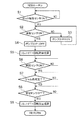
次いで、図9を参照し、筐体1a,1bの開閉に係る制御ルーチンについて説明する。当該制御ルーチンは、プリンタ1の電源がONの間、制御部100により繰り返し実行される。また、当該制御ルーチンの開始時において、ソレノイド70aは回転禁止位置にある。
Next, a control routine for opening and closing the
制御部100は、先ず、ロック解除センサ70SがON信号を出力したか(即ち、ユーザがボタン72bを押下したか)否かを判断する(S1)。ロック解除センサ70SがON信号を出力していないと判断した場合(S1:NO)、制御部100は、S1の処理を繰り返す。ロック解除センサ70SがON信号を出力したと判断した場合(S1:YES)、制御部100は、液面センサ52SがON信号を出力したか(即ち、サブタンク52に所定量以上のインクが貯留されているか)否かを判断する(S2)。
The
液面センサ52SがON信号を出力していないと判断した場合(S2:NO)、制御部100は、ポンプ51P1がOFF状態の場合はON状態に切り換え、ポンプ51P1がON状態の場合はON状態を保持させる(S3)。ポンプ51P1がON状態にされることにより、メインタンク51からサブタンク52にインクが供給される。S3の後、制御部100は、処理をS2に戻す。液面センサ52SがON信号を出力したと判断した場合(S2:YES)、制御部100は、ポンプ51P1をON状態からOFF状態に切り換える(S4)。
When determining that the
S4の後、制御部100は、ソレノイド70aが回転許容位置を取るように制御する(S5)。これにより、ソレノイド70aが回転禁止位置から回転許容位置に移動し、回転部材71の回転が許容された状態となり、ユーザがツマミ72を回転させて第1筐体1aを第1位置から第2位置に向けて移動させることが可能となる。
After S4, the
S5の後、制御部100は、開閉センサ2SがON信号を出力したか(即ち、第1筐体1aが第1位置から第2位置に向かう移動を開始したか)否かを判断する(S6)。開閉センサ2SがON信号を出力していないと判断した場合(S6:NO)、制御部100は、S6の処理を繰り返す。
After S5, the
開閉センサ2SがON信号を出力したと判断した場合(S6:YES)、制御部100は、ジャム処理が完了したか否かを判断する(S7)。例えば、制御部100は、対向位置Aにおける用紙Pの有無を検知するセンサから用紙無しを示す信号を受信したときに、ジャム処理が完了したと判断してよい。ジャム処理が完了していないと判断した場合(S7:NO)、制御部100は、S7の処理を繰り返す。
When it is determined that the open /
ジャム処理が完了したと判断した場合(S7:YES)、制御部100は、開閉センサ2SがOFF信号を出力したか(即ち、第1筐体1aが第1位置にあるか)否かを判断する(S8)。開閉センサ2SがOFF信号を出力していないと判断した場合(S8:NO)、制御部100は、S8の処理を繰り返す。
When determining that the jam processing has been completed (S7: YES), the
開閉センサ2SがOFF信号を出力したと判断した場合(S8:YES)、制御部100は、ソレノイド70aが回転禁止位置を取るように制御する(S9)。これにより、ソレノイド70aが回転許容位置から回転禁止位置に移動し、回転部材71の回転が禁止された状態となり、ユーザがツマミ72を回転させて第1筐体1aを第1位置から第2位置に向けて移動させることが不能となる。S9の後、制御部100は、当該ルーチンを終了する。
When it is determined that the open /
以上に述べたように、本実施形態によれば、第2筐体1bにサブタンク52を支持させたことで、第1筐体1aの重量を軽減することができる。これにより、第1筐体1aを移動させる作業を容易にすることができると共に、回動軸1xにかかる負荷を軽減することができる。
As described above, according to the present embodiment, the weight of the
また、搬送方向における記録ヘッド10と軸線1x1との距離を小さくしたことで、第1筐体1aが回動するときの記録ヘッド10の鉛直方向の移動量を小さくすることができる。これにより、第1筐体1aの回動に伴う水頭差の変動を抑制し、メニスカスの破損を抑制することができる。
In addition, by reducing the distance between the
また、サブタンク52を、廃液受容部材40の下方に配置するのではなく、搬送方向に廃液受容部材40と並んで配置したことで、水頭差を比較的小さくし、メニスカスの破損を抑制することができる。なお、サブタンク52の液面が記録ヘッド10の吐出面10xよりも上方に位置すると、メニスカスが破損してしまう。これを防止するため、サブタンク52の液面が記録ヘッド10の吐出面10xよりも下方に位置するようにサブタンク52を配置して、記録ヘッド10内のインクに背圧をかけることが望ましい。しかしながら、サブタンク52の液面が記録ヘッド10の吐出面10xよりも下方に位置し過ぎると、記録ヘッド10内のインクにかかる背圧が過大になり、メニスカスが破損してしまう。
In addition, the sub-tank 52 is not disposed below the waste
さらに、サブタンク52を、第1方向に廃液受容部材40と並んで配置するのではなく、搬送方向に廃液受容部材40と並んで配置したことで、第1方向の大型化を抑制することができる。また本実施形態では、搬送方向においてサブタンク52が搬送経路Rの領域内に収まっているため(図5参照)、プリンタ1の搬送方向の大型化を回避できる。
Furthermore, by arranging the sub-tank 52 not in the first direction alongside the waste
また、搬送方向における記録ヘッド10と軸線1x1との距離を小さくしたことで、記録ヘッド10と対向する位置に配置される廃液受容部材40と軸線1x1との距離も小さくなるため、廃液受容部材40と回動軸1xとの間にサブタンク52を設置するためのスペースを設けることが困難となる。しかしながら、本実施形態では、搬送方向においてサブタンク52を記録ヘッド10よりも軸線1x1から遠くに配置したため、廃液受容部材40と回動軸1xとの間にサブタンク52を設置するためのスペースを設ける必要はない。つまり、本実施形態によれば、サブタンク52を設置するためのスペースを確保しつつ、第1筐体1aが回動するときの記録ヘッド10の鉛直方向の移動量(ひいては水頭差の変動)を抑え、メニスカスの破損を抑制することができる。
Further, since the distance between the
廃液タンク53が第2筐体1bに支持されている。廃液タンク53は、記録ヘッド10から吐出されたインクを貯留するため、記録ヘッド10よりも下方にあることが好ましく、また、貯留されるインクの量に応じて重量が変動し得ることから、装置全体の重量バランスを取るため、下方に配置することが好ましい。
A
サブタンク52及び廃液タンク53は、第1方向に沿って並んで配置され、且つ、それぞれ搬送方向にプラテン20と並んで配置されている。この場合、サブタンク52及び廃液タンク53をそれぞれ記録ヘッド10及びプラテン20の近くに配置することができる。これにより、連通管52t1及び連通管53tの両方を短くすることができ、ひいては各連通管における気泡の発生を抑制することができる。
The
なお、廃液タンク53は、廃液受容部材40に受容されたインクを貯留するためのものであるため、廃液受容部材40の近傍に配置されるのが好ましい。ここで、廃液タンク53の配置場所について、検討する。廃液タンク53を第1方向に廃液受容部材40と並んで配置すると、第1方向において、廃液受容部材40の領域(≒記録ヘッド10の領域)に加えて廃液タンク53の領域を確保する必要が生じ得るため、プリンタ1が第1方向に大型化し得る。一方、搬送方向においては、搬送経路Rの領域を確保する必要があるが、廃液受容部材40を搬送経路Rの領域内に配置できれば、プリンタ1が搬送方向に大型化することを回避できる。次に、廃液タンク53を廃液受容部材40の下方に配置する構成について考察する。当該構成においては、プリンタ1が搬送方向に大型化することは回避できるものの、廃液受容部材40の下方に廃液タンク53を配置するためのスペースを設ける必要があり、プリンタ1が第2方向に大型化し得る。そこで、廃液タンク53を搬送方向に廃液受容部材40と並んで配置する構成について考察する。当該構成において、搬送方向における記録ヘッド10と軸線1x1との距離を小さくしようとすると、廃液受容部材40と軸線1x1との間に廃液タンク53を配置するためのスペースを設けることが困難となる。そこで、本実施形態では、サブタンク52及び廃液タンク53を、第1方向に沿って並んで配置し、且つ、それぞれ搬送方向にプラテン20と並んで配置している。廃液タンク53を第1方向に沿ってサブタンク52と並んで配置することで、プリンタ1の第1方向の大型化、搬送方向の大型化、及び、第2方向の大型化を抑制することが可能となる。
Note that the
連通管52t1は、サブタンク52における第1方向に廃液タンク53と対向する側とは反対側(図1の手前側)から延出し、連通管53tは、廃液タンク53における第1方向にサブタンク52と対向する側とは反対側(図1の奥側)から延出している。この場合、連通管52t1及び連通管53tの両方をより確実に短くすることができ、ひいては各連通管における気泡の発生をより確実に抑制することができる。
The communication pipe 52t1 extends in the first direction of the sub-tank 52 from the side opposite to the side facing the waste liquid tank 53 (the front side in FIG. 1). It extends from the opposite side (the far side in FIG. 1) from the opposite side. In this case, both the communication pipe 52t1 and the
プリンタ1は、連通管52t1に設けられ、サブタンク52のインクを記録ヘッド10に供給するためのポンプ52Pと、連通管53tに設けられ、廃液受容部材40に受容されたインクを廃液タンク53に供給するためのポンプ53Pとを備えている。この場合、ポンプ52P,53Pが設けられる各連通管52t1,53tの長さが短いため、各ポンプ52P,53Pの負荷が小さくなり、低コスト化を実現することができる。
The
搬送経路Rは、搬送方向上流に向かって凸となる第1湾曲部R1と、搬送方向に沿って延在する直線部R3と、搬送方向下流に向かって凸となる第2湾曲部R2とを含むS字形状である(図5参照)。また、記録ヘッド10は、軸線1x1よりも搬送方向上流且つサブタンク52よりも搬送方向下流において直線部R3に沿って配置されており、第1筐体1aが第2位置にある状態において、直線部R3が露出される。この場合、搬送経路Rを上記のようなS字形状としたことで、第2方向から見た装置面積の小型化を実現することができる。また、第1筐体1aを第2位置に配置し、直線部R3を露出させて、ジャム処理を容易に行うことができる。さらに、記録ヘッド10がサブタンク52よりも搬送方向下流にあるため、記録ヘッド10がサブタンク52よりも搬送方向上流にある場合に比べ、記録ヘッド10と軸線1x1との距離を小さくすることができる。
The transport route R includes a first curved portion R1 that is convex toward the upstream in the transport direction, a linear portion R3 that extends along the transport direction, and a second curved portion R2 that is convex toward the downstream in the transport direction. It has an S-shape (see FIG. 5). Further, the
格納部51xが第1筐体1aに設けられており、第1筐体1aの側面1a1に設けられた開口部1eを介して、メインタンク51を格納部51xに格納可能である。この場合、第1筐体1aの側面1a1に開口部1eが形成されているため、格納部51xに対するメインタンク51の着脱を、開口部1eを介して容易に行うことができる。
The
第1筐体1aの2つの側面1a1,1a2のうち、第1筐体1aが第1位置にある状態において搬送方向における軸線1x1との距離が大きい方の側面に、メインタンク51を格納部51xに格納可能な開口部1eが設けられている。第1筐体1aの軸線1x1から遠い方の側面1a1は、筐体1a,1bの回動構造上、ジャム処理時にユーザが対向し易い面である。上記構成によれば、ジャム処理作業とメインタンク51の着脱作業とを同一の側面から行うことができ、操作性がよい。
The
第1筐体1aが第1位置にある状態において、搬送方向における記録ヘッド10と軸線1x1との距離D10が格納部51xと軸線1x1との距離D51xよりも小さい(図5参照)。この場合、より確実に、記録ヘッド10を軸線1x1の近くに配置することができるため、第1筐体1aの回動に伴う水頭差の変動を抑え、メニスカスの破損を抑制することができる。また、記録ヘッド10を軸線の近くに配置したことで生じたスペースに格納部51xを設けることで、スペースの有効利用を図ることができる。
When the
制御部100は、図9に示すように、ロック解除センサ70SからON信号を受信すると(S1:YES)、サブタンク52に所定量以上のインクが貯留されるまで、メインタンク51からサブタンク52にインクが供給されるようにポンプ51P1を制御する(S2〜S4)。この場合、第1筐体1aの移動に伴う水頭差の変動をより確実に抑制することができる。
As shown in FIG. 9, when the
制御部100は、ロック解除センサ70SからON信号を受信すると(S1:YES)、液面センサ52SからON信号を受信する(S2:YES)まで、メインタンク51からサブタンク52にインクが供給されるようにポンプ51P1を制御する。この場合、液面センサ52Sを用いて制御を行うことで、第1筐体1aの移動に伴う水頭差の変動をより実効的に抑制することができる。
When receiving an ON signal from unlock sensor 70S (S1: YES),
制御部100は、ロック解除センサ70SからON信号を受信すると(S1:YES)、サブタンク52に所定量以上のインクが貯留されるまで、ソレノイド70aを回転禁止位置に保持し、第1筐体1aの第1位置から第2位置に向かう移動が禁止されるようにロック機構70を制御する。この場合、第1筐体1aの移動が実際に行われる前にサブタンク52に所定量以上のインクを貯留しておくことで、第1筐体1aの移動に伴う水頭差の変動をより確実に抑制することができる。
When receiving the ON signal from the unlock sensor 70S (S1: YES), the
続いて、図10を参照し、本発明の第2実施形態に係るインクジェット式プリンタについて説明する。第2実施形態に係るプリンタは、ロック解除センサ70Sの代わりに開閉センサ2Sを第1信号出力部として用い、開閉センサ2Sが出力するON信号を第1信号として筐体1a,1bの開閉に係る制御ルーチンを行う点を除き、第1実施形態に係るプリンタ1と同じ構成である。第2実施形態では、ロック解除センサ70S及びロック機構70を省略してもよい。
Next, an ink jet printer according to a second embodiment of the present invention will be described with reference to FIG. The printer according to the second embodiment uses the open /
第2実施形態では、当該制御ルーチンにおいて、制御部100は、先ず、開閉センサ2SがON信号を出力したか(即ち、第1筐体1aが第1位置から第2位置に向かう移動を開始したか)否かを判断する(S21)。開閉センサ2SがON信号を出力していないと判断した場合(S21:NO)、制御部100は、S21の処理を繰り返す。
In the second embodiment, in the control routine, the
開閉センサ2SがON信号を出力したと判断した場合(S21:YES)、制御部100は、液面センサ52SがON信号を出力したか(即ち、サブタンク52に所定量以上のインクが貯留されているか)否かを判断する(S22)。
When it is determined that the open /
液面センサ52SがON信号を出力していないと判断した場合(S22:NO)、制御部100は、ポンプ51P1を駆動させる(S23)。これにより、メインタンク51からサブタンク52にインクが供給される。S23の後、制御部100は、処理をS22に戻す。液面センサ52SがON信号を出力したと判断した場合(S22:YES)、制御部100は、ポンプ51P1の駆動を停止させる(S24)。S24の後、制御部100は、当該ルーチンを終了する。
When determining that the
本実施形態によれば、制御部100は、開閉センサ2SからON信号を受信すると(S21:YES)、サブタンク52に所定量以上のインクが貯留されるまで、メインタンク51からサブタンク52にインクが供給されるようにポンプ51P1を制御する(S22〜S24)。この場合、第1実施形態と同様、第1筐体1aの移動に伴う水頭差の変動をより確実に抑制することができる。
According to the present embodiment, when the
また、制御部100は、開閉センサ2SからON信号を受信すると(S21:YES)、液面センサ52SからON信号を受信する(S22:YES)まで、メインタンク51からサブタンク52にインクが供給されるようにポンプ51P1を制御する。この場合、第1実施形態と同様、液面センサ52Sを用いて制御を行うことで、第1筐体1aの移動に伴う水頭差の変動をより実効的に抑制することができる。
When receiving an ON signal from open /
続いて、図11を参照し、本発明の第3実施形態に係るインクジェット式プリンタについて説明する。第3実施形態に係るプリンタは、ロック解除センサ70Sや開閉センサ2Sからの信号ではなく液面センサ52Sからの信号に基づいて筐体1a,1bの開閉に係る制御ルーチンを行う点を除き、第1実施形態に係るプリンタ1と同じ構成である。第3実施形態では、ロック解除センサ70S及び開閉センサ2Sを省略してもよい。
Subsequently, an inkjet printer according to a third embodiment of the present invention will be described with reference to FIG. The printer according to the third embodiment differs from the printer according to the third embodiment in that a control routine for opening and closing the
第3実施形態では、当該制御ルーチンにおいて、制御部100は、先ず、液面センサ52SがON信号を出力したか(即ち、サブタンク52に所定量以上のインクが貯留されているか)否かを判断する(S31)。液面センサ52SがON信号を出力していないと判断した場合(S31:NO)、制御部100は、ソレノイド70aが回転禁止位置を取るように制御する(S32)。S32の後、制御部100は、処理をS31に戻す。
In the third embodiment, in the control routine, the
液面センサ52SがON信号を出力したと判断した場合(S31:YES)、制御部100は、ソレノイド70aが回転許容位置を取るように制御する(S33)。S33の後、制御部100は、当該ルーチンを終了する。
When determining that the
本実施形態によれば、制御部100は、液面センサ52SからON信号を受信しているときのみ、第1筐体1aの第1位置から第2位置に向かう移動が許容されるようにロック機構70を制御する(S31〜S33)。この場合、第1筐体1aの移動に伴う水頭差の変動をより確実に抑制することができる。
According to the present embodiment, the
続いて、図12を参照し、本発明の第4実施形態に係るインクジェット式プリンタについて説明する。第4実施形態に係るプリンタは、筐体1a,1bの開閉に係る制御ルーチンにおいて、ロック解除センサ70Sからの信号に基づいて、サブタンク52に所定量以上のインクが貯留されるような制御を行う代わりに、記録ヘッド10の第2方向の位置を変更する制御を行う点を除き、第1実施形態に係るプリンタ1と同じ構成である。第4実施形態では、開閉センサ2S及び液面センサ52Sを省略してもよい。
Subsequently, an inkjet printer according to a fourth embodiment of the present invention will be described with reference to FIG. The printer according to the fourth embodiment performs control such that a predetermined amount or more of ink is stored in the
第4実施形態では、当該制御ルーチンにおいて、制御部100は、先ず、ロック解除センサ70SがON信号を出力したか(即ち、ユーザがボタン72bを押下したか)否かを判断する(S41)。ロック解除センサ70SがON信号を出力していないと判断した場合(S41:NO)、制御部100は、S41の処理を繰り返す。
In the fourth embodiment, in the control routine, the
ロック解除センサ70SがON信号を出力したと判断した場合(S41:YES)、制御部100は、記録ヘッド10が記録位置(図5に実線で示す位置)を取るようにヘッド昇降機構11を制御する(S42)。S42の後、制御部100は、当該ルーチンを終了する。
When it is determined that the unlock sensor 70S has output the ON signal (S41: YES), the
本実施形態によれば、制御部100は、ロック解除センサ70SからON信号を受信すると(S41:YES)、所定範囲内において吐出面10xと対向面20xとの距離が最も小さい位置である記録位置に記録ヘッド10が位置するようにヘッド昇降機構11を制御する(S42)。この場合、第1筐体1aの移動に伴う水頭差の変動をより確実に抑制することができる。
According to the present embodiment, when the
続いて、図13及び図14を参照し、本発明の第5実施形態に係るインクジェット式プリンタ501について説明する。プリンタ501は、サブタンク52及び廃液タンク53の配置を除き、第1実施形態に係るプリンタ1と同じ構成である。第5実施形態において、サブタンク52及び廃液タンク53は、第2方向に沿って並んで配置され、サブタンク52は、廃液タンク53よりも上方にある。この場合、サブタンク52と記録ヘッド10との水頭差を小さくして、メニスカスの破損を抑制することができる。
Next, an
以上、本発明の好適な実施の形態について説明したが、本発明は上述の実施形態に限られるものではなく、特許請求の範囲に記載した限りにおいて様々な設計変更が可能なものである。 The preferred embodiment of the present invention has been described above. However, the present invention is not limited to the above-described embodiment, and various design changes can be made within the scope of the claims.
・本発明は、プリンタに限定されず、ファクシミリやコピー機等にも適用可能である。
・記録媒体は、用紙に限定されず、シート状で記録可能である限りは、任意の媒体(例えば布等)であってよい。
・記録ヘッドの数は、任意であり、1つに限定されず、複数であってもよい。
・記録ヘッドは、吐出面をそれぞれ有する複数のヘッド要素が千鳥状に並んで配置された形態であってもよい。
・搬送機構は、上述の実施形態のようなローラ対を含む構成の他、記録媒体を支持しつつ走行するベルトを含む構成、ローラ対及びベルトの両方を含む構成等、任意の構成であってよい。
・収容部は、記録装置の筐体に対して着脱不能であってもよい。
・第3貯留部は、記録装置の筐体に対して着脱可能(カートリッジ式)及び着脱不能(固定式)のいずれでもよい(上述の実施形態は前者に該当する)。
・また、第3貯留部は、任意の液体を貯留してよく、また、上述の実施形態では2種類の液体(インク及び加湿液)を貯留するが、1種類のみ又は3種類以上の液体を貯留してもよい。
・供給機構は、上述の実施形態のようなポンプを含む構成の他、バルブを含む構成、ポンプ及びバルブの両方を含む構成等、任意の構成であってよい。
・収容部及び受容部は、第1筐体及び第2筐体のいずれに支持されてもよく、例えば、収容部が第1筐体に支持され、受容部が第2筐体に支持されてもよい。
・廃液受容部材は、パージ時に限定されずフラッシング時に、吐出口から吐出された液体を受容してもよい。
・廃液受容部材は、箱状に限定されず、任意の形状であってよく、また、受容した液体を吸収する吸収体等を含んでもよい。
・ワイプ位置に代えて、退避位置(記録ヘッドが吐出面と対向する領域を通過するワイパと接触しないように退避するための位置)を採用してもよい。また、本発明の記録装置は、ヘッド昇降機構を含まなくてもよい。
・対向部材は、2枚のプレートを含むと共に対向面形成位置と開放位置とを取り得る構成に限定されず、例えば1枚のプレートを含むと共に常に対向面形成位置を取る構成であってもよい。この場合、パージ時、フラッシング時等に吐出口から吐出された液体は、当該1枚のプレートの表面が構成する対向面に受容されてよい。そして、対向面に受容された液体は、対向部材の側方から流れ落ちて廃液受容部材に受容され、連通管を通って第2貯留部に移動してもよい。
・制御部は、第1貯留部に所定量以上の液体が貯留されるまで、第3貯留部から第1貯留部に液体が供給されるように供給機構を制御するにあたって、第2信号出力部からの信号を用いることに限定されない。例えば、制御部は、種々のデータ(記録の履歴データ等)に基づいて吐出口から吐出された液体の量(消費量)を算出し、当該消費量に相当する量の液体が第1貯留部に供給されるように供給機構を制御してもよい。
・第1信号出力部に関する第1筐体の移動が開始される前の「所定条件」として、上述の実施形態では「ボタン72bが押下されたこと」を例示したが、「所定条件」は、これに限定されず、ロック機構によるロックが解除されたこと、ジャムが検知されたこと等であってもよい。
・第4実施形態のS41において、ロック解除センサ70Sではなく開閉センサ2SがON信号を出力したか否かを判断してもよい。
・制御部は、各信号出力部からの信号に基づく制御を行わなくてもよい。
The present invention is not limited to printers, but is also applicable to facsimile machines, copiers, and the like.
-The recording medium is not limited to paper, and may be any medium (for example, cloth or the like) as long as it can be recorded in a sheet shape.
-The number of recording heads is arbitrary, is not limited to one, and may be plural.
The recording head may have a form in which a plurality of head elements each having an ejection surface are arranged in a staggered manner.
The transport mechanism may have any configuration such as a configuration including a belt running while supporting a recording medium, a configuration including both a roller pair and a belt, in addition to a configuration including a roller pair as in the above-described embodiment. Good.
-The accommodating part may not be attachable / detachable with respect to the housing | casing of a recording device.
The third storage unit may be detachable (cartridge type) or non-removable (fixed type) with respect to the housing of the recording apparatus (the above-described embodiment corresponds to the former).
The third storage unit may store an arbitrary liquid, and stores two types of liquids (ink and humidifying liquid) in the above-described embodiment, but stores only one type or three or more types of liquids. May be stored.
The supply mechanism may have any configuration, such as a configuration including a valve, a configuration including both a pump and a valve, in addition to the configuration including the pump as in the above-described embodiment.
The housing section and the receiving section may be supported by either the first housing or the second housing. For example, the housing section is supported by the first housing, and the receiving section is supported by the second housing. Is also good.
The waste liquid receiving member is not limited to the time of purging, and may receive the liquid discharged from the discharge port at the time of flushing.
The waste liquid receiving member is not limited to the box shape, may have any shape, and may include an absorber for absorbing the received liquid.
Instead of the wipe position, a retract position (a position for retracting the recording head so as not to contact the wiper passing through the area facing the ejection surface) may be adopted. Further, the recording apparatus of the present invention may not include the head elevating mechanism.
-The opposing member is not limited to a configuration including two plates and can take the opposing surface forming position and the open position. For example, the opposing member may include a single plate and always have the opposing surface forming position. . In this case, the liquid discharged from the discharge port at the time of purging, flushing, or the like may be received by the facing surface formed by the surface of the one plate. Then, the liquid received on the opposing surface may flow down from the side of the opposing member, be received by the waste liquid receiving member, and move to the second reservoir through the communication pipe.
The control unit controls the supply mechanism such that the liquid is supplied from the third storage unit to the first storage unit until a predetermined amount or more of the liquid is stored in the first storage unit. It is not limited to using signals from For example, the control unit calculates the amount (consumption) of the liquid ejected from the ejection port based on various data (recording history data and the like), and the amount of the liquid corresponding to the consumption is stored in the first storage unit. The supply mechanism may be controlled so as to be supplied to the hopper.
In the above-described embodiment, the “predetermined condition” before the start of the movement of the first housing with respect to the first signal output unit is “
In S41 of the fourth embodiment, it may be determined whether or not the open /
-The control part does not need to perform control based on the signal from each signal output part.
1;501 インクジェット式プリンタ(記録装置)
1a 第1筐体
1a1 側面
1b 第2筐体
1c 収容部
1d 受容部
1e 開口部
1x 回動軸
1x1 軸線
2S 開閉センサ(第1信号出力部)
10 記録ヘッド
10x 吐出面
11 ヘッド昇降機構(移動機構)
20 プラテン(対向部材)
20x 対向面
30 搬送機構
40 廃液受容部材
51 メインタンク(第3貯留部)
51x 格納部
51P1 ポンプ(供給機構)
52 サブタンク(第1貯留部)
52P ポンプ(第1ポンプ)
52t1 連通管(第1連通管)
52S 液面センサ(第2信号出力部)
52x インク貯留室(液体貯留室)
53 廃液タンク(第2貯留部)
53P ポンプ(第2ポンプ)
53t 連通管(第2連通管)
70 ロック機構
70S ロック解除センサ(第1信号出力部)
100 制御部
A 対向位置
P 用紙(記録媒体)
1: 501 Inkjet printer (recording device)
1a First housing 1a1
20 Platen (opposite member)
20x opposing
51x storage unit 51P1 pump (supply mechanism)
52 sub tank (first storage unit)
52P pump (first pump)
52t1 communication pipe (first communication pipe)
52S liquid level sensor (second signal output unit)
52x ink storage chamber (liquid storage chamber)
53 Waste liquid tank (second storage unit)
53P pump (second pump)
53t communication pipe (second communication pipe)
70 lock mechanism 70S unlocking sensor (first signal output unit)
100 control unit A facing position P paper (recording medium)
Claims (5)
前記搬送機構によって搬送される記録媒体を収容する収容部と、
液体を貯留し且つ大気と連通可能な液体貯留室を有する第1貯留部と、
前記第1貯留部から供給された液体を吐出するための吐出口が形成された吐出面を有し、前記搬送機構によって搬送される記録媒体が前記吐出面と対向する対向位置を通過するときに記録媒体に向かって前記吐出口から液体を吐出し、記録媒体に画像を記録する記録ヘッドと、
前記対向位置を挟んで前記記録ヘッドと反対側に配置され、前記吐出口から吐出された液体を受容する廃液受容部材と、
前記吐出口から吐出された液体を貯留するための第2貯留部と、
前記記録ヘッドを支持する第1筐体と、
前記第1貯留部、前記第2貯留部及び前記廃液受容部材を支持する第2筐体と、
前記搬送機構によって搬送されて前記対向位置を通過した記録媒体を受容する受容部と、
前記収容部から前記対向位置を通過して前記受容部に向かって形成され、記録媒体が搬送される搬送経路と、を備えており、
前記第1筐体は、前記記録ヘッドによる記録が行われるときの位置である第1位置と、前記第1位置にあるときよりも前記吐出面と前記廃液受容部材との距離が大きい位置である第2位置とを取り得るように、記録媒体の搬送方向と直交し且つ前記吐出面と平行な第1方向に沿った軸線を中心に回動することで、前記第2筐体に対して移動可能であり、
前記第1貯留部が前記搬送方向に前記廃液受容部材と並んで配置されており、前記第1筐体が前記第1位置にある状態において前記搬送方向における前記記録ヘッドと前記軸線との距離が前記第1貯留部と前記軸線との距離よりも小さく、
前記第1貯留部は、前記搬送方向において前記搬送経路が形成される領域内に配置されることを特徴とする記録装置。 A transport mechanism for transporting a sheet-shaped recording medium;
An accommodating section for accommodating a recording medium conveyed by the conveying mechanism,
A first storage unit that stores a liquid and has a liquid storage chamber that can communicate with the atmosphere;
The recording medium transported by the transport mechanism has a discharge surface formed with a discharge port for discharging the liquid supplied from the first storage unit, when the recording medium passes through a facing position facing the discharge surface. A recording head that discharges liquid from the discharge port toward a recording medium and records an image on the recording medium,
A waste liquid receiving member that is disposed on the opposite side of the recording head across the facing position and receives liquid discharged from the discharge port;
A second storage unit for storing the liquid discharged from the discharge port,
A first case supporting the recording head;
A second housing that supports the first storage unit, the second storage unit, and the waste liquid receiving member;
A receiving unit that receives the recording medium that has been conveyed by the conveyance mechanism and has passed the opposing position,
A transport path formed from the storage section toward the receiving section through the facing position, and a recording medium is transported,
Wherein the first housing is the location distance is large between the waste receiving member and the discharge surface than the first position is a position, when in the first position when recording by the recording head is performed By moving about an axis along a first direction perpendicular to the conveyance direction of the recording medium and parallel to the ejection surface so as to be able to take the second position, it moves with respect to the second housing. Is possible,
The first storage section is arranged along with the waste liquid receiving member in the transport direction, and a distance between the recording head and the axis in the transport direction in a state where the first housing is at the first position. Smaller than the distance between the first reservoir and the axis,
The recording apparatus according to claim 1, wherein the first storage unit is disposed in an area where the transport path is formed in the transport direction.
前記対向位置において記録媒体を支持する対向面を有する対向部材と、
前記第2貯留部と前記対向部材又は前記廃液受容部材とを連通させる第2連通管とをさらに備えており、
前記第1貯留部及び前記第2貯留部は、前記第1方向に沿って並んで配置され、且つ、それぞれ前記搬送方向に前記対向部材と並んで配置されていることを特徴とする請求項1に記載の記録装置。 A first communication pipe for communicating the first storage section with the recording head;
An opposing member having an opposing surface that supports the recording medium at the opposing position,
A second communication pipe that communicates the second storage part with the facing member or the waste liquid receiving member,
The said 1st storage part and the said 2nd storage part are arrange | positioned along with the said 1st direction, and are respectively arrange | positioned along with the said opposing member in the said conveyance direction, The said 1st storage part. The recording device according to claim 1.
前記第2連通管は、前記第2貯留部における前記第1方向に前記第1貯留部と対向する側とは反対側から延出していることを特徴とする請求項2に記載の記録装置。 The first communication pipe extends from a side opposite to a side facing the second storage section in the first direction in the first storage section,
3. The recording apparatus according to claim 2, wherein the second communication pipe extends in the first direction of the second storage unit from a side opposite to a side facing the first storage unit. 4.
前記第2連通管に設けられ、前記対向部材又は前記廃液受容部材に受容された液体を前記第2貯留部に供給するための第2ポンプとをさらに備えたことを特徴とする請求項3に記載の記録装置。 A first pump provided in the first communication pipe for supplying the liquid in the first storage section to the recording head;
The apparatus according to claim 3, further comprising: a second pump provided in the second communication pipe and configured to supply the liquid received by the facing member or the waste liquid receiving member to the second storage unit. The recording device according to any one of the preceding claims.
前記第1貯留部は、前記第2貯留部よりも上方にあることを特徴とする請求項1に記載の記録装置。 The first storage section and the second storage section are arranged side by side along a second direction orthogonal to the first direction and the transport direction,
The recording apparatus according to claim 1, wherein the first storage unit is located above the second storage unit.
Priority Applications (1)
| Application Number | Priority Date | Filing Date | Title |
|---|---|---|---|
| JP2018172206A JP6645552B2 (en) | 2018-09-14 | 2018-09-14 | Recording device |
Applications Claiming Priority (1)
| Application Number | Priority Date | Filing Date | Title |
|---|---|---|---|
| JP2018172206A JP6645552B2 (en) | 2018-09-14 | 2018-09-14 | Recording device |
Related Parent Applications (1)
| Application Number | Title | Priority Date | Filing Date |
|---|---|---|---|
| JP2014265500A Division JP6402857B2 (en) | 2014-12-26 | 2014-12-26 | Recording device |
Publications (2)
| Publication Number | Publication Date |
|---|---|
| JP2018192814A JP2018192814A (en) | 2018-12-06 |
| JP6645552B2 true JP6645552B2 (en) | 2020-02-14 |
Family
ID=64571068
Family Applications (1)
| Application Number | Title | Priority Date | Filing Date |
|---|---|---|---|
| JP2018172206A Active JP6645552B2 (en) | 2018-09-14 | 2018-09-14 | Recording device |
Country Status (1)
| Country | Link |
|---|---|
| JP (1) | JP6645552B2 (en) |
Family Cites Families (8)
| Publication number | Priority date | Publication date | Assignee | Title |
|---|---|---|---|---|
| JP2005081546A (en) * | 2003-09-04 | 2005-03-31 | Fuji Xerox Co Ltd | Ink supply unit and recorder |
| JP2007105881A (en) * | 2005-10-11 | 2007-04-26 | Graphtec Corp | Inkjet recorder |
| US7845792B2 (en) * | 2007-01-04 | 2010-12-07 | Kabushiki Kaisha Toshiba | Method and apparatus for forming image |
| JP5444843B2 (en) * | 2009-05-26 | 2014-03-19 | ブラザー工業株式会社 | Inkjet recording device |
| US8708482B2 (en) * | 2011-11-30 | 2014-04-29 | Brother Kogyo Kabushiki Kaisha | Liquid ejecting device |
| JP5998719B2 (en) * | 2012-07-31 | 2016-09-28 | ブラザー工業株式会社 | Liquid ejection device |
| JP6402856B2 (en) * | 2014-12-26 | 2018-10-10 | ブラザー工業株式会社 | Recording device |
| JP6402857B2 (en) * | 2014-12-26 | 2018-10-10 | ブラザー工業株式会社 | Recording device |
-
2018
- 2018-09-14 JP JP2018172206A patent/JP6645552B2/en active Active
Also Published As
| Publication number | Publication date |
|---|---|
| JP2018192814A (en) | 2018-12-06 |
Similar Documents
| Publication | Publication Date | Title |
|---|---|---|
| JP4726155B2 (en) | Image forming apparatus | |
| JP4707482B2 (en) | Image forming apparatus and negative pressure maintaining control method in image forming apparatus | |
| JP5343994B2 (en) | Recording device | |
| JP7192313B2 (en) | Liquid supply device and image recording device | |
| JP2020032695A (en) | Liquid supply device and image recording device | |
| JP4610369B2 (en) | Image forming apparatus | |
| JP6402857B2 (en) | Recording device | |
| JP6344234B2 (en) | Recording device | |
| JP6402856B2 (en) | Recording device | |
| JP5668470B2 (en) | Liquid ejection apparatus and program | |
| JP6645552B2 (en) | Recording device | |
| US11220110B2 (en) | Recording apparatus for ejecting liquid including a main tank and a sub tank storing liquid supplied from the main tank | |
| JP6645551B2 (en) | Recording device | |
| JP5880335B2 (en) | Liquid ejection device | |
| JP4782602B2 (en) | Inkjet recording apparatus and inkjet recording method | |
| JP4941334B2 (en) | Inkjet recording device | |
| JP4854242B2 (en) | Image forming apparatus | |
| US20240399755A1 (en) | Ink supplying mechanism and image forming apparatus | |
| JP7635801B2 (en) | LIQUID SUPPLY DEVICE AND IMAGE RECORDING APPARATUS | |
| JP7136310B2 (en) | liquid consumption device | |
| JP7187901B2 (en) | Liquid supply device and image recording device | |
| JP2012158073A (en) | Liquid ejection apparatus | |
| JP2021154491A (en) | Printer and liquid injection method | |
| JP2020032692A (en) | Liquid supply device and image recording device | |
| JP2007254107A (en) | Medium conveying apparatus and recording apparatus provided with the medium conveying apparatus |
Legal Events
| Date | Code | Title | Description |
|---|---|---|---|
| A521 | Written amendment |
Free format text: JAPANESE INTERMEDIATE CODE: A523 Effective date: 20181012 |
|
| A621 | Written request for application examination |
Free format text: JAPANESE INTERMEDIATE CODE: A621 Effective date: 20181012 |
|
| A131 | Notification of reasons for refusal |
Free format text: JAPANESE INTERMEDIATE CODE: A132 Effective date: 20190702 |
|
| A521 | Written amendment |
Free format text: JAPANESE INTERMEDIATE CODE: A523 Effective date: 20190822 |
|
| TRDD | Decision of grant or rejection written | ||
| A01 | Written decision to grant a patent or to grant a registration (utility model) |
Free format text: JAPANESE INTERMEDIATE CODE: A01 Effective date: 20191210 |
|
| A61 | First payment of annual fees (during grant procedure) |
Free format text: JAPANESE INTERMEDIATE CODE: A61 Effective date: 20191223 |
|
| R150 | Certificate of patent or registration of utility model |
Ref document number: 6645552 Country of ref document: JP Free format text: JAPANESE INTERMEDIATE CODE: R150 |