JP6644712B2 - System and method for operation of a pump with supply and dispense sensors, filtration and dispense confirmation, and vacuum priming of a filter - Google Patents
System and method for operation of a pump with supply and dispense sensors, filtration and dispense confirmation, and vacuum priming of a filter Download PDFInfo
- Publication number
- JP6644712B2 JP6644712B2 JP2016569640A JP2016569640A JP6644712B2 JP 6644712 B2 JP6644712 B2 JP 6644712B2 JP 2016569640 A JP2016569640 A JP 2016569640A JP 2016569640 A JP2016569640 A JP 2016569640A JP 6644712 B2 JP6644712 B2 JP 6644712B2
- Authority
- JP
- Japan
- Prior art keywords
- pump
- pressure
- dispense
- fluid
- stage
- Prior art date
- Legal status (The legal status is an assumption and is not a legal conclusion. Google has not performed a legal analysis and makes no representation as to the accuracy of the status listed.)
- Active
Links
- 238000000034 method Methods 0.000 title claims description 66
- 238000001914 filtration Methods 0.000 title claims description 25
- 230000037452 priming Effects 0.000 title claims description 22
- 238000012790 confirmation Methods 0.000 title description 11
- 239000012530 fluid Substances 0.000 claims description 134
- 238000012360 testing method Methods 0.000 claims description 41
- 230000008569 process Effects 0.000 claims description 34
- 238000011049 filling Methods 0.000 claims description 31
- 230000008859 change Effects 0.000 claims description 28
- 238000001514 detection method Methods 0.000 claims description 19
- 230000002829 reductive effect Effects 0.000 claims description 17
- 238000004891 communication Methods 0.000 claims description 15
- 230000001276 controlling effect Effects 0.000 claims description 7
- 230000001105 regulatory effect Effects 0.000 claims description 4
- 238000010926 purge Methods 0.000 description 29
- 235000012431 wafers Nutrition 0.000 description 26
- 238000003860 storage Methods 0.000 description 25
- 230000004888 barrier function Effects 0.000 description 13
- 238000012545 processing Methods 0.000 description 13
- 230000009471 action Effects 0.000 description 12
- 239000004065 semiconductor Substances 0.000 description 9
- 238000012986 modification Methods 0.000 description 8
- 230000004048 modification Effects 0.000 description 8
- 230000000670 limiting effect Effects 0.000 description 7
- 238000012544 monitoring process Methods 0.000 description 7
- 230000003068 static effect Effects 0.000 description 7
- 238000011144 upstream manufacturing Methods 0.000 description 7
- 230000007246 mechanism Effects 0.000 description 6
- 238000002955 isolation Methods 0.000 description 5
- 239000000126 substance Substances 0.000 description 5
- 230000007547 defect Effects 0.000 description 4
- 230000006870 function Effects 0.000 description 4
- 239000007789 gas Substances 0.000 description 4
- 238000004519 manufacturing process Methods 0.000 description 4
- 238000005259 measurement Methods 0.000 description 4
- 238000005086 pumping Methods 0.000 description 4
- 238000006467 substitution reaction Methods 0.000 description 4
- 238000009423 ventilation Methods 0.000 description 4
- 238000007792 addition Methods 0.000 description 3
- 230000008901 benefit Effects 0.000 description 3
- 230000007423 decrease Effects 0.000 description 3
- 238000010586 diagram Methods 0.000 description 3
- 239000007788 liquid Substances 0.000 description 3
- 238000007726 management method Methods 0.000 description 3
- 239000000463 material Substances 0.000 description 3
- 239000012528 membrane Substances 0.000 description 3
- 230000008707 rearrangement Effects 0.000 description 3
- 230000009286 beneficial effect Effects 0.000 description 2
- 238000013500 data storage Methods 0.000 description 2
- 238000006073 displacement reaction Methods 0.000 description 2
- 230000002093 peripheral effect Effects 0.000 description 2
- 229920000642 polymer Polymers 0.000 description 2
- 238000011045 prefiltration Methods 0.000 description 2
- 230000002441 reversible effect Effects 0.000 description 2
- 238000005070 sampling Methods 0.000 description 2
- 230000000007 visual effect Effects 0.000 description 2
- 229920006362 Teflon® Polymers 0.000 description 1
- 230000002411 adverse Effects 0.000 description 1
- 230000004075 alteration Effects 0.000 description 1
- 238000003491 array Methods 0.000 description 1
- 238000000429 assembly Methods 0.000 description 1
- 230000000712 assembly Effects 0.000 description 1
- 238000009530 blood pressure measurement Methods 0.000 description 1
- 238000004364 calculation method Methods 0.000 description 1
- 239000000919 ceramic Substances 0.000 description 1
- 238000005234 chemical deposition Methods 0.000 description 1
- 239000003795 chemical substances by application Substances 0.000 description 1
- 238000000576 coating method Methods 0.000 description 1
- 238000013329 compounding Methods 0.000 description 1
- 230000006837 decompression Effects 0.000 description 1
- 230000003247 decreasing effect Effects 0.000 description 1
- 230000002950 deficient Effects 0.000 description 1
- 230000006866 deterioration Effects 0.000 description 1
- 230000000694 effects Effects 0.000 description 1
- 230000008030 elimination Effects 0.000 description 1
- 238000003379 elimination reaction Methods 0.000 description 1
- 238000000671 immersion lithography Methods 0.000 description 1
- 239000012535 impurity Substances 0.000 description 1
- 230000010365 information processing Effects 0.000 description 1
- 230000000116 mitigating effect Effects 0.000 description 1
- 230000006911 nucleation Effects 0.000 description 1
- 238000010899 nucleation Methods 0.000 description 1
- 230000003287 optical effect Effects 0.000 description 1
- 229920002120 photoresistant polymer Polymers 0.000 description 1
- 230000000704 physical effect Effects 0.000 description 1
- 239000012196 polytetrafluoroethylene based material Substances 0.000 description 1
- 239000011148 porous material Substances 0.000 description 1
- 238000003825 pressing Methods 0.000 description 1
- 230000002265 prevention Effects 0.000 description 1
- 238000003908 quality control method Methods 0.000 description 1
- 230000004044 response Effects 0.000 description 1
- 238000005096 rolling process Methods 0.000 description 1
- 238000012163 sequencing technique Methods 0.000 description 1
- 239000007858 starting material Substances 0.000 description 1
- 238000007619 statistical method Methods 0.000 description 1
- 230000001360 synchronised effect Effects 0.000 description 1
- 230000001960 triggered effect Effects 0.000 description 1
- 238000012795 verification Methods 0.000 description 1
- XLYOFNOQVPJJNP-UHFFFAOYSA-N water Substances O XLYOFNOQVPJJNP-UHFFFAOYSA-N 0.000 description 1
Images


Classifications
-
- F—MECHANICAL ENGINEERING; LIGHTING; HEATING; WEAPONS; BLASTING
- F04—POSITIVE - DISPLACEMENT MACHINES FOR LIQUIDS; PUMPS FOR LIQUIDS OR ELASTIC FLUIDS
- F04B—POSITIVE-DISPLACEMENT MACHINES FOR LIQUIDS; PUMPS
- F04B13/00—Pumps specially modified to deliver fixed or variable measured quantities
-
- F—MECHANICAL ENGINEERING; LIGHTING; HEATING; WEAPONS; BLASTING
- F04—POSITIVE - DISPLACEMENT MACHINES FOR LIQUIDS; PUMPS FOR LIQUIDS OR ELASTIC FLUIDS
- F04B—POSITIVE-DISPLACEMENT MACHINES FOR LIQUIDS; PUMPS
- F04B17/00—Pumps characterised by combination with, or adaptation to, specific driving engines or motors
- F04B17/03—Pumps characterised by combination with, or adaptation to, specific driving engines or motors driven by electric motors
-
- F—MECHANICAL ENGINEERING; LIGHTING; HEATING; WEAPONS; BLASTING
- F04—POSITIVE - DISPLACEMENT MACHINES FOR LIQUIDS; PUMPS FOR LIQUIDS OR ELASTIC FLUIDS
- F04B—POSITIVE-DISPLACEMENT MACHINES FOR LIQUIDS; PUMPS
- F04B19/00—Machines or pumps having pertinent characteristics not provided for in, or of interest apart from, groups F04B1/00 - F04B17/00
- F04B19/04—Pumps for special use
-
- F—MECHANICAL ENGINEERING; LIGHTING; HEATING; WEAPONS; BLASTING
- F04—POSITIVE - DISPLACEMENT MACHINES FOR LIQUIDS; PUMPS FOR LIQUIDS OR ELASTIC FLUIDS
- F04B—POSITIVE-DISPLACEMENT MACHINES FOR LIQUIDS; PUMPS
- F04B23/00—Pumping installations or systems
- F04B23/04—Combinations of two or more pumps
-
- F—MECHANICAL ENGINEERING; LIGHTING; HEATING; WEAPONS; BLASTING
- F04—POSITIVE - DISPLACEMENT MACHINES FOR LIQUIDS; PUMPS FOR LIQUIDS OR ELASTIC FLUIDS
- F04B—POSITIVE-DISPLACEMENT MACHINES FOR LIQUIDS; PUMPS
- F04B43/00—Machines, pumps, or pumping installations having flexible working members
- F04B43/02—Machines, pumps, or pumping installations having flexible working members having plate-like flexible members, e.g. diaphragms
- F04B43/04—Pumps having electric drive
-
- F—MECHANICAL ENGINEERING; LIGHTING; HEATING; WEAPONS; BLASTING
- F04—POSITIVE - DISPLACEMENT MACHINES FOR LIQUIDS; PUMPS FOR LIQUIDS OR ELASTIC FLUIDS
- F04B—POSITIVE-DISPLACEMENT MACHINES FOR LIQUIDS; PUMPS
- F04B49/00—Control, e.g. of pump delivery, or pump pressure of, or safety measures for, machines, pumps, or pumping installations, not otherwise provided for, or of interest apart from, groups F04B1/00 - F04B47/00
- F04B49/10—Other safety measures
-
- F—MECHANICAL ENGINEERING; LIGHTING; HEATING; WEAPONS; BLASTING
- F04—POSITIVE - DISPLACEMENT MACHINES FOR LIQUIDS; PUMPS FOR LIQUIDS OR ELASTIC FLUIDS
- F04B—POSITIVE-DISPLACEMENT MACHINES FOR LIQUIDS; PUMPS
- F04B51/00—Testing machines, pumps, or pumping installations
-
- F—MECHANICAL ENGINEERING; LIGHTING; HEATING; WEAPONS; BLASTING
- F04—POSITIVE - DISPLACEMENT MACHINES FOR LIQUIDS; PUMPS FOR LIQUIDS OR ELASTIC FLUIDS
- F04B—POSITIVE-DISPLACEMENT MACHINES FOR LIQUIDS; PUMPS
- F04B53/00—Component parts, details or accessories not provided for in, or of interest apart from, groups F04B1/00 - F04B23/00 or F04B39/00 - F04B47/00
- F04B53/10—Valves; Arrangement of valves
-
- F—MECHANICAL ENGINEERING; LIGHTING; HEATING; WEAPONS; BLASTING
- F04—POSITIVE - DISPLACEMENT MACHINES FOR LIQUIDS; PUMPS FOR LIQUIDS OR ELASTIC FLUIDS
- F04B—POSITIVE-DISPLACEMENT MACHINES FOR LIQUIDS; PUMPS
- F04B53/00—Component parts, details or accessories not provided for in, or of interest apart from, groups F04B1/00 - F04B23/00 or F04B39/00 - F04B47/00
- F04B53/16—Casings; Cylinders; Cylinder liners or heads; Fluid connections
-
- F—MECHANICAL ENGINEERING; LIGHTING; HEATING; WEAPONS; BLASTING
- F04—POSITIVE - DISPLACEMENT MACHINES FOR LIQUIDS; PUMPS FOR LIQUIDS OR ELASTIC FLUIDS
- F04B—POSITIVE-DISPLACEMENT MACHINES FOR LIQUIDS; PUMPS
- F04B9/00—Piston machines or pumps characterised by the driving or driven means to or from their working members
- F04B9/02—Piston machines or pumps characterised by the driving or driven means to or from their working members the means being mechanical
-
- F—MECHANICAL ENGINEERING; LIGHTING; HEATING; WEAPONS; BLASTING
- F16—ENGINEERING ELEMENTS AND UNITS; GENERAL MEASURES FOR PRODUCING AND MAINTAINING EFFECTIVE FUNCTIONING OF MACHINES OR INSTALLATIONS; THERMAL INSULATION IN GENERAL
- F16H—GEARING
- F16H25/00—Gearings comprising primarily only cams, cam-followers and screw-and-nut mechanisms
- F16H25/18—Gearings comprising primarily only cams, cam-followers and screw-and-nut mechanisms for conveying or interconverting oscillating or reciprocating motions
- F16H25/20—Screw mechanisms
- F16H25/2003—Screw mechanisms with arrangements for taking up backlash
- F16H25/2006—Screw mechanisms with arrangements for taking up backlash with more than one nut or with nuts consisting of more than one bearing part
-
- H—ELECTRICITY
- H01—ELECTRIC ELEMENTS
- H01L—SEMICONDUCTOR DEVICES NOT COVERED BY CLASS H10
- H01L21/00—Processes or apparatus adapted for the manufacture or treatment of semiconductor or solid state devices or of parts thereof
- H01L21/67—Apparatus specially adapted for handling semiconductor or electric solid state devices during manufacture or treatment thereof; Apparatus specially adapted for handling wafers during manufacture or treatment of semiconductor or electric solid state devices or components ; Apparatus not specifically provided for elsewhere
- H01L21/67005—Apparatus not specifically provided for elsewhere
- H01L21/67011—Apparatus for manufacture or treatment
- H01L21/6715—Apparatus for applying a liquid, a resin, an ink or the like
-
- F—MECHANICAL ENGINEERING; LIGHTING; HEATING; WEAPONS; BLASTING
- F04—POSITIVE - DISPLACEMENT MACHINES FOR LIQUIDS; PUMPS FOR LIQUIDS OR ELASTIC FLUIDS
- F04B—POSITIVE-DISPLACEMENT MACHINES FOR LIQUIDS; PUMPS
- F04B2205/00—Fluid parameters
- F04B2205/02—Pressure in the inlet chamber
-
- F—MECHANICAL ENGINEERING; LIGHTING; HEATING; WEAPONS; BLASTING
- F04—POSITIVE - DISPLACEMENT MACHINES FOR LIQUIDS; PUMPS FOR LIQUIDS OR ELASTIC FLUIDS
- F04B—POSITIVE-DISPLACEMENT MACHINES FOR LIQUIDS; PUMPS
- F04B2205/00—Fluid parameters
- F04B2205/50—Presence of foreign matter in the fluid
- F04B2205/503—Presence of foreign matter in the fluid of gas in a liquid flow, e.g. gas bubbles
-
- F—MECHANICAL ENGINEERING; LIGHTING; HEATING; WEAPONS; BLASTING
- F05—INDEXING SCHEMES RELATING TO ENGINES OR PUMPS IN VARIOUS SUBCLASSES OF CLASSES F01-F04
- F05B—INDEXING SCHEME RELATING TO WIND, SPRING, WEIGHT, INERTIA OR LIKE MOTORS, TO MACHINES OR ENGINES FOR LIQUIDS COVERED BY SUBCLASSES F03B, F03D AND F03G
- F05B2210/00—Working fluid
- F05B2210/10—Kind or type
- F05B2210/11—Kind or type liquid, i.e. incompressible
-
- F—MECHANICAL ENGINEERING; LIGHTING; HEATING; WEAPONS; BLASTING
- F05—INDEXING SCHEMES RELATING TO ENGINES OR PUMPS IN VARIOUS SUBCLASSES OF CLASSES F01-F04
- F05B—INDEXING SCHEME RELATING TO WIND, SPRING, WEIGHT, INERTIA OR LIKE MOTORS, TO MACHINES OR ENGINES FOR LIQUIDS COVERED BY SUBCLASSES F03B, F03D AND F03G
- F05B2260/00—Function
- F05B2260/30—Retaining components in desired mutual position
- F05B2260/301—Retaining bolts or nuts
-
- F—MECHANICAL ENGINEERING; LIGHTING; HEATING; WEAPONS; BLASTING
- F05—INDEXING SCHEMES RELATING TO ENGINES OR PUMPS IN VARIOUS SUBCLASSES OF CLASSES F01-F04
- F05B—INDEXING SCHEME RELATING TO WIND, SPRING, WEIGHT, INERTIA OR LIKE MOTORS, TO MACHINES OR ENGINES FOR LIQUIDS COVERED BY SUBCLASSES F03B, F03D AND F03G
- F05B2260/00—Function
- F05B2260/60—Fluid transfer
-
- Y—GENERAL TAGGING OF NEW TECHNOLOGICAL DEVELOPMENTS; GENERAL TAGGING OF CROSS-SECTIONAL TECHNOLOGIES SPANNING OVER SEVERAL SECTIONS OF THE IPC; TECHNICAL SUBJECTS COVERED BY FORMER USPC CROSS-REFERENCE ART COLLECTIONS [XRACs] AND DIGESTS
- Y10—TECHNICAL SUBJECTS COVERED BY FORMER USPC
- Y10S—TECHNICAL SUBJECTS COVERED BY FORMER USPC CROSS-REFERENCE ART COLLECTIONS [XRACs] AND DIGESTS
- Y10S417/00—Pumps
Description
関連出願の相互参照
本出願は、付録を含む、参照により本明細書に完全に組み込まれている、2014年5月28日に出願した米国仮出願第62/004,117号からの優先権の利益を主張するものである。
This application claims the benefit of priority from U.S. Provisional Application No. 62 / 004,117, filed May 28, 2014, which is hereby fully incorporated by reference, including an appendix. Claims.
本開示は、一般的に流体ポンプに関するものである。より具体的には、本明細書で開示されている実施形態は、半導体製造において使用されるポンプを含む、単段または多段ポンプに関するものである。なおいっそう具体的には、本発明の実施形態は、ポンプを操作すること、ならびに/または濾過確認、分注確認、空気検出、およびポンプ内の濾過器の減圧プライミング(reduced pressure priming)を含む、ポンプの様々な動作、もしくはアクションを確認することに関するものである。 The present disclosure relates generally to fluid pumps. More specifically, the embodiments disclosed herein relate to single or multi-stage pumps, including pumps used in semiconductor manufacturing. Still more specifically, embodiments of the present invention include operating a pump and / or including reduced pressure priming, filtration confirmation, dispense confirmation, air detection, and a filter in the pump. It is related to confirming various operations or actions of the pump.
流体がポンプ装置によって分注される量および/または速度の正確な制御が必要になる用途が多数ある。たとえば、半導体加工では、フォトレジスト化学薬品などの、光化学物質が半導体ウェハに塗布される量および速度を制御することは重要である。加工時に半導体ウェハに施されるコーディングは、典型的には、オングストローム単位で測定されるウェハの表面全体にわたって凸凹のない、一貫した平坦さを必要とする。処理化学薬品がウェハに塗布される速度は、処理液(すなわち、化学薬品を含む半導体製造プロセス流体)が正確にかつ均一に塗布されることを確実にするために慎重に較正され、正確に制御されなければならない。 There are many applications where precise control of the amount and / or rate at which fluid is dispensed by the pump device is required. For example, in semiconductor processing, it is important to control the amount and rate at which photochemicals, such as photoresist chemicals, are applied to a semiconductor wafer. Coding applied to semiconductor wafers during processing typically requires a consistent, flat surface without roughness over the entire surface of the wafer, measured in Angstroms. The rate at which processing chemicals are applied to the wafer is carefully calibrated and precisely controlled to ensure that processing liquids (i.e., semiconductor manufacturing process fluids containing chemicals) are applied accurately and uniformly It must be.
半導体産業において使用されている多くの光化学物質は、今日では、原価は非常に高く、1リットルあたり1,000米ドルほどになることも頻繁である。したがって、最小であるが適切な量の化学薬品が使用されること、およびそれらの化学薬品を含む処理液もしくは流体がポンプ装置によってダメージを受けないことを確実にすることが好ましい。しかしながら、ポンプ装置の動作中の様々な状態により、圧力スパイクまたは圧力の降下が生じることがあり、プロセス流体にダメージを与える可能性があり(すなわち、プロセス流体の物理特性を好ましくない特性に変えてしまうおそれがあり)、延いては、分注するプロセス流体が多すぎたり、少なすぎたりするか、またはプロセス流体の分注動作に好ましくないダイナミクスが入り込む可能性がある。ポンプ装置内に生じる他の状態もプロセス流体の適切な分注を妨げ得る。これらの状態は、プロセスそれ自体のタイミングが変化する結果生じ得る。これらの状態が生じた場合、結果として、プロセス流体のウェハへの不適切な分注が生じ、ウェハは使用に適さないものとなり、その結果、最終的に、ウェハはスクラップとして廃棄されることになる。 Many photochemicals used in the semiconductor industry today are very expensive, often as much as $ 1,000 per liter. Therefore, it is preferable to ensure that a minimum but appropriate amount of chemicals is used and that processing solutions or fluids containing those chemicals are not damaged by the pump device. However, various conditions during operation of the pumping device can cause pressure spikes or pressure drops, which can damage the process fluid (i.e., changing the physical properties of the process fluid into undesirable properties). In other words, too much or too little process fluid may be dispensed, or undesired dynamics may enter the process fluid dispensing operation. Other conditions that occur in the pumping system may also prevent proper dispensing of the process fluid. These conditions can result from changes in the timing of the process itself. When these conditions occur, the result is improper dispensing of process fluids into the wafer, making the wafer unusable, and ultimately the wafer is discarded as scrap. Become.
この問題を悪化させるのは、多くの場合において、スクラップウェハは、ウェハがさらに加工された後に何らかの形態の品質管理方法を使用してはじめて検出されるという事実である。その一方で、結果として不適切な分注を引き起こした状態、およびしたがって、スクラップウェハは存続する。その結果、最初の不適切な分注からスクラップウェハの検出までのしばらくの間、多くの追加の不適切な堆積物が他のウェハ上に残っている可能性がある。残念なことに、これらのウェハもまた、スクラップとして破棄されなければならない。 Compounding this problem is the fact that in many cases, scrap wafers are only detected after some further processing of the wafers using some form of quality control method. On the other hand, the condition that resulted in improper dispensing, and thus the scrap wafer, survives. As a result, many additional inappropriate deposits may remain on other wafers for some time between the first inappropriate dispensing and the detection of the scrap wafer. Unfortunately, these wafers must also be scrapped as scrap.
これからわかるように、適切な分注が行われたことを検出または確認することが望ましい。そのような分注確認は、以前には、様々な技術を使用して行われていた。一例として、以前の分注確認方法は、分注が行われたことを確認するためにポンプの分注ノズルのところにあるカメラシステムを利用することを伴う。しかしながら、この解決方法は、最適なものと言えないが、それは、これらのカメラシステムが、通常、ポンプシステムから独立しており、したがって、ポンプシステムと連携させるために別々に取り付け、較正しなければならないからである。さらに、膨大な事例では、これらのカメラシステムは、法外に高価なものとなる傾向がある。 As can be seen, it is desirable to detect or confirm that proper dispensing has been performed. Such dispensing confirmation has previously been performed using a variety of techniques. As an example, previous dispense verification methods involve using a camera system at the dispense nozzle of the pump to confirm that dispense has occurred. However, while this solution is less than optimal, it means that these camera systems are usually independent of the pump system and must therefore be separately mounted and calibrated to work with the pump system. Because it does not become. In addition, in vast cases, these camera systems tend to be prohibitively expensive.
別の方法は、分注が行われたことを確認するためにポンプシステム内のプロセス流体の流体流路内で流量計を使用することを伴う。この方法も、問題になり得る。たとえば、流体流路内に追加のコンポーネントとして流量計を挿入すると、ポンプシステムのコストが増大するだけでなく、挿入された流量計内を貫流するときにプロセス流体が汚染する危険性も増大する。 Another method involves using a flow meter in the fluid flow path of the process fluid in the pump system to confirm that dispensing has occurred. This method can also be problematic. For example, inserting a flow meter as an additional component in the fluid flow path not only increases the cost of the pump system, but also increases the risk of contaminating the process fluid as it flows through the inserted flow meter.
前記の説明を鑑みて、必要とされるものは、ポンプの動作およびアクションを確認するための、これらの動作およびアクションの適切な完了を素早くかつ正確に検出し得る、また効率的な動作および品質結果を確実にするために必要になったときに早期の警告を発しおよび/または適切なアクションを遂行できる、方法およびシステムである。本明細書で開示されている実施形態では、このような必要性およびさらに多くのことに対処することができる。 In view of the foregoing description, what is needed is an efficient operation and quality that can quickly and accurately detect the proper completion of these operations and actions to confirm the operation and actions of the pump. Methods and systems that can provide an early warning and / or take appropriate action when needed to ensure results. The embodiments disclosed herein can address such needs and more.
いくつかの実施形態において、ポンプシステムは、流体源と、入口弁を介して流体源と流体的に連通している多段ポンプと、1つまたは複数のネットワーク通信リンクを介して多段ポンプに通信可能に接続されているポンプコントローラとを備え得る。ポンプコントローラは、また、ポンプトラック(pump track)、管理ステーション(management station)、または同様のものなどの制御デバイスに通信可能に接続され得る。 In some embodiments, the pump system is capable of communicating with a fluid source, a multi-stage pump in fluid communication with the fluid source via an inlet valve, and the multi-stage pump via one or more network communication links. And a pump controller connected to the pump controller. The pump controller may also be communicatively connected to a control device such as a pump track, a management station, or the like.
いくつかの実施形態において、多段ポンプは、プロセス流体の流入を調節するための入口弁と、入口弁から下流にある供給段部分と、供給段部分から下流にある濾過器と、濾過器から下流にある分注段と、プロセス流体の流出を調節するための出口弁とを備え得る。いくつかの実施形態において、供給段部分は、供給段ポンプと、それに取り付けられている圧力センサーとを備え得る。いくつかの実施形態において、供給段部分は、ボトルまたは貯蔵タンクと、それに取り付けられている圧力センサーとを備え得る。圧力センサーは、供給室、ボトル、または貯蔵タンクの側壁に取り付けられ、それにかかる流体圧力を検出することができる。一実施形態において、圧力センサーは、側壁に埋め込み式に取り付けられ得る。いくつかの実施形態において、圧力センサーは、側壁に角度を付けて取り付けられ得る。いくつかの実施形態において、圧力センサーが側壁に取り付けられる角度は、約5から10度、約45度、または空気のトラッピングを回避するために側壁に関して可能な限りの急角度とすることができる。一実施形態において、圧力センサーは、圧力センサーの感知部分が上方を指すように側壁上に取り付けられる。いくつかの実施形態において、圧力センサーは、供給室、ボトル、または貯蔵タンクの半分の高さのところ、またはその付近に取り付けられ得る。いくつかの実施形態において、圧力センサーは、供給室、ボトル、または貯蔵タンクの底部のところ、またはその付近に取り付けられ得る。 In some embodiments, the multi-stage pump includes an inlet valve for regulating the inflow of the process fluid, a supply stage portion downstream from the inlet valve, a filter downstream from the supply stage portion, and a downstream portion from the filter. And an outlet valve for regulating the outflow of process fluid. In some embodiments, the feed stage portion may include a feed stage pump and a pressure sensor attached thereto. In some embodiments, the supply stage portion may comprise a bottle or storage tank and a pressure sensor attached thereto. A pressure sensor is mounted on the side wall of the supply chamber, bottle, or storage tank and can detect fluid pressure on it. In one embodiment, the pressure sensor may be embedded in the sidewall. In some embodiments, the pressure sensor may be mounted at an angle on the side wall. In some embodiments, the angle at which the pressure sensor is mounted to the side wall can be about 5 to 10 degrees, about 45 degrees, or as steep as possible with respect to the side wall to avoid trapping air. In one embodiment, the pressure sensor is mounted on the sidewall such that the sensing portion of the pressure sensor points upward. In some embodiments, the pressure sensor may be mounted at or near half the height of the supply chamber, bottle, or storage tank. In some embodiments, the pressure sensor may be mounted at or near the bottom of a supply chamber, bottle, or storage tank.
供給段ポンプは、供給室と、供給室内で移動し、供給室内のプロセス流体を押しのける供給段ダイアフラムと、供給段ダイアフラムを移動するピストンと、ピストンを作動させるピストンに結合されている送りネジまたはボールネジと、送りネジまたはボールネジを駆動する供給モーターとを備え得る。 The supply stage pump includes a supply chamber, a supply stage diaphragm that moves in the supply chamber and displaces the process fluid in the supply chamber, a piston that moves the supply stage diaphragm, and a feed screw or a ball screw that is coupled to the piston that operates the piston. And a supply motor for driving a feed screw or a ball screw.
いくつかの実施形態において、充填側の圧力センサーによって検出されるような流体圧力は、濾過確認、空気検出試験、および濾過器プライミングルーチンを含む、多くの有益な用途を有し得る。いくつかの実施形態において、濾過確認は、圧力センサーによって検出されるような流体圧力に少なくとも一部は基づき動作充填圧力プロファイルを決定するステップと、動作充填圧力プロファイルを基準充填圧力プロファイルとを比較するステップと、アラームを発生するかどうかを決定するステップとを含み得る。いくつかの実施形態において、空気検出試験は、多段ポンプの一部を隔離するステップと、隔離された部分を第1の圧力にするように供給モーターを制御するステップと、供給モーターを固定された距離だけ移動するステップと、圧力センサーを使用して第2の圧力を検出するステップと、第1の圧力と隔離された部分内の空気の量と相関する第2の圧力との間の変化を指示する差圧を決定するステップとを含むものとしてよい。いくつかの実施形態において、濾過器プライミングルーチンは、多段ポンプの隔離された部分が、陰圧または減圧に到達したかどうかを決定するステップと、一定期間の間陰圧または減圧で濾過器をプロセス流体中に浸けて多段ポンプの隔離された部分におけるプロセス流体から脱気するか、またはガスもしくは気泡を取り除くステップとを含み得る。 In some embodiments, fluid pressure as detected by a fill-side pressure sensor may have many beneficial applications, including filtration confirmation, air detection tests, and filter priming routines. In some embodiments, the filtration confirmation determines the working fill pressure profile based at least in part on the fluid pressure as detected by the pressure sensor, and compares the working fill pressure profile to a reference fill pressure profile. The method may include steps and determining whether to generate an alarm. In some embodiments, the air detection test includes isolating a portion of the multi-stage pump, controlling a supply motor to bring the isolated portion to a first pressure, and fixing the supply motor. Moving a distance, detecting a second pressure using a pressure sensor, and determining a change between the first pressure and a second pressure that correlates to an amount of air in the isolated portion. Determining a differential pressure to be instructed. In some embodiments, the filter priming routine includes determining whether an isolated portion of the multi-stage pump has reached a negative or reduced pressure, and processing the filter at a negative or reduced pressure for a period of time. Submerged in the fluid to degas the process fluid in an isolated portion of the multi-stage pump or to remove gas or bubbles.
いくつかの実施形態において、ポンプシステムは、ポンプコントローラによって監視されている複数のポンプ動作パラメータに対する動作プロファイルを表示するためのグラフィカルユーザインターフェースをさらに備え得る。グラフィカルユーザインターフェースは、情報アラーム、警告アラーム、エラーアラーム、および重大アラームを含む、動作プロファイルに対する複数のユーザ選択可能なアラームタイプを表示し得る。 In some embodiments, the pump system may further comprise a graphical user interface for displaying an operating profile for a plurality of pump operating parameters monitored by the pump controller. The graphical user interface may display multiple user-selectable alarm types for the operation profile, including informational alarms, warning alarms, error alarms, and critical alarms.
いくつかの実施形態において、動作プロファイルは、準備完了、分注、濾過、通気、パージ、空気検出、および充填セグメントを含む分注サイクルで収集された情報を含み得る。特に、いくつかの実施形態において、動作プロファイルは、供給室内の流体圧力に対する圧力プロファイルを含むものとしてよい。 In some embodiments, the operating profile may include information gathered in a dispense cycle including ready, dispense, filter, vent, purge, air detect, and fill segments. In particular, in some embodiments, the operating profile may include a pressure profile for fluid pressure in the supply chamber.
他の多数の実施形態も可能であり得る。 Many other embodiments may be possible.
本発明のこれらおよび他の態様は、以下の説明および添付図面とともに考察すると、よりよく認識され理解されるであろう。次の説明は、本発明の様々な実施形態およびその多数の具体的詳細を指示しているが、例証として、また限定することなく与えられる。多くの代用、修正、追加、または再配置が、本発明の範囲内で行われるものとしてよく、本発明は、そのようなすべての代用、修正、追加、または再配置を含む。 These and other aspects of the invention will be better appreciated and understood when considered in conjunction with the following description and the accompanying drawings. The following description sets forth various embodiments of the present invention and numerous specific details thereof, but is provided by way of illustration and not limitation. Many substitutions, modifications, additions, or rearrangements may be made within the scope of the invention, and the invention includes all such substitutions, modifications, additions, or rearrangements.
本明細書の一部を伴い、形成する図面は、本発明のいくつかの態様を示すために含まれている。本発明、および本発明に付属するシステムのコンポーネントおよび動作のより明らかな印象は、図面に示されている例示的な、したがって非限定的な実施形態を参照することによってより容易に明らかになり、同一の参照番号は、同じコンポーネントを示す。図面に示されている特徴は、必ずしも縮尺通りに描かれていないことに留意されたい。 The drawings accompanying and forming part of this specification are included to illustrate some aspects of the present invention. A clearer impression of the invention and of the components and operation of the system that accompanies the invention will become more readily apparent by reference to the exemplary and thus non-limiting embodiments illustrated in the drawings, in which: Identical reference numbers indicate identical components. Note that the features shown in the figures are not necessarily drawn to scale.
システムおよび方法ならびにその有利な詳細は、添付図面に示され、以下の説明において詳述される非限定的な実施形態を参照しつつより完全に説明される。よく知られている出発原料、加工技術、コンポーネント、および機器の説明は、本発明を詳細にして不要にわかりにくくしないために省かれている。しかしながら、詳細な説明および特定の例は、本発明の好ましい実施例を示しているが、例証としてのみ、また限定することなく与えられていることは理解されるであろう。本開示の精神および/または範囲内の様々な代用、修正、追加、および/または再配置は、本開示から当業者にとって明らかなものとなるであろう。 The system and method and advantageous details thereof are illustrated in the accompanying drawings and are more fully described with reference to the non-limiting embodiments detailed in the following description. Descriptions of well-known starting materials, processing techniques, components, and equipment are omitted so as not to obscure the present invention in unnecessary detail. It will be understood, however, that the detailed description and specific examples, which illustrate preferred embodiments of the present invention, are given by way of illustration only and without limitation. Various substitutions, modifications, additions, and / or rearrangements within the spirit and / or scope of the present disclosure will be apparent to those skilled in the art from the present disclosure.
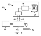
実施形態を説明する前に、様々な実施形態とともに利用され得る例示的なポンプまたはポンプシステムを説明するのは有益であり得る。図1は、ポンプシステム10の図表現である。ポンプシステム10は、流体源15と、ポンプコントローラ20と、多段ポンプ100を備えることができ、これらは流体をウェハ25上に分注するために連携する。流体源15は、タンク、ボトル、流体処理システム、または多段ポンプ100がプロセス流体、たとえば、半導体製造プロセス流体を得る流体搬送ネットワークなどの適切な供給源であってよい。半導体製造プロセスは、当業者に知られており、したがって、本明細書では説明されていない。
Before describing the embodiments, it may be useful to describe an exemplary pump or pump system that may be utilized with the various embodiments. FIG. 1 is a diagrammatic representation of a
多段ポンプ100の動作は、ポンプコントローラ20によって制御されるものとしてよく、これは、オンボード多段ポンプ100であるか、または1つまたは複数の通信リンクを介して多段ポンプ100に接続され、それにより、制御信号、データ、または他の情報を伝達することができる。ポンプコントローラ20は、プロセッサ、メモリ、インターフェース、ディスプレイデバイス、周辺機器、またはコンピュータコンポーネントを含む、当技術分野で知られている様々なコンピュータコンポーネントを備え得る。たとえば、ポンプコントローラ20は、中央演算処理装置(CPU)、特定用途向け集積回路(ASIC)、デジタルシグナルプロセッシング(DSP)、縮小命令セットコンピューティング(RISC)、または他のプロセッサを実装するプロセッサ35を備えることができる。好適なプロセッサの一例は、Texas Instruments社のTMS320F28335PGFA 16-bit DSP(Texas Instrumentsはテキサス州ダラスに本社を置く会社である)。それに加えて、ポンプコントローラ20は、少なくとも1つのコンピュータ可読媒体27(たとえば、ランダムアクセスメモリ(RAM)、リードオンリーメモリ(ROM)、フラッシュメモリ、光ディスク、磁気ドライブ、または他のコンピュータ可読媒体)を備えることができる。
The operation of the
図1の例において、ポンプコントローラ20は、通信リンク40および45を介して多段ポンプ100と通信する。通信リンク40および45は、ネットワーク(たとえば、Ethernet、EtherCAT、ワイヤレスネットワーク、グローバルエリアネットワーク、DeviceNetネットワークまたは技術分野で使用されているか、または開発されている他のネットワーク)、バス(たとえば、小型コンピュータ用周辺機器インターフェース(SCSI)バス)、または他の通信リンクであってよい。これらの通信コンポーネントは、当業者に知られている。
In the example of FIG. 1, the
ポンプコントローラ20は、オンボードプリント基板(PCB)、リモートコントローラとして、または他の好適な方式で実装され得る。ポンプコントローラ20は、ポンプコントローラ20が多段ポンプ100、ポンプトラック、管理ステーションなどと通信できるようにする適切なインターフェース(たとえば、EtherCAT、ネットワークインターフェース、入出力(I/O)インターフェース、アナログ/デジタルコンバータ、および他のコンポーネント)を備え得る。
ポンプトラックは、ウェハ表面上で動作(たとえば、化学的堆積または流体コーティングプロセス)を実行するために必要なハードウェアおよびソフトウェアを備えるツールまたはシステムを指す。そうする際に、ウェハ25の表面に正確な量の流体が塗布される必要がある。ポンプコントローラ20は、多段ポンプ100内の様々な弁およびモーターを制御して、多段ポンプ100が、低粘度流体(すなわち、5センチポアズ)を含む、様々なタイプの流体を正確に分注することを行わせることができる。多段ポンプ100の動作を制御するための制御ロジックは、ポンプコントローラ20、管理ステーション、および/または他のコンピューティングデバイス上で具現化され得る。ポンプコントローラ20において、制御命令30は、非一時的コンピュータ可読媒体27上で具現化され得る。制御方式の例は、参照により本明細書に完全に組み込まれている、米国特許第8,029,247号、名称「SYSTEM AND METHOD FOR PRESSURE COMPENSATION IN A PUMP」、米国特許第7,443,483号、名称「SYSTEMS AND METHODS FOR FLUID FLOW CONTROL IN AN IMMERSION LITHOGRAPHY SYSTEM」、米国特許第8,172,546号、名称「SYSTEM AND METHOD FOR CORRECTING FOR PRESSURE VARIATIONS USING A MOTOR」、米国特許第7,850,431号、名称「SYSTEM AND METHOD FOR CONTROL OF FLUID PRESSURE」、米国特許第7,878,765号、名称「SYSTEM AND METHOD FOR MONITORING OPERATION OF A PUMP」、および米国特許第7,940,664号、名称「I/O SYSTEMS, METHODS AND DEVICES FOR INTERFACING A PUMP CONTROLLER」に記載されている。
Pump truck refers to a tool or system that includes the necessary hardware and software to perform an operation (eg, a chemical deposition or fluid coating process) on a wafer surface. In doing so, a precise amount of fluid needs to be applied to the surface of the
図2Aは、多段ポンプ100の図表現である。この例では、多段ポンプ100は、供給段部分105と、分離している分注段部分110とを備える。供給段部分105と分注段部分110との間に配置されるのは、流体流の観点から、プロセス流体から不純物を濾過して取り除くか、または他の何らかの方法で除去する濾過器120である。
FIG. 2A is a diagrammatic representation of a
供給段部分105および分注段部分110は、プロセス流体を流体源(たとえば、図1に示されている流体源15)から供給段105、濾過器120、分注段110、分注または使用の地点へと流れるように導くポンプ150、180を備え得る。流体流を制御するために、多段ポンプ100は、たとえば、入口弁125、遮断弁130、バリア弁135、空気抜き弁140、通気弁145、および出口弁147を含む、多数の弁を備える。これらの弁は、多段ポンプ100の様々な部分への流体流を許すか、または制限するように開閉される。たとえば、これらの弁は、圧力がかかっているか真空になっているかに応じて開閉する空気圧作動(すなわち、ガス駆動)ダイアフラム弁であってよい。しかしながら、任意の好適な弁が使用され得る。
図2Aの例において、供給段ポンプ150(「供給ポンプ150」)は、流体を回収するための供給室155と、供給室155内で移動し流体を押しのけるための供給段ダイアフラム160と、供給段ダイアフラム160を移動するためのピストン165と、ピストン165に接続されている送りネジまたはボールネジ170と、送りネジまたはボールネジ170、したがってピストン165を駆動するための供給モーター175(たとえば、ステッパモーター)とを備える。一例として、送りネジまたはボールネジ170は、ナット、歯車、または他のメカニズムを通じてモーター175に結合され、モーター175からのエネルギーを送りネジまたはボールネジ170に与えることができる。特に、モーター175は、ナットを回転させるように動作可能であり、それにより、送りネジまたはボールネジ170に直線運動を与え、ピストン165を作動させる。
In the example of FIG. 2A, the supply stage pump 150 ("the
同様に、図2Aの例において、分注段ポンプ180(「分注ポンプ180」)は、分注室185と、分注段ダイアフラム190と、ピストン192と、送りネジ195と、分注モーター200とを備える。当業者であれば、様々なポンプが供給段105および分注段110において使用され得ること、ならびに供給ポンプ150および分注ポンプ180がローリングダイアフラムポンプに制限される必要がないことを理解できる。
Similarly, in the example of FIG. 2A, dispense stage pump 180 ("dispensing
同様に、供給モーター175および分注モーター200は、任意の好適なモーターとすることができる。一例として、分注モーター200は、永久磁石同期モーター(「PMSM」)とすることができる。PMSMは、分注モーター200、コントローラ搭載多段ポンプ100、または分離しているポンプコントローラ(たとえば、図1に示されているポンプコントローラ20)において磁界方向制御(「FOC」)または他のタイプの速度/位置制御を利用してデジタルシグナルプロセッサ(「DSP」)によって制御され得る。PMSMを実装している分注モーター200は、モーター位置のリアルタイムフィードバックのためのエンコーダ(たとえば、ファインライン回転位置エンコーダ(fine line rotary position encoder))をさらに備えることができる。ポジションセンサーの使用により、モーター位置、およびしたがってピストン192の位置の正確で反復可能な制御が可能になり、分注室185内の流体移動が正確に、かつ反復可能に制御することができる。たとえば、モーター1回転ごとに8000カウントをDSPに与える2000ラインエンコーダを使用することで、モーターの回転を.045単位で正確に測定し制御することが可能である。それに加えて、PMSMはほとんど、または全く振動せずに低速度で動作することができ、これは分注動作において望ましいことである。供給モーター175は、また、PMSMまたはステッパモーターであってもよい。
Similarly,
当業者は、図2Aに示されている多段ポンプ100は多段ポンプの非限定的な例であること、および他のタイプの多段ポンプも、本明細書で開示されている本発明の範囲および精神から逸脱することなく本明細書で開示されている実施形態を実装し得ることを理解するであろう。一例として、図2Bは、一実施形態による別の例示的な多段ポンプの図表現である。
One skilled in the art will appreciate that the
図2Bにおいて、多段ポンプ100は、図2Aを参照しつつ図示され、上で説明されているものと類似する、様々な弁125、130、135、140、145、および147、濾過器120、圧力センサー112および114、ならびに分注段110を含む、複数のコンポーネントを備えることができる。この例では、供給段105は、流体源15(図1に示されている)および濾過器120と流体的に連通している加圧ボトルまたは貯蔵タンク118を備える。特に、貯蔵タンク118は、流体源15から下流に、また濾過器120から上流に配置されている。プロセス流体は、入口弁125および/または遮断弁130を制御することによって貯蔵タンク118から濾過器120に誘導され得る。貯蔵タンク118内の圧力は、圧力センサー114によって測定され得る。これは、多段ポンプ100の制御ロジック(たとえば、図1に示されているポンプコントローラ20)が、以下で説明されているように、充填側(たとえば、供給段105)におけるプロセス流体の圧力をリアルタイムで知ることを可能にする。
In FIG.2B, a
図2Bにおいて、圧力センサー114は、貯蔵タンク118内の流体圧力を検出するために貯蔵タンク118の側壁に結合されるか、または取り付けられることに注意されたい。この側壁配置は、圧力センサー114が空気をトラップする可能性を回避するか、または最小にし、したがって、貯蔵タンク118に収容されているプロセス流体への外乱を回避するか、または最小にすることができる。好ましくは、圧力センサー114は、気泡がより容易に浮上し、貯蔵タンク118から逃れ出る(たとえば、通気弁143が開いているときに)ような方式で貯蔵タンク118の側壁上に取り付けられる。いくつかの実施形態において、圧力センサー114は、貯蔵タンク118の側壁に埋め込み式に取り付けられるか、または角度を付けて取り付けられ得る。この角度は、側壁に対して可能な限り急角度、たとえば、約5〜10度、貯蔵タンク118の側壁から約45度までとし、それにより空気のトラッピングを回避することができる。図2Bに示されているように、いくつかの実施形態において、圧力センサー114は、貯蔵タンク118の半分の高さに、またはその近くに取り付けられ得る。いくつかの実施形態において、圧力センサー114は、貯蔵タンク118の底部にまたはその近くに取り付けられ得る。いくつかの実施形態において、圧力センサー114は、圧力センサー114の感知部分が上方を指すように角度を大きくして側壁上に取り付けられ得る。
Note that in FIG. 2B, a
動作において、多段ポンプ100は、限定はしないが、準備完了セグメント、分注セグメント、充填セグメント、濾過前セグメント、濾過セグメント、通気セグメント、パージセグメント、およびスタティックパージセグメントを含む多数のセグメントを備え得る。セグメントならびに関連する弁およびモータータイミングの例は、参照により本明細書に完全に組み込まれている、国際公開第2008/066589A2号、名称「SYSTEM AND METHOD FOR OPERATION OF A PUMP」、米国特許第8,025,486号、名称「SYSTEM AND METHOD FOR VALVE SEQUENCING IN A PUMP」、国際公開第2013/028542A2号、名称「SYSTEM AND METHOD FOR DETECTING AIR IN A FLUID」、国際公開第2012/054706A2号、名称「METHOD AND SYSTEM FOR PUMP PRIMING」に記載されている。
In operation,
たとえば、図2Aを参照すると、充填セグメント(供給セグメントとも称され得る)において、入口弁125が開かれ、供給段ポンプ150が供給段ダイアフラム160を移動させ(たとえば、引っ張り)、流体を供給室155に引き込む。十分な量の流体が供給室155に入った後、入口弁125は閉じられる。濾過セグメントにおいて、供給段ポンプ150は、供給段ダイアフラム160を移動して、供給室155から流体を押しのける。遮断弁130およびバリア弁135が開かれて、それにより流体が濾過器120を通って分注室185へ流れることができる。遮断弁130は、濾過器120内で圧力が高まるように最初に開かれて(たとえば、「濾過前セグメント」内で)、次いで、バリア弁135が開かれて、流体流が分注室183内に流れ込むようにできる。濾過セグメントにおいて、分注ポンプ180はホーム位置に戻されるものとしてよく、いくつかの場合において、これは可変ホーム位置であるものとしてよい。
For example, with reference to FIG. Draw in. After a sufficient amount of fluid has entered the
可変ホーム位置分注システムの例は、参照により本明細書に完全に組み込まれている、米国特許第8,292,598号、名称「SYSTEM AND METHOD FOR A VARIABLE HOME POSITION DISPENSE SYSTEM」および国際公開第2006/057957A2号、名称「SYSTEM AND METHOD FOR VARIABLE HOME POSITION DISPENSE SYSTEM」に記載されている。一例として、分注段ダイアフラム190に対するホーム位置は、分注ポンプ180のところの分注室185が分注ポンプ180内のホールドアップ体積を最小にしながら分注サイクルの様々なステップを実行するのに十分な量の流体(分注室185の最大容量よりも少ない場合がある)を収容するように分注サイクルに対する様々なパラメータに基づき選択され得る。供給ポンプ150は、同様に、その最大容量よりも少ない量の流体に対して体積を画成するホーム位置に移動され得る。
Examples of variable home position dispensing systems are described in U.S. Patent No. 8,292,598, entitled "SYSTEM AND METHOD FOR A VARIABLE HOME POSITION DISPENSE SYSTEM" and WO 2006 / 057957A2, which is fully incorporated herein by reference. And the name "SYSTEM AND METHOD FOR VARIABLE HOME POSITION DISPENSE SYSTEM". As an example, the home position relative to dispense
流体がポンプ内の室に流れ込むと、流体の圧力が増大する。図2Aの例において、供給ポンプ150は、供給段105で流体の圧力を測定するために供給室155に結合されている圧力センサー114を備える。同様に、図2Bの例において、供給段105は、供給段105で流体の圧力を測定するために貯蔵タンク118に結合されている圧力センサー114を備える。それに加えて、図2Aおよび図2Bに示されているように、分注ポンプ180は、分注段110で流体の圧力を測定するために分注室185に結合されている圧力センサー112を備える。圧力センサーは、上で説明されている制御ロジック(たとえば、ポンプコントローラ20)と通信しているものとしてよい。圧力センサー112および圧力センサー114によって測定された圧力は、様々なポンプの速度を制御し、分注が良好な分注であったかどうかを決定するために制御ロジックによって使用され得る。これらの圧力センサーは、圧力下で、また真空中で動作するように構成され、ポリテトラフルオロエチレン(PTFE)系材料、たとえば、DuPont Co社のテフロン(登録商標)などの、不活性ポリマーでコーティングされ得る。好適な圧力センサー(圧力トランスデューサとも称され得る)の例は、限定はしないが、ドイツ、ネルマースバッハ所在のMetallux AGによって製造されているセラミックおよびポリマー圧力センサーを含む、ピエゾ抵抗(圧電)センサーおよび容量性圧力センサーを含み得る。塗布に応じて、他のタイプのセンサーも、充填側および/または分注側で使用され得る。たとえば、超音波流量計などの流量センサーは、圧力センサーに加えて、またはそれの代わりに使用され得る。
As the fluid flows into the chamber within the pump, the pressure of the fluid increases. In the example of FIG. 2A, the
実施形態は、センサー112および114から受信された測定結果に少なくとも一部は基づき供給段105および分注段110の両方における流体圧力を調節/制御することができる。たとえば、濾過セグメントにおいて分注室185内の流体圧力が事前定義済み圧力設定点(たとえば、圧力センサー112によって測定されるような)に到達したときに、分注ポンプ180は、分注段ダイアフラム190を引っ込め始めるものとしてよい。言い替えれば、分注ポンプ180は、分注室185の利用可能な容積を増やして流体が分注室185内に流れ込めるように制御される。これは、たとえば、事前定義済み速度で分注モーター200を逆転させることによって行われ、それにより、分注室185内の圧力を減少させることができる。
Embodiments may adjust / control the fluid pressure in both the
分注室185内の流体圧力が、設定点(システムの許容範囲内の)を下回ったときに、供給モーター175のモーター速度は、分注室185内の圧力を上昇させ、設定点に達するように上げられる。分注室185内の流体圧力が、設定点(システムの許容範囲内の)を超えたときに、供給モーター175のモーター速度は、下げることができ、それにより、分注室185の下流の圧力を減少させられる。供給モーター175の速度を上げ下げするプロセスは、分注ポンプ180がホーム位置に到達するまで繰り返されるものとしてよく、その到達点で両方のモーターを停止させることができる。
When the fluid pressure in the dispense
上で参照されている国際公開第2008/066589A2号、名称「SYSTEM AND METHOD FOR OPERATION OF A PUMP」において、圧力測定は、分注側で圧力センサーによって行われ得る(「分注圧力」)。本明細書で開示されている実施形態は、供給(充填)側の流体圧力(「充填圧力」)を感知するための圧力センサーをさらに備える。充填側の充填圧力および充填圧力の変化を検出することができるのは有利であり得る。たとえば、これにより、システムは分注段の前での問題もしくは課題(たとえば、充填ライン内もしくは濾過器における空気)を検出し、早期警告を出し、および/または手元で問題もしくは課題に対処もしくは解決する適切な措置を講じることができる。 In WO 2008/066589 A2, referenced above, the name "SYSTEM AND METHOD FOR OPERATION OF A PUMP", the pressure measurement can be performed by a pressure sensor on the dispense side ("dispensing pressure"). The embodiments disclosed herein further comprise a pressure sensor for sensing fluid pressure on the supply (fill) side (“fill pressure”). It may be advantageous to be able to detect the filling pressure on the filling side and changes in the filling pressure. For example, this allows the system to detect a problem or problem before the dispense stage (e.g., air in the fill line or at the filter), provide an early warning, and / or address or resolve the problem or problem at hand And take appropriate measures.
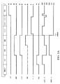
一例として、通気セグメントの開始時に、図2の多段ポンプ100の動作の様々なセグメントに対する弁および分注モータータイミングを示す図3Aを参照すると、遮断弁130が開かれ、通気弁145が開かれている。供給ポンプ150は、圧力を流体に加えて、開いている通気弁145を通して濾過器120から気泡を取り除くように制御される。図3Aに示されているように、バリア弁135は、通気セグメントにおいて開いたままで、通気セグメントの終了時に閉じるものとしてよい。もしそうであれば、濾過器120内の圧力が検出され得る(たとえば、上で説明されているポンプコントローラ20などのコントローラによって)が、それは、圧力センサー112によって測定され得る、分注室185内の圧力が、濾過器120内の圧力の影響を受け得るからである。バリア弁135が閉じられたときに、濾過器120内の圧力は、依然として検出され得るが、それは、圧力センサー114によって測定され得る、供給室155内の圧力が、濾過器120内の圧力の影響を受け得るからである。
By way of example, at the beginning of the vent segment, referring to FIG.3A, which illustrates the valve and dispense motor timing for various segments of operation of the
いくつかの弁は、図3Aにおいて、セグメントの変化時に同時に閉じるものとして図示されているが、弁が閉じるタイミングは、圧力スパイクを低減するためにわずかにずらされ得る(たとえば、100ミリ秒)。たとえば、通気セグメントとパージセグメントとの間で、遮断弁130は、通気弁145が開かれるすぐ前に閉じられ得る。しかしながら、様々な実施形態において他の弁タイミングが利用され得ることに留意されたい。それに加えて、セグメントのいくつかが、一緒に実行され得る(たとえば、充填/分注段は、同時に実行されてもよく、その場合、入口弁および出口弁は両方とも、分注/充填セグメントで開いていてよい)。特定のセグメントは、各サイクルに対して繰り返されなくてもよいことにさらに留意されたい。たとえば、パージおよびスタティックパージセグメントは、すべてのサイクルで実行されなくてもよい。同様に、通気セグメントは、図3Bに例示されているように、すべてのサイクルで実行されなくてもよい。さらに、任意の好適な弁およびモータータイミングが使用され得る。
Although some valves are shown in FIG. 3A as closing at the same time as the segment changes, the timing at which the valves close can be shifted slightly (eg, 100 milliseconds) to reduce pressure spikes. For example, between the vent segment and the purge segment, the
供給ポンプ150は、事前定義済み速度で通気が行われるように制御され、それにより、より長い通気時間およびより低い通気速度を可能にし、それによって、通気の無駄になる量を正確に制御することができる。供給ポンプ150が、空気圧式ポンプである場合、通気流体経路内に流体流の制限が設けられ、供給ポンプ150に加えられる(および圧力センサー114によって測定される)空気圧は、「通気」設定点圧力を維持するために増減され、それにより、他の方法では無制御の方法の何らかの制御が可能になる。
The
図3Aおよび図3Bに例示されているように、空気検出試験は、セグメントにおいて実行され得る(たとえば、以下で説明されているようにパージセグメントの開始時)。たとえば、分注側で空気検出試験を実行するために、バリア弁135、パージ弁140、および出口弁147が閉じられ、それにより分注室185を隔離することができる。分注モーター200は、分注室185を所望の圧力(たとえば、5ポンド/平方インチ(psi))にするように制御される。次いで、分注モーター200が、固定された距離だけ移動され、分注室185内の圧力(P)の変化(デルタ)が、決定される。隔離された分注室185(またはポンプシステムの他の隔離されている部分)の容積の固定された変化に対する圧力変化(デルタP)を決定することによって、分注室185(またはノズルの前の出力弁147または他の弁までの配管を含むポンプシステムの隔離されている部分)における空気の量が決定され得るが、これは、上で参照されている国際公開第2013/028542A2号、名称「SYSTEM AND METHOD FOR DETECTING AIR IN A FLUID」で説明されているとおりである。
As illustrated in FIGS. 3A and 3B, an air detection test may be performed on a segment (eg, at the start of a purge segment as described below). For example, to perform an air detection test on the dispense side, the
圧力センサー114が充填側にあれば、充填側で空気検出試験を実行することも可能である。いくつかの実施形態において、入口弁125および遮断弁130は、供給室155を隔離するために閉じることができる(「隔離部分」と称され得る)。いくつかの実施形態において、入口弁125、通気弁145、およびバリア弁135は、供給室155および濾過器120を隔離するために閉じることができる(一緒に「隔離部分」とも称され得る)。充填モーター175は、隔離部分を所望の圧力(たとえば、5psi)にするように制御される。次いで、充填モーター175が、固定された距離だけ移動され、隔離部分内の圧力(P)の変化(デルタ)が、決定される。隔離部分(またはポンプシステムの他の隔離部分)の容積の固定された変化に対する圧力変化(デルタP)を決定することによって、供給室155(または供給室155と濾過器120)内の空気の量が決定され得る。
If the
いくつかの実施形態において、分注モーター200は、事前定義された圧力変化(たとえば、ポンプシステムへのインターフェースを介してユーザによって定義される)を維持するために制御されることができる。事前定義された圧力変化を達成するために、コントローラは、分注室185内の利用可能な容積の適切な変化を決定し、分注モーター200を制御してピストン192をしかるべく移動させることができる。ここでもまた、この測定量を用いて、分注室185またはノズルの前の出力弁147または他の弁までの配管を含むポンプシステムの他の隔離されている部分における空気の量を決定することができるが、これは、上で参照されている国際公開第2013/028542A2号、名称「SYSTEM AND METHOD FOR DETECTING AIR IN A FLUID」で説明されているとおりである。いくつかの場合において、検出された空気の測定量が、閾値量よりも少ない場合、パージおよび/またはスタティックパージセグメントはスキップされ、それによりサイクル時間を短縮できる。検出された空気の量が、閾値よりも多い場合、警告または是正処置が講じられるものとしてよい。
In some embodiments, dispense
いくつかの場合において、パージセグメントにおいて、遮断弁130が閉じられ、バリア弁135が閉じられ、通気弁145が閉じられ、パージ弁140が開いており、出口弁147が閉じられている。図3Aおよび図3Bに例示されているように、パージ弁140を開く前に遅延があり得、その際に、分注室185は隔離される。分注ポンプ180は、空気検出試験が実行されるように分注室185内の流体に圧力を加えることができる。
In some cases, in the purge segment,
パージセグメントにおいて、パージ弁140が開かれたときに、分注ポンプ180は、分注室185内の流体に圧力を加えて、気泡をパージ弁140に通す。スタティックパージセグメントにおいて、分注ポンプ180は停止されるが、パージ弁140は開いたままであり、空気を放出し続ける。パージまたはスタティックパージセグメントにおいて除去される過剰な流体は、多段ポンプ100から外へ導かれる(たとえば、流体源15、貯蔵タンク118に戻されるか、または破棄される)か、または供給段105にリサイクルされ得る。
In the purge segment, when the
いくつかの場合において、図3Aおよび図3Bに例示されているように、すべての弁は、準備完了セグメントにおいて閉じられ得る。いくつかの場合において、供給ポンプ150が流体源(たとえば、ソースボトルまたは貯蔵タンク)の周囲圧力に到達できるように、遮断弁130およびバリア弁135が開かれ、パージ弁140が閉じられ得る。
In some cases, as illustrated in FIGS. 3A and 3B, all valves may be closed in the ready segment. In some cases,
分注セグメントにおいて、出口弁147が開き、分注ポンプ180が分注室185内の流体に圧力を加える。出口弁147は、分注ポンプ180よりも遅くコントロールに反応し得るので、出口弁147が最初に開かれ、所定の期間が経過した後分注モーター200が始動され得る。これは、分注ポンプ180が部分的に開いた出口弁147に流体を押し通すのを防ぐ。さらに、これは、流体が分注ノズルを上って行くことが弁開放によって引き起こされ、その後前進流体運動がモーターの作用によって引き起こされるのを防ぐ。いくつかの場合において、出口弁147が開かれ、分注ポンプ180が同時に分注し始め得る。
In the dispense segment,
他のセグメントも実行され得る。たとえば、サックバック(suckback)セグメントが実行され、それにより分注ノズル内の過剰な流体を取り除くことができる。サックバックセグメントにおいて、出口弁147は閉じて、二次モーターまたは真空が、出口ノズルから過剰な流体を吸い出すために使用され得る。代替的に、出口弁147は開いたままとなり、分注モーター200は逆転されて、流体を分注室185内に引き戻すことができる。サックバックセグメントは、過剰な流体のウェハ25上への滴りを防ぐのに役立ち得る。
Other segments may be performed. For example, a suckback segment may be performed, thereby removing excess fluid in the dispense nozzle. In the suckback segment,
様々な弁の開閉が、流体中に圧力スパイクを引き起こす可能性がある。たとえば、スタティックパージセグメントの終了時にパージ弁140が閉じると、分注室185内に圧力増大が引き起こされ得る。これは、各弁が閉じるときに少量の流体を押しのけ得るので生じる可能性がある。たとえば、パージ弁140は閉じるときに少量の流体を分注室185内に押しのけ得る。出口弁147は、パージ弁140が閉じることにより圧力増大が生じたときに閉じられるので、ウェハ上への流体の「吐出」は、圧力が低下しない場合にその後の分注セグメントにおいて生じ得る。スタティックパージセグメント、または追加のセグメントにおいてこの圧力を解放するために、分注モーター200は逆転されて、ピストン192を所定の距離だけ後退させ、バリア弁135および/またはパージ140が閉じることによって引き起こされる圧力上昇を補償することができる。
The opening and closing of various valves can cause pressure spikes in the fluid. For example, closing the
準備完了セグメントにおいて、分注室185内の圧力は、ダイアフラムの特性、温度、または他の要因に基づき変化し得ることに留意されたい。分注モーター200は、この圧力ドリフトを補償するように制御され得る。
Note that in the ready segment, the pressure in dispense
分注ポンプおよび供給ポンプのところの圧力センサーからのリアルタイムフィードバックに基づき分注側さらには充填側でのポンプ動作を制御することによって、本明細書で開示されている多段ポンプの実施形態は、穏やかな流体処理特性を提供し、潜在的にダメージを引き起こしそうな圧力スパイクを回避することができる。上で説明されているように、様々なポンプ制御メカニズムおよび弁タイミングが、プロセス流体に対する圧力の悪影響を低減するのにさらに役立ち得る。たとえば、トラップされた空間上で弁を閉じる動作を減らすように弁およびモータータイミングが選択され得る。 By controlling pumping on the dispense side and also on the fill side based on real-time feedback from pressure sensors at the dispense pump and the supply pump, the multi-stage pump embodiments disclosed herein provide a gentler It provides excellent fluid handling properties and avoids potentially damaging pressure spikes. As described above, various pump control mechanisms and valve timing may further help reduce the adverse effects of pressure on the process fluid. For example, valve and motor timing may be selected to reduce valve closing on the trapped space.
図4は、準備完了、分注、濾過、通気、パージ、空気検出、および充填セグメントを含む分注サイクルにおいて収集された一組の監視データ(たとえば、図1を参照しつつ上で説明されているポンプシステム10などのポンプシステムの制御ロジックによって監視される)を表示するグラフィカルユーザインターフェース(GUI)400の図表現である。監視データは、分注サイクルが完了する前、その間、および/または完了した後に、リアルタイムで表示され得る。GUI400は、ポンプコントローラ(たとえば、図1を参照しつつ上で説明されているポンプコントローラ20)またはポンプコントローラから受信されたデータに基づく別のコンピューティングデバイスによって提供され得る。例示されている実施形態において、監視データは、分注圧力410(たとえば、図2Aまたは図2Bの圧力センサー112から決定されるような)、充填圧力420(たとえば、図2Aまたは図2Bの圧力センサー114によって決定されるような)、分注モーター位置430(図4では分注位置と称され、ミリメートルの排水量単位で表されている)、および供給モーター位置440(図4では充填位置と称され、ミリメートルの排水量単位で表されている)を含む。データセットのうちの1つまたは複数はベースライン(基準サイクル)と比較されて、ポンプの動作を制御し、エラーを判定し、分注が「良好な」分注であったかを決定する、などを行うことができる。
FIG. 4 shows a set of monitoring data collected during a dispense cycle that includes a ready, dispense, filter, vent, purge, air detect, and fill segment (e.g., as described above with reference to FIG. 1). FIG. 1 is a graphical representation of a graphical user interface (GUI) 400 that displays (monitored by the control logic of a pump system, such as pump system 10). The monitoring data may be displayed in real time before, during, and / or after the dispense cycle is completed.
より具体的には、ベースラインプロファイルは、1つまたは複数のパラメータについて確定され得る。一例として、図1を参照すると、ポンプ100の動作中に、これらのパラメータは、各パラメータについて動作プロファイルを作成するために測定され得る。次いで、各パラメータに対するベースラインプロファイルは、1つまたは複数のパラメータに対する1つまたは複数の対応する地点または部分における動作プロファイルと比較され得る。アラーム条件は、動作プロファイルがベースラインプロファイルからある特定の許容範囲を超えて異なる場合に存在し得る。そうでなければ、ポンプ100は、動作を続けることができる。
More specifically, a baseline profile may be determined for one or more parameters. By way of example, referring to FIG. 1, during operation of
いくつかのパラメータに関するベースラインプロファイルを確定するために、パラメータは、ベースライン(基準)または「黄金律」試行時に測定され得る。一実施形態において、ポンプ100の操作者またはユーザは、ポンプ100の通常使用または動作中にポンプ100が利用される条件および機器に実質的に類似するか、または同一である液体、条件、および機器を使用してその仕様に合わせてポンプ100を設定することができる。次いで、ポンプ100は、分注サイクルでユーザのレシピに従って流体を分注するように操作され得る。この分注サイクルにおいて、パラメータは、実質的に連続的に、または一組の地点で測定され、それによりそのパラメータに対する動作プロファイルを作成することができる。特定の一実施形態において、パラメータのサンプリングは、約1ミリ秒から10ミリ秒の間隔で行われ得る。
To establish a baseline profile for some parameters, the parameters may be measured during a baseline (baseline) or “golden rule” trial. In one embodiment, the operator or user of the
ユーザは、この分注サイクルでGUI400を介してポンプ100の動作パラメータを確認することができる。この分注サイクルにおいてポンプ100によって行われる分注は、無欠陥ウェハまたは製品が生産されるように許容範囲または仕様の範囲内にあるべきである。ユーザが、ポンプ動作および分注品質の両方に満足している場合、ユーザは、動作プロファイル(たとえば、分注サイクルで取られたパラメータに対する測定)は、ポンプ100によるその後の分注動作に対するパラメータのベースラインプロファイルとして記憶され、利用されるべきであることが所望されることを、ポンプコントローラを通して示すことができる。この方式で、ポンプ100に対して、1つまたは複数のポンプ動作パラメータに対するベースラインプロファイルが確定され得る。
The user can check the operating parameters of the
次いで、ポンプ100の動作中に生じている可能性のある様々な問題を検出するために、ポンプ100の動作時に作成されたパラメータに対する動作プロファイルが同じパラメータに対応するベースラインプロファイルと比較され得る。これらの比較は、ポンプコントローラ20、管理ステーション、またはポンプコントローラ20もしくは他のコンピューティングデバイスと通信する他のコンピューティングデバイスによって行われるものとしてよく、様々な形態を取り得る。たとえば、ベースラインプロファイルの1つまたは複数の点におけるパラメータの値は、動作プロファイルにおける実質的に等価な点におけるパラメータの値と比較されてよく、ベースラインプロファイルの平均値は、動作プロファイルの平均値と比較されてよく、ベースラインプロファイルの一部におけるパラメータの平均値は、動作プロファイルにおける実質的に同じ点におけるパラメータの平均値と比較されてよく、などとなる。
An operating profile for the parameters created during operation of the
説明されている比較のタイプは、例にすぎないこと、およびベースラインプロファイルと動作プロファイルとの間の好適な比較が利用され得ることは理解されるであろう。実際に、多くの場合において、複数の比較、または比較のタイプが、特定の問題または条件が生じているかどうかを決定するために利用され得る。また、利用される比較のタイプは、少なくとも一部は、検出されようとする条件に依存し得ることも理解されるであろう。同様に、比較される動作およびベースラインプロファイルの点または部分は、他にも要因はあるがとりわけ、検出されようとしている条件にも依存し得る。それに加えて、利用される比較は、特定の分注サイクルの間、または特定の分注サイクルの完了後にポンプの動作中に実質的にリアルタイムで行われ得ることが理解されるであろう。 It will be appreciated that the type of comparison described is only an example, and that a suitable comparison between the baseline profile and the operating profile may be utilized. In fact, in many cases, multiple comparisons, or types of comparisons, may be utilized to determine whether a particular problem or condition has occurred. It will also be appreciated that the type of comparison utilized may depend, at least in part, on the condition to be detected. Similarly, the points or portions of the operations and baseline profiles that are compared may depend on the conditions that are to be detected, among other factors. In addition, it will be appreciated that the comparison utilized may be performed substantially in real time during operation of the pump during a particular dispense cycle or after completion of a particular dispense cycle.
比較の結果、差がある特定の許容範囲を外れる場合、アラームがポンプコントローラ20に登録され得る。このアラームは、ポンプコントローラ20によって指示され得るか、またはアラームは、ポンプコントローラ20とインターフェースするツールコントローラ(たとえば、ポンプトラック)に送信され得る。上で説明されている比較のタイプと同様に、与えられた比較で利用される特定の許容範囲は、広範な要因、たとえば、比較が行われるプロファイルの点もしくは部分、ユーザがポンプ100を使用する際のプロセスもしくはレシピ、ポンプ100によって分注されている流体のタイプ、利用されているパラメータ、検出することが望まれている条件もしくは問題、許容範囲のユーザの望みもしくはユーザチューニングなどに依存し得る。たとえば、許容範囲は、ベースラインプロファイルの比較点におけるパラメータの値のパーセンテージ、または設定数であってよく、許容範囲は、ベースラインプロファイルを比較の点(または部分)に応じて動作プロファイルと比較したときに異なっていてよく、比較点における動作プロファイルの値が、ベースラインプロファイルの比較点におけるパラメータの値よりも低い場合にそれがその値よりも高い場合と異なる許容範囲があり得る、などである。
If the comparison results in a difference outside a certain tolerance, an alarm may be registered with the
ベースラインプロファイルに対するデータは、ベースラインプロファイルを確定するために使用されるポンプの稼働時にサンプリングされたデータの全部または一部を含み得る。たとえば、ポンプの圧力サンプリングが1ミリ秒ごとである場合、ベースラインプロファイルは、必要な記憶容量を低減するために20ミリ秒ごとにサンプリングされた測定結果を含むものとしてよい。ポンプ100の動作中に、パラメータは、パラメータに対する動作プロファイルを作成するために測定され得る。ここでもまた、動作プロファイルに対するデータは、動作に対するそのパラメータのサンプリングされたデータの全部またはその何らかのサブセットを表し得る(たとえば、5ミリ秒ごとまたは他の時間的周期で収集されるデータ)。次いで、一実施形態により、分注サイクル、特定のセグメント、セグメントの組合せ、またはサイクルもしくはセグメントの一部に対する適合度測定量が、ベースラインプロファイルを使用して動作プロファイルについて決定され得る。たとえば、対応するベースラインプロファイルデータを使用して5ミリ秒ごとに収集された動作プロファイルデータについてR 2乗測定量(すなわち、決定の係数、これは動作プロファイルデータがベースラインプロファイルデータとどれだけよく適合するかを示す数である)が決定され得る。適合度測定量が、許容可能範囲を外れている場合、アラーム条件が存在し得る。
The data for the baseline profile may include all or some of the data sampled during operation of the pump used to establish the baseline profile. For example, if the pressure sampling of the pump is every 1 millisecond, the baseline profile may include measurements that are sampled every 20 milliseconds to reduce the required storage capacity. During operation of the
上記の例において、5ミリ秒ごとに記憶されたデータは、適合度を試験するために使用され、その一方で、ポンプはより速い速度で(たとえば、1ミリ秒ごとに)パラメータをサンプリングし得る。異なる速度で、すなわち、1ミリ秒ごとに、または30ミリ秒ごとに記憶されるデータが使用され得るが、記憶されているサンプルの間の時間が少なくなるにつれ、メモリ使用量が上昇し、時間が多くなるにつれ適合度測定量の精度は減少し得る。したがって、適合度測定量に対してデータが記憶される頻度は、データ記憶装置能力と適合度測定量の精度とのバランスをとるように選択され得る。さらに、R 2乗測定量は、上記の例では適合度測定量として使用されているが、他の適合測定量も使用され得る。 In the above example, data stored every 5 ms is used to test for goodness of fit, while the pump may sample parameters at a faster rate (e.g., every 1 ms) . Data stored at different rates, i.e. every 1 ms or every 30 ms, may be used, but as the time between stored samples decreases, the memory usage increases and the time The accuracy of the goodness-of-fit measure may decrease as the number increases. Thus, the frequency at which data is stored for the fitness measure may be selected to balance data storage capacity with the accuracy of the fitness measure. Further, the R-squared measure is used as a goodness-of-fit measure in the above example, but other fit measures may be used.
図5Aおよび図5Bは、例示的な一組の監視データを表示するグラフィカルユーザインターフェース500の一実施形態の図表現である。図5Aおよび図5Bにおいて例示されているように、ポンプ(たとえば、図2Aを参照しつつ上で説明されている多段ポンプ100)の動作サイクルに対するデータは、カラム510に表示され、基準(ベースライン)サイクルに対するデータは、カラム520に表示される。試験値(すなわち、警告またはエラー限界と突き合わせて試験された値)は、カラム530に載っている。それに加えて、ユーザ指定警告およびエラー限界は、カラム540および550に表示されている。適用される試験(より大きい、より小さい、など)が、カラム545に表示される。カラム560において、ユーザは、試験値がエラー試験に通らなかったときのアラームタイプを選択することができる。いくつかの実施形態において、アラームタイプは4つあり、それぞれ、情報アラーム、警告アラーム、エラーアラーム(システムは、可能な限り最良の形で現在のサイクルを完了するが、別のサイクルが開始するのを許さない)、および重大アラーム(システムは、現在のサイクルをシャットダウンし、ポンプを停止する)である。
5A and 5B are graphical representations of one embodiment of a
一例において、警告は、警告処置が講じられることを意味し得るが、エラーは、エラー処置が講じられることを意味し得る。警告およびエラー処置は、いくつかの実施形態においてユーザ構成可能であるものとしてよい。たとえば、限定はしないが、警告処置は、動作を停止することなく警告条件が生じたことを示す通知をユーザに送信するステップを含み得るが、エラー処置は、通知を送信するステップと、さらなる動作が行われるのを防ぐステップ(またはポンプの次のサイクルを防ぐステップ)を含み得る。このようにして、ポンプシステムは、ポンプトラックが加工のために別のウェハを不必要に送らないように適切な限り頻繁にまた早期にその動作条件をポンプトラックに伝達することができる。 In one example, a warning may mean that an alert action is taken, while an error may mean that an error action is taken. Warning and error actions may be user-configurable in some embodiments. For example, but not by way of limitation, the alert action may include sending a notification to the user indicating that the alert condition has occurred without halting the operation, but the error action may include sending the notification and further action. (Or preventing the next cycle of the pump). In this way, the pump system can communicate its operating conditions to the pump truck as often and as early as appropriate so that the pump truck does not unnecessarily send another wafer for processing.
たとえば、限定はしないが、次の比較がGUI500に例示されている。
For example, without limitation, the following comparison is illustrated in
準備完了 - 準備完了圧力(ポンド/平方インチ(PSI)):分注セグメントまたは空気検出試験の開始時に室(たとえば、分注室)を加圧するシステム設定。このポンプ動作パラメータは、約3psi以下(たとえば、約1psi)に設定され得る。いくつかの場合において、準備完了圧力を約3psiに設定することで、分注室にバックラッシュが生じるのを防ぐことができる。当業者であれば、準備完了圧力を0psiまたは陰圧に設定することも、いくつかの用途では有利である得ることを理解するであろう。 Ready-Ready Pressure (Pounds per Square Inch (PSI)): A system setting that pressurizes a chamber (eg, dispense chamber) at the start of a dispense segment or air detection test. This pump operating parameter may be set to about 3 psi or less (eg, about 1 psi). In some cases, setting the ready pressure to about 3 psi can prevent backlash in the dispense chamber. One skilled in the art will appreciate that setting the ready pressure to 0 psi or negative pressure may also be advantageous for some applications.
分注 - 圧力プロファイル比較(%):「分注確認」とも称される、ベースライン分注圧力プロファイル(たとえば、サイクル985)と比較された注目するサイクル(たとえば、サイクル989)の分注セグメントに対する分注圧力プロファイルの適合度。上で説明されているように、一実施形態において、これは、5ミリ秒ごとに収集された動作プロファイルデータを対応するベースラインプロファイルデータと比較することによって決定され得るR 2乗測定量を使用して行われ得る。適合度値は試験値として働き、適合度警告またはエラー閾値と比較される。この例では、注目するサイクルの適合度が85未満の場合、警告が生成されるものとしてよく、適合度が80未満の場合、エラーが発生し得る。しかしながら、「警告」がアラームタイプで選択されるので、適合度値がエラー閾値未満になる場合であっても警告は生成される。充填圧力、モーター位置、または他のパラメータの適合度も、評価され得る。パラメータの適合度は、サイクルに対して全体として、他のセグメントに対して、セグメントの組合せに対して、サイクルの他の部分に対して評価され得る。警告またはエラーは、分注室内の空気、出口弁タイミングの変化、ポンプの機械的問題、または他の課題を指示し得る。 Dispense-Pressure Profile Comparison (%): For the dispense segment of the cycle of interest (e.g., cycle 989) compared to the baseline dispense pressure profile (e.g., cycle 985), also referred to as "dispense confirmation" Dispensing pressure profile fit. As described above, in one embodiment, this uses an R-squared measure that can be determined by comparing the motion profile data collected every 5 ms to the corresponding baseline profile data. Can be done. The goodness-of-fit value serves as a test value and is compared to a goodness-of-fit warning or error threshold. In this example, if the fitness of the cycle of interest is less than 85, a warning may be generated, and if the fitness is less than 80, an error may occur. However, since "Warning" is selected for the alarm type, a warning is generated even if the fitness value falls below the error threshold. Goodness of filling pressure, motor position, or other parameters may also be evaluated. The fit of the parameters may be evaluated for the cycle as a whole, for other segments, for segment combinations, and for other parts of the cycle. Warnings or errors may indicate air in the dispense chamber, changes in outlet valve timing, mechanical problems with the pump, or other issues.
分注 - 最大圧力(PSI):分注セグメントにおいて分注室に発生する最大圧力。試験値は、注目するサイクルの最大分注圧力と基準サイクルとの差または比較であるものとしてよい。類似の試験は、他のセグメント、もしくはセグメントの組合せにおける最大、最小、平均などの分注圧力、またはセグメントもしくはセグメントの組合せにおける最大、最小、平均などの充填(上流)圧力について実行され得る。エラーまたは警告は、出口弁タイミングの変化、出口ライン内の閉塞、分注室内の空気、出口弁が開かないこと、ポンプの機械的問題、または他の課題を指示し得る。 Dispensing-Maximum Pressure (PSI): The maximum pressure generated in the dispensing chamber in the dispensing segment. The test value may be the difference or comparison between the maximum dispense pressure of the cycle of interest and the reference cycle. Similar tests may be performed for dispense pressures such as maximum, minimum, average, etc. in other segments or combinations of segments, or for fill (upstream) pressures, such as maximum, minimum, averages, etc., in segments or combinations of segments. The error or warning may indicate a change in outlet valve timing, a blockage in the outlet line, air in the dispense chamber, the outlet valve not opening, a mechanical problem with the pump, or other issues.
分注 - 平均圧力(PSI):分注サイクルにおける平均圧力。試験値は、注目するサイクルと基準サイクルとの間の平均分注圧力の差または比較であるものとしてよい。類似の試験は、他のセグメント、もしくはセグメントの組合せにおける最大、最小、平均などの分注圧力、またはセグメントもしくはセグメントの組合せにおける最大、最小、平均などの充填圧力について実行され得る。エラーまたは警告は、プロセス流体粘度の変化、出口弁が開かないこと、または他の課題を指示し得る。 Dispense-Average Pressure (PSI): The average pressure in the dispense cycle. The test value may be the difference or comparison of the average dispense pressure between the cycle of interest and the reference cycle. Similar tests may be performed for dispense pressures, such as maximum, minimum, average, or the like, for other segments or combinations of segments, or for filling pressures, such as maximum, minimum, average, for a segment or combination of segments. An error or warning may indicate a change in process fluid viscosity, an outlet valve not opening, or other problem.
分注 - カットオフ圧力(PSI):流体流がノズルのところで遮断されたときの分注室で測定された圧力。一例として、分注が終了してから250マイクロ秒(ms)経過すると、カットオフ圧力は、次の100msにわたって分注室で測定された平均圧力である。一般的に、カットオフ圧力は、出口弁が閉じたときの分注圧力におけるわずかな平準化として目立つものである(たとえば、図4参照)。カットオフ圧力は、弁のわずかなタイミングおよびモータータイミングに応じて変化する。試験値は、注目するサイクルおよび基準サイクルにおけるカットオフ圧力の間の差であるものとしてよい。エラーまたは警告は、出口弁閉鎖タイミングの変化、ポンプの機械的問題、または他の課題を指示し得る。 Dispense-Cutoff Pressure (PSI): The pressure measured in the dispense chamber when fluid flow is shut off at the nozzle. As an example, after 250 microseconds (ms) have elapsed since the end of the dispense, the cutoff pressure is the average pressure measured in the dispense chamber over the next 100 ms. In general, the cutoff pressure is noticeable as a slight leveling in dispense pressure when the outlet valve is closed (see, eg, FIG. 4). The cut-off pressure varies depending on slight valve timing and motor timing. The test value may be the difference between the cutoff pressure in the cycle of interest and the reference cycle. The error or warning may indicate a change in outlet valve closure timing, a mechanical problem with the pump, or other problem.
分注 - 平均モーター速度(ミリリットル/秒(mL/秒)):分注セグメントにおける分注モーターの平均モーター速度。試験値は、注目するサイクルおよび基準サイクルの分注セグメントにおける平均モーター速度の間の差または比較であるものとしてよい。類似の試験は、他のセグメント、もしくはセグメントの組合せにおける分注モーター速度の平均、最大、最小、または他の測定量、またはセグメントもしくはセグメントの組合せにおける供給モーター速度の平均、最大、最小、または他の測定量について実行され得る。エラーまたは警告は、レシピの変更もしくは他の課題を指示し得る。 Dispense-Average Motor Speed (mL / s): The average motor speed of the dispense motor in the dispense segment. The test value may be the difference or comparison between the average motor speed in the dispense segment of the cycle of interest and the reference cycle. A similar test is the average, maximum, minimum, or other measurand of dispense motor speed in another segment or combination of segments, or the average, maximum, minimum, or other of the supply motor speed in a segment or combination of segments. May be performed for An error or warning may indicate a change in the recipe or other task.
分注 - 全モーター容積(ミリリットル(mL)):分注セグメントにおいて移動した分注モーターの量。試験値は、注目するサイクルおよび基準サイクルの分注セグメントにおいて移動した分注モーターの量の間の差または比較であるものとしてよい。類似の試験は、他のセグメント、もしくはセグメントの組合せにおける分注モーター移動、またはセグメントもしくはセグメントの組合せにおける供給モーターの移動について実行され得る。エラーまたは警告は、レシピの変更もしくは他の課題を指示し得る。 Dispense-Total Motor Volume (milliliter (mL)): The amount of dispensed motor moved in the dispense segment. The test value may be the difference or comparison between the amount of dispense motor moved in the dispense segment of the cycle of interest and the reference cycle. Similar tests may be performed for dispense motor movement in other segments or segment combinations, or for feed motor movement in segments or segment combinations. An error or warning may indicate a change in the recipe or other task.
分注 - 空気検出容積(mL):室(たとえば、分注側の分注室)内の圧力の所定の変化を引き起こすようにモーターが移動した量を決定する。上で参照されている国際公開第2013/028542A2号、名称「SYSTEM AND METHOD FOR DETECTING AIR IN A FLUID」において説明されているように、そのような試験は、分注室、または分注ノズルに至るライン内に空気があるか決定するために使用され得る。試験値は、注目するサイクルおよび基準サイクルに対する空気検出試験において検出された空気の量の間の差または比較であるものとしてよい。出力弁は、配管を通してポンプからある距離のところに配置され得るので、空気検出試験は、分注ライン内の気泡もしくは空気、漏れ、または他の課題を識別するのに役立ち得る。そのようなものとして、空気検出は、分注確認から何が欠落しているかを検出することができるので重要であり得る(たとえば、空気検出は、R 2乗測定量または適合度測定量が検出できない空気および/または問題を検出することができる)。一実施形態において、この空気検出試験の品質は、分注開始時のバックラッシュを解消するか、または軽減するピストン上に取り付けられたバックラッシュ防止メカニズムでさらに高められ得る。好適なバックラッシュメカニズムは、上で参照されている2014年5月28日に出願した米国仮出願第62/004,117号、および2015年5月28日に出願した国際出願第PCT/US2015/2XXXX号、名称「ANTI-BACKLASH MECHANISM FOR MOTOR-DRIVEN COMPONENTS IN PRECISION SYSTEMS AND APPLICATIONS」に記載されており、両方とも参照により本明細書に完全に組み込まれている。空気検出は、ピストンの移動によって駆動されるので、ピストンの移動によって引き起こされるバックラッシュの解消/軽減は、試験値は、何らかのバックラッシュによる影響を受ける可能性があるというのではなく、検出された空気の量をより正確に反映することになることを意味する。 Dispense-Air Detection Volume (mL): Determines the amount the motor has moved to cause a predetermined change in pressure in the chamber (eg, the dispensing chamber on the dispensing side). As described in the above referenced WO 2013 / 028542A2, entitled "SYSTEM AND METHOD FOR DETECTING AIR IN A FLUID", such testing may lead to a dispensing chamber or dispensing nozzle. It can be used to determine if there is air in the line. The test value may be the difference or comparison between the amount of air detected in the air detection test relative to the cycle of interest and the reference cycle. Since the output valve may be located some distance from the pump through the tubing, the air detection test may help identify bubbles or air in the dispense line, leaks, or other issues. As such, air detection can be important because it can detect what is missing from the dispense confirmation (e.g., air detection requires an R-squared or fitness measure) to be detected. Inability to detect air and / or problems). In one embodiment, the quality of this air detection test can be further enhanced with a backlash prevention mechanism mounted on the piston that eliminates or mitigates backlash at the start of dispense. Suitable backlash mechanisms are described above in U.S. Provisional Application No. 62 / 004,117 filed May 28, 2014, and International Application No.PCT / US2015 / 2XXXX filed May 28, 2015. And the name "ANTI-BACKLASH MECHANISM FOR MOTOR-DRIVEN COMPONENTS IN PRECISION SYSTEMS AND APPLICATIONS", both of which are fully incorporated herein by reference. Since the air detection is driven by the movement of the piston, the elimination / mitigation of the backlash caused by the movement of the piston was detected, rather than the test value could be affected by any backlash. This means that the air volume will be more accurately reflected.
充填 - 最小充填圧力(PSI):充填セグメントにおいて供給室内に発生する最小圧力。試験値は、注目するサイクルおよび基準サイクルの充填セグメントの最小充填圧力の間の差または比較であるものとしてよい。注目するサイクルと基準サイクルとの間の最小充填圧力の相違または差は、ライン内に詰まりが生じていること、またはたとえば、流体を引き込むより大きい真空(陰圧)をかけるポンプによって克服され得る他の問題があることを指示し得る。相違または差は、ポンプに機械的問題があること、粘度変化、または他の課題も指示し得る。類似の試験は、他のセグメント、もしくはセグメントの組合せにおける最大、最小、平均などの充填圧力、またはセグメントもしくはセグメントの組合せにおける最大、最小、平均などの分注圧力について実行され得る。 Filling-Minimum filling pressure (PSI): The minimum pressure generated in the supply chamber in the filling segment. The test value may be the difference or comparison between the minimum filling pressure of the filling segment of the cycle of interest and the reference cycle. Differences or differences in the minimum fill pressure between the cycle of interest and the reference cycle may be due to clogging in the line or other pump that may be overcome, for example, by applying a larger vacuum (negative pressure) to draw fluid. May indicate that there is a problem. Differences or differences may also indicate a mechanical problem with the pump, a change in viscosity, or other issues. Similar tests may be performed for filling pressures, such as maximum, minimum, average, etc. in other segments or combinations of segments, or dispense pressures, such as maximum, minimum, averages, in segments or combinations of segments.
濾過 - 圧力プロファイル比較(%):「濾過確認」とも称される、ベースライン充填圧力プロファイル(たとえば、サイクル985)と比較された注目するサイクル(たとえば、サイクル989)の濾過セグメントに対する充填圧力プロファイルの適合度。適合度値(たとえば、R 2乗測定量)は試験値として働き、適合度警告またはエラー閾値と比較される。この例では、注目するサイクルの適合度測定量が85%(または他の何らかの測定量)未満の場合、警告が生成されるものとしてよく、適合度測定量が80%未満の場合、エラーが発生し得る。しかしながら、「警告」がアラームタイプで選択されるので、適合度値がエラー閾値未満になる場合であっても警告は生成される。充填圧力プロファイルは、他のセグメント、セグメントの組合せ、または全体としてサイクルについて同様に評価され得る。ここでもまた、これは、供給段における流体圧力が現在検出され得るので可能である(たとえば、図2Aおよび図2Bを参照しつつ上で説明されている圧力センサー114を介して)。エラーまたは警告は、充填室内の空気、分注室内の空気、入口ライン内の閉塞、粘度変化、ポンプの機械的問題、または他の課題を指示し得る。
Filtration-Pressure Profile Comparison (%): The fill pressure profile for the filtration segment of the cycle of interest (e.g., cycle 989) compared to the baseline fill pressure profile (e.g., cycle 985), also referred to as "filtration confirmation" Goodness of fit. The goodness-of-fit value (eg, R squared measure) serves as a test value and is compared to a goodness-of-fit warning or error threshold. In this example, a warning may be generated if the fitness measure for the cycle of interest is less than 85% (or some other measure), and an error will occur if the fitness measure is less than 80%. I can do it. However, since "Warning" is selected for the alarm type, a warning is generated even if the fitness value falls below the error threshold. The fill pressure profile can be similarly evaluated for other segments, combinations of segments, or cycles as a whole. Again, this is possible because the fluid pressure in the supply stage can now be detected (eg, via the
濾過 - 平均デルタ圧力(PSI):下流(分注)側と上流(充填)側との間の圧力の差。当業者であれば、圧力降下(すなわち、流体搬送ネットワークの2点の間の圧力の差)は、流れに対する抵抗によって引き起こされる、摩擦力が、管内を流れるときに流体に作用するときに生じ得ることを理解するであろう。したがって、充填側の圧力センサー(たとえば、図2Aおよび図2Bを参照しつつ上で説明されている圧力センサー114)によって測定された圧力が、許容可能範囲または限度(たとえば、1psi)を外れて上昇または降下した場合に、何かが悪いという指示、たとえば、空気の殺到、通気されなかった濾過膜の内側に閉じ込められた空気、時間の経過とともに蓄積した微粒子による濾過器の詰まりであり得るか、または濾過器それ自体に不都合がある、または他の何らかの事象が生じている(たとえば、濾過器の変更、裂けて開いたまたは徐々に劣化したことで生じる濾過膜の漏れなど)という指示であり得る。
Filtration-Mean Delta Pressure (PSI): The difference in pressure between the downstream (dispensing) side and the upstream (filling) side. One skilled in the art will recognize that a pressure drop (i.e., a pressure difference between two points in a fluid transport network) can occur when a frictional force, acting on the fluid as it flows through a tube, is caused by resistance to flow. You will understand that. Thus, the pressure measured by the fill-side pressure sensor (e.g.,
濾過 - 最大上流圧力(PSI):濾過セグメントにおいて供給室内に発生する最大圧力。試験値は、注目するサイクルおよび基準サイクルの濾過セグメントの最大充填圧力の間の差または比較であるものとしてよい。類似の試験は、他のセグメント、もしくはセグメントの組合せにおける最大、最小、平均などの上流圧力、またはセグメントもしくはセグメントの組合せにおける最大、最小、平均などの分注圧力について実行され得る。エラーまたは警告は、濾過器の詰まり、粘度の変化、ポンプの機械的問題、または他の課題を指示し得る。 Filtration-Maximum Upstream Pressure (PSI): The maximum pressure generated in the feed chamber in the filtration segment. The test value may be the difference or comparison between the maximum fill pressure of the filtration segment of the cycle of interest and the reference cycle. Similar tests may be performed for upstream pressures, such as maximum, minimum, average, etc. in other segments or combinations of segments, or dispense pressures, such as maximum, minimum, averages, in segments or combinations of segments. An error or warning may indicate a filter clog, a change in viscosity, a mechanical problem with the pump, or other problem.
充填 - 平均モーター速度(ミリリットル/秒(mL/秒)):充填制御に対するユーザ構成可能パラメータ。たとえば、ユーザは、充填圧力(たとえば、図2Aおよび図2Bを参照しつつ上で説明されている圧力センサー114によって測定されるような)が限度または閾値(すなわち、最小充填圧力)よりも低くなるべきでないことを指定することができる。一例として、最小充填圧力が、-4psiに設定され、充填圧力が-4psiに達した場合(たとえば、加工しているときのプロセス流体の粘度の変化により)、ポンプシステムは、平均モーター速度を変更して、充填圧力を最小充填圧力以上に維持することができる。このパラメータは、ポンプシステムがモーター速度を変更することができる限度をユーザが指定することを可能にする。たとえば、ポンプシステムがモーターを1mL/秒で始動すると仮定すると、充填圧力は、-2psiに設定され、充填速度は、1mL/秒に設定される。充填セグメントにおいて充填圧力を-2psi以上に維持するために、ポンプシステムは、平均モーター速度限度をチェックし、動作をシャットダウンすることなくモーター速度を.5mL秒に変更する。この例が示しているように、ポンプシステムは、モーター速度(平均モーター速度限度によって制約されているような)を変更し、サイクルをそのまま稼働している間に変更に関するアラームを送出することを許される。これは、ポンプシステムが充填課題を早期に検出し、充填圧力をしかるべく制御し(たとえば、モーター速度を下げることによって)、適切なアラームを送出することを可能にする。そのようなアラームに応答して、操作者は、より多くのウェハの稼働を停止するか、または現在の動作プロファイルを受け入れて、それで稼働することを決定し得る。当業者であれば、圧力が維持されているときに、粘度の変化がモーター速度によって正確に反映され得ることを理解するであろう。したがって、操作者は、現在の充填圧力プロファイル(たとえば、-2psi充填圧力)を新しい基準プロファイルとして保存し、ポンプシステムが.5mL/秒のモーター速度を維持することを許すことを決定し得る。
Fill-Average Motor Speed (milliliter / second (mL / second)): User configurable parameter for filling control. For example, the user may find that the fill pressure (e.g., as measured by
充填 - 全時間(秒):充填セグメントに対する全時間。これは、平均モーター速度に逆相関する。モーター速度が低下した場合、充填セグメントを完了するのに必要な全時間は長くなる。上で説明されている平均モーター速度パラメータと同様に、このパラメータも、充填圧力を監視するために使用され得る。いくつかの場合において、充填圧力が維持され/制御されている限り、ポンプシステムは動作し続け得る。しかしながら、ポンプシステムは、ポンプトラックにアラームを送信し、全時間が事前定義済み閾値を超えたときに動作を無効化し得る。 Fill-Total Time (sec): Total time for the fill segment. This is inversely related to average motor speed. If the motor speed decreases, the total time required to complete the fill segment will increase. Like the average motor speed parameter described above, this parameter can also be used to monitor fill pressure. In some cases, the pump system may continue to operate as long as the fill pressure is maintained / controlled. However, the pump system may send an alarm to the pump truck and disable operation when the total time exceeds a predefined threshold.
サイクル - 全時間(秒):分注サイクルに対する全時間。充填または濾過セグメントに対する時間は変化し、したがって、全サイクルに対する時間も変化し得る。このパラメータは、他の方法では見過ごされる可能性のある課題を検出するのに役立ち得る。たとえば、サイクル内の各個別のセグメントは、許容可能な許容範囲内で動作し得る。そのようなものとして、アラームは発生しなかった。しかしながら、全サイクル時間は、ウェハ加工時間を超えている。これは、1つまたは複数のセグメントが許容可能な許容範囲のマージンが小さくなるように調整される必要があり得ることを示している。 Cycle-Total Time (seconds): The total time for the dispense cycle. The time for the filling or filtration segment will change, and therefore the time for the entire cycle may also change. This parameter can help detect issues that might otherwise be overlooked. For example, each individual segment in a cycle may operate within acceptable tolerances. As such, no alarm was triggered. However, the total cycle time exceeds the wafer processing time. This indicates that one or more segments may need to be adjusted to reduce the margin of acceptable tolerance.
他の試験も実行され得る。たとえば、限定はしないが、試験は、変数としての下流の流量センサーからの出力または分注確認に対するデータ入力を含み得る。様々な試験は、不良分注が生じる前(たとえば、充填時の詰まり、濾過時の濾過器の詰まり、分注ライン内の空気)および不良分注が生じたときの問題に顧客の注意を向けて、さらなる不良分注を防ぐのに役立ち得る。 Other tests may be performed. For example, without limitation, tests may include output from downstream flow sensors as variables or data input for dispense confirmation. Various tests focus the customer's attention on the issues before bad dispensing occurs (for example, clogging during filling, filter clogging during filtration, air in the dispensing line) and when bad dispensing occurs. Can help prevent further defective dispensing.
部分570は、合格した試験の数およびサイクルが良好な分注サイクルとみなされたかどうかを示すカラーコードまたは他の視覚的指標を含む、分注サイクルの全体的結果を表示し得る。いくつかの場合において、視覚的指標は、合格した試験の数、試験に通らなかった量、または他の基準に基づき分注サイクルが良好な分注サイクルであった確度のレベルと相関し得る。たとえば、緑色は、分注サイクルが良好であった確度が高い場合に使用され、確度が低い場合に黄色が使用され、分注サイクルが良好でなかった可能性が高い場合に赤色が使用され得る。
本明細書で開示されているポンプシステムが様々な試験を実施し、統計分析を実行し、リアルタイムの結果(監視データ)をポンプトラックおよび/または操作者にユーザインターフェースを介して提供する能力は、本明細書で開示されている実施形態によって提供される多数の利点のうちの1つである。特に、供給段に位置決めされた圧力センサーは、従来のポンプシステムでは利用可能でなかった追加の圧力情報をポンプシステムに供給することができる。充填側の圧力情報は、上で説明されている濾過確認を含めて、多くの用途において有益であり得る。充填側の圧力情報の別の有益な使用は、陰圧または減圧での濾過器のプライミングであるものとしてよい。 The ability of the pump system disclosed herein to perform various tests, perform statistical analysis, and provide real-time results (monitored data) to the pump truck and / or operator via a user interface, This is one of a number of advantages provided by the embodiments disclosed herein. In particular, a pressure sensor positioned in the supply stage can provide additional pressure information to the pump system that was not available in conventional pump systems. Fill side pressure information can be useful in many applications, including the filtration confirmations described above. Another beneficial use of fill side pressure information may be to prime the filter at negative or reduced pressure.
参照により本明細書に完全に組み込まれている、国際公開第2006/116385A1号、名称「METHOD AND APPARATUS FOR TREATING FLUIDS TO REDUCE MICROBUBBLES」で説明されているように、濾過器は、微小気泡をトラップするか、または核生成する濾過膜内の細孔および割れ目などの表面特徴を有するものとしてよい。これらの微小気泡は、プロセス流体中の微粒子と同様、半導体ウェハ表面上に欠陥を引き起こし得る。したがって、濾過器は、最初に、減圧を受けて濾過器の核生成表面特徴からガス(微小気泡の形態の)を取り除き、次いで、液体と接触させられ得る。これは、ポンプ濾過器のプライミングの一例である。上で参照されている国際公開第2012/054706A2、名称「METHOD AND SYSTEM FOR PUMP PRIMING」で説明されているように、ポンプ濾過器は、様々な方法に従ってプライミングされ得る。 The filter traps microbubbles, as described in WO 2006/116385 A1, entitled "METHOD AND APPARATUS FOR TREATING FLUIDS TO REDUCE MICROBUBBLES," which is fully incorporated herein by reference. Alternatively, they may have surface features such as pores and fissures in the nucleating filtration membrane. These microbubbles, like particulates in the process fluid, can cause defects on the semiconductor wafer surface. Thus, the filter may first be subjected to reduced pressure to remove gas (in the form of microbubbles) from the nucleation surface features of the filter, and then contacted with the liquid. This is an example of priming a pump filter. As described in WO 2012 / 054706A2, entitled "METHOD AND SYSTEM FOR PUMP PRIMING" referenced above, the pump filter can be primed according to various methods.
一実施形態によれば、濾過器プライミングルーチンは、陰圧または減圧プライミングセグメントを含み得る。減圧プライミングセグメントでは、上流(たとえば、供給段)側から濾過器に陰圧がかかり得る。この濾過器プライミングルーチンは、サイクルごとに実行される必要はない(そうあってもよいが)。これは、濾過器が最初にポンプシステム内に取り付けられたときに実行され得る。 According to one embodiment, the filter priming routine may include a negative or reduced pressure priming segment. In a vacuum priming segment, a negative pressure may be applied to the filter from the upstream (eg, feed stage) side. This filter priming routine does not need to be performed every cycle (although it may be). This may be performed when the filter is first installed in the pump system.
たとえば、限定はしないが、図2Aを参照すると、流体は供給段105から濾過器120に導入され得る。通気弁145、バリア弁135、および入口弁125は、閉じられ得る。遮断弁130は、供給室155および濾過器120が濾過器120および供給室155を含むトラップされた空間を形成するために流体的に連通するように開かれ得る。供給段モーター175は、所望の陰圧が、たとえば、圧力センサー114によって検出されたとおりに達成されるまでピストン165の供給ダイアフラム160を引き込むように制御され得る。
For example, and without limitation, referring to FIG. 2A, fluid may be introduced into the
より具体的には、1つまたは複数の期間に対する上流陰圧の1つまたは複数のレベルが適用され、濾過器を減圧(「ソーク圧力」とも称される)下で流体に浸すことができ、これは脱気するか、または濾過器内の流体からガスもしくは気泡を除去する働きをする。いくつかの実施形態において、減圧ソークセグメントに対するタイミング(「ソーク時間」とも称される)および圧力は、ユーザ選択可能であるものとしてよい。ソーク圧力およびソーク時間を設定できる機能は新しい。他の場合には、陽圧の1つまたは複数のレベルが適用され、濾過器を圧力で浸すことができる(たとえば、同じプライミングルーチンまたは異なるプライミングルーチンで)。 More specifically, one or more levels of upstream negative pressure for one or more time periods are applied, and the filter can be immersed in the fluid under reduced pressure (also referred to as `` soak pressure ''); This serves to degas or remove gases or bubbles from the fluid in the filter. In some embodiments, the timing (also referred to as “soak time”) and pressure for the reduced pressure soak segment may be user-selectable. The ability to set soak pressure and soak time is new. In other cases, one or more levels of positive pressure may be applied and the filter may be immersed in pressure (eg, in the same priming routine or a different priming routine).
充填側に圧力センサーを有していないポンプシステムでは、加圧は、分注側で実行される。しかしながら、分注側に加圧を行うことは、特に、陰圧、たとえば、-10psiを加えるときに、必ずしも実現可能もしくは望ましいことではない。理由の1つは、分注ラインが非常に長くなることがあり、このラインで巨大な真空を引くと、流体が微小気泡で汚染される可能性があることである。 In pump systems that do not have a pressure sensor on the filling side, pressurization is performed on the dispense side. However, applying pressure to the dispense side is not always feasible or desirable, especially when applying a negative pressure, eg, -10 psi. One reason is that the dispense line can be very long, and drawing a huge vacuum on this line can contaminate the fluid with microbubbles.
本明細書で開示されている実施形態は、充填側に圧力センサーを備える。バリア弁135は、分注側の流体がソーク圧力に曝されないように閉じられ得る。ソーク圧力(たとえば、-5psi)が濾過器に加えられて、流体を汚染することなく濾過器内の流体を脱気する働きをする。低圧の利点は、微小気泡がより大きい気泡を形成して浮力を増すようにできる点である。次のセグメントで圧力が戻ってきたときに、これらのより大きい気泡は流体中に戻らない傾向があり、したがって、容易に排出され得る。
The embodiments disclosed herein include a pressure sensor on the filling side. The
上で説明されているように、分注品質は、ウェハ表面上に施されるべきフィルムの厚さおよび均一さに影響を及ぼし得る。本明細書で開示されているポンプシステムの高精度の制御および穏やかな取り扱い特性は、良好な分注を確実にするのに役立ち得る。充填側から加えられる減圧で濾過器のプライミングを行うことで、良好な分注であっても検出することが難しいような欠陥を低減するか、または排除することによって結果として得られる製品の品質をさらに高めることができる。従来のシステムでは結果を検出することが難しい場合があるが、それは、濾過セグメントから導入される微粒子がしばらくの間気づかれないままとなり、最終的にウェハの欠陥率として出現し得るからである。本明細書で開示されている実施形態において、充填側の圧力センサーからの情報は、濾過が「良好な濾過」であるかどうかを推論するか、または他の何らかの形で決定するために使用され得る。この情報は、問題(たとえば、充填モーターが止まってしまっている)の検出を早期に行い、第1の段で濾過サイクル中に欠陥を作り込む確率を最小にし(したがってより良好な濾過)、第2の段で分注品質を高める(したがってより良好な分注)。 As explained above, dispensing quality can affect the thickness and uniformity of the film to be applied on the wafer surface. The precision control and gentle handling characteristics of the pump systems disclosed herein can help ensure good dispense. Priming the filter at reduced pressure applied from the fill side reduces the quality of the resulting product by reducing or eliminating defects that are difficult to detect even with good dispensing. Can be even higher. The results may be difficult to detect with conventional systems because the particulates introduced from the filtration segment may go unnoticed for some time and eventually manifest as a wafer defect rate. In the embodiments disclosed herein, information from the pressure sensor on the filling side is used to infer if the filtration is a "good filtration" or to determine in some other manner. obtain. This information allows early detection of problems (e.g., the filling motor has stopped), minimizes the probability of creating defects during the filtration cycle in the first stage (hence better filtration), Improve dispensing quality in two stages (and therefore better dispensing).
さらに、モーターを制御して、濾過器を浸してプライミングする際の減圧または陰圧を与えることによって、実施形態は、外部真空源、付随する流路、および関連する弁の必要性を有利になくすことができる。上で説明されているように、陰圧または減圧は、濾過器と流体的に連通している、供給室に結合されている圧力センサーによって検出され得る。検出された圧力情報は、ポンプシステムおよび/またはポンプトラックに関連付けられている制御ロジックに供給され、これは、その後、圧力情報を解釈し、それを使用して減圧プライミングセグメントをリアルタイムで監視することができる。 In addition, by controlling the motor to provide reduced or negative pressure when immersing and priming the filter, embodiments advantageously eliminate the need for an external vacuum source, associated flow paths, and associated valves. be able to. As described above, the negative or reduced pressure may be detected by a pressure sensor coupled to the supply chamber in fluid communication with the filter. The detected pressure information is provided to control logic associated with the pump system and / or pump truck, which then interprets the pressure information and uses it to monitor the decompression priming segment in real time. Can be.
真空ソークセグメントは、1つまたは複数の他のセグメントを有するより大きいプライミングルーティングの一部であってよいことに留意できよう。たとえば、「ソーク」サイクルは、減圧ソークセグメント、および通気セグメント、パージ-通気、濾過、パージ-入口、パージ、順方向圧力、順方向フラッシュ、逆方向圧力、逆方向フラッシュ、または他のセグメントのうちの1つまたは複数を有することができる。ソークサイクルの一実施形態は、遮断弁130および通気弁145が開いている通気セグメントと、その後に続く、通気弁145が閉じられ、供給ポンプが陰圧をかける減圧ソークセグメントとを備える。ソークサイクルは、他のサイクルと組み合わされることで、プライミングルーチンを形成し得る。主に濾過器のプライミングの文脈で説明されているが、減圧ソークセグメントは、分注サイクルの一部としても実装することができる。
It may be noted that the vacuum soak segment may be part of a larger priming routing with one or more other segments. For example, a "soak" cycle may include a vacuum soak segment and a vent segment, a purge-vent, a filtration, a purge-inlet, a purge, a forward pressure, a forward flush, a reverse pressure, a reverse flush, or any other segment. One or more. One embodiment of the soak cycle comprises a vent segment with the shut-off
図6は、ユーザが濾過器が陰圧または減圧(たとえば、-10psiなど)で浸されるソークセグメントを含むようにソークサイクルの一実施形態を構成することを例示しているグラフィカルユーザインターフェース600である。いくつかの場合において、陽圧は、ソークセグメントが圧力ソークセグメントであるように指定されることも可能である。
FIG. 6 is a
理解されるように、本明細書で説明されているいくつかのルーチン、方法、ステップ、動作、またはその一部は、コンピュータ可読媒体上に記憶されているコンピュータ実行可能命令、ハードウェア、ファームウェア、またはこれらの組合せを含む、制御ロジックを通して実装され得る。制御ロジックは、情報処理デバイスが様々な実施形態において開示されている一組のステップを実行することを指令するように適合され得る。いくつかの実施形態は、1つまたは複数のデジタルコンピュータ内のソフトウェアプログラミングまたはコードを使用することによって、特定用途向け集積回路、プログラマブルロジックデバイス、フィールドプログラマブルゲートアレイ、光、化学、生物学、量子もしくはナノ工学システム、コンポーネント、およびメカニズムを使用することによって実装され得る。本開示および本開示で提示されている教示に基づき、当業者は、本発明を実装する他の手段および/または方法を理解するであろう。 As will be appreciated, some of the routines, methods, steps, operations, or portions thereof, described herein are not limited to computer-executable instructions, hardware, firmware, Or, it may be implemented through control logic, including a combination thereof. The control logic may be adapted to instruct the information processing device to perform a set of steps disclosed in various embodiments. Some embodiments use software programming or code in one or more digital computers to enable application specific integrated circuits, programmable logic devices, field programmable gate arrays, light, chemistry, biology, quantum or It can be implemented by using nano-engineering systems, components, and mechanisms. Based on the present disclosure and the teachings presented in the present disclosure, those skilled in the art will appreciate other means and / or methods of implementing the present invention.
特定のステップ、動作、方法、ルーチン、動作またはその一部は、単一のコンピュータ処理デバイスまたは複数のコンピュータ処理デバイス、単一のコンピュータプロセッサ、または複数のコンピュータプロセッサ上で実行され得る。データは、単一の記憶媒体に記憶されるか、または複数の記憶媒体を通じて分散されるものとしてよく、単一のデータベースまたは複数のデータベース(または他のデータ記憶装置)内に常駐し得る。本明細書で説明されている動作のシーケンスは、オペレーティングシステム、カーネルなどの、別のプロセスによって中断され、サスペンドされ、または他の何らかの形で制御され得る。ルーチンは、オペレーティングシステム環境内で、またはスタンドアロンルーチンとして動作し得る。 Certain steps, acts, methods, routines, acts, or portions thereof, may be performed on a single computing device or multiple computing devices, a single computer processor, or multiple computer processors. The data may be stored on a single storage medium or distributed across multiple storage media and may reside in a single database or multiple databases (or other data storage devices). The sequence of operations described herein may be interrupted, suspended, or otherwise controlled by another process, such as an operating system, kernel, or the like. The routine may operate within the operating system environment or as a standalone routine.
ルーチン、方法、ステップ、動作、またはその一部の実施形態は、ネットワーク(たとえば、インターネット、イントラネット、インターネット、WAN、LAN、SANなど)、別のコンピュータに通信可能に結合された、またはスタンドアロンコンピュータ内の1つまたは複数のコンピュータで実装され得る。当業者によって知られているように、コンピュータは、CPUもしくはプロセッサ、メモリ(たとえば、RAM、ROM、HD、もしくは命令およびデータの永続的もしくは一時的記憶のための他のコンピュータ可読媒体などの一次または二次メモリ)、および1つまたは複数のI/Oデバイスを備えることができる。I/Oデバイスは、キーボード、モニタ、プリンタ、電子的ポインティングデバイス(たとえば、マウス、トラックボール、スタイラスなど)、タッチスクリーン、または同様のものを含み得る。実施形態において、コンピュータは、同じハードウェア上の、またはネットワーク上の少なくとも1つのデータベースにアクセスすることができる。 The routines, methods, steps, operations, or some embodiments thereof, may be performed in a network (e.g., the Internet, an intranet, the Internet, a WAN, a LAN, a SAN, etc.), communicatively coupled to another computer, or within a stand-alone computer. May be implemented on one or more computers. As is known by those skilled in the art, a computer may comprise a CPU or processor, memory (e.g., RAM, ROM, HD, or other computer-readable medium for permanent or temporary storage of instructions and data, such as a primary or Secondary memory), and one or more I / O devices. An I / O device may include a keyboard, monitor, printer, electronic pointing device (eg, mouse, trackball, stylus, etc.), touch screen, or the like. In embodiments, the computer can access at least one database on the same hardware or on a network.
本明細書で使用されているように、「含む」、「含んでいる」、「備える」、「備えている」、「有する」、「有している」、またはそれらの他の変形は、非排他的包含を対象とすることを意図されている。たとえば、要素のリストを含むプロセス、物品、または装置は、必ずしも、それらの要素にのみ限定されず、明示的にリストされていない、またはそのようなプロセス、物品、または装置に固有の、他の要素を含み得る。 As used herein, "comprising," "including," "comprising," "comprising," "having," "having," or other variations thereof, It is intended for non-exclusive inclusion. For example, a process, article, or device that includes a list of elements is not necessarily limited to only those elements, and may not be explicitly listed or otherwise unique to such a process, article, or device. May contain elements.
さらに、特に断りのない限り、「または」は、包含を意味し、またはおよび排他的論理和を意味しない。すなわち、本明細書で使用されているような「または」という語は、一般的に、断りのない限り「および/または」を意味することが意図されている。たとえば、条件AまたはBは、次のうちのいずれか1つによって満たされる。Aは真であり(または存在し)、Bは偽である(または存在しない)、Aは偽であり(または存在しない)、Bは真である(または存在する)、ならびにAおよびBの両方が真である(または存在する)。 Further, unless otherwise indicated, “or” means inclusion, and / or does not mean exclusive OR. That is, the term "or" as used herein is generally intended to mean "and / or" unless stated otherwise. For example, condition A or B is satisfied by any one of the following. A is true (or exists), B is false (or does not exist), A is false (or does not exist), B is true (or exists), and both A and B Is true (or exists).
本明細書で使用されているように、英語原文において「a」または「an」(および「a」または「an」に対して先行詞があるときに「the」)が語の前に付いている場合は、文脈からそうではないことが明らかでない限り、そのような語の単数形および複数形の両方を含む。また、本明細書の説明で使用されているように、「in(中の)」は、文脈上明らかにそうでないことを示していない限り、「in」および「on(上の)」を含む。 As used herein, `` a '' or `` an '' (and `` the '' when there is an antecedent to `` a '' or `` an '') precede a word in the original English language. Wherever possible, it includes both the singular and the plural of such words, unless the context clearly indicates otherwise. Also, as used in the description herein, `` in '' includes `` in '' and `` on '' unless the context clearly indicates otherwise. .
それに加えて、本明細書において与えられている例または実例は、いかなる点でも、それらが利用されている1つまたは複数の語の制約、制限、または明示的定義とみなされないものとする。その代わりに、これらの例または実例は、特定の一実施形態に関して説明され、例示のみとしてみなされるべきである。当業者であれば、これらの例または実例が利用される1つまたは複数の語は、これと一緒に、または本明細書の別のところで与えられる場合も与えられない場合もある他の実施形態を含み、そのような実施形態はすべて、その1つまたは複数の語の範囲内に収まることが意図されていることを理解するであろう。そのような非制限的な例および実例を指定する言い回しは、限定はしないが、「for example(たとえば)」、「for instance(たとえば)」、「e.g.,(たとえば)」、「一実施形態において」を含む。 In addition, the examples or instances provided herein are not to be considered in any way as limitations, limitations, or explicit definitions of the word or words in which they are used. Instead, these examples or examples are described with respect to one particular embodiment and should be considered as exemplary only. One of ordinary skill in the art will appreciate that one or more of the terms in which these examples or illustrations are utilized may or may not be given together or elsewhere herein. And all such embodiments are intended to fall within the scope of the one or more words. The wording specifying such non-limiting examples and instances includes, but is not limited to, "for example (e.g.)", "for instance (e.g.)", "eg, (e.g.)", " "including.
本明細書全体を通して「一実施形態」、「実施形態」、もしくは「特定の実施形態」または類似の言い回しで記述されている場合、これは、実施形態に関して説明されている特定の特徴、構造、または特性が少なくとも1つの実施形態に含まれ、必ずしもすべての実施形態に存在するとは限らないことを意味する。したがって、「一実施形態において」、「実施形態において」、もしくは「特定の実施形態において」または類似の言い回しが本明細書全体の様々な箇所に記載されていても、必ずしも同じ実施形態を指しているとは限らない。さらに、特定の実施形態の特定の特徴、構造、または特性は、1つまたは複数の他の実施形態と好適な方式で組み合わされ得る。本明細書で説明され、例示されている実施形態の他の変更形態および修正形態は、本明細書の教示に照らして可能であり、本発明の精神および範囲の一部として考えられることは理解されるであろう。 When described throughout this specification as “one embodiment,” “embodiment,” or “specific embodiment” or similar language, this refers to particular features, structures, Or, a feature is meant to be included in at least one embodiment and not necessarily present in all embodiments. Thus, the appearance of the phrase "in one embodiment," "in an embodiment," or "in a particular embodiment," or similar language, in various places throughout this specification is not necessarily referring to the same embodiment. Not necessarily. Furthermore, the particular features, structures, or characteristics of a particular embodiment may be combined in a suitable manner with one or more other embodiments. It is understood that other variations and modifications of the embodiments described and illustrated herein are possible in light of the teachings herein and are considered as part of the spirit and scope of the invention. Will be done.
本発明は、特定の実施形態に関して説明されているけれども、それらの実施形態は単に例示的であり、本発明を制限するものではない。本発明の例示されている実施形態の本明細書の説明は、網羅的であること、または本発明を本明細書で開示されている正確な形態に制限することを意図されていない(および特に、特定の実施形態、特徴、または機能の包含は、本発明の範囲をそのような実施形態、特徴、または機能に制限することを意図されていない)。むしろ、説明は、本発明を特に説明されている実施形態、特徴、または機能に制限することなく当業者が技術の文脈において本発明を理解できるように例示的な実施形態、特徴、および機能を説明することを意図されている。本発明の特定の実施形態および例は、例示することのみを目的として本明細書で説明されているが、様々な同等の修正形態も、当業者が理解し、認識するように、本発明の精神および範囲内で可能である。指示されているように、これらの修正は、本発明の例示されている実施形態の前述の説明に照らして本発明に行われるものとしてよく、本発明の精神および範囲内に含まれる。したがって、本発明は、その特定の実施形態を参照しつつ本明細書において説明されたが、修正の許容範囲、様々な変更、および代用は、前述の開示の中で意図されており、いくつかの場合において、本発明の実施形態のいくつかの特徴は、述べられているように本発明の範囲および精神から逸脱することなく他の特徴の対応する使用なしで採用されることは理解されるであろう。したがって、特定の状況または材料を本発明の本質的範囲および精神に適合させるように、多くの修正を加えることができる。 Although the invention has been described with respect to particular embodiments, those embodiments are illustrative only and are not limiting. This description of the illustrated embodiments of the invention is not intended to be exhaustive or to limit the invention to the precise forms disclosed herein (and especially , The inclusion of a particular embodiment, feature, or function is not intended to limit the scope of the invention to such embodiments, features, or functions). Rather, the description is to describe exemplary embodiments, features, and functions so as to enable those skilled in the art to understand the invention in the technical context without limiting the invention to the specifically described embodiments, features, or functions. It is intended to explain. Although specific embodiments and examples of the present invention are described herein for illustrative purposes only, various equivalent modifications of the present invention will also be apparent to those skilled in the art, as will be understood and appreciated by those skilled in the art. Possible within the spirit and scope. As indicated, these modifications may be made to the invention in light of the above description of the illustrated embodiment of the invention and are included within the spirit and scope of the invention. Thus, while the invention has been described herein with reference to specific embodiments thereof, modifications, various alterations, and substitutions are intended in the foregoing disclosure and may vary. In the case, it is understood that some features of the embodiments of the invention may be employed without a corresponding use of other features without departing from the scope and spirit of the invention as described. Will. Accordingly, many modifications may be made to adapt a particular situation or material to the essential scope and spirit of the present invention.
本明細書の説明において、本発明の実施形態を十分理解できるようにコンポーネントおよび/または方法などの多数の具体的詳細が取りあげられている。しかしながら、当業者であれば、一実施形態は、具体的詳細の1つまたは複数がなくても、または他の装置、システム、アセンブリ、方法、コンポーネント、材料、パーツ、および/または同様のものを使用しても、実施できることを理解するであろう。他の場合には、よく知られている構造、コンポーネント、システム、材料、または動作は、特に詳しく示したり説明したりせず、本発明の実施形態の態様がわかりにくくならないように配慮している。本発明は、特定の実施形態を使用して例示され得るが、これは、本発明を特定の実施形態に制限せず、当業者であれば、追加の実施形態が容易に理解可能であり、本発明の一部であることを理解するであろう。 In the description herein, numerous specific details, such as components and / or methods, are set forth in order to provide a thorough understanding of embodiments of the present invention. However, one of ordinary skill in the art can appreciate that an embodiment can be used without one or more of the specific details or with other devices, systems, assemblies, methods, components, materials, parts, and / or the like. It will be appreciated that even if used, it could be implemented. In other instances, well-known structures, components, systems, materials, or operations are not specifically shown or described in detail to avoid obscuring aspects of embodiments of the present invention. . Although the present invention may be illustrated using particular embodiments, this does not limit the invention to particular embodiments, and additional embodiments will be readily apparent to those skilled in the art. It will be appreciated that it is part of the present invention.
ステップ、動作、または計算は、特定の順序で提示されている場合があるけれども、この順序は、異なる実施形態では変更されていることがある。いくつかの実施形態において、複数のステップが本明細書において順次的に示されている範囲で、代替的実施形態におけるそのようなステップの何らかの組合せは、同時に実行され得る。本明細書で説明されている動作のシーケンスは、別のプロセスによって中断され、サスペンドされ、または他の何らかの形で制御され得る。 Although steps, operations, or calculations may be presented in a particular order, this order may have been changed in different embodiments. In some embodiments, to the extent that multiple steps are sequentially presented herein, any combination of such steps in alternative embodiments may be performed simultaneously. The sequence of operations described herein may be interrupted, suspended, or otherwise controlled by another process.
また、図面/図に示されている要素の1つまたは複数は、より独立した、または一体化された方式で実装され得るか、またはさらには、特定の用途に応じて有用であるように、いくつかの場合において取り除かれるか、または動作不可能にすることも可能であることも理解されるであろう。それに加えて、図面/図中の信号矢印は、例にすぎず、特に断りのない限り、制限するものとみなすべきではない。本開示の範囲は、次の請求項およびその法的等価物によって決定されるべきである。 Also, one or more of the elements shown in the figures / drawings may be implemented in a more independent or integrated manner, or even be useful depending on the particular application, as follows: It will also be appreciated that in some cases it may be removed or rendered inoperable. In addition, the signal arrows in the figures / diagrams are examples only, and should not be construed as limiting, unless otherwise noted. The scope of the present disclosure should be determined by the following claims and their legal equivalents.
10 ポンプシステム
15 流体源
20 ポンプコントローラ
25 ウェハ
27 コンピュータ可読媒体
35 プロセッサ
40、45 通信リンク
100 多段ポンプ
105 供給段部分
110 分注段部分
112、114 圧力センサー
118 貯蔵タンク
120 濾過器
125 入口弁
130 遮断弁
135 バリア弁
140 空気抜き弁
145 通気弁
147 出口弁
150、180 ポンプ
155 供給室
160 供給段ダイアフラム
165 ピストン
170 送りネジまたはボールネジ
175 供給モーター
180 分注段ポンプ
185 分注室
190 分注段ダイアフラム
192 ピストン
195 送りネジ
200 分注モーター
400 GUI
410 分注圧力
420 充填圧力
430 分注モーター位置
440 供給モーター位置
500 GUI
510、520、530、540、545、550、560 カラム
600 グラフィカルユーザインターフェース
10 Pump system
15 Fluid source
20 Pump controller
25 wafers
27 Computer readable media
35 processor
40, 45 communication link
100 multistage pump
105 Supply stage
110 pipetting section
112, 114 pressure sensor
118 storage tank
120 Filter
125 Inlet valve
130 Shutoff valve
135 Barrier valve
140 Vent valve
145 Vent valve
147 Outlet valve
150, 180 pump
155 supply room
160 Supply stage diaphragm
165 piston
170 lead screw or ball screw
175 supply motor
180 dispensing stage pump
185 Dispensing room
190 dispensing stage diaphragm
192 piston
195 Lead screw
200 dispensing motor
400 GUI
410 dispensing pressure
420 filling pressure
430 Dispensing motor position
440 supply motor position
500 GUI
510, 520, 530, 540, 545, 550, 560 columns
600 Graphical User Interface
Claims (8)
プロセス流体の流入を調節するための入口弁と、
前記入口弁から下流の供給段部分と、
前記供給段部分から下流の濾過器と、
前記濾過器から下流の分注段部分と、
前記プロセス流体の排出を調節するための出口弁とを備え、
前記供給段部分は、供給段ポンプと圧力センサーとを備え、
前記供給段ポンプは、供給室と、前記供給室内で移動しかつ前記供給室内の前記プロセス流体を押しのける供給段ダイアフラムと、前記供給段ダイアフラムを移動するピストンと、前記ピストンを作動させる前記ピストンに結合されている送りネジと、前記送りネジを駆動する供給モーターとを備え、
前記圧力センサーは、前記供給室内の流体圧力を検出するために前記供給室の側壁上に取り付けられ、
前記圧力センサーは、前記圧力センサーの感知部分が上方を指すように前記供給室の前記側壁に関してある角度で前記供給室の前記側壁上に取り付けられ、前記上方は、ダイアフラムが前記供給室から前記プロセス流体を押しのけるために移動する方向である、多段ポンプ。 A multi-stage pump,
An inlet valve for regulating the inflow of the process fluid;
A supply stage portion downstream from the inlet valve;
A filter downstream from the feed stage portion;
A dispensing stage portion downstream from the filter;
An outlet valve for regulating the discharge of the process fluid,
The supply stage portion includes a supply stage pump and a pressure sensor,
The supply stage pump is coupled to a supply chamber, a supply stage diaphragm that moves in the supply chamber and displaces the process fluid in the supply chamber, a piston that moves the supply stage diaphragm, and the piston that operates the piston. A feed screw, and a supply motor for driving the feed screw,
The pressure sensor is mounted on a side wall of the supply chamber to detect a fluid pressure in the supply chamber,
The pressure sensor is mounted on the side wall of the supply chamber at an angle with respect to the side wall of the supply chamber such that a sensing portion of the pressure sensor points upward, and the upper portion is provided with a diaphragm from the supply chamber. A multi-stage pump that is moving in a direction to displace fluid.
流体源と、
前記流体源と流体的に連通している請求項1または2に記載の多段ポンプと、
1つまたは複数のネットワーク通信リンクを介して前記多段ポンプに通信可能に接続されているポンプコントローラとを備えた、ポンプシステム。 A pump system,
A fluid source;
A multi-stage pump according to claim 1 or 2 in fluid communication with the fluid source;
A pump controller communicatively connected to the multi-stage pump via one or more network communication links.
Applications Claiming Priority (3)
| Application Number | Priority Date | Filing Date | Title |
|---|---|---|---|
| US201462004117P | 2014-05-28 | 2014-05-28 | |
| US62/004,117 | 2014-05-28 | ||
| PCT/US2015/032817 WO2015184057A1 (en) | 2014-05-28 | 2015-05-28 | System and method for operation of a pump with feed and dispense sensors, filtration and dispense confirmation, and reduced pressure priming of filter |
Publications (3)
| Publication Number | Publication Date |
|---|---|
| JP2017516944A JP2017516944A (en) | 2017-06-22 |
| JP2017516944A5 JP2017516944A5 (en) | 2018-07-05 |
| JP6644712B2 true JP6644712B2 (en) | 2020-02-12 |
Family
ID=53433273
Family Applications (2)
| Application Number | Title | Priority Date | Filing Date |
|---|---|---|---|
| JP2016569640A Active JP6644712B2 (en) | 2014-05-28 | 2015-05-28 | System and method for operation of a pump with supply and dispense sensors, filtration and dispense confirmation, and vacuum priming of a filter |
| JP2016569637A Active JP6543646B2 (en) | 2014-05-28 | 2015-05-28 | Backlash prevention mechanism for motor drive components in high precision systems and applications |
Family Applications After (1)
| Application Number | Title | Priority Date | Filing Date |
|---|---|---|---|
| JP2016569637A Active JP6543646B2 (en) | 2014-05-28 | 2015-05-28 | Backlash prevention mechanism for motor drive components in high precision systems and applications |
Country Status (8)
| Country | Link |
|---|---|
| US (2) | US20170107982A1 (en) |
| EP (2) | EP3149329B1 (en) |
| JP (2) | JP6644712B2 (en) |
| KR (2) | KR102141271B1 (en) |
| CN (2) | CN106460811A (en) |
| SG (2) | SG11201609910XA (en) |
| TW (2) | TWI664350B (en) |
| WO (2) | WO2015184057A1 (en) |
Families Citing this family (20)
| Publication number | Priority date | Publication date | Assignee | Title |
|---|---|---|---|---|
| US10969805B2 (en) | 2013-02-11 | 2021-04-06 | Graco Minnesota Inc. | Paint sprayer distributed control and output volume monitoring architectures |
| US11124406B1 (en) * | 2014-07-13 | 2021-09-21 | Sestra Systems, Inc. | System and method for piston detection in a metering mechanism for use with beverage dispensing system |
| FR3049993B1 (en) * | 2016-04-07 | 2018-04-20 | Dosatron International | MECHANISM FOR DOSING A PUMP, METHODS OF LOCKING AND UNLOCKING SUCH A MECHANISM |
| US10519942B2 (en) | 2016-07-28 | 2019-12-31 | Accriva Diagnostics, Inc. | Methods of operating a pump to reduce or eliminate pump backlash errors |
| US10570896B1 (en) * | 2017-04-28 | 2020-02-25 | Vp Sales And Company Lp | Packing nut lock |
| US10792697B2 (en) * | 2017-05-17 | 2020-10-06 | Taiwan Semiconductor Manufacturing Company, Ltd. | Drippage prevention system and method of operating same |
| JP6920133B2 (en) * | 2017-08-23 | 2021-08-18 | 株式会社Screenホールディングス | Processing liquid supply device |
| JP6920923B2 (en) * | 2017-08-25 | 2021-08-18 | 株式会社Screenホールディングス | Pump equipment and substrate processing equipment |
| KR101933062B1 (en) * | 2017-09-19 | 2019-03-15 | 서강대학교산학협력단 | Pump with pressure measurement function, fluid transfortation system using the same, and operation method thereof |
| US10663865B2 (en) * | 2018-06-29 | 2020-05-26 | Taiwan Semiconductor Manufacturing Co., Ltd. | Photoresist recycling apparatus |
| EP3856420B1 (en) * | 2018-09-24 | 2023-07-05 | Graco Minnesota Inc. | Paint sprayer distribution control and output volume monitoring architectures |
| BR102018072471B1 (en) * | 2018-10-31 | 2023-01-03 | Drausuisse Brasil Comércio E Locação De Unidades Hidráulicas Inteligentes S.A. | HYDRAULIC UNIT WITH COMBINED DRIVE BY PNEUMATIC WAY AND SERVO MOTOR AND ITS USE |
| KR102115101B1 (en) * | 2018-11-01 | 2020-05-26 | 강현석 | Iot-based intelligent remote management service system |
| EP3882471A4 (en) * | 2018-11-14 | 2022-07-27 | Drausuisse Brasil Comercio e Locacao de Unidades Hidraulicas Inteligentes S.A. | Hydraulic unit with parallel pumps linked to a servomotor and use thereof |
| CN111219248A (en) * | 2018-11-27 | 2020-06-02 | 罗伯特·博世有限公司 | Method of detecting the presence of a filter in a system |
| JP7193376B2 (en) * | 2019-02-22 | 2022-12-20 | Towa株式会社 | RESIN MOLDING APPARATUS AND RESIN MOLDED PRODUCT MANUFACTURING METHOD |
| IT201900007779A1 (en) * | 2019-05-31 | 2020-12-01 | Corob Spa | METHOD OF CONTROL OF THE DISPENSATION OF FLUID PRODUCTS |
| US11260669B2 (en) | 2019-10-01 | 2022-03-01 | Hewlett-Packard Development Company, L.P. | Gas purger anomaly condition indication |
| TWI768379B (en) * | 2020-06-19 | 2022-06-21 | 緯創資通股份有限公司 | Presure buffering system and biological culture device |
| JP2022161268A (en) * | 2021-04-08 | 2022-10-21 | 株式会社Screenホールディングス | Processing liquid distribution method and processing liquid supply device |
Family Cites Families (33)
| Publication number | Priority date | Publication date | Assignee | Title |
|---|---|---|---|---|
| US4896552A (en) * | 1988-01-19 | 1990-01-30 | Ballscrews & Actuators Co., Inc. | Ballscrew follower and method of making and operating the same |
| US4954032A (en) * | 1989-11-13 | 1990-09-04 | Windfred M. Berg, Inc. | Anti-backlash nut |
| US5839321A (en) * | 1997-05-16 | 1998-11-24 | Ball Screw & Actuators Co. | Backlash compensating assembly |
| US6142032A (en) * | 1998-01-30 | 2000-11-07 | Creager; Wesley Carl | Adjustable anti-backlash nut assembly |
| US6234771B1 (en) * | 1998-06-02 | 2001-05-22 | Bayer Corporation | Precision pumping device |
| US7029238B1 (en) * | 1998-11-23 | 2006-04-18 | Mykrolis Corporation | Pump controller for precision pumping apparatus |
| WO2000031416A1 (en) * | 1998-11-23 | 2000-06-02 | Millipore Corporation | Pump controller for precision pumping apparatus |
| US8172546B2 (en) * | 1998-11-23 | 2012-05-08 | Entegris, Inc. | System and method for correcting for pressure variations using a motor |
| US6131478A (en) * | 1999-01-07 | 2000-10-17 | Kerk Motion Products, Inc. | Anti-backlash nut assembly |
| JP2004143960A (en) * | 2002-10-22 | 2004-05-20 | Smc Corp | Pump apparatus |
| JP4311620B2 (en) * | 2003-05-26 | 2009-08-12 | ケーエスエス株式会社 | Backlash removal nut |
| JP4206308B2 (en) * | 2003-08-01 | 2009-01-07 | 株式会社日立ハイテクノロジーズ | Liquid chromatograph pump |
| US7328839B2 (en) * | 2004-10-21 | 2008-02-12 | International Business Machines Corporation | User configurable alerts for ATM transactions |
| US8292598B2 (en) * | 2004-11-23 | 2012-10-23 | Entegris, Inc. | System and method for a variable home position dispense system |
| DE102005017240A1 (en) * | 2005-04-14 | 2006-10-19 | Alldos Eichler Gmbh | Method and device for monitoring a pumped by a pump fluid flow |
| TWI372073B (en) | 2005-04-25 | 2012-09-11 | Entegris Inc | Method and apparatus for treating fluids to reduce microbubbles |
| JP5355091B2 (en) * | 2005-12-02 | 2013-11-27 | インテグリス・インコーポレーテッド | System and method for correcting pressure fluctuations using a motor |
| CN101356715B (en) | 2005-12-02 | 2012-07-18 | 恩特格里公司 | System and method for valve sequencing in a pump |
| US7940664B2 (en) | 2005-12-02 | 2011-05-10 | Entegris, Inc. | I/O systems, methods and devices for interfacing a pump controller |
| JP5366555B2 (en) | 2005-12-02 | 2013-12-11 | インテグリス・インコーポレーテッド | System and method for pressure compensation in a pump |
| US7878765B2 (en) | 2005-12-02 | 2011-02-01 | Entegris, Inc. | System and method for monitoring operation of a pump |
| US7850431B2 (en) * | 2005-12-02 | 2010-12-14 | Entegris, Inc. | System and method for control of fluid pressure |
| US7842010B2 (en) * | 2005-12-05 | 2010-11-30 | Medrad, Inc. | Pneumatically-operated thrombectomy catheter deployment system |
| JP2007158663A (en) * | 2005-12-05 | 2007-06-21 | Ricoh Co Ltd | Method for adjusting offset of analog image signal |
| TWI402423B (en) | 2006-02-28 | 2013-07-21 | Entegris Inc | System and method for operation of a pump |
| US7443483B2 (en) | 2006-08-11 | 2008-10-28 | Entegris, Inc. | Systems and methods for fluid flow control in an immersion lithography system |
| US7992456B2 (en) * | 2007-12-10 | 2011-08-09 | Pacific Bearing Company | Anti-backlash nut, lead screw assembly and method |
| JP5419008B2 (en) * | 2009-04-28 | 2014-02-19 | Smc株式会社 | Pump device |
| TWI563351B (en) | 2010-10-20 | 2016-12-21 | Entegris Inc | Method and system for pump priming |
| KR101986861B1 (en) | 2011-08-19 | 2019-06-07 | 엔테그리스, 아이엔씨. | System and method for detecting air in a fluid |
| US9303742B2 (en) * | 2011-11-28 | 2016-04-05 | Pacific Bearing Company | Inverted spline rail system |
| US20140271264A1 (en) * | 2013-03-15 | 2014-09-18 | Anthony Florindi | Piston pump drive train anti-backlash |
| CN203488656U (en) * | 2013-08-19 | 2014-03-19 | 高明铁企业股份有限公司 | Back clearance reducing screw structure |
-
2015
- 2015-05-28 JP JP2016569640A patent/JP6644712B2/en active Active
- 2015-05-28 EP EP15732082.1A patent/EP3149329B1/en active Active
- 2015-05-28 JP JP2016569637A patent/JP6543646B2/en active Active
- 2015-05-28 SG SG11201609910XA patent/SG11201609910XA/en unknown
- 2015-05-28 TW TW104117224A patent/TWI664350B/en active
- 2015-05-28 KR KR1020167036399A patent/KR102141271B1/en active IP Right Grant
- 2015-05-28 WO PCT/US2015/032817 patent/WO2015184057A1/en active Application Filing
- 2015-05-28 WO PCT/US2015/032816 patent/WO2015184056A1/en active Application Filing
- 2015-05-28 TW TW104117225A patent/TWI670417B/en active
- 2015-05-28 KR KR1020167036398A patent/KR102141270B1/en active IP Right Grant
- 2015-05-28 US US15/314,461 patent/US20170107982A1/en not_active Abandoned
- 2015-05-28 EP EP15729984.3A patent/EP3149328B1/en active Active
- 2015-05-28 CN CN201580035323.7A patent/CN106460811A/en active Pending
- 2015-05-28 US US15/314,469 patent/US20170114879A1/en not_active Abandoned
- 2015-05-28 SG SG10201810172QA patent/SG10201810172QA/en unknown
- 2015-05-28 CN CN201580033267.3A patent/CN106662083B/en active Active
Also Published As
| Publication number | Publication date |
|---|---|
| WO2015184056A1 (en) | 2015-12-03 |
| EP3149329B1 (en) | 2020-01-29 |
| TWI664350B (en) | 2019-07-01 |
| KR20170012423A (en) | 2017-02-02 |
| TW201608131A (en) | 2016-03-01 |
| EP3149328B1 (en) | 2019-03-20 |
| WO2015184057A9 (en) | 2016-09-01 |
| CN106460811A (en) | 2017-02-22 |
| US20170107982A1 (en) | 2017-04-20 |
| TWI670417B (en) | 2019-09-01 |
| KR20170013322A (en) | 2017-02-06 |
| WO2015184057A1 (en) | 2015-12-03 |
| JP2017516944A (en) | 2017-06-22 |
| SG10201810172QA (en) | 2018-12-28 |
| US20170114879A1 (en) | 2017-04-27 |
| SG11201609910XA (en) | 2016-12-29 |
| EP3149329A1 (en) | 2017-04-05 |
| CN106662083B (en) | 2018-11-27 |
| CN106662083A (en) | 2017-05-10 |
| TW201608133A (en) | 2016-03-01 |
| KR102141271B1 (en) | 2020-08-04 |
| EP3149328A1 (en) | 2017-04-05 |
| JP6543646B2 (en) | 2019-07-10 |
| KR102141270B1 (en) | 2020-08-04 |
| JP2017517696A (en) | 2017-06-29 |
Similar Documents
| Publication | Publication Date | Title |
|---|---|---|
| JP6644712B2 (en) | System and method for operation of a pump with supply and dispense sensors, filtration and dispense confirmation, and vacuum priming of a filter | |
| JP5586958B2 (en) | System and method for pump operation | |
| US7878765B2 (en) | System and method for monitoring operation of a pump | |
| KR100980704B1 (en) | Apparatus for suppling photo resist and method thereof | |
| JP6325442B2 (en) | System and method for detecting air in a fluid | |
| WO2014150397A1 (en) | Comprehensive pump system and method having a quick change motor drive, automated gas removal and fluid recovery system and remote monitoring, viewing and control thereof |
Legal Events
| Date | Code | Title | Description |
|---|---|---|---|
| RD02 | Notification of acceptance of power of attorney |
Free format text: JAPANESE INTERMEDIATE CODE: A7422 Effective date: 20171124 |
|
| RD04 | Notification of resignation of power of attorney |
Free format text: JAPANESE INTERMEDIATE CODE: A7424 Effective date: 20180119 |
|
| A521 | Request for written amendment filed |
Free format text: JAPANESE INTERMEDIATE CODE: A523 Effective date: 20180528 |
|
| A621 | Written request for application examination |
Free format text: JAPANESE INTERMEDIATE CODE: A621 Effective date: 20180528 |
|
| A131 | Notification of reasons for refusal |
Free format text: JAPANESE INTERMEDIATE CODE: A131 Effective date: 20190521 |
|
| A521 | Request for written amendment filed |
Free format text: JAPANESE INTERMEDIATE CODE: A523 Effective date: 20190820 |
|
| A131 | Notification of reasons for refusal |
Free format text: JAPANESE INTERMEDIATE CODE: A131 Effective date: 20190910 |
|
| RD03 | Notification of appointment of power of attorney |
Free format text: JAPANESE INTERMEDIATE CODE: A7423 Effective date: 20190920 |
|
| RD04 | Notification of resignation of power of attorney |
Free format text: JAPANESE INTERMEDIATE CODE: A7424 Effective date: 20191015 |
|
| A521 | Request for written amendment filed |
Free format text: JAPANESE INTERMEDIATE CODE: A523 Effective date: 20191129 |
|
| TRDD | Decision of grant or rejection written | ||
| A01 | Written decision to grant a patent or to grant a registration (utility model) |
Free format text: JAPANESE INTERMEDIATE CODE: A01 Effective date: 20191217 |
|
| A61 | First payment of annual fees (during grant procedure) |
Free format text: JAPANESE INTERMEDIATE CODE: A61 Effective date: 20200108 |
|
| R150 | Certificate of patent or registration of utility model |
Ref document number: 6644712 Country of ref document: JP Free format text: JAPANESE INTERMEDIATE CODE: R150 |
|
| R250 | Receipt of annual fees |
Free format text: JAPANESE INTERMEDIATE CODE: R250 |
|
| R250 | Receipt of annual fees |
Free format text: JAPANESE INTERMEDIATE CODE: R250 |