JP6642994B2 - Display device and control method thereof - Google Patents
Display device and control method thereof Download PDFInfo
- Publication number
- JP6642994B2 JP6642994B2 JP2015148690A JP2015148690A JP6642994B2 JP 6642994 B2 JP6642994 B2 JP 6642994B2 JP 2015148690 A JP2015148690 A JP 2015148690A JP 2015148690 A JP2015148690 A JP 2015148690A JP 6642994 B2 JP6642994 B2 JP 6642994B2
- Authority
- JP
- Japan
- Prior art keywords
- image
- display
- display panel
- display mode
- display device
- Prior art date
- Legal status (The legal status is an assumption and is not a legal conclusion. Google has not performed a legal analysis and makes no representation as to the accuracy of the status listed.)
- Expired - Fee Related
Links
Images


Classifications
-
- G—PHYSICS
- G06—COMPUTING; CALCULATING OR COUNTING
- G06T—IMAGE DATA PROCESSING OR GENERATION, IN GENERAL
- G06T11/00—2D [Two Dimensional] image generation
- G06T11/60—Editing figures and text; Combining figures or text
-
- G—PHYSICS
- G09—EDUCATION; CRYPTOGRAPHY; DISPLAY; ADVERTISING; SEALS
- G09G—ARRANGEMENTS OR CIRCUITS FOR CONTROL OF INDICATING DEVICES USING STATIC MEANS TO PRESENT VARIABLE INFORMATION
- G09G3/00—Control arrangements or circuits, of interest only in connection with visual indicators other than cathode-ray tubes
- G09G3/20—Control arrangements or circuits, of interest only in connection with visual indicators other than cathode-ray tubes for presentation of an assembly of a number of characters, e.g. a page, by composing the assembly by combination of individual elements arranged in a matrix no fixed position being assigned to or needed to be assigned to the individual characters or partial characters
- G09G3/34—Control arrangements or circuits, of interest only in connection with visual indicators other than cathode-ray tubes for presentation of an assembly of a number of characters, e.g. a page, by composing the assembly by combination of individual elements arranged in a matrix no fixed position being assigned to or needed to be assigned to the individual characters or partial characters by control of light from an independent source
- G09G3/36—Control arrangements or circuits, of interest only in connection with visual indicators other than cathode-ray tubes for presentation of an assembly of a number of characters, e.g. a page, by composing the assembly by combination of individual elements arranged in a matrix no fixed position being assigned to or needed to be assigned to the individual characters or partial characters by control of light from an independent source using liquid crystals
- G09G3/3611—Control of matrices with row and column drivers
-
- G—PHYSICS
- G09—EDUCATION; CRYPTOGRAPHY; DISPLAY; ADVERTISING; SEALS
- G09G—ARRANGEMENTS OR CIRCUITS FOR CONTROL OF INDICATING DEVICES USING STATIC MEANS TO PRESENT VARIABLE INFORMATION
- G09G2300/00—Aspects of the constitution of display devices
- G09G2300/02—Composition of display devices
- G09G2300/023—Display panel composed of stacked panels
-
- G—PHYSICS
- G09—EDUCATION; CRYPTOGRAPHY; DISPLAY; ADVERTISING; SEALS
- G09G—ARRANGEMENTS OR CIRCUITS FOR CONTROL OF INDICATING DEVICES USING STATIC MEANS TO PRESENT VARIABLE INFORMATION
- G09G2320/00—Control of display operating conditions
- G09G2320/02—Improving the quality of display appearance
- G09G2320/028—Improving the quality of display appearance by changing the viewing angle properties, e.g. widening the viewing angle, adapting the viewing angle to the view direction
-
- G—PHYSICS
- G09—EDUCATION; CRYPTOGRAPHY; DISPLAY; ADVERTISING; SEALS
- G09G—ARRANGEMENTS OR CIRCUITS FOR CONTROL OF INDICATING DEVICES USING STATIC MEANS TO PRESENT VARIABLE INFORMATION
- G09G2320/00—Control of display operating conditions
- G09G2320/06—Adjustment of display parameters
- G09G2320/068—Adjustment of display parameters for control of viewing angle adjustment
-
- G—PHYSICS
- G09—EDUCATION; CRYPTOGRAPHY; DISPLAY; ADVERTISING; SEALS
- G09G—ARRANGEMENTS OR CIRCUITS FOR CONTROL OF INDICATING DEVICES USING STATIC MEANS TO PRESENT VARIABLE INFORMATION
- G09G2358/00—Arrangements for display data security
-
- G—PHYSICS
- G09—EDUCATION; CRYPTOGRAPHY; DISPLAY; ADVERTISING; SEALS
- G09G—ARRANGEMENTS OR CIRCUITS FOR CONTROL OF INDICATING DEVICES USING STATIC MEANS TO PRESENT VARIABLE INFORMATION
- G09G2380/00—Specific applications
- G09G2380/08—Biomedical applications
Description
本発明は、表示装置及びその制御方法に関する。 The present invention relates to a display device and a control method thereof.
液晶表示装置において高コントラスト表示を実現させる方式の一つとして二重液晶技術がある。二重液晶技術とは、液晶パネルを2枚重ね合わせることにより、液晶パネルを1枚用いる構造よりも大幅にコントラストを改善する技術である。 As one of methods for realizing high contrast display in a liquid crystal display device, there is a double liquid crystal technology. The double liquid crystal technology is a technology in which two liquid crystal panels are overlapped to greatly improve the contrast as compared with a structure using one liquid crystal panel.
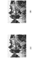
二重液晶技術では、液晶を二重に配置する際、液晶パネル同士の接触による傷等を防止するため液晶パネル間に空間を設けることが多い。また、液晶パネル間に空間を設けなくても、液晶パネル自体の厚みによる空間が存在する。この空間の影響により、例えば図6のような画像を真正面から見た場合、図7のように一本の線に見えるが、図8のように斜め方向から画像を見た場合、観察角度(方向)によっては2つの液晶パネルの同じ位置に表示されている画像が異なる位置に見える場合がある。この場合、図8のように二本の線に見える。この現象は、文字列や数字列等の高周波の画像で階調段差のはっきりした画像で特に顕著であり、文字や数字が二重に見えて視認性が良くないという問題がある。
この問題を解決する方法として、バックライト側液晶の透光領域を、入力画像信号の表示領域を内包する領域とすることで、観察方向によらず視認性が低下することを抑制する技術が開示されている。
In the dual liquid crystal technology, when arranging liquid crystals in a double manner, a space is often provided between the liquid crystal panels in order to prevent scratches or the like due to contact between the liquid crystal panels. Further, even if no space is provided between the liquid crystal panels, there is a space due to the thickness of the liquid crystal panel itself. Due to the effect of this space, for example, when the image as shown in FIG. 6 is viewed from directly in front, it looks like a single line as in FIG. 7, but when the image is viewed from an oblique direction as in FIG. Depending on the direction), images displayed at the same position on the two liquid crystal panels may appear at different positions. In this case, it looks like two lines as shown in FIG. This phenomenon is particularly remarkable in a high-frequency image such as a character string or a number string in which a gradation step is clear, and there is a problem that letters and numbers look double and visibility is not good.
As a method for solving this problem, a technique is disclosed in which the transmissive area of the backlight-side liquid crystal is set as an area including a display area of an input image signal, thereby suppressing a decrease in visibility regardless of an observation direction. Have been.
上述のように、二重液晶技術では観察角度によって画像が二重に見える現象が発生する場合がある。しかし、二重液晶でも視認性が低下しにくい(二重に見えにくい)画像もある。例えば、自然画やマンモグラフィーの診断画像等、階調変化が滑らかな画像では、上記の従来技術に開示された技術を用いずに1枚目と2枚目の液晶パネルを同一の表示にしても画像が二重に見える現象は起こりにくい。このような画像の表示において上記の従来技術を適用すると、画像が二重に見える現象は抑制できる。しかし、解像度が荒く輝度差のはっきりしない表示となったり、正面から見た場合にはハローが発生したり、二重液晶の利点である面内コントラストの向上の効果が少なくなったりする。 As described above, in the dual liquid crystal technology, a phenomenon that an image looks double depending on an observation angle may occur. However, there are also images in which the visibility is hardly reduced even with the double liquid crystal (it is hard to see double). For example, in an image having a smooth gradation change, such as a natural image or a diagnostic image of mammography, even if the first and second liquid crystal panels are displayed in the same manner without using the technology disclosed in the above-described conventional technology. The phenomenon that the image looks double is unlikely to occur. When the above-described conventional technique is applied to the display of such an image, the phenomenon in which the image looks double can be suppressed. However, the display has a rough resolution and a luminance difference is not clear, a halo occurs when viewed from the front, and the effect of improving the in-plane contrast, which is an advantage of the dual liquid crystal, is reduced.
そこで、本発明は、二重液晶を備えた表示装置において、表示する画像に応じて最適な表示制御を行うことで高い表示画質と良好な視認性とを両立させることを目的とする。 Accordingly, it is an object of the present invention to achieve both high display image quality and good visibility by performing optimal display control according to an image to be displayed in a display device including a double liquid crystal.
本発明は、第1表示パネルと、
前記第1表示パネルの背面側に配置される第2表示パネルと、
前記第2表示パネルの背面側に配置される発光部と、
第1表示モードと、前記第1表示モードよりも観察者の視差による二重像の発生が抑制される第2表示モードと、のうちいずれかを、入力画像に付加された前記入力画像の種類を示す情報に基づいて選択する選択手段と、
入力画像全体に対して、前記選択手段に選択された表示モードに応じた画像処理を行って処理画像を生成する生成手段と、
を備え、
前記第2表示パネルは、前記処理画像に基づいて、前記発光部から発せられた光を変調し、
前記第1表示パネルは、前記入力画像に基づいて、前記第2表示パネルから出力された光を変調する、
ことを特徴とする表示装置である。
The present invention provides a first display panel,
A second display panel disposed on the back side of the first display panel;
A light emitting unit disposed on the back side of the second display panel;
The type of the input image, wherein one of a first display mode and a second display mode in which generation of a double image due to parallax of an observer is suppressed more than the first display mode is added to the input image Selecting means for selecting based on information indicating
Generating means for performing image processing according to the display mode selected by the selecting means on the entire input image to generate a processed image;
With
The second display panel modulates light emitted from the light emitting unit based on the processed image,
The first display panel modulates light output from the second display panel based on the input image;
A display device characterized in that:
本発明は、第1表示パネルと、
前記第1表示パネルの背面側に配置される第2表示パネルと、
前記第2表示パネルの背面側に配置される発光部と、
を備える表示装置の制御方法であって、
第1表示モードと、前記第1表示モードよりも観察者の視差による二重像の発生が抑制される第2表示モードと、のうちいずれかを、入力画像に付加された前記入力画像の種類を示す情報に基づいて選択する選択ステップと、
入力画像全体に対して、前記選択ステップで選択された表示モードに応じた画像処理を行って処理画像を生成する生成ステップと、
前記発光部から発せられた光を前記第2表示パネルにより前記処理画像に基づいて変調し、前記第2表示パネルから出力された光を前記第1表示パネルにより前記入力画像に基づいて変調することにより画像を表示する表示ステップと
を有することを特徴とする表示装置の制御方法である。
The present invention provides a first display panel,
A second display panel disposed on the back side of the first display panel;
A light emitting unit disposed on the back side of the second display panel;
A display device control method comprising:
The type of the input image, wherein one of a first display mode and a second display mode in which generation of a double image due to parallax of an observer is suppressed more than the first display mode is added to the input image A selection step of selecting based on information indicating
For the entire input image, a generation step of generating a processed image by performing image processing corresponding to the display mode selected by the selecting step,
Modulating the light emitted from the light emitting section by the second display panel based on the processed image, and modulating the light output from the second display panel by the first display panel based on the input image. And a display step of displaying an image according to the following.
本発明は、上記方法の各ステップをコンピュータに実行させるためのプログラムである。
本発明は、上記プログラムを記憶するコンピュータが読み取り可能な記憶媒体である。
The present invention is a program for causing a computer to execute each step of the above method .
The present invention is a computer-readable storage medium storing the above program.
本発明によれば、二重液晶を備えた表示装置において、表示する画像に応じて最適な表示制御を行うことで高い表示画質と良好な視認性とを両立させることができる。 ADVANTAGE OF THE INVENTION According to this invention, in the display apparatus provided with the double liquid crystal, high display image quality and good visibility can be made compatible by performing optimal display control according to the image to be displayed.
(実施例1)
本発明の実施例1の表示装置について説明する。
図1は、実施例1の表示装置の構成を示すブロック図である。
表示装置は第1表示手段である表面側の第1液晶パネル112と、第2表示手段であるバックライト101及びバックライト側に配置されバックライト101からの光を変調する第2液晶パネル111と、を有する。第2液晶パネル111は第1液晶パネル112を通して視認可能である。液晶パネルを二重にする場合、モアレを防止するため、第1液晶パネル112に対し一定の間隔をあけて背面側に第2液晶パネル111を設けるか、又は拡散シート102のような光学シートを挟んで第1液晶パネル112の背面側に第2液晶パネル111を設ける。実施例1では、拡散シート102を液晶パネル間に挟にで設け、液晶パネル間隔はなるべく空けない構成とした。
(Example 1)
A display device according to a first embodiment of the present invention will be described.
FIG. 1 is a block diagram illustrating the configuration of the display device according to the first embodiment.
The display device includes a first
液晶パネルの表示モードとして、IPS(In Plane Switching)、VA(Vertical Alignment)、TN(twisted nematic)等の種々の方式がある。どの方式の液晶パネルを有
する表示装置にも本発明は適用可能だが、実施例1では第2液晶パネル111及び第1液晶パネル112はIPS方式の液晶パネルであるとする。
There are various types of display modes of the liquid crystal panel, such as IPS (In Plane Switching), VA (Vertical Alignment), and TN (twisted nematic). Although the present invention can be applied to a display device having any type of liquid crystal panel, in the first embodiment, the second
図2は実施例1の表示装置の機能構成を示す図である。
図2において、画像処理部202は、受信した画像信号201(第1画像データ)の内容に応じて所定の画像処理を施し、第2画像データを生成する。画像処理部202は、第1画像データの内容に応じて、第2液晶パネル111と第1液晶パネル112のそれぞれに第1画像データ又は第2画像データを出力する。
タイミング生成部203は、第2液晶パネル111及び第1液晶パネル112に画像データを出力するタイミングを制御し、両液晶パネルにおける画像表示を同期させる。
FIG. 2 is a diagram illustrating a functional configuration of the display device according to the first embodiment.
2, the
The
図3は実施例1の処理を表すフローチャートである。
ステップS301で画像信号(第1画像データ)が入力される。
ステップS302において、画像処理部202は判別処理を行う。画像処理部202は、判別処理において、第1画像データのが広視野角モードと狭視野角モードのどちらに適した画像かを判別する。
FIG. 3 is a flowchart illustrating the processing of the first embodiment.
In step S301, an image signal (first image data) is input.
In step S302, the
狭視野角モードとは、高コントラスト表示が得られるように第2液晶パネル111と第1液晶パネル112に同じ画像(第1画像データに基づく画像)を表示させる表示モードである。狭視野角モードでは、第1液晶パネル112と第2液晶パネル111との両方に第1画像データに基づく画像を表示させる。
The narrow viewing angle mode is a display mode in which the same image (an image based on the first image data) is displayed on the second
広視野角モードとは、観察方向によらず画像が二重に観察されにくくするように、広視野角モード用の画像(第2画像データ)を生成し、それを第2液晶パネル111に表示する表示モードである。広視野角モードでは、第1液晶パネル112に第1画像データに基づく画像を表示させ、第2液晶パネル111に第2画像データに基づく画像を表示させる。第2画像データは、第1液晶パネル112と第2液晶パネル111の同じ位置にある画素が、観察者による観察方向に応じて生じる視差により異なる位置に視認されることによる二重像を抑制するために第2液晶パネル111に表示させる画像データである。
In the wide viewing angle mode, an image (second image data) for the wide viewing angle mode is generated and displayed on the second
例えば、文字列(テキスト)やグラフィックスのパターンからなる画像のように、画像内の輝度変化(階調変化)が比較的大きい画像は、観察方向が斜めになると二重に見えやすい。しかし、観察者にとっての表示品質の感じ方においてコントラストが余り大きく影響しない。すなわち高コントラストで表示しなくても観察者は表示品質が低いとは感じにくい。そのため高コントラストで表示する必要性が比較的低い。このような画像を画像処理部202は広視野角モードに適した画像と判別する。
For example, an image having a relatively large luminance change (gradation change) in an image, such as an image composed of a character string (text) or a graphic pattern, is likely to appear double when the observation direction is oblique. However, the contrast does not significantly affect how the viewer perceives the display quality. That is, even if the display is not performed with a high contrast, the viewer does not easily feel that the display quality is low. Therefore, the necessity of displaying with high contrast is relatively low. The
一方、映画や風景等の自然画像(実写画像)は、画像内の輝度変化(階調変化)が比較的小さく滑らであるため、観察方向が斜めになっても二重に見えにくい(二重になってい
ることが視認されにくい)。しかし、コントラストが観察者にとっての表示品質の感じ方に影響が大きい。すなわちコントラストが低いと表示品質が低いと感じやすい。このような画像を画像処理部202は狭視野角モードに適した画像と判別する。
On the other hand, a natural image (actual image) such as a movie or a landscape has a relatively small luminance change (gradation change) in the image and is smooth, so that even if the observation direction is oblique, it is difficult to see a double image (double image). Is difficult to see). However, the contrast greatly affects how the viewer perceives the display quality. That is, when the contrast is low, it is easy to feel that the display quality is low. The
実施例1では、画像処理部202は、画像解析により第1画像データの画像の内容の判別を行う。例えば、画像処理部202は、画像を画素単位でスキャンし、画素の階調変化の波形が矩形波のように急峻な変化か否かを判別し、その判別結果に基づき、広視野角モードが適した画像か狭視野角モードが適した画像かを判別する。例えば、画像処理部202は、画像内の階調変化(輝度変化)の大きさを示す特徴量を求め、所定の閾値と比較する。輝度変化の大きさが閾値より大きい場合、広視野角モードが適した画像と判定し、輝度変化の大きさが閾値以下の場合、狭視野角モードが適した画像と判定するようにすることができる。なお、画像の種類を判別する方法は、これに限定されず他の方法を用いても良い。
In the first embodiment, the
ステップS303において、画像処理部202は、ステップS302の判別結果に基づき、表示モードを広視野角モード又は狭視野角モードに切り替える処理を行う。狭視野角モードの場合、ステップS304に進む。広視野角モードの場合、ステップS305に進む。
ステップS304において、画像処理部202は、第2液晶パネル111及び第1液晶パネル112で同じ画像を出力する。
ステップS305において、画像処理部202は、第2液晶パネル111に表示させるための画像を生成する。この処理において、画像処理部202は、元の入力画像よりも粗い画像(低解像度の画像)を表示する。
In step S303, the
In step S304, the
In step S305, the
広視野角モードにおいて第2液晶パネル111に表示させる画像の生成方法を図4、図5を用いて説明する。
図4において、観察者が画面を観察する方向を表す観察角度θ(視野角)、液晶パネル間距離d、画素ピッチpとする。斜めから観察したときに二重に見えることを抑制するために、広視野角モードでは、元画像(第1液晶パネル112に表示する画像)の各画素をx画素ずつ周囲に拡げることにより生成した画像を第2液晶パネル111に表示する。xは以下の式で決めることができる。
![]()
屈折率を考慮する場合は図5のようにして求める。観察角度θに対し、第2液晶パネル111と第1液晶パネル112の間を進む光線の第1液晶パネル112に対する角度をφ、空気の屈折率をNa、液晶パネルの屈折率をNpとすると、スネルの法則より以下の式が成り立つ。

この関係から、観察確度θから見た場合、第2液晶パネル111と第1液晶パネル112との表示位置のズレ量rは以下の式で表すことができる。
よって、二重に見えることを抑制するには、元画像の各画素を以下式で決まるx画素だけ周囲に拡げることにより生成した画像を第2液晶パネル111に表示すれば良い。
![]()
ただし、屈折率を考慮した例では、第2液晶パネル111に表示する画像の解像度の低下量が小さくなるので、二重に見えることを十分に抑制できない場合がある。例えば、2枚の液晶パネル同士が微妙な位置ずれを起こした場合には、二重に見えてしまうことがある。
A method of generating an image to be displayed on the second
In FIG. 4, an observation angle θ (viewing angle) representing a direction in which the observer observes the screen, a distance d between the liquid crystal panels, and a pixel pitch p are set. In the wide viewing angle mode, each pixel of the original image (the image displayed on the first liquid crystal panel 112) is generated by expanding each pixel by x pixels in the wide viewing angle mode in order to suppress double viewing when obliquely observed. The image is displayed on the second
![]()
When the refractive index is considered, it is obtained as shown in FIG. With respect to the observation angle θ, assuming that the angle of the light beam traveling between the second
From this relationship, when viewed from the observation accuracy θ, the deviation amount r of the display position between the second
Therefore, in order to suppress the double appearance, an image generated by expanding each pixel of the original image around x pixels determined by the following equation may be displayed on the second
![]()
However, in the example in which the refractive index is taken into consideration, the amount of reduction in the resolution of the image displayed on the second
上述した広視野角モード選択時の第2液晶パネル111に表示する画像の生成方法は一例であり、これに限られない。例えば、液晶パネル間に拡散シートを配置した場合はその拡散の程度に応じて広視野角モード時に第2液晶パネル111に表示する画像を生成する。
The method of generating an image to be displayed on the second
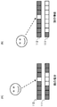
次に、狭視野角モードと広視野角モードのそれぞれにおける画像の見え方について説明する。ここでは、図6に示すような、黒地に一本の縦の白線があるような画像を表示した場合の見え方を例に説明する。このようなパターン画像は、観察方向が斜めになると二重に見えやすい画像であり、広視野角モードが適した画像である。 Next, how to view an image in each of the narrow viewing angle mode and the wide viewing angle mode will be described. Here, an example will be described in which an image in which a vertical white line is displayed on a black background as shown in FIG. 6 is displayed. Such a pattern image is an image that is likely to be double-viewed when the observation direction is oblique, and is an image suitable for the wide viewing angle mode.
パターン画像を狭視野角モードで表示した場合、正面から見れば表示が重なるので、図7のように一本の線に見える。しかし、斜めから画像を見ると、図8のように2本線に見えてしまう。一方、広視野角モードで表示した場合、斜めから見てもこのように画像が二重に見えることが抑制され、図7のように1本線での表示に見える。 When the pattern image is displayed in the narrow viewing angle mode, the display overlaps when viewed from the front, so that it looks like a single line as shown in FIG. However, when the image is viewed obliquely, it looks like two lines as shown in FIG. On the other hand, when the image is displayed in the wide viewing angle mode, the image is suppressed from being double seen even when viewed obliquely, and is displayed as a single line as shown in FIG.
広視野角モードで表示した画像を正面から見た場合、画像の周囲が明るくなるハローが視認される可能性がある。しかし、一般的な表示装置でバックライトの局所減光(ローカルディミング)を行う場合に観察されるハローと比較すると、ハローの度合は小さく、視認される画像の画質への影響は小さいと言える。従って、広視野角モードで表示しても画面内のコントラスト低下は抑制される。従って、文字やGUI(Graphical User Interface)等のようなパターン画像では広視野角モードで表示するのが好ましい。 When an image displayed in the wide viewing angle mode is viewed from the front, there is a possibility that a halo in which the periphery of the image becomes brighter is visually recognized. However, compared with the halo observed when performing local dimming (local dimming) of the backlight in a general display device, the degree of the halo is small, and it can be said that the influence on the image quality of the visually recognized image is small. Therefore, even when the image is displayed in the wide viewing angle mode, the decrease in the contrast in the screen is suppressed. Therefore, it is preferable to display a pattern image such as a character or a GUI (Graphical User Interface) in the wide viewing angle mode.
一方、図9(A)に示すような自然画像を広視野角モードで表示した場合の見え方を図9(B)に模式的に示す。自然画像を広視野角モードで表示すると、元画像(図9(A))に対して解像度を低下させた画像を生成して第2液晶パネル111に表示させるので、図9(B)のようにぼやけたように見える可能性がある。また、各画素を周囲に拡げて生成した画像を第2液晶パネル111に表示するので、全体的に透過率が上がることになる。そのため、二重液晶の利点であるコントラスト向上の効果が制限される。自然画像の場合、狭視野角モードで表示して斜めから観察しても二重になっていることが視認されにくい。また、狭視野角モードで表示すれば、コントラスト向上の効果が低下することを抑制できる。従って、図9(A)のような自然画像では狭視野角モードで表示するのが好まし
い。
On the other hand, FIG. 9B schematically shows how a natural image as shown in FIG. 9A is displayed in the wide viewing angle mode. When a natural image is displayed in the wide viewing angle mode, an image having a reduced resolution with respect to the original image (FIG. 9A) is generated and displayed on the second
以上、実施例1によれば、画像が図6のパターン画像のような二重に見えやすい画像であるか図9(A)の自然画像のように二重に見えにくい画像であるかに応じて表示モードを切り替える。二重に見えやすい画像を広視野角モードで表示することで二重に見えることを抑制することができるとともに、二重に見えにくい画像を狭視野角モードで表示することで二重液晶によるコントラスト向上の効果が低下することを抑制することができる。 As described above, according to the first embodiment, depending on whether the image is an image that is easily double-viewed like the pattern image of FIG. 6 or an image that is hardly double-viewable like the natural image of FIG. To switch the display mode. By displaying an image that is easily viewed in double mode in the wide viewing angle mode, it is possible to suppress double viewing, and by displaying an image that is difficult to see in double mode in the narrow viewing angle mode, the contrast of the double liquid crystal display is achieved. A reduction in the effect of the improvement can be suppressed.
(実施例2)
実施例2の表示装置について説明する。
実施例2では、第1画像データが、画像の内容(広視野角モードを適用する画像か狭視野角モードを適用する画像か)を示す付加情報を含むを想定する。この場合、実施例1のように画像解析による画像の種類の判別を行う必要はない。実施例2では、図10に示すように、画像処理部202は、図3のステップS302の代わりにステップS401において、第1画像データから画像の内容(種類)を示す付加情報を取得する処理を行う。続くステップS303では、画像処理部202は、第1画像データから取得した付加情報に基づき、表示モードを広視野角モード又は狭視野角モードに切り替える処理を行う。例えばHDMI(登録商標)インターフェースのように、画像信号とともに種々の付加情報を伝送できる構成では、この付加情報を用いて表示モードを決定することができる。第2液晶パネル111に表示する画像の生成方法は実施例1と同様である。
(Example 2)
A display device according to the second embodiment will be described.
In the second embodiment, it is assumed that the first image data includes additional information indicating the content of the image (whether the image applies the wide viewing angle mode or the image applying the narrow viewing angle mode). In this case, it is not necessary to determine the type of image by image analysis as in the first embodiment. In the second embodiment, as shown in FIG. 10, the
(実施例3)
実施例3の表示装置について説明する。
実施例3では、画像内の領域毎に予め画像の内容(種類)が決まっている場合を想定する。この場合、図11に示すように、画像処理部202は、ステップS301に続くステップS501において、画像内の領域毎に、対応付けられた画像の内容の情報を取得する。そして続くステップS502において、画像処理部202は、領域毎に画像の内容に応じて狭視野角モードと広視野角モードを切り替える。なお、画像内の領域毎に予め表示モードが決まっているとしても良い。この場合、画像処理部202は、画像内の領域毎に、対応付けられた表示モードの情報を取得し、取得した表示モードに基づき狭視野角モードと広視野角モードの切り替えを行う。
(Example 3)
A display device according to the third embodiment will be described.
In the third embodiment, it is assumed that the content (type) of the image is determined in advance for each region in the image. In this case, as shown in FIG. 11, in step S501 subsequent to step S301, the
画面内の領域毎に表示画像の種類が決まっている例としては、図12に示すような医療画像用ビューワがある。図12の医療画像用ビューワでは、画面内に患者のレントゲン画像を表示する領域Aと、診断情報を示す文字列やメニューバー等のGUI(Graphical User Interface)を構成する画像(自然画像でない画像)が表示される領域B,Cがある。領域Aには狭視野角モードが対応付けられ、領域B,Cは広視野角モードが対応付けられている。このような画面内の領域の情報や、各領域に対応付けられた画像の種類の情報(又は表示モードの情報)は、実施例2と同様に画像信号と共に送信される情報を取得するようにしても良いし、他の方法で取得するようにしても良い。例えば、実施例1と同様に画像解析により領域情報及び画像種類情報を判別し、判別結果を記憶装置(不図示)に記憶させておき、同じレイアウトの画像信号が入力される間は当該記憶させた領域情報及び画像種類情報に基づき領域毎の表示モードの切り替えを行う。 An example in which the type of display image is determined for each area in the screen is a medical image viewer as shown in FIG. In the medical image viewer of FIG. 12, an image A (a non-natural image) constituting a GUI (Graphical User Interface) such as a character string indicating diagnostic information and a menu bar is displayed on the screen in a region A for displaying an X-ray image of a patient. Are displayed in areas B and C. The area A is associated with the narrow viewing angle mode, and the areas B and C are associated with the wide viewing angle mode. The information of the area in the screen and the information of the type of the image associated with each area (or the information of the display mode) are obtained by acquiring the information transmitted together with the image signal as in the second embodiment. Alternatively, it may be obtained by another method. For example, the area information and the image type information are determined by image analysis in the same manner as in the first embodiment, and the determination result is stored in a storage device (not shown), and stored while an image signal of the same layout is input. The display mode is switched for each area based on the area information and the image type information.
(実施例4)
実施例4の表示装置について説明する。
図13は、実施例4の表示装置の構成を示すブロック図である。図1との相違点は、ユーザが指示を入力することができる入力部602を備えている点である。実施例4の表示装置は、入力部602により、ユーザが所望の表示モードを選択(指定)する指示を表示装置に入力することができる。画像処理部202は、ユーザに指定された表示モードに切
り替える制御を行う。例えば実施例1の制御により自動で選択され適用された表示モードによる表示が観察者の満足するものではなかった場合に、観察者が手動で好みの表示モードで画像を表示させることができる。
(Example 4)
A display device according to a fourth embodiment will be described.
FIG. 13 is a block diagram illustrating the configuration of the display device according to the fourth embodiment. The difference from FIG. 1 is that an input unit 602 that allows a user to input an instruction is provided. In the display device according to the fourth embodiment, the input unit 602 allows the user to input an instruction to select (designate) a desired display mode into the display device. The
入力部602は、さらに、広視野角モードにおいて第2液晶パネル111に表示させる第2画像データを生成する際の画像処理の強度(広視野角モードレベル)を指定するユーザの指示を入力することができるようにしても良い。広視野角モードレベルは、例えば、「強」「中」「弱」「切り」(狭視野角モード)のような複数の段階に設定できるようにしても良いし、連続値による無段階調整ができるようにしても良い。実施例4では、ユーザの好みでレベルを設定できるようにする。画像処理部202は、ユーザに設定されたレベルに基づき、第2液晶パネル111に表示させる画像を生成する。
The input unit 602 further inputs a user's instruction to specify the intensity of image processing (wide viewing angle mode level) when generating the second image data to be displayed on the second
入力部602は、例えば表示装置にGUIを表示させ、キーボードやマウス等の入力装置により、視野角モードレベルを設定するユーザからの指示入力を受け付ける。また、入力部602は表示装置本体に設けられたボタンやリモコン等によりユーザからの指示入力を受け付けるようにしても良い。入力部602の構成はこれらに限定されない。 The input unit 602 displays a GUI on a display device, for example, and receives an instruction input from a user for setting a viewing angle mode level using an input device such as a keyboard or a mouse. In addition, the input unit 602 may receive an instruction input from a user using a button, a remote controller, or the like provided on the display device body. The configuration of the input unit 602 is not limited to these.
自動選択された表示モードにユーザが満足できないことが考えられる状況としては、例えば、ポスタリゼーション画像やアニメ画像を表示する場合が考えられる。このような画像では、観察者は高コントラストでの表示(狭視野角モード)を期待すると考えられるが、自動判別の場合、判別方法の設定にもよるが、自然画像ではないことにより広視野角モードが選択されてしまう可能性がある。このような場合、実施例4では、ユーザが手動で表示モードを狭視野角モードに設定できるので、ユーザは好みに合った表示で画像を観察することができる。 As a situation where the user may not be satisfied with the automatically selected display mode, for example, a case where a posterization image or an animation image is displayed may be considered. In such an image, the observer is expected to expect a display with a high contrast (narrow viewing angle mode). In the case of automatic discrimination, although it depends on the setting of the discrimination method, it is not a natural image, so the wide viewing angle is not obtained. The mode may be selected. In such a case, in the fourth embodiment, the user can manually set the display mode to the narrow viewing angle mode, so that the user can observe an image with a display that suits his or her preference.
画像処理部202は、ユーザに設定されたレベルが「弱」の場合、図14(A)のように元画像の画素を拡げる大きさを小さくし、レベルが「強」の場合、図14(B)のように元画像の画素を拡げる大きさを大きくする。レベル「強」で生成された画像を第2液晶パネル111に表示させた場合、図14(B)に示すように、画面に対する観察角度が大きくなった場合でも、二重に見えるのを抑制できる。一方、レベル「弱」で生成された画像を第2液晶パネル111に表示させた場合、図14(A)に示すように、観察角度が小さい場合に二重に見えるのを抑制できるとともに表示コントラストの低下を抑制できる。
When the level set by the user is “weak”, the
実施例4によれば、ユーザにとって狭視野角モードでの表示が望ましい画像に対して自動判別により広視野角モードが選択された場合でも、ユーザが手動で表示モードを設定できるので、ユーザの好みに合った表示が可能である。 According to the fourth embodiment, the display mode can be manually set by the user even when the wide viewing angle mode is selected by the automatic determination for the image for which the display in the narrow viewing angle mode is desirable for the user. Can be displayed in accordance with.
以上、本発明の実施例についていくつか具体的に説明したが、本発明はこれらの実施例に限定されず、その要旨の範囲内で種々の変形及び変更が可能である。例えば、上記の各実施例では表示面側から順に第1液晶パネル112、第1液晶パネル及びバックライト101を重ね合わせた構成の表示装置への適用例を説明した。液晶パネルと有機EL(Electro-Luminescence)パネルを重ね合わせ、有機ELパネルから発せられた光を液晶パネルで変調して液晶パネルの透過光により画像を表示する構成の表示装置にも本発明は適用できる。この場合、第1液晶パネル112が第1表示手段、有機ELパネルが第2表示手段である。狭視野角モードでは液晶パネルと有機ELパネルに同じ画像を表示させ、広視野角モードでは有機ELパネルに低解像度画像を表示させる。
Although several embodiments of the present invention have been specifically described above, the present invention is not limited to these embodiments, and various modifications and changes can be made within the scope of the invention. For example, in each of the above-described embodiments, an example of application to a display device having a configuration in which the first
(その他の実施例)
本発明は、上述の実施形態の1以上の機能を実現するプログラムを、ネットワーク又は記憶媒体を介してシステム又は装置に供給し、そのシステム又は装置のコンピュータにお
ける1つ以上のプロセッサーがプログラムを読出し実行する処理でも実現可能である。また、1以上の機能を実現する回路(例えば、ASIC)によっても実現可能である。
(Other Examples)
The present invention supplies a program for realizing one or more functions of the above-described embodiments to a system or an apparatus via a network or a storage medium, and one or more processors in a computer of the system or the apparatus read and execute the program. This processing can be realized. Further, it can also be realized by a circuit (for example, an ASIC) that realizes one or more functions.
111:第2液晶パネル、112:第1液晶パネル、202:画像処理部 111: second liquid crystal panel, 112: first liquid crystal panel, 202: image processing unit
Claims (26)
前記第1表示パネルの背面側に配置される第2表示パネルと、
前記第2表示パネルの背面側に配置される発光部と、
第1表示モードと、前記第1表示モードよりも観察者の視差による二重像の発生が抑制される第2表示モードと、のうちいずれかを、入力画像に付加された前記入力画像の種類を示す情報に基づいて選択する選択手段と、
入力画像全体に対して、前記選択手段に選択された表示モードに応じた画像処理を行って処理画像を生成する生成手段と、
を備え、
前記第2表示パネルは、前記処理画像に基づいて、前記発光部から発せられた光を変調し、
前記第1表示パネルは、前記入力画像に基づいて、前記第2表示パネルから出力された光を変調する、
ことを特徴とする表示装置。 A first display panel;
A second display panel disposed on the back side of the first display panel;
A light emitting unit disposed on the back side of the second display panel;
The type of the input image, wherein one of a first display mode and a second display mode in which generation of a double image due to parallax of an observer is suppressed more than the first display mode is added to the input image Selecting means for selecting based on information indicating
Generating means for performing image processing according to the display mode selected by the selecting means on the entire input image to generate a processed image;
With
The second display panel modulates light emitted from the light emitting unit based on the processed image,
The first display panel modulates light output from the second display panel based on the input image;
A display device characterized by the above-mentioned.
ことを特徴とする請求項1に記載の表示装置。 When the second display mode is selected, the generation unit performs a process of expanding pixels of the input image to generate the processed image.
The display device according to claim 1, wherein:
ことを特徴とする請求項1または2に記載の表示装置。 When the first display mode is selected, the generating unit outputs the input image as the processed image;
The display device according to claim 1 or 2, characterized in that.
前記第1表示パネルの背面側に配置される第2表示パネルと、
前記第2表示パネルの背面側に配置される発光部と、
第1表示モードと、前記第1表示モードよりも観察者の視差による二重像の発生が抑制される第2表示モードと、を含む複数の表示モードのうちいずれかを選択するためのユーザの選択指示を入力する入力手段と、
前記入力手段により入力された選択指示に応じて、前記複数の表示モードのうちいずれ
かの表示モードを選択する選択手段と、
入力画像全体に対して、前記選択手段により選択された表示モードに応じた画像処理を行って処理画像を生成する生成手段と、
を備え、
前記第2表示パネルは、前記処理画像に基づいて、前記発光部から発せられた光を変調し、
前記第1表示パネルは、前記入力画像に基づいて、前記第2表示パネルから出力された光を変調することを特徴とする表示装置。 A first display panel;
A second display panel disposed on the back side of the first display panel;
A light emitting unit disposed on the back side of the second display panel;
The user is required to select one of a plurality of display modes including a first display mode and a second display mode in which generation of a double image due to parallax of an observer is suppressed more than the first display mode. Input means for inputting a selection instruction;
One of the plurality of display modes according to a selection instruction input by the input unit.
And selection means for selecting a Kano display mode,
For the entire input image, a generation unit for generating a processed image by performing image processing corresponding to the display mode selected by said selection means,
With
The second display panel modulates light emitted from the light emitting unit based on the processed image,
The display device, wherein the first display panel modulates light output from the second display panel based on the input image.
前記第1表示モードが選択された場合の第1拡大範囲より、前記選択手段により前記第2表示モードが選択された場合の第2拡大範囲の方が広い、
ことを特徴とする請求項4に記載の表示装置。 The generation unit determines the pixel value of a pixel included in an enlarged range from the pixel of the processed image corresponding to the target pixel based on the pixel value of the target pixel of the input image, and generates the processed image. So,
A second enlargement range when the second display mode is selected by the selection means is wider than a first enlargement range when the first display mode is selected;
The display device according to claim 4 , wherein:
ことを特徴とする請求項4または5に記載の表示装置。 The selecting means may suppress generation of a double image due to parallax of an observer in the first display mode, and suppress generation of a double image due to parallax of the observer in the third display mode. The display mode can be further selected,
The display device according to claim 4, wherein:
ことを特徴とする請求項1から6のいずれか1項に記載の表示装置。 The first display panel and the second display panel are liquid crystal panels, respectively.
Display device according to any one of claims 1 6, characterized in that.
ことを特徴とする請求項1から7のいずれか1項に記載の表示装置。 When the second display mode is selected, the contrast of an image displayed on the first display panel is lower than when the first display mode is selected.
Display device according to any one of claims 1 to 7, characterized in that.
ことを特徴とする請求項1から8のいずれか1項に記載の表示装置。 The second processing image generated when the second display mode is selected by the selection unit is better than the first processing image generated when the first display mode is selected by the selection unit. It is a blurry image,
The display device according to any one of claims 1 to 8 , wherein:
ことを特徴とする請求項1から9のいずれか1項に記載の表示装置。The display device according to claim 1, wherein:
ことを特徴とする請求項1から10のいずれか1項に記載の表示装置。The display device according to claim 1, wherein:
前記第1表示パネルは、前記第2表示パネルから透過した光を前記入力画像に基づく透過率で透過することによって、画像を表示する、The first display panel displays an image by transmitting light transmitted from the second display panel at a transmittance based on the input image.
ことを特徴とする請求項1から11のいずれか1項に記載の表示装置。The display device according to claim 1, wherein:
前記第1表示パネルの背面側に配置される第2表示パネルと、
前記第2表示パネルの背面側に配置される発光部と、
を備える表示装置の制御方法であって、
第1表示モードと、前記第1表示モードよりも観察者の視差による二重像の発生が抑制される第2表示モードと、のうちいずれかを、入力画像に付加された前記入力画像の種類を示す情報に基づいて選択する選択ステップと、
入力画像全体に対して、前記選択ステップで選択された表示モードに応じた画像処理を行って処理画像を生成する生成ステップと、
前記発光部から発せられた光を前記第2表示パネルにより前記処理画像に基づいて変調し、前記第2表示パネルから出力された光を前記第1表示パネルにより前記入力画像に基づいて変調することにより画像を表示する表示ステップと、
を有することを特徴とする表示装置の制御方法。 A first display panel;
A second display panel disposed on the back side of the first display panel;
A light emitting unit disposed on the back side of the second display panel;
A display device control method comprising:
The type of the input image, wherein one of a first display mode and a second display mode in which generation of a double image due to parallax of an observer is suppressed more than the first display mode is added to the input image A selection step of selecting based on information indicating
For the entire input image, a generation step of generating a processed image by performing image processing corresponding to the display mode selected by the selecting step,
Modulating the light emitted from the light emitting section by the second display panel based on the processed image, and modulating the light output from the second display panel by the first display panel based on the input image. A display step of displaying an image by
A control method for a display device, comprising:
ことを特徴とする請求項13に記載の表示装置の制御方法。 When the second display mode is selected, in the generation step, a process of expanding the pixels of the input image is performed to generate the processed image.
The method for controlling a display device according to claim 13 , wherein:
ことを特徴とする請求項13または14のいずれか1項に記載の表示装置の制御方法。 When the first display mode is selected, in the generating step, the input image is output as the processed image;
The method of controlling a display device according to claim 13, wherein:
前記第1表示パネルの背面側に配置される第2表示パネルと、
前記第2表示パネルの背面側に配置される発光部と、
を備える表示装置の制御方法であって、
第1表示モードと、前記第1表示モードよりも観察者の視差による二重像の発生が抑制される第2表示モードと、を含む複数の表示モードのうちいずれかを選択するためのユーザの選択指示を入力する入力ステップと、
前記入力ステップにおいて入力された選択指示に応じて、前記複数の表示モードのうちいずれかの表示モードを選択する選択ステップと、
入力画像全体に対して、前記選択ステップで選択された表示モードに応じた画像処理を行って処理画像を生成する生成ステップと、
前記発光部から発せられた光を前記第2表示パネルにより前記処理画像に基づいて変調し、前記第2表示パネルから出力された光を前記第1表示パネルにより前記入力画像に基づいて変調することにより画像を表示する表示ステップと、
を有することを特徴とする表示装置の制御方法。 A first display panel;
A second display panel disposed on the back side of the first display panel;
A light emitting unit disposed on the back side of the second display panel;
A display device control method comprising:
The user is required to select one of a plurality of display modes including a first display mode and a second display mode in which generation of a double image due to parallax of an observer is suppressed more than the first display mode. An input step of inputting a selection instruction;
A selection step of selecting one of the plurality of display modes according to the selection instruction input in the input step;
For the entire input image, a generation step of generating a processed image by performing image processing corresponding to the display mode selected by the selecting step,
Modulating the light emitted from the light emitting section by the second display panel based on the processed image, and modulating the light output from the second display panel by the first display panel based on the input image. A display step of displaying an image by
A control method for a display device, comprising:
前記第1表示モードが選択された場合の第1拡大範囲より、前記選択ステップで前記第2表示モードが選択された場合の第2拡大範囲の方が広い、
ことを特徴とする請求項16に記載の表示装置の制御方法。 In the generating step, based on a pixel value of a target pixel of the input image, a pixel value of a pixel included in an enlarged range is determined from a pixel of the processed image corresponding to the target pixel, and the processed image is generated. So,
A second enlarged range when the second display mode is selected in the selecting step is wider than a first enlarged range when the first display mode is selected;
The method of controlling a display device according to claim 16 , wherein:
ことを特徴とする請求項16または17に記載の表示装置の制御方法。 In the selecting step, a third image in which generation of a double image due to parallax of the observer is suppressed more than in the first display mode and generation of a double image due to parallax of the observer is suppressed more than in the second display mode. The display mode can be further selected,
The method for controlling a display device according to claim 16, wherein:
ことを特徴とする請求項16から18のいずれか1項に記載の表示装置の制御方法。 The first display panel and the second display panel are liquid crystal panels, respectively.
The method for controlling a display device according to claim 16, wherein:
ことを特徴とする請求項13から19のいずれか1項に記載の表示装置の制御方法。 When the second display mode is selected, the contrast of an image displayed on the first display panel is lower than when the first display mode is selected.
The method according to any one of claims 13 to 19 , wherein:
ことを特徴とする請求項13から20のいずれか1項に記載の表示装置の制御方法。 The second processing image generated when the second display mode is selected in the selecting step is better than the first processing image generated when the first display mode is selected in the selecting step. It is a blurry image,
The control method for a display device according to claim 13, wherein
ことを特徴とする請求項13から21のいずれか1項に記載の表示装置の制御方法。The method of controlling a display device according to claim 13, wherein:
ことを特徴とする請求項13から22のいずれか1項に記載の表示装置の制御方法。The method of controlling a display device according to claim 13, wherein:
前記第1表示パネルは、前記第2表示パネルから透過した光を前記入力画像に基づく透過率で透過することによって、画像を表示する、The first display panel displays an image by transmitting light transmitted from the second display panel at a transmittance based on the input image.
ことを特徴とする請求項13から23のいずれか1項に記載の表示装置の制御方法。The method of controlling a display device according to claim 13, wherein:
A computer-readable storage medium storing the program according to claim 25 .
Priority Applications (3)
| Application Number | Priority Date | Filing Date | Title |
|---|---|---|---|
| JP2015148690A JP6642994B2 (en) | 2015-07-28 | 2015-07-28 | Display device and control method thereof |
| US15/217,437 US10311612B2 (en) | 2015-07-28 | 2016-07-22 | Display device and method of controlling same |
| US16/382,909 US11030785B2 (en) | 2015-07-28 | 2019-04-12 | Display device and method of controlling same |
Applications Claiming Priority (1)
| Application Number | Priority Date | Filing Date | Title |
|---|---|---|---|
| JP2015148690A JP6642994B2 (en) | 2015-07-28 | 2015-07-28 | Display device and control method thereof |
Publications (3)
| Publication Number | Publication Date |
|---|---|
| JP2017026992A JP2017026992A (en) | 2017-02-02 |
| JP2017026992A5 JP2017026992A5 (en) | 2018-09-06 |
| JP6642994B2 true JP6642994B2 (en) | 2020-02-12 |
Family
ID=57882940
Family Applications (1)
| Application Number | Title | Priority Date | Filing Date |
|---|---|---|---|
| JP2015148690A Expired - Fee Related JP6642994B2 (en) | 2015-07-28 | 2015-07-28 | Display device and control method thereof |
Country Status (2)
| Country | Link |
|---|---|
| US (2) | US10311612B2 (en) |
| JP (1) | JP6642994B2 (en) |
Families Citing this family (14)
| Publication number | Priority date | Publication date | Assignee | Title |
|---|---|---|---|---|
| JP6772505B2 (en) * | 2016-03-25 | 2020-10-21 | ブラザー工業株式会社 | Programs and terminals |
| US20190139500A1 (en) * | 2017-11-09 | 2019-05-09 | Canon Kabushiki Kaisha | Display apparatus and control method thereof |
| CN110168435A (en) * | 2017-12-14 | 2019-08-23 | 松下知识产权经营株式会社 | Image display device |
| JP2019124798A (en) * | 2018-01-16 | 2019-07-25 | キヤノン株式会社 | Display device, display device control method and program, and recording medium |
| JP2019144311A (en) * | 2018-02-16 | 2019-08-29 | キヤノン株式会社 | Display device and control method of the same |
| JP2019158959A (en) * | 2018-03-08 | 2019-09-19 | キヤノン株式会社 | Display device and method for controlling the same |
| CN108806625A (en) * | 2018-05-04 | 2018-11-13 | 惠州市华星光电技术有限公司 | A kind of driving method and device of multi-zone vertical alignment nematic mode liquid crystal display panel |
| CN109166548B (en) * | 2018-10-08 | 2020-10-30 | 昆山龙腾光电股份有限公司 | Liquid crystal display with wide and narrow viewing angle switching |
| US10937376B2 (en) * | 2018-10-16 | 2021-03-02 | Panasonic Liquid Crystal Display Co., Ltd. | Liquid crystal display device |
| CN114078451B (en) | 2020-08-14 | 2023-05-02 | 京东方科技集团股份有限公司 | Display control method and display device |
| WO2022099554A1 (en) | 2020-11-12 | 2022-05-19 | 京东方科技集团股份有限公司 | Display method, display device, and storage medium |
| CN114596822B (en) * | 2020-12-04 | 2024-01-19 | 福州京东方光电科技有限公司 | Display method, display optimization device, electronic equipment and storage medium |
| CN113763521B (en) * | 2021-09-16 | 2023-06-13 | 网易(杭州)网络有限公司 | Hair model rendering method and device, electronic equipment and storage medium |
| JP2023157224A (en) * | 2022-04-14 | 2023-10-26 | 株式会社ジャパンディスプレイ | Display |
Family Cites Families (14)
| Publication number | Priority date | Publication date | Assignee | Title |
|---|---|---|---|---|
| JP3405972B2 (en) * | 2000-01-11 | 2003-05-12 | 株式会社東芝 | Liquid crystal display |
| GB2413394A (en) * | 2004-04-20 | 2005-10-26 | Sharp Kk | Display |
| US7747086B1 (en) * | 2005-07-28 | 2010-06-29 | Teradici Corporation | Methods and apparatus for encoding a shared drawing memory |
| TWI319496B (en) * | 2005-01-03 | 2010-01-11 | Au Optronics Corp | Viewing-angle adjustable liquid crystal display and viewing-angle adjusting method thereof |
| JP4819122B2 (en) * | 2006-07-05 | 2011-11-24 | シャープ株式会社 | Liquid crystal display device and viewing angle control panel |
| JP5110360B2 (en) * | 2006-10-17 | 2012-12-26 | Nltテクノロジー株式会社 | LIQUID CRYSTAL DISPLAY DEVICE, ITS ELECTRONIC DEVICE, IMAGE SENDING ADJUSTMENT DEVICE, IMAGE SWITCHING DEVICE, IMAGE DIAGNOSIS DEVICE |
| JP2008191269A (en) * | 2007-02-01 | 2008-08-21 | Sharp Corp | Driving device of liquid crystal display device |
| JP5192302B2 (en) | 2008-07-04 | 2013-05-08 | スタンレー電気株式会社 | Liquid crystal display |
| US9524700B2 (en) * | 2009-05-14 | 2016-12-20 | Pure Depth Limited | Method and system for displaying images of various formats on a single display |
| US8928682B2 (en) * | 2009-07-07 | 2015-01-06 | Pure Depth Limited | Method and system of processing images for improved display |
| WO2013045103A2 (en) * | 2011-09-30 | 2013-04-04 | Blexton Management Ltd. | Multilayer image display device and method |
| JP2013130841A (en) | 2011-12-22 | 2013-07-04 | Aisin Aw Co Ltd | Display system, display method, and display program |
| US20130300985A1 (en) * | 2012-05-14 | 2013-11-14 | Marcus Bulda | Integrated privacy filter |
| JP2014126774A (en) * | 2012-12-27 | 2014-07-07 | Mitsubishi Electric Corp | Image processor, image display device and image processing method |
-
2015
- 2015-07-28 JP JP2015148690A patent/JP6642994B2/en not_active Expired - Fee Related
-
2016
- 2016-07-22 US US15/217,437 patent/US10311612B2/en not_active Expired - Fee Related
-
2019
- 2019-04-12 US US16/382,909 patent/US11030785B2/en active Active
Also Published As
| Publication number | Publication date |
|---|---|
| JP2017026992A (en) | 2017-02-02 |
| US20190236826A1 (en) | 2019-08-01 |
| US11030785B2 (en) | 2021-06-08 |
| US20170032556A1 (en) | 2017-02-02 |
| US10311612B2 (en) | 2019-06-04 |
Similar Documents
| Publication | Publication Date | Title |
|---|---|---|
| JP6642994B2 (en) | Display device and control method thereof | |
| JP4468370B2 (en) | Three-dimensional display method, apparatus and program | |
| TWI437551B (en) | Image privacy protecting method | |
| US10497293B2 (en) | Display device having a barrier panel for displaying wide-viewing and narrow-viewing modes and display method thereof | |
| US10621898B2 (en) | Multi-layer display system for vehicle dash or the like | |
| CN105609032B (en) | Data cutting method and the display device for using data cutting method | |
| JP2019158959A (en) | Display device and method for controlling the same | |
| TW201126203A (en) | Stereoscopic display device | |
| JP2015207287A (en) | video display system | |
| JP2019144311A (en) | Display device and control method of the same | |
| JP2005189455A (en) | Video display device | |
| WO2016042674A1 (en) | Multi-display device | |
| CN107229142B (en) | Display apparatus and display method | |
| CN107229146B (en) | Display apparatus and display method | |
| JP5771457B2 (en) | Multi display system | |
| KR100815505B1 (en) | 3d displaying method, device and program | |
| JP2009237310A (en) | False three-dimensional display method and false three-dimensional display apparatus | |
| CN104199212A (en) | Display device and electronic device | |
| JP5133599B2 (en) | Three-dimensional display method, three-dimensional display device, program, and recording medium | |
| JP5877076B2 (en) | Display device | |
| CN107229130B (en) | Display apparatus and display method | |
| JP4989427B2 (en) | Image data generator | |
| JP2007241038A (en) | Liquid crystal display device | |
| CN107230424B (en) | Display apparatus and display method | |
| JP2013145373A (en) | Display device, display control device, and display control program |
Legal Events
| Date | Code | Title | Description |
|---|---|---|---|
| A521 | Request for written amendment filed |
Free format text: JAPANESE INTERMEDIATE CODE: A523 Effective date: 20180720 |
|
| A621 | Written request for application examination |
Free format text: JAPANESE INTERMEDIATE CODE: A621 Effective date: 20180720 |
|
| RD02 | Notification of acceptance of power of attorney |
Free format text: JAPANESE INTERMEDIATE CODE: A7422 Effective date: 20181116 |
|
| A977 | Report on retrieval |
Free format text: JAPANESE INTERMEDIATE CODE: A971007 Effective date: 20190213 |
|
| A131 | Notification of reasons for refusal |
Free format text: JAPANESE INTERMEDIATE CODE: A131 Effective date: 20190305 |
|
| A521 | Request for written amendment filed |
Free format text: JAPANESE INTERMEDIATE CODE: A523 Effective date: 20190426 |
|
| A131 | Notification of reasons for refusal |
Free format text: JAPANESE INTERMEDIATE CODE: A131 Effective date: 20191001 |
|
| A521 | Request for written amendment filed |
Free format text: JAPANESE INTERMEDIATE CODE: A523 Effective date: 20191030 |
|
| TRDD | Decision of grant or rejection written | ||
| A01 | Written decision to grant a patent or to grant a registration (utility model) |
Free format text: JAPANESE INTERMEDIATE CODE: A01 Effective date: 20191203 |
|
| A61 | First payment of annual fees (during grant procedure) |
Free format text: JAPANESE INTERMEDIATE CODE: A61 Effective date: 20200106 |
|
| R151 | Written notification of patent or utility model registration |
Ref document number: 6642994 Country of ref document: JP Free format text: JAPANESE INTERMEDIATE CODE: R151 |
|
| LAPS | Cancellation because of no payment of annual fees |