JP6640754B2 - Inductive monitoring of conductive trench depth - Google Patents
Inductive monitoring of conductive trench depth Download PDFInfo
- Publication number
- JP6640754B2 JP6640754B2 JP2016574899A JP2016574899A JP6640754B2 JP 6640754 B2 JP6640754 B2 JP 6640754B2 JP 2016574899 A JP2016574899 A JP 2016574899A JP 2016574899 A JP2016574899 A JP 2016574899A JP 6640754 B2 JP6640754 B2 JP 6640754B2
- Authority
- JP
- Japan
- Prior art keywords
- substrate
- polishing
- sequence
- layer
- conductive
- Prior art date
- Legal status (The legal status is an assumption and is not a legal conclusion. Google has not performed a legal analysis and makes no representation as to the accuracy of the status listed.)
- Active
Links
- 238000012544 monitoring process Methods 0.000 title claims description 79
- 230000001939 inductive effect Effects 0.000 title claims description 43
- 239000000758 substrate Substances 0.000 claims description 132
- 238000005498 polishing Methods 0.000 claims description 129
- 239000004020 conductor Substances 0.000 claims description 38
- 238000000034 method Methods 0.000 claims description 27
- 238000004590 computer program Methods 0.000 claims description 12
- 238000004519 manufacturing process Methods 0.000 claims description 9
- 239000000126 substance Substances 0.000 claims description 8
- 230000010355 oscillation Effects 0.000 claims description 7
- 230000008859 change Effects 0.000 claims description 4
- 230000000737 periodic effect Effects 0.000 claims description 3
- 238000003860 storage Methods 0.000 claims description 2
- 238000012935 Averaging Methods 0.000 claims 4
- 238000001914 filtration Methods 0.000 claims 1
- 230000006870 function Effects 0.000 description 15
- 229910052751 metal Inorganic materials 0.000 description 14
- 239000002184 metal Substances 0.000 description 14
- 238000005259 measurement Methods 0.000 description 12
- 230000004888 barrier function Effects 0.000 description 10
- 235000012431 wafers Nutrition 0.000 description 7
- 238000011065 in-situ storage Methods 0.000 description 6
- 230000003287 optical effect Effects 0.000 description 6
- 239000002002 slurry Substances 0.000 description 6
- 238000005070 sampling Methods 0.000 description 5
- 239000004065 semiconductor Substances 0.000 description 5
- RYGMFSIKBFXOCR-UHFFFAOYSA-N Copper Chemical compound [Cu] RYGMFSIKBFXOCR-UHFFFAOYSA-N 0.000 description 3
- 239000003990 capacitor Substances 0.000 description 3
- 229910052802 copper Inorganic materials 0.000 description 3
- 239000010949 copper Substances 0.000 description 3
- 230000007423 decrease Effects 0.000 description 3
- 230000004907 flux Effects 0.000 description 3
- 230000008569 process Effects 0.000 description 3
- 238000012545 processing Methods 0.000 description 3
- 230000008901 benefit Effects 0.000 description 2
- 229910017052 cobalt Inorganic materials 0.000 description 2
- 239000010941 cobalt Substances 0.000 description 2
- GUTLYIVDDKVIGB-UHFFFAOYSA-N cobalt atom Chemical compound [Co] GUTLYIVDDKVIGB-UHFFFAOYSA-N 0.000 description 2
- 238000000151 deposition Methods 0.000 description 2
- 238000001514 detection method Methods 0.000 description 2
- 239000007788 liquid Substances 0.000 description 2
- 239000000463 material Substances 0.000 description 2
- 239000000203 mixture Substances 0.000 description 2
- 238000012986 modification Methods 0.000 description 2
- 230000004048 modification Effects 0.000 description 2
- 238000007517 polishing process Methods 0.000 description 2
- 230000009467 reduction Effects 0.000 description 2
- XUIMIQQOPSSXEZ-UHFFFAOYSA-N Silicon Chemical compound [Si] XUIMIQQOPSSXEZ-UHFFFAOYSA-N 0.000 description 1
- RTAQQCXQSZGOHL-UHFFFAOYSA-N Titanium Chemical group [Ti] RTAQQCXQSZGOHL-UHFFFAOYSA-N 0.000 description 1
- NRTOMJZYCJJWKI-UHFFFAOYSA-N Titanium nitride Chemical compound [Ti]#N NRTOMJZYCJJWKI-UHFFFAOYSA-N 0.000 description 1
- 239000006061 abrasive grain Substances 0.000 description 1
- 238000013459 approach Methods 0.000 description 1
- 238000003491 array Methods 0.000 description 1
- 238000004891 communication Methods 0.000 description 1
- 239000002131 composite material Substances 0.000 description 1
- 230000003750 conditioning effect Effects 0.000 description 1
- 238000010586 diagram Methods 0.000 description 1
- 238000009826 distribution Methods 0.000 description 1
- 230000000694 effects Effects 0.000 description 1
- 230000007613 environmental effect Effects 0.000 description 1
- 238000005530 etching Methods 0.000 description 1
- 239000000945 filler Substances 0.000 description 1
- 239000010408 film Substances 0.000 description 1
- 238000012886 linear function Methods 0.000 description 1
- 230000007246 mechanism Effects 0.000 description 1
- 239000004033 plastic Substances 0.000 description 1
- 229920003023 plastic Polymers 0.000 description 1
- 229920002635 polyurethane Polymers 0.000 description 1
- 239000004814 polyurethane Substances 0.000 description 1
- 230000000644 propagated effect Effects 0.000 description 1
- 230000004044 response Effects 0.000 description 1
- 229910052710 silicon Inorganic materials 0.000 description 1
- 239000010703 silicon Substances 0.000 description 1
- 230000003595 spectral effect Effects 0.000 description 1
- 230000003068 static effect Effects 0.000 description 1
- MZLGASXMSKOWSE-UHFFFAOYSA-N tantalum nitride Chemical compound [Ta]#N MZLGASXMSKOWSE-UHFFFAOYSA-N 0.000 description 1
- 239000010409 thin film Substances 0.000 description 1
- 230000036962 time dependent Effects 0.000 description 1
- 239000010936 titanium Substances 0.000 description 1
- 229910052719 titanium Inorganic materials 0.000 description 1
- 238000013519 translation Methods 0.000 description 1
Images


Classifications
-
- H—ELECTRICITY
- H01—ELECTRIC ELEMENTS
- H01L—SEMICONDUCTOR DEVICES NOT COVERED BY CLASS H10
- H01L21/00—Processes or apparatus adapted for the manufacture or treatment of semiconductor or solid state devices or of parts thereof
- H01L21/02—Manufacture or treatment of semiconductor devices or of parts thereof
- H01L21/04—Manufacture or treatment of semiconductor devices or of parts thereof the devices having potential barriers, e.g. a PN junction, depletion layer or carrier concentration layer
- H01L21/18—Manufacture or treatment of semiconductor devices or of parts thereof the devices having potential barriers, e.g. a PN junction, depletion layer or carrier concentration layer the devices having semiconductor bodies comprising elements of Group IV of the Periodic Table or AIIIBV compounds with or without impurities, e.g. doping materials
- H01L21/30—Treatment of semiconductor bodies using processes or apparatus not provided for in groups H01L21/20 - H01L21/26
- H01L21/302—Treatment of semiconductor bodies using processes or apparatus not provided for in groups H01L21/20 - H01L21/26 to change their surface-physical characteristics or shape, e.g. etching, polishing, cutting
- H01L21/304—Mechanical treatment, e.g. grinding, polishing, cutting
-
- H—ELECTRICITY
- H01—ELECTRIC ELEMENTS
- H01L—SEMICONDUCTOR DEVICES NOT COVERED BY CLASS H10
- H01L22/00—Testing or measuring during manufacture or treatment; Reliability measurements, i.e. testing of parts without further processing to modify the parts as such; Structural arrangements therefor
- H01L22/20—Sequence of activities consisting of a plurality of measurements, corrections, marking or sorting steps
- H01L22/26—Acting in response to an ongoing measurement without interruption of processing, e.g. endpoint detection, in-situ thickness measurement
-
- B—PERFORMING OPERATIONS; TRANSPORTING
- B24—GRINDING; POLISHING
- B24B—MACHINES, DEVICES, OR PROCESSES FOR GRINDING OR POLISHING; DRESSING OR CONDITIONING OF ABRADING SURFACES; FEEDING OF GRINDING, POLISHING, OR LAPPING AGENTS
- B24B37/00—Lapping machines or devices; Accessories
- B24B37/005—Control means for lapping machines or devices
- B24B37/013—Devices or means for detecting lapping completion
-
- B—PERFORMING OPERATIONS; TRANSPORTING
- B24—GRINDING; POLISHING
- B24B—MACHINES, DEVICES, OR PROCESSES FOR GRINDING OR POLISHING; DRESSING OR CONDITIONING OF ABRADING SURFACES; FEEDING OF GRINDING, POLISHING, OR LAPPING AGENTS
- B24B37/00—Lapping machines or devices; Accessories
- B24B37/04—Lapping machines or devices; Accessories designed for working plane surfaces
-
- H—ELECTRICITY
- H01—ELECTRIC ELEMENTS
- H01L—SEMICONDUCTOR DEVICES NOT COVERED BY CLASS H10
- H01L21/00—Processes or apparatus adapted for the manufacture or treatment of semiconductor or solid state devices or of parts thereof
- H01L21/02—Manufacture or treatment of semiconductor devices or of parts thereof
- H01L21/04—Manufacture or treatment of semiconductor devices or of parts thereof the devices having potential barriers, e.g. a PN junction, depletion layer or carrier concentration layer
- H01L21/18—Manufacture or treatment of semiconductor devices or of parts thereof the devices having potential barriers, e.g. a PN junction, depletion layer or carrier concentration layer the devices having semiconductor bodies comprising elements of Group IV of the Periodic Table or AIIIBV compounds with or without impurities, e.g. doping materials
- H01L21/30—Treatment of semiconductor bodies using processes or apparatus not provided for in groups H01L21/20 - H01L21/26
- H01L21/302—Treatment of semiconductor bodies using processes or apparatus not provided for in groups H01L21/20 - H01L21/26 to change their surface-physical characteristics or shape, e.g. etching, polishing, cutting
- H01L21/306—Chemical or electrical treatment, e.g. electrolytic etching
- H01L21/30625—With simultaneous mechanical treatment, e.g. mechanico-chemical polishing
-
- H—ELECTRICITY
- H01—ELECTRIC ELEMENTS
- H01L—SEMICONDUCTOR DEVICES NOT COVERED BY CLASS H10
- H01L21/00—Processes or apparatus adapted for the manufacture or treatment of semiconductor or solid state devices or of parts thereof
- H01L21/02—Manufacture or treatment of semiconductor devices or of parts thereof
- H01L21/04—Manufacture or treatment of semiconductor devices or of parts thereof the devices having potential barriers, e.g. a PN junction, depletion layer or carrier concentration layer
- H01L21/18—Manufacture or treatment of semiconductor devices or of parts thereof the devices having potential barriers, e.g. a PN junction, depletion layer or carrier concentration layer the devices having semiconductor bodies comprising elements of Group IV of the Periodic Table or AIIIBV compounds with or without impurities, e.g. doping materials
- H01L21/30—Treatment of semiconductor bodies using processes or apparatus not provided for in groups H01L21/20 - H01L21/26
- H01L21/31—Treatment of semiconductor bodies using processes or apparatus not provided for in groups H01L21/20 - H01L21/26 to form insulating layers thereon, e.g. for masking or by using photolithographic techniques; After treatment of these layers; Selection of materials for these layers
- H01L21/3205—Deposition of non-insulating-, e.g. conductive- or resistive-, layers on insulating layers; After-treatment of these layers
- H01L21/321—After treatment
- H01L21/32115—Planarisation
- H01L21/3212—Planarisation by chemical mechanical polishing [CMP]
-
- H—ELECTRICITY
- H01—ELECTRIC ELEMENTS
- H01L—SEMICONDUCTOR DEVICES NOT COVERED BY CLASS H10
- H01L22/00—Testing or measuring during manufacture or treatment; Reliability measurements, i.e. testing of parts without further processing to modify the parts as such; Structural arrangements therefor
- H01L22/10—Measuring as part of the manufacturing process
- H01L22/14—Measuring as part of the manufacturing process for electrical parameters, e.g. resistance, deep-levels, CV, diffusions by electrical means
Landscapes
- Engineering & Computer Science (AREA)
- Manufacturing & Machinery (AREA)
- Computer Hardware Design (AREA)
- Microelectronics & Electronic Packaging (AREA)
- Power Engineering (AREA)
- Mechanical Engineering (AREA)
- Physics & Mathematics (AREA)
- Condensed Matter Physics & Semiconductors (AREA)
- General Physics & Mathematics (AREA)
- Mechanical Treatment Of Semiconductor (AREA)
- Finish Polishing, Edge Sharpening, And Grinding By Specific Grinding Devices (AREA)
- Constituent Portions Of Griding Lathes, Driving, Sensing And Control (AREA)
Description
本開示は、基板の化学機械研磨中の誘導性モニタリングに関する。 The present disclosure relates to inductive monitoring during chemical mechanical polishing of a substrate.
集積回路は、典型的には、シリコンウェハ上に導電層、半導電層、又は絶縁層を連続的に堆積させることによって、基板上に形成される。多種多様な製造プロセスにおいて、基板上の層の平坦化が求められる。例えば、1つの製造ステップは、パターニングされた絶縁層上に導電性の充填層を堆積させて、絶縁層内のトレンチ又は孔を充填することを伴う。充填層は次いで、絶縁層の高くなっているパターンが露出するまで研磨される。平坦化の後、導電性の充填層の、絶縁層の高くなっているパターンの間に残っている部分は、基板上の薄膜回路間の導電経路を提供するビア、プラグ、及びラインを形成する。 Integrated circuits are typically formed on a substrate by successively depositing conductive, semiconductive, or insulating layers on a silicon wafer. In a wide variety of manufacturing processes, planarization of a layer on a substrate is required. For example, one manufacturing step involves depositing a conductive fill layer over a patterned insulating layer to fill trenches or holes in the insulating layer. The fill layer is then polished until the raised pattern of the insulating layer is exposed. After planarization, portions of the conductive fill layer that remain between the raised patterns of the insulating layer form vias, plugs, and lines that provide conductive paths between thin film circuits on the substrate. .
化学機械研磨(CMP)は、1つの認知されている平坦化方法である。この平坦化方法では、典型的には、基板がキャリアヘッドに装着されることが必要になる。基板の露出面は、回転する研磨パッドに当たるように置かれる。キャリアヘッドは、基板に制御可能な負荷をかけて、基板を研磨パッドに押し当てる。砥粒を含むスラリなどの研磨液が、研磨パッドの表面に供給される。 Chemical mechanical polishing (CMP) is one recognized planarization method. This planarization method typically requires that the substrate be mounted on a carrier head. The exposed surface of the substrate is placed against the rotating polishing pad. The carrier head applies a controllable load to the substrate and presses the substrate against the polishing pad. A polishing liquid such as a slurry containing abrasive grains is supplied to the surface of the polishing pad.
CMPにおける1つの課題は、研磨プロセスが完了しているか否か、すなわち、基板層が所望の平坦度又は厚さまで平坦化されたか否かを判定すること、又は、所望の量の材料が取り除かれた時点を決定することである。スラリの組成、研磨パッドの状態、研磨パッドと基板との相対スピード、基板層の初期厚、及び基板への負荷、における変動は、材料を取り除く速度の変動を引き起こしうる。これらの変動は、研磨終点に到達するのに必要な時間の変動の原因となる。従って、単に研磨時間の関数として研磨終点を決定することは、一ウエハ内の、又はウエハ間の、不均一性につながりうる。 One challenge in CMP is to determine whether the polishing process has been completed, ie, whether the substrate layer has been planarized to a desired flatness or thickness, or that a desired amount of material has been removed. Is to determine when. Variations in slurry composition, polishing pad condition, relative speed of the polishing pad to the substrate, initial thickness of the substrate layer, and load on the substrate can cause variations in the rate at which material is removed. These variations cause variations in the time required to reach the polishing endpoint. Thus, simply determining the polishing endpoint as a function of polishing time can lead to non-uniformity within one wafer or between wafers.
一部のシステムでは、基板は、例えば研磨パッドを通じて、研磨中にインシトゥ(その場)でモニタされる。1つのモニタリング技法は、導電層内に渦電流を誘起し、導電層が取り除かれる際の渦電流の変化を検出することである。 In some systems, the substrate is monitored in-situ during polishing, for example, through a polishing pad. One monitoring technique is to induce eddy currents in the conductive layer and detect changes in the eddy current as the conductive layer is removed.
一部の集積回路製造プロセスでは、例えばトレンチの中の導電ラインの深さを減少させるために、研磨はパターニングされた絶縁層が露出した後も継続される。トレンチがターゲット深さを有したら基板の研磨を確実に停止することが、望ましいであろう。しかし、トレンチのライン幅の狭さにより、導電ライン内に渦電流を誘起することは困難でありうる。その結果として、従来型の渦電流モニタリング技法は、トレンチの深さを確実に判定するには十分でないことがあり、ゆえに、トレンチがターゲット深さを有しても研磨を確実に停止できないことがある。 In some integrated circuit manufacturing processes, polishing is continued after the patterned insulating layer is exposed, for example, to reduce the depth of conductive lines in the trench. It would be desirable to ensure that polishing of the substrate stopped once the trench had the target depth. However, it may be difficult to induce eddy currents in the conductive lines due to the narrow line width of the trench. As a result, conventional eddy current monitoring techniques may not be sufficient to reliably determine the depth of the trench, and therefore cannot reliably stop polishing when the trench has a target depth. is there.
しかし、代替的なアプローチは、研磨される基板内に導電ループを組み込むことである。磁界が導電ループを通過することで、ループ内に電流が誘起されうる。磁界を生成する電圧源に対して、導電ループは通常、導電性材料の深さに依存するインピーダンスとして作用する。このことが、トレンチの中の導電性材料の深さに依存する信号の生成を可能にする。 However, an alternative approach is to incorporate conductive loops in the substrate being polished. As a magnetic field passes through the conductive loop, current may be induced in the loop. For a voltage source that produces a magnetic field, the conductive loop usually acts as an impedance that depends on the depth of the conductive material. This allows the generation of a signal that depends on the depth of the conductive material in the trench.
1つの態様では、基板を化学機械研磨する方法は、複数の導電性相互接続部を備えた1つの層を有する集積回路の製造において、集積回路のこの層を提供するために基板の層を研磨することを含み、基板のこの層は、導電性相互接続部を提供するために導電ラインを含む。基板のこの層は、トレンチの中の導電性材料で形成された閉導電ループを含む。トレンチの中の導電性材料の深さは誘導性モニタリングシステムを使用してモニタされ、信号が生成される。モニタすることは、閉導電ループを断続的に通過する磁界を生成することを含む。経時的な値のシーケンスが信号から抽出され、値のシーケンスは、導電性材料の深さを経時的に表している。導電性材料の深さがターゲット深さに到達したとこの値のシーケンスから判定することによって、研磨終点が検出されるか、又は、層の研磨中にキャリアヘッドによって基板に印加される少なくとも1つの圧力がこの値のシーケンスに基づいて調節され、基板上の種々のゾーンは、かかる調節がなかった場合よりも同一に近い終点時間を有する。 In one aspect, a method of chemical mechanical polishing a substrate includes polishing a layer of the substrate to provide this layer of the integrated circuit in the manufacture of an integrated circuit having one layer with a plurality of conductive interconnects. This layer of the substrate includes conductive lines to provide conductive interconnects. This layer of the substrate includes closed conductive loops formed of the conductive material in the trench. The depth of the conductive material in the trench is monitored using an inductive monitoring system and a signal is generated. Monitoring includes generating a magnetic field that intermittently passes through the closed conductive loop. A sequence of values over time is extracted from the signal, the sequence of values representing the depth of the conductive material over time. By determining from this sequence of values that the depth of the conductive material has reached the target depth, a polishing endpoint is detected or at least one of the at least one applied to the substrate by the carrier head during polishing of the layer. The pressure is adjusted based on this sequence of values, and the various zones on the substrate have endpoint times closer to the same than without such adjustment.
別の態様では、基板を化学機械研磨する方法は、複数の導電性相互接続部を備えた1つの層を有する集積回路の製造において、集積回路のこの層を提供するために、基板の層を研磨することを含む。基板のこの層は、導電性相互接続部を提供するために導電ラインを含み、かつ、トレンチの中の導電性材料で形成された閉導電ループを含む。トレンチの中の導電性材料の深さは誘導性モニタリングシステムを使用してモニタされ、信号が生成される。モニタすることは、基板の層に対して実質的に垂直に配向された突起部(prong)を有するコアからの磁界を生成することを含む。磁界は閉導電ループを断続的に通過する。閉導電ループの横方向寸法は、突起部の横方向寸法の約1〜2倍である。 In another aspect, a method of chemical-mechanical polishing a substrate includes fabricating an integrated circuit having one layer with a plurality of conductive interconnects by providing a layer of the substrate to provide this layer of the integrated circuit. Including polishing. This layer of the substrate includes conductive lines to provide conductive interconnects and includes closed conductive loops formed of conductive material in the trench. The depth of the conductive material in the trench is monitored using an inductive monitoring system and a signal is generated. Monitoring includes generating a magnetic field from a core having a prong oriented substantially perpendicular to a layer of the substrate. The magnetic field passes intermittently through the closed conductive loop. The lateral dimension of the closed conductive loop is about 1-2 times the lateral dimension of the protrusion.
別の態様では、これらの方法を実践するコンピュータプログラム製品、又は研磨システムが提供される。 In another aspect, there is provided a computer program product or polishing system for practicing these methods.
別の態様では、集積回路の製造で使用される基板は、複数の導電性相互接続部を備えた1つの層を有する。基板は、半導体本体と、半導体本体の上方に配置された誘電体層と、導電性相互接続部を提供するために誘電体層内の第1トレンチの中に配置された導電性材料の複数の導電ラインと、誘電体層内の第2トレンチの中に配置された導電性材料の閉導電ループ構造物とを含む。閉導電ループ構造物は、電気接続された複数の導電ループを提供するために、導電性領域を通る複数の開口を含む。閉導電ループは、導電ラインのいずれとも電気接続していない。 In another aspect, a substrate used in the manufacture of integrated circuits has one layer with a plurality of conductive interconnects. The substrate includes a semiconductor body, a dielectric layer disposed over the semiconductor body, and a plurality of conductive materials disposed within a first trench in the dielectric layer to provide a conductive interconnect. A conductive line and a closed conductive loop structure of conductive material disposed in a second trench in the dielectric layer. The closed conductive loop structure includes a plurality of openings through the conductive region to provide a plurality of electrically connected conductive loops. The closed conductive loop is not electrically connected to any of the conductive lines.
別の態様では、集積回路の製造で使用される基板は、複数の導電性相互接続部を備えた1つの層を有する。基板は、半導体本体と、半導体本体の上方に配置された第1誘電体層と、導電性相互接続部の少なくとも一部を提供するために第1誘電体層内の第1トレンチの中に配置された導電性材料の第1の複数の導電ラインと、第1誘電体層内の第2トレンチの中に配置された導電性材料の第1の閉導電ループ構造物と、第1誘電体層の上方に配置された第2誘電体層と、導電性相互接続部の少なくとも一部を提供するために第2誘電体層内の第3トレンチの中に配置された導電性材料の第2の複数の導電ラインと、第2誘電体層内の第4トレンチの中に配置された導電性材料の第2の閉導電ループ構造物とを含み、第2の閉導電ループ構造物の幅は、第1の閉導電ループ構造物の幅よりも広い。 In another aspect, a substrate used in the manufacture of integrated circuits has one layer with a plurality of conductive interconnects. A substrate is disposed in a first trench in the first dielectric layer to provide at least a portion of the conductive interconnect, the first dielectric layer disposed over the semiconductor body, the first dielectric layer disposed above the semiconductor body. A first plurality of conductive lines of conductive material, a first closed conductive loop structure of conductive material disposed in a second trench in the first dielectric layer, and a first dielectric layer. And a second layer of conductive material disposed in a third trench in the second dielectric layer to provide at least a portion of the conductive interconnect. A plurality of conductive lines and a second closed conductive loop structure of conductive material disposed in a fourth trench in the second dielectric layer, wherein the width of the second closed conductive loop structure is It is wider than the width of the first closed conductive loop structure.
ある種の実行形態は、以下の利点のうちの一又は複数を含みうる。トレンチの中の、例えば銅のような金属である導電性材料の深さ(又は導電性)が感知されうる。研磨は、より確実に、トレンチがターゲット深さを有したら停止することができ、金属ラインの厚さ及び導電性が均一になるよう、キャリアヘッド圧力の閉ループ制御が実施されうる。ゆえに、製造プロセス全体で生産量が向上しうる。 Certain implementations may include one or more of the following advantages. The depth (or conductivity) of the conductive material in the trench, for example a metal such as copper, can be sensed. Polishing can be more reliably stopped once the trench has the target depth, and a closed loop control of carrier head pressure can be implemented to ensure uniform metal line thickness and conductivity. Therefore, the production amount can be improved in the entire manufacturing process.
一又は複数の実行形態の詳細を、添付図面及び以下の説明において明記する。その他の態様、特徴及び利点は、これらの説明及び図面から、並びに特許請求の範囲から、明白になろう。 The details of one or more implementations are set forth in the accompanying drawings and the description below. Other aspects, features, and advantages will be apparent from the description and drawings, and from the claims.
様々な図面における類似の参照符号は類似した要素を指し示している。
CMPシステムでは、基板上のトレンチの中の導電性材料の深さを検出するために誘導性モニタリングシステムが使用されうる。測定値は、トレンチがターゲット深さを有したら研磨を停止するために、又は、研磨プロセスの処理パラメータをリアルタイムで調節するために、使用されうる。例えば、基板のキャリアヘッドは、研磨後に基板の種々の領域内のトレンチが実質的に同じ深さを有するように、基板の裏側への圧力を調節しうる。 In a CMP system, an inductive monitoring system may be used to detect the depth of the conductive material in the trench on the substrate. The measurements may be used to stop polishing once the trench has a target depth, or to adjust processing parameters of the polishing process in real time. For example, the carrier head of the substrate may adjust the pressure on the backside of the substrate such that the trenches in the various regions of the substrate after polishing have substantially the same depth.
図1は、化学機械研磨装置の研磨ステーション20の一例を示している。研磨ステーション20は回転可能な円盤形状のプラテン24を含み、研磨パッド30はプラテン24上にある。プラテン24は、軸25の周りで回転するよう動作可能である。例えば、モータ22は、ドライブシャフト28を回して、プラテン24を回転させうる。研磨パッド30は、外層34と、より軟性のバッキング層32とを備えた、二層研磨パッドでありうる。
FIG. 1 shows an example of a polishing
研磨ステーション20は、スラリ等の研磨液38を研磨パッド30に分注するために、供給ポート又は一体型の供給−すすぎアーム39を含みうる。研磨ステーション20は、研磨パッドの状態を維持するために、調整ディスクを備えたパッド調整装置を含みうる。
The polishing
キャリアヘッド70は、基板100を研磨パッド30に当てて保持するよう動作可能である。キャリアヘッドが軸71の周りで回転しうるように、キャリアヘッド70は、カルーセル又はトラックのような支持構造物72から吊るされ、駆動シャフト74によってキャリアヘッド回転モータ76に接続される。オプションでは、キャリアヘッド70は、例えば、カルーセル又はトラック上のスライダで、或いは、カルーセル自体の回転揺動によって、横方向に揺動しうる。動作中、プラテンはその中心軸25の周りで回転し、キャリアヘッドは、その中心軸71の周りで回転し、かつ研磨パッド30の上面の端から端まで横方向に平行移動する。複数のキャリアヘッドがある場合、各キャリアヘッド70は、その研磨パラメータの個別制御を有してよく、例えば、各キャリアヘッドは、それぞれの基板の各々に印加される圧力を個別に制御しうる。
The carrier head 70 is operable to hold the
キャリアヘッド70は、基板100の裏側に接触する基板装着面を有する可撓性膜80と、基板100上の種々のゾーン(例えば種々の径方向ゾーン)に別々の圧力を印加するための複数の加圧可能チャンバ82とを含みうる。キャリアヘッドは、基板を保持するために保持リング84も含みうる。一部の実行形態では、保持リング84は導電性が高い部分を含みうる。例えば、キャリアリングは、研磨パッドと接触する薄い下方プラスチック部分86と、厚い上方導電部分88とを含みうる。一部の実行形態では、導電性が高い部分は、金属(例えば銅又はコバルトなどの研磨される層と同じ金属)である。
The carrier head 70 includes a
プラテン24内に凹部26が形成され、オプションでは、凹部26の上にある研磨パッド30に薄い区域36が形成されうる。凹部26及び薄いパッド区域36は、キャリアヘッドの平行移動位置にかかわらず、プラテンの回転の一部分において基板100の下を通るように、位置付けられうる。研磨パッド30が二層パッドであると仮定すると、薄いパッド区域36は、バッキング層32の一部分を取り除くことによって作製されうる。薄い区域は、例えばインシトゥ(その場)の光学モニタシステムがプラテン24内に統合されている場合、オプションで光透過性でありうる。
A
インシトゥ(その場)のモニタリングシステム40は、基板100上の導電性トレンチの厚さに依存する、時間で変動する値のシーケンスを生成する。詳細には、インシトゥ(その場)のモニタリングシステム40は、誘導性モニタリングシステムでありうる。動作中、研磨ステーション22は、トレンチがターゲット深さまで研磨された時点を決定するために、モニタリングシステム40を使用する。
The in-situ monitoring system 40 generates a sequence of time-varying values that depends on the thickness of the conductive trench on the
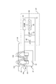
誘導性モニタリングシステム40は、プラテン内の凹部26の中に取り付けられた誘導性センサ42を含みうる。センサ42は、少なくとも部分的に凹部26の中に位置付けられた磁性コア44と、コア44の周囲に巻き付けられた少なくとも1つのコイル46とを含みうる。駆動感知回路48が、コイル46に電気接続される。駆動感知回路48は信号を生成し、その信号はコントローラ90に送信されうる。駆動感知回路48はプラテン24の外部のものとして図示されているが、駆動感知回路48の一部又は全部がプラテン24内に取り付けられることもある。回転可能プラテン内のコイル46のような構成要素を、プラテンの外部の駆動感知回路48のような構成要素に電気接続するために、回転カプラ29が使用されうる。
Inductive monitoring system 40 may include an
コア44は、背部52から平行に延びている、2つの(図1参照)、又は3つの(図2参照)突起部50を含みうる。突起部が1つしかない(背部もない)実行形態も可能である。
The core 44 may include two (see FIG. 1) or three (see FIG. 2)
図2を参照するに、回路48はコイル46にAC電流を印加し、コイル46は、コア44の2つの柱状部54aと54bとの間に磁界51を生成する。動作中、磁界56の一部分は基板100内へと延びる。
Referring to FIG. 2, a
図2は、駆動感知回路48の一例を示している。回路48は、コイル46に並列接続されたコンデンサ60を含む。コイル46とコンデンサ60は一緒になってLC共振タンクを形成しうる。動作中、電流発生装置62(例えばマージナル発振器回路に基づく電流発生装置)は、コイル46(インダクタンスLを伴う)及びコンデンサ60(キャパシタンスCを伴う)によって形成されたLCタンク回路の共振周波数で、システムを駆動させる。電流発生装置62は、正弦波振動のピークツーピーク振幅を一定の値に維持するよう設計されうる。振幅V0を伴う時間依存電圧は、整流器64を使用して整流され、フィードバック回路66に提供される。フィードバック回路66は、電流発生装置62が電圧の振幅V0を一定に保つための駆動電流を決定する。マージナル発振器回路及びフィードバック回路は、参照により組み込まれる米国特許第4,000,458号、及び第7,112,960号でより詳細に説明されている。
FIG. 2 shows an example of the
磁界56は、基板上の導電ループを通過する時に、このループ内に電流を生成する。このことは、実効インピーダンスを増大させ、ひいては、電流発生装置62が電圧の振幅V0を一定に保つために必要な駆動電流を増大させる。実効インピーダンスの増大の度合いはループの導電性に依存し、ループの導電性は、ループを画定するトレンチの中の導電性材料の深さに依存する。つまり、導電ループによる電力消失は、トレンチの中の導電性材料の深さと線形に関連する。ゆえに、電流発生装置62によって生成される駆動電流が、トレンチの中の導電性材料の深さの測定を提供する。
As the
駆動感知回路48については、他の構成も可能である。例えば、別々の駆動コイルと感知コイルがコアの周囲に巻き付けられることもあり、この駆動コイルは一定周波数で駆動されることが可能であり、感知コイルからの電流の(駆動発振器に対する)振幅又は位相が信号に使用されることが可能である。
Other configurations of the
図1を再度参照するに、一部の実行形態では、研磨ステーション20は、研磨ステーションにおける、又は、研磨ステーションの/研磨ステーション内の構成要素における温度をモニタするために、温度センサ92を含む。温度センサ92は、図1では、研磨パッド30の、及び/又はパッド30上スラリ38の温度をモニタするよう位置付けられるものとして図示されているが、基板100の温度を測定するためにキャリアヘッドの内部に位置付けられることもある。温度センサは、研磨パッド、又は基板100の露出面と直接接触している可能性がある(すなわち接触センサである)か、或いは、非接触センサ(赤外センサなど)でありうる。モニタされた温度(複数可)は、誘導性モニタリングシステムからの測定値を調節するのに使用されうる。
Referring again to FIG. 1, in some implementations, the polishing
一部の実行形態では、研磨装置は追加の研磨ステーションを含む。例えば、研磨装置は、2つ又は3つの研磨ステーションを含みうる。例えば、研磨装置は、渦電流モニタリングシステムを備えた第1研磨ステーションと、誘導性モニタリングシステムを備えた第2研磨ステーションとを含みうる。 In some implementations, the polishing apparatus includes an additional polishing station. For example, a polishing apparatus may include two or three polishing stations. For example, a polishing apparatus may include a first polishing station with an eddy current monitoring system and a second polishing station with an inductive monitoring system.
例えば、動作中、基板上の導電層のバルク研磨が第1研磨ステーションで実施されてよく、研磨は、バリア層又はパターニングされた誘電体層が露出したら停止されうる。基板は、次いで第2研磨ステーションに搬送され、トレンチがターゲット深さに到達するまで研磨されうる。 For example, in operation, bulk polishing of a conductive layer on a substrate may be performed at a first polishing station, and polishing may be stopped once the barrier layer or patterned dielectric layer is exposed. The substrate can then be transported to a second polishing station and polished until the trench reaches the target depth.
図3は、プラテン24の上面図を示している。プラテン24が回転するにつれて、センサ42が基板100の下を通り過ぎる。回路48からの信号を特定の周波数でサンプリングすることによって、回路48は、基板100の端から端までのサンプリングゾーン94のシーケンスにおける測定値を生成する。通過のたびに、サンプリングゾーン94のうちの一又は複数における測定値が選択されるか、又は結合されうる。ゆえに、複数回の通過の間ずっと、選択された又は結合された測定値が、時間で変動する値のシーケンスを提供する。加えて、センサ49が基板100の下に位置付けられない場所においては、ウエハ外測定が実施されうる。
FIG. 3 shows a top view of the
研磨ステーション20は、誘導性センサ42がいつ基板100の下方にあり、いつ基板外にあるのかを感知するために、光インタラプタのような位置センサ96も含みうる。例えば、位置センサ96は、キャリアヘッド70の反対側の定位置に装着されうる。フラッグ98は、プラテン24の周縁部に取り付けられうる。フラッグ98の取り付け場所及び長さは、フラッグ98が、センサ42がいつ基板100の下方を通過するかを位置センサ96に知らせうるように、選択される。
The polishing
代替的には、研磨ステーション20は、プラテン24の角度位置を判定するためのエンコーダを含みうる。誘導性センサは、プラテンの各回転ごとに基板の下方を通り過ぎうる。
Alternatively, polishing
コントローラ90(例えば汎用プログラマブルデジタルコンピュータ)が、誘導性モニタリングシステムから値のシーケンスを受信する。センサ42はプラテンの各回転ごとに基板の下方を通り過ぎることから、トレンチの深さについての情報が、インシトゥ(その場)に、かつ連続的なリアルタイムベースで(プラテンの1回転につき1回)、蓄積される。コントローラ90は、基板が概して薄い区域36の上にある(位置センサがそのように判定した)時にモニタリングシステムからの測定値をサンプリングするよう、プログラムされうる。研磨が進行するにつれて導電層の厚さは変化し、サンプリングされる信号も時と共に変動する。研磨中、モニタリングシステムからの測定値は出力デバイス上に表示されて、そのデバイスのオペレータが研磨動作の進行を視覚的にモニタすることを可能にしうる。
A controller 90 (eg, a general purpose programmable digital computer) receives the sequence of values from the inductive monitoring system. As the
加えて、コントローラ90は、各サンプリングゾーンの径方向位置を算出するため、及び、測定値を複数の径方向範囲ごとに分類するために、誘導性電流モニタリングシステム40からのものと基板の下の各通過によるものの両方の測定値を、複数のサンプリングゾーンごとに分けるようプログラムされうる。
In addition, the
コントローラ90は更に、キャリアヘッド70によって印加される圧力を制御する圧力機構に、キャリアヘッドの回転速度を制御するためのキャリアヘッド回転モータ76に、プラテンの回転速度を制御するためのプラテン回転モータ22に、又は、研磨パッドに供給されるスラリの組成を制御するためのスラリ分配システム39に、接続されうる。具体的には、下記で更に述べるように、測定値を径方向範囲ごとに分類した後、キャリアヘッドによって印加される研磨圧力のプロファイルを周期的又は連続的に修正するために、トレンチ深さについての情報がリアルタイムで閉ループコントローラへと送られうる。
The
図4A及び図4Bは、閉導電ループ102を有する基板100を示している。一般的に、基板は、複数の閉導電ループ102を有することになり、閉導電ループは、基板全体に均一に分散されうる。各導電ループ102は、基板内の他の相互接続配線に接続される必要はなく、基板上の自立的なフィーチャでありうる。更に、集積回路全体が完成した後であっても、導電ループ102は集積回路における自立的なフィーチャでありうる。すなわち、それらは他の相互接続配線に接続される必要がなく、集積回路のいかなる機能的回路の部分にもならない。
4A and 4B show a
導電ループは、使用される金属層に応じて約0.5〜10umのライン幅W(図5参照)を有しうる。導電ループ102は、その層内の他の相互接続配線と同じ深さを有する。
The conductive loop may have a line width W (see FIG. 5) of about 0.5-10 um depending on the metal layer used. The
一部の実行形態では、閉導電ループ102はダイ104を取り囲んでいる。例えば、閉導電ループは、ダイ104間のスクライブライン領域106内に配置されうる。一部の実行形態では、閉導電ループ102は、スクライブライン領域106内に配置されるが、ダイ104を取り囲んでいない。代替的には、閉導電ループ102は、ダイの中に配置されうる。この場合、集積回路によって使用されるがループ102の中に配置されるいかなる回路との電気接続も、別の導電層内でループ102の上又は下を通る導電ラインを経由することが必要になるであろう。
In some implementations, closed
図4Aに示すように、単一ウエハ100は、典型的には、複数のダイ104を伴って製造される。一部の実行形態では、各ダイ104が、それに関連付けられた導電ループ102を有する。例えば、各ダイ104が特有の導電ループによって囲まれうるか、導電ループが各ダイ104の中に配置されうるか、又は、導電ループがスクライブライン領域内に各ダイ104と隣接して位置付けられうる。各ダイは複数の導電ループを有してよく、導電ループは同一のサイズ、又は種々のサイズを有しうる。最終的に、ウエハはダイシングされて、個別のダイに分離される。
As shown in FIG. 4A, a
図4A及び図4Bではループは概して長方形のものとして示されているが、それが必要なわけではない。ループは、単純なn角形などの、随意の単純な(すなわち非自己干渉性の)形状である可能性がある。ループは、一又は複数の湾曲したセグメントも有しうる。 Although the loop is shown in FIGS. 4A and 4B as generally rectangular, it is not required. The loop may be of any simple (ie, non-self-interfering) shape, such as a simple n-gon. The loop may also have one or more curved segments.
誘導性モニタリングシステム40からの信号の強度は、センサ42と比較しての、詳細には、突起部50の水平寸法、及びコア44からループ102までの距離と比較しての、導電ループ102のサイズに依存することになる。導電ループを通じての電力消失は、ループを通る磁気フラックスとループの電気抵抗の両方によって決まる。一方では、導電ループが小さくなるほど、ループを通過する磁気フラックスは小さくなり、信号は弱くなる。他方では、導電ループが大きすぎると、柱状部の1つから出現する磁界ラインは、ループのエリア内に留まったまま湾曲して他の柱状部に戻ることになり、それによって、ループを通る総磁気フラックスは再び減少する。加えて、ループの電気抵抗は、ループの合計長さに対して線形に増大する。このことは、一定のサイズを有するセンサに関して、電力消失の低減、ひいては信号の衰えをもたらす。一般的に、ループのサイズは、コア44の突起部50のうちの1つのサイズに概して合致するはずである。例えば、導電ループ102の横方向寸法Lは、コア44の突起部50のうちの1つの横方向寸法のおよそ1〜2倍になるはずである。
The strength of the signal from the inductive monitoring system 40 is greater than that of the
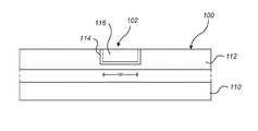
図5を参照するに、閉導電ループ102は、導電層内の他の導電フィーチャが製造されるのと同時に製造される。詳細には、トレンチは、例えばエッチングによって、ウエハ110上に堆積された誘電体層112内に形成される。誘電体層112は、例えば低誘電率層やキャッピング層などの層のスタックでありうる。薄いバリア層114が、堆積されて、トレンチの内部及び誘電体層112の上面をコーティングしうる。次いで、導電性材料116が、堆積されてトレンチを充填しうると共に、誘電体層112の上面を覆う。導電性材料は、銅又はコバルトなどの金属でありうる。バリア層は、チタン、窒化チタン、又は窒化タンタルでありうる。
Referring to FIG. 5, the closed
導電性材料116は次いで、誘電体層114の上面を露出させるために削ぎ落とされる。基板が1図4Aに示す状態に到達するのはこの時点である。基板100の研磨は、トレンチの中の導電性材料116がターゲット深さに到達するまで継続されうる。研磨ステップのこの部分において、トレンチの深さは、誘導性モニタリングシステムを使用してモニタされうる。トレンチ深さを減少させるための研磨は、誘電体層114の上面を露出させるために使用されるのと同じプラテンで実施されうる。
The
導電ループ102はその層内の他の導電性構成要素と同じプロセスで製造されることから、導電ループ102のトレンチは、集積回路の回路を提供することになるダイ内のトレンチと同じ深さを有するはずである。ゆえに、導電ループ102の厚さのモニタリングは、他の導電性フィーチャの厚さのモニタリングとしても合理的に信頼されうる。
Because the
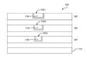
多くの基板においては、基板上に形成された、金属フィーチャを有する多重層が存在する。これらの層は時にM1、M2などと称され、M1は、半導体ウエハに最も近接した金属層である。図6を参照するに、多重層を備えた基板が研磨されている時に、各層内に導電ループが形成されうる。例えば、導電ループ102a、102b、102cが、金属層M1、M2、M3の中にそれぞれ形成されうる。一部の実行形態では、2つの異なる層内の導電ループは実質的に位置合わせされる。例えば、導電ループ102bは導電ループ102aの直上にある。
In many substrates, there are multiple layers with metal features formed on the substrate. These layers are sometimes referred to as M1, M2, etc., where M1 is the metal layer closest to the semiconductor wafer. Referring to FIG. 6, when a substrate having multiple layers is being polished, conductive loops may be formed in each layer. For example,
下の方の層内の導電ループが、測定される信号に影響を与え、結果的に、最外層におけるトレンチ深さのモニタリング中にノイズの発生源として作用することが、問題になる可能性がある。一部の実行形態では、層が基板から遠くなるほど、導電ループが幅広くなる。例えば、M3内の導電ループ102cは、M2内の導電ループ102bよりも幅広くなってよく、M2内の導電ループ102bは、M1内の導電ループ102aよりも幅広くなりうる。対称的に、集積回路の導電性相互接続部を提供するラインは、各層において同一の幅を有しうる。
It can be problematic that conductive loops in the lower layers affect the signal being measured and consequently act as sources of noise during trench depth monitoring in the outermost layer. is there. In some implementations, the further the layer is from the substrate, the wider the conductive loop. For example,
ループの幅が増大することにより、ループの抵抗は低くなる。その結果として、各層内のループからの信号の強度はだんだん強くなる。例えば、導電ループ102cからの信号の強度は導電ループ102bからの信号の強度よりも強くなり、導電ループ102bからの信号の強度は導電ループ102aからの信号の強度よりも強くなりうる。信号強度は各層ごとに増大することから、信号対ノイズ比及び最外層におけるトレンチ深さのモニタリングの信頼性に対する、下の方の層内の導電ループによって生じるノイズの影響は、少なくなる。
As the width of the loop increases, the resistance of the loop decreases. As a result, the strength of the signals from the loops in each layer becomes progressively stronger. For example, the signal strength from the
オプションでは、各導電ループは、直下の層内の導電ループに電気接続されうる。例えば、導電ループ102cは導電ループ102bに電気接続されてよく、導電ループ102bは導電ループ102aに電気接続されうる。
Optionally, each conductive loop can be electrically connected to a conductive loop in the layer immediately below. For example,
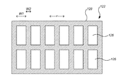
図7を参照するに、一部の実行形態では、単一の導電ループ102がマルチループ構造物122に置換される。構造物122は、導電ライン128によって分離された複数の開口126を有する。開口126は均一に離間しうる。一部の実行形態では、構造物122は、金属のリングライン内に誘電体スリットを挿入することによって形成される。マルチループ構造物122の複合構造は、ダイ104において集積回路の部分を形成することになるクリティカルデバイスのトレンチ又は相互接続ラインのCMP挙動に近似又は類似した、CMP挙動を有するよう設計されうる。
Referring to FIG. 7, in some implementations, a single
ライン128が占める面積に対する開口126が占める面積の比率は、隣接ダイにおけるデバイスパターンのパターン密度に合致するよう選択されうる。例えば、隣接ダイ内のデバイスパターンが50%のパターン密度を有する場合、総面積に対するラインが占める面積の比率は0.5でありうる。このことは、金属ラインが、CMP動作に対して、ダイ内のパターンと類似した反応を有することを可能にする。
The ratio of the area occupied by the
図1から図3を再度参照するに、上述したように、磁界56は、基板100上の導電ループ102を通過する時にループ102内に電流を生成し、そのことが、誘導性モニタリングシステムからの信号の強度の変化をもたらす。しかし、センサ42は基板に対して移動し、ループは基板全体に分散されることから、センサ42は、時にループがない領域の上方に位置することになり、ループ102を断続的にしか通り過ぎないかもしれない。その結果として、誘導性モニタリングシステムからの信号は、ループからの影響を断続的にしか記録しないことになる。
Referring again to FIGS. 1-3, as described above, the
図8は、基板100の端から端までのセンサ42の単一の通過によるサンプル信号130のグラフを示している。このグラフでは、水平軸は基板の中心からの距離を表し、垂直軸は信号強度を(任意単位で)表している。信号130は、信号強度が低い初期部分132を含む。部分132は、センサがキャリアヘッドの下になく、そのため信号を生成するものが何もない時間を表しうる。この部分に続くのは、信号強度が中程度の部分134である。この部分134は、センサが保持リングの下にあり、そのため、キャリア又は保持リングにおける金属部分がいくらかの信号を生成する可能性がある時間を表しうる。
FIG. 8 shows a graph of the sampled
次いで、多数の個別の山部(spike)140が谷部(valley)142によって分離されている、著しい「ノイズ」を有するように見える部分136が続く。一般的に、部分136の間ずっと、信号強度が最小値144未満に落ちることはない。何らかの特定の理論に制限されるものではないが、山部140は、センサ42がループの下に位置している時間を表してよく、谷部142は、センサがループを有さない領域の下に位置している時間を表しうる。
This is followed by a
山部140の信号強度はトレンチの深さを表すことから、信号は、外来の背景信号及びノイズを取り除くよう処理される必要がある。信号処理は、コントローラ90によって実施されうる。
Since the signal strength of the
一般的には、信号ウインドウが選択される。信号ウインドウは、時間の、センサが基板の端から端まで、又は基板上の一径方向ゾーンをスキャンしている部分を表しうる。オプションでは、信号は最初、基板上の導電ループによって生成されない信号のDC部分を取り除くために、高パスフィルタに通されうる。基準値(reference value)を生成するために、センサがキャリアヘッドの下にない時の信号強度が測定される。この基準値は、例えば信号ウインドウにおいて、センサがキャリアヘッドの下にある間に測定された信号から減算される。このことは、例えば化学的又は熱的な環境変化による、基板の研磨動作中の信号ドリフトを補償しうる。 Generally, a signal window is selected. The signal window may represent a portion of time, where the sensor is scanning across the substrate or across a radial zone on the substrate. Optionally, the signal may first be high-pass filtered to remove the DC portion of the signal that is not generated by a conductive loop on the substrate. In order to generate a reference value, the signal strength when the sensor is not under the carrier head is measured. This reference value is subtracted from the signal measured while the sensor is under the carrier head, for example in a signal window. This may compensate for signal drift during the polishing operation of the substrate due to, for example, chemical or thermal environmental changes.
一実行形態では、信号130の強度は、平均信号値を生成するために、信号ウインドウ全体を通じて平均化される。この平均値は出力値として使用されうる。この技法は、導電ループが基板中に均一かつ高密度に分散されている場合に、適切でありうる。
In one implementation, the intensity of
別の実行形態では、信号ウインドウ内の個別のピーク140が識別される。各ピーク140の最大信号強度が判定される。ピークツーフロア(peak−to−floor)信号値の組を生成するために、フロアの信号強度、例えばピーク間の谷部領域の平均値が、各ピークの信号強度から減算される。信号ウインドウからのこのピークツーフロア信号値の組は、平均ピークツーフロア信号値を生成するために平均化されうる。この平均ピークツーフロア信号値は、出力値として使用されうる。この技法は、ピークがあまりなくフロア値の変動がない信号に対して、例えば、導電ループが、比較的低密度に分散されており、かつ、各ダイの中に配置されている場合に、適切でありうる。
In another implementation,
別の実行形態では、信号ウインドウ内の個別のピーク140が識別される。各ピーク140の最大信号強度が判定される。信号ウインドウ内のピークの信号強度は、平均ピーク値を生成するために平均化されうる。この平均ピーク信号値は出力値として使用されうる。この技法は、ピークがあまりなく、かつ不均一な信号に対して、例えば、各ダイの中に種々のサイズの導電ループが存在し、比較的低密度に分散されている場合に、適切でありうる。
In another implementation,
上記の実行形態の各々においては、通過毎に信号ウインドウに対して1つの出力値が存在することから、研磨が進行するにつれて、この出力値が値のシーケンスを生成し、その値のシーケンスは、終点検出又は閉ループの研磨速度の制御に使用されうる。 In each of the above implementations, since there is one output value for the signal window per pass, as polishing proceeds, this output value produces a sequence of values, which sequence is: It can be used for endpoint detection or for controlling the closed loop polishing rate.
「ピーク(peaks)」とは、下方のベースライン信号から上に向かう山部の尖り、又は、上方のベースライン信号から下に向かう谷部の尖りでありうることを、理解すべきである。後者の場合、「最大信号強度」は、実際にはピークの最低点となる。 It should be understood that "peaks" may be the peaks of a ridge going upwards from a lower baseline signal, or the valleys of a valley going downwards from an upper baseline signal. In the latter case, the "maximum signal strength" is actually the lowest point of the peak.
図9は、デバイス基板100の研磨中に誘導性モニタリングシステムによって生成された出力値の150のグラフの一例である。このグラフでは、水平軸は時間を表し、垂直軸は出力値を表している。一部の実行形態では、出力値は、ルックアップテーブルを使用するなどして、値150を提供する厚さの値に変換されうる。
FIG. 9 is an example of a graph of 150 output values generated by the inductive monitoring system during polishing of the
一部の実行形態では、第2のスペクトル特徴の現行値がターゲット値152に到達する時が、終点と見なされうる。ターゲット値152は、トレンチがターゲット深さを有する時の誘導性モニタリングシステムの出力を表す。
In some implementations, when the current value of the second spectral feature reaches the
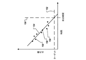
一部の実行形態では、例えばロバストなラインフィットを使用して、関数154が出力値150にフィットさせられる。関数154は、研磨終点時間を決定するために使用されうる。一部の実行形態では、関数は時間の線形関数である。一部の実行形態では、関数154がターゲット値152と等しくなる時点が、終点時間156を提供する。
In some implementations, the
図10は、基板100上の2つの異なるゾーンに関する出力値のグラフの一例である。例えば、誘導性モニタリングシステム40は、基板100のエッジ部分寄りに位置する第1ゾーンと、基板100の中心寄りに位置する第2ゾーンとを辿りうる。第1出力値160のシーケンスは、基板100の第1ゾーンで測定されてよく、第2出力値162のシーケンスは、基板100の第2ゾーンで同様に測定されうる。
FIG. 10 is an example of a graph of output values for two different zones on the
第1関数164(例えば第1のライン)は、第1出力値160のシーケンスにフィットさせられてよく、第2関数166(例えば第2のライン)は、第2出力値162のシーケンスにフィットさせられうる。第1関数164及び第2関数166は、基板10の研磨速度の調節を決定するために使用されうる。
A first function 164 (eg, a first line) may be fitted to a sequence of
研磨中に、基板100の第1ゾーンのための第1関数を用いて、かつ、基板100の第2ゾーンのための第2関数を用いて、ターゲット値168に基づく推定終点の算出が、時間TCにおいて行われる。ターゲット値168は、トレンチがターゲット深さを有する時の誘導性モニタリングシステムの出力を表す。第1と第2のゾーンのための推定終点時間T1とT2が相違する場合(又は、推定終点時間170において第1関数と第2関数の値が相違する場合)、ゾーンのうちの少なくとも1つの研磨速度が調節されてよく、第1ゾーンと第2ゾーンは、かかる調節がなかった場合よりも同一に近い終点時間を有する。例えば、第1ゾーンが第2ゾーンよりも早くターゲット値168に到達することになる場合、第2ゾーンの研磨速度は、第2ゾーンが第1ゾーンと実質的に同時にターゲット値168に到達するように、加速されうる(ライン172で示す)。一部の実行形態では、基板の第1部分と第2部分の両方の研磨速度が、両方の部分で同時に終点に到達するように、調節される。代替的には、第1部分又は第2部分のみの研磨速度が調節されうる。
During polishing, using the first function for the first zone of the
出力値のシーケンスは出力信号を提供する。一部の実行形態では、出力信号は、関数のフィッティングに先立ってフィルタリングされうる。例えば、状況によっては、出力信号は規則的で周期的な振動を示す。このことは、何らかの特定の理論に制限されるものではないが、プラテンの回転の合間の基板配向の変化によるものであるかもしれない。この周期的な振動を補償するために、出力値のシーケンスに次のアルゴリズムが適用されうる:
処理された信号(signal)=sqrt[signal(t)*signal(t)+signal(t−Δt)*signal(t−Δt)]
ここでΔtは、振動周期の四分の一である。振動周期は、例えば、出力信号のフーリエ変換を実施すること、及び、ピーク周波数強度を決定することによって、決まりうる。
The sequence of output values provides an output signal. In some implementations, the output signal may be filtered prior to fitting the function. For example, in some situations, the output signal exhibits regular and periodic oscillations. This is not limited to any particular theory, but may be due to a change in substrate orientation between platen rotations. To compensate for this periodic oscillation, the following algorithm can be applied to the sequence of output values:
Processed signal (signal) = sqrt [signal (t) * signal (t) + signal (t−Δt) * signal (t−Δt)]
Here, Δt is a quarter of the oscillation period. The oscillation period can be determined, for example, by performing a Fourier transform of the output signal and determining the peak frequency intensity.
最初、研磨を行う前に、電流発生装置62は、基板が全く存在しなくとも、LC回路の共振周波数に調整されうる。この共振周波数は、出力信号の最大振幅をもたらす。
Initially, prior to polishing, the
図11Aに示すように、研磨動作のために、基板100は研磨パッド30と接触した状態に置かれる。基板100は、下にあるパターニングされた誘電体層112を覆っている導電層116を有する。研磨に先立ち、導電層116のバルクは最初比較的厚く、連続していることから、その抵抗は低い。その結果として、誘導性モニタリングシステム40からの磁界は、導電層内に渦電流を生成しうる。渦電流は、金属層をインピーダンス源として機能させる。このことが、導電層のバルク研磨中に基板の厚さをモニタすることを可能にする。
As shown in FIG. 11A, the
図11Bを参照するに、基板100が研磨されるにつれて、導電層116のバルク部分は薄化される。導電層116が薄化するにつれて、そのシート抵抗は増大し、金属層内の渦電流は減衰していく。一部の実行形態では、誘導性モニタリングシステム又は別のモニタリングシステムが、所定の厚さTの導電層が残って下層を覆っていると判定すると、基板は別のプラテンに移されうる。
Referring to FIG. 11B, as the
図11Cを参照するに、最終的に、導電層116のバルク部分は取り除かれ、バリア層114が露出し、パターニングされた誘電体層112間のトレンチの中に導電性材料116が残されて、デバイスの相互接続部108及びループ導体102を提供する。一部の実行形態では、誘導性モニタリングシステム、又は、光学モニタリングシステムのような別のモニタリングシステムが、バリア層が露出したと判定すると、基板は別のプラテンに移されうる。
Referring to FIG. 11C, ultimately, the bulk portion of the
図11Dを参照するに、バリア層114を取り除き、パターニングされた誘電体層112の上面を露出させるために、研磨が継続される。トレンチの中の導電性材料116の深さも減少する。一部の実行形態では、誘導性モニタリングシステム、又は、光学モニタリングシステムのような別のモニタリングシステムが、バリア層が露出したと判定すると、基板は別のプラテンに移されうる。
Referring to FIG. 11D, polishing is continued to remove the
同一のプラテンにおいて、基板に導電層のバルク研磨と誘電体層の薄化の両方が行われる場合、次いで、バリア層114、又は誘電体層112の上面のいずれかが露出した後に、誘導性モニタリングシステム40のモードは、バルク厚さモニタリングモードからトレンチ深さモニタリングモードへと切り替えられる。一般的に、トレンチ深さモニタリングモードにおいては、値のシーケンスを生成するために、導電ループから生じる信号のピークは検出され、信号全体から抽出される必要がある。対称的に、バルク厚さモニタリングモードでは、かかるピークが予測されることも抽出されることもなく、バルク導電層の厚さをモニタするために生信号が平均化されうる。
If the substrate undergoes both bulk polishing of the conductive layer and thinning of the dielectric layer on the same platen, then the inductive monitoring is performed after either the
図11Eを参照するに、誘導性モニタリングシステム40がトレンチ深さモニタリングモードの状態で、基板が研磨される。このことは、誘電体層112を薄化させると共に、トレンチの中の導電性相互接続部116’の深さを減少させる。上述のように、誘導性モニタリングシステム40からの信号は、研磨終点を検出し、かつ、トレンチがターゲット深さDに到達したら研磨を停止し、かつ/又は、基板の種々の部分の研磨速度を修正して、研磨均一性を向上させるために使用されうる。
Referring to FIG. 11E, the substrate is polished with the inductive monitoring system 40 in the trench depth monitoring mode. This thins the
一部の実行形態では、バルク研磨をモニタするために誘導性モニタリングシステムを使用するのではなく、研磨ステーションが、別個の渦電流モニタリングシステムを含む。一部の実行形態では、研磨ステーションは光学モニタリングシステムを含む。光学モニタリングシステムは、バリア層又はパターニングされた誘電体層の露出を検出するために使用されうる。バリア層又はパターニングされた誘電体層の露出の検出は、誘導性モニタリングシステムでのモニタリングを始動させるために、又は、誘導性モニタリングシステムの、バルク厚さモニタリングモードからトレンチ深さモニタリングモードへの切り替えを始動させるために、使用されうる。 In some implementations, rather than using an inductive monitoring system to monitor bulk polishing, the polishing station includes a separate eddy current monitoring system. In some implementations, the polishing station includes an optical monitoring system. Optical monitoring systems can be used to detect the exposure of barrier layers or patterned dielectric layers. Detection of the exposure of the barrier layer or the patterned dielectric layer can be used to initiate monitoring with an inductive monitoring system or to switch the inductive monitoring system from a bulk thickness monitoring mode to a trench depth monitoring mode. Can be used to start
一部の実行形態では、研磨の後に、基板はバフ研磨ステップを経る。 In some implementations, after polishing, the substrate undergoes a buff polishing step.
誘導性モニタリングシステムは、多種多様な研磨システムにおいて使用されうる。研磨パッド又はキャリアヘッドのいずれか、或いはその両方は、移動して、研磨面と基板との相対運動を起こしうる。研磨パッドは、プラテン、供給ローラと回収ローラとの間に延びるテープ、又は連続ベルトに固定された、円形(又は他の何らかの形状)のパッドでありうる。研磨パッドは、プラテンに取り付けられうるか、研磨動作の合間にプラテン上で漸進的に送られうるか、又は、研磨中にプラテン上で連続的に駆動されうる。パッドは研磨中にプラテンに固定されうるか、又は、研磨中にプラテンと研磨パッドとの間には流体軸受が存在しうる。研磨パッドは、標準的な(例えば充填材を伴う又は伴わないポリウレタンの)粗パッド、軟性パッド、又は固定砥粒パッドでありうる。 Inductive monitoring systems can be used in a wide variety of polishing systems. Either the polishing pad or the carrier head, or both, can move to cause relative movement between the polishing surface and the substrate. The polishing pad can be a circular (or some other shape) pad fixed to a platen, tape extending between a supply roller and a collection roller, or a continuous belt. The polishing pad may be attached to the platen, may be incrementally fed on the platen between polishing operations, or may be continuously driven on the platen during polishing. The pad may be fixed to the platen during polishing, or there may be a hydrodynamic bearing between the platen and the polishing pad during polishing. The polishing pad can be a standard coarse pad (eg, of polyurethane with or without filler), a soft pad, or a fixed abrasive pad.
加えて、上述の説明は研磨中のモニタリングに注目したものであるが、これらの技法をインラインモニタリングシステムに適用することも可能であろう。例えば、研磨ステーションがファクトリインターフェース内、又はファクトリインターフェースに取り付けられたモジュール内などに位置付けられる前に、静止センサが研磨装置の一区域内に位置付けられることも可能である。基板の搬送に関与するロボットが、センサを通過するように基板を移動させることも可能である代替的には、基板は、ファクトリインターフェース内、又は要素インターフェースに取り付けられたモジュール内でスタンド上に位置付けられることもあり、基板が静止している間にアクチュエータが基板の端から端までセンサを移動させることも可能である。いずれの場合にも、基板の端から端までで得られる一連の測定値は、インシトゥ(その場)のモニタリングシステムのセンサの、基板の端から端までの単一のスキャンに等しくなってよく、上述のように処理されて、トレンチの深さの一測定値を生成しうる。 In addition, although the above description has focused on monitoring during polishing, these techniques could be applied to in-line monitoring systems. For example, a static sensor may be positioned within an area of the polishing apparatus before the polishing station is positioned, such as in the factory interface or in a module attached to the factory interface. It is also possible for the robot involved in transporting the substrate to move the substrate past the sensor.Alternatively, the substrate is positioned on a stand in the factory interface or in a module attached to the element interface In some cases, the actuator may move the sensor across the substrate while the substrate is stationary. In each case, the series of measurements taken across the board may be equal to a single scan of the sensor of the in-situ monitoring system across the board, Processed as described above, it may produce a measure of trench depth.
本発明の実施形態、及びこの明細書で説明されている機能的動作の全ては、この明細書で開示されている構造的手段及びその構造的同等物、又はそれらの組み合わせを含め、デジタル電子回路において、或いは、コンピュータのソフトウェア、ファームウェア、又はハードウェアにおいて、実装されうる。本発明の実施形態は、一又は複数のコンピュータプログラム製品、すなわち、プログラマブルプロセッサ、コンピュータ、或いは複数のプロセッサ又はコンピュータなどのデータ処理装置による実行のため、或いは、かかるデータ処理装置の動作を制御するために、非一過性の機械可読記憶媒体又は被伝播信号等の情報担体において有形に具現化された、一又は複数のコンピュータプログラムとして、実装されうる。コンピュータプログラム(プログラム、ソフトウェア、ソフトウェアアプリケーション又はコードとしても知られている)は、コンパイル型言語又はインタプリタ型言語を含む任意の形態のプログラミング言語で書かれてよく、かつ、スタンドアローンプログラムとして、又はモジュール、コンポーネント、サブルーチン、又はコンピューティング環境での使用に適するその他のユニットとしてを含め、任意の形態でデプロイされうる。1つのコンピュータプログラムは、必ずしも1つのファイルに対応していない。プログラムは、他のプログラム又はデータを保持するファイルの一部分に、当該プログラム専用の単一のファイルに、又は、複数の連携ファイル(例えば、一又は複数のモジュール、サブプログラム、又はコードの部分を保存するファイル)に保存されうる。コンピュータプログラムは、1つのコンピュータ上で、或いは、1つのサイトにある、又は複数のサイトにわたって分散され、かつ通信ネットワークによって相互接続された複数のコンピュータ上で、実行されるようデプロイされうる。 Embodiments of the present invention, and all of the functional operations described herein, include digital electronic circuits, including the structural means disclosed herein and their structural equivalents, or combinations thereof. Or in software, firmware, or hardware of a computer. Embodiments of the present invention may be used to execute or control the operation of one or more computer program products, i.e., a programmable processor, a computer, or a plurality of processors or data processing devices such as computers. In addition, it can be implemented as one or more computer programs tangibly embodied in an information carrier such as a non-transitory machine-readable storage medium or a propagated signal. A computer program (also known as a program, software, software application or code) may be written in any form of programming language, including compiled or interpreted languages, and as a stand-alone program or as a module , Components, subroutines, or other units suitable for use in a computing environment. One computer program does not necessarily correspond to one file. A program may be a part of a file that holds other programs or data, a single file dedicated to the program, or a plurality of linked files (for example, storing one or more modules, subprograms, or code portions). File). The computer program may be deployed to be executed on one computer or on multiple computers at one site or distributed across multiple sites and interconnected by a communication network.
この明細書で説明されているプロセス及び論理フローは、一又は複数のプログラマブルプロセッサによって実施されてよく、このプログラマブルプロセッサは、入力データに対して動作し、かつ出力を生成することによって諸機能を果たすために、一又は複数のコンピュータプログラムを実行する。プロセス及び論理フローは、FPGA(フィールドプログラマブルゲートアレイ)又はASIC(特定用途向け集積回路)などの特殊用途論理回路によって実施されてもよく、装置が、かかる特殊用途論理回路として実装されることも可能である。 The processes and logic flows described herein may be implemented by one or more programmable processors, which operate on input data and perform functions by generating outputs. For this purpose, one or more computer programs are executed. The processes and logic flows may be implemented by special purpose logic circuits such as FPGAs (Field Programmable Gate Arrays) or ASICs (Application Specific Integrated Circuits), and the device may be implemented as such special purpose logic circuits It is.
本発明の複数の実施形態を説明してきた。それでもなお、本発明の本質及び範囲から逸脱することなく様々な修正が行われうることを、理解されたい。従って、その他の実施形態も下記の特許請求の範囲内にある。
A number of embodiments of the invention have been described. Nevertheless, it will be understood that various modifications may be made without departing from the spirit and scope of the invention. Thus, other embodiments are also within the following claims.
Claims (15)
複数の導電性相互接続部を備えた層を有する集積回路の製造において、前記集積回路の前記層を提供するために、基板の層を研磨することであって、前記基板の前記層は、前記導電性相互接続部を提供するための導電ラインを含み、前記基板の前記層は、トレンチの中の導電性材料で形成された閉導電ループを含む、研磨すること、
誘導性モニタリングシステムを使用して、前記トレンチの中の前記導電性材料の深さをモニタすることであって、前記モニタすることは、前記閉導電ループを断続的に通過する磁界を生成することを含む、モニタすることと、信号を生成すること、及び、
前記信号から、前記導電性材料の深さを経時的に表す値のシーケンスを経時的に抽出すること、並びに、
前記導電性材料の深さがターゲット深さに到達したと、前記値のシーケンスから判定することによって、研磨終点を検出すること、又は、
前記層の研磨中にキャリアヘッドによって前記基板に印加される少なくとも1つの圧力を前記値のシーケンスに基づいて調節し、前記基板上の種々のゾーンが、かかる調節がなかった場合よりも同一に近い終点時間を有すること、のうちの少なくとも1つを含む、方法。 A method of chemically mechanically polishing a substrate, comprising:
In the manufacture of an integrated circuit having a layer with a plurality of conductive interconnects, polishing a layer of a substrate to provide the layer of the integrated circuit, the layer of the substrate comprising: Polishing, including conductive lines for providing conductive interconnects, wherein the layer of the substrate includes a closed conductive loop formed of a conductive material in a trench;
Monitoring the depth of the conductive material in the trench using an inductive monitoring system, wherein the monitoring generates a magnetic field that intermittently passes through the closed conductive loop. Monitoring and generating a signal; and
From the signal, and over time extracting child sequence over time represents the value of the depth of the conductive material, and,
When the depth of the conductive material reaches the target depth, by determining from the sequence of the values, to detect the polishing end point, or
Adjusting at least one pressure applied to the substrate by the carrier head during polishing of the layer based on the sequence of values, wherein various zones on the substrate are closer to the same than without such adjustments. Having at least one end time.
研磨を受けている基板の層内のトレンチの中の導電性材料で形成された閉導電ループに断続的に磁界を通過させることによって生成された信号を、誘導性モニタリングシステムから受信すること、及び、
前記信号から、前記導電性材料の深さを経時的に表す値のシーケンスを経時的に抽出すること、並びに、
前記導電性材料の深さがターゲット深さに到達したと、前記値のシーケンスから判定することによって、研磨終点を検出すること、又は、
研磨ステーションにおける前記層の研磨中にキャリアヘッドによって前記基板に印加される少なくとも1つの圧力が、前記値のシーケンスに基づいて調節されるようにし、前記基板上の種々のゾーンが、かかる調節がなかった場合よりも同一に近い終点時間を有すること、のうちの少なくとも1つを含む、コンピュータプログラム製品。 A computer program product encoded on a non-transitory computer storage medium and operable to cause a processor to perform an operation for controlling a polishing operation, wherein the operation comprises:
Receiving from an inductive monitoring system a signal generated by intermittently passing a magnetic field through a closed conductive loop formed of conductive material in a trench in a layer of the substrate being polished; and ,
From the signal, and over time extracting child sequence over time represents the value of the depth of the conductive material, and,
When the depth of the conductive material reaches the target depth, by determining from the sequence of the values, to detect the polishing end point, or
At least one pressure applied to the substrate by the carrier head during polishing of the layer at a polishing station is adjusted based on the sequence of values, and the various zones on the substrate are free of such adjustments. Having at least one endpoint time that is closer than the same.
研磨パッドを支持する表面を有するプラテンと、
基板上の層が前記研磨パッドと接触するように前記基板を保持するためのキャリアヘッドと、
前記基板の前記層内の閉導電ループを断続的に通過する磁界を生成することによって、前記基板上の前記層内のトレンチの中の導電性材料の深さをモニタするための、誘導性センサと、
誘導性モニタリングシステムから信号を受信し、かつ、前記信号から、値のシーケンスを抽出するよう構成されたコントローラであって、前記値のシーケンスは、前記閉導電ループを提供する前記層内のトレンチの中の導電性材料の深さを表し、前記コントローラは、前記導電性材料の深さはターゲット深さに到達したと前記値のシーケンスから判定することによって、研磨終点を検出すること、又は、前記層の研磨中に前記キャリアヘッドによって前記基板に印加される少なくとも1つの圧力を、前記値のシーケンスに基づいて調節し、前記基板上の種々のゾーンは、かかる調節がなかった場合よりも同一に近い終点時間を有すること、のうちの少なくとも1つを実施するよう構成されている、コントローラを備える、装置。 An apparatus for chemical mechanical polishing, wherein
A platen having a surface that supports the polishing pad;
A carrier head for holding the substrate such that a layer on the substrate is in contact with the polishing pad;
An inductive sensor for monitoring the depth of conductive material in trenches in the layer on the substrate by generating a magnetic field that intermittently passes through a closed conductive loop in the layer of the substrate. When,
A controller configured to receive a signal from an inductive monitoring system and to extract a sequence of values from the signal, wherein the sequence of values comprises a trench in the layer providing the closed conductive loop. Representing the depth of the conductive material therein, wherein the controller detects a polishing endpoint by determining from the sequence of values that the depth of the conductive material has reached a target depth, or At least one pressure applied by the carrier head to the substrate during polishing of a layer is adjusted based on the sequence of values, and various zones on the substrate are more identical than without such adjustment. An apparatus comprising a controller configured to perform at least one of: having a near endpoint time.
Applications Claiming Priority (3)
| Application Number | Priority Date | Filing Date | Title |
|---|---|---|---|
| US14/312,503 US9754846B2 (en) | 2014-06-23 | 2014-06-23 | Inductive monitoring of conductive trench depth |
| US14/312,503 | 2014-06-23 | ||
| PCT/US2015/036520 WO2015200101A1 (en) | 2014-06-23 | 2015-06-18 | Inductive monitoring of conductive trench depth |
Publications (3)
| Publication Number | Publication Date |
|---|---|
| JP2017520124A JP2017520124A (en) | 2017-07-20 |
| JP2017520124A5 JP2017520124A5 (en) | 2018-07-26 |
| JP6640754B2 true JP6640754B2 (en) | 2020-02-05 |
Family
ID=54870327
Family Applications (1)
| Application Number | Title | Priority Date | Filing Date |
|---|---|---|---|
| JP2016574899A Active JP6640754B2 (en) | 2014-06-23 | 2015-06-18 | Inductive monitoring of conductive trench depth |
Country Status (6)
| Country | Link |
|---|---|
| US (3) | US9754846B2 (en) |
| JP (1) | JP6640754B2 (en) |
| KR (1) | KR102383708B1 (en) |
| CN (2) | CN106463380B (en) |
| TW (2) | TWI701733B (en) |
| WO (1) | WO2015200101A1 (en) |
Families Citing this family (17)
| Publication number | Priority date | Publication date | Assignee | Title |
|---|---|---|---|---|
| US9754846B2 (en) * | 2014-06-23 | 2017-09-05 | Applied Materials, Inc. | Inductive monitoring of conductive trench depth |
| TW201822953A (en) * | 2016-09-16 | 2018-07-01 | 美商應用材料股份有限公司 | Overpolishing based on electromagnetic inductive monitoring of trench depth |
| US10427272B2 (en) * | 2016-09-21 | 2019-10-01 | Applied Materials, Inc. | Endpoint detection with compensation for filtering |
| TWI816620B (en) * | 2017-04-21 | 2023-09-21 | 美商應用材料股份有限公司 | Polishing apparatus using neural network for monitoring |
| TWI783037B (en) * | 2017-09-25 | 2022-11-11 | 美商應用材料股份有限公司 | Semiconductor fabrication using machine learning approach to generating process control parameters |
| TWI825075B (en) | 2018-04-03 | 2023-12-11 | 美商應用材料股份有限公司 | Polishing apparatus, polishing system, method, and computer storage medium using machine learning and compensation for pad thickness |
| JP7083279B2 (en) | 2018-06-22 | 2022-06-10 | 株式会社荏原製作所 | How to identify the trajectory of the eddy current sensor, how to calculate the progress of polishing the substrate, how to stop the operation of the substrate polishing device and how to equalize the progress of polishing the substrate, to execute these methods. The program and the non-transient recording medium on which the program is recorded |
| US11056351B2 (en) * | 2018-08-31 | 2021-07-06 | Synaptics Incorporated | Process monitor for wafer thinning |
| US11251096B2 (en) * | 2018-09-05 | 2022-02-15 | Micron Technology, Inc. | Wafer registration and overlay measurement systems and related methods |
| US11009798B2 (en) | 2018-09-05 | 2021-05-18 | Micron Technology, Inc. | Wafer alignment markers, systems, and related methods |
| JP7291558B2 (en) * | 2019-07-03 | 2023-06-15 | 株式会社荏原製作所 | Eddy current sensor |
| JP7341022B2 (en) | 2019-10-03 | 2023-09-08 | 株式会社荏原製作所 | Substrate polishing equipment and film thickness map creation method |
| JP7507576B2 (en) | 2020-03-17 | 2024-06-28 | 株式会社東京精密 | Grinding Equipment |
| JP2023517449A (en) | 2020-05-14 | 2023-04-26 | アプライド マテリアルズ インコーポレイテッド | Techniques and polishing systems for training neural networks for use in in-situ monitoring during polishing |
| TWI810069B (en) | 2020-06-08 | 2023-07-21 | 美商應用材料股份有限公司 | System, method and computer porgram product for profile control during polishing of a stack of adjacent conductive layers |
| CN115038549B (en) | 2020-06-24 | 2024-03-12 | 应用材料公司 | Substrate layer thickness determination using polishing pad wear compensation |
| WO2022186993A1 (en) * | 2021-03-03 | 2022-09-09 | Applied Materials, Inc. | Motor torque endpoint during polishing with spatial resolution |
Family Cites Families (36)
| Publication number | Priority date | Publication date | Assignee | Title |
|---|---|---|---|---|
| US4000458A (en) | 1975-08-21 | 1976-12-28 | Bell Telephone Laboratories, Incorporated | Method for the noncontacting measurement of the electrical conductivity of a lamella |
| US6268618B1 (en) * | 1997-05-08 | 2001-07-31 | Showa Denko K.K. | Electrode for light-emitting semiconductor devices and method of producing the electrode |
| US6741076B2 (en) | 2000-04-07 | 2004-05-25 | Cuong Duy Le | Eddy current measuring system for monitoring and controlling a CMP process |
| US6966816B2 (en) * | 2001-05-02 | 2005-11-22 | Applied Materials, Inc. | Integrated endpoint detection system with optical and eddy current monitoring |
| US6716644B2 (en) * | 2002-05-17 | 2004-04-06 | Micron Technology, Inc. | Method for forming MRAM bit having a bottom sense layer utilizing electroless plating |
| US6848166B2 (en) | 2002-05-28 | 2005-02-01 | Hitachi Global Storage Technologies | Method of protecting the pole piece of a magnetic head during the ion mill patterning of the yoke |
| US20040206621A1 (en) * | 2002-06-11 | 2004-10-21 | Hongwen Li | Integrated equipment set for forming a low K dielectric interconnect on a substrate |
| US7128803B2 (en) | 2002-06-28 | 2006-10-31 | Lam Research Corporation | Integration of sensor based metrology into semiconductor processing tools |
| US6858531B1 (en) * | 2002-07-12 | 2005-02-22 | Lsi Logic Corporation | Electro chemical mechanical polishing method |
| JP2005011977A (en) * | 2003-06-18 | 2005-01-13 | Ebara Corp | Device and method for substrate polishing |
| US7112960B2 (en) | 2003-07-31 | 2006-09-26 | Applied Materials, Inc. | Eddy current system for in-situ profile measurement |
| US7097537B1 (en) * | 2003-08-18 | 2006-08-29 | Applied Materials, Inc. | Determination of position of sensor measurements during polishing |
| TWI352645B (en) * | 2004-05-28 | 2011-11-21 | Ebara Corp | Apparatus for inspecting and polishing substrate r |
| US7777338B2 (en) | 2004-09-13 | 2010-08-17 | Taiwan Semiconductor Manufacturing Co., Ltd. | Seal ring structure for integrated circuit chips |
| KR100660916B1 (en) * | 2006-02-09 | 2006-12-26 | 삼성전자주식회사 | Method of fabricating a semiconductor device including planarizing a conductive layer using parameters of pattern density and depth of trenches |
| JP4159594B1 (en) | 2007-05-21 | 2008-10-01 | 株式会社東京精密 | Method and apparatus for predicting and detecting the end of polishing |
| TWI444248B (en) * | 2007-08-15 | 2014-07-11 | 羅門哈斯電子材料Cmp控股公司 | Chemical mechanical polishing method |
| US7821257B2 (en) * | 2007-09-03 | 2010-10-26 | Tokyo Seimitsu Co., Ltd | Method and device for forecasting/detecting polishing end point and method and device for monitoring real-time film thickness |
| JP5080933B2 (en) * | 2007-10-18 | 2012-11-21 | 株式会社荏原製作所 | Polishing monitoring method and polishing apparatus |
| KR20090074970A (en) | 2008-01-03 | 2009-07-08 | 삼성전자주식회사 | Semiconductor device having guard ring |
| US8106651B2 (en) | 2008-04-17 | 2012-01-31 | Novellus Systems, Inc. | Methods and apparatuses for determining thickness of a conductive layer |
| US7960188B2 (en) | 2008-05-15 | 2011-06-14 | Ebara Corporation | Polishing method |
| US8334582B2 (en) | 2008-06-26 | 2012-12-18 | Taiwan Semiconductor Manufacturing Company, Ltd. | Protective seal ring for preventing die-saw induced stress |
| JP5611214B2 (en) * | 2008-10-16 | 2014-10-22 | アプライド マテリアルズ インコーポレイテッドApplied Materials,Incorporated | Eddy current gain compensation |
| US8628376B2 (en) | 2008-11-07 | 2014-01-14 | Applied Materials, Inc. | In-line wafer thickness sensing |
| US20110189856A1 (en) * | 2010-01-29 | 2011-08-04 | Kun Xu | High Sensitivity Real Time Profile Control Eddy Current Monitoring System |
| TW201201957A (en) | 2010-01-29 | 2012-01-16 | Applied Materials Inc | High sensitivity real time profile control eddy current monitoring system |
| US8252648B2 (en) * | 2010-06-29 | 2012-08-28 | Alpha & Omega Semiconductor, Inc. | Power MOSFET device with self-aligned integrated Schottky and its manufacturing method |
| TWI521625B (en) * | 2010-07-30 | 2016-02-11 | 應用材料股份有限公司 | Detection of layer clearing using spectral monitoring |
| TW201223702A (en) * | 2010-08-06 | 2012-06-16 | Applied Materials Inc | Techniques for matching measured spectra to reference spectra for in-situ optical monitoring |
| CN106239354A (en) * | 2010-09-30 | 2016-12-21 | 内克斯普拉纳公司 | Polishing pad for vortex flow end point determination |
| US9023667B2 (en) | 2011-04-27 | 2015-05-05 | Applied Materials, Inc. | High sensitivity eddy current monitoring system |
| US20120276662A1 (en) | 2011-04-27 | 2012-11-01 | Iravani Hassan G | Eddy current monitoring of metal features |
| US9018023B2 (en) | 2011-08-16 | 2015-04-28 | Globalfoundries Inc. | Detection of surface defects by optical inline metrology during Cu-CMP process |
| US9205527B2 (en) * | 2012-11-08 | 2015-12-08 | Applied Materials, Inc. | In-situ monitoring system with monitoring of elongated region |
| US9754846B2 (en) | 2014-06-23 | 2017-09-05 | Applied Materials, Inc. | Inductive monitoring of conductive trench depth |
-
2014
- 2014-06-23 US US14/312,503 patent/US9754846B2/en active Active
-
2015
- 2015-06-18 KR KR1020177002030A patent/KR102383708B1/en active IP Right Grant
- 2015-06-18 WO PCT/US2015/036520 patent/WO2015200101A1/en active Application Filing
- 2015-06-18 CN CN201580029881.2A patent/CN106463380B/en active Active
- 2015-06-18 JP JP2016574899A patent/JP6640754B2/en active Active
- 2015-06-18 CN CN201910937866.8A patent/CN111211052B/en active Active
- 2015-06-22 TW TW107146304A patent/TWI701733B/en active
- 2015-06-22 TW TW104120022A patent/TWI649799B/en active
-
2017
- 2017-09-01 US US15/694,632 patent/US10103073B2/en active Active
-
2018
- 2018-10-02 US US16/150,009 patent/US10741459B2/en active Active
Also Published As
| Publication number | Publication date |
|---|---|
| US20190035699A1 (en) | 2019-01-31 |
| US20150371913A1 (en) | 2015-12-24 |
| KR102383708B1 (en) | 2022-04-05 |
| TWI701733B (en) | 2020-08-11 |
| JP2017520124A (en) | 2017-07-20 |
| TW201929080A (en) | 2019-07-16 |
| CN111211052A (en) | 2020-05-29 |
| CN111211052B (en) | 2023-09-19 |
| US9754846B2 (en) | 2017-09-05 |
| US10103073B2 (en) | 2018-10-16 |
| US20170365532A1 (en) | 2017-12-21 |
| CN106463380B (en) | 2019-10-29 |
| CN106463380A (en) | 2017-02-22 |
| WO2015200101A1 (en) | 2015-12-30 |
| US10741459B2 (en) | 2020-08-11 |
| KR20170018960A (en) | 2017-02-20 |
| TWI649799B (en) | 2019-02-01 |
| TW201603134A (en) | 2016-01-16 |
Similar Documents
| Publication | Publication Date | Title |
|---|---|---|
| JP6640754B2 (en) | Inductive monitoring of conductive trench depth | |
| US10199281B2 (en) | Substrate features for inductive monitoring of conductive trench depth | |
| JP2019528186A (en) | Monitoring of polishing pad thickness for chemical mechanical polishing | |
| US8992286B2 (en) | Weighted regression of thickness maps from spectral data | |
| JP2017520124A5 (en) | ||
| KR102631891B1 (en) | Compensation for substrate doping in edge reconstruction for in-situ electromagnetic induction monitoring | |
| US20060226123A1 (en) | Profile control using selective heating | |
| KR102547156B1 (en) | Core configuration for in-situ electromagnetic induction monitoring system | |
| JP7330215B2 (en) | Substrate doping compensation for in situ electromagnetic induction monitoring | |
| TWI753018B (en) | Endpoint detection with compensation for filtering | |
| KR20240160616A (en) | Eddy current monitoring for vibration detection in polishing |
Legal Events
| Date | Code | Title | Description |
|---|---|---|---|
| A521 | Request for written amendment filed |
Free format text: JAPANESE INTERMEDIATE CODE: A523 Effective date: 20180615 |
|
| A621 | Written request for application examination |
Free format text: JAPANESE INTERMEDIATE CODE: A621 Effective date: 20180615 |
|
| A131 | Notification of reasons for refusal |
Free format text: JAPANESE INTERMEDIATE CODE: A131 Effective date: 20190625 |
|
| A977 | Report on retrieval |
Free format text: JAPANESE INTERMEDIATE CODE: A971007 Effective date: 20190628 |
|
| A521 | Request for written amendment filed |
Free format text: JAPANESE INTERMEDIATE CODE: A523 Effective date: 20190924 |
|
| TRDD | Decision of grant or rejection written | ||
| A01 | Written decision to grant a patent or to grant a registration (utility model) |
Free format text: JAPANESE INTERMEDIATE CODE: A01 Effective date: 20191203 |
|
| A61 | First payment of annual fees (during grant procedure) |
Free format text: JAPANESE INTERMEDIATE CODE: A61 Effective date: 20191226 |
|
| R150 | Certificate of patent or registration of utility model |
Ref document number: 6640754 Country of ref document: JP Free format text: JAPANESE INTERMEDIATE CODE: R150 |
|
| R250 | Receipt of annual fees |
Free format text: JAPANESE INTERMEDIATE CODE: R250 |
|
| R250 | Receipt of annual fees |
Free format text: JAPANESE INTERMEDIATE CODE: R250 |