JP6639847B2 - Follower bearing lubrication system - Google Patents
Follower bearing lubrication system Download PDFInfo
- Publication number
- JP6639847B2 JP6639847B2 JP2015187109A JP2015187109A JP6639847B2 JP 6639847 B2 JP6639847 B2 JP 6639847B2 JP 2015187109 A JP2015187109 A JP 2015187109A JP 2015187109 A JP2015187109 A JP 2015187109A JP 6639847 B2 JP6639847 B2 JP 6639847B2
- Authority
- JP
- Japan
- Prior art keywords
- case
- lubricating
- follower bearing
- casing
- follower
- Prior art date
- Legal status (The legal status is an assumption and is not a legal conclusion. Google has not performed a legal analysis and makes no representation as to the accuracy of the status listed.)
- Active
Links
Images


Landscapes
- Rolling Contact Bearings (AREA)
Description
この発明は,例えば,工作機械,産業用ロボット,電子部品装置,OA機器等の各種の装置に使用できるフォロア軸受に対して,該フォロア軸受に外付けされたケーシングに取付け取外しができる潤滑部材を備えたフォロア軸受の潤滑装置に関する。 The present invention relates to a follower bearing that can be used for various devices such as a machine tool, an industrial robot, an electronic component device, and an OA device, and a lubricating member that can be attached to and detached from a casing externally attached to the follower bearing. The present invention relates to a lubrication device for a follower bearing provided.
従来,カムフォロア及びローラフォロア等の外輪の外周がフォロア面を有するフォロア軸受が知られている。該フォロア軸受は,外周にフォロア面を有し且つ内周に外側軌道面を有する外輪と,外側軌道面を対面する内側軌道面を有する軸と,これらの外側軌道面と内側軌道面との間を転走するころとを備えている。軸は,外径方向に突出したフランジ形状の側方部材を内側軌道面の両端面に備えており,軸の内側軌道面は軸に形成された環状溝で形成されている(例えば,特許文献1参照)。 2. Description of the Related Art Conventionally, follower bearings in which the outer periphery of an outer ring such as a cam follower and a roller follower has a follower surface are known. The follower bearing includes an outer race having a follower surface on the outer periphery and an outer raceway surface on the inner periphery, a shaft having an inner raceway surface facing the outer raceway surface, and a shaft between the outer raceway surface and the inner raceway surface. And rolling around. The shaft is provided with flange-shaped side members protruding in the outer radial direction on both end surfaces of the inner raceway surface, and the inner raceway surface of the shaft is formed by an annular groove formed in the shaft (for example, see Patent Document 1). 1).
また,本出願人に係るフォロア軸受として,潤滑装置を設けたものが知られている。該フォロア軸受の潤滑装置5Pは,図12に示すように,フォロア軸受10Pに外付けされたケーシング3P内に収容されている。フォロア軸受10Pは,スタッドである支持軸1Pに外輪2Pが回転自在に取り付けられている。支持軸1Pは,端部にフランジ部35Pを備えている。外輪2Pは,外周面16Pがフォロア面16Pに形成されている。潤滑装置5Pは,図示していないが,板ばねを潤滑部材に一体化した状態でケーシング3P内に収容されている。潤滑装置5Pは,潤滑部材をフォロア軸受10Pの外輪2Pに圧接する弾性部材として断面山形の形状の板ばねを備えている。潤滑装置5Pは,板ばねと潤滑部材とが一体化した状態でケーシング3P内に収容されている。潤滑部材は,外輪2Pに接触する一対の突部と該突部を形成した側面とは反対側に一対の壁面とを形成している。板ばねは,断面形状を山形に形成されると共に,山形の裾の部分に潤滑部材の壁面に接触する一対の突片を形成し,これらの突片が一対の壁面を挟み込むように組み付けられている(例えば,特許文献2参照)。
Further, as a follower bearing according to the present applicant, a bearing provided with a lubrication device is known. The follower bearing lubrication device 5P is housed in a
しかしながら,上記のようなフォロア軸受では,例えば,潤滑部材を新品のものに交換する場合に,相手装置に固定したフォロア軸受と潤滑部材を収納したケーシングから成る潤滑装置とを,相手装置から一旦取り外して潤滑装置を単体状態にしないと,ケーシング内の潤滑部材を交換することができない構造に構成されていた。言い換えると,従来のフォロア軸受の潤滑装置は,フォロア装置に潤滑装置を外付けしているが,フォロア装置を相手装置に設置した状態では,潤滑装置を構成している潤滑部材をケーシングに取り付けたり,ケーシングから取り外したり,或いは新しい潤滑部材に交換することができないという問題があった。 However, in the follower bearing as described above, for example, when the lubricating member is replaced with a new one, the follower bearing fixed to the mating device and the lubricating device including the casing containing the lubricating member are once removed from the mating device. Therefore, unless the lubricating device is in a single state, the lubricating member in the casing cannot be replaced. In other words, in the conventional lubricating device for follower bearings, the lubricating device is externally attached to the follower device. However, when the follower device is installed in the mating device, the lubricating member constituting the lubricating device may be attached to the casing. However, there has been a problem that it cannot be removed from the casing or replaced with a new lubricating member.
この発明の目的は,上記の課題を解決することであり,カムフォロアやローラフォロアのフォロア軸受に対して,フォロア軸受に外付けされているケースとその蓋部材から成るケーシングに潤滑装置を収容し,ケーシングのケースをフォロア軸受から取り外すことなく,ケーシングのケース内に配設された潤滑部材のみをケースに配設即ち取り付けたり,ケースから取り外したりでき,それによって,潤滑部材のみを新しい潤滑部材に容易に交換することができることに特徴とするフォロア軸受の潤滑装置を提供することである。 SUMMARY OF THE INVENTION It is an object of the present invention to solve the above-mentioned problems. For a follower bearing such as a cam follower or a roller follower , a lubricating device is housed in a casing comprising a case externally attached to the follower bearing and a lid member thereof , without removing the casing of the case from the follower bearing, or attached Chi distribution設即only case lubricating member disposed in the casing of the case, it can be inserted in and removed from the case, thereby facilitating the only lubricating member in a new lubricating member It is an object of the present invention to provide a lubricating device for a follower bearing characterized in that the lubricating device can be replaced with another.
この発明は,取付け部を備えた支持軸及び該支持軸にローラを介して相対回転自在に取り付けられた外輪を備えたフォロア軸受に対して,前記外輪に潤滑剤を給脂する潤滑部材を収容する収容室を備えたケーシングが前記フォロア軸受に外付けされていることから成るフォロア軸受の潤滑装置において,
前記ケーシングは,前記収容室を備えて前記外輪の外側の一部を覆うケース,及び前記ケースに形成された前記収容室の開口部を閉鎖するため前記ケースに開閉自在に取り付けられる蓋部材から構成されており,
前記ケースは,前記外輪を覆って前記潤滑部材を収容する前記収容室が形成された本体部,及び前記本体部の一端に一体構造に形成され且つ前記支持軸を嵌挿する挿通孔が形成されたリング部から構成されており,
前記ケーシングの前記ケースを前記フォロア軸受から取り外すことなく,前記ケーシングの前記蓋部材を開けて前記ケースの前記開口部を通じて前記潤滑部材を前記収容室に取付け取外し可能に配設されることを特徴とするフォロア軸受の潤滑装置に関する。
According to the present invention, a lubricating member for supplying lubricant to the outer ring is accommodated in a follower bearing having a support shaft having an attachment portion and an outer ring rotatably mounted on the support shaft via a roller. A lubricating device for a follower bearing, comprising a casing having a housing chamber for externally attaching to the follower bearing,
The casing includes a case provided with the storage chamber and covering a part of the outside of the outer ring, and a lid member openably and closably attached to the case to close an opening of the storage chamber formed in the case. Has been
The case has a main body in which the housing chamber for forming the lubricating member is formed so as to cover the outer race, and an insertion hole formed integrally with one end of the main body to fit the support shaft. Ring part,
Without removing the casing of the casing from the follower bearing, and characterized in that it is mounted removably disposed in the housing chamber the lubricating member through the opening of the case is opened the lid member of the casing And a lubricating device for a follower bearing.
また,前記潤滑部材は,前記外輪の周方向に隔置して軸方向全域に沿って接する一対の給油部を備えており,前記潤滑部材には,前記給油部を前記外輪の外周面に弾性的に当接させるばね部材が取り付けられている。更に,前記ばね部材は,前記ケーシングの上部に軸方向に延びて形成された位置決め凹部に係止して前記ケーシングに位置決めして配設されている。 Further, the lubricating member includes a pair of lubricating portions spaced apart in a circumferential direction of the outer ring and in contact with each other along the entire axial direction, and the lubricating member has the lubricating portion elastically attached to an outer peripheral surface of the outer ring. A spring member to be brought into abutment is attached. Further, the spring member is positioned in the casing by being engaged with a positioning recess formed in the upper portion of the casing so as to extend in the axial direction.
また,前記潤滑部材は,軸方向の両側部に掛け止め支持部を備えており,前記掛け止め支持部は,前記ケースの内側両側部に軸方向に延びて形成された掛け止め段部に掛け止めされて前記ケースの前記収容室に設置される。更に,前記潤滑部材は,前記潤滑剤が含浸された多孔質成形体で構成されている。 Further, the lubricating member has a latching support portion on both sides in the axial direction, and the latching support portion is hooked on a latching step formed to extend in the axial direction on both inner sides of the case. It is stopped and installed in the accommodation room of the case. Further, the lubricating member is formed of a porous molded body impregnated with the lubricant.
また,前記ケースに形成された前記開口部は,前記ケースの軸方向端面又は上部に形成されている。 The opening formed in the case is formed at an axial end face or an upper portion of the case.
また,前記蓋部材は,前記ケースに形成された前記開口部を開閉するため前記ケースの一端部に蝶番で揺動自在に取り付けられ,他端部が前記ケースに設けた係止凸部に係止される係合孔部を備えている。又は,前記蓋部材は,前記ケースとは別体に構成されており,前記ケースに形成された前記開口部を開閉するため,前記ケースの両端に設けられた係止凸部に係止される係合孔部を両端部にそれぞれ備えている。 The lid member is hingedly attached to one end of the case by a hinge to open and close the opening formed in the case, and the other end is connected to a locking projection provided on the case. It has an engagement hole to be stopped. Alternatively, the lid member is formed separately from the case, and is locked by locking projections provided at both ends of the case to open and close the opening formed in the case. Engagement holes are provided at both ends.
また,前記外輪と前記ケーシングとが配設された前記支持軸は,固定部材に形成された取付け用孔に挿通された状態で,前記支持軸の前記取付け部を構成する雄ねじ部にナットが螺入締結されて,前記フォロア軸受が前記固定部材に固定される。更に,前記外輪は,トラック部材のトラック面を転動し,前記固定部材は前記外輪の転動に伴って運動するものである。 The support shaft, in which the outer race and the casing are provided, is inserted into a mounting hole formed in a fixing member, and a nut is screwed into a male screw portion forming the mounting portion of the support shaft. Then, the follower bearing is fixed to the fixing member. Furthermore, the outer ring, rolling on the track surface of a track member, the fixing member is for movement with the rolling of the outer ring.
この発明によるフォロア軸受の潤滑装置は,上記のように,カムフォロア等のフォロア軸受に,潤滑部材をケーシングに配設した潤滑装置を外付けした構成であり,フォロア軸受にケーシングを取り付けたままで,ケーシング内の潤滑部材のみを新品のものに交換できるように構成したものであり,ケーシングをケースとケースの開口部を閉鎖する蓋部材とから構成し,フォロア軸受自体を固定部材に固定する場合に,潤滑装置を構成するケーシングをフォロア軸受と一緒に固定部材に固定することができ,ケーシングをフォロア軸受に取り付けた状態で,蓋部材を操作してケースの収容部を開けることによって,ケース内に配設している潤滑部材を取り外したり,ケース内に潤滑部材を設置し即ち取り付けたり,或いは消耗した潤滑部材を新しい潤滑部材に容易に交換することができる。 The lubricating device for a follower bearing according to the present invention has a structure in which a lubricating device in which a lubricating member is disposed in a casing is externally attached to a follower bearing such as a cam follower as described above. When the casing is composed of a case and a lid member that closes the opening of the case, and the follower bearing itself is fixed to the fixing member, The casing constituting the lubricating device can be fixed to the fixed member together with the follower bearing, and when the casing is mounted on the follower bearing, the cover member is operated to open the housing of the case, and the casing is arranged in the case. Remove the installed lubrication member, install or install the lubrication member in the case, or remove the worn lubrication member. It can be easily replaced Shii lubricating member.
以下に,図面を参照して,この発明によるフォロア軸受の潤滑装置の実施例について説明する。
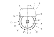
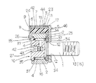
図1〜図6を参照して,この発明によるフォロア軸受の潤滑装置の一実施例を説明する。この発明によるフォロア軸受の潤滑装置について,フォロア軸受10は,カムフォロアやローラフォロアであって,この実施例では,概して,雄ねじ部1S等の取付け部13を備えたスタッドである支持軸1,及び支持軸1に針状ころ等のローラ4を介して相対回転自在に取り付けられた外輪2を備えている。このフォロア軸受の潤滑装置は,フォロア軸受10に対して,外輪2に潤滑剤を給脂する潤滑部材15を収容する収容室6を有するケーシング3がフォロア軸受10に外付けされているものである。フォロア軸受10は,一端にフランジ部35を備え且つ他端に取付け部材13の雄ねじ部1Sが形成された支持軸1,支持軸1に回転自在に嵌挿して取り付けられた外輪2,支持軸1と外輪2との間に介在された複数個の針状ころのローラ4,ローラ4を保持する保持器37,及び反フランジ部35側で保持器37に接して支持軸1に嵌挿されたリング状の側板34から構成されている。フォロア軸受10は,例えば,図5に示されているように,各種の装置に組み込まれている。フォロア軸受10は,その支持軸1が固定部材22に形成された取付け用孔41に挿通され,支持軸1に形成された雄ねじ部1Sにナット28を螺入締結して,固定部材22に固定されている。固定部材22は,取付け用孔41の回りにボス部36が形成されている。また,フォロア軸受10の外輪2は,相手部材であるトラック部材30のトラック面31に回転自在に設置されている。支持軸1の端部には,一端側に雄ねじ部1Sが設けられ,雄ねじ部1Sとは反対側の支持軸1の端部には,六角棒スパナを使って支持軸1を締め付け固定するための六角穴27が形成されている。六角穴27の奥側には,潤滑剤をフォロア軸受10のローラ4に給脂するためのグリースニップル43が配設されている。グリースニップル43の更に奥側には,フォロア軸受10のローラ4に給脂するための給脂通路42が形成されている。
Hereinafter, an embodiment of a lubricating device for a follower bearing according to the present invention will be described with reference to the drawings.
An embodiment of a lubricating device for a follower bearing according to the present invention will be described with reference to FIGS. In the lubricating device for a follower bearing according to the present invention, the follower bearing 10 is a cam follower or a roller follower, and in this embodiment, the
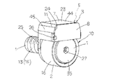
この発明によるフォロア軸受の潤滑装置は,概して,フォロア軸受10に外付けされたケーシング3,ケーシング3内に収容された潤滑部材15,及び潤滑部材15を外輪2に弾性的に接触させるばね部材17から構成されている。ケーシング3は,潤滑部材15の収容室6を備え且つ外輪2の外側の一部を覆うケース7,及びケース7に形成された開口部9を閉鎖するためケース7に開閉自在に取り付けられる蓋部材8から構成されており,ケース7の収容室6に潤滑部材15が出し入れ自在に設置されている。潤滑装置5を構成する潤滑部材15は,特に,潤滑装置5のケーシング3を構成するケース7にその開口部9を通じて収容室6に取付け取外し可能に配設されることを特徴としている。また,ケース7は,外輪2を覆って潤滑部材15を収容する収容室6が形成された本体部11,該本体部11の一端に一体構造に形成されて支持軸1を嵌挿する挿通孔12を備えたリング部25から構成されている。この実施例では,ケース7は,上部23,両側部45及びリング部25を備えた後部46から形成されている。ケース7の前部には,開口部9が形成されており,開口部9は,蓋部材8によって閉鎖される形式に構成されている。ケース7に形成された開口部9は,ケース7の軸方向に一方の端面24に形成されている。また,ケース7の上部23の中央部には,ばね部材17をケーシング3内に位置決めするため,軸方向に延びるV溝状の位置決め凹部32が形成されている。ケース7には,潤滑装置5を収容室6に配設した状態で,潤滑装置5が収容室6内に安定して設置されるように,ケース7の本体部11の内側対向面に軸方向に延びる一対の段部形状の掛け止め段部33が形成されている。また,ケーシング3を構成する蓋部材8は,ケース7の軸方向端面24に形成された開口部9を密封するため,ケース7の一端側に蝶番26によって回転自在に取り付けられ,他端側がケース7に設けた係止凸部18に係止される係合孔部19を備えている。
The lubricating device for a follower bearing according to the present invention generally includes a
この実施例では,潤滑装置5は,潤滑剤が含浸された潤滑部材15,潤滑部材15を配設するケーシング3,及び潤滑部材15に取り付けられた板ばね形状のばね部材17から構成されている。潤滑部材15は,幅方向に隔置して軸方向に双胴状に延びる一対の給油部14と,給油部14を一体構造に連係する連係部40から構成されている。潤滑部材15には,給油部14が形成された部位に対応して軸方向にそれぞれ延びる凹溝39が形成されている。また,潤滑部材15は,幅方向端部が凹溝39に沿って端面側に突出して延び,且つケース7の一対の掛け止め段部33に載置して潤滑部材15をケース7内に支持する掛け止め支持部38を備えている。また,ケース7に形成された位置決め凹部32には,稜線状の板ばねに形成されたばね部材17がその軸方向中央の稜線が係止し,それによって,潤滑部材15はケース7内に位置決めして配設されている。潤滑部材15の給油部14は,外輪2の外周面16に,ばね部材17によって弾性変形して当接させられ,外輪2の外周面16に接触して給油するように構成されている。言い換えれば,潤滑部材15は,外輪2の周方向に隔置して軸方向全域に沿って接する一対の給油部14を備えている。また,潤滑部材15は,潤滑剤が含浸された多孔質成形体で構成されている。潤滑剤を含浸した多孔質成形体は,例えば,高分子量の合成樹脂微粒子を押し固めた状態で加熱成形した焼結樹脂であって,合成樹脂微粒子間が連通した空間即ちオープンポアに形成され,該オープンポアは,潤滑剤が含浸されるように保形されている。
In this embodiment, the
また,フォロア軸受10は,相手部材であるトラック部材30のトラック面31の変位に追従して外輪2が回転自在になって運動するものである。フォロア軸受10を固定部材22に固定するには,フォロア軸受10の支持軸1をケース7のリング部25に形成された挿通孔12に通し,次いで,固定部材22に形成された取付け用孔41に支持軸1を通し,リング部25を取付け用孔41の周囲のボス部36に位置させる。そこで,支持軸1に座金29を通して座金29を固定部材22の面に当て,次いで支持軸1の雄ねじ部1Sにナット28を螺入して締結する。この状態で,ケース7は,固定部材22に対してフォロア軸受10と一緒に固定された状態になる。通常,潤滑装置5をケース7内に配設するのは,ケーシング3をフォロア軸受10にセットするのに先駆けて配設するが,ケーシング3をフォロア軸受10にセットした後でもよいものである。即ち,フォロア軸受10において,外輪2とケーシングと3が配設された支持軸1は,固定部材22に形成された取付け用孔41に挿通された状態で,支持軸1の取付け部13を構成する雄ねじ部1sにナット28が螺入締結されて,それによって,フォロア軸受10が固定部材22に固定されるものである。
Further, the follower bearing 10 is configured such that the
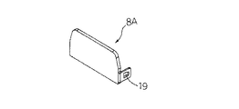
次に,図7及び図8を参照して,この発明によるフォロア軸受の潤滑装置の別の実施例を説明する。図7及び図8において,図1〜図6に示すフォロア軸受の潤滑装置の各種の部材と同一の機能を有する部材には同一符号を付してそれらの説明は省略する。この発明によるフォロア軸受の潤滑装置は,ケーシング3を構成するケース7Aと蓋部材8Aとが別々に分離される構造に形成されている。蓋部材8Aは,ケース7Aに形成された開口部9を開閉するためケース7Aの両端に設けられた係止凸部18に係止される係合孔部19を両端部にそれぞれ備えている。ケース7Aは,上部23,両側部45及びリング部25を備えた後部46から形成されている。ケース7Aの前部は,開口部9に形成されており,開口部9は,蓋部材8Aによって閉鎖される形式に構成されている。潤滑装置5をケース7Aの収容室6に配置するには,蓋部材8Aをケース7Aから取り外し,開口部9を開いて潤滑装置5を収容室6に挿通して配設する。
Next, with reference to FIGS. 7 and 8, another embodiment of a lubricating device for a follower bearing according to the present invention will be described. 7 and 8, members having the same functions as those of the various members of the lubricating device for the follower bearing shown in FIGS. 1 to 6 are denoted by the same reference numerals, and description thereof will be omitted. The lubricating device for a follower bearing according to the present invention is formed in a structure in which the case 7A and the
また,図9を参照して,この発明によるフォロア軸受の潤滑装置の更に別の実施例を説明する。図9において,図1〜図6に示すフォロア軸受の潤滑装置の各種の部材と同一の機能を有する部材には同一符号を付してそれらの説明は省略する。この発明によるフォロア軸受の潤滑装置は,ケース7Bに形成された開口部9は,ケース7Bの上面に形成されている。ケース7Bの開口部9には,蓋部材8Bに閉鎖されるように形成されている。蓋部材8Bは,一端がケース7Bの側部に蝶番26で回転自在に取り付けられており,他端には係合孔部21を備えている。ケース7Bの側部には,蓋部材8Bの係合孔部21が係合する係止凸部20を備えている。潤滑装置5は,ケース7Bの収容室6には上部に設けた蓋部材8Bを開けて上方から配設することができる。勿論,ケース7Bにも,掛け止めガイド部を備えており,潤滑装置5は,ケース7Bの掛け止めガイド部に載置されてケース7Bの収容室6に配設される。
Still another embodiment of the lubricating device for follower bearing according to the present invention will be described with reference to FIG. In FIG. 9, members having the same functions as the various members of the lubricating device for the follower bearing shown in FIGS. 1 to 6 are denoted by the same reference numerals, and the description thereof will be omitted. In the lubricating device for a follower bearing according to the present invention, the
また,図10及び図11を参照して,この発明によるフォロア軸受の潤滑装置の他の実施例を説明する。図10及び図11において,図1〜図6に示すフォロア軸受の潤滑装置の各種の部材と同一の機能を有する部材には同一符号を付してそれらの説明は省略する。この発明によるフォロア軸受の潤滑装置は,ケース7Cと蓋部材8Cとは,弾性変形可能な薄肉部材から成る一種の蝶番26Cによって3者が一体構造になって形成されている。蓋部材8Cは係合孔部19を備えており,蓋部材8Cの係合孔部19は,ケース7Cに設けた係止凸部18に係合してケース7Cの前部に形成されている開口部9が閉鎖されるように構成されている。言い換えれば,ケースCと蓋部材8Cと蝶番26Cとは,一体構造に成形されている。
Another embodiment of the lubricating device for a follower bearing according to the present invention will be described with reference to FIGS. 10 and 11, members having the same functions as those of the various members of the lubricating device for the follower bearing shown in FIGS. 1 to 6 are denoted by the same reference numerals, and description thereof will be omitted. In the lubricating device for a follower bearing according to the present invention, the
この発明によるフォロア軸受の潤滑装置は,例えば,工作機械,産業用ロボット,電子部品装置,OA機器等の各種の装置に組み込んで使用されるものである。 The lubricating device for a follower bearing according to the present invention is used by being incorporated in various devices such as a machine tool, an industrial robot, an electronic component device, and an OA device.
1 支持軸
1S 雄ねじ
2 外輪
3 ケーシング
4 ローラ
5 潤滑装置
6 収容室
7,7A,7B,7C ケース
8,8A,8B,8C 蓋部材
9 開口部
10 フォロア軸受
11 本体部
12 挿通孔
13 取付け部
14 給油部
15 潤滑部材
16 外周面
17 ばね部材
18,20 係止凸部
19,21 係合孔部
23 上部
24 端面
25 リング部
26 蝶番
28 ナット
30 トラック部材
31 トラック面
32 位置決め凹部
33 掛け止め段部
38 掛け止め支持部
41 取付け用孔
DESCRIPTION OF
Claims (10)
前記ケーシングは,前記収容室を備えて前記外輪の外側の一部を覆うケース,及び前記ケースに形成された前記収容室の開口部を閉鎖するため前記ケースに開閉自在に取り付けられる蓋部材から構成されており,
前記ケースは,前記外輪を覆って前記潤滑部材を収容する前記収容室が形成された本体部,及び前記本体部の一端に一体構造に形成され且つ前記支持軸を嵌挿する挿通孔が形成されたリング部から構成されており,
前記ケーシングの前記ケースを前記フォロア軸受から取り外すことなく,前記ケーシングの前記蓋部材を開けて前記ケースの前記開口部を通じて前記潤滑部材を前記収容室に取付け取外し可能に配設されることを特徴とするフォロア軸受の潤滑装置。 For a support shaft having an attachment portion and a follower bearing having an outer ring relatively rotatably attached to the support shaft via a roller, a housing chamber for housing a lubricating member for supplying lubricant to the outer ring is provided. A follower bearing lubrication device, comprising a casing provided externally to the follower bearing;
The casing includes a case provided with the storage chamber and covering a part of the outside of the outer ring, and a lid member openably and closably attached to the case to close an opening of the storage chamber formed in the case. Has been
The case has a main body in which the housing chamber for forming the lubricating member is formed so as to cover the outer race, and an insertion hole formed integrally with one end of the main body to fit the support shaft. Ring part,
Without removing the casing of the casing from the follower bearing, and characterized in that it is mounted removably disposed in the housing chamber the lubricating member through the opening of the case is opened the lid member of the casing Follower bearing lubrication device.
Priority Applications (1)
| Application Number | Priority Date | Filing Date | Title |
|---|---|---|---|
| JP2015187109A JP6639847B2 (en) | 2015-09-24 | 2015-09-24 | Follower bearing lubrication system |
Applications Claiming Priority (1)
| Application Number | Priority Date | Filing Date | Title |
|---|---|---|---|
| JP2015187109A JP6639847B2 (en) | 2015-09-24 | 2015-09-24 | Follower bearing lubrication system |
Publications (3)
| Publication Number | Publication Date |
|---|---|
| JP2017061977A JP2017061977A (en) | 2017-03-30 |
| JP2017061977A5 JP2017061977A5 (en) | 2018-10-11 |
| JP6639847B2 true JP6639847B2 (en) | 2020-02-05 |
Family
ID=58429355
Family Applications (1)
| Application Number | Title | Priority Date | Filing Date |
|---|---|---|---|
| JP2015187109A Active JP6639847B2 (en) | 2015-09-24 | 2015-09-24 | Follower bearing lubrication system |
Country Status (1)
| Country | Link |
|---|---|
| JP (1) | JP6639847B2 (en) |
Families Citing this family (2)
| Publication number | Priority date | Publication date | Assignee | Title |
|---|---|---|---|---|
| CN111512086B (en) * | 2018-01-31 | 2022-08-09 | 株式会社三共制作所 | Lubricating device and cam mechanism provided with same |
| JP2024000656A (en) * | 2022-06-21 | 2024-01-09 | 日本トムソン株式会社 | Follower bearing having cover |
Family Cites Families (5)
| Publication number | Priority date | Publication date | Assignee | Title |
|---|---|---|---|---|
| JP4050638B2 (en) * | 2003-03-11 | 2008-02-20 | 日本トムソン株式会社 | Follower bearing with lubrication device |
| JP4278659B2 (en) * | 2006-04-26 | 2009-06-17 | 日本トムソン株式会社 | Bearing lubrication equipment |
| JP5076752B2 (en) * | 2006-10-06 | 2012-11-21 | 日本精工株式会社 | Linear motion guidance device |
| JP5275183B2 (en) * | 2009-09-14 | 2013-08-28 | 日本トムソン株式会社 | Follower bearing lubrication system |
| JP2012146944A (en) * | 2010-12-21 | 2012-08-02 | Juki Corp | Component mounting device |
-
2015
- 2015-09-24 JP JP2015187109A patent/JP6639847B2/en active Active
Also Published As
| Publication number | Publication date |
|---|---|
| JP2017061977A (en) | 2017-03-30 |
Similar Documents
| Publication | Publication Date | Title |
|---|---|---|
| JP6639847B2 (en) | Follower bearing lubrication system | |
| US8113714B2 (en) | Linear motion guide unit | |
| CN111433469A (en) | Sliding bearing | |
| JP2014231856A (en) | Rolling bearing | |
| JP5756302B2 (en) | Minimal linear motion guide unit with lubrication function | |
| US20080247693A1 (en) | Snap-In Bearing Insert | |
| JP6393496B2 (en) | Linear motion guide unit with lubrication member | |
| KR102354290B1 (en) | Cassette seal | |
| JP4278659B2 (en) | Bearing lubrication equipment | |
| JP2017190866A (en) | Rolling bearing unit | |
| JP3922770B2 (en) | One-way clutch | |
| JP2008232284A (en) | Hermetically-sealed device of rolling bearing | |
| JP6228503B2 (en) | Ball screw nut | |
| US20110061974A1 (en) | Lubricating Apparatus For Follower Bearing | |
| JP4838176B2 (en) | Slide bearing | |
| WO2017179617A1 (en) | Rolling bearing unit | |
| KR100288609B1 (en) | One-Way Clutch | |
| KR200380539Y1 (en) | a door-hinge inserted a radial bearing | |
| EP3105477A1 (en) | Axially sliding seal | |
| JP2021095967A (en) | Holder and rolling bearing | |
| CN110273941B (en) | Friction clamping device | |
| TW201734332A (en) | Ball screw capable of achieving a maintenance-free lubrication by supplying a lubricant to an oil supply member from an oil-containing member | |
| JP2000103335A (en) | Bearing device for railway vehicle | |
| JP5401848B2 (en) | Railway vehicle bearing device | |
| JP2010116107A (en) | Axle device for railway vehicle |
Legal Events
| Date | Code | Title | Description |
|---|---|---|---|
| A521 | Request for written amendment filed |
Free format text: JAPANESE INTERMEDIATE CODE: A523 Effective date: 20180831 |
|
| A621 | Written request for application examination |
Free format text: JAPANESE INTERMEDIATE CODE: A621 Effective date: 20180831 |
|
| A977 | Report on retrieval |
Free format text: JAPANESE INTERMEDIATE CODE: A971007 Effective date: 20190719 |
|
| A131 | Notification of reasons for refusal |
Free format text: JAPANESE INTERMEDIATE CODE: A131 Effective date: 20190820 |
|
| A521 | Request for written amendment filed |
Free format text: JAPANESE INTERMEDIATE CODE: A523 Effective date: 20190909 |
|
| TRDD | Decision of grant or rejection written | ||
| A01 | Written decision to grant a patent or to grant a registration (utility model) |
Free format text: JAPANESE INTERMEDIATE CODE: A01 Effective date: 20191217 |
|
| A61 | First payment of annual fees (during grant procedure) |
Free format text: JAPANESE INTERMEDIATE CODE: A61 Effective date: 20191225 |
|
| R150 | Certificate of patent or registration of utility model |
Ref document number: 6639847 Country of ref document: JP Free format text: JAPANESE INTERMEDIATE CODE: R150 |
|
| R250 | Receipt of annual fees |
Free format text: JAPANESE INTERMEDIATE CODE: R250 |