JP2017190866A - Rolling bearing unit - Google Patents

Rolling bearing unit Download PDF

Info

Publication number
JP2017190866A
JP2017190866A JP2017071693A JP2017071693A JP2017190866A JP 2017190866 A JP2017190866 A JP 2017190866A JP 2017071693 A JP2017071693 A JP 2017071693A JP 2017071693 A JP2017071693 A JP 2017071693A JP 2017190866 A JP2017190866 A JP 2017190866A
Authority
JP
Japan
Prior art keywords
connecting piece
rolling bearing
circumferential direction
outer ring
seal member
Prior art date
Legal status (The legal status is an assumption and is not a legal conclusion. Google has not performed a legal analysis and makes no representation as to the accuracy of the status listed.)
Pending
Application number
JP2017071693A
Other languages
Japanese (ja)
Inventor
翔太 東穂
Shota TOHO
翔太 東穂
直太 山本
Naota Yamamoto
直太 山本
宙史 内村
Hiroshi Uchimura
宙史 内村
Current Assignee (The listed assignees may be inaccurate. Google has not performed a legal analysis and makes no representation or warranty as to the accuracy of the list.)
NTN Corp
Original Assignee
NTN Corp
NTN Toyo Bearing Co Ltd
Priority date (The priority date is an assumption and is not a legal conclusion. Google has not performed a legal analysis and makes no representation as to the accuracy of the date listed.)
Filing date
Publication date
Application filed by NTN Corp, NTN Toyo Bearing Co Ltd filed Critical NTN Corp
Priority to PCT/JP2017/014969 priority Critical patent/WO2017179617A1/en
Publication of JP2017190866A publication Critical patent/JP2017190866A/en
Pending legal-status Critical Current

Links

Images

Landscapes

  • Sealing Of Bearings (AREA)
  • Rolling Contact Bearings (AREA)
  • Sealing Using Fluids, Sealing Without Contact, And Removal Of Oil (AREA)
  • Mounting Of Bearings Or Others (AREA)

Abstract

PROBLEM TO BE SOLVED: To enable a seal member to be firmly fixed to an outer ring, the seal member configured to close a lateral opening of a bearing space of a rolling bearing.SOLUTION: A rolling bearing unit includes: an outer ring 1 fixed into a housing 11; an inner ring 2 opposite to the outer ring 1; a toric seal member 40 covering a lateral opening D of a bearing space between the outer ring 1 and the inner ring 2; an oil passage 12 for lubricant arranged along an axial direction between an inner diameter surface of the housing 11 and an outer diameter surface of the outer ring 1; and a connection piece 80 inserted into the oil passage 12 and fixing the seal member 40 to the outer ring 1. The seal member 40 comprises a toric connection body formed by connecting a plurality of split seal members 40' split along a circumferential direction with the connection pieces 80. The connection piece 80 and the split seal member 40' include folding prevention means of regulating bending of connection parts between the split seal members 40' adjacent in the circumferential direction.SELECTED DRAWING: Figure 1

Description

この発明は、オイル潤滑される転がり軸受に関し、特に、潤滑用のオイルに含まれる異物を捕捉する機能を備えた転がり軸受ユニットに関するものである。   The present invention relates to an oil-lubricated rolling bearing, and more particularly to a rolling bearing unit having a function of capturing foreign matter contained in lubricating oil.

輸送機器や産業機械、その他各種機器の可動部には、転がり軸受が組み込まれている。このような機器の中には、油潤滑される転がり軸受以外に潤滑が必要な作動機構部を有し、その作動機構部と転がり軸受とが、共通のオイルで潤滑される構造となっているものがある。作動機構部としては、例えば、ギヤ同士の噛み合い部分や部材同士の摺接部分等が挙げられる。   Rolling bearings are incorporated in movable parts of transportation equipment, industrial machinery, and other various equipment. In such a device, there is an operation mechanism portion that requires lubrication in addition to the oil-lubricated rolling bearing, and the operation mechanism portion and the rolling bearing have a structure that is lubricated with a common oil. There is something. As an operation mechanism part, the meshing part of gears, the sliding contact part of members, etc. are mentioned, for example.

例えば、オイルポンプ等は、機器の内部に転がり軸受と作動機構部とを有している。また、特に、オイルポンプは、その転がり軸受と作動機構部とを備えた機器の外部にある他の作動機構部に向かって、内部の潤滑油を送り出す機能を備えている。   For example, an oil pump or the like has a rolling bearing and an operating mechanism part inside the device. In particular, the oil pump has a function of feeding the internal lubricating oil toward another operating mechanism portion outside the device including the rolling bearing and the operating mechanism portion.

ところで、転がり軸受の軸受空間からは、摩耗粉(鉄粉等)等の異物が発生することがある。この異物が、潤滑油の循環経路の途中にある作動機構部に侵入すると、異物の噛み込みによって、機器の耐久性を低下させる場合がある。また、場合によっては、機器の動作不良・故障・破損に繋がることもある。   Incidentally, foreign matter such as wear powder (iron powder or the like) may be generated from the bearing space of the rolling bearing. If the foreign matter enters the operating mechanism part in the middle of the lubricating oil circulation path, the durability of the device may be reduced due to the biting of the foreign matter. In some cases, it may lead to malfunction / failure / damage of the equipment.

そこで、例えば、特許文献1には、鉄粉等からなる異物が循環経路内に流通する潤滑油に混入した場合に、その異物をセンサが備える磁石に吸着させ、吸着した異物が堆積していくことにより金属製のケーシングと磁石とが電気的に導通した場合に、警報を発信する潤滑油の鉄粉汚濁検知方法が開示されている(例えば、特許文献1参照)。   Therefore, for example, in Patent Document 1, when a foreign matter made of iron powder or the like is mixed in the lubricating oil flowing in the circulation path, the foreign matter is attracted to a magnet provided in the sensor, and the attracted foreign matter is accumulated. Thus, there is disclosed a method for detecting iron powder contamination of lubricating oil that issues an alarm when a metal casing and a magnet are electrically connected (see, for example, Patent Document 1).

また、特許文献2には、転がり軸受の内外輪間に位置する軸受空間の端部を閉じるシールリングに、異物を捕捉するフィルタを設けた技術が開示されている。   Patent Document 2 discloses a technique in which a filter for capturing foreign matter is provided on a seal ring that closes an end of a bearing space located between inner and outer rings of a rolling bearing.

特開平7−280180号公報JP 7-280180 A 特開2012−102767号公報JP 2012-102767 A

上記のように、転がり軸受から発生する摩耗粉(鉄粉等)等の異物が、潤滑油の循環経路の途中にある作動機構部に侵入することは好ましくない。特に、オイルポンプ用の転がり軸受ユニットにおいて、軸受から発生する大きな剥離片は、そのオイルポンプ自身の作動機構部や、そのオイルポンプによって送り出される潤滑油の循環経路内にある他の作動機構部の部品に対して、動作不良・故障・破損の原因となる。このため、特許文献2に示すような、フィルタ付きの円環状のシール部材を設置することで、転がり軸受内から作動機構部への異物の流出防止が必要となる。   As described above, it is not preferable for foreign matter such as wear powder (iron powder or the like) generated from the rolling bearing to enter the operating mechanism portion in the middle of the lubricating oil circulation path. In particular, in a rolling bearing unit for an oil pump, a large peeling piece generated from the bearing is caused by an operating mechanism portion of the oil pump itself or other operating mechanism portions in a circulation path of lubricating oil sent out by the oil pump. It may cause malfunction, failure or damage to the parts. For this reason, by installing an annular seal member with a filter as shown in Patent Document 2, it is necessary to prevent foreign matter from flowing out of the rolling bearing into the operating mechanism.

ところで、シール部材を外輪側に固定した場合、そのシール部材は外輪にしっかりと固定されている必要がある。シール部材が外輪にしっかりと固定されていないと、シール部材と外輪との間に隙間を生じ、軸受空間内から軸受空間外へ異物が流出してしまう事態にもつながる。   By the way, when the seal member is fixed to the outer ring side, the seal member needs to be firmly fixed to the outer ring. If the seal member is not firmly fixed to the outer ring, a gap is formed between the seal member and the outer ring, leading to a situation where foreign matter flows out of the bearing space to the outside of the bearing space.

そこで、この発明の課題は、転がり軸受の軸受空間の側方開口を閉じるシール部材を、外輪に対してしっかりと固定できるようにすることである。   Then, the subject of this invention is enabling it to fix firmly the sealing member which closes the side opening of the bearing space of a rolling bearing with respect to an outer ring | wheel.

上記の課題を解決するために、この発明は、ハウジング内に固定される外輪と、前記外輪に対向する内輪と、前記外輪と前記内輪との間の軸受空間に配置される転動体と、前記外輪の軸方向一端側に取り付けられて前記軸受空間の側方開口を覆う円環状のシール部材と、前記ハウジングの内径面と前記外輪の外径面との間に軸方向に沿って配置される潤滑油用の油路と、前記油路内に入り込み前記シール部材を前記外輪に固定する連結片と、を備え、前記シール部材は周方向に沿って分割された複数の分割シール部材が前記連結片によって接続されて円環状の連結体とされ、前記連結片と前記分割シール部材は、周方向に隣り合う前記分割シール部材同士の接続部の屈曲を規制する折れ防止手段を備える転がり軸受ユニットを採用した。   In order to solve the above problems, the present invention provides an outer ring fixed in a housing, an inner ring facing the outer ring, a rolling element disposed in a bearing space between the outer ring and the inner ring, An annular seal member that is attached to one end of the outer ring in the axial direction and covers a side opening of the bearing space, and is disposed along the axial direction between the inner diameter surface of the housing and the outer diameter surface of the outer ring. An oil passage for lubricating oil; and a connecting piece that enters the oil passage and fixes the seal member to the outer ring. The seal member includes a plurality of divided seal members that are divided along a circumferential direction. A rolling bearing unit is provided that is connected by a piece to form an annular coupling body, and the coupling piece and the divided seal member are provided with a bending preventing means for restricting bending of a connection portion between the divided seal members adjacent in the circumferential direction. Adopted.

前記連結片及び前記分割シール部材の一方に設けた係止凸部が他方に設けた係止孔に入り込むことで、前記連結片は周方向に隣り合う前記分割シール部材の端部同士が周方向へスライド自在に接続されている構成を採用することができる。   The engaging protrusion provided on one of the connecting piece and the split seal member enters the engaging hole provided on the other, so that the end portions of the split seal members adjacent to each other in the circumferential direction are in the circumferential direction. It is possible to adopt a configuration that is slidably connected to each other.

ここで、前記係止凸部は前記連結片に、前記係止孔は前記分割シール部材に設けられる構成を採用することができる。   Here, it is possible to adopt a configuration in which the locking projection is provided in the connecting piece and the locking hole is provided in the divided seal member.

前記連結片は、周方向に隣り合う前記分割シール部材の端部に当接する基部と、前記基部から周方向両側へ伸びる対の支え部とを備え、前記係止凸部は、前記支え部に設けられる構成を採用することができる。   The connecting piece includes a base portion that abuts against an end portion of the divided seal member adjacent in the circumferential direction, and a pair of support portions extending from the base portion to both sides in the circumferential direction, and the locking convex portion is provided on the support portion. The provided structure can be adopted.

これらの各態様において、前記折れ防止手段は、周方向に隣り合う前記分割シール部材のうち少なくとも一方の前記分割シール部材と前記連結片との間で、複数の前記係止凸部が前記係止孔に入り込んで接続されて構成される構成を採用することができる。   In each of these aspects, the break prevention means includes a plurality of the locking projections between the at least one of the divided seal members adjacent to each other in the circumferential direction and the connecting piece. It is possible to adopt a configuration in which the holes are connected and connected.

また、これらの各態様において、前記折れ防止手段は、周方向に隣り合う前記分割シール部材のうち少なくとも一方の前記分割シール部材と前記連結片との間で、非円形の前記係止凸部が同形状の前記係止孔に入り込んで接続されて構成される構成を採用することができる。   Further, in each of these aspects, the break prevention means includes a non-circular locking projection between at least one of the divided seal members adjacent to the circumferential direction and the connecting piece. It is possible to adopt a configuration that is configured to enter and be connected to the locking hole having the same shape.

この発明は、周方向に沿って分割された複数の分割シール部材を連結片によって接続して円環状の連結体からなるシール部材とする場合に、連結片と分割シール部材が、周方向に隣り合う分割シール部材同士の接続部の屈曲を規制する折れ防止手段を備える構成としたので、転がり軸受の軸受空間の側方開口を閉じるシール部材を、外輪に対してしっかりと固定できるようになる。   In the present invention, when a plurality of divided seal members divided along the circumferential direction are connected by a coupling piece to form a sealing member made of an annular coupling body, the coupling piece and the divided sealing member are adjacent to each other in the circumferential direction. Since the structure is provided with a break prevention means for restricting the bending of the connecting portion between the matching divided seal members, the seal member that closes the side opening of the bearing space of the rolling bearing can be firmly fixed to the outer ring.

この発明の第一の実施形態を示し、(a)は転がり軸受を複数備えた軸受ユニットの側面図、(b)は縦断面図1 shows a first embodiment of the present invention, in which (a) is a side view of a bearing unit including a plurality of rolling bearings, and (b) is a longitudinal sectional view. (a)はシール部材を備えた転がり軸受の要部平面図、(b)はその斜視図(A) is a principal part top view of the rolling bearing provided with the sealing member, (b) is the perspective view. (a)はシール部材を備えた転がり軸受の側面図、(b)は正面図(A) is a side view of a rolling bearing provided with a seal member, and (b) is a front view. シール部材の分解斜視図Exploded perspective view of seal member 分割シール部材同士を接続する連結片を示し、(a)は平面図、(b)は(a)の正面図、(c)は(a)の右側面図The coupling piece which connects division | segmentation sealing members is shown, (a) is a top view, (b) is a front view of (a), (c) is a right view of (a). 分割シール部材同士の接続部を示す(a)(b)は要部拡大図、(c)は断面図(A) (b) which shows the connection part of division | segmentation sealing members is an enlarged view of the principal part, (c) is sectional drawing. 連結片の変形例を示し、(a)(b)は径を大きくした状態を示す平面図及び断面図、(c)(d)は径を小さくした状態を示す平面図及び断面図The modification of a connection piece is shown, (a) (b) is the top view and sectional drawing which show the state which enlarged the diameter, (c) (d) is the top view and sectional drawing which shows the state which reduced the diameter (a)(b)はそれぞれ変形例を示す平面図、(c)(d)はさらなる変形例を示す平面図及び断面図(A) (b) is a top view which shows a modification, respectively, (c) (d) is a top view and sectional drawing which show the further modification. (a)は連結片付近の詳細を示す断面図、(b)はシール部材の要部拡大斜視図、(c)は(b)の要部断面図(A) is sectional drawing which shows the detail of a connection piece vicinity, (b) is a principal part expanded perspective view of a sealing member, (c) is principal part sectional drawing of (b). シールリングに作用する荷重とそれに対する部材の変形を示す説明図Explanatory drawing which shows the load which acts on a seal ring, and the deformation | transformation of the member with respect to it 連結片の変形例を示す分解斜視図Exploded perspective view showing a modification of the connecting piece (a)(b)はそれぞれ連結片付近の詳細を示す断面図、(c)は(b)の拡大図、(d)は連結片のさらなる変形例を示す斜視図(A) (b) is sectional drawing which shows the detail of each connection piece vicinity, (c) is an enlarged view of (b), (d) is a perspective view which shows the further modification of a connection piece. この発明の第二の実施形態を示し、(a)は転がり軸受を複数備えた軸受ユニットの側面図、(b)は縦断面図The second embodiment of the present invention is shown, (a) is a side view of a bearing unit provided with a plurality of rolling bearings, (b) is a longitudinal sectional view. (a)はシール部材を備えた転がり軸受の要部平面図、(b)はその斜視図(A) is a principal part top view of the rolling bearing provided with the sealing member, (b) is the perspective view. (a)はシール部材を備えた転がり軸受の側面図、(b)は正面図(A) is a side view of a rolling bearing provided with a seal member, and (b) is a front view. 分割シール部材同士を接続する連結片を示し、(a)は平面図、(b)は(a)の正面図、(c)は(a)の右側面図The coupling piece which connects division | segmentation sealing members is shown, (a) is a top view, (b) is a front view of (a), (c) is a right view of (a). (a)(b)は分割シール部材同士の接続部を示す要部拡大図(A) (b) is a principal part enlarged view which shows the connection part of division | segmentation seal members. 連結片の変形例を示す分解斜視図Exploded perspective view showing a modification of the connecting piece (a)(b)はそれぞれ連結片付近の詳細を示す断面図、(c)は(b)の拡大図、(d)は連結片のさらなる変形例を示す斜視図(A) (b) is sectional drawing which shows the detail of each connection piece vicinity, (c) is an enlarged view of (b), (d) is a perspective view which shows the further modification of a connection piece. (a)(b)は連結片の比較例を示す断面図(A) (b) is sectional drawing which shows the comparative example of a connection piece

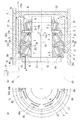
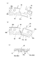
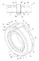
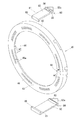
この発明の実施形態を、図面に基づいて説明する。図1〜図12に、この発明の第一の実施形態を示す。この実施形態は、シール部材40を取り付けた軸受ユニット20を備えたオイルポンプ装置10である。   Embodiments of the present invention will be described with reference to the drawings. 1 to 12 show a first embodiment of the present invention. This embodiment is an oil pump device 10 including a bearing unit 20 to which a seal member 40 is attached.

オイルポンプ装置10は、機器の内部に転がり軸受を複数備えた軸受ユニット20と、オイルポンプ60の作動機構部30とを有している。   The oil pump device 10 includes a bearing unit 20 having a plurality of rolling bearings inside the device, and an operating mechanism 30 of the oil pump 60.

軸受ユニット20は、ハウジング11の内部に、油潤滑される3つの転がり軸受21,22,23を並列して備えている。これらの転がり軸受21,22,23によって、オイルポンプ60の作動機構部30に通じる軸部材32を、固定のハウジング11に対して軸周り回転自在に支持している。   The bearing unit 20 includes three rolling bearings 21, 22, and 23 that are oil-lubricated in parallel inside the housing 11. By these rolling bearings 21, 22, and 23, the shaft member 32 that communicates with the operating mechanism portion 30 of the oil pump 60 is supported by the fixed housing 11 so as to be rotatable about the axis.

各転がり軸受21,22,23は、外側軌道輪1と内側軌道輪2の各軌道面1a,2aの間に、転動体3が組み込まれている。転動体3は、保持器4によって周方向に保持されている。以下、外側軌道輪1を外輪1と、内側軌道輪2を内輪2と称する。   In each of the rolling bearings 21, 22, and 23, a rolling element 3 is incorporated between the raceway surfaces 1 a and 2 a of the outer raceway ring 1 and the inner raceway ring 2. The rolling element 3 is held in the circumferential direction by a cage 4. Hereinafter, the outer race 1 is referred to as an outer race 1 and the inner race 2 is referred to as an inner race 2.

外輪1はハウジング11の内径面に圧入されて、そのハウジング11に対して相対回転不能に固定されている。内輪2は、軸部材32の外周に圧入されて、その軸部材32に対して相対回転不能に固定されている。   The outer ring 1 is press-fitted into the inner diameter surface of the housing 11 and fixed to the housing 11 so as not to rotate relative to the housing 11. The inner ring 2 is press-fitted into the outer periphery of the shaft member 32 and is fixed to the shaft member 32 so as not to rotate relative to the shaft member 32.

この実施形態では、転がり軸受21,22,23として、転動体3として円すいころを用いた円すいころ軸受を採用しているが、円すいころ軸受以外の転がり軸受を採用してもよく、また、その転がり軸受21,22,23の並列数は、装置の仕様に応じて自由に設定できる。   In this embodiment, as the rolling bearings 21, 22, and 23, tapered roller bearings using tapered rollers are employed as the rolling elements 3, but rolling bearings other than tapered roller bearings may be employed. The parallel number of the rolling bearings 21, 22, and 23 can be freely set according to the specifications of the apparatus.

オイルポンプ60の作動機構部30は、ポンプケーシング内に互いに相対回転することにより潤滑油を循環経路へ送り出すポンプ用ロータ(図示せず)を備える。ポンプ用ロータは、軸部材32の端部に設けた接続部材31に接続され、これにより、軸部材32の軸周りに回転可能な状態である。ロータへの駆動力は、図示しない駆動源から別途のルートで入力される。   The operating mechanism 30 of the oil pump 60 includes a pump rotor (not shown) that sends lubricating oil to the circulation path by rotating relative to each other in the pump casing. The pump rotor is connected to the connection member 31 provided at the end of the shaft member 32, and is thus rotatable around the shaft of the shaft member 32. The driving force to the rotor is input by a separate route from a driving source (not shown).

図1に示すように、並列する転がり軸受21,22,23のうち軸方向一方側、すなわち、作動機構部30寄りの2つの転がり軸受21,22は、円すいころの小径側端面同士が軸方向に沿って同じ側、すなわち、作動機構部30の反対側になるように配置されている。   As shown in FIG. 1, two rolling bearings 21, 22 near one side of the rolling mechanism 21, 22, 23 in parallel, that is, closer to the operating mechanism portion 30, have smaller diameter side end surfaces of the tapered rollers in the axial direction. Are arranged so as to be on the same side, that is, on the opposite side of the operating mechanism portion 30.

また、並列する転がり軸受21,22,23のうち軸方向他方側、すなわち、作動機構部30から最も遠い転がり軸受23は、円すいころの小径側端面が作動機構部30側になるように配置されている。すなわち、転がり軸受21,22と転がり軸受23とは、円すいころの小径側端面同士が背面合わせになるように配置されている。このため、内側軌道輪2の軌道面2aと外側軌道輪1の軌道面1aとは、3列の転がり軸受21,22,23のうち一方側の二つは、軸方向一方側から他方側へ向かって互いの距離が狭まるように設けられ、他方側の一つは、軸方向一方側から他方側へ向かって互いの距離が拡がるように設けられている。   The rolling bearings 23, 22, 23 arranged in parallel to each other in the axial direction, that is, the rolling bearing 23 farthest from the operating mechanism portion 30 is arranged so that the end surface on the small diameter side of the tapered roller is on the operating mechanism portion 30 side. ing. That is, the rolling bearings 21 and 22 and the rolling bearing 23 are disposed so that the small diameter side end surfaces of the tapered rollers are back to back. For this reason, the raceway surface 2a of the inner raceway ring 2 and the raceway surface 1a of the outer raceway ring 1 are two on one side of the three rows of rolling bearings 21, 22, 23 from the one side in the axial direction to the other side. The other side is provided so that the mutual distance increases from one side in the axial direction to the other side.

図1に示すように、軸方向に隣り合う転がり軸受21,22,23同士の間には、間座5,6,7が配置されている。   As shown in FIG. 1, spacers 5, 6, 7 are arranged between the rolling bearings 21, 22, 23 adjacent in the axial direction.

並列する転がり軸受21,22,23のうち軸方向一方側の2つの転がり軸受21,22の間には、内径側に、両側の内輪2,2の端面に当接する間座5が、外径側に、両側の外輪1,1の端面に当接する間座6が配置されている。   Between the two rolling bearings 21, 22 on the one side in the axial direction of the rolling bearings 21, 22, 23 that are arranged in parallel, a spacer 5 that is in contact with the end faces of the inner rings 2, 2 on both sides is provided on the inner diameter side. On the side, a spacer 6 is disposed that contacts the end faces of the outer rings 1 and 1 on both sides.

また、並列する転がり軸受21,22,23のうち軸方向他方側の2つの転がり軸受22,23の間には、内径側に、両側の内輪2,2の端面に当接する間座が、外径側に、両側の外輪1,1の端面に当接する間座7が配置されている。図1では、転がり軸受22,23の間における内径側の間座は図示していないが、転がり軸受22,23の周方向に沿って、潤滑油の循環経路13bの外径側の開口部以外の部分に、間座が配置されている。   In addition, between the two rolling bearings 22, 23 on the other axial side of the rolling bearings 21, 22, 23 arranged in parallel, a spacer that contacts the end surfaces of the inner rings 2, 2 on both sides is provided on the inner diameter side. A spacer 7 is disposed on the radial side so as to contact the end surfaces of the outer rings 1 and 1 on both sides. In FIG. 1, the inner diameter side spacer between the rolling bearings 22 and 23 is not shown, but along the circumferential direction of the rolling bearings 22 and 23, other than the opening on the outer diameter side of the lubricating oil circulation path 13 b. A spacer is arranged in the portion.

並列する転がり軸受21,22,23の両端は、軸方向一方側では、軸部材32の端部に設けたフランジ状の接続部材31の端面によって、また、軸方向他方側では、押え部材8の端面によって、軸部材32に対して軸方向へ動かないように固定されている。これらの接続部材31と押え部材8との固定によって、各転がり軸受には予圧が付与されている。   Both ends of the rolling bearings 21, 22, and 23 that are arranged in parallel are on the one side in the axial direction by the end face of the flange-shaped connection member 31 provided at the end of the shaft member 32, and on the other side in the axial direction, The end face is fixed so as not to move in the axial direction with respect to the shaft member 32. By preliminarily fixing the connecting member 31 and the pressing member 8, a preload is applied to each rolling bearing.

転がり軸受21,22,23によってハウジング11に支持された軸部材32は、オイルを送り出すためのポンプ本体に相当するオイルポンプ60内の回転部材である作動機構部30に接続されている。オイルポンプ60は、その駆動によって、外部にある他の作動機構部70に向かって、内部の潤滑油を送り出す機能を備えている。送り出した潤滑油は、潤滑油の経路に沿って流れて各部の作動機構部70を潤滑した後、やがてオイルポンプ60に戻ってくる。   The shaft member 32 supported by the housing 11 by the rolling bearings 21, 22, and 23 is connected to an operating mechanism unit 30 that is a rotating member in the oil pump 60 corresponding to a pump body for sending out oil. The oil pump 60 has a function of sending the internal lubricating oil toward the other operating mechanism portion 70 located outside by driving. The delivered lubricating oil flows along the lubricating oil path to lubricate the operating mechanism 70 of each part, and then returns to the oil pump 60.

また、このオイルポンプ60においては、ポンプ本体内の作動機構部30と、その作動機構部30に通じる軸部材32を支える軸受ユニット20とが、共通の潤滑用のオイルで潤滑されるようになっている。オイルポンプ60側の作動機構部30と軸受ユニット20側の軸受空間とは、軸方向一方側の転がり軸受21の軸方向一端側の軸受空間の側方開口D、及び、潤滑油の循環経路12,13を通じて連通している。また、その潤滑油は、ポンプ外の作動機構部70にも送り出される。   In the oil pump 60, the operating mechanism 30 in the pump body and the bearing unit 20 that supports the shaft member 32 that communicates with the operating mechanism 30 are lubricated with a common lubricating oil. ing. The operating mechanism 30 on the oil pump 60 side and the bearing space on the bearing unit 20 side are the side opening D of the bearing space on one axial end side of the rolling bearing 21 on the one axial side, and the circulation path 12 of the lubricating oil. , 13 communicate with each other. The lubricating oil is also sent out to the operating mechanism 70 outside the pump.

この実施形態において、循環経路13は、オイルポンプ側から軸部材32の軸心と同心となるように軸心方向に沿って設けられた軸方向潤滑経路13aと、その潤滑経路13aの端部から半径方向外側へ伸びて、軸部材32の外周面に開口する径方向潤滑経路13bを備える。径方向潤滑経路13bは、転がり軸受22,23の間に挟まれた環状空間Cに開口しているので、この環状空間Cを介して、循環経路13は、軸方向一方側(図中左側)へは転がり軸受21,22の各軸受空間に連通し、軸方向他方側(図中右側)へは転がり軸受23の軸受空間に連通している。   In this embodiment, the circulation path 13 includes an axial lubrication path 13a provided along the axial direction so as to be concentric with the axis of the shaft member 32 from the oil pump side, and an end of the lubrication path 13a. A radial lubrication path 13b that extends radially outward and opens on the outer peripheral surface of the shaft member 32 is provided. Since the radial lubrication path 13b opens to the annular space C sandwiched between the rolling bearings 22 and 23, the circulation path 13 passes through the annular space C on one side in the axial direction (left side in the figure). Is connected to the bearing spaces of the rolling bearings 21 and 22, and the other axial side (the right side in the figure) is connected to the bearing space of the rolling bearing 23.

環状空間Cを経て、転がり軸受23の軸受空間を通過した潤滑油は、転がり軸受23の軸方向他端側の軸受空間の開口を通じて、転がり軸受23の軸方向他端側に設けられたハウジング端部空間Bに入り込む。その後、ハウジング11内の外径寄りの部分に形成された潤滑油の循環経路12によって、オイルポンプ60の作動機構部30側へと戻っていく。   The lubricating oil that has passed through the bearing space of the rolling bearing 23 through the annular space C passes through the opening of the bearing space on the other end side in the axial direction of the rolling bearing 23 and the housing end provided on the other end side in the axial direction of the rolling bearing 23. Enter the subspace B. Thereafter, the oil returns to the operating mechanism 30 side of the oil pump 60 by the lubricating oil circulation path 12 formed in the portion near the outer diameter in the housing 11.

循環経路12は、ハウジング端部空間Bから半径方向外側へ伸びる径方向潤滑経路12bと、その径方向潤滑経路12bから軸部材32の軸心方向に沿って設けられた軸方向潤滑経路12aとを備える。   The circulation path 12 includes a radial lubrication path 12b extending radially outward from the housing end space B, and an axial lubrication path 12a provided along the axial center direction of the shaft member 32 from the radial lubrication path 12b. Prepare.

また、環状空間Cを経て、転がり軸受22,21の軸受空間を通過した潤滑油は、転がり軸受21の軸方向一端側の軸受空間の側方開口Dを通じて、オイルポンプ60の作動機構部30側へと戻っていく。   The lubricating oil that has passed through the annular space C and the bearing space of the rolling bearings 22, 21 passes through the side opening D of the bearing space on one end side in the axial direction of the rolling bearing 21, and is on the side of the operating mechanism 30 of the oil pump 60. Go back to.

これにより、オイルポンプの作動機構部30と、軸受ユニット20の転がり軸受21,22,23が、共通の潤滑油によって潤滑される。   Thereby, the operation mechanism part 30 of the oil pump and the rolling bearings 21, 22, and 23 of the bearing unit 20 are lubricated by the common lubricating oil.

ところで、転がり軸受21,22,23の軸受空間からは、摩耗粉(鉄粉等)等の異物が発生することがある。この異物が、オイルポンプ60の作動機構部30や、ポンプ外の循環経路途中にある他の作動機構部70に侵入することは好ましくない。そこで、転がり軸受21の軸方向一端側の軸受空間の側方開口D、及び、循環経路12の軸方向一端側の開口12c、すなわち、軸方向潤滑経路12aの開口12cにシール部材40(以下、実施形態では、円環状のシール部材40を用いているので、これをシールリング40と称する)が取付られている。   By the way, foreign matter such as wear powder (iron powder or the like) may be generated from the bearing space of the rolling bearings 21, 22, and 23. It is not preferable for this foreign matter to enter the operating mechanism 30 of the oil pump 60 or another operating mechanism 70 in the circulation path outside the pump. Therefore, the seal member 40 (hereinafter, referred to as the side opening D of the bearing space on one axial end side of the rolling bearing 21 and the opening 12c on one axial end side of the circulation path 12, that is, the opening 12c of the axial lubrication path 12a). In the embodiment, since the annular seal member 40 is used, this is referred to as a seal ring 40).

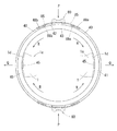
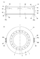
シールリング40は、転がり軸受21の軸方向一端側の軸受空間の側方開口D、及び、循環経路12の軸方向一端側の開口12cを覆うように、ハウジング11及び外輪1に取付けられる。転がり軸受21の軸方向一端側の軸受空間の側方開口Dは、外輪1と内輪2の軌道面1a,2aに沿って環状に形成されているので、それを覆うシールリング40も環状を成すものとなっている。   The seal ring 40 is attached to the housing 11 and the outer ring 1 so as to cover the side opening D of the bearing space on one end side in the axial direction of the rolling bearing 21 and the opening 12c on one end side in the axial direction of the circulation path 12. Since the side opening D of the bearing space on one end side in the axial direction of the rolling bearing 21 is formed in an annular shape along the raceway surfaces 1a and 2a of the outer ring 1 and the inner ring 2, the seal ring 40 covering the ring D also forms an annular shape. It has become a thing.

図1に示すように、シールリング40が転がり軸受21の端面に当接した状態とされ、他の転がり軸受22,23や間座5,6,7等とともにハウジング11内に収容される。   As shown in FIG. 1, the seal ring 40 is brought into contact with the end face of the rolling bearing 21 and is housed in the housing 11 together with the other rolling bearings 22 and 23 and spacers 5, 6, and 7.

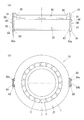
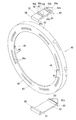
シールリング40は、図9に示すように、その筒軸方向端面41が、外輪1の軸方向一端側の端面1dに当接する円筒状部材からなる円筒部42と、円筒部42の筒軸方向一端部から内径側に向かって立ち上がる壁部43とを備える。   As shown in FIG. 9, the seal ring 40 has a cylindrical axial portion 42 whose cylindrical axial end surface 41 is in contact with the end surface 1 d on the axial end of the outer ring 1, and the cylindrical axial direction of the cylindrical portion 42. A wall 43 that rises from the one end toward the inner diameter side.

壁部43には、フィルタ46が設けられている。フィルタ46は、貫通穴からなるフィルタ孔46aの集合によって、転がり軸受21,22の軸受空間からの異物の通過を阻止し、潤滑油の通過は許容されるものである。このとき、フィルタ孔46aの内径は、少量あれば、作動機構部30側へ侵入しても影響がない程度の異物の通過は許容されるよう、適宜の寸法に設定される。   A filter 46 is provided on the wall 43. The filter 46 prevents foreign substances from passing through the bearing space of the rolling bearings 21 and 22 by the assembly of the filter holes 46a including through holes, and allows the passage of lubricating oil. At this time, if the inner diameter of the filter hole 46a is small, the filter hole 46a is set to an appropriate size so as to allow the passage of foreign matter to the extent that it does not affect even if it enters the operating mechanism 30 side.

この実施形態では、シールリング40は合成樹脂の成形品からなるものとしている。また、シールリング40は、転がり軸受21の軸受空間の側方開口Dに沿う円環状を成し、その円環の周方向に沿って分割された複数の分割シール部材40’が、連結片80によって円環状に接続された連結体である。周方向に隣り合う分割シール部材40’同士は、連結片80により接続される。連結片80も、合成樹脂の成形品からなるものとしている。   In this embodiment, the seal ring 40 is made of a molded product of synthetic resin. Further, the seal ring 40 forms an annular shape along the side opening D of the bearing space of the rolling bearing 21, and a plurality of divided seal members 40 ′ divided along the circumferential direction of the annular ring are connected pieces 80. It is the coupling body connected by the annular | circular shape by. The split seal members 40 ′ adjacent in the circumferential direction are connected by a connecting piece 80. The connecting piece 80 is also made of a synthetic resin molded product.

この実施形態では、中心角180°を成す2つの分割シール部材40’で円環状のシールリング40を構成しているので、連結片80は、シールリング40の上部と下部の2箇所に位置している。   In this embodiment, since the annular seal ring 40 is constituted by two divided seal members 40 ′ having a central angle of 180 °, the connecting piece 80 is located at two locations, the upper portion and the lower portion of the seal ring 40. ing.

さらに、シールリング40が、中心角180°の分割シール部材40’を二つ用いた2分割構成だけでなく、例えば、中心角90°の分割シール部材40’を四つ用いることで円環状のシールリング40を構成してもよいし、中心角60°の分割シール部材40’を六つ用いることで円環状のシールリング40を構成してもよい。   Furthermore, the seal ring 40 is not limited to a two-divided configuration using two split seal members 40 ′ having a central angle of 180 °, but, for example, by using four split seal members 40 ′ having a central angle of 90 °, The seal ring 40 may be configured, or the annular seal ring 40 may be configured by using six divided seal members 40 ′ having a central angle of 60 °.

また、この実施形態では、シールリング40は、壁部43のフィルタ46を、シールリング40の本体に一体に形成しているが、壁部43のフィルタ46を、シールリング40の本体の部材とは別部材として、その別部材をシールリング40の本体に、嵌め込み固定、埋め込み固定、接着等の種々の手段で固定するようにしてもよい。   In this embodiment, the seal ring 40 integrally forms the filter 46 of the wall portion 43 with the main body of the seal ring 40, but the filter 46 of the wall portion 43 is connected to the main body member of the seal ring 40. As another member, the separate member may be fixed to the main body of the seal ring 40 by various means such as fitting and fixing, embedding and adhesion.

シールリング40や連結片80の素材としては、樹脂以外にも、金属、ゴム等の他の素材を採用してもよい。フィルタ46をシールリング40とは別部材とする場合も、フィルタ46の素材として、樹脂、金属、ゴム等の他の素材を用いることができる。   As a material for the seal ring 40 and the connecting piece 80, other materials such as metal and rubber may be employed in addition to the resin. Even when the filter 46 is a separate member from the seal ring 40, other materials such as resin, metal, and rubber can be used as the material of the filter 46.

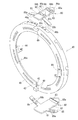
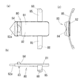
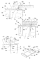
また、連結片80には、シールリング40の円筒部42の外周面に当接する基部81から、転がり軸受21側へ向かって軸方向へ伸びる軸方向部材82が設けられている。   Further, the connecting piece 80 is provided with an axial member 82 extending in the axial direction from the base portion 81 contacting the outer peripheral surface of the cylindrical portion 42 of the seal ring 40 toward the rolling bearing 21 side.

軸方向部材82は、ハウジング11の内径面と外輪1の外径面との間を通って転がり軸受21側へ伸びて、その軸方向部材82が軌道輪や間座等の軸受部材に係合することにより、シールリング40はハウジング11及び外輪1に固定される。   The axial member 82 extends between the inner diameter surface of the housing 11 and the outer diameter surface of the outer ring 1 and extends toward the rolling bearing 21, and the axial member 82 engages with a bearing member such as a bearing ring or a spacer. Thus, the seal ring 40 is fixed to the housing 11 and the outer ring 1.

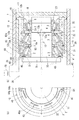
この実施形態では、軸方向部材82は、循環経路12の軸方向潤滑経路12a内を通って軸方向一端側から他端側へ向かって伸びており、その軸方向部材82の先端82aは先細りの形状となっている。このため、ハウジング11内への挿入がスムーズである。また、軸方向部材82の先端寄りには、内径側へ向かって伸びる内径側突出部83を備えている。軸方向潤滑経路12aは、ハウジング11の内径面と外輪1の外径面との間に軸方向に沿って配置される潤滑油用の油路である。   In this embodiment, the axial member 82 extends from the axial direction one end side to the other end side through the axial lubrication path 12a of the circulation path 12, and the distal end 82a of the axial direction member 82 is tapered. It has a shape. For this reason, the insertion into the housing 11 is smooth. Further, an inner diameter side protruding portion 83 extending toward the inner diameter side is provided near the tip of the axial member 82. The axial lubrication path 12 a is an oil path for lubricating oil disposed along the axial direction between the inner diameter surface of the housing 11 and the outer diameter surface of the outer ring 1.

軸方向部材82は、外輪1の外径面に接触しつつ、内径側突出部83が軸受の軌道輪や間座に設けた抜け止め凹部50に入り込むことで、シールリング40の軸方向への移動が規制される。この実施形態では、抜け止め凹部50は、間座6の一端側端面6aと、転がり軸受21の外輪1の肩部、すなわち、外輪1の外径面と軸方向他端側の端面1bとの間の稜線部に形成された曲面状のアール部1cや面取り部とによって構成されている。   The axial member 82 is in contact with the outer diameter surface of the outer ring 1, and the inner diameter side protruding portion 83 enters the retaining recess 50 provided in the bearing ring or spacer of the bearing, whereby the axial direction of the seal ring 40 is increased. Movement is restricted. In this embodiment, the retaining recess 50 includes an end surface 6a on one end side of the spacer 6 and a shoulder portion of the outer ring 1 of the rolling bearing 21, that is, an outer diameter surface of the outer ring 1 and an end surface 1b on the other end side in the axial direction. It is comprised by the curved-shaped round part 1c and chamfering part formed in the ridgeline part between.

間座6は、外輪1の軸方向他端側に隣接して配置される隣接部材である。この隣接部材である間座6は、軸方向に隣り合う転がり軸受21,22の外輪1同士を、軸方向に位置決めする機能を有している。   The spacer 6 is an adjacent member disposed adjacent to the other end side in the axial direction of the outer ring 1. The spacer 6 that is an adjacent member has a function of positioning the outer rings 1 of the rolling bearings 21 and 22 adjacent in the axial direction in the axial direction.

また、軸方向潤滑経路12aの軸方向一端側の開口12cは、側面視円環状を成す転がり軸受21の軸受空間の側方開口Dよりも外径側に位置する。この実施形態では、循環経路12の軸方向潤滑経路12aは2本設けられており、周方向に沿って180°の間隔をおいて2箇所に開口12cを有しているが、この開口12cの数は、必要に応じて増減してもよい。   Further, the opening 12c on one end side in the axial direction of the axial lubrication path 12a is located on the outer diameter side with respect to the side opening D of the bearing space of the rolling bearing 21 having an annular shape in a side view. In this embodiment, two axial lubrication paths 12a of the circulation path 12 are provided and have openings 12c at two positions with an interval of 180 ° along the circumferential direction. The number may be increased or decreased as necessary.

連結片80は、循環経路12側へ突出し、循環経路12の内壁に当接する第一の外径側突出部84を備える。第一の外径側突出部84は、軸方向部材82の外面から外径側へ向かって立ち上がり、その外径面に凸部84aと凹部84b、及び、通油孔84cを備える。凸部84aは、循環経路12の内壁に当接して連結片80を支持し、凹部84bと循環経路12内面との隙間、及び、通油孔84cは、循環経路12から軸受空間外への潤滑油の通路となる。凹部84bと循環経路12の内面との隙間、通油孔84cの内径は、同じく、フィルタ46のメッシュサイズと同じか、そのメッシュサイズ以下に設定される。第一の外径側突出部84に複数の貫通孔やスリットを設けて、異物を捕捉するためのフィルタとすることもできる。   The connecting piece 80 includes a first outer diameter side protruding portion 84 that protrudes toward the circulation path 12 and abuts against the inner wall of the circulation path 12. The first outer diameter side protruding portion 84 rises from the outer surface of the axial member 82 toward the outer diameter side, and includes a convex portion 84a, a concave portion 84b, and an oil passage hole 84c on the outer diameter surface. The convex portion 84a contacts the inner wall of the circulation path 12 to support the connecting piece 80, and the gap between the concave portion 84b and the inner surface of the circulation path 12 and the oil passage hole 84c are lubricated from the circulation path 12 to the outside of the bearing space. It becomes an oil passage. The clearance between the recess 84b and the inner surface of the circulation path 12 and the inner diameter of the oil passage hole 84c are set to be equal to or smaller than the mesh size of the filter 46. A plurality of through holes and slits may be provided in the first outer diameter side protruding portion 84 to provide a filter for capturing foreign matter.

また、連結片80は、第一の外径側突出部84よりも軸方向一端側に、同じく循環経路12側へ突出し、循環経路12の内壁に当接する第二の外径側突出部90を備える。第二の外径側突出部90は、軸方向部材82の外面から外径側へ向かって立ち上がり、その外径面に凸部90aと凹部90b、及び、通油孔90cを備える。凸部90aは、循環経路12の内壁に当接して連結片80を支持し、凹部90bと循環経路12内面との隙間、及び、通油孔90cは、循環経路12から軸受空間外への潤滑油の通路となる。凹部90bと循環経路12の内面との隙間、通油孔90cの内径は、同じく、フィルタ46のメッシュサイズと同じか、そのメッシュサイズ以下に設定される。第二の外径側突出部90に複数の貫通孔やスリットを設けて、異物を捕捉するためのフィルタとすることもできる。   Further, the connecting piece 80 has a second outer-diameter-side protruding portion 90 that protrudes toward the circulation path 12 on the one end side in the axial direction from the first outer-diameter-side protrusion 84 and contacts the inner wall of the circulation path 12. Prepare. The second outer diameter side protruding portion 90 rises from the outer surface of the axial member 82 toward the outer diameter side, and includes a convex portion 90a, a concave portion 90b, and an oil passage hole 90c on the outer diameter surface. The convex portion 90a contacts the inner wall of the circulation path 12 to support the connecting piece 80, and the gap between the concave portion 90b and the inner surface of the circulation path 12 and the oil passage hole 90c are lubricated from the circulation path 12 to the outside of the bearing space. It becomes an oil passage. The clearance between the recess 90b and the inner surface of the circulation path 12 and the inner diameter of the oil passage hole 90c are set to be the same as or smaller than the mesh size of the filter 46. A plurality of through holes and slits may be provided in the second outer diameter side protruding portion 90 to provide a filter for capturing foreign matter.

また、軸方向部材82、第一の外径側突出部84及び第二の外径側突出部90は、循環経路12内に入り込んで連結片80ががたつきなく固定されるよう、その幅(転がり軸受の周方向への幅)は循環経路12の幅(同じく転がり軸受の周方向への幅)と合致している。これにより、シールリング40は、ハウジング11及び外輪1に対して回り止めされる。すなわち、軸方向部材82、第一の外径側突出部84及び第二の外径側突出部90は、シールリング40の回り止め手段として機能している。   Further, the axial direction member 82, the first outer diameter side protruding portion 84, and the second outer diameter side protruding portion 90 have their widths so as to enter the circulation path 12 and fix the connecting piece 80 without rattling. The (width in the circumferential direction of the rolling bearing) matches the width of the circulation path 12 (also in the circumferential direction of the rolling bearing). Thereby, the seal ring 40 is prevented from rotating with respect to the housing 11 and the outer ring 1. That is, the axial member 82, the first outer diameter side protruding portion 84, and the second outer diameter side protruding portion 90 function as a detent means for the seal ring 40.

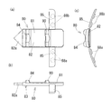
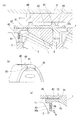
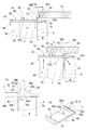
連結片80には、図5に示すように、基部81から周方向両側へ伸びる対の支え部85が設けられている。支え部85は、シールリング40の外径面に沿う円筒面状の部材である。各支え部85には、内径側へ突出する係止凸部88が設けられている。この係止凸部88が、周方向に隣り合う分割シール部材40’の端部にそれぞれ設けられた係止孔48に入り込むことで、連結片80は、周方向に隣り合う分割シール部材40’の端部同士を接続する。これにより、分割シール部材40’は円環状の連結体に構成される。   As shown in FIG. 5, the connecting piece 80 is provided with a pair of support portions 85 extending from the base portion 81 to both sides in the circumferential direction. The support portion 85 is a cylindrical surface member along the outer diameter surface of the seal ring 40. Each support portion 85 is provided with a locking projection 88 that protrudes toward the inner diameter side. The engaging protrusions 88 enter the engaging holes 48 provided at the end portions of the divided seal members 40 ′ adjacent in the circumferential direction, so that the connecting piece 80 is divided into the divided seal members 40 ′ adjacent in the circumferential direction. Connect the ends of each other. Thereby, the division | segmentation sealing member 40 'is comprised by the annular connection body.

また、分割シール部材40’の端部同士は、図6に示すように、壁部43に設けられ互いに対向するカギ状部47a,47bが噛み合っているので、その接続がより強固となっている。   Further, as shown in FIG. 6, the end portions of the split seal member 40 ′ are engaged with the key-like portions 47 a and 47 b provided on the wall portion 43 and facing each other, so that the connection is further strengthened. .

また、シールリング40の壁部43の内径側端部は、内輪2の大つば外径面にわずかな隙間wを介して対向して、壁部43と内輪2との間に隙間(最後すきま)wを有するラビリンスシール構造を形成している。この隙間では、潤滑油は通過が許容されるが、その隙間wの寸法を超える異物の通過は阻止される。壁部43の内径側端部と内輪2の大つば外径面との隙間wは、フィルタ46のメッシュサイズと同じか、そのメッシュサイズ以下に設定される。隙間wは、図4に示すように、シールリング40の内径面に設けた凸部44によって、所定の隙間w1よりも縮小しないように設定されている。図中の符号w2は、シールリング40の軸方向に対する凸部44の幅、符号w3は、シールリング40の周方向に対する凸部44の幅である。   Further, the inner diameter side end of the wall 43 of the seal ring 40 faces the outer surface of the large collar of the inner ring 2 with a slight gap w, and a gap (final clearance) is formed between the wall 43 and the inner ring 2. ) Forming a labyrinth seal structure having w. In this gap, the lubricating oil is allowed to pass, but the passage of foreign matter exceeding the size of the gap w is blocked. The gap w between the inner diameter side end of the wall 43 and the outer diameter surface of the large collar of the inner ring 2 is set to be the same as or smaller than the mesh size of the filter 46. As shown in FIG. 4, the gap w is set so as not to be smaller than the predetermined gap w <b> 1 by the convex portion 44 provided on the inner diameter surface of the seal ring 40. In the drawing, the symbol w2 is the width of the convex portion 44 with respect to the axial direction of the seal ring 40, and the symbol w3 is the width of the convex portion 44 with respect to the circumferential direction of the seal ring 40.

この実施形態では、連結片80と分割シール部材40’は、周方向に隣り合う分割シール部材40’同士の接続部の屈曲(折れ点の発生)を規制する折れ防止手段を備えている。分割シール部材40’同士の接続部が屈曲すると、それぞれの分割シール部材40’の軸方向端面の面方向が互いに異なる方向となり、シールリング40の端面と外輪1の端面1dとの間に隙間を生じるので、このような折れ防止手段が有効である。   In this embodiment, the connecting piece 80 and the divided seal member 40 ′ are provided with a fold prevention means for restricting the bending (generation of fold points) of the connecting portion between the divided seal members 40 ′ adjacent in the circumferential direction. When the connecting portions of the divided seal members 40 ′ are bent, the surface directions of the axial end surfaces of the divided seal members 40 ′ are different from each other, and a gap is formed between the end surface of the seal ring 40 and the end surface 1d of the outer ring 1. Such a breakage prevention means is effective.

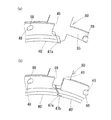
図6(a)(b)に示す例では、折れ防止手段として、周方向に隣り合う分割シール部材40’のそれぞれと連結片80とが、互いに、複数の係止凸部88(88a、88a;88b、88b)とそれに対応する数の係止孔48(48a、48a;48b、48b)とが係止することで接続されている。ここでは、並列する二つの係止凸部88が、対応する二つの係止孔48にそれぞれぴったりと入り込んで、連結片80と分割シール部材40’との間に相対回転やがたつき等が生じにくい状態となっている。特に、周方向に沿って複数の係止凸部88と、それに対応する複数の係止孔48を設けたことにより、分割シール部材40’同士の接続が、強固なものとなって、接続部の屈曲を防止している。このとき、係止凸部88の幅(シールリング40の軸方向に対する幅)と、係止孔48の幅(シールリング40の軸方向に対する幅)とは等しいことが望ましい。   In the example shown in FIGS. 6 (a) and 6 (b), each of the split seal members 40 ′ adjacent to each other in the circumferential direction and the connecting piece 80 serve as a break prevention means, and a plurality of locking projections 88 (88a, 88a) are mutually connected. 88b, 88b) and the corresponding number of locking holes 48 (48a, 48a; 48b, 48b) are connected by locking. Here, the two locking projections 88 arranged in parallel fit into the corresponding two locking holes 48, respectively, and relative rotation, rattling, etc. occur between the connecting piece 80 and the divided seal member 40 ′. It is difficult to occur. In particular, by providing a plurality of locking projections 88 and a plurality of locking holes 48 corresponding thereto in the circumferential direction, the connection between the divided seal members 40 'becomes strong, and the connection portion Prevents bending. At this time, it is desirable that the width of the locking projection 88 (width with respect to the axial direction of the seal ring 40) and the width of the locking hole 48 (width with respect to the axial direction of the seal ring 40) are equal.

なお、複数の係止凸部88と、それに対応する複数の係止孔48は、それぞれ軸方向に並列するように配置することもできる。   In addition, the some latching convex part 88 and the some latching hole 48 corresponding to it can also be arrange | positioned so that it may mutually parallel in an axial direction.

また、図6(a)(b)に示す例では、係止凸部88及び係止孔48は、それぞれ断面円形であるが、これらを非円形の断面を有するものとしてもよい。   Moreover, in the example shown to Fig.6 (a) (b), although the latching convex part 88 and the latching hole 48 are each circular in cross section, they are good also as having a non-circular cross section.

また、折れ防止手段は、周方向に隣り合う分割シール部材40’のうち少なくとも一方と連結片80との間に設けられていれば、シールリング40の軸方向端面と外輪1の端面1dとの間の隙間発生の防止に寄与し得るが、周方向に隣り合う分割シール部材40’のそれぞれと、連結片80との間に設けられていることが望ましい。   Further, if the break prevention means is provided between at least one of the circumferentially adjacent divided seal members 40 ′ and the connecting piece 80, the axial end surface of the seal ring 40 and the end surface 1 d of the outer ring 1 are provided. Although it can contribute to the prevention of gaps between them, it is desirable that the gap is provided between each of the divided seal members 40 ′ adjacent in the circumferential direction and the connecting piece 80.

図6(c)に示すように、係止凸部88の先端には、抜け止め凸部88cが設けられている。抜け止め凸部88cは係止孔48の縁に係合して、係止凸部88が係止孔48から抜け出すことを防止する抜け止め機能を発揮している。   As shown in FIG. 6C, a retaining projection 88 c is provided at the tip of the latching projection 88. The retaining protrusion 88 c engages with the edge of the locking hole 48 and exhibits a retaining function that prevents the locking protrusion 88 from slipping out of the locking hole 48.

また、分割シール部材40’と連結片80との接続位置を周方向に沿って可変とすることにより、複数の分割シール部材40’の接続によって構成されるシールリング40の径を、調整可能とできる。図7の例では、係止凸部88が入り込む係止孔48を、周方向に沿って設定された複数の箇所から任意に選択できるようにしている。   Further, by making the connection position of the divided seal member 40 ′ and the connecting piece 80 variable along the circumferential direction, the diameter of the seal ring 40 configured by connecting the plurality of divided seal members 40 ′ can be adjusted. it can. In the example of FIG. 7, the locking hole 48 into which the locking projection 88 enters can be arbitrarily selected from a plurality of locations set along the circumferential direction.

図7(a)(b)の例では、分割シール部材40’の端部から遠い側の係止孔48を利用することにより隙間w1を大きくし、相対的にシーリング40の径を大きく設定しており、図7(c)(d)の例では、分割シール部材40’の端部に近い側の係止孔48を利用することにより隙間w2を小さくし、相対的にシールリング40の径を小さく設定している。   In the example of FIGS. 7A and 7B, the gap w1 is increased by using the locking hole 48 on the side far from the end of the divided seal member 40 ′, and the diameter of the ceiling 40 is set relatively large. In the example of FIGS. 7C and 7D, the gap w2 is reduced by using the locking hole 48 on the side close to the end of the divided seal member 40 ′, and the diameter of the seal ring 40 is relatively set. Is set smaller.

また、この図7に示す例では、係止孔48を周方向に伸びる長孔とすることによって、係止凸部88が、係止孔48内で長孔の長さ方向に沿って移動できるようになっている。具体的には、係止凸部88が断面円形であるのに対し、係止孔48の形状は、シールリング40の周方向に沿って等幅で伸びて、その両端の閉塞縁を半円状とした長孔形状となっている。このため、係止凸部88が係止孔48内を長孔の長手方向に沿って移動することで、連結片80は、周方向に隣り合う分割シール部材40’の端部同士を周方向へスライド自在に接続することができる。これにより、温度上昇によってシールリング40が熱膨張した際に、あるいは、温度下降によりシールリング40が収縮した際に、連結片80で接続された分割シール部材40’の端部間の距離が変化して、その膨張、収縮に対応することができる。   Further, in the example shown in FIG. 7, by making the locking hole 48 a long hole extending in the circumferential direction, the locking projection 88 can move in the locking hole 48 along the length direction of the long hole. It is like that. Specifically, while the locking projection 88 has a circular cross section, the shape of the locking hole 48 extends at an equal width along the circumferential direction of the seal ring 40, and the closed edges at both ends thereof are semicircular. It has a long hole shape. For this reason, the engaging protrusion 88 moves in the engaging hole 48 along the longitudinal direction of the long hole, so that the connecting piece 80 connects the ends of the divided seal members 40 ′ adjacent to each other in the circumferential direction. Can be slidably connected. Thereby, when the seal ring 40 is thermally expanded due to a temperature rise or when the seal ring 40 is contracted due to a temperature drop, the distance between the end portions of the divided seal members 40 ′ connected by the connecting piece 80 is changed. Thus, the expansion and contraction can be dealt with.

図8(a)に示す例では、前述の例と同じく、周方向に隣り合う分割シール部材40’のそれぞれと連結片80とが、互いに、複数の係止凸部88が、それに対応する数の係止孔48に係止することで接続されて、折れ防止手段を構成している。   In the example shown in FIG. 8A, as in the previous example, each of the circumferentially adjacent divided seal members 40 ′ and the connecting piece 80 are each a plurality of locking projections 88, and the number corresponding to that is the number. It is connected by being locked in the locking hole 48 to constitute a break prevention means.

ここでは、分割シール部材40’と連結片80との接続に関わる二つの係止凸部88のうち、分割シール部材40’の端部から遠い側の係止凸部88は、係止孔48の外輪1側の内壁に当接し、その反対側の内壁との間には隙間を介在している。また、分割シール部材40’の端部に近い側の係止凸部88は、係止孔48の外輪1側の内壁との間に隙間を介在し、その反対側の内壁には当接している。このような構成により、係止凸部88の幅(シールリング40の軸方向に対する幅)を、係止孔48の幅(シールリング40の軸方向に対する幅)よりも小さくして、両者の円滑な係止及び係止の解除を確保しつつ、且つ、図中に矢印xで示す方向へのシールリング40の屈曲を防止できる。   Here, of the two locking projections 88 related to the connection between the divided seal member 40 ′ and the connecting piece 80, the locking projection 88 on the side far from the end of the divided seal member 40 ′ is the locking hole 48. Is in contact with the inner wall on the outer ring 1 side, and a gap is interposed between the inner wall on the opposite side. Further, the locking projection 88 on the side close to the end of the split seal member 40 ′ has a gap between the locking hole 48 and the inner wall on the outer ring 1 side, and abuts against the opposite inner wall. Yes. With such a configuration, the width of the locking projection 88 (the width of the seal ring 40 with respect to the axial direction) is made smaller than the width of the locking hole 48 (the width of the seal ring 40 with respect to the axial direction). It is possible to prevent the seal ring 40 from being bent in the direction indicated by the arrow x in the drawing while ensuring proper locking and unlocking.

つまり、分割シール部材40’同士の接続部付近は、連結片80の抜け止め機能によって、外輪1に拘束されているので、連結片80から周方向に沿って離れた部分が、図8(a)に矢印xに示すように、外輪1の端面1dから離脱することを防止することが有効である。   That is, since the vicinity of the connecting portion between the split seal members 40 ′ is restrained by the outer ring 1 by the function of preventing the connecting piece 80 from coming off, a portion away from the connecting piece 80 in the circumferential direction is shown in FIG. It is effective to prevent the outer ring 1 from detaching from the end surface 1d as indicated by an arrow x in FIG.

図8(b)に示す例では、周方向に隣り合う分割シール部材40’のそれぞれと連結片80とが、互いに、一つの係止凸部88とそれに対応する一つの係止孔48とが係止することで接続されている。ここで、係止凸部88と係止孔48の断面形状を非円形とすることにより折れ防止手段を構成し、図8(b)に矢印xで示す方向へのシールリング40の屈曲を防止している。ここでは、係止凸部88と係止孔48の断面形状を四角形としているが、五角形、六角形、楕円形など、種々の形状を採用できる。   In the example shown in FIG. 8B, each of the circumferentially adjacent divided seal members 40 ′ and the connecting piece 80 are formed by one locking projection 88 and one locking hole 48 corresponding thereto. It is connected by locking. Here, the cross-sectional shape of the locking projection 88 and the locking hole 48 is made non-circular to constitute a break prevention means, and the bending of the seal ring 40 in the direction indicated by the arrow x in FIG. 8B is prevented. doing. Here, the cross-sectional shapes of the locking projection 88 and the locking hole 48 are rectangular, but various shapes such as a pentagon, a hexagon, and an ellipse can be employed.

図8(c)(d)は、図7の例における長孔状の係止孔48の長さを、シールリング40の周方向に沿って長くしたものである。このため、一つの長孔状の係止孔48に、周方向に並列する複数の係止凸部88が入り込んで係止された態様となっている。   8C and 8D, the length of the long hole-like locking hole 48 in the example of FIG. 7 is increased along the circumferential direction of the seal ring 40. For this reason, it has a mode in which a plurality of locking projections 88 arranged in parallel in the circumferential direction are inserted into and locked in one long hole-shaped locking hole 48.

以上のように、係止凸部88は、周方向に隣り合う分割シール部材40’のそれぞれに対して少なくとも一つあればよいが、これを二つ、あるいは三つ以上の複数としてもよい。このとき、折れ防止手段は、分割シール部材40’のそれぞれに対して係止凸部88が二つ以上あれば、接続部における屈曲を防止する効果を発揮できる。また、折れ防止手段は、分割シール部材40’のそれぞれに対して係止凸部88が一つであれば、その係止凸部88の断面形状を非円形とし、係止孔48の断面形状も係止凸部88がぴったりと嵌る同形状とすることにより、分割シール部材40’と連結片80との相対回転を規制し、接続部における屈曲を防止する効果を発揮できる。   As described above, at least one locking protrusion 88 may be provided for each of the divided seal members 40 ′ adjacent in the circumferential direction, but two or more than two may be provided. At this time, the bend prevention means can exhibit the effect of preventing the bending at the connecting portion if there are two or more locking projections 88 for each of the divided seal members 40 ′. Further, if the folding preventing means has one locking projection 88 for each of the divided seal members 40 ′, the sectional shape of the locking projection 88 is non-circular, and the sectional shape of the locking hole 48. In addition, by adopting the same shape in which the locking projection 88 fits snugly, the relative rotation between the divided seal member 40 ′ and the connecting piece 80 can be restricted, and the effect of preventing bending at the connecting portion can be exhibited.

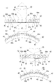
図9に示す例では、図9(a)は、連結片80が存在する方位におけるシールリング40等の縦断面を示している。連結片80は、周方向に沿って複数(この例では、180°ごとに合計2箇所)備えられている。そして、周方向に隣り合う連結片80間において、シールリング40には、図9(b)に示すように、外輪1に対するシールリング40の外径側への移動を規制する外輪係止凸部45が備えられている。外輪係止凸部45は、隣り合う連結片80間の中央に設けられることが望ましい。外輪係止凸部45は、図9(c)に示すように、外輪1の軌道面1aと端面1dとの間のあご部に係止されて、シールリング40の外径側への移動を規制する。   In the example shown in FIG. 9, FIG. 9A shows a longitudinal section of the seal ring 40 and the like in the direction in which the connecting piece 80 exists. A plurality of connecting pieces 80 are provided along the circumferential direction (in this example, a total of two places every 180 °). And between the connection pieces 80 adjacent to the circumferential direction, as shown in FIG. 9B, the seal ring 40 has an outer ring locking projection that restricts the movement of the seal ring 40 relative to the outer ring 1 to the outer diameter side. 45 is provided. The outer ring locking projection 45 is preferably provided at the center between the adjacent connecting pieces 80. As shown in FIG. 9 (c), the outer ring locking convex portion 45 is locked to the jaw portion between the raceway surface 1 a and the end surface 1 d of the outer ring 1 to move the seal ring 40 toward the outer diameter side. regulate.

図10に示すように、ハウジング11の鉛直方向上方側と鉛直方向下方側に連結片80が位置している。ここで、部材の温度上昇により、シールリング40が外径方向に熱膨張しようとした際を想定する。この外径方向での熱膨張は、図中に矢印Pで示すように、鉛直方向上方側と下方側から拘束される。連結片80の第一の外径側突出部84、第二の外径側突出部90が、ハウジング11に当接しているからである。すなわち、連結片80は、ハウジング11に対するシールリング40の外径側への移動を規制している。   As shown in FIG. 10, connecting pieces 80 are positioned on the upper side in the vertical direction and the lower side in the vertical direction of the housing 11. Here, it is assumed that the seal ring 40 is about to thermally expand in the outer diameter direction due to the temperature rise of the member. This thermal expansion in the outer diameter direction is restrained from the upper side and the lower side in the vertical direction as indicated by an arrow P in the drawing. This is because the first outer diameter side protruding portion 84 and the second outer diameter side protruding portion 90 of the connecting piece 80 are in contact with the housing 11. That is, the connecting piece 80 restricts the movement of the seal ring 40 relative to the housing 11 toward the outer diameter side.

このため、シールリング40の熱膨張は、図10の矢印Rの方向へ周方向に作用していく。したがって、周方向に隣り合う連結片80間では、矢印Qに示すように、シールリング40が外径方向へ拡がろうとする力が作用する。このとき、外輪係止凸部45は、ハウジング11に対するシールリング40の外径側への移動を規制することができる。これにより、シールリング40の内径側に設定された隙間wが適正に確保される。   For this reason, the thermal expansion of the seal ring 40 acts in the circumferential direction in the direction of arrow R in FIG. Therefore, between the connecting pieces 80 adjacent to each other in the circumferential direction, as indicated by an arrow Q, a force acts to expand the seal ring 40 in the outer diameter direction. At this time, the outer ring locking projection 45 can regulate the movement of the seal ring 40 relative to the housing 11 to the outer diameter side. Thereby, the gap w set on the inner diameter side of the seal ring 40 is appropriately secured.

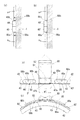
図11は、連結片80の変形例を示すものである。この変形例の連結片80は、円筒部42の外径面に当接する基部81の軸方向一端に、内径側へ突出する係止片89を備えている。係止片89が円筒部42の軸方向一端側の端面に当接して、連結片80はシールリング40に固定される。このため支え部85の設置は省略されている。また、シールリング40は、一体の部材として円環状に成形されたものである。   FIG. 11 shows a modified example of the connecting piece 80. The connecting piece 80 of this modification includes a locking piece 89 that protrudes toward the inner diameter side at one end in the axial direction of the base 81 that contacts the outer diameter surface of the cylindrical portion 42. The locking piece 89 comes into contact with the end face on the one end side in the axial direction of the cylindrical portion 42, and the connecting piece 80 is fixed to the seal ring 40. For this reason, installation of the support part 85 is abbreviate | omitted. The seal ring 40 is formed in an annular shape as an integral member.

ここで、連結片80の抜け止め構造について説明する。図12は、支え部85を省略して係止片89を備えた図11の連結片80を例に、この発明の作用を説明しているが、連結片80は、図1〜図6に示すような支え部85を備えた態様であっても、同様の効果を発揮できる。   Here, the retaining structure of the connecting piece 80 will be described. FIG. 12 illustrates the operation of the present invention by taking the connecting piece 80 of FIG. 11 provided with the locking piece 89 without the support portion 85 as an example. The connecting piece 80 is shown in FIGS. Even if it is the aspect provided with the support part 85 as shown, the same effect can be exhibited.

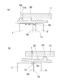
図12(a)に示すように、連結片80は、軸方向部材82に設けられる外径側突出部84が、内径側突出部83が当接する抜け止め凹部50の軸方向他端側の端面6aよりも、さらに軸方向他端側に位置している。すなわち、外径側突出部84は、外輪1の外径面と端面1bとの間の稜線部に形成された曲面状のアール部1cよりも、さらに軸方向他端側に位置している。   As shown in FIG. 12A, the connecting piece 80 has an end surface on the other end side in the axial direction of the retaining recess 50 with which the outer diameter side protruding portion 84 provided on the axial member 82 contacts the inner diameter side protruding portion 83. It is located further on the other axial end side than 6a. That is, the outer diameter side protruding portion 84 is located further on the other end side in the axial direction than the curved rounded portion 1c formed on the ridge line portion between the outer diameter surface of the outer ring 1 and the end surface 1b.

これにより、シールリング40と一体の連結片80を軸方向潤滑経路12a内に挿入する際には、軸方向部材82は、外径側突出部84の軸方向他端側の縁、すなわち、外径側突出部84の外径面84bと他端側の端面84aとの間の稜線部に設けた面取り部84cが、ハウジング11の端面11aの内径側縁に当たることによって、図12(a)の矢印aに示すように、ハウジング11側から内径側へ向かって押圧される。内径側突出部83と外径側突出部84とは軸方向に重複した範囲に設定されているので、この矢印aの押圧により、内径側突出部83は、アール部1cの傾斜面に沿ってスムーズに凹部50へ誘導される。   As a result, when the connecting piece 80 integrated with the seal ring 40 is inserted into the axial lubrication path 12a, the axial member 82 is the edge on the other axial end side of the outer diameter side protruding portion 84, that is, the outer side. The chamfered portion 84c provided in the ridge line portion between the outer diameter surface 84b of the radial side protruding portion 84 and the end surface 84a on the other end side abuts on the inner diameter side edge of the end surface 11a of the housing 11, so that FIG. As shown by the arrow a, it is pressed from the housing 11 side toward the inner diameter side. Since the inner diameter side projecting portion 83 and the outer diameter side projecting portion 84 are set to overlap with each other in the axial direction, the inner diameter side projecting portion 83 is moved along the inclined surface of the rounded portion 1c by pressing the arrow a. It is smoothly guided to the recess 50.

つづいて、シールリング40と連結片80とを軸方向他端側へ押し込むと、図12(b)に矢印cで示すように、連結片80は、ハウジング11側から内径側への押圧により、内径側突出部83が抜け止め凹部50内に深く入り込む。   Subsequently, when the seal ring 40 and the connecting piece 80 are pushed into the other end side in the axial direction, the connecting piece 80 is pressed from the housing 11 side to the inner diameter side as shown by an arrow c in FIG. The inner diameter side protruding portion 83 enters deeply into the retaining recess 50.

このとき、外径側突出部84がアール部1cよりも軸方向他端側にあるので、内径側突出部83は、アール部1cの傾斜面を下るように軸方向他端側へ引っ張られる(図12(b)の矢印b参照)。内径側突出部83の軸方向一端側に向く面83b、及び、その内径側突出部83が当接する抜け止め凹部50の軸方向一端側の内壁(前記アール部1c)が、軸方向一端側から軸方向他端側へ向かって内径側へ傾斜しているので、このような作用が期待できる。   At this time, since the outer diameter side protruding portion 84 is located on the other end side in the axial direction from the rounded portion 1c, the inner diameter side protruding portion 83 is pulled toward the other end side in the axial direction so as to go down the inclined surface of the rounded portion 1c ( (See arrow b in FIG. 12B). A surface 83b facing the one end side in the axial direction of the inner diameter side protruding portion 83 and an inner wall (the rounded portion 1c) on one end side in the axial direction of the retaining recess 50 with which the inner diameter side protruding portion 83 abuts are formed from one end side in the axial direction. Since it is inclined toward the inner diameter side toward the other end side in the axial direction, such an action can be expected.

また、内径側突出部83が、アール部1cの傾斜面を下るように軸方向他端側へ引っ張られる(図12(b)の矢印b参照)ことにより、内径側突出部83の軸方向他端側の端面83aは、抜け止め凹部50の軸方向他端側の端面6aに面接触する。内径側突出部83の軸方向他端側の端面83aと、抜け止め凹部50の軸方向他端側の端面6aは、軸方向に直交する面方向を有する。これにより、連結片80は、抜け止め凹部50の軸方向他端側の端面6aによって軸方向へ位置決めされ、よりしっかりと固定されることになる。   Further, the inner diameter side protruding portion 83 is pulled toward the other end side in the axial direction so as to go down the inclined surface of the rounded portion 1c (see the arrow b in FIG. 12B), so that the axial direction of the inner diameter side protruding portion 83 and the like. The end surface 83 a on the end side is in surface contact with the end surface 6 a on the other end side in the axial direction of the retaining recess 50. An end surface 83a on the other end side in the axial direction of the inner diameter side protruding portion 83 and an end surface 6a on the other end side in the axial direction of the retaining recess 50 have a surface direction orthogonal to the axial direction. Thereby, the connecting piece 80 is positioned in the axial direction by the end surface 6a on the other end side in the axial direction of the retaining recess 50 and is more firmly fixed.

この外輪1の稜線部に設けられる曲面状のアール部1cによる効果は、外輪1の稜線部をこのアール部1cに代えて、稜線部の角を落とした面取り部とした場合にも、同様に発揮することができる。すなわち、内径側突出部83が当接する抜け止め凹部50の軸方向一端側の内壁は、軸方向一端側から軸方向他端側に向かって内径側へ傾斜していることが望ましい。   The effect of the curved rounded portion 1c provided on the ridgeline portion of the outer ring 1 is the same even when the ridgeline portion of the outer ring 1 is replaced with the rounded portion 1c and a chamfered portion with a corner of the ridgeline portion is dropped. It can be demonstrated. That is, it is desirable that the inner wall on one end side in the axial direction of the retaining recess 50 with which the inner diameter side protruding portion 83 abuts is inclined toward the inner diameter side from the one axial end side toward the other axial end side.

この点について、仮に、外径側突出部84が、抜け止め凹部50の軸方向他端側の端面6aよりも軸方向一端側にあると、図20(a)に矢印eで示すように、連結片80は、軸方向一端側へ引っ張られてしまうことになる。このため、外径側突出部84は、抜け止め凹部50の軸方向他端側の端面6aよりも軸方向他端側にあることが望ましい。   In this regard, if the outer-diameter-side protruding portion 84 is located on one end side in the axial direction with respect to the end surface 6a on the other end side in the axial direction of the retaining recess 50, as shown by an arrow e in FIG. The connecting piece 80 is pulled toward one end in the axial direction. For this reason, it is desirable that the outer diameter side protruding portion 84 is located on the other end side in the axial direction with respect to the end surface 6 a on the other end side in the axial direction of the retaining recess 50.

さらに、図12(c)に示すように、外径側突出部84と間座6とは、その軸方向位置が、図中の軸方向幅Lの範囲で重複して配置されている。間座6は、図中の符号Wの軸方向幅となっている。このため、外径側突出部84がハウジング11側から内径側へ向かって押圧される際に、その押圧力が、抜け止め凹部50に入り込む内径側突出部83に伝達されやすい。   Furthermore, as shown in FIG. 12C, the outer diameter side protruding portion 84 and the spacer 6 are disposed so that their axial positions overlap within the range of the axial width L in the drawing. The spacer 6 has an axial width of a symbol W in the drawing. For this reason, when the outer diameter side protruding portion 84 is pressed from the housing 11 side toward the inner diameter side, the pressing force is easily transmitted to the inner diameter side protruding portion 83 that enters the retaining recess 50.

この点について、仮に、外径側突出部84と間座6との軸方向位置が重複していないと、図20(b)に示すように、外径側突出部84がハウジング11側から内径側へ向かって押圧される際に、その押圧力が、軸方向部材82の先端82aが内径側へ傾く力になって逃げてしまい、内径側突出部83は、矢印fに示すように、抜け止め凹部50から抜け出してしまう。このため、外径側突出部84と間座6との軸方向位置は重複していることが望ましい。   In this regard, if the axial positions of the outer diameter side protruding portion 84 and the spacer 6 do not overlap, as shown in FIG. 20B, the outer diameter side protruding portion 84 moves from the housing 11 side to the inner diameter. When pressing toward the side, the pressing force causes the tip 82a of the axial member 82 to become a force that tilts toward the inner diameter side and escapes, and the inner diameter side protruding portion 83 is removed as shown by the arrow f. It will slip out of the stop recess 50. For this reason, it is desirable that the axial positions of the outer diameter side protruding portion 84 and the spacer 6 overlap.

また、外径側突出部84と内径側間座5との軸方向位置も、重複していることが望ましい。外径側突出部84がハウジング11側から内径側へ向かって押圧される際に、その押圧力が、抜け止め凹部50に入り込む内径側突出部83に伝達されやすいからである。   In addition, it is desirable that the axial positions of the outer diameter side protruding portion 84 and the inner diameter side spacer 5 also overlap. This is because when the outer diameter side protrusion 84 is pressed from the housing 11 side toward the inner diameter side, the pressing force is easily transmitted to the inner diameter side protrusion 83 that enters the retaining recess 50.

このような構成としたことにより、転がり軸受21,22,23の軸受空間からの潤滑油は、シールリング40に設けたフィルタ46の孔46aや、循環経路12内の孔や隙間、あるいは、壁部43の内径側端部と内輪2の大つば外径面との隙間を通過して、軸受空間外へ流出する。このため、作動機構部30、70の動作に影響が出るような大きな異物(金属からなる摩耗粉の他、特に剥離片等)は、作動機構部30、70側へは侵入しない。また、連結片80によって、シールリング40が外輪1にしっかりと固定されているので、シールリング40と外輪1等との間に、異物を流出させるような隙間が生じることを防止できる。   By adopting such a configuration, the lubricating oil from the bearing space of the rolling bearings 21, 22, 23 can be removed from the hole 46 a of the filter 46 provided in the seal ring 40, the hole or gap in the circulation path 12, or the wall. It passes through the gap between the inner diameter side end of the portion 43 and the outer diameter surface of the inner collar 2 and flows out of the bearing space. For this reason, large foreign matters (in particular, wear particles made of metal as well as peeling pieces) that affect the operation of the operating mechanism portions 30 and 70 do not enter the operating mechanism portions 30 and 70 side. Further, since the seal ring 40 is firmly fixed to the outer ring 1 by the connecting piece 80, it is possible to prevent a gap from flowing out foreign matter between the seal ring 40 and the outer ring 1 or the like.

なお、上記の実施形態では、抜け止め凹部50は、外輪1と間座6(隣接部材)との間に形成したが、この抜け止め凹部50を、外輪1の外径面や間座6の外径面に形成してもよい。また、転がり軸受21に隣接する別の転がり軸受22の外輪1を隣接部材として、その隣接部材の外径面に抜け止め凹部50を形成してもよい。   In the embodiment described above, the retaining recess 50 is formed between the outer ring 1 and the spacer 6 (adjacent member). However, the retaining recess 50 is formed on the outer diameter surface of the outer ring 1 or the spacer 6. You may form in an outer diameter surface. Alternatively, the outer ring 1 of another rolling bearing 22 adjacent to the rolling bearing 21 may be used as an adjacent member, and the retaining recess 50 may be formed on the outer diameter surface of the adjacent member.

また、連結片80の第一の外径側突出部84や第二の外径側突出部90における外径面84b,90bの表面粗さは、基部81や軸方向部材82の内径面82b、すなわち、連結片80と接触する外輪1の外径面1dの表面粗さよりも小さく(滑らかに)なっている。これにより、連結片80が抜けにくくなるという効果が期待できる。   Further, the surface roughness of the outer diameter surfaces 84b and 90b in the first outer diameter side protruding portion 84 and the second outer diameter side protruding portion 90 of the connecting piece 80 is the base portion 81 and the inner diameter surface 82b of the axial member 82, That is, it is smaller (smooth) than the surface roughness of the outer diameter surface 1 d of the outer ring 1 that contacts the connecting piece 80. Thereby, the effect that the connecting piece 80 becomes difficult to come off can be expected.

ここで、表面粗さを比較する基準として、例えば、JIS(日本工業規格)等に規定される中心線平均粗さ(算術平均粗さRa:表面の山すべてを均した中心線で示される数値)や、最大高さ粗さ(Rmax:表面の計測範囲内でもっとも高い山の高さ)、十点平均高さ(Rz:表面の計測範囲内で高い山から10点を抽出しその平均値を取った値)等の各種の基準、測定方法を採用することができる。   Here, as a reference for comparing the surface roughness, for example, centerline average roughness (arithmetic average roughness Ra: numerical value indicated by a centerline obtained by leveling all the surface peaks) defined in JIS (Japanese Industrial Standards) and the like. ), Maximum height roughness (Rmax: height of the highest peak in the surface measurement range), ten-point average height (Rz: average of 10 points extracted from the high peaks in the surface measurement range) Various standards and measurement methods such as (taken values) can be adopted.

また、例えば、図12(d)に示すように、連結片80の内径側突出部83の幅A+αが、基部81や軸方向部材82の幅Aよりも大きいものを採用することができる。すなわち、この変形例では、内径側突出部83の両端83c,83dは、基部81や軸方向部材82の幅方向両端縁82c,82dよりも外側に突出している。これにより、連結片80は周方向突出する凸部形状を有することとなり、その結果、軸方向潤滑経路12aの開口12cの幅よりも対向する周方向突出する凸部間の幅が大きくなり、軸受挿入時に、周方向突出する凸部がハウジング11の軸方向潤滑経路12でない部分に入り込むため、ハウジング11に内径側突出部83が入ったときより、軸連結片80は軸方向、また、径方向に動きが規制され、運転時に外れることがなくなる。   Further, for example, as shown in FIG. 12 (d), a width A + α of the inner diameter side protruding portion 83 of the connecting piece 80 can be larger than the width A of the base portion 81 or the axial member 82. . That is, in this modification, both ends 83c and 83d of the inner diameter side protruding portion 83 protrude outward from the widthwise both ends 82c and 82d of the base portion 81 and the axial member 82. As a result, the connecting piece 80 has a convex shape protruding in the circumferential direction. As a result, the width between the convex portions protruding in the circumferential direction is larger than the width of the opening 12c of the axial lubrication path 12a. Since the projecting portion protruding in the circumferential direction enters a portion of the housing 11 that is not the axial lubrication path 12 at the time of insertion, the shaft connecting piece 80 is axially or radially more than when the inner diameter side protruding portion 83 is inserted into the housing 11. The movement is restricted, and it will not come off during driving.

また、上記の各実施形態において、シールリング40に設けられるフィルタ46の孔46a周辺に、金属粉等の異物の付着を検出するセンサ部を備えてもよい。センサ部としては、例えば、対の電極間に異物が介在することにより、その異物が電極間を短絡した際の電気的出力の変化によって、異物の存在を検知する電気式センサを採用することができる。   Further, in each of the above-described embodiments, a sensor unit that detects adhesion of a foreign substance such as metal powder may be provided around the hole 46 a of the filter 46 provided in the seal ring 40. As the sensor unit, for example, it is possible to employ an electric sensor that detects the presence of a foreign substance by a change in electrical output when the foreign substance is short-circuited between the electrodes due to the presence of a foreign substance between a pair of electrodes. it can.

例えば、対の電極間に、フィルタ46の孔46aを通過できない大きさの金属からなる異物が付着することに伴って、その対の電極からケーブルを通じて接続された出力検出装置は、対の電極間の異物を介した導通によって、電気回路の電気的出力の変化を検出し、潤滑油に含まれる金属からなる異物の状態(含有量)を検知することができる。対の電極に接続されたケーブルは、基板を経由してハウジング11外に引き出されて、そのケーブルに接続された出力検出装置がいずれかの部分に設けられる。シールリング40外にケーブルを引き出すためのセンサ孔は、シールリング40の円筒部42や壁部43等に設けることができる。   For example, when a foreign object made of metal of a size that cannot pass through the hole 46a of the filter 46 adheres between the pair of electrodes, the output detection device connected through the cable from the pair of electrodes is connected between the pair of electrodes. The change in the electrical output of the electric circuit can be detected by the conduction through the foreign matter, and the state (content) of the foreign matter made of a metal contained in the lubricating oil can be detected. The cable connected to the pair of electrodes is drawn out of the housing 11 through the substrate, and an output detection device connected to the cable is provided in any part. A sensor hole for drawing the cable out of the seal ring 40 can be provided in the cylindrical portion 42 or the wall portion 43 of the seal ring 40.

図13〜図19に、この発明の第二の実施形態を示す。この実施形態は、前述の第一の実施形態における連結片80の第二の外径側突出部90を省略したものである。また、連結片80が備える係止凸部88を、一つの分割シール部材40’に対して一つとしている点で異なっている。   13 to 19 show a second embodiment of the present invention. In this embodiment, the second outer diameter side protruding portion 90 of the connecting piece 80 in the first embodiment is omitted. Moreover, it differs in that the locking projection 88 provided in the connecting piece 80 is one for each divided seal member 40 '.

このように、連結片80の外径側突出部を一つ、すなわち、外径側突出部を第一の外径側突出部84のみとした場合も、連結片80は、同じくシールリング40の回り止め機能、抜け止め機能、外径側への移動防止機能を発揮することができる。   Thus, even when the outer diameter side protruding portion of the connecting piece 80 is only one, that is, the outer diameter side protruding portion is only the first outer diameter side protruding portion 84, the connecting piece 80 is similarly formed of the seal ring 40. The anti-rotation function, the retaining function, and the function of preventing movement to the outer diameter side can be exhibited.

第一の実施形態における図1は、第二の実施形態の図13に対応する。以下、図2は図14に対応し、図3は図15に対応する。図4は、第二の外径側突出部90の有無に関する以外は、第一の実施形態と第二の実施形態とで共通である。図5は図16に対応し、図6は図17に対応し、図11は図18に対応する。図12と図19は、第二の外径側突出部90の有無に関する以外は、第一の実施形態と第二の実施形態とで共通の内容である。このため、詳細な説明は省略する。   FIG. 1 in the first embodiment corresponds to FIG. 13 in the second embodiment. 2 corresponds to FIG. 14 and FIG. 3 corresponds to FIG. FIG. 4 is common to the first embodiment and the second embodiment except for the presence / absence of the second outer diameter side protrusion 90. 5 corresponds to FIG. 16, FIG. 6 corresponds to FIG. 17, and FIG. 11 corresponds to FIG. FIG. 12 and FIG. 19 are the contents common to the first embodiment and the second embodiment except for the presence or absence of the second outer diameter side protruding portion 90. For this reason, detailed description is omitted.

これらの実施形態では、係止凸部88を連結片80に、係止孔48を分割シール部材40’に設けたが、これを逆にして、係止凸部88を分割シール部材40’に、係止孔48を連結片80に設けてもよい。   In these embodiments, the locking projection 88 is provided in the connecting piece 80 and the locking hole 48 is provided in the divided seal member 40 ′. The locking hole 48 may be provided in the connecting piece 80.

上記の実施形態では、シールリング40にフィルタ46を設けたが、フィルタ46を備えないシールリング40においても、この発明の内容を適用できる。また、分割シール部材40’や連結片80を用いた分割型のシールリング40以外にも、分割型ではない一体型の円環状のシールリング40においても、この発明の内容を適用できる。   In the above embodiment, the filter 46 is provided on the seal ring 40. However, the present invention can be applied to the seal ring 40 that does not include the filter 46. In addition to the split seal ring 40 using the split seal member 40 ′ and the connecting piece 80, the present invention can be applied to an integral annular seal ring 40 that is not a split type.

この発明のシール部材は、実施形態以外の各種の転がり軸受ユニットにも適用できる。さらに、そのシール部材を備えた転がり軸受ユニットは、オイルポンプ60以外の各種装置にも適用できる。特に、この発明の転がり軸受は、転がり軸受から発生する摩耗粉(鉄粉等)等の異物が、潤滑油の循環経路の途中にある作動機構部70に侵入することを防ぐ必要がある種々の装置に適用できる。   The seal member of the present invention can be applied to various rolling bearing units other than the embodiment. Further, the rolling bearing unit including the seal member can be applied to various devices other than the oil pump 60. In particular, the rolling bearing of the present invention requires various types of foreign materials such as wear powder (iron powder, etc.) generated from the rolling bearing to be prevented from entering the operating mechanism 70 in the middle of the lubricating oil circulation path. Applicable to equipment.

1 外輪(外側軌道輪)
1b 端面
1c アール部
2 内輪(内側軌道輪)
3 転動体
4 保持器
5,6,7 間座
6a 端面
8 押え部材
10 オイルポンプ装置
11 ハウジング
12,13 循環経路
20 軸受ユニット
21,22,23 転がり軸受
30 作動機構部
31 接続部材
32 軸部材
40 シールリング(シール部材)
40’ 分割シール部材
44 凸部
45 外輪係止凸部
46 フィルタ
50 抜け止め凹部
60 オイルポンプ
70 作動機構部
80 連結片
81 基部
82 軸方向部材
83 内径側突出部
84 外径側突出部
85 支え部
1 Outer ring (outer raceway)
1b End face 1c Round portion 2 Inner ring (Inner race)
DESCRIPTION OF SYMBOLS 3 Rolling body 4 Cage 5, 6, 7 Spacer 6a End surface 8 Holding member 10 Oil pump apparatus 11 Housing 12, 13 Circulation path 20 Bearing unit 21, 22, 23 Rolling bearing 30 Actuation mechanism part 31 Connection member 32 Shaft member 40 Seal ring (seal member)
40 'split seal member 44 convex portion 45 outer ring locking convex portion 46 filter 50 retaining recess 60 oil pump 70 operating mechanism portion 80 connecting piece 81 base portion 82 axial member 83 inner diameter side protruding portion 84 outer diameter side protruding portion 85 support portion

Claims (6)

ハウジング内に固定される外輪と、
前記外輪に対向する内輪と、
前記外輪と前記内輪との間の軸受空間に配置される転動体と、
前記外輪の軸方向一端側に取り付けられて前記軸受空間の側方開口を覆う円環状のシール部材と、
前記ハウジングの内径面と前記外輪の外径面との間に軸方向に沿って配置される潤滑油用の油路と、
前記油路内に入り込み前記シール部材を前記外輪に固定する連結片と、
を備え、
前記シール部材は周方向に沿って分割された複数の分割シール部材が前記連結片によって接続されて円環状の連結体とされ、
前記連結片と前記分割シール部材は、周方向に隣り合う前記分割シール部材同士の接続部の屈曲を規制する折れ防止手段を備える
転がり軸受ユニット。
An outer ring fixed in the housing;
An inner ring facing the outer ring;
A rolling element disposed in a bearing space between the outer ring and the inner ring;
An annular seal member attached to one end side in the axial direction of the outer ring and covering a side opening of the bearing space;
An oil passage for lubricating oil disposed along the axial direction between the inner diameter surface of the housing and the outer diameter surface of the outer ring;
A connecting piece that enters the oil passage and fixes the seal member to the outer ring;
With
A plurality of divided seal members divided along the circumferential direction are connected by the connecting pieces to form an annular connecting body,
The connecting piece and the divided seal member are rolling bearing units provided with a bending prevention means for restricting bending of a connection portion between the divided seal members adjacent in the circumferential direction.
前記連結片及び前記分割シール部材の一方に設けた係止凸部が他方に設けた係止孔に入り込むことで、前記連結片は周方向に隣り合う前記分割シール部材の端部同士が周方向へスライド自在に接続されている
請求項1に記載の転がり軸受ユニット。
The engaging protrusion provided on one of the connecting piece and the split seal member enters the engaging hole provided on the other, so that the end portions of the split seal members adjacent to each other in the circumferential direction are in the circumferential direction. The rolling bearing unit according to claim 1, wherein the rolling bearing unit is slidably connected.
前記係止凸部は前記連結片に、前記係止孔は前記分割シール部材に設けられる
請求項2に記載の転がり軸受ユニット。
The rolling bearing unit according to claim 2, wherein the locking projection is provided in the connecting piece, and the locking hole is provided in the divided seal member.
前記連結片は、周方向に隣り合う前記分割シール部材の端部に当接する基部と、
前記基部から周方向両側へ伸びる対の支え部と
を備え、
前記係止凸部は、前記支え部に設けられる
請求項3に記載の転がり軸受ユニット。
The connecting piece has a base that abuts on an end of the split seal member adjacent in the circumferential direction;
A pair of support portions extending from the base portion to both sides in the circumferential direction,
The rolling bearing unit according to claim 3, wherein the locking convex portion is provided on the support portion.
前記折れ防止手段は、周方向に隣り合う前記分割シール部材のうち少なくとも一方の前記分割シール部材と前記連結片との間で、複数の前記係止凸部が前記係止孔に入り込んで接続されて構成される
請求項2から4のいずれか一つに記載の転がり軸受ユニット。
The folding preventing means includes a plurality of locking protrusions that are connected to the locking holes between at least one of the divided sealing members adjacent to each other in the circumferential direction and the connecting piece. The rolling bearing unit according to claim 2, which is configured as described above.
前記折れ防止手段は、周方向に隣り合う前記分割シール部材のうち少なくとも一方の前記分割シール部材と前記連結片との間で、非円形の前記係止凸部が同形状の前記係止孔に入り込んで接続されて構成される
請求項2から4のいずれか一つに記載の転がり軸受ユニット。
The fold prevention means includes a non-circular locking projection formed in the locking hole having the same shape between at least one of the divided sealing members adjacent to each other in the circumferential direction and the connecting piece. The rolling bearing unit according to any one of claims 2 to 4, wherein the rolling bearing unit is configured to be inserted and connected.
JP2017071693A 2016-04-12 2017-03-31 Rolling bearing unit Pending JP2017190866A (en)

Priority Applications (1)

Application Number Priority Date Filing Date Title
PCT/JP2017/014969 WO2017179617A1 (en) 2016-04-12 2017-04-12 Rolling bearing unit

Applications Claiming Priority (2)

Application Number Priority Date Filing Date Title
JP2016079642 2016-04-12

Publications (1)

Publication Number Publication Date
JP2017190866A true JP2017190866A (en) 2017-10-19

Family

ID=60085809

Family Applications (3)

Application Number Title Priority Date Filing Date
JP2017071709A Pending JP2017190867A (en) 2016-04-12 2017-03-31 Rolling bearing unit
JP2017071693A Pending JP2017190866A (en) 2016-04-12 2017-03-31 Rolling bearing unit
JP2017071756A Pending JP2017190868A (en) 2016-04-12 2017-03-31 Rolling bearing unit

Family Applications Before (1)

Application Number Title Priority Date Filing Date
JP2017071709A Pending JP2017190867A (en) 2016-04-12 2017-03-31 Rolling bearing unit

Family Applications After (1)

Application Number Title Priority Date Filing Date
JP2017071756A Pending JP2017190868A (en) 2016-04-12 2017-03-31 Rolling bearing unit

Country Status (1)

Country Link
JP (3) JP2017190867A (en)

Families Citing this family (3)

* Cited by examiner, † Cited by third party
Publication number Priority date Publication date Assignee Title
WO2018012540A1 (en) * 2016-07-15 2018-01-18 株式会社Ihi Seal structure and supercharger
JP7210108B2 (en) * 2019-02-08 2023-01-23 ジヤトコ株式会社 power transmission device
CN111740538B (en) * 2020-07-31 2021-05-25 江苏友孚汽车部件科技有限公司 Locating part of high-speed motor bearing

Also Published As

Publication number Publication date
JP2017190867A (en) 2017-10-19
JP2017190868A (en) 2017-10-19

Similar Documents

Publication Publication Date Title
CN109356938B (en) Sealing device
WO2017179470A1 (en) Rolling bearing unit
JP5528964B2 (en) Rolling bearing
JP2009204142A (en) Rolling bearing
JP2017190866A (en) Rolling bearing unit
JP2014231856A (en) Rolling bearing
EP2518357A1 (en) Double-row angular ball bearing
US10094424B2 (en) Rolling bearing
JP2017190813A (en) Rolling bearing unit
US20130182991A1 (en) Thrust roller bearing and thrust roller bearing apparatus
US9316255B2 (en) Split cage and roller bearing
US10704692B1 (en) Flooded metallic bearing isolator
KR102114495B1 (en) Taper roller bearing
CN108626251B (en) Rolling bearing
WO2017179617A1 (en) Rolling bearing unit
EP2876321B1 (en) Split cage and roller bearing
JP2008232284A (en) Hermetically-sealed device of rolling bearing
US10024364B2 (en) Integrated plastic shield bearing assembly
JP2017190811A (en) Rolling bearing unit
US9279456B2 (en) Housing mounted external bearing shield
JP2018168994A (en) Rolling bearing unit
JP6635861B2 (en) Rolling bearing unit
JP2013257002A (en) Rolling bearing
CN109661523B (en) Axle bearing device
JP2011127645A (en) Roller bearing and cage for roller bearing