JP2017190811A - Rolling bearing unit - Google Patents
Rolling bearing unit Download PDFInfo
- Publication number
- JP2017190811A JP2017190811A JP2016079632A JP2016079632A JP2017190811A JP 2017190811 A JP2017190811 A JP 2017190811A JP 2016079632 A JP2016079632 A JP 2016079632A JP 2016079632 A JP2016079632 A JP 2016079632A JP 2017190811 A JP2017190811 A JP 2017190811A
- Authority
- JP
- Japan
- Prior art keywords
- ring
- rolling bearing
- seal
- outer ring
- inner diameter
- Prior art date
- Legal status (The legal status is an assumption and is not a legal conclusion. Google has not performed a legal analysis and makes no representation as to the accuracy of the status listed.)
- Pending
Links
- 238000005096 rolling process Methods 0.000 title claims abstract description 94
- 229920005989 resin Polymers 0.000 claims abstract description 11
- 239000011347 resin Substances 0.000 claims abstract description 11
- 230000008878 coupling Effects 0.000 claims description 10
- 238000010168 coupling process Methods 0.000 claims description 10
- 238000005859 coupling reaction Methods 0.000 claims description 10
- 238000007789 sealing Methods 0.000 claims description 9
- 239000000835 fiber Substances 0.000 claims description 6
- 230000002093 peripheral effect Effects 0.000 abstract description 3
- 239000003921 oil Substances 0.000 description 30
- 239000010687 lubricating oil Substances 0.000 description 25
- 125000006850 spacer group Chemical group 0.000 description 13
- 238000005461 lubrication Methods 0.000 description 10
- 239000000463 material Substances 0.000 description 10
- 239000002184 metal Substances 0.000 description 9
- 229910052751 metal Inorganic materials 0.000 description 9
- 239000000843 powder Substances 0.000 description 7
- XEEYBQQBJWHFJM-UHFFFAOYSA-N Iron Chemical compound [Fe] XEEYBQQBJWHFJM-UHFFFAOYSA-N 0.000 description 6
- 239000003365 glass fiber Substances 0.000 description 6
- 229920003002 synthetic resin Polymers 0.000 description 6
- 239000000057 synthetic resin Substances 0.000 description 6
- 239000000126 substance Substances 0.000 description 5
- 238000000034 method Methods 0.000 description 4
- 230000011218 segmentation Effects 0.000 description 3
- 238000005299 abrasion Methods 0.000 description 2
- 230000007423 decrease Effects 0.000 description 2
- 230000003247 decreasing effect Effects 0.000 description 2
- 238000001514 detection method Methods 0.000 description 2
- 230000007257 malfunction Effects 0.000 description 2
- 238000004519 manufacturing process Methods 0.000 description 2
- 239000005060 rubber Substances 0.000 description 2
- 238000003466 welding Methods 0.000 description 2
- 238000011109 contamination Methods 0.000 description 1
- 238000003780 insertion Methods 0.000 description 1
- 230000037431 insertion Effects 0.000 description 1
- 230000004048 modification Effects 0.000 description 1
- 238000012986 modification Methods 0.000 description 1
- 230000036316 preload Effects 0.000 description 1
- 238000003825 pressing Methods 0.000 description 1
- 239000000758 substrate Substances 0.000 description 1
Images

Landscapes
- Sealing Of Bearings (AREA)
- Rolling Contact Bearings (AREA)
Abstract
Description
この発明は、オイル潤滑される転がり軸受に関し、特に、潤滑用のオイルに含まれる異物の捕捉する機能を備えた転がり軸受ユニットに関するものである。 The present invention relates to an oil-lubricated rolling bearing, and more particularly, to a rolling bearing unit having a function of capturing foreign matter contained in lubricating oil.
輸送機器や産業機械、その他各種機器の可動部には、転がり軸受が組み込まれている。このような機器の中には、油潤滑される転がり軸受以外に潤滑が必要な作動機構部を有し、その作動機構部と転がり軸受とが、共通のオイルで潤滑される構造となっているものがある。作動機構部としては、例えば、ギヤ同士の噛み合い部分や部材同士の摺接部分等が挙げられる。 Rolling bearings are incorporated in movable parts of transportation equipment, industrial machinery, and other various equipment. In such a device, there is an operation mechanism portion that requires lubrication in addition to the oil-lubricated rolling bearing, and the operation mechanism portion and the rolling bearing have a structure that is lubricated with a common oil. There is something. As an operation mechanism part, the meshing part of gears, the sliding contact part of members, etc. are mentioned, for example.
例えば、オイルポンプ等は、機器の内部に転がり軸受と作動機構部とを有している。また、特に、オイルポンプは、その転がり軸受と作動機構部とを備えた機器の外部にある他の作動機構部に向かって、内部の潤滑油を送り出す機能を備えている。 For example, an oil pump or the like has a rolling bearing and an operating mechanism part inside the device. In particular, the oil pump has a function of feeding the internal lubricating oil toward another operating mechanism portion outside the device including the rolling bearing and the operating mechanism portion.
ところで、転がり軸受の軸受空間からは、摩耗粉(鉄粉等)等の異物が発生することがある。この異物が、潤滑油の循環経路の途中にある作動機構部に侵入すると、異物の噛み込みによって、機器の耐久性を低下させる場合がある。また、場合によっては、機器の動作不良・故障・破損に繋がることもある。 Incidentally, foreign matter such as wear powder (iron powder or the like) may be generated from the bearing space of the rolling bearing. If the foreign matter enters the operating mechanism part in the middle of the lubricating oil circulation path, the durability of the device may be reduced due to the biting of the foreign matter. In some cases, it may lead to malfunction / failure / damage of the equipment.
そこで、例えば、特許文献1には、鉄粉等からなる異物が循環経路内に流通する潤滑油に混入した場合に、その異物をセンサが備える磁石に吸着させ、吸着した異物が堆積していくことにより金属製のケーシングと磁石とが電気的に導通した場合に、警報を発信する潤滑油の鉄粉汚濁検知方法が開示されている(例えば、特許文献1参照)。
Therefore, for example, in
また、特許文献2には、転がり軸受の内外輪間に位置する軸受空間の端部を閉じるシールリングに、異物を捕捉するフィルタを設けた技術が開示されている。
上記のように、転がり軸受から発生する摩耗粉(鉄粉等)等の異物が、潤滑油の循環経路の途中にある作動機構部に侵入することは好ましくない。特に、オイルポンプ用の転がり軸受ユニットにおいて、軸受から発生する大きな剥離片は、そのオイルポンプ自身の作動機構部や、そのオイルポンプによって送り出される潤滑油の循環経路内にある他の作動機構部の部品に対して、動作不良・故障・破損の原因となる。このため、特許文献2に示すような、フィルタ付きの円環状のシール部材を設置することで、転がり軸受内から作動機構部への異物の流出防止が必要となる。
As described above, it is not preferable for foreign matter such as wear powder (iron powder or the like) generated from the rolling bearing to enter the operating mechanism portion in the middle of the lubricating oil circulation path. In particular, in a rolling bearing unit for an oil pump, a large peeling piece generated from the bearing is caused by an operating mechanism portion of the oil pump itself or other operating mechanism portions in a circulation path of lubricating oil sent out by the oil pump. It may cause malfunction, failure or damage to the parts. For this reason, by installing an annular seal member with a filter as shown in
ところで、シール部材を外輪側に固定した場合、そのシール部材の内径側端部は、内輪の外径面に摺接するか、あるいは、わずかな隙間を介して対向する。このシール部材の内径側端部と内輪の外径面との半径方向への隙間を「最後すきま」と称している。 By the way, when the seal member is fixed to the outer ring side, the inner diameter side end portion of the seal member is in sliding contact with the outer diameter surface of the inner ring or opposed through a slight gap. A gap in the radial direction between the inner diameter side end of the seal member and the outer diameter surface of the inner ring is referred to as a “last gap”.
最後すきまは、転がり軸受内から作動機構部へ異物が流出しないよう、シール部材のフィルタのメッシュサイズと同一か、あるいは、それ以下の寸法に設定されなければならない。このため、シール部材を転がり軸受に取り付けた際、あるいは、取り付けた後も、最後すきまの寸法は管理されなければならない。 The last clearance must be set to a size equal to or smaller than the mesh size of the filter of the seal member so that foreign matter does not flow out from the rolling bearing to the operating mechanism. For this reason, when the seal member is attached to the rolling bearing or after the seal member is attached, the dimension of the last clearance must be managed.
しかし、シール部材には、その製造時に公差内の寸法誤差が発生する。この寸法誤差は、シール部材が樹脂製である場合は相対的に大きくなる。 However, a dimensional error within tolerance is generated in the seal member during its manufacture. This dimensional error is relatively large when the seal member is made of resin.
この寸法誤差により、シール部材の内径側端部と内輪の外径面とが摺接してしまう場合がある。また、シール部材が熱膨張することにより最後すきまが縮小して、シール部材の内径側端部と内輪の外径面とが摺接してしまう場合もある。シール部材と内輪とが強く摺接するとシール部材が摩耗するので、最後すきまがさらに拡大する可能性があるので好ましくない。 Due to this dimensional error, the inner diameter side end of the seal member and the outer diameter surface of the inner ring may come into sliding contact. In addition, the last clearance may be reduced due to thermal expansion of the seal member, and the inner diameter side end of the seal member and the outer diameter surface of the inner ring may come into sliding contact with each other. If the seal member and the inner ring are in slidable contact with each other, the seal member is abraded, which is not preferable because the final clearance may further increase.
そこで、この発明の課題は、シール部材の内径側端部と内輪の外径面との半径方向への隙間である最後すきまの寸法を、より適切に管理できるようにすることである。 Therefore, an object of the present invention is to enable more appropriate management of the size of the last clearance, which is a radial clearance between the inner diameter side end of the seal member and the outer diameter surface of the inner ring.
上記の課題を解決するために、この発明は、外輪及び内輪と、前記外輪と前記内輪との間の軸受空間に配置される転動体と、前記外輪又は前記外輪に固定された部材に取り付けられて前記軸受空間の側方開口を覆う円環状のシール部材と、前記シール部材の内径側端部に設けられ前記内輪の外径面に摺接する凸部と、を備える転がり軸受を採用した。 In order to solve the above problems, the present invention is attached to an outer ring and an inner ring, a rolling element disposed in a bearing space between the outer ring and the inner ring, and a member fixed to the outer ring or the outer ring. A rolling bearing provided with an annular seal member that covers a side opening of the bearing space and a convex portion that is provided at an inner diameter side end of the seal member and that is in sliding contact with the outer diameter surface of the inner ring is employed.
ここで、前記凸部は軸受中心を挟んで対称に配置される構成を採用することができる。 Here, it is possible to adopt a configuration in which the convex portions are arranged symmetrically across the bearing center.
また、前記シール部材は周方向に沿って分割された複数の分割シール部材が連結片によって接続されて円環状の連結体となっており、前記凸部を、周方向に隣り合う前記連結片間を等分方位に分割する地点に備える構成を採用することができる。 In addition, the sealing member is formed into an annular coupling body in which a plurality of divided sealing members divided along the circumferential direction are connected by a coupling piece, and the convex portion is connected between the coupling pieces adjacent in the circumferential direction. It is possible to employ a configuration that is provided at a point at which is divided into equal directions.
前記シール部材は繊維強化樹脂製である構成を採用することができる。 The sealing member may be made of a fiber reinforced resin.
前記シール部材は、前記外輪の端面に当接する円筒部と、前記円筒部の筒軸方向一端部から内径側に向かって立ち上がる壁部とを備え、前記円筒部に前記外輪の内径面に係合してシールリングの半径方向への移動を拘束する外輪係止凸部を備える構成を採用することができる。 The seal member includes a cylindrical portion that abuts on an end surface of the outer ring, and a wall portion that rises from one end in the cylinder axial direction of the cylindrical portion toward the inner diameter side, and engages the inner diameter surface of the outer ring with the cylindrical portion. And the structure provided with the outer ring | wheel latching convex part which restrains the movement to the radial direction of a seal ring is employable.
前記外輪はハウジング内に固定され、前記シール部材は、前記外輪の端面に当接する円筒部と、前記円筒部の筒軸方向一端部から内径側に向かって立ち上がる壁部とを備え、
前記円筒部に前記ハウジングの内径面に当接してシールリングの半径方向への移動を拘束するハウジング当接部を備える構成を採用することができる。
The outer ring is fixed in a housing, and the seal member includes a cylindrical portion that abuts on an end surface of the outer ring, and a wall portion that rises from one end in the cylinder axis direction of the cylindrical portion toward the inner diameter side,
A configuration may be employed in which the cylindrical portion is provided with a housing abutting portion that abuts against the inner diameter surface of the housing and restrains the radial movement of the seal ring.
この発明は、軸受空間の側方開口を覆う円環状のシール部材の内径側端部に、内輪の外径面に摺接する凸部を備えたので、シール部材の内径側端部と内輪の外周面との半径方向への隙間である最後すきまの寸法を、より適切に管理できるようになる。 In the present invention, since the inner diameter side end of the annular seal member covering the side opening of the bearing space is provided with a convex portion that is in sliding contact with the outer diameter surface of the inner ring, the inner diameter side end of the seal member and the outer circumference of the inner ring The dimension of the last clearance, which is the radial clearance with the surface, can be managed more appropriately.
この発明の実施形態を、図面に基づいて説明する。この実施形態は、シール部材40を取り付けた軸受ユニット20を備えたオイルポンプ装置10である。
Embodiments of the present invention will be described with reference to the drawings. This embodiment is an
オイルポンプ装置10は、機器の内部に転がり軸受を複数備えた軸受ユニット20と、オイルポンプ60の作動機構部30とを有している。
The
軸受ユニット20は、ハウジング11の内部に、油潤滑される3つの転がり軸受21,22,23を並列して備えている。これらの転がり軸受21,22,23によって、オイルポンプ60の作動機構部30に通じる軸部材32を、固定のハウジング11に対して軸周り回転自在に支持している。
The
各転がり軸受21,22,23は、外側軌道輪1と内側軌道輪2の各軌道面1a,2aの間に、転動体3が組み込まれている。転動体3は、保持器4によって周方向に保持されている。以下、外側軌道輪1を外輪1と、内側軌道輪2を内輪2と称する。
In each of the
外輪1はハウジング11の内径面に圧入されて、そのハウジング11に対して相対回転不能に固定されている。内輪2は、軸部材32の外周に圧入されて、その軸部材32に対して相対回転不能に固定されている。
The
この実施形態では、転がり軸受21,22,23として、転動体3として円すいころを用いた円すいころ軸受を採用しているが、円すいころ軸受以外の転がり軸受を採用してもよく、また、その転がり軸受21,22,23の並列数は、装置の仕様に応じて自由に設定できる。
In this embodiment, as the
オイルポンプ60の作動機構部30は、ポンプケーシング内に互いに相対回転することにより潤滑油を循環経路へ送り出すポンプ用ロータ(図示せず)を備える。ポンプ用ロータは、軸部材32の端部に設けた接続部材31に接続され、これにより、軸部材32の軸周りに回転可能な状態である。ロータへの駆動力は、図示しない駆動源から別途のルートで入力される。
The
図1に示すように、並列する転がり軸受21,22,23のうち軸方向一方側、すなわち、作動機構部30寄りの2つの転がり軸受21,22は、円すいころの小径側端面同士が軸方向に沿って同じ側、すなわち、作動機構部30の反対側になるように配置されている。
As shown in FIG. 1, two
また、並列する転がり軸受21,22,23のうち軸方向他方側、すなわち、作動機構部30から最も遠い転がり軸受23は、円すいころの小径側端面が作動機構部30側になるように配置されている。すなわち、転がり軸受21,22と転がり軸受23とは、円すいころの小径側端面同士が背面合わせになるように配置されている。このため、内側軌道輪2の軌道面2aと外側軌道輪1の軌道面1aとは、3列の転がり軸受21,22,23のうち一方側の二つは、軸方向一方側から他方側へ向かって互いの距離が狭まるように設けられ、他方側の一つは、軸方向一方側から他方側へ向かって互いの距離が拡がるように設けられている。
The
図1に示すように、軸方向に隣り合う転がり軸受21,22,23同士の間には、間座5,6,7が配置されている。
As shown in FIG. 1,
並列する転がり軸受21,22,23のうち軸方向一方側の2つの転がり軸受21,22の間には、内径側に、両側の内輪2,2の端面に当接する間座5が、外径側に、両側の外輪1,1の端面に当接する間座6が配置されている。
Between the two rolling
また、並列する転がり軸受21,22,23のうち軸方向他方側の2つの転がり軸受22,23の間には、内径側に、両側の内輪2,2の端面に当接する間座が、外径側に、両側の外輪1,1の端面に当接する間座7が配置されている。図1では、転がり軸受22,23の間における内径側の間座は図示していないが、転がり軸受22,23の周方向に沿って、潤滑油の循環経路13bの外径側の開口部以外の部分に、間座が配置されている。
In addition, between the two rolling
並列する転がり軸受21,22,23の両端は、軸方向一方側では、軸部材32の端部に設けたフランジ状の接続部材31の端面によって、また、軸方向他方側では、押え部材8の端面によって、軸部材32に対して軸方向へ動かないように固定されている。これらの接続部材31と押え部材8との固定によって、各円すいころ軸受には予圧が付与されている。
Both ends of the rolling
転がり軸受21,22,23によってハウジング11に支持された軸部材32は、オイルを送り出すためのポンプ本体に相当するオイルポンプ60内の回転部材である作動機構部30に接続されている。オイルポンプ60は、その駆動によって、外部にある他の作動機構部70に向かって、内部の潤滑油を送り出す機能を備えている。送り出した潤滑油は、潤滑油の経路に沿って流れて各部の作動機構部70を潤滑した後、やがてオイルポンプ60に戻ってくる。
The
また、このオイルポンプ60においては、ポンプ本体内の作動機構部30と、その作動機構部30に通じる軸部材32を支える軸受ユニット20とが、共通の潤滑用のオイルで潤滑されるようになっている。オイルポンプ60側の作動機構部30と軸受ユニット20側の軸受空間とは、軸方向一方側の転がり軸受21の軸方向一端側の軸受空間の側方開口D、及び、潤滑油の循環経路12,13を通じて連通している。また、その潤滑油は、ポンプ外の作動機構部70にも送り出される。
In the
この実施形態において、循環経路13は、オイルポンプ側から軸部材32の軸心と同心となるように軸心方向に沿って設けられた軸方向潤滑経路13aと、その潤滑経路13aの端部から半径方向外側へ伸びて、軸部材32の外周面に開口する径方向潤滑経路13bを備える。径方向潤滑経路13bは、転がり軸受22,23の間に挟まれた環状空間Cに開口しているので、この環状空間Cを介して、循環経路13は、軸方向一方側(図中左側)へは転がり軸受21,22の各軸受空間に連通し、軸方向他方側(図中右側)へは転がり軸受23の軸受空間に連通している。
In this embodiment, the
環状空間Cを経て、転がり軸受23の軸受空間を通過した潤滑油は、転がり軸受23の軸方向他端側の軸受空間の開口を通じて、転がり軸受23の軸方向他端側に設けられたハウジング端部空間Bに入り込む。その後、ハウジング11内の外径寄りの部分に形成された潤滑油の循環経路12によって、オイルポンプ60の作動機構部30側へと戻っていく。
The lubricating oil that has passed through the bearing space of the rolling
循環経路12は、ハウジング端部空間Bから半径方向外側へ伸びる径方向潤滑経路12bと、その径方向潤滑経路12bから軸部材32の軸心方向に沿って設けられた軸方向潤滑経路12aとを備える。
The
また、環状空間Cを経て、転がり軸受22,21の軸受空間を通過した潤滑油は、転がり軸受21の軸方向一端側の軸受空間の側方開口Dを通じて、オイルポンプ60の作動機構部30側へと戻っていく。
The lubricating oil that has passed through the annular space C and the bearing space of the rolling
これにより、オイルポンプの作動機構部30と、軸受ユニット20の転がり軸受21,22,23が、共通の潤滑油によって潤滑される。
Thereby, the
ところで、転がり軸受21,22,23の軸受空間からは、摩耗粉(鉄粉等)等の異物が発生することがある。この異物が、オイルポンプ60の作動機構部30や、ポンプ外の循環経路途中にある他の作動機構部70に侵入することは好ましくない。そこで、転がり軸受21の軸方向一端側の軸受空間の側方開口D、及び、循環経路12の軸方向一端側の開口12c、すなわち、軸方向潤滑経路12aの開口12cにシール部材40(以下、実施形態では、円環状のシール部材40を用いているので、これをシールリング40と称する)が取付られている。
By the way, foreign matter such as wear powder (iron powder or the like) may be generated from the bearing space of the rolling
シールリング40は、転がり軸受21の軸方向一端側の軸受空間の側方開口D、及び、循環経路12の軸方向一端側の開口12cを覆うように、ハウジング11及び外輪1に取付けられる。転がり軸受21の軸方向一端側の軸受空間の側方開口Dは、外輪1と内輪2の軌道面1a,2aに沿って環状に形成されているので、それを覆うシールリング40も環状を成すものとなっている。
The
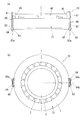
図2及び図3に示すように、シールリング40が転がり軸受21の端面に当接した状態とされ、他の転がり軸受22,23や間座5,6,7等とともにハウジング11内に収容される。
As shown in FIGS. 2 and 3, the
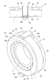
シールリング40は、図4に示すように、その筒軸方向端面41が、外輪1の軸方向一端側の端面1dに当接する円筒状部材からなる円筒部42と、円筒部42の筒軸方向一端部から内径側に向かって立ち上がる壁部43とを備える。
As shown in FIG. 4, the
壁部43には、フィルタ46が設けられている。フィルタ46は、貫通穴からなるフィルタ孔46aの集合によって、転がり軸受21,22の軸受空間からの異物の通過を阻止し、潤滑油の通過は許容されるものである。このとき、フィルタ孔46aの内径は、少量であれば、作動機構部30側へ侵入しても影響がない程度の異物の通過は許容されるよう、適宜の寸法に設定される。
A
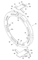
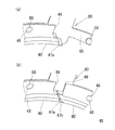
この実施形態では、シールリング40は合成樹脂の成形品からなるものとしている。また、シールリング40は、転がり軸受21の軸受空間の側方開口Dに沿う円環状を成し、その円環の周方向に沿って分割された複数の分割シール部材40’が、連結片80によって円環状に接続された連結体である。周方向に隣り合う分割シール部材40’同士は、連結片80により接続される。連結片80も、合成樹脂の成形品からなるものとしている。
In this embodiment, the
この実施形態では、中心角180°を成す2つの分割シール部材40’で円環状のシールリング40を構成しているので、連結片80は、シールリング40の上部と下部の2箇所に位置している。
In this embodiment, since the
さらに、シールリング40が、中心角180°の分割シール部材40’を二つ用いた2分割構成だけでなく、例えば、中心角90°の分割シール部材40’を四つ用いることで円環状のシールリング40を構成してもよいし、中心角60°の分割シール部材40’を六つ用いることで円環状のシールリング40を構成してもよい。
Furthermore, the
また、この実施形態では、シールリング40は、壁部43のフィルタ46用の孔46aを、シールリング40の本体に一体に形成しているが、壁部43のフィルタ46を、シールリング40の本体の部材とは別部材として、その別部材をシールリング40の本体に、嵌め込み固定、埋め込み固定、接着等の種々の手段で固定するようにしてもよい。
In this embodiment, the
シールリング40や連結片80の素材としては、樹脂以外にも、金属、ゴム等の他の素材を採用してもよい。フィルタ46をシールリング40とは別部材とする場合も、フィルタ46の素材として、樹脂、金属、ゴム等の他の素材を用いることができる。
As a material for the
また、連結片80には、シールリング40の円筒部42の外周面に当接する基部81から、転がり軸受21側へ向かって軸方向へ伸びる軸方向部材82が設けられている。
Further, the connecting
軸方向部材82は、ハウジング11の内径面と外輪1の外径面との間を通って転がり軸受21側へ伸びて、その軸方向部材82が軌道輪や間座等の軸受部材に係合することにより、シールリング40はハウジング11及び外輪1に固定される。
The
この実施形態では、軸方向部材82は、循環経路12内を通って軸方向一端側から他端側へ向かって伸びており、その軸方向部材82の先端82aは先細りの形状となっている。このため、ハウジング11内への挿入がスムーズである。また、軸方向部材82の先端寄りには、内径側へ向かって伸びる内径側突出部83を備えている。
In this embodiment, the
軸方向部材82は外輪1の外径面に接触しつつ、内径側突出部83が軸受の軌道輪や間座に設けた凹部に入り込むことで、シールリング40の軸方向への移動が規制される。この実施形態では、内径側突出部83が、転がり軸受21の外輪1bと間座6との間に形成された凹部1c内に入り込む構成としている。凹部1cは、間座6の一端側端面6aと、転がり軸受21の外輪1bの肩部の稜線部に形成された曲面状のアール部や面取り部等とによって構成されている。
While the
また、循環経路12の軸方向一端側の開口12cは、側面視円環状を成す転がり軸受21の軸受空間の側方開口Dよりも外径側に位置する。この実施形態では、循環経路12の軸方向潤滑経路12aは2本設けられており、周方向に沿って180°の間隔をおいて2箇所に開口12cを有しているが、この開口12cの数は、必要に応じて増減してもよい。
Further, the
連結片80は、循環経路12内側へ突出する外径側突出部84を備える。外径側突出部84は、軸方向部材82の外面から外径側へ向かって立ち上がり、その外径面に凸部84aと凹部84b、及び、通油孔84cを備える。凸部84aは、循環経路12の内面に当接して連結片80を支持し、凹部84bと循環経路12内面との隙間、及び、通油孔84cは、循環経路12から軸受空間外への潤滑油の通路となる。凹部84bと循環経路12の内面との隙間、通油孔84cの内径は、同じく、フィルタ46のメッシュサイズと同じか、そのメッシュサイズ以下に設定される。外径側突出部84に複数の貫通孔やスリットを設けて、異物を捕捉するためのフィルタとすることもできる。
The connecting
また、軸方向部材82及び外径側突出部84は、循環経路12内に入り込んでがたつきなく固定されるよう、その幅(転がり軸受の周方向への幅)は循環経路12の幅(同じく転がり軸受の周方向への幅)と合致している。これにより、シールリング40は、ハウジング11及び外輪1に対して回り止めされる。すなわち、軸方向部材82及び外径側突出部84は、シールリング40の回り止め手段として機能している。
Further, the width (the width in the circumferential direction of the rolling bearing) of the
連結片80には、図5に示すように、基部81から周方向両側へ伸びる対の支え部85が設けられている。支え部85は、シールリング40の外径面に沿う円筒面状の部材である。各支え部85の先端には、内径側へ突出する係止凸部88が設けられている。この係止凸部88が、周方向に隣り合う分割シール部材40’の端部にそれぞれ設けられた係止孔48に入り込むことで、連結片80は、周方向に隣り合う分割シール部材40’の端部同士を接続する。これにより、分割シール部材40’は円環状の連結体に構成される。
As shown in FIG. 5, the connecting
また、分割シール部材40’の端部同士は、図6に示すように、壁部43に設けられ互いに対向するカギ状部47a,47bが噛み合っているので、その接続がより強固となっている。
Further, as shown in FIG. 6, the end portions of the
また、シールリング40の壁部43の内径側端部は、内輪2の大つば外径面にわずかな隙間wを介して対向して、壁部43と内輪2との間に隙間(最後すきま)wを有するラビリンスシール構造を形成している。この隙間wでは、潤滑油は通過が許容されるが、その隙間wの寸法を超える異物の通過は阻止される。壁部43の内径側端部と内輪2の大つば外径面との隙間wは、フィルタ46のメッシュサイズと同じか、そのメッシュサイズ以下に設定される。
Further, the inner diameter side end of the
このように、転がり軸受21,22,23の軸受空間からの潤滑油は、シールリング40に設けたフィルタ46の孔46aや、循環経路12内の孔や隙間、あるいは、壁部43の内径側端部と内輪2の大つば外径面との隙間wを通過して、軸受空間外へ流出する。このため、作動機構部30、70の動作に影響が出るような大きな異物(金属からなる摩耗粉の他、特に剥離片等)は、作動機構部30、70側へは侵入しないようになっている。
As described above, the lubricating oil from the bearing spaces of the rolling
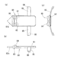
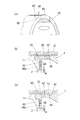
シールリング40の壁部43の内径側端部には、図1(a)及び図4に示すように、内径側へ突出する凸部44が設けられている。この凸部は、内輪2の外径面に摺接するので、凸部44以外の場所において、壁部43の内径側端部は内輪2の外径面に接触しないようになっている。
As shown in FIGS. 1A and 4, a
図4に示すように、凸部44は転がり軸受21の軸受中心を挟んで対称に配置されている。特に、この実施形態では、シールリング40は周方向に沿って分割された複数の分割シール部材40’が連結片80によって接続されて円環状の連結体となっており、凸部44は、その周方向に隣り合う連結片間の中間地点に備えている。このため、シールリング40は周方向に沿って2箇所に凸部44が設けられている。
As shown in FIG. 4, the
ただし、この凸部44の設置数は自由に増減できる。凸部44を、周方向に隣り合う連結片80間を等分方位に分割する地点、例えば、中心角180°の分割シール部材40’に対し、周方向に隣り合う連結片80間の3等分方位の地点に60°の角度を隔てて合計2箇所の凸部44、あるいは、周方向に隣り合う連結片80間の4等分方位の地点に45°の角度を隔てて合計3箇所の凸部44を設けてもよい。ただし、凸部44は、シールリング40の全周を通じて少なくとも2箇所、特に、転がり軸受21の軸受中心を挟んで対称に配置されていることが望ましい。
However, the number of the
凸部44を設けたことにより、シールリング40は、凸部44のみが内輪2に摺接して摩耗するが、他の部分は摩耗しないようになる。このため、シールリング40を構成する部材に製造時における公差内の寸法誤差が含まれていても、シールリング40の壁部43の内径側端部と内輪2の外径面との間の最後すきまwは、その凸部44の突出高さw1を下回ることはない。このため、凸部44以外の部分が内輪2に摺接して摩耗することを防止できる。凸部44以外の部分が摩耗しなければ、最後すきまの拡大を回避することができる。また、凸部44が摩耗した際に、その残存する凸部44の突出高さw1を計測すれば、最後すきまの寸法管理が容易である。
By providing the
また、シールリング40が熱膨張した際にも、凸部44が内輪2の外径面に摺接することで、シールリング40の壁部43の内径側端部と内輪2の外径面との間の最後すきまwは、その凸部44の突出高さw1を下回ることがない。このため、シールリング40の熱膨張の際にも、凸部44以外の部分が内輪2に摺接して摩耗することを防止できる。
Further, when the
また、この実施形態のシールリング40は合成樹脂製であり、特に、内部にグラスファイバを含有する繊維強化樹脂製である。このため、シールリング40を成型する際に、型枠内に未硬化の繊維強化樹脂を充填すると、グラスファイバは、微小な凸部44内には入り込まない。このため、樹脂の硬化によって完成したシールリング40は、凸部44内にはグラスファイバを介在せず、樹脂のみで成型されたものとなる。このため、凸部44が摩耗した際に、グラスファイバの摩耗粉が潤滑油内に入り込むことも防止できる。
Further, the
凸部44の大きさは、グラスファイバを含有する繊維強化樹脂を型枠内に充填する際、凸部44に対応する型枠内の凹部にグラスファイバが入り込みにくい程度の微小な突出量とすることが望ましい。この実施形態では、最後すきまwは、フィルタ46のメッシュサイズと同じ0.3mmに設定されているので、この凸部44の突出高さw1も0.3mmに設定される。なお、図4に示す、転がり軸受21の軸方向への凸部44の幅w2、転がり軸受の周方向への凸部44の幅w3は、求められる耐摩耗性能に基づいて自由に設定できる。
The size of the
凸部44の形状は、この実施形態では、転がり軸受の周方向に沿ってその中央で最も高く、そこから周方向両側へ向かうにつれて円弧状に低くなる半円状としているが、この凸部44の形状を、例えば、転がり軸受の周方向に沿ってその中央で最も高く、そこから周方向両側へ向かうにつれて直線的に低くなる三角形状とすることもできる。
In this embodiment, the shape of the
また、この実施形態では、凸部44を含むシールシング40の素材を繊維合成樹脂製としているが、内輪2の外径面に当接する凸部44を、耐摩耗性能の高い別の素材としてもよい。例えば、耐摩耗性能の高い合成樹脂や、金属等を採用してもよい。凸部44をシールリング40の本体とは別の素材とする場合、シールリング40の本体とは別部材とした凸部44を含む部材を、嵌め込み固定、接着、溶着等の種々の手法で一体化することができる。
Further, in this embodiment, the material of the seal singing 40 including the
また、図7(a)(b)に示すように、シールリング40の円筒部42に、外輪1の内径面に係合してシールリング40の半径方向への移動を拘束する外輪係止凸部45を備えている。外輪係止凸部45は、外輪1の端面1dと内径面との間の稜線部から、外輪1の軌道面1aへと続く内径面にかけて係合して、シールリング40を拘束している。
Further, as shown in FIGS. 7A and 7B, an outer ring locking protrusion that engages with the inner diameter surface of the
このため、シールリング40が熱膨張した際に、外輪係止凸部45の外輪1の内径面への係合により、シールリング40が外径側へ動くことが規制されるので、壁部43の内径側端部と内輪2の外径面との間の最後すきまwが拡大することを防止できる。
For this reason, when the
この実施形態では、外輪係止凸部45をシールリング40とは別の線膨張係数の低い素材としている。ここでは、外輪係止凸部45を備える着脱部材50を、シールリング40の本体とは別部材として、その部材を、嵌め込み固定、接着、溶着等の種々の手法で一体化している。着脱部材50の素材は、線膨張係数の低い合成樹脂や、金属等を採用してもよい。また、外輪係止凸部45を、シールリング40と一体に形成してもよい。
In this embodiment, the outer
また、図7(c)に示すように、シールリング40の円筒部42に、ハウジング11の内径面に当接してシールリング40の半径方向への移動を拘束するハウジング当接部51を備えている。前述のように、図1の例では、連結片80はハウジンク11の内面に係止されているが、シールリング40の本体である円筒部42は、ハウジング11には直接拘束されていなかった。このため、図7(c)に示すように、シールリング40の円筒部42に、ハウジング11の内径面に当接してシールリング40の半径方向への移動を拘束するハウジング当接部51を設けたものである。
Further, as shown in FIG. 7C, the
シールリング40が熱膨張した際に、ハウジング当接部51がハウジング11の内径面へ当接して、シールリング40が外径側へ動くことが規制されるので、壁部43の内径側端部と内輪2の外径面との間の最後すきまwが拡大することを防止できる。
When the
上記の各実施形態において、シールリング40に設けられるフィルタ46の孔46a周辺に、金属粉等の異物の付着を検出するセンサ部を備えてもよい。センサ部としては、例えば、対の電極間に異物が介在することにより、その異物が電極間を短絡した際の電気的出力の変化によって、異物の存在を検知する電気式センサを採用することができる。
In each of the embodiments described above, a sensor unit that detects adhesion of a foreign substance such as metal powder may be provided around the
例えば、対の電極間に、フィルタ46の孔46aを通過できない大きさの金属からなる異物が付着することに伴って、その対の電極からケーブルを通じて接続された出力検出装置は、対の電極間の異物を介した導通によって、電気回路の電気的出力の変化を検出し、潤滑油に含まれる金属からなる異物の状態(含有量)を検知することができる。対の電極に接続されたケーブルは、基板を経由してハウジング11外に引き出されて、そのケーブルに接続された出力検出装置がいずれかの部分に設けられる。シールリング40外にケーブルを引き出すためのセンサ孔は、シールリング40の円筒部42や壁部43等に設けることができる。
For example, when a foreign object made of metal of a size that cannot pass through the
また、上記の実施形態では、シールリング40にフィルタ46を設けたが、フィルタ46を備えないシールリング40においても、この発明の内容を適用できる。また、分割シール部材40’や連結片80を用いた分割型のシールリング40以外にも、分割型ではない一体型の円環状のシールリング40においても、この発明の内容を適用できる。
In the above embodiment, the
この発明のシール部材は、実施形態以外の各種の転がり軸受ユニットにも適用できる。さらに、そのシール部材を備えた転がり軸受ユニットは、オイルポンプ60以外の各種装置にも適用できる。特に、この発明の転がり軸受は、転がり軸受から発生する摩耗粉(鉄粉等)等の異物が、潤滑油の循環経路の途中にある作動機構部70に侵入することを防ぐ必要がある種々の装置に適用できる。
The seal member of the present invention can be applied to various rolling bearing units other than the embodiment. Further, the rolling bearing unit including the seal member can be applied to various devices other than the
1 外輪(外側軌道輪)
2 内輪(内側軌道輪)
3 転動体
4 保持器
5,6,7 間座
8 押え部材
10 オイルポンプ装置
11 ハウジング
12,13 循環経路
20 軸受ユニット
21,22,23 転がり軸受
30 作動機構部
31 接続部材
32 軸部材
40 シールリング(シール部材)
40’ 分割シール部材
44 凸部
45 外輪係止凸部
46 フィルタ
50 着脱部材
51 ハウジング当接部
60 オイルポンプ
70 作動機構部
80 連結片
81 基部
82 軸方向部材
83 内径側突出部
84 外径側突出部
85 支え部
1 Outer ring (outer raceway)
2 Inner ring (inner race)
DESCRIPTION OF
40 '
Claims (6)
前記外輪と前記内輪との間の軸受空間に配置される転動体と、
前記外輪又は前記外輪に固定された部材に取り付けられて前記軸受空間の側方開口を覆う円環状のシール部材と、
前記シール部材の内径側端部に設けられ前記内輪の外径面に摺接する凸部と、
を備える転がり軸受ユニット。 An outer ring and an inner ring,
A rolling element disposed in a bearing space between the outer ring and the inner ring;
An annular seal member attached to the outer ring or a member fixed to the outer ring and covering a side opening of the bearing space;
A convex portion provided at an inner diameter side end of the seal member and in sliding contact with the outer diameter surface of the inner ring;
A rolling bearing unit comprising:
請求項1に記載の転がり軸受ユニット。 The rolling bearing unit according to claim 1, wherein the convex portions are arranged symmetrically with respect to the bearing center.
前記凸部を、周方向に隣り合う前記連結片間を等分方位に分割する地点に備える
請求項1又は2に記載の転がり軸受ユニット。 The sealing member is an annular coupling body in which a plurality of divided sealing members divided along the circumferential direction are connected by a coupling piece,
The rolling bearing unit according to claim 1, wherein the convex portion is provided at a point where the connecting pieces adjacent in the circumferential direction are divided into equal parts.
請求項1〜3のいずれか一つに記載の転がり軸受ユニット。 The rolling bearing unit according to claim 1, wherein the seal member is made of a fiber reinforced resin.
前記円筒部に前記外輪の内径面に係合してシールリングの半径方向への移動を拘束する外輪係止凸部を備える
請求項1〜4のいずれか一つに記載の転がり軸受ユニット。 The seal member includes a cylindrical portion that comes into contact with an end surface of the outer ring, and a wall portion that rises from the one end portion in the cylinder axis direction of the cylindrical portion toward the inner diameter side,
The rolling bearing unit according to any one of claims 1 to 4, wherein the cylindrical portion includes an outer ring locking convex portion that engages with an inner diameter surface of the outer ring and restricts movement of the seal ring in a radial direction.
前記シール部材は、前記外輪の端面に当接する円筒部と、前記円筒部の筒軸方向一端部から内径側に向かって立ち上がる壁部とを備え、
前記円筒部に前記ハウジングの内径面に当接してシールリングの半径方向への移動を拘束するハウジング当接部を備える
請求項1〜5のいずれか一つに記載の転がり軸受ユニット。 The outer ring is fixed in the housing;
The seal member includes a cylindrical portion that comes into contact with an end surface of the outer ring, and a wall portion that rises from the one end portion in the cylinder axis direction of the cylindrical portion toward the inner diameter side,
The rolling bearing unit according to any one of claims 1 to 5, further comprising a housing contact portion that contacts the inner diameter surface of the housing and restrains the radial movement of the seal ring on the cylindrical portion.
Priority Applications (4)
| Application Number | Priority Date | Filing Date | Title |
|---|---|---|---|
| JP2016079632A JP2017190811A (en) | 2016-04-12 | 2016-04-12 | Rolling bearing unit |
| US16/092,984 US11105374B2 (en) | 2016-04-12 | 2017-04-05 | Rolling bearing unit |
| CN201780023040.XA CN108884875B (en) | 2016-04-12 | 2017-04-05 | Rolling bearing unit |
| PCT/JP2017/014256 WO2017179470A1 (en) | 2016-04-12 | 2017-04-05 | Rolling bearing unit |
Applications Claiming Priority (1)
| Application Number | Priority Date | Filing Date | Title |
|---|---|---|---|
| JP2016079632A JP2017190811A (en) | 2016-04-12 | 2016-04-12 | Rolling bearing unit |
Publications (1)
| Publication Number | Publication Date |
|---|---|
| JP2017190811A true JP2017190811A (en) | 2017-10-19 |
Family
ID=60084602
Family Applications (1)
| Application Number | Title | Priority Date | Filing Date |
|---|---|---|---|
| JP2016079632A Pending JP2017190811A (en) | 2016-04-12 | 2016-04-12 | Rolling bearing unit |
Country Status (1)
| Country | Link |
|---|---|
| JP (1) | JP2017190811A (en) |
Cited By (1)
| Publication number | Priority date | Publication date | Assignee | Title |
|---|---|---|---|---|
| US20190178292A1 (en) * | 2016-07-15 | 2019-06-13 | Ihi Corporation | Seal structure and turbocharger |
-
2016
- 2016-04-12 JP JP2016079632A patent/JP2017190811A/en active Pending
Cited By (2)
| Publication number | Priority date | Publication date | Assignee | Title |
|---|---|---|---|---|
| US20190178292A1 (en) * | 2016-07-15 | 2019-06-13 | Ihi Corporation | Seal structure and turbocharger |
| US10648511B2 (en) * | 2016-07-15 | 2020-05-12 | Ihi Corporation | Seal structure and turbocharger |
Similar Documents
| Publication | Publication Date | Title |
|---|---|---|
| CN109356938B (en) | Sealing device | |
| CN104884830B (en) | Rolling bearing | |
| JP6629550B2 (en) | Rotary joint | |
| WO2008005299A2 (en) | Bearing assembly and resilient seal element | |
| WO2017179470A1 (en) | Rolling bearing unit | |
| JP2014231856A (en) | Rolling bearing | |
| JP5598075B2 (en) | Rolling bearing device | |
| JP6852260B2 (en) | Roller bearing | |
| JP2016084911A (en) | Bearing device for wheel | |
| JP2017190813A (en) | Rolling bearing unit | |
| US9353795B2 (en) | Rolling bearing | |
| US10094424B2 (en) | Rolling bearing | |
| CN106499734B (en) | Sealing device for roller bearing unit | |
| WO2017164005A1 (en) | Double row bearing | |
| JP2017190866A (en) | Rolling bearing unit | |
| JP2017190811A (en) | Rolling bearing unit | |
| JP2017180727A (en) | Rolling bearing unit | |
| JP2017223351A (en) | Rolling bearing unit | |
| JP6635861B2 (en) | Rolling bearing unit | |
| JP2018168994A (en) | Rolling bearing unit | |
| WO2017179617A1 (en) | Rolling bearing unit | |
| JP2017089797A (en) | Rolling bearing | |
| JP6616163B2 (en) | Rolling bearing | |
| JP2006064147A (en) | Bearing having rotation sensor | |
| IT202300002274A1 (en) | BEARING UNIT |
Legal Events
| Date | Code | Title | Description |
|---|---|---|---|
| A621 | Written request for application examination |
Free format text: JAPANESE INTERMEDIATE CODE: A621 Effective date: 20190327 |
|
| A131 | Notification of reasons for refusal |
Free format text: JAPANESE INTERMEDIATE CODE: A131 Effective date: 20200107 |
|
| A521 | Written amendment |
Free format text: JAPANESE INTERMEDIATE CODE: A523 Effective date: 20200303 |
|
| A131 | Notification of reasons for refusal |
Free format text: JAPANESE INTERMEDIATE CODE: A131 Effective date: 20200407 |
|
| A02 | Decision of refusal |
Free format text: JAPANESE INTERMEDIATE CODE: A02 Effective date: 20201110 |