JP6639768B2 - Sheet processing apparatus and image forming system using the same - Google Patents
Sheet processing apparatus and image forming system using the same Download PDFInfo
- Publication number
- JP6639768B2 JP6639768B2 JP2013260097A JP2013260097A JP6639768B2 JP 6639768 B2 JP6639768 B2 JP 6639768B2 JP 2013260097 A JP2013260097 A JP 2013260097A JP 2013260097 A JP2013260097 A JP 2013260097A JP 6639768 B2 JP6639768 B2 JP 6639768B2
- Authority
- JP
- Japan
- Prior art keywords
- sheet
- unit
- binding
- processing
- punch
- Prior art date
- Legal status (The legal status is an assumption and is not a legal conclusion. Google has not performed a legal analysis and makes no representation as to the accuracy of the status listed.)
- Active
Links
- 238000012545 processing Methods 0.000 title claims description 184
- 238000000034 method Methods 0.000 claims description 31
- 238000004080 punching Methods 0.000 claims description 30
- 230000008569 process Effects 0.000 claims description 25
- 230000001105 regulatory effect Effects 0.000 claims description 22
- 238000011068 loading method Methods 0.000 claims description 12
- 238000001514 detection method Methods 0.000 claims description 7
- 230000007246 mechanism Effects 0.000 description 67
- 238000012805 post-processing Methods 0.000 description 29
- 230000033001 locomotion Effects 0.000 description 17
- 238000010586 diagram Methods 0.000 description 14
- 230000003028 elevating effect Effects 0.000 description 14
- 238000003825 pressing Methods 0.000 description 13
- 238000007599 discharging Methods 0.000 description 10
- 238000007639 printing Methods 0.000 description 9
- 238000012546 transfer Methods 0.000 description 9
- 230000032258 transport Effects 0.000 description 9
- 238000011144 upstream manufacturing Methods 0.000 description 8
- 230000008275 binding mechanism Effects 0.000 description 6
- 230000005540 biological transmission Effects 0.000 description 5
- 238000005096 rolling process Methods 0.000 description 5
- 238000003860 storage Methods 0.000 description 5
- 238000001125 extrusion Methods 0.000 description 4
- 230000009467 reduction Effects 0.000 description 4
- 230000015572 biosynthetic process Effects 0.000 description 3
- 238000006243 chemical reaction Methods 0.000 description 3
- 230000001276 controlling effect Effects 0.000 description 3
- 238000009434 installation Methods 0.000 description 3
- 230000003287 optical effect Effects 0.000 description 3
- 239000002699 waste material Substances 0.000 description 3
- 238000013459 approach Methods 0.000 description 2
- 238000013461 design Methods 0.000 description 2
- 238000005553 drilling Methods 0.000 description 2
- 239000002184 metal Substances 0.000 description 2
- 239000011347 resin Substances 0.000 description 2
- 229920005989 resin Polymers 0.000 description 2
- 230000007723 transport mechanism Effects 0.000 description 2
- 101150073618 ST13 gene Proteins 0.000 description 1
- 101150001619 St18 gene Proteins 0.000 description 1
- 230000005856 abnormality Effects 0.000 description 1
- 238000005452 bending Methods 0.000 description 1
- 239000011248 coating agent Substances 0.000 description 1
- 238000000576 coating method Methods 0.000 description 1
- 239000000428 dust Substances 0.000 description 1
- 238000007667 floating Methods 0.000 description 1
- 230000006872 improvement Effects 0.000 description 1
- 238000007641 inkjet printing Methods 0.000 description 1
- 238000002955 isolation Methods 0.000 description 1
- 238000007645 offset printing Methods 0.000 description 1
- 239000010893 paper waste Substances 0.000 description 1
- 230000000149 penetrating effect Effects 0.000 description 1
- 108091008695 photoreceptors Proteins 0.000 description 1
- 238000004886 process control Methods 0.000 description 1
- 238000011112 process operation Methods 0.000 description 1
- 230000003014 reinforcing effect Effects 0.000 description 1
- 230000004044 response Effects 0.000 description 1
- 238000000926 separation method Methods 0.000 description 1
- 238000000859 sublimation Methods 0.000 description 1
- 230000008022 sublimation Effects 0.000 description 1
- 238000010023 transfer printing Methods 0.000 description 1
- 235000013311 vegetables Nutrition 0.000 description 1
Images


Description
本発明は、画像形成されたシートを処理するシート処理装置に係わり、パンチ機構の改良に関する。 The present invention relates to a sheet processing apparatus for processing a sheet with an image formed, an improvement of a punch mechanism.
一般にこの種のシート処理装置は、画像形成装置の排紙口に連結され画像形成されたシートを一時的に保持して処理した後にスタックトレイに収納する装置として知られ、処理機構として集積したシート束を綴じ処理にする綴じ機構、パンチ穴を穿孔するパンチ機構、折り処理する折り処理機構、捺印処理する捺印機構等が知られている。 Generally, this kind of sheet processing apparatus is known as an apparatus for storing a stack tray after processing the sheet connected to the image formed on the sheet discharge outlet of the image forming apparatus is temporarily held, processing mechanism There are known a binding mechanism for binding a bundle of sheets, a punch mechanism for punching punch holes, a folding mechanism for folding, and a stamping mechanism for stamping.
例えば特許文献1には、画像形成装置の排紙口に連結され画像形成されたシートを搬入経路から処理トレイに案内して束状に集積し綴じ処理したのちに下流側のスタックトレイに収納する装置が開示されている。同文献には、搬入経路にシートにパンチ穴を穿孔するパンチユニットを配置し、搬入口に送られたシートを一時的に停止して穿孔処理した後に排紙口から処理理トレイあるいはスタックトレイに案内するパンチ機構が提案されている。 For example, in Japanese Patent Application Laid-Open No. H11-158, a sheet on which an image is formed by being connected to a discharge port of an image forming apparatus is guided from a carry-in path to a processing tray, collected in a bundle, bound, and then stored in a stack tray on the downstream side. An apparatus is disclosed. According to the document, a punch unit that punches a punch hole in a sheet is arranged in a carry-in path, a sheet sent to a carry-in port is temporarily stopped, and a punching process is performed. A guiding punch mechanism has been proposed.
また、シート処理装置において上流側から搬入されるシートに処理(綴じ処理)を施すのと同時に、外装ケーシングにマニュアルセット部を設けてオペレータがセットしたシート束を綴じ処理するマニュアル綴じ機構を装備した装置が例えば特許文献2に提案されている。 Further, sheet processing apparatus sheet processing (binding processing) which is carried from the upstream side in the same time as the applied manual binding mechanism for binding processing of the sheet bundle the operator has set the manual setting unit provided in the outer casing An apparatus equipped with is proposed in, for example, Patent Document 2.
上述のように、画像形成装置などで画像形成されたシートを綴じ処理部に案内して綴じ処理にした後にスタックトレイに収納する処理装置は既に知られている。そしてこのような装置でシート搬入経路にパンチユニットを配置し、綴じ処理部に案内するシートにパンチ穴を穿孔するユニットも前述の特許文献1などで知られている。また、外装ケーシングにシート束を挿入するマニュアルセット部を設けてセットしたシート束を綴じ処理する機構も特許文献2などで知られている。
As mentioned above, processing device you stored on the stack tray after the binding process to guide the processing unit binding the sheet on which an image is formed by an image forming apparatus are already known. A unit for arranging a punch unit in a sheet carrying-in path by such an apparatus and punching a punch hole in a sheet to be guided to a binding processing unit is also known from
本発明は、シートにパンチ穴を穿孔する処理と、セット部でシート束を綴じ処理する処理が可能なシート処理装置をコンパクトに構成することを課題としている。 The present invention has a task and processing for perforating punch holes in the sheet over preparative, to constitute a sheet processing apparatus capable processing is that processes stapled sheet bundle to the compact in degrees Tsu isolation portion.
上記課題を解決するため、本発明に係るシート処理装置は、シートを搬送するための搬送経路と、前記搬送経路においてシートが搬送される搬送方向と直交するシート幅方向において一方側に側枠フレームを有する、装置フレームと、前記シート幅方向において前記側枠フレームの前記一方側に配置されるカバーに形成される開口と、前記側枠フレームの前記一方側に配置され、前記シート処理装置の外部から前記開口を介して挿入されたシート束の下面を支持するセット面と、前記側枠フレームの前記一方側に配置され、前記開口を介して挿入された該シート束の端部が突き当たることによって該シートの位置を規制する規制面と、を有するセット部と、前記セット部とは異なる位置に配置され、前記搬送経路から搬送されたシートを積載する積載手段と、前記セット部にセットされたシート束を綴じることが可能であるとともに、前記積載手段に積載されたシート束を綴じることが可能な綴じ手段と、前記搬送経路に配置されるとともに、前記シート幅方向に位置移動可能に前記装置フレームに取り付けられ、シートを穿孔するパンチ部材を有するパンチユニットと、を有し、前記パンチユニットが前記シート幅方向において前記一方側に最も移動した状態において、前記シート幅方向における前記パンチユニットの前記一方側の端部は、前記シート幅方向において、前記側枠フレームよりも、前記一方側に位置しており、前記搬送経路においてシートが搬送される前記搬送方向と直交する前記シート幅方向において、前記セット部は、前記セット部においてシート束がセットされる領域であるシートセット領域が前記パンチユニットの前記端部の移動領域と重なり合うように配置されている、ことを特徴とする。 To solve the above problem, a sheet processing apparatus according to the present invention, a transport path for transporting the sheet over bets, side to one side in the sheet width direction orthogonal to the conveying direction of the sheet is transported in the transport path An apparatus frame having a frame, an opening formed in a cover disposed on the one side of the side frame in the sheet width direction, and the sheet processing apparatus disposed on the one side of the side frame; A set surface for supporting the lower surface of the sheet bundle inserted from the outside through the opening, and an end of the sheet bundle inserted through the opening disposed on the one side of the side frame and abutting against the set surface. loading a set portion having a restricting surface for restricting the position of the seat, are arranged in a position different from the setting section, the sheet conveyed from the conveying path by That the stacking means, together it is possible to bind the set sheet bundle to the set portion, a binding means capable of binding the sheet bundle stacked on the stacking means, is disposed on the transport path Rutotomoni A punch unit having a punch member for punching a sheet, the punch unit being attached to the apparatus frame so as to be movable in the sheet width direction , wherein the punch unit is most moved to the one side in the sheet width direction. , The one end of the punch unit in the sheet width direction is located on the one side relative to the side frame in the sheet width direction, and the sheet is conveyed in the conveyance path. in the sheet width direction orthogonal to the conveying direction, the mounting portion, the sheet bundle is set in the mounting portion Sheet set region is a region is disposed so as to overlap with the moving region of the end of the punch unit, characterized in that.
本発明は装置をコンパクトに構成することができる。 The present invention allows the apparatus to be compact .
[画像形成装置]
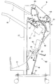
図1に示す画像形成システムにおける画像形成装置Aを説明する。図示の画像形成装置Aは静電式印刷機構を示し、画像形成ユニットA1とスキャナユニットA2とフィーダユニットA3で構成されている。装置ハウジング1には設置面(例えば床面)に設置する据付脚25が設けられている。また装置ハウジング内部には、給紙部2と画像形成部3と排紙部4とデータ処理部5が内蔵されている。
[Image forming apparatus]
The image forming apparatus A in the image forming system shown in FIG. 1 will be described. The illustrated image forming apparatus A shows an electrostatic printing mechanism, and includes an image forming unit A1, a scanner unit A2, and a feeder unit A3. The
給紙部2は、画像形成する複数サイズのシートを収納するカセット機構2a〜2cで構成され、本体制御部90から指定されたサイズのシートを給紙経路6に繰り出す。このため装置ハウジング1には複数のカセット2a〜2cが着脱可能に配置され、各カセットには内部のシートを1枚ずつ分離する分離機構と、シートを繰り出す給紙機構が内蔵されている。給紙経路6には、複数のカセット2a〜2cから供給されるシートを下流側に給送する搬送ローラ7と、経路端部には各シートを先端揃えするレジストローラ対8が設けられている。
The paper feeding unit 2 includes
尚上述の給紙経路6には、大容量カセット2dと手差しトレイ2eが連結してあり、大容量カセット2dは大量に消費するサイズのシートを収納するオプションユニットで構成され、手差しトレイ2eは、分離給送が困難な厚紙シート、コーティングシート、フィルムシートなどの特殊シートを供給可能に構成する。
Note that the large-
画像形成部3は、静電印刷機構を一例として示し、感光体9(ドラム、ベルト)と、この感光体に光学ビームを発光する発光器10と、現像器11(ディベロッパー)と、クリーナ(不図示)が回転する感光体の周囲に配置されている。図示のものはモノクロ印刷機構を示し、感光ドラム9に発光器で光学的に潜像を形成し、この潜像に現像器11でトナーインクを付着する。
The
そして感光体9に画像形成するタイミングに合わせて給紙経路6からシートを画像形成部3に送り転写チャージャ12でシート上に画像を転写し、排紙経路14に配置されている定着ユニット(ローラ)13で定着する。排紙経路14には排紙ローラ15と、排紙口16が配置され、後述するシート後処理装置Bにシートを搬送する。
Then, the sheet is fed from the
上述のスキャナユニットA2は、画像原稿を載置するプラテン17と、プラテンに沿って往復動するキャリッジ18と、キャリッジに搭載された光源と、プラテン上の原稿からの反射光を光電変換手段19に案内する縮小光学系20(ミラー、レンズの組み合わせ)で構成されている。図示21は第2プラテン(走行プラテン)であり、フィーダユニットA3から送られたシートを上述のキャリッジ18と縮小光学系20で画像読み取りする。光電変換手段19は光電変換したが画像データを電気的に画像形成部3に転送する。
The above-described scanner unit A2 includes a
フィーダユニットA3は給紙トレイ22と、給紙トレイから送り出したシートを走行プラテン21に案内する給紙経路23と、プラテンで画像読取された原稿を収納する排紙トレイ24で構成されている。
The feeder unit A3 is composed of a
画像形成装置Aは、上述の機構に限らず、オフセット印刷機構、インクジェット印刷機構、インクリボン転写印刷機構(熱転写リボン印刷、昇華型リボン印刷など)の印刷機構が採用可能である。 The image forming apparatus A is not limited to the above-described mechanism, and may employ a printing mechanism such as an offset printing mechanism, an inkjet printing mechanism, and an ink ribbon transfer printing mechanism (thermal transfer ribbon printing, sublimation type ribbon printing, etc.).
[シート後処理装置]
シート後処理装置Bは、画像形成装置Aの排紙口16から搬出されたシートを後処理する装置として、(1)画像形成されたシートを積載収容する機能(第1、第3処理部B1,B3;プリントアウトモード)と、(2)画像形成されたシートを部分け収納する機能(第3処理部B3;ジョグ仕分モード)と、(3)画像形成されたシートを部揃え集積して綴じ処理する機能(第1処理部B1;綴じ処理モード)と、(4)画像形成されたシートを部揃えして綴じ処理した後に折り処理して製本仕上げする機能(第2処理部B2;製本処理モード)とを備える。
[Sheet post-processing device]
The sheet post-processing device B is a device that post-processes a sheet conveyed from the
なお、本発明にあってシート後処理装置Bは上述の全ての機能を備える必要はなく、装置仕様(設計仕様)に応じて適宜構成すると良い。この場合にもシートを部揃え集積する処理部(第1処理部B1)と、この処理部に第1、第2の綴じ手段(後述する針綴じユニット47と針なし綴じユニット51)を備え、選択された綴じ手段で綴じ処理した後に収納するスタック構成は必要としている。
In the present invention, the sheet post-processing apparatus B does not need to have all the above-described functions, and may be appropriately configured according to the apparatus specifications (design specifications). Also in this case, a processing section (first processing section B1) for aligning and stacking sheets, and first and second binding means (a
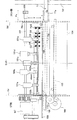
図2には、シート後処理装置Bの詳細構成を示す。シート後処理装置Bは画像形成装置Aの排紙口16に連なる搬入口26と、この搬入口から搬入したシートを後処理した後に収納部(後述の第1スタックトレイ49、第2スタックトレイ61、第3スタックトレイ71)に収納する。
FIG. 2 shows a detailed configuration of the sheet post-processing apparatus B. The sheet post-processing apparatus B includes a carry-in
図示の装置はシート搬入経路28に送られたシートを、第1処理部B1から第1スタックトレイ49(以下「第1トレイ」と云う)に、第2処理部B2から第2スタックトレイ61(以下「第2トレイ」と云う)に、第3処理部B3から第3スタックトレイ71(以下「第3トレイ」と云う)に移送する。
The illustrated apparatus transfers the sheet sent to the sheet carry-in
第1処理部B1は、シート搬入経路28の経路出口(排紙口)35に配置され、順次送られたシートを部揃え集積して綴じ処理したのちに第1トレイ(第1収納部;以下同様)49に収納する。第2処理部B2は、シート搬入経路28から分岐した経路出口62(後述の第2スイッチバックパス端)に配置され、順次送られるシートを部揃え集積して綴じ処理した後に折り処理して第2トレイ(第2収納部;以下同様)61に収納する。第3処理部B3は、シート搬入経路28に組み込まれ、搬送するシートを搬送方向(シート搬入経路28に搬送されるシートの搬送方向)と交差する方向(本実施形態においては直交する方向)に所定量オフセットさせて区分けした後に第3トレイ(第3収納部;以下同様)71に収納する。以下、各構成について詳述する。
The first processing unit B1 is disposed at a path exit (sheet discharge port) 35 of the sheet carry-in
「装置ハウジング」
図2に示すように、シート後処理装置Bは装置ハウジング27と、この装置ハウジング内部に内蔵され、搬入口26と排紙口35を有するシート搬入経路28と、この経路から送られたシートを後処理する第1処理部B1と第2処理部B2と、第3処理部B3と、各処理部から送られたシートを収納する第1、第2、第3トレイ49,61,71を備えている。図示の装置ハウジング27は上流側に位置する画像形成装置Aのハウジング1と略同一高さ寸法に配置され、設置面から画像形成装置Aの排紙口16とシート後処理装置Bの搬入口26が連結される。
"Equipment housing"
As shown in FIG. 2, the sheet post-processing apparatus B includes an
図2に示す装置のハウジング27は装置フレーム70と、外装カバー73で構成されている。装置フレーム70は、図示のようなボックス型の装置の骨組みを形成し、図1の状態で正面に位置するフロント側の側枠フレーム70fと、背面に位置するリヤ側の側枠フレーム70rと、両側枠フレーム間を連結するステー部材70s(連結補強部材)で構成されている。この左右の側枠フレーム間に、後述するシート搬入経路28、処理トレイ37、スタックトレイ49などが取り付けられる。
The
外装カバー73は、フロント側の側枠フレーム70fを覆うフロントカバー73fと、リヤ側の側枠フレームを覆うリアカバー73rで構成されている。装置ハウジング27は、図示の形状に制限されることなくデザイン上好適な形態とすることは勿論、装置フレーム70も左右側枠と連結ステー構造に限らず、モノコック構造など種々のフレーム構造が採用可能である。
The exterior cover 73 includes a
「シート搬入経路」
シート搬入経路28は、装置ハウジング27を略水平方向に横断する直線経路で構成され、画像形成装置Aの排紙口(本体排紙口)16と連なる搬入口26と、この搬入口から装置を横断して反対側に位置する排紙口35を備えている。このシート搬入経路28には、搬入口26から排紙口35に向けてシートを搬送する搬送ローラ29(ローラ、ベルトなどのシート搬送手段)と、排紙口35に配置された排紙ローラ36(ベルトであっても良い)と、経路に搬入するシートの先後端を検出する入口センサS1と、経路排紙口でシートの先後端を検出する排紙センサS2が配置されている。
"Sheet loading path"
The sheet carry-in
上述のシート搬入経路28は搬入口26からシートを第1処理部B1と第2処理部B2に振り分けて移送するように連結され、経路排紙方向の上流側に第2処理部B2が、下流側に第1処理部B1が連結されている。略直線形状のシート搬入経路28は、搬入口26からのシートを、第2処理部B2に向けて移送するように経路分岐され、次いで経路排紙口35の下流側に配置されている第1処理部B1に案内する経路構成となっている。
The above-described sheet carry-in
また上述のシート搬入経路28には、第1、第2処理部B1、B2で後処理を施さないシートを第3トレイ71に案内する第3排紙パス(プリントアウト排紙パス)30が連結され、第3トレイ(オーバフロートレイ)71にシートを案内するように構成されている。このシート搬入経路28には第3処理部B3が内蔵され、この処理部は経路を搬送するシートを排紙直交方向にオフセットさせて区分けするジョグ仕分けする。つまりシート搬入経路28には第3処理部B3が内蔵され、この処理部でジョグ仕分けされたシートは第3トレイ71に収納される。
Further, a third discharge path (printout discharge path) 30 for guiding a sheet not subjected to post-processing in the first and second processing units B1 and B2 to the
上記シート搬入経路28には、図2に示すように搬入口26から下流側に、「第3排紙パス30」「第2排紙パス32」「第1排紙パス31」の順に配置され、図示位置に第1経路切換え手段33と第2経路切換手段34が配置されている。また、第2排紙パス32と第1排紙パス31は、シート搬送方向を反転して各処理部に案内するスイッチバックパスで構成されている。
In the sheet carry-in
上記第3排紙パス30は搬入口26から送られたシートを第3トレイに案内し、第2排紙パス32は搬入口26から送られたシートを第2トレイ61に案内し、第1排紙パス31は搬入口26かられたシートを第1トレイ49に案内する。そして第3トレイ71に案内されるシートは経路中の第3処理部B3でジョグ仕分け処理され、第2トレイ61に案内されるシートは第2処理部B2で製本処理され、第1トレイ49に案内されるシートは、第1処理部B1で綴じ処理が施される。
The third
上記第1経路切換え手段33は、シート搬送方向を変更するフラッパガイドで構成され、図示しない駆動手段(電磁ソレノイド、ミニモータなど)に連結されている。この切換え手段33で搬入口26からのシートを第3排紙パス30に案内するか、第1、第2排紙パス31、32に案内するのかを選定する。上記第2経路切換え手段34は、搬入口26から送られたシートを第2処理部B2に案内するか、その下流側の第1処理部B1に案内するか選定する。第2経路切換え手段34にも図示しない駆動手段が連結されている。またシート搬入経路28には、搬入されたシートにパンチ穴を穿孔するパンチユニット100が配置されている。
The first path switching means 33 is composed of a flapper guide for changing the sheet conveyance direction, and is connected to a driving means (an electromagnetic solenoid, a mini motor, or the like) not shown. The switching
[第1処理部]
第1処理部B1は、シート搬入経路28の下流側に配置され排紙口35から送られたシートを部揃え集積する処理トレイ37と、集積されたシート束を綴じ処理する綴じ処理機構で構成される。図2に示すように、シート搬入経路28の排紙口35には段差を形成してその下方に処理トレイ37が配置され、排紙口35と処理トレイとの間には排紙口から搬送方向を反転させてシートをトレイ上に案内する第1排紙パス(第1スイッチバックパス)31が形成されている。
[First processing unit]
The first processing unit B1 includes a
上記排紙口35と処理トレイ37との間には、シートを排紙口からトレイ上に搬入するシート搬入機構が、処理トレイ37には所定の綴位置にシートを位置決めされる位置決め機構と、綴じ処理したシート束を下流側の第1トレイ49に搬出するシート束搬出機構が配置されている。各構成については後述する。
A sheet carrying mechanism for carrying a sheet from the paper outlet to the tray between the
なお、図2に示す処理トレイ37は、下流側の第1トレイ49との間で排紙口35から送られたシートをブリッジ支持している。つまり排紙口35から送られたシートは、その先端部を下流側の第1トレイ49の最上シートの上に、後端部を処理トレイ37上に、ブリッジして支持するように構成されている。
Note that the
[第2処理部]
上述のシート搬入経路28には、第1排紙パス(第1スイッチバックパス)31の上流側に第2排紙パス(第2スイッチバックパス)32が分岐して連結され、この排紙パスからシートを第2処理部B2に案内する。第2処理部B2はシート搬入経路28から送られたシートを部揃え集積して、中央部を綴じ処理して内折り処理する(以下「マガジン仕上げ」と云う)。そしてこの第2処理部B2の下流側には第2トレイ61が配置され、製本処理されたシート束を収納する。
[Second processing unit]
In the above-described sheet carry-in
上記第2処理部B2は、シートを束状に集積するガイド部材66と、このガイド部材上の所定位置にシートを位置決めする規制ストッパ67(図示のものは先端規制ストッパ)と、このストッパで位置決めされたシートの中央部を綴じ処理するステープル装置63(中綴じステープルユニット)と、綴じ処理後にシート束を中央部で折り合わせる折り処理機構(折りロール対64と折りブレード65)で構成されている。
The second processing unit B2 includes a
上記中綴じステープルユニット63は、特開2008−184324号公報、特開2009−051644号公報などに開示されているように、ヘッドユニットとアンビルユニットでシート束を挟んだ状態でシート中央部(線)に沿って位置移動させて綴じ処理する機構を採用する。また、折り処理機構は、図2に示すように互いに圧接した折りロール対64にシート束の折り目を折りブレード65で挿入してロール対の転動で折り合わせる構成を採用する。かかる機構も特開2008−184324号公報、特開2009−051644号公報などに開示されている。
As described in JP-A-2008-184324, JP-A-2009-051644, and the like, the saddle-stitched
図示の第1処理部B1及び、シート搬入経路28は略水平方向に配置され、第2処理部B2にシートを案内する第2排紙パス32は鉛直方向に配置され、シートを部揃え集積するガイド部材66は略鉛直方向に配置されている。このように装置ハウジング27を横断する方向にシート搬入経路28を配置し、処理経路(部)32,B2を鉛直方向に配置することによって装置のスリム化が可能となる。
The illustrated first processing unit B1 and the sheet carry-in
上記第2処理部B2の下流側には第2トレイ61が配置され、マガジン状に折り合わされたシート束を収納する。図示の第2トレイ61は第1トレイ49の下方に配置されている。これは第1トレイ49の使用頻度が第2トレイ61の使用頻度より高い装置仕様である関係でトレイ上のシートを取り出し易い高さ位置を第1トレイ49に設定している。
A
「第3処理部」
前記シート搬入経路28には、上記第1排紙パス31、第2排紙パス32の上流側に第3排紙パス30が形成され、搬入口26からシートを第3トレイ71に案内する。そして、搬入口26から第3トレイ71にシートを案内する経路中(搬入経路又は第3排紙パス)に、搬送するシートを直交方向に所定量オフセットさせるローラシフト機構(不図示)が配置されている。
"Third processing unit"
In the sheet carry-in
そして搬入口26からシートを部毎に区分けするように第3トレイ71に搬出するシートの直交方向姿勢を位置ズレ(オフセット)させてトレイ上に収納する。このジョグ仕分け機構は種々の機構が知られているのでその説明を省略する。
Then, the posture of the sheet to be carried out to the
[手差しセット部の構成]
装置ハウジング27には、シート搬入経路28から処理トレイ37にシートを案内して後処理したのちにスタックトレイ49に収納するシート処理機構部と、外装カバー73に外部で作成したシート束を挿入セットして綴じ処理する手差しセット部77が設けられている。この手差しセット部77は、オペレータが例えば画像読取した原稿シートを束揃えして綴じ処理する際に、シート後処理装置Bの外装に綴じ処理機構が設けられていると便利である。このためオペレータが束揃えしたシート束をケーシングの一部にセットし、その内部に内蔵されたステープル装置、その他の綴じ処理装置で綴じ処理する機構を装備する。
[Configuration of manual feed set section]
The
上記目的で配置される手差しセット部77は、スリット状開口77aと、セット面77bと規制面77c、構成され、このセット面にセットされたシート束を綴じ処理する綴じ処理ユニットが装置内部に配置される。
The manual
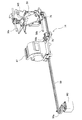
図4に示すようにフロントカバー73fには、スリット状開口77aが配置され、側枠フレーム70fにはセット面77bと、規制面77cが配置され外部からシート束Sを挿入するようになっている。図示の装置は図2に従って説明した処理トレイ37と、同一平面上で互いに隣接する位置でシート束を支持する位置に配置されている。
As shown in FIG. 4, a slit-shaped
これは、後述する処理トレイ37の端縁に沿って位置移動可能な綴じ処理ユニット47(ステープラユニット)を、処理トレイ37に隣接する位置に配置したセット面77bに位置移動させてマニュアルセットしたシート束を綴じ処理するためである。このためセット面77bは前述の処理トレイの紙載面47aと同一平面を形成する関係に配置されている。
This is because the binding processing unit 47 (stapler unit), which can be moved along the edge of the
上記スリット状開口77aは、セット面77b(処理トレイと同一平面)にシート束を挿入することが可能なようにフロントカバー73fに形成されている。このスリット状開口77aが形成されるフロントカバー73f(全体又は一部)は、装置フレーム70に開閉可能にヒンジ連結されている。
The slit-shaped
スリット状開口77aから手差し挿入されたシート束Sは、セット面77bに沿って綴じ位置に挿入され、綴じ位置の規制面77cに端面が突き当て規制される。これによって外部から挿入されたシート束Sは、その下面をセット面77bに支持され、その端面を規制面77cに突き当て規制されることによって所定の綴じ位置に位置決めされる。このセット面77bと規制面77cの内側にはステープル装置(綴じユニット)47が内蔵され、図示の装置は前述した処理トレイ37の綴じ位置と、セット面77bの綴じ位置との間で位置移動可能にガイドレールに支持され、シフトモータを備えた駆動機構で位置移動する。
The sheet bundle S manually inserted from the slit-shaped
[手差しセット部の綴じ処理動作]
綴じ処理動作について以下に説明する。後述する制御手段95は、処理トレイ37で綴じ処理しない動作モード(前述の第2、第3処理部B2,B3における後処理など)のときには綴じユニット47を、マニュアル綴じ位置、またはその近傍で待機させる。図示の装置は綴じユニット47のホームポジションを綴じ位置が側枠フレーム70fのフロント側に位置するマニュアル綴じ位置Mpに設定してある。
[Binding process operation of manual feed set section]
The binding processing operation will be described below. In an operation mode in which the binding process is not performed on the processing tray 37 (post-processing in the second and third processing units B2 and B3 described above), the
[パンチユニット]
シート搬入経路28に配置され、搬入口26から送られたシートにパンチ穴を穿孔するパンチユニット100について説明する。パンチユニット100は、シート搬入経路28のシート搬送方向に対して直交する方向に複数のパンチ部材101a〜101eを所定の間隔で配列して、選択された穴数をシートに穿孔する。
[Punch unit]
A description will be given of a
図5にパンチユニット100の全体構成を示す。パンチユニット100は、ユニットフレーム102と、このユニットフレームに上下動可能に配列された複数のパンチ部材101a〜101eと、各パンチ部材を上下動(穿孔方向に往復動)する駆動カム103と、この駆動カムを駆動する駆動モータM7で構成されている。
FIG. 5 shows the overall configuration of the
図示104は屑ボックスであり、パンチ部材101の下方に配置され穿孔屑紙片を収納する。この屑ボックス104は装置フレーム70(ユニットフレームとは異なる)にスライド可能にガイドレール105に取り付けられている。図示106は回転操作部材であり、パンチ部材101にジャムが発生したとき或いは駆動モータM7に異常が発生したとき駆動カム103を強制的に回転させてシートに食い込んだパンチ部材101を引き離す(引き剥がす)。このため回転操作部材106は、駆動カム103の回転軸107に連結された手動回転ツマミで構成してある。
図6に示すようにユニットフレーム102は、搬入経路28のシート搬送方向と直交する方向に所定長さの上部フレーム102aと、下部フレーム102bで構成されている。上部フレーム102aにはシート搬送方向と直交する方向(以下「搬送直交方向」と云う)に所定間隔で複数のパンチ部材101a〜101eが穿孔方向に往復動可能(上下動可能)に配置されている。下部フレーム102bには各パンチ部101に対向する位置に穿孔穴(ダイ)が形成されている。またユニットフレーム102には駆動回転軸107が配置され、この回転軸に各パンチ部材101を上下動する駆動カム103が取り付けられている。駆動回転軸107には駆動モータM7が伝動機構を介して連結されている。
As shown in FIG. 6, the
図示の駆動カム103は、駆動回転軸107に軸着され複数のパンチ部材101に対応する円筒カム部材で構成され、このカム部材に各パンチ部材が連結ピンで連結されている。そして駆動回転軸107の所定角度回転でパンチ部材101は穿孔方向に上下動するようになっている。このとき複数パンチ部材の第1グループ101b、101d(例えば2穴穿孔)は、駆動回転軸107の第1回転角度で穿孔方向に上下動し、異なる第2回転角度で第2グループ101a、101c、101e(例えば3穴穿孔)が穿孔方向に上下動する。
The illustrated drive cam 103 is constituted by a cylindrical cam member which is axially mounted on the
従って後述する制御手段95は駆動回転軸107を予め設定された角度範囲で往復回転すると第1グループのパンチ部材101b、101dに穿孔運動させ、異なる角度範囲で往復動すると第2グループのパンチ部材101a,101c,101eに穿孔運動させることが可能となる。
Therefore, the control means 95 described later causes the
上記屑ボックス104は、上記パンチ部材101の下方に配置され、装置フレームに設けたガイドレール105に支持され、装置フロント側(図示のものはフロントカバー73f)から着脱するようになっている。つまり装置フレーム70には前述したフロントカバー73fが開閉可能にヒンジ連結され、このフロントカバーを開蓋した状態で屑ボックス104を装置外に取り出すようになっている。
The
また前述した、駆動回転軸107には、駆動モータM7が減速機構(歯車伝動機構)を介して連結されていると共に、この回転軸107にはオペレータが手動で回転することが可能なように回転部材を側枠フレーム70fに設けられた開口部70xを通し、側枠フレーム70fのフロント側に配置している。そして装置フロント側には前述したフロントカバー73fが開閉可能に配置され、開蓋状態で回転操作部材106を操作可能になっている。このカバー開蓋状態では上記駆動モータM7には駆動電源が供給されない(遮断)ようになっている。
A drive motor M7 is connected to the
[パンチユニットのシフト機構]
上述のパンチユニット100は装置フレーム70に位置移動可動に取り付けられている。例えば装置フレーム70の両側枠フレーム70f,70r間を連結するステー部材70sに取り付けられ、ガイドレール108上を側枠フレーム70fに設けられた開口部70xをユニットフレームの上部フレーム102aが貫通してスライド移動可能に嵌合されている。そして上部フレーム102aの一部にラック109が一体形成され、装置フレーム側にマウントしたシフトモータM8と駆動ピニオン110でユニットフレーム全体が図6の状態から図7の状態に位置移動する。
[Shift mechanism of punch unit]
The above-mentioned
このようにパンチユニット100を搬送直交方向に位置移動可能に構成したのは搬入経路28に搬入されたシートは、(1)シートサイズの寸法誤差と(2)画像形成部におけるシートの位置ズレなどに原因して搬送直交方向に位置ズレされた状態となる。この位置ズレ量を補正することなくパンチ穴を穿孔すると仕上げ品位が著しく劣る。この搬入シートの位置ズレを補正するためには、パンチユニット100が搬送直交方向に位置移動するか、シートを直交方向に位置移動するか何れかが必要となる。
The configuration in which the
本発明は、シート搬入経路28に送られたシートに応じてパンチユニット100を搬送直交方向に位置移動することと、その移動方向を前述の手差しセット部77と同一の方向(装置フロント側)に設定することと、パンチユニット100の移動領域と手差しセット部77のシートセット領域を搬送直交方向に互いにオーバーラップするような配置関係としたことを特徴としている。
According to the present invention, the
[パンチユニットのシフト制御]
上述のパンチユニット100は搬入経路28に進入したシートの側端縁を基準に適合する穿孔穴位置に位置移動する。これは前述したようにシートの寸法誤差、搬入口に搬入するシートの位置ズレによってシート毎に穿孔穴位置が位置ズレするのを防止するためである。その方法は、(1)搬入経路28にシートの側端縁を提出するセンサアレイを配置し、画像形成装置Aから送られたシートサイズ情報とシート端縁を検出したアレイ信号からユニットの移動量を割り出して位置移動する。または(2)ユニットにシート側端縁を検出するセンサを設け、シートが搬入経路に進入したタイミングでユニットを搬送直交方向に移動させてセンサでシート側端縁を検出する。そしてその検出信号とシートサイズ情報からユニットの移動量を割り出して位置移動する。または(3)ユニットにシートサイズに対応する複数のセンサを配置し、シートが進入したタイミングでユニットを搬送直交方向に移動させてシートの側端縁を検出する。同時に検出したセンサからシートサイズを判別し、ユニット搬送直交方向に移動させる。
[Shift control of punch unit]
The above-described
図示の装置は上述の(3)の方法を採用している。これによってユニットの移動量を最小限に設定することが出来、装置のコンパクト化が達成される。このためユニットフレーム102には、シートの側端縁を検出するセンサS3(例えばJISB5縦)、S4(A4縦)、S5(B5横)、S6(A4横、A3縦)、がサイズ毎に配置されている。図示S1はシート搬入経路28に配置された入口センサであり、S2は出口センサ(排紙センサ)である。また図示HpSはユニットフレーム102に取り付けられたホームポジションセンサである。
The illustrated apparatus employs the method (3) described above. Thereby, the amount of movement of the unit can be set to a minimum, and the apparatus can be made compact. For this reason, sensors S3 (for example, JISB5 vertical), S4 (A4 vertical), S5 (B5 horizontal), and S6 (A4 horizontal, A3 vertical) for detecting the side edge of the sheet are arranged in the
後述する制御手段95は、搬入経路28にシート先端が進入したタイミングを入口センサS1で検出し、その検出信号でパンチユニット100をホームポジションから所定方向に位置移動する。そしてシート側端縁を検出したセンサの検出信号を受信し、その信号がいずれのセンサで発信されたかを判別して、シートサイズと側端縁を認識し、サイズに応じた穿孔位置を割り出す。そしてその穿孔位置にパンチユニット100を位置移動する。このためシフトモータM8は、回転量を検出するエンコーダが回転軸に連結されているか、ステッピングモータで構成されている。
The control means 95, which will be described later, detects the timing at which the leading edge of the sheet has entered the carry-in
特に図示の制御手段95は、入口センサS1でシート先端を検出した信号を基準にパンチユニット100をシート外側(図7矢印A方向)に移動し、シートの側端縁を検出する。次いでユニットを所定量オーバーランさせて停止し、シートセンタ側(矢印B方向)に移動する。そしてシートの側端縁を再度検出し、その検出信号を基準にユニットを所定量シートセンタ側に位置移動して穿孔位置に位置決めする。このようにパンチユニット100をシート外側(小サイズから大サイズ方向)に位置に移動した後にシートセンタ側に位置移動してシート側端縁を検出する。これによって、駆動機構中をバッククラッシュによる位置誤差を解消することができる。
In particular, the control means 95 shown moves the
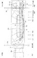
そこで本発明は、パンチユニット100の搬送直交方向移動領域(図6;Px)と、手差しセット部のセット面77aのシートセット領域(図6;Sx)を搬入経路28のシート搬送方向前後に距離を隔てた異なる位置に配置する。同時にパンチユニット100の移動領域Pxとセット面のセット領域Sxを段差Yを形成する異なる位置に配置する。
In the present invention, therefore, the transporting orthogonal direction moving area (FIG. 6; Px) of the
つまり領域Pxと領域Sxとはシートの搬送方向に異なる位置(間隔X)に配置され、同時に搬送方向と直交する高さ方向に異なる位置(段差Y)に配置されている。これと共に領域Pxと領域Sxとはシート幅方向に互いに重なり合う位置に(オーバーラップ量z)配置されている。これによってオーバーラップ量分だけ装置は小型コンパクトとなる。 That is, the area Px and the area Sx are arranged at different positions (interval X) in the sheet conveyance direction, and at the same time, arranged at different positions (step Y) in the height direction orthogonal to the conveyance direction. At the same time, the region Px and the region Sx are arranged at positions overlapping each other in the sheet width direction (overlap amount z). This makes the device small and compact by the amount of overlap.
「第1処理部の構成」
上述の第1処理部B1のシート搬入機構、シート位置決め機構、綴じ処理機構、シート束搬出機構の各構成について説明する。
"Configuration of the first processing unit"
The configuration of the sheet loading mechanism, the sheet positioning mechanism, the binding processing mechanism, and the sheet bundle unloading mechanism of the first processing unit B1 will be described.
「シート搬入機構」
図3に示すように排紙口35と処理トレイ37との間には、排紙口からシートを排紙方向と排紙反対方向にスイッチバック搬送する反転搬送機構41、42と、シートをトレイ側に案内するガイド機構(シートガイド部材)44と、シートを先端規制手段に案内する掻き込み回転体46が配置されている。
"Sheet loading mechanism"
As shown in FIG. 3, between the
反転搬送機構は、処理トレイ上に搬入するシートと係合する作動位置と離間した待機位置との間で上下動する昇降ローラ41と、シートを排紙反対方向に移送するパドル回転体42で構成され、この昇降ローラ41とパドル回転体42は揺動ブラケット43に取り付けられている。
The reversing transport mechanism includes an elevating
装置フレーム27aに回転軸36x(図示のものは排紙ローラ軸)を中心に揺動可能に揺動ブラケット43が配置され、このブラケットに昇降ローラ41とパドル回転体42の回転軸が軸受支持されている。そして揺動ブラケット43には図示ない昇降モータが連結され、マウントされている昇降ローラ41とパドル回転体42をシートと係合する作動位置とシートから離間した待機位置との間で上下動する。
A swinging
また昇降ローラ41をパドル回転体42には図示ない駆動モータが連結され、昇降ローラ41は正逆転方向に、パドル回転体42は逆転方向(排紙反対方向)に回転するように駆動が伝達されている。また処理トレイ37には、上記昇降ローラ41と互いに圧接する従動ローラ48が配置され、シートを単シート若しくは束状シートをニップして下流側に搬出する。
A drive motor (not shown) is connected to the elevating
上記昇降ローラ41と後述する掻き込み回転体46との間には、処理トレイ上に搬入されたシートの後端を規制手段38に向けて案内するガイド機構が配置され、図示のものは図3点線状態から実線状態に上下動するシートガイド部材44で構成され、このガイド部材44は排紙口35からシートが搬出されるときには点線位置に退避し、シート後端が排紙口35を通過した後にシート後端を処理トレイ上に案内する。このためシートガイド部材44には図示ない駆動機構が連結され、排紙口35から処理トレイ上にシート後端を案内するタイミングに応じて上下動する。
A guide mechanism for guiding the rear end of the sheet conveyed onto the processing tray toward the regulating means 38 is disposed between the elevating
「シート位置決め機構」
上記処理トレイ37には、所定の綴位置にシートを位置決めする位置決め機構38、39が配置され、図示のものはシート後端を突き当て規制するシート端規制手段38と、シート側縁を基準(センタ基準、片側サイド基準)位置に位置決めする側縁整合手段39で構成されている。
"Seat positioning mechanism"
シート端規制手段38は図3に示すようにシート後端を突き当て規制するストッパ部材で構成されている。また側縁整合部材39は図9に従って後述するが、図示の装置はシート搬入経路28からシートがセンター基準で排紙され、綴じモードに応じて同一のセンター基準で位置決めするか、片側サイド基準で位置決めする。
As shown in FIG. 3, the sheet end regulating means 38 is constituted by a stopper member which abuts and regulates the rear end of the sheet. The side
「側縁整合手段」
側縁整合板39F、39Rは図9に示すように処理トレイ37の紙載面37aから上方に突出し、シートの側縁と係合する規制面39xを有し、左右一対互いに対向するように配置する。そしてこの一対の側縁整合手段39を所定ストロークで往復動可能に処理トレイ37に配置する。このストロークは、最大サイズシートと最小サイズシートのサイズ差および整合した後のシート束を左右いずれかの方向に位置移動(オフセット搬送)するオフセット量によって設定する。
"Side alignment means"
As shown in FIG. 9, the side
つまり、左右の側縁整合手段39F,39Rの移動ストロークは、異なるサイズシートを整合するための移動量と、整合後のシート束のオフセット量で設定されている。なお、側縁整合板39F,39Rのオフセット移動は、コーナ綴じのときにはセンター基準で搬出されたシートを右コーナ綴じのときには右側に、左コーナ綴じのときには左側に所定量移動する。このオフセット移動は、処理トレイ37にシートが搬入された都度(搬入シート毎に)一枚ずつ実行する時と、シートを束状に整合した後に綴じ処理するために束毎移動するいずれかの方法を採用する。
That is, the moving stroke of the left and right side edge aligning means 39F and 39R is set by the moving amount for aligning different size sheets and the offset amount of the sheet bundle after the alignment. In the offset movement of the side
このため側縁整合手段39は、図9に示すように、右側縁整合部材39F(装置フロント側)と左側縁整合部材39R(装置リア側)で構成され、両側縁整合部材には、シート側端と係合する規制面39xが互いに接近方向又は離間方向に移動するように処理トレイ37に支持されている。処理トレイ37には表裏を貫通するスリット溝(不図示)が設けられ、このスリットからトレイ上面にシート側縁と係合する規制面39xを有する側縁整合手段39が摺動可能に嵌合されている。
Therefore, as shown in FIG. 9, the side
各側縁整合部材39F,39Rはトレイ背面側で複数のガイドコロ80(レール部材であっても良い)で摺動可能に支持され、ラック81が一体形成されている。左右のラック81にはピニオン82を介して整合モータM1,M2が連結されている。この左右の整合モータM1,M2はステッピングモータで構成され、図示しないポジションセンサで左右の側縁整合部材39F,39Rを位置検出し、その検出値を基準に各整合部材を左右いずれの方向にも、指定された移動量で位置移動できるように構成されている。
Each side
なお、図示のラック−ピニオン機構によることなく、各側縁整合部材39F,39Rをタイミングベルトに固定し、このベルトを左右往復動させるモータにプーリで連結する構成を採用することも可能である。
Instead of using the illustrated rack-pinion mechanism, it is also possible to employ a configuration in which the side
このような構成で後述する制御手段95は、画像形成装置Aなどから提供されるシートサイズ情報に基づいて左右の側縁整合部材39F,39Rを所定の待機位置(シートの幅サイズ+α位置)に待機させる。そして「マルチ綴じ」のときには、処理トレイ37上にシートを搬入し、シート端が後端規制手段38に突き当たったタイミングで整合動作を開始する。この整合動作は左右の整合モータM1,M2を同一量ずつ反対方向(接近方向)に回転する。
In such a configuration, the
すると処理トレイ37に搬入されたシートはシートセンタを基準に位置決めされ束状に積み重ねられる。このシートの搬入動作と整合動作の繰り返しでシートは処理トレイ37上に束状に部揃え集積される。このとき異なるサイズのシートは、センター基準で位置決めされる。また「コーナ綴じ」のときには、処理トレイ37上にシートを搬入し、シート端が後端規制手段38に突き当たったタイミングで整合動作開始する。この整合動作は綴位置側の整合板と、綴位置の反対側の整合板の移動量を異ならせる。そしてあらかじめ設定された綴位置にシートコーナが位置するように移動量を設定する。
Then, the sheets carried into the
「綴じ処理機構」
処理トレイ37には、紙載面37a上に集積したシート束を綴じ処理する綴じ処理機構47、60が配置されている。処理トレイ37はその紙載面37aに位置決め機構(シート端規制手段38と側縁整合手段39)で、所定の綴位置に位置決めされる。綴じ処理機構47,51は、シート束をステープル針で針綴じする第1綴じユニット47(第1綴じ手段;「ステープルユニット」以下同様)と、針なし綴じする第2綴じユニット51(第2綴じ手段;「エコ綴じユニット」以下同様)が選択的に綴位置に配置されるように構成されている。
"Binding mechanism"
In the
図2に示すように処理トレイ37には排紙口35から搬入されたシート後端部を綴じ処理する綴じ処理機構47,51が配置され、この綴じ機構は図8に示すように処理トレイ37の紙載面37aの後端部に沿って位置移動可能なステープルユニット(第1綴じユニット)47とエコ綴じユニット(第2綴じユニット)51で構成されている。
As shown in FIG. 2, the
図8には、処理トレイ上に配置されたステープルユニット(第1綴じユニット)47、エコ綴じユニット(第2綴じユニット)51を示す。図示の装置は図面上左側に位置するシートコーナに綴位置Cp1が設定してある。この綴位置Cp1に第1綴じユニット47と第2綴じユニット51が相反的に位置移動する。
FIG. 8 shows a staple unit (first binding unit) 47 and an eco-binding unit (second binding unit) 51 arranged on the processing tray. In the illustrated apparatus, a binding position Cp1 is set at a sheet corner located on the left side in the drawing. The first
このため第1綴じユニット47は装置フレーム27bに形成された第1走行レール53と第2走行レール54に沿って所定ストロークSL1で移動し、同様に第2綴じユニット51は装置フレーム57に配置された第1ガイドロッド56aと第2ガイドロッド56b(図12参照)に沿ってストロークSL2で移動するように配置されている。
Therefore, the first binding
図9は、処理トレイ37に搬入されたシートと、第1、第2綴じユニット47,51の移動ストロークを示す。処理トレイ37には異なるサイズのシートが最大サイズシートから最小サイズシートまでがセンター基準で搬入される。このシートを左右一対の側縁整合部材39F,39Rがシートの綴じ側縁(図示のものは左側縁)を基準に(異なるサイズのシートが一致するように)整合する。このため左右の整合部材39F,39Rはそれぞれ異なる駆動モータM1,M2に連結され、後述する制御手段95はシートサイズに応じて左右の整合部材39F,39Rの移動量を設定する。
FIG. 9 illustrates the sheet carried into the
なお後述する制御手段95は、シートコーナを綴じ処理する以外の綴じ処理、例えば後述するマルチ綴じモードのときにはセンター基準でシートを整合する。この場合には左右の整合部材39F,39Rは待機位置から同一量ずつシートセンタ寄りに位置移動することによってシートを綴位置に位置決めする。
Note that the control means 95, which will be described later, aligns sheets based on a center in a binding process other than the binding process of a sheet corner, for example, in a multi-binding mode which will be described later. In this case, the right and left aligning
図9に従って説明すると、第1綴じユニット47は、待機位置Wp1(第1待機位置)と綴位置Cp1の間の第1ストロークSL1で、第2綴じユニット51は待機位置Wp2(第2待機位置)と綴位置Cp1との間の第2ストロークSL2で移動する。つまり第1綴じユニット47は走行レール53,54(ガイド溝、ガイドロッドなど)に沿って待機位置Wp1と綴位置Cp1との間で往復動し、第2綴じユニット51はガイドロッド56a、56b(ガイド溝であっても良い)に沿って待機位置Wp2と綴位置Cp1との間で往復動する。
Referring to FIG. 9, the first binding
そして綴位置Cp1はシートコーナに設定(以下「設定綴位置」と云う)され、この位置に対し第1待機位置Wp1と第2待機位置Wp2は次の関係が成立するようにしてある。
(1)設定綴位置Cp1を挟んで第1待機位置Wp1と第2待機位置Wp2が反対側に位置するように設定する。
(2)第1待機位置Wp1は処理トレイ上で綴じ処理する最大サイズシートの外側か、若しくは処理トレイ上で設定綴位置Cp1から最も離れた綴じ処理位置(後述するマルチ綴位置Maまたはマニュアル綴位置Mp;最大遠隔綴位置)の何れかに設定する。
(3)第2待機位置Wp2は、設定綴位置に整合するシート側縁の外側(紙載面のシート載置エリア外)に設定する。
(4)第1待機位置Wp1と設定綴位置Cp1との間の第1ストローク長SL1は、第2待機位置Wp2と設定綴位置Cp1との間の第2ストローク長SL2より大きく(長く)が設定する。
Then, the binding position Cp1 is set at the sheet corner (hereinafter, referred to as "set binding position"), and the first standby position Wp1 and the second standby position Wp2 satisfy the following relationship with this position.
(1) The first standby position Wp1 and the second standby position Wp2 are set on opposite sides of the set binding position Cp1.
(2) The first standby position Wp1 is outside the maximum size sheet to be stapled on the processing tray, or a stapling position farthest from the set stapling position Cp1 on the processing tray (a multi-stitch position Ma or a manual stapling position described later). Mp; maximum remote binding position).
(3) The second standby position Wp2 is set outside the sheet side edge that matches the set binding position (outside the sheet placement area on the sheet placement surface).
(4) The first stroke length SL1 between the first standby position Wp1 and the set binding position Cp1 is set to be longer (longer) than the second stroke length SL2 between the second standby position Wp2 and the set binding position Cp1. I do.
このように設定綴位置Cp1に対して第1待機位置Wp1と第2待機位置Wp2を反対側に設定することにより一方のユニットが接近するときには他方のユニットは離れる方向に移動する(相反的退避接近動作)。またSL1>SL2に設定することによって第1綴じユニット47の綴じ処理位置(後述するマルチ綴位置Ma)を比較的自由に設定することが可能である。これに対し第2綴じユニット51は予め設定した綴位置でのみ綴じ処理する。これによって第1、第2綴じユニット47,51の総移動ストローク長を小さく設定することができ、装置を小型化することができる。
By setting the first standby position Wp1 and the second standby position Wp2 on opposite sides of the set binding position Cp1 as described above, when one unit approaches, the other unit moves away (reciprocal retreat approach). motion). By setting SL1> SL2, the binding processing position of the first binding unit 47 (multiple binding position Ma described later) can be set relatively freely. On the other hand, the second
そして後述する制御手段95は、第1綴じユニット47が設定綴位置Cp1のときには第2綴じユニットは待機位置Wp2に、第2綴じユニット51が設定綴位置Cp1のときには第1綴じユニットは待機位置Wp1に位置するように両ユニットを相反的に移動させる。
When the first binding
第1、第2綴じユニット47,51の相反的位置移動は、(1)それぞれ独立した駆動モータで移動ストロークに応じて回転量を異ならせるか、(2)同一の駆動源で第1綴じユニット47と第2綴じユニット51との移動量異ならせるかいずれかの方法を採用する。
The reciprocal position movement of the first and second
図10には、第1綴じユニット47と第2綴じユニット51を同一の駆動源で移動量を異ならせる形態を示す。装置フレーム27bには第1ユニットの移動領域(図10左右方向)に沿って左右一対のプーリ58a、58bが配置され、両プーリ間にタイミングベルト59(歯付ベルト)が架け渡してあり、一方のプーリ58aに駆動モータM3(ステッピングモータ)が連結してある。
FIG. 10 shows a mode in which the first binding
そして、他方のプーリ58bには差動手段(伝動手段)74を介して伝動ピニオン75が連結され、このピニオンに第2綴じユニット51のフレームに固定されたラック76が噛合している。そして差動手段74は、第1、第2ストロークSL1,SL2のストローク差に適合する伝動比の歯車機構か、滑りクラッチ機構か、この両機構の組み合わせで構成されている。
A
「ステープルの移動機構」
図3に示すように、装置フレーム70の側枠フレーム70fに設けられた開口部70xを貫通させて側枠フレーム70f,70rに固定されているステープルの装置フレーム(シャーシフレーム)27bに、ステープルユニット47が所定ストロークで移動可能にマウントされている。装置フレーム27bには、第1走行レール53と第2走行レール54が配置されている。第1走行レール53には走行レール面53xが、第2走行レール54には走行カム面54xが形成され、この走行レール面53xと走行カム面54xが互いに協同してステープルユニット47(以下この項では「移動ユニット」という)を所定ストロークで往復動可能に支持し、同時にその角度姿勢を制御している。
"Staple moving mechanism"
As shown in FIG. 3, the staple unit is attached to a staple device frame (chassis frame) 27b fixed to the side frame frames 70f and 70r through an
上記第1走行レール53と第2走行レール54は、移動ユニットの移動範囲で往復動するようにレール面53xと走行カム面54xが形成されている(図5参照)。移動ユニット47(ステープルユニット)には、駆動モータ(走行モータ)M3に連結されたタイミングベルト59が固定されている。このタイミングベルト59は装置フレーム27bに軸支した一対のプーリ58a、58bに巻回され、プーリの一方に駆動モータM3が連結されている。従って、駆動モータM3の正逆転でステープルユニット47はストロークSL1で往復動することとなる。
The first traveling
上記移動ユニット47は、上記第1、第2走行レール53,54に次のように係合している。図3に示すように、移動ユニット47には、走行レール面53xと係合する第1転動コロ83(レール嵌合部材)と、走行カム面54xと係合する第2転動コロ84(カムフォロア部材)が設けられている。これと共に移動ユニット47にはフレーム27bのサポート(支持)面と係合するボール形状の滑動コロ47x(図示のものは2箇所)が形成されている。また、移動ユニット47には底枠部フレームの底面と係合するガイドコロ47yが形成してあり底枠フレーム27bから移動ユニット47が浮上するのを防止している。
The moving
以上の構成から移動ユニット47は底枠フレーム27bに滑動コロ47xとガイドコロ47yで移動可能に支持されている。これと共に第1転動コロ83は走行レール面53xに、第2転動コロ84は走行カム面54xに沿って回転しながらレール面53xとカム面54xに倣って走行移動する。
From the above configuration, the moving
「スタックトレイ昇降機構」
シート後処理装置Bは図11に示すように外装カバー73に上記第1トレイ49が備えられている。この第1トレイ49はシートの積載量に応じて上下昇降するように構成されている。このため第1トレイ49の基端部には図11に示すように上下2個所にガイドコロ85が設けてあり、このガイドコロが装置フレーム27に設けた昇降ガイド86に嵌合支持されている。そしてこの第1トレイ49の基端部は昇降ベルト87に連結され、この昇降ベルトは上下一対のプーリ88a、88bに支持されている。このプーリの一方(駆動側プーリ)88aには昇降モータM4が連結されている。従って昇降モータM4を回転制御することによって第1トレイ49はシートの積載量に応じて上下昇降することとなる。
"Stack tray elevating mechanism"
The sheet post-processing apparatus B is provided with the
「シート束搬出機構」
上述の処理トレイ37には綴じ処理したシート束を下流側の第1トレイ49に向けて搬出するシート束搬出機構が配置されている。シート束を下流側に搬送する手段としては、互いに圧接するローラ対で搬送する方法(搬出ローラ手段)と、トレイ面に沿って上流側から下流側に移動する押出部材でシート後端を押し出すコンベア手段が知られている。図示の装置はその両手段を採用している。
"Sheet bundle unloading mechanism"
A sheet bundle unloading mechanism that unloads the bound sheet bundle toward the
図12にシート束搬出機構示し、処理トレイ37に沿って上流側に位置する綴位置(処理位置)から下流側のスタックトレイ(第1トレイ)49に移送する押出突起38と、押出突起を移動するコンベアベルト38vと、その駆動モータM6でコンベア手段が構成されている。処理トレイ37にはその搬出口(紙載面37aと第1トレイ49の境界)に従動ローラ48が配置され、この従動ローラに圧接する昇降ローラ41が前述した構成で対向配置され、この従動ローラ48と昇降ローラ41とで搬出ローラ手段を構成している。
FIG. 12 shows a sheet bundle unloading mechanism, in which the
従って、処理トレイ37にはシート束を上流側から下流側に押し出すように移送するコンベア手段38、38vと、シート束をニップして搬出する搬出ローラ手段48,41が配置されていることとなる。図12(a)はシート束が処理トレイ上の綴位置に位置する状態を示し、このときコンベア手段38、38vと搬出ローラ手段48,41は作動状態に置かれている。同図(b)は、シート束を処理位置から下流側に移送する途中の状態を示し、シート束は押出突起38の位置移動と、搬出ローラ手段48,41の回転で下流側に送られる。同図(c)は、シート束を下流側の第1トレイ49に搬出する直前の状態を示し、処理トレイ上でシート束は、搬出ローラ手段48,41の回転で下流側に徐々に(低速で)送られる。このとき押出突起38は図示位置に待機し、初期位置に復帰(後退移動)する。
Accordingly, the
「ステープルユニットの構成」
上述のステープルユニットについて、その構成を図13(a)に従って説明する。ステープルユニット47はシート後処理装置Bとは別にユニット構成されている。ボックス形状のユニットフレーム47aと、このフレームに揺動可能に軸支持されたドライブカム47dと、このドライブカムを回動する駆動モータM4がユニットフレーム47aにマウントされている。
"Staple Unit Configuration"
The configuration of the above-described staple unit will be described with reference to FIG. The
そしてドライブカム47dには、ステープルヘッド47bとアンビル部材47cが綴位置に対向配置され、ステープルヘッド47bはドライブカム47dに付勢スプリング(不図示)で上方の待機位置から下方のステープル位置(アンビル部材)に上下動する。そしてユニットフレームには針カートリッジ52が着脱可能に装着されている。
The
針カートリッジ52には直線状のブランク針が収納され、針送り機構でステープルヘッド47bに針を供給する。ステープルヘッド部47bには、内部に直線針をコ字状に折り曲げるフォーマ部材と、折り曲げられた針をシート束に圧入するドライバーが内蔵されている。このような構成により駆動モータM4でドライブカム47dを回転し、付勢スプリングに蓄勢する。そして、回転角度が所定角度に達するとステープルヘッド部47bは勢いよくアンビル部材47c側に下降する。この動作でステープル針はコ字状に折り曲げられた後にドライバーでシート束に刺入する。そしてその先端はアンビル部材47cで折り曲げられステープル綴じされる。
A linear blank needle is stored in the
また、針カートリッジ52とステープルヘッド47bとの間には針送り機構が内蔵されこの針送り部には針なしを検出するセンサ(エンプティセンサ)が配置されている。またはユニットフレーム47aには、針カートリッジ52が挿入されているか否かを検出するカートリッジセンサ(不図示)の配置されている。
Further, a needle feed mechanism is built in between the
図示の針カートリッジ52は、ボックス形状のカートリッジに帯状に連結したステープル針を積層状に積み重ねて収納する構造と、ロール状に収納する構造が採用されている。またユニットフレーム47aには、上述の各センサを制御する回路と駆動モータM4を制御する回路基盤が設けられ、針カートリッジ52が収納されていないとき、ステープル針がエンプティのときには、警告信号を発するようになっている。またこのステープル制御回路は、ステープル針信号でステープル動作を実行するように駆動モータM4を制御し、ステープルヘッドが待機位置からアンビル位置に移動して、再び待機位置に復帰したときに「動作終了信号」を発信するように構成されている。
The illustrated
「針なし綴じユニットの構成」
上述の針なし綴じユニット51についてその構成を図13(b)に従って説明する。シート束を金属針を用いないで綴じ処理する針なし綴じ手段としては、互いに噛み合う凹凸面を有する加圧部材でシート束を表裏から挟圧して紙葉相互を結束する手段(プレスバインド綴じ装置)と、シート束にスリット状切り込みを形成して紙葉相互を折り合わせて結束する手段(切込折り綴じ装置;特開2011−256008号公報参照)と、植物性の樹脂紐で綴じ合わせる手段(樹脂紐結束装置)などが知られている。これらの綴じ方法は金属針を使用することなく、シート束を利用して結束していることからエコ綴じ結束方法として知られている。以下その一例としてプレスバインド機構について説明する。
"Structure of stapleless binding unit"
The configuration of the stapleless
プレスバインド機構としては互いに圧接離間自在の加圧面51b、51cに凹凸面を形成してシート束を表裏から挟圧することによって紙葉相互間を変形させて結束する。図13(b)にはプレスバインドユニット51を示し、ベースフレーム部材51aに可動フレーム部材51dを揺動可能に軸支持し、支軸51xで両フレームは圧接離間可能に揺動する。可動フレーム部材51dにはフォロワーコロ60aが配置され、このフォロアコロはベースフレーム部材51aに配置されているドライブカム60bが係合している。
As a press binding mechanism, unevenness is formed on the
上記ドライブカム60bにはベースフレーム部材51aに配置した駆動モータM5が減速機構を介して連結され、モータの回転でドライブカム60bが回転し、そのカム面(図示のものは偏心カム)で可動フレーム部材51dを揺動させるように構成されている。
A drive motor M5 arranged on the
そしてベースフレーム部材51aには下部加圧面51cが、可動フレーム部材51dには上部材加圧面51bがそれぞれ対向する位置に配置されている。このベースフレーム部材51aと可動フレーム部材51dの間には図示しないが付勢スプリングが配置され、両加圧面が離間する方向に付勢されている。
The lower
上記上部加圧面51bと下部加圧面51cは図13(b)中に示す拡大図のように一方に突起条が、他方にはこれと適合する凹陥溝が形成されている。この突起条と凹陥溝は所定長さの畝(リブ)形状に形成されている。従って上部加圧面51bと下部加圧面51cで挟圧されたシート束は波板形状に変形して密着することとなる。上記ベースフレーム部材51a(ユニットフレーム)には図示しないポジションセンサが配置され、上下加圧面51b、51cが加圧位置か離間位置にあるか否かを検出するように構成されている。
As shown in the enlarged view of FIG. 13B, the upper
このように構成されたプレスバインドユニット(エコ綴じユニット;第2綴じユニット)51は、側枠フレーム70rに取り付けられた装置フレーム57に配置された第1、第2ガイドロッド56a、56b(溝であっても良い)に移動可能に配置され、前述したように側枠フレーム70f,70rの間に位置する処理トレイ37上に集積されたシートの設定綴位置Cp1と側枠フレーム70rのリヤ側に位置する第2待機位置Wpとの間で往復動する。
The press bind unit (eco-binding unit; second binding unit) 51 configured as described above includes first and
[制御構成の説明]
図14に従って図1の画像形成システムにおける制御構成について説明する。図14に示す画像形成システムは、画像形成装置Aの制御部90(以下「本体制御部」という)とシート後処理装置Bの制御部95(以下「綴じ処理制御部」という)を備えている。本体制御部90は印字制御部91と給紙制御部92と入力部93(コントロールパネル)を備えている。
[Description of control configuration]
The control configuration in the image forming system of FIG. 1 will be described with reference to FIG. The image forming system illustrated in FIG. 14 includes a
そして入力部93(コントロールパネル)から「画像形成モード」と「後処理モード」の設定を行う。画像形成モードはカラー・モノクロ印刷、両面・片面印刷などのモード設定と、シートサイズ、シート紙質、プリントアウト部数、拡大・縮小印刷、などの画像形成条件を設定する。また「後処理モード」は、例えば「プリントアウトモード」「ステープル綴じ処理モード」「エコ綴じ処理モード」「ジョグ仕分けモード」などに設定する。なお図示の装置には「マニュアル綴じモード」が設けられ、このモードは画像形成装置Aの本体制御部90とは別にオフラインでシート束の綴じ処理動作を実行する。
Then, “image forming mode” and “post-processing mode” are set from the input unit 93 (control panel). In the image forming mode, mode settings such as color / monochrome printing, double-sided / single-sided printing, and image forming conditions such as sheet size, sheet quality, number of printouts, enlargement / reduction printing, and the like are set. The “post-processing mode” is set to, for example, “print-out mode”, “staple binding mode”, “eco-binding mode”, “jog sorting mode”, or the like. The illustrated apparatus is provided with a “manual binding mode”, in which the sheet bundle binding processing operation is executed offline separately from the main
また、本体制御部90は綴じ処理制御部95に後処理モードとシート枚数、部数情報及び画像形成するシートの紙厚さ情報などをデータ転送する。これと同時に本体制御部90は画像形成を終了する都度、ジョブ終了信号を綴じ処理制御部95に転送する。
Further, the main
上述の後処理モードについて説明すると、上記「プリントアウトモード」は、排紙口35からのシートを、綴じ処理することなく処理トレイ37を介してスタックトレイ49に収容する。この場合にはシートを処理トレイ37に重ね合わせて集積し、本体制御部90からのジョグ終了信号で集積後のシート束をスタックトレイ49に搬出する。
The above-described post-processing mode will be described. In the “print-out mode”, the sheet from the
上記「ステープル綴じ処理モード」は、排紙口35からのシートを処理トレイ上に集積して部揃えし、このシート束を綴じ処理した後にスタックトレイ49に収容する。この場合には画像形成されるシートは原則として同一紙厚さで同一サイズのシートにオペレータによって指定される。このステープル綴じ処理モードは、「マルチ綴じ」「右コーナ綴じ」「左コーナ綴じ」のいずれかが選択され指定される。各綴じ位置については前述した通りである。
In the “staple binding processing mode”, the sheets from the
上記「ジョグ仕分けモード」は、画像形成装置Aで画像形成されたシートをオフセットさせて集積するグループと、オフセットさせることなく集積するグループとに区分けられ、スタックトレイには交互にオフセットされたシート束とオフセットされないシート束が積み上げられる。 The “jog sorting mode” is divided into a group in which sheets formed by image formation in the image forming apparatus A are offset and stacked, and a group in which sheets stacked without offset are stacked. And a sheet bundle that is not offset is stacked.
「マニュアル綴じモード」
外装カバーには装置フロント側に、オペレータが綴じ処理するシート束をセットする手差しセット部が設けられている。この手差しセット部のセット面には、セットされたシート束を検出するセンサが配置され、このセンサからの信号で後述する綴じ処理制御部95は、ステープラユニット47をマニュアル綴じ位置に位置移動する。そしてオペレータが作動スイッチを押下すると、綴じ処理を実行するように構成されている。
"Manual binding mode"
The outer cover is provided on the front side of the apparatus with a manual feed setting unit for setting a sheet bundle to be bound by an operator. A sensor for detecting the set sheet bundle is disposed on the setting surface of the manual feed setting unit, and a binding
従ってこのマニュアル綴じモードは綴じ処理制御部95と本体制御部90とはオフラインで制御される。ただし、マニュアル綴じモードとステープル綴じモードが同時に実行するときには、いずれか一方が優先するようにモード設定されている。
Therefore, in the manual binding mode, the binding
[綴じ処理制御部]
綴じ処理制御部95は、画像形成制御部90で設定された後処理モードに応じてシート後処理装置Bを動作させる。図示の綴じ処理制御部95は制御CPU(以下単に制御手段という)で構成されている。制御CPU95には、ROM96とRAM97が連結され、ROM96に記憶された制御プログラムとRAM97に記憶された制御データで後述する排紙動作を実行する。このため、制御CPU95には前述したすべての駆動モータの駆動回路に連結され、各モータを起動、停止および正逆転制御する。
[Binding control unit]
The binding
[排紙動作モード]
画像形成装置Aの制御部(本体制御部)90では画像形成条件と同時に画像形成したシートの後処理(仕上げ処理)モードを設定する。図示の装置は「ステープル綴じモード」と「エコ綴じモード」と「ジョグ仕分けモード」と「製本仕上げモード」と「プリントアウトモード」と「割込みモード」と「マニュアル綴じモード」に設定される。以下各モードの動作について説明する。
[Output mode]
The control section (main body control section) 90 of the image forming apparatus A sets a post-processing (finishing processing) mode of the sheet on which the image is formed simultaneously with the image forming condition. The illustrated apparatus is set to “staple binding mode”, “eco binding mode”, “jog sorting mode”, “bookbinding finishing mode”, “printout mode”, “interruption mode”, and “manual binding mode”. The operation of each mode will be described below.
図15は、第1処理部B1の処理トレイ37に集積されたシート束にステープル綴じ若しくはエコ綴じして下流側の第1トレイ49に収納する動作フローの説明図である。図16は、シートを部毎にジョグ区分けする排紙モードの説明図であり、第3処理部(シート搬入経路)B3のジョグ機構(ローラシフト機構;不図示)で排紙直交方向にオフセットした後に下流側の第3トレイ71に収納する動作フローの説明図である。図17は、第2処理部B2でシートを製本仕上げする製本処理排紙モードの説明図である。
FIG. 15 is an explanatory diagram of an operation flow of stapling or eco-binding a sheet bundle stacked on the
「第1処理部におけるステープル綴じモードとエコ綴じモード」
図15に従って説明すると、画像形成装置Aのコントロールパネル93などで後処理モードの設定が行われる(St01)。シート後処理装置Bの制御手段95は、後処理モード設定情報に基づいて(St02)、エコ綴じ処理が指定されたときには第2綴じユニット51を移動する(St05)。またステープル綴じ処理が指定されたときには第1綴じユニット47を移動する(St06)。
"Staple binding mode and eco-binding mode in the first processing unit"
Referring to FIG. 15, the post-processing mode is set on the
ステープル綴じ処理を実行するときには第1綴じユニット47を設定綴位置Cp1に移動し、第2綴じユニット51を第2待機位置Wp2に移動する。なおこのユニット位置がホームポジションとして設定されているときには、各ユニットがホームか否かを確認して移動する。
When executing the staple binding process, the first binding
次に、画像形成装置Aは画像を形成し、そのシートを排出する(St07,St08)。シート後処理装置Bは、搬入口26に送られた画像形成シートを受け入れ、下流側に搬送する(St09)。なおこのときパンチ処理が指定(St10)されているときには制御手段95は、シートを穿孔位置で一時的に停止(St11)する。そして、パンチユニット100を排紙直交方向に移動し、シートの側端縁をセンサで検出して所定の穿孔位置を割り出した後にパンチユニット100を停止して穿孔動作を実行する(St13)。
Next, the image forming apparatus A forms an image and discharges the sheet (St07, St08). The sheet post-processing apparatus B receives the image forming sheet sent to the carry-in
なお、パンチ処理が指定されていないときには制御手段95は搬入口側シートを受け入れ、経路排紙口に搬送する。そして処理トレイ37に搬入し位置決め手段で所定位置に位置決めする(St15)。制御手段95は排紙口35に送られたシートを処理トレイ37の紙載面上に積み重ねて収納する(St07〜St15)。そして画像形成装置Aからジョグ終了信号を受信する(St16)と、制御手段95は第1綴じユニット47又は第2綴じユニット51に綴じ処理指示信号を発信する。すると第1綴じユニット47又は第2綴じユニット51は綴じ処理を実行する(St17)。
When the punching process is not specified, the control means 95 receives the carry-in side sheet and conveys the sheet to the path paper discharge port. Then, it is carried into the
制御手段95は第1(又は第2)綴じユニット47、51から綴じ処理終了信号を受信すると、シート束搬出手段で綴じ処理されたシート束を下流側の第1トレイ49に収納する(St18)。そして第1トレイ49に配置され紙面レベルの検出センサ(不図示)で積載高さを検出し、所定角度超えるときには第1トレイ49を繰り下げる(St20)。次いで制御手段95は、次ジョブがあるか否かを判断し(St21)、動作を完了する。
Upon receiving the binding processing end signal from the first (or second) binding
図16に従ってジョグ仕分け排紙モードを説明する。制御手段95はシート搬入経路28の搬入口26に送られたシート(St22〜St24)を、パンチ処理が指定されているとき(St25)には、シートを穿孔位置で一時的に停止(St26)する。そして、パンチユニット100を排紙直交方向に移動(St27)し、シートの側端縁をセンサで検出して所定の穿孔位置を割り出した後にパンチユニット100を停止して穿孔動作を実行する(St28)
The jog sorting / discharge mode will be described with reference to FIG. The control means 95 temporarily stops the sheet (St22 to St24) sent to the carry-in
次いで制御手段95は、シートを第3排紙パス30から第3トレイ71に搬出(St29)するためにローラユニットを排紙方向に回転する(St30)。そしてシートは偶数ページのとき(St31,St32)にはローラユニットを停止(St33)し、シートをニップした状態で排紙直交方向にあらかじめ設定されたオフセット量だけ位置移動する(St34)。その後制御手段95は再びローラユニットを排紙方向に回転(St35)する。このとき、第1経路切換え手段33はシートを搬入口26から第3排紙パス30に、案内する方向にシフトされ、シートは第3トレイ71に集積される(St36)。
Next, the control means 95 rotates the roller unit in the paper discharge direction to carry out the sheet from the third
図17に従って製本処理排紙モードについて説明する。前述と同様に画像形成されたシートは、シート搬入経路28に導かれる。このシートは搬入口26から第2処理部B2に案内され、先端規制ストッパ67に突き当て規制される。このとき制御手段95は予めシートの排紙方向サイズを画像形成装置Aから情報受信して先端規制ストッパ67の位置を設定してある。
The bookbinding discharge mode will be described with reference to FIG. The sheet on which an image has been formed in the same manner as described above is guided to the sheet carry-in
第2処理部B2に集積されたシートは、画像形成装置Aからのジョブ終了信号で綴じユニット(中綴じユニット)をシート中央部に移動して綴じ処理する。1箇所または2箇所など綴じ処理が完了した段階でシート束を折位置に移動し、折りロール64を回転する。折りブレード65を折り方向に進入させ所定量折りローラ64を回転した段階で折りブレード65を後退させる。すると折り処理シートは下流側の排紙ローラ69で排紙方向に送り出され第2トレイ61に収納される。
The sheets stacked in the second processing unit B2 are subjected to the binding process by moving the binding unit (saddle binding unit) to the center of the sheet in response to the job end signal from the image forming apparatus A. When the binding process is completed at one or two places, the sheet bundle is moved to the folding position, and the
26 搬入口
27 装置ハウジング
28 シート搬送経路
37 処理トレイ
47 綴じ手段
49 スタックトレイ
70 装置フレーム
70f 側枠フレーム(フロント側)
70r 側枠フレーム(リヤ側)
73f フロントカバー(開閉カバー)
73r リアカバー
77 手差しセット部
77a スリット状開口
100 パンチユニット
101 パンチ部材(101a〜101e)
102 ユニットフレーム
103 駆動カム
104 屑ボックス
105 ガイドレール
106 回転操作部材
107 回転軸
108 ガイドレール
109 ラック
110 ピニオン
M7 駆動モータ
M8 シフトモータ(シフト手段)
26
70r Side frame (rear side)
73f Front cover (open / close cover)
73r
102 Unit frame 103
Claims (8)
シートを搬送するための搬送経路と、
前記搬送経路においてシートが搬送される搬送方向と直交するシート幅方向において一方側に側枠フレームを有する、装置フレームと、
前記シート幅方向において前記側枠フレームの前記一方側に配置されるカバーに形成される開口と、前記シート幅方向において前記側枠フレームの前記一方側に配置され、前記シート処理装置の外部から前記開口を介して挿入されたシート束の下面を支持するセット面と、前記シート幅方向において前記側枠フレームの前記一方側に配置され、前記開口を介して挿入された該シート束の端部が突き当たることによって該シートの位置を規制する規制面と、を有するセット部と、
前記セット部とは異なる位置に配置され、前記搬送経路から搬送されたシートを積載する積載手段と、
前記セット部にセットされたシート束を綴じることが可能であるとともに、前記積載手段に積載されたシート束を綴じることが可能な綴じ手段と、
前記搬送経路に配置されるとともに、前記シート幅方向に位置移動可能に前記装置フレームに取り付けられ、シートを穿孔するパンチ部材を有するパンチユニットと、を有し、
前記パンチユニットが前記シート幅方向において前記一方側に最も移動した状態において、前記シート幅方向における前記パンチユニットの前記一方側の端部は、前記シート幅方向において、前記側枠フレームよりも、前記一方側に位置しており、
前記搬送経路においてシートが搬送される前記搬送方向と直交する前記シート幅方向において、前記セット部は、前記セット部においてシート束がセットされる領域であるシートセット領域が前記パンチユニットの前記端部の移動領域と重なり合うように配置されている、
ことを特徴とするシート処理装置。 A sheet processing apparatus for processing a sheet, comprising:
A conveyance path for conveying the sheet,
An apparatus frame having a side frame on one side in a sheet width direction orthogonal to a conveyance direction in which a sheet is conveyed in the conveyance path,
An opening formed in a cover arranged on the one side of the side frame in the sheet width direction, and an opening formed on the one side of the side frame in the sheet width direction, and from outside the sheet processing apparatus; A set surface that supports the lower surface of the sheet bundle inserted through the opening, and an end of the sheet bundle inserted through the opening is disposed on the one side of the side frame in the sheet width direction. A setting portion having a regulating surface that regulates the position of the sheet by abutting;
A loading unit that is disposed at a position different from the setting unit and that loads the sheet transported from the transport path;
A binding unit capable of binding the sheet bundle set in the setting unit and binding the sheet bundle stacked in the stacking unit;
The Rutotomoni disposed conveying path, wherein attached to position movable in the apparatus frame in the seat width direction, it has a punch unit having a punching member for perforating the sheet, and
In a state where the punch unit is moved most to the one side in the sheet width direction, the end of the one side of the punch unit in the sheet width direction is more than the side frame in the sheet width direction. Located on one side,
In the sheet width direction orthogonal to the conveying direction of the sheet is transported in the transport path, the set portion, a sheet set region is a region where the sheet bundle is set in the set section is the end of the punch unit Are arranged to overlap the moving area of
A sheet processing apparatus, characterized in that:
前記搬送経路に搬送されたシートの端縁の、前記検出手段による検出結果に基づいて、前記パンチユニットは、シートを穿孔するための穿孔位置に移動する、
ことを特徴とする請求項1に記載のシート処理装置。 Having a detecting means for detecting a sheet edge,
The punch unit moves to a punching position for punching a sheet, based on a detection result of the edge of the sheet transported to the transport path by the detection unit .
The sheet processing apparatus according to claim 1 , wherein:
ことを特徴とする請求項1または2に記載のシート処理装置。 The binding unit is configured to be movable between a first position for binding the sheet bundle set in the setting unit and a second position for binding the sheet bundle stacked on the stacking unit.
The sheet processing apparatus according to claim 1 or 2, characterized in that.
前記ジャム解除部材は、前記シート幅方向において前記セット部の前記シートセット領域と重なり合うように配置されている、
ことを特徴とする請求項1から3のいずれか1項に記載のシート処理装置。 The punch unit has a jam release member that is operated when the jam release operation is performed,
The jam release member is disposed so as to overlap with the sheet setting area of the setting unit in the sheet width direction.
The sheet processing apparatus according to any one of claims 1 to 3 , wherein:
シートを穿孔するための前記パンチ部材と、
前記パンチ部材を、シートを穿孔する際の穿孔方向と前記穿孔方向とは逆の方向とに、回転することによって往復移動させる移動手段と、
を有し、
前記ジャム解除部材は、前記移動手段を回転させる部材である、
ことを特徴とする請求項4に記載のシート処理装置。 The punch unit ,
The punch member for punching a sheet,
A moving means for reciprocating the punch member by rotating the punch member in a punching direction when punching a sheet and in a direction opposite to the punching direction,
Has,
The jam release member is a member that rotates the moving unit,
The sheet processing apparatus according to claim 4 , wherein:
ことを特徴とする請求項4または5に記載のシート処理装置。 The cover is an opening / closing cover that makes the jam release member operable in the open state.
The sheet processing apparatus according to claim 4 or 5, characterized in that.
ことを特徴とする請求項1から6のいずれか1項に記載のシート処理装置。 The set unit is set with a sheet bundle manually inserted from outside the apparatus through the opening .
The sheet processing apparatus according to any one of claims 1 to 6 , wherein:
前記画像形成装置から送られたシートを処理する処理部と、
から構成され、
前記処理部は、請求項1から7のいずれか1項に記載のシート処理装置であることを特徴とする画像形成システム。 An image forming apparatus for forming an image on a sheet,
A processing unit that processes a sheet sent from the image forming apparatus;
Composed of
Wherein the processing unit, an image forming system, which is a sheet processing apparatus according to any one of claims 1 to 7.
Priority Applications (5)
| Application Number | Priority Date | Filing Date | Title |
|---|---|---|---|
| JP2013260097A JP6639768B2 (en) | 2013-12-17 | 2013-12-17 | Sheet processing apparatus and image forming system using the same |
| US14/570,692 US9567183B2 (en) | 2013-12-16 | 2014-12-15 | Sheet processing apparatus and image forming system having the same |
| US15/398,336 US10071876B2 (en) | 2013-12-16 | 2017-01-04 | Sheet processing apparatus and image forming system having the same |
| US16/054,347 US10472198B2 (en) | 2013-12-16 | 2018-08-03 | Sheet processing apparatus and image forming system having the same |
| US16/592,404 US10829336B2 (en) | 2013-12-16 | 2019-10-03 | Sheet processing apparatus and image forming system having the same |
Applications Claiming Priority (1)
| Application Number | Priority Date | Filing Date | Title |
|---|---|---|---|
| JP2013260097A JP6639768B2 (en) | 2013-12-17 | 2013-12-17 | Sheet processing apparatus and image forming system using the same |
Related Child Applications (1)
| Application Number | Title | Priority Date | Filing Date |
|---|---|---|---|
| JP2018096725A Division JP6683760B2 (en) | 2018-05-21 | 2018-05-21 | Sheet processing apparatus and image forming system using the same |
Publications (3)
| Publication Number | Publication Date |
|---|---|
| JP2015117084A JP2015117084A (en) | 2015-06-25 |
| JP2015117084A5 JP2015117084A5 (en) | 2017-01-05 |
| JP6639768B2 true JP6639768B2 (en) | 2020-02-05 |
Family
ID=53530174
Family Applications (1)
| Application Number | Title | Priority Date | Filing Date |
|---|---|---|---|
| JP2013260097A Active JP6639768B2 (en) | 2013-12-16 | 2013-12-17 | Sheet processing apparatus and image forming system using the same |
Country Status (1)
| Country | Link |
|---|---|
| JP (1) | JP6639768B2 (en) |
Families Citing this family (2)
| Publication number | Priority date | Publication date | Assignee | Title |
|---|---|---|---|---|
| JP6384615B2 (en) * | 2015-08-06 | 2018-09-05 | 京セラドキュメントソリューションズ株式会社 | Punching device, sheet processing device, and image forming system |
| CN108290698B (en) * | 2015-12-25 | 2020-08-07 | 佳能精技立志凯株式会社 | Sheet binding processing apparatus |
Family Cites Families (6)
| Publication number | Priority date | Publication date | Assignee | Title |
|---|---|---|---|---|
| JP4626901B2 (en) * | 2000-05-01 | 2011-02-09 | リコーエレメックス株式会社 | Sheet aligner |
| JP2002179330A (en) * | 2000-12-13 | 2002-06-26 | Ricoh Co Ltd | Paper sheet working device |
| JP2004069884A (en) * | 2002-08-05 | 2004-03-04 | Brother Ind Ltd | Image forming apparatus equipped with image reading means |
| JP4560602B2 (en) * | 2004-09-09 | 2010-10-13 | ケイアールディーシー・カンパニー・リミテッド | Multi-staple device |
| JP2008260602A (en) * | 2007-04-11 | 2008-10-30 | Kyocera Mita Corp | Punch device, image forming device with it, and post-processor |
| JP5402299B2 (en) * | 2009-06-24 | 2014-01-29 | 富士ゼロックス株式会社 | Image forming apparatus and recording material processing apparatus |
-
2013
- 2013-12-17 JP JP2013260097A patent/JP6639768B2/en active Active
Also Published As
| Publication number | Publication date |
|---|---|
| JP2015117084A (en) | 2015-06-25 |
Similar Documents
| Publication | Publication Date | Title |
|---|---|---|
| JP6321368B2 (en) | Sheet binding apparatus and image forming system provided with the same | |
| JP6235900B2 (en) | Sheet binding processing apparatus and image forming system using the same | |
| US10472198B2 (en) | Sheet processing apparatus and image forming system having the same | |
| JP6223164B2 (en) | Sheet processing apparatus and image forming system provided with the same | |
| JP2015118153A5 (en) | ||
| JP2015117076A5 (en) | ||
| JP6655863B2 (en) | Sheet bundle binding device and image forming system having the same | |
| JP6655864B2 (en) | Sheet conveying device and image forming system provided with the same | |
| JP6334860B2 (en) | Sheet bundle binding processing apparatus and image forming system provided with the same | |
| JP2015016971A5 (en) | ||
| JP2015117075A (en) | Sheet postprocess device and image formation system using the same | |
| JP6639768B2 (en) | Sheet processing apparatus and image forming system using the same | |
| JP6689320B2 (en) | Sheet processing apparatus and image forming system including the same | |
| JP6638047B2 (en) | Sheet processing apparatus and image forming system using the same | |
| JP2015117084A5 (en) | ||
| JP5271676B2 (en) | Sheet folding apparatus, post-processing apparatus using the same, and image forming system | |
| JP6412628B2 (en) | Sheet processing apparatus and image forming system using the same | |
| JP6950027B2 (en) | Sheet processing device and image formation system using it | |
| JP6263377B2 (en) | Sheet processing apparatus and image forming system provided with the same | |
| JP6683760B2 (en) | Sheet processing apparatus and image forming system using the same | |
| JP6545858B2 (en) | Sheet binding apparatus and image forming system provided with the same | |
| JP6689321B2 (en) | Sheet processing apparatus and image forming system including the same | |
| JP2020100506A (en) | Sheet binding processing device and image formation system using the same | |
| JP2015118154A5 (en) | ||
| JP7311302B2 (en) | Binding flattening device, sheet post-processing device, and image forming device |
Legal Events
| Date | Code | Title | Description |
|---|---|---|---|
| A521 | Request for written amendment filed |
Free format text: JAPANESE INTERMEDIATE CODE: A523 Effective date: 20161116 |
|
| A621 | Written request for application examination |
Free format text: JAPANESE INTERMEDIATE CODE: A621 Effective date: 20161116 |
|
| A977 | Report on retrieval |
Free format text: JAPANESE INTERMEDIATE CODE: A971007 Effective date: 20170719 |
|
| A711 | Notification of change in applicant |
Free format text: JAPANESE INTERMEDIATE CODE: A711 Effective date: 20170721 |
|
| A131 | Notification of reasons for refusal |
Free format text: JAPANESE INTERMEDIATE CODE: A131 Effective date: 20170727 |
|
| A711 | Notification of change in applicant |
Free format text: JAPANESE INTERMEDIATE CODE: A712 Effective date: 20170721 |
|
| A521 | Request for written amendment filed |
Free format text: JAPANESE INTERMEDIATE CODE: A523 Effective date: 20170906 |
|
| A02 | Decision of refusal |
Free format text: JAPANESE INTERMEDIATE CODE: A02 Effective date: 20180222 |
|
| A521 | Request for written amendment filed |
Free format text: JAPANESE INTERMEDIATE CODE: A523 Effective date: 20190924 |
|
| A61 | First payment of annual fees (during grant procedure) |
Free format text: JAPANESE INTERMEDIATE CODE: A61 Effective date: 20191225 |
|
| R150 | Certificate of patent or registration of utility model |
Ref document number: 6639768 Country of ref document: JP Free format text: JAPANESE INTERMEDIATE CODE: R150 |
|
| R250 | Receipt of annual fees |
Free format text: JAPANESE INTERMEDIATE CODE: R250 |
|
| R250 | Receipt of annual fees |
Free format text: JAPANESE INTERMEDIATE CODE: R250 |