JP6639344B2 - Internal combustion engine control device and internal combustion engine control method - Google Patents
Internal combustion engine control device and internal combustion engine control method Download PDFInfo
- Publication number
- JP6639344B2 JP6639344B2 JP2016139575A JP2016139575A JP6639344B2 JP 6639344 B2 JP6639344 B2 JP 6639344B2 JP 2016139575 A JP2016139575 A JP 2016139575A JP 2016139575 A JP2016139575 A JP 2016139575A JP 6639344 B2 JP6639344 B2 JP 6639344B2
- Authority
- JP
- Japan
- Prior art keywords
- fuel reforming
- cylinder
- fuel
- gas temperature
- internal combustion
- Prior art date
- Legal status (The legal status is an assumption and is not a legal conclusion. Google has not performed a legal analysis and makes no representation as to the accuracy of the status listed.)
- Active
Links
Images


Classifications
-
- F—MECHANICAL ENGINEERING; LIGHTING; HEATING; WEAPONS; BLASTING
- F02—COMBUSTION ENGINES; HOT-GAS OR COMBUSTION-PRODUCT ENGINE PLANTS
- F02D—CONTROLLING COMBUSTION ENGINES
- F02D19/00—Controlling engines characterised by their use of non-liquid fuels, pluralities of fuels, or non-fuel substances added to the combustible mixtures
- F02D19/06—Controlling engines characterised by their use of non-liquid fuels, pluralities of fuels, or non-fuel substances added to the combustible mixtures peculiar to engines working with pluralities of fuels, e.g. alternatively with light and heavy fuel oil, other than engines indifferent to the fuel consumed
- F02D19/08—Controlling engines characterised by their use of non-liquid fuels, pluralities of fuels, or non-fuel substances added to the combustible mixtures peculiar to engines working with pluralities of fuels, e.g. alternatively with light and heavy fuel oil, other than engines indifferent to the fuel consumed simultaneously using pluralities of fuels
- F02D19/10—Controlling engines characterised by their use of non-liquid fuels, pluralities of fuels, or non-fuel substances added to the combustible mixtures peculiar to engines working with pluralities of fuels, e.g. alternatively with light and heavy fuel oil, other than engines indifferent to the fuel consumed simultaneously using pluralities of fuels peculiar to compression-ignition engines in which the main fuel is gaseous
-
- F—MECHANICAL ENGINEERING; LIGHTING; HEATING; WEAPONS; BLASTING
- F02—COMBUSTION ENGINES; HOT-GAS OR COMBUSTION-PRODUCT ENGINE PLANTS
- F02B—INTERNAL-COMBUSTION PISTON ENGINES; COMBUSTION ENGINES IN GENERAL
- F02B51/00—Other methods of operating engines involving pretreating of, or adding substances to, combustion air, fuel, or fuel-air mixture of the engines
- F02B51/02—Other methods of operating engines involving pretreating of, or adding substances to, combustion air, fuel, or fuel-air mixture of the engines involving catalysts
-
- F—MECHANICAL ENGINEERING; LIGHTING; HEATING; WEAPONS; BLASTING
- F02—COMBUSTION ENGINES; HOT-GAS OR COMBUSTION-PRODUCT ENGINE PLANTS
- F02D—CONTROLLING COMBUSTION ENGINES
- F02D19/00—Controlling engines characterised by their use of non-liquid fuels, pluralities of fuels, or non-fuel substances added to the combustible mixtures
- F02D19/06—Controlling engines characterised by their use of non-liquid fuels, pluralities of fuels, or non-fuel substances added to the combustible mixtures peculiar to engines working with pluralities of fuels, e.g. alternatively with light and heavy fuel oil, other than engines indifferent to the fuel consumed
- F02D19/0639—Controlling engines characterised by their use of non-liquid fuels, pluralities of fuels, or non-fuel substances added to the combustible mixtures peculiar to engines working with pluralities of fuels, e.g. alternatively with light and heavy fuel oil, other than engines indifferent to the fuel consumed characterised by the type of fuels
- F02D19/0642—Controlling engines characterised by their use of non-liquid fuels, pluralities of fuels, or non-fuel substances added to the combustible mixtures peculiar to engines working with pluralities of fuels, e.g. alternatively with light and heavy fuel oil, other than engines indifferent to the fuel consumed characterised by the type of fuels at least one fuel being gaseous, the other fuels being gaseous or liquid at standard conditions
-
- F—MECHANICAL ENGINEERING; LIGHTING; HEATING; WEAPONS; BLASTING
- F02—COMBUSTION ENGINES; HOT-GAS OR COMBUSTION-PRODUCT ENGINE PLANTS
- F02D—CONTROLLING COMBUSTION ENGINES
- F02D19/00—Controlling engines characterised by their use of non-liquid fuels, pluralities of fuels, or non-fuel substances added to the combustible mixtures
- F02D19/06—Controlling engines characterised by their use of non-liquid fuels, pluralities of fuels, or non-fuel substances added to the combustible mixtures peculiar to engines working with pluralities of fuels, e.g. alternatively with light and heavy fuel oil, other than engines indifferent to the fuel consumed
- F02D19/0663—Details on the fuel supply system, e.g. tanks, valves, pipes, pumps, rails, injectors or mixers
- F02D19/0668—Treating or cleaning means; Fuel filters
- F02D19/0671—Means to generate or modify a fuel, e.g. reformers, electrolytic cells or membranes
-
- F—MECHANICAL ENGINEERING; LIGHTING; HEATING; WEAPONS; BLASTING
- F02—COMBUSTION ENGINES; HOT-GAS OR COMBUSTION-PRODUCT ENGINE PLANTS
- F02D—CONTROLLING COMBUSTION ENGINES
- F02D41/00—Electrical control of supply of combustible mixture or its constituents
- F02D41/0025—Controlling engines characterised by use of non-liquid fuels, pluralities of fuels, or non-fuel substances added to the combustible mixtures
-
- F—MECHANICAL ENGINEERING; LIGHTING; HEATING; WEAPONS; BLASTING
- F02—COMBUSTION ENGINES; HOT-GAS OR COMBUSTION-PRODUCT ENGINE PLANTS
- F02M—SUPPLYING COMBUSTION ENGINES IN GENERAL WITH COMBUSTIBLE MIXTURES OR CONSTITUENTS THEREOF
- F02M21/00—Apparatus for supplying engines with non-liquid fuels, e.g. gaseous fuels stored in liquid form
- F02M21/02—Apparatus for supplying engines with non-liquid fuels, e.g. gaseous fuels stored in liquid form for gaseous fuels
-
- F—MECHANICAL ENGINEERING; LIGHTING; HEATING; WEAPONS; BLASTING
- F02—COMBUSTION ENGINES; HOT-GAS OR COMBUSTION-PRODUCT ENGINE PLANTS
- F02M—SUPPLYING COMBUSTION ENGINES IN GENERAL WITH COMBUSTIBLE MIXTURES OR CONSTITUENTS THEREOF
- F02M25/00—Engine-pertinent apparatus for adding non-fuel substances or small quantities of secondary fuel to combustion-air, main fuel or fuel-air mixture
-
- F—MECHANICAL ENGINEERING; LIGHTING; HEATING; WEAPONS; BLASTING
- F02—COMBUSTION ENGINES; HOT-GAS OR COMBUSTION-PRODUCT ENGINE PLANTS
- F02M—SUPPLYING COMBUSTION ENGINES IN GENERAL WITH COMBUSTIBLE MIXTURES OR CONSTITUENTS THEREOF
- F02M26/00—Engine-pertinent apparatus for adding exhaust gases to combustion-air, main fuel or fuel-air mixture, e.g. by exhaust gas recirculation [EGR] systems
- F02M26/13—Arrangement or layout of EGR passages, e.g. in relation to specific engine parts or for incorporation of accessories
- F02M26/17—Arrangement or layout of EGR passages, e.g. in relation to specific engine parts or for incorporation of accessories in relation to the intake system
-
- F—MECHANICAL ENGINEERING; LIGHTING; HEATING; WEAPONS; BLASTING
- F02—COMBUSTION ENGINES; HOT-GAS OR COMBUSTION-PRODUCT ENGINE PLANTS
- F02M—SUPPLYING COMBUSTION ENGINES IN GENERAL WITH COMBUSTIBLE MIXTURES OR CONSTITUENTS THEREOF
- F02M27/00—Apparatus for treating combustion-air, fuel, or fuel-air mixture, by catalysts, electric means, magnetism, rays, sound waves, or the like
- F02M27/02—Apparatus for treating combustion-air, fuel, or fuel-air mixture, by catalysts, electric means, magnetism, rays, sound waves, or the like by catalysts
-
- F—MECHANICAL ENGINEERING; LIGHTING; HEATING; WEAPONS; BLASTING
- F02—COMBUSTION ENGINES; HOT-GAS OR COMBUSTION-PRODUCT ENGINE PLANTS
- F02M—SUPPLYING COMBUSTION ENGINES IN GENERAL WITH COMBUSTIBLE MIXTURES OR CONSTITUENTS THEREOF
- F02M31/00—Apparatus for thermally treating combustion-air, fuel, or fuel-air mixture
- F02M31/02—Apparatus for thermally treating combustion-air, fuel, or fuel-air mixture for heating
- F02M31/16—Other apparatus for heating fuel
-
- B—PERFORMING OPERATIONS; TRANSPORTING
- B01—PHYSICAL OR CHEMICAL PROCESSES OR APPARATUS IN GENERAL
- B01J—CHEMICAL OR PHYSICAL PROCESSES, e.g. CATALYSIS OR COLLOID CHEMISTRY; THEIR RELEVANT APPARATUS
- B01J19/00—Chemical, physical or physico-chemical processes in general; Their relevant apparatus
- B01J19/0006—Controlling or regulating processes
- B01J19/0013—Controlling the temperature of the process
-
- B—PERFORMING OPERATIONS; TRANSPORTING
- B01—PHYSICAL OR CHEMICAL PROCESSES OR APPARATUS IN GENERAL
- B01J—CHEMICAL OR PHYSICAL PROCESSES, e.g. CATALYSIS OR COLLOID CHEMISTRY; THEIR RELEVANT APPARATUS
- B01J19/00—Chemical, physical or physico-chemical processes in general; Their relevant apparatus
- B01J19/0006—Controlling or regulating processes
- B01J19/002—Avoiding undesirable reactions or side-effects, e.g. avoiding explosions, or improving the yield by suppressing side-reactions
- B01J19/0026—Avoiding carbon deposits
-
- F—MECHANICAL ENGINEERING; LIGHTING; HEATING; WEAPONS; BLASTING
- F02—COMBUSTION ENGINES; HOT-GAS OR COMBUSTION-PRODUCT ENGINE PLANTS
- F02D—CONTROLLING COMBUSTION ENGINES
- F02D41/00—Electrical control of supply of combustible mixture or its constituents
- F02D41/0025—Controlling engines characterised by use of non-liquid fuels, pluralities of fuels, or non-fuel substances added to the combustible mixtures
- F02D41/0027—Controlling engines characterised by use of non-liquid fuels, pluralities of fuels, or non-fuel substances added to the combustible mixtures the fuel being gaseous
-
- Y—GENERAL TAGGING OF NEW TECHNOLOGICAL DEVELOPMENTS; GENERAL TAGGING OF CROSS-SECTIONAL TECHNOLOGIES SPANNING OVER SEVERAL SECTIONS OF THE IPC; TECHNICAL SUBJECTS COVERED BY FORMER USPC CROSS-REFERENCE ART COLLECTIONS [XRACs] AND DIGESTS
- Y02—TECHNOLOGIES OR APPLICATIONS FOR MITIGATION OR ADAPTATION AGAINST CLIMATE CHANGE
- Y02T—CLIMATE CHANGE MITIGATION TECHNOLOGIES RELATED TO TRANSPORTATION
- Y02T10/00—Road transport of goods or passengers
- Y02T10/10—Internal combustion engine [ICE] based vehicles
- Y02T10/30—Use of alternative fuels, e.g. biofuels
Landscapes
- Engineering & Computer Science (AREA)
- Chemical & Material Sciences (AREA)
- Combustion & Propulsion (AREA)
- Mechanical Engineering (AREA)
- General Engineering & Computer Science (AREA)
- Oil, Petroleum & Natural Gas (AREA)
- Chemical Kinetics & Catalysis (AREA)
- General Chemical & Material Sciences (AREA)
- Output Control And Ontrol Of Special Type Engine (AREA)
- Combined Controls Of Internal Combustion Engines (AREA)
- Electrical Control Of Air Or Fuel Supplied To Internal-Combustion Engine (AREA)
- Exhaust-Gas Circulating Devices (AREA)
Description
本発明は内燃機関の制御装置および内燃機関の制御方法に係る。特に、本発明は、燃料改質装置として機能することが可能な燃料改質気筒を備えた内燃機関に適用される制御装置および制御方法に関する。 The present invention relates to an internal combustion engine control device and an internal combustion engine control method. In particular, the present invention relates to a control device and a control method applied to an internal combustion engine having a fuel reforming cylinder that can function as a fuel reforming device.
従来、燃料改質気筒と出力気筒とを備えた内燃機関が知られている(例えば特許文献1)。この種の内燃機関は、燃料改質気筒において燃料を改質する。そして、その改質後の燃料(以下、改質燃料という)を出力気筒において燃焼させることによって機関出力を得る。 BACKGROUND ART Conventionally, an internal combustion engine including a fuel reforming cylinder and an output cylinder is known (for example, Patent Document 1). This type of internal combustion engine reforms fuel in a fuel reforming cylinder. The engine output is obtained by burning the reformed fuel (hereinafter referred to as reformed fuel) in the output cylinder.
具体的には、燃料改質気筒に軽油や重油等の燃料を供給し、この燃料改質気筒内において当量比の高い混合気を断熱圧縮する。これにより、高温高圧の環境下で燃料が改質し、水素、一酸化炭素、メタン等のアンチノック性の高い改質燃料(高オクタン価燃料)が生成される。そして、この改質燃料を空気と共に出力気筒に供給し、この出力気筒内において希薄混合気の燃焼(均一希薄燃焼)が行われることにより機関出力が得られる。 Specifically, fuel such as light oil or heavy oil is supplied to the fuel reforming cylinder, and a mixture having a high equivalent ratio is adiabatically compressed in the fuel reforming cylinder. As a result, the fuel is reformed under a high temperature and high pressure environment, and a reformed fuel (high octane number fuel) having a high anti-knock property, such as hydrogen, carbon monoxide, and methane, is generated. Then, the reformed fuel is supplied to the output cylinder together with the air, and combustion of the lean air-fuel mixture (uniform lean combustion) is performed in the output cylinder, thereby obtaining an engine output.
この種の内燃機関によれば、出力気筒内において均一希薄燃焼が行われるため、NOx排出量の低減を図ることができる。また、アンチノック性の高い燃料の燃焼が行われるため、ノッキングが抑制されると共にディーゼルマイクロパイロット着火(出力気筒内に微量の燃料を供給することによる改質燃料の着火)により最適な時期での燃焼が実現できることから、燃焼効率の向上を図ることもできる。 According to this type of internal combustion engine, uniform lean burn is performed in the output cylinder, so that NOx emission can be reduced. In addition, since combustion of fuel with high anti-knock properties is performed, knocking is suppressed and diesel micropilot ignition (ignition of reformed fuel by supplying a small amount of fuel into the output cylinder) at the optimal time Since combustion can be realized, the combustion efficiency can be improved.
このように燃料改質気筒において改質燃料を生成する場合、この燃料改質気筒内の当量比を高くして、酸化反応(燃焼)を抑制しながら改質反応が行われるようにしている。 When the reformed fuel is generated in the fuel reforming cylinder, the equivalence ratio in the fuel reforming cylinder is increased so that the reforming reaction is performed while suppressing the oxidation reaction (combustion).
また、燃料改質気筒内に供給される燃料の量は、機関負荷に応じて変更される。つまり、内燃機関の低負荷運転時には、燃料改質気筒内に供給される燃料の量は少なくなる。このように燃料改質気筒内への燃料供給量が少なくなった場合、この燃料改質気筒内の当量比が(低下して)1に近づく可能性がある。このような状況では、燃料改質気筒内での燃料の酸化反応量(燃焼量)が多くなり、発生熱量が多くなって燃料改質気筒内の温度(反応ガス温度)が高くなってしまう。
Further, the amount of fuel supplied into the fuel reforming cylinder is changed according to the engine load. That is, during low load operation of the internal combustion engine, the amount of fuel supplied into the fuel reforming cylinder is reduced. When the amount of fuel supplied to the fuel reforming cylinder decreases in this way, the equivalence ratio in the fuel reforming cylinder may approach (decrease) and
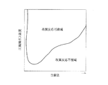
図4は、縦軸を燃料改質気筒内の当量比とし、横軸を燃料改質気筒内の反応ガス温度とした場合における、改質反応可能域、改質反応不能域、および、改質反応可能域内におけるスート(炭素粒子)の生成域を示している。つまり、燃料改質気筒内の当量比および反応ガス温度がスート生成域にある状況では、生成された改質燃料中に比較的多量のスートが存在することになる。 FIG. 4 shows the reforming reaction possible region, the reforming reaction impossible region, and the reforming reaction when the vertical axis is the equivalent ratio in the fuel reforming cylinder and the horizontal axis is the reaction gas temperature in the fuel reforming cylinder. The figure shows a soot (carbon particle) generation region in the reaction possible region. That is, when the equivalence ratio and the reaction gas temperature in the fuel reforming cylinder are in the soot generation region, a relatively large amount of soot is present in the generated reformed fuel.
内燃機関の中負荷運転時や高負荷運転時(燃料改質気筒内の当量比が比較的高い運転域)であって、燃料改質気筒内の当量比および反応ガス温度が図中の点A(改質反応可能域内においてスート生成域から外れた点)にある状態から、機関負荷が低下し、燃料改質気筒内の当量比が1に近づいた場合には、前述した如く、酸化反応量の増大に伴い燃料改質気筒内の反応ガス温度が高くなる(図4における矢印Iを参照)。そして、この際の燃料改質気筒内の当量比および反応ガス温度が点B(スート生成域内の点)の状態となった場合には、生成された改質燃料中に比較的多量のスートが含まれる状況となり、このスートが出力気筒に向けて導出されてしまうことになる。 At the time of medium load operation or high load operation of the internal combustion engine (operating region where the equivalence ratio in the fuel reforming cylinder is relatively high), the equivalence ratio and the reaction gas temperature in the fuel reforming cylinder are point A in the figure. When the engine load is reduced from the state (a point outside the soot generation area in the reformable reaction possible area) and the equivalent ratio in the fuel reforming cylinder approaches 1, as described above, the oxidation reaction amount The reaction gas temperature in the fuel reforming cylinder increases as the pressure increases (see arrow I in FIG. 4). When the equivalence ratio and the reaction gas temperature in the fuel reforming cylinder at this time become point B (point in the soot generation region), a relatively large amount of soot is generated in the generated reformed fuel. In this case, the soot is derived toward the output cylinder.
このようなスートが導出される状況では、出力気筒での改質燃料の燃焼に悪影響を与えたり、この出力気筒内でスートが処理できない場合には、大気中にスートが放出されてしまう可能性がある。 In a situation where such soot is derived, the combustion of reformed fuel in the output cylinder may be adversely affected, or if the soot cannot be processed in the output cylinder, the soot may be released into the atmosphere. There is.
本発明は、かかる点に鑑みてなされたものであり、その目的とするところは、燃料改質気筒および出力気筒を備えた内燃機関に対し、燃料改質気筒でのスートの発生を抑制することが可能な内燃機関の制御装置および内燃機関の制御方法を提供することにある。 The present invention has been made in view of such a point, and an object of the present invention is to suppress generation of soot in a fuel reforming cylinder for an internal combustion engine having a fuel reforming cylinder and an output cylinder. It is an object of the present invention to provide an internal combustion engine control device and an internal combustion engine control method capable of performing the above.
前記の目的を達成するための本発明の解決手段は、燃料改質装置として機能することが可能な燃料改質気筒と、この燃料改質気筒で生成された改質燃料が供給され当該改質燃料の燃焼によって機関出力を得る出力気筒とを備えた内燃機関に適用される制御装置を前提とする。そして、この内燃機関の制御装置は、前記燃料改質気筒が、シリンダと、該シリンダ内に往復動自在に収容されたピストンとを含んで成り、燃料改質時における前記燃料改質気筒内の当量比および反応ガス温度が、この燃料改質気筒内の当量比および反応ガス温度によって規定されるスート生成域を外れた改質反応可能域となるように、前記燃料改質気筒内の当量比に応じて前記燃料改質気筒内の反応ガス温度を調整する反応ガス温度調整部を備えていることを特徴とする。 Means for solving the problems of the present invention for achieving the above object include a fuel reforming cylinder capable of functioning as a fuel reforming device, and a reforming fuel generated by the fuel reforming cylinder being supplied to the fuel reforming cylinder. It is assumed that the control device is applied to an internal combustion engine having an output cylinder that obtains engine output by burning fuel. In the control device for the internal combustion engine, the fuel reforming cylinder includes a cylinder and a piston housed in the cylinder so as to be reciprocally movable . The equivalence ratio in the fuel reforming cylinder is such that the equivalence ratio and the reaction gas temperature are in a reformable reaction region outside the soot generation region defined by the equivalence ratio and the reaction gas temperature in the fuel reforming cylinder. And a reaction gas temperature adjustment unit that adjusts the temperature of the reaction gas in the fuel reforming cylinder according to
この特定事項により、反応ガス温度調整部によって、燃料改質気筒内の当量比に応じた反応ガス温度の調整が行われ、燃料改質気筒内の当量比および反応ガス温度が、スート生成域を外れた改質反応可能域とされることになる。このため、燃料改質気筒でのスートの発生を抑制しながら改質燃料を生成することができる。その結果、スートが原因で出力気筒での改質燃料の燃焼に悪影響を与えたり、大気中にスートが放出されてしまったりすることが抑制される。 According to this specific matter, the reaction gas temperature adjustment unit adjusts the reaction gas temperature according to the equivalent ratio in the fuel reforming cylinder, and the equivalent ratio and the reaction gas temperature in the fuel reforming cylinder change the soot generation area. Thus, the reforming reaction is possible. Therefore, reformed fuel can be generated while suppressing the generation of soot in the fuel reforming cylinder. As a result, it is possible to prevent the soot from adversely affecting the combustion of the reformed fuel in the output cylinder and to prevent the soot from being released into the atmosphere.
また、前記反応ガス温度調整部は、前記燃料改質気筒内の当量比が低下して1に近づいたことに伴う前記燃料改質気筒内の反応ガス温度の上昇を抑制するための制御の制御量を変更するようになっており、前記燃料改質気筒内の当量比が1に近づくほど、前記制御量を大きくするよう構成されていることが好ましい。 Further, the reaction gas temperature adjustment unit controls the control for suppressing the rise of the reaction gas temperature in the fuel reforming cylinder due to the decrease in the equivalence ratio in the fuel reforming cylinder to approach 1. Preferably, the control amount is changed, and the control amount is increased as the equivalent ratio in the fuel reforming cylinder approaches 1.
前述した如く、燃料改質気筒内の当量比が低下して1に近づくほど、燃料改質気筒内での燃料の酸化反応量が多くなり、燃料改質気筒内の反応ガス温度は高くなる。このため、燃料改質時における燃料改質気筒内の当量比および反応ガス温度が、前記スート生成域に入る可能性が高くなる。本解決手段では、燃料改質気筒内の当量比が1に近づくほど前記制御量(燃料改質気筒内の反応ガス温度の上昇を抑制するための制御の制御量)を大きくして、燃料改質気筒内の反応ガス温度の上昇を抑制するようにしている。これにより、燃料改質時における燃料改質気筒内の当量比および反応ガス温度が、スート生成域を外れた改質反応可能域となるようにしている。その結果、燃料改質気筒でのスートの発生を抑制することができる。
As described above, as the equivalent ratio in the fuel reforming cylinder decreases and approaches 1, the amount of fuel oxidation reaction in the fuel reforming cylinder increases, and the temperature of the reaction gas in the fuel reforming cylinder increases. Therefore, there is a high possibility that the equivalence ratio and the reaction gas temperature in the fuel reforming cylinder during the fuel reforming will enter the soot generation region. In this solution, the control amount (control amount for suppressing the rise in the reaction gas temperature in the fuel reforming cylinder) is increased as the equivalence ratio in the fuel reforming
また、前記反応ガス温度調整部は、前記出力気筒から排出された排気ガスの前記燃料改質気筒内への還流量およびこの還流される排気ガスの温度のうち少なくとも一方を調整することによって、前記燃料改質気筒内の反応ガス温度を調整するよう構成されていることが好ましい。 Further, the reaction gas temperature adjustment unit adjusts at least one of a recirculation amount of the exhaust gas discharged from the output cylinder into the fuel reforming cylinder and a temperature of the recirculated exhaust gas, whereby the It is preferable that the temperature of the reaction gas in the fuel reforming cylinder be adjusted.
また、前記反応ガス温度調整部は、前記燃料改質気筒の有効圧縮比を調整することによって、前記燃料改質気筒内の反応ガス温度を調整するよう構成されていてもよい。 Further, the reaction gas temperature adjustment section may be configured to adjust a reaction gas temperature in the fuel reforming cylinder by adjusting an effective compression ratio of the fuel reforming cylinder.
このように、出力気筒から排出された排気ガスの燃料改質気筒内への還流量、この還流される排気ガスの温度、および、燃料改質気筒の有効圧縮比の何れを調整しても燃料改質気筒内の反応ガス温度を調整することが可能である。そして、この燃料改質気筒内の反応ガス温度の調整により、燃料改質時における燃料改質気筒内の当量比および反応ガス温度がスート生成域を外れた改質反応可能域となるようにし、これによって、燃料改質気筒でのスートの発生を抑制することができる。 As described above, even if any of the recirculation amount of the exhaust gas discharged from the output cylinder into the fuel reforming cylinder, the temperature of the recirculated exhaust gas, and the effective compression ratio of the fuel reforming cylinder is adjusted, It is possible to adjust the temperature of the reaction gas in the reforming cylinder. Then, by adjusting the reaction gas temperature in the fuel reforming cylinder, the equivalent ratio and the reaction gas temperature in the fuel reforming cylinder at the time of fuel reforming become a reforming reaction possible region outside the soot generation region, Thus, the generation of soot in the fuel reforming cylinder can be suppressed.
また、前記燃料改質気筒内の反応ガス温度の上昇を抑制するための制御の制御量が制御可能範囲の限界値に達しても、前記燃料改質時における前記燃料改質気筒の当量比および反応ガス温度が前記スート生成域にあると推定された場合には、前記燃料改質気筒での燃料改質運転を非実行とすることが好ましい。 Further, even if the control amount of the control for suppressing the rise of the reaction gas temperature in the fuel reforming cylinder reaches the limit value of the controllable range, the equivalent ratio of the fuel reforming cylinder during the fuel reforming and When it is estimated that the reaction gas temperature is in the soot generation region, it is preferable that the fuel reforming operation in the fuel reforming cylinder is not executed.
これによれば、前記反応ガス温度調整部による制御ではスートの抑制ができないと判断されたことに伴い、燃料改質気筒での燃料改質運転を非実行とすることになる。例えば、燃料改質気筒内への燃料供給を停止する。これにより、スートの発生源である燃料が無くなることで、燃料改質気筒でのスートの発生を防止することができる。 According to this, when it is determined that the soot cannot be suppressed by the control by the reaction gas temperature adjustment unit, the fuel reforming operation in the fuel reforming cylinder is not executed. For example, the supply of fuel into the fuel reforming cylinder is stopped. Thus, the generation of soot in the fuel reforming cylinder can be prevented by eliminating the fuel that is the source of soot.
また、前述した各解決手段に係る内燃機関の制御装置によって実施される内燃機関の制御方法も本発明の技術的思想の範疇である。つまり、燃料改質装置として機能することが可能な燃料改質気筒と、この燃料改質気筒で生成された改質燃料が供給され当該改質燃料の燃焼によって機関出力を得る出力気筒とを備えた内燃機関に適用される制御方法を前提とする。また、前記燃料改質気筒は、シリンダと、該シリンダ内に往復動自在に収容されたピストンとを含んで成っている。そして、この内燃機関の制御方法は、燃料改質時における前記燃料改質気筒内の当量比および反応ガス温度が、この燃料改質気筒内の当量比および反応ガス温度によって規定されるスート生成域を外れた改質反応可能域となるように、前記燃料改質気筒内の当量比に応じて前記燃料改質気筒内の反応ガス温度を調整することを特徴とする。 Further, a control method for an internal combustion engine implemented by the control device for an internal combustion engine according to each of the above-described solving means is also within the scope of the technical idea of the present invention. That is, a fuel reforming cylinder capable of functioning as a fuel reforming apparatus, and an output cylinder to which reformed fuel generated by the fuel reforming cylinder is supplied and which obtains engine output by combustion of the reformed fuel are provided. It is assumed that the control method is applied to an internal combustion engine. The fuel reforming cylinder includes a cylinder and a piston housed in the cylinder so as to be able to reciprocate. The control method for the internal combustion engine includes a soot generation region in which the equivalence ratio and the reaction gas temperature in the fuel reforming cylinder during the fuel reforming are defined by the equivalence ratio and the reaction gas temperature in the fuel reforming cylinder. The reaction gas temperature in the fuel reforming cylinder is adjusted in accordance with the equivalence ratio in the fuel reforming cylinder so that the reforming reaction possible region is out of the range.
この制御方法によっても、前述したように、燃料改質気筒でのスートの発生を抑制しながら改質燃料を生成することができる。その結果、スートが原因で出力気筒での改質燃料の燃焼に悪影響を与えたり、大気中にスートが放出されてしまったりすることが抑制される。
また、前記反応ガス温度は、前記ピストンが圧縮上死点に達した時点での前記燃料改質気筒内のガス温度である。
According to this control method, as described above, reformed fuel can be generated while suppressing generation of soot in the fuel reforming cylinder. As a result, it is possible to prevent the soot from adversely affecting the combustion of the reformed fuel in the output cylinder and to prevent the soot from being released into the atmosphere.
Further, the reaction gas temperature is a gas temperature in the fuel reforming cylinder when the piston reaches a compression top dead center.
本発明では、燃料改質時における燃料改質気筒内の当量比および反応ガス温度がスート生成域を外れた改質反応可能域となるように、燃料改質気筒内の当量比に応じて燃料改質気筒内の反応ガス温度を調整するようにしている。このため、燃料改質気筒でのスートの発生を抑制しながら改質燃料を生成することができる。その結果、スートが原因で出力気筒での改質燃料の燃焼に悪影響を与えたり、大気中にスートが放出されてしまったりすることを抑制できる。 In the present invention, the fuel is changed in accordance with the equivalence ratio in the fuel reforming cylinder so that the equivalence ratio in the fuel reforming cylinder and the reaction gas temperature in the reforming reaction possible region outside the soot generation region during fuel reforming. The reaction gas temperature in the reforming cylinder is adjusted. Therefore, reformed fuel can be generated while suppressing the generation of soot in the fuel reforming cylinder. As a result, it is possible to suppress that the soot adversely affects the combustion of the reformed fuel in the output cylinder and that the soot is released into the atmosphere.
以下、本発明の実施の形態を図面に基づいて説明する。本実施形態では、船舶用の内燃機関に本発明を適用した場合について説明する。 Hereinafter, embodiments of the present invention will be described with reference to the drawings. In the present embodiment, a case where the present invention is applied to an internal combustion engine for a ship will be described.
−内燃機関のシステム構成−
図1は本実施形態に係る内燃機関のシステム構成を示す図である。
-System configuration of internal combustion engine-
FIG. 1 is a diagram showing a system configuration of the internal combustion engine according to the present embodiment.
この図1に示すように、本実施形態に係る内燃機関1は、燃料改質気筒2および出力気筒3を備えている。また、この内燃機関1は、前記燃料改質気筒2や前記出力気筒3に対し、ガスの供給(導入)またはガスの排出(導出)を行うための配管系として、吸気系4、改質燃料供給系5、排気系6、EGR系7、および、出力気筒バイパス系8を備えている。
As shown in FIG. 1, the
(燃料改質気筒および出力気筒)
燃料改質気筒2および出力気筒3は、共にレシプロ型で構成されている。具体的に、各気筒2,3は、シリンダブロック(図示省略)に形成されたシリンダボア21,31内にピストン22,32が往復動自在に収容されて構成されている。燃料改質気筒2では、シリンダボア21、ピストン22、図示しないシリンダヘッドによって燃料改質室23が形成されている。出力気筒3では、シリンダボア31、ピストン32、図示しないシリンダヘッドによって燃焼室33が形成されている。
(Fuel reforming cylinder and output cylinder)
Both the
本実施形態に係る内燃機関1は、シリンダブロックに4つの気筒が備えられ、そのうちの1つの気筒が燃料改質気筒2として構成されており、他の3つの気筒が出力気筒3として構成されている。そして、燃料改質気筒2で生成された改質燃料が各出力気筒3それぞれに供給される構成となっている。各気筒2,3の数はこれに限定されるものではない。例えば、シリンダブロックに6つの気筒が備えられ、そのうちの2つの気筒が燃料改質気筒2として構成されており、他の4つの気筒が出力気筒3として構成されていてもよい。
In the
各気筒2,3のピストン22,32はそれぞれコネクティングロッド24,34を介してクランクシャフト11に連結されている。これにより、ピストン22,32の往復運動とクランクシャフト11の回転運動との間で運動が変換されるようになっている。クランクシャフト11は、クラッチ機構(図示省略)を介して船舶のスクリュー軸に連結可能となっている。燃料改質気筒2のピストン22と出力気筒3のピストン32とは前記コネクティングロッド24,34およびクランクシャフト11を介して互いに連結されている。このため、これら気筒2,3間での動力伝達や、これら気筒2,3から出力された動力のスクリュー軸への伝達等が可能となっている。
The
燃料改質気筒2には、燃料改質室23に改質前の燃料として例えば軽油等の燃料を供給するインジェクタ25が備えられている。この燃料改質室23では、インジェクタ25から燃料が供給されることにより、当量比の高い混合気が断熱圧縮される。これにより、高温高圧の環境下で燃料が改質し、水素、一酸化炭素、メタン等のアンチノック性の高い改質燃料が生成される。
The
出力気筒3には、燃焼室33に例えば軽油等の燃料を供給するインジェクタ35が備えられている。この燃焼室33では、前記燃料改質気筒2で生成された改質燃料が空気と共に供給され、この燃焼室33で希薄混合気の希薄予混合燃焼が行われる。これにより、ピストン32の往復動に伴ってクランクシャフト11が回転し、機関出力が得られる。
The
(吸気系)
吸気系4は、燃料改質気筒2の燃料改質室23および出力気筒3の燃焼室33それぞれに空気(新気)を導入するものである。
(Intake system)
The intake system 4 introduces air (fresh air) into each of the
この吸気系4は、メイン吸気通路41、このメイン吸気通路41が2系統に分岐されて成る燃料改質気筒吸気通路42および出力気筒吸気通路43を備えている。メイン吸気通路41には、ターボチャージャ12のコンプレッサホイール12aが備えられている。燃料改質気筒吸気通路42は燃料改質気筒2の吸気ポートに連通している。この吸気ポートと燃料改質気筒2の燃料改質室23との間には吸気バルブ26が開閉可能に配設されている。また、この燃料改質気筒吸気通路42には開度調整可能な吸気量調整弁45が備えられている。出力気筒吸気通路43は出力気筒3の吸気ポートに連通している。この吸気ポートと出力気筒3の燃焼室33との間には吸気バルブ36が開閉可能に配設されている。また、この出力気筒吸気通路43には吸気冷却器(インタクーラ)44が備えられている。
The intake system 4 includes a
(改質燃料供給系)
改質燃料供給系5は、前記燃料改質気筒2で生成された改質燃料を出力気筒3の燃焼室33に向けて供給するものである。
(Reformed fuel supply system)
The reformed
この改質燃料供給系5は改質燃料供給通路51を備えている。この改質燃料供給通路51には改質燃料冷却器52が備えられている。改質燃料供給通路51の上流端は燃料改質気筒2の排気ポートに連通している。この排気ポートと燃料改質気筒2の燃料改質室23との間には排気バルブ27が開閉可能に配設されている。また、改質燃料供給通路51の下流端は出力気筒吸気通路43に連通している。この改質燃料供給通路51と出力気筒吸気通路43との連通部分にはミキサ53が設けられている。このため、燃料改質気筒2で生成された改質燃料は、このミキサ53において、出力気筒吸気通路43を流れる空気と混合されて出力気筒3の燃焼室33に供給されることになる。
The reformed
(排気系)
排気系6は、前記出力気筒3で発生した排気ガスを排出するものである。この排気系6は排気通路61を備えている。この排気通路61には、ターボチャージャ12のタービンホイール12bが備えられている。排気通路61は出力気筒3の排気ポートに連通している。この排気ポートと出力気筒3の燃焼室33との間には排気バルブ37が開閉可能に配設されている。
(Exhaust system)
The exhaust system 6 is for exhausting exhaust gas generated in the
(EGR系)
EGR系7は、燃料改質気筒EGR系7Aと出力気筒EGR系7Bとを備えている。
(EGR system)
The
燃料改質気筒EGR系7Aは、前記排気通路61を流れる排気ガスの一部を燃料改質気筒2の燃料改質室23に向けて供給するものである。この燃料改質気筒EGR系7Aは燃料改質気筒EGR通路71を備えている。この燃料改質気筒EGR通路71は、上流端が排気通路61に、下流端が燃料改質気筒吸気通路42における吸気量調整弁45の下流側にそれぞれ連通されている。燃料改質気筒EGR通路71にはEGRガス冷却器72が備えられている。また、燃料改質気筒EGR通路71におけるEGRガス冷却器72よりも下流側(燃料改質気筒吸気通路42側)にはEGRガス量調整弁73が備えられている。また、この燃料改質気筒EGR系7Aには、EGRガス冷却器72をバイパスしてEGRガスを流すためのクーラバイパス通路74が設けられている。このクーラバイパス通路74にはバイパス量調整弁75が備えられている。
The fuel reforming
一方、出力気筒EGR系7Bは、前記排気通路61を流れる排気ガスの一部を出力気筒3の燃焼室33に戻すものである。この出力気筒EGR系7Bは出力気筒EGR通路76を備えている。この出力気筒EGR通路76は、上流端が排気通路61に、下流端が出力気筒吸気通路43におけるミキサ53の下流側にそれぞれ連通されている。出力気筒EGR通路76にはEGRガス冷却器77が備えられている。また、出力気筒EGR通路76におけるEGRガス冷却器77よりも下流側(出力気筒吸気通路43側)にはEGRガス量調整弁78が備えられている。
On the other hand, the output
(出力気筒バイパス系)
出力気筒バイパス系8は、前記燃料改質気筒2から排出されたガスを出力気筒3に供給することなく(出力気筒3をバイパスさせて)、前記排気通路61に導入するためのものである。この出力気筒バイパス系8は出力気筒バイパス通路81を備えている。この出力気筒バイパス通路81は、上流端が改質燃料供給通路51における改質燃料冷却器52の上流側に、下流端が出力気筒EGR通路76におけるEGRガス冷却器77の上流側(排気通路61側)にそれぞれ連通されている。また、この出力気筒バイパス通路81にはバイパス量調整弁82が備えられている。
(Output cylinder bypass system)
The output cylinder bypass system 8 is for introducing the gas discharged from the
なお、前述した各系に備えられている冷却器44,52,72,77は、ガスを冷却するための冷熱源として、エンジン冷却水または海水等が使用される。また、これら冷却器44,52,72,77は空冷式のものであってもよい。
The
−内燃機関の制御系−
図2は、内燃機関1の制御系の概略構成を示す図である。内燃機関1には、この内燃機関1に備えられた各種アクチュエータを制御するための制御装置に相当するECU(Electronic Control Unit)100が備えられている。このECU100は、CPU(Central Processing Unit)、ROM(Read Only Memory)、RAM(Random Access Memory)およびバックアップRAM等を備えている。
−Control system of internal combustion engine−
FIG. 2 is a diagram illustrating a schematic configuration of a control system of the
ROMには、各種制御プログラムや、それら各種制御プログラムを実行する際に参照されるマップ等が記憶されている。CPUは、ROMに記憶された各種制御プログラムやマップに基づいて演算処理を実行する。また、RAMはCPUでの演算結果や各センサから入力されたデータ等を一時的に記憶するメモリである。また、バックアップRAMはシステム停止時等において保存すべきデータ等を記憶する不揮発性のメモリである。 The ROM stores various control programs, maps referred to when the various control programs are executed, and the like. The CPU executes arithmetic processing based on various control programs and maps stored in the ROM. The RAM is a memory for temporarily storing a result of calculation by the CPU, data input from each sensor, and the like. The backup RAM is a non-volatile memory for storing data to be stored when the system is stopped.
図2に示すように、内燃機関1には、吸気流量センサ101、吸入ガス圧力センサ102、吸入ガス温度センサ103、吸入ガスO2センサ104、排気圧力センサ105、水温センサ106等が備えられている。
As shown in FIG. 2, the
吸気流量センサ101は、前記メイン吸気通路41を流れる吸気(空気)の流量に応じた出力信号をECU100に送信する。
The intake
吸入ガス圧力センサ102は、燃料改質気筒吸気通路42を流れる吸入ガスの圧力に応じた出力信号をECU100に送信する。具体的には、燃料改質気筒吸気通路42に対する燃料改質気筒EGR通路71の連通部分よりも下流側の吸入ガス圧力に応じた出力信号をECU100に送信する。
The intake
吸入ガス温度センサ103は、燃料改質気筒吸気通路42を流れる吸入ガスの温度に応じた出力信号をECU100に送信する。具体的には、燃料改質気筒吸気通路42に対する燃料改質気筒EGR通路71の連通部分よりも下流側の吸入ガス温度に応じた出力信号をECU100に送信する。
The intake gas temperature sensor 103 transmits to the
吸入ガスO2センサ104は、燃料改質気筒吸気通路42を流れる吸入ガス中の酸素濃度に応じた出力信号をECU100に送信する。具体的には、燃料改質気筒吸気通路42に対する燃料改質気筒EGR通路71の連通部分よりも下流側の吸入ガス中酸素濃度に応じた出力信号をECU100に送信する。
The intake gas O 2 sensor 104 transmits an output signal corresponding to the oxygen concentration in the intake gas flowing through the fuel reforming
排気圧力センサ105は、前記排気通路61を流れる排気の圧力に応じた出力信号をECU100に送信する。具体的には、排気通路61に対する燃料改質気筒EGR通路71の連通部分よりも上流側の排気圧力に応じた出力信号をECU100に送信する。
The
水温センサ106は、シリンダブロックに形成された冷却水通路13内を流れる冷却水の温度に応じた出力信号をECU100に送信する。具体的には、燃料改質気筒2の周囲に形成されている冷却水通路13内を流れる冷却水の温度に応じた出力信号をECU100に送信する。
また、ECU100には、前記各インジェクタ25,35、各調整弁45,73,75,78,82等が電気的に接続されている。また、燃料改質気筒2の吸気バルブ26および排気バルブ27それぞれには可変動弁装置28,29が備えられており、各バルブ26,27の開閉タイミングを調整することが可能となっている。ECU100は、この可変動弁装置28,29にも電気的に接続されている。ECU100は、前記した各種センサ101〜106の出力信号等に基づいて、前記各インジェクタ25,35の燃料噴射制御(インジェクタ25,35の開閉制御)、各調整弁45,73,75,78,82の開閉制御(ガス流量制御)、および、可変動弁装置28,29による各バルブ26,27の開閉タイミング制御を行う。
Further, the
−内燃機関の基本動作−
次に、前述の如く構成された内燃機関1の基本動作について説明する。
−Basic operation of internal combustion engine−
Next, the basic operation of the
内燃機関1の暖機が完了している状態(燃料改質室23での燃料の改質反応が可能となっている状態)での基本動作として、メイン吸気通路41に導入される空気は、ターボチャージャ12のコンプレッサホイール12aによって加圧される。そして、この空気は、燃料改質気筒吸気通路42および出力気筒吸気通路43に分流される。この際、燃料改質気筒吸気通路42を流れる吸気の流量は吸気量調整弁45によって調整される。また、燃料改質気筒吸気通路42には、燃料改質気筒EGR系7Aを流れたEGRガスが導入される。この際、燃料改質気筒吸気通路42に導入されるEGRガス量はEGRガス量調整弁73によって調整される。また、燃料改質気筒吸気通路42に導入されるEGRガスの温度はバイパス量調整弁75の開度に応じてEGRガス冷却器72をバイパスするEGRガス量によって調整される。これにより、燃料改質気筒2の燃料改質室23には、空気およびEGRガスが導入されることになる。この際、吸気量調整弁45の開度によって調整される吸気の流量、EGRガス量調整弁73の開度によって調整されるEGRガスの流量、および、バイパス量調整弁75の開度によって調整されるEGRガスの温度は、燃料改質室23での当量比を高く設定し、また、燃料の改質を良好に行うことができる燃料改質室23のガス温度が確保できるように調整される。具体的には、吸気量調整弁45、EGRガス量調整弁73およびバイパス量調整弁75の開度は、後述するようにインジェクタ25から燃料改質室23に燃料が供給された際における燃料改質室23での当量比を例えば2.5以上(好ましくは4.0以上)に設定し、且つ燃料改質室23のガス温度が改質反応可能温度の下限値以上の値となるように、予め実験やシミュレーションに基づいて作成された開度設定マップに従って設定される。
As a basic operation in a state where the
このようにして燃料改質気筒2の燃料改質室23に、空気およびEGRガスが導入された状態で、インジェクタ25から燃料改質室23に燃料が供給される。このインジェクタ25からの燃料供給量は、基本的には機関要求出力に応じて設定される。具体的には、インジェクタ25に供給されている燃料圧力に応じ、目標とする燃料供給量が得られるように、インジェクタ25の開弁期間が設定される。また、この際のインジェクタ25の開弁タイミングは、燃料改質気筒2の吸気行程が終了するまでの間に前記目標とする燃料供給量の噴射が完了するように設定されることが望ましいが、ピストン22が圧縮上死点付近に到達する前に混合気が均一に混合可能である場合には、圧縮行程途中まで燃料噴射期間が継続されてもよい。これにより、ピストン22が圧縮上死点に達するまでに、燃料改質室23において均質な混合気(当量比の高い混合気)が生成されることになる。
In this way, the fuel is supplied from the
ピストン22が圧縮上死点に向かって移動する間に、燃料改質室23の圧力および温度が上昇し、この燃料改質室23では、当量比の高い混合気(例えば4.0以上の当量比の混合気)が断熱圧縮される。これにより、高温高圧の環境下で、燃料の脱水素反応、部分酸化反応、水蒸気改質反応、熱解離反応が行われて、燃料が改質され、水素、一酸化炭素、メタン等のアンチノック性の高い改質燃料が生成される。
During the movement of the
燃料改質室23から排出された改質燃料は、改質燃料供給通路51を流れる際に改質燃料冷却器52において冷却される。この冷却により、出力気筒吸気通路43や燃焼室33での改質燃料の過早着火が抑制される。そして、この冷却された改質燃料は、ミキサ53において、出力気筒吸気通路43を流れる空気と混合され、出力気筒3の燃焼室33に供給される。また、必要に応じて、EGRガス量調整弁78が開放され、出力気筒EGR通路76を経てEGRガスが出力気筒3の燃焼室33に導入される。
The reformed fuel discharged from the
このようにして、出力気筒3の燃焼室33には、空気、改質燃料、EGRガスがそれぞれ導入され、この燃焼室33内の当量比が0.1〜0.8程度に調整される。
In this way, air, reformed fuel, and EGR gas are introduced into the
出力気筒3では、圧縮行程において、希薄混合ガスの断熱圧縮が行われ、ピストン32が圧縮上死点に達した時点で、インジェクタ35から微量の燃料噴射が行われる。これにより、燃焼室33内の混合気が着火し、希薄予混合燃焼が行われる。なお、インジェクタ35からの燃料噴射を行わなくても燃焼室33の混合気が自着火(予混合圧縮自着火)する場合には、このインジェクタ35からの燃料噴射は必ずしも必要ない。
In the
前記燃焼によって、ピストン32が往復動し、クランクシャフト11が回転することで機関出力が得られる。この機関出力は前記スクリュー軸に伝達される。また、この機関出力の一部は、燃料改質気筒2におけるピストン22の往復動の駆動源として使用される。
Due to the combustion, the
また、この内燃機関1の冷間始動時には、図示しないスタータによってクランクシャフト11が回転(クランキング)され、燃料改質気筒2および出力気筒3それぞれのインジェクタ25,35から所定量の燃料噴射が行われる。この際の燃料噴射は、燃料改質室23および燃焼室33それぞれにおける当量比が1未満の値となるように設定される。これにより、燃料改質気筒2の燃料改質室23および出力気筒3の燃焼室33では、それぞれ圧縮着火燃焼が行われる。そして、燃料改質気筒2の暖機が進み、改質反応が可能な温度に達すると、前述した改質燃料の生成動作(燃料改質運転)に切り替えられることになる。このように、燃料改質気筒2は、出力気筒3と同様に機関出力を得るための気筒として機能することが可能であり、また、前述したように燃料改質装置として機能することが可能となっている。
During a cold start of the
なお、内燃機関1の緊急停止時等であって、出力気筒3への改質燃料の供給を停止させる際には、バイパス量調整弁82が開放される。これにより、改質燃料は、出力気筒バイパス通路81を経て排気通路61に導入されることになり、出力気筒3への改質燃料の供給は停止される。
When the supply of the reformed fuel to the
この内燃機関1によれば、出力気筒3内において希薄混合気の燃焼(均一希薄燃焼)が行われるため、NOx排出量の低減を図ることができる。これにより、排気ガスを浄化するための後処理装置を不要またはその容量を大幅に小型化することが可能である。また、アンチノック性の高い燃料の燃焼が行われるため、ノッキングが抑制されると共にディーゼルマイクロパイロット着火により最適な時期での燃焼が実現できることから、燃焼効率の向上を図ることもできる。
According to the
−改質反応可能域−
次に、燃料改質気筒2の燃料改質室23において改質反応を可能にするための条件について説明する。この改質反応を可能にするためには、燃料改質室23における混合気の当量比および燃料改質室23の温度(ガス温度)が共に、改質反応を可能にする範囲内にあることが必要である。また、燃料改質室23における混合気の当量比に応じて、燃料が改質反応を行うのに必要なガス温度は異なっており、改質反応を可能にするためには、混合気の当量比に応じた燃料改質室23の温度(改質反応を可能にする最低温度以上の温度)が必要となる。
-Reformable reaction area-
Next, conditions for enabling a reforming reaction in the
図3は、燃料改質室23における混合気の当量比(横軸)、および、燃料改質気筒2においてピストン22が圧縮上死点に達した時点での燃料改質室23内のガス温度(以下、圧縮端ガス温度という;縦軸)と、改質反応可能域との関係を示す図である。この図3に示すように、燃料改質室23において改質反応を可能にするためには、燃料改質室23における混合気の当量比として所定値以上(例えば2以上)の当量比が必要であり、且つその当量比が高いほど、改質反応を行うために必要な圧縮端ガス温度は高くなっている。つまり、燃料改質室23において改質反応を行うためには、燃料改質室23における混合気の当量比が高いほど、圧縮端ガス温度を高くする必要がある。
FIG. 3 shows the equivalence ratio of the air-fuel mixture in the fuel reforming chamber 23 (horizontal axis), and the gas temperature in the
−燃料改質運転の制御−
次に、本実施形態の特徴である燃料改質運転の制御について説明する。前述したように、燃料改質気筒2において改質燃料を生成する場合、燃料改質室23内の当量比を高くして、酸化反応(燃焼)を抑制しながら改質反応が行われるようにしている。また、燃料改質室23に供給される燃料の量は、機関負荷に応じて変更される。つまり、内燃機関1の低負荷運転時には、燃料改質室23に供給される燃料の量は少なくなる。このように燃料改質室23への燃料供給量が少なくなった場合、この燃料改質室23内の当量比が(低下して)1に近づく可能性がある。このような状況では、燃料改質室23内での燃料の酸化反応量(燃焼量)が多くなり、発生熱量が多くなって燃料改質室23内の温度(反応ガス温度)が高くなってしまう。
-Control of fuel reforming operation-
Next, control of the fuel reforming operation, which is a feature of the present embodiment, will be described. As described above, when generating the reformed fuel in the
図4を用いて前述したように、内燃機関1の中負荷運転時や高負荷運転時であって、燃料改質室23内の当量比および反応ガス温度が図中の点Aにある状態から、機関負荷が低下し、燃料改質室23内の当量比が1に近づいた場合には、酸化反応量の増大に伴い燃料改質室23内の反応ガス温度が高くなる(図4における矢印Iを参照)。そして、この際の燃料改質室23内の当量比および反応ガス温度が点B(スート生成域内の点)の状態となった場合には、生成された改質燃料中に比較的多量のスートが含まれる状況となり、このスートが出力気筒3に向けて導出されてしまうことになる。このようなスートが導出される状況では、燃焼室33での改質燃料の燃焼に悪影響を与えたり、燃焼室33内でスートが処理できない場合には、大気中にスートが放出されてしまう可能性がある。
As described above with reference to FIG. 4, when the
本実施形態は、この点に鑑み、燃料改質時における燃料改質室23内の当量比および反応ガス温度が、この燃料改質室23内の当量比および反応ガス温度によって規定されるスート生成域を外れた改質反応可能域となるように、燃料改質室23内の当量比に応じて燃料改質室23内の反応ガス温度を調整するようにしている。
In view of this point, in the present embodiment, the equivalence ratio and the reaction gas temperature in the
具体的には、燃料改質室23内における混合気の当量比に応じてスート発生下限温度を設定しておく。このスート発生下限温度は、混合気の当量比毎に設定されるものであって、その当量比においてスートが発生する反応ガス温度の下限値である。
Specifically, the soot generation lower limit temperature is set according to the equivalent ratio of the air-fuel mixture in the
そして、燃料改質気筒2においてピストン22が圧縮上死点に達する時点における燃料改質室23のガス温度(圧縮端ガス温度)が、前記スート発生下限温度以上になると推定された場合、つまり、改質反応時における反応ガス温度(前記圧縮端ガス温度に相当)が、現在の当量比にあってはスート生成域に入ると推定された場合には、この燃料改質室23の反応ガス温度の上昇(前述した、燃料改質室23内の当量比が1に近づいたことに起因する反応ガス温度の上昇)を抑制するための反応ガス温度調整動作を実行し、これによって、燃料改質時における燃料改質室23内の当量比および反応ガス温度が、スート生成域を外れた改質反応可能域となるようにしている。以下、具体的に説明する。
When the gas temperature (compression end gas temperature) of the
本実施形態における燃料改質運転の制御では、推定される実際の圧縮端ガス温度と、前記スート発生下限温度とを比較する。 In the control of the fuel reforming operation in the present embodiment, the estimated actual compression end gas temperature is compared with the soot generation lower limit temperature.
そして、実際の圧縮端ガス温度がスート発生下限温度未満であると推定された場合には、そのサイクル(または次回のサイクル)において、燃料改質気筒2での燃料改質運転を実行する(反応ガス温度調整動作を実行することなく、燃料改質運転を実行する)。つまり、インジェクタ25から燃料改質室23への燃料の供給(前記改質反応を行うべく燃料改質室23内の当量比を高く設定する燃料の供給)を実行する。
Then, when it is estimated that the actual compression end gas temperature is lower than the soot generation lower limit temperature, the
一方、実際の圧縮端ガス温度がスート発生下限温度以上であると推定された場合には、そのサイクル(または次回のサイクル)において、燃料改質気筒2での燃料改質運転を実行しながらも、燃料改質室23の反応ガス温度の上昇を抑制するための反応ガス温度調整動作を実行する。
On the other hand, when it is estimated that the actual compression end gas temperature is equal to or higher than the soot generation lower limit temperature, the
以下、実際の圧縮端ガス温度の算出動作(推定動作)、スート発生下限温度(当量比に応じて設定されたスート発生下限温度)の設定動作、および、これら実際の圧縮端ガス温度およびスート発生下限温度を利用した燃料改質運転の制御について順に説明する。 Hereinafter, the operation of calculating the actual compression end gas temperature (estimation operation), the operation of setting the soot generation lower limit temperature (the soot generation lower limit temperature set according to the equivalence ratio), and the actual compression end gas temperature and soot generation The control of the fuel reforming operation using the lower limit temperature will be described in order.
(圧縮端ガス温度の算出動作)
先ず、実際の圧縮端ガス温度の算出動作(推定動作)について説明する。
(Calculation operation of compression end gas temperature)
First, the calculation operation (estimation operation) of the actual compression end gas temperature will be described.
燃料改質室23での実際の圧縮端ガス温度は以下の式(1)によって算出(推定)することが可能である。
The actual compression end gas temperature in the

この式(1)において、TTDCは圧縮端ガス温度であり、Tiniは圧縮前のガス温度すなわち吸入ガス温度であり、εは燃料改質気筒2の有効圧縮比であり、κは燃料改質室23内の吸入ガスのポリトロープ数であり、Creactは燃料改質室23での改質反応(特に部分酸化反応)に伴う温度上昇分(ピストン22が圧縮上死点に達した時点での改質反応による温度上昇分)を考慮した補正係数である。
In this equation (1), T TDC is a compression end gas temperature, T ini is a gas temperature before compression, that is, a suction gas temperature, ε is an effective compression ratio of the
以下、式(1)における各パラメータの算出について説明する。 Hereinafter, calculation of each parameter in equation (1) will be described.
(吸入ガス温度Tini)
吸入ガス温度Tiniは前記吸入ガス温度センサ103からの出力信号に基づいて算出される。ここで算出される吸入ガス温度Tiniは、燃料改質気筒吸気通路42に対する燃料改質気筒EGR通路71の連通部分よりも下流側の吸入ガス温度である。
(Suction gas temperature T ini )
The intake gas temperature Tini is calculated based on an output signal from the intake gas temperature sensor 103. The intake gas temperature T ini calculated here is the intake gas temperature downstream of the portion where the fuel reforming
また、吸入ガス温度Tiniとしては、燃料改質気筒吸気通路42を流れる吸入ガスの温度に代えて、燃料改質気筒2の吸気ポートを流れる吸入ガスの温度を採用するようにしてもよい。または、ピストン22が吸入下死点に達した時点での燃料改質室23内のガス温度や、吸気バルブ26が閉弁した時点での燃料改質室23内のガス温度を検出または推定し、これを吸入ガス温度Tiniとして採用するようにしてもよい。
Further, as the intake gas temperature T ini , the temperature of the intake gas flowing through the intake port of the
(燃料改質気筒の有効圧縮比ε)
燃料改質気筒2の有効圧縮比εは、燃料改質気筒2における吸気バルブ26が閉弁した時点での燃料改質室23の容積と、ピストン22が圧縮上死点に達した時点での燃料改質室23の容積との比として算出される。なお、この燃料改質気筒2の有効圧縮比εは、ピストン22が下死点にある時点での燃料改質室23の容積とピストン22が上死点にある時点での燃料改質室23の容積との比(見かけの圧縮比)によって簡易的に求めるようにしてもよい。
(Effective compression ratio ε of fuel reforming cylinder)
The effective compression ratio ε of the
(ポリトロープ数κ)
ポリトロープ数κは、燃料改質室23内でのガスの圧縮行程における定圧比熱と定積比熱との比で定義される。吸入ガスの全量が空気であり、シリンダ壁面への熱流出が無い場合にはκ=1.4程度となる。しかしながら、燃料改質室23における吸入ガスの実際のポリトロープ数は、全量が空気である場合や熱流出が無い場合とは異なっているので、以下のような修正が行われる。
(Number of polytropes κ)
The polytrope number κ is defined by the ratio between the specific heat at a constant pressure and the specific heat at a constant volume in the gas compression process in the
以下に述べる冷却水温度に応じたポリトロープ数の修正、ガス組成に応じたポリトロープ数の修正および当量比に応じたポリトロープ数の修正は、何れか一つを行って前記式(1)のポリトロープ数κに適用するようにしてもよいし、2つ以上を組み合わせて修正を行って前記式(1)のポリトロープ数κに適用するようにしてもよい。 The correction of the number of polytropes in accordance with the cooling water temperature, the correction of the number of polytropes in accordance with the gas composition, and the correction of the number of polytropes in accordance with the equivalence ratio, which will be described below, are performed by any one of the following methods. It may be applied to κ, or may be modified by combining two or more and applied to the polytrope number κ in the above equation (1).
・冷却水温度に応じたポリトロープ数の修正
前記ポリトロープ数κは熱損失量に応じて変化する。前述したようにシリンダブロックには冷却水通路13が形成されており、この冷却水通路13を流れる冷却水に向けての熱流出が存在している。このため、前記水温センサ106からの出力に基づいて冷却水の温度を算出することで、熱損失量を予測することが可能である。または、冷却水温度と熱損失量との関係を予め把握しておくことで、この冷却水温度から熱損失量を推定することが可能である。
-Correction of the number of polytropes according to the cooling water temperature The number of polytropes κ changes according to the amount of heat loss. As described above, the cooling
図5は、この冷却水温度に応じた修正ポリトロープ数の演算ロジックを示すブロック図である。この図5に示すように、水温センサ106からの出力に基づいて算出された冷却水の温度から、ポリトロープ数の低下量Δκを求め、これを空気のポリトロープ数から減算することによって、冷却水温度に応じた(熱損失量に応じた)修正ポリトロープ数を求めることができる。
FIG. 5 is a block diagram showing the calculation logic of the number of corrected polytropes according to the cooling water temperature. As shown in FIG. 5, the amount of decrease in the number of polytropes Δκ is obtained from the temperature of the cooling water calculated based on the output from the
・ガス組成に応じたポリトロープ数の修正
燃料改質室23内のガス組成によってもポリトロープ数κは変化する。つまり、吸入ガスの全量が空気である場合、吸入ガスの大部分は2原子分子であるため、ポリトロープ数κは「1.4」程度となる。これに対し、吸入ガス中に既燃ガス(CO2やH2O)や燃料が含まれていると、前記2原子分子の割合が低下することで、ポリトロープ数κも低下することになる。
Correction of Number of Polytropes According to Gas Composition The number of polytropes κ also changes according to the gas composition in the
このため、前記吸入ガスO2センサ104からの出力信号に基づき、吸入ガス中の酸素のモル分率を基に、吸入ガス中の二酸化炭素のモル分率を計算し、各ガス成分のモル分率に基づいてポリトロープ数を推定する。 For this reason, the mole fraction of carbon dioxide in the suction gas is calculated based on the mole fraction of oxygen in the suction gas based on the output signal from the suction gas O 2 sensor 104, and the mole fraction of each gas component is calculated. Estimate the number of polytropes based on the rate.
例えば、先ず、以下の式(2)によって吸入ガスの定圧モル比熱を求める。 For example, first, the constant pressure molar specific heat of the suction gas is obtained by the following equation (2).
この式(2)において、Cp_intakeは吸入ガスの定圧モル比熱であり、Ψiは各ガス成分それぞれのモル分率であり、Cp_iは各ガス成分それぞれの定圧モル比熱である。各ガス成分それぞれのモル分率Ψi、各ガス成分それぞれの定圧モル比熱Cp_iは、燃料の種類および燃料改質室23内の当量比(現在の当量比)等に応じて決定されるものであり、実験やシミュレーションに基づいて作成されたマップ(前記ROMに記憶されたマップ)に従って求めることが可能である。 In the formula (2), C p_intake is constant pressure molar specific heat of intake gas, [psi i is the mole fraction of each of the gas components, C p_i is a constant pressure molar specific heat of each of the gas components. The molar fraction i i of each gas component and the constant-pressure molar specific heat C p — i of each gas component are determined according to the type of fuel, the equivalence ratio in the fuel reforming chamber 23 (current equivalence ratio), and the like. It can be obtained according to a map created based on experiments and simulations (maps stored in the ROM).
これにより、以下の式(3)によって、吸入ガスのポリトロープ数κを算出することができる。 Thereby, the polytrope number κ of the suction gas can be calculated by the following equation (3).
このようにしてガス組成に応じた修正ポリトロープ数を求めることができる。 Thus, the number of modified polytropes according to the gas composition can be obtained.
・当量比に応じたポリトロープ数の修正
また、燃料改質室23内の当量比を推定し、この当量比からポリトロープ数κを補正演算することも可能である。
-Correction of the number of polytropes according to the equivalence ratio It is also possible to estimate the equivalence ratio in the
図6は、この当量比に応じた修正ポリトロープ数の演算ロジックを示すブロック図である。この図6に示すように、当量比から、ポリトロープ数の低下量Δκを求め、これを空気のポリトロープ数から減算することによって、当量比に応じた修正ポリトロープ数を求めることができる。 FIG. 6 is a block diagram showing a logic for calculating the number of corrected polytropes according to the equivalent ratio. As shown in FIG. 6, the amount of decrease Δκ in the number of polytropes is determined from the equivalent ratio, and this is subtracted from the number of air polytropes, whereby the number of corrected polytropes according to the equivalent ratio can be determined.
この場合における当量比の算出手法としては、前記吸気流量センサ101からの出力信号に基づいて吸気の流量を算出する。また、吸入ガス圧力センサ102からの出力信号に基づいて算出された吸入ガスの圧力と、排気圧力センサ105からの出力信号に基づいて算出された排気の圧力との差からEGRガス量(燃料改質気筒2に導入されるEGRガス量)を算出する。そして、前記吸気の流量、前記EGRガス量、燃料改質室23への燃料供給量(インジェクタ25に対する噴射指令値から求められる燃料供給量)から当量比を算出する。また、EGRガス量を考慮しない場合には、吸気流量センサ101からの出力信号に基づいて算出された吸気の流量と、燃料改質室23への燃料供給量との比から当量比を算出するようにしてもよい。
As a method of calculating the equivalence ratio in this case, the flow rate of intake air is calculated based on an output signal from the intake
(改質反応に伴う温度上昇分の補正係数Creact)
改質反応に伴う温度上昇分の補正係数Creactは、ピストン22が圧縮上死点に達する前に改質反応が開始された場合、部分酸化反応によるガス温度の上昇分だけ圧縮端ガス温度を補正するためのものである。このため、前述したように、燃料改質室23内の当量比が1に近づいた場合には、燃料改質室23内の酸化反応量の増大に伴い、この補正係数Creactは大きな値として求められることになる。つまり、この補正係数Creactは、図4における矢印の傾き(当量比の変化に対する反応ガス温度の変化の割合)を表す値となる。
(Correction coefficient Creact of temperature rise due to reforming reaction)
When the reforming reaction is started before the
この補正係数Creactは、燃料改質室23内の温度(反応場の温度)、燃料改質室23内の酸素濃度、燃料改質室23内の燃料濃度等をパラメータとして算出することができる。また、この補正係数Creactは、運転条件に対する改質反応の開始時期や部分酸化反応による発熱量を実験等によって求めておくことで、この温度上昇分補正係数Creactを前記ROMに記憶させておき、実際の運転条件に応じた温度上昇分補正係数Creactを読み出すことで求めることもできる。
The correction coefficient C react can be calculated using the temperature in the fuel reforming chamber 23 (the temperature of the reaction field), the oxygen concentration in the
なお、ピストン22が圧縮上死点に達した時点で未だ改質反応が開始されない場合や、ピストン22が圧縮上死点に達した時点での改質反応による発熱量が比較的少ない場合には、この温度上昇分補正係数Creactを「1」に設定して式(1)に当て嵌めるようにしてもよい。
When the reforming reaction has not yet started when the
(スート発生下限温度の設定動作)
次に、前記スート発生下限温度の設定動作について説明する。前述したように、スート発生下限温度は、混合気の当量比等に応じて設定される。つまり、図4からも明らかなように、混合気の当量比が異なれば、スート発生下限温度(図4におけるスート生成域の低温側の境界値)も異なった値となる。
(Setting of lower limit of soot generation temperature)
Next, a setting operation of the soot generation lower limit temperature will be described. As described above, the soot generation lower limit temperature is set according to the equivalence ratio of the air-fuel mixture. That is, as is clear from FIG. 4, if the equivalent ratio of the air-fuel mixture is different, the soot generation lower limit temperature (the boundary value on the low temperature side of the soot generation region in FIG. 4) also has a different value.
このスート発生下限温度は、燃料改質室23内の当量比をパラメータとして求めることが可能である。図7は、燃料改質室23内の当量比、燃料改質室23内の反応ガス温度、および、スート発生量の関係を示す図である。この図7に示すように、燃料改質室23内の当量比が不変であっても、燃料改質室23内の反応ガス温度がある値以上であった場合にスートの発生量が急速に多くなる。この温度(スートの発生量が急速に多くなる温度)が前記スート発生下限温度である。このスート発生下限温度は、燃料改質室23内の当量比が低いほど、低くなっている。このように、スート発生下限温度は、燃料改質室23内の当量比に応じた値として、実験やシミュレーションに基づいて作成されたマップ(前記ROMに記憶されたマップ)や演算式によって求めることが可能である。
The lower limit of soot generation can be obtained using the equivalence ratio in the
このように、スート発生下限温度は、燃料改質気筒内の当量比および反応ガス温度によって規定されるスート生成域の下限温度に相当するものとなっている。 As described above, the soot generation lower limit temperature corresponds to the lower limit temperature of the soot generation region defined by the equivalence ratio in the fuel reforming cylinder and the reaction gas temperature.
(反応ガス温度調整動作)
前述した燃料改質室23の反応ガス温度の上昇を抑制するための反応ガス温度調整動作としては、以下に述べる2種類の動作が挙げられる。実際の圧縮端ガス温度が、スート発生下限温度以上であってスート生成域にあると推定された場合には、これら反応ガス温度調整動作のうちの少なくとも一つが選択されて実行されることになる。以下、各反応ガス温度調整動作について説明する。
(Reaction gas temperature adjustment operation)
As the reaction gas temperature adjusting operation for suppressing the rise of the reaction gas temperature in the
・第1調整動作
先ず、第1調整動作について説明する。この第1調整動作は、燃料改質気筒EGR系7Aを経て燃料改質室23に導入されるEGRガスの流量および温度を調整することによって反応ガス温度を調整するものである。
First Adjustment Operation First, the first adjustment operation will be described. The first adjusting operation adjusts the reaction gas temperature by adjusting the flow rate and the temperature of the EGR gas introduced into the
この第1調整動作では、EGRガス量調整弁73およびバイパス量調整弁75の開度を調整する。
In the first adjusting operation, the opening degrees of the EGR gas
例えば、EGRガス量調整弁73の開度を大きくすることで燃料改質室23に導入されるEGRガスの量(本発明でいう、出力気筒から排出された排気ガスの燃料改質気筒内への還流量)を多くする。これにより、燃料改質室23に導入される不活性ガスが増量されることになり、同じ燃料供給量であっても当量比を高めることができる。また、燃料改質室23に導入されるEGRガスの量を多くすることで、燃料改質室23に導入される3原子分子(CO2、H2O)の量が増え、これによって、吸入ガスのポリトロープ数κが低下し、前記圧縮端ガス温度TTDCが低下することになる。
For example, by increasing the opening of the EGR gas
また、バイパス量調整弁75の開度を小さくする(EGRガス冷却器72を流れるEGRガスの量を多くする)ことで燃料改質室23に導入されるEGRガスの温度(本発明でいう、出力気筒から排出され燃料改質気筒内へ還流される排気ガスの温度)を低くする。 Further, the temperature of the EGR gas introduced into the fuel reforming chamber 23 (in the present invention, by decreasing the opening of the bypass amount adjusting valve 75 (increase the amount of the EGR gas flowing through the EGR gas cooler 72)) (Temperature of exhaust gas discharged from the output cylinder and recirculated into the fuel reforming cylinder).
このようにして、燃料改質時における燃料改質室23内の当量比および反応ガス温度が、スート生成域を外れた改質反応可能域となるようにする。つまり、EGRガス量調整弁73の開度を大きくするほど(本発明でいう、燃料改質気筒内の反応ガス温度の上昇を抑制するための制御の制御量を大きくするほど)、EGRガスの量が多くなることで反応ガス温度は低くなる。また、バイパス量調整弁75の開度を小さくするほど(本発明でいう、燃料改質気筒内の反応ガス温度の上昇を抑制するための制御の制御量を大きくするほど)、EGRガスの温度が低くなることで反応ガス温度は低くなる。これにより、燃料改質室23でのスートの発生を抑制することができる。
In this way, the equivalence ratio and the reaction gas temperature in the
なお、この第1調整動作では、EGRガス量調整弁73の開度調整およびバイパス量調整弁75の開度調整のうち一方のみを行うようにしてもよい。つまり、バイパス量調整弁75の開度を変更することなく、EGRガス量調整弁73の開度を大きくするすることで燃料改質室23に導入されるEGRガスの量を多くする。または、EGRガス量調整弁73の開度を変更することなく、バイパス量調整弁75の開度小さくすることで燃料改質室23に導入されるEGRガスの温度を低くする。
In the first adjustment operation, only one of the adjustment of the opening of the EGR gas
・第2調整動作
次に、第2調整動作について説明する。この第2調整動作は、燃料改質気筒2の有効圧縮比を低くすることによって反応ガス温度を調整するものである。
Next, the second adjustment operation will be described. The second adjusting operation adjusts the reaction gas temperature by lowering the effective compression ratio of the
この第2調整動作では、前記吸気バルブ26の閉タイミングを遅角側に補正する。つまり、ピストン22が吸入下死点に達したタイミングよりも遅角側で吸気バルブ26を閉鎖させ、これによって燃料改質気筒2の有効圧縮比を低くする。この場合、吸気バルブ26の閉鎖タイミングを遅角側に移行させるほど(本発明でいう、燃料改質気筒内の反応ガス温度の上昇を抑制するための制御の制御量を大きくするほど)、燃料改質気筒2の圧縮端ガス温度は低くなる。また、ピストン22が吸入下死点に達するタイミングよりも進角側で吸気バルブ26を閉鎖させ、これによって燃料改質気筒2の有効圧縮比を低くするようにしてもよい。この場合、吸気バルブ26の閉鎖タイミングを進角側に移行させるほど(本発明でいう、燃料改質気筒内の反応ガス温度の上昇を抑制するための制御の制御量を大きくするほど)、燃料改質気筒2の圧縮端ガス温度は低くなる。
In the second adjustment operation, the closing timing of the
これにより、燃料改質時における燃料改質室23内の当量比および反応ガス温度が、スート生成域を外れた改質反応可能域となるようにする。この第2調整動作によっても、燃料改質室23でのスートの発生を抑制することができる。
As a result, the equivalence ratio and the reaction gas temperature in the
なお、この第2調整動作の変形例として、前記排気バルブ27の開タイミングを進角側に補正するようにしてもよい。つまり、燃料改質気筒2の圧縮行程の途中で排気バルブ27を開放させることによって燃料改質気筒2の有効圧縮比を低くするものである。
As a modification of the second adjustment operation, the opening timing of the
(燃料改質運転の制御)
次に、前記圧縮端ガス温度およびスート発生下限温度を利用した燃料改質運転の制御について説明する。
(Control of fuel reforming operation)
Next, control of the fuel reforming operation using the compression end gas temperature and the soot generation lower limit temperature will be described.
図8は、内燃機関1の制御手順を示すフローチャート図である。
FIG. 8 is a flowchart illustrating a control procedure of the
先ず、ステップST1において、内燃機関1における各種情報の取得が行われる。ここで取得される情報としては、例えば、前記各種センサ101〜106の出力信号等が挙げられる。また、現在の制御における吸気バルブ26の閉弁タイミングの情報(燃料改質気筒2の現在の有効圧縮比を算出するための情報)、燃料の種類の情報(修正ポリトロープ数を算出するための情報)等も取得される。
First, in step ST1, various information in the
その後、ステップST2に移り、前記式(1)によって圧縮端ガス温度TTDCの算出(推定)を行う。つまり、前述した吸入ガス温度Tiniの算出、燃料改質気筒2の有効圧縮比εの算出、ポリトロープ数κの算出、改質反応に伴う温度上昇分の補正係数Creactの算出が行われ、これらを前記式(1)に当て嵌めることによって圧縮端ガス温度TTDCの算出を行う。なお、吸気バルブ26の閉弁タイミングが固定されている場合には、有効圧縮比εの算出を行う必要はなく、この有効圧縮比εは固定値となる。
Thereafter, the process proceeds to step ST2, where the compression end gas temperature TTDC is calculated (estimated) by the above equation (1). That is, the above-described calculation of the intake gas temperature T ini , the calculation of the effective compression ratio ε of the
このようにして圧縮端ガス温度TTDCの算出を行った後、ステップST3に移り、前記スート発生下限温度Tsoot_Limの算出(推定)を行う。このスート発生下限温度Tsoot_Limは、前述したように、実験やシミュレーションに基づいて作成されたマップや演算式(燃料改質室23内の当量比に応じてスート発生下限温度Tsoot_Limを設定するためのマップや演算式)によって、燃料改質室23内の当量比に応じた値として求められる。
After the calculation of the compression end gas temperature T TDC in this manner, the process proceeds to step ST3, where the soot generation lower limit temperature T soot_Lim is calculated (estimated). The soot generation limit temperature T Soot_Lim, as described above, to set the soot generation limit temperature T Soot_Lim depending on the equivalent ratio of experimental and map or an arithmetic expression which is created based on the simulation (
その後、ステップST4に移り、前記圧縮端ガス温度TTDCと前記スート発生下限温度Tsoot_Limとの比較によって、スートが発生する運転領域にあるか否かの判定を行う。つまり、現在の燃料改質室23内の当量比および圧縮端ガス温度TTDCが前記スート生成域にあるか否かの判定を行う。具体的には、圧縮端ガス温度TTDCがスート発生下限温度Tsoot_Lim以上の値となっているか否かの判定を行う。
Thereafter, the process proceeds to step ST4, where it is determined whether or not the operation is in an operating region where soot is generated by comparing the compression end gas temperature T TDC with the soot generation lower limit temperature T soot_Lim . That is, it is determined whether or not the current equivalence ratio and the compression end gas temperature TTDC in the
ここでは、圧縮端ガス温度TTDCがスート発生下限温度Tsoot_Lim未満の値となっている場合にはスートが発生する運転領域にはないと判定し、ステップST4でNO判定される。一方、圧縮端ガス温度TTDCがスート発生下限温度Tsoot_Lim以上の値となっている場合にはスートが発生する運転領域にあると判定し、ステップST4でYES判定される。 Here, when the compression end gas temperature T TDC is a value lower than the soot generation lower limit temperature T soot_Lim, it is determined that the operation is not in the operating region where the soot is generated, and the determination in step ST4 is NO. On the other hand, if the compression end gas temperature T TDC is equal to or higher than the soot generation lower limit temperature T soot_Lim, it is determined that the engine is in the operating region where soot is generated, and YES is determined in step ST4.
ステップST4でNO判定された場合には、前記反応ガス温度調整動作を実行する必要はない(反応ガス温度調整動作を実行しなくてもスートが発生することはない、または、スートの発生量は僅かである)として、反応ガス温度調整動作を実行することなく、前述した燃料改質運転を継続する。 If NO is determined in step ST4, it is not necessary to execute the reaction gas temperature adjustment operation (soot does not occur even if the reaction gas temperature adjustment operation is not executed, or the amount of soot generation is The fuel reforming operation described above is continued without executing the reaction gas temperature adjusting operation.
一方、ステップST4でYES判定された場合には、ステップST5に移り、前記反応ガス温度調整動作を実行する。このステップST5では、前述した第1調整動作および第2調整動作のうち少なくとも一つの調整動作が実行される。ここで選択される調整動作は、内燃機関1の運転状態や各種温度等をパラメータとして実験やシミュレーションによって予め決められたものとなっている。
On the other hand, if YES is determined in step ST4, the process proceeds to step ST5, and the above-described reaction gas temperature adjustment operation is performed. In step ST5, at least one of the first adjustment operation and the second adjustment operation described above is performed. The adjustment operation selected here is determined in advance by experiments or simulations using the operating state of the
第1調整動作が実行される場合には、前述したように、EGRガス量調整弁73の開度を大きくすることで燃料改質室23に導入されるEGRガスの量を多くする。また、バイパス量調整弁75の開度を小さくする(EGRガス冷却器72を流れるEGRガスの量を多くする)ことで燃料改質室23に導入されるEGRガスの温度を低くする。これにより、燃料改質時における燃料改質室23内の当量比および反応ガス温度が、スート生成域を外れた改質反応可能域となるようにする。
When the first adjustment operation is performed, the amount of the EGR gas introduced into the
一方、第2調整動作が実行される場合には、前述したように、ピストン22が吸入下死点に達したタイミングよりも遅角側で吸気バルブ26を閉鎖させ、これによって燃料改質気筒2の有効圧縮比を低くする。または、ピストン22が吸入下死点に達するタイミングよりも進角側で吸気バルブ26を閉鎖させ、これによって燃料改質気筒2の有効圧縮比を低くする。
On the other hand, when the second adjustment operation is performed, as described above, the
例えば、前記圧縮端ガス温度TTDCおよびスート発生下限温度Tsoot_Limが算出された時点で、今回のサイクルにおける燃料改質室23内の当量比および反応ガス温度が既に確定している場合(前記EGRガス量、EGRガス温度、有効圧縮比が確定している場合)には、燃料改質気筒2における次回のサイクルにおいて前記反応ガス温度調整動作が実行されることになる。また、今回のサイクルにおける燃料改質室23内の当量比および反応ガス温度が確定する前に、前記圧縮端ガス温度TTDCおよびスート発生下限温度Tsoot_Limが算出(推定)され、圧縮端ガス温度TTDCがスート発生下限温度Tsoot_Lim以上の値となることが事前に判定ができた場合には、燃料改質気筒2における今回のサイクルにおいて前記反応ガス温度調整動作が実行されることになる。
For example, when the compression end gas temperature T TDC and the soot generation lower limit temperature T soot_Lim are calculated, the equivalence ratio and the reaction gas temperature in the
また、本実施形態にあっては、前記反応ガス温度調整動作によって調整される反応ガス温度は、スート生成域を外れた改質反応可能域となるものであればよいが、好ましくは、内燃機関1の運転状態などに応じて要求される改質燃料のガス組成が得られる反応ガス温度を目標温度として調整することが好ましい。例えば、同一の当量比であっても、圧縮端ガス温度を高く設定した場合には、アンチノック性の高い改質燃料である水素、一酸化炭素、メタンの濃度を高めることができ、圧縮端ガス温度を低く設定した場合には、アンチノック性の低い(着火性の高い)改質燃料であるエタン等の濃度を高めることができる。このため、反応ガス温度を、スート生成域を外れた改質反応可能域となるものとしながらも、要求される改質燃料のガス組成が得られるものとなるように反応ガス温度調整動作を行うことが好ましい。 In the present embodiment, the reaction gas temperature adjusted by the reaction gas temperature adjustment operation may be any reforming reaction possible region outside the soot generation region, but is preferably an internal combustion engine. It is preferable to adjust the reaction gas temperature at which the gas composition of the reformed fuel required according to the operation state of 1 or the like is obtained as the target temperature. For example, even if the equivalence ratio is the same, when the compression end gas temperature is set high, the concentration of hydrogen, carbon monoxide, and methane, which are high anti-knock property reforming fuels, can be increased, and the compression end gas temperature can be increased. When the gas temperature is set low, the concentration of ethane or the like, which is a reformed fuel having low anti-knock property (high ignitability), can be increased. For this reason, the reaction gas temperature adjustment operation is performed so that the required gas composition of the reformed fuel is obtained while the reaction gas temperature is set to the reformable reaction possible region outside the soot generation region. Is preferred.
このようにして反応ガス温度調整動作が実行された状態で、ステップST6に移り、この反応ガス温度調整動作におけるアクチュエータの制御量が限界値に達しているか否かを判定する。つまり、前記第1調整動作が実行される場合にあっては、EGRガス量調整弁73の開度を大きくする限界値、即ち、EGRガス量調整弁73の開度は全開、または、これ以上開度を大きくしてもEGRガス量が増加しない限界開度となっているか否かを判定する。また、バイパス量調整弁75の開度を小さくする限界値、即ち、バイパス量調整弁75の開度は零となっているか否かを判定する。つまり、この第1調整動作では、これ以上、燃料改質気筒内の反応ガス温度の上昇を抑制することができない状態となっているか否かを判定する。
In the state where the reaction gas temperature adjustment operation has been performed in this manner, the process proceeds to step ST6, and it is determined whether or not the control amount of the actuator in the reaction gas temperature adjustment operation has reached a limit value. That is, when the first adjustment operation is performed, the limit value for increasing the opening degree of the EGR gas
また、前記第2調整動作が実行される場合にあっては、吸気バルブ26を閉鎖させるタイミング(遅角側のタイミングまたは遅角側のタイミング)が限界値となっているか否かを判定する。つまり、この第2調整動作では、これ以上、燃料改質気筒内の反応ガス温度の上昇を抑制することができない状態となっているか否かを判定する。 In addition, when the second adjustment operation is performed, it is determined whether the timing for closing the intake valve 26 (the timing on the retard side or the timing on the retard side) has reached a limit value. That is, in the second adjustment operation, it is determined whether or not the state in which the rise in the reaction gas temperature in the fuel reforming cylinder cannot be suppressed any more.
反応ガス温度調整動作におけるアクチュエータの制御量が限界値に達しておらず、ステップST6でNO判定された場合には、反応ガス温度調整動作を継続させるべく、そのままリターンされる。 If the control amount of the actuator in the reaction gas temperature adjustment operation has not reached the limit value and the determination in step ST6 is NO, the process returns as it is to continue the reaction gas temperature adjustment operation.
次回のルーチンにおいて、未だ、圧縮端ガス温度TTDCがスート発生下限温度Tsoot_Lim以上の値となっており、ステップST4でYES判定された場合には、ステップST5に移り、前記反応ガス温度調整動作を継続すると共に、反応ガス温度調整動作におけるアクチュエータの制御量の加算処理が行われる。つまり、第1調整動作が実行されている場合には、EGRガス量調整弁73の開度を更に大きくする。また、バイパス量調整弁75の開度を更に小さくする。なお、この場合、EGRガス量調整弁73の開度およびバイパス量調整弁75の開度のうち一方のみを更に変更するようにしてもよい。また、第2調整動作が実行されている場合には、燃料改質気筒2の有効圧縮比を更に低くするように、吸気バルブ26の閉鎖タイミングを変更する。
In the next routine, the compression end gas temperature T TDC is still equal to or higher than the soot generation lower limit temperature T soot_Lim , and if YES is determined in step ST4, the process proceeds to step ST5 and the reaction gas temperature adjustment operation is performed. And the addition processing of the control amount of the actuator in the reaction gas temperature adjustment operation is performed. That is, when the first adjustment operation is being performed, the opening of the EGR gas
そして、反応ガス温度調整動作におけるアクチュエータの制御量が限界値に達していないことを条件に(ステップST6でNO判定されていることを条件に)、圧縮端ガス温度TTDCがスート発生下限温度Tsoot_Lim未満の値となるまで、この動作が繰り返される。これにより、燃料改質室23の反応ガス温度が低下していき、燃料改質時における燃料改質室23内の当量比および反応ガス温度がスート生成域を外れた改質反応可能域となる。
Then, on condition that the control amount of the actuator in the reaction gas temperature adjustment operation has not reached the limit value (on condition that the determination in step ST6 is NO), the compression end gas temperature T TDC becomes lower than the soot generation lower limit temperature T. This operation is repeated until the value becomes less than soot_Lim . As a result, the reaction gas temperature in the
一方、反応ガス温度調整動作におけるアクチュエータの制御量が限界値に達し、ステップST6でYES判定された場合(本発明でいう、燃料改質気筒内の反応ガス温度の上昇を抑制するための制御の制御量が制御可能範囲の限界値に達しても、燃料改質時における燃料改質気筒内の当量比および反応ガス温度がスート生成域にあると推定された場合)には、ステップST7に移り、燃料改質運転を非実行とする。つまり、内燃機関1の運転モードとしては燃料改質運転非実行モードとなる。この燃料改質運転非実行モードでは、燃料改質室23への燃料の供給を停止する。つまり、圧縮端ガス温度TTDCがスート発生下限温度Tsoot_Lim未満の値になるまで、燃料改質室23への燃料の供給を停止する。この場合、出力気筒3のインジェクタ35からは機関要求出力に応じた量の燃料噴射が行われる。これにより、出力気筒3から機関出力が得られることになる。なお、圧縮端ガス温度TTDCがスート発生下限温度Tsoot_Lim未満の値となって、通常の燃料改質運転に復帰した場合には、前記反応ガス温度調整動作におけるアクチュエータの制御量も解除され、これらアクチュエータも通常の制御に復帰されることになる。
On the other hand, when the control amount of the actuator in the reaction gas temperature adjustment operation has reached the limit value and the determination of YES is made in step ST6 (the control of the control for suppressing the rise of the reaction gas temperature in the fuel reforming cylinder in the present invention). Even if the control amount reaches the limit value of the controllable range, if it is estimated that the equivalent ratio and the reaction gas temperature in the fuel reforming cylinder during the fuel reforming are in the soot generation region), the process proceeds to step ST7. The fuel reforming operation is not executed. That is, the operation mode of the
このような動作が行われるため、図4に示すように、内燃機関1の中負荷運転時や高負荷運転時であって、燃料改質室23内の当量比および反応ガス温度が図中の点Aにある状態から、機関負荷が低下し、燃料改質室23内の当量比が1に近づいた場合であっても、燃料改質室23内の反応ガス温度の上昇量は比較的少なく、この当量比の変化に伴う反応ガス温度の変化は、例えば図4における矢印IIに示すようになる。このため、燃料改質室23内の当量比および反応ガス温度が、スート生成域を外れた改質反応可能域である点Cの状態となり、生成された改質燃料中にスートが含まれない状態を得ることができる。または、生成された改質燃料中のスートが微量である状態を得ることができる。
Since such an operation is performed, as shown in FIG. 4, during the medium load operation or the high load operation of the
前記の制御動作により、ステップST4およびステップST5の動作が、本発明でいう「反応ガス温度調整部による動作であって、燃料改質時における燃料改質気筒内の当量比および反応ガス温度が、この燃料改質気筒内の当量比および反応ガス温度によって規定されるスート生成域を外れた改質反応可能域となるように、燃料改質気筒内の当量比に応じて燃料改質気筒内の反応ガス温度を調整する動作」に相当する。 By the control operation described above, the operation of step ST4 and step ST5 is the operation of the reaction gas temperature adjustment unit according to the present invention, and the equivalence ratio and the reaction gas temperature in the fuel reforming cylinder at the time of fuel reforming are: Depending on the equivalence ratio in the fuel reforming cylinder, the fuel reforming cylinder may be controlled so that the reforming reaction possible region is out of the soot generation region defined by the equivalence ratio and the reaction gas temperature in the fuel reforming cylinder. Operation for Adjusting Reaction Gas Temperature ".
このような燃料改質運転の制御は、前記ECU100によって実行される。このため、このECU100における、この制御を実行する機能部分が本発明でいう制御装置に相当する。また、このECU100により実行される制御の方法が本発明でいう制御方法に相当する。
Such control of the fuel reforming operation is executed by the
以上説明したように、本実施形態では、前記反応ガス温度調整動作によって、燃料改質室23内の当量比に応じた反応ガス温度の調整が行われ、燃料改質室23内の当量比および反応ガス温度が、スート生成域を外れた改質反応可能域とされるようにしている。このため、燃料改質室23でのスートの発生を抑制しながら改質燃料を生成することができる。その結果、スートが原因で出力気筒3での改質燃料の燃焼に悪影響を与えたり、大気中にスートが放出されてしまったりすることを抑制できる。
As described above, in the present embodiment, the reaction gas temperature adjustment operation adjusts the reaction gas temperature in accordance with the equivalent ratio in the
−他の実施形態−
なお、前記実施形態は、すべての点で例示であって、限定的な解釈の根拠となるものではない。従って、本発明の技術的範囲は、前記した実施形態のみによって解釈されるものではなく、特許請求の範囲の記載に基づいて画定される。また、本発明の技術的範囲には、特許請求の範囲と均等の意味および範囲内でのすべての変更が含まれる。
-Other embodiments-
In addition, the said embodiment is an illustration in all the points, and does not serve as the basis of restrictive interpretation. Therefore, the technical scope of the present invention is not construed only by the embodiments described above, but is defined based on the description of the claims. The technical scope of the present invention includes all modifications within the meaning and scope equivalent to the claims.
例えば、前記実施形態では、船舶用の内燃機関1に本発明を適用した場合について説明したが、その他の用途(例えば発電機、車両等)の内燃機関に対しても本発明は適用が可能である。
For example, in the above-described embodiment, the case where the present invention is applied to the marine
また、前記実施形態では、各気筒2,3に備えられるインジェクタ25,35としては気筒内に直接的に燃料を噴射する直噴式のものであった。本発明はこれに限らず、各インジェクタ25,35の両方または一方をポート噴射式のものとしてもよい。
In the above-described embodiment, the
また、前記実施形態では、燃料改質室23に供給する燃料を軽油としていた。本発明はこれに限らず、重油やガソリン等を燃料とすることも可能である。
In the above embodiment, the fuel supplied to the
また、前記実施形態では、燃料改質気筒2と出力気筒3とが同一回転速度で運転するものであった。本発明はこれに限らず、各気筒2,3の間(各気筒2,3間のクランクシャフト11)に減速機を介在させ、燃料改質気筒2の回転速度が出力気筒3の回転速度よりも低速度となる構成としてもよい。
In the above embodiment, the
また、前記実施形態では、出力気筒3で得られる機関出力の一部を燃料改質気筒2におけるピストン22の往復動の駆動源として使用していた。本発明はこれに限らず、燃料改質気筒2の駆動源を個別に設けるようにしてもよい。例えば、燃料改質気筒2と出力気筒3とを切り離し(クランクシャフト11で連結することなく)、燃料改質気筒2のピストン22を電動モータ等によって往復動させるようにしてもよい。
In the above-described embodiment, a part of the engine output obtained from the
本発明は、燃料改質気筒と出力気筒とを備えた内燃機関の制御に適用可能である。 INDUSTRIAL APPLICABILITY The present invention is applicable to control of an internal combustion engine including a fuel reforming cylinder and an output cylinder.
1 内燃機関
2 燃料改質気筒(燃料改質装置)
21,31 シリンダボア
22,32 ピストン
26 吸気バルブ
3 出力気筒
73 EGRガス量調整弁
75 バイパス量調整弁
100 ECU
1
21, 31 Cylinder bore 22, 32
Claims (8)
前記燃料改質気筒は、シリンダと、該シリンダ内に往復動自在に収容されたピストンとを含んで成り、
燃料改質時における前記燃料改質気筒内の当量比および反応ガス温度が、この燃料改質気筒内の当量比および反応ガス温度によって規定されるスート生成域を外れた改質反応可能域となるように、前記燃料改質気筒内の当量比に応じて前記燃料改質気筒内の反応ガス温度を調整する反応ガス温度調整部を備えていることを特徴とする内燃機関の制御装置。 Internal combustion including a fuel reforming cylinder capable of functioning as a fuel reforming device, and an output cylinder to which reformed fuel generated by the fuel reforming cylinder is supplied and an engine output is obtained by combustion of the reformed fuel In the control device applied to the engine,
The fuel reforming cylinder includes a cylinder, and a piston housed reciprocally in the cylinder,
The equivalence ratio and the reaction gas temperature in the fuel reforming cylinder at the time of fuel reforming become a reforming reaction possible region outside the soot generation region defined by the equivalence ratio and the reaction gas temperature in the fuel reforming cylinder. A control device for an internal combustion engine, comprising: a reaction gas temperature adjustment unit that adjusts a reaction gas temperature in the fuel reforming cylinder in accordance with an equivalence ratio in the fuel reforming cylinder.
前記反応ガス温度調整部は、前記燃料改質気筒内の当量比が低下して1に近づいたことに伴う前記燃料改質気筒内の反応ガス温度の上昇を抑制するための制御の制御量を変更するようになっており、前記燃料改質気筒内の当量比が1に近づくほど、前記制御量を大きくすることを特徴とする内燃機関の制御装置。 The control device for an internal combustion engine according to claim 1,
The reaction gas temperature adjustment unit controls a control amount of control for suppressing an increase in a reaction gas temperature in the fuel reforming cylinder due to a decrease in the equivalence ratio in the fuel reforming cylinder and approaching 1. A control device for an internal combustion engine, wherein the control amount is increased as the equivalent ratio in the fuel reforming cylinder approaches 1.
前記反応ガス温度調整部は、前記出力気筒から排出された排気ガスの前記燃料改質気筒内への還流量およびこの還流される排気ガスの温度のうち少なくとも一方を調整することによって、前記燃料改質気筒内の反応ガス温度を調整するよう構成されていることを特徴とする内燃機関の制御装置。 The control device for an internal combustion engine according to claim 1 or 2,
The reaction gas temperature adjustment unit adjusts at least one of a recirculation amount of the exhaust gas discharged from the output cylinder into the fuel reforming cylinder and a temperature of the recirculated exhaust gas to thereby control the fuel reforming. A control device for an internal combustion engine, which is configured to adjust a temperature of a reaction gas in a quality cylinder.
前記反応ガス温度調整部は、前記燃料改質気筒の有効圧縮比を調整することによって、前記燃料改質気筒内の反応ガス温度を調整するよう構成されていることを特徴とする内燃機関の制御装置。 The control device for an internal combustion engine according to claim 1 or 2,
The control of the internal combustion engine, wherein the reaction gas temperature adjustment unit is configured to adjust a reaction gas temperature in the fuel reforming cylinder by adjusting an effective compression ratio of the fuel reforming cylinder. apparatus.
前記燃料改質気筒内の反応ガス温度の上昇を抑制するための制御の制御量が制御可能範囲の限界値に達しても、前記燃料改質時における前記燃料改質気筒内の当量比および反応ガス温度が前記スート生成域にあると推定された場合には、前記燃料改質気筒での燃料改質運転を非実行とすることを特徴とする内燃機関の制御装置。 The control device for an internal combustion engine according to claim 2,
Even when the control amount of the control for suppressing the rise in the reaction gas temperature in the fuel reforming cylinder reaches the limit value of the controllable range, the equivalent ratio and the reaction in the fuel reforming cylinder during the fuel reforming are controlled. A control device for an internal combustion engine, wherein when the gas temperature is estimated to be in the soot generation region, the fuel reforming operation in the fuel reforming cylinder is not executed.
前記燃料改質気筒は、シリンダと、該シリンダ内に往復動自在に収容されたピストンとを含んで成り、
燃料改質時における前記燃料改質気筒内の当量比および反応ガス温度が、この燃料改質気筒内の当量比および反応ガス温度によって規定されるスート生成域を外れた改質反応可能域となるように、前記燃料改質気筒内の当量比に応じて前記燃料改質気筒内の反応ガス温度を調整することを特徴とする内燃機関の制御方法。 Internal combustion including a fuel reforming cylinder capable of functioning as a fuel reforming device, and an output cylinder to which reformed fuel generated by the fuel reforming cylinder is supplied and an engine output is obtained by combustion of the reformed fuel A control method applied to the engine,
The fuel reforming cylinder includes a cylinder, and a piston housed reciprocally in the cylinder,
The equivalence ratio and the reaction gas temperature in the fuel reforming cylinder at the time of fuel reforming become a reforming reaction possible region outside the soot generation region defined by the equivalence ratio and the reaction gas temperature in the fuel reforming cylinder. Thus, the control method of the internal combustion engine, wherein the reaction gas temperature in the fuel reforming cylinder is adjusted according to the equivalence ratio in the fuel reforming cylinder.
前記反応ガス温度は、前記ピストンが圧縮上死点に達した時点での前記燃料改質気筒内のガス温度であることを特徴とする内燃機関の制御装置。The control device for an internal combustion engine, wherein the reaction gas temperature is a gas temperature in the fuel reforming cylinder when the piston reaches a compression top dead center.
前記反応ガス温度は、前記ピストンが圧縮上死点に達した時点での前記燃料改質気筒内のガス温度であることを特徴とする内燃機関の制御方法。The control method for an internal combustion engine according to claim 1, wherein the reaction gas temperature is a gas temperature in the fuel reforming cylinder when the piston reaches a compression top dead center.
Priority Applications (6)
| Application Number | Priority Date | Filing Date | Title |
|---|---|---|---|
| JP2016139575A JP6639344B2 (en) | 2016-07-14 | 2016-07-14 | Internal combustion engine control device and internal combustion engine control method |
| KR1020187030413A KR102021256B1 (en) | 2016-07-14 | 2017-06-29 | Control device of internal combustion engine and control method of internal combustion engine |
| PCT/JP2017/024048 WO2018012308A1 (en) | 2016-07-14 | 2017-06-29 | Control device for internal combustion engine and control method for internal combustion engine |
| CN201780039701.8A CN109415982B (en) | 2016-07-14 | 2017-06-29 | Control device for internal combustion engine and control method for internal combustion engine |
| EP17827438.7A EP3486462B1 (en) | 2016-07-14 | 2017-06-29 | Control device for internal combustion engine and control method for internal combustion engine |
| US16/316,538 US10907554B2 (en) | 2016-07-14 | 2017-06-29 | Control device for internal combustion engine and control method for internal combustion engine |
Applications Claiming Priority (1)
| Application Number | Priority Date | Filing Date | Title |
|---|---|---|---|
| JP2016139575A JP6639344B2 (en) | 2016-07-14 | 2016-07-14 | Internal combustion engine control device and internal combustion engine control method |
Publications (2)
| Publication Number | Publication Date |
|---|---|
| JP2018009531A JP2018009531A (en) | 2018-01-18 |
| JP6639344B2 true JP6639344B2 (en) | 2020-02-05 |
Family
ID=60952941
Family Applications (1)
| Application Number | Title | Priority Date | Filing Date |
|---|---|---|---|
| JP2016139575A Active JP6639344B2 (en) | 2016-07-14 | 2016-07-14 | Internal combustion engine control device and internal combustion engine control method |
Country Status (6)
| Country | Link |
|---|---|
| US (1) | US10907554B2 (en) |
| EP (1) | EP3486462B1 (en) |
| JP (1) | JP6639344B2 (en) |
| KR (1) | KR102021256B1 (en) |
| CN (1) | CN109415982B (en) |
| WO (1) | WO2018012308A1 (en) |
Families Citing this family (3)
| Publication number | Priority date | Publication date | Assignee | Title |
|---|---|---|---|---|
| JP6639341B2 (en) * | 2016-07-14 | 2020-02-05 | ヤンマー株式会社 | Internal combustion engine control device and internal combustion engine control method |
| JP6752185B2 (en) | 2017-09-21 | 2020-09-09 | ヤンマーパワーテクノロジー株式会社 | Internal combustion engine |
| JP6789907B2 (en) * | 2017-09-21 | 2020-11-25 | ヤンマーパワーテクノロジー株式会社 | Internal combustion engine |
Family Cites Families (35)
| Publication number | Priority date | Publication date | Assignee | Title |
|---|---|---|---|---|
| GB1525600A (en) * | 1974-12-20 | 1978-09-20 | Nippon Soken | Internal combustion engines with a methanol reforming system |
| JPS529712A (en) * | 1975-07-15 | 1977-01-25 | Nissan Motor Co Ltd | Gas engine |
| JP3092569B2 (en) * | 1997-11-25 | 2000-09-25 | トヨタ自動車株式会社 | Compression ignition type internal combustion engine |
| JP3331935B2 (en) * | 1997-12-04 | 2002-10-07 | トヨタ自動車株式会社 | Compression ignition type internal combustion engine |
| BR0108255B1 (en) * | 2000-02-11 | 2009-08-11 | method and apparatus for introducing fuel into a cylinder of an operating internal combustion engine. | |
| JP4830197B2 (en) | 2000-09-13 | 2011-12-07 | トヨタ自動車株式会社 | Fuel reformer |
| JP2002338207A (en) * | 2001-05-22 | 2002-11-27 | Nissan Motor Co Ltd | Fuel reforming apparatus |
| JP2003090272A (en) * | 2001-09-18 | 2003-03-28 | Mitsubishi Heavy Ind Ltd | Combustion control method for diesel engine and device therefor |
| JP4251321B2 (en) | 2003-01-28 | 2009-04-08 | トヨタ自動車株式会社 | Internal combustion engine and method of operating internal combustion engine |
| JP2004284835A (en) * | 2003-03-19 | 2004-10-14 | Toyota Motor Corp | Fuel reform system |
| JP2006022724A (en) | 2004-07-08 | 2006-01-26 | Toyota Motor Corp | Control device for internal combustion engine |
| JP2006052662A (en) * | 2004-08-10 | 2006-02-23 | Toyota Motor Corp | Internal combustion engine and its operation method |
| JP4348628B2 (en) * | 2005-02-18 | 2009-10-21 | 株式会社デンソー | Fuel reformer for internal combustion engine |
| JP2007332891A (en) * | 2006-06-16 | 2007-12-27 | Toyota Central Res & Dev Lab Inc | Internal combustion engine |
| US20080314022A1 (en) | 2007-06-19 | 2008-12-25 | Eaton Corporation | Strategy for scheduling LNT regeneration |
| US7954472B1 (en) * | 2007-10-24 | 2011-06-07 | Sturman Digital Systems, Llc | High performance, low emission engines, multiple cylinder engines and operating methods |
| WO2009064712A1 (en) | 2007-11-12 | 2009-05-22 | Massachusetts Inst Technology | Fuel management system tor very high efficiency flex fuel engines |
| US8291891B2 (en) * | 2008-06-17 | 2012-10-23 | Southwest Research Institute | EGR system with dedicated EGR cylinders |
| JP4928512B2 (en) * | 2008-08-04 | 2012-05-09 | 本田技研工業株式会社 | Control device for internal combustion engine |
| JP5817248B2 (en) | 2011-06-24 | 2015-11-18 | 日産自動車株式会社 | Reformed gas recirculation system |
| JP2013113204A (en) | 2011-11-29 | 2013-06-10 | Mitsubishi Heavy Ind Ltd | Exhaust emission control system for engine |
| DE102012204649A1 (en) * | 2012-03-22 | 2013-09-26 | Volkswagen Aktiengesellschaft | Engine assembly of vehicle, has valve, compressor, control device and oxygen sensor which are configured to control or regulate air ratio in reformer which is connected to gas supply line, reformate line and fresh air supply line |
| JP5972180B2 (en) * | 2013-01-15 | 2016-08-17 | ヤンマー株式会社 | engine |
| JP6318000B2 (en) * | 2014-05-20 | 2018-04-25 | 株式会社日立製作所 | Ethanol engine system |
| WO2016035735A1 (en) * | 2014-09-05 | 2016-03-10 | ヤンマー株式会社 | Engine |
| JP6323911B2 (en) | 2014-11-17 | 2018-05-16 | ヤンマー株式会社 | engine |
| JP6584346B2 (en) * | 2015-03-03 | 2019-10-02 | 大阪瓦斯株式会社 | Engine system |
| JP6643930B2 (en) * | 2015-03-31 | 2020-02-12 | 大阪瓦斯株式会社 | Engine system |
| US10227934B2 (en) * | 2015-09-29 | 2019-03-12 | Cummins Inc. | Dual-fuel engine combustion mode transition controls |
| JP6669602B2 (en) * | 2016-07-14 | 2020-03-18 | ヤンマー株式会社 | Internal combustion engine control device and internal combustion engine control method |
| JP6607831B2 (en) * | 2016-07-14 | 2019-11-20 | ヤンマー株式会社 | Control device for internal combustion engine and control method for internal combustion engine |
| JP6639343B2 (en) * | 2016-07-14 | 2020-02-05 | ヤンマー株式会社 | Internal combustion engine control device and internal combustion engine control method |
| JP6639342B2 (en) * | 2016-07-14 | 2020-02-05 | ヤンマー株式会社 | Internal combustion engine control device and internal combustion engine control method |
| JP6639345B2 (en) * | 2016-07-14 | 2020-02-05 | ヤンマー株式会社 | Internal combustion engine control device and internal combustion engine control method |
| JP6639341B2 (en) * | 2016-07-14 | 2020-02-05 | ヤンマー株式会社 | Internal combustion engine control device and internal combustion engine control method |
-
2016
- 2016-07-14 JP JP2016139575A patent/JP6639344B2/en active Active
-
2017
- 2017-06-29 CN CN201780039701.8A patent/CN109415982B/en active Active
- 2017-06-29 KR KR1020187030413A patent/KR102021256B1/en active IP Right Grant
- 2017-06-29 WO PCT/JP2017/024048 patent/WO2018012308A1/en unknown
- 2017-06-29 US US16/316,538 patent/US10907554B2/en active Active
- 2017-06-29 EP EP17827438.7A patent/EP3486462B1/en active Active
Also Published As
| Publication number | Publication date |
|---|---|
| KR102021256B1 (en) | 2019-09-11 |
| KR20180122714A (en) | 2018-11-13 |
| CN109415982A (en) | 2019-03-01 |
| WO2018012308A1 (en) | 2018-01-18 |
| CN109415982B (en) | 2021-10-29 |
| JP2018009531A (en) | 2018-01-18 |
| EP3486462B1 (en) | 2020-07-29 |
| US20190293003A1 (en) | 2019-09-26 |
| EP3486462A4 (en) | 2019-07-10 |
| EP3486462A1 (en) | 2019-05-22 |
| US10907554B2 (en) | 2021-02-02 |
Similar Documents
| Publication | Publication Date | Title |
|---|---|---|
| JP6639343B2 (en) | Internal combustion engine control device and internal combustion engine control method | |
| JP6607831B2 (en) | Control device for internal combustion engine and control method for internal combustion engine | |
| JP6669602B2 (en) | Internal combustion engine control device and internal combustion engine control method | |
| JP6639345B2 (en) | Internal combustion engine control device and internal combustion engine control method | |
| JP6639341B2 (en) | Internal combustion engine control device and internal combustion engine control method | |
| JP6639342B2 (en) | Internal combustion engine control device and internal combustion engine control method | |
| JP6639344B2 (en) | Internal combustion engine control device and internal combustion engine control method | |
| CN111108281B (en) | Internal combustion engine | |
| JP2021055659A (en) | Fuel reforming engine |
Legal Events
| Date | Code | Title | Description |
|---|---|---|---|
| A621 | Written request for application examination |
Free format text: JAPANESE INTERMEDIATE CODE: A621 Effective date: 20181219 |
|
| A131 | Notification of reasons for refusal |
Free format text: JAPANESE INTERMEDIATE CODE: A131 Effective date: 20190827 |
|
| A521 | Written amendment |
Free format text: JAPANESE INTERMEDIATE CODE: A523 Effective date: 20191024 |
|
| TRDD | Decision of grant or rejection written | ||
| A01 | Written decision to grant a patent or to grant a registration (utility model) |
Free format text: JAPANESE INTERMEDIATE CODE: A01 Effective date: 20191203 |
|
| A61 | First payment of annual fees (during grant procedure) |
Free format text: JAPANESE INTERMEDIATE CODE: A61 Effective date: 20191224 |
|
| R150 | Certificate of patent or registration of utility model |
Ref document number: 6639344 Country of ref document: JP Free format text: JAPANESE INTERMEDIATE CODE: R150 |
|
| S533 | Written request for registration of change of name |
Free format text: JAPANESE INTERMEDIATE CODE: R313533 |
|
| R350 | Written notification of registration of transfer |
Free format text: JAPANESE INTERMEDIATE CODE: R350 |