JP2013113204A - Exhaust emission control system for engine - Google Patents
Exhaust emission control system for engine Download PDFInfo
- Publication number
- JP2013113204A JP2013113204A JP2011259771A JP2011259771A JP2013113204A JP 2013113204 A JP2013113204 A JP 2013113204A JP 2011259771 A JP2011259771 A JP 2011259771A JP 2011259771 A JP2011259771 A JP 2011259771A JP 2013113204 A JP2013113204 A JP 2013113204A
- Authority
- JP
- Japan
- Prior art keywords
- exhaust gas
- temperature
- passage
- exhaust
- cooling water
- Prior art date
- Legal status (The legal status is an assumption and is not a legal conclusion. Google has not performed a legal analysis and makes no representation as to the accuracy of the status listed.)
- Pending
Links
Images


Classifications
-
- Y—GENERAL TAGGING OF NEW TECHNOLOGICAL DEVELOPMENTS; GENERAL TAGGING OF CROSS-SECTIONAL TECHNOLOGIES SPANNING OVER SEVERAL SECTIONS OF THE IPC; TECHNICAL SUBJECTS COVERED BY FORMER USPC CROSS-REFERENCE ART COLLECTIONS [XRACs] AND DIGESTS
- Y02—TECHNOLOGIES OR APPLICATIONS FOR MITIGATION OR ADAPTATION AGAINST CLIMATE CHANGE
- Y02T—CLIMATE CHANGE MITIGATION TECHNOLOGIES RELATED TO TRANSPORTATION
- Y02T10/00—Road transport of goods or passengers
- Y02T10/10—Internal combustion engine [ICE] based vehicles
- Y02T10/12—Improving ICE efficiencies
Abstract
Description
本発明は、エンジンと、エンジンに供給される吸気ガスが通過する吸気通路と、エンジンから排出される排気ガスが通過する排気通路と、排気通路に設けられて通過する排気ガスを浄化する後処理装置と、エンジンを冷却する冷却水が通過する冷却水通路とを備えた排気浄化システムに関する。 The present invention relates to an engine, an intake passage through which intake gas supplied to the engine passes, an exhaust passage through which exhaust gas discharged from the engine passes, and a post-treatment that is provided in the exhaust passage and purifies exhaust gas that passes through the exhaust passage The present invention relates to an exhaust purification system including an apparatus and a cooling water passage through which cooling water for cooling an engine passes.
ディーゼルエンジンにおける排気ガスの浄化装置として、DPF装置やSCRシステムなどの後処理装置が知られている。
図9は、DPF装置やSCRシステムなどの後処理装置を備えた従来のディーゼルエンジンシステムの全体構成を示した図である。
2. Description of the Related Art Post-treatment devices such as DPF devices and SCR systems are known as exhaust gas purification devices for diesel engines.
FIG. 9 is a diagram showing an overall configuration of a conventional diesel engine system including a post-processing device such as a DPF device or an SCR system.
図9に示したように、従来のディーゼルエンジンシステム100は、エンジン110と、エンジン110に吸気ガス(空気)を送給する吸気通路112と、エンジン110から排出される排気ガスが通過する排気通路114と、吸気通路112に設けられて通過する吸気ガスを冷却するインタークーラ116と、吸気通路を流れる吸気ガスの流量を制御する吸気スロットル118と、吸気通路112と排気通路114との間に配置されて吸気ガスを圧縮する過給機120と、排気通路114に設けられて通過する排気ガスを浄化する各種の後処理装置と、エンジン110から排出された排気ガスを吸気通路112に還流する高圧EGR通路140を備えている。また、図示しないが、エンジンを冷却する冷却水が通過する冷却水通路を備えている。
As shown in FIG. 9, a conventional
上述した後処理装置として、ディーゼルエンジンシステム100は、前段酸化触媒122と、DPF装置124とを備えている。また、尿素水噴射装置132、SCR触媒134、および後段酸化触媒136からなるSCRシステム138を備えている。
As the aftertreatment device described above, the
前段酸化触媒122は、排気ガス中の炭化水素(HC)や一酸化炭素(CO)を酸化除去するとともに、排気ガス中の一酸化窒素(NO)を酸化して二酸化窒素(NO2)を生成する機能を有する。また、DPF装置124は、排気ガス中に含まれるススなどのパーティキュレートマター(PM)をフィルタで捕集し、排気ガスから除去する装置である。
The
SCRシステム138は、アンモニア(NH3)をSCR触媒134の触媒作用の元で排気ガス中のNOXと反応させることで、NOXを窒素と水とに還元して無害化するシステムである。SCR触媒134に供給されるNH3は、尿素水噴射装置132によって排気通路114に尿素水を噴射し、噴射した尿素水を排気ガスの排気温度で分解することで生成される。なお、噴射される尿素水は、尿素水タンク132aに収容されている。また、SCR触媒134の下流側には後段酸化触媒136が配置されており、SCR触媒134からスリップしたNH3を酸化して無害化するようになっている。
The
上述した前段酸化触媒122およびSCR触媒134は、担持されている触媒が所定温度以上に加熱されないと、その排気浄化機能が十分に発揮されない。したがって、エンジン始動時や、寒冷条件下では、排気ガスの温度が低いため、前段酸化触媒122およびSCR触媒134において排気浄化機能が十分に発揮されないという問題がある。
The above-described pre-oxidation
また、DPF装置124は、堆積したPMを強制的に燃焼させてフィルタを再生する処置(DPF強制再生運転)を定期的に実行する必要があり、かかるDPF強制再生運転時には、DPF装置124を所定温度以上に加熱する必要がある。DPF装置124を加熱する手段としては、排気行程直前の燃焼室に燃料を噴射して未燃燃料を排気通路114に排出させ、該未燃燃料を前段酸化触媒122で燃焼させることで高温の排気ガスを生成し、DPF装置124を加熱することが従来から行われている(レイトポスト噴射)。
Further, the
しかしながら、上述したレイトポスト噴射は、エンジンの燃焼目的以外で燃料を噴射するため、燃費の悪化を招くものであった。また、燃焼室内に噴射された未燃燃料がシリンダーライナに付着して潤滑油に混入し、潤滑油の早期劣化を招来するとの問題(オイルダイリュージョン)があった。 However, the above-described late post-injection injects fuel for purposes other than the combustion purpose of the engine, resulting in deterioration of fuel consumption. Further, there is a problem (oil dilution) that unburned fuel injected into the combustion chamber adheres to the cylinder liner and mixes with the lubricating oil, leading to early deterioration of the lubricating oil.
特許文献1には、排気ガスの早期昇温を図る手段として、スロットルバルブの開度を絞る技術が本出願人により開示されている。しかしながら、スロットルバルブの開度を絞ると、エンジンの燃焼が不安定となる恐れがあるため、排気ガスの早期昇温を図る手段として、さらなる手段の開発が望まれている。
本発明はこのような従来技術の課題に鑑みなされた発明であって、燃費の悪化やオイルダイリュージョン等の問題を回避でき、且つエンジンの燃焼が不安定になる恐れもなく、後処理装置の早期昇温を図ることができる排気浄化システムを提供することを目的としている。 The present invention is an invention made in view of such problems of the prior art, and can avoid problems such as deterioration of fuel consumption and oil dilution, and there is no fear that engine combustion becomes unstable. It aims at providing the exhaust gas purification system which can aim at an early temperature rise.
本発明は、上述したような従来技術における課題及び目的を達成するために発明されたものであって、
本発明の排気浄化システムは、
エンジンと、該エンジンに供給される吸気ガスが通過する吸気通路と、該エンジンから排出される排気ガスが通過する排気通路と、該排気通路に設けられて通過する排気ガスを浄化する後処理装置と、前記エンジンを冷却する冷却水が通過する冷却水通路とを備えた排気浄化システムにおいて、
前記吸気ガス、排気ガス、又は冷却水の内、少なくともいずれか一つの流体の流路を制御することで、前記後処理装置に流入する排気ガスの温度を上昇させる昇温手段を備えたことを特徴とする。
The present invention has been invented in order to achieve the problems and objects in the prior art as described above,
The exhaust purification system of the present invention comprises:
An engine, an intake passage through which intake gas supplied to the engine passes, an exhaust passage through which exhaust gas discharged from the engine passes, and a post-processing device that is provided in the exhaust passage and purifies exhaust gas that passes through the exhaust passage And an exhaust purification system comprising a cooling water passage through which cooling water for cooling the engine passes,
A temperature raising means for raising the temperature of the exhaust gas flowing into the aftertreatment device by controlling a flow path of at least one of the intake gas, the exhaust gas, and the cooling water; Features.
本発明の排気浄化システムは、吸気ガス、排気ガス、又は冷却水の内、少なくともいずれか一つの流体の流路を制御することで、後処理装置に流入する排気ガスの温度を上昇させる昇温手段を備えている。このように、燃料の噴射タイミングの制御ではなく、流体の流路を制御することで排気ガスの昇温を図っているため、レイトポスト噴射のように、燃費の悪化やオイルダイリュージョン等の問題が生ずることがない。また、エンジンに供給される吸気ガス(空気)の流量を絞るものでもないので、エンジンの燃焼が不安定になる恐れもない。 The exhaust purification system of the present invention controls the temperature of the exhaust gas flowing into the aftertreatment device by controlling the flow path of at least one of the intake gas, the exhaust gas, and the cooling water. Means. In this way, the exhaust gas temperature is raised not by controlling the fuel injection timing but by controlling the flow path of the fluid, so that problems such as fuel consumption deterioration and oil dilution occur as in the case of late post injection. Will not occur. Further, since the flow rate of the intake gas (air) supplied to the engine is not restricted, there is no possibility that engine combustion becomes unstable.
なお、本発明において「流路を制御する」とは、流体が流れ得る2以上の流路が存在する場合において、流体の流路を択一的に切り替えることだけではなく、どの流路にどれだけの流量を流すかを制御すること(流量制御)も含むものである。 In the present invention, “controlling the flow path” means not only to selectively switch the flow path of the fluid but also to which flow path when there are two or more flow paths through which the fluid can flow. This also includes controlling whether to flow only the flow rate (flow rate control).
上記発明において、
前記昇温手段が、前記排気通路の後処理装置の上流側に設けられた過給機の排気タービンを迂回するように形成された過給機バイパス通路と、該過給機バイパス通路を通過する排気ガスの流量と前記排気タービンを通過する排気ガスの流量とを制御する第1バイパス弁と、前記後処理装置に流入する排気ガスの温度が所定の設定温度となるように、前記第1バイパス弁を制御する制御装置とを含むように構成することができる。
In the above invention,
The temperature raising means passes through a supercharger bypass passage formed so as to bypass an exhaust turbine of a supercharger provided upstream of the aftertreatment device of the exhaust passage, and the supercharger bypass passage. A first bypass valve for controlling a flow rate of the exhaust gas and a flow rate of the exhaust gas passing through the exhaust turbine; and the first bypass so that a temperature of the exhaust gas flowing into the aftertreatment device becomes a predetermined set temperature. And a control device for controlling the valve.
排気ガスは、過給機の排気タービンを通過すると、膨張して温度が低下する。このため、制御装置によって第1バイパス弁を制御し、過給機バイパス通路を通過(排気タービンを迂回)する排気ガスの流量を増やし、排気タービンを通過する排気ガスの流量を減らすことで、後処理装置に流入する排気ガスを所定の設定温度に昇温させることができる。 When the exhaust gas passes through the exhaust turbine of the supercharger, the exhaust gas expands and the temperature decreases. Therefore, the control device controls the first bypass valve, increases the flow rate of exhaust gas passing through the turbocharger bypass passage (bypassing the exhaust turbine), and reducing the flow rate of exhaust gas passing through the exhaust turbine. The exhaust gas flowing into the processing apparatus can be heated to a predetermined set temperature.
またこの際、上記発明において、
前記昇温手段が、前記吸気通路に設けられたインタークーラを迂回するように形成されたインタークーラバイパス通路と、該インタークーラバイパス通路を通過する吸気ガスの流量と前記インタークーラを通過する吸気ガスの流量とを制御する第2バイパス弁と、前記後処理装置に流入する排気ガスの温度が所定の設定温度となるように、前記第2バイパス弁を制御する制御装置とを含むように構成することもできる。
At this time, in the above invention,
An intercooler bypass passage formed so that the temperature raising means bypasses an intercooler provided in the intake passage, a flow rate of the intake gas passing through the intercooler bypass passage, and an intake gas passing through the intercooler And a control device for controlling the second bypass valve so that the temperature of the exhaust gas flowing into the aftertreatment device becomes a predetermined set temperature. You can also.
吸気ガスは、インタークーラを通過すると、冷却されて温度が低下する。このため、制御装置によって第2バイパス弁を制御し、インタークーラバイパス通路を通過(インタークーラを迂回)する吸気ガスの流量を増やし、インタークーラを通過する吸気ガスの流量を減らすことで、エンジンに供給される吸気ガスの温度が上昇する。これにより、エンジンから排出される排気ガスの温度も上昇し、後処理装置に流入する排気ガスを所定の設定温度に昇温させることができる。 When the intake gas passes through the intercooler, it is cooled and the temperature decreases. For this reason, the control device controls the second bypass valve, increases the flow rate of the intake gas passing through the intercooler bypass passage (bypassing the intercooler), and reducing the flow rate of the intake gas passing through the intercooler. The temperature of the supplied intake gas rises. Thereby, the temperature of the exhaust gas discharged from the engine also rises, and the exhaust gas flowing into the aftertreatment device can be raised to a predetermined set temperature.
またこの際、上記発明において、
前記エンジンが所定以上の負荷状態にある高負荷運転時の場合は、前記第2バイパス弁によって前記インタークーラバイパス通路を通過する吸気ガスの流量と、前記インタークーラを通過する吸気ガスの流量とを制御することで、前記後処理装置に流入する排気ガスの温度が所定の設定温度となるように制御し、
前記エンジンが所定未満の負荷状態にある低負荷運転時の場合は、前記第2バイパス弁による昇温制御に加えて、前記第1バイパス弁によって、前記過給機バイパス通路を通過する排気ガスの流量と、前記排気タービンを通過する排気ガスの流量とを制御することで、前記後処理装置に流入する排気ガスの温度が所定の設定温度となるように制御するよう構成することもできる。
At this time, in the above invention,
In the case of a high load operation in which the engine is in a load state greater than or equal to a predetermined load, the flow rate of the intake gas passing through the intercooler bypass passage by the second bypass valve and the flow rate of the intake gas passing through the intercooler are By controlling, the temperature of the exhaust gas flowing into the aftertreatment device is controlled to be a predetermined set temperature,
In the case of low load operation in which the engine is under a predetermined load state, in addition to the temperature increase control by the second bypass valve, the exhaust gas passing through the supercharger bypass passage by the first bypass valve is added. By controlling the flow rate and the flow rate of the exhaust gas passing through the exhaust turbine, the temperature of the exhaust gas flowing into the aftertreatment device can be controlled to be a predetermined set temperature.
このような本発明によれば、高負荷運転時の場合は、過給機の駆動を優先させるために、第1バイパス弁による昇温制御は行わずに、第2バイパス弁による昇温制御のみを行って、後処理装置に流入する排気ガスの昇温を図っている。一方、低負荷運転時の場合は、過給機の駆動よりも排気ガスの昇温を優先させ、第2バイパス弁による排気ガスの昇温制御に加えて、第1バイパス弁によっても排気ガスの昇温制御を行っている。すなわち本発明によれば、エンジンの負荷状態に応じた適切な昇温制御を行うことができるようになっている。 According to the present invention, in the case of high load operation, in order to prioritize the driving of the supercharger, only the temperature increase control by the second bypass valve is performed without performing the temperature increase control by the first bypass valve. To increase the temperature of the exhaust gas flowing into the aftertreatment device. On the other hand, in the case of low load operation, the exhaust gas temperature is given priority over the driving of the supercharger, and in addition to the exhaust gas temperature increase control by the second bypass valve, the exhaust gas is also controlled by the first bypass valve. Temperature control is performed. That is, according to the present invention, it is possible to perform appropriate temperature increase control according to the load state of the engine.
また、上記発明において、
前記冷却水通路は、通過する冷却水を冷却するラジエータと、該ラジエータと前記エンジンとの間を冷却水が循環するように形成された環状通路とを備えており、
前記昇温手段が、前記環状通路から前記ラジエータを迂回するように分岐するラジエータバイパス通路と、前記ラジエータバイパス通路を通過する冷却水の流量と前記ラジエータを迂回する冷却水の流量とを制御する冷却水バイパス弁と、前記エンジンを通過する冷却水の温度及び/又は前記後処理装置に流入する排気ガスの温度が所定の設定温度となるように、前記冷却水バイパス弁を制御する制御装置とを含むように構成することもできる。
In the above invention,
The cooling water passage includes a radiator for cooling the cooling water passing therethrough, and an annular passage formed so that the cooling water circulates between the radiator and the engine,
The temperature raising means controls a radiator bypass passage that branches from the annular passage so as to bypass the radiator, a cooling flow that controls a flow rate of cooling water that passes through the radiator bypass passage, and a flow rate of cooling water that bypasses the radiator A water bypass valve, and a control device that controls the cooling water bypass valve so that the temperature of the cooling water passing through the engine and / or the temperature of the exhaust gas flowing into the aftertreatment device becomes a predetermined set temperature. It can also be configured to include.
冷却水は、ラジエータを通過すると冷却されて温度が低下する。エンジンから排出される排気ガスの温度は、エンジンを冷却する冷却水の温度に影響することから、エンジンを通過する冷却水の温度を高めることで、エンジンから排出される排気ガスの昇温を図ることができる。よって、冷却水バイパス弁を制御し、ラジエータバイパス通路を通過(ラジエータを迂回)する冷却水の流量を増やし、ラジエータを通過する冷却水の流量を減らすことで、エンジンを通過する冷却水を所定の設定温度に昇温させ、これにより後処理装置に流入する排気ガスを昇温させることができる。またこの際、後処理装置に流入する排気ガスの温度が所定の設定温度となるように制御することもできる。 When the cooling water passes through the radiator, it is cooled and the temperature decreases. Since the temperature of the exhaust gas discharged from the engine affects the temperature of the cooling water that cools the engine, the temperature of the exhaust gas discharged from the engine is increased by increasing the temperature of the cooling water that passes through the engine. be able to. Therefore, by controlling the cooling water bypass valve, increasing the flow rate of the cooling water passing through the radiator bypass passage (bypassing the radiator), and reducing the flow rate of the cooling water passing through the radiator, It is possible to raise the temperature of the exhaust gas flowing into the aftertreatment device by raising the temperature to the set temperature. At this time, the temperature of the exhaust gas flowing into the aftertreatment device can be controlled to be a predetermined set temperature.
また一般的に、エンジンを通過した冷却水は、通常運転時において、所定の設定温度(例えば80℃)となるようにサーモスタットによって制御されている。サーモスタットによる温度制御は、冷却水の温度等に応じてサーモスタット内部のバルブが自動的に開閉することで制御されているため、上述した冷却水の設定温度は簡単には変更できないようになっている。これに対して本発明では、制御装置によって冷却水バイパス弁を制御可能に構成したことから、冷却水の設定温度自体も制御装置によって簡単に変更ができる。したがって、DPF強制再生運転時において排気ガスの早期昇温を図りたい場合には、冷却水の設定温度を通常運転時よりも高くなるように変更し(例えば85℃)し、この変更後の設定温度に応じて冷却水の流路を制御することで、DPF強制再生運転時においてDPF装置に流入する排気ガスの昇温を図ることができるようになっている。 In general, the cooling water that has passed through the engine is controlled by a thermostat so as to have a predetermined set temperature (for example, 80 ° C.) during normal operation. The temperature control by the thermostat is controlled by automatically opening and closing the valve inside the thermostat in accordance with the temperature of the cooling water, etc., so the set temperature of the cooling water described above cannot be easily changed. . In contrast, in the present invention, since the cooling water bypass valve can be controlled by the control device, the set temperature of the cooling water itself can be easily changed by the control device. Therefore, when it is desired to raise the exhaust gas temperature quickly during the DPF forced regeneration operation, the set temperature of the cooling water is changed to be higher than that during the normal operation (for example, 85 ° C.), and the setting after the change is made. By controlling the flow path of the cooling water according to the temperature, it is possible to increase the temperature of the exhaust gas flowing into the DPF device during the DPF forced regeneration operation.
本発明によれば、燃料の噴射タイミングの制御ではなく、流体の流路を制御することで排気ガスの昇温を図っているため、燃費の悪化やオイルダイリュージョン等の問題を回避でき、且つエンジンの燃焼が不安定になる恐れもなく、後処理装置の早期昇温を図ることができる排気浄化システムを提供することができる。 According to the present invention, the temperature of the exhaust gas is raised not by controlling the fuel injection timing but by controlling the fluid flow path, so that problems such as deterioration in fuel consumption and oil dilution can be avoided, and It is possible to provide an exhaust purification system capable of achieving an early temperature increase of the aftertreatment device without fear of unstable combustion of the engine.
以下、本発明の実施形態について、図面に基づいてより詳細に説明する。
ただし、本発明の範囲は以下の実施形態に限定されるものではない。以下の実施形態に記載されている構成部品の寸法、材質、形状、その相対配置などは、特に記載がない限り、本発明の範囲をそれにのみ限定する趣旨ではなく、単なる説明例に過ぎない。
Hereinafter, embodiments of the present invention will be described in more detail based on the drawings.
However, the scope of the present invention is not limited to the following embodiments. The dimensions, materials, shapes, relative arrangements, and the like of the components described in the following embodiments are merely illustrative examples and are not intended to limit the scope of the present invention only unless otherwise specified.
<第1の実施形態>
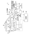
図1は、本発明の第1の実施形態の排気浄化システムを備えたディーゼルエンジンシステムの全体構成図である。まず、図1を参照して、本発明の排気浄化システムを備えたディーゼルエンジンシステムの全体構成について説明する。
<First Embodiment>
FIG. 1 is an overall configuration diagram of a diesel engine system including an exhaust purification system according to a first embodiment of the present invention. First, with reference to FIG. 1, the whole structure of the diesel engine system provided with the exhaust gas purification system of this invention is demonstrated.
図1に示したように、本発明のディーゼルエンジンシステム1は、エンジン10と、エンジン10に吸気ガス(空気)を送給する吸気通路12と、エンジン10から排出される排気ガスが通過する排気通路14とを備えおり、排気通路14には、通過する排気ガスを浄化する各種の後処理装置が配置されている。
As shown in FIG. 1, the
エンジン10においては、コモンレール10aにて蓄圧された高圧燃料が、不図示のコモンレール制御装置によって噴射時期および噴射量が制御され、シリンダ毎に設けられた燃料噴射弁11から各シリンダ内の燃焼室に向けて噴射される。噴射された高圧燃料は、吸気通路12から供給された吸気ガス(空気)との混合によって燃焼される。また、エンジン10には回転数検出器13が設けられており、該検出器13によって検出されたエンジン回転数は、後述する制御装置60に入力されるようになっている。また、エンジン10は、後述する冷却水通路(図1において不図示)を流れる冷却水によって冷却されるようになっている。
In the
制御装置60は、中央処理装置(CPU)、ランダムアクセスメモリ(RAM)、リードオンリメモリ(ROM)、およびI/Oインターフェイスなどからなるマイクロコンピュータで構成されている。上述した回転数検出器13やその他のセンサ類にて測定されたデータに関する信号は、I/Oインターフェイスを介してCPUに入力される。またCPUは、ROMに記憶されている制御プログラムと入力された信号に従って、各種の制御を実行するように構成されている。
The
また、吸気通路12と排気通路14との間には、過給機20が設けられている。過給機20は、排気通路14に配置されている排気タービン20bと吸気通路12に配置されているコンプレッサ20aとを有しており、該コンプレッサ20aは排気タービン20bによって同軸駆動される。また、吸気通路12にはインタークーラ16およびスロットルバルブ18が設けられており、コンプレッサ20aから吐出された圧縮空気が、インタークーラ16で冷却された後、スロットルバルブ18で流量が制御され、エンジン10の各シリンダ内の燃焼室に流入するようになっている。
A
また、排気通路14の排気タービン20bの下流には、上述した後処理装置として、前段酸化触媒22と、DPF装置24が配置されている。また、DPF装置24の下流側には、尿素水噴射装置32、SCR触媒34、および後段酸化触媒36からなるSCRシステム138が配置されている。
In addition, a
前段酸化触媒122は、排気ガス中の炭化水素(HC)や一酸化炭素(CO)を酸化除去するとともに、排気ガス中の一酸化窒素(NO)を酸化して二酸化窒素(NO2)を生成する機能を有する。また、DPF装置24は、排気ガス中に含まれるススなどのパーティキュレートマター(PM)をフィルタで捕集し、排気ガスから除去する装置である。また、DPF装置24に対しては、フィルタに堆積したPMを強制的に燃焼させてフィルタを再生する処置(強制再生運転)が定期的に実行される。
The
SCRシステム38は、アンモニア(NH3)をSCR触媒34の触媒作用の元で排気ガス中のNOXと反応させることで、NOXを二酸化窒素と水とに還元して無害化するシステムである。SCR触媒34に供給されるアンモニア(NH3)は、尿素水噴射装置32によって排気通路14に尿素水を噴射し、噴射した尿素水を排気ガスの排気温度で分解することで生成される。なお、噴射される尿素水は尿素水タンク32aに収容されている。また、SCR触媒34の下流側には後段酸化触媒36が配置されており、SCR触媒34からスリップしたNH3を酸化して無害化するようになっている。
The
また、排気通路14には、排気タービン20bの上流側から分岐して、吸気通路12の吸気スロットル18の下流側に接続される高圧EGR通路40が形成されており、エンジン10から排出された排気ガスの一部が吸気通路12に還流するようになっている。また、高圧EGR通路40には、通過する排気ガスを冷却するEGRクーラ42と還流する排気ガスの流量を制御するEGRバルブ44が配置されている。なお、本発明の排気浄化システムにおいて、これら高圧EGR通路40、EGRクーラ42およびEGRバルブ44は、必ずしも設置されている必要はない。
The
また、本実施形態では、図1に示したように、排気タービン20bの上流側にて排気通路14から分岐し、排気タービン20bを迂回して、前段酸化触媒22の上流側にて排気通路14と合流する過給機バイパス通路21が形成されている。また、排気通路14と過給機バイパス通路21との合流地点と前段酸化触媒22との間には、排気温センサ25が配置されており、後処理装置に流入する排気ガスの温度を測定している。排気温センサ25で測定された排気ガスの温度は、上述した制御装置60に入力されるようになっている。
Further, in the present embodiment, as shown in FIG. 1, the
また、過給機バイパス通路21の分岐地点には、第1バイパス弁23が配置されている。そして、第1バイパス弁23の弁開度を調節することで、過給機バイパス通路21を通過する排気ガスの流量と排気通路14を通って排気タービン20bを通過する流量とが制御される。また、この第1バイパス弁23は、制御装置60から送信される制御信号によって、その弁開度が制御されるようになっている。
A
排気ガスは、過給機20の排気タービン20bを通過すると、膨張して温度が低下する。このため、制御装置60によって第1バイパス弁23の弁開度を制御し、過給機バイパス通路21を通過(排気タービンを迂回)する排気ガスの流量を増やし、排気タービン20bを通過する排気ガスの流量を減らすことで、後処理装置に流入する排気ガスを昇温をさせることができる。すなわち、上述した過給機バイパス通路21と第1バイパス弁23、および該第1バイパス弁23を制御する制御装置60によって、本実施形態の昇温手段が構成されている。
When the exhaust gas passes through the
次に、本発明の排気浄化システムの制御フローについて、図2を基に説明する。
スタート後(S10)、先ず、エンジン運転状態を取得する(S11)。エンジン運転状態は、エンジン回転数および燃料噴射量に基づいて把握される。そして次に、後処理装置に流入する排気ガスの温度T1を取得する(S12)。この排気ガスの温度T1は、上述した排気温センサ25によって測定された排気ガスの温度として把握される。
Next, the control flow of the exhaust purification system of the present invention will be described with reference to FIG.
After the start (S10), first, the engine operating state is acquired (S11). The engine operating state is grasped based on the engine speed and the fuel injection amount. Next, the temperature T1 of the exhaust gas flowing into the aftertreatment device is acquired (S12). The temperature T1 of the exhaust gas is grasped as the temperature of the exhaust gas measured by the
次に、目標温度T2を取得する。目標温度T2は、エンジン回転数および燃料噴射量を入力データとする目標温度マップによって算出される。この際、DPF装置24が強制再生運転中か否かを判断し(S13)、強制再生中の場合は、強制再生運転用の目標温度マップによって目標温度T2を算出し(S14b)、強制再生中でない場合は、通常運転用の目標温度マップによって目標温度T2を算出する(S14a)。なお、これら強制再生運転用および通常運転用の目標温度マップは、制御装置60のROMに予め記憶されている。
Next, the target temperature T2 is acquired. The target temperature T2 is calculated by a target temperature map using the engine speed and the fuel injection amount as input data. At this time, it is determined whether or not the
そして次に、目標温度T2と後処理装置に流入する排気ガスの温度T1とを比較する(S15)。T2>T1の場合(S15においてYes)は、上述した第1バイパス弁23の弁開度を制御し、排気ガスの少なくとも一部が、排気タービン20bをバイパスして過給機バイパス通路21を通過するような制御(過給機バイパス制御)を実行する(S17)。また、T1>T2の場合(S15においてNo)は、過給機バイパス制御は実行せずに(S16)、終了する(S18)。
Next, the target temperature T2 is compared with the temperature T1 of the exhaust gas flowing into the aftertreatment device (S15). When T2> T1 (Yes in S15), the valve opening degree of the
また、上述した過給機バイパス制御を実行(S17)する場合、図3に示したようなフィードバック制御を行って第1バイパス弁23の弁開度を制御することで、後処理装置に流入する排気ガスの温度T1を精度よく目標温度T2に一致させることができる。
Further, when the supercharger bypass control described above is executed (S17), the feedback control as shown in FIG. 3 is performed to control the valve opening degree of the
このように本発明の排気浄化システムは、過給機バイパス通路21と第1バイパス弁23と制御装置60とからなる昇温手段を備えており、制御装置60によって第1バイパス弁23の弁開度を制御し、過給機バイパス通路21を通過(排気タービン20bを迂回)する排気ガスの流量を増やし、排気タービンを通過する排気ガスの流量を減らすことで、後処理装置に流入する排気ガスの昇温を図ることができる。このような本発明の排気浄化システムでは、レイトポスト噴射のように、燃費の悪化やオイルダイリュージョン等の問題が生ずることがない。また、エンジンに供給される吸気ガスの流量を絞るものでもないので、エンジンの燃焼が不安定になる恐れもない。
As described above, the exhaust purification system of the present invention includes the temperature raising means including the
<第2の実施形態>
図4は、本発明の第2の実施形態の排気浄化システムを備えたディーゼルエンジンシステムの全体構成図である。なお、本実施形態のディーゼルエンジンシステム1の全体構成は、上述した実施形態と基本的には同一の構成であり、同一の構成には同一の符号を付し、その詳細な説明を省略する。
<Second Embodiment>
FIG. 4 is an overall configuration diagram of a diesel engine system including an exhaust purification system according to a second embodiment of the present invention. The overall configuration of the
本実施形態では、上述した実施形態とは異なり、図4に示したように、吸気通路12から分岐し、インタークーラ16を迂回して、スロットルバルブ18の上流側にて吸気通路12と合流するインタークーラバイパス通路17が形成されている。また、インタークーラバイパス通路17の分岐地点には第2バイパス弁26が配置されており、第2バイパス弁26の弁開度を調節することで、インタークーラバイパス通路17を通過する排気ガスの流量と吸気通路12を通ってインタークーラ16を通過する流量とが制御される。この第2バイパス弁26は、制御装置60から送信される制御信号によって、その弁開度が制御されるようになっている。
In the present embodiment, unlike the above-described embodiment, as shown in FIG. 4, the air flows from the
吸気ガスは、インタークーラ16を通過すると、冷却されて温度が低下する。このため、制御装置60によって第2バイパス弁26を制御し、インタークーラバイパス通路17を通過(インタークーラ16を迂回)する吸気ガスの流量を増やし、インタークーラ16を通過する吸気ガスの流量を減らすことで、エンジン10に供給される吸気ガスの温度が上昇する。これにより、エンジン10から排出される排気ガスの温度も上昇し、後処理装置に流入する排気ガスを昇温させることができる。すなわち、上述したインタークーラバイパス通路17と第2バイパス弁26、および該第2バイパス弁26を制御する制御装置60によって、本実施形態の昇温手段が構成されている。
When the intake gas passes through the
また、上述したインタークーラバイパス通路17および第2バイパス弁26に加えて、又はこれらに替えて、図5に示すように、コンプレッサ20aの上流側の吸気通路12から分岐し、コンプレッサ20aおよびインタークーラ16を迂回して、スロットルバルブ18の上流側にて吸気通路12と合流するインタークーラバイパス通路17´を形成するとともに、インタークーラバイパス通路17´の分岐地点に第2バイパス弁26´を配置してもよい。コンプレッサ20aによって吸気ガスが圧縮(過給)されると、エンジン10に供給される吸気ガスの熱容量が大きくなるので、過給されていない場合と比べてエンジン10から排出される排気ガスの温度は低くなる。よって、制御装置60によって第2バイパス弁26´の弁開度を調節し、インタークーラバイパス通路17´を通過する排気ガスの流量を増やし、吸気通路12を通ってコンプレッサ20aおよびインタークーラ16を通過する流量を減らすことで、後処理装置に流入する排気ガスの昇温を図ることができる。
Further, in addition to or instead of the intercooler bypass passage 17 and the
次に、本実施形態の排気浄化システムの制御フローについて、図6を基に説明する。
なお、本実施形態の制御フローは、上述した実施形態と基本的には同様の制御フローになっており、同一のステップには同一の符号を付し、その詳細な説明を省略する。
Next, the control flow of the exhaust purification system of this embodiment will be described with reference to FIG.
Note that the control flow of this embodiment is basically the same control flow as that of the above-described embodiment, and the same steps are denoted by the same reference numerals and detailed description thereof is omitted.
本実施形態では、エンジン10が高負荷運転中の場合は、第2バイパス弁26によって、インタークーラバイパス通路17を通過する吸気ガスの流量と、インタークーラ16を通過する吸気ガスの流量とを制御することで、後処理装置に流入する排気ガスの温度が所定の設定温度となるように制御し(インタークーラバイパス制御)、エンジン10が高負荷運転中でない場合(低負荷運転中の場合)は、上述したインタークーラバイパス制御に加えて、第1バイパス弁23によって、過給機バイパス通路21を通過する排気ガスの流量と、排気タービン20bを通過する排気ガスの流量を制御することで、後処理装置に流入する排気ガスの温度が所定の設定温度となるような制御(過給機バイパス制御)を実行する点が、上述した実施形態とは異なっている。
In the present embodiment, when the
具体的には、図6に示したように、S15において、目標温度T2と後処理装置に流入する排気ガスの温度T1とを比較した後、T2>T1の場合(S15においてYes)において、エンジン10が所定以上の負荷状態にある高負荷運転中か否かを判定する(S19)。高負荷運転か否かの判定は、S11において取得したエンジン運転状態を基に、制御装置60のROMに予め記憶されているエンジン運転状態判定マップによって判定される。
Specifically, as shown in FIG. 6, after comparing the target temperature T2 with the temperature T1 of the exhaust gas flowing into the aftertreatment device in S15, the engine in T2> T1 (Yes in S15). It is determined whether or not the vehicle is in a high load operation in which 10 is in a load state greater than or equal to a predetermined value (S19). The determination as to whether or not it is a high load operation is made based on the engine operation state determination map stored in advance in the ROM of the
そして、高負荷運転中の場合(S19においてYes)は、制御装置60によって第2バイパス弁26の弁開度を調節して、インタークーラバイパス制御のみを実行する(S19b)。一方、エンジン10が所定未満の負荷状態にある低負荷運転中の場合(S19においてNo)は、インタークーラバイパス制御に加えて、制御装置60によって第1バイパス弁23の弁開度を調節して、過給機バイパス制御を実行する(S19a)。
When the high load operation is being performed (Yes in S19), the
このような本実施形態の排気浄化システムは、高負荷運転時の場合は、過給機20の駆動を優先させるために、第1バイパス弁23による昇温制御(過給機バイパス制御)は行わずに、第2バイパス弁26による昇温制御(インタークーラバイパス制御)のみを行って、後処理装置に流入する排気ガスの昇温を図っている。一方、低負荷運転時の場合は、過給機20の駆動よりも排気ガスの昇温を優先させ、第2バイパス弁26による排気ガスの昇温制御(インタークーラバイパス制御)に加えて、第1バイパス弁23によっても排気ガスの昇温制御(過給機バイパス制御)を行っている。すなわち本実施形態の制御フローによれば、エンジンの負荷状態に応じた適切な昇温制御を行うことができるようになっている。
In such an exhaust purification system of the present embodiment, in the case of high load operation, in order to give priority to the drive of the
<第3の実施形態>
次に、本発明の第3の実施形態について、図7に基づいて説明する。
なお、本実施形態のディーゼルエンジンシステム1の全体構成は、上述した実施形態と基本的には同一の構成となっている。
<Third Embodiment>
Next, a third embodiment of the present invention will be described with reference to FIG.
Note that the overall configuration of the
本実施形態では、エンジン10を冷却する冷却水が通過する冷却水通路が、図7に示すような構成となっている。
すなわち、本実施形態の冷却水通路50は、通過する冷却水を冷却するラジエータ56を備えており、ラジエータ56とエンジン10との間には、環状通路51が形成されている。環状通路51には、冷却水を一方向に吐出する冷却水ポンプ58が設けられており、この冷却水ポンプ58によって、冷却水が環状通路51を循環するようになっている。
In the present embodiment, the cooling water passage through which the cooling water for cooling the
That is, the cooling
また、環状通路51のラジエータ56の上流側には、環状通路51から分岐し、ラジエータ56を迂回して、冷却水ポンプ58の下流側にて環状通路51と合流するラジエータバイパス通路52が形成されている。また、環状通路51とラジエータバイパス通路52の分岐地点には冷却水バイパス弁54が配置されており、その弁開度を調節することで、ラジエータバイパス通路52を通過(ラジエータ56を迂回)する冷却水の流量とラジエータ56を通過する冷却水の流量とが制御される。また、この冷却水バイパス弁54は、制御装置60から送信される制御信号によって、その弁開度が制御されるようになっている。
A
また、冷却水通路50には、EGRクーラ42を冷却するEGRクーラ通路53が形成されている。EGRクーラ通路53は、冷却水ポンプ58の下流側から分岐し、エンジン10を迂回して、エンジン10の下流側にて環状通路51と合流している。また、エンジン10の下流側には冷却水温センサ55が配置されており、通過する冷却水の温度を測定している。冷却水温センサ55にて測定された冷却水の温度は、制御装置60に入力される。
The cooling
冷却水は、ラジエータ56を通過すると冷却されて温度が低下する。エンジン10から排出される排気ガスの温度は、エンジン10を冷却する冷却水の温度に比例することから、エンジン10を通過する冷却水の温度を高めることで、エンジン10から排出される排気ガスを昇温させることができる。よって、制御装置60によって冷却水バイパス弁54を制御し、ラジエータバイパス通路52を通過(ラジエータ56を迂回)する冷却水の流量を増やし、ラジエータ56を通過する冷却水の流量を減らすことで、エンジン10を通過する冷却水を所定の設定温度に昇温させ、これにより後処理装置に流入する排気ガスを昇温させることができる。すなわち、上述したラジエータバイパス通路52と冷却水バイパス弁54、および該冷却水バイパス弁54を制御する制御装置60によって、本実施形態の昇温手段が構成されている。
When the cooling water passes through the
また一般的に、エンジン10を通過した冷却水は、所定の設定温度(例えば80℃)となるようにサーモスタットによって制御されている。サーモスタットによる温度制御は、冷却水の温度等に応じてサーモスタット内部のバルブが自動的に開閉することで制御されている。このため、上述した冷却水の設定温度は簡単には変更できないようになっている。これに対して本発明では、制御装置60によって冷却水バイパス弁54を制御可能に構成したことから、冷却水の設定温度自体も制御装置60によって簡単に変更ができる。したがって、DPF強制再生運転時において排気ガスの早期昇温を図りたい場合には、冷却水の設定温度を通常運転時よりも高く設定(例えば85℃)し、この設定温度に応じて冷却水の流路を制御することで、DPF装置24に流入する排気ガスの昇温を図ることができる。
Generally, the cooling water that has passed through the
次に、本実施形態の排気浄化システムの制御フローについて、図8を基に説明する。
なお、以下の制御フローでは、上述した冷却水バイパス弁54による昇温制御が、DPF強制再生運転時に実行されるものとして説明する。
Next, the control flow of the exhaust purification system of this embodiment will be described with reference to FIG.
In the following control flow, description will be made assuming that the above-described temperature rise control by the cooling
スタート後(S20)、先ず、エンジン運転状態を取得する(S21)。エンジン運転状態は、エンジン回転数および燃料噴射量に基づいて把握される。そして次に、エンジン10出口の冷却水の温度Tw1を取得する(S22)。この冷却水の温度Tw1は、上述した冷却水温センサ55によって測定された冷却水の温度として把握される。なお、冷却水の温度Tw1は、エンジン10を通過する冷却水の温度を精度よく把握するため、エンジン10の近くで測定されるのが好ましく、例えば、エンジン10の入口やエンジン10周囲の冷却水通路50(ウォータージャケット)で測定することもできる。
After the start (S20), first, the engine operating state is acquired (S21). The engine operating state is grasped based on the engine speed and the fuel injection amount. Next, the temperature Tw1 of the cooling water at the outlet of the
次に、冷却水の目標温度Tw2を取得する(S23)。目標温度Tw2は、エンジン回転数および燃料噴射量を入力データとする冷却水目標温度マップによって算出される。なお、冷却水目標温度マップは、制御装置60のROMに予め記憶されている。
Next, the target temperature Tw2 for the cooling water is acquired (S23). The target temperature Tw2 is calculated by a cooling water target temperature map using the engine speed and the fuel injection amount as input data. The cooling water target temperature map is stored in advance in the ROM of the
そして次に、目標温度Tw2とエンジン10出口の冷却水の温度Tw1とを比較する(S24)。Tw2>Tw1の場合(S24においてYes)は、上述した冷却水バイパス弁54の弁開度を制御し、冷却水の少なくとも一部が、ラジエータ56をバイパスしてラジエータバイパス通路52を通過するように制御するラジエータバイパス制御を実行する(S26)。また、Tw1>Tw2の場合(S24においてNo)は、ラジエータバイパス制御は実行せずに(S25)、終了する(S27)。
Next, the target temperature Tw2 is compared with the cooling water temperature Tw1 at the outlet of the engine 10 (S24). When Tw2> Tw1 (Yes in S24), the valve opening degree of the cooling
この際、上述した図3に示したようなフィードバック制御によって、冷却水バイパス弁54の弁開度を制御することで、エンジン10を通過する冷却水の温度Tw1を精度よく目標温度Tw2に一致させることができる。また、本実施形態においても、上述した実施形態と同様に、後処理装置に流入する排気ガスの温度が所定の設定温度となるように制御することもできる。
At this time, the temperature Tw1 of the cooling water passing through the
以上、本発明の好ましい形態について説明したが、本発明は上記の形態に限定されるものではなく、本発明の目的を逸脱しない範囲での種々の変更が可能である。 As mentioned above, although the preferable form of this invention was demonstrated, this invention is not limited to said form, A various change in the range which does not deviate from the objective of this invention is possible.
本発明によれば、エンジンと、エンジンに供給される吸気ガスが通過する吸気通路と、エンジンから排出される排気ガスが通過する排気通路と、排気通路に設けられて通過する排気ガスを浄化する後処理装置と、エンジンを冷却する冷却水が通過する冷却水通路とを備えた排気浄化システムとして、ディーゼルエンジンなどに好適に利用することができる。 According to the present invention, the engine, the intake passage through which the intake gas supplied to the engine passes, the exhaust passage through which the exhaust gas discharged from the engine passes, and the exhaust gas that is provided in the exhaust passage and passes therethrough are purified. As an exhaust purification system including an aftertreatment device and a cooling water passage through which cooling water for cooling the engine passes, the exhaust purification system can be suitably used for a diesel engine or the like.
1 ディーゼルエンジンシステム、
10 エンジン
10a コモンレール
11 燃料噴射弁
12 吸気通路
13 回転数検出器
14 排気通路
16 インタークーラ
17 インタークーラバイパス通路(昇温手段)
18 スロットルバルブ
20 過給機
20a コンプレッサ
20b 排気タービン
21 過給機バイパス通路(昇温手段)
22 前段酸化触媒(後処理装置)
23 第1バイパス弁(昇温手段)
24 DPF装置(後処理装置)
25 排気温センサ
26 第2バイパス弁(昇温手段)
32 尿素水噴射装置
34 SCR触媒(後処理装置)
36 後段酸化触媒(後処理装置)
38 SCRシステム
40 高圧EGR通路
42 EGRクーラ
44 EGRバルブ
50 冷却水通路
51 環状通路
52 ラジエータバイパス通路(昇温手段)
53 EGRクーラ通路
54 冷却水バイパス弁(昇温手段)
55 冷却水温センサ
56 ラジエータ
58 冷却水ポンプ
60 制御装置(昇温手段)
1 diesel engine system,
10
18
22 Pre-stage oxidation catalyst (post-treatment equipment)
23 First bypass valve (temperature raising means)
24 DPF device (post-processing device)
25
32 Urea
36 Post-stage oxidation catalyst (post-treatment equipment)
38
53 EGR
55 Cooling
Claims (6)
前記吸気ガス、排気ガス、又は冷却水の内、少なくともいずれか一つの流体の流路を制御することで、前記後処理装置に流入する排気ガスの温度を上昇させる昇温手段を備えたことを特徴とする排気浄化システム。 An engine, an intake passage through which intake gas supplied to the engine passes, an exhaust passage through which exhaust gas discharged from the engine passes, and a post-processing device that is provided in the exhaust passage and purifies exhaust gas that passes through the exhaust passage And an exhaust purification system comprising a cooling water passage through which cooling water for cooling the engine passes,
A temperature raising means for raising the temperature of the exhaust gas flowing into the aftertreatment device by controlling a flow path of at least one of the intake gas, the exhaust gas, and the cooling water; A featured exhaust purification system.
前記エンジンが所定未満の負荷状態にある低負荷運転時の場合は、前記第2バイパス弁による昇温制御に加えて、前記第1バイパス弁によって、前記過給機バイパス通路を通過する排気ガスの流量と、前記排気タービンを通過する排気ガスの流量とを制御することで、前記後処理装置に流入する排気ガスの温度が所定の設定温度となるように制御することを特徴とする請求項3に記載の排気浄化システム。 In the case of a high load operation in which the engine is in a load state greater than or equal to a predetermined load, the flow rate of the intake gas passing through the intercooler bypass passage by the second bypass valve and the flow rate of the intake gas passing through the intercooler are By controlling, the temperature of the exhaust gas flowing into the aftertreatment device is controlled to be a predetermined set temperature,
In the case of low load operation in which the engine is under a predetermined load state, in addition to the temperature increase control by the second bypass valve, the exhaust gas passing through the supercharger bypass passage by the first bypass valve is added. The control of controlling the flow rate and the flow rate of exhaust gas passing through the exhaust turbine so that the temperature of the exhaust gas flowing into the aftertreatment device becomes a predetermined set temperature. The exhaust gas purification system described in 1.
前記昇温手段が、前記環状通路から前記ラジエータを迂回するように分岐するラジエータバイパス通路と、前記ラジエータバイパス通路を通過する冷却水の流量と前記ラジエータを迂回する冷却水の流量とを制御する冷却水バイパス弁と、前記エンジンを通過する冷却水の温度及び/又は前記後処理装置に流入する排気ガスの温度が所定の設定温度となるように、前記冷却水バイパス弁を制御する制御装置とを含むことを特徴とする請求項1から4のいずれかに記載の排気浄化システム。 The cooling water passage includes a radiator for cooling the cooling water passing therethrough, and an annular passage formed so that the cooling water circulates between the radiator and the engine,
The temperature raising means controls a radiator bypass passage that branches from the annular passage so as to bypass the radiator, a cooling flow that controls a flow rate of cooling water that passes through the radiator bypass passage, and a flow rate of cooling water that bypasses the radiator A water bypass valve, and a control device that controls the cooling water bypass valve so that the temperature of the cooling water passing through the engine and / or the temperature of the exhaust gas flowing into the aftertreatment device becomes a predetermined set temperature. The exhaust gas purification system according to any one of claims 1 to 4, further comprising:
前記冷却水バイパス弁による昇温制御が、前記DPF装置に堆積したPMを強制的に燃焼させるDPF強制再生運転時に実行されることを特徴とする請求項5に記載の排気浄化システム。 The post-processing device includes at least a DPF device;
The exhaust gas purification system according to claim 5, wherein the temperature rise control by the cooling water bypass valve is executed during a DPF forced regeneration operation in which PM accumulated in the DPF device is forcibly burned.
Priority Applications (1)
| Application Number | Priority Date | Filing Date | Title |
|---|---|---|---|
| JP2011259771A JP2013113204A (en) | 2011-11-29 | 2011-11-29 | Exhaust emission control system for engine |
Applications Claiming Priority (1)
| Application Number | Priority Date | Filing Date | Title |
|---|---|---|---|
| JP2011259771A JP2013113204A (en) | 2011-11-29 | 2011-11-29 | Exhaust emission control system for engine |
Publications (1)
| Publication Number | Publication Date |
|---|---|
| JP2013113204A true JP2013113204A (en) | 2013-06-10 |
Family
ID=48708973
Family Applications (1)
| Application Number | Title | Priority Date | Filing Date |
|---|---|---|---|
| JP2011259771A Pending JP2013113204A (en) | 2011-11-29 | 2011-11-29 | Exhaust emission control system for engine |
Country Status (1)
| Country | Link |
|---|---|
| JP (1) | JP2013113204A (en) |
Cited By (5)
| Publication number | Priority date | Publication date | Assignee | Title |
|---|---|---|---|---|
| JP2015096708A (en) * | 2013-11-15 | 2015-05-21 | いすゞ自動車株式会社 | Engine heat removal amount control system |
| JP2018009527A (en) * | 2016-07-14 | 2018-01-18 | ヤンマー株式会社 | Device and method for controlling internal combustion engine |
| KR20180122713A (en) * | 2016-07-14 | 2018-11-13 | 얀마 가부시키가이샤 | Control device of internal combustion engine and control method of internal combustion engine |
| KR20180122714A (en) * | 2016-07-14 | 2018-11-13 | 얀마 가부시키가이샤 | Control device of internal combustion engine and control method of internal combustion engine |
| CN109339907A (en) * | 2018-12-18 | 2019-02-15 | 河北工业大学 | A kind of DPF system of the miniaturization with heat management |
-
2011
- 2011-11-29 JP JP2011259771A patent/JP2013113204A/en active Pending
Cited By (15)
| Publication number | Priority date | Publication date | Assignee | Title |
|---|---|---|---|---|
| JP2015096708A (en) * | 2013-11-15 | 2015-05-21 | いすゞ自動車株式会社 | Engine heat removal amount control system |
| KR102021256B1 (en) | 2016-07-14 | 2019-09-11 | 얀마 가부시키가이샤 | Control device of internal combustion engine and control method of internal combustion engine |
| EP3486460A4 (en) * | 2016-07-14 | 2019-05-22 | Yanmar Co., Ltd. | Control device for internal combustion engine and control method for internal combustion engine |
| KR20180122713A (en) * | 2016-07-14 | 2018-11-13 | 얀마 가부시키가이샤 | Control device of internal combustion engine and control method of internal combustion engine |
| KR20180122712A (en) * | 2016-07-14 | 2018-11-13 | 얀마 가부시키가이샤 | Control device of internal combustion engine and control method of internal combustion engine |
| KR20180122714A (en) * | 2016-07-14 | 2018-11-13 | 얀마 가부시키가이샤 | Control device of internal combustion engine and control method of internal combustion engine |
| CN109415984B (en) * | 2016-07-14 | 2021-08-03 | 洋马动力科技有限公司 | Control device for internal combustion engine and control method for internal combustion engine |
| CN109415984A (en) * | 2016-07-14 | 2019-03-01 | 洋马株式会社 | The control device of internal combustion engine and the control method of internal combustion engine |
| WO2018012305A1 (en) * | 2016-07-14 | 2018-01-18 | ヤンマー株式会社 | Control device for internal combustion engine and control method for internal combustion engine |
| JP2018009527A (en) * | 2016-07-14 | 2018-01-18 | ヤンマー株式会社 | Device and method for controlling internal combustion engine |
| KR102086276B1 (en) * | 2016-07-14 | 2020-03-06 | 얀마 가부시키가이샤 | Control device of internal combustion engine and control method of internal combustion engine |
| KR102086277B1 (en) | 2016-07-14 | 2020-03-06 | 얀마 가부시키가이샤 | Control device of internal combustion engine and control method of internal combustion engine |
| US10947934B2 (en) | 2016-07-14 | 2021-03-16 | Yanmar Power Technology Co., Ltd. | Control device for internal combustion engine and control method for internal combustion engine |
| CN109339907A (en) * | 2018-12-18 | 2019-02-15 | 河北工业大学 | A kind of DPF system of the miniaturization with heat management |
| CN109339907B (en) * | 2018-12-18 | 2023-09-29 | 河北工业大学 | Miniaturized DPF system with thermal management |
Similar Documents
| Publication | Publication Date | Title |
|---|---|---|
| US7251932B2 (en) | Exhaust system and method for controlling exhaust gas flow and temperature through regenerable exhaust gas treatment devices | |
| WO2007066835A1 (en) | Exhaust gas purification system for internal combustion engine | |
| JPWO2014016909A1 (en) | Exhaust purification device, method for thawing liquid reducing agent or precursor thereof | |
| JP2013142363A (en) | Exhaust emission control device of diesel engine | |
| JP2010121521A (en) | After treatment system for engine | |
| JP5316041B2 (en) | Engine exhaust purification system | |
| JP2008157188A (en) | Emission purifying device | |
| JP2013113204A (en) | Exhaust emission control system for engine | |
| JP4161575B2 (en) | Exhaust gas purification device for internal combustion engine | |
| JP4857957B2 (en) | Engine control device | |
| US20190186315A1 (en) | Engine | |
| JP4613787B2 (en) | Exhaust gas purification device for internal combustion engine | |
| JP6589365B2 (en) | Exhaust gas purification system | |
| JP6729473B2 (en) | Filter regeneration control device and filter regeneration control method | |
| JP2010223041A (en) | Exhaust emission control device for engine | |
| JP2006266221A (en) | Rising temperature controller of aftertreatment device | |
| JP6805948B2 (en) | Exhaust purification device | |
| JP2007040223A (en) | Exhaust emission control device | |
| JP2010196569A (en) | Exhaust emission control system and exhaust emission control method | |
| KR101734254B1 (en) | Bypass control method of exhaust gas | |
| JP2006266220A (en) | Rising temperature controller of aftertreatment device | |
| JP2005048701A (en) | Exhaust emission control device for engine | |
| WO2022045318A1 (en) | Exhaust gas purification system for internal combustion engine | |
| JP6733595B2 (en) | Filter regeneration control device and filter regeneration control method | |
| KR101755471B1 (en) | Exhaust gas processing apparatus and method thereof |