JP6638710B2 - Battery device - Google Patents
Battery device Download PDFInfo
- Publication number
- JP6638710B2 JP6638710B2 JP2017179311A JP2017179311A JP6638710B2 JP 6638710 B2 JP6638710 B2 JP 6638710B2 JP 2017179311 A JP2017179311 A JP 2017179311A JP 2017179311 A JP2017179311 A JP 2017179311A JP 6638710 B2 JP6638710 B2 JP 6638710B2
- Authority
- JP
- Japan
- Prior art keywords
- battery
- heat
- switch device
- circuit board
- power element
- Prior art date
- Legal status (The legal status is an assumption and is not a legal conclusion. Google has not performed a legal analysis and makes no representation as to the accuracy of the status listed.)
- Active
Links
- 230000005855 radiation Effects 0.000 claims description 27
- 239000000463 material Substances 0.000 claims description 15
- 230000000630 rising effect Effects 0.000 claims description 6
- 230000000694 effects Effects 0.000 description 20
- 230000017525 heat dissipation Effects 0.000 description 7
- 230000002093 peripheral effect Effects 0.000 description 7
- 239000011347 resin Substances 0.000 description 7
- 229920005989 resin Polymers 0.000 description 7
- 230000020169 heat generation Effects 0.000 description 6
- RYGMFSIKBFXOCR-UHFFFAOYSA-N Copper Chemical compound [Cu] RYGMFSIKBFXOCR-UHFFFAOYSA-N 0.000 description 4
- 229910045601 alloy Inorganic materials 0.000 description 4
- 239000000956 alloy Substances 0.000 description 4
- 229910052782 aluminium Inorganic materials 0.000 description 4
- XAGFODPZIPBFFR-UHFFFAOYSA-N aluminium Chemical compound [Al] XAGFODPZIPBFFR-UHFFFAOYSA-N 0.000 description 4
- 229910052802 copper Inorganic materials 0.000 description 4
- 239000010949 copper Substances 0.000 description 4
- 230000001172 regenerating effect Effects 0.000 description 4
- 239000000758 substrate Substances 0.000 description 4
- HBBGRARXTFLTSG-UHFFFAOYSA-N Lithium ion Chemical compound [Li+] HBBGRARXTFLTSG-UHFFFAOYSA-N 0.000 description 3
- 238000007599 discharging Methods 0.000 description 3
- 230000001747 exhibiting effect Effects 0.000 description 3
- 229910001416 lithium ion Inorganic materials 0.000 description 3
- 239000004065 semiconductor Substances 0.000 description 3
- 239000000853 adhesive Substances 0.000 description 2
- 230000001070 adhesive effect Effects 0.000 description 2
- 238000010586 diagram Methods 0.000 description 2
- 230000005611 electricity Effects 0.000 description 2
- 238000009434 installation Methods 0.000 description 2
- 229910052751 metal Inorganic materials 0.000 description 2
- 239000002184 metal Substances 0.000 description 2
- 238000012986 modification Methods 0.000 description 2
- 230000004048 modification Effects 0.000 description 2
- 238000010248 power generation Methods 0.000 description 2
- 238000007789 sealing Methods 0.000 description 2
- 230000001629 suppression Effects 0.000 description 2
- XUIMIQQOPSSXEZ-UHFFFAOYSA-N Silicon Chemical compound [Si] XUIMIQQOPSSXEZ-UHFFFAOYSA-N 0.000 description 1
- 230000002159 abnormal effect Effects 0.000 description 1
- 230000005856 abnormality Effects 0.000 description 1
- 230000004888 barrier function Effects 0.000 description 1
- 238000007664 blowing Methods 0.000 description 1
- 238000002485 combustion reaction Methods 0.000 description 1
- 238000004891 communication Methods 0.000 description 1
- 239000000470 constituent Substances 0.000 description 1
- 239000012809 cooling fluid Substances 0.000 description 1
- 238000010292 electrical insulation Methods 0.000 description 1
- 239000012777 electrically insulating material Substances 0.000 description 1
- 239000003792 electrolyte Substances 0.000 description 1
- 239000004519 grease Substances 0.000 description 1
- 238000010438 heat treatment Methods 0.000 description 1
- 239000011810 insulating material Substances 0.000 description 1
- 238000003475 lamination Methods 0.000 description 1
- 229910052987 metal hydride Inorganic materials 0.000 description 1
- 150000002739 metals Chemical class 0.000 description 1
- 229910052710 silicon Inorganic materials 0.000 description 1
- 239000010703 silicon Substances 0.000 description 1
- 239000002210 silicon-based material Substances 0.000 description 1
- 238000005476 soldering Methods 0.000 description 1
- 239000007858 starting material Substances 0.000 description 1
- XLYOFNOQVPJJNP-UHFFFAOYSA-N water Substances O XLYOFNOQVPJJNP-UHFFFAOYSA-N 0.000 description 1
- 238000003466 welding Methods 0.000 description 1
Images


Classifications
-
- H—ELECTRICITY
- H02—GENERATION; CONVERSION OR DISTRIBUTION OF ELECTRIC POWER
- H02J—CIRCUIT ARRANGEMENTS OR SYSTEMS FOR SUPPLYING OR DISTRIBUTING ELECTRIC POWER; SYSTEMS FOR STORING ELECTRIC ENERGY
- H02J7/00—Circuit arrangements for charging or depolarising batteries or for supplying loads from batteries
- H02J7/0029—Circuit arrangements for charging or depolarising batteries or for supplying loads from batteries with safety or protection devices or circuits
- H02J7/00309—Overheat or overtemperature protection
-
- H—ELECTRICITY
- H01—ELECTRIC ELEMENTS
- H01M—PROCESSES OR MEANS, e.g. BATTERIES, FOR THE DIRECT CONVERSION OF CHEMICAL ENERGY INTO ELECTRICAL ENERGY
- H01M10/00—Secondary cells; Manufacture thereof
- H01M10/42—Methods or arrangements for servicing or maintenance of secondary cells or secondary half-cells
- H01M10/425—Structural combination with electronic components, e.g. electronic circuits integrated to the outside of the casing
-
- H—ELECTRICITY
- H01—ELECTRIC ELEMENTS
- H01M—PROCESSES OR MEANS, e.g. BATTERIES, FOR THE DIRECT CONVERSION OF CHEMICAL ENERGY INTO ELECTRICAL ENERGY
- H01M10/00—Secondary cells; Manufacture thereof
- H01M10/60—Heating or cooling; Temperature control
- H01M10/61—Types of temperature control
- H01M10/617—Types of temperature control for achieving uniformity or desired distribution of temperature
-
- H—ELECTRICITY
- H01—ELECTRIC ELEMENTS
- H01M—PROCESSES OR MEANS, e.g. BATTERIES, FOR THE DIRECT CONVERSION OF CHEMICAL ENERGY INTO ELECTRICAL ENERGY
- H01M10/00—Secondary cells; Manufacture thereof
- H01M10/60—Heating or cooling; Temperature control
- H01M10/62—Heating or cooling; Temperature control specially adapted for specific applications
- H01M10/625—Vehicles
-
- H—ELECTRICITY
- H01—ELECTRIC ELEMENTS
- H01M—PROCESSES OR MEANS, e.g. BATTERIES, FOR THE DIRECT CONVERSION OF CHEMICAL ENERGY INTO ELECTRICAL ENERGY
- H01M10/00—Secondary cells; Manufacture thereof
- H01M10/60—Heating or cooling; Temperature control
- H01M10/65—Means for temperature control structurally associated with the cells
- H01M10/655—Solid structures for heat exchange or heat conduction
- H01M10/6551—Surfaces specially adapted for heat dissipation or radiation, e.g. fins or coatings
-
- H—ELECTRICITY
- H02—GENERATION; CONVERSION OR DISTRIBUTION OF ELECTRIC POWER
- H02J—CIRCUIT ARRANGEMENTS OR SYSTEMS FOR SUPPLYING OR DISTRIBUTING ELECTRIC POWER; SYSTEMS FOR STORING ELECTRIC ENERGY
- H02J7/00—Circuit arrangements for charging or depolarising batteries or for supplying loads from batteries
- H02J7/0068—Battery or charger load switching, e.g. concurrent charging and load supply
-
- H—ELECTRICITY
- H01—ELECTRIC ELEMENTS
- H01M—PROCESSES OR MEANS, e.g. BATTERIES, FOR THE DIRECT CONVERSION OF CHEMICAL ENERGY INTO ELECTRICAL ENERGY
- H01M10/00—Secondary cells; Manufacture thereof
- H01M10/60—Heating or cooling; Temperature control
- H01M10/66—Heat-exchange relationships between the cells and other systems, e.g. central heating systems or fuel cells
- H01M10/667—Heat-exchange relationships between the cells and other systems, e.g. central heating systems or fuel cells the system being an electronic component, e.g. a CPU, an inverter or a capacitor
-
- H—ELECTRICITY
- H01—ELECTRIC ELEMENTS
- H01M—PROCESSES OR MEANS, e.g. BATTERIES, FOR THE DIRECT CONVERSION OF CHEMICAL ENERGY INTO ELECTRICAL ENERGY
- H01M10/00—Secondary cells; Manufacture thereof
- H01M10/42—Methods or arrangements for servicing or maintenance of secondary cells or secondary half-cells
- H01M10/425—Structural combination with electronic components, e.g. electronic circuits integrated to the outside of the casing
- H01M2010/4271—Battery management systems including electronic circuits, e.g. control of current or voltage to keep battery in healthy state, cell balancing
-
- H—ELECTRICITY
- H01—ELECTRIC ELEMENTS
- H01M—PROCESSES OR MEANS, e.g. BATTERIES, FOR THE DIRECT CONVERSION OF CHEMICAL ENERGY INTO ELECTRICAL ENERGY
- H01M2220/00—Batteries for particular applications
- H01M2220/20—Batteries in motive systems, e.g. vehicle, ship, plane
-
- H—ELECTRICITY
- H02—GENERATION; CONVERSION OR DISTRIBUTION OF ELECTRIC POWER
- H02J—CIRCUIT ARRANGEMENTS OR SYSTEMS FOR SUPPLYING OR DISTRIBUTING ELECTRIC POWER; SYSTEMS FOR STORING ELECTRIC ENERGY
- H02J7/00—Circuit arrangements for charging or depolarising batteries or for supplying loads from batteries
- H02J7/0029—Circuit arrangements for charging or depolarising batteries or for supplying loads from batteries with safety or protection devices or circuits
- H02J7/0031—Circuit arrangements for charging or depolarising batteries or for supplying loads from batteries with safety or protection devices or circuits using battery or load disconnect circuits
-
- Y—GENERAL TAGGING OF NEW TECHNOLOGICAL DEVELOPMENTS; GENERAL TAGGING OF CROSS-SECTIONAL TECHNOLOGIES SPANNING OVER SEVERAL SECTIONS OF THE IPC; TECHNICAL SUBJECTS COVERED BY FORMER USPC CROSS-REFERENCE ART COLLECTIONS [XRACs] AND DIGESTS
- Y02—TECHNOLOGIES OR APPLICATIONS FOR MITIGATION OR ADAPTATION AGAINST CLIMATE CHANGE
- Y02E—REDUCTION OF GREENHOUSE GAS [GHG] EMISSIONS, RELATED TO ENERGY GENERATION, TRANSMISSION OR DISTRIBUTION
- Y02E60/00—Enabling technologies; Technologies with a potential or indirect contribution to GHG emissions mitigation
- Y02E60/10—Energy storage using batteries
Description
この明細書における開示は、電池装置に関する。 The disclosure in this specification relates to a battery device.
特許文献1には、組電池に対する電力の入出力を制御するパワー素子を備える電池ユニットが開示されている。パワー素子は制御基板における、組電池に重ならない位置にある第2基板部に実装されている。
特許文献1の電池ユニットは、電力制御用のパワー素子が制御基板に実装されているため、パワー素子よりも低い耐熱温度である制御基板に係る耐熱温度の制約を受けることになる。この耐熱温度上の制約のために、スイッチ装置の発熱を抑えることが求められ、必要なスイッチ性能を発揮させることができないという課題がある。
In the battery unit of
このような課題に鑑み、この明細書における開示の目的は、電池に対する電力の入出力を制御するスイッチ装置についてその性能を発揮させることが可能な電池装置を提供することである。 In view of such a problem, an object of the disclosure in this specification is to provide a battery device that can exhibit the performance of a switch device that controls input and output of power to and from a battery.
この明細書に開示された複数の態様は、それぞれの目的を達成するために、互いに異なる技術的手段を採用する。また、特許請求の範囲およびこの項に記載した括弧内の符号は、ひとつの態様として後述する実施形態に記載の具体的手段との対応関係を示す一例であって、技術的範囲を限定するものではない。 The embodiments disclosed in this specification employ different technical means from each other in order to achieve the respective objects. Further, the reference numerals in the claims and the parentheses described in this section are examples showing a correspondence relationship with specific means described in the embodiment described below as one aspect, and limit the technical scope. is not.
開示された電池装置のひとつは、電池(13)と、電池と電気的に接続されている回路基板(2)と、電池に対する電力の入出力を制御するスイッチ装置であって、外面を形成する外装部(30)が回路基板から離間した状態で設置されているスイッチ装置(3,4)と、熱伝導性を有する材質によって形成されている放熱部材であって、スイッチ装置の熱が移動可能なようにスイッチ装置の外装部に直接または熱伝導性部材(5)を介して間接的に接触している放熱部材(6,106,206,306,406)と、スイッチ装置の外装部から放熱部材を介して、電池が収容されているベースケース(15)のベース部(15a)に熱伝達する伝熱経路と、を備え、回路基板は、放熱部材とは別個の部材であってベース部から分岐するように延びる部材に固定されている。 One of the disclosed battery devices is a battery (13), a circuit board (2) electrically connected to the battery, and a switch device for controlling input and output of power to and from the battery, forming an outer surface. A switch device (3, 4) in which the exterior part (30) is separated from the circuit board, and a heat radiating member formed of a material having thermal conductivity, wherein heat of the switch device is movable. The heat dissipating members (6, 106, 206, 306, 406) which are in direct contact with the exterior of the switch device or indirectly via the heat conductive member (5), and radiate heat from the exterior of the switch device. And a heat transfer path for transferring heat to the base portion (15a) of the base case (15) containing the battery via the member. Branch from Extending member that is fixed.
この電池装置によれば、スイッチ装置は外装部が回路基板から離間した状態であって、スイッチ装置の熱が移動可能なように外装部が直接または熱伝導性部材を介して間接的に放熱部材に接触している。これによれば、スイッチ装置の熱は、回路基板に移動するよりも放熱部材に速やかに移動するので、回路基板に対する熱的影響を抑えるためにスイッチ装置の発熱を抑える手段を講じる必要がない電池装置が得られる。また、回路基板の耐熱温度がボトルネックになってスイッチ装置の性能を十分に発揮できない事態を回避できる。したがって、回路基板の耐熱温度の制約を受けないようにスイッチ装置の性能を発揮させることが可能な電池装置を提供できる。 According to this battery device, the switch device is in a state in which the outer portion is separated from the circuit board, and the outer portion is directly or indirectly through the heat conductive member so that heat of the switch device can move. Is in contact with According to this, since the heat of the switch device moves more quickly to the heat radiation member than to the circuit board, it is not necessary to take measures to suppress the heat generation of the switch device in order to suppress the thermal effect on the circuit board. A device is obtained. Further, it is possible to avoid a situation where the heat resistance temperature of the circuit board becomes a bottleneck and the performance of the switch device cannot be sufficiently exhibited. Therefore, it is possible to provide a battery device capable of exhibiting the performance of the switch device without being restricted by the heat-resistant temperature of the circuit board.
以下に、図面を参照しながら本開示を実施するための複数の形態を説明する。各形態において先行する形態で説明した事項に対応する部分には同一の参照符号を付して重複する説明を省略する場合がある。各形態において構成の一部のみを説明している場合は、構成の他の部分については先行して説明した他の形態を適用することができる。各形態で具体的に組み合わせが可能であることを明示している部分同士の組み合わせばかりではなく、特に組み合わせに支障が生じなければ、明示していなくても形態同士を部分的に組み合せることも可能である。 Hereinafter, a plurality of embodiments for carrying out the present disclosure will be described with reference to the drawings. In each embodiment, portions corresponding to the items described in the preceding embodiment are denoted by the same reference numerals, and redundant description may be omitted. When only a part of the configuration is described in each embodiment, the other embodiments described above can be applied to other parts of the configuration. Not only the combination of parts that clearly indicate that a combination is possible in each form, but also the forms can be partially combined without being specified, unless there is a particular problem with the combination. It is possible.
(第1実施形態)
第1実施形態の電池装置10について、図1〜図8を参照して説明する。電池装置10は、二次電池を搭載する各種の電気機器に適用することができる。各種の電気機器は、例えば、蓄電池を有する装置、コンピュータ、車両等である。第1実施形態では、その一例として、電池装置10を、内燃機関と電池駆動のモータとを組み合わせて走行駆動源とするハイブリッド自動車、電池駆動のモータによって走行する電気自動車等の車両に用いる場合について説明する。
(1st Embodiment)
The
電池装置10の構成について図1を用いて説明する。電池装置10は、複数の単電池を積層設置して構成されている組電池13と、組電池13における充放電の制御等を実施する回路基板2と、組電池13を上方から拘束する抑制板12と、組電池13等を収容するケースと、を備える。電池装置10は、例えば自動車の座席下、後部座席とトランクルームとの間の空間、運転席と助手席の間の空間に設置されている。ケースは、直方体状であり、電池装置10の搭載場所にブラケット70等を介して固定されるベースケース15と、ベースケース15を上方から覆うようにベースケース15に装着されるカバー11と、を備える。ベースケース15およびカバー11は、金属、例えばアルミニウム、銅、これらの合金により形成され、または、樹脂材料により形成されている。ベースケース15を樹脂材料で形成する場合には、熱伝導性を有する樹脂材料を用いるか、あるいは樹脂材料に熱伝導性を有する材料を混合させることが好ましい。
The configuration of the
組電池13と回路基板2は、組電池13が回路基板2よりも下方になるように互いを上下に対向して設置され、それぞれはベースケース15にねじ等により固定されている。ベースケース15に対してカバー11を上方から装着することにより、組電池13、回路基板2がケース内に収容された状態となる。
The assembled
電池装置10は、電力の入出力が行われる端子台ユニット14と、車両ECU等に対して電気的に接続されるコネクタ部と、を備える。端子台ユニット14は、Pb蓄電池接続用の端子台ユニット14Aと、ISG接続用の端子台ユニット14Bと、を備える。端子台ユニット14Aは、図2における、外部電池17側に接続される第1入出力端子140と、第1入出力端子140を支持する端子台と、を有する。端子台ユニット14Bは、図2における、回転機19側に接続される第2入出力端子141と、第2入出力端子141を支持する端子台と、を有する。各端子台は絶縁性を有する樹脂材料によって形成されている。端子台ユニット14A、端子台ユニット14Bは、互いに横並びとなる位置でそれぞれの端子台がベースケース15に固定されている。
The
端子台ユニット14Aの第1入出力端子140には、ハーネスを介して外部電池17と電気負荷18とが接続されている。端子台ユニット14Bの第2入出力端子141には、ハーネスを介して回転機19が接続されている。コネクタ部には、制御部100との通信が可能な車両ECUが接続されるとともに、電池装置10からの電力供給の対象となる各種の電気負荷にも接続可能となるように構成されている。端子台ユニット14やコネクタ部は、ケースの外周部に設けられ、電池装置10の外部に露出した状態で設けられている。
The
制御部100は、少なくとも組電池の蓄電量を管理する機器であり、電池管理ユニット(Battery Management Unit)であってもよい。また、電池管理ユニットは、組電池に関する電流、電圧、温度を監視するとともに、単電池の異常、漏電異常等を管理する機器であってもよい。電池管理ユニットは、車両に搭載された各種の電子制御装置と通信可能に構成されている。電池管理ユニットには、電流センサによって検出された電流値に係る信号が入力されてもよいし、メインリレーやプリチャージリレーの作動を制御する制御装置であってもよい。電池管理ユニットは、単電池等の発熱体を冷却するために、冷却用流体を駆動する送風装置のモータの作動を制御する機器として機能してもよい。電池管理ユニットは、車両に搭載された各種の電子制御装置(例えば車両ECU)と通信可能に構成されている。 The control unit 100 is a device that manages at least the amount of power stored in the assembled battery, and may be a battery management unit. Further, the battery management unit may be a device that monitors the current, voltage, and temperature of the assembled battery, and that manages abnormalities of the unit cells, abnormal leakage, and the like. The battery management unit is configured to be able to communicate with various electronic control devices mounted on the vehicle. The signal relating to the current value detected by the current sensor may be input to the battery management unit, or a control device that controls the operation of the main relay or the precharge relay may be used. The battery management unit may function as a device that controls the operation of a motor of a blower that drives a cooling fluid to cool a heating element such as a unit cell. The battery management unit is configured to be able to communicate with various electronic control units (for example, a vehicle ECU) mounted on the vehicle.
図3には、電池装置10についてカバー11を取り外した状態が示されている。ベースケース15は、ベース部15aと、ベース部15aから起立する固定用のボス部15bと、ベース部15aから起立する側壁部15cと、を有する。ベース部15aは、方形状をなしており、その周縁部等には側壁部15cが形成されている。ベース部15aは、組電池13が置かれている電池載置部となっている。側壁部15cやボス部15bの上端部には、回路基板2、抑制板12のそれぞれがねじ等によって固定されている。
FIG. 3 shows a state where the
ベースケース15には、電力制御用の半導体素子である第1パワー素子3や第2パワー素子4において生じる熱を外部に放出するための放熱部材6が一体に形成されている。放熱部材6はベースケース15の一部分をなしている。放熱部材6は、例えば、アルミニウム、銅、これらの合金によって形成することができる。第1パワー素子3、第2パワー素子4は、半導体スイッチング素子であり、電池に対する電力の入出力を制御するスイッチ装置の一例である。放熱部材6は、組電池13と隣り合わせとなる位置に設けられ、その上面の平坦部が熱伝導性部材5を挟んで第1パワー素子3や第2パワー素子4の外装部に対向している。回路基板2は、組電池13およびスイッチ装置のそれぞれと電気的に接続されている。
The
外装部は、装置の心臓部を保護する外装ケースに相当し、内部の発熱を外部に放出可能な各種の材質で構成されている。外装部は、例えば樹脂によって形成された扁平な直方体状の形状である。熱伝導性部材5は、熱伝導性および電気絶縁性を有する部材であり、例えばシリコン系の材質である部材を用いることができる。熱伝導性部材5は、スイッチ装置の外面を形成する外装部や放熱部材6と密着するために外力により変形可能であることが好ましく、例えば、弾性変形可能なシート、ジェル、グリス等で構成することができる。熱伝導性部材5によって、各パワー素子と放熱部材6との間は、熱移動可能であり、電気絶縁されている。
The exterior part corresponds to an exterior case that protects the heart of the device, and is made of various materials capable of releasing internal heat to the outside. The exterior part has a flat rectangular parallelepiped shape formed of, for example, a resin. The heat
放熱部材6は、車両の一部である車両部材7へ熱移動可能な構成で車両部材7にブラケット70を介して連結されている。車両部材7は、例えば、車両に所定の機器が固定されるフレーム部材、シャシーに結合されている部材、車室内を形成する内装材を支持する部材等である。ブラケット70は、熱伝導性を有する材料で形成されており、ベース部15aと車両部材7とを接続する装着部材である。放熱部材6の内部は、内部が空洞である矩形状の箱体である。図3において矢印で示すように、各パワー素子で生じた熱は、その外装部から熱伝導性部材5を通じて放熱部材6との接触部に移動し、放熱部材6の平坦部から箱体の側壁に伝わって下方に移動する。さらに熱は側壁の下端からベース部15aに伝わり、ブラケット70を介して車両部材7に放出される。また、放熱部材6は、ブラケット70を介さないで車両部材7に直接連結されている構成であってもよい。
The
図2に示すように、電池装置10に関わる回路構成は、外部電池17、組電池13、電動発電機である回転機19、電気負荷18、第1パワー素子3、第2パワー素子4、および制御部100を含んでいる。組電池13は、電池装置10を収容するケースの内部に設置されている内部電池であり、例えばリチウムイオン二次電池で構成されている。組電池13は抵抗が小さく回生性能に優れた二次電池であることが好ましい。外部電池17は、電池装置10を収容するケースの外部に設置されている二次電池であり、例えば鉛蓄電池で構成されている。外部電池17は大容量の二次電池であることが好ましい。
As shown in FIG. 2, the circuit configuration related to the
制御部100を構成する部品は、回路基板2に実装されている。制御部100は、各パワー素子である各スイッチのオン(閉鎖)とオフ(開放)との切り換えを実施し、これにより、外部電池17、組電池13のそれぞれに対する充放電を制御する。図4に図示するように、電池装置10では、第1パワー素子3、第2パワー素子4等のスイッチ装置は、電力供給のための電流が流れていない信号線部31によって、回路基板2に対して信号通信可能な状態で連結されている。さらにスイッチ装置は、電力供給のための大電流が流れる電力線部32が回路基板2に接続されていない構成である。したがって、スイッチ装置において装置本体および電力線部32を流れる大電流は、回路基板2には伝達されない構成となっている。
The components making up the control unit 100 are mounted on the
電池装置10には、外部端子として第1入出力端子140、第2入出力端子141が設けられている。第1入出力端子140には、外部電池17と電気負荷18とが並列に接続され、外部電池17とは反対側に第1パワー素子3と第2入出力端子141とが直列に接続されている。また、外部電池17は、電気負荷18に対して電力供給可能なように接続されている。電気負荷18は、定電圧要求電気負荷以外の一般的な電気負荷であり、例えば、ヘッドライト、フロントウインドシールド等のワイパ、空調装置の送風ファン、リヤウインドシールドのデフロスタ用ヒータ等である。
The
第1パワー素子3と第2入出力端子141との間の接続部には、第2パワー素子4と組電池13とが直列に接続されている。第2入出力端子141には、第1パワー素子3とは反対側に回転機19が接続されている。回転機19には、第1パワー素子3と第2パワー素子4とが並列に接続されている。第1のスイッチ装置である第1パワー素子3は、外部電池17、電気負荷18のそれぞれと回転機19とを電力供給の可能な状態と不可能な状態とに切り替えるスイッチ装置として機能する。第2のスイッチ装置である第2パワー素子4は、組電池13と回転機19とを電力供給の可能な状態と不可能な状態とに切り替えるスイッチ装置として機能する。
At the connection between the
回転機19は、エンジンのクランク軸の回転により発電、すなわち回生発電を行う発電機能と、クランク軸に回転力を付与する動力出力機能とを備えて、ISG(Integrated Starter Generator)を構成する。外部電池17と組電池13とは、回転機19に対して並列に電気接続されている。外部電池17は、第1パワー素子3のオンにより、回転機19からの電力供給可能な状態になり、回生電力が充電可能になる。組電池13は、第2パワー素子4のオンにより、回転機19からの電力供給可能な状態になり、回生電力が充電可能になる。したがって、第1パワー素子3、第2パワー素子4のそれぞれは、回転機19と各電池との間で比較的大きな電流が流れることが想定される大電流経路の一部をなす。
The rotating
次に、回路基板2、各パワー素子、熱伝導性部材5および放熱部材6に係る設置の関係について図4および図5を参照して説明する。回路基板2等との設置の関係に関して第1パワー素子3と第2パワー素子4は同様の構成であるので、以下の説明では代表して第1パワー素子3について説明する。したがって、以下の説明において第1パワー素子3を第2パワー素子4に置き換えることにより、第2パワー素子4と回路基板2等との設置の関係について説明することができる。
Next, the relationship between the
図4および図5に示すように、第1パワー素子3は、回路基板2から下方の離れた位置で、その厚さ方向が回路基板2の主面である表面に対して直交するような横置き姿勢で設置されており、熱伝導性部材5を介して間接的に放熱部材6に接触している。したがって、第1パワー素子3と放熱部材6は、回路基板2よりも低い位置に設置されている。第1パワー素子3は、外装部30から信号線部31および電力線部32が突出する方向が回路基板2の主面に沿う方向であり、信号線部31と電力線部32とが突出する端部間の長さをなす素子幅の方向が回路基板2の主面に沿う方向となるように設置されている。第1パワー素子3は、外装部30の幅寸法が厚さ寸法よりも長くなる外形形状である。
As shown in FIGS. 4 and 5, the
信号線部31は、外装部30から横方向に突出してから回路基板2の主面に対して直交する方向に折れ曲がるように延びて回路基板2に接続されており、または回路基板2に実装された電子部品に接続されている。第1パワー素子3の電力線部32は回路基板2には接続されておらず、バスバ33を介して第1入出力端子140や第2入出力端子141に連結されている。電力線部32は、溶接等によってバスバ33に接合されている導電性端子である。バスバ33は、組電池13等とともにベースケース15に収容されるバスバ支持部材16に支持されている。バスバ33は、第1入出力端子140や第2入出力端子141に連結されている導電性の板状部材である。バスバ支持部材16はバスバ33を安定した状態で収容するバスバケースでもある。バスバ支持部材16は、電気絶縁性を有した材料によって形成されて、バスバ33と周囲の部材とを絶縁する。
The
放熱部材6は、第1パワー素子3との熱的な接続部分が横方向に延びる面に有している。また、外装部30は、放熱部材6に直接接触するように設置されている構成でもよい。第1パワー素子3を熱伝導性部材5や放熱部材6に固定する手段は、絶縁性を有する接着剤、例えばシリコン系接着剤や、ボルトやねじによる締結固定によって構成することができる。放熱部材6は、組電池13が収容されているベースケース15におけるベース部15aへ熱移動可能となる形態で設置されている。以上の構成により、パワー素子3の外装部30から熱伝導性部材5を通じて放熱部材6に移動した熱は、ベース部15aに移動した後、さらにブラケット70を介して車両部材7に移動することにより放出される。
The
図5に示すように、回路基板2における外周縁の一部である端部20は、回路基板2よりも低い位置に存在する第1パワー素子3と重なる位置にある。換言すれば、第1パワー素子3の外周縁に一部であって基板側の第1端部30aは、回路基板2の直下となる位置に設けられ、第1端部30aとは反対側に位置する基板外側の第2端部30bは回路基板2の下方であって外側に位置するように設けられている。したがって、第1パワー素子3は、第1パワー素子3および回路基板2を平面視した場合に、下方で、回路基板2に重なる重なり部分30cと回路基板2と重ならない残部30dとを有するように設置されている。さらに、放熱性や、バスバ33との接続容易性の観点から、第1パワー素子3と回路基板2とは残部30dの体積が重なり部分30cの体積に対して同等または大きくなるような位置関係であることが好ましい。
As shown in FIG. 5, an
組電池13は、直列接続された複数の単電池を有して構成されており、これらの単電池が所定の配列でひとかたまりとなって電池ケースに収容されている。この実施形態では図1に図示するように、上下に2個積層された第1電池積層体13aと上下3個積層された第2電池積層体13bとが横に並べて2列に配置されている。5個の単電池は、いずれも薄型の直方体状をなすリチウムイオン二次電池であり、その厚さ方向を上下方向に向けた横置き設置である。各電池積層体は、構成するすべての単電池が直列に結線されることにより、通電可能に接続されている。すべての電池積層体は、通電可能に接続され、かつ一体に連結されることにより、電池装置10の組電池13として機能する。
The assembled
次に、電池装置10において、組電池13とスイッチ装置との位置関係について図6〜図8を用いて説明する。図6に示す例の組電池13は、1個の電池積層体で構成されている場合である。この場合には、第1パワー素子3や第2パワー素子4からなる素子群は、平面視で電池積層体に隣接する電池装置10内の所定のエリアAR1であって、電池積層体の幅と同じ長さを占める範囲に素子の一部または全部が含まれるように設置されている。第1パワー素子3や第2パワー素子4は、平面視で電池積層体における電極端子130に対して電極端子130の突出方向に隣接するエリアAR1に少なくとも素子の一部が含まれていることが好ましい。この構成の組電池13によれば、電池、パワー素子、入出力端子に至る距離を短くすることができる。図6に示す組電池13は、上下方向に積層された複数の単電池によって構成されているが、横方向に積層された複数の単電池で構成してもよい。
Next, the positional relationship between the
図7に示す例の組電池13は、同じ個数の単電池が積層された2個の電池積層体で構成されている場合である。この場合には、第1パワー素子3や第2パワー素子4からなる素子群は、平面視で2個の電池積層体に隣接する電池装置10内の所定のエリアAR2であって、2個の電池積層体における並び方向の長さと同じ長さを占める範囲に素子の一部または全部が含まれるように設置されている。第1パワー素子3や第2パワー素子4は、平面視で電池積層体における電極端子130に対して電極端子130の突出方向に隣接するエリアAR2に少なくとも素子の一部が含まれていることが好ましい。図7に示す組電池13は、上下方向に積層された複数の単電池によって構成されているが、横方向に積層された複数の単電池で構成してもよい。
The assembled
図8に示す例の組電池13は、異なる個数の単電池が積層された2個の電池積層体13a,13bで構成されている場合である。この場合には、第1パワー素子3や第2パワー素子4からなる素子群は、平面視で、単電池積層数の少ない方の第1電池積層体13aに隣接する電池装置10内の所定のエリアAR3であって、第1電池積層体13aの幅と同じ長さを占める範囲に素子の一部または全部が含まれるように設置されている。この構成の組電池13によれば、複数の電池積層体のうち、単電池積層数が少なく、発熱量が小さい第1電池積層体13aに近い場所にパワー素子を設置するため、電池装置10における熱的な偏りを抑制することができる。
The assembled
第1パワー素子3や第2パワー素子4は、平面視で電池積層体13aにおける電極端子130に対して電極端子130の突出方向に隣接するエリアAR3に少なくとも素子の一部が含まれていることが好ましい。図8に示す組電池13は、上下方向に積層された複数の単電池によって構成されているが、横方向に積層された複数の単電池で構成してもよい。また、図6〜図8に示す各組電池13は、電極端子130の突出方向が横方向でなく、上方向または下方向となるように設置されている構成でもよい。
The
次に、第1実施形態の電池装置10によって得られる効果について説明する。電池装置10は、組電池13と、組電池13に関する電池情報を取得する、または組電池13における充放電を制御する回路基板2と、第1パワー素子3や第2パワー素子4等を含むスイッチ装置と、放熱部材6と、を備える。スイッチ装置は、組電池13に対する電力の入出力を制御する装置であり、外装部30が回路基板2から離間した状態で設置されている。放熱部材6は、熱伝導性を有する材質の部材であり、スイッチ装置の熱が移動可能なようにスイッチ装置の外装部30に直接または熱伝導性部材5を介して間接的に接触している。
Next, effects obtained by the
この電池装置10によれば、スイッチ装置は外装部30が回路基板2から離間した状態であって、スイッチ装置の熱が移動可能なように外装部30が直接または熱伝導性部材5を介して間接的に放熱部材6に接触している。これにより、スイッチ装置の熱を回路基板2に移動するよりも放熱部材6に速やかに移動させることができる。このため、スイッチ装置の発熱によって回路基板2が大きく温度上昇することを防ぐために、スイッチ装置の発熱を抑える手段を講じる必要がない電池装置10を実現できる。また、回路基板2の耐熱温度がボトルネックになってスイッチ装置の性能を十分に発揮できない事態を回避できるので、高出力の電池装置10を実現できる。以上のように、回路基板2の耐熱温度の制約を受けないようにスイッチ装置の性能を発揮させることが可能な電池装置10を提供できる。
According to the
スイッチ装置は、電気信号を伝達する信号線部31と電力を伝達する電力線部32とを有する。電力線部32は、回路基板2には接続されず、電池に係る入出力端子140,141にバスバ33を介して連結されている。信号線部31は、スイッチ装置の内部から外部に突出するリード端子であり、回路基板2に接続されている。信号線部31は、基板の孔に通して、基板の片面あるいは両面にはんだ付けすることにより、回路基板2に接続されている。この構成によれば、信号線部31には大きな電流が流れることがないため、信号線部31から回路基板2への大きな熱移動は生じず、電力線部32は回路基板2には接続されていないため、電力線部32の発熱は回路基板2へ移動しないようになっている。したがって、電力線部32の発熱をスイッチ装置を介して放熱部材6へ移動させて放熱することができる。
The switch device has a
放熱部材6は、車両の一部である車両部材7へ熱移動可能な構成で車両部材7に直接連結され、または熱伝導性を有するブラケット70を介して連結されている。この構成によれば、スイッチ装置の熱を放熱部材6を介して熱容量の大きい車両部材7に移動させることができるので、スイッチ装置の熱を電池装置10の外部に速やかに放出できる。また、専用の冷却器を用いずとも、車両部材7を利用して簡易的に放熱できる。
The
放熱部材6は、電池が収容されているベースケース15における熱伝導性を有したベース部15aへ熱移動可能な構成で設置されている。この構成によれば、スイッチ装置の熱を、電池を収容するケースの底部全体を介して電池装置10の外部に移動させることができるので、スイッチ装置の熱を速やかに外部放出可能である。
The
スイッチ装置および放熱部材6は、回路基板2に対して低い位置に離間して設置されている。この構成によれば、スイッチ装置の熱を回路基板2よりも下方に速やかに移動させることができるため、上方の回路基板2への放熱を抑制して、回路基板2に実装された電子部品への熱影響を抑制できる。
The switch device and the
スイッチ装置および放熱部材は、回路基板2に対して高い位置に離間して設置されている。この構成によれば、スイッチ装置の熱を、熱上昇を利用して回路基板2よりも上方に速やかに移動させることができる。これにより、下方の回路基板2への放熱を抑制して、回路基板2に実装された電子部品への熱影響を抑制できる。
The switch device and the heat radiating member are installed separately from each other at a high position with respect to the
スイッチ装置は、スイッチ装置および回路基板2を平面視した場合に、スイッチ装置において回路基板2と重なる重なり部分30cと、スイッチ装置において回路基板2と重ならない残部30dと、を有するように設置されている。スイッチ装置は、残部30dの体積が重なり部分30cの体積以上となるように設置されている。この構成によれば、スイッチ装置の外装部30の表面からの放熱が回路基板2に伝わりにくい構成を提供できる。
The switch device is installed so as to have, when the switch device and the
組電池13は、電極端子130が横方向に露出する姿勢で設置されている。スイッチ装置は、組電池13に対して電極端子130寄りに設置されている。この構成によれば、電池、スイッチ装置、入出力端子に至る通電経路の距離を短くできる電池装置10を提供できる。
The assembled
スイッチ装置は、複数の電池積層体のうち、単電池の積層数が少ない方の電池積層体13a寄りに設置されている。この構成によれば、積層数が少なく発熱量が小さい電池積層体13aに近い場所にスイッチ装置を設置できるため、電池装置10全体における発熱エリアの偏りを抑制する電池装置10を提供できる。
The switch device is installed closer to the
スイッチ装置は、電池装置10の外部に設けられている外部電池17に対する電力の入出力を制御する第1のスイッチ装置と、電池装置10に含まれる電池に対する電力の入出力を制御する第2のスイッチ装置と、を含んで構成されている。この構成によれば、外部電池17に対する電力の入出力を制御する第1のスイッチ装置の熱と電池装置10に含まれる電池に対する電力の入出力を制御する第2のスイッチ装置の熱とを放熱部材6に速やかに移動させて放出することができる。したがって、回路基板2の耐熱温度の制約を受けないように、第1のスイッチ装置と第2のスイッチ装置との両方の性能を発揮させることが可能な電池装置10を提供できる。
The switch device controls the input and output of power to and from an
(第2実施形態)
第2実施形態では、第1実施形態に対する他の形態である放熱部材106を備える電池装置について図9を参照して説明する。図9において、第1実施形態の図面中と同一符号を付した構成要素は、同様の構成要素であり、同様の作用効果を奏するものである。放熱部材106は、第1実施形態の放熱部材6と同様の作用効果を奏する。以下、第1実施形態と相違する内容について説明する。
(2nd Embodiment)
In the second embodiment, a battery device including a
図9に示すように、放熱部材106は、第1パワー素子3の熱が移動可能なように第1パワー素子3の外装部30に熱伝導性部材5を介して間接的に接触している。また、放熱部材106は、外装部30に直接接触するように設置されている構成でもよい。放熱部材106は、第1パワー素子3の外装部30から熱伝導性部材5を通じて移動した熱を、例えば複数のフィン部から周囲の空気に放熱する放熱経路を有する。放熱部材106は、放熱部材6と同様に、熱伝導性を有する材質、例えばアルミニウム、銅、これらの合金などの各種の金属によって形成されている。
As shown in FIG. 9, the
(第3実施形態)
第3実施形態では、第1実施形態に対する他の形態である、第1パワー素子3と放熱部材206との熱的接続に係る構成について図10を参照して説明する。図10において、第1実施形態の図面中と同一符号を付した構成要素は、同様の構成要素であり、同様の作用効果を奏するものである。放熱部材206は、第1実施形態の放熱部材6と同様の作用効果を奏する。以下、第1実施形態と相違する内容について説明する。
(Third embodiment)
In the third embodiment, a configuration related to a thermal connection between the
図10に示すように、第1パワー素子3は、厚さ方向が回路基板2の主面に対して沿うような姿勢で設置されており、熱伝導性部材5を介して間接的に放熱部材206に接触している。第1パワー素子3は、外装部30から信号線部31が突出する方向が回路基板2の主面に対して直交するような縦置き姿勢で放熱部材206に熱移動可能に接触している。したがって、放熱部材206は、第1パワー素子3との熱的な接続部分を上下方向に延びる面に有している。また、外装部30は、放熱部材206に直接接触するように設置されている構成でもよい。放熱部材206は、放熱部材6と同様に、組電池13が収容されているベースケース15におけるベース部15aへ熱移動可能な構成で設置されている。
As shown in FIG. 10, the
以上の構成によれば、第1パワー素子3の外装部30から熱伝導性部材5を通じて放熱部材206に移動した熱は、ベース部15aに移動した後、さらにブラケット70を介して車両部材7に移動することにより放出される。また、第3実施形態における放熱部材206は、第2実施形態の放熱部材106に置き換えることができる。この置き換えによれば、第1パワー素子3の外装部30から放出される熱を複数のフィン部から周囲の空気に放熱する放熱経路を構成できる。
According to the above configuration, the heat transferred from the
第3実施形態によれば、第1パワー素子3、熱伝導性部材5および放熱部材206を回路基板2の直下または直上に設置することができる。このため、電池装置10の横方向寸法の小型化が図れる。また、第3実施形態によれば、外装部30において信号線部31が突出する端部とは反対側に位置する端部から突出する電力線部32を、回路基板2から離すことができるので、回路基板2に対するノイズの影響を抑えることができる。
According to the third embodiment, the
(第4実施形態)
第4実施形態では、第3実施形態に対する他の形態である、第1パワー素子3と放熱部材206との熱的接続に係る構成について図11を参照して説明する。図11において、前述の実施形態の図面中と同一符号を付した構成要素は、同様の構成要素であり、同様の作用効果を奏するものである。放熱部材306は、放熱部材6や放熱部材206と同様の作用効果を奏する。以下、第3実施形態と相違する内容について説明する。
(Fourth embodiment)
In the fourth embodiment, a configuration related to thermal connection between the
図11に示すように、第1パワー素子3は、厚さ方向が回路基板2の主面に対して傾くような姿勢で設置されており、熱伝導性部材5を介して間接的に放熱部材306に接触している。第1パワー素子3は、回路基板2の主面に対して傾く斜め置き姿勢で放熱部材306に熱移動可能に接触している。したがって、放熱部材306は、第1パワー素子3との熱的な接続部分を上下方向に対して交差する方向に延びる面に有している。また、外装部30は、放熱部材306に直接接触するように設置されている構成でもよい。放熱部材306は、放熱部材206と同様に、組電池13を収容するベースケース15のベース部15aへ熱移動可能な構成で設置されている。
As shown in FIG. 11, the
第4実施形態によれば、第1パワー素子3、熱伝導性部材5および放熱部材306を回路基板2の直下または直上に設置することができる。このため、電池装置10の横方向寸法の小型化が図れる。また、第3実施形態と同様に、電力線部32を回路基板2から離すことができるので、回路基板2に対するノイズの影響を抑えることができる。
According to the fourth embodiment, the
(第5実施形態)
第5実施形態では、第1実施形態の他の形態である電池装置110について図12を参照して説明する。図12において、第1実施形態の図面中と同一符号を付した構成要素は、同様の構成要素であり、同様の作用効果を奏するものである。電池装置110における第1パワー素子3から車両部材7に至る放熱経路は、第1実施形態の電池装置10と同様である。電池装置110は、第1実施形態において前述した電池装置10がもたらす作用効果と同様の作用効果を奏する。以下、第1実施形態と相違する内容について説明する。
(Fifth embodiment)
In the fifth embodiment, a
図12に示すように、第1パワー素子3は、回路基板2の直下に位置するように設置されている。したがって、第1パワー素子3の直上には、回路基板2が延びている。第1パワー素子3の電力線部32は回路基板2には接続されておらず、バスバ33を介して第1入出力端子140や第2入出力端子141に連結されている。第1パワー素子3の信号線部31は回路基板2に接続されている。
As shown in FIG. 12, the
第5実施形態の電池装置110によれば、第1パワー素子3の高さ位置が回路基板2よりも下方に抑えられるので、第1パワー素子3からベース部15aまでの放熱経路を短く構成することができる。したがって、電池装置110は、放熱経路が短く構成できるので、放熱性を高めることに寄与する。
According to the
(第6実施形態)
第6実施形態では、第1実施形態の他の形態である電池装置210について図13を参照して説明する。図13および図14において、第1実施形態の図面中と同一符号を付した構成要素は、同様の構成要素であり、同様の作用効果を奏するものである。電池装置210における第1パワー素子3から車両部材7に至る放熱経路は、第1実施形態の電池装置10と相違する。以下、第1実施形態と相違する内容について説明する。
(Sixth embodiment)
In the sixth embodiment, a
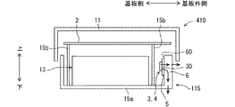
図13に示すように、第1パワー素子3は、回路基板2の直上に位置するように設置されている。したがって、第1パワー素子3の直下には、回路基板2が存在している。第1パワー素子3は、熱伝導性部材5を介して放熱部材406に間接的に接触した状態で設置されている。放熱部材406は、カバー11における天壁部の内面に熱移動可能な構成で設けられている。カバー11は、熱伝導性を有する材質で形成されており、ベースケース15のベース部15aに対して熱移動可能な構成で装着されている。第1パワー素子3の外装部30から熱伝導性部材5を通じて放熱部材406に移動した熱は、カバー11の天壁部に移動した後、天壁部から下方に延びる側壁部に伝わり、ベース部15aに移動した後、ブラケット70を介して車両部材7に移動することにより放出される。
As shown in FIG. 13, the
図14に示すように、第1パワー素子3の電力線部32は回路基板2には接続されておらず、ハーネス133を介して第1入出力端子140や第2入出力端子141に連結されており、信号線部31は回路基板2に接続されている。図14において破線で示すように、回路基板における外周縁の一部である端部20は、回路基板2よりも高い位置に存在する第1パワー素子3と重なる位置にある。換言すれば、第1パワー素子3の外周縁に一部であって基板側の第1端部30aは、回路基板2の直上となる位置に設けられ、第1端部30aとは反対側に位置する基板外側の第2端部30bは回路基板2の上方であって外側に位置するように設けられている。したがって、第1パワー素子3は、第1パワー素子3および回路基板2を平面視した場合に、第1パワー素子3において回路基板2と重なる重なり部分30cと第1パワー素子3において回路基板2と重ならない残部30dとを有するように設置されている。さらに、第1パワー素子3と回路基板2とは残部30dの体積が重なり部分30cの体積に対して同等または大きくなるような位置関係であることが好ましい。
As shown in FIG. 14, the
第6実施形態によれば、信号線部31が接続されている回路基板2と電力線部32との距離を確保できるので、回路基板2に対するノイズの影響を抑制することができるとともに、重なり部分30cを有することにより、電池装置210の小型化に寄与する。また、電力線部32を回路基板2よりも外側にはみ出させることにより、電力線部32とハーネス133との結合を行いやすい構成を提供できる。第1パワー素子3の熱は下方よりも上方の方が伝わりやすいため、第1パワー素子3の放熱性を高めることに寄与する。
According to the sixth embodiment, the distance between the
(第7実施形態)
第7実施形態では、第6実施形態の電池装置210を、車両部材7に対して縦置きに設置した状態である図15について説明する。図15において、前述の実施形態の図面中と同一符号を付した構成要素は、同様の構成要素であり、同様の作用効果を奏するものである。第7実施形態のように設置された電池装置210における第1パワー素子3から車両部材7に至る放熱経路は、第6実施形態と同様である。第7実施形態の電池装置210は、第6実施形態において前述した作用効果と同様の作用効果を奏する。
(Seventh embodiment)
In the seventh embodiment, FIG. 15 in which the
(第8実施形態)
第8実施形態では、第1実施形態の他の形態である電池装置310について図16を参照して説明する。図16において、第1実施形態の図面中と同一符号を付した構成要素は、同様の構成要素であり、同様の作用効果を奏するものである。電池装置310における第1パワー素子3や第2パワー素子4から車両部材7に至る放熱経路は、第1実施形態の電池装置10と同様である。電池装置310は、第1実施形態や第5実施形態の電池装置がもたらす作用効果と同様の作用効果を奏する。以下、第1実施形態および第5実施形態との相違点について説明する。
(Eighth embodiment)
In the eighth embodiment, a
図16に示すように、電池装置310が有する放熱部材6はベースケース115の一部分をなしている。放熱部材6はベースケース115の底部であるベース部15aから起立する立壁部をなしている。放熱部材6は、ベースケース115と同じ材質でできており、例えば、アルミニウム、銅、これらの合金によって形成されている。第1パワー素子3や第2パワー素子4は、外装部がベース部15aから起立する立壁部に直接または熱伝導性部材5を介して間接的に接触した状態で設置されている。また、第1パワー素子3、第2パワー素子4、放熱部材は、図16に示すように回路基板2に対して低い位置に離間して設置されているが、これに代えて回路基板2に対して高い位置に離間して設置されている構成としてもよい。
As shown in FIG. 16, the
第8実施形態の電池装置310によれば、放熱部材6はベースケース115の一部であってベース部15aから起立するように形成された立壁部である。この構成によれば、放熱部材6をベースケース115の一部分とするため、放熱部材6からベースケース115への熱移動の抵抗を抑えることができ、スイッチ装置の放熱性向上を図ることができる。放熱部材6は、ベースケース115の一部であってベース部15aから起立する立壁部であるため、この立壁部によってスイッチ装置が被水または浸水の状態になることを抑えることができる。また、組電池13を被水または浸水の状態から保護するための立壁部を、放熱部材6として活用することができ、電池装置310の小型化、部品点数の低減が図れる。
According to the
スイッチ装置の外装部は、放熱部材6である立壁部の上面に直接または熱伝導性部材5を介して間接的に接触している。この構成によれば、立壁部を利用して、スイッチ装置を高い位置に設置できるため、スイッチ装置が被水または浸水の状態になりにくい電池装置310を提供できる。
The exterior of the switch device is in direct contact with the upper surface of the upright wall, which is the
(第9実施形態)
第9実施形態では、第1実施形態の他の形態である電池装置410について図17を参照して説明する。図17において、第1実施形態の図面中と同一符号を付した構成要素は、同様の構成要素であり、同様の作用効果を奏するものである。電池装置410における第1パワー素子3や第2パワー素子4から車両部材7に至る放熱経路は、第1実施形態の電池装置10と同様である。電池装置410は、第1実施形態および第8実施形態の電池装置がもたらす作用効果と同様の作用効果を奏する。以下、第1実施形態および第8実施形態との相違点について説明する。
(Ninth embodiment)
In the ninth embodiment, a
図10に示すように、第1パワー素子3や第2パワー素子4は、厚さ方向が回路基板2の主面に対して沿うような姿勢で設置されており、ベース部15aから起立する立壁部をなす放熱部材6に熱伝導性部材5を介して間接的に接触している。第1パワー素子3や第2パワー素子4は、外装部から信号線部が突出する方向が回路基板2の主面に対して直交するような縦置き姿勢で放熱部材6に熱移動可能に接触している。第1パワー素子3や第2パワー素子4は、ベース部15aから起立する立壁部の側面60に設置されている。したがって、立壁部である放熱部材6は、第1パワー素子3との熱的な接続部分を上下方向に延びるとともに、組電池13に対向する内側の側面60を有している。
As shown in FIG. 10, the
また、第1パワー素子3の外装部30や第2パワー素子4の外装部は、立壁部に直接接触するように設置されている構成でもよい。また、第1パワー素子3、第2パワー素子4、放熱部材は、図17に示すように回路基板2に対して低い位置に離間して設置されているが、これに代えて回路基板2に対して高い位置に離間して設置されている構成としてもよい。
Further, the
以上の構成によれば、各パワー素子の外装部から熱伝導性部材5を通じて、放熱部材6である立壁部に移動した熱は、横方向に伝達して外側の側面から雰囲気に放出されるとともに、ベース部15aに移動後、ブラケット70を介して車両部材7に移動する。
According to the above configuration, the heat transferred from the exterior portion of each power element to the standing wall portion serving as the
第9実施形態によれば、スイッチ装置の外装部は、放熱部材6である立壁部の側面60に直接または熱伝導性部材5を介して間接的に接触している。この構成によれば、スイッチ装置の発熱を立壁部を通じて外部の雰囲気に放出できるとともに、ベース部15aを通じて車両部材7に放出することもできる。この2つの放熱経路によって放熱性を高めることができ、各放熱経路は短い経路を構成できる。
According to the ninth embodiment, the exterior of the switch device is in direct contact with the
第9実施形態の電池装置410によれば、スイッチ装置の厚さ方向を電池装置410の幅方向または横方向に向けてスイッチ装置を設置することにより、幅方向について電池装置410の体格を抑えることができる。
According to the
スイッチ装置の外装部は、放熱部材6である立壁部において組電池13寄りに位置する内側の側面60に直接または熱伝導性部材5を介して間接的に接触している。この構成によれば、外力からスイッチ装置を保護できるとともに、外部からの被水や浸水に対して立壁部が障壁になるため、スイッチ装置の防水効果を高めることができる。
The exterior part of the switch device is in direct contact with the
また、スイッチ装置の外装部は、放熱部材6である立壁部において外側に位置する側面に直接または熱伝導性部材5を介して間接的に接触している構成でもよい。
Further, the exterior of the switch device may be configured to directly or indirectly contact the side surface located on the outside of the upright wall, which is the
(他の実施形態)
この明細書の開示は、例示された実施形態に制限されない。開示は、例示された実施形態と、それらに基づく当業者による変形態様を包含する。例えば、開示は、実施形態において示された部品、要素の組み合わせに限定されず、種々変形して実施することが可能である。開示は、多様な組み合わせによって実施可能である。開示は、実施形態に追加可能な追加的な部分をもつことができる。開示は、実施形態の部品、要素が省略されたものを包含する。開示は、ひとつの実施形態と他の実施形態との間における部品、要素の置き換え、または組み合わせを包含する。開示される技術的範囲は、実施形態の記載に限定されない。開示される技術的範囲は、特許請求の範囲の記載によって示され、さらに特許請求の範囲の記載と均等の意味および範囲内での全ての変更を含むものと解されるべきである。
(Other embodiments)
The disclosure of this specification is not limited to the illustrated embodiments. The disclosure includes the illustrated embodiments and variations based thereon based on those skilled in the art. For example, the disclosure is not limited to the combination of the components and elements shown in the embodiment, and can be implemented with various modifications. The disclosure can be implemented in various combinations. The disclosure may have additional parts that can be added to the embodiments. The disclosure includes those in which the components and elements of the embodiments are omitted. The disclosure encompasses the replacement or combination of parts, elements between one embodiment and another. The disclosed technical scope is not limited to the description of the embodiments. The technical scope disclosed is indicated by the description of the claims, and should be construed to include all modifications within the meaning and scope equivalent to the description of the claims.
前述の実施形態におけるパワー素子は、半導体素子を有さない、電池に対する電力の入出力を制御するメカニカルリレーに置き換えることができる。メカニカルリレーは、例えばコイルと接点部を有し、接点部を閉じることにより電力の流通を許可する状態を実現して電力の入出力を制御するスイッチ装置である。メカニカルリレーの場合、その外装部は、例えば樹脂によって形成された直方体状のケースをなす。ケースの外部には、前述したように、信号線部31および電力線部32がそれぞれ突出している。このように特許請求の範囲で記載するスイッチ装置には、パワー素子、メカニカルリレー等が含まれる。
The power element in the above-described embodiment can be replaced with a mechanical relay having no semiconductor element and controlling input / output of electric power to / from a battery. The mechanical relay is a switch device that has, for example, a coil and a contact portion, and realizes a state in which the flow of power is permitted by closing the contact portion, and controls input and output of power. In the case of a mechanical relay, the exterior part forms a rectangular parallelepiped case formed of, for example, resin. As described above, the
前述の実施形態において、外部電池17、組電池13のそれぞれを構成する単電池は、第1実施形態で記載した鉛蓄電池、リチウムイオン二次電池の他、例えばニッケル水素二次電池、有機ラジカル電池で構成してもよい。
In the above-described embodiment, the unit cells constituting each of the
前述の実施形態において、パワー素子と回路基板2とは、平面視した場合に、部分的に重なる位置関係であることを説明したが、パワー素子と回路基板2はパワー素子の全部が回路基板2に重なる位置関係でもよい。また、パワー素子と回路基板2は全く重ならない位置関係でもよい。
In the above-described embodiment, it has been described that the power element and the
前述の実施形態において電池装置が備える単電池は、例えば、外装ケースが薄い平板状の形態をなし、外装ケースがラミネートシートで形成されている形態でもよい。ラミネートシートは、絶縁性の高い素材で構成されている。この場合、単電池は、例えば二つ折りにされたラミネートシートの端部同士を熱融着することにより当該端部同士を封止して密閉された扁平状容器の内部空間を有する。この内部空間には、電極集合体、電解質、端子接続部、正極端子部の一部、および負極端子部の一部を含む電池本体部が内蔵されている。したがって、単電池は、扁平状容器の周縁部が封止されることにより、電池本体部が扁平状容器の内部に密封状態で収容されている。単電池は、扁平状容器から外方へ引き出された一対の電極端子を有する。 In the above-described embodiment, the unit cell included in the battery device may have, for example, a form in which the outer case has a thin flat plate shape and the outer case is formed of a laminate sheet. The laminate sheet is made of a highly insulating material. In this case, the unit cell has, for example, an internal space of a flat container that is sealed by heat-sealing the ends of the folded laminate sheet to seal the ends. In this internal space, a battery main body including an electrode assembly, an electrolyte, a terminal connection part, a part of a positive electrode terminal part, and a part of a negative electrode terminal part is incorporated. Therefore, in the unit cell, the battery body is sealed in the flat container by sealing the peripheral portion of the flat container. The cell has a pair of electrode terminals that are drawn out of the flat container.
前述の実施形態において電池装置が備える単電池として、例えば、円柱状の外形形状である単電池を用いてもよい。 In the above-described embodiment, for example, a unit cell having a columnar outer shape may be used as the unit cell included in the battery device.
前述の実施形態において、電池装置が備える電池は1個または複数の単電池で構成することができる。複数の単電池は、上下方向に積層された形態でもよいし、横方向に並べて積層された形態でもよい。 In the above-described embodiment, the battery included in the battery device can be configured by one or a plurality of unit cells. The plurality of cells may be stacked in a vertical direction or stacked in a horizontal direction.
2…回路基板、 3…第1パワー素子(第1のスイッチ装置、スイッチ装置)
4…第2パワー素子(第2のスイッチ装置、スイッチ装置)
5…熱伝導性部材、 6,106,206,306,406…放熱部材
7…車両部材、 13…組電池(電池)、
13a…第1電池積層体(電池積層体)、 13b…第2電池積層体(電池積層体)
15…ベースケース、 15a…ベース部
30…外装部、 31…信号線部、 32…電力線部、 33…バスバ
70…ブラケット(装着部材)、 140…第1入出力端子(入出力端子)
141…第2入出力端子(入出力端子)
2.
4. Second power element (second switch device, switch device)
5: heat conductive member, 6, 106, 206, 306, 406: heat dissipating member 7: vehicle member, 13: assembled battery (battery),
13a: first battery laminate (battery laminate), 13b: second battery laminate (battery laminate)
DESCRIPTION OF
141 second input / output terminal (input / output terminal)
Claims (15)
前記電池に電気的に接続されている回路基板(2)と、
前記電池に対する電力の入出力を制御するスイッチ装置であって、外面を形成する外装部(30)が前記回路基板から離間した状態で設置されているスイッチ装置(3,4)と、
熱伝導性を有する材質によって形成されている放熱部材であって、前記スイッチ装置の熱が移動可能なように前記スイッチ装置の前記外装部に直接または熱伝導性部材(5)を介して間接的に接触している放熱部材(6,106,206,306,406)と、
前記スイッチ装置の外装部から前記放熱部材を介して、前記電池が収容されているベースケース(15)のベース部(15a)に熱伝達する伝熱経路と、
を備え、
前記回路基板は、前記放熱部材とは別個の部材であって前記ベース部から分岐するように延びる部材に固定されている電池装置。 A battery (13);
A circuit board (2) electrically connected to the battery;
A switch device for controlling the input and output of power to and from the battery, wherein the exterior device (30) forming an outer surface is installed in a state separated from the circuit board;
A heat dissipating member made of a material having thermal conductivity, wherein the heat dissipating member is directly or indirectly connected to the exterior portion of the switch device via a heat conductive member so that heat of the switch device can move. A heat dissipating member (6, 106, 206, 306, 406) in contact with
A heat transfer path for transferring heat from the exterior part of the switch device to the base part (15a) of the base case (15) containing the battery via the heat radiation member;
With
The battery device, wherein the circuit board is fixed to a member that is separate from the heat radiating member and extends so as to branch off from the base portion.
前記スイッチ装置は、厚さ方向が前記回路基板の主面に対して沿うような姿勢でまたは傾くような姿勢で設置されている請求項6または請求項7に記載の電池装置。
The switch device has an outer shape in which a width dimension of the exterior part is longer than a thickness dimension,
The switching device is battery device according to claim 6 or claim 7 or in position as the thickness direction along the principal surface of the circuit board that is installed in a posture tilted.
前記スイッチ装置は、前記電池に対して前記電極端子寄りに設置されている請求項1から請求項12のいずれか一項に記載の電池装置。 The battery Ri Contact is installed in a posture electrode terminals (130) are exposed laterally
The battery device according to any one of claims 1 to 12, wherein the switch device is provided near the electrode terminal with respect to the battery.
前記スイッチ装置は、複数の前記電池積層体のうち、前記単電池の積層数が少ない方の前記電池積層体(13a)寄りに設置されている請求項1から請求項13のいずれか一項に記載の電池装置。 The battery is constituted by a plurality of battery stacks (13a, 13b) in which a plurality of unit cells are stacked, respectively.
14. The switch device according to claim 1, wherein the switch device is disposed closer to the battery stack (13 a), where the number of stacked cells is smaller, among the plurality of battery stacks. 15. The battery device according to any one of the preceding claims.
Priority Applications (4)
| Application Number | Priority Date | Filing Date | Title |
|---|---|---|---|
| DE112017005209.2T DE112017005209B4 (en) | 2016-10-14 | 2017-10-04 | Battery device |
| PCT/JP2017/036054 WO2018070310A1 (en) | 2016-10-14 | 2017-10-04 | Battery device |
| US16/360,304 US11695282B2 (en) | 2016-10-14 | 2019-03-21 | Battery device |
| JP2019205068A JP6908091B2 (en) | 2016-10-14 | 2019-11-12 | Battery device |
Applications Claiming Priority (2)
| Application Number | Priority Date | Filing Date | Title |
|---|---|---|---|
| JP2016202937 | 2016-10-14 | ||
| JP2016202937 | 2016-10-14 |
Related Child Applications (2)
| Application Number | Title | Priority Date | Filing Date |
|---|---|---|---|
| JP2019205068A Division JP6908091B2 (en) | 2016-10-14 | 2019-11-12 | Battery device |
| JP2019205067A Division JP6766940B2 (en) | 2016-10-14 | 2019-11-12 | Battery device |
Publications (3)
| Publication Number | Publication Date |
|---|---|
| JP2018067533A JP2018067533A (en) | 2018-04-26 |
| JP2018067533A5 JP2018067533A5 (en) | 2018-10-25 |
| JP6638710B2 true JP6638710B2 (en) | 2020-01-29 |
Family
ID=62087264
Family Applications (3)
| Application Number | Title | Priority Date | Filing Date |
|---|---|---|---|
| JP2017179311A Active JP6638710B2 (en) | 2016-10-14 | 2017-09-19 | Battery device |
| JP2019205068A Active JP6908091B2 (en) | 2016-10-14 | 2019-11-12 | Battery device |
| JP2019205067A Active JP6766940B2 (en) | 2016-10-14 | 2019-11-12 | Battery device |
Family Applications After (2)
| Application Number | Title | Priority Date | Filing Date |
|---|---|---|---|
| JP2019205068A Active JP6908091B2 (en) | 2016-10-14 | 2019-11-12 | Battery device |
| JP2019205067A Active JP6766940B2 (en) | 2016-10-14 | 2019-11-12 | Battery device |
Country Status (3)
| Country | Link |
|---|---|
| US (1) | US11695282B2 (en) |
| JP (3) | JP6638710B2 (en) |
| DE (1) | DE112017005209B4 (en) |
Families Citing this family (9)
| Publication number | Priority date | Publication date | Assignee | Title |
|---|---|---|---|---|
| JP6652030B2 (en) * | 2016-10-14 | 2020-02-19 | 株式会社デンソー | Battery device |
| JP6988399B2 (en) * | 2016-12-05 | 2022-01-05 | トヨタ自動車株式会社 | In-vehicle battery relay connection structure |
| JP7013745B2 (en) | 2017-09-12 | 2022-02-15 | 株式会社デンソー | Battery pack |
| JP7135425B2 (en) * | 2018-05-14 | 2022-09-13 | 株式会社デンソー | battery pack |
| JP7119953B2 (en) * | 2018-11-28 | 2022-08-17 | 株式会社デンソー | battery pack |
| JP7230724B2 (en) * | 2019-07-25 | 2023-03-01 | 株式会社デンソー | battery unit |
| JP6943303B2 (en) | 2020-02-12 | 2021-09-29 | ダイキン工業株式会社 | Program and control method |
| DE102020206338A1 (en) | 2020-05-20 | 2021-11-25 | Robert Bosch Gesellschaft mit beschränkter Haftung | Battery module with a plurality of battery cells |
| CN115621649B (en) * | 2022-11-08 | 2023-04-14 | 广东顺德电力设计院有限公司 | Electric automobile energy storage management control device |
Family Cites Families (24)
| Publication number | Priority date | Publication date | Assignee | Title |
|---|---|---|---|---|
| JP2005316861A (en) | 2004-04-30 | 2005-11-10 | Hitachi Ltd | Disk array device |
| KR100904373B1 (en) * | 2004-12-24 | 2009-06-25 | 주식회사 엘지화학 | Heat Radiation Structure for Secondary Battery Module, and Switching Board And Secondary Battery Module Having the Same |
| US7978031B2 (en) | 2008-01-31 | 2011-07-12 | Tdk Corporation | High frequency module provided with power amplifier |
| JP4492708B2 (en) | 2008-01-31 | 2010-06-30 | Tdk株式会社 | High frequency module |
| JP2010009990A (en) | 2008-06-27 | 2010-01-14 | Sanyo Electric Co Ltd | Vehicular power supply device |
| US8547068B2 (en) * | 2008-09-18 | 2013-10-01 | Samsung Sdi Co., Ltd. | Protection circuit module and secondary battery including the protection circuit module |
| JP2011154986A (en) * | 2010-01-28 | 2011-08-11 | Sanyo Electric Co Ltd | Battery pack |
| JP5825264B2 (en) | 2011-01-21 | 2015-12-02 | 株式会社Gsユアサ | Battery system |
| JP5672218B2 (en) * | 2011-11-23 | 2015-02-18 | 株式会社デンソー | Assembled battery |
| US20130143079A1 (en) | 2011-12-02 | 2013-06-06 | Golden Crown New Energy (Hk) Limited | Battery system with heat-dissipation improvement and connecting circuit arrangement |
| JP5241910B2 (en) | 2011-12-22 | 2013-07-17 | 太陽誘電株式会社 | Circuit board |
| JP5942644B2 (en) | 2012-07-05 | 2016-06-29 | 株式会社デンソー | Battery unit |
| JP6015174B2 (en) * | 2012-07-05 | 2016-10-26 | 株式会社デンソー | Battery unit |
| JP2016012389A (en) * | 2012-10-29 | 2016-01-21 | 三洋電機株式会社 | Power unit and vehicle with power unit |
| JP2014089839A (en) * | 2012-10-29 | 2014-05-15 | Sanyo Electric Co Ltd | Power supply device and vehicle having the same |
| WO2014068897A1 (en) * | 2012-10-29 | 2014-05-08 | 三洋電機株式会社 | Power supply device, vehicle and power storage device provided with power supply device, and battery system |
| US20150343919A1 (en) * | 2012-10-29 | 2015-12-03 | Sanyo Electric Co., Ltd. | Vehicle-mounted power supply device and vehicle comprising power supply device |
| JPWO2014068899A1 (en) * | 2012-10-29 | 2016-09-08 | 三洋電機株式会社 | Power supply device, vehicle including power supply device, power storage device, and battery system |
| JP6105358B2 (en) | 2013-04-02 | 2017-03-29 | 太陽誘電株式会社 | Circuit board |
| JP6094452B2 (en) * | 2013-10-23 | 2017-03-15 | 株式会社オートネットワーク技術研究所 | Power storage module |
| JP2015088380A (en) * | 2013-10-31 | 2015-05-07 | 日立マクセル株式会社 | Battery pack |
| JP2015153719A (en) | 2014-02-19 | 2015-08-24 | 株式会社東芝 | Power supply system, and vehicle |
| JP2017179311A (en) | 2016-03-31 | 2017-10-05 | 日立化成株式会社 | Resin composition, prepreg, resin sheet and laminate |
| JP2016202937A (en) | 2016-07-07 | 2016-12-08 | ニプロ株式会社 | Needleless connector |
-
2017
- 2017-09-19 JP JP2017179311A patent/JP6638710B2/en active Active
- 2017-10-04 DE DE112017005209.2T patent/DE112017005209B4/en active Active
-
2019
- 2019-03-21 US US16/360,304 patent/US11695282B2/en active Active
- 2019-11-12 JP JP2019205068A patent/JP6908091B2/en active Active
- 2019-11-12 JP JP2019205067A patent/JP6766940B2/en active Active
Also Published As
| Publication number | Publication date |
|---|---|
| JP2020021751A (en) | 2020-02-06 |
| JP6766940B2 (en) | 2020-10-14 |
| DE112017005209B4 (en) | 2024-02-15 |
| JP6908091B2 (en) | 2021-07-21 |
| US20190221906A1 (en) | 2019-07-18 |
| JP2020021752A (en) | 2020-02-06 |
| US11695282B2 (en) | 2023-07-04 |
| DE112017005209T5 (en) | 2019-08-01 |
| JP2018067533A (en) | 2018-04-26 |
Similar Documents
| Publication | Publication Date | Title |
|---|---|---|
| JP6638710B2 (en) | Battery device | |
| JP6528007B2 (en) | Battery cell cooling bus bar and battery module using the same | |
| JP6652030B2 (en) | Battery device | |
| JP6627709B2 (en) | Battery device | |
| JP6138688B2 (en) | Power supply device, vehicle including the same, and power storage device | |
| WO2013161654A1 (en) | Power-supply device, vehicle provided with power-supply device, and electricity-storage device | |
| JP6589952B2 (en) | Connection member, electrical component unit, and battery device | |
| WO2013031614A1 (en) | Power supply device, vehicle provided with same, and power storage device | |
| JP2012033419A (en) | Power supply device, vehicle using the same, battery cell, and method of manufacturing the battery cell | |
| JP6724846B2 (en) | Heat dissipation device for battery pack and bus bar | |
| JP6720847B2 (en) | Battery pack | |
| CN112042102B (en) | power conversion device | |
| JPWO2014068897A1 (en) | Power supply device, vehicle including power supply device, power storage device, and battery system | |
| US11557802B2 (en) | Vehicle battery pack | |
| JP6904045B2 (en) | Battery pack | |
| JP5022316B2 (en) | Secondary battery device | |
| JP6291847B2 (en) | Battery cooling device | |
| US20220418085A1 (en) | Circuit structure | |
| WO2018070310A1 (en) | Battery device | |
| JP6311591B2 (en) | Battery unit | |
| WO2018070309A1 (en) | Connection member, electric component unit, and battery device | |
| JP2018032520A (en) | Power storage device | |
| JP6015573B2 (en) | Cooling system | |
| JP6805792B2 (en) | Battery pack | |
| JP6144128B2 (en) | Battery for vehicle |
Legal Events
| Date | Code | Title | Description |
|---|---|---|---|
| A521 | Request for written amendment filed |
Free format text: JAPANESE INTERMEDIATE CODE: A523 Effective date: 20171010 |
|
| AA64 | Notification of invalidation of claim of internal priority (with term) |
Free format text: JAPANESE INTERMEDIATE CODE: A241764 Effective date: 20171010 |
|
| A521 | Request for written amendment filed |
Free format text: JAPANESE INTERMEDIATE CODE: A523 Effective date: 20180911 |
|
| A621 | Written request for application examination |
Free format text: JAPANESE INTERMEDIATE CODE: A621 Effective date: 20180911 |
|
| A131 | Notification of reasons for refusal |
Free format text: JAPANESE INTERMEDIATE CODE: A131 Effective date: 20190917 |
|
| A521 | Request for written amendment filed |
Free format text: JAPANESE INTERMEDIATE CODE: A523 Effective date: 20191112 |
|
| TRDD | Decision of grant or rejection written | ||
| A01 | Written decision to grant a patent or to grant a registration (utility model) |
Free format text: JAPANESE INTERMEDIATE CODE: A01 Effective date: 20191126 |
|
| A61 | First payment of annual fees (during grant procedure) |
Free format text: JAPANESE INTERMEDIATE CODE: A61 Effective date: 20191209 |
|
| R151 | Written notification of patent or utility model registration |
Ref document number: 6638710 Country of ref document: JP Free format text: JAPANESE INTERMEDIATE CODE: R151 |
|
| R250 | Receipt of annual fees |
Free format text: JAPANESE INTERMEDIATE CODE: R250 |
|
| R250 | Receipt of annual fees |
Free format text: JAPANESE INTERMEDIATE CODE: R250 |