JP6638535B2 - Network control device and transmission quality margin calculation method - Google Patents
Network control device and transmission quality margin calculation method Download PDFInfo
- Publication number
- JP6638535B2 JP6638535B2 JP2016083995A JP2016083995A JP6638535B2 JP 6638535 B2 JP6638535 B2 JP 6638535B2 JP 2016083995 A JP2016083995 A JP 2016083995A JP 2016083995 A JP2016083995 A JP 2016083995A JP 6638535 B2 JP6638535 B2 JP 6638535B2
- Authority
- JP
- Japan
- Prior art keywords
- osnr
- ber
- noise intensity
- margin
- node
- Prior art date
- Legal status (The legal status is an assumption and is not a legal conclusion. Google has not performed a legal analysis and makes no representation as to the accuracy of the status listed.)
- Active
Links
- 230000005540 biological transmission Effects 0.000 title claims description 87
- 238000004364 calculation method Methods 0.000 title claims description 77
- 238000012937 correction Methods 0.000 claims description 66
- 238000004891 communication Methods 0.000 claims description 14
- 238000000034 method Methods 0.000 claims description 12
- 238000010586 diagram Methods 0.000 description 56
- 230000003287 optical effect Effects 0.000 description 36
- 238000012545 processing Methods 0.000 description 13
- 230000006870 function Effects 0.000 description 5
- 238000005259 measurement Methods 0.000 description 5
- 239000013307 optical fiber Substances 0.000 description 4
- 238000001228 spectrum Methods 0.000 description 4
- 238000013461 design Methods 0.000 description 3
- 239000000835 fiber Substances 0.000 description 2
- 238000012544 monitoring process Methods 0.000 description 2
- 230000010363 phase shift Effects 0.000 description 2
- 230000002269 spontaneous effect Effects 0.000 description 2
- 238000005516 engineering process Methods 0.000 description 1
- 230000010354 integration Effects 0.000 description 1
Images


Classifications
-
- H—ELECTRICITY
- H04—ELECTRIC COMMUNICATION TECHNIQUE
- H04B—TRANSMISSION
- H04B10/00—Transmission systems employing electromagnetic waves other than radio-waves, e.g. infrared, visible or ultraviolet light, or employing corpuscular radiation, e.g. quantum communication
- H04B10/07—Arrangements for monitoring or testing transmission systems; Arrangements for fault measurement of transmission systems
- H04B10/075—Arrangements for monitoring or testing transmission systems; Arrangements for fault measurement of transmission systems using an in-service signal
- H04B10/079—Arrangements for monitoring or testing transmission systems; Arrangements for fault measurement of transmission systems using an in-service signal using measurements of the data signal
- H04B10/0795—Performance monitoring; Measurement of transmission parameters
- H04B10/07953—Monitoring or measuring OSNR, BER or Q
-
- H—ELECTRICITY
- H04—ELECTRIC COMMUNICATION TECHNIQUE
- H04B—TRANSMISSION
- H04B10/00—Transmission systems employing electromagnetic waves other than radio-waves, e.g. infrared, visible or ultraviolet light, or employing corpuscular radiation, e.g. quantum communication
- H04B10/07—Arrangements for monitoring or testing transmission systems; Arrangements for fault measurement of transmission systems
- H04B10/075—Arrangements for monitoring or testing transmission systems; Arrangements for fault measurement of transmission systems using an in-service signal
- H04B10/079—Arrangements for monitoring or testing transmission systems; Arrangements for fault measurement of transmission systems using an in-service signal using measurements of the data signal
- H04B10/0793—Network aspects, e.g. central monitoring of transmission parameters
-
- H—ELECTRICITY
- H04—ELECTRIC COMMUNICATION TECHNIQUE
- H04B—TRANSMISSION
- H04B10/00—Transmission systems employing electromagnetic waves other than radio-waves, e.g. infrared, visible or ultraviolet light, or employing corpuscular radiation, e.g. quantum communication
- H04B10/07—Arrangements for monitoring or testing transmission systems; Arrangements for fault measurement of transmission systems
- H04B10/075—Arrangements for monitoring or testing transmission systems; Arrangements for fault measurement of transmission systems using an in-service signal
- H04B10/079—Arrangements for monitoring or testing transmission systems; Arrangements for fault measurement of transmission systems using an in-service signal using measurements of the data signal
- H04B10/0795—Performance monitoring; Measurement of transmission parameters
- H04B10/07955—Monitoring or measuring power
-
- H—ELECTRICITY
- H04—ELECTRIC COMMUNICATION TECHNIQUE
- H04B—TRANSMISSION
- H04B10/00—Transmission systems employing electromagnetic waves other than radio-waves, e.g. infrared, visible or ultraviolet light, or employing corpuscular radiation, e.g. quantum communication
- H04B10/07—Arrangements for monitoring or testing transmission systems; Arrangements for fault measurement of transmission systems
- H04B10/075—Arrangements for monitoring or testing transmission systems; Arrangements for fault measurement of transmission systems using an in-service signal
- H04B10/079—Arrangements for monitoring or testing transmission systems; Arrangements for fault measurement of transmission systems using an in-service signal using measurements of the data signal
- H04B10/0795—Performance monitoring; Measurement of transmission parameters
- H04B10/07957—Monitoring or measuring wavelength
-
- H—ELECTRICITY
- H04—ELECTRIC COMMUNICATION TECHNIQUE
- H04J—MULTIPLEX COMMUNICATION
- H04J14/00—Optical multiplex systems
- H04J14/02—Wavelength-division multiplex systems
-
- H—ELECTRICITY
- H04—ELECTRIC COMMUNICATION TECHNIQUE
- H04L—TRANSMISSION OF DIGITAL INFORMATION, e.g. TELEGRAPHIC COMMUNICATION
- H04L1/00—Arrangements for detecting or preventing errors in the information received
- H04L1/24—Testing correct operation
- H04L1/242—Testing correct operation by comparing a transmitted test signal with a locally generated replica
- H04L1/243—Testing correct operation by comparing a transmitted test signal with a locally generated replica at the transmitter, using a loop-back
Description
本発明は、ネットワーク制御装置及び伝送品質マージン算出方法に関する。 The present invention relates to a network control device and a transmission quality margin calculation method.
光通信ネットワークのシステム設計は、予め設定された、例えば、ファイバパラメータ、信号変調フォーマット、ビットレートやファイバ入力光パワー等のシステム条件に基づき、通信サービスの運用前に行われる。 The system design of the optical communication network is performed before the operation of the communication service based on preset system conditions such as a fiber parameter, a signal modulation format, a bit rate, and a fiber input optical power.
高密度な波長多重信号光を伝送するシステムでは、伝送中の波長信号同士の干渉によるペナルティを考慮する他、運用中の動的なパスの切替や波長増設、変調方式の変更に対応する事前設計が求められる。しかしながら、事前設計では、マージンが過剰になると、システム全体の伝送距離や伝送品質が低下する場合もある。そこで、必要最小限にマージンを抑えたシステムの運用及び、動的な光ネットワークの運用が求められているのが実情である。 In systems that transmit high-density wavelength-division multiplexed signal light, in addition to taking into account the penalty due to interference between wavelength signals being transmitted, advance design that supports dynamic path switching, wavelength expansion, and modulation method changes during operation Is required. However, in the pre-design, if the margin becomes excessive, the transmission distance and transmission quality of the entire system may be reduced. Therefore, it is a fact that there is a demand for operation of a system with a minimum required margin and operation of a dynamic optical network.
そこで、システム内の光伝送装置毎にEVM(Error Vector Magnitude)を測定し、その測定結果からESNR(Electrical Signal to Noise Ratio)を取得する。更に、取得したESNRからOSNR(Optical Signal to Noise Ratio)を算出し、そのOSNRに基づき、OSNRマージンを算出する方法が知られている。 Therefore, an EVM (Error Vector Magnitude) is measured for each optical transmission device in the system, and an ESNR (Electrical Signal to Noise Ratio) is obtained from the measurement result. Further, a method is known in which an OSNR (Optical Signal to Noise Ratio) is calculated from the acquired ESNR, and an OSNR margin is calculated based on the OSNR.
しかしながら、EVMを測定する機能を内蔵していない光伝送装置を用いる場合も想定され、EVMを測定できない可能性もあるため、この場合に課題となる。従って、伝送品質のマージンを精度よく推定できないのが実情である。 However, it is also assumed that an optical transmission device that does not have a function of measuring the EVM is used, and there is a possibility that the EVM cannot be measured. Therefore, the fact is that the transmission quality margin cannot be accurately estimated.
一つの側面では、伝送品質のマージンを精度よく算出できるネットワーク制御装置及び伝送品質マージン算出方法を提供することを目的とする。 An object of one aspect is to provide a network control device and a transmission quality margin calculation method that can accurately calculate a transmission quality margin.
一つの案のネットワーク制御装置は、第1の演算部と、第2の演算部と、第3の演算部と、第4の演算部と、算出部とを有する。第1の演算部は、波長信号を送信する送信端のノード内の折り返しの送信端のOSNR−BER特性から許容限界BER対応の第1のOSNRを算出する。第2の演算部は、前記波長信号を受信する受信端のノードの受信BERを取得し、前記送信端のOSNR−BER特性から前記受信BER対応の第2のOSNRを算出する。第3の演算部は、前記第1のOSNRから前記許容限界BER対応の第1の雑音強度を算出する。第4の演算部は、前記第2のOSNRから前記受信BER対応の第2の雑音強度を算出する。算出部は、前記第1の雑音強度及び前記第2の雑音強度に基づき、雑音強度マージンを算出する。 One proposed network control device includes a first operation unit, a second operation unit, a third operation unit, a fourth operation unit, and a calculation unit. The first calculation unit calculates a first OSNR corresponding to the permissible limit BER from the OSNR-BER characteristic of the loopback transmitting end in the transmitting end node transmitting the wavelength signal. The second arithmetic unit acquires a reception BER of a node at a reception end that receives the wavelength signal, and calculates a second OSNR corresponding to the reception BER from an OSNR-BER characteristic of the transmission end. The third calculation unit calculates a first noise intensity corresponding to the permissible limit BER from the first OSNR. The fourth calculation unit calculates a second noise intensity corresponding to the received BER from the second OSNR. The calculation unit calculates a noise intensity margin based on the first noise intensity and the second noise intensity.
一つの側面では、伝送品質のマージンを精度よく算出できる。 In one aspect, a margin of transmission quality can be calculated with high accuracy.
以下、図面に基づいて、本願の開示するネットワーク制御装置及び伝送品質マージン算出方法の実施例を詳細に説明する。尚、本実施例により、開示技術が限定されるものではない。また、以下に示す各実施例は、矛盾を起こさない範囲で適宜組み合わせても良い。 Hereinafter, embodiments of a network control device and a transmission quality margin calculation method disclosed in the present application will be described in detail with reference to the drawings. Note that the disclosed technology is not limited by the present embodiment. Further, the respective embodiments described below may be appropriately combined within a range that does not cause inconsistency.
図1は、実施例1の光伝送システム1の一例を示す説明図である。図1に示す光伝送システム1は、複数台のノード2と、ネットワーク(NW)制御装置3とを有する。各ノード2は、光ファイバ4で通信接続する、例えば、ノード“A”〜ノード“G”の7台の光伝送装置である。ノード2は、例えば、CD(Color-less Direction-less)のROADM(Reconfigurable Optical Add-Drop Multiplexer)又はCDC(Color-less Direction-less Contention-less)のROADMである。尚、説明の便宜上、ノード2の台数を7台としたが、これらに限定されるものではなく、その台数は適宜変更可能である。光伝送システム1は、例えば、複数の光波長パスを多重化する波長多重光伝送システムである。
FIG. 1 is an explanatory diagram illustrating an example of the
NW制御装置3は、光伝送システム1内の各ノード2の信号品質等の各種情報を収集する装置である。NW制御装置3は、運用中のBER(Bit Error Rate)からASE(Amplified Spontaneous Emission)雑音マージンを算出する装置である。
The
図2は、実施例1のノード2のハードウェア構成の一例を示す説明図である。図2に示すノード2は、入力アンプ11と、出力アンプ12と、複数の受信部(Rx)13と、複数の送信部(Tx)14と、光分岐挿入部15と、BER取得部16と、ノード制御部17とを有する。入力アンプ11は、光ファイバ4から入力する光信号を増幅する光アンプである。出力アンプ12は、光ファイバ4に出力する光信号を増幅する光アンプである。Rx13は、光信号を受信する受信部である。Tx14は、光信号を送信する送信部である。光分岐挿入部15は、波長パスを疎通する光信号の一部を光分岐すると共に、波長パスを疎通する光信号に新たな光信号を光挿入する機能と、波長パスを疎通する光信号のパワーを調整する機能とを有する。光分岐挿入部15は、光信号を光分岐し、光分岐した光信号を所定のRx13に伝送する。光分岐挿入部15は、光信号にTx14からの光信号を光挿入し、光挿入した光信号を出力アンプ12経由で光ファイバ4に出力する。
FIG. 2 is an explanatory diagram illustrating an example of a hardware configuration of the
BER取得部16は、Rx13にて受信パスのBERを測定する。ノード制御部17は、NW制御装置3と通信接続し、Rx13にて波長パスのBERを測定し、そのBERの測定結果を含む情報をNW制御装置3に通知する。尚、情報は、波長パスを識別するパス識別情報や、波長パスのBER等を含む。
The
図3は、実施例1のNW制御装置3の一例を示す説明図である。図3に示すNW制御装置3は、通信部21と、格納部22と、第1のマージン演算部23と、制御部24とを有する。通信部21は、各ノード2との間で通信する通信インタフェースである。格納部22は、各種情報を記憶する領域である。格納部22は、第1の格納部31と、第2の格納部32とを有する。第1の格納部31は、OSNRとBERとを対応付けて送信端OSNR耐力曲線を管理する格納部である。尚、送信端OSNR耐力曲線は、“A”の送信端ノード2内のTx14及びRx13との間の折り返し通信、すなわちBtoBのBERとOSNRとの対応関係を示す曲線である。第2の格納部32は、Tx特性のパラメータη及びκを格納する領域である。第1のマージン演算部23は、送信端OSNR耐力曲線及び運用中の受信BERmeaからASE(Amplified Spontaneous Emission)雑音マージンPase marginを算出する。尚、受信BERは、“A”の送信端ノード2から“C”の波長信号を受信する受信端ノード2で測定した実測のBERである。制御部24は、NW制御装置3全体を制御する。
FIG. 3 is an explanatory diagram illustrating an example of the
図4は、第1のマージン演算部23の一例を示す説明図である。図4に示す第1のマージン演算部23は、伝送条件メモリ41と、設定BERメモリ42と、第1の演算部43と、第2の演算部44と、第3の演算部45と、第4の演算部46と、算出部47とを有する。伝送条件メモリ41は、雑音の帯域幅Bnと、信号シンボルレートRsとを格納している。設定BERメモリ42は、光伝送システム1の許容限界のBERFECを格納している。尚、許容限界のBERFECは、光伝送システム1として許容できる限界のBERである。
FIG. 4 is an explanatory diagram illustrating an example of the first
第1の演算部43は、雑音の帯域幅Bnと、信号シンボルレートRsと、許容限界のBERFECとを数式1に代入してOSNRtotal FECを算出する。尚、数式1は、変調方式がQPSK(四位相偏移変調)の場合である。
The

第2の演算部44は、雑音の帯域幅Bnと、信号シンボルレートRsと、受信BERmeaとを数式2に代入してOSNRtotal meaを算出する。尚、数式2も、変調方式がQPSK(四位相偏移変調)の場合である。
The second
第3の演算部45は、第1の演算部43からのOSNRtotal FEC、Tx特性のパラメータη及びκを数式3に代入してASE雑音強度Pase FEC BtoBを算出する。尚、ASE雑音強度Pase FEC BtoBは、運用中のASE雑音強度Pase FEC trans及び非線形雑音強度PNLIの関係で数式4が成立する。
The
![]()
![]()
第4の演算部46は、第2の演算部44からのOSNRtotal mea、Tx特性のパラメータη及びκを数式5に代入してASE雑音強度Pase mea BtoBを算出する。尚、ASE雑音強度Pase mea BtoBは、運用中のASE雑音強度Pase mea trans及び非線形雑音強度PNLIの関係で数式6が成立する。
The
![]()
![]()
![]()
![]()
算出部47は、第3の演算部45で算出したASE雑音強度Pase FEC BtoBから第4の演算部46で算出したASE雑音強度Pase mea BtoBを減算し、その減算結果をASE雑音マージンPase marginとして算出する。尚、ASE雑音マージンPase marginは、数式7が成立し、その結果、数式8となる。
The
![]()
![]()
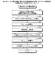
次に実施例1のNW制御装置3の動作について説明する。図5は、第1のマージン算出処理に関わるNW制御装置3内の第1のマージン演算部23の処理動作の一例を示すフローチャートである。
Next, the operation of the
図5において第1のマージン演算部23は、第1の格納部31から送信端OSNR耐力曲線及び、第2の格納部32からTx特性パラメータη及びκを取得する(ステップS11)。図6は、BER−OSNR特性上の送信端OSNR耐力曲線の一例を示す説明図である。尚、BER−OSNR特性は、縦軸をBER、横軸をOSNRとしている。図6に示す特性では、送信端OSNR耐力曲線及びBERFECを示している。
In FIG. 5, the first
第1のマージン演算部23内の第1の演算部43は、設定BERメモリ42から許容限界のBERFECを読み出し、数式1に基づき、雑音の帯域幅Bnと、信号シンボルレートRsと、BERFECとを数式1に代入する。そして、第1の演算部43は、BERFECに対応するOSNRtotal FECを算出する(ステップS12)。図7は、BER−OSNR特性上のBERFEC対応のOSNRtotal FECの一例を示す説明図である。図7に示すPsig/Pase FEC BtoBは、BERFEC対応のOSNRtotal FECである。
第1のマージン演算部23内の第3の演算部45は、OSNRtotal FECからASE雑音強度Pase FEC BtoBを算出する(ステップS13)。
The
第1のマージン演算部23内の第2の演算部44は、受信端ノード2の運用中の受信BERmeaを取得する(ステップS14)。尚、受信端ノード2の受信BERmeaは、受信端ノード2で測定された運用中の受信BERである。図8は、BER−OSNR特性上の運用中の受信BERmeaの一例を示す説明図である。図8に示す特性では、運用中の受信BERmeaを示している。
The second calculating
第2の演算部44は、雑音の帯域幅Bnと、信号シンボルレートRsと、受信BERmeaとを数式2に代入して、運用中の受信BERmeaに対応するOSNRtotal meaを算出する(ステップS15)。
Second
第1のマージン演算部23内の第4の演算部46は、第2の演算部44からのOSNRtotal mea、Tx特性のパラメータη及びκを数式5に代入してASE雑音強度Pase mea BtoBを算出する(ステップS16)。図9は、BER−OSNR特性上の受信BERmea対応のOSNRtotal meaの一例を示す説明図である。図9に示すPsig/Pase mea BtoBは、BERmea対応のOSNRtotal meaである。
The
第1のマージン演算部23内の算出部47は、ASE雑音強度Pase FEC BtoB及びASE雑音強度Pase mea BtoBに基づき、ASE雑音マージンPase marginを算出し(ステップS17)、図5に示す処理動作を終了する。図10は、BER−OSNR特性上の運用中のASE雑音マージンPase marginの一例を示す説明図である。図10に示す特性では、ASE雑音マージンPase marginを示している。受信端OSNR耐力曲線は、運用中の受信端のノード2のBER−OSNR特性の曲線である。
The
実施例1のNW制御装置3は、送信端OSNR耐力曲線から許容限界BERFECに対応するOSNRtotal FECを算出すると共に、送信端OSNR耐力曲線から受信BERmeaに対応するOSNRtotal meaを算出する。NW制御装置3は、OSNRtotal FECからASE雑音強度Pase FEC BtoBを算出すると共に、OSNRtotal meaからASE雑音強度Pase mea BtoBを算出する。NW制御装置3は、ASE雑音強度Pase FEC BtoBからASE雑音強度Pase mea BtoBを減算し、その減算結果をASE雑音マージンPase marginとして算出する。その結果、受信BERからASE雑音マージンを精度よく算出できる。
The
尚、上記実施例1のNW制御装置3は、受信端ノード2から運用中の受信BERmeaを取得したが、受信端ノード2から運用中の受信BERmeaの他に、受信OSNRを取得する場合の実施の形態につき、実施例2として以下に説明する。尚、実施例1の光伝送システム1と同一の構成には同一符号を付すことで、その重複する構成及び動作の説明については省略する。
Incidentally,
図11は、実施例2のノード2Aのハードウェア構成の一例を示すブロック図である。図11に示すノード2Aと図2に示すノード2とが異なるところは、OSNRモニタ18を内蔵した点にある。ノード2Aは、BER取得部16で受信端の受信BERmeaを取得すると共に、OSNRモニタ18で受信端の受信OSNR1を取得する。更に、ノード制御部17は、これら取得した受信端ノード2Aの受信BERmea及び受信端ノード2Aの受信OSNR1をNW制御装置3Aに通知する。
FIG. 11 is a block diagram illustrating an example of a hardware configuration of the
図12は、実施例2のNW制御装置3Aの一例を示す説明図である。図12に示すNW制御装置3Aと図3に示すNW制御装置3とが異なるところは、受信端ノード2Aから取得した受信BERmea及び受信端ノード2Aの受信OSNR1に基づきOSNRマージンOSNRmarginを算出する第2のマージン演算部23Aを有する点にある。
FIG. 12 is an explanatory diagram illustrating an example of the
図13は、第2のマージン演算部23Aの一例を示す説明図である。図13に示す第2のマージン演算部23Aは、第5の演算部48と、第6の演算部49と、第1の算出部50と、第2の算出部51と、第3の算出部52とを追加する。
FIG. 13 is an explanatory diagram illustrating an example of the second
第5の演算部48は、受信OSNR1を取得し、取得した受信OSNR1を数式9に代入してASE雑音強度Pase mea transを算出する。
Fifth
![]()
![]()
第1の算出部50は、数式10に基づき、第5の演算部48で算出したASE雑音強度Pase mea transから第4の演算部46で算出したASE雑音強度Pase mea BtoBを減算し、非線形雑音強度PNLIを算出する。第1の算出部50は、その算出した非線形雑音強度PNLIを第2の算出部51に入力する。
The
第2の算出部51は、第3の演算部45で算出したASE雑音強度Pase FEC BtoBから第1の算出部50で算出した非線形雑音強度PNLIを減算し、ASE雑音強度Pase FEC transを算出する。更に、第2の算出部51は、算出したASE雑音強度Pase FEC transを第6の演算部49に入力する。第6の演算部49は、ASE雑音強度Pase FEC transから運用中の設定BERFECに対応するOSNR2を算出し、算出したOSNR2を第3の算出部52に入力する。
The
第3の算出部52は、数式11に基づき、第5の演算部48で算出した受信OSNR1から第6の演算部49で算出したOSNR2を減算し、OSNRマージンOSNRmarginを算出する。第3の算出部52は、算出したOSNRmarginを制御部24に入力する。
![]()
![]()
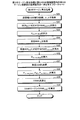
次に実施例2のNW制御装置3Aの動作について説明する。図14は、第2のマージン算出処理に関わるNW制御装置3A内の第2のマージン演算部23Aの処理動作の一例を示すフローチャートである。
Next, the operation of the
図14において第2のマージン演算部23Aは、第1の格納部31から送信端OSNR耐力曲線及び、第2の格納部32からTx特性パラメータη及びκを取得する(ステップS21)。第2のマージン演算部23A内の第1の演算部43は、設定BERメモリ42からBERFECを読み出し、数式1に基づき、雑音の帯域幅Bnと、信号シンボルレートRsと、BERFECとを数式1に代入する。そして、第1の演算部43は、BERFECに対応するOSNRtotal FECを算出する(ステップS22)。
In FIG. 14, the second
第2のマージン演算部23A内の第3の演算部45は、OSNRtotal FECからASE雑音強度Pase FEC BtoBを算出する(ステップS23)。第2のマージン演算部23A内の第2の演算部44は、受信端ノード2の運用中の受信BERmeaを取得する(ステップS24)。第2の演算部44は、雑音の帯域幅Bnと、信号シンボルレートRsと、受信BERmeaとを数式2に代入して、運用中の受信BERmeaに対応するOSNRtotal meaを算出する(ステップS25)。更に、第2のマージン演算部23A内の第4の演算部46は、OSNRtotal meaからASE雑音強度Pase mea BtoBを算出する(ステップS26)。
The
第2のマージン演算部23A内の第5の演算部48は、受信端ノード2の受信OSNR1を取得する(ステップS27)。図15は、BER−OSNR特性上の運用中の受信OSNR1の一例を示す説明図である。図15に示す特性では、運用中の受信BERmeaに対応する受信OSNR1を示す。第5の演算部48は、受信端ノード2の受信OSNR1からASE雑音強度Pase mea trans、非線形雑音強度PNLI及びASE雑音強度Pase FEC transを算出する(ステップS28)。尚、第5の演算部48は、ASE雑音強度Pase mea trans、非線形雑音強度PNLI及びASE雑音強度Pase FEC transに基づき、運用中のOSNR耐力曲線を算出する。図16は、BER−OSNR特性上の運用中のOSNR耐力曲線の一例を示す説明図である。図16に示す特性では、受信端のノード2で運用中の受信端OSNR耐力曲線を示す。
The fifth calculating
第2のマージン演算部23A内の第6の演算部49は、ASE雑音強度Pase FEC transからOSNR2を算出する(ステップS29)。図17は、BER−OSNR特性上の運用中のOSNR耐力曲線上のOSNR2の一例を示す説明図である。図17に示す特性では、運用中のOSNR耐力曲線上のOSNR2を示している。
第2のマージン演算部23A内の第3の算出部52は、第5の演算部48からの受信ONSR1からOSNR2を減算してOSNRmarginを算出し(ステップS30)、図14に示す処理動作を終了する。図18は、BER−OSNR特性上の運用中のOSNRマージンOSNRmarginの一例を示す説明図である。図18に示す特性では、OSNRマージンOSNRmarginを示している。
The
実施例2のNW制御装置3Aは、送信端OSNR耐力曲線から許容限界BERFECに対応するOSNRtotal FECを算出すると共に、送信端OSNR耐力曲線から受信BERmeaに対応するOSNRtotal meaを算出する。NW制御装置3Aは、OSNRtotal FECからASE雑音強度Pase FEC BtoBを算出すると共に、OSNRtotal meaからASE雑音強度Pase mea BtoBを算出する。NW制御装置3Aは、受信BERmeaに対応する受信OSNR1の測定結果を取得し、取得された受信OSNR1からASE雑音強度Pase mea transを算出し、ASE雑音強度Pase mea transから非線形雑音強度PNLIを算出する。NW制御装置3Aは、ASE雑音強度Pase FEC BtoBから非線形雑音強度PNLIを減算してASE雑音強度Pase FEC transを算出する。更に、NW制御装置3Aは、ASE雑音強度Pase FEC transからOSNR2を算出し、受信ONSR1からOSNR2を減算してOSNRmarginを算出する。その結果、受信端ノード2で測定された受信BER及び受信OSNR1からOSNRマージンOSNRmarginを精度よく算出できる。
The
尚、上記実施例2のNW制御装置3Aでは、信号スペクトル内の空き周波数帯域内に測定波長信号(チャネル)を配置する際に非線形雑音強度PNLIを使用してOSNRマージンOSNRmarginを算出した。しかしながら、波長増設時又は波長配置変更時に非線形雑音強度が変化する。そこで、このような事態に対処すべく、測定波長信号の隣接波長信号との空き周波数帯域の変化量に応じてOSNRマージンOSNRmarginを補正する実施の形態につき、実施例3として以下に説明する。
In the
図19は、測定対象の波長信号と隣接波長信号との関係の一例を示す説明図である。測定対象の波長信号は、OSNRマージンを算出する対象の信号である。測定対象の波長信号と隣接する、信号スペクトル内の隣接波長信号との間の空き周波数帯域の変化量で非線形雑音強度が変化する。従って、測定対象の波長信号と隣接波長信号との空き周波数帯域の変化量に応じてOSNRマージンOSNRmarginを補正する必要がある。 FIG. 19 is an explanatory diagram illustrating an example of a relationship between a wavelength signal to be measured and an adjacent wavelength signal. The wavelength signal to be measured is a signal whose OSNR margin is to be calculated. The nonlinear noise intensity changes according to the amount of change in the free frequency band between the wavelength signal to be measured and the adjacent wavelength signal in the signal spectrum that is adjacent. Therefore, it is necessary to correct the OSNR margin according to the amount of change in the free frequency band between the wavelength signal to be measured and the adjacent wavelength signal.
NW制御装置3A内の制御部24は、補正テーブル61を参照し、第2のマージン演算部23Aで算出したOSNRマージンOSNRmarginを補正する。図20は、実施例3の補正テーブル61の一例を示す説明図である。図20に示す補正テーブル61は、変更前の空き周波数帯域61A及び変更後の空き周波数帯域61B毎にOSNRマージンOSNRmarginを補正する補正値を管理している。
例えば、変更前の空き周波数帯域61Aが12.5GHz未満で、変更後の空き周波数帯域61Bが12.5GHz未満の場合、補正値はなし、変更後の空き周波数帯域61Bが25GHz未満の場合、補正値は3dBとなる。また、変更後の空き周波数帯域61Bが50GHz未満や100GHz未満の場合、補正値は4dB、変更後の空き周波数帯域61Bが150GHz未満や150GHz以上の場合、補正値は5dBとなる。
For example, when the
例えば、変更前の空き周波数帯域61Aが25GHz未満で、変更後の空き周波数帯域61Bが12.5GHz未満の場合、補正値は−3dB、変更後の空き周波数帯域61Bが25GHz未満の場合、補正値はなしとなる。また、変更後の空き周波数帯域61Bが50GHz未満の場合、補正値は1dB、変更後の空き周波数帯域61Bが100GHz未満の場合、補正値は1.5dB、変更後の空き周波数帯域61Bが150GHz未満の場合、補正値は2dBとなる。また、変更後の空き周波数帯域61Bが150GHz以上の場合、補正値は2.5dBとなる。
For example, when the
変更前の空き周波数帯域61Aが50GHz未満で、変更後の空き周波数帯域61Bが12.5GHz未満の場合、補正値は−4dB、変更後の空き周波数帯域61Bが25GHz未満の場合、補正値は−1dBとなる。また、変更後の空き周波数帯域61Bが50GHz未満の場合、補正値はなし、変更後の空き周波数帯域61Bが100GHz未満の場合、補正値は0.5dB、変更後の空き周波数帯域61Bが150GHz未満の場合、補正値は1dBとなる。また、変更後の空き周波数帯域61Bが150GHz以上の場合、補正値は1dBとなる。
When the
変更前の空き周波数帯域61Aが100GHz未満で、変更後の空き周波数帯域61Bが12.5GHz未満の場合、補正値は−4dB、変更後の空き周波数帯域61Bが25GHz未満の場合、補正値は−1.5dBとなる。また、変更後の空き周波数帯域61Bが50GHz未満の場合、補正値は−0.5dB、変更後の空き周波数帯域61Bが100GHz未満、150GHz未満及び150GHz以上の場合、補正値はなしとなる。
When the
制御部24は、第2のマージン演算部23AにてOSNRマージンOSNRmarginを算出した場合、変更前の空き周波数帯域61A及び変更後の空き周波数帯域61Bに応じて補正値を補正テーブル61から取得する。図21は、実施例3のOSNRマージンOSNRmarginの補正前後の一例を示す説明図である。更に、制御部24は、取得した補正値に基づき、図20に示すように、OSNRマージンOSNRmarginを補正する。
When the second
実施例3のNW制御装置3Aは、変更前後の空き周波数帯域量に応じた補正値を取得し、取得した補正値に基づき、OSNRマージンOSNRmarginを補正する。その結果、測定対象の波長信号の空き周波数帯域量に変動する非線形雑音強度を考慮したOSNRマージンOSNRmarginを提供できる。
The
尚、上記実施例2のNW制御装置3Aでは、例えば、信号スペクトル内の測定対象の波長信号を変更する際に非線形雑音強度PNLIを使用してOSNRマージンOSNRmarginを算出した。しかしながら、伝送路入力パワー変更時にも非線形雑音強度が変化する。そこで、このような事態に対処すべく、測定対象の波長信号の伝送路入力パワーの変化量に応じてOSNRマージンOSNRmarginを補正する実施の形態につき、実施例4として以下に説明する。
In the
測定対象の波長信号と隣接する、信号スペクトル内の隣接波長信号との間の伝送路入力パワーの変化量で非線形雑音強度が変化する。その結果、測定対象の波長信号の伝送路入力パワーの変化量に応じてOSNRマージンOSNRmarginを補正する必要がある。 The nonlinear noise intensity changes depending on the amount of change in the transmission path input power between the wavelength signal to be measured and the adjacent wavelength signal in the signal spectrum that is adjacent to the wavelength signal to be measured. As a result, it is necessary to correct the OSNR margin according to the amount of change in the transmission path input power of the wavelength signal to be measured.
NW制御装置3A内の制御部24は、補正テーブル62を参照し、第2のマージン演算部23Aで算出したOSNRマージンOSNRmarginを補正する。図22は、実施例4の補正テーブル62の一例を示す説明図である。
図22に示す補正テーブル62は、変更前の伝送路入力パワー62A及び変更後の伝送路入力パワー62B毎にOSNRマージンOSNRmarginを補正する補正値を管理している。例えば、変更前の伝送路入力パワー62Aが−1.5dBm/chで、変更後の伝送路入力パワー62Bが−1.5dBm/ch、−1dBm/ch、−0.5dBm/chの場合、補正値はなしとする。変更後の伝送路入力パワー62Bが0dBm/chの場合、補正値は−1dB、変更後の伝送路入力パワー62Bが0.5dBm/chの場合、補正値は−2.5dB、変更後の伝送路入力パワー62Bが1dBm/chの場合、補正値は−5dBとなる。
The correction table 62 shown in FIG. 22 manages a correction value for correcting the OSNR margin for each of the transmission path input
例えば、変更前の伝送路入力パワー62Aが−1dBm/chで、変更後の伝送路入力パワー62Bが−1.5dBm/ch、−1dBm/ch、−0.5dBm/chの場合、補正値はなしとする。変更後の伝送路入力パワー62Bが0dBm/chの場合、補正値は−1dB、変更後の伝送路入力パワー62Bが0.5dBm/chの場合、補正値は−2dB、変更後の伝送路入力パワー62Bが1dBm/chの場合、補正値は−5dBとなる。
For example, when the transmission
例えば、変更前の伝送路入力パワー62Aが0.5dBm/chで、変更後の伝送路入力パワー62Bが−1.5dBm/chの場合、補正値は2.5dB、変更後の伝送路入力パワー62Bが−1dBm/chの場合、補正値は2dBとなる。変更後の伝送路入力パワー62Bが−0.5dBm/chの場合、補正値は1.5dB、変更後の伝送路入力パワー62Bが0dBm/chの場合、補正値は1dBとなる。変更後の伝送路入力パワー62Bが0.5dBm/chの場合、補正値はなし、変更後の伝送路入力パワー62Bが1dBm/chの場合、補正値は−3dBとなる。
For example, when the transmission path input
制御部24は、第2のマージン演算部23AにてOSNRマージンOSNRmarginを算出した場合、変更前の伝送路入力パワー62A及び変更後の伝送路入力パワー62Bに応じて補正値を補正テーブル62から取得する。図23は、実施例4のOSNRマージンOSNRmarginの補正前後の一例を示す説明図である。更に、制御部24は、取得した補正値に基づき、図23に示すように、OSNRマージンOSNRmarginを補正する。
When the second
実施例4のNW制御装置3Aは、変更前後の伝送路入力パワー量に応じた補正値を取得し、取得した補正値に基づき、OSNRマージンOSNRmarginを補正する。その結果、測定波長信号の変更前後の伝送路入力パワーで変動する非線形雑音強度を考慮したOSNRマージンOSNRmarginを提供できる。
The
上記実施例2のNW制御装置3Aは、送信端ノード2内のTx14及びRx13の間の折り返し通信によるBtoBのBER及びOSNRを対応付ける送信端OSNR耐力曲線を事前に第1の格納部31に格納した。しかしながら、送信端ノード2内のTx14及びRx13は各種型番があり、型番毎のTx14及びRx13の組合せに応じて送信端OSNR耐力曲線は異なる。そこで、型番毎のTx14及びRx13の組合せに応じて送信端OSNR耐力曲線を取得できるNW制御装置3Bの実施の形態につき、実施例5として以下に説明する。尚、実施例2のNW制御装置3Aと同一の構成には同一符号を付すことで、その重複する構成及び動作の説明については省略する。
The
図24は、実施例5のNW制御装置3Bの一例を示す説明図である。図24に示すNW制御装置3Bは、通信部21、第2のマージン演算部23A、制御部24及び格納部22を有する。格納部22は、第2の格納部32の他に、パス格納部33と、第3の格納部34とを有する。パス格納部33は、波長信号のチャネルを識別するch番号33A毎に送信端ノード33B、受信端ノード33C、中継ノード33D、送信端ノード2内のTx14の型番33E及びRx13の型番33Fを対応付けて管理する領域である。
FIG. 24 is an explanatory diagram illustrating an example of the
第3の格納部34は、Tx14の型番33E及びRx13の型番33Fの組合せに応じてBER及びOSNRを対応付けた送信端OSNR耐力曲線を格納している。
The
制御部24は、送信端ノード2内のTx14の型番33E及びRx13の型番33Fの組合せに応じて送信端OSNR耐力曲線を第3の格納部34から取得する。
The
実施例5のNW制御装置3Bは、Tx14の型番33E及びRx13の型番33Fの組合せに応じて送信端OSNR耐力曲線を取得するため、Tx14の型番33E及びRx13の型番33Fの組合せに応じた各種の送信端OSNR耐力曲線を提供できる。
The
尚、上記実施例1のNW制御装置3では、送信端ノード2内のTx14及びRx13に対応した送信端OSNR耐力曲線を第1の格納部31から取得した。しかしながら、第1の格納部31から取得する場合に限定されるものではなく、送信端ノード2内のTx14及びRx13の通信で送信端OSNR耐力曲線を取得しても良く、この場合の実施の形態につき、実施例6として以下に説明する。
In the
図25は、実施例6のノード2Bのハードウェア構成の一例を示す説明図である。尚、実施例1のノード2と同一の構成には同一符号を付すことで、その重複する構成及び動作の説明については省略する。
FIG. 25 is an explanatory diagram illustrating an example of a hardware configuration of the
図25に示すノード2Bと図2に示すノード2とが異なるところは、Tx14側にASE光源19と、Rx側にOSNRモニタ18Aとを設けた点にある。ASE光源19は、ASE雑音強度を調整可能にすべく、ASE雑音を発光する光源である。OSNRモニタ18Aは、Tx14側のASE光源19からのASE雑音の変化に応じてTx14及びRx13間のOSNRをモニタする。
The difference between the
ノード制御部17は、Tx14及びRx13間のBtoBの折り返し通信中にASE光源19を調整する。図26は、実施例6のOSNR耐力曲線取得方法の一例を示す説明図である。OSNRモニタ18Aは、図26に示すようにASE光源19のASE雑音強度の変化に応じてBER及びOSNRを順次取得し、順次取得したBER及びOSNRをNW制御装置3に通知する。
The
NW制御装置3は、送信端ノード2Bから順次取得したBER及びOSNRに基づき、送信端OSNR耐力曲線を生成する。つまり、ASE雑音の変化に応じて送信端OSNR耐力曲線を取得できる。NW制御装置3は、生成した送信端OSNR耐力曲線及び、受信端ノード2から取得した受信BERに基づき、Tx特性パラメータη及びκを取得し、取得したTx特性パラメータη及びκを第2の格納部32に格納する。
The
実施例6の送信端ノード2Bは、ASE光源19のASE雑音の変化に応じて受信BER及び受信OSNRを順次取得し、順次取得した受信BER及び受信OSNRをNW制御装置3に通知する。更に、NW制御装置3は、順次取得した受信BER及び受信OSNRに応じて送信端OSNR曲線を生成できる。
The transmitting
尚、上記実施例1のNW制御装置3では、送信端ノード2内のTx14及びRx13に対応した送信端OSNR耐力曲線を第1の格納部31から取得した。しかしながら、第1の格納部31から取得する場合に限定されるものではなく、送信端ノード2内のTx14及びRx13の通信で送信端OSNR耐力曲線を取得しても良く、この場合の実施の形態につき、実施例7として以下に説明する。
In the
図27は、実施例7のノード2Cのハードウェア構成の一例を示す説明図である。尚、実施例1のノード2と同一の構成には同一符号を付すことで、その重複する構成及び動作の説明については省略する。
FIG. 27 is an explanatory diagram illustrating an example of the hardware configuration of the
図27に示すノード2Cと図2に示すノード2とが異なるところは、Rx13A内の雑音付加部71と、Rx13A内の雑音制御部72と、Rx13A内のBER取得部73と、OSNRモニタ18Bとを有する点にある。
The difference between the
雑音追加部71は、復調後の電気信号に雑音追加量を付加する。雑音制御部72は、雑音追加部71の雑音追加量Pnoise Rx Addを調整する。BER取得部73は、雑音追加量の調整に応じて受信BERを取得する。OSNRモニタ18Bは、Tx14との間のOSNRをモニタする。ノード制御部17は、雑音追加量、受信BER及びOSNRのモニタ結果を収集し、これら収集した雑音追加量、受信BER及びOSNRのモニタ結果をNW制御装置3に通知する。
The noise adding unit 71 adds a noise addition amount to the demodulated electric signal. The noise control unit 72 adjusts the noise addition amount P noise Rx Add of the noise addition unit 71. The BER obtaining unit 73 obtains the received BER according to the adjustment of the noise addition amount. The OSNR monitor 18B monitors the OSNR between Tx14. The
図28は、実施例7のOSNR耐力曲線取得方法の一例を示す説明図である。NW制御装置3内の制御部24は、図28に示すように、送信端ノード2CからのOSNRTxと、雑音追加時に取得した受信BERに対応するOSNRTx2とを算出する。その結果、制御部24は、雑音追加量を変化させながら受信BER及びOSNRを測定することで、送信端OSNR耐力曲線及びTx特性パラメータη及びκを取得する。
FIG. 28 is an explanatory diagram illustrating an example of the OSNR tolerance curve acquisition method according to the seventh embodiment. As shown in FIG. 28, the
NW制御装置3は、送信端ノード2Cから送信端OSNR耐力曲線及びTx特性パラメータη及びκを取得し、第2の格納部32に格納する。
The
実施例7の送信端ノード2Cは、復調後の電気信号に付加する雑音追加量の変化に応じて受信BER及び受信OSNRを順次取得し、順次取得した受信BER及び受信OSNRをNW制御装置3に通知する。更に、NW制御装置3は、順次取得した受信BER及び受信OSNRに応じて送信端OSNR耐力曲線を生成できる。
The transmitting
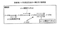
尚、上記実施例1のNW制御装置3の受信端ノード2を決定する方法について説明する。受信端ノード2は、増設チャネルの波長信号を増設する際の波長信号を受信する受信端のノード2とする。NW制御装置3は、チャネル毎のパス情報を格納するパス格納部36を有する。図29は、パス格納部36の一例を示す説明図である。図29に示すパス格納部36は、ch番号36Aと、送信端ノード36Bと、受信端ノード36Cと、中継ノード36Dとを対応付けて管理する。ch番号36Aは、波長信号のチャネルを識別する番号である。送信ノード36Bは、当該チャネルの波長信号を送信する送信端ノードである。受信ノード36Cは、当該チャネルの波長信号を受信する受信端ノードである。中継ノード36Dは、当該チャネルの波長信号を中継するノードである。
A method of determining the receiving
例えば、ch番号36Aが“ch1”の場合、送信ノード36Bを“ノード#7”、受信ノード36Cを“ノード#3”、中継ノード36Dを“ノード#2”とする。また、ch番号36Aが“ch2”の場合、送信ノード36Bを“ノード#6”、受信ノード36Cを“ノード#3”、中継ノード36Dを“ノード#1及びノード#2”とする。増設するチャネルのch番号36Aが“chx”の場合、送信ノード36Bを“ノード#1”、受信ノード36Cを“ノード#3”、中継ノード36Dを“ノード#2”とする。
For example, when the channel number 36A is “ch1”, the transmitting node 36B is “node # 7”, the receiving
図30は、受信端ノードの決定方法の一例を示す説明図である。NW制御装置3は、ch番号36Aの“chx”を増設する場合、パス格納部36を参照し、増設チャネル“chx”対応の受信ノード“ノード#3”を通過する各チャネルch1及びch2を受信端ノードとし、受信端ノードの受信BERmeaを取得することになる。
FIG. 30 is an explanatory diagram illustrating an example of a method of determining a receiving end node. When adding “chx” of the channel number 36A, the
また、図示した各部の各構成要素は、必ずしも物理的に図示の如く構成されていることを要しない。すなわち、各部の分散・統合の具体的形態は図示のものに限られず、その全部又は一部を、各種の負荷や使用状況等に応じて、任意の単位で機能的又は物理的に分散・統合して構成することができる。 In addition, each component of each unit illustrated does not necessarily need to be physically configured as illustrated. In other words, the specific form of distribution / integration of each unit is not limited to the one shown in the figure, and all or a part thereof is functionally or physically distributed / integrated in arbitrary units according to various loads and usage conditions. Can be configured.
更に、各装置で行われる各種処理機能は、CPU(Central Processing Unit)(又はMPU(Micro Processing Unit)、MCU(Micro Controller Unit)等のマイクロ・コンピュータ)上で、その全部又は任意の一部を実行するようにしても良い。また、各種処理機能は、CPU(又はMPU、MCU等のマイクロ・コンピュータ)で解析実行するプログラム上、又はワイヤードロジックによるハードウェア上で、その全部又は任意の一部を実行するようにしても良いことは言うまでもない。 In addition, various processing functions performed by each device can be implemented by a CPU (Central Processing Unit) (or a microcomputer such as an MPU (Micro Processing Unit) or an MCU (Micro Controller Unit)) in whole or in part. It may be executed. The various processing functions may be entirely or arbitrarily executed on a program that is analyzed and executed by a CPU (or a microcomputer such as an MPU or an MCU) or on hardware by wired logic. Needless to say.
2 ノード
3、3A NW制御装置
24 制御部
43 第1の演算部
44 第2の演算部
45 第3の演算部
46 第4の演算部
47 算出部
48 第5の演算部
49 第6の演算部
50 第1の算出部
51 第2の算出部
52 第3の算出部
2
Claims (7)
前記波長信号を受信する受信端のノードの受信BERを取得し、前記送信端のOSNR−BER特性から前記受信BER対応の第2のOSNRを算出する第2の演算部と、
前記第1のOSNRから前記許容限界BER対応の第1の雑音強度を算出する第3の演算部と、
前記第2のOSNRから前記受信BER対応の第2の雑音強度を算出する第4の演算部と、
前記第1の雑音強度及び前記第2の雑音強度に基づき、雑音強度マージンを算出する算出部と
を有することを特徴とするネットワーク制御装置。 A first calculation unit that calculates a first OSNR corresponding to an allowable limit BER from an OSNR-BER characteristic of a folded transmission end in a node at a transmission end that transmits a wavelength signal;
A second calculation unit that obtains a reception BER of a node at a reception end that receives the wavelength signal, and calculates a second OSNR corresponding to the reception BER from an OSNR-BER characteristic of the transmission end;
A third calculation unit that calculates a first noise intensity corresponding to the permissible limit BER from the first OSNR;
A fourth calculating unit that calculates a second noise intensity corresponding to the received BER from the second OSNR;
A calculation unit for calculating a noise intensity margin based on the first noise intensity and the second noise intensity.
前記第3の雑音強度、前記第2の雑音強度及び前記第1の雑音強度に基づき、前記許容限界BER対応の受信側の第4の雑音強度を算出する雑音強度算出部と、
前記第4の雑音強度から前記許容限界BER対応の受信側の第4のOSNRを算出する第6の演算部と、
前記第3のOSNR及び前記第4のOSNRに基づき、OSNRマージンを算出するマージン算出部と
を有することを特徴とする請求項1に記載のネットワーク制御装置。 A fifth calculation unit that obtains a third OSNR on the reception side corresponding to the reception BER from the node on the reception end, and calculates a third noise intensity on the reception side from the third OSNR;
A noise intensity calculator that calculates a fourth noise intensity on the receiving side corresponding to the permissible limit BER based on the third noise intensity, the second noise intensity, and the first noise intensity;
A sixth calculating unit that calculates a fourth OSNR of the receiving side corresponding to the permissible limit BER from the fourth noise intensity;
The network control device according to claim 1, further comprising: a margin calculation unit configured to calculate an OSNR margin based on the third OSNR and the fourth OSNR.
前記第3の雑音強度及び前記第2の雑音強度に基づき非線形雑音強度を算出する第1の算出部と、
前記第1の雑音強度及び前記非線形雑音強度に基づき、前記許容限界BER対応の受信側の第4の雑音強度を算出する第2の算出部と
を有することを特徴とする請求項2に記載のネットワーク制御装置。 The noise intensity calculator,
A first calculator for calculating a nonlinear noise intensity based on the third noise intensity and the second noise intensity;
3. A second calculator for calculating a fourth noise intensity on the receiving side corresponding to the permissible limit BER based on the first noise intensity and the non-linear noise intensity. 4. Network controller.
前記変更前の空き周波数帯域量及び前記変更後の空き周波数帯域量に応じて前記補正値を取得し、取得した前記補正値に基づき、前記OSNRマージンを補正する制御部と
を有することを特徴とする請求項2又は3に記載のネットワーク制御装置。 A correction table that stores a correction value in association with the vacant frequency band amount before the change of the wavelength signal and the vacant frequency band amount after the change,
A control unit that acquires the correction value according to the free frequency band amount before the change and the free frequency band amount after the change, and corrects the OSNR margin based on the obtained correction value. The network control device according to claim 2 or 3, wherein
前記変更前の入力パワー量及び前記変更後の入力パワー量に応じて前記補正値を取得し、取得した前記補正値に基づき、前記OSNRマージンを補正する制御部と
を有することを特徴とする請求項2又は3に記載のネットワーク制御装置。 A correction table for storing a correction value in association with the input power amount of the wavelength signal before the change and the input power amount of the wavelength signal after the change,
A control unit configured to obtain the correction value according to the input power amount before the change and the input power amount after the change, and to correct the OSNR margin based on the obtained correction value. Item 4. The network control device according to item 2 or 3.
前記送信端のノード内の送信器と受信器との間の波長信号の折り返し通信で順次測定したOSNR及びBERに対応する前記送信端のOSNR−BER特性を前記送信端のノードから取得することを特徴とする請求項1〜5の何れか一つに記載のネットワーク制御装置。 The first calculation unit is
Acquiring from the transmitting end node OSNR-BER characteristics of the transmitting end corresponding to the OSNR and BER sequentially measured in the return communication of the wavelength signal between the transmitter and the receiver in the transmitting end node. The network control device according to claim 1, wherein:
前記波長信号を受信する受信端のノードの受信BERを取得し、前記送信端のOSNR−BER特性から前記受信BER対応の第2のOSNRを算出し、
前記第1のOSNRから前記許容限界BER対応の第1の雑音強度を算出し、
前記第2のOSNRから前記受信BER対応の第2の雑音強度を算出し、
前記第1の雑音強度及び前記第2の雑音強度に基づき、雑音強度マージンを算出する
処理を実行することを特徴とする伝送品質マージン算出方法。 Calculating a first OSNR corresponding to the permissible limit BER from the OSNR-BER characteristic of the folded transmission end in the node at the transmission end transmitting the wavelength signal;
Acquiring the reception BER of the node at the reception end receiving the wavelength signal, calculating a second OSNR corresponding to the reception BER from the OSNR-BER characteristic of the transmission end,
Calculating a first noise intensity corresponding to the permissible limit BER from the first OSNR;
Calculating a second noise intensity corresponding to the received BER from the second OSNR;
A transmission quality margin calculation method, comprising: performing a process of calculating a noise intensity margin based on the first noise intensity and the second noise intensity.
Priority Applications (3)
| Application Number | Priority Date | Filing Date | Title |
|---|---|---|---|
| JP2016083995A JP6638535B2 (en) | 2016-04-19 | 2016-04-19 | Network control device and transmission quality margin calculation method |
| US15/470,409 US10177843B2 (en) | 2016-04-19 | 2017-03-27 | Network control apparatus and transmission quality margin calculation method |
| EP17163027.0A EP3236597A1 (en) | 2016-04-19 | 2017-03-27 | Network control apparatus and transmission quality margin calculation method |
Applications Claiming Priority (1)
| Application Number | Priority Date | Filing Date | Title |
|---|---|---|---|
| JP2016083995A JP6638535B2 (en) | 2016-04-19 | 2016-04-19 | Network control device and transmission quality margin calculation method |
Publications (2)
| Publication Number | Publication Date |
|---|---|
| JP2017195479A JP2017195479A (en) | 2017-10-26 |
| JP6638535B2 true JP6638535B2 (en) | 2020-01-29 |
Family
ID=58489483
Family Applications (1)
| Application Number | Title | Priority Date | Filing Date |
|---|---|---|---|
| JP2016083995A Active JP6638535B2 (en) | 2016-04-19 | 2016-04-19 | Network control device and transmission quality margin calculation method |
Country Status (3)
| Country | Link |
|---|---|
| US (1) | US10177843B2 (en) |
| EP (1) | EP3236597A1 (en) |
| JP (1) | JP6638535B2 (en) |
Families Citing this family (4)
| Publication number | Priority date | Publication date | Assignee | Title |
|---|---|---|---|---|
| US10587339B1 (en) * | 2018-11-27 | 2020-03-10 | Ciena Corporation | Systems and methods for achieving best effort home route capacity on protection paths during optical restoration |
| EP3758258B1 (en) * | 2019-06-27 | 2023-04-12 | Viavi Solutions Inc. | Measuring linear and non-linear transmission perturbations in optical transmission systems |
| CN111049579B (en) * | 2019-12-13 | 2021-05-04 | 苏州大学 | Protection method and system for preventing transmission quality prediction failure based on artificial intelligence |
| CN111010234B (en) * | 2019-12-23 | 2021-04-27 | 烽火通信科技股份有限公司 | Relay node selection method and system |
Family Cites Families (5)
| Publication number | Priority date | Publication date | Assignee | Title |
|---|---|---|---|---|
| JP3574578B2 (en) | 1998-12-18 | 2004-10-06 | 富士通株式会社 | Apparatus and method for equalizing transmission characteristics in wavelength division multiplexed optical communication system |
| EP2706708B1 (en) * | 2011-05-24 | 2015-09-16 | Huawei Technologies Co., Ltd. | Method and apparatus for path selection |
| JP6093273B2 (en) | 2013-08-30 | 2017-03-08 | 日本電信電話株式会社 | Penalty calculation method, penalty calculator, and digital coherent optical transmission system |
| GB2539123B (en) * | 2014-03-03 | 2020-10-28 | Eci Telecom Ltd | OSNR margin monitoring for optical coherent signals |
| RU2696560C2 (en) * | 2015-03-09 | 2019-08-05 | ИСиАй ТЕЛЕКОМ ЛТД. | Method of controlling operation of channels and optical communication system |
-
2016
- 2016-04-19 JP JP2016083995A patent/JP6638535B2/en active Active
-
2017
- 2017-03-27 US US15/470,409 patent/US10177843B2/en active Active
- 2017-03-27 EP EP17163027.0A patent/EP3236597A1/en not_active Withdrawn
Also Published As
| Publication number | Publication date |
|---|---|
| JP2017195479A (en) | 2017-10-26 |
| US10177843B2 (en) | 2019-01-08 |
| US20170302372A1 (en) | 2017-10-19 |
| EP3236597A1 (en) | 2017-10-25 |
Similar Documents
| Publication | Publication Date | Title |
|---|---|---|
| US10256903B2 (en) | Network controller and signal quality estimating method | |
| CN108781126B (en) | Optical transmission system, control device for wavelength selective switch, and insertion loss correction method | |
| JP6638535B2 (en) | Network control device and transmission quality margin calculation method | |
| US9413455B2 (en) | Apparatus and method for creating calibration coefficient used to monitor optical signal-to-noise ratio | |
| JP2011024189A (en) | Osnr monitor device, and osnr measurement device | |
| JP5564692B2 (en) | Optical transmission system and optical node | |
| US7912370B2 (en) | Optical power measurement apparatus and optical power measurement method | |
| US8620160B2 (en) | Optical transmission apparatus | |
| US9037002B2 (en) | Pre-emphasis control method and optical transmission system | |
| US10171163B2 (en) | Signal quality measurement device and signal quality measurement method | |
| JP2019220773A (en) | Optical transmission system, control arrangement, optical transmission method and transmission apparatus | |
| US9638574B2 (en) | Measurement apparatus and method of measuring signal light quality | |
| JP2011009864A (en) | Transmission system and method of correcting tilt of the transmission system | |
| JP6497439B2 (en) | COMMUNICATION DEVICE, COMMUNICATION METHOD, AND COMMUNICATION SYSTEM | |
| US9503187B2 (en) | Apparatus and method for retrieving data from a WDM signal, transmitter and method for transmitting a WDM signal, and WDM system | |
| JP2018133720A (en) | Optical transmission device and wavelength deviation detection method | |
| JP2014212402A (en) | Optical transmission device and optical transmission method | |
| JP6422799B2 (en) | Optical transmission system, optical transmitter and control method thereof | |
| US8798464B2 (en) | Setting optical power for an optical communications network channel | |
| JP2019180091A (en) | Receiver unit and reception method | |
| JP2016195358A (en) | Communication device and wavelength adjusting method |
Legal Events
| Date | Code | Title | Description |
|---|---|---|---|
| A621 | Written request for application examination |
Free format text: JAPANESE INTERMEDIATE CODE: A621 Effective date: 20190115 |
|
| A977 | Report on retrieval |
Free format text: JAPANESE INTERMEDIATE CODE: A971007 Effective date: 20191008 |
|
| TRDD | Decision of grant or rejection written | ||
| A01 | Written decision to grant a patent or to grant a registration (utility model) |
Free format text: JAPANESE INTERMEDIATE CODE: A01 Effective date: 20191126 |
|
| A61 | First payment of annual fees (during grant procedure) |
Free format text: JAPANESE INTERMEDIATE CODE: A61 Effective date: 20191209 |
|
| R150 | Certificate of patent or registration of utility model |
Ref document number: 6638535 Country of ref document: JP Free format text: JAPANESE INTERMEDIATE CODE: R150 |