JP6638163B2 - Combustor, gas turbine - Google Patents
Combustor, gas turbine Download PDFInfo
- Publication number
- JP6638163B2 JP6638163B2 JP2016065010A JP2016065010A JP6638163B2 JP 6638163 B2 JP6638163 B2 JP 6638163B2 JP 2016065010 A JP2016065010 A JP 2016065010A JP 2016065010 A JP2016065010 A JP 2016065010A JP 6638163 B2 JP6638163 B2 JP 6638163B2
- Authority
- JP
- Japan
- Prior art keywords
- combustor
- flange portion
- slit
- flame
- nozzle
- Prior art date
- Legal status (The legal status is an assumption and is not a legal conclusion. Google has not performed a legal analysis and makes no representation as to the accuracy of the status listed.)
- Active
Links
Images


Classifications
-
- F—MECHANICAL ENGINEERING; LIGHTING; HEATING; WEAPONS; BLASTING
- F23—COMBUSTION APPARATUS; COMBUSTION PROCESSES
- F23R—GENERATING COMBUSTION PRODUCTS OF HIGH PRESSURE OR HIGH VELOCITY, e.g. GAS-TURBINE COMBUSTION CHAMBERS
- F23R3/00—Continuous combustion chambers using liquid or gaseous fuel
- F23R3/02—Continuous combustion chambers using liquid or gaseous fuel characterised by the air-flow or gas-flow configuration
- F23R3/16—Continuous combustion chambers using liquid or gaseous fuel characterised by the air-flow or gas-flow configuration with devices inside the flame tube or the combustion chamber to influence the air or gas flow
- F23R3/18—Flame stabilising means, e.g. flame holders for after-burners of jet-propulsion plants
-
- F—MECHANICAL ENGINEERING; LIGHTING; HEATING; WEAPONS; BLASTING
- F02—COMBUSTION ENGINES; HOT-GAS OR COMBUSTION-PRODUCT ENGINE PLANTS
- F02C—GAS-TURBINE PLANTS; AIR INTAKES FOR JET-PROPULSION PLANTS; CONTROLLING FUEL SUPPLY IN AIR-BREATHING JET-PROPULSION PLANTS
- F02C3/00—Gas-turbine plants characterised by the use of combustion products as the working fluid
- F02C3/04—Gas-turbine plants characterised by the use of combustion products as the working fluid having a turbine driving a compressor
-
- F—MECHANICAL ENGINEERING; LIGHTING; HEATING; WEAPONS; BLASTING
- F23—COMBUSTION APPARATUS; COMBUSTION PROCESSES
- F23R—GENERATING COMBUSTION PRODUCTS OF HIGH PRESSURE OR HIGH VELOCITY, e.g. GAS-TURBINE COMBUSTION CHAMBERS
- F23R3/00—Continuous combustion chambers using liquid or gaseous fuel
- F23R3/02—Continuous combustion chambers using liquid or gaseous fuel characterised by the air-flow or gas-flow configuration
- F23R3/04—Air inlet arrangements
- F23R3/10—Air inlet arrangements for primary air
-
- F—MECHANICAL ENGINEERING; LIGHTING; HEATING; WEAPONS; BLASTING
- F23—COMBUSTION APPARATUS; COMBUSTION PROCESSES
- F23R—GENERATING COMBUSTION PRODUCTS OF HIGH PRESSURE OR HIGH VELOCITY, e.g. GAS-TURBINE COMBUSTION CHAMBERS
- F23R3/00—Continuous combustion chambers using liquid or gaseous fuel
- F23R3/28—Continuous combustion chambers using liquid or gaseous fuel characterised by the fuel supply
- F23R3/286—Continuous combustion chambers using liquid or gaseous fuel characterised by the fuel supply having fuel-air premixing devices
-
- F—MECHANICAL ENGINEERING; LIGHTING; HEATING; WEAPONS; BLASTING
- F23—COMBUSTION APPARATUS; COMBUSTION PROCESSES
- F23R—GENERATING COMBUSTION PRODUCTS OF HIGH PRESSURE OR HIGH VELOCITY, e.g. GAS-TURBINE COMBUSTION CHAMBERS
- F23R3/00—Continuous combustion chambers using liquid or gaseous fuel
- F23R3/28—Continuous combustion chambers using liquid or gaseous fuel characterised by the fuel supply
- F23R3/30—Continuous combustion chambers using liquid or gaseous fuel characterised by the fuel supply comprising fuel prevapourising devices
-
- F—MECHANICAL ENGINEERING; LIGHTING; HEATING; WEAPONS; BLASTING
- F23—COMBUSTION APPARATUS; COMBUSTION PROCESSES
- F23R—GENERATING COMBUSTION PRODUCTS OF HIGH PRESSURE OR HIGH VELOCITY, e.g. GAS-TURBINE COMBUSTION CHAMBERS
- F23R3/00—Continuous combustion chambers using liquid or gaseous fuel
- F23R3/28—Continuous combustion chambers using liquid or gaseous fuel characterised by the fuel supply
- F23R3/34—Feeding into different combustion zones
- F23R3/346—Feeding into different combustion zones for staged combustion
-
- F—MECHANICAL ENGINEERING; LIGHTING; HEATING; WEAPONS; BLASTING
- F23—COMBUSTION APPARATUS; COMBUSTION PROCESSES
- F23R—GENERATING COMBUSTION PRODUCTS OF HIGH PRESSURE OR HIGH VELOCITY, e.g. GAS-TURBINE COMBUSTION CHAMBERS
- F23R3/00—Continuous combustion chambers using liquid or gaseous fuel
- F23R3/42—Continuous combustion chambers using liquid or gaseous fuel characterised by the arrangement or form of the flame tubes or combustion chambers
- F23R3/46—Combustion chambers comprising an annular arrangement of several essentially tubular flame tubes within a common annular casing or within individual casings
-
- F—MECHANICAL ENGINEERING; LIGHTING; HEATING; WEAPONS; BLASTING
- F05—INDEXING SCHEMES RELATING TO ENGINES OR PUMPS IN VARIOUS SUBCLASSES OF CLASSES F01-F04
- F05D—INDEXING SCHEME FOR ASPECTS RELATING TO NON-POSITIVE-DISPLACEMENT MACHINES OR ENGINES, GAS-TURBINES OR JET-PROPULSION PLANTS
- F05D2240/00—Components
- F05D2240/35—Combustors or associated equipment
-
- F—MECHANICAL ENGINEERING; LIGHTING; HEATING; WEAPONS; BLASTING
- F23—COMBUSTION APPARATUS; COMBUSTION PROCESSES
- F23R—GENERATING COMBUSTION PRODUCTS OF HIGH PRESSURE OR HIGH VELOCITY, e.g. GAS-TURBINE COMBUSTION CHAMBERS
- F23R2900/00—Special features of, or arrangements for continuous combustion chambers; Combustion processes therefor
- F23R2900/00005—Preventing fatigue failures or reducing mechanical stress in gas turbine components
Description
本発明は、燃焼器、ガスタービンに関する。 The present invention relates to a combustor and a gas turbine.
ガスタービンに用いられる燃焼器は、拡散火炎、又は予混合火炎を形成するための第一の燃料ノズルと、この火炎による着火を経て予混合火炎を形成する第二の燃料ノズルと、を備えている。第一の燃料ノズルの下流側端部は、第二の燃料ノズルによって形成された予混合火炎を安定化させるための保炎器によって覆われていることが一般的である(下記特許文献1参照)。特許文献1に記載された保炎器は、上流側から下流側に向かうに従って拡径するコーン状をなしている。 A combustor used for a gas turbine includes a first fuel nozzle for forming a diffusion flame or a premixed flame, and a second fuel nozzle for forming a premixed flame through ignition by the flame. I have. The downstream end of the first fuel nozzle is generally covered by a flame stabilizer for stabilizing the premixed flame formed by the second fuel nozzle (see Patent Document 1 below). ). The flame stabilizer described in Patent Literature 1 has a cone shape whose diameter increases from the upstream side to the downstream side.
しかしながら、上記のような保炎器を設けることで予混合火炎に対する保炎を実現できる一方で、保炎器自体が火炎に曝されることで、当該保炎器に熱変形を生じることがある。保炎器が変形した場合、その下流側に形成される予混合火炎の形状や燃焼ガスの性状に影響が及んでしまい、燃焼器の安定的な運転に支障を来すことがある。 However, by providing the flame stabilizing device as described above, while flame holding against the premixed flame can be realized, when the flame stabilizing device itself is exposed to the flame, the flame stabilizing device may be thermally deformed. . When the flame stabilizer is deformed, it affects the shape of the premixed flame formed downstream of the flame stabilizer and the properties of the combustion gas, which may hinder stable operation of the combustor.
本発明は上記課題を解決するためになされたものであって、保炎器に熱変形を生じた場合であっても安定的に運転することが可能な燃焼器、及びこれを備えるガスタービンを提供することを目的とする。 The present invention has been made in order to solve the above-described problems, and provides a combustor that can be stably operated even when thermal deformation occurs in a flame stabilizer, and a gas turbine including the same. The purpose is to provide.
本発明の第一の態様によれば、燃焼器は、軸線に沿って延び、下流側に向かって燃料を噴射する第一ノズルと、前記第一ノズルの下流側端部を外周側から覆う保炎器と、前記保炎器の外周側で、軸線の周方向に間隔をあけて配列された複数の第二ノズルと、を備え、前記保炎器は、上流側から下流側に向かうにしたがって拡径するコーン部と、該コーン部の下流側の端縁から径方向外側に向かって広がるフランジ部と、を有し、少なくとも前記フランジ部には、該フランジ部を軸線方向に貫通する貫通部が形成されており、前記貫通部を下流側から覆う調整板を有し、該調整板には前記貫通部よりも小さな開孔面積を有するとともに、該貫通部に連通された調整貫通部が形成されている。 According to the first aspect of the present invention, a combustor includes a first nozzle extending along an axis and injecting fuel toward a downstream side, and a protective cover for covering a downstream end of the first nozzle from an outer peripheral side. Flame device, comprising a plurality of second nozzles arranged on the outer peripheral side of the flame stabilizer at intervals in the circumferential direction of the axis, wherein the flame stabilizer is downstream from the upstream side to the downstream side A cone portion having a diameter that increases and a flange portion that extends radially outward from an edge on the downstream side of the cone portion, and at least the flange portion has a through portion that penetrates the flange portion in the axial direction. And an adjusting plate that covers the through portion from the downstream side. The adjusting plate has an opening area smaller than that of the through portion, and has an adjusting through portion that communicates with the through portion. Have been.
この構成によれば、少なくともフランジ部に貫通部が形成されているため、保炎器が火炎の熱に曝された場合であっても、貫通部が当該貫通部の周辺部分における熱応力を吸収することによって熱変形を抑制することができる。すなわち、フランジ部以外の部分に上記熱変形の影響が及ぶ可能性を低減することができる。
また、調整貫通部が形成された調整板によって貫通部が下流側から覆われている。これにより、貫通部によって熱応力を逃がすことができることに加えて、調整板の調整貫通部によって貫通部を通過する空気の量を調整することができる。
According to this configuration, since the through portion is formed at least in the flange portion, even when the flame stabilizer is exposed to the heat of the flame, the through portion absorbs the thermal stress in the peripheral portion of the through portion. By doing so, thermal deformation can be suppressed. That is, it is possible to reduce the possibility that the thermal deformation affects portions other than the flange portion.
In addition, the penetrating portion is covered from the downstream side by the adjusting plate in which the adjusting penetrating portion is formed. Thus, in addition to allowing the thermal stress to be released by the penetration portion, the amount of air passing through the penetration portion can be adjusted by the adjustment penetration portion of the adjusting plate.
本発明の第二の態様によれば、上記の燃焼器では、前記貫通部は、前記フランジ部の径方向外側から内側に向かって延びるフランジ部スリット、及び該フランジ部スリットに連通するとともに前記コーン部の下流側の端部を含む領域に形成されたコーン部スリットであってもよい。 According to a second aspect of the present invention, in the above-described combustor, the penetrating portion communicates with the flange slit extending inward from a radially outer side of the flange, and the cone communicates with the flange slit. It may be a cone slit formed in a region including the downstream end of the portion.
この構成では、フランジ部にフランジ部スリットが形成されていることに加えて、当該フランジ部スリットに連通するコーン部スリットがコーン部に形成されている。これにより、保炎器が熱に曝された場合には、フランジ部スリットによって熱変形が吸収されるとともに、コーン部スリットによってもこの熱応力が吸収される。これにより、フランジ部とコーン部との接続部(コーン部の径方向外側の端縁)に生じる熱変形を低減することができる。すなわち、保炎器の耐久性を向上させることができる。 In this configuration, in addition to the flange slit being formed in the flange, a cone slit communicating with the flange slit is formed in the cone. Thus, when the flame stabilizer is exposed to heat, the thermal deformation is absorbed by the flange slits, and the thermal stress is also absorbed by the cone slits. Thereby, the thermal deformation generated at the connection portion between the flange portion and the cone portion (the radially outer edge of the cone portion) can be reduced. That is, the durability of the flame stabilizer can be improved.
本発明の第三の態様によれば、上記の燃焼器では、前記貫通部は、前記フランジ部を軸線方向に貫通する孔部であってもよい。 According to a third aspect of the present invention, in the above-described combustor, the through portion may be a hole that passes through the flange portion in the axial direction.
この構成によれば、フランジ部に貫通部としての孔部が形成されているため、保炎器が火炎の熱に曝された場合であっても、当該孔部によって熱応力を吸収することができる。すなわち、コーン部に上記熱応力の影響が及ぶ可能性を低減することができる。 According to this configuration, since the hole as the penetration portion is formed in the flange portion, even when the flame stabilizer is exposed to the heat of the flame, the hole can absorb the thermal stress. it can. That is, it is possible to reduce the possibility that the thermal stress affects the cone portion.
本発明の第四の態様によれば、上記の燃焼器では、前記貫通部が、少なくとも前記フランジ部上で軸線の周方向に間隔をあけて複数形成されていてもよい。 According to a fourth aspect of the present invention, in the above-described combustor, a plurality of the penetrating portions may be formed at least on the flange portion at intervals in a circumferential direction of an axis.
この構成では、複数の貫通部が軸線の周方向に間隔をあけて設けられている。これにより、保炎器が熱に曝された場合であっても、熱応力を周方向に均一に吸収することができる。言い換えれば、保炎器が周方向にわたって不均一に変形する可能性を低減することができる。 In this configuration, a plurality of penetration portions are provided at intervals in the circumferential direction of the axis. Thereby, even when the flame stabilizer is exposed to heat, the thermal stress can be uniformly absorbed in the circumferential direction. In other words, the possibility that the flame stabilizer deforms unevenly in the circumferential direction can be reduced.
本発明の第五の態様によれば、上記の燃焼器では、各前記第二ノズルの下流側に設けられ、軸線方向に延びる筒状をなすとともに、軸線の周方向に間隔をあけて配列された延長管を複数備え、前記フランジ部上における前記貫通部が設けられる周方向位置は、互いに隣接する一対の延長管同士の間であってもよい。 According to the fifth aspect of the present invention, in the above-described combustor, the combustor is provided on the downstream side of each of the second nozzles, has a cylindrical shape extending in the axial direction, and is arranged at intervals in the circumferential direction of the axial line. A plurality of extension pipes may be provided, and a circumferential position on the flange portion where the penetration portion is provided may be between a pair of extension pipes adjacent to each other.
各延長管内では、第二ノズルの下流側に形成された火炎が下流側に向かって延びている。一方で、保炎器の上流側からは燃焼器の外部から導かれた空気が下流側に向かって流通している。仮に、保炎器に形成された貫通部の周方向位置が、各延長管の周方向位置と重複している場合、火炎に供給される混合気の組成が変化し、燃焼性に影響を与える可能性がある。しかしながら、上記の構成では、貫通部の周方向位置が延長管同士の間とされている。言い換えれば、貫通部は、周方向において各延長管とは異なる位置に形成されている。また、これら延長管同士の間の空間には上流側から空気が流れている。これにより、貫通部を通過した空気が火炎に衝突する可能性を低減することができる。 In each extension pipe, a flame formed on the downstream side of the second nozzle extends toward the downstream side. On the other hand, air guided from outside the combustor flows from the upstream side of the flame stabilizer to the downstream side. If the circumferential position of the penetrating portion formed in the flame stabilizer overlaps with the circumferential position of each extension pipe, the composition of the air-fuel mixture supplied to the flame changes, affecting the combustibility. there is a possibility. However, in the above configuration, the circumferential position of the penetrating portion is between the extension tubes. In other words, the penetrating portion is formed at a position different from each extension tube in the circumferential direction. In addition, air flows from the upstream side into the space between these extension tubes. Thereby, the possibility that the air passing through the penetrating portion collides with the flame can be reduced.
本発明の第七の態様によれば、ガスタービンは、高圧空気を生成する圧縮機と、高圧空気と燃料とを混合し、燃焼させることで燃焼ガスを生成する請求項1から5のいずれか一項に記載の燃焼器と、燃焼ガスによって駆動されるタービンと、を備える。 According to a seventh aspect of the present invention, the gas turbine generates a combustion gas by mixing a high-pressure air and a fuel with a compressor that generates a high-pressure air and burning the mixture. A combustor according to claim 1, and a turbine driven by combustion gas.
この構成によれば、安定的に運転することが可能なガスタービンを提供することができる。 According to this configuration, a gas turbine that can operate stably can be provided.
本発明によれば、保炎器に熱変形を生じた場合であっても安定的に運転することが可能な燃焼器、及びこれを備えるガスタービンを提供することができる。 Advantageous Effects of Invention According to the present invention, it is possible to provide a combustor that can stably operate even when thermal deformation occurs in a flame stabilizer, and a gas turbine including the combustor.
本発明の実施形態について図1から図5を参照して説明する。図1に示すように、本実施形態に係るガスタービン100は、高圧空気を生成する圧縮機1と、高圧空気に燃料を混合して燃焼させることで燃焼ガスを生成する燃焼器3と、燃焼ガスによって駆動されるタービン2と、を備えている。
An embodiment of the present invention will be described with reference to FIGS. As shown in FIG. 1, a
圧縮機1は、主軸線Am回りに回転する圧縮機ロータ11と、圧縮機ロータ11を外周側から覆う圧縮機ケーシング12と、を有している。圧縮機ロータ11は、主軸線Amに沿って延びる柱状をなしている。圧縮機ロータ11の外周面上には、主軸線Am方向に間隔をあけて配列された複数の圧縮機動翼段13が設けられている。各圧縮機動翼段13は、圧縮機ロータ11の外周面上で主軸線Amの周方向に間隔をあけて配列された複数の圧縮機動翼14を有している。
The compressor 1 has a
圧縮機ケーシング12は、主軸線Amを中心とする筒状をなしている。圧縮機ケーシング12の内周面には、主軸線Am方向に間隔をあけて配列された複数の圧縮機静翼段15が設けられている。これらの圧縮機静翼段15は、上記の圧縮機動翼段13に対して、主軸線Am方向から見て交互に配列されている。各圧縮機静翼段15は、圧縮機ケーシング12の内周面上で、主軸線Amの周方向に間隔をあけて配列された複数の圧縮機静翼16を有している。
The
燃焼器3は、上記の圧縮機ケーシング12と、後述するタービンケーシング22との間に設けられている。圧縮機1で生成された高圧空気は、燃焼器3内部で燃料と混合されて予混合ガスとなる。燃焼器3内で、この予混合ガスが燃焼することで高温高圧の燃焼ガスが生成される。燃焼ガスは、タービンケーシング22内に導かれてタービン2を駆動する。
The
タービン2は、主軸線Am回りに回転するタービンロータ21と、タービンロータ21を外周側から覆うタービンケーシング22と、を有している。タービンロータ21は、主軸線Amに沿って延びる柱状をなしている。タービンロータ21の外周面上には、主軸線Am方向に間隔をあけて配列された複数のタービン動翼段23が設けられている。各タービン動翼段23は、タービンロータ21の外周面上で、主軸線Amの周方向に間隔をあけて配列された複数のタービン動翼24を有している。このタービンロータ21は、上記の圧縮機ロータ11に対して主軸線Am方向に一体に連結されることで、ガスタービンロータ91を形成する。
The
タービンケーシング22は、主軸線Amを中心とする筒状をなしている。タービンケーシング22の内周面には、主軸線Am方向に間隔をあけて配列された複数のタービン静翼段25が設けられている。これらのタービン静翼段25は、上記のタービン動翼段23に対して、主軸線Am方向から見て交互に配列されている。各タービン静翼段25は、タービンケーシング22の内周面上で、主軸線Amの周方向に間隔をあけて配列された複数のタービン静翼26を有している。タービンケーシング22は、上記の圧縮機ケーシング12に対して主軸線Am方向に連結されることで、ガスタービンケーシング92を形成する。すなわち、上記のガスタービンロータ91は、このガスタービンケーシング92内で、主軸線Am回りに一体に回転可能とされている。
The
続いて、本実施形態に係る燃焼器3の詳細な構成について、図2と図3を参照して説明する。図2に示すように、燃焼器3は、燃焼器軸線Ac(軸線)を中心とする筒状の燃焼器本体3Mと、燃焼器本体3Mに燃料を供給する燃料ノズル3Nと、を有している。燃焼器本体3Mは、燃料ノズル3Nを収容する第一筒体41と、燃焼器軸線Acに沿って第一筒体41に接続される第二筒体42と、を有している。なお、以降の説明では、燃焼器軸線Acの延びる方向において、第二筒体42から見て第一筒体41が位置する側を上流側と呼び、第一筒体41から見て第二筒体42が位置する側を下流側と呼ぶ。すなわち、燃焼器3中で生成された燃焼ガスは上流側から下流側に向かって流通する。
Subsequently, a detailed configuration of the
第一筒体41の外径寸法は、第二筒体42の内径寸法よりも小さく設定されている。これにより、第一筒体41の下流側の端部は、第二筒体42の上流側の端部内に挿通された状態となっている。第一筒体41は、燃焼器軸線Acを中心とする円筒状をなしている。第二筒体42は、上流側から下流側に向かうにしたがって次第に縮径している。燃料ノズル3Nは、主として第二筒体42内に向けて上流側から燃料を供給する。
The outer diameter of the
図3に拡大して示すように、第一筒体41の内周側であって、下流側の端部に近接する領域には、燃焼器軸線Acを中心とする円盤状の基板43が設けられている。基板43の径寸法は、第一筒体41の内径寸法と同一か、わずかに小さく設定されている。基板43には、燃料ノズル3Nを第一筒体41内で支持するためのノズル支持開孔44(第一支持開孔44A、第二支持開孔44B)が形成されている。
As shown in an enlarged manner in FIG. 3, a disk-shaped
燃料ノズル3Nは、第一ノズル51と、第二ノズル52とを有している。第一ノズル51は、燃焼器軸線Acに沿って第一筒体41内に1つ設けられている。第一ノズル51は、燃焼器軸線Acを中心とする管状をなしており、その内部には燃料を導くための流路(図示省略)が形成されている。さらに、第一ノズル51の下流側端部には、上記流路を通じて導かれた燃料を第一筒体41内に向かって噴射するための噴射孔(図示省略)が形成されている。
The fuel nozzle 3N has a
第二ノズル52は、燃焼器軸線Acの周方向に間隔をあけて複数設けられている。各第二ノズル52は、燃焼器軸線Acに平行に延びる第二ノズル本体52Mと、第二ノズル本体52Mの外面に設けられた旋回翼60と、これら第二ノズル本体52M、及び旋回翼60を外周側から覆うノズル筒70と、を有している。
A plurality of
第二ノズル本体52Mは、上流側から下流側に向かうにしたがって次第に先細りとなるように形成されている。すなわち、第二ノズル本体52Mの先端部は尖頭状をなしている。第二ノズル本体52Mの内部には、燃料が流通する流路(図示省略)が形成されている。この流路は、旋回翼60の翼面上に形成された複数の噴射孔を通じて外部に連通している。
The
さらに、上記の各ノズル筒70の下流側には、該ノズル筒70と同軸に延びる筒状の延長管80がそれぞれ設けられている。これらの延長管80は、燃焼器軸線Acの周方向に間隔をあけて複数(8つ)配置されている。詳しくは図示しないが、各延長管80の断面形状は、上流側から下流側に向かうに従って、円形から矩形になるように次第に変形している。すなわち、延長管80の上流側の端部は円形の断面を有している一方で、下流側の端部は矩形の断面を有している。さらに、各延長管80の径方向内側の面は、上流側から下流側に向かうに従って、径方向内側から外側に向かって湾曲している。これにより、延長管80と後述する保炎器52Cとが干渉しないようになっている。
Further, on the downstream side of each of the
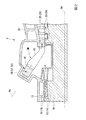
第一ノズル51の下流側端部には、当該端部を外周側から覆う保炎器52Cが設けられている。保炎器52Cは、第一ノズル51から噴射された燃料によって形成される火炎(拡散火炎)を保炎する目的で設けられる。より詳細には、本実施形態に係る保炎器52Cは、第一ノズル51の下流側の端部を外周側から覆う筒状部C1と、筒状部C1の下流側に設けられたコーン部C2、及びフランジ部C3と、を有している。
At the downstream end of the
筒状部C1は、燃焼器軸線Acを中心とする円筒状をなしている。コーン部C2及びフランジ部C3は、この筒状部C1の下流側の端部に一体に接続されている。コーン部C2は、上流側から下流側に向かうに従って次第に拡径することで円錐状をなしている。フランジ部C3は、このコーン部C2の下流側の端縁(すなわち、最外周部)から、燃焼器軸線Acの径方向外側に向かって広がっている。燃焼器軸線Ac方向におけるフランジ部C3の位置は、延長管80の下流側の端部の位置と同一とされている。さらに、筒状部C1は上述の基板43に形成された第一支持開孔44A内に挿通されることで外周側から支持されている。
The cylindrical portion C1 has a cylindrical shape centered on the combustor axis Ac. The cone part C2 and the flange part C3 are integrally connected to the downstream end of the cylindrical part C1. The cone portion C2 has a conical shape by gradually increasing the diameter from the upstream side to the downstream side. The flange portion C3 extends radially outward from the combustor axis Ac from the downstream edge (ie, the outermost peripheral portion) of the cone portion C2. The position of the flange portion C3 in the direction of the combustor axis Ac is the same as the position of the downstream end of the
さらに、図5に示すように、本実施形態に係る保炎器52Cには、複数のスリットS(貫通部)が形成されている。より具体的には、これらのスリットSは、上述のフランジ部C3及びコーン部C2の一部にかけて、燃焼器軸線Acの周方向に等間隔をあけて形成されている。各スリットSは、フランジ部C3の径方向内側から外側に向かって延びるフランジ部スリットSfと、このフランジ部スリットSfに連通されるとともに、コーン部C2の下流側の端部を含む部分に形成されたコーン部スリットScと、によって構成されている。フランジ部スリットSf、及びコーン部スリットScは、フランジ部C3,コーン部C2にそれぞれ径方向に延びる切欠きを形成することで得られる。これらのスリットSによってフランジ部C3は周方向に等分割されている。また、スリットSの周方向における端面同士の間には、周方向に広がる間隙が形成されている。
Further, as shown in FIG. 5, a plurality of slits S (penetrating portions) are formed in the
図4に示すように、保炎器52Cに形成されたスリットSの周方向位置は、互いに隣接する一対の延長管80同士の間とされている。言い換えると、スリットSの周方向位置は、延長管80自体の周方向位置と異なっており、これらスリットSと延長管80とは周方向において重ならないように配置されている。さらに、スリットSの周方向における寸法は、延長管80同士の間の周方向寸法よりも十分に小さく設定されている。
As shown in FIG. 4, the circumferential position of the slit S formed in the
続いて、本実施形態に係るガスタービン100、及び燃焼器3の動作について説明する。ガスタービン100を運転するに当たっては、まず外部の駆動源によって圧縮機ロータ11(ガスタービンロータ91)を回転駆動する。圧縮機ロータ11の回転に伴って外部の空気が順次圧縮され、高圧空気が生成される。この高圧空気は、圧縮機ケーシング12内部の空間を通じて燃焼器3内に供給される。燃焼器3内では、燃料ノズル3Nから供給された燃料がこの高圧空気に混合されて燃焼し、高温高圧の燃焼ガスが生成される。燃焼ガスはタービンケーシング22内部の空間を通じてタービン2内に供給される。タービン2内では、タービン動翼段23、及びタービン静翼段25に燃焼ガスが順次衝突することで、タービンロータ21(ガスタービンロータ91)に対して回転駆動力が与えられる。この回転エネルギーは、軸端に連結された発電機等の駆動に利用される。
Subsequently, operations of the
次に、燃焼器3の詳細な動作について、図3を再び参照して説明する。同図に示すように、圧縮機1で生成された高圧空気は、燃焼器軸線Acの一方側(上流側)から第一筒体41内に供給される。第一筒体41内に導入された高圧空気は、上記のノズル筒70の内周側の空間を経て、下流側の第二筒体42内に到達する。ここで、ノズル筒70内では、上記の旋回翼60に形成された噴射孔から噴射された燃料が、高圧空気に混合される。これにより、ノズル筒70内では、燃料と高圧空気とを含む予混合ガスが生成される。このとき、予混合ガスの流れには、旋回翼60によって与えられた旋回流成分が含まれている。
Next, a detailed operation of the
一方で、第一ノズル51から噴射された燃料は、着火器(図示省略)によって着火されることで、該第一ノズル51から下流側に向かって延びる拡散火炎(又は予混合火炎)を形成する。この火炎が上記ノズル筒70内に存在する予混合ガスに伝播することで、複数の第二ノズル52の下流側には予混合火炎が形成される。この予混合火炎は、上記の旋回流成分を伴って、第二筒体42内で上流側から下流側に向かって延びるとともに、高温高圧の燃焼ガスを生成する。燃焼ガスは、第二筒体42内を上流側から下流側に向かって流れた後、上記のタービンケーシング22内に導入されてタービン2を駆動する。
On the other hand, the fuel injected from the
上記の第二ノズル52によって形成される予混合火炎は、該第二ノズル52に近接して配置された保炎器52Cによって保炎される。具体的には、予混合火炎の形状や、燃焼ガスの流速分布は、この保炎器52Cによって周方向全域にかけて均一に維持されることが望ましい。ここで、保炎器52Cには火炎による熱が伝播する。この熱によって、保炎器52Cに熱応力が加わることがある。この熱応力によって、保炎器52Cに過度の熱変形が生じた場合、上記のような火炎の形状や燃焼ガスの流速分布に乱れが生じる虞がある。このような乱れは、燃焼器3の安定的な運転に影響を及ぼしてしまう。
The premixed flame formed by the above-described
そこで、本実施形態では上述のように保炎器52Cに複数のスリットSが形成されている。特に、保炎器52Cのフランジ部C3にフランジ部スリットSfが形成されているため、保炎器52Cが火炎の熱に曝された場合であっても、当該フランジ部スリットSfの周辺部分における熱応力を逃がすことができる。。すなわち、フランジ部C3と一体に形成されたコーン部C2に熱変形が生じる可能性を低減することができる。さらに言い換えると、スリットSが形成されていない構成に比べて、熱変形が生じる領域をフランジ部C3の周辺のみに限定し、かつその面積を小さく抑えることができる。
Therefore, in the present embodiment, a plurality of slits S are formed in the
さらに、上記の構成では、フランジ部スリットSfに連通するコーン部スリットScがコーン部C2に形成されている。これにより、保炎器52Cが熱に曝された場合には、コーン部スリットScによっても熱応力が吸収される。その結果、フランジ部C3とコーン部C2との接続部(コーン部C2の径方向外側の端縁)における熱変形を抑制することができる。これにより、保炎器52Cの耐久性を向上させることができる。反対に、フランジ部スリットSfのみが形成されている場合、当該接続部に応力が集中してしまうため、疲労破壊等を生じる虞がある。
Furthermore, in the above-described configuration, the cone slit Sc communicating with the flange slit Sf is formed in the cone C2. Thereby, when the
加えて、上記の構成では、保炎器52Cには複数のスリットSが燃焼器軸線Acの周方向に間隔をあけて設けられている。これにより、保炎器52Cが熱に曝された場合であっても、当該保炎器52Cに加わる熱応力を周方向に均一化させることができる。これにより、保炎器52Cが周方向にわたって不均一に変形する可能性を低減することができる。したがって、保炎器52Cに生じた熱変形によって、火炎の形状に影響が及ぶ可能性を低減することができる。
In addition, in the above configuration, a plurality of slits S are provided in the
さらに上記の燃焼器3では、フランジ部C3上におけるスリットSの周方向位置は、延長管80同士の間とされている。ここで、各延長管80内では、第二ノズル52の下流側に形成された火炎が下流側に向かって延びている。一方で、保炎器52Cの上流側からは燃焼器3の外部から導かれた空気が下流側に向かって流通している。仮に、保炎器52Cに形成されたスリットSの周方向位置が、各延長管80の周方向位置と重なっている場合、各延長管80の下流側に形成される火炎に、スリットSを通過した空気が供給されるため、火炎に供給される混合気の組成が変化し、燃焼性に影響を与える可能性がある。
Further, in the
しかしながら、上記の構成では、フランジ部C3上におけるスリットSの周方向位置が、延長管80同士の間とされている。言い換えれば、スリットSは、周方向において各延長管80とは異なる位置に形成されている。また、これら延長管80同士の間の空間には上流側から空気が流れている。これにより、スリットSを通過した空気が燃焼性に影響を与える可能性を低減することができる。したがって、燃焼器3をさらに安定的に運転することが可能となる。
However, in the above configuration, the circumferential position of the slit S on the flange portion C3 is between the
以上、本発明の実施形態について説明した。なお、本発明の要旨を逸脱しない限りにおいて、上記の構成に種々の変更を加えることが可能である。例えば、上記実施形態では貫通部として、スリットSを保炎器52Cに形成した例について説明した。しかしながら、貫通部の態様はスリットSに限定されない。
The embodiment of the invention has been described. Note that various changes can be made to the above-described configuration without departing from the spirit of the present invention. For example, in the above-described embodiment, an example in which the slit S is formed in the
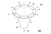
他の例(変形例)として、図6に示すように、フランジ部C3上に当該フランジ部C3を燃焼器軸線Ac方向に貫通する複数の孔部Hを形成する構成も考えられる。具体的には、これらの孔部Hは、燃焼器軸線Ac方向から見て矩形の開孔形状を有している。また、これらの孔部Hは、フランジ部C3上で周方向に等間隔をあけて配列されている。この構成によっても、上記実施形態と同様に、孔部Hの周辺における熱応力を逃がすことができるため、保炎器52C全体に歪みを生じる可能性を低減することができる。
As another example (modification), as shown in FIG. 6, a configuration in which a plurality of holes H penetrating through the flange portion C3 in the combustor axis line Ac direction on the flange portion C3 may be considered. Specifically, these holes H have a rectangular opening shape when viewed from the direction of the combustor axis Ac. Further, these holes H are arranged at equal intervals in the circumferential direction on the flange portion C3. With this configuration as well, as in the above-described embodiment, the thermal stress around the hole H can be released, so that the possibility of distortion of the
なお、上述したスリットSと孔部Hとを、同一の保炎器52C上に形成することも可能である。例えば、スリットSと孔部Hとを保炎器52Cの周方向に交互に配列することも可能である。
The above-mentioned slit S and hole H can be formed on the
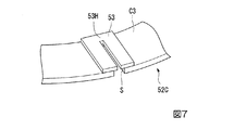
さらに他の例として、図7に示すように、保炎器52Cに、上述したスリットS(又は孔部H)を下流側から覆う板状の調整板53を設けることも可能である。この調整板53には、スリットSの開孔面積よりも小さな開孔面積を有する調整貫通部53Hが形成されている。より具体的には、調整貫通部53Hは、調整板53の外周側の端縁から径方向内側に向かって凹没する切欠き状をなしている。さらに、調整貫通部53HとスリットSとは、互いに連通されている。このような構成によれば、スリットSによって熱応力を逃がすことができることに加えて、調整板53の調整貫通部53HによってスリットSを通過する空気の量を調整することができる。これにより、スリットSを通過した空気が燃焼性に影響を与える可能性をさらに低減することができる。
As yet another example, as shown in FIG. 7, a plate-shaped
1…圧縮機
2…タービン
3…燃焼器
3M…燃焼器本体
3N…燃料ノズル
11…圧縮機ロータ
12…圧縮機ケーシング
13…圧縮機動翼段
14…圧縮機動翼
15…圧縮機静翼段
16…圧縮機静翼
21…タービンロータ
22…タービンケーシング
23…タービン動翼段
24…タービン動翼
25…タービン静翼段
26…タービン静翼
41…第一筒体
42…第二筒体
43…基板
44…ノズル支持開孔
44A…第一支持開孔
44B…第二支持開孔
51…第一ノズル
52…第二ノズル
52C…保炎器
52M…第二ノズル本体
60…旋回翼
70…ノズル筒
80…延長管
91…ガスタービンロータ
92…ガスタービンケーシング
100…ガスタービン
Ac…燃焼器軸線
Am…主軸線
C1…筒状部
C2…コーン部
C3…フランジ部
H…孔部
S…スリット
Sc…コーン部スリット
Sf…フランジ部スリット
DESCRIPTION OF SYMBOLS 1 ...
Claims (6)
前記第一ノズルの下流側端部を外周側から覆う保炎器と、
前記保炎器の外周側で、軸線の周方向に間隔をあけて配列された複数の第二ノズルと、
を備え、
前記保炎器は、上流側から下流側に向かうにしたがって拡径するコーン部と、該コーン部の下流側の端縁から径方向外側に向かって広がるフランジ部と、を有し、
少なくとも前記フランジ部には、該フランジ部を軸線方向に貫通する貫通部が形成されており、
前記貫通部を下流側から覆う調整板を有し、該調整板には前記貫通部よりも小さな開孔面積を有するとともに、該貫通部に連通された調整貫通部が形成されている燃焼器。 A first nozzle that extends along an axis and injects fuel downstream.
A flame stabilizer covering the downstream end of the first nozzle from the outer peripheral side,
On the outer peripheral side of the flame stabilizer, a plurality of second nozzles arranged at intervals in the circumferential direction of the axis,
With
The flame stabilizer has a cone portion that expands in diameter from the upstream side to the downstream side, and a flange portion that expands radially outward from a downstream edge of the cone portion,
At least the flange portion has a penetrating portion penetrating the flange portion in the axial direction ,
A combustor comprising: an adjusting plate that covers the through portion from a downstream side; the adjusting plate has an opening area smaller than that of the through portion, and has an adjusting through portion that is communicated with the through portion .
前記フランジ部上における前記貫通部が設けられる周方向位置は、互いに隣接する一対の延長管同士の間である請求項1に記載の燃焼器。 Provided on the downstream side of each of the second nozzles, having a cylindrical shape extending in the axial direction, provided with a plurality of extension tubes arranged at intervals in the circumferential direction of the axis,
The combustor according to claim 1, wherein a circumferential position on the flange portion where the through portion is provided is between a pair of extension tubes adjacent to each other.
高圧空気と燃料とを混合し、燃焼させることで燃焼ガスを生成する請求項1から5のいずれか一項に記載の燃焼器と、
燃焼ガスによって駆動されるタービンと、
を備えるガスタービン。 A compressor for producing high-pressure air;
The combustor according to any one of claims 1 to 5 , wherein the high-pressure air and the fuel are mixed and burned to generate a combustion gas.
A turbine driven by the combustion gas;
A gas turbine comprising:
Priority Applications (6)
| Application Number | Priority Date | Filing Date | Title |
|---|---|---|---|
| JP2016065010A JP6638163B2 (en) | 2016-03-29 | 2016-03-29 | Combustor, gas turbine |
| CN201780019481.2A CN108885002B (en) | 2016-03-29 | 2017-03-28 | Combustor and gas turbine |
| PCT/JP2017/012538 WO2017170485A1 (en) | 2016-03-29 | 2017-03-28 | Combustor and gas turbibe |
| KR1020187027388A KR102145776B1 (en) | 2016-03-29 | 2017-03-28 | Combustor, gas turbine |
| US16/087,882 US10851998B2 (en) | 2016-03-29 | 2017-03-28 | Gas turbine combustor flame holder |
| DE112017001602.9T DE112017001602B4 (en) | 2016-03-29 | 2017-03-28 | COMBUSTION CHAMBER AND GAS TURBINE |
Applications Claiming Priority (1)
| Application Number | Priority Date | Filing Date | Title |
|---|---|---|---|
| JP2016065010A JP6638163B2 (en) | 2016-03-29 | 2016-03-29 | Combustor, gas turbine |
Publications (3)
| Publication Number | Publication Date |
|---|---|
| JP2017180898A JP2017180898A (en) | 2017-10-05 |
| JP2017180898A5 JP2017180898A5 (en) | 2019-04-18 |
| JP6638163B2 true JP6638163B2 (en) | 2020-01-29 |
Family
ID=59965762
Family Applications (1)
| Application Number | Title | Priority Date | Filing Date |
|---|---|---|---|
| JP2016065010A Active JP6638163B2 (en) | 2016-03-29 | 2016-03-29 | Combustor, gas turbine |
Country Status (6)
| Country | Link |
|---|---|
| US (1) | US10851998B2 (en) |
| JP (1) | JP6638163B2 (en) |
| KR (1) | KR102145776B1 (en) |
| CN (1) | CN108885002B (en) |
| DE (1) | DE112017001602B4 (en) |
| WO (1) | WO2017170485A1 (en) |
Families Citing this family (3)
| Publication number | Priority date | Publication date | Assignee | Title |
|---|---|---|---|---|
| JP7287811B2 (en) * | 2019-03-25 | 2023-06-06 | 三菱重工業株式会社 | Combustor and gas turbine |
| CN110822474B (en) * | 2019-11-06 | 2020-08-14 | 中国科学院工程热物理研究所 | Flame stabilizing structure of combustion chamber |
| CN115574347B (en) * | 2022-09-16 | 2023-12-29 | 南京航空航天大学 | Single-inlet single-resident cavitation chamber stabilizer for afterburner |
Family Cites Families (15)
| Publication number | Priority date | Publication date | Assignee | Title |
|---|---|---|---|---|
| JPH05141657A (en) * | 1991-11-20 | 1993-06-08 | Hitachi Ltd | Gas turbine combustion device |
| NL9200397A (en) | 1992-03-04 | 1993-10-01 | Philips Nv | INFORMATION RECORDING DEVICE. |
| US6122916A (en) * | 1998-01-02 | 2000-09-26 | Siemens Westinghouse Power Corporation | Pilot cones for dry low-NOx combustors |
| JPH11344224A (en) | 1998-06-02 | 1999-12-14 | Hitachi Ltd | Gas turbine combustor |
| JP2003130351A (en) | 2001-10-18 | 2003-05-08 | Mitsubishi Heavy Ind Ltd | Combustor, gas turbine and jet engine |
| JP3970139B2 (en) * | 2002-09-10 | 2007-09-05 | 三菱重工業株式会社 | Combustor |
| JP2005114193A (en) | 2003-10-03 | 2005-04-28 | Mitsubishi Heavy Ind Ltd | Gas turbine combustor |
| CN201885230U (en) * | 2010-12-10 | 2011-06-29 | 上海诺特飞博燃烧设备有限公司 | Flue gas internal reflux homogeneous-combustion low-NOx (nitric oxide) combustor |
| JP6021108B2 (en) * | 2012-02-14 | 2016-11-02 | 三菱日立パワーシステムズ株式会社 | Gas turbine combustor |
| CN203215671U (en) * | 2013-01-22 | 2013-09-25 | 温岭市华瑞热能设备制造有限公司 | Gas combustor |
| JP6236149B2 (en) | 2014-05-23 | 2017-11-22 | 三菱日立パワーシステムズ株式会社 | Gas turbine combustor and gas turbine |
| JP6430756B2 (en) * | 2014-09-19 | 2018-11-28 | 三菱日立パワーシステムズ株式会社 | Combustion burner and combustor, and gas turbine |
| JP6422075B2 (en) | 2014-09-24 | 2018-11-14 | 太陽誘電株式会社 | Composition and motor protein device using the composition |
| US10837642B2 (en) * | 2015-07-03 | 2020-11-17 | Mitsubishi Hitachi Power Systems, Ltd. | Combustor nozzle, gas turbine combustor, gas turbine, cover ring, and combustor nozzle manufacturing method |
| JP6723768B2 (en) * | 2016-03-07 | 2020-07-15 | 三菱重工業株式会社 | Burner assembly, combustor, and gas turbine |
-
2016
- 2016-03-29 JP JP2016065010A patent/JP6638163B2/en active Active
-
2017
- 2017-03-28 KR KR1020187027388A patent/KR102145776B1/en active IP Right Grant
- 2017-03-28 CN CN201780019481.2A patent/CN108885002B/en active Active
- 2017-03-28 DE DE112017001602.9T patent/DE112017001602B4/en active Active
- 2017-03-28 WO PCT/JP2017/012538 patent/WO2017170485A1/en active Application Filing
- 2017-03-28 US US16/087,882 patent/US10851998B2/en active Active
Also Published As
| Publication number | Publication date |
|---|---|
| US20190107283A1 (en) | 2019-04-11 |
| JP2017180898A (en) | 2017-10-05 |
| CN108885002B (en) | 2021-02-26 |
| WO2017170485A1 (en) | 2017-10-05 |
| CN108885002A (en) | 2018-11-23 |
| WO2017170485A8 (en) | 2018-10-25 |
| DE112017001602T5 (en) | 2018-12-13 |
| KR20180115774A (en) | 2018-10-23 |
| US10851998B2 (en) | 2020-12-01 |
| DE112017001602B4 (en) | 2021-05-27 |
| KR102145776B1 (en) | 2020-08-19 |
Similar Documents
| Publication | Publication Date | Title |
|---|---|---|
| JP6134544B2 (en) | System for supplying working fluid to the combustor | |
| JP5960969B2 (en) | Apparatus and method for ignition combustion of a combustor | |
| JP2011099663A (en) | Impingement insert for turbo-machine injection device | |
| EP3318804B1 (en) | Combustor nozzle, gas turbine combustor, gas turbine, cover ring, and method for manufacturing combustor nozzle | |
| JP2012057930A (en) | Apparatus and method for mixing fuel in gas turbine nozzle | |
| US10570820B2 (en) | Nozzle, combustion apparatus, and gas turbine | |
| JP6485942B2 (en) | Combustor, gas turbine | |
| JP2013140004A (en) | Combustor fuel nozzle and method for supplying fuel to combustor | |
| JP2017072361A (en) | Premix fuel nozzle assembly cartridge | |
| JP6723768B2 (en) | Burner assembly, combustor, and gas turbine | |
| JP6638163B2 (en) | Combustor, gas turbine | |
| US11041625B2 (en) | Fuel nozzle with narrow-band acoustic damper | |
| CN105318357A (en) | Conical-flat heat shield for streamlined dome of gas turbine engine combustor | |
| JP5460850B2 (en) | Gas turbine burner, operation method thereof, and gas turbine | |
| JP6106406B2 (en) | Combustor and method for distributing fuel in the combustor | |
| JP2011237167A (en) | Fluid cooled injection nozzle assembly for gas turbomachine | |
| JP6768306B2 (en) | Combustor, gas turbine | |
| KR101905342B1 (en) | Combustor and gas turbine | |
| JP2016084961A (en) | Combustor and gas turbine |
Legal Events
| Date | Code | Title | Description |
|---|---|---|---|
| A521 | Request for written amendment filed |
Free format text: JAPANESE INTERMEDIATE CODE: A821 Effective date: 20160330 |
|
| RD03 | Notification of appointment of power of attorney |
Free format text: JAPANESE INTERMEDIATE CODE: A7423 Effective date: 20181109 |
|
| A521 | Request for written amendment filed |
Free format text: JAPANESE INTERMEDIATE CODE: A523 Effective date: 20190225 |
|
| A621 | Written request for application examination |
Free format text: JAPANESE INTERMEDIATE CODE: A621 Effective date: 20190225 |
|
| TRDD | Decision of grant or rejection written | ||
| A01 | Written decision to grant a patent or to grant a registration (utility model) |
Free format text: JAPANESE INTERMEDIATE CODE: A01 Effective date: 20191126 |
|
| A61 | First payment of annual fees (during grant procedure) |
Free format text: JAPANESE INTERMEDIATE CODE: A61 Effective date: 20191204 |
|
| R150 | Certificate of patent or registration of utility model |
Ref document number: 6638163 Country of ref document: JP Free format text: JAPANESE INTERMEDIATE CODE: R150 |