JP6430756B2 - Combustion burner and combustor, and gas turbine - Google Patents
Combustion burner and combustor, and gas turbine Download PDFInfo
- Publication number
- JP6430756B2 JP6430756B2 JP2014190634A JP2014190634A JP6430756B2 JP 6430756 B2 JP6430756 B2 JP 6430756B2 JP 2014190634 A JP2014190634 A JP 2014190634A JP 2014190634 A JP2014190634 A JP 2014190634A JP 6430756 B2 JP6430756 B2 JP 6430756B2
- Authority
- JP
- Japan
- Prior art keywords
- nozzle
- flow path
- air
- partition plate
- combustion burner
- Prior art date
- Legal status (The legal status is an assumption and is not a legal conclusion. Google has not performed a legal analysis and makes no representation as to the accuracy of the status listed.)
- Active
Links
Images


Classifications
-
- F—MECHANICAL ENGINEERING; LIGHTING; HEATING; WEAPONS; BLASTING
- F23—COMBUSTION APPARATUS; COMBUSTION PROCESSES
- F23R—GENERATING COMBUSTION PRODUCTS OF HIGH PRESSURE OR HIGH VELOCITY, e.g. GAS-TURBINE COMBUSTION CHAMBERS
- F23R3/00—Continuous combustion chambers using liquid or gaseous fuel
- F23R3/02—Continuous combustion chambers using liquid or gaseous fuel characterised by the air-flow or gas-flow configuration
- F23R3/04—Air inlet arrangements
- F23R3/10—Air inlet arrangements for primary air
- F23R3/12—Air inlet arrangements for primary air inducing a vortex
- F23R3/14—Air inlet arrangements for primary air inducing a vortex by using swirl vanes
-
- F—MECHANICAL ENGINEERING; LIGHTING; HEATING; WEAPONS; BLASTING
- F02—COMBUSTION ENGINES; HOT-GAS OR COMBUSTION-PRODUCT ENGINE PLANTS
- F02C—GAS-TURBINE PLANTS; AIR INTAKES FOR JET-PROPULSION PLANTS; CONTROLLING FUEL SUPPLY IN AIR-BREATHING JET-PROPULSION PLANTS
- F02C3/00—Gas-turbine plants characterised by the use of combustion products as the working fluid
- F02C3/04—Gas-turbine plants characterised by the use of combustion products as the working fluid having a turbine driving a compressor
- F02C3/06—Gas-turbine plants characterised by the use of combustion products as the working fluid having a turbine driving a compressor the compressor comprising only axial stages
-
- F—MECHANICAL ENGINEERING; LIGHTING; HEATING; WEAPONS; BLASTING
- F02—COMBUSTION ENGINES; HOT-GAS OR COMBUSTION-PRODUCT ENGINE PLANTS
- F02C—GAS-TURBINE PLANTS; AIR INTAKES FOR JET-PROPULSION PLANTS; CONTROLLING FUEL SUPPLY IN AIR-BREATHING JET-PROPULSION PLANTS
- F02C7/00—Features, components parts, details or accessories, not provided for in, or of interest apart form groups F02C1/00 - F02C6/00; Air intakes for jet-propulsion plants
- F02C7/04—Air intakes for gas-turbine plants or jet-propulsion plants
-
- F—MECHANICAL ENGINEERING; LIGHTING; HEATING; WEAPONS; BLASTING
- F02—COMBUSTION ENGINES; HOT-GAS OR COMBUSTION-PRODUCT ENGINE PLANTS
- F02C—GAS-TURBINE PLANTS; AIR INTAKES FOR JET-PROPULSION PLANTS; CONTROLLING FUEL SUPPLY IN AIR-BREATHING JET-PROPULSION PLANTS
- F02C7/00—Features, components parts, details or accessories, not provided for in, or of interest apart form groups F02C1/00 - F02C6/00; Air intakes for jet-propulsion plants
- F02C7/22—Fuel supply systems
- F02C7/222—Fuel flow conduits, e.g. manifolds
-
- F—MECHANICAL ENGINEERING; LIGHTING; HEATING; WEAPONS; BLASTING
- F02—COMBUSTION ENGINES; HOT-GAS OR COMBUSTION-PRODUCT ENGINE PLANTS
- F02C—GAS-TURBINE PLANTS; AIR INTAKES FOR JET-PROPULSION PLANTS; CONTROLLING FUEL SUPPLY IN AIR-BREATHING JET-PROPULSION PLANTS
- F02C9/00—Controlling gas-turbine plants; Controlling fuel supply in air- breathing jet-propulsion plants
- F02C9/48—Control of fuel supply conjointly with another control of the plant
- F02C9/50—Control of fuel supply conjointly with another control of the plant with control of working fluid flow
- F02C9/54—Control of fuel supply conjointly with another control of the plant with control of working fluid flow by throttling the working fluid, by adjusting vanes
-
- F—MECHANICAL ENGINEERING; LIGHTING; HEATING; WEAPONS; BLASTING
- F23—COMBUSTION APPARATUS; COMBUSTION PROCESSES
- F23R—GENERATING COMBUSTION PRODUCTS OF HIGH PRESSURE OR HIGH VELOCITY, e.g. GAS-TURBINE COMBUSTION CHAMBERS
- F23R3/00—Continuous combustion chambers using liquid or gaseous fuel
- F23R3/002—Wall structures
-
- F—MECHANICAL ENGINEERING; LIGHTING; HEATING; WEAPONS; BLASTING
- F23—COMBUSTION APPARATUS; COMBUSTION PROCESSES
- F23R—GENERATING COMBUSTION PRODUCTS OF HIGH PRESSURE OR HIGH VELOCITY, e.g. GAS-TURBINE COMBUSTION CHAMBERS
- F23R3/00—Continuous combustion chambers using liquid or gaseous fuel
- F23R3/28—Continuous combustion chambers using liquid or gaseous fuel characterised by the fuel supply
- F23R3/30—Continuous combustion chambers using liquid or gaseous fuel characterised by the fuel supply comprising fuel prevapourising devices
-
- F—MECHANICAL ENGINEERING; LIGHTING; HEATING; WEAPONS; BLASTING
- F05—INDEXING SCHEMES RELATING TO ENGINES OR PUMPS IN VARIOUS SUBCLASSES OF CLASSES F01-F04
- F05D—INDEXING SCHEME FOR ASPECTS RELATING TO NON-POSITIVE-DISPLACEMENT MACHINES OR ENGINES, GAS-TURBINES OR JET-PROPULSION PLANTS
- F05D2220/00—Application
- F05D2220/30—Application in turbines
- F05D2220/32—Application in turbines in gas turbines
-
- F—MECHANICAL ENGINEERING; LIGHTING; HEATING; WEAPONS; BLASTING
- F05—INDEXING SCHEMES RELATING TO ENGINES OR PUMPS IN VARIOUS SUBCLASSES OF CLASSES F01-F04
- F05D—INDEXING SCHEME FOR ASPECTS RELATING TO NON-POSITIVE-DISPLACEMENT MACHINES OR ENGINES, GAS-TURBINES OR JET-PROPULSION PLANTS
- F05D2240/00—Components
- F05D2240/35—Combustors or associated equipment
-
- F—MECHANICAL ENGINEERING; LIGHTING; HEATING; WEAPONS; BLASTING
- F05—INDEXING SCHEMES RELATING TO ENGINES OR PUMPS IN VARIOUS SUBCLASSES OF CLASSES F01-F04
- F05D—INDEXING SCHEME FOR ASPECTS RELATING TO NON-POSITIVE-DISPLACEMENT MACHINES OR ENGINES, GAS-TURBINES OR JET-PROPULSION PLANTS
- F05D2260/00—Function
- F05D2260/14—Preswirling
Landscapes
- Engineering & Computer Science (AREA)
- Chemical & Material Sciences (AREA)
- Combustion & Propulsion (AREA)
- Mechanical Engineering (AREA)
- General Engineering & Computer Science (AREA)
- Physics & Mathematics (AREA)
- Fluid Mechanics (AREA)
- Pressure-Spray And Ultrasonic-Wave- Spray Burners (AREA)
- Pre-Mixing And Non-Premixing Gas Burner (AREA)
- Gas Burners (AREA)
Description
本開示は、旋回流を形成するためのスワラを有する燃焼バーナ、並びに該燃焼バーナを備えた燃焼器及びガスタービンに関する。 The present disclosure relates to a combustion burner having a swirler for forming a swirl flow, and a combustor and a gas turbine including the combustion burner.
一般に、燃焼ガスを生成するための燃焼バーナとして、空気を旋回させるスワラを備えたものが知られている。例えば、圧縮機と、燃焼バーナが設けられた燃焼器と、タービンとを備えるガスタービンにおいては、燃焼バーナとしてパイロットバーナやメイン燃焼バーナ(予混合燃焼バーナ)が用いられ、こういった燃焼バーナの空気流路にスワラが設けられている。 In general, as a combustion burner for generating combustion gas, a combustion burner having a swirler for swirling air is known. For example, in a gas turbine including a compressor, a combustor provided with a combustion burner, and a turbine, a pilot burner or a main combustion burner (premixed combustion burner) is used as the combustion burner. A swirler is provided in the air flow path.
特許文献1には、燃焼ノズルの周囲の空気通路に複数の旋回翼(スワラ)が放射状に設けられた燃焼バーナが記載されている。また特許文献1には、空気通路を内周側の空気通路と外周側の空気通路とに仕切る仕切壁が設けられた構成も記載されている。この構成によれば、内周側の空気通路を通過した空気層(フィルム層)によって燃焼ノズルの下流側端部が覆われるので、この部位の高温化を抑制することができる。 Patent Document 1 describes a combustion burner in which a plurality of swirl vanes (swirlers) are provided radially in an air passage around a combustion nozzle. Patent Document 1 also describes a configuration in which a partition wall is provided that partitions the air passage into an inner peripheral air passage and an outer peripheral air passage. According to this configuration, since the downstream end of the combustion nozzle is covered with the air layer (film layer) that has passed through the air passage on the inner peripheral side, it is possible to suppress an increase in the temperature of this portion.
さらに、特許文献2には、半径方向内側の空気路域と半径方向外側の空気路域とを仕切る仕切り壁と、半径方向外側の空気路域に設けられたスワラと、を備えたバーナが記載されている。このバーナでは、半径方向内側の空気路域では空気に旋回を与えず、内側における軸流速度の増大を図っている。
Furthermore,
ところで、燃焼バーナにおいては、ノズルやノズル周辺部位の焼損等のバーナ不具合の一因となるフラッシュバックの発生を抑制することが要求される。一般に、火炎は、軸流速度が遅く、燃料濃度の高い領域に向けて遡上しやすいことが知られている。すなわち、フラッシュバックは、気体の軸流速度が遅い領域において発生しやすく、また気体中の燃料濃度が高い領域においても発生しやすい。
燃焼バーナの空気流路においては、スワラによって形成された旋回流の渦中心側にその周囲よりも軸流速度の遅い領域が形成され、また、空気流路の壁面近傍に形成される層流によって軸流速度の遅い領域が形成される。これらの領域においては、火炎の伝播速度が軸流速度を上回ってフラッシュバックが発生する可能性が高まる。一方、気体の燃料濃度が高いと着火性も上がるため、当然この場合もフラッシュバックの可能性が高まる。したがって、軸流速度の遅い領域において燃料濃度が高くなると、フラッシュバックの発生する可能性がより一層高まる。
By the way, in the combustion burner, it is required to suppress the occurrence of flashback, which is a cause of burner malfunction such as burnout of the nozzle and the peripheral portion of the nozzle. In general, it is known that a flame has a slow axial flow velocity and is likely to go up toward a region where the fuel concentration is high. That is, flashback is likely to occur in a region where the gas axial flow rate is low, and also easily occurs in a region where the fuel concentration in the gas is high.
In the air flow path of the combustion burner, a region where the axial flow speed is slower than the surrounding area is formed on the vortex center side of the swirl flow formed by the swirler, and the laminar flow formed near the wall surface of the air flow path A region having a low axial flow velocity is formed. In these regions, the flame propagation speed exceeds the axial flow speed and the possibility of flashback increases. On the other hand, if the fuel concentration in the gas is high, the ignitability also increases, so naturally the possibility of flashback also increases in this case. Therefore, if the fuel concentration becomes high in a region where the axial flow speed is low, the possibility of occurrence of flashback is further increased.
この点、特許文献1によれば、ノズル周囲の境界層における軸流速度が遅い領域をフィルム層で覆っているため、軸流速度の観点からはフラッシュバック発生の可能性をある程度は抑制できる。しかし、旋回翼の噴射孔から噴射された燃料がフィルム層に混入する可能性があり、燃料濃度の観点ではフラッシュバック発生のリスクを回避できない。
また、特許文献2では、フラッシュバックを抑制するために半径方向内側の空気路域における軸流速度の増大を図っているが、燃料濃度の観点でのフラッシュバック抑制対策は何ら施されていない。
In this regard, according to Patent Document 1, since the region where the axial flow velocity in the boundary layer around the nozzle is low is covered with the film layer, the possibility of flashback can be suppressed to some extent from the viewpoint of the axial flow velocity. However, there is a possibility that the fuel injected from the injection holes of the swirl vanes may be mixed into the film layer, and the risk of flashback cannot be avoided from the viewpoint of fuel concentration.
Further, in
上述の事情に鑑みて、本発明の少なくとも一実施形態は、フラッシュバックの発生を効果的に抑制し得る燃焼バーナ及び燃焼器、並びにガスタービンを提供することを目的とする。 In view of the above circumstances, an object of at least one embodiment of the present invention is to provide a combustion burner, a combustor, and a gas turbine that can effectively suppress the occurrence of flashback.
本発明の少なくとも一実施形態に係る燃焼バーナは、
ノズルと、
燃料を噴射するための燃料噴射孔を有するとともに、前記ノズルの周囲において前記ノズルの軸方向に沿って延在する環状の空気流路に設けられて該空気流路を流れる空気を旋回させるように構成されたスワラベーンと、
前記ノズルの半径方向において前記空気流路のうち少なくとも前記スワラベーンの下流側の領域を仕切り、前記空気流路のうち少なくとも前記領域を、前記ノズルの外周面に面する内側流路と該内側流路に対して前記半径方向の外側に位置する外側流路とに分割する環状の仕切り板と、を備え、
前記燃料噴射孔は、前記空気流路の前記外側流路内に位置し、
前記仕切り板の上流側の端部は、前記軸方向において、前記燃料噴射孔よりも上流側に位置することを特徴とする。
A combustion burner according to at least one embodiment of the present invention comprises:
A nozzle,
It has a fuel injection hole for injecting fuel, and is provided in an annular air passage extending around the nozzle along the axial direction of the nozzle so as to swirl the air flowing through the air passage A structured swirl vane,
Partitioning at least a region downstream of the swirler vane in the radial direction of the nozzle in the radial direction of the nozzle; and at least the region of the air channel, an inner channel facing the outer peripheral surface of the nozzle and the inner channel An annular partition plate that divides into an outer flow path located outside in the radial direction with respect to
The fuel injection hole is located in the outer flow path of the air flow path,
The upstream end of the partition plate is located upstream of the fuel injection hole in the axial direction.
上記燃焼バーナでは、空気流路のうち少なくとも下流側の領域を仕切り板によって内側流路と外側流路とに仕切り、内側流路を流れる空気によってノズル外周面を覆うフィルム空気層を形成している。さらに、外側流路内に形成された燃料噴射孔が仕切り板よりも上流側に位置するように構成したので、燃料噴射孔から噴射された燃料が内側流路におけるフィルム空気層へ混入することを防止でき、フラッシュバックの発生を効果的に抑制できる。 In the combustion burner, at least the downstream area of the air flow path is divided into an inner flow path and an outer flow path by a partition plate, and a film air layer is formed that covers the outer peripheral surface of the nozzle with the air flowing through the inner flow path. . Furthermore, since the fuel injection hole formed in the outer flow path is positioned upstream of the partition plate, the fuel injected from the fuel injection hole is mixed into the film air layer in the inner flow path. Can be prevented, and the occurrence of flashback can be effectively suppressed.
幾つかの実施形態において、前記内側流路における前記空気の旋回方向が、前記外側流路における前記空気の旋回方向と同じである。
上記実施形態によれば、仕切り板の後流側における内側流路の空気と外側流路の空気とが合流する領域において互いの旋回方向が同じであるため、外側流路を通過した燃料を含む空気が内側流路を通過した空気に混入し難くなる。これにより、仕切り板の内壁面近傍に形成される境界層の影響により軸流速度が小さい領域(仕切り板の後流側の領域)における燃料濃度を低下させ、該領域への火炎の遡上を抑制できる。
In some embodiments, the swirl direction of the air in the inner flow path is the same as the swirl direction of the air in the outer flow path.
According to the embodiment, since the swirl directions are the same in the region where the air in the inner flow path and the air in the outer flow path on the wake side of the partition plate merge, the fuel that has passed through the outer flow path is included. It becomes difficult for air to be mixed into the air that has passed through the inner flow path. This reduces the fuel concentration in the region where the axial flow velocity is small (region on the downstream side of the partition plate) due to the influence of the boundary layer formed in the vicinity of the inner wall surface of the partition plate. Can be suppressed.
幾つかの実施形態において、前記内側流路における前記空気の流れは、前記軸方向に沿った流れ、又は、前記外側流路における前記空気の旋回方向と逆方向の旋回成分を持つ流れである
上記実施形態によれば、仕切り板の後流側において内側流路を通過する空気の旋回が弱められ、内側流路の後流側における空気の軸流速度を高めることができる。このため、ノズル後端面への火炎の遡上(渦芯フラッシュバック)を抑制できる。
In some embodiments, the air flow in the inner flow path is a flow along the axial direction or a flow having a swirl component in a direction opposite to the swirl direction of the air in the outer flow path. According to the embodiment, the swirling of the air passing through the inner flow path on the wake side of the partition plate is weakened, and the axial flow velocity of air on the wake side of the inner flow path can be increased. For this reason, it is possible to suppress the flame going up (vortex core flashback) to the nozzle rear end face.
幾つかの実施形態において、前記ノズルは、前記ノズルの内部に設けられ、前記内側流路に連通するノズル内部流路と、前記ノズルの下流側の端面に開口し、前記ノズル内部流路からの前記空気を噴射するための空気噴射孔と、を含む。
このように、内側流路を流れる空気の一部を、ノズル内部流路を介して空気噴射孔からノズル下流側に噴射するようにしたので、ノズル下流側の端面が空気で覆われて燃料濃度の低い領域が形成される。これにより、ノズル下流側の端面に火炎が遡上し難くなり、ノズルの焼損を防止できる。
In some embodiments, the nozzle is provided in the nozzle, and is open to a nozzle internal flow path communicating with the inner flow path and an end face on the downstream side of the nozzle, from the nozzle internal flow path. An air injection hole for injecting the air.
As described above, since a part of the air flowing through the inner flow path is injected from the air injection hole to the nozzle downstream side through the nozzle internal flow path, the end surface on the downstream side of the nozzle is covered with air and the fuel concentration A low region is formed. Thereby, it becomes difficult for the flame to go up to the end face on the downstream side of the nozzle, and the burnout of the nozzle can be prevented.
幾つかの実施形態において、前記ノズルの下流側の端部において、前記ノズルの外周面は前記軸方向に沿っており、前記仕切り板は、前記ノズルの下流端の端部における前記外周面を覆うように前記軸方向に沿って延在している。
例えば、ノズル外周面が軸方向に沿って延在しておらず、ノズル外周面が先細りになっている場合、内側流路を通過する空気流は流路断面積の拡大に伴って軸流速度が低下してしまうおそれがある。
この点、上記実施形態によれば、ノズル下流側の端部において、ノズル外周面がノズルの軸方向に沿っており、且つ、軸方向に沿って延在する仕切り板によって覆われることで、空気流の軸流速度を高く維持したまま内側流路内を空気が通過することになる。よって、内側流路の後流側の領域に向かう火炎の遡上を抑制することができる。
In some embodiments, the outer peripheral surface of the nozzle is along the axial direction at the downstream end portion of the nozzle, and the partition plate covers the outer peripheral surface at the end portion of the downstream end of the nozzle. So as to extend along the axial direction.
For example, when the nozzle outer peripheral surface does not extend along the axial direction and the nozzle outer peripheral surface is tapered, the air flow passing through the inner flow path is the axial flow velocity as the flow path cross-sectional area increases. May decrease.
In this regard, according to the above-described embodiment, the nozzle outer peripheral surface is along the axial direction of the nozzle and is covered with the partition plate extending along the axial direction at the end portion on the downstream side of the nozzle, so that the air Air passes through the inner flow path while maintaining a high axial flow velocity. Therefore, the flame going up to the area | region of the back flow side of an inner side flow path can be suppressed.
幾つかの実施形態において、前記仕切り板の下流側の端部は、前記軸方向において、前記ノズルの下流側の端面よりも上流側に位置する。
上記実施形態では、ノズル下流側の端部は仕切り板によって覆われていないので、内側流路を通過した空気の流れが、仕切り板の後流側において巻き上がって渦を形成する。この渦によって、仕切り板の後流側における燃料濃度が低下するため、仕切り板の下流端に向かう火炎の遡上を抑制できる。
In some embodiments, the downstream end of the partition plate is located upstream of the downstream end surface of the nozzle in the axial direction.
In the above embodiment, since the end on the downstream side of the nozzle is not covered with the partition plate, the air flow that has passed through the inner flow path is wound up on the downstream side of the partition plate to form a vortex. Due to this vortex, the fuel concentration on the downstream side of the partition plate is reduced, so that it is possible to suppress the rise of the flame toward the downstream end of the partition plate.
一実施形態において、前記ノズルの下流側の端部は、前記仕切り板の下流側の端部よりも下流側において、前記ノズルの下流側の前記端面に近づくにつれて、前記半径方向において前記ノズルの中心軸から遠ざかるように前記軸方向に対して傾斜した外周面を有する。
これにより、ノズルの下流側の端部において、内側流路を通過した空気流がノズルの外周面に押し付けられて、ノズルの外周面近傍の境界層が薄くなる。そのため、ノズルの外周面近傍における軸流速度分布を均一に近づけることができ、フラッシュバックを抑制可能である。
In one embodiment, the end of the nozzle on the downstream side is closer to the center of the nozzle in the radial direction as it approaches the end face on the downstream side of the nozzle on the downstream side than the end on the downstream side of the partition plate. The outer peripheral surface is inclined with respect to the axial direction so as to be away from the shaft.
As a result, the air flow that has passed through the inner flow path is pressed against the outer peripheral surface of the nozzle at the downstream end of the nozzle, and the boundary layer near the outer peripheral surface of the nozzle becomes thin. Therefore, the axial flow velocity distribution in the vicinity of the outer peripheral surface of the nozzle can be made to be uniform, and flashback can be suppressed.
幾つかの実施形態において、前記内側流路の内部において前記ノズルの周方向に複数設けられ、前記仕切り板を前記ノズルに支持する支持部材をさらに備える。
これにより、ノズルに対して仕切り板を強固に支持できる。
In some embodiments, a plurality of support members are provided in a circumferential direction of the nozzle inside the inner flow path and support the partition plate on the nozzle.
Thereby, a partition plate can be firmly supported with respect to a nozzle.
一実施形態において、前記支持部材は、前記内側流路を通過する前記空気を旋回させるように構成される。
このように、支持部材が内側流路の空気の流れを阻害することなく旋回流を形成する構成となっているため、仕切り板の支持のみならず旋回流形成の観点からも支持部材を有効に活用できる。
In one embodiment, the support member is configured to swirl the air passing through the inner flow path.
Thus, since the support member is configured to form a swirl flow without hindering the air flow in the inner flow path, the support member is effectively used not only from the support of the partition plate but also from the viewpoint of swirl flow formation. Can be used.
幾つかの実施形態において、前記スワラベーンは、前記ノズルの周方向に複数設けられ、各々の前記スワラベーンは、前記ノズルの外周面から前記半径方向の外側に延在しており、前記仕切り板は、少なくとも一部が、周方向に隣り合う一対のスワラベーンのうち一方の腹面と、前記一対のスワラベーンの他方の背面との間において前記周方向に延在しており、前記内側流路は、前記仕切り板、前記ノズルの外周面、前記腹面及び前記背面によって囲まれた翼間流路を含む。
これにより、ノズル外周面から半径方向外側に延在するようにスワラベーンが設けられる場合であっても、隣接するスワラベーン間において、仕切り板によって外側流路から隔離された翼間流路を形成することができる。そのため、外側流路内に位置する燃料噴射孔から噴射された燃料が翼間流路に混入することを防止できる。
In some embodiments, a plurality of the swirler vanes are provided in the circumferential direction of the nozzle, each swirler vane extends outward from the outer peripheral surface of the nozzle in the radial direction, and the partition plate is At least a portion extends in the circumferential direction between one abdominal surface of a pair of swirler vanes adjacent in the circumferential direction and the other back surface of the pair of swirler vanes, and the inner flow path includes the partition It includes an inter-blade channel surrounded by a plate, an outer peripheral surface of the nozzle, the abdominal surface and the back surface.
Thus, even when swirler vanes are provided so as to extend radially outward from the nozzle outer peripheral surface, a blade-to-blade flow channel separated from the outer flow channel by the partition plate is formed between adjacent swirler vanes. Can do. Therefore, it can prevent that the fuel injected from the fuel injection hole located in an outer side flow path mixes in the flow path between blades.
本発明の少なくとも一実施形態に係る燃焼器は、
上記実施形態の何れかに記載の燃焼バーナと、
前記燃焼バーナからの燃焼ガスを導くための流路を形成するための燃焼ライナと、を備えることを特徴とする。
上記燃焼器によれば、フラッシュバックの発生を効果的に抑制し得る燃焼バーナを備えているため、燃焼器の耐久性を向上できる。
A combustor according to at least one embodiment of the present invention includes:
A combustion burner according to any of the above embodiments;
And a combustion liner for forming a flow path for guiding combustion gas from the combustion burner.
According to the combustor, since the combustion burner that can effectively suppress the occurrence of flashback is provided, the durability of the combustor can be improved.
本発明の少なくとも一実施形態に係るガスタービンは、
圧縮空気を生成するための圧縮機と、
前記圧縮機からの前記圧縮空気により燃料を燃焼させて燃焼ガスを発生させるように構成された上記実施形態に記載される燃焼器と、
前記燃焼器からの前記燃焼ガスによって駆動されるように構成されたタービンと、を備える。
上記燃焼器によれば、フラッシュバックの発生を効果的に抑制し得る燃焼バーナを備えているため、ガスタービンの燃焼器の耐久性を向上できる。
A gas turbine according to at least one embodiment of the present invention includes:
A compressor for generating compressed air;
A combustor as described in the above embodiment, configured to combust fuel with the compressed air from the compressor to generate combustion gas;
And a turbine configured to be driven by the combustion gas from the combustor.
According to the combustor, since the combustion burner that can effectively suppress the occurrence of flashback is provided, the durability of the combustor of the gas turbine can be improved.
本発明の少なくとも一実施形態によれば、スワラベーンの燃料噴射孔から噴射された燃料が空気流路のうち内側流路に混入することを防止でき、フラッシュバックの発生を効果的に抑制できる。 According to at least one embodiment of the present invention, it is possible to prevent the fuel injected from the fuel injection hole of the swirler vane from entering the inner flow path of the air flow path, and to effectively suppress the occurrence of flashback.
以下、添付図面を参照して本発明の幾つかの実施形態について説明する。ただし、実施形態として記載されている又は図面に示されている構成部品の寸法、材質、形状、その相対的配置等は、本発明の範囲をこれに限定する趣旨ではなく、単なる説明例にすぎない。 Hereinafter, some embodiments of the present invention will be described with reference to the accompanying drawings. However, the dimensions, materials, shapes, relative arrangements, etc. of the components described in the embodiments or shown in the drawings are not intended to limit the scope of the present invention, but are merely illustrative examples. Absent.
最初に、本実施形態に係る燃焼バーナ及び燃焼器の適用先の一例であるガスタービン1について、図1を参照して説明する。なお、図1は、一実施形態に係るガスタービン1を示す概略構成図である。 Initially, the gas turbine 1 which is an example of the application destination of the combustion burner and combustor which concern on this embodiment is demonstrated with reference to FIG. FIG. 1 is a schematic configuration diagram illustrating a gas turbine 1 according to an embodiment.
図1に示すように、一実施形態に係るガスタービン1は、酸化剤としての圧縮空気を生成するための圧縮機2と、圧縮空気及び燃料を用いて燃焼ガスを発生させるための燃焼器4と、燃焼ガスによって回転駆動されるように構成されたタービン6と、を備える。発電用のガスタービン1の場合、タービン6には不図示の発電機が連結され、タービン6の回転エネルギーによって発電が行われるようになっている。
As shown in FIG. 1, a gas turbine 1 according to an embodiment includes a
ガスタービン1における各部位の具体的な構成例について説明する。
圧縮機2は、圧縮機車室10と、圧縮機車室10の入口側に設けられ、空気を取り込むための空気取入口12と、圧縮機車室10及び後述するタービン車室22を共に貫通するように設けられたロータ8と、圧縮機車室10内に配置された各種の翼と、を備える。各種の翼は、空気取入口12側に設けられた入口案内翼14と、圧縮機車室10側に固定された複数の静翼16と、静翼16に対して交互に配列されるようにロータ8に植設された複数の動翼18と、を含む。なお、圧縮機2は、不図示の抽気室等の他の構成要素を備えていてもよい。このような圧縮機2において、空気取入口12から取り込まれた空気は、複数の静翼16及び複数の動翼18を通過して圧縮されることで高温高圧の圧縮空気となる。そして、高温高圧の圧縮空気は圧縮機2から後段の燃焼器4に送られる。
A specific configuration example of each part in the gas turbine 1 will be described.
The
燃焼器4は、ケーシング20内に配置される。図1に示すように、燃焼器4は、ケーシング20内にロータ8を中心として環状に複数配置されていてもよい。燃焼器4には燃料と圧縮機2で生成された圧縮空気とが供給され、燃料を燃焼させることによって、タービン6の作動流体である燃焼ガスを発生させる。そして、燃焼ガスは燃焼器4から後段のタービン6に送られる。なお、燃焼器4の詳細な構成例については後述する。
The combustor 4 is disposed in the
タービン6は、タービン車室22と、タービン車室22内に配置された各種の翼と、を備える。各種の翼は、タービン車室22側に固定された複数の静翼24と、静翼24に対して交互に配列されるようにロータ8に植設された複数の動翼26と、を含む。なお、タービン6は、出口案内翼等の他の構成要素を備えていてもよい。タービン6においては、燃焼ガスが複数の静翼24及び複数の動翼26を通過することでロータ8が回転駆動する。これにより、ロータ8に連結された発電機が駆動されるようになっている。
タービン車室22の下流側には、排気車室28を介して排気室30が連結されている。タービン6を駆動した後の燃焼ガスは、排気車室28及び排気室30を通って外部へ排出される。
The turbine 6 includes a
An
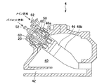
次に、図2及び図3を参照して、一実施形態に係る燃焼器4の詳細な構成について説明する。なお、図2は、一実施形態に係る燃焼器4を示す断面図である。図3は、一実施形態に係る燃焼器4の要部を示す断面図である。 Next, with reference to FIG.2 and FIG.3, the detailed structure of the combustor 4 which concerns on one Embodiment is demonstrated. FIG. 2 is a cross-sectional view showing the combustor 4 according to an embodiment. FIG. 3 is a cross-sectional view showing a main part of the combustor 4 according to one embodiment.
図2及び図3に示すように、一実施形態に係る燃焼器4は、ロータ8を中心として環状に複数配置されている(図1参照)。各燃焼器4は、ケーシング20により画定される燃焼器車室40に設けられた燃焼器ライナ46と、燃焼器ライナ46内にそれぞれ配置されたパイロット燃焼バーナ50及び複数のメイン燃焼バーナ(予混合燃焼バーナ)60と、を含む。なお、燃焼器4は、燃焼ガスをバイパスさせるためのバイパス管(不図示)等の他の構成要素を備えていてもよい。
As shown in FIG.2 and FIG.3, the combustor 4 which concerns on one Embodiment is arrange | positioned circularly centering | focusing on the rotor 8 (refer FIG. 1). Each combustor 4 includes a
例えば、燃焼器ライナ46は、パイロット燃焼バーナ50及び複数のメイン燃焼バーナ60の周囲に配置される内筒46aと、内筒46aの先端部に連結された尾筒46bと、を有している。
パイロット燃焼バーナ50は、燃焼器ライナ46の中心軸に沿って配置されている。そして、パイロット燃焼バーナ50を囲むように、複数のメイン燃焼バーナ60が互いに離間して配列されている。
パイロット燃焼バーナ50は、燃料ポート52に連結されたパイロットノズル(ノズル)54と、パイロットノズル54を囲むように配置されたパイロットバーナ筒56と、パイロットノズル54の外周に設けられたスワラ58と、を有している。なお、パイロット燃焼バーナ50の具体的な構成については後述する。
メイン燃焼バーナ60は、燃料ポート62に連結されたメインノズル(ノズル)64と、メインノズル64を囲むように配置されたメインバーナ筒66と、メインノズル64の外周に設けられたスワラ68と、を有している。
For example, the
The
The
The
上記構成を有する燃焼器4において、圧縮機2で生成された高温高圧の圧縮空気は車室入口42から燃焼器車室40内に供給され、さらに燃焼器車室40からメインバーナ筒66内に流入する。そして、この圧縮空気と、燃料ポート62から供給された燃料とがメインバーナ筒66内で予混合される。この際、予混合気はスワラ68により主として旋回流を形成し、燃焼器ライナ46に流れ込む。また、圧縮空気と、燃料ポート52を介してパイロット燃焼バーナ50から噴射された燃料とが燃焼器ライナ46で混合され、図示しない種火により着火されて燃焼し、燃焼ガスが発生する。このとき、燃焼ガスの一部が火炎を伴って周囲に拡散することで、各メイン燃焼バーナ60から燃焼器ライナ46内に流れ込んだ予混合気に着火されて燃焼する。すなわち、パイロット燃焼バーナ50から噴射されたパイロット燃料によるパイロット火炎によって、メイン燃焼バーナ60からの予混合気(予混合燃料)の安定燃焼を行うための保炎を行うことができる。
In the combustor 4 having the above-described configuration, the high-temperature and high-pressure compressed air generated by the
以下、本実施形態に係る燃焼バーナの構成について、一例として上述したパイロット燃焼バーナ50を用いて詳細に説明する。
なお、本実施形態に係る燃焼バーナは、パイロット燃焼バーナ50に限定されるものではなく、ノズルの周囲の軸方向流路にスワラ(スワラベーン)が設けられた燃焼バーナであればどのタイプの燃焼バーナに対しても適用可能である。例えば、燃焼バーナは、ガスタービン1の燃焼器4に設けられるメイン燃焼バーナ60であってもよいし、ガスタービン1以外の機器に設けられる燃焼バーナであってもよい。
Hereinafter, the configuration of the combustion burner according to the present embodiment will be described in detail using the
Note that the combustion burner according to this embodiment is not limited to the
一実施形態に係る燃焼バーナ(パイロット燃焼バーナ)50の概略的な基本構成を図4及び図5に示す。ここで、図4は幾つかの実施形態に係る燃焼バーナ50の概略的な基本構成を示す断面図である。なお、同図はノズル54の軸方向に沿った断面図である。図4では、理解を容易にするために、ノズル54の下方に位置するスワラ58はノズル軸方向に沿った断面を示すが、ノズル54の上方に位置するスワラベーン70はその側面図を示している。図5は図4に示される燃焼バーナのX−X線断面図である。
一実施形態に係る燃焼バーナ50は、ノズル(燃料ノズル)54と、パイロットバーナ筒56と、スワラ58と、仕切り板100と、を備えている。
4 and 5 show a schematic basic configuration of a combustion burner (pilot combustion burner) 50 according to an embodiment. Here, FIG. 4 is a cross-sectional view showing a schematic basic configuration of a
The
ノズル54は、例えば上述したように燃料ポート52(図2及び図3参照)に連結され、燃料ポート52から燃料が供給される。なお、燃料は、気体であっても液体であってもよく、その種類も特に限定されない。また、パイロットノズル54には、例えば燃料ガス及び燃料油のように、2種類以上の燃料が供給されてもよい。
The
パイロットバーナ筒56は、ノズル54に対して同心状に、且つノズル54の少なくとも先端側を囲むように配置されている。すなわち、パイロットバーナ筒56の軸はノズル54の軸と略一致し、且つパイロットバーナ筒56の径はノズル54の径よりも大きい。パイロットバーナ筒56は、ノズル54の周囲の上流側領域においては壁面がノズル54の軸方向に沿った円筒状に形成され、火炎面側に位置する下流側領域においては壁面が端部に向けて拡径する円錐台形状に形成されてもよい。なお、本実施形態において、上流側とは、空気又は燃料の流れる向きにおける上流側をいい、下流側とは、空気又は燃料の流れる向きにおける下流側をいう。
ノズル54の外周面とパイロットバーナ筒56の内周面との間には、ノズル54の周囲において該ノズル54の軸方向に沿って延在する環状の空気流路90が形成されている。この空気流路90には、その上流側(図4において左側)から下流側(図4において右側)に向かって、空気が流通する。空気は圧縮空気であってもよい。また、空気流路90に供給される空気は、燃料を含まない空気であってもよい。
The
Between the outer peripheral surface of the
スワラ58は、空気流路90を流通する気体を旋回させるように構成され、少なくとも一枚のスワラベーン70を備える。なお、図4及び図5に例示したスワラ58は、ノズル54を中心として放射状に配列された8枚のスワラベーン70を有している。
The
スワラベーン70は、ノズル54の周囲においてノズル54の軸方向に沿って延在する空気流路90に設けられ、空気流路90を流通する気体に旋回力を付与するように構成されている。スワラベーン70は、平面視において翼型形状を有する流線形であってもよい。
また、スワラベーン70は、ノズル54側に位置する翼根部71と、翼根部71よりも外周側に位置する翼本体部72と、を有している。具体的に、翼根部71はスワラベーン70の外周面に立設しており、翼根部71によって翼本体部72がノズル54に連結される。また、翼根部71は、ノズル54の軸方向における長さが翼本体部72より短い。
さらに、図9に示すように、スワラベーン70は、圧力面である腹面73と、負圧面である背面74と、気体の流通方向(ノズル54の軸方向)における上流側の端部である前縁75と、下流側の端部である後縁76と、を有している。なお、図9については後に詳述するが、同図は一実施形態におけるスワラベーン70A及び仕切り板100Aの分解斜視図である。
The
Further, the
Further, as shown in FIG. 9, the
図4及び図5に戻り、スワラベーン70には、少なくとも一つの燃料噴射孔78が形成されている。本実施形態では一例として、スワラベーン70の腹面73に1個の燃料噴射孔78が形成された構成を示している。他の構成として、スワラベーン70の腹面73又は背面74(図9参照)に複数の燃料噴射孔78が形成されていてもよい。燃料と空気の予混合を促進する目的から、少なくとも一つの燃料噴射孔78はスワラベーン70の上流側領域に設けられていてもよい。
Returning to FIG. 4 and FIG. 5, at least one
ノズル54及びスワラベーン70の内部には、それぞれ、燃料ポート52(図2及び図3参照)から供給された燃料を流通させるための燃料流路が設けられている。
一構成例において、燃料流路は、予混合燃焼用燃料流路80と、拡散燃焼用燃料流路85(図5及び図6参照)と、スワラ内燃料流路79と、を含む。
Inside the
In one configuration example, the fuel flow path includes a premixed combustion
予混合燃焼用燃料流路80は、ノズル54の内部に設けられており、ノズル54の軸方向に沿った上流側流路81及び下流側流路82と、上流側流路81及び下流側流路82の間に設けられたキャビティ83と、を有している。下流側流路82は、スワラ内燃料流路79に連通している。
スワラ内燃料流路79は、スワラベーン70の内部(例えば翼根部71の内部)に設けられており、スワラベーン70の燃料噴射孔78に連通している。
予混合燃焼用燃料流路80に供給された燃料は、上流側流路81、キャビティ83、下流側流路82を順に通って、スワラベーン70の燃料噴射孔78から空気流路90に噴射される。そして、燃料噴射孔78から噴射された燃料は、空気流路90を流れる空気と混合されて予混合気(燃料ガス)となり、燃焼空間に送られて燃焼する。なお、燃焼空間とは、ノズル54の後流側の領域であって、パイロットバーナ筒56で囲まれた空間を含む。
The premixed combustion
The intra-swirler
The fuel supplied to the premixed combustion
拡散燃焼用燃料流路85は、図6に示すように、ノズル54の軸方向に沿って該ノズル54の内部に設けられており、ノズル内燃料流路86と、ノズル内燃料流路86に連通するキャビティ87と、を有している。ノズル内燃料流路86は、ノズル54の下流側端部に形成された燃料噴射孔88に連通している。なお、図4において拡散燃焼用燃料流路85は図示されないため、図6のノズル下方部分において拡散燃焼用燃料流路85を含む他の断面を示している。また、他の構成例においては、拡散燃焼用燃料流路85がノズル54の中心に設けられていてもよい。
拡散燃焼用燃料流路85に供給された燃料は、キャビティ87及びノズル内燃料流路86を通って、燃料噴射孔88から燃焼空間内に噴射される。そして、燃料噴射孔88から噴射された燃料は、燃焼空間において空気又は予混合気と混合されて燃焼する。
As shown in FIG. 6, the diffusion combustion
The fuel supplied to the diffusion combustion
図4及び図5に戻り、仕切り板100は、ノズル54を囲むように環状に形成されている。例えば、仕切り板100は、複数の部材を溶接等によって接合することにより環状に形成されてもよいし、一つの部材によって環状に形成されてもよい。
また、仕切り板100は、ノズル54の半径方向において空気流路90のうち少なくともスワラベーン70の下流側の領域を仕切り、空気流路90のうち少なくとも前記領域を、ノズル54の外周面に面する内側流路92と該内側流路92に対して半径方向の外側に位置する外側流路91とに分割するように構成されている。
Returning to FIG. 4 and FIG. 5, the
In addition, the
外側流路91には、スワラベーン70に形成された燃料噴射孔78が位置している。さらに、仕切り板100の上流側端部101は、ノズル54の軸方向において、燃料噴射孔78よりも上流側に位置している。
一実施形態においては、図4に示すように、内側流路92内には燃料噴射孔が存在しない。すなわち、内側流路92内には、ノズル54内の外周面にもスワラベーン70にも燃料噴射孔は設けられていない。また、一実施形態においては、空気流路90に供給される空気は、燃料を含まない空気である。
A
In one embodiment, there are no fuel injection holes in the
図4に示す例では、仕切り板100は、スワラベーン70の上流側から下流側までの全ての領域を仕切るように構成されている。
あるいは、仕切り板100の上流側端部101が、スワラベーン70の前縁75(図9参照)よりも下流側に位置してもよい。この場合も、仕切り板100の上流側端部101は、ノズル54の軸方向において、燃料噴射孔78よりも上流側に位置するものとする。
In the example illustrated in FIG. 4, the
Or the
上記実施形態によれば、仕切り板100によって空気流路90のうち少なくとも下流側の領域を内側流路92と外側流路91とに仕切り、内側流路92を流れる空気によってノズル54の外周面を覆うフィルム空気層を形成している。さらに、外側流路91内に形成された燃料噴射孔78が仕切り板100よりも上流側に位置するように構成したので、燃料噴射孔78から噴射された燃料が内側流路92におけるフィルム空気層へ混入することを防止でき、フラッシュバックの発生を効果的に抑制できる。
According to the above embodiment, the
さらに、本実施形態に係る燃焼バーナ50は以下の構成を選択的に備えていてもよい。
Furthermore, the
幾つかの実施形態では、燃焼バーナ50は、空気流路90に燃料を噴射するための複数の燃料噴射部を備えており、複数の燃料噴射部のうち最も上流側に位置する燃料噴射部がスワラベーン70の燃料噴射孔78である。すなわち、燃料噴射部は、スワラベーン70の燃料噴射孔78とは別に、例えば図6に示す燃料噴射孔88のように他の燃料噴射部を備えていてもよい。但し、他の燃料噴射部は、スワラベーン70の燃料噴射孔78よりも下流側に位置する。また、燃料噴射部は仕切り板100が設けられた軸方向範囲内に位置していてもよいが、この場合、燃料噴射部は外側流路91のみに燃料を噴射するようになっている(すなわち、内側流路92には燃料を噴射しない)。
In some embodiments, the
一実施形態において、図5に示すように、仕切り板100は、少なくとも一部が、周方向に隣り合う一対のスワラベーン70のうち一方の腹面73と、一対のスワラベーン70の他方の背面74との間において周方向に延在している。この構成によって、内側流路92は、仕切り板100、ノズル54の外周面、スワラベーン70の腹面73及び背面74によって囲まれた翼間流路92Aが形成される。この翼間流路92Aは、内側流路92の少なくとも一部である。
上記構成によって、ノズル54の外周面から半径方向外側に延在するようにスワラベーン70が設けられる場合であっても、隣接するスワラベーン70間において、仕切り板100によって外側流路91から隔離された翼間流路92Aを形成することができる。これにより、外側流路91内に位置する燃料噴射孔78から噴射された燃料が翼間流路92Aに混入することを防止できる。
In one embodiment, as shown in FIG. 5, the
Even if the
幾つかの実施形態では、ノズル54の下流側端部55(実際には下流側端部55を含むノズル下流側領域)において、ノズル54の外周面は該ノズル54の軸方向に沿っている。すなわち、ノズル54の下流側領域における該ノズル54の外周面は、軸方向において径が略同一の円筒状に形成されている。一方、仕切り板100は、ノズル54の下流端の端部における外周面を覆うように軸方向に沿って延在している。この仕切り板100も、ノズル54の下流側領域では、軸方向において径が略同一の円筒状に形成されている。この構成によって、ノズル54の外周面と仕切り板100の内周面との間の距離は、ノズル54の軸方向において概ね一定となる。また、図4に示す例では、仕切り板100の下流側端部102とノズル54の下流側端部55とは、軸方向位置が一致している。但し、仕切り板100の下流側端部102とノズル54の下流側端部55との軸方向位置の関係は上記構成に限定されるものではない。
In some embodiments, the outer peripheral surface of the
例えば、ノズル54の外周面が軸方向に沿って延在しておらず、ノズル54の外周面が先細りになっている場合、内側流路92を通過する空気流は流路断面積の拡大に伴って軸流速度が低下してしまうおそれがある。この点、上記実施形態によれば、ノズル54の下流側の端部において、ノズル54の外周面がノズル54の軸方向に沿っており、且つ、軸方向に沿って延在する仕切り板100によって覆われることで、空気流の軸流速度を高く維持したまま内側流路92内を空気が通過することになる。よって、内側流路92の後流側の領域に向かう火炎の遡上を抑制することができる。
また、後述するように、内側流路92内における空気流が旋回成分を有する場合、仕切り板100の内壁面に空気流が押し付けられて、仕切り板100の内壁面近傍に形成される境界層が薄くなり、仕切り板100の内壁面近傍における軸流速度が大きくなる。よって、特に仕切り板100の後流側の領域への火炎の遡上を抑制することができる。
For example, when the outer peripheral surface of the
Further, as will be described later, when the air flow in the
図4に示すように燃焼バーナ50は、内側流路92の内部においてノズル54の周方向に複数設けられ、仕切り板100をノズル54に支持する支持部材110をさらに備えてもよい。支持部材110は、仕切り板100の内周面とノズル54の外周面との間に位置する。このように支持部材110を設けることによって、ノズル54に対して仕切り板100を強固に支持できる。
一実施形態では、各々の支持部材110はスワラベーン70の後流側に位置する。これにより、内側流路92における空気の流れに支持部材110が及ぼす影響を低減できる。各々の支持部材110は、スワラベーン70の後流側に隙間93を介して位置してもよい。
As shown in FIG. 4, the
In one embodiment, each
幾つかの実施形態に係る燃焼バーナ50は、上記実施形態で説明した基本的な構成に加えて、以下の構成をさらに備えていてもよい。図6〜図8は、主としてノズル54及び仕切り板100の変形例を示し、図9〜図11A,図11Bは、主としてスワラベーン70及び仕切り板100の変形例を示している。なお、図6〜図11A,図11Bにおいて、同一の部位については同一の符号を付している。
The
図6は、一実施形態に係る燃焼バーナ50Aのノズル軸方向に沿った断面図である。
一実施形態に係る燃焼バーナ50Aでは、仕切り板100の下流側端部102は、ノズル54Aの軸方向において、ノズル54Aの下流側端部55Aの端面よりも上流側に位置する。すなわち、燃焼バーナ50Aは、ノズル54Aの下流側端部55Aが仕切り板100よりも下流側に突出した構成となっている。具体的に、下流側端部55Bは、軸方向において略同一の径を有する円筒状に形成されており、突出した部位も円筒状に形成されている。
この場合、ノズル54Aの下流側端部55Aは仕切り板100によって覆われないので、内側流路92を通過した空気の流れが、仕切り板100の後流側において巻き上がって渦を形成する。この渦によって、仕切り板100の後流側における燃料濃度が低下するため、仕切り板100の下流側端部102に向かう火炎の遡上を抑制できる。
FIG. 6 is a cross-sectional view along the nozzle axis direction of the
In the
In this case, since the
図7は、他の実施形態に係る燃焼バーナ50Bのノズル軸方向に沿った断面図である。
他の実施形態に係る燃焼バーナ50Bでは、仕切り板100の下流側端部102は、ノズル54Bの軸方向において、ノズル54Bの下流側端部55Bの端面よりも上流側に位置する。すなわち、燃焼バーナ50Bは、ノズル54Bの下流側端部55Bが仕切り板100よりも下流側に突出した構成となっている。また、ノズル54Bの下流側端部55Bは、仕切り板100の下流側端部102よりも下流側において、ノズル54Bの下流側の端面に近づくにつれて、ノズル54Bの半径方向においてノズル54Bの中心軸から遠ざかるように軸方向に対して傾斜した外周面(傾斜面)57を有する。すなわち、仕切り板100よりも下流側に突出したノズル54Bの下流側端部55Bが、下流側に向けて拡径した形状となっている。なお、「傾斜」とは、直線状に傾斜している場合(傾斜面57が直線)の他に、軸方向に傾斜した接線をもって湾曲している場合(傾斜面57が湾曲した曲線)も含む。
上記実施形態によれば、ノズル54Bの下流側端部55Bにおいて、内側流路92を通過した空気流がノズル54Bの外周面に押し付けられて、ノズル54Bの外周面近傍の境界層が薄くなる。そのため、ノズル54Bの外周面近傍における軸流速度分布を均一に近づけることができ、フラッシュバックを抑制可能となる。
FIG. 7 is a cross-sectional view along the nozzle axis direction of a
In the
According to the above embodiment, the air flow that has passed through the
図8は、他の実施形態に係る燃焼バーナ50Cのノズル軸方向に沿った要部断面図である。
幾つかの実施形態に係る燃焼バーナ50Cにおいて、ノズル54Cは、ノズル内部流路84と、空気噴射孔89と、をさらに含む。
ノズル内部流路84は、ノズル54Cの内部に設けられ、内側流路92に連通するように構成されている。図8に示す例では、ノズル内部流路84の入口は、ノズル54Cと支持部材110との間の隙間93に開口しており、ノズル内部流路84の出口は、ノズル54Cの下流側端部55Cの端面に開口した空気噴射孔89である。内側流路92から分岐されてノズル内部流路84を流通する空気は、空気噴射孔89からノズル54Cの後流側の燃焼空間内に噴射される。一実施形態では、ノズル内部流路84の上流側はノズル54Cの軸方向に沿って形成され、ノズル内部流路84の下流側はノズル54Cの内側に向けて傾斜していてもよい。この場合、ノズル内部流路84を流通する空気は、空気噴射孔89からノズル54Cの径方向内側へ向けて噴射される。
FIG. 8 is a cross-sectional view of a main part along the nozzle axis direction of a
In the
The nozzle
このように、内側流路92を流れる空気の一部を、ノズル内部流路84を介して空気噴射孔89からノズル54の後流側に噴射するようにしたので、ノズル54の下流側の端面が空気で覆われて燃料濃度の低い領域が形成される。これにより、ノズル54の下流側の端面に火炎が遡上し難くなり、ノズル54の焼損を防止できる。
As described above, since a part of the air flowing through the
図9は、一実施形態におけるスワラベーン70A及び仕切り板100Aの分解斜視図である。
一実施形態において、スワラベーン70Aは、翼本体部72A及び翼根部71Aを含む。仕切り板100Aは、上流側端部101と、下流側端部102と、円筒部104と、翼間部105と、凹部106Aと、を含む。
FIG. 9 is an exploded perspective view of the
In one embodiment, the
この実施形態においては、スワラベーン70Aの内側流路92(図4及び図5参照)における空気の旋回方向122が、外側流路91における空気の旋回方向120と同じである。すなわち、内側流路92にも旋回部が設けられており、この旋回部によって内側流路に流れる空気に外側流路91における空気の旋回方向120と同じ方向の旋回をかけるようになっている。
一構成例では、内側流路92を通過する空気を旋回させるための旋回部が、仕切り板100Aをノズル54(図4及び図5参照)に支持するための支持部材110Aである。この場合、支持部材110Aは、平面視において翼型形状を有する流線形であってもよいし、より簡素化された構成としてルーバーのような傾斜板としてもよく、その構成は特に限定されない。スワラベーン70Aと、支持部材110Aとは別体で構成され、互いに離間して配置されてもよい。例えば、支持部材110Aは、隙間93をあけてスワラベーン70Aの後流側に配置される。
In this embodiment, the
In one configuration example, the swivel portion for swirling the air passing through the
上記実施形態によれば、仕切り板100Aの後流側における内側流路92(図4及び図5参照)の空気と外側流路91の空気とが合流する領域において互いの旋回方向120,122が同じであるため、外側流路91を通過した燃料を含む空気が内側流路92を通過した空気に混入し難くなる。これにより、仕切り板100Aの内壁面近傍に形成される境界層の影響により軸流速度が小さい領域(仕切り板100Aの後流側の領域)における燃料濃度を低下させ、該領域への火炎の遡上を抑制できる。また、支持部材110Aが内側流路92の空気の流れを阻害することなく旋回流を形成する構成となっているため、仕切り板100Aの支持のみならず旋回流形成の観点からも支持部材110Aを有効に活用できる。
According to the above embodiment, in the region where the air in the inner flow path 92 (see FIGS. 4 and 5) and the air in the
また、図示しないが、他の実施形態において、内側流路92(図4及び図5参照)における空気の流れは、ノズル54の軸方向に沿った流れ、又は、外側流路91における空気の旋回方向120(図9参照)と逆方向の旋回成分を持つ流れである。
上記実施形態によれば、仕切り板100の後流側において内側流路92を通過する空気の旋回が弱められ、内側流路92の後流側における空気の軸流速度を高めることができる。このため、ノズル54後端面への火炎の遡上(渦芯フラッシュバック)を抑制できる。
Although not shown, in other embodiments, the air flow in the inner flow path 92 (see FIGS. 4 and 5) is the flow along the axial direction of the
According to the embodiment, the swirling of the air passing through the
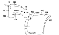
図11Aにおいて、仕切り板100Aの下流側端部102側は、周方向に連続した円筒部104であり、仕切り板100Aの上流側端部101側に、スワラベーン70Aの翼根部71Aが係合する凹部106Aが設けられていてもよい。ノズル54の周方向に複数のスワラベーン70Aが設けられている場合には、複数のスワラベーン70Aの各々に対応して、仕切り板100Aに複数の凹部106Aが形成されている。複数の凹部106Aは、ノズル54の周方向において互いに離間して複数形成されている。
また、仕切り板100Aの上流側端部101は、例えばベルマウス形状のように、上流側へ向けて拡径した形状であってもよい。図示される例では、仕切り板100Aの上流側端部101は凹部106Aによって断続的に形成された翼間部105となっており、この翼間部105が、軸方向において上流側へ向けて拡径した構成となっている。
なお、仕切り板100Aは、スワラベーン70Aに対して一体的に形成されている。例えば、仕切り板100Aとスワラベーン70Aとが溶接等によって接合されて一体的に形成されてもよいし、仕切り板100Aとスワラベーン70Aとが嵌め込みによって一体的に形成されてもよい。あるいは、仕切り板100Aとスワラベーン70Aとが一つの部材によって形成されてもよい。
不図示の他の構成例では、仕切り板100(図4及び図5参照)がスワラベーン70の前縁75よりも上流側まで延在し、スワラベーン70の前縁75よりも上流側において仕切り板100が閉じていてもよい。すなわち、仕切り板100が、スワラベーンの全周を囲むように設けられていてもよい。
In FIG. 11A, the
Further, the
The
In another configuration example not shown, the partition plate 100 (see FIGS. 4 and 5) extends to the upstream side of the
図10は、他の実施形態におけるスワラベーン70B及び仕切り板100Bの分解斜視図である。ここでは、図9と異なる構成のみ説明する。
他の実施形態において、スワラベーン70Bは、翼本体部72B及び翼根部71Bを含む。仕切り板100Bは、上流側端部101と、下流側端部102と、円筒部104と、翼間部105と、凹部106Bと、を含む。
FIG. 10 is an exploded perspective view of the
In another embodiment, the
この実施形態において、支持部材110Bは、内側流路92(図4及び図5参照)を流れる空気に、外側流路91を流れる空気と同じ方向120に旋回をかけるように構成されている。支持部材110Bは、スワラベーン70Bと一体的に形成されている。すなわち、翼根部71Bにおいてスワラベーン70Bと支持部材110Bは連結している。例えば支持部材110Bは、スワラベーン70Bと同一の部材によって一体成形されていてもよいし、スワラベーン70Bとは別の部材を溶接等で接合することによって一体的に形成してもよい。
In this embodiment, the
図11A及び図11Bは、他の実施形態におけるスワラベーン及び仕切り板の分解斜視図である。
図11Aに示す実施形態において、スワラベーン70Cは、翼本体部72C及び翼根部71Cを含む。仕切り板100Cは、上流側端部101と、下流側端部102と、円筒部104と、翼間部105と、凹部106Cと、を含む。
この実施形態においては、仕切り板100Cとノズル54(図4及び図5参照)の間に位置する支持部材は存在しないが、内側流路92に位置する旋回部114が設けられている。旋回部114は、翼本体部72Cとは異なる形状であるが、外側流路91の旋回方向120と同じ方向又は逆の方向に空気を旋回するように構成される。仕切り板100Cの上流側端部101側に設けられた凹部106Cは、旋回部114及び翼根部71Cに係合するような形状となっている。
11A and 11B are exploded perspective views of a swirler vane and a partition plate according to another embodiment.
In the embodiment shown in FIG. 11A, the
In this embodiment, there is no support member positioned between the
図11Bに示す実施形態において、スワラベーン70Dは、翼本体部72D及び翼根部71Dを含む。仕切り板100Dは、上流側端部101と、下流側端部102と、円筒部104と、翼間部105と、凹部106Dと、を含む。
この実施形態においては、仕切り板100Dとノズル54(図4及び図5参照)の間に位置する支持部材は存在しない。また、スワラベーン70Dは、ノズル54の径方向に同一の翼型を有している。仕切り板100Dの上流側端部101側に設けられた凹部106Dは、スワラベーン70Dに係合するような形状となっている。
In the embodiment shown in FIG. 11B, the
In this embodiment, there is no support member located between the
上述したように、本発明の実施形態によれば、スワラベーン70,70A〜70Dの燃料噴射孔78から噴射された燃料が空気流路90のうち内側流路92に混入することを防止でき、フラッシュバックの発生を効果的に抑制できる。
As described above, according to the embodiment of the present invention, the fuel injected from the fuel injection holes 78 of the
本発明は上述した実施形態に限定されることはなく、上述した実施形態に変形を加えた形態や、これらの形態を適宜組み合わせた形態も含む。
例えば、上記実施形態では、燃焼バーナとしてパイロット燃焼バーナ60を例示して説明したが、本発明の実施形態は、予混合燃焼バーナ50に対しても適用可能である。また、上記実施形態では、主として2次元翼を例示しているが、本発明の実施形態は、3次元翼にも適用可能である。
The present invention is not limited to the above-described embodiments, and includes forms obtained by modifying the above-described embodiments and forms obtained by appropriately combining these forms.
For example, in the above-described embodiment, the
なお、上記実施形態において、例えば、「ある方向に」、「ある方向に沿って」、「平行」、「直交」、「中心」、「同心」或いは「同軸」等の相対的或いは絶対的な配置を表す表現は、厳密にそのような配置を表すのみならず、公差、若しくは、同じ機能が得られる程度の角度や距離をもって相対的に変位している状態も表すものとする。
例えば、「同一」、「等しい」及び「均質」等の物事が等しい状態であることを表す表現は、厳密に等しい状態を表すのみならず、公差、若しくは、同じ機能が得られる程度の差が存在している状態も表すものとする。
例えば、四角形状や円筒形状等の形状を表す表現は、幾何学的に厳密な意味での四角形状や円筒形状等の形状を表すのみならず、同じ効果が得られる範囲で、凹凸部や面取り部等を含む形状も表すものとする。
一方、一の構成要素を「備える」、「含む」、又は、「有する」という表現は、他の構成要素の存在を除外する排他的な表現ではない。
In the above embodiment, for example, “in a certain direction”, “along a certain direction”, “parallel”, “orthogonal”, “center”, “concentric” or “coaxial” or the like is relative or absolute. The expression representing the arrangement not only strictly represents such an arrangement, but also represents a state of relative displacement with a tolerance or an angle or a distance at which the same function can be obtained.
For example, an expression indicating that things such as “identical”, “equal”, and “homogeneous” are in an equal state not only represents an exactly equal state, but also has a tolerance or a difference that can provide the same function. It also represents the existing state.
For example, expressions representing shapes such as quadrangular shapes and cylindrical shapes represent not only geometrically strict shapes such as quadrangular shapes and cylindrical shapes, but also irregularities and chamfers as long as the same effects can be obtained. A shape including a part or the like is also expressed.
On the other hand, the expression “comprising”, “including”, or “having” one constituent element is not an exclusive expression that excludes the presence of the other constituent elements.
1 ガスタービン
2 圧縮機
4 燃焼器
6 タービン
10 圧縮機車室
22 タービン車室
28 排気車室
30 排気室
40 燃焼器車室
46 燃焼器ライナ
50,50A〜50C 燃焼バーナ(パイロット燃焼バーナ)
52 燃料ポート
54,54A〜54C ノズル(パイロットノズル)
56 パイロットバーナ筒
57 外周面(傾斜面)
58 スワラ
60 メイン燃焼バーナ
62 燃料ポート
64 ノズル(メインノズル)
66 メインバーナ筒
70,70A〜70D スワラベーン
71,71A〜71D 翼根部
72,72A〜72D 翼本体部
78 燃料噴射孔
79 スワラ内燃料流路
84 ノズル内部流路
88 燃料噴射孔
89 空気噴射孔
90 空気流路
91 外側流路
92 内側流路
92A 翼間流路
93 隙間
100,100A〜100D 仕切り板
110,110A,110B 支持部材
DESCRIPTION OF SYMBOLS 1
52
56
58
66
Claims (12)
燃料を噴射するための燃料噴射孔を有するとともに、前記ノズルの周囲において前記ノズルの軸方向に沿って延在する環状の空気流路に設けられて該空気流路を流れる空気を旋回させるように構成されたスワラベーンと、
前記ノズルの半径方向において前記空気流路のうち少なくとも前記スワラベーンの下流側の領域を仕切り、前記空気流路のうち少なくとも前記領域を、前記ノズルの外周面に面する内側流路と該内側流路に対して前記半径方向の外側に位置する外側流路とに分割する環状の仕切り板と、を備え、
前記燃料噴射孔は、前記スワラベーンのうち前記空気流路の前記外側流路内に位置する部位にのみ設けられ、
前記燃料噴射孔は、前記空気流路の前記外側流路内に位置し、
前記仕切り板の上流側の端部は、前記軸方向において、前記燃料噴射孔よりも上流側に位置し、
前記ノズルは、
前記ノズルの内部に設けられ、前記内側流路に連通するノズル内部流路と、
前記ノズルの下流側の端面に開口し、前記ノズル内部流路からの前記空気を噴射するための空気噴射孔と、
を含む
ことを特徴とする燃焼バーナ。 A nozzle,
It has a fuel injection hole for injecting fuel, and is provided in an annular air passage extending around the nozzle along the axial direction of the nozzle so as to swirl the air flowing through the air passage A structured swirl vane,
Partitioning at least a region downstream of the swirler vane in the radial direction of the nozzle in the radial direction of the nozzle; and at least the region of the air channel, an inner channel facing the outer peripheral surface of the nozzle and the inner channel An annular partition plate that divides into an outer flow path located outside in the radial direction with respect to
The fuel injection hole is provided only in a portion of the swirler vane located in the outer flow path of the air flow path,
The fuel injection hole is located in the outer flow path of the air flow path,
The upstream end of the partition plate is located upstream of the fuel injection hole in the axial direction,
The nozzle is
A nozzle internal flow path provided in the nozzle and communicating with the inner flow path;
An air injection hole for injecting the air from the nozzle internal flow path, opening to the downstream end face of the nozzle;
Combustion burner characterized by including.
前記仕切り板は、前記ノズルの下流端の端部における前記外周面を覆うように前記軸方向に沿って延在していることを特徴とする請求項1乃至3の何れか一項に記載の燃焼バーナ。 At the downstream end of the nozzle, the outer peripheral surface of the nozzle is along the axial direction,
The said partition plate is extended along the said axial direction so that the said outer peripheral surface in the edge part of the downstream end of the said nozzle may be covered, The Claim 1 thru | or 3 characterized by the above-mentioned. Burning burner.
各々の前記スワラベーンは、前記ノズルの外周面から前記半径方向の外側に延在しており、
前記仕切り板は、少なくとも一部が、周方向に隣り合う一対のスワラベーンのうち一方の腹面と、前記一対のスワラベーンの他方の背面との間において前記周方向に延在しており、
前記内側流路は、前記仕切り板、前記ノズルの外周面、前記腹面及び前記背面によって囲まれた翼間流路を含むことを特徴とする請求項1乃至8の何れか一項に記載の燃焼バーナ。 A plurality of the swirler vanes are provided in the circumferential direction of the nozzle,
Each swirler vane extends from the outer peripheral surface of the nozzle to the outside in the radial direction,
At least a part of the partition plate extends in the circumferential direction between one abdominal surface of a pair of swirler vanes adjacent in the circumferential direction and the other back surface of the pair of swirler vanes,
The combustion according to any one of claims 1 to 8, wherein the inner flow path includes an inter-blade flow path surrounded by the partition plate, the outer peripheral surface of the nozzle, the abdominal surface, and the back surface. Burner.
燃料を噴射するための燃料噴射孔を有するとともに、前記ノズルの周囲において前記ノズルの軸方向に沿って延在する環状の空気流路に設けられて該空気流路を流れる空気を旋回させるように構成されたスワラベーンと、It has a fuel injection hole for injecting fuel, and is provided in an annular air passage extending around the nozzle along the axial direction of the nozzle so as to swirl the air flowing through the air passage A structured swirl vane,
前記ノズルの半径方向において前記空気流路のうち少なくとも前記スワラベーンの下流側の領域を仕切り、前記空気流路のうち少なくとも前記領域を、前記ノズルの外周面に面する内側流路と該内側流路に対して前記半径方向の外側に位置する外側流路とに分割する環状の仕切り板と、を備え、Partitioning at least a region downstream of the swirler vane in the radial direction of the nozzle in the radial direction of the nozzle; and at least the region of the air channel, an inner channel facing the outer peripheral surface of the nozzle and the inner channel An annular partition plate that divides into an outer flow path located outside in the radial direction with respect to
前記燃料噴射孔は、前記空気流路の前記外側流路内に位置し、The fuel injection hole is located in the outer flow path of the air flow path,
前記仕切り板の上流側の端部は、前記軸方向において、前記燃料噴射孔よりも上流側に位置し、The upstream end of the partition plate is located upstream of the fuel injection hole in the axial direction,
前記ノズルは、The nozzle is
前記ノズルの内部に設けられ、且つ、前記スワラベーンの後流側において前記内側流路に連通するノズル内部流路と、A nozzle internal channel that is provided inside the nozzle and communicates with the inner channel on the downstream side of the swirler vane;
前記ノズルの下流側の端面に開口し、前記ノズル内部流路からの前記空気を噴射するための空気噴射孔と、An air injection hole for injecting the air from the nozzle internal flow path, opening to the downstream end face of the nozzle;
を含むincluding
ことを特徴とする燃焼バーナ。Combustion burner characterized by that.
前記燃焼バーナからの燃焼ガスを導くための流路を形成するための燃焼ライナと、を備えることを特徴とする燃焼器。 A combustion burner according to any one of claims 1 to 10 ,
And a combustion liner for forming a flow path for introducing combustion gas from the combustion burner.
前記圧縮機からの前記圧縮空気により燃料を燃焼させて燃焼ガスを発生させるように構成された請求項11に記載の燃焼器と、
前記燃焼器からの前記燃焼ガスによって駆動されるように構成されたタービンと、を備えることを特徴とするガスタービン。
A compressor for generating compressed air;
The combustor according to claim 11 , configured to generate a combustion gas by burning fuel with the compressed air from the compressor;
And a turbine configured to be driven by the combustion gas from the combustor.
Priority Applications (6)
| Application Number | Priority Date | Filing Date | Title |
|---|---|---|---|
| JP2014190634A JP6430756B2 (en) | 2014-09-19 | 2014-09-19 | Combustion burner and combustor, and gas turbine |
| DE112015004249.0T DE112015004249B4 (en) | 2014-09-19 | 2015-08-18 | BURNER, COMBUSTOR AND GAS TURBINE |
| KR1020177005483A KR101892879B1 (en) | 2014-09-19 | 2015-08-18 | Combustion burner, combustor, and gas turbine |
| US15/511,346 US10415830B2 (en) | 2014-09-19 | 2015-08-18 | Combustion burner, combustor, and gas turbine |
| PCT/JP2015/073122 WO2016042960A1 (en) | 2014-09-19 | 2015-08-18 | Combustion burner, combustor, and gas turbine |
| CN201580030364.7A CN106461223B (en) | 2014-09-19 | 2015-08-18 | Burner, burner and gas turbine |
Applications Claiming Priority (1)
| Application Number | Priority Date | Filing Date | Title |
|---|---|---|---|
| JP2014190634A JP6430756B2 (en) | 2014-09-19 | 2014-09-19 | Combustion burner and combustor, and gas turbine |
Publications (3)
| Publication Number | Publication Date |
|---|---|
| JP2016061506A JP2016061506A (en) | 2016-04-25 |
| JP2016061506A5 JP2016061506A5 (en) | 2017-10-26 |
| JP6430756B2 true JP6430756B2 (en) | 2018-11-28 |
Family
ID=55533002
Family Applications (1)
| Application Number | Title | Priority Date | Filing Date |
|---|---|---|---|
| JP2014190634A Active JP6430756B2 (en) | 2014-09-19 | 2014-09-19 | Combustion burner and combustor, and gas turbine |
Country Status (6)
| Country | Link |
|---|---|
| US (1) | US10415830B2 (en) |
| JP (1) | JP6430756B2 (en) |
| KR (1) | KR101892879B1 (en) |
| CN (1) | CN106461223B (en) |
| DE (1) | DE112015004249B4 (en) |
| WO (1) | WO2016042960A1 (en) |
Families Citing this family (8)
| Publication number | Priority date | Publication date | Assignee | Title |
|---|---|---|---|---|
| JP5913503B2 (en) * | 2014-09-19 | 2016-04-27 | 三菱重工業株式会社 | Combustion burner and combustor, and gas turbine |
| US9939155B2 (en) | 2015-01-26 | 2018-04-10 | Delavan Inc. | Flexible swirlers |
| USD787041S1 (en) * | 2015-09-17 | 2017-05-16 | Whirlpool Corporation | Gas burner |
| JP6638163B2 (en) * | 2016-03-29 | 2020-01-29 | 三菱重工業株式会社 | Combustor, gas turbine |
| JP6883464B2 (en) * | 2017-04-28 | 2021-06-09 | 三菱パワー株式会社 | Combustor nozzle, combustor and gas turbine |
| JP7285623B2 (en) * | 2018-03-22 | 2023-06-02 | 三菱重工業株式会社 | GAS TURBINE COMBUSTOR AND GAS TURBINE INCLUDING THE SAME, AND COMBUSTION INSTALLATION CONTROL METHOD FOR GAS TURBINE COMBUSTOR |
| JP7023036B2 (en) * | 2018-06-13 | 2022-02-21 | 三菱重工業株式会社 | Gas turbine fuel nozzles and combustors and gas turbines |
| JP2022049136A (en) * | 2020-09-16 | 2022-03-29 | 三菱重工業株式会社 | Fuel nozzle, and gas turbine combustor |
Family Cites Families (45)
| Publication number | Priority date | Publication date | Assignee | Title |
|---|---|---|---|---|
| JPS5948459B2 (en) | 1978-06-19 | 1984-11-27 | 日本電気株式会社 | magnetic tape device |
| JPH0694218A (en) * | 1992-09-10 | 1994-04-05 | Mitsubishi Heavy Ind Ltd | Fuel injection valve |
| US5251447A (en) * | 1992-10-01 | 1993-10-12 | General Electric Company | Air fuel mixer for gas turbine combustor |
| CH687347A5 (en) * | 1993-04-08 | 1996-11-15 | Abb Management Ag | Heat generator. |
| US5351477A (en) * | 1993-12-21 | 1994-10-04 | General Electric Company | Dual fuel mixer for gas turbine combustor |
| US5827054A (en) | 1996-01-11 | 1998-10-27 | The Babcock & Wilcox Company | Compound burner vane |
| US6141967A (en) | 1998-01-09 | 2000-11-07 | General Electric Company | Air fuel mixer for gas turbine combustor |
| DE60113792T2 (en) * | 2001-01-04 | 2006-06-22 | Haldor Topsoe A/S | swirl burner |
| JP3986348B2 (en) | 2001-06-29 | 2007-10-03 | 三菱重工業株式会社 | Fuel supply nozzle of gas turbine combustor, gas turbine combustor, and gas turbine |
| CN1242201C (en) * | 2001-07-10 | 2006-02-15 | 三菱重工业株式会社 | Premixing nozzle, burner and gas turbine |
| JP2003028425A (en) | 2001-07-17 | 2003-01-29 | Mitsubishi Heavy Ind Ltd | Pilot burner of premix combustor, premix combustor, and gas turbine |
| JP2003042453A (en) * | 2001-07-26 | 2003-02-13 | Mitsubishi Heavy Ind Ltd | Premixing nozzle or premixed burner for gas turbine |
| DE10154282A1 (en) | 2001-11-05 | 2003-05-15 | Rolls Royce Deutschland | Device for fuel injection in the wake of swirl blades |
| US6993916B2 (en) * | 2004-06-08 | 2006-02-07 | General Electric Company | Burner tube and method for mixing air and gas in a gas turbine engine |
| JP4476176B2 (en) * | 2005-06-06 | 2010-06-09 | 三菱重工業株式会社 | Gas turbine premixed combustion burner |
| US7606066B2 (en) | 2005-09-07 | 2009-10-20 | Innovative Silicon Isi Sa | Memory cell and memory cell array having an electrically floating body transistor, and methods of operating same |
| GB2435508B (en) * | 2006-02-22 | 2011-08-03 | Siemens Ag | A swirler for use in a burner of a gas turbine engine |
| US7540153B2 (en) | 2006-02-27 | 2009-06-02 | Mitsubishi Heavy Industries Ltd. | Combustor |
| JP4719059B2 (en) | 2006-04-14 | 2011-07-06 | 三菱重工業株式会社 | Gas turbine premixed combustion burner |
| GB2437977A (en) * | 2006-05-12 | 2007-11-14 | Siemens Ag | A swirler for use in a burner of a gas turbine engine |
| JP4364911B2 (en) * | 2007-02-15 | 2009-11-18 | 川崎重工業株式会社 | Gas turbine engine combustor |
| US20090056336A1 (en) * | 2007-08-28 | 2009-03-05 | General Electric Company | Gas turbine premixer with radially staged flow passages and method for mixing air and gas in a gas turbine |
| US20090139236A1 (en) | 2007-11-29 | 2009-06-04 | General Electric Company | Premixing device for enhanced flameholding and flash back resistance |
| EP2116768B1 (en) | 2008-05-09 | 2016-07-27 | Alstom Technology Ltd | Burner |
| US20100058767A1 (en) | 2008-09-05 | 2010-03-11 | General Electric Company | Swirl angle of secondary fuel nozzle for turbomachine combustor |
| EP2169304A1 (en) | 2008-09-25 | 2010-03-31 | Siemens Aktiengesellschaft | Swirler vane |
| EP2233836B1 (en) | 2009-03-23 | 2015-07-29 | Siemens Aktiengesellschaft | Swirler, method for reducing flashback in a burner with at least one swirler and burner |
| JP5501650B2 (en) * | 2009-04-17 | 2014-05-28 | 三菱重工業株式会社 | Gas turbine combustion burner |
| US20120144832A1 (en) * | 2010-12-10 | 2012-06-14 | General Electric Company | Passive air-fuel mixing prechamber |
| IT1403221B1 (en) | 2010-12-30 | 2013-10-17 | Nuovo Pignone Spa | PREMIXER OF Vortex COMBUSTION WITH EDWING EDGE AND METHOD |
| US8579211B2 (en) | 2011-01-06 | 2013-11-12 | General Electric Company | System and method for enhancing flow in a nozzle |
| JP5631223B2 (en) * | 2011-01-14 | 2014-11-26 | 三菱重工業株式会社 | Fuel nozzle, gas turbine combustor including the same, and gas turbine including the same |
| DE102011006241A1 (en) | 2011-03-28 | 2012-10-04 | Rolls-Royce Deutschland Ltd & Co Kg | Device for mixing fuel and air of a jet engine |
| WO2012133774A1 (en) * | 2011-03-30 | 2012-10-04 | 三菱重工業株式会社 | Nozzle, gas turbine combustor and gas turbine |
| US20120312890A1 (en) | 2011-06-10 | 2012-12-13 | General Electric Company | Fuel Nozzle with Swirling Vanes |
| DE102011083778A1 (en) | 2011-09-29 | 2013-04-04 | Rolls-Royce Deutschland Ltd & Co Kg | Blade of a rotor or stator series for use in a turbomachine |
| JP5922450B2 (en) | 2012-03-15 | 2016-05-24 | 三菱日立パワーシステムズ株式会社 | Pilot combustion burner, gas turbine combustor and gas turbine |
| US20130255261A1 (en) | 2012-03-30 | 2013-10-03 | General Electric Company | Swirler for combustion chambers |
| JP5988261B2 (en) * | 2012-06-07 | 2016-09-07 | 川崎重工業株式会社 | Fuel injection device |
| JP2014101856A (en) | 2012-11-22 | 2014-06-05 | Mitsubishi Heavy Ind Ltd | Gas turbine |
| JP6318443B2 (en) * | 2013-01-22 | 2018-05-09 | 三菱日立パワーシステムズ株式会社 | Combustor and rotating machine |
| JP6452298B2 (en) | 2014-03-25 | 2019-01-16 | 三菱日立パワーシステムズ株式会社 | Injection nozzle, gas turbine combustor and gas turbine |
| JP6177187B2 (en) | 2014-04-30 | 2017-08-09 | 三菱日立パワーシステムズ株式会社 | Gas turbine combustor, gas turbine, control apparatus and control method |
| JP5913503B2 (en) * | 2014-09-19 | 2016-04-27 | 三菱重工業株式会社 | Combustion burner and combustor, and gas turbine |
| US9939155B2 (en) | 2015-01-26 | 2018-04-10 | Delavan Inc. | Flexible swirlers |
-
2014
- 2014-09-19 JP JP2014190634A patent/JP6430756B2/en active Active
-
2015
- 2015-08-18 US US15/511,346 patent/US10415830B2/en active Active
- 2015-08-18 CN CN201580030364.7A patent/CN106461223B/en active Active
- 2015-08-18 DE DE112015004249.0T patent/DE112015004249B4/en active Active
- 2015-08-18 WO PCT/JP2015/073122 patent/WO2016042960A1/en active Application Filing
- 2015-08-18 KR KR1020177005483A patent/KR101892879B1/en active IP Right Grant
Also Published As
| Publication number | Publication date |
|---|---|
| KR20170039244A (en) | 2017-04-10 |
| US20170292706A1 (en) | 2017-10-12 |
| WO2016042960A1 (en) | 2016-03-24 |
| US10415830B2 (en) | 2019-09-17 |
| JP2016061506A (en) | 2016-04-25 |
| KR101892879B1 (en) | 2018-08-28 |
| CN106461223A (en) | 2017-02-22 |
| DE112015004249T5 (en) | 2017-06-14 |
| DE112015004249B4 (en) | 2022-10-06 |
| CN106461223B (en) | 2019-07-05 |
Similar Documents
| Publication | Publication Date | Title |
|---|---|---|
| JP6430756B2 (en) | Combustion burner and combustor, and gas turbine | |
| JP5611450B2 (en) | Nozzle and gas turbine combustor, gas turbine | |
| JP5913503B2 (en) | Combustion burner and combustor, and gas turbine | |
| JP2006300448A (en) | Combustor for gas turbine | |
| JP6626743B2 (en) | Combustion device and gas turbine | |
| JP2005351616A (en) | Burner tube and method for mixing air and gas in gas turbine engine | |
| JP7349403B2 (en) | Burner assembly, gas turbine combustor and gas turbine | |
| JP7339206B2 (en) | Burner assembly, gas turbine combustor and gas turbine | |
| WO2017154821A1 (en) | Burner assembly, combustor, and gas turbine | |
| JP5501650B2 (en) | Gas turbine combustion burner | |
| JP2010249449A5 (en) | ||
| JP2014016149A (en) | Premix burner of multi-cone type for gas turbine | |
| JP6934359B2 (en) | Combustor and gas turbine with the combustor | |
| KR101898403B1 (en) | Combustor and gas turbine | |
| JP7285623B2 (en) | GAS TURBINE COMBUSTOR AND GAS TURBINE INCLUDING THE SAME, AND COMBUSTION INSTALLATION CONTROL METHOD FOR GAS TURBINE COMBUSTOR | |
| JP5502651B2 (en) | Burning burner | |
| JP2007147125A (en) | Gas turbine combustor | |
| JP6326205B2 (en) | Fuel nozzle, combustor, and gas turbine | |
| KR101851067B1 (en) | Swirler for Gas Turbine | |
| JP2010190540A (en) | Combustor and gas turbine | |
| JP2010281516A (en) | Gas turbine combustor |
Legal Events
| Date | Code | Title | Description |
|---|---|---|---|
| A521 | Request for written amendment filed |
Free format text: JAPANESE INTERMEDIATE CODE: A523 Effective date: 20170912 |
|
| A621 | Written request for application examination |
Free format text: JAPANESE INTERMEDIATE CODE: A621 Effective date: 20170912 |
|
| A131 | Notification of reasons for refusal |
Free format text: JAPANESE INTERMEDIATE CODE: A131 Effective date: 20180713 |
|
| A521 | Request for written amendment filed |
Free format text: JAPANESE INTERMEDIATE CODE: A523 Effective date: 20180813 |
|
| TRDD | Decision of grant or rejection written | ||
| A01 | Written decision to grant a patent or to grant a registration (utility model) |
Free format text: JAPANESE INTERMEDIATE CODE: A01 Effective date: 20181005 |
|
| A61 | First payment of annual fees (during grant procedure) |
Free format text: JAPANESE INTERMEDIATE CODE: A61 Effective date: 20181101 |
|
| R150 | Certificate of patent or registration of utility model |
Ref document number: 6430756 Country of ref document: JP Free format text: JAPANESE INTERMEDIATE CODE: R150 |
|
| S533 | Written request for registration of change of name |
Free format text: JAPANESE INTERMEDIATE CODE: R313533 |
|
| R350 | Written notification of registration of transfer |
Free format text: JAPANESE INTERMEDIATE CODE: R350 |