JP6636795B2 - Work machine - Google Patents
Work machine Download PDFInfo
- Publication number
- JP6636795B2 JP6636795B2 JP2015252359A JP2015252359A JP6636795B2 JP 6636795 B2 JP6636795 B2 JP 6636795B2 JP 2015252359 A JP2015252359 A JP 2015252359A JP 2015252359 A JP2015252359 A JP 2015252359A JP 6636795 B2 JP6636795 B2 JP 6636795B2
- Authority
- JP
- Japan
- Prior art keywords
- pump
- hydraulic
- control device
- signal
- control
- Prior art date
- Legal status (The legal status is an assumption and is not a legal conclusion. Google has not performed a legal analysis and makes no representation as to the accuracy of the status listed.)
- Active
Links
Images


Description
本発明は、作業機械に係り、更に詳しくは油圧アクチュエータを駆動する油圧駆動装置の制御装置を備えた作業機械に関する。 The present invention relates to a work machine, and more particularly, to a work machine provided with a control device of a hydraulic drive device that drives a hydraulic actuator.
油圧ショベル等の作業機械の分野では、油圧シリンダや油圧モータ等の油圧アクチュエータからの戻り油をタンクに戻す油圧回路(以下、「開回路」と称する)を用いた作業機械が主流であるが、近年、燃料消費率低減のために、油圧シリンダもしくは油圧モータ(以下、まとめて「油圧アクチュエータ」と称する)の油圧回路の絞り要素を減らすと共に、油圧ポンプからの吐出流量制御で油圧アクチュエータの駆動速度を制御し、油圧アクチュエータからの戻り油をタンクへ排出する油圧回路が特許文献1に開示されている(以下「開ポンプ直接制御回路」と称する)。
In the field of work machines such as hydraulic excavators, work machines using a hydraulic circuit (hereinafter, referred to as an "open circuit") for returning oil from a hydraulic actuator such as a hydraulic cylinder or a hydraulic motor to a tank are mainly used. In recent years, in order to reduce the fuel consumption rate, the throttle element of the hydraulic circuit of a hydraulic cylinder or a hydraulic motor (hereinafter collectively referred to as “hydraulic actuator”) has been reduced, and the driving speed of the hydraulic actuator has been reduced by controlling the discharge flow rate from the hydraulic pump.
また、両傾転油圧ポンプと油圧アクチュエータとを閉回路状に接続し、油圧ポンプからの吐出流量制御で油圧アクチュエータの駆動速度を制御して、油圧アクチュエータからの戻り油を両傾転油圧ポンプに戻す閉回路の開発が進められている。さらに、開回路と閉回路とを併設する油圧回路の開発も進められており、特許文献2に開示されている(以下「開閉ポンプ直接制御回路」と称する)。 In addition, the both tilt hydraulic pump and the hydraulic actuator are connected in a closed circuit, the drive speed of the hydraulic actuator is controlled by controlling the discharge flow rate from the hydraulic pump, and the return oil from the hydraulic actuator is sent to the double tilt hydraulic pump. The development of a closed circuit to return is in progress. Further, the development of a hydraulic circuit having both an open circuit and a closed circuit is also in progress, and is disclosed in Patent Document 2 (hereinafter, referred to as “open / close pump direct control circuit”).
上述した開ポンプ直接制御回路及び開閉ポンプ直接制御回路では、片傾転ポンプもしくは両傾転ポンプである油圧ポンプと油圧アクチュエータを流路で直接接続して構成している。このような構成の場合、油圧ポンプの吐出流量の大きさには搭載性やコストの面で限界があるため、油圧ポンプの吐出流量が不足すると、油圧アクチュエータを十分な速度で駆動できないという問題が生じる。このため、油圧ポンプと油圧アクチュエータを接続する流路上に、流路切換回路を設け、複数台の油圧ポンプの吐出した作動油を選択的に合流させて油圧アクチュエータを高速で駆動させている。 In the open pump direct control circuit and open / close pump direct control circuit described above, a hydraulic pump, which is a single tilt pump or a double tilt pump, and a hydraulic actuator are directly connected by a flow path. In the case of such a configuration, the size of the discharge flow rate of the hydraulic pump is limited in terms of mountability and cost.Therefore, if the discharge flow rate of the hydraulic pump is insufficient, the hydraulic actuator cannot be driven at a sufficient speed. Occurs. Therefore, a flow path switching circuit is provided on the flow path connecting the hydraulic pump and the hydraulic actuator, and the hydraulic oil discharged from the plurality of hydraulic pumps is selectively combined to drive the hydraulic actuator at high speed.
特許文献2に記載されている開閉ポンプ直接制御回路は、複数台の油圧ポンプで構成され、油圧アクチュエータの速度を決定する油圧ポンプの吐出流量は制御装置からの制御信号線を介した電気的な制御信号で制御される。開閉ポンプ直接制御回路は、油圧アクチュエータの数以上の油圧ポンプを備える必要があるため、通常の油圧ショベルに比べると、電気制御する油圧ポンプの搭載数が多くなる。そのため、油圧ポンプの吐出流量制御に必要となる長い制御信号線の本数が増える。制御信号線の増加により、コスト増加と信頼性低下が問題となる。
The on-off pump direct control circuit described in
制御信号線の長さを短くするために、制御装置を分散配置し、制御対象をとなる油圧ポンプの近くにポンプ制御用の制御装置(以下、「ポンプ制御装置」と称する)を設置する方法が考えられる。しかし、このようにした場合でも、ポンプ制御装置が故障すると、油圧ポンプは全て動作不能となり、圧油を油圧アクチュエータに供給できなくなる。その結果、油圧ショベルは動作不能となり、製品の稼働率が低下してしまう。 In order to shorten the length of the control signal line, a method of disposing the control devices in a distributed manner and installing a control device for pump control (hereinafter, referred to as “pump control device”) near the hydraulic pump to be controlled is provided. Can be considered. However, even in such a case, if the pump control device breaks down, all the hydraulic pumps become inoperable, and the hydraulic oil cannot be supplied to the hydraulic actuator. As a result, the hydraulic excavator becomes inoperable, and the operation rate of the product decreases.
本発明は、上述の事柄に基づいてなされたもので、その目的は、開閉ポンプ直接制御回路もしくは開ポンプ直接制御回路を備える作業機械において、ポンプ制御装置故障時の油圧ショベルの動作不能を防ぎ、作業を継続できる稼働率の高い作業機械を提供するものである。 The present invention has been made based on the above-described matter, and an object of the present invention is to provide a work machine including an open / close pump direct control circuit or an open pump direct control circuit to prevent the hydraulic shovel from operating when a pump control device fails. An object of the present invention is to provide a working machine with a high operation rate that can continue work.
上記課題を解決するために、例えば特許請求の範囲に記載の構成を採用する。本願は、上記課題を解決する手段を複数含んでいるが、その一例を挙げるならば、複数の油圧ポンプと、複数の油圧アクチュエータと、前記複数の油圧ポンプのそれぞれの吐出側に接続された流路に設けられ、前記複数の油圧ポンプと前記複数の油圧アクチュエータとの接続関係を選択的に切換える流路切換弁と、前記複数の油圧ポンプの吐出流量をそれぞれ調整する複数の調整器と、オペレータが操作する操作レバーとを備えた作業機械において、前記操作レバーの操作量に基づいて前記複数の油圧ポンプから前記複数の油圧アクチュエータへの流路を前記流路切換弁により切り換えると共に、前記複数の油圧ポンプの吐出流量制御信号を算出する圧油制御部と、前記圧油制御部で算出した吐出流量制御信号を送信する信号送信部を備えた上位制御装置と、前記複数の油圧ポンプそれぞれに対応して設けられ、前記複数の調整器を制御する複数のポンプ制御装置と、前記上位制御装置によって制御される予備ポンプ制御装置とを備え、前記複数のポンプ制御装置が、前記上位制御装置からの吐出流量制御信号を受信する信号受信部と、前記吐出流量制御信号に基づき前記複数のポンプの吐出流量を制御する指令信号を生成し、前記複数の調整器へ前記指令信号を出力する流量制御部とを有し、前記上位制御装置は、前記複数のポンプ制御装置のうちいずれが故障しているか否かを判定する故障判定部を更に備え、前記圧油制御部は、前記故障判定部が故障したと判断した一のポンプ制御装置と前記一のポンプ制御装置に接続された一のポンプを選択し、前記信号送信部は、前記圧油制御部で選択された一のポンプの選択信号を前記予備ポンプ制御装置へ送信し、前記予備ポンプ制御装置は、前記上位制御装置からの前記選択信号と前記吐出流量制御信号を受信する信号受信部と、前記選択信号と前記吐出流量制御信号に基づき駆動すべきポンプを選択する制御切換部と、前記吐出流量制御信号を基に前記ポンプの吐出流量を制御する指令信号をそれぞれ生成し、前記調整器へ前記指令信号を出力する流路制御部を備えたことを特徴とする。 In order to solve the above problem, for example, a configuration described in the claims is adopted. The present application includes a plurality of means for solving the above-described problems. For example, a plurality of hydraulic pumps, a plurality of hydraulic actuators, and a flow connected to a discharge side of each of the plurality of hydraulic pumps are exemplified. A flow path switching valve provided in a passage for selectively switching a connection relationship between the plurality of hydraulic pumps and the plurality of hydraulic actuators; a plurality of adjusters for respectively adjusting discharge flow rates of the plurality of hydraulic pumps; A working lever provided with an operating lever operated by the plurality of hydraulic pumps based on an operation amount of the operating lever to switch a flow path from the plurality of hydraulic pumps to the plurality of hydraulic actuators by the flow path switching valve; A pressure oil control unit that calculates a discharge flow control signal of the hydraulic pump; and a signal transmission unit that transmits the discharge flow control signal calculated by the pressure oil control unit. A position control device, provided corresponding to the plurality of hydraulic pumps, comprising a plurality of pump control device for controlling the plurality of regulators, and a spare pump control device controlled by the host controller, the A plurality of pump control devices, a signal receiving unit that receives a discharge flow rate control signal from the higher-level control device, and a command signal that controls a discharge flow rate of the plurality of pumps based on the discharge flow rate control signal; to regulator have a flow control unit for outputting the command signal, the host controller further comprises a malfunction determination unit that determines whether one is faulty among the plurality of pump control device, The pressure oil control unit selects one pump control device that has determined that the failure determination unit has failed and one pump connected to the one pump control device, and the signal transmission unit performs A signal receiving unit that transmits a selection signal of one pump selected by the control unit to the backup pump control device, and the backup pump control device receives the selection signal and the discharge flow rate control signal from the host control device. A control switching unit that selects a pump to be driven based on the selection signal and the discharge flow rate control signal; and a command signal that controls a discharge flow rate of the pump based on the discharge flow rate control signal. A flow path control unit that outputs the command signal to the vessel .
本発明によれば、開ポンプ直接制御回路または開閉ポンプ直接制御回路を備えた作業機械において、いずれかのポンプ制御装置が故障して停止しても、一部の油圧ポンプのみを停止するだけであるため、作業機械の動作を停止することなく作業し続けることができ、稼働率の高い作業機械を提供できる。 According to the present invention, in a working machine provided with an open pump direct control circuit or an open / close pump direct control circuit, even if one of the pump control devices fails and stops, only a part of the hydraulic pumps is stopped. Therefore, it is possible to continue working without stopping the operation of the work machine, and it is possible to provide a work machine with a high operation rate.
以下本発明の作業機械の実施の形態を図面を用いて説明する。 Hereinafter, embodiments of the working machine of the present invention will be described with reference to the drawings.
図1は本発明の作業機械の第1の実施の形態である油圧ショベルを示す側面図、図2は本発明の作業機械の第1の実施の形態を構成する油圧駆動装置の要部構成を示す概略図である。 FIG. 1 is a side view showing a hydraulic excavator which is a first embodiment of the working machine of the present invention, and FIG. 2 is a diagram showing a main part configuration of a hydraulic drive device constituting the first embodiment of the working machine of the present invention. FIG.
従来技術の油圧ポンプの吐出流量制御回路を備えた開ポンプ直接制御回路においては、油圧ポンプの吐出流量を制御する制御装置が故障した場合、吐出流量制御回路は動作不能となるため、油圧ポンプからの圧油を油圧アクチュエータに供給できず、油圧ショベルは動作不能になる。そこで、本発明の作業機械の第1の実施の形態においては、開ポンプ直接制御回路を複数備えた油圧回路において、開ポンプ直接制御回路ごとに、片傾転ポンプと制御信号線で接続したポンプ制御装置を備え、オペレータの操作レバーの操作量から吐出流量制御回路への制御指令を演算し送信する上位制御装置を備え、各ポンプ制御装置と上位制御装置とを通信線で接続した構成とした。このことにより、いずれかのポンプ制御装置が故障して停止しても、一部の片傾転ポンプのみが停止するだけであるため、油圧ショベルの動作を停止することなく、作業し続けることができ、稼働率の高い油圧ショベルを提供できる。 In the open pump direct control circuit provided with the discharge flow control circuit of the conventional hydraulic pump, if the control device that controls the discharge flow rate of the hydraulic pump fails, the discharge flow control circuit becomes inoperable. Cannot be supplied to the hydraulic actuator, and the excavator becomes inoperable. Therefore, in the first embodiment of the working machine of the present invention, in a hydraulic circuit having a plurality of open pump direct control circuits, a pump connected to a one-tilt pump and a control signal line for each open pump direct control circuit is provided. A control device is provided, and a host controller is provided for calculating and transmitting a control command to the discharge flow rate control circuit from the operation amount of the operation lever of the operator, and each pump controller and the host controller are connected by a communication line. . Thus, even if one of the pump control devices fails and stops, only a part of the single tilt pump is stopped, so that it is possible to continue working without stopping the operation of the hydraulic excavator. It is possible to provide a hydraulic shovel with high operation rate.
図1において、本実施の形態に係る作業機械として、油圧ショベル100を例に説明する。油圧ショベル100は、左右方向の両側にクローラ式の走行装置8a,8bを備えた下部走行体103と、下部走行体103の上に旋回可能に取付けられた本体としての上部旋回体102とを備えている。上部旋回体102上にはオペレータが搭乗する操作室としてキャブ101が設けられている。下部走行体103と上部旋回体102とは、旋回油圧モータ7を介して旋回可能とされている。
In FIG. 1, a
上部旋回体102の前側には、例えば掘削作業等を行うための作動装置であるフロント作業機104の基端部が回動可能に取り付けられている。ここで、前側とは、キャブ101に搭乗するオペレータが向く方向(図1中の左方向)をいう。
On the front side of the
フロント作業機104は、上部旋回体102の前側に基端部が俯仰動可能に連結されたブーム2を備えている。ブーム2は、供給される流体としての作動油(圧油)にて駆動する片ロッド式油圧シリンダであるブームシリンダ1を介して動作する。ブームシリンダ1は、ブームロッド1bの先端部が上部旋回体102に連結され、ブームヘッド1aの基端部がブーム2に連結されている。
The
ブーム2の先端部には、アーム4の基端部が俯仰動可能に連結されている。アーム4は、片ロッド式油圧シリンダであるアームシリンダ3を介して動作する。アームシリンダ3は、アームロッド3bの先端部がアーム4に連結され、アームシリンダ3のアームヘッド3aがブーム2に連結されている。
The base end of the arm 4 is connected to the distal end of the
アーム4の先端部には、バケット6の基端部が俯仰動可能に連結されている。バケット6は、供給される作動油にて駆動する油圧アクチュエータとしての片ロッド式油圧シリンダであるバケットシリンダ5を介して動作する。バケットシリンダ5は、バケットロッド5bの先端部がバケット6に連結され、バケットシリンダ5のバケットヘッド5aの基端がアーム4に連結されている。
A base end of the bucket 6 is connected to a tip end of the arm 4 so as to be able to move up and down. The bucket 6 operates via a
次に、図2に示す概略図における油圧駆動装置のシステム構成を説明する。
図2において、動力源であるエンジン9は、動力を配分する動力伝達装置10に接続されている。動力伝達装置10には、開回路ポンプである第1片傾転ポンプ11と第2片傾転ポンプ12とが接続されている。
Next, the system configuration of the hydraulic drive device in the schematic diagram shown in FIG. 2 will be described.
2, an
第1片傾転ポンプ11と第2片傾転ポンプ12は、それぞれ流量調整手段として一対の入出力ポートを持つ傾転斜板機構と、斜板の傾斜角を調整してポンプ押しのけ容積を調整する調整器としてのレギュレータ11a,12aを備えている。レギュレータ11a,12aは、第1及び第2ポンプ制御装置18,19から制御信号線50,51を介して受信した吐出流量制御信号に従い、第1及び第2片傾転ポンプ11,12の吐出流量を制御する。
The first one-side tilting pump 11 and the second one-
第1片傾転ポンプ11の吐出ポートは、流路20を介して流路切換回路としての切換弁14,15に接続されている。切換弁14,15は上位制御装置33からの制御信号線を介した信号により、流路の流通及び切換方向が制御され、信号が無い場合は遮断状態に制御される。第1片傾転ポンプ11の吸入ポートは、流路22を介して切換弁14,15及びタンク32に接続されている。
The discharge port of the first tilting pump 11 is connected via a
切換弁14は、流路21,23を介してブームシリンダ1に接続されていて、切換弁14が流通状態になると、第1片傾転ポンプ11はブームシリンダ1と流路を介して接続される。このような、片傾転ポンプと流路と切換弁と油圧シリンダとからなる油圧回路を油圧開回路と称する。
The switching
切換弁15は、流路28,29,25,27を介してアームシリンダ3に接続されていて、切換弁15が流通状態になると、第1片傾転ポンプ11はアームシリンダ3と流路を介して接続される。
The switching
同様に、第2片傾転ポンプ12の吐出ポートは、流路24を介して流路切換回路としての切換弁16,17に接続されている。切換弁16,17は上位制御装置33からの制御信号線を介した信号により、流路の流通及び切換方向が制御され、信号が無い場合は遮断状態に制御される。第2片傾転ポンプ12の吸入ポートは、流路26を介して切換弁16,17およびタンク32に接続されている。
Similarly, the discharge port of the
切換弁16は、流路30,31,21,23を介してブームシリンダ1に接続されていて、切換弁16が流通状態になると、第2片傾転ポンプ12はブームシリンダ1と流路を介して接続される。
The switching valve 16 is connected to the
切換弁17は、流路25,27を介してアームシリンダ3に接続されていて、切換弁17が流通状態になると、第2片傾転ポンプ12はアームシリンダ3と流路を介して接続される。
The switching valve 17 is connected to the
上位制御装置33は、圧油制御部33aと、故障判定部33bと、信号送信部33cとを備えている。上位制御装置33には、操作レバー34a,34bが制御信号線を介して接続されている。
The
圧油制御部33aは、オペレータが操作レバー34a,34bを操作した際の操作指令値に基づいて、第1及び第2片傾転ポンプ11,12、切換弁14〜17の制御量であるポンプ吐出流量制御信号と流路切換回路制御信号を演算する。演算方法は、例えば、操作指令値と操作対象である第1及び第2片傾転ポンプ11,12と切換弁14〜17との関係を予め設定した表に基づいてポンプ吐出流量制御信号と流路切換回路制御信号を決定する。
The pressure
故障判定部33bは、上位制御装置33と通信線を介して接続された第1及び第2ポンプ制御装置18,19の故障による誤作動、および停止を検知する。第1及び第2ポンプ制御装置18,19の故障検知手段としては、例えば、第1及び第2ポンプ制御装置18,19から一定時間間隔で上位制御装置33へ稼働状態信号を送信させるように構成し、故障判定部33bがこの稼働状態信号を受信できたかどうかを判定するようにしても良い。
The
上位制御装置33が稼働状態信号を受信できた場合、故障判定部33bは、第1及び第2ポンプ制御装置18,19が正常な稼動状態である判定する。上位制御装置33が稼働状態信号を受信できなかった場合、故障判定部33bは、第1及び第2ポンプ制御装置18,19のいずれか又は全てが故障状態であると判定する。具体的には、第1及び第2ポンプ制御装置18,19のいずれか又は全てが停止した場合や、通信線が断線した場合等が考えられる。
If the higher-
信号送信部33cは、圧油制御部33aが演算した切換弁14〜17の流路切換方向である流路切換回路制御信号を、切換弁14〜17に送信する。
The signal transmission unit 33c transmits to the switching
第1及び第2ポンプ制御装置18、19は、それぞれ信号受信部18a,19aと、流量制御部18b,19bとを備えている。
The first and second
第1ポンプ制御装置18において、信号受信部18aは通信線を介して上位制御装置33から吐出流量制御信号を受信する。流量制御部18bは、受信した吐出流量制御信号に基づき、制御信号線50とレギュレータ11aを介して第1片傾転ポンプ11の吐出流量を制御し、流路20に作動油を吐出させる。
In the first
同様に、第2ポンプ制御装置19の信号受信部19aは通信線を介して上位制御装置33から吐出流量制御信号を受信する。流量制御部19bは、受信した吐出流量制御信号に基づき、制御信号線51とレギュレータ12aを介して第2片傾転ポンプ12の吐出流量を制御し、流路24に作動油を吐出させる。
Similarly, the
次に油圧駆動装置における、油圧アクチュエータを駆動させる一連の動作について説明する。
まず、ブームシリンダ1とアームシリンダ3の停止状態について説明する。
Next, a series of operations for driving the hydraulic actuator in the hydraulic drive device will be described.
First, the stopped state of the
操作レバー34a,34bが非操作の場合、上位制御装置33の圧油制御部33aは、制御信号線を介して操作レバー34a,34bの各操作量を受けとり、例えば予め設定しておいた表に基づいて、操作量に応じた第1及び第2片傾転ポンプ11,12のポンプ吐出流量制御信号を0に、切換弁14〜17の流路切換方向である流路切換回路制御信号を全て遮断と決定する。
When the operation levers 34a and 34b are not operated, the pressure
故障判定部33bは、第1及び第2ポンプ制御装置18,19が故障しているか否かを判定する。信号送信部33cは、制御信号線を介して流路切換回路制御信号を送信し、切換弁14〜17の流路切換方向を制御する。
The
また、信号送信部33cは、吐出流量制御信号を第1及び第2ポンプ制御装置18,19に通信線を介して送信し、第1及び第2ポンプ制御装置18,19の信号受信部18a,19aは吐出流量制御信号を受信する。流量制御部18bは受信した吐出流量制御信号に基づき、ポンプの押しのけ容積を算出して、レギュレータ11aへ駆動信号を出力することで、第1片傾転ポンプ11の吐出流量を制御する。同様に、流量制御部19bは受信した吐出流量制御信号に基づき、ポンプの押しのけ容積を算出して、レギュレータ12aへ駆動信号を出力することで、第2片傾転ポンプ12の吐出流量を制御する。
In addition, the signal transmission unit 33c transmits the discharge flow rate control signal to the first and second
第1及び第2片傾転ポンプ11,12の吐出流量が0であり、かつ、切換弁14〜17も遮断状態に制御されているため、ブームシリンダ1とアームシリンダ3は停止する。
Since the discharge flow rates of the first and second tilt pumps 11 and 12 are 0, and the switching
次に、ブームシリンダ1を伸展動作させる場合について説明する。
Next, a case where the
操作レバー34aがブームシリンダ1を伸展させる方向に操作され、操作レバー34bが非操作の場合、上位制御装置33の圧油制御部33aは、制御信号線を介して操作レバー34a,34bの各操作量を受けとり、例えば予め設定しておいた表に基づいて、第1片傾転ポンプ11のポンプ吐出流量制御信号を操作量に応じたある正の値に、第2片傾転ポンプ12のポンプ吐出流量制御信号を0に決定する。また、切換弁14の流路切換回路制御信号を流路20と流路21が流通状態になるように決定し、切換弁15〜17の流路切換回路制御信号を全て遮断と決定する。故障判定部33bは、第1及び第2ポンプ制御装置18,19の稼働もしくは故障状態を判定する。
When the operation lever 34a is operated in the direction to extend the
信号送信部33cは、流路切換回路制御信号を切換弁14〜17に制御信号線を介して送信し、切換弁14を流路20と流路21が流通状態になるように制御し、切換弁15〜17を全て遮断状態に制御する。また、信号送信部33cは、吐出流量制御信号を第1及び第2ポンプ制御装置18,19に通信線を介して送信し、第1及び第2ポンプ制御装置18,19の信号受信部18a,19aは吐出流量制御信号を受信する。
The signal transmission unit 33c transmits a flow path switching circuit control signal to the switching
第1及び第2ポンプ制御装置18,19の流量制御部18b,19bは、吐出流量制御信号に基づく駆動信号を制御信号線50,51を介してレギュレータ11a、12aに送信し、レギュレータ11a,12aは受信した駆動信号に基づいて、第1片傾転ポンプ11の吐出流量をある正の値にして、流路20側に作動油を吐出するよう制御し、第2片傾転ポンプ12の吐出流量を0に制御する。
The flow controllers 18b and 19b of the first and
第1片傾転ポンプ11が作動油を吐出し、かつ、切換弁14が流通状態であるため、第1片傾転ポンプ11が吐出した作動油は流路20、切換弁14、流路21を介して、ブームヘッド1a側の油室に流入し、ブームシリンダ1は伸展する。ブームシリンダ1が伸展すると、ブームロッド1b側の油室から作動油が流路23、切換弁14、流路22を介してタンク32と第1片傾転ポンプ11へと流出する。この際、アームシリンダ3は停止している。
Since the first tilting pump 11 discharges the hydraulic oil and the switching
次に、第1ポンプ制御装置18が故障して停止した場合に、ブームシリンダ1を伸展動作させる状態について説明する。
Next, a state in which the
操作レバー34aがブームシリンダ1を伸展させる方向に操作され、操作レバー34bが非操作の場合、上位制御装置33の圧油制御部33aは、制御信号線を介して操作レバー34a,34bの各操作量を受けとり、例えば予め設定しておいた表に基づいて、第1片傾転ポンプ11の吐出流量制御信号を操作量に応じたある正の値に、第2片傾転ポンプ12の吐出流量制御信号を0に決定する。また、切換弁14の流路切換回路制御信号を流路20と流路21が流通状態になるように決定し、切換弁15〜17の流路切換回路制御信号を全て遮断と決定する。
When the operation lever 34a is operated in the direction to extend the
故障判定部33bは、第1及び第2ポンプ制御装置18,19の稼働もしくは故障状態を判定する。故障状態の判定方法は、例えば、第1ポンプ制御装置18から通信線を介した稼働状態信号が、故障判定部33bに送られてきている場合は、正常な稼動状態と判定し、一定時間、信号が送られてこない場合、第1ポンプ制御装置18は故障状態と判定する。第1ポンプ制御装置18が故障して停止すると、故障判定部33bは第1ポンプ制御装置18を故障状態と判定する。
The
第1ポンプ制御装置18を故障状態と判定した故障判定部33bは、操作レバー34aの操作量に応じた第1片傾転ポンプ11の吐出流量制御信号を0に、第2片傾転ポンプ12の吐出流量制御信号をある正の値に再設定する。また、切換弁16の流路切換回路制御信号を流路24と流路31が流通状態になるように再設定し、切換弁14,15,17の流路切換回路制御信号を全て遮断と再設定する。
The
信号送信部33cは、流路切換回路制御信号を切換弁14〜17に制御信号線を介して送信し、切換弁16を流路24と流路31が流通状態になるように制御し、切換弁14、15、17を遮断状態に制御する。また、信号送信部33cは、吐出流量制御信号を第1及び第2ポンプ制御装置18,19に通信線を介して送信し、第1及び第2ポンプ制御装置18,19の信号受信部18a,19aは吐出流量制御信号を受信する。
The signal transmission unit 33c transmits a flow path switching circuit control signal to the switching
第2ポンプ制御装置19の流量制御部19bは、吐出流量制御信号に基づく駆動信号を制御信号線51を介してレギュレータ12aに送信し、レギュレータ12aは受信した駆動信号に基づいて、第2片傾転ポンプ12の吐出流量をある正の値にして、流路24側に作動油を吐出するよう制御する。このとき、第1ポンプ制御装置18の信号受信部18aは、故障しているため信号を受信できず、第1片傾転ポンプ11は制御されずに、吐出流量は初期状態である0となる。
The flow controller 19b of the
第2片傾転ポンプ12が作動油を吐出し、かつ、切換弁16が流通状態であるため、第2片傾転ポンプ12が吐出した作動油は流路24、切換弁16、流路31、21を介して、ブームヘッド1a側の油室に流入し、ブームシリンダ1は伸展する。ブームシリンダ1が伸展すると、ブームロッド1b側の油室から作動油が流路23、30、切換弁16、流路26を介してタンク32と第2片傾転ポンプ12へと流出する。この際、アームシリンダ3は停止している。
Since the second one-
ところで、図2に示す概略図において、例えば、第1ポンプ制御装置18と第2ポンプ制御装置19の機能が1台の制御装置で構成され、この制御装置から制御信号線を介してレギュレータ11a,12aが接続されていた場合には、この制御装置が故障すると、レギュレータ11a,12aを制御することができなくなり、第1及び第2片傾転ポンプ11,12の吐出流量は、全て初期状態である0となる。そのため、第1及び第2片傾転ポンプ11,12の吐出した作動油は、ブームシリンダ1,アームシリンダ3のいずれにも流入させることができず、ブームシリンダ1,アームシリンダ3は停止状態となり、油圧ショベルは稼働不能となってしまう。
Meanwhile, in the schematic diagram shown in FIG. 2, for example, the functions of the first
本実施の形態では、第1及び第2ポンプ制御装置18,19のいずれが故障して停止すると、第1及び第2片傾転ポンプ11,12のいずれかが制御不能となる。しかし、制御可能であるポンプ制御装置と片傾転ポンプと切換弁とを用いて、吐出作動油を、対象となる油圧シリンダであるブームシリンダ1もしくはアームシリンダ3に流入させることができる。したがって、いずれかのポンプ制御装置が故障しても、動作を停止することなく、作業を継続できる稼働率の高い油圧ショベルを提供できる。
In the present embodiment, when any one of the first and second
上述した本発明の作業機械の第1の実施の形態によれば、開ポンプ直接制御回路または開閉ポンプ直接制御回路を備えた作業機械100において、いずれかのポンプ制御装置18,19が故障して停止しても、一部の油圧ポンプのみを停止するだけであるため、作業機械の動作を停止することなく作業し続けることができ、稼働率の高い作業機械を提供できる。
According to the first embodiment of the work machine of the present invention described above, in the
また、上述した本発明の作業機械の第1の実施の形態によれば、例えば、開回路ポンプ直接制御回路を備えた油圧ショベルにおいて、いずれかのポンプ制御装置18,19が故障して停止しても、一部の片傾転ポンプのみが停止するだけであり、油圧ショベルの停止を必要としないので、稼働率の高い油圧ショベルを提供することができる。
Further, according to the first embodiment of the working machine of the present invention described above, for example, in a hydraulic shovel provided with an open circuit pump direct control circuit, one of the
なお、本実施の形態においては、ブームシリンダ1とアームシリンダ3の油圧駆動装置を例に説明したが、これに限るものではない。ブーム,アーム,バケット,油圧モータのいずれの開回路に適用しても良く、油圧アクチュエータの種類は問わない。
In the present embodiment, the hydraulic drive device for the
また、本実施の形態においては、第1ポンプ制御装置18が故障した場合に、ブームシリンダ1を駆動させるパターンについて述べたが、これに限るものではない。アームシリンダ3を伸長、縮退させる場合も同様に、正常動作するポンプ制御装置に接続されているレギュレータと、制御可能な片傾転ポンプに流路で接続された流路切換回路を制御し、片傾転ポンプの吐出流量を制御することで、アームシリンダ3を駆動することができる。
Further, in the present embodiment, the pattern for driving the
また、第2ポンプ制御装置19が故障して停止し、第1ポンプ制御装置18が稼働している場合も、正常動作する第1ポンプ制御装置18に接続されている第1片傾転ポンプ11のレギュレータ11aと、制御可能な第1片傾転ポンプ11に流路で接続された切換弁15を制御し、第1片傾転ポンプ11の吐出流量を制御することで、アームシリンダ3を駆動することができる。
Also, when the second
以下、本発明の作業機械の第2の実施の形態を図面を用いて説明する。図3は本発明の作業機械の第2の実施の形態を構成する油圧駆動装置の要部構成を示す概略図である。図3において、図1及び図2に示す符号と同符号のものは同一部分であるので、その詳細な説明は省略する。 Hereinafter, a second embodiment of the work machine of the present invention will be described with reference to the drawings. FIG. 3 is a schematic view showing a main configuration of a hydraulic drive device constituting a second embodiment of the working machine of the present invention. 3, the same reference numerals as those shown in FIGS. 1 and 2 denote the same parts, and a detailed description thereof will be omitted.
本実施の形態においては、油圧アクチュエータとしてのブームシリンダ1、アームシリンダ3と、第1及び第2両傾転ポンプ35,36とをそれぞれ油圧閉回路で接続した回路に、第1及び第2片傾転ポンプ11,12をそれぞれ油圧閉回路のシリンダヘッド側の流路に接続し、両傾転ポンプと片傾転ポンプを連動させて油圧アクチュエータを駆動する複数の開閉ポンプ直接制御回路を設けたことと、開閉ポンプ直接制御回路ごとにポンプ制御装置を複数備えたことを特徴とする。
In the present embodiment, first and second pieces are connected to a circuit in which a
図3に示す本発明の作業機械の第2の実施の形態は、大略第1の実施の形態と同様の機器で構成されるが、以下の構成が異なる。
本実施の形態においては、油圧アクチュエータとしてブームシリンダ1、アームシリンダ3を第1及び第2両傾転ポンプ35,36とそれぞれ油圧閉回路で接続した回路を備える。第1及び第2両傾転ポンプ35,36は、動力伝達装置10に接続されていて、それぞれ流量調整装置として一対の入出力ポートを持つ両傾転斜板機構、および斜板の傾斜角を調整してポンプ押しのけ容積を調整する第1調整器としてのレギュレータ35a,36aを備えている。レギュレータ35a,36aは、それぞれ第1及び第2ポンプ制御装置18,19から制御信号線50,51を介して受信した駆動信号に従って、第1及び第2両傾転ポンプ35,36の吐出流量を制御する。
The second embodiment of the work machine according to the present invention shown in FIG. 3 is constituted by substantially the same equipment as the first embodiment, but differs in the following configuration.
In the present embodiment, the hydraulic actuator includes a circuit in which the
流路切換回路としては、切換弁37〜41,43を備えている。切換弁37は流路20〜23に接続され、切換弁38は流路20,22,28,29に接続されている。また、切換弁39は流路24,26,30,31に接続され、切換弁40は流路24〜27に接続されている。
The flow path switching circuit includes switching
切換弁37は、流路21,23を介してブームシリンダ1に接続されていて、切換弁37が流通状態になると、第1両傾転ポンプ35はブームシリンダ1と流路20,21,23,22を介して接続されている。
The switching
切換弁38は、流路28,29,25,27を介してアームシリンダ3に接続されていて、切換弁38が流通状態になると、第1両傾転ポンプ35はアームシリンダ3と流路20,22,28,29,25,27を介して接続されている。
The switching
切換弁39は、流路30,31,21,23を介してブームシリンダ1に接続されていて、切換弁39が流通状態になると、第2両傾転ポンプ36はブームシリンダ1と流路24,26,30,31,21,23を介して接続されている。
The switching
切換弁40は、流路25,27を介してアームシリンダ3に接続されていて、切換弁40が流通状態になると、第2両傾転ポンプ36はアームシリンダ3と流路24,25,27,26を介して接続されている。
The switching
また、第1片傾転ポンプ11の吐出ポートは、切換弁41と流路42を介して流路20へと接続されている。第1片傾転ポンプ11の吸入ポートは、流路を介してタンク32に接続されている。同様に、第2片傾転ポンプ12の吐出ポートは、切換弁43と流路44を介して流路24へと接続されている。第2片傾転ポンプ12の吸入ポートは、流路を介してタンク32に接続されている。
The discharge port of the first tilting pump 11 is connected to the
第1片傾転ポンプ11と第2片傾転ポンプ12は、それぞれ流量調整手段として一対の入出力ポートを持つ傾転斜板機構と、斜板の傾斜角を調整してポンプ押しのけ容積を調整する第2調整器としてのレギュレータ11a,12aを備えている。レギュレータ11a,12aは、第1及び第2ポンプ制御装置18,19から制御信号線50,51を介して受信した吐出流量制御信号に従い、第1及び第2片傾転ポンプ11,12の吐出流量を制御する。
The first one-side tilting pump 11 and the second one-
なお、本実施の形態においては、第1及び第2片傾転ポンプ11,12の吐出ポートは、流路20,24へと接続されているが、これに限るものではなく、流路22,26へそれぞれ接続されていても良い。
In the present embodiment, the discharge ports of the first and second tilting pumps 11 and 12 are connected to the
流路21と流路23には、チェック弁45aとフラッシング弁46aとが接続されていて、流路25と流路27には、チェック弁45bとフラッシング弁46bとが接続されている。チェック弁45aは、流路21,23の圧力がタンク32の圧力以下まで下がると、タンク32の作動油を回路に吸い込み、回路のキャビテーションを防止する。同様にチェック弁45bは、流路25,27の圧力に応じて動作する。フラッシング弁46a,46bは、流路21と23、もしくは流路25と27の圧力の低い流路をタンク32に接続し、閉回路内の余剰作動油を排出する。
A
また、切換弁37,38,39,40,41,43は、制御信号線を介して上位制御装置33に接続されている。
The switching
次に、本実施の形態における、油圧アクチュエータを駆動させる一連の動作について説明する。
まず、ブームシリンダ1とアームシリンダ3の停止状態について説明する。
Next, a series of operations for driving the hydraulic actuator in the present embodiment will be described.
First, the stopped state of the
操作レバー34a,34bが非操作の場合、上位制御装置33の圧油制御部33aは、制御信号線を介して操作レバー34a,34bの各操作量を受けとり、例えば予め設定しておいた表に基づいて、操作量に応じた第1及び第2両傾転ポンプ35,36、及び、第1及び第2片傾転ポンプ11,12の吐出流量制御信号を0に決定し、切換弁37〜41,43の流路切換方向である流路切換回路制御信号を全て遮断と決定する。
When the operation levers 34a and 34b are not operated, the pressure
故障判定部33bは、第1及び第2ポンプ制御装置18,19の稼働もしくは故障状態を判定する。信号送信部33cは、流路切換回路制御信号を切換弁37,38,39,40,41,43に制御信号線を介して送信し、遮断状態に制御する。
The
また、信号送信部33cは、吐出流量制御信号を第1及び第2ポンプ制御装置18,19に通信線を介して送信し、第1及び第2ポンプ制御装置18,19の信号受信部18a,19aは吐出流量制御信号を受信する。流量制御部18bは受信した吐出流量制御信号に基づき、ポンプの押しのけ容積を算出して、レギュレータ35a,11aへ駆動信号を出力することで、第1両傾転ポンプ35、第1片傾転ポンプ11の吐出流量を制御する。同様に、流量制御部19bは受信した吐出流量制御信号に基づき、ポンプの押しのけ容積を算出して、レギュレータ36a,12aへ駆動信号を出力することで、第2両傾転ポンプ36,第2片傾転ポンプ12の吐出流量を制御する。
In addition, the signal transmission unit 33c transmits the discharge flow rate control signal to the first and second
第1及び第2両傾転ポンプ35,36と第1及び第2片傾転ポンプ11,12の吐出流量が0であり、かつ、切換弁37〜41,43が遮断状態に制御されているため、ブームシリンダ1とアームシリンダ3は停止する。
The discharge flow rates of the first and second tilt pumps 35 and 36 and the first and second tilt pumps 11 and 12 are 0, and the switching
次に、ブームシリンダ1を伸展動作させる場合について説明する。
操作レバー34aがブームシリンダ1を伸展させる方向に操作され、操作レバー34bが非操作の場合、上位制御装置33の圧油制御部33aは、制御信号線を介して操作レバー34a,34bの各操作量を受けとり、例えば予め設定しておいた表に基づいて、第1両傾転ポンプ35の吐出流量制御信号を流路20側に吐出する操作量に応じた値に、第1片傾転ポンプ11の吐出流量制御信号を操作量に応じたある正の値に、第2両傾転ポンプ36と第2片傾転ポンプ12の吐出流量制御信号を0に決定する。また、圧油制御部33aは、切換弁37の流路切換回路制御信号を流路20と流路21が流通状態になるように決定し、切換弁41の流路切換回路制御信号を流路42と流通状態になるように決定する。さらに、切換弁38〜40,43の流路切換回路制御信号を全て遮断と決定する。故障判定部33bは、第1及び第2ポンプ制御装置18,19の稼働もしくは故障状態を判定する。
Next, a case where the
When the operation lever 34a is operated in the direction to extend the
信号送信部33cは、流路切換回路制御信号を切換弁37〜41,43に制御信号線を介して送信し、切換弁37を流路20と流路21が流通状態になるように制御し、切換弁41を流路42と流通状態となるように制御し、切換弁38,39,40,43を遮断状態に制御する。また、信号送信部33cは、吐出流量制御信号を第1及び第2ポンプ制御装置18,19に通信線を介して送信する。
The signal transmitting unit 33c transmits a flow path switching circuit control signal to the switching
第1及び第2ポンプ制御装置18,19の流量制御部18b,19bは、それぞれ通信線を介して吐出流量制御信号を受信する。流量制御部18b,19bは、それぞれ、吐出流量制御信号に基づく駆動信号を制御信号線50,51を介してレギュレータ35a,11a,36a,12aに送信し、レギュレータ35a,11a,36a,12aは受信した駆動信号に基づいて、第1両傾転ポンプ35の吐出流量を流路20側に作動油を吐出するよう制御し、第1片傾転ポンプ11の吐出流量をある正の値にして、流路42側に作動油を吐出するよう制御する。また、第2両傾転ポンプ36と第2片傾転ポンプ12の吐出流量を0に制御する。
The flow control units 18b and 19b of the first and
第1両傾転ポンプ35が作動油を流路20側に吐出し、かつ、切換弁37が流通状態であるため、第1両傾転ポンプ35が吐出した作動油は流路20、切換弁37、流路21を介して、ブームヘッド1a側の油室に流入する。また、第1片傾転ポンプ11が流路42側へ作動油を吐出し、かつ、切換弁41が流通状態であるため、第1片傾転ポンプ11が吐出した作動油は流路42を介して流路20へ合流し、ブームヘッド1a側の油室に流入する。このことにより、ブームシリンダ1は伸展する。ブームシリンダ1が伸展すると、ブームロッド1b側の油室から作動油が流出し、流路23、切換弁37、流路22を介して第1両傾転ポンプ35へと流入する。この際、アームシリンダ3は停止している。
Since the first
次に、第1ポンプ制御装置18が故障して停止した場合に、ブームシリンダ1を伸展動作させる状態について説明する。
Next, a state in which the
操作レバー34aがブームシリンダ1を伸展させる方向に操作され、操作レバー34bが非操作の場合、上位制御装置33の圧油制御部33aは、制御信号線を介して操作レバー34a,34bの各操作量を受けとり、例えば予め設定しておいた表に基づいて、第1両傾転ポンプ35の吐出流量制御信号を流路20側に吐出する操作量に応じた値に、第1片傾転ポンプ11の制御信号を操作量に応じたある正の値に、第2両傾転ポンプ36と第2片傾転ポンプ12の制御信号を0に決定する。また、切換弁37の流路切換回路制御信号を流路20と流路21が流通状態になるように決定し、切換弁41の流路切換回路制御信号を流路42と流通状態になるように決定する。さらに、切換弁38〜40,43の流路切換回路制御信号を全て遮断と決定する。
When the operation lever 34a is operated in the direction to extend the
故障判定部33bは、第1及び第2ポンプ制御装置18,19の稼働もしくは故障状態を判定する。故障状態の判定方法は、例えば、第1ポンプ制御装置18から通信線を介した稼働状態信号が、故障判定部33bに送られてきている場合は、正常な稼動状態と判定し、一定時間、信号が送られてこない場合、第1ポンプ制御装置18は故障状態と判定する。第1ポンプ制御装置18が故障して停止すると、故障判定部33bは第1ポンプ制御装置18を故障状態と判定する。
The
第1ポンプ制御装置18を故障状態と判定した故障判定部33bは、第1両傾転ポンプ35と第1片傾転ポンプ11のポンプ吐出流量指令値を0に再設定し、第2両傾転ポンプ36のポンプ吐出流量指令値を流路24側に吐出する操作量に応じた値に、第2片傾転ポンプ12のポンプ吐出流量指令値を操作量に応じたある正の値に再設定する。また、切換弁39の流路切換回路制御信号を流路24と流路31が流通状態になるように再設定し、切換弁43の流路切換回路制御信号を流路44と流通状態になるように再設定し、切換弁37,38,40,41の流路切換回路制御信号を全て遮断と再設定する。
The
信号送信部33cは、流路切換回路制御信号を切換弁37〜41,43に制御信号線を介して送信し、切換弁39を流路24と流路31が流通状態になるように制御し、切換弁40を遮断状態に制御する。また、切換弁43を流路44が流通状態になるように制御する。切換弁37、38、41を遮断状態に制御する。また、信号送信部33cは、吐出流量制御信号を第1及び第2ポンプ制御装置18,19に通信線を介して送信し、第1及び第2ポンプ制御装置18,19の信号受信部18a,19aは吐出流量制御信号を受信する。
The signal transmitting unit 33c transmits a flow path switching circuit control signal to the switching
第2ポンプ制御装置19の流量制御部19bは、吐出流量制御信号に基づく駆動信号を制御信号線51を介してレギュレータ36a,12aにそれぞれ送信し、レギュレータ36a,12aは受信した駆動信号に基づいて、第2両傾転ポンプ36の吐出流量を流路24側に作動油を吐出するよう制御し、第2片傾転ポンプ12の吐出流量をある正の値にして、流路44側に作動油を吐出するよう制御する。このとき、第1ポンプ制御装置18の信号受信部18aは、故障しているため信号を受信できず、第1両傾転ポンプ35と第1片傾転ポンプ11は制御されずに、第1両傾転ポンプ35と第1片傾転ポンプ11の吐出流量は初期状態である0となる。
The flow controller 19b of the
第2両傾転ポンプ36と第2片傾転ポンプ12が作動油を吐出し、かつ、切換弁39,43が流通状態であるため、第2両傾転ポンプ36が吐出した作動油は流路24、切換弁39、流路31、21を介して、第2片傾転ポンプ12が吐出した作動油は切換弁43、流路44を介してブームヘッド1a側の油室に流入し、ブームシリンダ1は伸展する。ブームシリンダ1が伸展すると、ブームロッド1b側の油室から作動油が流路23、30、切換弁39、流路26を介して第2両傾転ポンプ36へと流入する。この際、アームシリンダ3は停止している。
Since the second
ところで、図3に示す概略図において、例えば、第1ポンプ制御装置18と第2ポンプ制御装置19の機能が1台の制御装置で構成され、この制御装置から制御信号線を介してレギュレータ35a,36a,11a,12aが接続されていた場合には、この制御装置が故障すると、レギュレータ35a,36a,11a,12aを制御することができなくなり、第1及び第2両傾転ポンプ35,36と第1及び第2片傾転ポンプ11,12の吐出流量は、全て初期状態である0となる。そのため、第1及び第2両傾転ポンプ35,36と第1及び第2片傾転ポンプ11,12の吐出した作動油は、ブームシリンダ1,アームシリンダ3のいずれにも流入させることができず、ブームシリンダ1,アームシリンダ3は停止状態となり、油圧ショベルは稼働不能となってしまう。
By the way, in the schematic diagram shown in FIG. 3, for example, the functions of the first
本実施の形態では、第1及び第2ポンプ制御装置18,19のいずれが故障して停止すると、第1両傾転ポンプ35と第1片傾転ポンプ11及び第2両傾転ポンプ36と第2片傾転ポンプ12のいずれかが制御不能となる。しかし、制御可能であるポンプ制御装置と両傾転ポンプと片傾転ポンプと切換弁とを用いて、吐出作動油を、対象となる油圧シリンダであるブームシリンダ1もしくはアームシリンダ3に流入させることができる。したがって、いずれかのポンプ制御装置が故障しても、動作を停止することなく、作業を継続できる稼働率の高い油圧ショベルを提供できる。
In the present embodiment, when any one of the first and second
さらに、本実施の形態においては、第1両傾転ポンプ35と連動する第1片傾転ポンプ11を同一の第1ポンプ制御装置18で制御し、同様に、第2両傾転ポンプ36と連動する第2片傾転ポンプ12を同一の第2ポンプ制御装置19で制御する構成にしたので、ポンプ制御装置の故障時における油圧アクチュエータの誤作動を抑制することができる。
Further, in the present embodiment, the first single tilt pump 11 interlocked with the first
例えば、図3に示す概略図において、開閉ポンプ直接制御回路では、第1両傾転ポンプ35と第1片傾転ポンプ11の吐出流量の比を、接続する油圧シリンダの受圧面積比を合わせることで、油圧シリンダのシリンダヘッドとシリンダロッドとの入出力流量差を吸収して油圧シリンダの操作性を向上させている。このような状況で、例えば、第1両傾転ポンプ35と第1片傾転ポンプ11が別々のポンプ制御装置で制御されていたと仮定すると、第1両傾転ポンプ35側のポンプ制御装置が故障しても、第1片傾転ポンプ11は制御可能であるため、第1片傾転ポンプ11が作動油を吐出して、ブームシリンダ1を駆動することはできるが、第1両傾転ポンプ35を制御することはできなくなる。このことにより、第1片傾転ポンプ11の作動油を第1両傾転ポンプ35側に合流させることができなくなる。この結果、油圧シリンダの受圧面積比に合わせた入出力流量差を吸収できなくなり、油圧シリンダの挙動が不安定になり、操作性が低下する。
For example, in the schematic diagram shown in FIG. 3, in the open / close pump direct control circuit, the ratio of the discharge flow rates of the first
本実施の形態においては、第1ポンプ制御装置18が故障して停止した場合、切換弁37,38,41は遮断状態となり、第2両傾転ポンプ36と第2片傾転ポンプ12によってブームシリンダ1を駆動できるため、ブームシリンダ1の受圧面積比に合わせた入出力流量差を第2両傾転ポンプ36と第2片傾転ポンプ12で吸収できる。この結果、第1ポンプ制御装置18が故障しても油圧ショベルの操作性は低下しない。
In the present embodiment, when the first
上述した本発明の作業機械の第2の実施の形態によれば、上述した第1の実施の形態と同様の効果を得ることができる。 According to the above-described second embodiment of the work machine of the present invention, the same effects as those of the above-described first embodiment can be obtained.
また、上述した本発明の作業機械の第2の実施の形態によれば、開閉ポンプ直接制御回路毎にポンプ制御装置を設けたので、ポンプ制御装置の故障時における油圧アクチュエータの誤作動を抑制することができる。 Further, according to the above-described second embodiment of the working machine of the present invention, since the pump control device is provided for each open / close pump direct control circuit, malfunction of the hydraulic actuator at the time of failure of the pump control device is suppressed. be able to.
なお、本実施の形態においては、ブームシリンダ1とアームシリンダ3の油圧駆動装置を例に説明したが、これに限るものではない。ブーム,アーム,バケット,油圧モータのいずれの開回路に適用しても良く、油圧アクチュエータの種類は問わない。
In the present embodiment, the hydraulic drive device for the
また、本実施の形態においては、第1ポンプ制御装置18が故障した場合に、ブームシリンダ1を駆動させるパターンについて述べたが、これに限るものではない。アームシリンダ3を伸長、縮退させる場合も同様に、正常動作するポンプ制御装置に接続されている両傾転ポンプ及び片傾転ポンプのレギュレータと、流路切換回路を制御することで、アームシリンダ3を駆動することができる。
Further, in the present embodiment, the pattern for driving the
また、第2ポンプ制御装置19が故障して停止し、第1ポンプ制御装置18が稼働している場合も、正常動作する第1ポンプ制御装置18に接続されている第1両傾転ポンプ35と第1片傾転ポンプ11と切換弁38、41を制御することで、アームシリンダ3を駆動することができる。
Also, when the second
以下、本発明の作業機械の第3の実施の形態を図面を用いて説明する。図4は本発明の作業機械の第3の実施の形態を構成する油圧駆動装置の要部構成を示す概略図である。図4において、図1乃至図3に示す符号と同符号のものは同一部分であるので、その詳細な説明は省略する。 Hereinafter, a third embodiment of the work machine of the present invention will be described with reference to the drawings. FIG. 4 is a schematic diagram showing a main configuration of a hydraulic drive device constituting a third embodiment of the working machine of the present invention. 4, the same reference numerals as those shown in FIGS. 1 to 3 denote the same parts, and a detailed description thereof will be omitted.
図4に示す本発明の作業機械の第3の実施の形態は、大略第2の実施の形態と同様の機器で構成されるが、以下の構成が異なる。
本実施の形態においては、予備ポンプ制御装置47を備えた点が異なる。予備ポンプ制御装置47は通信線を介して上位制御装置33に接続されると共に、制御信号線52,53を介して第1及び第2両傾転ポンプ35,36と第1及び第2片傾転ポンプ11,12のレギュレータ35a,36a,11a,12aに接続されている。また予備ポンプ制御装置47は、信号受信部47aと、制御切換部47bと、流量制御部47cを備えている。
The third embodiment of the work machine according to the present invention shown in FIG. 4 is constituted by substantially the same equipment as the second embodiment, but differs in the following configuration.
The present embodiment is different from the first embodiment in that a backup pump control device 47 is provided. The spare pump control device 47 is connected to the
次に、本実施の形態における、ポンプ制御装置が故障した場合の油圧アクチュエータを駆動させる状態について説明する。なお、ポンプ制御装置が故障していない場合の停止時及びブームシリンダ1の駆動方法については、第2の実施の形態と同様なので省略する。
まず、第1ポンプ制御装置18が故障して停止した場合に、ブームシリンダ1を伸展動作させる状態について説明する。
Next, a state in which the hydraulic actuator is driven when the pump control device fails in the present embodiment will be described. Note that, when the pump control device is not out of order and when the pump control device is not stopped, the method of driving the
First, a state in which the
操作レバー34aがブームシリンダ1を伸展させる方向に操作され、操作レバー34bが非操作の場合、上位制御装置33の圧油制御部33aは、制御信号線を介して操作レバー34a,34bの各操作量を受けとり、例えば予め設定しておいた表に基づいて、第1両傾転ポンプ35の吐出流量制御信号を流路20側に吐出する操作量に応じた値に、第1片傾転ポンプ11の吐出流量制御信号を操作量に応じたある正の値に、第2両傾転ポンプ36と第2片傾転ポンプ12の吐出流量制御信号を0に決定する。また、切換弁37の流路切換回路制御信号を流路20と流路21が流通状態になるように決定し、切換弁41の流路切換回路制御信号を流路42と流通状態になるように決定する。さらに、切換弁38〜40,43の流路切換回路制御信号を全て遮断と決定する。
When the operation lever 34a is operated in the direction to extend the
故障判定部33bは、第1及び第2ポンプ制御装置18,19の稼働もしくは故障状態を判定する。故障状態の判定方法は、例えば、第1ポンプ制御装置18から通信線を介した稼働状態信号が、故障判定部33bに送られてきている場合は、故障判定部33bは正常な稼動状態と判定する。一方、一定時間、信号が送られてこない場合は、故障判定部33bは第1ポンプ制御装置18が故障状態と判定し、故障した第1ポンプ制御装置18のIDを故障ポンプ制御装置IDとして設定する。ここでIDは例えばポンプ制御装置の固有の製造番号等である。
The
信号送信部33cは、制御信号線を介して切換弁41を流路42が流通状態になるように制御し、切換弁38〜40,43を遮断状態に制御する。また、信号送信部33cは、故障ポンプ制御装置IDと吐出流量制御信号を第1及び第2ポンプ制御装置18,19と予備ポンプ制御装置47に通信線を介して送信する。第1及び第2ポンプ制御装置18,19と予備ポンプ制御装置47の信号受信部18a,19a,47aは、故障ポンプ制御装置IDと吐出流量制御信号をそれぞれ受信する。
The signal transmission unit 33c controls the switching valve 41 via the control signal line so that the
予備ポンプ制御装置47の制御切換部47bは、受信した故障ポンプ制御装置IDと吐出流量制御信号に基づき、駆動制御対象を第1両傾転ポンプ35と第1片傾転ポンプ11と選択する。このとき、駆動制御対象への制御信号線の接続は、ソフトウエアによる切換えや、リレー回路を用いた電気回路による切換えでも、いずれの方法でも良い。
The control switching unit 47b of the backup pump control device 47 selects the drive control target as the first
流量制御部47cは、制御切換部47bが選択した駆動制御対象である第1両傾転ポンプ35と第1片傾転ポンプ11のレギュレータ35a,11aに、吐出流量制御信号に基づく駆動信号を制御信号線52を介して送信する。レギュレータ35a,11aは受信した駆動信号に基づいて、第1両傾転ポンプ35の吐出流量を流路20側に作動油を吐出するよう制御し、第1片傾転ポンプ11の吐出流量をある正の値にして、流路42側に作動油を吐出するよう制御する。一方、第1ポンプ制御装置18の信号受信部18aは、故障しているため信号を受信できず、第1両傾転ポンプ35と第1片傾転ポンプ11のレギュレータ35a、11aに対して制御信号を出力しない。
The flow control unit 47c controls the
第1両傾転ポンプ35と第1片傾転ポンプ11が作動油を吐出し、かつ、切換弁37,41が流通状態であるため、第1両傾転ポンプ35が吐出した作動油は流路20、切換弁37、流路21を介して、ブームヘッド1a側の油室に流入する。また、第1片傾転ポンプ11が吐出した作動油は、切換弁41、流路42を介して流路21へ合流する。この結果、ブームシリンダ1は伸展する。ブームシリンダ1が伸展すると、ブームロッド1b側の油室から作動油が流出し、流路23、切換弁37、流路22を介して第1両傾転ポンプ35へと流入する。この際、アームシリンダ3は停止している。
Since the first
ところで、第2の実施の形態においては、いずれかのポンプ制御装置が故障した場合に、正常動作しているポンプ制御装置を用いて、油圧アクチュエータを駆動させるが、ブームシリンダ1とアームシリンダ3の同時駆動操作はできない。このため、正常動作している油圧ショベルに比べると操作性が低下するという問題がある。 By the way, in the second embodiment, when one of the pump control devices fails, the hydraulic actuator is driven by using the normally operating pump control device. Simultaneous drive operation is not possible. For this reason, there is a problem that operability is reduced as compared with a hydraulic shovel that is operating normally.
本実施の形態では、第1及び第2ポンプ制御装置18,19のいずれが故障して停止しても、故障したポンプ制御装置の代わりに予備ポンプ制御装置47を用いて、該当の片傾転ポンと両傾転ポンプを制御することができる。このため、ポンプ制御装置が故障した場合でも、ブームシリンダ1とアームシリンダ3の同時操作が可能になる。したがって、いずれかのポンプ制御装置が故障しても、動作を停止することなく、ポンプ制御装置の故障前の操作性を維持したまま作業を継続できる稼働率の高い油圧ショベルを提供できる。
In this embodiment, even if any of the first and
上述した本発明の作業機械の第3の実施の形態によれば、上述した第1の実施の形態と同様の効果を得ることができる。 According to the third embodiment of the working machine of the present invention described above, the same effects as those of the first embodiment can be obtained.
また、上述した本発明の作業機械の第3の実施の形態によれば、予備ポンプ制御装置47を設けたので、いずれかのポンプ制御装置が故障しても、動作を停止することなく、ポンプ制御装置の故障前の操作性を維持したまま作業を継続できる稼働率の高い油圧ショベルを提供できる。 Further, according to the third embodiment of the working machine of the present invention described above, since the spare pump control device 47 is provided, even if any of the pump control devices fails, the pump can be operated without stopping. It is possible to provide a hydraulic shovel with a high operating rate that can continue work while maintaining the operability before the failure of the control device.
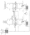
以下、本発明の作業機械の第4の実施の形態を図面を用いて説明する。図5は本発明の作業機械の第4の実施の形態を構成する油圧駆動装置の要部構成を示す概略図である。図5において、図1乃至図4に示す符号と同符号のものは同一部分であるので、その詳細な説明は省略する。 Hereinafter, a fourth embodiment of the work machine of the present invention will be described with reference to the drawings. FIG. 5 is a schematic view showing a configuration of a main part of a hydraulic drive device constituting a fourth embodiment of the working machine of the present invention. 5, the same reference numerals as those shown in FIGS. 1 to 4 denote the same parts, and a detailed description thereof will be omitted.
図5に示す本発明の作業機械の第4の実施の形態は、大略第2の実施の形態と同様の機器で構成されるが、以下の構成が異なる。
本実施の形態においては、表示装置48を備えた点が異なる。表示装置48は通信線を介して上位制御装置33に接続されていて、信号受信部48aと、表示部48bとを備えている。
The fourth embodiment of the work machine according to the present invention shown in FIG. 5 is configured by substantially the same equipment as the second embodiment, but differs in the following configuration.
The present embodiment is different in that a
次に、本実施の形態における、ポンプ制御装置が故障した場合の油圧アクチュエータを駆動させる動作について説明する。なお、ポンプ制御装置が故障していない場合の停止時及びブームシリンダ1の駆動方法、及びポンプ制御装置が故障した場合のブームシリンダ1の駆動方法については、第2の実施の形態と同様なので省略する。
まず、第1ポンプ制御装置18が故障して停止したときに、ブームシリンダ1を伸展動作させる場合について説明する。
Next, an operation of driving the hydraulic actuator when the pump control device fails in the present embodiment will be described. Note that the method for driving the
First, a case where the
上位制御装置33の故障判定部33bは、第1及び第2ポンプ制御装置18,19の稼働もしくは故障状態を判定する。故障状態の判定方法は、例えば、第1ポンプ制御装置18から通信線を介した稼働状態信号が、故障判定部33bに送られてきている場合は、故障判定部33bは正常な稼動状態と判定する。一方、一定時間、信号が送られてこない場合は、故障判定部33bは第1ポンプ制御装置18が故障状態と判定し、故障した第1ポンプ制御装置18のIDを故障ポンプ制御装置IDとして設定する。ここでIDは例えばポンプ制御装置の固有の製造番号等である。
The
上位制御装置33の信号送信部33cは、故障ポンプ制御装置IDと吐出流量制御信号を第1及び第2ポンプ制御装置18,19と表示装置48に通信線を介して送信する。第1及び第2ポンプ制御装置18,19と表示装置48の信号受信部18a,19a,48aは、故障ポンプ制御装置IDと吐出流量制御信号をそれぞれ受信する。表示装置48の表示部48bは、受信した故障ポンプ制御装置IDを画面に表示する。表示部48bは、ディスプレイやLCDなどの表示器であり、故障ポンプ制御装置IDをオペレータが認識できるものであれば良い。
The signal transmission unit 33c of the
ところで、第2の実施の形態においては、いずれかのポンプ制御装置が故障した場合に、オペレータもしくはメンテナンス実施作業者では、故障したポンプ制御装置の特定は困難であった。このため、別途、故障ポンプ制御装置の特定作業と、故障ポンプ制御装置の交換作業など、メンテナンスに時間がかかるという問題があった。 By the way, in the second embodiment, when any one of the pump control devices breaks down, it is difficult for the operator or the maintenance worker to identify the faulty pump control device. For this reason, there is a problem that it takes time for maintenance such as a specific operation of the failed pump control device and a replacement operation of the failed pump control device.
本実施の形態では、表示装置48を設けたので、いずれかのポンプ制御装置が故障して停止しても、故障したポンプ制御装置を特定することが容易となり、ポンプ制御装置の交換などのメンテナンスを早急に実施することができる。
In the present embodiment, since the
したがって、ポンプ制御装置が故障しても、早急にメンテナンスを実施し、正常なポンプ制御装置に交換することで、油圧ショベルの動作をすぐに正常に復帰することができる。このことにより、油圧ショベルの作業量の低下時間を抑制できる稼働率の高い油圧ショベルを提供できる。 Therefore, even if the pump control device breaks down, the operation of the hydraulic shovel can be returned to normal immediately by performing maintenance immediately and replacing it with a normal pump control device. This makes it possible to provide a hydraulic shovel with a high operating rate that can suppress the reduction time of the work amount of the hydraulic shovel.
また、以上の実施の形態では、ブームシリンダ1とアームシリンダ3を駆動させる油圧回路を中心に述べているが、この技術思想は旋回油圧モータ7とバケットシリンダ5の閉回路および開回路にも適用可能である。例えば、ブーム,アーム、バケット、旋回を駆動する4つの閉回路を備えた開閉ポンプ直接制御回路に本発明を適用して、4台のポンプ制御装置を備えても有効である。
In the above embodiment, the hydraulic circuit for driving the
一方、本発明と異なり、例えば、ブームシリンダ1とアームシリンダ3の回路に対して一のポンプ制御装置、バケットシリンダ5と旋回油圧モータ7の回路に対して他のポンプ制御装置を配置し、4つの開回路もしくは開閉回路に対して、2つのポンプ制御装置を備えることも考えられる。しかし、いずれかのポンプ制御装置が故障してしまうと、同時に駆動できるアクチュエータが2つのみとなってしまう。
On the other hand, unlike the present invention, for example, one pump control device is arranged for the circuit of the
4つの閉回路を備えた開閉ポンプ直接制御回路に4台のポンプ制御装置を備える本発明の構成であれば、1つのポンプ制御装置が故障しても3つのアクチュエータが同時に駆動できるので、油圧ショベルの稼働率を向上させることができる。 According to the configuration of the present invention in which the open / close pump direct control circuit having four closed circuits is provided with four pump controllers, three actuators can be driven simultaneously even if one pump controller fails, so that the hydraulic excavator can be used. Operating rate can be improved.
なお、本発明は、上述の各実施の形態に限定されるものではなく、その要旨を逸脱しない範囲内の様々な変形例が含まれる。例えば、上述した実施の形態では、本発明を油圧ショベルに適用した場合を例に挙げて説明したが、本発明は油圧ショベル以外の建設機械にも適用可能である。例えば、油圧式クレーン等、作業装置で複数の油圧アクチュエータを閉回路によって駆動する油圧装置を備えた作業機械の全般に本発明は適用可能である。 The present invention is not limited to the above-described embodiments, and includes various modifications without departing from the gist of the invention. For example, in the above-described embodiment, a case has been described in which the present invention is applied to a hydraulic shovel, but the present invention is also applicable to construction machines other than the hydraulic shovel. For example, the present invention is applicable to all types of work machines including a hydraulic device such as a hydraulic crane that includes a hydraulic device that drives a plurality of hydraulic actuators with a closed circuit using a work device.
1:ブームシリンダ、1a:ブームヘッド、1b:ブームロッド、2:ブーム、3:アームシリンダ、3a:アームヘッド、3b:アームロッド、4:アーム、5:バケットシリンダ、6:バケット、7:旋回油圧モータ、9:エンジン、10:動力伝達装置、11:第1片傾転ポンプ、12:第2片傾転ポンプ、11a,12a:レギュレータ(開回路ポンプ用調整器)、14〜17:切換弁、18:第1ポンプ制御装置、19:第2ポンプ制御装置、18a,19a:信号受信部、18b,19b:流量制御部、20〜31:流路、32:タンク、33:上位制御装置、33a:圧油制御部、33b:故障判定部、33c:信号送信部、34a,34b:操作レバー、35:第1両傾転ポンプ、36:第2両傾転ポンプ、35a,36a:レギュレータ(閉回路ポンプ用調整器)、37〜41,43:切換弁、42,44:流路(合流流路)、45a,b:チェック弁、46a,b:フラッシング弁、47:予備ポンプ制御装置、47a:信号受信部、47b:制御切換部、47c:流量制御部、48:表示装置、48a:信号受信部、48b:表示部、50:制御信号線、51:制御信号線、52:制御信号線、53:制御信号線、100:油圧ショベル、101:キャブ、102:上部旋回体、104:フロント作業機。 1: Boom cylinder, 1a: Boom head, 1b: Boom rod, 2: Boom, 3: Arm cylinder, 3a: Arm head, 3b: Arm rod, 4: Arm, 5: Bucket cylinder, 6: Bucket, 7: Swivel Hydraulic motor, 9: engine, 10: power transmission device, 11: first one-side tilt pump, 12: second one-side tilt pump, 11a, 12a: regulator (regulator for open circuit pump), 14-17: switching Valve, 18: first pump controller, 19: second pump controller, 18a, 19a: signal receiver, 18b, 19b: flow controller, 20 to 31: flow path, 32: tank, 33: upper controller , 33a: pressure oil control unit, 33b: failure determination unit, 33c: signal transmission unit, 34a, 34b: operation lever, 35: first double tilt pump, 36: second double tilt pump, 35a, 36a Regulators (regulators for closed circuit pumps), 37-41, 43: switching valves, 42, 44: channels (merging channels), 45a, b: check valves, 46a, b: flushing valves, 47: preliminary pump control Apparatus, 47a: signal receiving unit, 47b: control switching unit, 47c: flow control unit, 48: display device, 48a: signal receiving unit, 48b: display unit, 50: control signal line, 51: control signal line, 52: Control signal line, 53: control signal line, 100: hydraulic excavator, 101: cab, 102: upper swing body, 104: front work machine.
Claims (2)
前記操作レバーの操作量に基づいて前記複数の油圧ポンプから前記複数の油圧アクチュエータへの流路を前記流路切換弁により切り換えると共に、前記複数の油圧ポンプの吐出流量制御信号を算出する圧油制御部と、前記圧油制御部で算出した吐出流量制御信号を送信する信号送信部を備えた上位制御装置と、
前記複数の油圧ポンプそれぞれに対応して設けられ、前記複数の調整器を制御する複数のポンプ制御装置と、
前記上位制御装置によって制御される予備ポンプ制御装置とを備え、
前記複数のポンプ制御装置が、前記上位制御装置からの吐出流量制御信号を受信する信号受信部と、前記吐出流量制御信号に基づき前記複数のポンプの吐出流量を制御する指令信号を生成し、前記複数の調整器へ前記指令信号を出力する流量制御部とを有し、
前記上位制御装置は、前記複数のポンプ制御装置のうちいずれが故障しているか否かを判定する故障判定部を更に備え、
前記圧油制御部は、前記故障判定部が故障したと判断した一のポンプ制御装置と前記一のポンプ制御装置に接続された一のポンプを選択し、
前記信号送信部は、前記圧油制御部で選択された一のポンプの選択信号を前記予備ポンプ制御装置へ送信し、
前記予備ポンプ制御装置は、前記上位制御装置からの前記選択信号と前記吐出流量制御信号を受信する信号受信部と、前記選択信号と前記吐出流量制御信号に基づき駆動すべきポンプを選択する制御切換部と、前記吐出流量制御信号を基に前記ポンプの吐出流量を制御する指令信号をそれぞれ生成し、前記調整器へ前記指令信号を出力する流路制御部を備えた
ことを特徴とする作業機械。 A plurality of hydraulic pumps, a plurality of hydraulic actuators, and a plurality of hydraulic pumps, which are provided in flow paths connected to respective discharge sides of the plurality of hydraulic pumps, selectively connect the plurality of hydraulic pumps with the plurality of hydraulic actuators. In a working machine equipped with a flow path switching valve that switches to, a plurality of regulators that respectively adjust the discharge flow rates of the plurality of hydraulic pumps, and an operation lever that is operated by an operator,
Hydraulic oil control for switching a flow path from the plurality of hydraulic pumps to the plurality of hydraulic actuators by the flow path switching valve based on an operation amount of the operation lever and calculating a discharge flow control signal of the plurality of hydraulic pumps Unit, a higher-level control device including a signal transmission unit that transmits a discharge flow rate control signal calculated by the pressure oil control unit,
A plurality of pump control devices provided corresponding to each of the plurality of hydraulic pumps and controlling the plurality of regulators ,
A backup pump control device controlled by the host control device ,
The plurality of pump control devices, a signal receiving unit that receives a discharge flow rate control signal from the higher-level control device, and generates a command signal that controls the discharge flow rate of the plurality of pumps based on the discharge flow rate control signal, have a flow control unit for outputting the command signal to the plurality of regulators,
The higher-level control device further includes a failure determination unit that determines whether any of the plurality of pump control devices has failed,
The pressure oil control unit selects one pump control device and one pump connected to the one pump control device that the failure determination unit has determined to have failed,
The signal transmission unit transmits a selection signal of one pump selected by the pressure oil control unit to the backup pump control device,
A signal receiving unit that receives the selection signal and the discharge flow rate control signal from the higher-level control device; and a control switch that selects a pump to be driven based on the selection signal and the discharge flow rate control signal. A working machine , comprising: a flow control unit that generates a command signal for controlling a discharge flow rate of the pump based on the discharge flow control signal and outputs the command signal to the regulator. .
前記複数の油圧ポンプがそれぞれ両傾転ポンプであり、
前記複数の両傾転ポンプと前記複数の油圧アクチュエータとがそれぞれ流路で閉回路状に接続されると共に、前記流路のいずれか片側の流路に片傾転ポンプが接続された合流流路が形成されており、
前記複数の調整器が前記複数の両傾転ポンプの吐出流量をそれぞれ調整する両傾転ポンプ用調整器であり、
前記片傾転ポンプの吐出流量をそれぞれ調整する片傾転ポンプ用調整器を更に備え、
前記上位制御装置に設けられる前記圧油制御部が、前記複数の両傾転ポンプ及び前記複数の片傾転ポンプの吐出流量制御信号を算出し、
前記複数のポンプ制御装置が、前記複数の両傾転ポンプ用調整器及び前記複数の片傾転用調整器を制御し、前記流量制御部が、前記上位制御装置からの前記吐出流量制御信号に基づき、前記複数の両傾転ポンプ及び前記複数の片傾転ポンプの吐出流量を制御する指令信号を生成し、前記複数の両傾転ポンプ用調整器及び前記複数の片傾転ポンプ用調整器へ前記指令信号を出力する
ことを特徴とする作業機械。 The work machine according to claim 1,
Each of the plurality of hydraulic pumps is a double tilt pump,
A merging flow path in which the plurality of double tilt pumps and the plurality of hydraulic actuators are respectively connected in a closed path in a flow path, and a single tilt pump is connected to one of the flow paths. Is formed,
The plurality of regulators are regulators for a double tilt pump that respectively adjust the discharge flow rates of the multiple double tilt pumps,
Further comprising a one-sided pump adjuster for adjusting the discharge flow rate of the one-sided pump,
The pressure oil control unit provided in the higher-level control device calculates a discharge flow control signal of the plurality of double displacement pumps and the plurality of single displacement pumps,
The plurality of pump control devices controls the plurality of double tilt pump regulators and the plurality of single tilt regulators, and the flow rate control unit is based on the discharge flow rate control signal from the higher-level control device. Generating a command signal for controlling a discharge flow rate of the plurality of double tilt pumps and the plurality of single tilt pumps, to the plurality of double tilt pump regulators and the plurality of single tilt pump regulators; A work machine that outputs the command signal.
Priority Applications (1)
| Application Number | Priority Date | Filing Date | Title |
|---|---|---|---|
| JP2015252359A JP6636795B2 (en) | 2015-12-24 | 2015-12-24 | Work machine |
Applications Claiming Priority (1)
| Application Number | Priority Date | Filing Date | Title |
|---|---|---|---|
| JP2015252359A JP6636795B2 (en) | 2015-12-24 | 2015-12-24 | Work machine |
Publications (3)
| Publication Number | Publication Date |
|---|---|
| JP2017115994A JP2017115994A (en) | 2017-06-29 |
| JP2017115994A5 JP2017115994A5 (en) | 2018-12-06 |
| JP6636795B2 true JP6636795B2 (en) | 2020-01-29 |
Family
ID=59231602
Family Applications (1)
| Application Number | Title | Priority Date | Filing Date |
|---|---|---|---|
| JP2015252359A Active JP6636795B2 (en) | 2015-12-24 | 2015-12-24 | Work machine |
Country Status (1)
| Country | Link |
|---|---|
| JP (1) | JP6636795B2 (en) |
Families Citing this family (3)
| Publication number | Priority date | Publication date | Assignee | Title |
|---|---|---|---|---|
| JP2019049335A (en) * | 2017-09-12 | 2019-03-28 | 日立建機株式会社 | Construction machine |
| KR102453675B1 (en) * | 2020-11-04 | 2022-10-12 | 김영복 | Intergrated power module system for slag skimmer having spare power psck, and processing method thereof |
| FR3121945A1 (en) * | 2021-04-15 | 2022-10-21 | Charier | Works machine |
Family Cites Families (7)
| Publication number | Priority date | Publication date | Assignee | Title |
|---|---|---|---|---|
| JP4002696B2 (en) * | 1999-03-19 | 2007-11-07 | 株式会社トキメック | Hydraulic control system |
| JP2003148412A (en) * | 2001-11-08 | 2003-05-21 | Tokimec Inc | Hydraulic control system |
| CN101410632B (en) * | 2006-03-30 | 2013-02-13 | 油研工业株式会社 | Hydraulic supply device and method for controlling hydraulic actuator device using the same |
| KR101742322B1 (en) * | 2010-12-24 | 2017-06-01 | 두산인프라코어 주식회사 | Hydraulic system of construction machinery comprising emergency controller for electro-hydraulic pump |
| JP5778058B2 (en) * | 2012-03-09 | 2015-09-16 | 住友建機株式会社 | Construction machine control device and control method thereof |
| JP5961580B2 (en) * | 2013-04-11 | 2016-08-02 | 日立建機株式会社 | Drive device for work machine |
| JP6298716B2 (en) * | 2014-05-30 | 2018-03-20 | 日立建機株式会社 | Work machine |
-
2015
- 2015-12-24 JP JP2015252359A patent/JP6636795B2/en active Active
Also Published As
| Publication number | Publication date |
|---|---|
| JP2017115994A (en) | 2017-06-29 |
Similar Documents
| Publication | Publication Date | Title |
|---|---|---|
| CN101311020B (en) | Walking device for pedrail type heavy equipment | |
| US10107311B2 (en) | Hydraulic drive system for construction machine | |
| EP2977620B1 (en) | Hydraulic drive device of construction machine | |
| US10829908B2 (en) | Construction machine | |
| US10253479B2 (en) | Hydraulic system for work machine | |
| WO2011099214A1 (en) | Hydraulic excavator attachment control device | |
| CN107949706B (en) | Working machine | |
| WO2014091685A1 (en) | Hydraulic circuit for construction machine | |
| JP2007192344A (en) | Hydraulic control device of working machine | |
| JP6636795B2 (en) | Work machine | |
| CN109563695B (en) | Control valve for excavator and excavator | |
| JP6474702B2 (en) | Drive device for work machine | |
| JP6581444B2 (en) | Work machine | |
| CN110352303B (en) | Drive device for construction machine | |
| CN113396288B (en) | Engineering machinery | |
| US10072396B2 (en) | Working machine control system | |
| US10208457B2 (en) | Working machine control system | |
| KR20080051212A (en) | Hydraulic system for small-sized excavator to improve bucket speed | |
| KR102487257B1 (en) | Construction machinery | |
| JP5934669B2 (en) | Hydraulic drive unit for construction machinery | |
| JP2007192347A (en) | Hydraulic control device of working machine | |
| JPH09324446A (en) | Hydraulic drive device for construction vehicle | |
| KR20140110856A (en) | Hydraulic system for construction machine | |
| WO2019069612A1 (en) | Work vehicle | |
| JPH10299027A (en) | Hydraulic drive unit for construction machine |
Legal Events
| Date | Code | Title | Description |
|---|---|---|---|
| A521 | Written amendment |
Free format text: JAPANESE INTERMEDIATE CODE: A523 Effective date: 20181022 |
|
| A621 | Written request for application examination |
Free format text: JAPANESE INTERMEDIATE CODE: A621 Effective date: 20181022 |
|
| A131 | Notification of reasons for refusal |
Free format text: JAPANESE INTERMEDIATE CODE: A131 Effective date: 20190723 |
|
| A977 | Report on retrieval |
Free format text: JAPANESE INTERMEDIATE CODE: A971007 Effective date: 20190731 |
|
| A521 | Written amendment |
Free format text: JAPANESE INTERMEDIATE CODE: A523 Effective date: 20190920 |
|
| TRDD | Decision of grant or rejection written | ||
| A01 | Written decision to grant a patent or to grant a registration (utility model) |
Free format text: JAPANESE INTERMEDIATE CODE: A01 Effective date: 20191217 |
|
| A61 | First payment of annual fees (during grant procedure) |
Free format text: JAPANESE INTERMEDIATE CODE: A61 Effective date: 20191219 |
|
| R150 | Certificate of patent or registration of utility model |
Ref document number: 6636795 Country of ref document: JP Free format text: JAPANESE INTERMEDIATE CODE: R150 |