JP6634045B2 - Control device, control system - Google Patents
Control device, control system Download PDFInfo
- Publication number
- JP6634045B2 JP6634045B2 JP2017055071A JP2017055071A JP6634045B2 JP 6634045 B2 JP6634045 B2 JP 6634045B2 JP 2017055071 A JP2017055071 A JP 2017055071A JP 2017055071 A JP2017055071 A JP 2017055071A JP 6634045 B2 JP6634045 B2 JP 6634045B2
- Authority
- JP
- Japan
- Prior art keywords
- converter
- voltage
- load current
- range
- current
- Prior art date
- Legal status (The legal status is an assumption and is not a legal conclusion. Google has not performed a legal analysis and makes no representation as to the accuracy of the status listed.)
- Active
Links
- 238000006243 chemical reaction Methods 0.000 claims description 15
- 238000000034 method Methods 0.000 description 30
- 230000007423 decrease Effects 0.000 description 14
- 238000010586 diagram Methods 0.000 description 12
- 239000004065 semiconductor Substances 0.000 description 8
- 230000000694 effects Effects 0.000 description 6
- 239000003990 capacitor Substances 0.000 description 3
- 230000010363 phase shift Effects 0.000 description 3
- HBBGRARXTFLTSG-UHFFFAOYSA-N Lithium ion Chemical compound [Li+] HBBGRARXTFLTSG-UHFFFAOYSA-N 0.000 description 2
- 230000010485 coping Effects 0.000 description 2
- 230000003111 delayed effect Effects 0.000 description 2
- 229910001416 lithium ion Inorganic materials 0.000 description 2
- 230000001172 regenerating effect Effects 0.000 description 2
- 238000002485 combustion reaction Methods 0.000 description 1
- 238000009499 grossing Methods 0.000 description 1
- 230000004048 modification Effects 0.000 description 1
- 238000012986 modification Methods 0.000 description 1
- 238000010248 power generation Methods 0.000 description 1
- 230000001131 transforming effect Effects 0.000 description 1
Images


Description
電力変換システムに適用される制御装置、並びに電力変換システム及び制御装置を備える制御システムに関する。 The present invention relates to a control device applied to a power conversion system, and a control system including the power conversion system and the control device.
特許文献1には、エンジンの回転により発電するオルタネータと、蓄電装置からの入力電圧を変圧するDC/DCコンバータとを備える電力変換システムが開示されている。DC/DCコンバータは、入力電圧を変圧することで、出力電圧を生成し、給電対象に給電する。
ところで、共通の給電対象に給電する2つのDC/DCコンバータを備える電力変換システムが考えられる。このような電力変換システムにおいて、入力電圧又は出力電圧の変動に対応できるように、2つのDC/DCコンバータに対して広い入力電圧範囲又は出力電圧範囲に対応できる特性を均等に備えさせることが考えられる。しかし、2つのDC/DCコンバータに対して広い入力電圧範囲又は出力電圧範囲に対応できる特性を備えさせておくと、電力変換システムの効率が犠牲となる場合がある。 By the way, a power conversion system including two DC / DC converters for supplying power to a common power supply target is conceivable. In such a power conversion system, it is conceivable to equip two DC / DC converters with characteristics capable of coping with a wide input voltage range or output voltage range so as to be able to cope with fluctuations in input voltage or output voltage. Can be However, if the two DC / DC converters are provided with characteristics that can support a wide input voltage range or output voltage range, the efficiency of the power conversion system may be sacrificed.
本発明は上記課題を鑑みたものであり、システム全体での効率を犠牲にすることなく、入力電圧又は出力電圧の変動に対応することができる制御装置、及び制御装置を備える制御システムを提供することを目的とする。 The present invention has been made in view of the above problems, and provides a control device capable of coping with a change in an input voltage or an output voltage without sacrificing efficiency of the entire system, and a control system including the control device. The purpose is to:
上記課題を解決するために本発明に係る制御装置は、蓄電装置からの入力電圧を降圧して出力する第1DC/DCコンバータ及び第2DC/DCコンバータと、を備え、前記第1DC/DCコンバータ及び第2DC/DCコンバータから共通の給電対象に出力電圧を供給する電力変換システムに適用される。制御装置は、入力電圧又は出力電圧を電圧パラメータとして取得する電圧取得部と、前記給電対象に供給する負荷電流を取得する電流取得部と、前記電圧パラメータ及び前記負荷電流に基づいて、前記第1DC/DCコンバータ及び前記第2DC/DCコンバータの前記負荷電流に対する分担量を設定する分担設定部と、前記分担量に基づいて、前記第1DC/DCコンバータ及び前記第2DC/DCコンバータの動作を制御する動作制御部と、を備える。 In order to solve the above problem, a control device according to the present invention includes a first DC / DC converter and a second DC / DC converter that step down an input voltage from a power storage device and output the reduced voltage. The present invention is applied to a power conversion system that supplies an output voltage from a second DC / DC converter to a common power supply target. The control device is a voltage acquisition unit that acquires an input voltage or an output voltage as a voltage parameter, a current acquisition unit that acquires a load current supplied to the power supply target, and the first DC based on the voltage parameter and the load current. And a sharing setting unit that sets the sharing amount of the DC / DC converter and the second DC / DC converter with respect to the load current, and controls the operations of the first DC / DC converter and the second DC / DC converter based on the sharing amount. An operation control unit.
DC/DCコンバータの効率は、入力電圧又は出力電圧と、負荷電流とに応じて変化する。そこで、上記構成では、入力電圧又は出力電圧である電圧パラメータと負荷電流とに基づいて、第1DC/DCコンバータと第2DC/DCコンバータとの負荷電流に対する分担量を設定する。そして、設定された分担量に基づいて、第1DC/DCコンバータと第2DC/DCコンバータとの動作を制御することとした。この場合、各DC/DCコンバータの効率を考慮して負荷電流の分担量が設定されることで、電力変換システム全体での効率を犠牲にすることなく、入力電圧又は出力電圧の変動に対応することができる。 The efficiency of a DC / DC converter varies depending on the input or output voltage and the load current. Therefore, in the above configuration, the sharing amount of the first DC / DC converter and the second DC / DC converter with respect to the load current is set based on the voltage parameter that is the input voltage or the output voltage and the load current. Then, the operations of the first DC / DC converter and the second DC / DC converter are controlled based on the set sharing amount. In this case, by setting the share amount of the load current in consideration of the efficiency of each DC / DC converter, it is possible to cope with the fluctuation of the input voltage or the output voltage without sacrificing the efficiency of the entire power conversion system. be able to.
第2の発明では、前記第1DC/DCコンバータは、所定の前記電圧パラメータの範囲である第1範囲において、前記第2DC/DCコンバータよりも効率が高い。また、前記第2DC/DCコンバータは、前記第1範囲と異なる第2範囲において、前記第1DC/DCコンバータよりも効率が高い。そして、前記分担設定部は、前記電圧パラメータが前記第1範囲に含まれる場合に、前記第1DC/DCコンバータの前記分担量を、前記第2DC/DCコンバータの前記分担量よりも多く設定し、前記電圧パラメータが前記第2範囲に含まれる場合に、前記第2DC/DCコンバータの前記分担量を、前記第1DC/DCコンバータの前記分担量よりも多く設定する。 In the second aspect, the first DC / DC converter has higher efficiency than the second DC / DC converter in a first range that is a range of the predetermined voltage parameter. Further, the second DC / DC converter has a higher efficiency than the first DC / DC converter in a second range different from the first range. Then, the sharing setting unit sets the sharing amount of the first DC / DC converter to be larger than the sharing amount of the second DC / DC converter when the voltage parameter is included in the first range, When the voltage parameter is included in the second range, the shared amount of the second DC / DC converter is set to be larger than the shared amount of the first DC / DC converter.
上記構成により、変動後の電圧パラメータに応じて、第1,第2DC/DCコンバータのうち効率が高い方のDC/DCコンバータの分担量が、効率が低い方のDC/DCコンバータの分担量よりも多くなる。その結果、システム全体での効率の低下が抑制される。 According to the above configuration, in accordance with the voltage parameter after the change, the share of the DC / DC converter having the higher efficiency of the first and second DC / DC converters is larger than the share of the DC / DC converter having the lower efficiency. Also increase. As a result, a decrease in efficiency of the entire system is suppressed.
第3の発明では、前記電圧パラメータが前記第2範囲から前記第1範囲へ変化する際の前記第2DC/DCコンバータの効率の変化が、前記第1DC/DCコンバータの効率の変化よりも小さい。 In the third invention, a change in the efficiency of the second DC / DC converter when the voltage parameter changes from the second range to the first range is smaller than a change in the efficiency of the first DC / DC converter.
上記構成により、電圧パラメータが第1範囲に含まれる場合において、第2DC/DCコンバータを第1DC/DCコンバータに対して補助的に動作させる場合でも、第2DC/DCコンバータの効率が大きく低下しない。その結果、制御システム全体での効率の低下を抑制することができる。 According to the above configuration, when the voltage parameter is included in the first range, the efficiency of the second DC / DC converter does not significantly decrease even when the second DC / DC converter is operated auxiliary to the first DC / DC converter. As a result, a decrease in efficiency of the entire control system can be suppressed.
第4の発明では、前記分担設定部は、前記電圧パラメータが前記第2範囲に含まれる場合に、前記第1DC/DCコンバータを動作させない。上記構成により、効率が低い第2範囲では、第1DC/DCを動作させないことで、システム全体での効率の低下を抑制することができる。 In a fourth aspect, the sharing setting unit does not operate the first DC / DC converter when the voltage parameter is included in the second range. According to the above configuration, in the second range where the efficiency is low, the first DC / DC is not operated, so that a decrease in the efficiency of the entire system can be suppressed.
第5の発明では、前記第1DC/DCコンバータは、所定の負荷閾値よりも小さい負荷電流を出力する場合に、前記第2DC/DCコンバータよりも効率が低く、前記分担設定部は、前記電圧パラメータが前記第1範囲に含まれ、かつ前記負荷電流が前記負荷閾値よりも小さい場合は、前記第1DC/DCコンバータを動作させない。 In the fifth invention, when the first DC / DC converter outputs a load current smaller than a predetermined load threshold, the efficiency is lower than that of the second DC / DC converter. Is included in the first range and the load current is smaller than the load threshold, the first DC / DC converter is not operated.
第1DC/DCコンバータの効率が第2DC/DCコンバータの効率よりも低くなる負荷電流範囲では、第1DC/DCコンバータを動作させる場合に第1DC/DCコンバータで発生する損失が、第2DC/DCコンバータを動作させる場合に第2DC/DCコンバータで発生する損失よりも大きくなる。そのため、上記構成では、第1範囲であっても、第1DC/DCコンバータの効率が低くなる負荷電流範囲では、第1DC/DCコンバータを動作させないこととした。その結果、システム全体での効率の低下を抑制することができる。 In a load current range in which the efficiency of the first DC / DC converter is lower than the efficiency of the second DC / DC converter, the loss generated in the first DC / DC converter when operating the first DC / DC converter is reduced by the second DC / DC converter. Becomes larger than the loss that occurs in the second DC / DC converter when is operated. Therefore, in the above configuration, even in the first range, the first DC / DC converter is not operated in the load current range where the efficiency of the first DC / DC converter is low. As a result, a decrease in efficiency of the entire system can be suppressed.
第6の発明では、前記負荷電流が前記第1DC/DCコンバータの定格電流よりも小さい上限値未満であるか否かを判定する上限判定部を備え、前記分担設定部は、前記上限判定部により前記負荷電流が前記上限値より小さいと判定された場合に、前記第2DC/DCコンバータを動作させず、前記負荷電流が前記上限値以上と判定された場合に、前記第1DC/DCコンバータ及び前記第2DC/DCコンバータのそれぞれの前記分担量を設定して前記第1DC/DCコンバータ及び前記第2DC/DCコンバータを動作させる。 In a sixth aspect, an upper limit determining unit that determines whether the load current is less than an upper limit value smaller than a rated current of the first DC / DC converter is provided. When it is determined that the load current is smaller than the upper limit, the second DC / DC converter is not operated, and when it is determined that the load current is equal to or more than the upper limit, the first DC / DC converter and the The first DC / DC converter and the second DC / DC converter are operated by setting the respective share amounts of the second DC / DC converter.
第2DC/DCコンバータの動作が停止している状態から、第2DC/DCコンバータを起動して負荷電流を供給させる場合、第2DC/DCコンバータから負荷電流の供給が開始されるまでに時間を要する。そのため、給電対象に供給すべき負荷電流が急増する状況下、第1DC/DCコンバータの分担量が第1DC/DCコンバータの定格電流を超えた後に第2DC/DCコンバータを動作させ始めると、第2DC/DCコンバータからの電流の出力が遅れ、給電対象に実際に供給される負荷電流が供給すべき負荷電流よりも小さくなってしまうおそれがある。この点、上記構成では、第1DC/DCコンバータの定格電流よりも小さい値である上限値が定められている。そして、負荷電流が上限値以上となる場合に、第1,第2DC/DCコンバータのそれぞれを動作させることとした。この場合、第1DC/DCコンバータの定格電流未満の負荷電流を供給する状態から、第1,第2DC/DCコンバータを共に動作させることで、その後に負荷電流が増加する場合でも、第2DC/DCコンバータによる負荷電流の供給が遅れるのを防止することができる。 When starting the second DC / DC converter to supply the load current from the state where the operation of the second DC / DC converter is stopped, it takes time until the supply of the load current from the second DC / DC converter is started. . Therefore, when the load of the first DC / DC converter exceeds the rated current of the first DC / DC converter under a situation in which the load current to be supplied to the power supply target suddenly increases, the second DC / DC converter is started to operate. The output of the current from the / DC converter is delayed, and there is a possibility that the load current actually supplied to the power supply target becomes smaller than the load current to be supplied. In this regard, in the above configuration, the upper limit value that is smaller than the rated current of the first DC / DC converter is determined. When the load current is equal to or more than the upper limit, each of the first and second DC / DC converters is operated. In this case, by operating both the first and second DC / DC converters from a state in which a load current less than the rated current of the first DC / DC converter is supplied, even if the load current subsequently increases, the second DC / DC converter Delay of supply of load current by the converter can be prevented.
第7の発明では、前記分担設定部は、前記第1DC/DCコンバータ及び前記第2DC/DCコンバータの前記分担量をそれぞれの定格電流を超えないよう設定する。 In the seventh invention, the sharing setting unit sets the sharing amounts of the first DC / DC converter and the second DC / DC converter so as not to exceed respective rated currents.
上記構成により、各DC/DCコンバータの分担量がそれぞれの定格電流を超えない範囲に設定される。そのため、各DC/DCコンバータを適正な出力電流で動作させることができる。 According to the above configuration, the sharing amount of each DC / DC converter is set within a range that does not exceed the respective rated current. Therefore, each DC / DC converter can be operated with an appropriate output current.
本発明に係る前記制御装置と、前記電力変換システムと、を備える制御システムとしても用いることができる。 The present invention can also be used as a control system including the control device according to the present invention and the power conversion system.
(第1実施形態)
以下、本発明を具体化した第1実施形態を図面に基づいて説明する。図1は、第1実施形態に係る制御システム100の構成図である。制御システム100は、車両に搭載されている。また、この実施形態において、制御システム100が搭載される車両は、走行動力源として、内燃機関であるエンジンと、走行用モータとを備えるハイブリット車両である。
(1st Embodiment)
Hereinafter, a first embodiment of the present invention will be described with reference to the drawings. FIG. 1 is a configuration diagram of a
制御システム100は、蓄電装置に相当する第1蓄電池50と、インバータ51と、第1DC/DCコンバータ20と、第2DC/DCコンバータ30と、を備えている。以下では、第1DC/DCコンバータ20を第1DDC20と記載し、第2DC/DCコンバータ30を第2DDC30と記載する。本実施形態では、第1蓄電池50と、インバータ51と、第1DDC20と、第2DDC30とが電力変換システム90を構成している。
The
制御システム100には、給電対象としてのモータ11と、機器群60と、第2蓄電池55とが接続されている。そして、制御システム100は、第1蓄電池50により供給される電力に基づいて、モータ11と,機器群60と、第2蓄電池55とに給電する。
The
第1蓄電池50は、制御システム100における主たる電源として機能する。本実施形態では、第1蓄電池50は、リチウムイオン蓄電池である。具体的には、第1蓄電池50は、複数のリチウムイオン蓄電池のセルを組み合わせた組電池であり、例えば、200V〜400Vの第1端子電圧Vb1を生じさせる。
The first storage battery 50 functions as a main power supply in the
インバータ51は、第1蓄電池50から供給される電力を変換して、モータ11に給電する。インバータ51の入力側は、第1蓄電池50のプラス側端子と繋がる第1高圧ラインHL1、及び第1蓄電池50のマイナス側端子と繋がる第2高圧ラインHL2に接続されている。また、平滑コンデンサ52が、第1高圧ラインHL1と第2高圧ラインHL2との間においてインバータ51に並列接続されている。そして、インバータ51の出力側は、モータ11に接続されている。
The
モータ11は、インバータ51によって変換された交流電圧により駆動する。モータ11は、車両の走行用モータである。モータ11は、車両の走行中において車両の運動エネルギを利用して回生発電する機能を有している。また、インバータ51は、交流電流を直流電流に整流する整流機能を備えている。インバータ51は、車両の制動時には、回生発電によってモータ11から出力された交流電流を直流電流に整流する。整流された直流電流が各高圧ラインHL1,HL2を通じて第1蓄電池50に供給されることにより、第1蓄電池50が充電される。
The
第1DDC20は、インダクタとコンデンサとにより共振を生じさせる電流共振型のコンバータである。本実施形態では、第1DDC20は、低圧側の第1回路と高圧側の第2回路とがトランスを介して接続された絶縁型の降圧コンバータである。
The
第1DDC20の第1回路は、複数の半導体スイッチを備える。第1DDC20は、各半導体スイッチのオン・オフを切り替えることで、第1端子電圧Vb1に対する降圧動作を実施する。第1DDC20の第1入力端子Ti1は、第1高圧ラインHL1と繋がる第3高圧ラインHL3に接続されている。また、第2入力端子Ti2は、第2高圧ラインHL2に繋がる第4高圧ラインHL4に接続されている。また、第1出力端子To1は、サブ配線SLに接続されている。
The first circuit of the
第1回路には、この第1回路に流れる第1電流IH1を検出する第1電流センサ21が設けられている。第1電流センサ21により検出された第1電流IH1と、第1DDC20のトランスの巻数比とに基づいて、第1DDC20の第2回路から出力される出力電流を推定することができる。以下では、第1DDC20の出力電流を第1出力電流Iout1と記載する。
The first circuit is provided with a first
第2DDC30は、複数の半導体スイッチのオン期間のタイミングを制御する位相シフト型のコンバータである。本実施形態では、第2DDC30は、低圧側の第3回路と高圧側の第4回路とがトランスを介して接続された絶縁型の降圧コンバータである。
The
第2DDC30の第3回路は、複数の半導体スイッチを備える。第2DDC30は、各半導体スイッチのオン・オフを切り替えることで、第1端子電圧Vb1に対する降圧動作を実施する。第2DDC30の第3入力端子Ti3は、第1高圧ラインHL1と繋がる第5高圧ラインHL5に接続されている。また、第4入力端子Ti4は、第2高圧ラインHL2に繋がる第6高圧ラインHL6に接続されている。第2DDC30の第2出力端子To2は、サブ配線SLに接続されている。
The third circuit of the
第3回路には、この第3回路に流れる第2電流IH2を検出する第2電流センサ31が設けられている。第2電流センサ31により検出された第2電流IH2と、第2DDC30のトランスの巻数比とに基づいて、第2DDC30の第4回路から出力される出力電流を推定することができる。以下では、第2DDC30の出力電流を第2出力電流Iout2と記載する。
The third circuit is provided with a second
本実施形態では、第1DDC20の定格電流は、第2DDC30の定格電流よりも大きい。例えば、第1DDC20の定格電流は、150[A]であり、第2DDC30の定格電流は、30[A]である。また、第1DDC20の定格電流は、制御システム100に対して要求される負荷電流ILの最大値よりも大きい値となっている。
In the present embodiment, the rated current of the
サブ配線SLには、このサブ配線SLを通じて給電される機器群60と第2蓄電池55とが接続されている。機器群60の正極側端子は、サブ配線SLに接続されている。また、機器群60の負極側端子は、グランドに接続されている。機器群60は、例えば、オーディオ機器、ナビゲーション装置、パワースライドドア、パワーバックドア、メータ等である。また、第2蓄電池55のプラス側端子はサブ配線SLに接続され、マイナス側端子はグランドに接続されている。そのため、サブ配線SLには、第1,第2DDC20,30の出力電圧Vout及び第2蓄電池55の端子電圧である第2端子電圧Vb2の少なくともいずれかが印加される。
The sub-wiring SL is connected to the
本実施形態において、第2蓄電池55の蓄電容量は、第1蓄電池50の蓄電容量よりも小さい。また、第2蓄電池55の第2端子電圧Vb2は、第1蓄電池50の第1端子電圧Vb1よりも小さい。例えば、第2蓄電池55の満充電時の端子電圧は、12Vである。
In the present embodiment, the storage capacity of the
制御システム100は、制御装置10を備えている。制御装置10は、ユーザのアクセル操作量に応じてモータ11の駆動に必要な指令トルクを算出する。制御装置10は、モータ11のトルクを指令トルクに制御すべく、インバータ51を制御する。
The
また、制御装置10は、第1,第2DDC20,30の半導体スイッチを駆動させる。制御装置10は、第1,第2DDC20,30の出力電圧Vout1,Vout2を第1,第2出力電圧指令値V1*,V2*に制御すべく、各半導体スイッチの1スイッチング周期に対するオン期間の比であるデューティ比を制御する。例えば、制御装置10は、第1,第2DDC20,30に共通となる上位電圧指令値VP*を設定し、この上位電圧指令値VP*から各出力電圧指令値V1*,V2*を設定する。制御装置10によるデューティ比の制御により、第1,第2DDC20,30の出力電圧Vout1,Vout2が制御され、サブ配線SLに供給される。
The
なお、本実施形態では、制御装置10を一つの装置として説明するが、これに限定されない。例えば、インバータ51を制御する制御装置と、第1,第2DDC20,30の半導体スイッチを駆動させる制御装置とを別々に備える構成としてもよい。
In the present embodiment, the
制御システム100は、電圧センサ53を備えている。電圧センサ53は、第1蓄電池50のプラス側端子とマイナス側端子とに並列接続されており、第1端子電圧Vb1を検出する。
The
次に、第1,第2DDC20,30の第1端子電圧Vb1に対する効率特性を、図2を用いて説明する。図2では、横軸を第1端子電圧Vb1とし、縦軸を効率η(電力変換効率)とするグラフである。横軸において、第1端子電圧Vb1を、第1電圧範囲RV1と、第2電圧範囲RV2と、第3電圧範囲RV3とに区別している。第1電圧範囲RV1に含まれる電圧値は第1境界値よりも小さく、第2電圧範囲RV2に含まれる電圧値は第1境界値よりも大きい。また、第2電圧範囲RV2に含まれる電圧値は第2境界値よりも小さく、第3電圧範囲RV3に含まれる電圧値は第2境界値よりも大きい。第1境界値は第2境界値よりも小さい値である。また、第1電圧範囲RV1の最小値が、第1端子電圧Vb1の下限値となっている。そして、第3電圧範囲RV3の最大値が、第1端子電圧Vb1の上限値となっている。
Next, the efficiency characteristics of the first and
第2電圧範囲RV2が第1範囲に相当し、第1電圧範囲RV1及び第3電圧範囲RV3が第2範囲に相当する。本実施形態では、効率ηを、第1,第2DDC20,30の入力電力に対する出力電力の割合として定めている。
The second voltage range RV2 corresponds to a first range, and the first voltage range RV1 and the third voltage range RV3 correspond to a second range. In the present embodiment, the efficiency η is defined as the ratio of the output power to the input power of the first and
第1DDC20の第1効率η1は、第2電圧範囲RV2において、第2DDC30の第2効率η2よりも高い値となる。図2では、第2電圧範囲RV2において、第1効率η1は第1効率閾値Thη1以上の値であるのに対して、第2効率η2は第1効率閾値Thη1より低い値となる。一方、第1,第3電圧範囲RV1,RV3において、第1効率η1は第2効率η2よりも低い値となる。
The first efficiency η1 of the
また、第1端子電圧Vb1が第2電圧範囲RV2から第1電圧範囲RV1又は第3電圧範囲RV3へ変化する際の第1端子電圧Vb1の変化に対する第2効率η2の変化は、第1効率η1の変化よりも小さい。各電圧範囲RV1〜RV3において、第1DDC20の第1効率η1は、第1効率閾値Thη1以上の値から第2効率閾値Thη2以下の値に変動する。一方、各電圧範囲RV1〜RV3において、第2効率η2は、第2効率閾値Thη2以上でかつ第1効率閾値Thη1未満の値に変動する。第2効率閾値Thη2は第1効率閾値Thη1よりも小さな値である。
Further, when the first terminal voltage Vb1 changes from the second voltage range RV2 to the first voltage range RV1 or the third voltage range RV3, the change in the second efficiency η2 with respect to the change in the first terminal voltage Vb1 is the first efficiency η1 Less than the change. In each of the voltage ranges RV1 to RV3, the first efficiency η1 of the
ところで、制御システム100では、入力電圧である第1端子電圧Vb1に変動が生じる場合がある。例えば、第1蓄電池50からインバータ51を通じてモータ11に供給される電流が多くなることで、第1端子電圧Vb1が低下する。ここで、第1,第2DDC20,30に対して広い入力電圧範囲に対応できる特性を均等に備えさせておくと、制御システム100全体での効率が犠牲となる場合がある。また、制御システム100では、機器群60の要求する負荷電流ILが変動する場合がある。そして、第1,第2DDC20,30の各効率η1,η2は、負荷電流ILの変動によっても変化する。
By the way, in the
そこで、制御装置10は、第1端子電圧Vb1を電圧パラメータとし、この電圧パラメータと、負荷電流ILとに応じて、第1,第2DDC20,30の負荷電流ILの分担量(Iout1,Iout2)を設定することとした。図3は、各電圧範囲RV1〜RV3での第1,第2DDC20,30の動作を説明する図である。本実施形態では、第1DDC20の第1効率η1が第2DDC30の第2効率η2よりも高い第2電圧範囲RV2において、第1DDC20を優先的に動作させる。即ち、第1DDC20の第1出力電流Iout1が第2DDC30の第2出力電流Iout2よりも多くなるよう設定される。一方、第2DDC30の第2効率η2が第1DDC20の第1効率η1よりも高い第1電圧範囲RV1及び第3電圧範囲RV3では、第2DDC30を優先的に動作させる。即ち、第2出力電流Iout2が第1出力電流Iout1よりも多くなるよう設定される。更に、第2電圧範囲RV2においても、第1DDC20における負荷電流ILに対する特性に応じて、第2DDC30を補助的に動作させることで、分担量を変更している。
Therefore, the
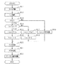
次に、第1端子電圧Vb1と負荷電流ILとに応じた分担量の設定処理を説明する。図4は、第1,第2DDC20,30の分担量の設定処理を説明するフローチャートである。図4のフローチャートで示す処理は、制御装置10により所定の制御周期で繰り返し実施される。図4において、ステップS13〜S18,S21が分担設定部に相当する。
Next, a process of setting the sharing amount according to the first terminal voltage Vb1 and the load current IL will be described. FIG. 4 is a flowchart illustrating a setting process of the sharing amounts of the first and
ステップS11では、第1端子電圧Vb1を取得する。第1端子電圧Vb1は、電圧センサ53による実測値として取得される。ステップS11が電圧取得部に相当する。
In step S11, the first terminal voltage Vb1 is obtained. The first terminal voltage Vb1 is obtained as an actually measured value by the
ステップS12では、負荷電流ILを取得する。本実施形態では、第1電流IH1と第2電流IH2とに基づいて、第1,第2DDC20,30の出力電流Iout1,Iout2の合計を負荷電流ILとして推定する。ステップS12が電流取得部に相当する。
In step S12, the load current IL is obtained. In the present embodiment, the sum of the output currents Iout1 and Iout2 of the first and
ステップS13では、ステップS11で取得した第1端子電圧Vb1が第2電圧範囲RV2に含まれるか否かを判定する。ステップS13において、第1端子電圧Vb1が第2電圧範囲RV2に含まれると判定すると、ステップS14に進む。ステップS14〜S18では、負荷電流ILに占める第1出力電流Iout1が第2出力電流Iout2よりも多くなるように、分担量を設定する。 In step S13, it is determined whether the first terminal voltage Vb1 acquired in step S11 is included in the second voltage range RV2. If it is determined in step S13 that the first terminal voltage Vb1 is included in the second voltage range RV2, the process proceeds to step S14. In steps S14 to S18, the sharing amount is set such that the first output current Iout1 in the load current IL becomes larger than the second output current Iout2.
図5は、第2電圧範囲RV2における負荷電流ILと効率η1,η2との関係を説明する図である。図5では、横軸を負荷電流ILとし、縦軸を効率ηとして示している。また、第1DDC20の定格電流と比べて低負荷電流範囲となる境界を第1負荷閾値ThL1として示している。以下では、第1DDC20の定格電流を第1定格電流Ir1とし、第2DDC30の定格電流を第2定格電流Ir2とする。
FIG. 5 is a diagram illustrating the relationship between the load current IL and the efficiencies η1 and η2 in the second voltage range RV2. In FIG. 5, the horizontal axis represents the load current IL, and the vertical axis represents the efficiency η. Further, a boundary where the load current range is lower than the rated current of the
第2電圧範囲RV2においても、負荷電流ILに応じて第1DDC20の第1効率η1が変化する。第1DDC20の第1定格電流Ir1は、第1負荷閾値ThL1よりも大きな値であるため、負荷電流ILが減少することで第1定格電流Ir1から離れるに従い、第1効率η1が低くなっている。これに対して、第2DDC30の第2定格電流Ir2は第1定格電流Ir1と比べて第1負荷閾値ThL1に近い値であり、第1負荷閾値ThL1以下であっても、負荷電流ILの減少に対する第2効率η2の低下は、第1効率η1の低下よりも少ない。そのため、第1負荷閾値ThL1以下となる低負荷電流範囲では、第1DDC20の第1効率η1は、第2DDC30の第2効率η2よりも低くなっている。
Also in the second voltage range RV2, the first efficiency η1 of the
図6は、負荷電流ILに応じた分担量を説明する図である。負荷電流ILが第1負荷閾値ThL1よりも小さい場合は、制御装置10は、第2出力電流Iout2のみで負荷電流ILを供給するよう第1,第2DDC20,30の分担量を設定する。一方、負荷電流ILが第1負荷閾値ThL1以上である場合は、第1出力電流Iout1のみで負荷電流ILを供給するよう第1,第2DDC20,30の分担量を設定する。
FIG. 6 is a diagram illustrating the sharing amount according to the load current IL. When the load current IL is smaller than the first load threshold ThL1, the
図4の説明に戻り、ステップS14では、負荷電流ILを第1負荷閾値ThL1と比較する。ステップS14において、負荷電流ILが第1負荷閾値ThL1より小さいと判定すると、ステップS15に進む。ステップS15では、ステップS12で取得した負荷電流ILを第2DDC30の分担量である第2出力電流Iout2として設定する。
Returning to the description of FIG. 4, in step S14, the load current IL is compared with a first load threshold ThL1. If it is determined in step S14 that the load current IL is smaller than the first load threshold ThL1, the process proceeds to step S15. In step S15, the load current IL acquired in step S12 is set as the second output current Iout2, which is the shared amount of the
ステップS16では、第1DDC20から機器群60へ電流が供給されないように、第1DDC20の分担量である第1出力電流Iout1を0に設定する。すなわち、負荷電流ILが第1負荷閾値ThL1より小さい場合は、第2DDC30のみで負荷電流ILを供給させ、第1DDC20に負荷電流ILを供給させない。
In step S16, the first output current Iout1, which is the shared amount of the
一方、ステップS14において負荷電流ILが第1負荷閾値ThL1以上であると判定すると、ステップS17に進む。ステップS17では、ステップS12で取得した負荷電流ILを、第1出力電流Iout1として設定する。 On the other hand, if it is determined in step S14 that the load current IL is equal to or greater than the first load threshold ThL1, the process proceeds to step S17. In step S17, the load current IL obtained in step S12 is set as the first output current Iout1.
ステップS18では、第2DDC30から機器群60へ負荷電流ILが供給されないよう第2出力電流Iout2を0に設定する。すなわち、負荷電流ILが第1負荷閾値ThL1以上である場合は、第1DDC20のみで負荷電流ILを供給させ、第2DDC30に負荷電流ILを供給させない。
In step S18, the second output current Iout2 is set to 0 so that the load current IL is not supplied from the
ステップS13において、第1端子電圧Vb1が第2電圧範囲RV2に含まれないと判定すると、ステップS19に進む。この場合、第1端子電圧Vb1は、各電圧範囲RV1,RV3に含まれるため、第2DDC30を優先的に動作させるほうが、制御システム100の効率が高くなる。そのため、ステップS21では、第2出力電流Iout2のみで負荷電流ILを供給するよう分担量を設定する。具体的には、第1出力電流Iout1を0に設定し、第2出力電流Iout2を負荷電流ILに設定する。
If it is determined in step S13 that the first terminal voltage Vb1 is not included in the second voltage range RV2, the process proceeds to step S19. In this case, since the first terminal voltage Vb1 is included in each of the voltage ranges RV1 and RV3, the operation of the
ステップS20では、ステップS16、S17又はS21で設定した第1出力電流Iout1に応じて、第1出力電圧指令値V1*を設定する。例えば、各ステップS16,S17で設定した第1出力電流Iout1と、第1電流IH1に応じて推定した第1出力電流Iout1との偏差ΔI1を算出する。そして、算出した偏差ΔI1に応じて、第1出力電圧指令値V1*を設定する。具体的には、偏差ΔI1を入力値とし、上位電圧指令値VP*の補正値を出力値とする比例積分制御を実施する。そして算出した補正値により上位電圧指令値VP*補正し、補正後の上位電圧指令値VP*を第1出力電圧指令値V1*として設定する。 In step S20, the first output voltage command value V1 * is set according to the first output current Iout1 set in step S16, S17 or S21. For example, a deviation ΔI1 between the first output current Iout1 set in each of steps S16 and S17 and the first output current Iout1 estimated according to the first current IH1 is calculated. Then, the first output voltage command value V1 * is set according to the calculated deviation ΔI1. Specifically, proportional integral control is performed in which the deviation ΔI1 is used as an input value, and the correction value of the upper voltage command value VP * is used as an output value. Then, the upper voltage command value VP * is corrected by the calculated correction value, and the corrected higher voltage command value VP * is set as the first output voltage command value V1 *.
ステップS21では、ステップS15、S18又はS21で設定した第2出力電流Iout2に応じて第2出力電圧指令値V2*を設定する。例えば、各ステップS15,S18で設定した第2出力電流Iout2と、第2電流IH2に応じて推定した第2出力電流Iout2との偏差ΔI2を算出する。そして、算出した偏差ΔI2に応じて、第2出力電圧指令値V2*を設定する。具体的には、偏差ΔI2を入力値とし、上位電圧指令値VP*の補正値を出力値とする比例積分制御を実施する。そして算出した補正値により上位電圧指令値VP*を補正し、補正後の上位電圧指令値VP*を第2出力電圧指令値V2*として設定する。 In step S21, the second output voltage command value V2 * is set according to the second output current Iout2 set in step S15, S18 or S21. For example, a deviation ΔI2 between the second output current Iout2 set in each of steps S15 and S18 and the second output current Iout2 estimated according to the second current IH2 is calculated. Then, the second output voltage command value V2 * is set according to the calculated deviation ΔI2. Specifically, proportional integral control is performed using the deviation ΔI2 as an input value and the correction value of the upper voltage command value VP * as an output value. Then, the upper voltage command value VP * is corrected by the calculated correction value, and the corrected higher voltage command value VP * is set as the second output voltage command value V2 *.
ステップS22では、ステップS20,S21で設定した各出力電圧指令値V1*,V2*に応じて、第1,第2DDC20,30を動作させる。ステップS22が動作制御部に相当する。
In step S22, the first and
以上説明した本実施形態によれば、以下の効果を奏する。 According to the above-described embodiment, the following effects can be obtained.
・制御装置10は、第1端子電圧Vb1及び負荷電流ILに基づいて、第1,第2DDC20,30における負荷電流ILの分担量を設定する。そして、設定した分担量に基づいて、第1,第2DDC20,30を動作させることとした。この場合、第1,第2DDC20,30の各効率η1,η2を考慮して、各出力電流Iout1,Iout2が設定されることで、制御システム100全体での効率を犠牲にすることなく第1端子電圧Vb1の変動に対応することができる。
The
・制御装置10は、第1端子電圧Vb1が第2電圧範囲RV2に含まれる場合に、第1出力電流Iout1を第2出力電流Iout2よりも多くする。また、制御装置10は、第1端子電圧Vb1が第1電圧範囲RV1又は第3電圧範囲RV3に含まれる場合に、第2出力電流Iout2を第1出力電流Iout1よりも多くする。上記構成により、第1端子電圧Vb1が変動する場合でも、効率が高い方のDDC20,30の出力電流Iout1,Iout2が、効率が低い方のDDC30の出力電流Iout1,Iout2よりも多くなる。そのため、制御システム100全体での効率を高めることができる。
The
・第1端子電圧Vb1が第2電圧範囲RV2から第1電圧範囲RV1又は第3電圧範囲RV3へ変化する際の第2DDC30の第2効率η2の変化は、第1DDC20の第1効率η1の変化よりも小さい。上記構成により、第1端子電圧Vb1が第2電圧範囲RV2に含まれる場合において、制御装置10が第2DDC30を第1DDC20に対して補助的に動作させる場合でも、第2効率η2が大きく低下しない。その結果、制御システム100全体での効率の低下を抑制することができる。
The change in the second efficiency η2 of the
・制御装置10は、第1端子電圧Vb1が第2電圧範囲RV2に含まれない場合に、第1DDC20を動作させない。上記構成により、効率が低い範囲では、第1DDC20を動作させないことで、制御システム100全体での効率が低下するのを抑制することができる。
The
・制御装置10は、第1端子電圧Vb1が第2電圧範囲RV2に含まれ、負荷電流ILが低負荷電流範囲に含まれる場合は、第2出力電流Iout2のみで負荷電流ILを供給させるように、各出力電流Iout1,Iout2を設定する。そのため、低負荷電流範囲においては、第1DDC20を動作させず、制御システム100全体での効率の低下を抑制することができる。
When the first terminal voltage Vb1 is included in the second voltage range RV2 and the load current IL is included in the low load current range, the
(第2実施形態)
この第2実施形態では、第1実施形態と異なる構成を中心に説明する。
(2nd Embodiment)
In the second embodiment, a description will be given mainly of a configuration different from the first embodiment.
図7は、第2実施形態に係る負荷電流ILと、効率ηとの関係を説明する図である。第2電圧範囲RV2において、第1DDC20を優先的に動作させる場合でも、負荷電流ILが第1DDC20の第1定格電流Ir1よりも大きな値となる場合がある。図7では、第2負荷閾値ThL2は、第1定格電流Ir1を示す値である。また、第3負荷閾値ThL3は、機器群60が要求する負荷電流ILの最大値であり、第2負荷閾値ThL2よりも大きな値である。図7に示すように、負荷電流ILが第2負荷閾値ThL2よりも大きくかつ第3負荷閾値ThL3以下の値では、第1DDC20のみで負荷電流ILを供給できない場合がある。
FIG. 7 is a diagram illustrating the relationship between the load current IL and the efficiency η according to the second embodiment. In the second voltage range RV2, even when the
図8は、第2実施形態に係る負荷電流ILの分担量を説明する図である。この第2実施形態では、第1,第2DDC20,30の定格電流は同じ値(例えば、75A)である。負荷電流ILが第2負荷閾値ThL2よりも小さい場合、制御装置10は第1DDC10のみで負荷電流ILを供給させる。また、負荷電流ILが第2負荷閾値ThL2以上となる場合、制御装置10は、第1DDC20を優先的に動作させつつ、第2DDC30を第1DDC20に対して補助的に動作させることで、負荷電流ILが不足することを防止している。
FIG. 8 is a diagram illustrating the sharing amount of the load current IL according to the second embodiment. In the second embodiment, the first and
図9は、第2実施形態に係る第1,第2DDC20,30の分担量の設定処理を説明するフローチャートである。図9のフローチャートで示す処理は、制御装置10により所定の制御周期で繰り返し実施される。
FIG. 9 is a flowchart illustrating a process of setting the sharing amounts of the first and
ステップS31では、負荷電流ILと第2負荷閾値ThL2とを比較する。ステップS31において、負荷電流ILが第2負荷閾値ThL2より小さいと判定すれば、ステップS32に進む。 In step S31, the load current IL is compared with the second load threshold ThL2. If it is determined in step S31 that the load current IL is smaller than the second load threshold ThL2, the process proceeds to step S32.
ステップS32では、ステップS12で取得した負荷電流ILを第1出力電流Iout1として設定する。ステップS33では、第2DDC20から機器群60へ負荷電流ILが供給されないよう第2出力電流Iout2を0に設定する。
In step S32, the load current IL obtained in step S12 is set as the first output current Iout1. In step S33, the second output current Iout2 is set to 0 so that the load current IL is not supplied from the
ステップS31において、負荷電流ILが第2負荷閾値ThL2以上であると判定すれば、ステップS34に進む。ステップS34では、第1出力電流Iout1を第1定格電流Ir1を超えない範囲で設定する。本実施形態では、第1定格電流Ir1を第1出力電流Iout1に設定する。 If it is determined in step S31 that the load current IL is equal to or greater than the second load threshold ThL2, the process proceeds to step S34. In step S34, the first output current Iout1 is set within a range not exceeding the first rated current Ir1. In the present embodiment, the first rated current Ir1 is set to the first output current Iout1.
ステップS35では、負荷電流ILからステップS34で設定した第1出力電流Iout1を引いた値を、第2出力電流Iout2として設定する。 In step S35, a value obtained by subtracting the first output current Iout1 set in step S34 from the load current IL is set as the second output current Iout2.
ステップS20では、ステップS32、S34及びS19で設定した第1出力電流Iout1に応じて、第1出力電圧指令値V1*を設定する。ステップS21では、ステップS33、S35及びS19で設定した第2出力電流Iout2に応じて、第2出力電圧指令値V2*を設定する。 In step S20, the first output voltage command value V1 * is set according to the first output current Iout1 set in steps S32, S34, and S19. In step S21, the second output voltage command value V2 * is set according to the second output current Iout2 set in steps S33, S35, and S19.
以上説明した本実施形態では、以下の効果を奏する。 The embodiment described above has the following effects.
・制御装置10は、負荷電流ILの分担量を第1,第2DDC20,30の定格電流Ir1,Ir2を超えないよう設定する。そのため、第1,第2DDC20,30を適正な出力電流Iout1,Iout2で動作させることができる。
The
(第3実施形態)
この第3実施形態では、第1実施形態と異なる構成を中心に説明する。
(Third embodiment)
In the third embodiment, a description will be given focusing on a configuration different from the first embodiment.
図10は、第3実施形態に係る負荷電流ILの分担量を説明する図である。この第3実施形態では、第1DDC20の定格電流は120Aであるのに対して、第2DDC30の定格電流は30Aであり、定格電流が異なる。また、負荷電流ILの最大値は、第1,第2DDC20,30のそれぞれの定格電流Ir1,Ir2よりも大きく、かつ第1,第2DDC20,30のそれぞれの定格電流Ir1,Ir2の和以下となっている。本実施形態では、負荷電流ILの最大値は、第1定格電流Ir1と第2定格電流Ir2との和(例えば、150A)となっている。
FIG. 10 is a diagram illustrating the sharing amount of the load current IL according to the third embodiment. In the third embodiment, the rated current of the
負荷電流ILが第1負荷閾値ThL1よりも小さい場合は、制御装置10は、第2DDC30のみで負荷電流ILを供給させる。一方、負荷電流ILが第1負荷閾値ThL1以上であり、かつ第3負荷閾値ThL3より小さい場合は、制御装置10は、第1DDC20のみで負荷電流ILを供給させる。そして、負荷電流ILが第3負荷閾値ThL3以上となる最大負荷範囲において、第1,第2DDC20,30を共に動作させる。
When the load current IL is smaller than the first load threshold ThL1, the
図11は、第3実施形態に係る第1,第2DDC20,30の分担量の設定処理を説明するフローチャートである。図11のフローチャートで示す処理は、制御装置10により所定の制御周期で繰り返し実施される。
FIG. 11 is a flowchart illustrating a process of setting the sharing amounts of the first and
ステップS14において、負荷電流ILが第1負荷閾値ThL1以上であれば、ステップS41に進み、負荷電流ILの最大値付近を示す第3負荷閾値ThL3と比較する。ステップS41において、負荷電流ILが第3負荷閾値ThL3より小さいと判定すると、ステップS17に進む。ステップS41が負荷判定部に相当する。 If the load current IL is equal to or greater than the first load threshold ThL1 in step S14, the process proceeds to step S41, where the load current IL is compared with a third load threshold ThL3 indicating the vicinity of the maximum value of the load current IL. If it is determined in step S41 that the load current IL is smaller than the third load threshold ThL3, the process proceeds to step S17. Step S41 corresponds to a load determination unit.
一方、ステップS41において、負荷電流ILが第3負荷閾値ThL3以上であると判定すると、ステップS42に進む。ステップS42では、第1出力電流Iout1を第1定格電流Ir1に設定する。ステップS43では、第2出力電流Iout2を第2定格電流Ir2に設定する。 On the other hand, if it is determined in step S41 that the load current IL is equal to or more than the third load threshold ThL3, the process proceeds to step S42. In step S42, the first output current Iout1 is set to the first rated current Ir1. In step S43, the second output current Iout2 is set to the second rated current Ir2.
ステップS20では、設定した第1出力電流Iout1に応じて第1出力電圧指令値V1*を設定する。ステップS21では、設定した第2出力電流Iout2に応じて第2出力電圧指令値V2*を設定する。そのため、機器群60には、第1定格電流Ir1と第2定格電流Ir2とを足し合わせた負荷電流が流れる。
In step S20, a first output voltage command value V1 * is set according to the set first output current Iout1. In step S21, the second output voltage command value V2 * is set according to the set second output current Iout2. Therefore, a load current obtained by adding the first rated current Ir1 and the second rated current Ir2 flows through the
以上説明した本実施形態によれば、以下の効果を奏する。 According to the above-described embodiment, the following effects can be obtained.
・制御装置10は、負荷電流ILの最大値付近では、第1,第2DDC20,30にそれぞれの定格電流Ir1,Ir2を供給させることとした。そのため、負荷電流ILの最大値よりも第1定格電流Ir1を小さくすることができるため、第1DDC20の出力容量の増加を抑制し、体格を小さくすることができる。そのため、制御システム100のコストを抑えることができる。
The
(第4実施形態)
この第4実施形態では、第1実施形態と異なる構成を中心に説明する。
(Fourth embodiment)
In the fourth embodiment, a description will be given mainly of a configuration different from the first embodiment.
第2DDC30の動作が停止している状態から、負荷電流ILを供給させる場合、負荷電流ILの供給が開始するまでに所定の時間を要する。そのため、第1DDC20の分担量が第1定格電流Ir1を超えた後に、第2DDC30を補助的に動作させると、負荷電流ILの増加に第2DDC30による第2出力電流Iout2の供給が遅れるおそれがある。そこで、制御装置10は、第1出力電流Iout1の負荷電流ILに対する割合が高い値とならないように上限値を設け、負荷電流ILが上限値以上となった場合に、第1,第2DDC20,30のそれぞれの分担量を設定する。
When the load current IL is supplied from the state where the operation of the
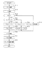
図12は、第4実施形態に係る第1,第2DDC20,30の分担量の設定処理を説明するフローチャートである。図12のフローチャートで示す処理は、制御装置10により所定の制御周期で繰り返し実施される。
FIG. 12 is a flowchart illustrating a process of setting the sharing amounts of the first and
ステップS14において、負荷電流ILが第1負荷閾値ThL1以上であると判定すると、ステップS51に進む。ステップS51では、負荷電流ILを上限閾値ULと比較する。上限閾値ULは、第1定格電流Ir1より小さな値を示す。割合値SRが上限閾値ULより小さい場合、ステップS17に進む。ステップS51が上限判定部に相当する。 If it is determined in step S14 that the load current IL is equal to or greater than the first load threshold ThL1, the process proceeds to step S51. In step S51, the load current IL is compared with an upper threshold UL. The upper threshold UL indicates a value smaller than the first rated current Ir1. If the ratio value SR is smaller than the upper threshold UL, the process proceeds to step S17. Step S51 corresponds to an upper limit determination unit.
ステップS17では、負荷電流ILを第1出力電流Iout1として設定する。そして、ステップS18では、第2出力電流Iout2を0に設定する。 In step S17, the load current IL is set as the first output current Iout1. Then, in step S18, the second output current Iout2 is set to 0.
一方、負荷電流ILが上限閾値ULより大きいと判定すると、ステップS53に進む。ステップS53,S54では、負荷電流ILの増加に応じて設定される第1DDC20の分担量が第1定格電流Ir1を超えないように、第2DDC30の分担量を設定する。例えば、ステップS53では、第1定格電流Ir1から電流補正値Ciを引いた値を第1出力電流Iout1として設定する。電流補正値Ciは、ステップS12で取得された負荷電流ILに応じて変化する値である。ステップS54では、負荷電流ILからステップS54で設定した第1出力電流Iout1を引いた値を、第2出力電流Iout2として設定する。
On the other hand, if it is determined that the load current IL is larger than the upper threshold UL, the process proceeds to step S53. In steps S53 and S54, the sharing amount of the
ステップS20では、設定した第1出力電流Iout1に応じて第1出力電圧指令値V1*を設定する。ステップS21では、設定した第2出力電流Iout2に応じて第2出力電圧指令値V2*を設定する。 In step S20, a first output voltage command value V1 * is set according to the set first output current Iout1. In step S21, the second output voltage command value V2 * is set according to the set second output current Iout2.
以上説明した本実施形態によれば、以下の効果を奏する。 According to the above-described embodiment, the following effects can be obtained.
・制御装置10は、負荷電流ILが第1定格電流Ir1より小さい値を示す上限閾値ULより小さいと判定すると、第1DDC20のみを動作させ、負荷電流ILが上限閾値UL以上であると判定すると、第1,第2DDC20,30のそれぞれを動作させることとした。そのため、負荷電流ILが第1定格電流Ir1よりも小さい状態で、第1,第2DDC20,30を共に動作させることで、急な負荷電流ILの増加に第2DDC30による第2出力電流Iout2の供給が遅れるのを防止することができる。
When the
(第4実施形態の変形例)
第1定格電流Ir1に占める第1出力電流Iout1の割合を算出し、ステップS51において、この割合が上限値を超える場合に、第1,第2DDC20,30を共に動作させるものであってもよい。
(Modification of Fourth Embodiment)
The ratio of the first output current Iout1 to the first rated current Ir1 may be calculated, and if the ratio exceeds the upper limit in step S51, the first and
(第5実施形態)
この第5実施形態では、第1実施形態と異なる構成を中心に説明する。
(Fifth embodiment)
In the fifth embodiment, a description will be given focusing on a configuration different from the first embodiment.
図4のステップS19において、第2DDC30を優先動作させる場合に、負荷電流ILに応じて、第1DDC20を第2DDC30に対して補助的に動作させる。
In step S19 of FIG. 4, when the
図13は、図4のステップS19で制御装置10が実施する処理を説明するフローチャートである。ステップS61では、負荷電流ILを第4負荷閾値ThL4と比較する。第4負荷閾値ThL4は、第2DDC20の第2定格電流Ir2を示す値である。
FIG. 13 is a flowchart illustrating a process performed by
ステップS61において、負荷電流ILが第4負荷閾値ThL4よりも小さい場合、第2DDC30のみで負荷電流ILを供給することができる。そのため、ステップS62では、負荷電流ILを第2出力電流Iout2として設定する。ステップS63では、第1DDC20から負荷電流ILを供給させないように第1出力電流Iout1を0に設定する。
In step S61, when the load current IL is smaller than the fourth load threshold ThL4, the load current IL can be supplied only by the
一方、ステップS61において、負荷電流ILが第4負荷閾値ThL4以上であれば、第2DDC30のみで負荷電流ILを供給することができなくなる。そのため、ステップS64では、第2定格電流Ir2を第2出力電流Iout2として設定する。
On the other hand, in step S61, if the load current IL is equal to or larger than the fourth load threshold ThL4, the load current IL cannot be supplied only by the
ステップS65では、負荷電流ILからステップS64で設定した第2出力電流Iout2を引いた値を、第1出力電流Iout1として設定する。 In step S65, a value obtained by subtracting the second output current Iout2 set in step S64 from the load current IL is set as the first output current Iout1.
ステップS66では、ステップS62又はS64で設定した第2出力電流Iout2に応じて、第2出力電圧指令値V2*を設定する。ステップS67では、ステップS63又はS65で設定した第1出力電流Iout1に応じて、第1出力電圧指令値V1*を設定する。 In step S66, the second output voltage command value V2 * is set according to the second output current Iout2 set in step S62 or S64. In step S67, the first output voltage command value V1 * is set according to the first output current Iout1 set in step S63 or S65.
以上説明した本実施形態によれば、以下の効果を奏する。 According to the above-described embodiment, the following effects can be obtained.
・制御装置10は、第1端子電圧Vb1が第2電圧範囲VR2以外となる場合においても、第2DDC30の第2出力電流Iout2が第2定格電流Ir2以上となることを防止する。そのため、第1,第2DDC20,30を適正に動作させることができる。
The
(第6実施形態)
この第6実施形態では、第1実施形態と異なる構成を中心に説明する。
(Sixth embodiment)
In the sixth embodiment, a description will be given focusing on a configuration different from the first embodiment.
この第6実施形態では、第1DDC20と第2DDC30とは、共に位相シフト型のコンバータとして構成されているが、トランスの巻数比が異なる。具体的には、第1端子電圧Vb1が第1,第2DDC20,30を高い効率η1,η2とする電圧範囲に含まれる場合に、適正な各出力電圧Vout1,Vout2となるよう第1,第2DDC20,30のトランスの巻数比が定められている。以下では、第1DDC20のトランスの巻数比をN1とし、第2DDC30のトランスの巻数比をN2とする。巻数比を、二次側のコイルの巻数に対する一次側のコイルの巻数の比により定めている。そして、第1DDC20の巻数比N1は、第2DDC30の巻数比N2よりも小さい値となっている。
In the sixth embodiment, the
第1DDC20は、第1端子電圧Vb1が第2電圧範囲RV2に含まれる場合に、適正な第1出力電圧Vout1となるようトランスの巻数比N1が定められている。また、第2DDC30は、第1端子電圧Vb1が第1電圧範囲RV1に含まれる場合に、適正な第2出力電圧Vout2となるようトランスの巻数比N2が定められている。
In the
上記構成の制御システム100においても、図4のステップS13で、第1端子電圧Vb1が第2電圧範囲RVに含まれると判定すると、第1DDC20を優先的に動作させるよう第1,第2DDC20,30の分担量を設定する(ステップS14〜S18)。また、ステップS13において、第1端子電圧Vb1が第2電圧範囲RVに含まれないと判定すると、第2DDC20を優先的に動作させるよう第1,第2DDC20,30の分担量を設定する(ステップS19)。
Also in the
(第7実施形態)
この第7実施形態では、第1実施形態と異なる構成を中心に説明する。
(Seventh embodiment)
In the seventh embodiment, a description will be given mainly of a configuration different from the first embodiment.
第1,第2DDC20,30の効率η1,η2は、各出力電圧Vout1,Vout2によっても変化する。図14は、出力電圧Voutと、効率ηとの関係を説明する図である。図14では、横軸を各出力電圧Vout1,Vout2とし、縦軸を効率ηとした場合のグラフである。横軸において、各出力電圧Vout1,Vout2を、第4電圧範囲RV4と、第5電圧範囲RV5と、第6電圧範囲RV6とに区別している。第4電圧範囲RV4に含まれる電圧値は第3境界値よりも小さく、第5電圧範囲RV5に含まれる電圧値は第3境界値よりも大きい。また、第5電圧範囲RV5に含まれる電圧値は第4境界値よりも小さく、第6電圧範囲RV6に含まれる電圧値は第4境界値よりも大きい。第3境界値は第4境界値よりも小さい値である。第4電圧範囲RV4の最小値は、第1,第2DDC20,30の各出力電圧Vout1,Vout2の下限値であり、第6電圧範囲RV6の最大値は、第1,第2DDC20,30の各出力電圧Vout1,Vout2の上限値である。
The efficiencies η1 and η2 of the first and
第1DDC20の第1効率η1は、第5電圧範囲RV5において、第2DDC30の第2効率η2よりも高い値となる。図14では、第5電圧範囲RV5において、第1効率η1は第3効率閾値Thη3より高い値であるのに対して、第2効率η2は第3効率閾値Thη3より低い値となる。一方、第4,第6電圧範囲RV4,RV6において、第1効率η1は第2効率η2よりも低い値となる。
The first efficiency η1 of the
また、各出力電圧Vout1,Vout2が第5電圧範囲RV5から第4電圧範囲RV4又は第6電圧範囲RV6へ変化する際の各出力電圧Vout1,Vout2の変化に対する第2効率η2の変化は、第1効率η1の変化よりも小さい。各電圧範囲RV4〜RV6において、第1DDC20の第1効率η1は、第3効率閾値Thη3以上の値から第4効率閾値Thη4以下の値に変動する。一方、各電圧範囲RV4〜RV6において、第2効率η2は、第4効率閾値Thη4以上でかつ第3効率閾値Thη3未満の値に変動する。第4効率閾値Thη4は第3効率閾値Thη3よりも小さな値である。
Further, when the output voltages Vout1 and Vout2 change from the fifth voltage range RV5 to the fourth voltage range RV4 or the sixth voltage range RV6, the change in the second efficiency η2 with respect to the change in the output voltages Vout1 and Vout2 is the first efficiency η2. It is smaller than the change in the efficiency η1. In each of the voltage ranges RV4 to RV6, the first efficiency η1 of the
図15は、第7実施形態に係る第1,第2DDC20,30の分担量の設定処理を説明するフローチャートである。図15のフローチャートで示す処理は、制御装置10により所定の制御周期で繰り返し実施される。
FIG. 15 is a flowchart illustrating a process of setting the sharing amounts of the first and
ステップS71では、第1DDC20に要求される第1出力電圧Vout1を取得する。例えば、現在の第1出力電圧指令値V1*に応じて、第1DDC20の第1出力電圧Vout1を推定する。なお、第2出力電圧Vout2と第1出力電圧Vout1とが同じ値である場合に、ステップS71では、第2出力電圧Vout2を取得するものであってもよい。
In step S71, the first output voltage Vout1 required for the
ステップS72では、ステップS71で取得した第1出力電圧Vout1が第5電圧範囲RV5に含まれるか否かを判定する。ステップS73において、第1出力電圧Vout1が第5電圧範囲RV5に含まれると判定すると、ステップS14に進む。そして、負荷電流ILに応じて、第1DDC20の分担量と、第2DDC30の分担量とを設定する(ステップS15〜S18)。
In step S72, it is determined whether the first output voltage Vout1 obtained in step S71 is included in the fifth voltage range RV5. If it is determined in step S73 that the first output voltage Vout1 is included in the fifth voltage range RV5, the process proceeds to step S14. Then, the sharing amount of the
ステップS72において、第1出力電圧Vout1が第5電圧範囲RV5に含まれないと判定すると、ステップS19に進む。ステップS19では、第2DDC30により負荷電流ILを供給させるよう分担量を設定する。
If it is determined in step S72 that the first output voltage Vout1 is not included in the fifth voltage range RV5, the process proceeds to step S19. In step S19, the sharing amount is set so that the
以上説明した本実施形態によれば、以下の効果を奏する。 According to the above-described embodiment, the following effects can be obtained.
・制御装置10は、第1出力電圧Vout1が変動する場合において、第1,第2DDC20,30の効率η1,η2を考慮して、負荷電流ILに対する分担量(Iout1,Iout2)を設定する。そのため、制御システム100全体での効率を犠牲にすることなく出力電圧Voutの変動に対応することができる。
When the first output voltage Vout1 fluctuates, the
(その他の実施形態)
・第1,第2DDC20,30の定格電流Ir1,Ir2が異なる場合に、第1定格電流Ir1により定めた定格電流範囲に基づいて、第1,第2DDC20,30の分担量を設定するものであってもよい。この場合、第1端子電圧Vb1が第2電圧範囲RV2に含まれており、かつ負荷電流ILが定格電流範囲に含まれていることを条件に、第1DDC20の分担量を、第2DDC30の分担量よりも多くする。一方、第1端子電圧Vb1が第2電圧範囲RV2に含まれておらず、又は負荷電流ILが定格電流範囲に含まれていない場合のいずれかが成立する場合に、第2DDC30の分担量を、第1DDC20の分担量よりも多くする。
(Other embodiments)
When the rated currents Ir1 and Ir2 of the first and
・第1DDC20をフライバック方式のコンバータにより構成し、第2DDC30を位相シフト方式のコンバータにより構成するものであってもよい。この場合においても、第1DDC20は第2電圧範囲RV2において第2DDC30よりも高い効率となる。
The
・蓄電装置は、直流電圧を供給する装置であればよく、蓄電池に限定されない。例えば、蓄電装置としてキャパシタが用いられてもよい。 The power storage device may be any device that supplies a DC voltage, and is not limited to a storage battery. For example, a capacitor may be used as the power storage device.
・第1,第2DDC20,30は、車両以外の装置に搭載されるものであってもよい。
The first and
・電流センサは、サブ配線SLに流れる負荷電流ILを直接検出するものであってもよい。 The current sensor may directly detect the load current IL flowing through the sub-wiring SL.
・制御システム100は、第2蓄電池55を備えていなくともよい。
The
10…制御装置、20…第1DC/DCコンバータ、30…第2DC/DCコンバータ、50…第1蓄電池、90…電力変換システム、100…制御システム、IL…負荷電流。 10: control device, 20: first DC / DC converter, 30: second DC / DC converter, 50: first storage battery, 90: power conversion system, 100: control system, IL: load current.
Claims (7)
前記入力電圧又は前記出力電圧を電圧パラメータとして取得する電圧取得部と、
前記給電対象に供給する負荷電流を取得する電流取得部と、
前記電圧パラメータ及び前記負荷電流に基づいて、前記第1DC/DCコンバータ及び前記第2DC/DCコンバータの前記負荷電流に対する分担量を設定する分担設定部と、
前記分担量に基づいて、前記第1DC/DCコンバータ及び前記第2DC/DCコンバータの動作を制御する動作制御部と、を備え、
前記第1DC/DCコンバータは、所定の前記電圧パラメータの範囲である第1範囲において、前記第2DC/DCコンバータよりも効率が高く、前記第2DC/DCコンバータは、前記第1範囲と異なる第2範囲において、前記第1DC/DCコンバータよりも効率が高く、
前記分担設定部は、前記電圧パラメータが前記第1範囲に含まれる場合に、前記第1DC/DCコンバータの前記分担量を、前記第2DC/DCコンバータの前記分担量よりも多く設定し、前記電圧パラメータが前記第2範囲に含まれる場合に、前記第2DC/DCコンバータの前記分担量を、前記第1DC/DCコンバータの前記分担量よりも多く設定し、
前記第1DC/DCコンバータは、所定の負荷閾値よりも小さい前記負荷電流を出力する場合に、前記第2DC/DCコンバータよりも効率が低く、
前記分担設定部は、前記電圧パラメータが前記第1範囲に含まれ、かつ前記負荷電流が前記負荷閾値よりも小さい場合は、前記第1DC/DCコンバータを動作させない制御装置。 A first DC / DC converter (20) and a second DC / DC converter (30) for stepping down an input voltage from the power storage device (50) are provided, and a common power supply target (1) is supplied from the first DC / DC converter and the second DC / DC converter. 55, 60) applied to a power conversion system (90) for supplying an output voltage to
A voltage acquisition unit that acquires the input voltage or the output voltage as a voltage parameter,
A current acquisition unit that acquires a load current to be supplied to the power supply target,
A sharing setting unit configured to set a sharing amount of the first DC / DC converter and the second DC / DC converter with respect to the load current based on the voltage parameter and the load current;
Based on the allocation amount, Bei give a, an operation control unit that controls the operation of the second 1 DC / DC converter and the second 2DC / DC converter,
The first DC / DC converter has a higher efficiency than the second DC / DC converter in a first range that is the range of the predetermined voltage parameter, and the second DC / DC converter has a second efficiency different from the first range. In the range, the efficiency is higher than the first DC / DC converter,
The sharing setting unit sets the sharing amount of the first DC / DC converter to be larger than the sharing amount of the second DC / DC converter when the voltage parameter is included in the first range. When the parameter is included in the second range, the shared amount of the second DC / DC converter is set to be larger than the shared amount of the first DC / DC converter,
The first DC / DC converter has a lower efficiency than the second DC / DC converter when outputting the load current smaller than a predetermined load threshold,
The control device that does not operate the first DC / DC converter when the voltage parameter is included in the first range and the load current is smaller than the load threshold .
前記分担設定部は、前記上限判定部により前記負荷電流が前記上限値未満であると判定された場合に、前記第2DC/DCコンバータを動作させず、前記負荷電流が前記上限値以上と判定された場合に、前記第1DC/DCコンバータ及び前記第2DC/DCコンバータのそれぞれの前記分担量を設定して前記第1DC/DCコンバータ及び前記第2DC/DCコンバータを動作させる請求項1に記載の制御装置。 An upper limit determining unit that determines whether the load current is less than an upper limit smaller than a rated current of the first DC / DC converter,
The sharing setting unit does not operate the second DC / DC converter when the upper limit determining unit determines that the load current is less than the upper limit, and determines that the load current is equal to or greater than the upper limit. 2. The control according to claim 1 , wherein when the first DC / DC converter and the second DC / DC converter are set, the shared amounts of the first DC / DC converter and the second DC / DC converter are set to operate the first DC / DC converter and the second DC / DC converter. 3. apparatus.
前記入力電圧又は前記出力電圧を電圧パラメータとして取得する電圧取得部と、A voltage acquisition unit that acquires the input voltage or the output voltage as a voltage parameter,
前記給電対象に供給する負荷電流を取得する電流取得部と、A current acquisition unit that acquires a load current to be supplied to the power supply target,
前記電圧パラメータ及び前記負荷電流に基づいて、前記第1DC/DCコンバータ及び前記第2DC/DCコンバータの前記負荷電流に対する分担量を設定する分担設定部と、A sharing setting unit configured to set a sharing amount of the first DC / DC converter and the second DC / DC converter with respect to the load current based on the voltage parameter and the load current;
前記分担量に基づいて、前記第1DC/DCコンバータ及び前記第2DC/DCコンバータの動作を制御する動作制御部と、を備え、An operation control unit that controls operations of the first DC / DC converter and the second DC / DC converter based on the shared amount,
前記第1DC/DCコンバータは、所定の前記電圧パラメータの範囲である第1範囲において、前記第2DC/DCコンバータよりも効率が高く、前記第2DC/DCコンバータは、前記第1範囲と異なる第2範囲において、前記第1DC/DCコンバータよりも効率が高く、The first DC / DC converter has a higher efficiency than the second DC / DC converter in a first range that is the range of the predetermined voltage parameter, and the second DC / DC converter has a second efficiency different from the first range. In the range, the efficiency is higher than the first DC / DC converter,
前記分担設定部は、前記電圧パラメータが前記第1範囲に含まれる場合に、前記第1DC/DCコンバータの前記分担量を、前記第2DC/DCコンバータの前記分担量よりも多く設定し、前記電圧パラメータが前記第2範囲に含まれる場合に、前記第2DC/DCコンバータの前記分担量を、前記第1DC/DCコンバータの前記分担量よりも多く設定し、The sharing setting unit sets the sharing amount of the first DC / DC converter to be larger than the sharing amount of the second DC / DC converter when the voltage parameter is included in the first range. When the parameter is included in the second range, the shared amount of the second DC / DC converter is set to be larger than the shared amount of the first DC / DC converter,
前記負荷電流が前記第1DC/DCコンバータの定格電流よりも小さい上限値未満であるか否かを判定する上限判定部を備え、An upper limit determining unit that determines whether the load current is less than an upper limit smaller than a rated current of the first DC / DC converter,
前記分担設定部は、前記上限判定部により前記負荷電流が前記上限値未満であると判定された場合に、前記第2DC/DCコンバータを動作させず、前記負荷電流が前記上限値以上と判定された場合に、前記第1DC/DCコンバータ及び前記第2DC/DCコンバータのそれぞれの前記分担量を設定して前記第1DC/DCコンバータ及び前記第2DC/DCコンバータを動作させる制御装置。The sharing setting unit does not operate the second DC / DC converter when the upper limit determining unit determines that the load current is less than the upper limit, and determines that the load current is equal to or greater than the upper limit. A control device that sets the shared amount of each of the first DC / DC converter and the second DC / DC converter to operate the first DC / DC converter and the second DC / DC converter.
前記電力変換システムと、を備える制御システム。 The control device according to any one of claims 1 to 6 ,
And a power conversion system.
Priority Applications (6)
| Application Number | Priority Date | Filing Date | Title |
|---|---|---|---|
| JP2017055071A JP6634045B2 (en) | 2017-03-21 | 2017-03-21 | Control device, control system |
| DE112018000424.4T DE112018000424T5 (en) | 2017-01-18 | 2018-01-15 | Energy conversion system control unit and control system |
| PCT/JP2018/000852 WO2018135442A1 (en) | 2017-01-18 | 2018-01-15 | Control device for power conversion system, and power conversion system |
| CN201880007355.XA CN110192336B (en) | 2017-01-18 | 2018-01-15 | Control device and control system for power conversion system |
| US16/504,178 US10848068B2 (en) | 2017-01-18 | 2019-07-05 | Power conversion system control device and control system |
| US16/854,408 US11201545B2 (en) | 2017-01-18 | 2020-04-21 | Power conversion system control device and control system |
Applications Claiming Priority (1)
| Application Number | Priority Date | Filing Date | Title |
|---|---|---|---|
| JP2017055071A JP6634045B2 (en) | 2017-03-21 | 2017-03-21 | Control device, control system |
Publications (3)
| Publication Number | Publication Date |
|---|---|
| JP2018157737A JP2018157737A (en) | 2018-10-04 |
| JP2018157737A5 JP2018157737A5 (en) | 2019-04-18 |
| JP6634045B2 true JP6634045B2 (en) | 2020-01-22 |
Family
ID=63716970
Family Applications (1)
| Application Number | Title | Priority Date | Filing Date |
|---|---|---|---|
| JP2017055071A Active JP6634045B2 (en) | 2017-01-18 | 2017-03-21 | Control device, control system |
Country Status (1)
| Country | Link |
|---|---|
| JP (1) | JP6634045B2 (en) |
Families Citing this family (2)
| Publication number | Priority date | Publication date | Assignee | Title |
|---|---|---|---|---|
| JP7332331B2 (en) * | 2019-05-10 | 2023-08-23 | トヨタ自動車株式会社 | power supply |
| JP7340975B2 (en) * | 2019-07-19 | 2023-09-08 | 新電元工業株式会社 | DC/DC converter system, operation instruction circuit, and DC/DC converter system control method |
Family Cites Families (5)
| Publication number | Priority date | Publication date | Assignee | Title |
|---|---|---|---|---|
| JPH09308231A (en) * | 1996-05-17 | 1997-11-28 | Toko Inc | Switching power supply |
| US8564989B2 (en) * | 2010-12-22 | 2013-10-22 | Intel Corporation | Cold swap load adaptive power supply |
| JP5634327B2 (en) * | 2011-05-24 | 2014-12-03 | 三菱電機株式会社 | DC / DC converter device |
| JP2016025748A (en) * | 2014-07-18 | 2016-02-08 | 株式会社東芝 | Power supply system and control unit |
| JP6409515B2 (en) * | 2014-11-12 | 2018-10-24 | 富士電機株式会社 | Insulated AC-DC converter |
-
2017
- 2017-03-21 JP JP2017055071A patent/JP6634045B2/en active Active
Also Published As
| Publication number | Publication date |
|---|---|
| JP2018157737A (en) | 2018-10-04 |
Similar Documents
| Publication | Publication Date | Title |
|---|---|---|
| US10848068B2 (en) | Power conversion system control device and control system | |
| JP5786325B2 (en) | Power conversion circuit system | |
| CA2753689C (en) | Battery charger using phase shift double forward converting circuit | |
| CN109314466B (en) | Parallel power supply device | |
| JP5958449B2 (en) | Power conversion system | |
| JP6292801B2 (en) | Power system | |
| US11594895B2 (en) | Power supply system | |
| KR101558794B1 (en) | Battery charger for an electric vehicle | |
| JP2015204639A (en) | Power conversion apparatus and control method thereof | |
| JP4321467B2 (en) | Power switching device | |
| JP2019004544A (en) | Control system | |
| JP6634045B2 (en) | Control device, control system | |
| JP6187180B2 (en) | Power conversion system | |
| JP5928518B2 (en) | Power conversion apparatus and control method thereof | |
| JP4319613B2 (en) | DC-DC converter device for vehicle | |
| KR20170086298A (en) | Charging control system for electric vehicle | |
| EP3782841A1 (en) | System of increasing temperature of battery for vehicle | |
| JP2012249348A (en) | Power supply control system | |
| JP6762173B2 (en) | Power converter | |
| JP6636595B1 (en) | Power converter | |
| KR102633710B1 (en) | High-efficiency charger and method of driving the same | |
| JP2021175209A (en) | Power system and power supply device | |
| KR20230112174A (en) | Fast charger for electric vehicles operable in high-efficiency and method of operating the same | |
| JP2022138710A (en) | DC-DC converter and vehicle | |
| JP2021175210A (en) | Power system and power supply device |
Legal Events
| Date | Code | Title | Description |
|---|---|---|---|
| A521 | Request for written amendment filed |
Free format text: JAPANESE INTERMEDIATE CODE: A523 Effective date: 20190307 |
|
| A621 | Written request for application examination |
Free format text: JAPANESE INTERMEDIATE CODE: A621 Effective date: 20190307 |
|
| TRDD | Decision of grant or rejection written | ||
| A01 | Written decision to grant a patent or to grant a registration (utility model) |
Free format text: JAPANESE INTERMEDIATE CODE: A01 Effective date: 20191119 |
|
| A61 | First payment of annual fees (during grant procedure) |
Free format text: JAPANESE INTERMEDIATE CODE: A61 Effective date: 20191213 |
|
| R150 | Certificate of patent or registration of utility model |
Ref document number: 6634045 Country of ref document: JP Free format text: JAPANESE INTERMEDIATE CODE: R150 |
|
| R250 | Receipt of annual fees |
Free format text: JAPANESE INTERMEDIATE CODE: R250 |
|
| R250 | Receipt of annual fees |
Free format text: JAPANESE INTERMEDIATE CODE: R250 |