JP6632204B2 - Driving device, robot device, and article manufacturing method - Google Patents
Driving device, robot device, and article manufacturing method Download PDFInfo
- Publication number
- JP6632204B2 JP6632204B2 JP2015050123A JP2015050123A JP6632204B2 JP 6632204 B2 JP6632204 B2 JP 6632204B2 JP 2015050123 A JP2015050123 A JP 2015050123A JP 2015050123 A JP2015050123 A JP 2015050123A JP 6632204 B2 JP6632204 B2 JP 6632204B2
- Authority
- JP
- Japan
- Prior art keywords
- torque
- unit
- drive
- housing
- joint
- Prior art date
- Legal status (The legal status is an assumption and is not a legal conclusion. Google has not performed a legal analysis and makes no representation as to the accuracy of the status listed.)
- Active
Links
Images


Classifications
-
- B—PERFORMING OPERATIONS; TRANSPORTING
- B25—HAND TOOLS; PORTABLE POWER-DRIVEN TOOLS; MANIPULATORS
- B25J—MANIPULATORS; CHAMBERS PROVIDED WITH MANIPULATION DEVICES
- B25J9/00—Programme-controlled manipulators
- B25J9/16—Programme controls
- B25J9/1628—Programme controls characterised by the control loop
- B25J9/1633—Programme controls characterised by the control loop compliant, force, torque control, e.g. combined with position control
-
- B—PERFORMING OPERATIONS; TRANSPORTING
- B25—HAND TOOLS; PORTABLE POWER-DRIVEN TOOLS; MANIPULATORS
- B25J—MANIPULATORS; CHAMBERS PROVIDED WITH MANIPULATION DEVICES
- B25J17/00—Joints
-
- B—PERFORMING OPERATIONS; TRANSPORTING
- B25—HAND TOOLS; PORTABLE POWER-DRIVEN TOOLS; MANIPULATORS
- B25J—MANIPULATORS; CHAMBERS PROVIDED WITH MANIPULATION DEVICES
- B25J13/00—Controls for manipulators
- B25J13/08—Controls for manipulators by means of sensing devices, e.g. viewing or touching devices
- B25J13/085—Force or torque sensors
-
- B—PERFORMING OPERATIONS; TRANSPORTING
- B25—HAND TOOLS; PORTABLE POWER-DRIVEN TOOLS; MANIPULATORS
- B25J—MANIPULATORS; CHAMBERS PROVIDED WITH MANIPULATION DEVICES
- B25J17/00—Joints
- B25J17/02—Wrist joints
- B25J17/0208—Compliance devices
-
- B—PERFORMING OPERATIONS; TRANSPORTING
- B25—HAND TOOLS; PORTABLE POWER-DRIVEN TOOLS; MANIPULATORS
- B25J—MANIPULATORS; CHAMBERS PROVIDED WITH MANIPULATION DEVICES
- B25J9/00—Programme-controlled manipulators
- B25J9/10—Programme-controlled manipulators characterised by positioning means for manipulator elements
- B25J9/12—Programme-controlled manipulators characterised by positioning means for manipulator elements electric
- B25J9/126—Rotary actuators
Description
本発明は、第1のリンクに対して回動支持された第2のリンクを有し、第1および第2のリンクの相対姿勢を制御する駆動装置、その駆動装置を有するロボット装置、および物品の製造方法に関する。 The present invention relates to a driving device having a second link rotatably supported with respect to a first link and controlling a relative attitude of the first and second links, a robot device having the driving device , and an article And a method for producing the same .
近年、関節型のロボットマニピュレータの用途が拡大しており、人間との協調作業や、工場内の組み立て作業などのロボットが柔軟な動作を行うことが要求される分野への応用が広がっている。このようなロボット装置では、外力にならうための安定で広帯域な力制御機能が必要とされる。そこで、従来広く用いられていた関節の位置制御(位置サーボ)をベースとした運動制御系に代わり、関節レベルのトルク制御(トルクサーボ)をベースとした制御系を構成することが望まれている。このトルク制御のためには、ロボットアームの関節の出力するトルクを正確に検出できるトルク検出手段が必要となる。 2. Description of the Related Art In recent years, applications of articulated robot manipulators have been expanding, and applications to fields in which robots are required to perform flexible operations such as cooperative work with humans and assembling work in factories are expanding. In such a robot device, a stable and broadband force control function for following an external force is required. Therefore, it is desired to construct a control system based on joint-level torque control (torque servo) instead of the motion control system based on joint position control (position servo) which has been widely used in the past. . For this torque control, a torque detecting means capable of accurately detecting the torque output from the joint of the robot arm is required.
この種のロボット装置として、例えば複数のリンクを複数の関節駆動軸で連結して構成する多関節ロボットが知られている。このような多関節ロボットアームでは、先端側の部材に作用する力が累積して根本部材(基底ないし基台部)に作用する構成となっている。ロボットの応答性と機動性を向上させるには、ロボット全体をコンパクトで軽量なものにする必要があり、そのためには、駆動機構を小型かつ軽量に構成する必要がある。 As this type of robot device, for example, an articulated robot configured by connecting a plurality of links with a plurality of joint drive shafts is known. In such an articulated robot arm, the forces acting on the members on the tip side are accumulated and act on the root member (base or base). In order to improve the responsiveness and mobility of the robot, it is necessary to make the whole robot compact and lightweight, and for that purpose, it is necessary to make the drive mechanism small and lightweight.
従来より、この種の関節駆動装置では、モータおよび減速機構などを含む関節駆動装置の出力軸(最終段)と、出力リンクの駆動軸の間に、出力節を回転自在に支持する軸受を介して関節の出力トルクを計測するトルク検出装置を設置する構成が知られている。一般に、この種のトルク検出装置は、ひずみゲージなどにより構成される他、印加されるトルクに応じて変形する弾性部材と、その変形量や歪み量を例えば光学的ないし磁気的に検出するセンサデバイスから構成される。 2. Description of the Related Art Conventionally, in this type of joint driving device, a bearing for rotatably supporting an output node is provided between an output shaft (final stage) of the joint driving device including a motor and a speed reduction mechanism and a driving shaft of an output link. There is known a configuration in which a torque detection device that measures the output torque of a joint is installed. In general, this type of torque detecting device is constituted by a strain gauge or the like, an elastic member that deforms according to an applied torque, and a sensor device that detects the amount of deformation or distortion optically or magnetically, for example. Consists of
例えば、下記の非特許文献1には、トルクセンサ付きのロボットアームが開示されている。非特許文献1のロボットアームは、サーボモータにより波動歯車を介して駆動されるシャフトに連結された内輪と、ロボットアームの第1メンバに連結された外輪と、回転トルクによる内輪と外輪との間のトルクを計測するトルクセンサを有する。非特許文献1のロボットアームでは、第1メンバの回転軸周りにトルクが作用した際に生ずる内輪と外輪の間の相対変位を、トルクセンサの弾性部材の歪みとして検出することで、第1メンバに作用する回転トルクを測定する。
For example, Non-Patent
しかしながら、上記非特許文献1に記載の構成では、トルクセンサが測定対象と共に回転するため、例えばトルクセンサに取り付けられたセンサケーブルが駆動軸の運動とともに変形する。そのため、ロボット関節の動作角度が大きい場合など、センサケーブルからの反力が無視できない状況においては、正確なトルク検出が困難となる問題があった。また、上記非特許文献1の構成では、ケーブルの引き回し機構が煩雑になりがちで、また、センサケーブルの耐久性を確保するのは容易ではない。
However, in the configuration described in Non-Patent
また、ロボット装置を移動させる球形タイヤの駆動系のトルク検出装置として、下記の特許文献1に示されるような構成が提案されている。特許文献1の構成は、第1の軸方向に主軸を有する回転子と、この回転子を主軸の周りに回転させる固定子とを有する駆動部を含む。トルク検出装置は、ベース部に固定される第1の端部と固定子へ固定される第2の端部を有し回転子と同心的に配置された起歪体と、起歪体に取り付けられベース部に対する起歪体の第1の軸周りへの歪みを検出する検出素子から構成される。
Further, as a torque detecting device for a driving system of a spherical tire for moving a robot device, a configuration as shown in the following
しかしながら、上記特許文献1に記載の構成では、トルク検出装置の起歪体(弾性部材)が、ベース部と、駆動機構の支持機構(軸受)の間に配置される構成となっている。この構成では、駆動トルクの出力節に作用する力が直接的に起歪体に作用するようになっており、この構成をロボット装置の関節機構に適用するとトルクセンサが他軸成分の影響を受け易い問題がある。このため、所望の駆動軸周りのトルク以外の外乱力の影響によってセンサ出力値が変動し、出力トルクを精度よく検出することができない(以下、この問題を他軸干渉、あるいはクロストークと呼ぶ)可能性がある。
However, the configuration described in
特許文献1では、上記のようなトルクセンサの弾性部材に作用する他軸力の影響を軽減するために、軸受とフレーム体からなる支持機構で駆動機構を回動可能に支持する構成が提示されている。しかしながら、この構成では、駆動機構を支持する支持機構によって構成が複雑、大型化する可能性がある。特に、ロボット装置の関節に特許文献1の構成を適用しようとすると、関節全体の剛性と強度を保つため、駆動機構の支持機構の軸受には関節で結合するリンクの軸受と同等以上の強度と剛性を確保する必要がある。このため、ロボット装置の関節駆動装置としては、関節部位の質量とサイズが大きくなりすぎる可能性がある。
本発明の課題は、上記の問題点に鑑み、ロボット装置の関節駆動装置において、簡単安価かつ小型軽量で堅牢な構成により他軸外乱力の影響を受けることなく高精度に関節駆動トルクを測定でき、正確かつ確実な関節トルク制御を行えるようにすることにある。 In view of the above problems, an object of the present invention is to provide a joint drive device for a robot device, which can measure joint drive torque with high accuracy without being affected by other-axis external disturbance force by a simple, inexpensive, compact, lightweight, and robust configuration. Another object of the present invention is to enable accurate and reliable joint torque control.
上記課題を解決するため、本発明においては、筐体部と、リンクを回転させる駆動部と、前記筐体部に設けられ、前記筐体部と前記リンクとを連結し、前記リンクを回転可能に支持する軸受と、前記筐体部と前記駆動部とを連結し、前記駆動部を前記筐体部に対して支持する支持部と、前記駆動部が、前記筐体部に対して、前記リンクの回転と同じ軸方向周りに相対的に変位した際、前記支持部の変形を検出するセンサと、を備え、前記駆動部は、駆動源と、減速機と、接続部と、を備えており、前記駆動源と前記減速機との間に前記接続部が設けられることで前記駆動源と前記減速機とが連結され、前記支持部は、前記筐体部の内部かつ前記駆動部と前記筐体部との間に設けられ、前記接続部と前記筐体部とを連結することで、前記筐体部に対して前記駆動部を支持している構成を採用した。 In order to solve the above problems, in the present invention, a housing unit, a driving unit that rotates a link, and a drive unit that is provided in the housing unit, connect the housing unit and the link, and can rotate the link A bearing that supports the housing unit and the drive unit, and a support unit that supports the drive unit with respect to the housing unit. When relatively displaced around the same axial direction as the rotation of the link, a sensor that detects deformation of the support unit , and the drive unit includes a drive source, a speed reducer, and a connection unit. The drive source and the speed reducer are connected by providing the connection portion between the drive source and the speed reducer, and the support portion is inside the housing portion and the drive portion and the drive portion. A housing unit that is provided between the housing unit and the connection unit and connects the housing unit to the housing unit; Employing a structure which supports the drive unit against.
本発明によれば、前記駆動部と前記ハウジング部の間に配置され、前記ハウジング部に対して前記駆動部を支持する支持部に発生するトルクを検出するトルクセンサを設けている。トルクセンサは、第1のリンク(固定節)に固定することができ、トルクセンサへの電源の供給や信号のやり取りを行うセンサケーブルの引きまわしが不要となる。これにより、駆動機構全体として簡潔かつコンパクトな構成となり、ロボット装置全体を軽量化できる。また、関節駆動装置の回転運動にともなうセンサケーブルの変形も抑制できるので、センサケーブルの変形抵抗によるトルク検出精度の低下やセンサケーブルの劣化を防止できる。 According to the present invention, a torque sensor is provided between the drive unit and the housing unit, and detects a torque generated in a support unit that supports the drive unit with respect to the housing unit. The torque sensor can be fixed to the first link (fixed node), and there is no need to supply a power to the torque sensor or route a sensor cable for exchanging signals. As a result, the entire driving mechanism has a simple and compact configuration, and the entire robot device can be reduced in weight. Further, since the deformation of the sensor cable due to the rotational movement of the joint driving device can be suppressed, it is possible to prevent a decrease in torque detection accuracy and a deterioration of the sensor cable due to the deformation resistance of the sensor cable.
また、本発明は、第2のリンク(出力節)に作用する力のうち所望の計測対象の回転トルク以外の成分を、軸受とハウジング部によって支持する構成である。このため、前記支持部に発生するトルクを検出するトルクセンサには、検出目的の回転トルク以外の他軸力(外乱力)成分が作用しない。従って、トルクセンサや駆動部を支持するための追加の支持機構を設ける必要がなく、関節駆動装置全体を簡潔かつコンパクトに構成でき、ひいては関節駆動装置全体の小型軽量化、および剛性確保が容易になる。以上のように、本発明によれば、関節駆動装置を用いるロボット装置全体を小型軽量化でき、ロボット装置の応答性と俊敏性を向上させることが可能となる。 Further, the present invention has a configuration in which a component other than the rotational torque of a desired measurement target among the forces acting on the second link (output node) is supported by the bearing and the housing portion. For this reason, any other axial force (disturbance force) component other than the rotation torque to be detected does not act on the torque sensor that detects the torque generated in the support portion. Therefore, there is no need to provide an additional support mechanism for supporting the torque sensor and the driving unit, and the entire joint driving device can be configured simply and compactly. Become. As described above, according to the present invention, the entire robot device using the joint driving device can be reduced in size and weight, and the responsiveness and agility of the robot device can be improved.
以下、添付図面に示す実施例を参照して本発明を実施するための形態につき説明する。なお、以下に示す実施例はあくまでも一例であり、例えば細部の構成については本発明の趣旨を逸脱しない範囲において当業者が適宜変更することができる。また、本実施形態で取り上げる数値は、参考数値であって、本発明を限定するものではない。 Hereinafter, embodiments for carrying out the present invention will be described with reference to embodiments shown in the accompanying drawings. It should be noted that the following embodiments are merely examples, and for example, those skilled in the art can appropriately change the detailed configuration without departing from the spirit of the present invention. Also, the numerical values taken up in the present embodiment are reference numerical values and do not limit the present invention.
図1に示すように、ロボット装置1は、ロボット本体2と、ロボット本体2を制御する制御装置3を備えている。このロボット本体2は、例えば6軸垂直多関節アームのロボットアーム(以下、アームと呼ぶ)20の先端部にエンドエフェクタとしてハンド21を備えた構成である。アーム20は、7つのリンク61〜67と、各リンク61〜67を揺動又は回動可能に連結する6つの関節駆動装置71〜76とを備えている。
As shown in FIG. 1, the
ハンド21は、アーム20の先端リンク67に取り付けられて支持され、アーム20の動作により、その運動(位置姿勢の変化)、または力が調整されるようになっている。ハンド21は、ハンド本体24と、ハンド本体24に対して移動可能に配設されて、ワークWを把持可能な複数の指(フィンガ)23を備えている。
The
制御装置3は、汎用マイクロプロセッサなどから成るCPU30を含む。CPU30は、例えばROM31に格納されたロボット制御プログラムを実行することによりロボット本体2の動作を制御する。その際、RAM32がプログラム実行のためのワークエリアとして用いられる。なお、ROM31のプログラム格納領域はEEPROMのような書き換え可能な記憶媒体で構成することができる。その場合、不図示のフラッシュメモリや光ディスクからプログラムおよび制御データを供給することにより、ROM31にロボット制御プログラムをインストールしたり、あるいは同プログラムを更新したりすることができる。
The
また、制御装置3はインターフェース33を有する。このインターフェース33は、ロボット本体2に対して、関節駆動装置71〜76あるいはハンド21の動作を制御する制御情報を送信するとともに、ロボット本体2側から後述のトルクセンサ(52s)などの検出情報を入力するために用いられる。また、インターフェース33は、ネットワークインターフェースなどを含んでいてもよい。その場合、ネットワークから受信したプログラムおよび制御データを用いてROM31にロボット制御プログラムをインストールしたり更新したりすることができる。また、上記ネットワークインターフェースは、ロボット動作教示用の端末(ティーチングペンダント)や、ロボット制御プログラム作成/編集用のオフライン制御端末など(いずれも不図示)との通信に用いることもできる。
The
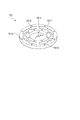
図2は、関節駆動装置71〜76の一例として、アーム20の関節駆動装置72の断面構造を示している。図2に示す構成は、アーム20の他の関節駆動装置71〜76にも用いられるものとする。後述する関節駆動装置72の各構成部材は、金属や樹脂など仕様上の強度や剛性に適合した材料から製造される。
FIG. 2 shows a cross-sectional structure of the
図2において、関節駆動装置72は、駆動機構の根本側部材(固定節)としてリンク62(第1のリンク)と、駆動機構の出力側部材(出力節)としてリンク63(第2のリンク)を含む。これらリンク62(固定節)と、リンク63(出力節)は、ハウジング部255に支持された関節支持機構としての軸受54によって回転自在に連結することによって構成されている。
In FIG. 2, a
軸受54は、駆動軸周りの回転運動のみが可能なように、リンク63のリンク62に対する相対回転運動を拘束する。軸受54は、リンク63に作用する6次元の(並進)力、およびモーメントのうち、関節駆動軸周りの回転トルク以外の5つの力・モーメント(図2)を支持する機能を有する。軸受54には、例えばロボットの関節機構などに広く用いられているクロスローラ軸受を用いることができるが、これに限らず他の同様の機能を有する軸受部材を用いることができる。
The
図2において、矢印90は、リンク63に作用する力を示している。このリンク63に作用する力(90)は、下記の成分の合成と考えることができる。
・この関節に関して計測すべき回転トルク(z軸廻り)901
・リンク63に作用する他軸力の回転モーメント成分(x方向)902
・リンク63に作用する他軸力の回転モーメント成分(y方向)903
・リンク63に作用する他軸力の並進力成分(x方向)904
・リンク63に作用する他軸力の並進力成分(y方向)905
・リンク63に作用する他軸力の並進力成分(z方向)906
In FIG. 2, an
・ Rotation torque (around z axis) 901 to be measured for this joint
A rotational moment component (x direction) 902 of the other axial force acting on the
A rotational moment component (y direction) 903 of the other axial force acting on the
A translational force component (x direction) 904 of the other axial force acting on the
A translational force component (y-direction) 905 of the other axial force acting on the
A translational force component (z direction) 906 of the other axial force acting on the
下記の回転駆動源51を駆動することによって、回転トルク(z軸廻り)901が発生され、のリンク62に対してリンク63の相対姿勢(角度)が制御される。その際、関節支持機構としての軸受54が、上記の他軸力902〜906を支持しつつ、関節軸(1点鎖線)廻りの関節の回転運動を規制する。
By driving the rotation drive
関節駆動装置72は、この関節の回転駆動源51および減速機構53から成る駆動部80を収容する全体がほぼ円筒形状のハウジング部55を含む。このハウジング部55には、上記の関節の駆動に必要な部材とともに、出力トルクの計測に必要な各構成要素が格納される。
The
本実施例では、ある構成部材が他の構成部材とリジッドに固定される場合、その結合(固定)部位を「固定部」という。この「固定部」の結合(固定)には、ネジ止め(詳細不図示)などの手法が用いられる。例えば、固定部551はハウジング部55の一部であって、ハウジング部55は固定部551を介して関節駆動装置72の根本側のリンク62に固定される。
In this embodiment, when a certain component is rigidly fixed to another component, the coupling (fixing) portion is referred to as a “fixing portion”. A method such as screwing (not shown in detail) or the like is used for coupling (fixing) of the “fixed portion”. For example, the fixing
本実施例のハウジング部55は、(第2の)リンク63を回転自在に支持する軸受54を有する。また、ハウジング部55は、(第2の)リンク63を回転駆動する駆動部80を収容する。特に、駆動部80は、次のように回動(駆動)軸が一致するように、ハウジング部55内に支持される。まず、駆動部80の回転駆動源51の駆動軸51aは、減速機構53の入力端531と結合される。また、減速機構53は、波動歯車機構などから成り、入力端531と出力端533は同軸配置であり、出力端533にはリンク63の回動軸が結合される。
The
駆動部80とハウジング部55の間には、ハウジング部55に対して駆動部80を支持する支持部(532、56、52)が設けられる。この支持部には、減速機構53の固定部532、回転駆動源51の保持部材56、およびトルク検出装置52が含まれる。保持部材56および固定部532は全体として円環状(フランジ状)の部材であって、その表裏面にはほぼ円筒状の外形を有する回転駆動源51ないし減速機構53の前端や後端を収容する凹部(あるいは透孔)が必要に応じて形成されているものとする。
Between the driving
回転駆動源51は保持部材56に対して例えばビス(不図示)止めなどにより固着され、保持部材56は減速機構53の固定部532に対して例えばビス(不図示)止めなどにより固着される。これにより、回転駆動源51と減速機構53が一体に結合(固着)され、駆動部80が構成される。
The
そして、駆動部80は、トルク検出装置52を介してハウジング部55と結合(固着)される。また、出力節である第2のリンク63は、ハウジング部55に装着された軸受54を介して回動自在であり、リンク63の駆動軸は減速機構53の出力端533と結合されている。
Then, the
以上のようにして、駆動部80は、支持部(減速機構53の固定部532〜回転駆動源51の保持部材56〜トルク検出装置52)と、ハウジング部55に装着された軸受54によってハウジング部55内に収容、支持される。即ち、駆動部80は、支持部(減速機構53の固定部532〜回転駆動源51の保持部材56〜トルク検出装置52)と、軸受54によって、円筒状のハウジング部55の中心線と駆動軸線が一致するよう、ハウジング部55の中心位置に収容、支持される。
As described above, the
以下、ハウジング部55に格納される構成要素の構成および配置の詳細と、関節の駆動とトルク計測の動作原理につき、説明する。
Hereinafter, the details of the configuration and arrangement of the components stored in the
回転駆動源51は、関節を回転させる回転力(トルク)を生成するもので、例えば電動モータ(サーボモータなど)によって構成する。回転駆動源51は、不図示のモータ回転角度計測用のロータリエンコーダ、モータ回転角度保持用のブレーキなどを備えている。また、回転駆動源51には、モータの電気的な駆動や、ロータリエンコーダとの信号の入出力、およびブレーキの開閉動作の制御などを行うモータ配線ケーブル572が接続されている。
The
減速機構53は、入力端531、出力端533、および、減速機構53の固定部532によって構成される。減速機構53の伝達機構は、例えば公知の波動歯車機構などによって構成される。本実施例では、減速機構53の減速比は例えば1:100程度であるものとする。
The
回転駆動源51の出力は、減速機構53の入力端531を回転駆動し、減速機構53は、回転駆動源の発生するトルクを減速比分だけ拡大し(同時に回転角度を減速比分だけ減速して)、拡大された回転トルクを出力端533より出力する。これにより回転駆動源51で発生するトルクが関節の駆動に適したレベルに拡大され、減速機構53の出力トルクによって、軸受54により拘束されたリンク63が、残りの回転自由度(駆動軸周りの回転自由度)で能動的に駆動される。
The output of the rotation drive
ここで、通常、小型の電動モータが効率よく発生できるトルクは、関節の駆動に必要なトルクに比べて非常に小さく、一方、定格回転速度は関節の出力軸に求められる回転速度よりもかなり大きい。そのため、ほとんどのロボットでは、1:30〜1:200程度の高い減速比を有する減速機構(53)を使用するのが一般的である。このような小型モータと高減速比の減速機構(53)による構成は、構成をコンパクトにできる利点がある一方、減速機構(53)で摩擦と回転抵抗によるトルク損失が大きくなる問題もある。 Here, usually, the torque that can be efficiently generated by a small electric motor is very small compared to the torque required for driving the joint, while the rated rotation speed is considerably higher than the rotation speed required for the output shaft of the joint. . Therefore, in most robots, it is common to use a speed reduction mechanism (53) having a high speed reduction ratio of about 1:30 to 1: 200. The configuration using such a small motor and the reduction mechanism (53) having a high reduction ratio has an advantage that the configuration can be made compact, but also has a problem in that the torque loss due to friction and rotational resistance increases in the reduction mechanism (53).
このため、モータトルクの測定、例えばモータトルクに比例するモータ電流の測定だけでは、関節の出力段に出力している回転トルクを正確に把握することができない。また、減速機構などの駆動系廻りでのトルク損失は、摩擦などの非線形な物理現象が主な要因であるため、精密なモデリングが困難であり、再現性も乏しい。従って、モータ電流を介して検出したモータトルク値を補正して、実際の出力トルクを演算するような処理は極めて困難である。従って、正確なトルク検出に基づく関節制御が必要であれば、トルク検出装置を設けて関節駆動装置の出力トルクを計測する必要がある。 For this reason, the measurement of the motor torque, for example, only the measurement of the motor current proportional to the motor torque, cannot accurately grasp the rotational torque output to the output stage of the joint. Further, since torque loss around a drive system such as a speed reduction mechanism is mainly caused by non-linear physical phenomena such as friction, precise modeling is difficult and reproducibility is poor. Therefore, it is very difficult to correct the motor torque value detected via the motor current and calculate the actual output torque. Therefore, if joint control based on accurate torque detection is required, it is necessary to provide a torque detection device and measure the output torque of the joint drive device.
本実施例では、上記のように駆動部80は、支持部(減速機構53の固定部532〜回転駆動源51の保持部材56〜トルク検出装置52)と、ハウジング部55に装着された軸受54によってハウジング部55内に収容、支持する構成を採用している。そして、本実施例では、この支持部に配置したトルク検出装置52によって、この支持部に発生するトルクを検出する。
In this embodiment, as described above, the driving
上記のように関節駆動装置72の駆動部80は回転駆動源51と減速機構53から構成される。そして、図2に示すように、減速機構53の固定部532は、保持部材56を介してトルク検出装置52に結合される。さらにトルク検出装置52は、ハウジング部55の内面に設けたフランジ部55aに例えばネジ止め(詳細不図示)などによって結合(固着)される。
As described above, the driving
本実施例において、駆動部80の支持部(減速機構53の固定部532〜回転駆動源51の保持部材56〜トルク検出装置52)は、駆動部80を一体化し、かつ軸受54とともに駆動部80をハウジング部55内に支持する。
In the present embodiment, the support portion of the drive unit 80 (the fixed
トルク検出装置52の構成例を図5に示す。図5のトルク検出装置52は、外装部材(カバー)522、および弾性体521によって構成されている。外装部材522、および弾性体521は、図示のように円環(リング)状の全体形状を有し、駆動部80(の保持部材56)、およびハウジング部55のフランジ部55aと結合するためのネジ孔521a、521bを有する。
FIG. 5 shows a configuration example of the
また、トルク検出装置52は、トルクセンサ52s(図2)の出力を導出するセンサ配線ケーブル571を備えている。センサ配線ケーブル571は、図2に示すように、第1のリンク62(固定節)のケース621の内部に配置された関節コントローラ57と結線される。また、関節コントローラ57は、モータ配線ケーブル572によって、回転駆動源51と結線されている。この関節コントローラ57は、ケーブル40によって制御装置3と接続され、トルク検出装置52は、トルクセンサ52sの出力を制御装置3(のインターフェース33)に送信するとともに、制御装置3が駆動部80を制御する駆動信号を受信する。
Further, the
ここで、関節駆動装置(72)のリンク62、63の相対姿勢が所定角度となるよう、あるいはこれらリンクを特定の相対姿勢で維持するように、駆動部80を駆動することを考える。この時、トルク検出装置52の配置(図2)から明らかなように、トルク検出装置52の弾性体521は駆動部80の駆動トルクの反力を受けてその大きさに応じて変形する。弾性体521の変形をトルクセンサ52s(図2)で検出することにより、駆動部80の支持部(減速機構53の固定部532〜回転駆動源51の保持部材56〜トルク検出装置52)に生じているトルクを検出できる。トルクセンサ52sは、光学センサや磁気センサなど、任意の検出方式を利用したセンサデバイスにより構成することができる。このトルク値は、駆動部80の発生している関節駆動装置(72)の駆動(実)トルクとして取り扱うことができる。
Here, it is considered that the driving
図5のトルク検出装置52の弾性体521は、例えば図6のような構成とすることができる。図6の弾性体521は、内輪部5212、外輪部5211と、これらを結合するスポーク状の弾性変形部5213から成る。内輪部5212、および外輪部5211は、それぞれ駆動部80(の保持部材56)、およびハウジング部55のフランジ部55aと結合するためのネジ孔521a、521bを有する。即ち、弾性体521は、その内周側において駆動部80に固定され、外周側はハウジング部55の内面に固定されている。
The
トルクセンサ52s(図2)は、例えば弾性変形部5213の変形量を検出するよう装着される。これによりトルクセンサ52s(図2)を介して駆動部80の支持部(減速機構53の固定部532〜回転駆動源51の保持部材56〜トルク検出装置52)に生じるトルク(図2のZ軸周りの回転モーメント)を測定することができる。
The
図5、図6のように構成されたトルク検出装置52は、関節駆動装置72の駆動部80が出力するトルクの反作用(反トルク)を受けて、この反トルクを介して駆動部80の駆動トルクを検出することができる。
The
即ち、本実施例の構成では、第1のリンク62(固定節)に対して相対回転する第2のリンク63(出力節)側にトルク検出手段を搭載していない。そして、本実施例では、第1リンク62の側(ハウジング部55〜駆動部80間))にトルク検出装置52を配置しながらも、関節駆動装置(72)の出力するトルクを計測することができる。
That is, in the configuration of the present embodiment, no torque detecting means is mounted on the side of the second link 63 (output node) that rotates relative to the first link 62 (fixed node). In the present embodiment, it is possible to measure the torque output from the joint driving device (72) while disposing the
そして、本実施例の構成では、センサ配線ケーブル571(図2)は関節駆動装置(72)の可動部をまたいで設置する必要がない。このため、センサ配線ケーブル571の引き回しが不要となり、その結果、駆動機構全体が簡潔かつコンパクトな構成となり、ひいてはロボット装置全体を軽量化することが可能になる。また、関節駆動装置(72)の回転運動にともなうセンサ配線ケーブル571の変形も考慮する必要がなく、例えばセンサ配線ケーブル571の変形抵抗によるトルク検出精度の低下を防ぐことができる。また、センサ配線ケーブル571の繰り返し変形とケーブルとケーブル支持部材間の摺動によるケーブルの寿命低下を防ぐことができ、ロボット装置の信頼性を大きく向上させることができる。
In the configuration of the present embodiment, the sensor wiring cable 571 (FIG. 2) does not need to be installed across the movable part of the joint driving device (72). For this reason, the wiring of the
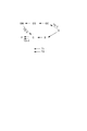
また、本実施例によれば、他軸力の外乱の影響なく、関節駆動装置(72)の駆動部80の駆動トルクを検出することができる。ここで、図10は、本実施例の関節駆動装置(72)のリンク63(出力節)に作用する力、およびモーメントの伝達経路を示している。図10は、図2に相当する関節駆動装置(72)と同等の構成を模式的に示している。ここでは、各部に作用する力および図2に相当する部材は大文字のアルファベットで示し、上記の参照符号との対応は括弧書きで示している。
Further, according to the present embodiment, it is possible to detect the driving torque of the driving
また、図12は、図10の上記各部材間の力の伝達経路を抜き出して矢印によって示している。図12中の破線の経路T1、および実線の経路T2は、図11中の経路T1、T2にそれぞれ相当する。 FIG. 12 shows a force transmission path between the above-mentioned members in FIG. 10 by arrows. A path T1 indicated by a broken line and a path T2 indicated by a solid line in FIG. 12 correspond to the paths T1 and T2 in FIG. 11, respectively.
図10、図12において、Oは出力節(リンク63)、Bは関節支持機構(軸受54)、GOは駆動部(80:回転駆動源51および減速機構53)の出力を示す。また、GSは駆動部(80)の固定部(532)、GIは駆動部(80)の入力端(531)を示す。また、Mは回転駆動源(51)、Cはハウジング部(55)、GMはの固定部材、Fはハウジングの固定節(リンク62)への固定部、TSはトルク検出装置(52)を示す。
10 and 12, O indicates an output node (link 63), B indicates a joint support mechanism (bearing 54), and GO indicates an output of a drive unit (80: the
図10、図12において、出力節(リンク63)には、図2で上述した通り、ロボット装置の運動によって6次元の(並進)力、およびモーメント(902〜906)が作用する。本実施例において、トルク検出装置で計測したいのは、関節駆動軸周りの回転トルク901である。それ以外の他軸力(902〜906)は、トルク検出装置にとってクロストークの元になる外乱力である。
10 and 12, a six-dimensional (translational) force and a moment (902 to 906) act on the output node (link 63) by the motion of the robot apparatus as described above with reference to FIG. In the present embodiment, what is desired to be measured by the torque detecting device is the
上述のように外乱力(関節駆動軸周りの回転トルク以外の5つの力・モーメント(902〜906))は、軸受54(関節支持機構)によって支持される。従って、図10に示すように、出力に作用する他軸外乱力は軸受を介してハウジング部によって支持され、根元側の固定節(リンク62)へ伝達されることになる(図中、経路T2)。 As described above, the disturbance force (five forces / moments (902 to 906) other than the rotational torque around the joint drive shaft) is supported by the bearing 54 (joint support mechanism). Therefore, as shown in FIG. 10, the other-axis external disturbance force acting on the output is supported by the housing via the bearing and transmitted to the fixed node (link 62) on the root side (path T2 in the figure). ).
そして、駆動部80(回転駆動源51および減速機構53)を介してトルク検出装置TS(52)に作用する力は、図中の経路T1を経由する力となるが、この力は上記の外乱を含まない関節駆動軸周りのトルクのみとなる。特に図12において、本実施例の関節駆動トルク(TS−1)は、破線で示すように伝達され、経路TS−3(図10のトルク検出装置TSに相当)を通り、ハウジング部(C)に伝わる。この経路(T1:破線)は、他軸外乱力の経路(T2:実線)と分離されており、トルク検出装置TS(図10、52)は他軸外乱力の影響を受けない。
Then, the force acting on the torque detecting device TS (52) via the drive unit 80 (the
ここで、本実施例と対比するため、従来の関節駆動装置の力の伝達の様子を図11に示す。図11では図10と同等のアルファベット符号により各部および力を示してある。 Here, for comparison with the present embodiment, a state of transmission of the force of the conventional joint driving device is shown in FIG. In FIG. 11, the components and the forces are indicated by the same alphabetical symbols as in FIG.
図11の関節駆動装置では、トルク検出装置TSは固定節(F)とハウジング(C)の間に配置されている。このため、図11の関節駆動装置では、トルク検出装置TSには、検出すべき関節駆動軸周りのトルク(経路T1)とともに、他軸力(経路T2)が直接的に作用する構成となっている。そのため、図11の構成では、他軸力のクロストークが大きく、正確なトルク検出が困難である。 In the joint driving device of FIG. 11, the torque detecting device TS is disposed between the fixed joint (F) and the housing (C). For this reason, in the joint driving device of FIG. 11, the torque detecting device TS is configured such that the other axial force (path T2) directly acts on the torque (path T1) around the joint driving axis to be detected. I have. Therefore, in the configuration of FIG. 11, crosstalk of the other axial force is large, and accurate torque detection is difficult.
例えば、図12において経路TS−2は図11のトルク検出装置TSに相当し、この経路は、関節駆動軸周りのトルク(破線)と他軸力のクロストーク(実線)で共有されてしまっている。即ち、図11の従来構成では、トルク検出装置TSで、検出すべき関節駆動軸周りのトルク(破線)を他軸力のクロストーク(実線)と分離して検出することができない。 For example, in FIG. 12, a path TS-2 corresponds to the torque detection device TS in FIG. 11, and this path is shared by the torque (broken line) around the joint drive shaft and the crosstalk (solid line) of the other axial force. I have. That is, in the conventional configuration of FIG. 11, the torque detection device TS cannot detect the torque (broken line) around the joint drive shaft to be detected separately from the crosstalk (solid line) of the other axial force.
一方、本実施例の関節駆動装置は、図10、図12に示したように他軸外乱力がトルク検出装置(TS、52)に作用しない構成となっているため、他軸干渉クロストークの影響を受けずに正確に関節の駆動トルクを検出することができる。さらに、本実施例の構成によれば、従来技術(例えば特許文献1)にトルクセンサや駆動部の支持のための追加の支持機構を必要としない。従って、ロボットアームの関節部全体の構成が簡潔かつコンパクトなものとなり、駆動機構全体の軽量化、および剛性の確保を行うことが容易である。これにより、ひいてはロボット装置全体の軽量化が可能となるため、ロボットの応答性と俊敏性を向上させることが可能な構成になっている。 On the other hand, the joint drive device of the present embodiment has a configuration in which the external-axis disturbance force does not act on the torque detection device (TS, 52) as shown in FIGS. The drive torque of the joint can be accurately detected without being affected. Further, according to the configuration of the present embodiment, the conventional technology (for example, Patent Document 1) does not require an additional support mechanism for supporting the torque sensor and the driving unit. Therefore, the configuration of the entire joint portion of the robot arm is simple and compact, and it is easy to reduce the weight and secure the rigidity of the entire drive mechanism. As a result, the weight of the entire robot device can be reduced, and the responsiveness and agility of the robot can be improved.
ここで、本実施例における関節駆動装置の他軸干渉の度合いを、具体的な数値に基づいて計算した結果によって示す。ここでは、トルク検出装置52(の弾性体521)が関節の出力トルクによって弾性変形する変形量と、ハウジング部が他軸力によって変形する変形量を計算し、その量を比較する。
Here, the degree of the other axis interference of the joint driving device according to the present embodiment is shown by a result calculated based on specific numerical values. Here, the amount of deformation of the torque detecting device 52 (the
この計算例では、搬送質量2kg程度の小型の垂直多関節型のロボットへの適用を想定する。トルク検出装置52の弾性体521のトルク計測方向(図2のz軸方向)のねじり剛性Kは、20、000Nm/rad程度とする(これは減速機の剛性に比べて十分に大きなものになっている)。トルク検出装置52は、弾性体521(図6)の外輪部5211に対する内輪部5212の変形量をトルクセンサ(52s)により計測することによってトルクを計測する。
In this calculation example, it is assumed that the present invention is applied to a small vertical articulated robot having a transfer mass of about 2 kg. The torsional rigidity K of the
光学ないし磁気センサなどを利用した変位計測センサにより構成されるトルクセンサ(52s)は、ここでは、弾性体521に対して例えば半径R=30mmの円周(ないし円弧)の範囲に装着されるものとする。
Here, a torque sensor (52s) constituted by a displacement measuring sensor using an optical or magnetic sensor is mounted on the
ここで、図2の関節駆動装置(72)に作用する並進力の最大値Pは、ロボットが押しつけ作業を行う際や加減速運動を行う際を考慮すると、x方向に関して300N程度である。同様に、関節に作用するトルクTは50Nm程度である。また、図2においてハウジング部の外径Dは90mm、ハウジングの内径dは85mmであり、材質はアルミ合金(縦弾性係数E=90Gpa)である。また関節を支持する軸受54からトルク検出装置52の設置位置までの距離Lは30mmである。
Here, the maximum value P of the translational force acting on the joint driving device (72) in FIG. 2 is about 300N in the x direction when the robot performs a pressing operation or performs an acceleration / deceleration motion. Similarly, the torque T acting on the joint is about 50 Nm. In FIG. 2, the outer diameter D of the housing part is 90 mm, the inner diameter d of the housing is 85 mm, and the material is an aluminum alloy (longitudinal elasticity coefficient E = 90 Gpa). The distance L from the bearing 54 supporting the joint to the installation position of the
このとき、関節が定格トルクを出力している際のトルクセンサ52sの内輪の変形量dXTは、以下の式(1)のように表わせる。
In this case, the deformation amount dX T of the inner ring of the
![]()
![]()
ここでハウジング部を単純な円筒系の断面を有する梁としてモデリングすると、その断面2次モーメントIは以下の式(2)のように表わせる。 If the housing is modeled as a beam having a simple cylindrical cross section, its second moment of area I can be expressed as the following equation (2).
![]()
![]()
従って、他軸力の最大値Pによるトルクセンサ52sの変位検出部の変形量dXdisは、以下の式(3)のように表わせる。
Therefore, the deformation amount dX dis of the displacement detection unit of the
![]()
![]()
以上のように、本実施例の構成では、トルク計測によってセンサ弾性体が変形する変形量と他軸外乱力によって生じる弾性体の変形量には、3000倍以上の差があることが分かる。即ち、本実施例では、他軸力によるクロストークの影響を殆ど受けずに関節の駆動トルクを検出することができ、他軸力によるクロストークに影響されずにこの関節の駆動トルクを正確に検出することができる。 As described above, in the configuration of the present embodiment, it can be seen that there is a difference of 3000 times or more between the amount of deformation of the sensor elastic body by the torque measurement and the amount of deformation of the elastic body caused by the external-axis disturbance force. That is, in the present embodiment, it is possible to detect the drive torque of the joint almost without being affected by the crosstalk due to the other axial force, and to accurately detect the drive torque of this joint without being affected by the crosstalk due to the other axial force. Can be detected.
なお、以上に示した数値は本実施例における例示値に過ぎず、本発明を何ら限定するものではない。また、本実施例では、アーム20として6軸の垂直多関節アームを適用しているが、軸数は用途や目的に応じて適宜変更することができる。例えば、上述の関節駆動装置の構成はパラレルリンク形式のロボットアームの関節にも容易に実施することができる。また、図1においてアーム20のリンク61〜67としては、長さが固定されたものを採用しているが、例えば、直動アクチュエータなどを用いた伸縮可能なリンクを採用してもよい。
Note that the numerical values shown above are merely exemplary values in the present embodiment, and do not limit the present invention in any way. In the present embodiment, a six-axis vertical articulated arm is applied as the
また、本実施例では、軸受54(関節支持機構)には、単一の機構で所望の支持機能を実現できるクロスローラ軸受を使用しているが、支持機構の具体的な構成はこれに限定されるものではない。例えば、複数のアンギュラ軸受を使用してもよいし、他の形態の軸受機構を組み合わせ、関節支持機能を実現してもよい。さらに、減速機構53の減速比として、1:100を例示したが、これに限定されることなく、減速機構53の減速比は任意の値に設定してよい。
In this embodiment, the bearing 54 (joint support mechanism) uses a cross roller bearing that can achieve a desired support function with a single mechanism, but the specific configuration of the support mechanism is not limited to this. It is not something to be done. For example, a plurality of angular bearings may be used, or a bearing mechanism of another form may be combined to realize a joint supporting function. Further, the reduction ratio of the
また、本実施例では、駆動部(関節トルク生成機構)80を電動モータのような回転駆動源51と波動歯車機構などによる減速機構53を組み合わせて構成した。しかしながら、関節の駆動部80の形態はこれに限定されるものではなく、例えば減速機構を用いないダイレクト駆動方式のモータを使ってもよい。また、エネルギ源は電動に限定されるものでもなく油圧などの流体駆動方式の駆動機構を用いる場合でも、上述同様の部材配置を実施することができる。
In this embodiment, the driving unit (joint torque generating mechanism) 80 is configured by combining a
図2および上記の式(3)に示したように、トルク検出装置52の弾性体521の外輪部5211の変形量は、ハウジング部55上の設置位置と関節を支持する軸受54の間の距離Lに大きく影響を受けることが判る。従って、トルク検出装置52弾性体521)を軸受54の近くに配置することができれば、他軸干渉量のさらなる低減が可能となる。
As shown in FIG. 2 and the above equation (3), the amount of deformation of the
例えば、図3に示すように、トルク検出装置52弾性体521)をハウジング部55へ取り付けるフランジ部55bの位置を図2の位置(55a)よりも軸受(関節支持機構)54に近い位置に配置する。そして、トルク検出装置52弾性体521)を、減速機構53の固定部532およびフランジ部55bの間に装着する。その他の構成は図2と同様である。
For example, as shown in FIG. 3, the position of the flange portion 55b for attaching the
図3の構成では、トルク検出装置52弾性体521)を、駆動部80の固定部(減速機構53の固定部532)と、ハウジング部55の間に配置するのは、第一の実施例と同様である。しかしながら、図3では、トルク検出装置52弾性体521)のハウジング部55への取り付け部位を、軸受(関節支持機構)54と駆動部80の間、特に第2のリンク63を支持する軸受54のより近傍に配置している。
In the configuration of FIG. 3, the
このように、トルク検出装置52のハウジング部55への取り付け部位を、軸受54により近い位置とし、軸受54のより近傍でトルク検出を行うことにより、他軸干渉量のさらなる低減が可能となり、より正確なトルク検出を行える。
As described above, the mounting position of the
上記実施例では、トルク検出装置52の弾性体521には円環(リング)形状のものを例示した。しかしながら、関節駆動装置(72)は、例えば図7〜図9に示すような異なる形状の弾性体を用いたトルク検出装置52を用いて図4のように構成してもよい。
In the above embodiment, the
本実施例では、図7に示すようなトルク検出装置52を用いる。トルク検出装置52は、弾性体521と、それを保護する外装部材(カバー)522、およびセンサ配線ケーブル571を備え、全体がほぼ円筒状の外形を有する。
In this embodiment, a
弾性体521は、図8に示すように、第1の固定部としてフランジ5211a、第2の固定部としてフランジ5212aを有する。フランジ5211a、5212aは円筒状の弾性変形部5213で結合され図9に示すような断面形状に一体化されている。
As shown in FIG. 8, the
図7〜図9のように構成されたトルク検出装置52は、図4のように関節駆動装置(72)に組み込む。即ち、トルク検出装置52のフランジ5211aは駆動部80の保持部材56に固定し、フランジ5212aはハウジング部の第1のリンク62側の内面に固定する。光学センサや磁気センサなどから成るトルクセンサ(52s:不図示)は弾性変形部5213のねじれ、ないしフランジ5211a、および5212aの相対変位を検出できるよう、例えば弾性変形部5213の内面(ないし外面)の適当な位置に配置する。
The
以上のように、トルク検出装置52を円筒状の弾性体521により構成し、その一端を実施例1と同様に駆動部80の保持部材56に固定し、他端はハウジング部55の第1のリンク62側の内面に固定する。関節駆動装置(72)のその他の構成は実施例1(図2)と同様である。
As described above, the
本実施例によれば、円筒状の弾性体521(弾性変形部5213)のねじり変形量(あるいは歪み量)を計測することで、トルク(図に示すZ軸周りの回転モーメント)を測定することができる。これにより、実施例1と同様に他軸干渉(クロストーク)の影響を受けずに、正確に関節駆動トルクを検出することができる。特に、本実施例ではトルク検出装置52の円筒状の弾性体521(弾性変形部5213)の一端を他軸力によって殆んど変形しないハウジング部55の基底部(リンク62側)に固定している。このため、他軸干渉(クロストーク)の影響を受けずに、正確に関節駆動トルクを検出することができる。
According to this embodiment, by measuring the amount of torsional deformation (or the amount of distortion) of the cylindrical elastic body 521 (elastic deformation portion 5213), the torque (rotational moment around the Z axis shown in the figure) can be measured. Can be. As a result, the joint drive torque can be accurately detected without being affected by the interference of other axes (crosstalk) as in the first embodiment. In particular, in this embodiment, one end of the cylindrical elastic body 521 (elastic deformation portion 5213) of the
また、本実施例によれば、トルク検出装置52の構造を簡略化でき、トルク検出装置52を小型軽量化し、その製造コストを大きく低減することができる。特に、トルク検出装置52の弾性体521(弾性変形部5213)を円筒状に構成することによって、駆動部80の回転駆動源51周囲のスペースを利用してトルク検出装置52を関節駆動装置(72)内に実装することができる。また、トルク検出装置52の弾性体521は比較的大きなサイズに構成することができ、その変形を検出するトルクセンサには分解能のそれ程高くない安価な部品を利用できる可能性がある。
Further, according to the present embodiment, the structure of the
1…ロボット装置、2…ロボット本体、3…制御装置、20…アーム、30…CPU、71〜76…関節駆動装置、51…回転駆動源(モータ)、52…トルク検出装置、521…弾性体、53…減速機構、531…入力端、532…固定部、533…出力端、54…軸受(関節支持機構)、55…ハウジング部、551…固定部、56…保持部材、57…関節コントローラ、571…センサ配線ケーブル、572…モータ配線ケーブル、62…リンク(第1のリンク)621…固定節のケース、63…リンク(第2のリンク)72…関節駆動装置、80…駆動部、90…出力節へ作用する力、901…関節が計測すべき回転トルク(z方向)、902…出力節へ作用する他軸力の回転モーメント成分(y方向)、903…出力節へ作用する他軸力の回転モーメント成分(x方向)、904…出力節へ作用する他軸力の並進力成分(x方向)、905…出力節へ作用する他軸力の並進力成分(y方向)、906…出力節へ作用する他軸力の並進力成分(z方向)。
DESCRIPTION OF
Claims (11)
リンクを回転させる駆動部と、
前記筐体部に設けられ、前記筐体部と前記リンクとを連結し、前記リンクを回転可能に支持する軸受と、
前記筐体部と前記駆動部とを連結し、前記駆動部を前記筐体部に対して支持する支持部
と、
前記駆動部が、前記筐体部に対して、前記リンクの回転と同じ軸方向周りに相対的に変位した際、前記支持部の変形を検出するセンサと、を備え、
前記駆動部は、駆動源と、減速機と、接続部と、を備えており、前記駆動源と前記減速機との間に前記接続部が設けられることで前記駆動源と前記減速機とが連結され、
前記支持部は、前記筐体部の内部かつ前記駆動部と前記筐体部との間に設けられ、前記接続部と前記筐体部とを連結することで、前記筐体部に対して前記駆動部を支持している、
ことを特徴とする駆動装置。 A housing part,
A drive unit for rotating the link,
A bearing that is provided on the housing, connects the housing and the link, and rotatably supports the link;
A support unit that connects the housing unit and the drive unit, and supports the drive unit with respect to the housing unit;
When the drive unit is relatively displaced around the same axial direction as the rotation of the link with respect to the housing unit, the sensor includes a sensor that detects deformation of the support unit ,
The drive unit includes a drive source, a speed reducer, and a connection unit, and the drive source and the speed reducer are provided by providing the connection unit between the drive source and the speed reducer. Concatenated,
The support section is provided inside the housing section and between the driving section and the housing section, and connects the connection section and the housing section to each other, whereby the support section is Supporting the drive,
Driving device comprising a call.
Priority Applications (4)
| Application Number | Priority Date | Filing Date | Title |
|---|---|---|---|
| JP2015050123A JP6632204B2 (en) | 2015-03-13 | 2015-03-13 | Driving device, robot device, and article manufacturing method |
| CN201610128482.8A CN105965504B (en) | 2015-03-13 | 2016-03-08 | Joint driving device and robot device |
| EP16159566.5A EP3067164B1 (en) | 2015-03-13 | 2016-03-10 | Joint driving apparatus and robot apparatus |
| US15/067,686 US10335959B2 (en) | 2015-03-13 | 2016-03-11 | Joint driving apparatus and robot apparatus |
Applications Claiming Priority (1)
| Application Number | Priority Date | Filing Date | Title |
|---|---|---|---|
| JP2015050123A JP6632204B2 (en) | 2015-03-13 | 2015-03-13 | Driving device, robot device, and article manufacturing method |
Publications (2)
| Publication Number | Publication Date |
|---|---|
| JP2016168647A JP2016168647A (en) | 2016-09-23 |
| JP6632204B2 true JP6632204B2 (en) | 2020-01-22 |
Family
ID=55661145
Family Applications (1)
| Application Number | Title | Priority Date | Filing Date |
|---|---|---|---|
| JP2015050123A Active JP6632204B2 (en) | 2015-03-13 | 2015-03-13 | Driving device, robot device, and article manufacturing method |
Country Status (4)
| Country | Link |
|---|---|
| US (1) | US10335959B2 (en) |
| EP (1) | EP3067164B1 (en) |
| JP (1) | JP6632204B2 (en) |
| CN (1) | CN105965504B (en) |
Families Citing this family (34)
| Publication number | Priority date | Publication date | Assignee | Title |
|---|---|---|---|---|
| GB2540756B (en) | 2015-07-22 | 2021-03-31 | Cmr Surgical Ltd | Gear packaging for robot arms |
| EP3325223B1 (en) | 2015-07-22 | 2022-05-11 | CMR Surgical Limited | Gear packaging for robot arms |
| GB2540757B (en) * | 2015-07-22 | 2021-03-31 | Cmr Surgical Ltd | Torque sensors |
| GB2541369B (en) | 2015-07-22 | 2021-03-31 | Cmr Surgical Ltd | Drive mechanisms for robot arms |
| JP6752576B2 (en) * | 2016-01-13 | 2020-09-09 | キヤノン株式会社 | Drive mechanism, robot device, control method of drive mechanism, control method of robot device, manufacturing method of article, control program, recording medium, and support member |
| JP6501746B2 (en) * | 2016-10-07 | 2019-04-17 | キヤノン株式会社 | Displacement measuring device, robot, robot arm and method of manufacturing article |
| JP2018075674A (en) * | 2016-11-10 | 2018-05-17 | ソニー株式会社 | Joint driving actuator |
| US10444098B2 (en) | 2017-04-10 | 2019-10-15 | Fanuc Corporation | Torque sensor and robot |
| JP2018202504A (en) | 2017-05-31 | 2018-12-27 | ソニー株式会社 | Medical support arm system, method of controlling medical support arm, and control device of medical support arm |
| EP3418007A1 (en) * | 2017-06-19 | 2018-12-26 | ABB Schweiz AG | Method of determining a joint torque in a joint of an articulated industrial robot |
| CA176118S (en) * | 2017-07-28 | 2018-09-20 | Genesis Robotics Llp | Robotic arm |
| CN107511849B (en) * | 2017-08-31 | 2024-03-01 | 广州泰行智能科技有限公司 | Fixing structure of cable |
| CN107435720A (en) * | 2017-09-07 | 2017-12-05 | 吴烈 | Driving joint, power arm and Versatile Construction Machinery |
| KR102003906B1 (en) * | 2017-10-25 | 2019-07-25 | 고려대학교 산학협력단 | Robot articulation unit having joint torque sensor |
| WO2019083302A1 (en) * | 2017-10-25 | 2019-05-02 | 고려대학교 산학협력단 | Joint torque sensor and robot joint unit including same |
| EP3705018A4 (en) * | 2017-11-01 | 2020-10-14 | Sony Corporation | Surgical arm system and surgical arm control system |
| USD890238S1 (en) * | 2018-03-02 | 2020-07-14 | Abb Schweiz Ag | Joint for an industrial robot |
| DE102018107142A1 (en) * | 2018-03-26 | 2019-09-26 | M-Robot OHG | manipulator device |
| USD883351S1 (en) * | 2018-05-10 | 2020-05-05 | Robotiq Inc. | Robotic end effector |
| DE102018213452A1 (en) * | 2018-08-09 | 2020-02-13 | Kuka Deutschland Gmbh | Robotic arm with at least one joint torque sensor |
| CN108920880B (en) * | 2018-08-14 | 2023-06-09 | 合肥哈工图南智控机器人有限公司 | Motor and speed reducer type selection method of intelligent driving unit |
| US11045950B2 (en) * | 2018-11-02 | 2021-06-29 | Canon Kabushiki Kaisha | Driving device and detecting device |
| GB201915013D0 (en) * | 2019-10-17 | 2019-12-04 | Genesis Robotics And Motion Tech Lp | Actuator arrangement |
| JP2020116693A (en) * | 2019-01-24 | 2020-08-06 | キヤノン株式会社 | Joint device, robot arm, torque and rotation angle detection device, and article manufacturing method |
| EP3927496A4 (en) | 2019-02-20 | 2022-06-29 | Harmonic Bionics, Inc. | Actuator for physical therapy |
| JP7319105B2 (en) * | 2019-06-27 | 2023-08-01 | ファナック株式会社 | Rotary axis structure and robot |
| DE102019119658A1 (en) * | 2019-07-19 | 2021-01-21 | Pilz Gmbh & Co. Kg | Cycloid gear with torque detection device |
| JP7303702B2 (en) * | 2019-08-21 | 2023-07-05 | 住友重機械工業株式会社 | robot |
| CN115298000A (en) | 2020-03-18 | 2022-11-04 | 发那科株式会社 | Rotating shaft structure with force sensor and robot |
| CN116963880A (en) * | 2021-03-03 | 2023-10-27 | 住友重机械工业株式会社 | Connecting device and manipulator |
| CN113183148A (en) * | 2021-03-31 | 2021-07-30 | 成都飞机工业(集团)有限责任公司 | Industrial robot singularity-avoiding end effector connecting device and singularity-avoiding method |
| US11541530B1 (en) | 2021-09-30 | 2023-01-03 | Harmonic Bionics, Inc. | Compliant mechanism for improving axial load sensing in robotic actuators |
| CN113618702B (en) * | 2021-10-12 | 2022-03-18 | 深圳市越疆科技有限公司 | Teleoperation manipulator and rocker arm structure thereof, teleoperation equipment |
| JP2023095023A (en) | 2021-12-24 | 2023-07-06 | キヤノン株式会社 | Robot, manufacturing method and distributed sensor |
Family Cites Families (22)
| Publication number | Priority date | Publication date | Assignee | Title |
|---|---|---|---|---|
| JPS582800B2 (en) * | 1979-02-28 | 1983-01-18 | 株式会社明電舎 | Actuation force detection device for manipulators, etc. |
| JPS6133892A (en) * | 1984-07-26 | 1986-02-17 | 株式会社東芝 | Method of measuring driving torque of joint of robot |
| JPS6150030A (en) * | 1984-08-18 | 1986-03-12 | Omron Tateisi Electronics Co | Thin type force detector |
| US5155423A (en) * | 1986-02-18 | 1992-10-13 | Robotics Research Corporation | Industrial robot with servo |
| JPS63185535U (en) * | 1987-05-21 | 1988-11-29 | ||
| JPH05223665A (en) * | 1992-02-18 | 1993-08-31 | Fujitsu Ltd | Torque detection part of motor |
| US5327790A (en) * | 1992-06-19 | 1994-07-12 | Massachusetts Institute Of Technology | Reaction sensing torque actuator |
| JP3324298B2 (en) * | 1994-10-19 | 2002-09-17 | 株式会社豊田中央研究所 | Manipulator control device |
| JP3644558B2 (en) * | 1995-11-02 | 2005-04-27 | 株式会社ハーモニック・ドライブ・システムズ | Torque detection mechanism of flexure meshing gear unit |
| JP3624374B2 (en) * | 2000-12-12 | 2005-03-02 | 独立行政法人産業技術総合研究所 | Force display device |
| JP4273335B2 (en) * | 2004-06-16 | 2009-06-03 | 独立行政法人産業技術総合研究所 | Robot arm |
| DE102007005894A1 (en) * | 2006-06-14 | 2007-12-20 | GIF Gesellschaft für Industrieforschung mbH | torque flange |
| JP4230500B2 (en) * | 2006-09-07 | 2009-02-25 | 豊田鉄工株式会社 | Load detection device |
| CN101539464B (en) * | 2009-04-17 | 2010-09-22 | 北京航空航天大学 | Elastic torsion shaft |
| JP5218524B2 (en) * | 2010-03-15 | 2013-06-26 | 株式会社安川電機 | Robot system and robot operation restriction method |
| JP2011209099A (en) | 2010-03-30 | 2011-10-20 | Sony Corp | Torque sensor and robot apparatus |
| JP2012047460A (en) | 2010-08-24 | 2012-03-08 | Sony Corp | Torque detection device and robot device |
| CN102494819A (en) * | 2011-11-29 | 2012-06-13 | 北京邮电大学 | Joint torque sensor based on elastic beam |
| DE102012202181A1 (en) * | 2012-02-14 | 2013-08-29 | Kuka Roboter Gmbh | Method for determining a torque and industrial robots |
| US9293962B2 (en) * | 2012-03-30 | 2016-03-22 | Korea Institute Of Machinery & Materials | Hollow driving module |
| KR101194313B1 (en) * | 2012-03-30 | 2012-10-26 | 한국기계연구원 | Driving modules with hollowness |
| CN103711741B (en) * | 2013-12-17 | 2015-10-28 | 东南大学 | A kind of joint of robot rotating liquid cylinder pressure with moment of torsion and angle feed-back |
-
2015
- 2015-03-13 JP JP2015050123A patent/JP6632204B2/en active Active
-
2016
- 2016-03-08 CN CN201610128482.8A patent/CN105965504B/en active Active
- 2016-03-10 EP EP16159566.5A patent/EP3067164B1/en active Active
- 2016-03-11 US US15/067,686 patent/US10335959B2/en active Active
Also Published As
| Publication number | Publication date |
|---|---|
| EP3067164A2 (en) | 2016-09-14 |
| CN105965504A (en) | 2016-09-28 |
| US10335959B2 (en) | 2019-07-02 |
| US20160263749A1 (en) | 2016-09-15 |
| CN105965504B (en) | 2020-11-20 |
| EP3067164B1 (en) | 2021-07-28 |
| EP3067164A3 (en) | 2017-01-18 |
| JP2016168647A (en) | 2016-09-23 |
Similar Documents
| Publication | Publication Date | Title |
|---|---|---|
| JP6632204B2 (en) | Driving device, robot device, and article manufacturing method | |
| JP6752576B2 (en) | Drive mechanism, robot device, control method of drive mechanism, control method of robot device, manufacturing method of article, control program, recording medium, and support member | |
| JP7263412B2 (en) | Drive device, robot device, article manufacturing method, control method, control program, recording medium | |
| JP2009504418A (en) | CMM arm with enhanced manual control | |
| JP2005536703A (en) | Parallel manipulator | |
| US11148298B2 (en) | Arrangement for an articulated arm robot and method for determining the positioning of a mount for an end effector of an articulated arm robot | |
| CN212218476U (en) | Torque-controllable rotary driver and robot system | |
| JP5467290B2 (en) | Articulated robot system, articulated robot, force measurement module, force measurement method and program | |
| KR20100019495A (en) | Robotic manipulator using rotary drives | |
| KR101691941B1 (en) | Robot joint driving apparatus and joint torque measuring method of the same | |
| KR101715222B1 (en) | Robot coaxial articulation unit | |
| JP5467291B2 (en) | Energy-saving robot joint drive control system | |
| CN111683796A (en) | Mechanical arm and robot | |
| Tsetserukou et al. | Development of a whole-sensitive teleoperated robot arm using torque sensing technique | |
| US20190366537A1 (en) | Driving mechanism, robot apparatus, method for controlling driving mechanism, method of manufacturing an article using robot arm, and storage medium | |
| Fang et al. | A light weight arm designed with modular joints | |
| Rauniyar et al. | Design model for the drive and actuator of the test set-up of a novel flexible robotic system | |
| Sandakalum et al. | Design and characterization of a 1-axis compact torque sensor for a collaborative robot arm | |
| WO2023243241A1 (en) | Force-controlled actuator | |
| Smith | An Analysis of Critically Enabling Technologies for Force and Power Limiting of Industrial Robotics | |
| JP2020015146A (en) | Robot arm and robot device | |
| Park et al. | Robot joint module with a reactive-type joint torque sensor | |
| US20230266186A1 (en) | Torque sensor element and torque sensor | |
| Zhang et al. | Structure Design and Mechanical Modeling of a Variable Stiffness Joint | |
| JP7469523B2 (en) | Displacement detection sensor, control device, and control system |
Legal Events
| Date | Code | Title | Description |
|---|---|---|---|
| A621 | Written request for application examination |
Free format text: JAPANESE INTERMEDIATE CODE: A621 Effective date: 20180306 |
|
| A131 | Notification of reasons for refusal |
Free format text: JAPANESE INTERMEDIATE CODE: A131 Effective date: 20190212 |
|
| A977 | Report on retrieval |
Free format text: JAPANESE INTERMEDIATE CODE: A971007 Effective date: 20190207 |
|
| A521 | Request for written amendment filed |
Free format text: JAPANESE INTERMEDIATE CODE: A523 Effective date: 20190412 |
|
| A131 | Notification of reasons for refusal |
Free format text: JAPANESE INTERMEDIATE CODE: A131 Effective date: 20190806 |
|
| A521 | Request for written amendment filed |
Free format text: JAPANESE INTERMEDIATE CODE: A523 Effective date: 20191004 |
|
| TRDD | Decision of grant or rejection written | ||
| A01 | Written decision to grant a patent or to grant a registration (utility model) |
Free format text: JAPANESE INTERMEDIATE CODE: A01 Effective date: 20191112 |
|
| A61 | First payment of annual fees (during grant procedure) |
Free format text: JAPANESE INTERMEDIATE CODE: A61 Effective date: 20191210 |
|
| R151 | Written notification of patent or utility model registration |
Ref document number: 6632204 Country of ref document: JP Free format text: JAPANESE INTERMEDIATE CODE: R151 |