JP6630993B2 - Gaming machine - Google Patents
Gaming machine Download PDFInfo
- Publication number
- JP6630993B2 JP6630993B2 JP2017112136A JP2017112136A JP6630993B2 JP 6630993 B2 JP6630993 B2 JP 6630993B2 JP 2017112136 A JP2017112136 A JP 2017112136A JP 2017112136 A JP2017112136 A JP 2017112136A JP 6630993 B2 JP6630993 B2 JP 6630993B2
- Authority
- JP
- Japan
- Prior art keywords
- game
- data
- blocker
- processing
- error
- Prior art date
- Legal status (The legal status is an assumption and is not a legal conclusion. Google has not performed a legal analysis and makes no representation as to the accuracy of the status listed.)
- Active
Links
- 238000000034 method Methods 0.000 claims description 971
- 230000008569 process Effects 0.000 claims description 922
- 238000012545 processing Methods 0.000 claims description 487
- 238000001514 detection method Methods 0.000 claims description 159
- 230000008859 change Effects 0.000 description 290
- 238000003780 insertion Methods 0.000 description 274
- 230000037431 insertion Effects 0.000 description 274
- 230000000694 effects Effects 0.000 description 215
- 238000003860 storage Methods 0.000 description 140
- 238000007726 management method Methods 0.000 description 118
- 238000005259 measurement Methods 0.000 description 90
- 230000005856 abnormality Effects 0.000 description 83
- 238000012360 testing method Methods 0.000 description 77
- 238000012544 monitoring process Methods 0.000 description 64
- 238000011084 recovery Methods 0.000 description 64
- 230000002159 abnormal effect Effects 0.000 description 62
- 230000001133 acceleration Effects 0.000 description 56
- 230000006870 function Effects 0.000 description 49
- 230000004044 response Effects 0.000 description 41
- 238000012790 confirmation Methods 0.000 description 34
- 230000005540 biological transmission Effects 0.000 description 29
- 238000007689 inspection Methods 0.000 description 26
- 230000001788 irregular Effects 0.000 description 24
- 230000000630 rising effect Effects 0.000 description 24
- 239000000758 substrate Substances 0.000 description 20
- 238000004804 winding Methods 0.000 description 20
- 238000004364 calculation method Methods 0.000 description 19
- 238000003825 pressing Methods 0.000 description 16
- 239000013256 coordination polymer Substances 0.000 description 15
- 230000007704 transition Effects 0.000 description 15
- 238000009877 rendering Methods 0.000 description 12
- 239000000872 buffer Substances 0.000 description 11
- 238000013500 data storage Methods 0.000 description 11
- 230000007246 mechanism Effects 0.000 description 10
- 238000011144 upstream manufacturing Methods 0.000 description 10
- 238000004891 communication Methods 0.000 description 9
- 230000005284 excitation Effects 0.000 description 9
- 229910000679 solder Inorganic materials 0.000 description 9
- 238000009987 spinning Methods 0.000 description 9
- 230000007257 malfunction Effects 0.000 description 8
- 230000002093 peripheral effect Effects 0.000 description 8
- 239000004973 liquid crystal related substance Substances 0.000 description 7
- 238000004519 manufacturing process Methods 0.000 description 7
- 238000002360 preparation method Methods 0.000 description 7
- 230000008901 benefit Effects 0.000 description 6
- 230000015572 biosynthetic process Effects 0.000 description 6
- 230000004913 activation Effects 0.000 description 5
- 230000004397 blinking Effects 0.000 description 5
- 238000013461 design Methods 0.000 description 5
- 238000002347 injection Methods 0.000 description 5
- 239000007924 injection Substances 0.000 description 5
- 230000001174 ascending effect Effects 0.000 description 4
- 230000007423 decrease Effects 0.000 description 4
- 230000002950 deficient Effects 0.000 description 4
- 238000013523 data management Methods 0.000 description 3
- 230000007547 defect Effects 0.000 description 3
- 230000003111 delayed effect Effects 0.000 description 3
- 238000010586 diagram Methods 0.000 description 3
- 238000000605 extraction Methods 0.000 description 3
- 238000009434 installation Methods 0.000 description 3
- 239000000463 material Substances 0.000 description 3
- 230000009467 reduction Effects 0.000 description 3
- 239000011347 resin Substances 0.000 description 3
- 229920005989 resin Polymers 0.000 description 3
- 238000007789 sealing Methods 0.000 description 3
- 238000005476 soldering Methods 0.000 description 3
- 238000012356 Product development Methods 0.000 description 2
- 230000009471 action Effects 0.000 description 2
- 238000011161 development Methods 0.000 description 2
- 238000005286 illumination Methods 0.000 description 2
- 230000014759 maintenance of location Effects 0.000 description 2
- 239000002184 metal Substances 0.000 description 2
- 230000000717 retained effect Effects 0.000 description 2
- 230000033764 rhythmic process Effects 0.000 description 2
- 230000001568 sexual effect Effects 0.000 description 2
- 208000019901 Anxiety disease Diseases 0.000 description 1
- 241000167854 Bourreria succulenta Species 0.000 description 1
- 241000219109 Citrullus Species 0.000 description 1
- 235000012828 Citrullus lanatus var citroides Nutrition 0.000 description 1
- 238000009825 accumulation Methods 0.000 description 1
- 238000009165 androgen replacement therapy Methods 0.000 description 1
- 230000036506 anxiety Effects 0.000 description 1
- 238000011950 automated reagin test Methods 0.000 description 1
- 238000005452 bending Methods 0.000 description 1
- FFBHFFJDDLITSX-UHFFFAOYSA-N benzyl N-[2-hydroxy-4-(3-oxomorpholin-4-yl)phenyl]carbamate Chemical compound OC1=C(NC(=O)OCC2=CC=CC=C2)C=CC(=C1)N1CCOCC1=O FFBHFFJDDLITSX-UHFFFAOYSA-N 0.000 description 1
- 235000019693 cherries Nutrition 0.000 description 1
- 239000002131 composite material Substances 0.000 description 1
- 238000004590 computer program Methods 0.000 description 1
- 239000000470 constituent Substances 0.000 description 1
- 230000002844 continuous effect Effects 0.000 description 1
- 238000012937 correction Methods 0.000 description 1
- 230000006866 deterioration Effects 0.000 description 1
- 238000003708 edge detection Methods 0.000 description 1
- 238000007654 immersion Methods 0.000 description 1
- 238000007562 laser obscuration time method Methods 0.000 description 1
- 230000013011 mating Effects 0.000 description 1
- 238000002156 mixing Methods 0.000 description 1
- 230000003287 optical effect Effects 0.000 description 1
- 238000007639 printing Methods 0.000 description 1
- 239000000047 product Substances 0.000 description 1
- 230000002441 reversible effect Effects 0.000 description 1
- 238000004088 simulation Methods 0.000 description 1
- 229910001220 stainless steel Inorganic materials 0.000 description 1
- 239000010935 stainless steel Substances 0.000 description 1
- 239000012536 storage buffer Substances 0.000 description 1
- 239000013589 supplement Substances 0.000 description 1
- 230000009747 swallowing Effects 0.000 description 1
- 230000008685 targeting Effects 0.000 description 1
- 238000012546 transfer Methods 0.000 description 1
Images


Landscapes
- Slot Machines And Peripheral Devices (AREA)
- Game Rules And Presentations Of Slot Machines (AREA)
Description
本発明は、遊技媒体を投入し、リールを回転させた後に停止させ、そのときに表示されているリールに描かれた図柄の組合せによって遊技結果を定めるスロットマシンやぱちんこ遊技機等の遊技機に関する。 The present invention relates to a gaming machine such as a slot machine or a pachinko gaming machine in which a game medium is inserted, a reel is stopped after being rotated, and a game result is determined by a combination of symbols drawn on the reel displayed at that time. .
従来から、遊技機の1つとしてスロットマシン(回胴式遊技機)が知られている。このスロットマシンにおいては、遊技者が遊技メダル等の遊技媒体を投入し、スタートレバーの操作により、図柄が描かれた複数の回胴(リール)を回転させる。その後、遊技者が停止ボタンを操作して各回胴を停止させ、停止した図柄の組合せ(表示結果)によっては、所定数の遊技メダル等の払出しを受けることが可能となっている。また、スロットマシンにおいては、このような基本的な遊技に加えて各種の演出を行うことにより、全体としての趣向性の向上が図られている。
ところで、この種のスロットマシンにおいては、遊技媒体(遊技メダル等)の投入受付、回胴(リール)の回転、演出制御、回胴の停止、遊技メダル等の払出し、といった個々の基本動作が一連の動作として繰り返される。そして、いかなる場合もこれらの動作が適正に行われることが望ましいが、様々な状況が複合して発生した場合には想定外の動作を行ってしまうことも考えられる。したがって、可能な限り多くの複合的な状況を想定し、そのときにどのような動作を行うこととするのかを予め決めておくことが有効である。 By the way, in this type of slot machine, individual basic operations such as accepting insertion of game media (game medals and the like), rotating a spinning drum (reel), effect control, stopping the spinning drum, and paying out game medals are performed in series. The operation is repeated. In any case, it is desirable that these operations are properly performed. However, when various situations occur in combination, unexpected operations may be performed. Therefore, it is effective to assume as many complex situations as possible and to determine in advance what kind of operation should be performed at that time.
本発明はこうした課題に鑑みてなされたものであり、その目的とするところは、各種の状況が複合した場合でも円滑な制御が可能な遊技機を提供することにある。 The present invention has been made in view of such problems, and an object of the present invention is to provide a gaming machine that can perform smooth control even when various situations are combined.
上記課題を解決するために本発明は、複数のリール(第1回胴〜第3回胴など)と、
複数のストップスイッチ(第1停止ボタン〜第3停止ボタンなど)と、
内部抽せん手段(メインCPUなど)と、を備え、
電源断を検出した場合には、電源断時処理を実行し得るよう構成されており、
前記内部抽せん手段の決定結果として所定の結果を決定し、前記複数のリールのうち未だストップスイッチの操作を検出していない残り一つの所定のリールを回転しているときに、当該所定のリールに対応する所定のストップスイッチの操作を所定のタイミングで検出した結果、前記所定の結果に対応する所定図柄組合せが停止され、その後当該所定のストップスイッチの操作を検出しなくなった場合に前記所定図柄組合せに対応する遊技媒体を付与し得るよう構成されており、
前記内部抽せん手段の決定結果として前記所定の結果を決定し、前記複数のリールのうち未だストップスイッチの操作を検出していない残り一つの前記所定のリールを回転しているときに、当該所定のリールに対応する前記所定のストップスイッチの操作を前記所定のタイミングで検出した結果、前記所定の結果に対応する前記所定図柄組合せが停止され、当該所定のストップスイッチの操作を継続して検出している状況において、電源断を検出し、その後電源断時処理によってリセット待ち処理を実行し、その後当該所定のストップスイッチが操作されている状態で電源が投入されて当該所定のストップスイッチの操作を検出している場合は前記所定図柄組合せに対応する遊技媒体を付与せず、その後当該所定のストップスイッチの操作を検出しなくなった場合に前記所定図柄組合せに対応する遊技媒体を付与し得るよう構成されており、
前記内部抽せん手段の決定結果として前記所定の結果を決定し、前記複数のリールのうち未だストップスイッチの操作を検出していない残り一つの前記所定のリールを回転しているときに、当該所定のリールに対応する前記所定のストップスイッチの操作を前記所定のタイミングで検出したにもかかわらず、電源断を検出したことにより前記複数のリールが停止した状況において前記所定図柄組合せが停止されなかったときでも、その後電源が投入されて当該所定のストップスイッチの操作を検出していないときは前記所定図柄組合せに対応する遊技媒体を付与し得るよう構成されている
ことを特徴とする遊技機である。
In order to solve the above problems, the present invention provides a plurality of reels (first to third cylinders and the like),
A plurality of stop switches (first stop button to third stop button, etc.),
Internal drawing means (such as a main CPU),
It is configured to execute power-off processing when power-off is detected,
A predetermined result is determined as the determination result of the internal drawing means, and when the remaining one predetermined reel which has not yet detected the operation of the stop switch among the plurality of reels is rotating, the predetermined reel is rotated. As a result of detecting the operation of the corresponding predetermined stop switch at a predetermined timing, the predetermined symbol combination corresponding to the predetermined result is stopped, and when the operation of the predetermined stop switch is no longer detected, the predetermined symbol combination is detected. Is configured to be able to provide a game medium corresponding to
The predetermined result is determined as the determination result of the internal drawing means, and when the remaining one predetermined reel which has not yet detected the operation of the stop switch among the plurality of reels is rotating, the predetermined result is determined. As a result of detecting the operation of the predetermined stop switch corresponding to the reel at the predetermined timing, the predetermined symbol combination corresponding to the predetermined result is stopped, and the operation of the predetermined stop switch is continuously detected. In a situation where the power is turned off, a reset wait process is executed by the power-off process, and then the power is turned on while the predetermined stop switch is operated, and the operation of the predetermined stop switch is detected. If so, the game medium corresponding to the predetermined symbol combination is not given, and then the predetermined stop switch is operated. Being configured capable of imparting the game medium corresponding to the predetermined symbol combination when gone out,
The predetermined result is determined as the determination result of the internal drawing means, and when the remaining one predetermined reel which has not yet detected the operation of the stop switch among the plurality of reels is rotating, the predetermined result is determined. Despite detecting the operation of the predetermined stop switch corresponding to the reel at the predetermined timing, the predetermined symbol combination is not stopped in a situation where the plurality of reels are stopped due to detection of power-off. However, when the power is turned on thereafter and the operation of the predetermined stop switch is not detected, a game medium corresponding to the predetermined symbol combination can be provided. Machine.
本発明によれば、各種の状況が複合した場合でも円滑な制御が可能な遊技機を提供できる。 According to the present invention, it is possible to provide a gaming machine capable of performing smooth control even when various situations are combined.
<本実施例に係るスロットマシンの概要> <Overview of the slot machine according to the present embodiment>
以下、図面を参照しながら、本発明の実施例に係るスロットマシンについて説明する。図1は、本実施例に係るスロットマシン10の外観を正面から示している。スロットマシン10は、図1〜図3に示す前面ドア部11と、図4に示す筐体部12とを、前面ドア部11を前にして前後に組み合わせて構成されている。そして、前面ドア部11は、ヒンジ装置を介して筐体部12により支持され、筐体部12に対して閉じた状態で施錠が可能となっている。
Hereinafter, a slot machine according to an embodiment of the present invention will be described with reference to the drawings. FIG. 1 is a front view illustrating an appearance of a
前面ドア部11の表側(正面側)には、図1中に示すように、上下方向の中段に操作部14が配置され、この操作部14の上部に回胴表示部15が配置されている。さらに、前面ドア部11の下部には、矩形に開口した遊技メダル払出口16、及び、遊技メダル払出口16から放出された遊技メダルを受け入れる受け皿17が配置されており、更に回胴表示部15の上方には演出部18が配置されている。また、操作部14の下方には、機種に固有の名称やデザイン画などが描かれた透光性の下部パネル19が設けられている。
On the front side (front side) of the
これらのうち操作部14には、遊技メダル投入口21、遊技メダル返却ボタン22、錠前部23(施錠部ともいう)、停止ボタン部24、スタートレバー25などが設けられている。さらに、操作部14の上部には、メイン入力部26とサブ入力部27が設けられており、メイン入力部26には、符号の図示は省略するが、清算ボタン、1枚投入ボタン(所謂1BETボタン)、3枚投入ボタン(所謂MAXBET(マックスベット)ボタン)が設けられている。さらに、サブ入力部27には、図示は省略するが、十字キーや、サブ入力スイッチなどが設けられている。
The
遊技メダル投入口21は、遊技媒体としての遊技メダルを、ガイドを介して投入するためのものであり、遊技メダル返却ボタン22は、遊技メダルセレクター(後述する)に滞留した遊技メダルを返却させるときに使用されるものである。また、錠前部23は、前面ドア部11の開錠の際に所定の鍵を挿し込んで使用されるものであり、停止ボタン部24は、後述する3つの回胴(第1回胴51L、第2回胴51C、第3回胴51R)の回転を停止させるときに使用されるものである。
The game
停止ボタン部24には、3つの停止ボタン(第1停止ボタン24L、第2停止ボタン24C、第3停止ボタン24R)が設けられている。これらの停止ボタン24L、24C、24Rは、各回胴51L、51C、51Rに対応付けられており、停止ボタン24L、24C、24Rを個々に押圧操作することで、対応する回胴51L、51C、51Rが停止するようになっている。なお、本実施例では、第1回胴51L〜第3回胴51Rの並びは、スロットマシン10の正面から見て左から第1回胴51L、第2回胴51C、第3回胴51Rの順となっており、停止ボタン24L、24C、24Rの並びも左から第1停止ボタン24L、第2停止ボタン24C、第3停止ボタン24Rの順になっている。また、スタートレバー25は、回胴の回転及び設定値の確定(後述する)を行うときにも使用される。
The
メイン入力部26における清算ボタンは、投入された遊技メダルの払戻し及び貯留装置(後述する)に貯留されている遊技メダルを清算するときに使用される。1枚投入ボタンは、貯留されている遊技メダルを1枚ずつ投入するときに使用され、3枚投入ボタンは、貯留されている遊技メダルの枚数及び投入に係る規定数(後述する)を超えない範囲で、貯留されている遊技メダルを最大3枚投入するときに使用される。サブ入力部27におけるサブ入力スイッチは、演出に係る操作を行うためのものであり、演出部18に設けられた液晶画面などの表示内容の切り替えや、演出に係る入力のために使用される。
The clearing button in the
さらに、操作部14には、図示は省略するが、LEDの発光の有無や、7セグメント(7セグ)表示器の表示態様などによって遊技内容を示す各種の表示部が設けられている。この遊技の状況を示す各種の表示部としては、獲得枚数表示部、貯留枚数表示部、再遊技表示部、投入表示部、打止表示部、遊技開始表示部、投入枚数表示部などがある。これらの各種の表示部の近傍には、各表示部がどのような情報の表示機能を担ったものかが判るよう、文字の印刷などが行われている。さらに、これらの表示部のうち、獲得枚数表示部及び貯留枚数表示部は、7セグ表示器を用いて数字や文字等を表示する機能を有するものであり、その他の表示部はLEDの点灯の有無や点灯の態様によりにより所定の情報を表示するものである。そして、各表示部に光源として用いられているLEDについて、以下では、獲得枚数表示LED、貯留枚数表示LED、再遊技表示LED、投入表示LED、打止表示LED、遊技開始表示LED、投入枚数表示LEDと称する場合がある。
Further, although not shown, the
また、各種の表示部のうち、獲得枚数表示部は、状況に応じて、獲得枚数に応じた遊技メダルの枚数の表示、設定の切り替え時の表示、及びエラーコードの表示の何れかの用途に用いられる。貯留枚数表示部は、貯留装置に貯留されている遊技メダルの枚数を表示するものであり、再遊技表示部は、再遊技の作動の有無を表示するものである。さらに、投入表示部は、遊技メダルの投入受付けが可能である旨の表示を行い、打止表示部は、貯留されている遊技メダルの清算時である旨の表示を行う。遊技開始表示部は、遊技の開始が可能な状態において、スタートレバー25の操作受付が可能である旨の表示を行う。さらに、投入枚数表示部は、投入された遊技メダルの枚数の表示を行い、再遊技作動時には、前回遊技と同数の遊技メダル枚数を表示する。
In addition, among the various display units, the acquired number display unit is used for displaying the number of game medals according to the acquired number, displaying when switching the setting, and displaying an error code according to the situation. Used. The stored number display unit displays the number of game medals stored in the storage device, and the re-game display unit displays the presence or absence of the operation of the re-game. Further, the insertion display unit displays that game medals can be inserted, and the hit display unit displays that it is time to clear the stored game medals. The game start display unit displays that operation of the
前述の停止ボタン部24には、第1停止ボタン24L、第2停止ボタン24C、第3停止ボタン24Rの3つの停止ボタンが設けられている。また、回胴表示部15には、矩形に開口した表示窓を透明パネルで塞いだ回胴表示パネル28が備えられており、この回胴表示パネル28を透して、図2及び図4中に示すように、筐体部12に収納された第1回胴51L〜第3回胴51Rの3つの回胴(リール)を視認できるようになっている。また、演出部18には、液晶表示装置などが設けられており、遊技に伴う演出などの表示が演出部18で行われる。
The above-mentioned
また、前面ドア部11には、演出に用いられる各種の光源(LED)が設けられている。これらの演出用の光源としては、図示は省略するが、3枚投入表示LED、停止ボタンLED、サブ入力表示LEDなどを挙げることができる。これらのうち、3枚投入表示LEDは、前述のメイン入力部26に配置された3枚投入ボタンを内側から照らすものであり、3枚投入ボタンを用いた演出内容の表示に利用される。また、停止ボタンLEDは、停止ボタン24L、24C、24Rを内側から照らすものであり、停止ボタン24L、24C、24Rを用いた演出内容の表示に利用される。さらに、サブ入力表示LEDは、前述のサブ入力部27に配置されたサブ入力スイッチを内側から照らすものであり、サブ入力スイッチを用いた演出内容の表示に利用される。
The
これら以外にも、演出用の光源としては、図示略は省略するが、回胴上部LED、回胴下部LED、サイドLED、チャンスLED、左ウイングLED、左下サークルLED、右ウイングLED、右下サークルLED、左上サークルLED、上部LED、右上サークルLED、ARランプLED、下部パネル照明LED、左ミニLED、右ミニLED、V字LEDなどがある。何れの光源も、その配置や機能に応じて、演出内容の表示に用いられるものである。 In addition to these, as the light source for the effect, although not shown, the upper part of the torso, the lower part of the torso, the side LED, the chance LED, the left wing LED, the lower left circle LED, the right wing LED, the lower right circle LED, upper left circle LED, upper LED, upper right circle LED, AR lamp LED, lower panel illumination LED, left mini LED, right mini LED, V-shaped LED, and the like. Any of the light sources is used for displaying the contents of the effect according to the arrangement and the function.
図3は、前面ドア部11の背面側を示している。前面ドア部11の背面側には、各種基板、遊技メダルを取扱う機器、各種センサ等が配置されている。これらのうち、各種基板としては、サブ制御基板31、画像制御基板32、画像表示接続基板33、音声基板34、演出ロム(ROM)基板35、スイッチセンサ基板36、表示基板37、ドア中継端子板38、回胴照明基板39、及び下パネル照明基板40などが設けられている。
FIG. 3 shows the rear side of the
これらのうち、サブ制御基板31は、演出用の画像、各種ソレノイド、各種LED及び効果音を制御するための基板である。そして、サブ制御基板31は、専用基板ケースに収納され、当該基板ケースを前面ドア部11にねじ止めすることにより、前面ドア部11に装着されている。
Among these, the
画像制御基板32は、後述する音声基板34及び演出ロム基板35を搭載し、サブ制御基板31と画像表示接続基板33との間を中継し、演出用の画像及び効果音を制御するための基板である。そして、画像制御基板32は、専用基板ケースに収納され、当該基板ケースを前面ドア部11にねじ止めすることにより、前面ドア部11に装着されている。
The
画像表示接続基板33は、画像制御基板32と演出部18の液晶表示器との間を中継している基板であり、前面ドア部11に設けられたねじ穴にねじ止めして固定されている。音声基板34は、演出用の音声データが保存されたロムを取り付けた基板であり、画像制御基板32に設けられたねじ穴にねじ止めして固定されている。演出ロム基板35は、演出用の画像データが保存されたロムを取り付けた基板であり、画像制御基板32に設けられたねじ穴にねじ止めして固定されている。尚、各種ロムは、搭載される基板に設けられたソケットにロムに設けられたピンを指し込むことで固定するようにしても良い。さらに、各種基板はねじ止め固定されるだけでなく、各種基板に設けられたコネクタを、相手方のドア、ケース、基板等に設けられたコネクタに嵌め合わせることで固定するようにしても良い。このような基板の固定手法は、以下に説明する各種の基板についても同様に採用が可能なものである。また、画像制御接続基板は必ずしも設ける必要はなく、画像制御基板32を演出部18に直接接続して搭載しても良い。
The image display connection board 33 is a board that relays between the
スイッチセンサ基板36は、サブ制御基板31と、後述する2つのソレノイド(第1ソレノイド、第2ソレノイド)との間を中継し、LEDによる演出内容を表示、又は液晶画面の切り替え及び入力をするための基板である。そして、スイッチセンサ基板36は、専用基板ケースに設けたねじ穴にねじ止めして固定されている。
The
表示基板37は、前述の獲得枚数表示LED、貯留枚数表示LED、再遊技表示LED、投入表示LED、打止表示LED、遊技開始表示LED及び投入枚数表示LEDを取り付けた基板であり、前面ドア部11に設けられたフックにはめ込んで固定されている。ドア中継端子板38は、主制御基板(後述する)と、前面ドア部11の各所に配置された各種センサ、ブロッカ47(後述する)及び表示基板37との間を中継している基板である。そして、ドア中継端子板38は、専用基板ケースに収納し、当該基板ケースを前面ドア部11にねじ止めすることにより、前面ドア部11に装着されている
The display board 37 is a board to which the above-mentioned acquired number display LED, stored number display LED, re-game display LED, insertion display LED, hit display LED, game start display LED, and insertion number display LED are attached, and a front door portion is provided. 11 is fitted and fixed to a hook provided on the
回胴照明基板39は、第1回胴51L〜第3回胴51Rを照らすためのLEDを取り付けた基板であり、前面ドア部11に設けられたフックにはめ込んで固定されている。下パネル照明基板40は、下部パネル19を照らすためのLEDを取り付けた上下2分割構造の基板であり、前面ドア部11に設けられたフックにはめ込んで固定されている。下パネル照明基板40は、下部パネルを照らすためにLEDを取り付けた基板であり、前面ドア部11に設けられたフックにはめ込んで固定されている。
The turning
続いて、前面ドア部11に設けられた各種センサ等の機器としては、スタートレバーセンサ41、3枚投入ボタンセンサ42、1枚投入/清算ボタンスイッチ43、遊技メダルセレクター44、投入センサ45、セレクタ通路センサ46、ブロッカ47、遊技メダル返却通路48、停止ボタンセンサ49、スピーカ50などがある。このうちスタートレバーセンサ41は、スタートレバー25の操作を検知するためのものであり、3枚投入ボタンセンサ42は、3枚投入ボタンの操作を検知するためのものである。
Subsequently, as devices such as various sensors provided on the
また、1枚投入/清算ボタンスイッチ43は、1枚投入ボタン及び清算ボタンスイッチを搭載した装置である。遊技メダルセレクター44は、後述する投入センサ45、セレクタ通路センサ46及びブロッカ47を取り付けた装置であり、また、投入された遊技メダルが受付可能範囲のものか否かの選別を行う装置でもある。上述の投入センサ45は、遊技メダルの投入を検知するためのセンサであり、セレクタ通路センサ46は遊技メダルの通過を検知するためのセンサである。さらに、ブロッカ47は、遊技状態に応じ遊技メダルを返却するための装置であり、遊技メダル返却通路48は、遊技メダルが返却されるときの通路となるものである。そして、停止ボタンセンサ49は、停止ボタン24L〜24Rの操作を検知するためのセンサであり、スピーカ50は効果音を出力ために複数設けられているものである。
The one-sheet insertion / clearing button switch 43 is a device equipped with a one-sheet insertion button and a clearing button switch. The
また、図示は省略するが、前面ドア部11には、ソレノイド1及びソレノイド2、十字キー基板が設けられている。このうち、ソレノイド1及びソレノイド2は、サブ入力スイッチを振動させるための装置である。また、十字キー基板は、液晶画面の切り替え及び入力をするための基板であり、専用基板ケースに基板を収納し、当該専用ケースをねじ止めして固定されている。
Although not shown, the
図4は、筐体部12の正面側を示している。筐体部12には、主制御基板61、設定ユニット62、遊技メダル払出装置(ホッパ)63、電源ユニット64等が配置されている。これらのうち、主制御基板61は、スロットマシン10に対する入出力を総括して遊技を司る制御を行うとともに、符号は省略するが、後述する打止スイッチ、設定表示LED及びモニタLED等を取り付けた基板である。この主制御基板61は、専用基板ケースである主基板ケース65に基板を収納し、当該主基板ケース65を専用止め具で固定して、筐体部12に装着している。設定表示LED66は、理論上の当り易さ(遊技者の有利度合い)を規定する設定値を表示するものである。打止スイッチは、上側又は下側の何れかに設定して打ち止め機能及び自動清算機能のいずれかを選択するものであるが、本実施例では打ち止め機能及び自動清算機能を搭載していないため、この打止スイッチは使用されていない。したがって、打止スイッチが遊技の結果に影響を与えることはない。なお、主基板ケース65にはICタグ封印シール(図示略)が貼付されており、このICタグ封印シールは、内部にICタグが埋め込まれた封印紙である。
FIG. 4 shows the front side of the
また、筐体部12には、ドアスイッチ60が設けられており、このドアスイッチ60は、前面ドア部11の開閉を検知するためのスイッチである。また、前述の設定ユニット62は、後述する設定ドアスイッチ67、設定キースイッチ68及び設定/リセットボタン69(「/」は「又は」の意味)を収納した箱である。これらのうち、設定ドアスイッチ67は、設定ユニット62の筐体の一部を構成し設定ユニット62を閉じる設定ドアについて、その開閉を検知するためのスイッチである。設定キースイッチ68は、スロットマシンにおける設定の切り替え及び設定の確認を行うためのスイッチであり、設定/リセットボタン69は、前述の設定値の選択又はエラーの解除を行うためのボタンである。尚、設定ドアスイッチ67は必ずしも設ける必要はない。また、本実施例では設定ボタンとリセットボタンを兼用した設定/リセットボタン69を用いているが、それぞれ別で設けても良い。さらにまた、前述の錠前部23に設定及びリセットの機能をもたせ、例えば、錠前部23に挿し込んだ鍵を右方向に回転させた場合に施錠を解除し、左方向に回転させた場合には設定/リセットスイッチとして機能するようにしても良い。また、図4中に示す設定キースイッチ68及び設定/リセットボタン69のうちのいずれか一方を、設定ユニット62から分離して設けても良い。このようなものとしては、例えば、設定キースイッチ68を備えた設定キーシリンダ(図示略)を電源ユニット64に設け、設定/リセットボタン69を設定ユニット62に設けたものなどを例示できる。
Further, a
さらに、筐体部12には、外部集中端子板70が設けられており、この外部集中端子板70は、メダル投入信号出力、メダル払出信号出力、外部信号出力1〜外部信号出力5を外部に出力するとともに、モニタLED(7個)が取り付けられた基板である。そして、この外部集中端子板70は、筐体部12に設けたフックにはめ込んで、筐体部12に固定されている。
Further, the
前述の遊技メダル払出装置63には、払出センサ(図示略。「払出センサ」と称する場合もある。)が備えられており、この払出センサは、払い出された遊技メダルを検知するためのセンサである。
The above-mentioned game
さらに、筐体部12には、遊技メダル補助収納庫71が設けられており、この遊技メダル補助収納庫71は、遊技メダル払出装置63の貯留容量を超えた遊技メダルを収納するための収納庫である。遊技メダル補助収納庫71には、満杯検知電極(図示略)が備えられており、この満杯検知電極は、遊技メダル補助収納庫の満杯状態を検知するための電極である。
Further, the
前述の電源ユニット64は、電源スイッチ72を収納した箱であり、電源スイッチ72は、主電源のON・OFFを行うためのスイッチである。そして、この電源スイッチ72をOFFからONすることにより、電源ユニット64を介して、制御基板等を含む各種機器に所定の電力が供給される。
The
また、筐体部12には、前述の第1回胴51L〜第3回胴51Rが設けられている。この回胴51L〜51Rは、外周面に描かれた図柄を回転させるための装置である。各回胴51L〜51Rの内側には、回胴センサ(図示略)が設けられており、この回胴センサは回転中の回胴の基準位置を、回胴に設けられインデックスとなる部分(以下ではこの部分を「インデックス」と称する場合がある)に基づいて検知するためのセンサである。
The
さらに、筐体部12には、図示は省略するが、BL(バックライト)中継基板、回胴装置基板、バックライトLED、LEDバックライト基板等が設けられている。これらのうち、BL中継基板は、サブ制御基板31と後述するLEDバックライト基板や回胴センサ等との間を中継している基板である。このBL中継基板は、専用基板ケースに基板を収納し、当該基板ケースを専用止め具で固定することで、筐体部12に装着されている。
Further, although not shown, the
また、回胴装置基板は、各回胴51L〜51Rを回転又は停止させるために、主制御基板61と回胴ステッピングモータ(後述する)及び回胴センサとの間を中継している基板であるとともに、また、主制御基板61と前述の満杯検知電極、ドアスイッチ60、遊技メダル払出装置63、外部集中端子板70及び電源ユニット64との間を中継している基板でもある。この回胴装置基板は、専用基板ケースに基板を収納し、当該基板ケースを専用止め具で固定することで、筐体部12に装着されている。バックライトLEDは、各回胴51L〜51Rの内側に配置され、回胴51L〜51R上の図柄を背面から照らすためのLEDである。LEDバックライト基板は、上述バックライトLEDを搭載した基板である。
<各種制御基板の電気的基本構成>
In addition, the rotating body device substrate is a board that relays between the
<Electrical basic configuration of various control boards>
次に、前述した主制御基板61、サブ制御基板31、画像制御基板32の電気的な基本構成について説明する。図5(a)に示すように、主制御基板61には、遊技の進行に係る制御を行うメインCPU81、メインCPU81の遊技制御に用いられるプログラム(遊技制御プログラム)や各種のデータが記憶されたメインROM82、遊技の進行に係る制御のためのデータ等を一時的に記憶する読み書き可能なRWM83、及び、インタフェース部(図示略)等といった種々の電子部品が備えられている。なお、本実施例では、遊技制御プログラムとして、大きく分けて、第1制御プログラムと第2制御プログラムの2つの制御プラグラムが備えられている。そして、第1制御プログラムに基づき実行される制御を第1制御と称し、第2制御プログラムに基づき実行される制御を第2制御と称することができる。また、第1制御を「遊技の用に供する制御」と称し、第2制御を「遊技の用に供さない制御」などと称することも可能であるが、これらの詳細については後述する。
Next, the basic electrical configuration of the
また、サブ制御基板31には、主制御基板61からのコマンドに基づき演出用の制御を行うサブメインCPU86、サブメインCPU86の演出制御に用いられるプログラム(演出制御プログラム)や各種のデータが記憶されたサブメインROM87、演出制御のためのデータ等を一時的に記憶する読み書き可能なRWM88、及び、インタフェース部(図示略)等といった種々の電子部品が備えられている。そして、サブ制御基板31は、主制御基板61から送信されるコマンド(メインコマンド)を受信し、このメインコマンドに基づく制御を行う。そして、サブ制御基板31は、画像表示や音声(サウンド)出力のためコマンド(サブメインコマンド)を、画像制御基板32に送信する。
The
画像制御基板32には、サブ制御基板31からのサブメインコマンドに基づき画像制御を行うサブサブCPU91、サブサブCPU91の画像制御に用いられるプログラム(画像制御プログラム)や各種のデータが記憶された演出ROM92、サブサブCPU91からのコマンドに基づき、キャラクタROM93に記憶された画像データを用いて画像表示を制御するVDP94、音声ROM95に記憶された音声データを用いて音声出力を制御する音声チップ96、画像表示や音声出力のためのデータ等を一時的に記憶する読み書き可能なRWM97、及び、インタフェース部(図示略)等といった種々の電子部品が備えられている。ここで、演出ROM92は前述の演出ロム基板35に搭載されており、音声ROM95は前述の音声基板34に搭載されている。但しこの態様に限られるものではなく、サブ制御基板31で画像制御基板32の一部の機能、及び、全ての機能を補っても良い。例えば、サブ制御基板31に音声ROM95を備え、画像制御基板32を介することなく音声データの選択や出力制御を行っても良いし、サブ制御基板31がキャラクタROM93、VDP94を備えていても良い。なお、主制御基板61、サブ制御基板31、及び、画像制御基板32のより具体的な動作については後述する。
<<主制御基板に係る部品構成>>
The
<< Components related to main control board >>
続いて、前述の主制御基板61の部品構成の概要について説明する。主制御基板61は、プリント配線を有する矩形板状の配線基板であり、本実施例では、複数層(ここでは2層)構造のものが用いられている。さらに、主制御基板61の所定の部位には、リードタイプの電子部品を実装するためのスルーホールが設けられており、このスルーホールにリードを差し込んだ状態でフロー式等のはんだ付けを行うことで、リードタイプの電子備品が、主制御基板61に実装される。また、主制御基板61には、リードタイプの電子部品のみでなく、表面実装タイプの電子部品等も実装が可能となっている。
Subsequently, an outline of the component configuration of the
図5(b)は、主制御基板61の表面側である実装面を概略的に示している。主制御基板61には、リードタイプのパッケージ化デバイスであるメインCPU81が装着されている。このメインCPU81の装着は、主制御基板61にはんだ付けされたリードタイプのソケットに、メインCPU81のリードを差し込んで嵌合させることにより行われている。さらに、主制御基板61上には、一部を図示するように、各種の電子部品181や各種コネクタ182がはんだ付けされている。
FIG. 5B schematically illustrates a mounting surface which is a front surface side of the
このうち、各種コネクタ182は、主制御基板61の周縁部(外縁部)に沿って配置されており、前述の主基板ケース65から、接続口を外部に露出させている。そして、各種コネクタ182には、例えば、前述のサブ制御基板31、回胴装置基板、各種LED基板等といった外部機器に係る基板からのハーネスに設けられたコネクタが嵌着され、主制御基板61と、各種外部機器との電気的な接続に用いられる。
Among them, the
また、図5(b)中に符号183で示すのは、コネクタが設けられていない非搭載領域である。この非搭載領域183は、製品開発の段階において試験機接続用である非常設コネクタの実装のために確保されていた領域であり、本実施例に係るスロットマシン10の、開発段階から製品化への移行にあたり、非常設コネクタが除去された領域である。そして、非搭載領域183においては、主制御基板61の板面が露出しており、非常設コネクタのリードを挿入するための複数のスルーホール184を目視することが可能となっている。また、非常設コネクタの搭載位置は、前述のように主制御基板61の周縁部であるため、この非搭載領域183も、メインCPU81よりも基板外側にあたる基板周縁部に位置している。なお、図5(b)では、図面が煩雑になるのを避けるため、非常設コネクタの一部のスルーホールのみを示している。
非常設コネクタは、主制御基板61に、開発段階の、特に公的な認可を受ける段階で用いられる性能試験機(図示略)を接続するために用いられるものである。より具体的には、非常設コネクタに、試験用中継基板(図示略)が接続され、この試験用中継基板に、性能試験機が接続される。そして、性能試験機には、試験用中継基板を経由して取り出された試験用データ信号が入力され、性能試験機は、入力された試験用データ信号に基づいて、スロットマシン10の性能データを取得する。
The emergency connector is used to connect to the main control board 61 a performance tester (not shown) used at the development stage, particularly at the stage of receiving public approval. More specifically, a test relay board (not shown) is connected to the emergency connector, and a performance tester is connected to the test relay board. Then, the test data signal extracted via the test relay board is input to the performance tester, and the performance tester converts the performance data of the
試験用中継基板は、製品化の段階では利用されないものであり、製品化されたスロットマシン10には備えられていない。また、試験用データ信号の出力にあたり、試験用駆動回路(試験用ドライバ)が用いられるが、この試験用ドライバは試験用中継基板に搭載されており、製品化されたスロットマシン10においては、試験用ドライバを搭載する領域は、主制御基板61には設けられていない。さらに、非常設コネクタの形状、各部寸法、ピン数、及び、色といった構成要素は、他の各種のコネクタ182の何れとも異なっており、他のコネクタに接続される相手側コネクタとの構造上の接続が不可能となっている。
The test relay board is not used at the stage of commercialization, and is not provided in the commercialized
これに対し、製品化段階においては、性能試験機が接続されることがないため、主制御基板61の製造時には、非常設コネクタは搭載されない。しかし、非常設コネクタを搭載しないことに合わせて、主制御基板61のプリント配線や、遊技機制御プログラムに変更を加えたのでは、製品化されたスロットマシン10と、試験時のスロットマシンとの条件を一致させることができない。また、条件を変更しないように、製品化されたスロットマシン10に非常設コネクタをも残したのでは、不正のための機器に非常設コネクタと嵌合可能なコネクタが使用されて、不正が容易になってしまうことも考えられる。
On the other hand, in the commercialization stage, the performance tester is not connected, so that the emergency connector is not mounted when the
このため、非常設コネクタを削除して不正対策を施すとともに、条件の変化を最小限に抑えるために、非常設コネクタのためのプリント配線は、非常設コネクタ搭載時と同じ形態で残されている。また、非常設コネクタのためのスルーホール184には、はんだが供給されており、はんだによって、非常設コネクタのためのスルーホール184は、全長に亘り塞がれている。スルーホール184をはんだにより塞ぐことにより、スルーホール184を利用するような不正行為を防止することができる。また、はんだにより、非常設コネクタ用の配線を、他の配線(例えば接地用配線など)と導通させることが可能である。
Therefore, in order to take countermeasures against fraud by removing the emergency connector and to minimize the change in conditions, the printed wiring for the emergency connector is left in the same form as when the emergency connector is mounted . Solder is supplied to the through
さらに、はんだ付けの際、溶融はんだの表面張力により、凝固後のはんだが、基板面からある程度(例えば0.1mm程度)隆起して突出することも考えられる。しかし、前述のように、製品化の際には非常設コネクタは搭載されないため、隆起したはんだが、非常設コネクタや他の電子部品と接触するということはない。なお、スルーホール184を、はんだ以外の素材(例えばソルダレジストなど)で塞ぐことも可能であるが、この場合は、スルーホール184を塞ぐためのはんだが不要である。また、スルーホール184を塞がずに、開放したままとすることも可能である。この場合は、スルーホール184を塞ぐための素材が不要となる。
Furthermore, at the time of soldering, it is conceivable that the solidified solder protrudes to some extent (for example, about 0.1 mm) from the substrate surface due to the surface tension of the molten solder. However, as described above, since the emergency connector is not mounted at the time of commercialization, the raised solder does not come into contact with the emergency connector or other electronic components. Note that the through
また、図示は省略するが、前述の主基板ケース65は、透明樹脂製で略直方体形状のボックスベースと、同じく透明樹脂製で、上述のボックスベースの開口部を覆うボックスカバーとを組み合わせて構成されている。そして、ボックスカバーのうち、製品化後も使用される各種の常設コネクタ182の搭載領域と対応する位置には、常設コネクタ182を露出させる孔部が設けられているが、非常設コネクタの非搭載領域183と対応する位置には、非常設コネクタを露出させる孔部は残されておらず、非搭載領域183は封入された状態となっている。
<回胴の回転に係る機構>
Although not shown, the
<Mechanism related to rotation of the torso>
次に、前述した第1回胴51L〜第3回胴51Rを回転させるための機構について説明する。各回胴51L〜51Rの外周面にはリールテープが装着されており、リールテープには所定数の図柄が描かれている。本実施例では、図柄の数は各々21個である。全ての回胴の大きさは同一に設定されており、回転軸は同一直線状に位置している。さらに、各回胴51L〜51Rは、図4中に示す回胴回転装置54に連結されて回胴回転装置54と一体化されており、この回胴回転装置54により、回転軸をスロットマシン10の左右方向に向けた状態で回転駆動される。ここで、第1回胴51L〜第3回胴51Rにおける図柄の配列や、図柄表示に係る制御態様については後述する。尚、図柄の数は、21個に限られるものではなく、例えば20個や14個などであってもよい。
Next, a mechanism for rotating the first to
回胴回転装置54は、第1回胴51L〜第3回胴51Rを回転させるための装置であり、スタートレバー25を操作することにより作動し、第1回胴51L〜第3回胴51Rを回転させる機能を有している。
The rotating
回胴回転装置54は、図示は省略するが、回胴ステッピングモータ、リールブッシュ、回胴センサ及び回胴装置基板等により構成され、後述するように、第1制御プログラムと第2制御プログラムを含むコンピュータプログラム(遊技制御プログラム)により制御される。第1回胴51L〜第3回胴51Rの各回胴は、円筒状のリールブッシュを介して、回胴ステッピングモータのステンレス製の軸に凹凸組込みされ、ねじ及び樹脂ワッシャーを介して回胴ステッピングモータの軸に固定されている。そして、回胴ステッピングモータの軸を第1回胴51L〜第3回胴51Rの軸として使用し、回胴ステッピングモータを金属製などのモータフレームにねじにより固定し、また、回胴回転装置54の骨格となる金属製などのリールフレームに、上記モータフレームを挿入してラッチ(ここではプランジャやグロメットを備えた所謂スナップラッチ)により固定しているため、回胴回転装置54が作動しても、第1回胴51L〜第3回胴51Rが動揺しない(回転方向や軸方向などに揺れ動くことがない)ようになっている。
Although not shown, the rotating
第1回胴51L〜第3回胴51Rを停止させる際には、回胴回転装置54が回転停止装置として機能する。すなわち、回転停止装置は、回胴を停止させる機能と図柄の組合せを表示する機能とを有している。このうち回胴を停止させる機能は、前述の停止ボタン24L、24C、24Rの個々の押圧操作があると、押圧操作された停止ボタンに対応する回胴を停止させる機能である。また、図柄の組合せを表示する機能は、上述の回胴を停止させる機能により3個の第1回胴51L〜第3回胴51Rをすべて停止させ、第1回胴51L〜第3回胴51Rによる図柄の組合せを表示する機能である。
When stopping the first to
さらに、回転停止装置は、停止ボタン24L、24C、24R、停止ボタンセンサ、ドア中継端子板、回胴ステッピングモータ、回胴センサ及び回胴装置基板で構成され、前述の遊技制御プログラムの制御により、遊技者が停止ボタンを操作すると作動し、それ以外では作動しない構成となっている。ここで、各回胴51L〜51Rには、回転角度の指標となるインデックスが形成されており、このインデックスと、各回胴51L〜51Rに描かれた各図柄のとの位置関係に基づいて、回胴回転停止時の図柄の位置が制御される。
<回胴の回転に係る機構の制御>
Further, the rotation stop device is composed of
<Control of mechanism related to rotation of the torso>
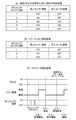
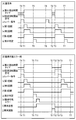
各回胴51L〜51Rは、以下に説明する各種のデータ、即ち、回胴駆動状態番号、回胴駆動パルス出力カウンタ、加速時の回胴駆動パルス切り替え回数、1図柄のステップ番号、図柄番号(通過位置用)、図柄番号(停止位置用)、回胴回転不良検出カウンタ、回胴駆動パルスデータ検索用カウンタ、回胴回転開始待機カウンタ、などを用いて管理されている。各回胴の駆動状態は、割込み(2.235ms)ごとに回胴駆動管理モジュールでチェックを行い、条件に応じて励磁データを出力する。
Each of the
上述の各種のデータのうち、回胴駆動状態番号は、0〜5の値を持っており、0は停止中又は揺れ変動中、1は回転開始待機、2は減速中、3は減速開始、4は定速中、5は加速中をそれぞれ表している。また、回胴駆動パルス出力カウンタは、励磁を切り替える割込み回数を表しており、加速時の回胴駆動パルス切り替え回数は、回胴の立ち上がりパターン(割込み回数)テーブルのオフセットを表しており、1図柄のステップ番号は、1図柄のステップ数を表している。 Among the various data described above, the rotating body drive state number has a value of 0 to 5, 0 is stopped or fluctuating, 1 is waiting for rotation start, 2 is decelerating, 3 is deceleration start, 4 indicates a constant speed, and 5 indicates an acceleration. Further, the drum drive pulse output counter indicates the number of interruptions for switching the excitation, and the number of rotation of the body drive pulse at the time of acceleration indicates the offset of the rise pattern (number of interrupts) table of the drum, and one symbol Step numbers indicate the number of steps in one symbol.
さらに、図柄番号(通過位置用)は、中段を通過している図柄番号(0〜20)を表しており、その値がFFH(Hは16進数表記であることを表す)である場合は、回胴センサ未通過であることを表している。図柄番号(停止位置用)は、中段に表示させる図柄番号(0〜20)を表しており、その値がFFHである場合は、図柄番未設定であることを表している。回胴回転不良検出カウンタは、回胴の回転不良を検出するカウンタであり、センサ通過後のステップ数/2の値を出力する。また、各回胴51L〜51Rが、回胴センサを通過すると、回胴駆動状態番号は「定速中」の「4」となる。
<遊技メダルセレクター>
<<遊技メダルセレクターの構成>>
Furthermore, the symbol number (for the passing position) indicates the symbol number (0 to 20) passing through the middle row, and when the value is FFH (H represents hexadecimal notation), This indicates that the rotation sensor has not passed. The symbol number (for the stop position) indicates the symbol number (0 to 20) to be displayed in the middle row, and when the value is FFH, it indicates that the symbol number has not been set. The rotation body rotation failure detection counter is a counter for detecting a rotation failure of the rotation body, and outputs a value of the number of steps / 2 after passing the sensor. Also, when each of the
<Game medal selector>
<< Configuration of the game medal selector >>
次に、前述の遊技メダルセレクター44について説明する。遊技メダルセレクター44は、図2中及び図3中に示すように、前面ドア部11の背面において、前面ドア部11の開放端側(図2中及び図3中の左端側)で、且つ、上下方向の略中段の部位に装着されている。さらに、遊技メダルセレクター44は、回胴表示部15の直ぐ下の部位に位置しており、前面ドア部11の前面の遊技メダル投入口21(図1参照)に投入された遊技メダルを、前面ドア部11の背後で受け入れるようになっている。
Next, the aforementioned
遊技メダルセレクター44は、図6に示すように矩形な箱状の外形を有しており、本体部101、開閉部102、ヒンジ機構部103を備えている。このうち本体部101は、前面ドア部11に固定されており、この本体部101には、図7に示すように開閉部102が、ヒンジ機構部103を介して開閉可能に装着されている。さらに、ヒンジ機構部103の配置は、前面ドア部11の背面側から見て右側の部位であり、開閉部102は、上下方向に延びるヒンジ機構部103の軸を中心として、ヒンジ機構部103に設けられたコイルばね104等の弾性復元力に抗しながら、水平方向に開放可能となっている。
The
開閉部102が閉じられた際には、本体部101との間に、1枚の遊技メダルの厚さよりも幾分大きい程度の幅のメダル通路105が形成される。すなわち、このメダル通路105は、上向きにスリット状に開口するとともに、途中の部位で屈曲及び分岐し、遊技メダルセレクター44の側方(前面ドア部11の背面から見て右側)や、下方に向かって伸びている。メダル通路105の上端は遊技メダルの入口(遊技メダル入口)106となり、この遊技メダル入口106となる開口部は、前述の遊技メダル投入口21に連通している。また、遊技メダルセレクター44の側方の出口(以下「第1出口」と称する)107は、前述の遊技メダル払出装置63に向けて遊技メダルを排出できるようになっており、下方の出口(以下「第2出口」と称する)108は、前述の遊技メダル払出口16に向けて遊技メダルを排出できるようになっている。
When the opening /
さらに、メダル通路105の途中の部位に位置する屈曲部110には、図7中に示すように、異形板状の減速部111が設けられている。この減速部111は、上端側を基端として前後方向(前面ドア部11の前後方向)に回動可能となっており、遊技メダルの通過がない場合は、メダル通路105内に弾性的に突出している。そして、遊技メダル投入口21に遊技メダルが投入され、投入された遊技メダルが屈曲部110を通りながら減速部111に接触すると、減速部111は、遊技メダルにより押されて本体部101内に没入する。さらに、減速部111は、遊技メダルが通過し、遊技メダルの押圧力から開放されると、再びメダル通路105内に突出する。そして、屈曲部110を通過する遊技メダルは、この減速部111との接触により減速されながら進路を変えて、屈曲部110の下流側へ向かう。
Further, as shown in FIG. 7, the
屈曲部110の下流側には、前述のセレクタ通路センサ46が設けられている。このセレクタ通路センサ46は、矩形板状の第1可動部112を備えており、この第1可動部112は、メダル通路105の分岐部113に、長手方向を、メダル通路105の幅方向(通過する遊技メダルの径方向)に向けた状態で配置されている。第1可動部112は、メダル通路105の上流側の一辺を基端として前後方向(前面ドア部11の前後方向)に回動可能となっており、遊技メダルの通過がない場合は、メダル通路105内に突出している。しかし、前述の減速部111を通過した遊技メダルが第1可動部112に接触すると、第1可動部112は、遊技メダルにより押されて本体部101内に没入する。そして、第1可動部112は、遊技メダルが通過して押圧力から開放されると、再びメダル通路105内に突出する。
The above-described
また、本体部101には、セレクタ通路センサ46用のマイクロセンサ(図示略)が内蔵されており、第1可動部112の没入動作の有無が、マイクロセンサにより検出されるようになっている。つまり、メダル通路105に進入して流下する遊技メダルにより、第1可動部112が押されて没入動作を行うと、この第1可動部112の動作が検出されて、マイクロセンサの出力信号が変化する。そして、前述の主制御基板61においては、このセレクタ通路センサ用のマイクロセンサからの出力を利用して、後述するような、遊技メダルの投入に係る制御(図22〜図29など)が実行される。ここで、セレクタ通路センサ46用のマイクロセンサとしては、接触式や非接触式等の種々のマイクロセンサを適用できる。また、第1可動部112は逆流した異物等が引っ掛かる(第1可動部112の下流から上流に異物が移動できない)ように構成されている。これにより、ゴト機(所謂ゴト行為に用いられる機械器具)が挿入された場合にゴト機が容易に抜けないようにすることもできる。
The
また、第1可動部112の上流側の上部には第2可動部114が設けられており、この第2可動部114も、通常はメダル通路105に弾性的に突出し、遊技メダルに押された場合には、本体部101に没入するようになっている。そして、本実施例では、第1可動部112や第2可動部114等の可動部と、セレクタ通路センサ46用のマイクロセンサ等の検出部とにより、セレクタ通路センサ46が構成されている。尚、本実施形態では、セレクタ通路センサ46を第1可動部112、及び、第2可動部114により形成しているが、これに限られるものではなく、例えば、何れか一方のみ備えていても良いし、上記のような形状でなくても良い。
In addition, a second
メダル通路105における、セレクタ通路センサ46から前述の第1出口107に向かう途中の部位には、前述の投入センサ45が設けられている。投入センサ45は、符号115で示す投入センサ1と、符号116で示す投入センサ2の2つのセンサにより構成されており、各投入センサは、本体部101に内蔵されている。なお、以下では、投入センサ1や投入センサ2に図中の符号を付して説明を行う場合には、投入センサ1(115)、投入センサ2(116)のように記載する。
The above-mentioned
投入センサ1(115)及び投入センサ2(116)は、何れも本体部101に内蔵された非接触式のマイクロセンサ(図示略)を用いたものである。さらに、投入センサ1(115)及び投入センサ2(116)は、遊技メダルの流下方向に関して、遊技メダルの直径(ここでは25mm)よりも小さい所定距離(例えば5〜10mm程度)を置いて配置されており、これらのうち投入センサ1(115)は、投入センサ2(116)よりもメダル通路105の上流側に位置している。
Each of the input sensor 1 (115) and the input sensor 2 (116) uses a non-contact type microsensor (not shown) built in the
また、投入センサ1(115)及び投入センサ2(116)に用いられるマイクロセンサとしては、受光式のものが用いられており、黒色の矩形な窓部117の斜め上方に配置された投光部118から照射された光(検出光)を、受光できるようになっている。つまり、投光部118の内部にはLED等を用いた発光器(図示略)が内蔵されており、この投光器と、投入センサ1(115)及び投入センサ2(116)との位置関係は、発光器から出力された検出光が、窓部117を透過して投入センサ1(115)及び投入センサ2(116)に入射するよう設定されている。
As the microsensor used for the input sensor 1 (115) and the input sensor 2 (116), a light-receiving microsensor is used, and a light projecting unit disposed obliquely above a black
そして、メダル通路105を流下してきた遊技メダルが検出光を遮ると、投入センサ1(115)及び投入センサ2(116)に検出光が入射しなくなり、遊技メダルが検出されて、投入センサ1(115)及び投入センサ2(116)に用いられているマイクロセンサの出力信号が変化する。そして、前述の主制御基板61においては、この投入センサ1(115)及び投入センサ2(116)からの出力を利用して、後述するような、遊技メダルの投入に係る制御(図22〜図29など)が実行される。
When the game medals flowing down the
また、本実施では、投入センサ1(115)及び投入センサ2(116)は、メダル通路105の上方寄りの部位に配置されており、例えば、複数枚の遊技メダルが連続して通過しても、遊技メダル同士の上部の間隙が、投入センサ1(115)及び投入センサ2(116)を通過するようになっている。そして、このことによって遊技メダルが1枚毎に確実に検出できるようになっている。
Further, in the present embodiment, the insertion sensor 1 (115) and the insertion sensor 2 (116) are disposed at a position closer to the upper side of the
また、図7中に示すように、開閉部102には前述のブロッカ47が設けられている。このブロッカ47は、断面L字状に成形された板状の可動ブロック部119やソレノイド(図示略)等により構成されており、可動ブロック部119には水平方向に突出した遮蔽板部120が設けられている。さらに、ブロッカ47の配置は、開閉部102が閉鎖状態となった場合に、可動ブロック部119の大部分が、セレクタ通路センサ46における第1可動部112の真下よりも、第1出口107に向かう遊技メダルを基準として、下流側に位置するよう設定されている。そして、ブロッカ47は、ソレノイド(図示略)のON/OFF駆動に伴い、可動ブロック部119を前後方向(前面ドア部11の前後方向)に進退させる。
Further, as shown in FIG. 7, the opening /
本実施例においては、ソレノイドのOFF時は、ブロッカOFF時であり、このブロッカOFF時には、可動ブロック部119が開閉部102の内部に後退し、遮蔽板部120が開閉部102の内に引き込まれた状態にある。そして、このブロッカOFF時には、下方の第2出口108が開放されており、遊技メダルが、第1出口107に向かえずに、第2出口108の側に落下して第2出口108に導かれ、受け皿17に返却される。
In this embodiment, when the solenoid is turned off, the blocker is turned off. When the blocker is turned off, the
一方、ソレノイドのON時は、ブロッカON時であり、このブロッカON時には、可動ブロック部119が、図7中に示すように、本体部101の側に前進して、遮蔽板部120がメダル通路105中に突出した状態にある。そして、このブロッカON時には、下方の第2出口108が遮蔽板部120により閉塞されており、遮蔽板部120を伝って、側方の第1出口107の側に導かれる。そして、遊技メダルが、セレクタ通路センサ46や投入センサ45を通って第1出口107に向かい、第1出口107から遊技メダル払出口16に向けて排出される。
On the other hand, when the solenoid is ON, the blocker is ON. When the blocker is ON, the
ここで、図7中に符号121で示すのは、本体部101に設けられてリジェクト機構を構成するリジェクトスイッチであり、符号122で示すのは、開閉部102の閉鎖時にリジェクトスイッチ121に対向するよう配置されたリジェクト用受け部である。そして、リジェクトスイッチ121の機能については後述する。
<<遊技メダルセレクターの機能>>
Here,
<< Function of game medal selector >>
続いて、遊技メダルセレクター44の機能について説明する。遊技メダルセレクター44には、遊技メダル選別機能、遊技メダル受付不可機能、遊技メダル検出機能がある。このうち、遊技メダル選別機能は、投入された遊技メダルが受付可能な寸法の範囲内か否かを選別する機能である。また、遊技メダル受付不可機能は、遊技状態に応じて前述のブロッカ47により、遊技メダルを受け付けずに返却する機能であり、遊技メダル検出機能は、前述の投入センサ45を通過した遊技メダルを検出する機能である。
Next, the function of the
上述の遊技メダル受付不可機能について、遊技メダルを受け付けずに返却する遊技状態としては、貯留装置(後述する)に遊技メダルが50枚貯留されていて、且つ、規定数(後述する)の遊技メダルが投入されているとき、規定数の遊技メダル投入後のスタートレバー25の操作受付からそのときの遊技である当該遊技が終了するまでの間、投入された遊技メダル及び貯留されている遊技メダルの払い戻しのとき、エラー発生の場合、設定の切り替え時及び設定の確認時、を挙げることができる。
Regarding the above-mentioned game medal unacceptable function, as a game state in which game medals are returned without being received, a storage device (to be described later) stores 50 game medals and a prescribed number (to be described later) of game medals. Is inserted, from the reception of the operation of the
受付可能な遊技メダル寸法の範囲内の遊技メダルが遊技メダル投入口21より投入されると、遊技メダルセレクター44の遊技メダル入口106からメダル通路105を通過して、遊技メダル出口(第1出口107)から遊技メダル払出装置63へ落下する。なお、遊技メダルがセレクタ通路センサ46、投入センサ45を通過すると、各センサ45、46から主制御基板61に検出信号を送る。セレクタ通路センサ46の検出信号は、遊技メダルがセレクタ通路センサ46を通過した遊技メダルの枚数を前述の遊技制御プログラムで確認するために利用される。
When a game medal within the range of receivable game medal dimensions is inserted from the game
投入センサ45の検出信号は、遊技メダルがセレクタ通路センサ46を通過した時間及び順序を前述の遊技制御プログラムで判断するのに利用される。このセレクタ通路センサ46、投入センサ45の検出信号が規定時間内、かつ、規定順序及び規定枚数の場合は、正常に遊技メダル検出が行われたこととなる。規定時間以上又は規定順序以外及び規定枚数以外の場合はエラーとなり、投入された遊技メダルは無効になる。ただし、検出信号が投入センサ1の出力信号(投入センサ1信号)のみで投入センサ2の検出信号(投入センサ2信号)による検出がない場合は、エラーにならない。
The detection signal of the
ここで、投入センサ1信号のみが検出され、投入センサ2信号が検出されない場合としては、遊技メダルが投入センサ1から逆方向に戻った場合等を挙げることができる。また、このような遊技メダル検出の具体的態様については後述する。
Here, the case where only the
変形した遊技メダルが遊技メダル投入口21から投入されると、遊技メダル入口106で滞留する。滞留した遊技メダルは、遊技メダル返却ボタン22(図1参照)を操作することにより、前述のリジェクトスイッチ121が押され、遊技メダルセレクター44の開閉部102が僅かに開き、遊技メダル払出口16から受け皿17へ返却される。受付可能な遊技メダル寸法より小さい遊技メダルが遊技メダル投入口21より投入されると、遊技メダル入口106を通過したした後、遊技メダル払出口16から受け皿17へ返却される。
When a deformed game medal is inserted from the game
また、前述の遊技メダル受付不可機能により、遊技状態に応じて前述のブロッカ47がOFFになり、可動ブロック部119がメダル通路105から退避する。そのときに受付可能な範囲内の遊技メダルが遊技メダル投入口21より投入されると、前述のように、遊技メダル入口106を通過してメダル通路105の屈曲部110に達し、更に自由落下により、第2出口108を通過して、遊技メダル払出口16から受け皿17へ返却される。
<設定変更の手順>
In addition, by the above-mentioned game medal refusal function, the above-mentioned
<Procedure for changing settings>
本実施例のスロットマシン10において、前述の設定ユニット62(図4参照)に対する設定変更のための正規な操作は、以下のように行われる。先ず、例えば遊技場店員等が、電源OFFの状態にあるスロットマシン10の前面ドア部11を開放する(図1及び図2参照)。この前面ドア部11の開放にあたっては、閉鎖状態で施錠された前面ドア部11の錠前部23(図1参照)に、前述のように、所定の鍵を挿し込んで、この鍵を開錠方向(例えば反時計回り)に回転させる。
In the
さらに、図4中に示す設定ユニット62に設けられた設定ドアを開放し、図示は省略するが、設定キーが差し込まれる設定キーシリンダへのアクセスが可能な状態とする。また、設定キーシリンダに設定キーを差し込み、設定キーをON方向(例えば時計回り方向)に回転操作(ON操作)する。そして、前述の電源スイッチ72をONして、スロットマシン10に電力供給する。このように、設定キーをON操作したまま電源スイッチ72をONすることで、後述する設定変更装置処理(図13参照)が行われる「設定変更装置作動」の状況となる。
Further, the setting door provided in the
スロットマシン10に電力供給がされると、前述の主制御基板61(図4参照)に搭載された前述の設定表示LED66に設定値が表示される。設定表示LED66には、所謂7セグ表示器が使用されている。さらに、本実施例では、設定表示LED66には、所定範囲の整数値である設定値(ここでは「1」から「6」の6つ)のうちのいずれかが表示され、この表示された設定値が透明な主基板ケース65を通して視認可能となる。
When power is supplied to the
このように設定変更装置が作動した状況において、前述の設定/リセットボタン69(図4参照)を押圧操作すると、設定値の表示が変化する。本実施例では、設定/リセットボタン69を押すごとに、設定値の表示が1段階ずつインクリメントされる。例えば、設定1(設定値が1の状態)でスロットマシン10の電源が立ち上がり、設定/リセットボタン69を1回操作すると設定2となる。その後、設定/リセットボタン69を押すごとに、設定値の表示が「2」、「3」、…と昇順に変化する。
When the setting / reset button 69 (see FIG. 4) is pressed in such a state in which the setting change device operates, the display of the set value changes. In this embodiment, each time the set /
さらに、本実施例では、遊技者にとって最も有利度合が高いのは、最高設定値である設定値6であり、設定値の値が小さくなるほど有利度合は低くなる。そして、上述の最高設定値である設定値6で設定/リセットボタン69を1回操作すると、最低設定値である設定1となる。さらに、設定表示LED66に表示された値が、選択目的としている設定値になっている状況で、遊技店員等が前述のスタートレバー25(図1参照)を操作してスタートスイッチ(図示略)をONすることにより、設定値が確定する。
Furthermore, in the present embodiment, the highest degree of advantage for the player is the setting
なお、前述のように設定/リセットボタン69を押した際における、設定値の表示に係る変化の態様は、設定値の表示が1段階ずつインクリメントされるものに限らず、例えば、設定値の表示が1段階ずつデクリメントされて、降順に変化するものであってもよい。さらに、後述する設定変更装置処理(図13参照)により変更可能な設定値の範囲は、「1」〜「6」の6段階に限らず、例えば、「1」〜「4」の4段階などであってもよい。
As described above, when the setting /
続いて、設定キーをOFF方向(例えば反時計回り方向)に回転操作(OFF操作)し、設定ユニット62に設けられた設定ドアを閉じて、正規な設定変更の操作が完了し、遊技が可能な状態(通常状態)となる。
Subsequently, the setting key is turned in the OFF direction (for example, counterclockwise direction) (OFF operation), the setting door provided in the
ここで、前述の「設定変更装置作動」の状況となった後、設定/リセットボタン69の操作が有効になった後の状況を「設定値変更可能中」の状況であると称することができる。この「設定値変更可能中」は、設定/リセットボタン69の操作による設定値の変更(選択)が可能な状況である。
Here, after the above-described “setting change device operation” status, the status after the operation of the setting /
また、「設定値変更可能中」の後、スタートレバー25の操作(レバー操作)により設定値を確定させた状態を「設定値確定」の状況と称することができる。そして、設定値の変更がされる場合には、「設定値変更可能中」で、前述のように設定/リセットボタン69が操作され、目的の設定値に達した状態でスタートレバー25が操作されて「設定値確定」の状況になる。そして、「設定値確定」の状況では、設定/リセットボタン69を操作しても、設定値の表示は変化しない。
Further, a state in which the set value is determined by the operation of the start lever 25 (lever operation) after “the set value is being changed” can be referred to as a “set value determined” state. When the set value is to be changed, the setting /
また、上述の「設定値確定」の後、設定キーがOFFされるのを待っている状態を、「設定値決定待ち」の状況と称することができる。この「設定値決定待ち」の状況においても、設定/リセットボタン69の操作により設定値を変化させることは不可能である。さらに、本実施例では、設定変更作業における状態を第1状態と第2状態とに分けることが可能である。そして、設定キーがONされた状況で電源投入がされると、設定変更に係る第1状態に移行し、その後にスタートレバー25が操作されると、第1状態から第2状態へ移行する。さらに、この設定変更に係る第2状態において設定キーがOFFされると、第2状態が終了する。
<遊技を行う手順及び遊技メダル投入時の処理>
Further, a state of waiting for the setting key to be turned off after the above-mentioned “setting value determination” can be referred to as a “waiting for setting value determination” state. Even in the "waiting for setting value determination" situation, it is impossible to change the setting value by operating the setting /
<Procedure for performing a game and processing when a game medal is inserted>
次に、遊技を行う手順及び遊技メダル投入時の処理について説明する。遊技メダル投入時の処理においては、遊技メダルセレクター44(図6参照)が遊技メダル受付状態(遊技メダル通過可能状態)になっている場合は、遊技メダル投入口21(図1参照)より遊技メダルを投入することができる。ここで、「遊技メダルの投入」とは、「賭数の設定」と同義であり、「賭数の設定」は、「ベットする」と同義である。遊技メダルを投入すると、投入枚数に応じて前述の投入枚数表示LEDが点灯し、規定数の遊技メダルを投入することによりスタートレバー25が有効に操作可能となる。そして、スタートレバー25が有効に操作可能となることにより、スタートレバー25の操作に基づく役抽せん、フリーズ抽選(後述するフリーズ演出のための抽選)、回胴駆動状態の更新等の処理が実行できるようになる。なお、遊技メダルは遊技媒体として用いられているものであり、遊技媒体としては、遊技メダルに限らず、遊技球や電子データなどを用いることも可能である。
Next, a procedure for performing a game and a process for inserting a game medal will be described. In the processing at the time of inserting the game medal, when the game medal selector 44 (see FIG. 6) is in the game medal receiving state (the state in which the game medal can pass), the game medal is inserted from the game medal slot 21 (see FIG. 1). Can be input. Here, "insertion of a game medal" is synonymous with "setting of the number of bets", and "setting of the number of bets" is synonymous with "betting". When a game medal is inserted, the above-mentioned insertion number display LED is turned on in accordance with the insertion number, and the
なお、遊技状態ごとの最大規定数を超えて投入すると、以降の遊技メダルは貯留装置に貯留される。貯留装置は、スロットマシン10の制御上、遊技メダルを所定枚数(ここでは50枚)まで貯留可能とする機能を果たすものである。ただし、貯留されている遊技メダルの枚数が最大枚数である50枚を超える場合は、遊技メダルセレクター44が遊技メダル返却状態になり、遊技メダル投入口21より投入された遊技メダルは、遊技メダル払出口16(図1参照)から受け皿17へ返却される。貯留装置は「クレジット」とも呼ばれ、具体的には遊技メダルを電気的に記憶(RWMに記憶)するものを指す。
In addition, when the game medal is inserted more than the maximum specified number for each game state, subsequent game medals are stored in the storage device. The storage device has a function of storing a predetermined number of game medals (here, 50) under the control of the
回胴回転については、規定数の遊技メダルを投入後、スタートレバー25を操作し、回胴回転装置54を作動させることにより回胴を回転させることができる。ただし、清算ボタン、停止ボタン24L〜24R、1枚投入ボタン又は3枚投入ボタンのいずれかを操作している状態では、スタートレバー25を操作しても回胴51L〜51Rを回転させることはできない。
Regarding the rotation of the torso, the player can rotate the torso by operating the
スタートレバー25を操作すると、回胴51L〜51Rが加速回転を始め、所定の回転数に(ここでは79.90回転/分)に達すると定速状態となる。スタートレバー25が操作されると、遊技メダルセレクター44は遊技メダル返却状態となる。前回の遊技で回胴51L〜51Rが回転し始めてから最小遊技時間(最短遊技時間)である所定時間(ここでは4.1秒)が経過していない場合に、スタートレバー25を操作しても、回胴51L〜51Rは回転しない。前回の遊技で回胴が回転し始めてから4.1秒経過に回胴51L〜51Rが回転を始める。ただし、後述するような遊技演出(フリーズ演出など)による遊技待機中の場合は、遊技待機終了後に回胴が回転を始めるように制御することも可能である。ここで、本実施例のスロットマシン10においては、最小遊技時間の管理に関して、状況に応じた種々の態様で管理が行われているが、それらについては後述する。
When the
回胴51L〜51Rが回転を始め、回胴51L〜51Rのすべてが正常回転(ここでは定速かつ脱調していない状態の回転)していることを検知すると、停止ボタン24L〜24Rの操作が受付可能な状態になる。ただし、回胴51L〜51Rのすべてが正常回転していることが検出されない場合は、正常回転するまで停止ボタン24L〜24Rの操作が受付可能な状態にならない。スタートレバー25を操作した後から、回胴51L〜51Rがすべて停止するまでの間に遊技メダル投入口21より投入された遊技メダルは、遊技メダル払出口16から受け皿17へ返却される。
When it is detected that the
回胴回転の停止においては、回転している回胴51L〜51Rを任意に選択し、それに対応した停止ボタン24L〜24Rを操作することにより、回胴51L〜51Rを停止させることができる。ただし、清算ボタン、スタートレバー25、すでに停止している回胴に対応する停止ボタン、1枚投入ボタン又は3枚投入ボタンのいずれかを操作している状態では、停止ボタンを操作しても回転中の回胴を停止させることはできない。なお、これらの主制御基板61で管理されるボタン(メイン系ボタン)に関し、組合せによっては一部のボタンが操作可能(操作が有効)となるようにすることも可能である。そして、操作できる(操作が有効になる)ボタンやスイッチと、操作できない(操作が無効になる)ボタンやスイッチとの組合せは任意に決めることができる。例えば、いずれか1つの停止ボタンの操作中は他の停止ボタンの操作ができないが、スタートレバー25の操作中(操作後)であればいずれも停止ボタンを操作できる、などといった組合せ態様を例示することができる。
In stopping the rotation of the rotating drum, the
停止ボタン24L〜24Rが操作されると、それに対応した回胴が所定時間(ここでは190ms)以内に停止する。残りの回転しているいずれかの回胴も同様に、任意に選択した回胴に対応した停止ボタンを操作して停止させる。停止ボタンを操作し続けた場合は、残りの停止ボタンを操作しても、それに対応した回胴は停止しない。スタートレバー25を操作した後、停止ボタン24L〜24Rを操作しない限り回転中の回胴51L〜51Rは停止しない。但し、フリーズ演出中の場合には、停止ボタン24L〜24Rの操作を介さずに回転中の回胴を停止させるように構成することも可能である。
When the
図柄の組合せの表示判定においては、回胴51L〜51Rがすべて停止したとき、投入に係る規定数に応じた有効ライン上で入賞又は役物作動に係る図柄の組合せの表示判定を行う。ただし、3番目の停止である第3停止時にスタートレバー25又はいずれかの停止ボタン24L〜24Rを操作し続けた場合は、操作解除後に、規定数に応じた有効ライン上で入賞又は作動に係る図柄の組合せの表示判定を行う。なお、「図柄組合せの表示判定」や「表示判定」は、メインCPU81が、停止した図柄を検出して停止図柄が何であるかを直接的に判定するといったようなこと(所謂出目をみること)ではなく、例えば、回胴51L〜51Rの制御に異常が生じなかったか否かを判定し、異常がなければ図柄表示が適正に行われている旨の判定を行い、正常に図柄停止が行われたものとして以降の処理を進める、といったようなことを意味している。ここで、図示は省略するが、本実施例のスロットマシン10において投入可能な規定数は、役物作動時の遊技においては2枚、それ以外の遊技においては3枚であり、有効ラインは、回胴表示部15(図1参照)の上段、中段、及び、下段の3ラインである。なお、これに限らず、有効ラインを、中段のみの1ラインとしたり、斜め右上がり、及び、斜め左上りを加えた5ラインとしたものなどの採用も可能である。そして、規定数に応じた有効ライン上に、入賞に係る図柄の組合せが表示された場合は、該当する場合の制御を実行し、役物作動又は役物連続作動装置に係る図柄の組合せが表示された場合は、役物作動又は役物連続作動装置に係る図柄の組合せが表示された場合の制御が実行される。
In the display determination of the symbol combination, when all of the turning
入賞に係る図柄の組合せが表示された場合、規定数ごとの当該入賞に係る図柄の組合せに対応した枚数分の遊技メダルが払い出され、遊技者によって獲得される。なお、獲得される遊技メダルは、前述の貯留装置に貯留される。ただし、貯留されている遊技メダルの枚数が50枚を超える場合は、超える獲得枚数分を遊技メダル払出口16から受け皿17へ払い出す。遊技メダルの獲得中に遊技メダル投入口21より投入された遊技メダルは、遊技メダル払出口16から受け皿17へ返却される。規定数ごとの当該入賞に係る図柄の組合せに対応した枚数分の遊技メダルがすべて獲得されると、遊技メダルセレクター44は、所定の条件を満たした場合には遊技メダル受付状態になる。そして、前述の遊技メダル投入時の処理が実行される。本実施例においては、1回の入賞により獲得することができる遊技メダルの枚数の上限は15枚を超えることはないようになっている。
When the combination of the symbols related to the winning is displayed, the game medals of the number corresponding to the combination of the symbols related to the winning for each prescribed number are paid out and acquired by the player. The game medals to be obtained are stored in the storage device described above. However, when the number of stored game medals exceeds 50, the number of acquired medals is paid out from the game
役物の作動に係る図柄の組合せが表示された場合においては、該当する役物に応じた処理が実行される。本実施例では、役物として(抽せんされる役として)、所謂、普通役物、第一種特別電動役物、第二種特別電動役物、第一種特別電動役物に係る役物連続作動装置、の各々が作動することとなる図柄の組合せに該当するものは設けられていないが、再遊技が作動することとなる図柄の組合せ、及び、第一種特別役物に係る役物連続作動装置が作動することとなる図柄の組合せは設けられている。そして、これらに該当する図柄の組合せが表示された場合は、該当する処理を実行する。 When a combination of symbols related to the operation of the accessory is displayed, a process corresponding to the corresponding accessory is executed. In this embodiment, as a character (as a role to be drawn), a so-called ordinary character, a first-class special motorized character, a second-class special motorized character, and a consecutive character related to the first-class special motorized character There is no pattern corresponding to the combination of symbols in which each of the actuation devices will be activated, but the combination of symbols in which the replay will be activated, and the continuation of the official goods relating to the first-class special character There is a combination of symbols that will actuate the actuator. Then, when a combination of symbols corresponding to these is displayed, the corresponding process is executed.
一方、入賞及び作動に係る図柄が表示されなかった場合においては、遊技メダルセレクター44は遊技メダル受付状態になる。そして、前述の遊技メダル投入時の処理が実行される。
On the other hand, when the symbols related to winning and operation are not displayed, the
続いて、規定数ごとの入賞に係る図柄の組合せ及び当該図柄の組合せが表示された場合に獲得することができる遊技メダルの枚数について説明する。入賞に係る図柄の組合せ、及び、対応して獲得することができる遊技メダルの枚数は、規定数ごとにあらかじめ定められている。入賞に係る図柄の組合せを表示することなく、遊技メダルを獲得することはできないようになっている。また、入賞に係る条件装置が作動することなく、入賞に係る図柄の組合せが表示されることはないようになっている。 Next, a description will be given of a combination of symbols related to winning for each specified number and the number of game medals that can be obtained when the combination of symbols is displayed. The combination of symbols related to winning and the number of game medals that can be obtained correspondingly are determined in advance for each prescribed number. A game medal cannot be obtained without displaying a combination of symbols related to winning. Further, the combination of the symbols related to the winning is not displayed without the condition device related to the winning being operated.
そして、役物及び役物連続作動装置未作動時における入賞に係る図柄の組合せ及び遊技メダル獲得枚数は、規定数3枚時についてのみが定められており、入賞に係る図柄の組合せ(1図柄又は2図柄のみ規定されたものを含む)の数としては、獲得枚数毎に所定数が規定されている。さらに、第一種特別役物作動時における入賞に係る図柄の組合せ及び遊技メダル獲得枚数は、規定数2枚時についてのみが定められており、入賞に係る図柄の組合せ(1図柄又は2図柄のみ規定されたものを含む)の数としては、獲得枚数毎に所定数が規定されている。なお、これらの入賞に係る図柄の組合せや、獲得枚数との具体的な関係については後述する。 Then, the combination of symbols related to winning and the number of game medals obtained when the accessory and the continuous actuation device of the accessory are not operated are determined only when the specified number is three, and the combination of symbols related to winning (one symbol or A predetermined number is defined for each acquired number as the number of (including the case where only two symbols are specified). Furthermore, the combination of symbols related to winning and the number of game medals obtained when the first-class special role is activated are determined only when the specified number is two, and the combination of symbols related to winning (only one symbol or two symbols) As a number, a predetermined number is defined for each acquired number. The combination of the symbols related to these winnings and the specific relationship with the number of winnings will be described later.
続いて、規定数ごとの作動に係る図柄の組合せについて説明する。再遊技、役物及び役物連続作動装置の作動に係る図柄の組合せは、規定数ごとにあらかじめ定められている。再遊技、役物及び役物連続作動装置等の作動に係る条件装置が作動せず(未作動時)に、再遊技、役物及び役物連続作動装置の作動に係る図柄の組合せが表示されることはないようになっている。 Next, a description will be given of a combination of symbols related to the operation for each specified number. The combination of symbols related to the replay, the accessory, and the operation of the accessory continuous operation device is determined in advance for each specified number. A condition combination relating to the operation of the replay, the role of the character and the continuous operation of the character is not activated (when not operated), and the combination of the symbols relating to the operation of the replay, the role of the character and the continuous operation of the character is displayed. It is not going to be.
そして、役物及び役物連続作動装置未作動時における作動に係る図柄の組合せ及び作動名称は、規定数3枚時についてのみが定められており、作動に係る図柄の組合せ(1図柄のみ又は2図柄のみ規定されたものを含む)の数としては、本実施例では8種類が設けられている。なお、これらの作動名称と図柄の組合せとの具体的な関係については後述する。そして、作動に係る図柄の組合せが表示された場合には、その後に作動名称に応じた遊技制御が実行されることになる。 Combinations of symbols and operation names related to operation when the accessory and the accessory continuous operation device are not operated are defined only for the prescribed number of three, and a combination of symbols related to the operation (only one symbol or 2 symbols) In this embodiment, eight types are provided as the number of symbols (including only the symbols defined). The specific relationship between these operation names and symbol combinations will be described later. Then, when the combination of symbols related to the operation is displayed, the game control corresponding to the operation name is executed thereafter.
続いて、再遊技を行うことができることとなる図柄の組合せ、当該図柄の組合せが表示されたときの効果及び当該図柄の組合せが表示された場合の処理について説明する。回胴51L〜51Rがすべて停止したときに、有効ライン上に表示した図柄の組合せが再遊技に係る図柄の組合せであれば、再遊技が作動する。また、本実施例のスロットマシン10には、再遊技に係る条件装置が作動する確率が変動する遊技が設けられている。
Next, a description will be given of a combination of symbols that can be played again, an effect when the combination of symbols is displayed, and a process when the combination of symbols is displayed. When all of the
再遊技に係る条件装置の作動する確率の変動契機は、第一種特別役物に係る役物連続作動装置の作動に係る条件装置が作動したとき、第一種特別役物に係る役物連続作動装置が作動することとなる図柄の組合せが有効ライン上に表示されたとき、及び、第一種特別役物に係る役物連続作動装置の作動が終了したとき、である。再遊技を行うことができることとなる図柄の組合せが表示された場合の処理としては、自動的に前回の遊技と同数の遊技メダルが投入された状態となり、スタートレバー25が操作可能になる。再遊技に係る図柄の組合せが表示されてから遊技メダル投入口21より投入された遊技メダルは、所定の条件を満たした場合には貯留装置に貯留される。そして、その後は、前述した通常時(ここでは再遊技以外の場合)と同様に、回胴回転についての制御、回胴回転の停止についての制御、及び、回胴の組合せの表示判定についての制御が実行される。
The probability of the probability that the condition device relating to the replay will be activated is changed when the condition device relating to the operation of the continuous actor device relating to the special
続いて、第一種特別役物について説明する。第一種特別役物に係る役物連続作動装置が作動すると、同時に第一種特別役物に係る役物連続作動装置作動時の第一種特別役物が作動する。また、第一種特別役物に係る役物連続作動装置の作動時において、第一種特別役物の作動が終了すると、ただちに第一種特別役物に係る役物連続作動装置作動時の第一種特別役物が再度動作する。以上のように第一種特別役物が作動すると、前述した通常時(ここでは第一種特別役物に係る遊技以外の場合)と同様に、遊技メダル投入時の処理、及び、回胴回転についての制御による遊技を行う。 Next, the first-class special accessory will be described. When the continuous actuating device for the first special special item is operated, the first special special item at the same time as the continuous actuating device for the first special special item is operated. In addition, during the operation of the continuous actuating device for the first special special feature, if the operation of the first special special feature is completed, the operation of the continuous actuating device for the first special specialty immediately ends. A special character operates again. When the first-class special accessory is activated as described above, the processing at the time of inserting the game medal and the rotation of the spine are performed in the same manner as in the above-described normal state (here, in the case other than the game relating to the first-class special accessory). The game is controlled by the control.
さらに、回胴回転の停止の制御に際しては、遊技者が、回転している回胴を任意に選択し、それに対応した停止ボタンを操作することにより、回胴を停止させることができる。ただし、清算ボタン、スタートレバー、すでに停止している回胴に対応する停止ボタン、1枚投入ボタン又は3枚投入ボタンのいずれかを操作している状態では、停止ボタンを操作しても回転中の回胴を停止させることはできない。第1回胴51L〜第3回胴51Rに対応した停止ボタン24L、24C、24Rを操作した場合、対応する回胴の回転は、前述の場合と同様に、所定時間(ここでは190ms)以内に停止する。
Furthermore, in controlling the rotation of the rotating drum, the player can arbitrarily select the rotating rotating drum and operate the corresponding stop button to stop the rotating drum. However, if any of the clearing button, start lever, stop button corresponding to the already stopped torso, one-sheet insertion button, or three-sheet insertion button is operated, even if the stop button is operated, it is rotating. Can not stop the torso. When the
いずれかの停止ボタンを操作し続けた場合は、残りの停止ボタンを操作してもそれに対応した回胴は停止しないようになっている。スタートレバー25を操作した後は、停止ボタンを操作しない限り回転中の回胴は停止しない。そして、図柄の組合せの表示判定については、前述した通常時と同様に、回胴の組合せの表示判定についての制御が実行される。尚、本実施形態では、停止ボタンの操作を有効的に受け付けた後に、次の停止ボタンが有効的に受け付けられるまでに約200msの待機時間(回胴停止受付待機時間ともいう。)を設けている。つまり、全リール(51L〜51R)が回転している場合に、例えば左停止ボタン(第1停止ボタン24L)が操作された後は200ms後に中又は右の停止ボタン(第2停止ボタン24C又は第3停止ボタン24R)が受付可能となる。
When any one of the stop buttons is continuously operated, even if the remaining stop buttons are operated, the corresponding torso is not stopped. After operating the
第一種特別役物の作動終了については、第一種特別役物は、規定の回数の遊技が終了したこと、又は、入賞回数が規定数に達したことを作動終了条件としており、これらの作動終了条件のうちの少なくとも一方が成立すると、その作動を終了するようになっている。 Regarding the end of the operation of the first-class special bonus, the first-class special bonus is based on the condition that the specified number of games has been completed or the number of winnings has reached the specified number. When at least one of the operation termination conditions is satisfied, the operation is terminated.
続いて、第一種特別役物に係る役物連続作動装置について説明する。第一種特別役物に係る役物連続作動装置未作動時の遊技において、回胴がすべて停止したときに、有効ライン上に表示した図柄の組合せが第一種特別役物に係る役物連続作動装置の作動に係る図柄の組合せであれば、前述の第一種特別役物に係る遊技を実行する。第一種特別役物に係る役物連続作動装置の作動終了の契機は、遊技メダル獲得枚数が所定枚数(例えば465枚)を超えた場合である。そして、その後は、前述した通常時と同様に、遊技メダル投入時の処理に移る場合がある。
<遊技演出>
Next, the accessory continuous operation device according to the first kind special accessory will be described. In the game in which all the torso cylinders are stopped in the game when the continuous actuating device related to the special
<Game production>
前述の遊技演出としては、代表的にはフリーズ演出がある。このフリーズ演出は、遊技の進行を所定期間一時停止状態にして遅延させるものであり、この意味で遅延演出ということもできる。さらに、フリーズ演出に関しては以下のように分類して捉えることができる。すなわち、フリーズ演出は、遊技者がフリーズ演出の実行を容易に認識できるものと、認識できない(又は認識し難い)ものとに分けることができる。このうち、フリーズ演出の実行を容易に認識できるものには、スタートレバー25の操作に回胴を応答させないものや、応答はさせるが通常の遊技時の回胴の動作態様とは異なる態様で回胴を作動させるリール演出(回胴演出)を行うもの、などがある。スタートレバー25の操作に回胴を応答させないものとしては、スタートレバー25を操作しても回胴が作動開始しないものや、作動開始までに所定期間(例えば10秒間)を要するもの、などがある。
<主制御基板における主要動作>
As the above-mentioned game production, there is typically a freeze production. This freeze effect is to delay the progress of the game by suspending it for a predetermined period, and in this sense, it can also be called a delayed effect. Furthermore, freeze effects can be classified and grasped as follows. In other words, the freeze effect can be divided into one in which the player can easily recognize the execution of the freeze effect and one in which the player cannot recognize (or hardly recognize) the execution of the freeze effect. Among them, those that can easily recognize the execution of the freeze effect include those that do not respond to the operation of the
<Main operation on main control board>
次に、本実施例に係るスロットマシン10の主制御手段として機能する主制御基板61について、主要動作を図11以降の図面に基づき説明する。先ず、主制御基板61は、前述のメインCPU81が、例えばメインCPU81の内蔵ROMや、主制御基板61上に実装された外付けのROM(メインROM82)に記憶された前述の第1制御プログラムや第2制御プログラム(後述する)に基づき、メインCPU81の内蔵RWMや、主制御基板61上に実装された外付けのRWM(メインRWM83)等を用いて、乱数抽せんや、各種機器の制御などを実行するものである。
Next, main operations of the
さらに、主制御基板61は、画像等を用いた演出に係る制御を行うサブ制御基板31に対し、遊技状態や抽せん結果に応じたコマンド(「メインコマンド」、「サブ制御コマンド」、「サブメインコマンド」などともいう)を送信する機能を有している。そして、主制御基板61に対しては、前述の電源ユニット64から電力が供給される。なお、ここでは図示の便宜上、外付けのROMやRWMに符号82、83を付して説明を行ったが、以下では、特に記載がない場合は、ROM82やRWM83は、メインCPU81の内蔵のものと外付けのものの総称として用いる。
Further, the
ここで、前述の乱数抽せんとしては、先述した再遊技、役物、役物連続作動装置等の役抽せんや、フリーズ抽選等の演出抽選、AT(アシストタイム)等の実行に関するAT抽選などを例示できる。また、主制御手段は、主制御基板61のほか、メインCPU81や、メインCPU81と協働して主制御基板61の各種機能を実現するメインROM82やRWM83等の周辺機器等を包含する概念のものである。さらに、場合に応じて「抽せん」と「抽選」の用語を使い分けているが、これらは同じ意味を有する用語である。
<第1制御と第2制御との関係>
Here, as the above-mentioned random number lottery, the lottery lottery of the replaying game, the role-playing device, the role-acting device, the effect lottery such as the freeze lottery, the AT lottery relating to the execution of the AT (assist time), etc. are exemplified. it can. The main control means has a concept including a
<Relationship between first control and second control>
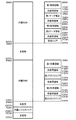
次に、前述した第1制御と第1制御プログラム、及び、第2制御と第2制御プログラムについて説明する。図11は、メインCPU81のメモリマップの一例を示している。図11中のメモリマップは、「0000H」から「FFFFH」までのアドレス空間を示している。このうち、内蔵ROMには「0000H」から「2FFFH」までの空間が割り当てられており、内蔵RWMには「F000H」から「F3FFH」までの空間が割り当てられている。
Next, the first control and the first control program and the second control and the second control program described above will be described. FIG. 11 shows an example of a memory map of the
さらに、「FE00H」から「FEBFH」までの空間には、メインCPU81内の各回路に内蔵されているレジスタのための、レジスタ領域(内蔵レジスタエリア)が割り当てられている。そして、メインCPU81に、これらの番地に対してアクセスする命令を実行させることにより、対応するハードウェアに対するアクセスを実行させることが可能となっている。
Further, in a space from “FE00H” to “FEBFH”, a register area (built-in register area) for a register built in each circuit in the
前述の内蔵ROM(0000H〜2FFFH)の構成は、第1ROM領域と第2ROM領域に分けることができる。これらのうち、第1ROM領域は、主として遊技の進行を制御する領域となっている。また、第2ROM領域は、主としてエラー関連等の、遊技の正常な進行とは異なる状況に係る処理を制御する領域となっている。 The configuration of the aforementioned built-in ROM (0000H to 2FFFH) can be divided into a first ROM area and a second ROM area. Of these, the first ROM area is an area mainly for controlling the progress of the game. Further, the second ROM area is an area for mainly controlling processing related to a situation different from the normal progress of the game, such as an error-related situation.
第1ROM領域は、図中の右側に示す第1制御領域(「0000H」から「11FAH」まで)と第1データ領域(「1200H」から「1D9EH」まで)を有するものとなっている。また、第2ROM領域は、同じく図中の右側に示す第2制御領域(「2000H」から「22E4H」まで)と第2データ領域(「22E5H」から「2346H」まで)を有するものとなっている。 The first ROM area has a first control area (from "0000H" to "11FAH") and a first data area (from "1200H" to "1D9EH") shown on the right side in the drawing. The second ROM area has a second control area (from "2000H" to "22E4H") and a second data area (from "22E5H" to "2346H") also shown on the right side in the figure. .
さらに、第2制御領域は、前述した第1データ領域との間に未使用領域(1D9FH〜1FFFH)を介在させている。また、第2制御領域の最終アドレス(22E4H)と第2データ領域の先頭アドレス(22E5H)は連続しており、第2データ領域の最終アドレス(2346H)の後には、未使用領域(2347H〜2FBFH)と、管理エリア(2FC0H〜2FFFH)が設けられている。 Further, the second control area has an unused area (1D9FH to 1FFFH) interposed between the second control area and the first data area. The last address (22E4H) of the second control area and the start address (22E5H) of the second data area are continuous. After the last address (2346H) of the second data area, the unused area (2347H to 2FBBFH) is used. ) And management areas (2FC0H to 2FFFH).
本実施例においては、第1ROM領域は、第2ROM領域よりも容量が大きくなるように構成されている。例えば、第1ROM領域に関して、未使用領域を含めず、第1制御領域と第1データ領域のみからなるものとし、第2ROM領域に関しても、同様に未使用領域を含めず、第2制御領域と第2データ領域のみからなるものとした場合にも、この関係が成立するようになっている。なお、図11中に示すメモリマップは一例であり、各領域のバイト数や未使用領域の有無については、種々に変更が可能である。 In the present embodiment, the first ROM area is configured to have a larger capacity than the second ROM area. For example, regarding the first ROM area, the unused area is not included, and only the first control area and the first data area are included. Similarly, the unused area is not included in the second ROM area. This relationship is established even when the data area is composed of only two data areas. Note that the memory map shown in FIG. 11 is an example, and the number of bytes in each area and the presence or absence of an unused area can be variously changed.
前述の内蔵RWM(F000H〜F3FFH)の構成は、第1RWM領域と第2RWM領域に分けることができる。これらのうち、第1RWM領域は、主に遊技の進行に基づく情報(遊技データ)を必要に応じて書き込んで格納したり、書き込んだ情報を更に更新したりする領域(使用領域と称することがある)となっている。また、第2RWM領域は、主にエラー関連等の遊技の正常な進行とは異なる処理に基づく情報を格納する領域(使用領域外と称することがある)となっている。なお、第1RWM領域は、第1制御において用いられるRWM領域であり、第2RWM領域は第2制御において用いられるRWM領域であるということもいえる。 The configuration of the aforementioned built-in RWM (F000H to F3FFH) can be divided into a first RWM area and a second RWM area. Of these, the first RWM area is an area (hereinafter referred to as a used area) in which information (game data) based mainly on the progress of the game is written and stored as needed, or the written information is further updated. ). In addition, the second RWM area is an area for storing information based on processing that is different from the normal progress of the game, such as error-related processing (may be referred to as an out-of-use area). It can be said that the first RWM area is an RWM area used in the first control, and the second RWM area is an RWM area used in the second control.
第1RWM領域は、図中の右側に示す第1作業領域(「F000H」から「F14AH」まで)と第1スタックエリア(「F1D7H」から「F1FFH」まで)を有するものとなっている。また、第2RWM領域は、同じく図中の右側に示す第2作業領域(「F210H」から「F21EH」まで)と第2スタックエリア(「F3F3H」から「F3FFH」まで)を有するものとなっている。ここで、第2RWM領域を、F200Hから始まるように定めることも可能である。 The first RWM area has a first work area (from “F000H” to “F14AH”) and a first stack area (from “F1D7H” to “F1FFH”) shown on the right side in the drawing. Further, the second RWM area has a second work area (from “F210H” to “F21EH”) and a second stack area (from “F3F3H” to “F3FFH”) also shown on the right side of the drawing. . Here, it is also possible to determine the second RWM area so as to start from F200H.
また、第1スタックエリアは、第1制御に係るプログラムが内部的にデータを保存しておく必要がある場合に使用される領域となっており、第2スタックエリアは、第2制御に係るプログラムが内部的にデータを保存しておく必要がある場合に使用される領域となっている。そして、第1スタックエリアや第2スタックエリアは、例えば、サブルーチンへの移行時に記憶される戻り番地の情報(戻り番地データ)が、遊技の状況に応じて随時書き込まれるようになっている。なお、図11中に示すメモリマップは一例であり、各領域のバイト数等については、種々に変更が可能である。 The first stack area is used when a program related to the first control needs to store data internally, and the second stack area is used for a program related to the second control. Is an area used when data needs to be stored internally. In the first stack area and the second stack area, for example, return address information (return address data) stored at the time of transition to the subroutine is written at any time according to the situation of the game. Note that the memory map shown in FIG. 11 is an example, and the number of bytes in each area and the like can be variously changed.
第1スタックエリアと第2作業領域の間には、所定の大きさの未使用領域(F200H〜F20FHの16バイト)が設けられている。この未使用領域は必須のものとすることが考えられる。さらに、第1作業領域と第1スタックエリアの間、及び、第2作業領域と第2スタックエリアの間にも、所定の大きさの未使用領域(F14BH〜F1D6H、F21FH〜F3F2H)が設けられている。これらの未使用領域については、必須のものとはしないことが考えられる。 An unused area (16 bytes of F200H to F20FH) having a predetermined size is provided between the first stack area and the second work area. This unused area may be required. Further, unused areas (F14BH to F1D6H, F21FH to F3F2H) having a predetermined size are provided between the first work area and the first stack area and between the second work area and the second stack area. ing. It is conceivable that these unused areas are not required.
第1RWM領域は、第2RWM領域よりも容量が大きいものとなっている。また、本実施例では、第1作業領域と第1スタックエリアの組を第1RWM領域としており、第2作業領域と第2スタックエリアの組を第2RWM領域としている。しかし、これに限定されず、第1スタックエリアが第1RWM領域に含まれず、第2スタックエリアが第2RWM領域に含まれないといったような構成を採用することも可能である。この場合は、例えば、「F000H」から「F14AH」までの空間には第1RWM領域が割り当てられ、「F210H」から「F21EH」までの空間には第2RWM領域が割り当てられたものとすることが可能である。 The first RWM area has a larger capacity than the second RWM area. In the present embodiment, a set of the first work area and the first stack area is a first RWM area, and a set of the second work area and the second stack area is a second RWM area. However, the present invention is not limited to this, and it is also possible to adopt a configuration in which the first stack area is not included in the first RWM area, and the second stack area is not included in the second RWM area. In this case, for example, the first RWM area may be allocated to the space from “F000H” to “F14AH”, and the second RWM area may be allocated to the space from “F210H” to “F21EH”. It is.
ここで、主制御基板が搭載するROMに関しては、不正行為によって改造されたプログラム等を書き込まれることを防止するため、未使用の領域(充填されていない領域)を設けないよう構成することが好適である。このようにするために、例えば、未使用領域を全て0によって充填し、使用している領域を若い(数値の小さい)番地に詰めて書き込む、等のことが考えられる。本実施例における、未使用領域は、すべてのビットが「0」となっており、当該未使用領域以外の領域は、いずれかのビットが「1」となっている(「0」ではなくなっている)。
<RWMの初期化の契機と範囲>
Here, with respect to the ROM mounted on the main control board, it is preferable that an unused area (unfilled area) is not provided in order to prevent a program or the like modified by an illegal act from being written. It is. To do this, for example, it is conceivable to fill all unused areas with zeros and fill the used areas with younger addresses (small numerical values) and write them. In the present embodiment, all bits of the unused area are “0”, and in the area other than the unused area, any one of the bits is “1” (they are no longer “0”). There).
<Trigger and scope of RWM initialization>
次に、第1RWM領域及び第2RWM領域の初期化の契機と範囲について説明する。まず、第1RWM領域の初期化の契機と範囲については、本実施例では電断復帰の状況に応じて、以下の(1)〜(3)のように定められている。
(1)設定変更装置作動時において、電源断復帰が正常に実行できない場合
第1RWM領域(「F000H」〜「F1FFH」)にデータ0をセットする。
(2)設定変更装置作動時において、電源断復帰が正常に実行できない場合以外の場合
第1RWM領域(「F000H」〜「F1FFH」)のうち、設定値データ、割込みカウンタ、内蔵乱数加工用乱数、ソフト乱数初期値及びRT状態番号、を除く範囲(「F008H」〜「F1FFH」)にデータ0をセットする。
(3)電源断復帰時である場合
第1RWM領域(「F000H」〜「F1FFH」)の作業領域(第1作業領域)及び第1スタックエリアの最大使用量を除く領域(「F14BH」〜「F1D6H」)にデータ0をセットする。
Next, the triggers and ranges of the initialization of the first RWM area and the second RWM area will be described. First, the trigger and range of the initialization of the first RWM area are determined in the present embodiment as the following (1) to (3) according to the state of the power interruption recovery.
(1) When the power-off recovery cannot be executed normally when the setting change device is operating
(2) When the setting change device is operating, except when the power-off recovery cannot be executed normally. In the first RWM area (“F000H” to “F1FFH”), set value data, an interrupt counter, a built-in random number processing random number,
(3) In case of power-off recovery The work area (first work area) of the first RWM area (“F000H” to “F1FFH”) and the area excluding the maximum usage amount of the first stack area (“F14BH” to “F1D6H”) ") Is set to
続いて、第2RWM領域の初期化の契機と範囲について説明する。
(1)設定変更装置作動時である場合
設定変更装置作動時のスタック使用量を除く第2RWM領域(例えば「F200H」〜「F3F5H」)にデータ0をセットする。
(2)電源断復帰時である場合
第2RWM領域(例えば「F200H」〜「F3FFH」)の作業領域(第2作業領域)及び第2スタックエリアの最大使用量を除く領域(例えば「F200H」〜「F20FH」及び「F21FH」〜「F3F2H」)にデータ0をセットする。
Subsequently, the trigger and range of the initialization of the second RWM area will be described.
(1) When the setting change device is in
(2) In the case of power-off recovery The work area (second work area) of the second RWM area (for example, “F200H” to “F3FFH”) and the area excluding the maximum usage amount of the second stack area (for example, “F200H” to
なお、第1作業領域を、例えば、「使用領域の作業領域」と称することが可能である。さらに、第1RWM領域には、第1作業領域が含まれていればよく、例えば、第1作業領域の先頭アドレスから第1スタックエリアの最終アドレスまで(図11の例ではF14BH〜F1D6Hの未使用領域を含む)を第1RWM領域としてもよい。さらに、第2RWM領域についても同様であり、例えば、第2作業領域の先頭アドレスから第2スタックエリアの最終アドレスまで(図11の例ではF21FH〜E3F2Hの未使用領域を含む)を第2RWM領域としてもよい。 Note that the first work area can be referred to as, for example, a “work area of a use area”. Furthermore, the first RWM area only needs to include the first work area. For example, from the start address of the first work area to the last address of the first stack area (in the example of FIG. 11, unused F14BH to F1D6H are not used). Region (including the region) may be the first RWM region. Further, the same applies to the second RWM area. For example, the area from the start address of the second work area to the last address of the second stack area (including the unused area of F21FH to E3F2H in the example of FIG. 11) is defined as the second RWM area. Is also good.
ここで、ROMデータについての使用領域である第1制御領域、第1データ領域、第2制御領域、及び、第2データ領域については、その用途に基づき、例えば「遊技中に書き込みが行われない領域」などと称することができる。また、第1作業領域、第1スタック領域、第2作業領域、及び、第2スタック領域については、その用途に基づき、例えば「遊技中に書き込みが行われ得る領域」などと称することができる。 Here, for the first control area, the first data area, the second control area, and the second data area, which are the use areas for the ROM data, for example, “the writing is not performed during the game” Region "or the like. In addition, the first work area, the first stack area, the second work area, and the second stack area can be referred to as, for example, “an area where writing can be performed during a game” based on the use.
そして、前述のように内蔵ROMの領域と内蔵RWMの領域を、未使用領域(3000H〜EFFFH)を介して配置することにより、用途の異なる「遊技中に書き込みが行われない領域」と「遊技中に書き込みが行われ得る領域」とを、RWMにおいて、構造上(及びアドレス上)明確に区分けすることができる。 By arranging the area of the built-in ROM and the area of the built-in RWM via the unused area (3000H to EFFFH) as described above, the “area where writing is not performed during a game” and the “game In the RWM, a region in which writing can be performed can be clearly distinguished structurally (and on an address).
また、本実施例では、第1制御領域1よりも後に第1データ領域が配置され、その後に、未使用領域(1D9FH〜1FFFH)を挟んで、第2制御領域2と第2データ領域が続けて配置されている。また、第1作業領域、第1スタックエリア、第2作業領域、及び、第2スタックエリアが、それぞれ間に未使用領域を挟んで配置されている。したがって、「遊技中に書き込みが行われない領域」、及び、「遊技中に書き込みが行われ得る領域」のいずれについても、第1制御と第2制御の区別に応じて、混合することなく区分けした状態で配置することができる。
Further, in the present embodiment, the first data area is arranged after the
なお、第1制御と第2制御の区別について、例えば、「制御区別」、「制御区分」、「制御種別」、或いは、「制御分類」などと称することが可能である。また、第1制御領域と不第2制御領域、第1データ領域と第2データ領域、第1作業領域と第2作業領域2、或いは、第1スタックエリアと第2スタックエリアの組を、それぞれ、異なる制御区分間における同一種別の情報(データ)として捉え、これらの各組について、データ種別が同一であると称することが可能である。
Note that the distinction between the first control and the second control can be referred to, for example, as “control distinction”, “control classification”, “control type”, or “control classification”. Also, a first control area and a non-second control area, a first data area and a second data area, a first work area and a
そして、本実施例では、上述のような異なる制御区分間の同一のデータ種別(第1制御領域と第2制御領域、或いは、第1作業領域と第2作業領域など)については、互いに隣接することなく領域配置が行われている、ということができる。 In this embodiment, the same data type (the first control area and the second control area, or the first work area and the second work area) between the different control sections as described above is adjacent to each other. It can be said that the area arrangement is performed without any problem.
また、本実施例においては、「遊技中に書き込みが行われ得る領域」である内蔵RWMの領域において、未使用領域が、第1スタックエリアと第2作業領域の間に設けられている。そして、内蔵RWMの領域において、異なる制御区分(第1制御と第2制御)の領域が、未使用領域を介して、互いに隣り合うことなく、且つ、混合されることなく配置されている。 In the present embodiment, an unused area is provided between the first stack area and the second work area in the area of the built-in RWM that is an “area where writing can be performed during a game”. In the area of the built-in RWM, areas of different control divisions (first control and second control) are arranged without being adjacent to each other and without being mixed via an unused area.
さらに、本実施例では、例えば、第1制御プログラムに従って制御が行われている場合には、第2RWM領域への書込み(更新など)は行われないようになっており、第2制御プログラムに従って制御が行われている場合には、第1RWM領域への書込み(更新など)は行われないようになっている。しかし、例えば、第1制御プログラムに従って制御が行われている場合に、第2RWM領域のデータを参照すること(確認することなど)は行われる場合があり、第2制御プログラムに従って制御が行われている場合に、第1RWM領域のデータを参照すること(確認することなど)は行われる場合がある。 Further, in the present embodiment, for example, when control is performed according to the first control program, writing (such as updating) to the second RWM area is not performed, and control is performed according to the second control program. Is performed, writing (such as updating) to the first RWM area is not performed. However, for example, when control is performed in accordance with the first control program, referring to (confirming, etc.) data in the second RWM area may be performed, and control is performed in accordance with the second control program. In some cases, referring to (confirming, etc.) data in the first RWM area may be performed.
また、後述するように、第1制御から第2制御へ移行した後に第1制御に戻る場合や、第2制御から第1制御へ移行した後に第2制御に戻る場合には、移行の際と戻った際とで、レジスタの内容を同一に保つようにしている。 Also, as described later, when returning to the first control after the transition from the first control to the second control, or when returning to the second control after the transition from the second control to the first control, The contents of the registers are kept the same when returning.
以上説明したようなRWMの領域配置や取扱いによれば、例えば、第1制御に係る第1作業領域と、第2制御に係る第2作業領域のように、異なる制御区分間の同一データ種別に該当するデータが、隣り合った領域やアドレスに記憶されている、といったような状況が生じるのを防ぐことができる。このため、例えば、不正を行う第三者が、遊技中に発生した所定のデータを探そうと、RWMのアドレスを昇順や降順に辿って記憶されているデータを確認したとしても、必要なデータを効率よく探知することができない。 According to the area arrangement and handling of the RWM as described above, for example, the same data type between different control sections such as the first work area according to the first control and the second work area according to the second control is used. It is possible to prevent a situation in which the corresponding data is stored in an adjacent area or address. For this reason, for example, even if a fraudulent third party searches stored data by tracing the address of the RWM in ascending or descending order to search for predetermined data generated during the game, the necessary data is required. Cannot be detected efficiently.
つまり、遊技における各種の役抽せん結果やエラー情報などが記憶されるのは、第1作業領域や第2作業領域である。このため第三者が、例えば、アドレスを昇順或いは降順に辿り、第1作業領域や第2作業領域を探し当てようとしても、前後に未使用領域や、戻り番地を記憶する各スタックエリアが存在するため、第1作業領域や第2作業領域に直ぐには到達することができない。 That is, it is the first work area and the second work area that store various winning combinations and error information in the game. For this reason, even if a third party tries to find the first work area or the second work area by tracing the addresses in ascending or descending order, for example, there are unused areas and stack areas for storing return addresses before and after. Therefore, it is not possible to immediately reach the first work area or the second work area.
また、第1作業領域から第2作業領域(或いは第2作業領域から第1作業領域)へ探知先を移行しようとしても、未使用領域や第1スタックエリアの存在により、直ぐには目的の作業領域へ到達することができない。そして、これらの結果、不正行為に必要な情報へのアクセスを遅らせることが可能になり、不正の防止や抑止を図ることが可能となる。 Further, even if an attempt is made to shift the detection destination from the first work area to the second work area (or from the second work area to the first work area), the target work area is immediately determined due to the presence of the unused area or the first stack area. Cannot be reached. As a result, it is possible to delay access to information necessary for an illegal act, and it is possible to prevent or deter illegal acts.
さらに、本実施例においては、第1制御領域内に存在しメインCPU81からアクセスされるプログラムコードと、第2制御領域内に存在しメインCPU81からアクセスされるプログラムコードとを、メモリマップ上において離隔して(アドレスが連続しない配置で)配置することができる。さらに、第1制御領域と第2制御領域の間に、未使用領域(1D9FH〜1FFFH)を挟んでいるため、プログラムソースコード上又はダンプリスト上において、双方のプログラムコードの配置を、視覚上明確に切り分けることが可能である。そして、このような切り分けによっても、不正の防止を図ることが可能である。
Further, in the present embodiment, the program code existing in the first control area and accessed by the
また、本実施例では、RWMへのデータの書き込みは、実行中の制御区分について定められたRWM領域のみのとなっている。つまり、第1制御と第2制御との間では、所定の場合に、制御区分の移行が行われ、第1制御が行われている状況では、第2作業領域と第2スタックエリアについてのデータ書き込みやデータ更新は行われず、第2制御が行われている状況では、第1作業領域と第1スタックエリアについてのデータ書き込みやデータ更新は行われないようになっている。 Further, in this embodiment, writing of data to the RWM is performed only in the RWM area defined for the control section being executed. In other words, between the first control and the second control, in a predetermined case, the transition of the control section is performed, and in the situation where the first control is performed, the data on the second work area and the second stack area are stored. Writing and data updating are not performed, and data writing and data updating for the first work area and the first stack area are not performed in the state where the second control is being performed.
そして、各々の制御区分におけるデータの書込みは、他の制御区分への移行を行わずに、当該制御区分内で、当該制御区分に対応した作業領域やスタックエリアのみに対して行われる。したがって、第1制御と第2制御を、メインCPU81の処理上も明確に分けることができ、このことによって不正の抑止や早期発見が可能となる。
Then, writing of data in each control section is performed only in a work area or a stack area corresponding to the control section in the control section without shifting to another control section. Therefore, the first control and the second control can be clearly separated from each other in the processing of the
また、内蔵ROMの領域(0000H〜2FFFH)は、第1制御に係る領域(0000H〜1D9EH)と、第2制御に係る領域(2000H〜22E4H)とに分かれている。そして、第1制御プログラムと第2制御プログラムの間を移行して制御処理を行うことにより、第1制御と第2制御を明確に分離しつつ、遊技制御を行うことが可能となる。
<主制御基板における電源投入時の処理>
The area (0000H to 2FFFH) of the built-in ROM is divided into an area related to the first control (0000H to 1D9EH) and an area related to the second control (2000H to 22E4H). Then, by performing the control process by shifting between the first control program and the second control program, it is possible to perform the game control while clearly separating the first control and the second control.
<Processing when power is turned on in the main control board>
次に、主制御基板における電源投入時の処理について説明する。電源ユニット64を介して主制御基板61のメインCPU81に電源投入があると、前述した内蔵ROM(図11参照)の「0000H」となるアドレス(第1制御領域)に配置されているプログラムコードから順番に実行されていく。メインCPU81は、第1制御に係るROM領域及びRWM領域内のデータに基づき、Qレジスタを「F000H」に設定する。
Next, the processing at the time of power-on in the main control board will be described. When power is supplied to the
次に、メインCPU81は、第1制御に係るROM領域及びRWM領域内のデータに基づき、主制御の機能設定を実行する。さらに、メインCPU81は、第1制御に係るROM領域及びRWM領域内のデータに基づき、チェックサムを算出し、第1RWM及び第2RWMをチェックし(例えば、当該算出したチェックサムとチェックサム領域に保持されているチェックサムデータとに基づき、電源断・電源断復帰により内蔵RWMに格納されているデータが正しく保持されているか否かをチェックし)、電源断復帰データを生成する。
Next, the
図12に基づき説明すると、主制御基板61のメインCPU81への電源投入により、図12に示す電源投入時の処理(「プログラム開始処理」、「電源ON時処理」、又は、「電源オン時処理」などともいう。)が実行される。この電源投入時の処理においては、所定のレジスタに対する初期値の設定が行われ(S1)、このレジスタ初期化の処理においては、メインCPU81に内蔵されているレジスタに初期値を設定する。設定の内容としては、メインCPU81に備えられているシリアル通信回路の通信速度の設定、割込み種類(モード)の設定、及び、送信するコマンドに付与するパリティの設定、等がある。さらに、本実施例では、割込み種類として、使用可能な各種割込み種類のうち、マスカブル割込みを1種類のみ使用している。また、パリティの設定においては、偶数パリティを使用している。
Referring to FIG. 12, when the power of the
続いて、マスカブル割込みがセットされ(S2)、RWMへのアクセスが許可される(S3)。さらに、内蔵乱数の設定が行われ(S4)、RWMチェックが行われる。このRWMチェックにおいては、チェックサムの算出(S5)と、電源断処理が済んでいることを示す電源断処理済フラグとによって、前回の電源断時のバックアップが正常か否かを判断するための電源断復帰データの生成が行われる。上述のチェックサムの算出(S5)においては、電源断処理(後述する)におけるRWMチェックサムと同じ記憶領域範囲(ここでは図11中の内蔵RWMの「F000H」から「F3FFH」)について、チェックサムを実行する。 Subsequently, a maskable interrupt is set (S2), and access to the RWM is permitted (S3). Further, a built-in random number is set (S4), and an RWM check is performed. In this RWM check, a check sum calculation (S5) and a power-off processing completed flag indicating that the power-off processing has been completed are used to determine whether or not the backup at the time of the previous power-off is normal. Power-off recovery data is generated. In the above-described calculation of the checksum (S5), the checksum is obtained for the same storage area range (here, “F000H” to “F3FFH” of the built-in RWM in FIG. 11) as the RWM checksum in the power-off processing (described later). Execute
また、チェックサムの算出(S5)においては、算出の処理の後に、対象となる全範囲について算出が終了したか否かを判定し(S6)、全範囲についての算出が終了していなければ(S6:NO)、算出の処理(S5)に戻る。そして、対象となる全範囲についての算出が終了するまで、チェックサムの算出が繰り返される。ここで、対象となる全範囲についての算出が終了したか否かの判定は、1番地毎の演算の後に行ってもよく、また、所定範囲毎の演算の後に行ってもよい。 In the calculation of the checksum (S5), after the calculation processing, it is determined whether or not the calculation has been completed for the entire target range (S6), and if the calculation for the entire range has not been completed (S6). (S6: NO), and return to the calculation process (S5). Then, the calculation of the checksum is repeated until the calculation for the entire target range is completed. Here, the determination as to whether or not the calculation for the entire target range has been completed may be performed after the calculation for each address, or may be performed after the calculation for each predetermined range.
対象となる全範囲についてのチェックサムの算出が終了した後(S6:YES)、電源断復帰データをレジスタに記憶する(S7)。ここでは、電源断実行処理フラグ、RWMチェックサムの何れかが異常であった場合と、両方がともに正常であった場合とで、電源断復帰データが異なるようになっている。さらに、入力ポート1のデータをレジスタに記憶する(S8)。ここでは、次のステップ(S9)の指定スイッチ信号が入力されるポート(入力ポート1)のデータを取得する。
After the calculation of the checksum for all the target ranges is completed (S6: YES), the power-off recovery data is stored in the register (S7). Here, the power-off recovery data differs depending on whether any of the power-off execution processing flag and the RWM checksum is abnormal and when both are normal. Further, the data of the
続いて、指定スイッチがONとなっているか否かの判定を行う(S9)。指定スイッチは、ドアスイッチ、設定ドアスイッチ、設定キースイッチの3つのスイッチを指す。そして、ドアスイッチ信号、設定ドアスイッチ信号及び設定キースイッチ信号の状態をチェックし(S9)、すべてのスイッチ信号がONの場合は(S9:YES)、後述する設定変更装置処理(図13参照)を行う。ここで、本実施形態においては、すべてのスイッチ信号がONの場合とは、前述の扉(前面ドア部11)が開放、設定ユニット62(図4参照)の設定ドアが開放、設定キースイッチ68がON方向に回転となっている場合であり、これらの3つの条件を満たした場合にS9の判定結果が「YES」となる。なお、指定スイッチから設定ドアスイッチを除外し、ドアスイッチと設定キースイッチの2つのスイッチがON状態であれば設定変更装置が作動状態となるようにしてもよい。
Subsequently, it is determined whether or not the designated switch is ON (S9). The designated switch indicates three switches, a door switch, a setting door switch, and a setting key switch. Then, the state of the door switch signal, the set door switch signal and the set key switch signal is checked (S9), and if all the switch signals are ON (S9: YES), the setting change device processing described later (see FIG. 13) I do. Here, in the present embodiment, the case where all the switch signals are ON means that the above-mentioned door (front door unit 11) is open, the setting door of the setting unit 62 (see FIG. 4) is open, and the setting
例えば、扉(前面ドア部11)が閉じているときに(ドアスイッチが閉鎖状態にあるときに)、設定ユニット62(図4参照)の設定ドアが開放状態にあり、設定キースイッチ68がON方向に回転となっていても、S9の判定は「YES」とはならない。このような場合には、不正が行われている可能性もあるため、判定結果を「YES」としないことにより、後述する設定変更装置処理(「設定変更処理」ともいう)へ移行しないようになっている。尚、設定ドアスイッチ67(図4参照)を備えていない場合には、すべてのスイッチ信号がONの場合とは、S9の判定処理において、ドアスイッチ信号、設定キースイッチ信号の状態をチェックした結果がONとなっていることを指す。
For example, when the door (front door unit 11) is closed (when the door switch is in the closed state), the setting door of the setting unit 62 (see FIG. 4) is in the open state, and the setting
上述の指定スイッチがONとなっているか否かの判定(S9)で条件が満たされて「YES」となった場合には、電源断復帰データが異常であるか否かの判定を行う(S10)。この電源断復帰データに係る判定(S10)において肯定判断がされ、「YES」となった場合(電源断復帰データが異常であった場合)には、後述する設定変更装置処理(図13参照)へ移行する。また、否定判断がされて「NO」となった場合(電源断復帰データが異常でなかった場合)には、設定変更不可フラグがONか否かの判定が行われ(S11)、否定判断がされて「NO」となった場合(設定変更不可フラグがONでなかった場合)にも、設定変更装置処理(図13参照)へ移行する。 If the condition is satisfied in the determination (S9) as to whether or not the above-described designation switch is ON, and the result is "YES", it is determined whether or not the power-off recovery data is abnormal (S10). ). If the determination (S10) relating to the power-off return data is affirmative and the determination is "YES" (the power-off return data is abnormal), a setting change device process described later (see FIG. 13). Move to. If a negative determination is made and the determination is "NO" (the power-off recovery data is not abnormal), it is determined whether the setting change disable flag is ON (S11), and the negative determination is made. If the answer is "NO" (when the setting change disable flag is not ON), the process proceeds to the setting change device process (see FIG. 13).
さらに、設定変更不可フラグに係る判定(S11)において、肯定判断がされて「YES」となった場合(設定変更不可フラグがONであった場合)には、後述する電源断復帰データの確認の処理(S12)に移行する。設定変更不可フラグは、RWMに記憶されるデータの1つであって、後述する遊技進行メイン処理(図14参照)において、役抽せん処理(S60)から遊技終了時のチェック(S68)までの間は、設定変更ができないことを示すデータである。 Further, in the determination (S11) relating to the setting change disable flag, when affirmative determination is made and "YES" (when the setting change disable flag is ON), confirmation of power-off recovery data described later is performed. Move to the processing (S12). The setting change disable flag is one of the data stored in the RWM, and is a part of the game progress main process (see FIG. 14) described later, from the role drawing process (S60) to the check at the end of the game (S68). Is data indicating that the setting cannot be changed.
前述の指定スイッチがONとなっているか否かの判定(S9)で、少なくとも何れかのスイッチ信号がONではなかった場合(S9:NO)、又は、前述の設定変更不可フラグがONであった場合は(S11:YES)、電源断復帰データの確認の処理(S12)に移行する。この電源断復帰データの確認の処理(S12)においては、前回の電源断の際に電源断処理(後述する)が行われており、かつ、前回の電源断の際に所定のRWMエリアについて演算されたチェックサムの値が、正常であれば、正常と判定し、その他の場合は異常と判定する。 In the determination (S9) as to whether or not the specified switch is ON, if at least one of the switch signals is not ON (S9: NO), or the setting change disable flag is ON. In this case (S11: YES), the process shifts to the process of confirming the power-off recovery data (S12). In the process of confirming the power-off return data (S12), a power-off process (described later) is performed at the time of the previous power-off, and a predetermined RWM area is calculated at the time of the previous power-off. If the checked checksum value is normal, it is determined to be normal; otherwise, it is determined to be abnormal.
この電源断復帰データの確認の処理(S12)において、電源断復帰データが異常と判定した場合は(S12:NO)、エラー表示を実行し(S13)、獲得枚数表示LEDに対応するエラーコード(E1)を表示し、遊技機の動作を停止する。この時のエラーであるE1エラーは、設定変更装置処理(図13参照)が実行されないと解除されないエラーであり、後述するような、復帰が不可能なエラー(復帰不可能エラー)の1つでもある。上述の電源断復帰データの確認の処理(S12)において、電源断復帰データが正常と判定した場合は(S12:YES)、電源復帰処理(図21参照)へ移行する。電源復帰処理(図21参照)については後述する。
<設定変更装置処理>
In the power-off recovery data confirmation process (S12), if the power-off recovery data is determined to be abnormal (S12: NO), an error display is performed (S13), and an error code corresponding to the acquired number display LED (S13). E1) is displayed, and the operation of the gaming machine is stopped. The E1 error, which is an error at this time, is an error that cannot be canceled unless the setting change device process (see FIG. 13) is executed, and is one of errors that cannot be restored (unrecoverable error) as described later. is there. In the above-described process of confirming the power-off restoration data (S12), when the power-off restoration data is determined to be normal (S12: YES), the process proceeds to the power-off restoration process (see FIG. 21). The power return process (see FIG. 21) will be described later.
<Setting change device processing>
図12は、前述の設定変更装置処理を示すものである。この設定変更装置処理においては、スタックポインタをセットし、設定変更装置の作動を開始する。そして、図中に示すように、RWM初期化の所定範囲をレジスタに記憶する(S21)が、ここではRWM初期化に係る「所定範囲」として、電源断処理が正常に実行されたと判断した場合の、前述の記憶領域範囲(ここでは図11中のF000H番地からF3FFH番地)をセットする。さらに、ここでは、前述の設定値に係る設定値データ、リプレイタイム(RT)に係るRT状態番号、前述の条件装置に係る条件装置フラグについては、初期化の対象としての記憶は行わない。ここで、RT(リプレイタイム)は、再遊技の当せん確率が通常よりも向上する遊技状態であり、RT状態番号は、再遊技の当せん傾向が異なる複数のRT状態を区別するための番号である。また、設定値は、前述のように理論上の当り易さ(遊技者の有利度合い)を規定するものと説明することができるが、より具体的には、設定値とは、例えば、その違いによって、役の当選確率が異なるものである、と説明することができる。また、これ以外にも、設定値は、役の当選確率は同じだが、役の当選に基づく他の抽選(AT抽選など)の当せん確率が異なるものである、といった態様で用いられることもある。 FIG. 12 shows the setting change device processing described above. In this setting change device processing, the stack pointer is set and the operation of the setting change device is started. Then, as shown in the figure, the predetermined range of the RWM initialization is stored in the register (S21). Here, when the predetermined range for the RWM initialization is set as the “predetermined range”, it is determined that the power-off process has been executed normally. The above-mentioned storage area range (here, addresses F000H to F3FFH in FIG. 11) is set. Further, here, the setting value data relating to the above-described setting value, the RT state number relating to the replay time (RT), and the condition device flag relating to the above-described condition device are not stored as initialization targets. Here, the RT (replay time) is a game state in which the probability of re-game winning is higher than usual, and the RT state number is a number for distinguishing a plurality of RT states having different re-game winning probabilities. . In addition, the set value can be described as defining the theoretical ease of hitting (the player's advantage) as described above. More specifically, the set value differs from the set value, for example, by the difference Thus, it can be explained that the winning probability of the role is different. In addition, the set value may be used in such a mode that the winning probability of the role is the same but the winning probability of another lottery (AT lottery or the like) based on the winning of the role is different.
続いて、電源断復帰データが正常であるか否かの判定を行い(S22)、電源断処理(後述する)が正常に行われたか否かを判断する。この電源断復帰データは、前述の電源投入時の処理において、チェックサムの算出が終了した後に所定のレジスタに記憶されたものである。そして、電源断が正常に行われなかったと判定した場合には(S22:NO)、前述の設定値データ、RT状態番号、条件装置フラグを含めて、初期化の対象となる「特定範囲」とし、これらを含めた記憶領域範囲を、所定のレジスタに記憶する(S23)。ここで、「特定範囲」は、設定値データ、RT状態番号、条件装置フラグを含めた範囲である点で、上述の「所定範囲」と区別されるものである。 Subsequently, it is determined whether or not the power-off recovery data is normal (S22), and it is determined whether or not the power-off processing (described later) has been performed normally. The power-off recovery data is stored in a predetermined register after the calculation of the checksum is completed in the above-described power-on processing. If it is determined that the power-off has not been performed normally (S22: NO), the “specific range” to be initialized is set, including the aforementioned set value data, RT state number, and condition device flag. Then, the storage area range including these is stored in a predetermined register (S23). Here, the "specific range" is distinguished from the above-mentioned "predetermined range" in that it is a range including the set value data, the RT state number, and the condition device flag.
一方、上述の電源断復帰データが正常であるか否かの判定(S22)において、電源断が正常に行われたと判定した場合には(S22:YES)、所定のレジスタ(ここではAFレジスタ)の退避(S24)を行い、レジスタの内容(戻り番地)が前述の第1スタック領域に記憶される。そして、第1制御から第2制御への移行を行い、前述した第2制御に係る制御モジュールであるRWM初期化3(S25)を実行する。このRWM初期化3(S25)は、前述の第2制御領域に展開された第2制御プログラムの一部である。そして、RWM初期化3(S25)においては、第2制御に係るRWM領域(ここではF200H〜F3FFH)のうち、設定変更装置作動時のスタック使用量(設定変更装置作動時に必要なスタック領域)を除くRWMエリア(F200H〜F3F5H)がクリアされる。このRWM初期化3の詳細については後述する。
On the other hand, when it is determined that the power-off recovery data is normal (S22), it is determined that the power-off has been performed normally (S22: YES), a predetermined register (here, the AF register) is used. Is saved (S24), and the contents of the register (return address) are stored in the first stack area. Then, a transition from the first control to the second control is performed, and RWM initialization 3 (S25), which is a control module related to the above-described second control, is executed. This RWM initialization 3 (S25) is a part of the second control program developed in the second control area. Then, in the RWM initialization 3 (S25), of the RWM area (here, F200H to F3FFH) related to the second control, the stack usage amount at the time of operation of the setting change device (the stack area required at the time of operation of the setting change device) is determined. Excluding RWM areas (F200H to F3F5H) are cleared. The details of the
このRWM初期化3(S25)の後には、AFレジスタの復帰(S26)があり、第2制御から第1制御への移行(復帰)を行う。そして、割込みの起動設定の処理(S27)により、タイマ割込みを起動する。この割込みの起動設定の処理(S27)においては、割込みの種類や、タイマ割込みの周期を設定する。この処理の後、タイマ割込み処理であるタイマ割込み処理(図18参照)が実行可能となる。本実施例では、前述のように、タイマ割込みの周期は、2.235msとなっている。 After the RWM initialization 3 (S25), the AF register is restored (S26), and a transition (return) from the second control to the first control is performed. Then, the timer interrupt is activated by the interrupt activation setting process (S27). In the process of setting the activation of the interrupt (S27), the type of the interrupt and the cycle of the timer interrupt are set. After this processing, the timer interrupt processing (see FIG. 18), which is the timer interrupt processing, can be executed. In this embodiment, as described above, the period of the timer interrupt is 2.235 ms.
続いて、「設定変更開始」を示すデータをレジスタに記憶する(S28)。この「設定変更開始」を示すデータは、設定変更装置処理が開始され、実行されていることを前述のサブ制御基板31に知らせるためのコマンドとなるものである。さらに、制御コマンドセット1の処理(S29)が行われるが、本実施例において制御コマンドセット1の処理(S29)は、制御コマンドセット2の処理を行うものとなっている。制御コマンドセット2の処理は、前述のサブ制御コマンドを、送信前に一旦記憶するリングバッファ(送信バッファ)に保存するための処理を行うものとなっている。ここでは、制御コマンドセット1の処理(S29)により、「設定変更開始」を示すサブ制御コマンドがリングバッファにセットされることとなる。なお、制御コマンドセット2の処理の詳細については後述する。
Subsequently, data indicating "start of setting change" is stored in the register (S28). The data indicating the “setting change start” is a command for notifying the
続いて、設定値が所定の範囲内であるかのチェックが行われ(S30)、設定値が正常な範囲(ここでは「1」から「6」の6つのうちの何れか)にない場合(S30:NO)は、設定値に1をセットし(S31)、設定変更装置作動中表示の処理(S31)に移行する。一方、設定値が正常な範囲にある場合(S30:YES)は、設定値(=1)のセット(S31)を行わずに、設定変更装置作動中表示の処理(S32)へ移行する。ここで、本実施例では、設定値の正常な範囲を「1」から「6」としており、「0」を正常範囲の値に使用していない。これは、何らかの事情で制御に異常が生じた場合に、値が偶然に「0」となってしまうことも考えられ、このような場合を的確に異常と判定できるようにするためである。 Subsequently, it is checked whether the set value is within a predetermined range (S30). If the set value is not in a normal range (in this case, any one of six from "1" to "6") ( (S30: NO) sets 1 to the set value (S31), and shifts to the setting change device operating display process (S31). On the other hand, if the set value is within the normal range (S30: YES), the process proceeds to the setting change device operating display process (S32) without setting the set value (= 1) (S31). Here, in the present embodiment, the normal range of the set value is “1” to “6”, and “0” is not used as the value of the normal range. This is because if an abnormality occurs in the control for some reason, the value may accidentally become “0”, and such a case can be accurately determined as an abnormality.
上述の設定変更装置作動中表示の処理(S32)においては、設定変更装置処理中のランプ(LED)点灯と、設定値の表示とを行う。ここで行う「点灯」や「表示」は、「点灯」や「表示」のためのデータ(フラグ)をセットする処理であり、具体的には、ここでセットされたデータが、この後のタイマ割込み処理(図18参照)中の所定の処理(ここでは図18中のLED表示の処理(S549))により、設定表示LED(66)や、得枚数表示LEDの駆動のために出力される。そして、本実施例では、設定表示LED(66)に設定値を表示し、得枚数表示LEDに設定変更装置作動中であることを示す「−−」を表示することとなる。 In the process of displaying the setting change device in operation (S32), the lamp (LED) during the setting change device process is turned on and the set value is displayed. The “lighting” or “display” performed here is a process of setting data (flag) for “lighting” or “display”. Specifically, the data set here is used to set a timer By a predetermined process (here, the process of LED display in FIG. 18 (S549)) during the interrupt process (see FIG. 18), it is output for driving the setting display LED (66) and the obtained number display LED. In the present embodiment, the set value is displayed on the setting display LED (66), and “−−−” indicating that the setting change device is being operated is displayed on the obtained number display LED.
さらに、設定/リセットボタン信号(設定/リセットスイッチ信号)に係る判定の処理(S33)を行い、ドアスイッチ信号及び設定ドアスイッチ信号がONの状態で、設定/リセットボタン信号がOFFからONになった場合は(S33:YES)、設定値の更新の処理(S34)に移行し、その他の場合はスタートレバー25に係る判定の処理(S35)へ移行する。ここで、上述の設定/リセットボタン信号に係る設定/リセットボタン(69)は、前述のように、設定ボタン(設定スイッチ)とリセットボタン(リセットスイッチ)として、1つのボタン装置を兼用しているものである。さらに、設定/リセットボタン信号の立ち上がりデータに基づき、設定/リセットボタン信号に係る判定(S33)が行われている。 Further, a determination process (S33) relating to the setting / reset button signal (setting / reset switch signal) is performed, and the setting / reset button signal is turned from OFF to ON while the door switch signal and the setting door switch signal are ON. If (S33: YES), the process proceeds to a process of updating the set value (S34), otherwise, the process proceeds to a process of determining the start lever 25 (S35). Here, as described above, the setting / reset button (69) related to the above-mentioned setting / reset button signal also uses one button device as the setting button (setting switch) and the reset button (reset switch). Things. Further, based on the rising data of the setting / reset button signal, the determination regarding the setting / reset button signal (S33) is performed.
設定値の更新の処理(S34)においては、設定値を1加算する。ただし、加算した結果、値が最大設定値(ここでは6)を超えた場合は、設定値は1に戻る。スタートレバー25に係る判定の処理(S35)においては、スタートレバーセンサ信号(スタートセンサ信号)がOFFからONになった場合は(S35:YES)、設定キースイッチ68に係る判定の処理(S36)へ移行し、その他の場合は(S35:NO)、設定/リセットボタン信号に係る判定の処理(S33)へ移行する。 In the process of updating the set value (S34), the set value is incremented by one. However, as a result of the addition, if the value exceeds the maximum set value (here, 6), the set value returns to 1. In the process of determining the start lever 25 (S35), when the start lever sensor signal (start sensor signal) has changed from OFF to ON (S35: YES), the process of determining the setting key switch 68 (S36). Then, in other cases (S35: NO), the process proceeds to the determination process (S33) related to the setting / reset button signal.
設定キースイッチ68に係る判定の処理(S36)においては、ドアスイッチ信号及び設定ドアスイッチ信号がONの状態で、設定キースイッチ信号がONからOFFになった場合は(S36:YES)、設定変更装置作動中表示クリアの処理(S37)へ移行し、その他の場合(S36:NO)はS36の処理を繰り返す。設定変更装置作動中表示クリアの処理(S37)においては、設定変更装処理中のランプ消灯と、設定値の表示終了とを行う。より具体的には、設定表示LEDを消灯し、獲得枚数表示LEDに「00」を表示する。ここで行う「消灯」や「表示終了」は、前述したのと同様に、「消灯」や「表示終了」のためのデータ(フラグ)をセットする処理であり、具体的には、ここでセットされたデータが、この後のタイマ割込み処理(図18参照)中の所定の処理(ここでは図18中のLEDの処理(S549))により、設定表示LEDや、得枚数表示LEDの駆動のために用いられる。 In the process of determining the setting key switch 68 (S36), if the setting key switch signal is changed from ON to OFF while the door switch signal and the setting door switch signal are ON (S36: YES), the setting is changed. The process proceeds to the device in-operation display clear process (S37), and in other cases (S36: NO), the process of S36 is repeated. In the process of clearing the display during operation of the setting change device (S37), the lamp is turned off during the process of changing the setting and the display of the set value is terminated. More specifically, the setting display LED is turned off, and “00” is displayed on the acquired number display LED. The “light-off” or “display end” performed here is a process of setting data (flag) for “light-off” or “display end” in the same manner as described above. The set data is driven by a predetermined process (here, the LED process in FIG. 18 (S549)) in the subsequent timer interrupt process (see FIG. 18) to drive the setting display LED and the obtained number display LED. Used for
続いて、「設定変更終了」を示すデータをレジスタにセットする(S38)。この「設定変更終了」を示すデータは、設定変更装置処理が終了したことを前述のサブ制御基板31に知らせるためのコマンドとなるものである。さらに、制御コマンドセット1の処理(S39)が行われるが、この制御コマンドセット1(S39)は、前述の制御コマンドセット1(S29)と同じ制御モジュールを用いたものである。そして、制御コマンドセット1の処理(S39)により、「設定変更終了」を示すサブ制御コマンドがリングバッファにセットされることとなる。そして、この後、後述する遊技進行メイン処理(図14参照)へ移行する。
Subsequently, data indicating "end of setting change" is set in the register (S38). The data indicating the “setting change end” is a command for notifying the
なお、設定変更装置を作動状態とする際には複数のスイッチがON状態となることを必要としていたが(図12のS9)、設定変更装置を非作動状態とする際には設定キースイッチのみが確認されるようになっている(図13のS36)。つまり、設定変更装置の作動終了の条件は、開始の条件に比べて緩和されているということができる。
<<制御コマンドセット2>>
In order to activate the setting change device, it was necessary to turn on a plurality of switches (S9 in FIG. 12). However, when deactivating the setting change device, only the setting key switch was used. Is confirmed (S36 in FIG. 13). That is, it can be said that the condition for terminating the operation of the setting change device is relaxed compared to the condition for starting.
<< Control command set 2 >>
次に、前述した制御コマンドセット1(S29、S39)において行われる制御コマンドセット2の処理について説明する。この制御コマンドセット2においては、制御コマンドバッファアドレスのセットを行い、制御コマンド書込ポインタのデータを取得する。さらに、指定アドレスをセットし、指定アドレスデータを取得し、制御コマンドが「64」よりも小さいか否かの判定を行う。 Next, processing of the control command set 2 performed in the control command set 1 (S29, S39) described above will be described. In the control command set 2, the control command buffer address is set, and the data of the control command write pointer is obtained. Further, a designated address is set, designated address data is obtained, and it is determined whether or not the control command is smaller than “64”.
そして、制御コマンドが「64」よりも小さい場合には、制御コマンドをセットし、制御コマンド書込ポインタの更新を行って、処理を終える。上記制御コマンドが「64」よりも小さいか否かの判定処理で、制御コマンドが「64」よりも小さくなかった場合には、制御コマンドのセットや、制御コマンド書込ポインタの更新を行わずに処理を終える。
<遊技進行メイン処理>
If the control command is smaller than "64", the control command is set, the control command write pointer is updated, and the process ends. In the process of determining whether or not the control command is smaller than “64”, if the control command is not smaller than “64”, the control command is not set and the control command write pointer is not updated. Finish the process.
<Game progress main processing>
次に、遊技進行メイン処理について、図14に基づき説明する。なお、ここでは遊技進行メイン処理の概要を説明し、遊技進行メイン処理で用いられる各種の制御モジュールのうち、本実施例において主要なものについては後述する。遊技進行メイン処理においては、スタックポインタをセットし(S51)、遊技開始セットの処理(S52)において、以下の処理を行う。すなわち、この遊技開始セットの処理(S52)においては、遊技状態をセットする。 Next, the game progress main process will be described with reference to FIG. Here, an outline of the game progress main process will be described, and among various control modules used in the game progress main process, main components in the present embodiment will be described later. In the game progress main process, the stack pointer is set (S51), and the following process is performed in the game start set process (S52). That is, in the game start set process (S52), the game state is set.
つまり、遊技開始セットの処理(S52)においては、遊技開始時のセットを行う。さらに、図示は省略するが、遊技待機表示開始時間をセットし、引込み図柄データをクリアし、作動状態セットに移行する。 That is, in the processing of the game start set (S52), the setting at the time of starting the game is performed. Furthermore, although illustration is omitted, a game standby display start time is set, the drawn-in symbol data is cleared, and the process shifts to an operation state set.
より具体的には、前回の遊技で停止表示された図柄組合せに基づいて、今回の遊技が、再遊技であるのか、前述の第一種特別役物に係る役物連続作動装置が作動する遊技(1種BB遊技)であるのかを示すデータをセットする。さらに、サブボーナス後のウエイト待機を行う。ここで、サブボーナスは、前述のサブ制御基板31の側で管理しているボーナスであり、例えば、特定の再遊技(特定リプレイ)に当せんした場合に、その後の所定数のゲームに亘り継続される、といったような遊技状態を意味している。
More specifically, based on the symbol combination stopped and displayed in the previous game, whether the current game is a re-game, or a (One type of BB game) is set. Further, a wait for waiting after the sub-bonus is performed. Here, the sub-bonus is a bonus managed on the side of the above-described
具体的な例としては、演出上「7」の図柄が入賞ライン上に揃って表示され、特定リプレイの入賞状態となり、更に、この特定リプレイの入賞から30ゲーム間に亘り、AT(アシストタイム)状態とすることで利益を付与する、といったような遊技状態を挙げることができる。そして、サブボーナス後のウエイト待機とは、AT状態が終了する際に、主制御基板61で管理するボーナス(メインボーナス)と同じように、ボーナス終了デモを行うための待機時間を意味している。そして、待機時間の開始契機は、主制御基板61側で特定リプレイに入賞してから30ゲーム経過時のように設定することが可能である。
As a specific example, the symbol “7” is displayed on the winning line in the stage of the effect, the winning state of the specific replay is achieved, and further, the AT (assist time) for 30 games from the winning of the specific replay. A game state in which a profit is provided by setting the state can be given. Waiting after the sub-bonus means waiting time for performing a bonus end demonstration, similar to the bonus (main bonus) managed by the
続いて、この遊技開始セットの処理(S52)においては、図示は省略するが、各種遊技情報を示すコマンドを、それぞれコマンドバッファに書き込む。さらに、満杯検知信号をチェックし、遊技メダル補助収納庫71が満杯の場合は獲得枚数表示LEDにその旨を表すエラーコード(FE)を表示し、遊技を停止する。
Subsequently, in the game start set process (S52), although not shown, commands indicating various game information are written in the command buffer. Further, the full detection signal is checked, and if the game medal
遊技メダル補助収納庫71が満杯でない場合又はエラーが解除された場合は、遊技メダル投入の受け付けを行う。この遊技メダル投入の受け付けにおいては、再遊技未作動時の場合は、ブロッカ信号をON(通過可能状態)にして遊技メダル投入の受付を開始する。再遊技作動時の場合は、貯留装置へ遊技メダルの投入が可能であれば(クレジット数が最大数である50に達していなければ)ブロッカ信号をON(メダル流路形成)にし、貯留装置へ遊技メダルの投入が可能でない場合はブロッカ信号のONは行わず、前回の遊技における賭数の遊技メダルの自動投入動作を行う。再遊技作動時のブロッカ処理については後述する。
If the game medal
遊技進行メイン処理においては、続いて、図14中に示すように、遊技メダルの読み込みの処理(S53)を実行する。この遊技メダルの読み込みの処理(S53)においては、遊技メダル枚数データを読み込み、遊技メダル枚数の有無をチェックする。遊技メダルの読み込みの処理(S53)の後、遊技メダルの有無をチェックし(S54)、遊技メダルがない場合には(S54:NO)、遊技メダル投入待ち時の表示(メダルが投入可能なことの報知)の処理(S55)に移行し、遊技メダルがある場合は(S54:YES)、遊技メダル管理の処理(S56)へ移行する。ここで、遊技メダルがあるとは、遊技を行うための規定数を満たすために、遊技メダルが賭け設定(ベット)されている状態を示す。 In the game progress main process, subsequently, a game medal reading process (S53) is executed as shown in FIG. In the game medal reading process (S53), the game medal number data is read, and the presence or absence of the game medal number is checked. After the processing of reading the game medals (S53), the presence or absence of the game medals is checked (S54). If there is no game medal (S54: NO), the display at the time of waiting for the game medal insertion (the medal can be inserted). (S55), and if there is a game medal (S54: YES), the process proceeds to a game medal management process (S56). Here, the presence of a game medal indicates a state in which a game medal is bet set (bet) in order to satisfy a specified number for playing a game.
遊技メダル投入待ち時の表示の処理(S55)においては、設定キースイッチ信号がOFFからONになった場合に、ブロッカOFFを行い、設置値表示開始時の制御コマンドをセットする。さらに、設定キースイッチ信号がONからOFFになるまで、設定表示LEDに設定値を表示する。そして、設定値表示終了時の制御コマンドをセットし、ブロッカONを行う。そして、遊技待機表示開始時間が経過している場合は、獲得枚数表示クリアの処理に移行し、その他の場合は処理を終了する。 In the display process at the time of waiting for the insertion of the game medal (S55), when the setting key switch signal is changed from OFF to ON, the blocker is turned off, and the control command at the time of starting the installation value display is set. Further, the setting value is displayed on the setting display LED until the setting key switch signal changes from ON to OFF. Then, the control command at the end of the set value display is set, and the blocker is turned on. If the game standby display start time has elapsed, the process proceeds to the acquired number display clearing process, and otherwise terminates the process.
遊技メダル管理(S56)においては、ブロッカの状態確認の処理を行い、このブロッカの状態確認の処理においては、投入された遊技メダルに基づいた投入処理、清算ボタンやMAXベットボタン(3枚投入ボタン)の操作に基づいた処理を行う。この遊技メダル管理(S56)については後述する(図26参照)。さらに、遊技メダル管理の処理(S56)の後に、ソフト乱数更新のための処理であるソフト乱数更新1(S57)が行われる。このソフト乱数更新1(S57)においては、ソフト乱数更新2を行うが、ソフト乱数更新2は、内蔵乱数加工用乱数の更新を行うものとなっている。
In the game medal management (S56), the process of checking the status of the blocker is performed. In the process of checking the status of the blocker, the process of inserting the game medal based on the inserted game medal, the settlement button, the MAX bet button (three-sheet insertion button) is performed. The processing based on the operation of ()) is performed. This game medal management (S56) will be described later (see FIG. 26). Further, after the game medal management process (S56), a soft random number update 1 (S57), which is a process for updating a soft random number, is performed. In the soft random number update 1 (S57), the soft
続いて、スタートレバーチェックの処理(S58)においては、スタートレバーの受付チェックを行う。つまり、図示は省略するが、投入・払出センサ異常表示を行い、投入枚数が規定数と一致していない場合は、処理を終了する。さらに、ブロッカON時の監視時間(ブロッカON時監視時間)が経過していない場合は、遊技開始表示LED信号をOFFにし、処理を終了する。続いて、遊技開始表示LED信号をONにする。そして、スタートレバーセンサ信号がOFFからONになった場合はスタートレバー受付に移行し、その他の場合は処理を終了する。 Subsequently, in a start lever check process (S58), a start lever reception check is performed. In other words, although not shown, the input / output sensor abnormality display is performed, and if the input number does not match the specified number, the process is terminated. Further, if the monitoring time when the blocker is ON (the monitoring time when the blocker is ON) has not elapsed, the game start display LED signal is turned off, and the process is terminated. Subsequently, the game start display LED signal is turned ON. Then, when the start lever sensor signal changes from OFF to ON, the process shifts to start lever reception, and otherwise terminates the processing.
より具体的には、スタートレバー25の受付チェックとして、以下の処理を順に行う。すなわち、セレクタ通路に遊技メダルが滞留しているか否かを表すセレクタ通路センサ滞留フラグをチェックし、遊技メダルが滞留している場合は、獲得枚数表示LEDに対応するエラーコード(CH)を表示し遊技を停止する。その他の場合又はエラーが解除された場合は、投入センサ異常検出データをチェックし、異常入力を検出している場合は、獲得枚数表示LEDに対応するエラーコード(C0)を表示し、遊技を停止する。これらについての具体的な処理は、後述する。
More specifically, the following processing is sequentially performed as a reception check of the
さらに、その他の場合(異常入力を検出してない場合)又はエラーが解除された場合は、払出センサ異常検出データをチェックし、異常入力を検出している場合は、獲得枚数表示LEDにH0を表示し遊技を停止する。さらに、その他の場合(異常入力を検出していない場合)又はエラーが解除された場合は、オーバーフロー検出データをチェックし、遊技メダル補助収納庫が満杯の場合は、獲得枚数表示LEDにFEを表示し遊技を停止する。その他の場合(遊技メダル補助収納庫が満杯でない場合)又はエラーが解除された場合は、更に以下の処理に移行する。 Further, in other cases (when an abnormal input is not detected) or when the error is released, the payout sensor abnormality detection data is checked, and if an abnormal input is detected, H0 is displayed on the acquired number display LED. Display and stop the game. Further, in other cases (when an abnormal input is not detected) or when the error is cleared, the overflow detection data is checked. If the game medal auxiliary storage is full, FE is displayed on the acquired number display LED. And stop the game. In other cases (when the game medal auxiliary storage is not full) or when the error is released, the process further proceeds to the following process.
すなわち、投入された遊技メダル枚数と規定数を比較し、規定数と一致した場合には次の処理(スタートレバー受付とするか否かを決める処理(S59))へ移行し、その他の場合はスタートレバー受付不可として、遊技メダル読み込みの処理(53)へ戻る。さらに、上述のスタートレバー受付とするか否かを決める処理(S59)では、停止ボタン24L〜24R、清算ボタン及び各投入ボタンの操作がない状態で、かつスタートレバーセンサ信号がOFFからONに変化した場合は、スタートレバー受付となり、その他の場合はスタートレバー非受付となる。そして、遊技メダルセレクター44のブロッカ47をOFF(ソレノイドOFF)し、遊技メダルセレクター44を、遊技メダルの通過が不可能な返却状態とする。
That is, the number of inserted game medals is compared with the specified number, and when the number matches the specified number, the process proceeds to the next process (the process of determining whether or not to accept the start lever (S59)), and in other cases, It is determined that the start lever cannot be accepted, and the process returns to the game medal reading process (53). Further, in the process (S59) of determining whether or not the start lever is to be accepted, the start lever sensor signal changes from OFF to ON without operating the
スタートレバー受付に係る判定の処理(S59)において、スタートレバー受付でないと判定した場合は(S59:NO)、遊技メダル読込みの処理(S53)へ戻り、スタートレバー受付の場合は(S59:YES)、内蔵乱数(ハードウェア乱数)の取り込みを行い、役抽せん処理である内部抽せん開始の処理(S60)へ移行する。ここで、スタートレバー受付でないと判定した場合(S59:NO)におけるループ処理(S53〜S59)は、スタックポインタのセット(S51)の後に配置されており、このため、スタックポインタのセット(S51)は、常にループ処理(S53〜S59)の前に実行されるようになっている。 If it is determined that the start lever has not been received (S59: NO), the process returns to the game medal reading process (S53), and if the start lever has been received (S59: YES). Then, a built-in random number (hardware random number) is fetched, and the process proceeds to the internal lottery start process (S60), which is a combination lottery process. Here, when it is determined that the start lever is not accepted (S59: NO), the loop processing (S53 to S59) is arranged after the stack pointer is set (S51), and therefore, the stack pointer is set (S51). Is always executed before the loop processing (S53 to S59).
内部抽せん開始の処理(S60)においては、条件装置(再遊技、入賞役、役物、役物連続作動装置)に係る役抽せんや、図柄制御番号等の決定のための内部抽せん処理を行う。内部抽せん処理においては、遊技状態に応じて異なる役抽せんテーブルが用いられており、各種の遊技状態やRT状態に応じて当せん番号(当せん役)の種類や当選確率が異なっている。また、内部抽せんのための乱数として、上述の内蔵乱数に、加工用乱数(ここではソフトウェア乱数)を加算して得られたものを使用している。さらに、各種の役に係る抽せんについては、役の種類に基づき抽せんの順番が決められている。なお、内部抽せん開始の処理(S60)の詳細については後述する(図15参照)。 In the process of starting the internal drawing (S60), the internal lottery process for determining the condition control device (replaying game, winning combination, character, continuous operation device for character), and determining the symbol control number and the like is performed. In the internal lottery process, different winning lottery tables are used depending on the gaming state, and the types of winning numbers (winning combinations) and winning probabilities differ depending on various gaming states and RT states. In addition, a random number obtained by adding a processing random number (here, a software random number) to the above-described internal random number is used as a random number for internal extraction. Further, with respect to the lottery relating to various combinations, the order of the lottery is determined based on the type of the combination. The details of the internal lottery start process (S60) will be described later (see FIG. 15).
回胴回転開始処理(S61)を含む回胴管理の処理(S61〜S65)においては、回胴の加速から停止の管理が行われる。また、回胴管理の処理(S61〜S65)は、図示は省略するが、前述の擬似遊技を行うための処理である擬似遊技開始処理内でも実行されるものである。そして、回胴管理の処理(S61〜S65)においては、回胴の回転に係る機構の制御が行われるが、これについては後述する。 In the processing (S61 to S65) of the turning body management including the turning operation of the turning body (S61), the management from the acceleration of the turning body to the stop is performed. Although not shown, the processing of the torso management (S61 to S65) is also executed in the pseudo game start processing which is the processing for performing the pseudo game described above. In the process of managing the rotating drum (S61 to S65), control of a mechanism related to rotation of the rotating drum is performed, which will be described later.
回胴回転開始の処理(S61)においては、回胴の回転を開始するためのデータセット及び回転不良の検査を行う。より具体的には、データセット要求がある回胴(データセット要求回胴)の有無を判定し、データセット要求回胴がある場合は、要求のある回胴にデータをセットする。さらに、定速中の回胴において回転不良を検出した場合は、当該回胴に対して加速状態セットの要求データをセットして、上述したデータセット要求回胴の有無の判定に戻る。そして、データセット要求回胴がない場合には、前述した制御モジュールであるソフト乱数更新処理1に移行する。
In the process of starting the rotation of the rotating drum (S61), a data set for starting the rotation of the rotating drum and inspection of a rotation failure are performed. More specifically, the presence / absence of a cylinder having a data set request (data set request cylinder) is determined, and if there is a data set request cylinder, data is set in the requested cylinder. Further, when a rotation failure is detected in the rotating drum at a constant speed, the request data of the acceleration state set is set for the rotating drum, and the process returns to the determination of the presence or absence of the data set requesting rotating drum. If there is no data set request body, the process proceeds to the soft random
回胴回転開始処理(S61)に続いては、ずらしコマ数(引込みポイント)の作成を行う(S62)。このずらしコマ数作成の処理(S52)においては、停止済みでないすべての回胴について、ずらしコマ数を示すデータを作成する。より具体的には、図示は省略するが、ずらしコマ数作成要求がない場合は、処理を終了する。さらに、第3回胴(51R)、第2回胴(51C)、第1回胴(51L)の順にずらしコマ数作成要求があるすべての回胴に対して、以下の処理を行う。 Subsequent to the rotation start processing (S61), the number of shifted frames (retraction points) is created (S62). In the shift frame number creation process (S52), data indicating the shift frame number is created for all the rotating bodies that have not been stopped. More specifically, although not shown, if there is no shift frame number creation request, the process ends. Further, the following processing is performed on all the cylinders for which the shift frame number is requested in the order of the third cylinder (51R), the second cylinder (51C), and the first cylinder (51L).
先ず、ずらしコマ数作成に用いるテーブル検索番号を保存するRWMアドレスを保存すする。続いて、制御回胴番号をRWMに保存し、図柄配列コマ数分の引込みポイント初期化の処理を行う。さらに、コントロール制御実行の処理を行い、テーブルセット制御の処理を行う。さらに、制御図柄番号の初期化の処理を行い、各制御図柄番号に対して以下の処理を行う。 First, an RWM address for storing a table search number used for creating the number of shifted frames is stored. Subsequently, the control rotation number is stored in the RWM, and a process of initializing the pull-in points for the number of symbols arranged is performed. Further, control control execution processing is performed, and table set control processing is performed. Further, the control symbol number initialization processing is performed, and the following processing is performed for each control symbol number.
先ず、停止可能位置作成の処理を行う。続いて、ずらしコマ数を、制御回胴及び制御図柄番号に応じたRWMに保存する。さらに、ずらしコマ数作成要求をクリアし、割込み待ちの処理に移行する。 First, a process of creating a stoppable position is performed. Subsequently, the number of shifted frames is stored in the RWM according to the control body and the control symbol number. Further, the shift frame number creation request is cleared, and the process proceeds to an interrupt waiting process.
このようなずらしコマ数作成の処理(S62)の後には、回転停止受付チェックの処理(S63)へ移行する。この回転停止受付チェックの処理(S63)においては、停止操作に係るチェックのため、先ず、全回胴のセンサのチェックを行い、停止受付不可の場合は処理を終了する。さらに、回転中の回胴に対応する停止ボタンセンサの出力信号(停止ボタンセンサ信号)のいずれかがONになった場合は、停止ボタン受付の処理に移行する。さらに、全回胴の回転又は停止状態に合わせて、停止受付情報データをセットし、停止位置を決定して、全回胴停止チェックの処理(S64)へ移行する。 After the process of creating the number of shifted frames (S62), the process shifts to a rotation stop acceptance check process (S63). In the rotation stop acceptance check process (S63), first, all the body sensors are checked for a stop operation check, and if stop acceptance is not possible, the process ends. Further, when any of the output signals (stop button sensor signal) of the stop button sensor corresponding to the rotating body is turned ON, the process proceeds to the process of accepting the stop button. Further, the stop reception information data is set in accordance with the rotation or stop state of the all-round drum, the stop position is determined, and the process proceeds to the all-round drum stop check processing (S64).
全回胴停止チェックの処理(S64)においては、すべての回胴が停止中の状態であり、かつ停止ボタン(24L、24C、24R)及びスタートレバー25の操作が終了しているかチェックする。この全回胴停止チェックの処理(S64)では、すべての回胴51L〜51Rが停止し、かつ、スタートレバー25及び停止ボタン24L〜24Rの操作が、例えば、前述のように第3停止時にスタートレバー25又はいずれかの停止ボタン24L〜24Rを操作し続けた状態等になく、適正に終了しているかのチェックが行われる。
In the process for checking all the cylinder stops (S64), it is checked whether all the cylinders are stopped and the operation of the stop buttons (24L, 24C, 24R) and the
続く全回胴停止の判定の処理(S65)において、肯定の判定がされた場合は(S65:YES)、表示判定の処理(S66)へ移行し、その他の場合はずらしコマ数作成の処理(S62)に戻る。 In the subsequent all-body stop determination process (S65), if an affirmative determination is made (S65: YES), the process proceeds to the display determination process (S66), and in other cases, the shifted frame number creation process (S66) Return to S62).
表示判定処理(S66)においては、以下の処理を順に行う。すなわち、表示判定を行った結果、図柄の組合せ表示が異常の場合は、獲得枚数表示LEDに対応するエラーコード(E5)を表示し、遊技の動作を停止する。 In the display determination process (S66), the following processes are sequentially performed. That is, as a result of the display determination, if the symbol combination display is abnormal, an error code (E5) corresponding to the acquired number display LED is displayed, and the operation of the game is stopped.
続いて、入賞による遊技メダル払出しの処理(S67)に移行する。入賞による遊技メダル払出しの処理(S67)においては、入賞による遊技メダル払出がある場合は、遊技メダルを払出す。また、図示は省略するが、この遊技メダルの払出しの際には、払出された遊技メダルの枚数を表示するための表示処理を行う。この遊技メダル枚数の表示処理においては、遊技メダルが1枚払出される毎に、表示装置(ここでは貯留枚数表示部)に表示する値を更新する。 Subsequently, the process shifts to a game medal payout process by winning (S67). In the game medal payout by winning (S67), if there is a game medal payout by winning, the game medal is paid out. Although not shown, when paying out the game medals, a display process for displaying the number of paid out game medals is performed. In the display processing of the number of game medals, each time one game medal is paid out, the value displayed on the display device (here, the stored number display section) is updated.
より具体的には、入賞による遊技メダルの払い出し及びBB作動時の払出し枚数の管理のため、先ず、遊技メダル払出開始時の制御コマンドをセットする。続いて、メダル払出信号出力回数をセットし、遊技メダル払出し枚数がない場合は、処理を終了する。さらに、BB作動時の獲得可能枚数を更新し、払出し枚数分、後述する処理を行って、遊技メダル払出終了時の制御コマンドをセットする。 More specifically, for payout of game medals by winning and management of the number of payouts at the time of BB operation, first, a control command at the start of game medal payout is set. Subsequently, the number of times of medal payout signal output is set, and if there is no game medal payout number, the process is terminated. Further, the number of obtainable coins at the time of BB operation is updated, the processing described later is performed for the number of payouts, and a control command at the end of payout of game medals is set.
上述の払出し枚数分に係る処理としては、先ず、遊技メダルの払い出し先に応じて以下の処理を行う。すなわち、貯留装置への払い出しが可能な場合には、加算時間待機後に、貯留枚数1枚加算を行い、貯留装置への払い出しが不可能な場合には、遊技メダル1枚払出しを行う。続いて、払出し枚数分に応じた処理として、獲得枚数データを1加算する。 As the processing related to the payout number, first, the following processing is performed according to the payout destination of the game medals. That is, if the payout to the storage device is possible, after the addition time is waited, the number of stored ones is added, and if the payout to the storage device is impossible, one game medal is paid out. Subsequently, as a process corresponding to the payout number, the acquired number data is incremented by one.
次に、遊技終了時の処理(S68)を行う。この遊技終了時の処理(S68)においては、先ず、再遊技表示LEDを消灯する。続いて、再遊技作動状態フラグ並びに入賞及び再遊技条件装置番号をクリアする。さらに、BB作動時の場合には、BB作動管理の処理を行い、RB作動時の場合には、RB作動管理の処理を行う。また、ボーナス作動中でない場合には、RT状態管理の処理に移行する。 Next, processing at the end of the game (S68) is performed. In the processing at the time of the end of the game (S68), first, the re-game display LED is turned off. Subsequently, the re-game operation state flag and the winning and re-game condition device numbers are cleared. Further, in the case of BB operation, BB operation management processing is performed, and in the case of RB operation, RB operation management processing is performed. If the bonus operation is not being performed, the process proceeds to the RT state management process.
この後、遊技終了時の出力要求をセットし(S69)、前述した制御コマンドセット1を行って(S70)、遊技進行メインの処理を再度実行する。なお、役物や連続作動装置に入賞が発生していても、対応する図柄の組合せが揃っていない場合は、これらの入賞に係るフラグは持ち越す。また、再遊技や小役の条件装置に係るフラグはクリアする。すなわち、上述の遊技状態に応じた終了処理としては、持越し役以外の条件装置番号のRWMクリア処理、RT番号の生成処理、及び、フリーズ状態の移行処理、外部信号データの生成処理、等が行われる。 Thereafter, an output request at the end of the game is set (S69), the above-described control command set 1 is performed (S70), and the main processing of the game progress is executed again. In addition, even if a prize is generated in the accessory or the continuous operation device, if the combination of the corresponding symbols is not complete, the flags related to the prize are carried over. In addition, the flag relating to the condition device of the replay or the small role is cleared. That is, as the end processing according to the above-mentioned gaming state, RWM clear processing of condition device numbers other than the carryover combination, RT number generation processing, freeze state transition processing, external signal data generation processing, and the like are performed. Be done.
続いて、遊技進行メイン処理(S51〜S70)における各種の処理のうち、内部抽せん開始処理(S60)について、更に詳細に説明する。前述のように、内部抽せん開始処理(S60)は、遊技を開始できる状況において、スタートレバー操作の受付が検出されると移行する処理である。図15に示すように、内部抽せん開始処理(S60)においては、条件装置番号セット(S81)、図柄制御番号セット(S82)、引込み図柄データセット(S83)、制御図柄セット(S84)、出玉抽せん管理(S85)、条件装置コマンドセット(S86)、回胴回転開始待機(S87)、回胴回転開始準備(S88)の各処理が順に実行される。 Subsequently, the internal lottery start process (S60) of the various processes in the game progress main process (S51 to S70) will be described in further detail. As described above, the internal lottery start process (S60) is a process that shifts when the reception of a start lever operation is detected in a situation where a game can be started. As shown in FIG. 15, in the internal lottery start process (S60), the condition device number set (S81), the symbol control number set (S82), the drop-in symbol data set (S83), the control symbol set (S84), and the payout Each processing of the lottery management (S85), the condition device command set (S86), the waiting for the rotation of the rotating drum (S87), and the preparation for the rotation of the rotating drum (S88) are sequentially executed.
これらのうち、条件装置番号セット(S81)においては、先ず、ボーナス条件装置作動時であるか否かの判定を行う。そして、ボーナス条件装置作動時でなければ、ボーナス条件装置番号を示すデータの保存を行い(S502)、入賞及び再遊技条件装置番号を示すデータの保存を行う。 In the condition device number set (S81), first, it is determined whether or not the bonus condition device is operating. If the bonus condition device is not in operation, data indicating the bonus condition device number is stored (S502), and data indicating the winning and replaying condition device number is stored.
前述の出玉抽せん管理の処理(図15のS85)においては、演出グループ番号に係るデータをセットし、指定番号をセットし、メイン遊技状態管理の処理を行って条件装置コマンドセットの処理(図15のS86)へ移行する。 In the above-mentioned processing of the ball-drawing lottery management (S85 in FIG. 15), the data relating to the effect group number is set, the designated number is set, the processing of the main game state management is performed, and the processing of the condition device command set (FIG. The process proceeds to S86 of 15).
条件装置コマンドセットの処理(図15のS86)においては、図16に示すように、割込みを禁止し(S511)、AFレジスタの退避(S512)を行って、第2制御に移行して、図柄停止信号出力の処理(S513)を実行する。第2制御として行われる図柄停止信号出力の処理(S513)は、試射試験用の図柄停止信号データを出力するための処理であるが、その詳細については後述する(図33参照)。 In the processing of the condition device command set (S86 in FIG. 15), as shown in FIG. 16, the interrupt is prohibited (S511), the AF register is saved (S512), and the process proceeds to the second control, and the symbol is transferred. The stop signal output process (S513) is executed. The process of outputting the symbol stop signal (S513), which is performed as the second control, is a process for outputting symbol stop signal data for a trial test, the details of which will be described later (see FIG. 33).
図柄停止信号出力の処理(S513)が終わると、第1制御に係る条件装置コマンドセットの処理(図16)に戻り、AFレジスタの復帰を行う(S514)。さらに、割込みを許可し(S515)、スタートレバー受付時コマンドテーブルをセットし(S516)、呼び出し元へ復帰する。 After the symbol stop signal output process (S513) is completed, the process returns to the condition device command set process (FIG. 16) related to the first control, and the AF register is restored (S514). Further, an interruption is permitted (S515), a command table at the time of start lever reception is set (S516), and the process returns to the calling source.
回胴回転開始待機の処理(図15のS87)においては、前述の最小遊技時間が経過したか否かを判定し、最小遊技時間が経過すると、最小遊技時間のデータを保存する。続いて、条件装置出力時間の保存を行い、コマンド送信待ちの処理を行う。 In the process of waiting for the rotation of the torso (S87 in FIG. 15), it is determined whether or not the above-mentioned minimum game time has elapsed, and when the minimum game time has elapsed, the data of the minimum game time is stored. Subsequently, the condition device output time is stored, and processing for waiting for command transmission is performed.
回胴回転開始準備の処理(図15のS88)においては、回胴停止順番データ及び押し順データを初期化し、回胴停止フラグ及びずらしコマ数の作成要求に係るデータを初期化する。さらに、初期化図柄群数のデータをセットし、図柄制御データテーブル1のセットを行う。また、初期化開始RWMアドレスのセットを行い、停止図柄データの初期化を行う。 In the process of preparing to start the rotation of the turning body (S88 in FIG. 15), the turning order stop data and the pushing order data are initialized, and the data relating to the turning stop flag and the shift frame number creation request are initialized. Further, data of the number of initialized symbol groups is set, and the symbol control data table 1 is set. In addition, the initialization start RWM address is set, and the stop symbol data is initialized.
続いて、全回胴回転開始時の出力要求に係るデータをセットし、前述したのと同じ制御コマンドセット1を実行する。そして、全回胴回転開始ビット及び回転開始準備状態に係るデータをセットし、回転開始回胴ありを示すデータをセットする。 Subsequently, data relating to the output request at the start of the full body rotation is set, and the same control command set 1 as described above is executed. Then, the whole body rotation start bit and the data related to the rotation start preparation state are set, and the data indicating the presence of the rotation start body is set.
次に、前述の遊技進行メイン処理(図14参照)における表示判定処理(S66)について説明する。図17は、表示判定(S66)の処理の内容を示している。この表示判定処理においては、獲得枚数表示クリア処理(S401)が実行され、その後に各種データのセット処理(S402、S403)や、E5エラーのセット処理(S404)が実行される。 Next, the display determination process (S66) in the above-described game progress main process (see FIG. 14) will be described. FIG. 17 shows the contents of the process of the display determination (S66). In this display determination process, an acquired number display clear process (S401) is executed, and thereafter, various data setting processes (S402, S403) and an E5 error setting process (S404) are executed.
上述の獲得枚数表示クリア処理(S401)は、獲得枚数表示のデータをクリアするためのものであり、前述した貯留投入処理(図27参照)における獲得枚数表示クリアの処理(S339)と同様な処理である。さらに、上述の各種データのセット処理(S402、S403)は、所定の停止図柄データに係るRWMアドレスのセット(S402)、及び、制御図柄群数や蹴飛ばし図柄データに係るRWMアドレスのセット(S404)である。 The above-described acquired number display clear processing (S401) is for clearing the acquired number display data, and is the same processing as the acquired number display clear processing (S339) in the above-described storage and insertion processing (see FIG. 27). It is. Further, the above-mentioned various data setting processes (S402, S403) are performed by setting an RWM address relating to predetermined stop symbol data (S402) and an RWM address relating to the number of control symbol groups and kicking symbol data (S404). It is.
ここで、蹴飛ばし図柄データは、役抽せんの結果に対応しない図柄組合せを構成する図柄データである。そして、この蹴飛ばし図柄データには、例えば、前述のBB(ビッグボーナス)に当せんしていない場合における、BBの図柄組合せを構成する一部の図柄に係る図柄データなどが該当する。 Here, the kick-out symbol data is symbol data that constitutes a symbol combination that does not correspond to the result of winning combination. The kicking-off symbol data corresponds to, for example, symbol data relating to a part of symbols constituting a symbol combination of BB when not hitting the above-mentioned BB (big bonus).
さらに、蹴飛ばし図柄に係る集合演算を行い(S405)、蹴飛ばし図柄データと、このときの遊技で表示された図柄の相関を演算する。そして、表示された図柄が蹴飛ばし図柄に該当するか否かの判定を行い(S406)、蹴飛ばし図柄が表示されている場合には(S406:YES)、復帰不可能エラー処理(図29参照)へ移行する。この復帰不可能エラー処理については後述する。 Further, a set operation relating to the kicking symbol is performed (S405), and the correlation between the kicking symbol data and the symbol displayed in the game at this time is calculated. Then, it is determined whether or not the displayed symbol corresponds to the kicking symbol (S406). If the kicking symbol is displayed (S406: YES), the process returns to the non-returnable error process (see FIG. 29). Transition. This non-returnable error processing will be described later.
一方、蹴飛ばし図柄が表示されていない場合には(S406:NO)、次の停止図柄データアドレスのセット(S407)、次の蹴飛ばし図柄データアドレスのセット(S408)を行う。そして、制御図柄群数に応じた分の判定が終了したか否かを判定し(S409)、終了している場合には(S409:YES)、1ライン表示判定処理(S421)へ移行する。また、制御図柄群数に応じた分の判定が終了していない場合には(S409:NO)、蹴飛ばし図柄に係る演算処理(S405)の直前に戻る。 On the other hand, when the kick symbol is not displayed (S406: NO), the next stop symbol data address is set (S407), and the next kick symbol data address is set (S408). Then, it is determined whether or not the determination according to the number of control symbol groups has been completed (S409). If the determination has been completed (S409: YES), the process proceeds to the one-line display determination process (S421). If the determination according to the number of control symbol groups has not been completed (S409: NO), the process returns to immediately before the calculation process (S405) relating to the kicking symbol.
上記S409で、制御図柄群数に応じた分の判定が終了している場合には(S409:YES)、S421へ移行し、1ライン表示判定処理を実行する。この1ライン表示判定処理(S421)では、有効ライン1ラインの表示判定及び表示時のデータセットを行う。具体的には、有効ライン上に停止するよう決められた図柄組合せに応じて、作動種別、図柄組合せ表示フラグ、遊技メダル払出枚数データ、払出し枚数バッファ及び入賞図柄グループを保存する。 In S409, if the determination according to the number of control symbol groups has been completed (S409: YES), the flow shifts to S421 to execute a one-line display determination process. In this one-line display determination process (S421), display determination of one effective line and data set at the time of display are performed. Specifically, the operation type, the symbol combination display flag, the game token payout number data, the payout number buffer, and the winning symbol group are stored in accordance with the symbol combination determined to stop on the activated line.
続いて、全回胴回転停止時の演出表示の処理(S422)により、全回胴停止時の演出表示のための処理を行う。この全回胴回転停止時の演出表示処理(S422)では、3番目の停止操作に係る第3停止時待機時間が通過するまで待機し、メイン遊技状態管理の処理を行い、全回胴回転停止時における制御コマンドをセットし、全回胴回転停止時におけるRWM初期化を行う。 Then, the process for the effect display at the time of stopping the full rotation of the body (S422) is performed by the process of displaying the effect at the time of stopping the full rotation of the body (S422). In the effect display processing at the time of stopping the all-round rotation (S422), the apparatus waits until the third stop standby time related to the third stop operation passes, performs the main game state management processing, and stops the all-round rotation. The control command at the time is set, and RWM initialization at the time of stopping the rotation of the body all the time is performed.
さらに、投入・払出センサ異常表示の処理(S423)に進み、詳細は後述するが、投入・払出センサ異常セットの処理を行う。そして、エラー表示要求の有無をチェックし、エラー表示要求がある場合は、該当するエラーのエラー表示を行い、その他の場合は処理を終了する。また、エラーが解除された場合は、投入・払出センサ異常クリアを行う。 Further, the process proceeds to the input / output sensor error display process (S423), and the input / output sensor error set process is performed, as will be described in detail later. Then, the presence / absence of an error display request is checked. If there is an error display request, an error display of the corresponding error is performed. In other cases, the process ends. When the error is released, the input / output sensor abnormality clear is performed.
図57は、上述の投入・払出センサ異常表示処理(図17のS423)をより具体的に示している。この投入・払出センサ異常表示処理では、図57に示すように、割込みを禁止し(S431)、AFレジスタの退避を行って(S432)、第2制御に係る投入・払出センサ異常セットの処理を行う(S433)。この投入・払出センサ異常セット処理(S433)の詳細については後述する(図36参照)。 FIG. 57 shows the above-described input / output sensor abnormality display processing (S423 in FIG. 17) more specifically. In the input / output sensor error display processing, as shown in FIG. 57, the interrupt is prohibited (S431), the AF register is saved (S432), and the input / output sensor error set processing related to the second control is performed. Performed (S433). Details of the input / output sensor abnormality setting process (S433) will be described later (see FIG. 36).
投入・払出センサ異常セット処理(S433)の後、AFレジスタの復帰を行い(S434)、割込み許可を行い(S435)、エラー表示要求データ取得の処理を行う(S436)。このエラー表示要求データ取得処理(S436)においては、エラー表示要求データを取得する。そして、エラー表示要求データがあるか否かの判定を行い(S437)、エラー表示要求データがない場合には(S437:NO)、処理を終了する。上記S437で、エラー表示要求データがある場合には(S437:YES)、エラー表示の処理(S438)を行う。このエラー表示処理(S438)の詳細については後述する(図24参照)。 After the input / output sensor abnormality setting process (S433), the AF register is restored (S434), the interruption is permitted (S435), and the error display request data acquisition process is performed (S436). In the error display request data acquisition processing (S436), error display request data is acquired. Then, it is determined whether or not there is error display request data (S437). If there is no error display request data (S437: NO), the process ends. If there is error display request data in S437 (S437: YES), error display processing (S438) is performed. Details of this error display processing (S438) will be described later (see FIG. 24).
この後、割込みを禁止し(S439)、AFレジスタの退避を行って(S440)、第2制御に係る投入・払出センサ異常クリアの処理(S441)を行う。この投入・払出センサ異常クリア処理の詳細については後述する(図37参照)。投入・払出センサ異常クリア処理(S441)の後、AFレジスタの復帰を行い(S442)、割込みを許可し(S443)、先頭の割込み禁止の処理(S431)へ戻る。
<主制御基板におけるタイマ割込み処理>
Thereafter, the interruption is prohibited (S439), the AF register is saved (S440), and the input / output sensor abnormality clearing process (S441) according to the second control is performed. Details of the input / output sensor abnormality clearing process will be described later (see FIG. 37). After the input / output sensor abnormality clearing process (S441), the AF register is restored (S442), the interrupt is permitted (S443), and the process returns to the first interrupt disabling process (S431).
<Timer interrupt processing in main control board>
次に、タイマ割込み処理について、図18に基づき説明する。なお、ここではタイマ割込み処理の概要を説明し、タイマ割込み処理で用いられる各種の制御モジュールのうち、本実施例において主要なものについては後述する。タイマ割込み処理は、図12に示す電源投入時の処理や、図13に示す設定変更装置処理(S27参照)での起動に基づき、所定周期(ここでは2.235ms)ごとに繰り返し実行されるものである。 Next, the timer interrupt processing will be described with reference to FIG. Here, an outline of the timer interrupt process will be described, and among various control modules used in the timer interrupt process, the main ones in the present embodiment will be described later. The timer interrupt process is executed repeatedly at a predetermined cycle (here, 2.235 ms) based on the process at the time of turning on the power shown in FIG. 12 and the activation in the setting change device process (see S27) shown in FIG. It is.
このタイマ割込み処理においては、割込み開始時の初期化処理として、レジスタの値を退避し(S541)、重複割込の禁止のための割込みフラグのクリアを行う(S542)。そして、この初期化処理におけるレジスタの退避の処理(S541)は、前述の遊技進行メイン処理(図14参照)で使用されているレジスタを、このタイマ割込み処理で使用できるようにするためのものである。 In this timer interrupt processing, the register value is saved (S541) and the interrupt flag for preventing the duplicate interrupt is cleared (S542) as initialization processing at the start of the interrupt. The register saving process (S541) in the initialization process is for making the register used in the game progress main process (see FIG. 14) usable in the timer interrupt process. is there.
続いて、電源断処理(S543)を実行する。この電源断処理(S543)においては、電源断検知信号の有無の判定の後に各種の処理を行うが、その詳細について後述する。さらに、割込みカウンタを更新し(S544)、入力ポートデータ生成(S545)、回胴駆動管理(S546)、ポート出力(S547)、制御コマンド送信(S548)、LED表示(S549)、サブ報知データ出力(S550)、タイマ計測(S551)の各処理を順次実行する。 Subsequently, a power-off process (S543) is executed. In the power-off process (S543), various processes are performed after the determination of the presence / absence of the power-off detection signal. The details will be described later. Furthermore, the interrupt counter is updated (S544), input port data generation (S545), turning drive control (S546), port output (S547), control command transmission (S548), LED display (S549), sub notification data output (S550), the respective processes of timer measurement (S551) are sequentially executed.
そして、これらを実行した後に、図中に示すように、エラー管理の処理(S552、図20参照)へ移行する。続いて、外部信号出力データ管理の処理(S759)、外部信号出力の処理(S760)を順に行う。これらの各処理(S759、S760)については後述する。 After executing these, as shown in the figure, the processing shifts to error management processing (S552, see FIG. 20). Subsequently, processing of external signal output data management (S759) and processing of external signal output (S760) are sequentially performed. Each of these processes (S759, S760) will be described later.
さらに、AFレジスタの退避を行い(S761)、第2制御に移行して、試験信号出力の処理(762)を行う。この試験信号出力の処理(S762)については後述する(図35参照)。試験信号出力の処理(S762)が終わると、第1制御に戻り、AFレジスタの復帰を行う(S763)。そして、ソフト乱数管理の処理(S764)を行い、レジスタ復帰(S765)の後に割込み許可を行い、処理を終える。 Further, the AF register is saved (S761), and the process shifts to the second control to perform a test signal output process (762). This test signal output processing (S762) will be described later (see FIG. 35). Upon completion of the test signal output process (S762), the process returns to the first control, and the AF register is restored (S763). Then, the process of managing the soft random number (S764) is performed, and after the register is restored (S765), the interruption is permitted, and the process ends.
なお、以下では、タイマ割込み処理における各処理(S543、S545〜551等)について説明するが、ここでは先ず、上述した各処理のうちの電源断処理(S543)について説明する。
<<電源断処理>>
In the following, each process (S543, S545 to 551, and the like) in the timer interrupt process will be described. Here, the power-off process (S543) among the above-described processes will be described first.
<< Power off processing >>
電源断処理(S543)においては、図19に示すように、前回電源断検知信号がONであるか否かの判定を行い(S561)、ONである場合には(S561:YES)、今回の入力ポート0データの入力を行う(S562)。さらに、電源断検知信号がONであるか否かの判定を行い(S563)、ONである場合には(S563:YES)、クリア出力ポートアドレス及び出力ポート数のデータをセットする(S564)。
In the power-off processing (S543), as shown in FIG. 19, it is determined whether or not the previous power-off detection signal is ON (S561), and if it is ON (S561: YES),
続いて、出力ポート(0〜6)をOFFし(S565)、次の出力ポートアドレスのデータをセットする(S566)。さらに、出力が終了したか否かの判定を行い(S567)、終了していれば(S567:YES)、スタックポインタの保存を行う(S568)。上記S567で、出力が終了していなければ(S567:NO)、上記S565の、出力ポート(0〜6)をOFFする処理(S565)へ戻る。 Subsequently, the output ports (0 to 6) are turned off (S565), and the data of the next output port address is set (S566). Further, it is determined whether or not the output has been completed (S567). If the output has been completed (S567: YES), the stack pointer is stored (S568). If the output has not been completed in S567 (S567: NO), the process returns to S565 for turning off the output ports (0 to 6).
上記S568の後、電源断処理済みフラグのセットを行い(S569)、RWMチェックサムデータのクリアを行い(S570)、RWMチェックサム算出用の初期データをクリアする(S571)。また、RWMチェックサムの算出を行い(S572)、全バイトについての算出が終了したか否かの判定を行う(S573)。さらに、全バイトについての算出が終了していれば(S573:YES)、RWMチェックサムデータのセットを行う(S574)。そして、RWMのアクセスを禁止し(S575)、処理をループさせてリセット待ちの状態となる(S576)。 After S568, the power-off processing completed flag is set (S569), the RWM checksum data is cleared (S570), and the initial data for RWM checksum calculation is cleared (S571). Further, the RWM checksum is calculated (S572), and it is determined whether the calculation for all bytes has been completed (S573). Further, if the calculation for all bytes has been completed (S573: YES), the RWM checksum data is set (S574). Then, the RWM access is prohibited (S575), and the process is looped to be in a reset waiting state (S576).
なお、上記S561で、前回電源断検知信号がONでなかった場合(S561:NO)や、上記S563で、電源断検知信号がONでなかった場合(S563:NO)には、処理を終了する。 It should be noted that if the power-off detection signal was not ON last time in S561 (S561: NO), or if the power-off detection signal was not ON in S563 (S563: NO), the process ends. .
電源断処理の実行の契機としては、メインCPU81のNMI端子(図示略)に電圧低下を示す電源断信号が入力されたことに基づきノンマスカブル割込み(NMI)を発生させるハードウェア的なものと、割込み処理で、電圧低下が検知された際に立てた電源断フラグを確認して行うソフトウェア的なものなどがある。また、NMI端子に入力される電源断信号に基づき、電源断フラグを設定し、電源断処理の実行契機としても良い。
<<入力ポートデータ生成>>
The execution of the power-off processing may be performed by a hardware-based method that generates a non-maskable interrupt (NMI) based on the input of a power-off signal indicating a voltage drop to an NMI terminal (not shown) of the
<< Input port data generation >>
続いて、入力ポートデータ生成処理においては、入力ポート0〜2の読み込みの処理を行う。
<<回胴駆動管理>>
Subsequently, in the input port data generation process, a process of reading the
<< Circular drive management >>
上述の回胴駆動管理(S546)の処理においては、各回胴の駆動制御を行う。より具体的には、回胴数をセットし、回胴データアドレスセットの処理を行う。さらに、回胴駆動制御を行い、全回胴について終了すれば、ポート出力の処理(図18のS547)へ移行する。上記処理で、回胴駆動制御が全回胴について終了していない場合には、回胴データアドレスセットの処理へ戻る。
<<<回胴駆動制御>>>
In the process of the above-mentioned rotation drum drive management (S546), drive control of each rotation drum is performed. More specifically, the number of cylinders is set, and the processing of the cylinder data address set is performed. Further, the control of the rotation of the rotating drum is performed, and if the processing is completed for all the rotating drums, the process proceeds to the port output processing (S547 in FIG. 18). In the above processing, when the rotation driving control has not been completed for all the rotation drums, the flow returns to the processing of the rotation data address set.
<<<< Circular drum drive control >>>>
続いて、上述の回胴駆動制御の処理について説明する。回胴駆動制御の処理においては、回胴の停止中であるか否かの判定を行い、停止中でなければ、回転開始準備の状況であるか否かの判定を行う。さらに、回転開始準備の状況であれば、回胴駆動パルスデータ検索用カウンタの補正を行い、加速状態のデータのセットを行って、更新用アドレスに回胴駆動状態のデータをセットする。 Subsequently, the processing of the above-mentioned rotation drum drive control will be described. In the processing of the rotating body drive control, it is determined whether or not the rotating body is stopped, and if it is not stopped, it is determined whether or not it is in a state of preparation for rotation start. Further, if the rotation is ready, the counter for retrieving the rotating body drive pulse data is corrected, the data in the accelerated state is set, and the data in the rotating body drive state is set in the update address.
ここで、上記回胴の停止中であるか否かの判定処理で、回胴停止中の状況でなければ、処理を終了する。また、上記回転開始準備の状況であるか否かの判定処理で、回転開始準備の状況でなければ、間の処理を行わずに、前述の更新用アドレスに回胴駆動状態のデータをセットする処理を行う。 Here, in the determination processing of whether or not the turning drum is stopped, if the turning drum is not stopped, the processing is ended. Also, in the above-described determination process of whether or not the rotation start preparation state is satisfied, if the rotation start preparation state is not satisfied, the data of the rotation drum driving state is set to the above-described update address without performing the intermediate processing. Perform processing.
上記更新用アドレスに回胴駆動状態のデータをセットする処理の後に、回胴駆動パルス出力カウンタを−1し、出力カウンタが0であるか否かの判定を行う。さらに、出力カウンタが0である場合には、駆動パルスクリアデータ及び停止状態のデータをセットし、モータ(回胴ステッピングモータ)の4相をOFFする。ここで、上記出力カウンタが0であるか否かの判定処理で、出力カウンタが0でない場合には、処理を終了する。 After the processing of setting the data of the rotating body driving state to the update address, the rotating body driving pulse output counter is decremented by 1 to determine whether or not the output counter is 0. Further, when the output counter is 0, the drive pulse clear data and the data in the stopped state are set, and the four phases of the motor (turning stepping motor) are turned off. Here, if the output counter is not 0 in the process of determining whether or not the output counter is 0, the process ends.
続いて、減速中であるか否かの判定を行い、減速中でなければ、回胴駆動パルス出力カウンタを+1する。さらに、回胴が定速中の状況にあるか否かの判定を行い、定速中であれば、回胴駆動パルスデータ検索用カウンタが偶数であるか否かの判定を行う。 Subsequently, it is determined whether or not the vehicle is decelerating. If the vehicle is not decelerating, the count value of the rotation driving pulse output counter is incremented by one. Further, it is determined whether or not the rotating body is at a constant speed. If the rotating speed is at a constant speed, it is determined whether or not the rotating body drive pulse data search counter is an even number.
そして、上記回胴駆動パルスデータ検索用カウンタが偶数であるか否かの判定処理で、回胴駆動パルスデータ検索用カウンタが偶数であれば、回胴回転不良検出カウンタを+1し、回胴駆動パルス更新の処理を行う。また、上記回胴が定速中の状況にあるか否かの判定処理で、定速中でない場合や、上記回胴駆動パルスデータ検索用カウンタが偶数であるか否かの判定処理で、回胴駆動パルスデータ検索用カウンタが偶数でない場合には、間の処理を行わず、回胴駆動パルス更新の処理を行う。 Then, in the determination process of whether or not the counter for retrieving the body rotation pulse data is an even number, if the counter for retrieving the body rotation pulse data is an even number, the rotation rotation failure detection counter is incremented by one, and Perform pulse update processing. Further, in the process of determining whether or not the rotating body is in a state of constant speed, when the speed is not constant, or in the determining process of whether or not the counter for searching for the rotating body drive pulse data is an even number, If the torso drive pulse data search counter is not an even number, the process of updating the torso drive pulse is performed without performing the process in between.
続いて、定速状態セットの処理を行い、加速中であるか否かの判定を行う。さらに、加速中であれば、パルス切り替え回数を−1し、切り替え回数が0であるか否かの判定を行う。そして、切り替え回数が0でない場合には、更新用アドレスに回胴駆動パルス出力カウンタのデータをセットする。 Subsequently, a constant speed state setting process is performed to determine whether or not the vehicle is accelerating. Further, during acceleration, the number of times of pulse switching is decremented by 1, and it is determined whether or not the number of times of switching is zero. If the number of times of switching is not 0, the data of the rotation driving pulse output counter is set to the update address.
さらに、パルス切り替え回数のデータを取得し、回胴立ち上がりパターンテーブルをセットする。そして、指定アドレスデータセットの処理を行い、更新用アドレスの回胴制御データセットを更新して、処理を終了する。上記切り替え回数が0であるか否かの判定処理で、切り替え回数が0であった場合には、間の処理を行わず、処理を終了する。 Further, the data of the number of times of pulse switching is obtained, and a winding up pattern table is set. Then, the designated address data set is processed, the revolving body control data set of the update address is updated, and the process ends. In the process of determining whether or not the number of times of switching is 0, if the number of times of switching is 0, the process is terminated without performing the intermediate process.
上記加速中であるか否かの判定処理で、回胴が加速中の状況でなかった場合には、1図柄のステップ番号RWMアドレスのセットを行い、定速中か否かの判定を行う。さらに、低速中であった場合には、回胴センサ信号を取得し、取得した回胴センサ信号が制御対象となっている回胴の回胴センサのものであるか否かの判定を行う。 In the above-described determination process of whether or not the vehicle is accelerating, if the rotating body is not in a state of accelerating, a step number RWM address of one symbol is set to determine whether or not the vehicle is being driven at a constant speed. Further, when the vehicle is moving at a low speed, the control unit acquires a torso sensor signal and determines whether or not the acquired torso sensor signal is of the torso sensor of the torso to be controlled.
上記取得した回胴センサ信号が制御対象となっている回胴の回胴センサのものであるか否かの判定処理で、制御回胴の回胴センサのものであると判定した場合には、回胴センサ信号の立ち上がりを検出したか否かの判定を行う。さらに、回胴センサの立ち上がりであった場合には、回胴センサ通過時基準図柄番号を保存し、回胴回転不良検出カウンタを初期化する。 In the determination process of whether or not the acquired body sensor signal is of the body sensor of the body to be controlled, if it is determined that the signal of the body sensor of the control body, It is determined whether or not the rise of the torso sensor signal has been detected. Further, in the case of the rise of the torso sensor, the reference symbol number at the time of passing the torso sensor is stored, and the inferior torso rotation detection counter is initialized.
続いて、基準ステップ数補正値をセットし、回胴センサ通過時基準ステップ数を生成し、回胴センサ通過時基準ステップ数を保存し、処理を終了する。上記取得した回胴センサ信号が制御対象となっている回胴の回胴センサのものであるか否かの判定処理で、取得した回胴センサ信号が制御対象回胴のものでなかった場合には、前述の、回胴センサ信号取得の処理へ移行する。また、上記回胴センサ信号の立ち上がりを検出したか否かの判定処理で、回胴センサ信号の立ち上がりであった場合には、回胴センサ通過済みであるか否かの判定を行う。また、上記定速中か否かの判定処理で、低速中でなかった場合にも、回胴センサ通過済みであるか否かの判定を行う。 Subsequently, a reference step number correction value is set, a reference step number at the time of passing the rotation sensor is generated, the reference step number at the time of passing the rotation sensor is stored, and the process is terminated. In the determination process of whether or not the acquired body sensor signal is of the body sensor of the body to be controlled, if the acquired body sensor signal is not of the body to be controlled, Shifts to the above-described process of acquiring the torso sensor signal. Further, in the above-described determination processing of whether or not the rising of the body sensor signal has been detected, if it is the rising of the body sensor signal, it is determined whether or not the passage of the body sensor has been completed. Also, in the above-described determination process of whether or not the vehicle is running at the constant speed, it is determined whether the vehicle has passed the body sensor even if the vehicle is not running at a low speed.
上記回胴センサ通過済みであるか否かの判定処理で、回胴センサ通過済みであった場合には、1図柄のステップ数を−1し、1図柄分動いたか否かの判定を行う。上記回胴センサ通過済みであるか否かの判定処理で、回胴センサ通過済みでなかった場合には、処理を終える。さらに、1図柄分動いた場合には、1図柄のステップ数である16を保存し、図柄番号の更新を行う。 In the process of determining whether or not the vehicle has passed the rotation sensor, when the vehicle has passed the rotation sensor, the number of steps of one symbol is decremented by 1, and it is determined whether or not the symbol has moved by one symbol. If it is determined in the above-described process of determining whether or not the rotation sensor has passed, if the rotation sensor has not passed, the process ends. Further, when one symbol is moved, 16 which is the number of steps of one symbol is stored, and the symbol number is updated.
さらに、1図柄のステップ番号RWMアドレスをセットし、図柄番号を+3し、所定の除算((図柄番号+3)÷5)を行う。また、図柄番号+3の値が5の倍数であるか否かの判定を行い、判定結果が5の倍数でなかった場合には、図柄ステップ数を補正し、減速開始図柄位置に達したか否かの判定を行う。 Further, the step number RWM address of one symbol is set, the symbol number is increased by 3, and a predetermined division ((symbol number +3) ÷ 5) is performed. Also, it is determined whether or not the value of the symbol number +3 is a multiple of 5, and if the determination result is not a multiple of 5, the symbol step number is corrected to determine whether or not the deceleration start symbol position is reached. Is determined.
上記図柄番号+3の値が5の倍数であるか否かの判定処理で、判定結果が5の倍数であった場合には、前述の、図柄ステップ数の補正を行わずに、上記減速開始図柄位置に達したか否かの判定の処理を行う。上記1図柄分動いたか否かの判定処理で、回胴が1図柄分動いていなかった場合には、間の処理を行わずに、前述の、減速開始図柄位置に達したか否かの判定の処理を行う。 In the process of determining whether or not the value of the symbol number +3 is a multiple of 5, if the determination result is a multiple of 5, the above-described deceleration start symbol is not used without correcting the symbol step number. A process of determining whether the position has been reached is performed. In the determination process of whether or not the one symbol has moved, if the rotating body has not moved by one symbol, it is determined whether or not the above-described deceleration start symbol position has been reached without performing the intervening process. Is performed.
上記減速開始図柄位置に達したか否かの判定処理で、減速開始図柄位置に達した場合には、減速パルスカウンタのセットを行い、減速開始図柄位置に達していない場合には、処理を終える。さらに、上記減速パルスカウンタのセットの後、減速状態のセットを行い、減速パルスデータのセットを行い、モータの4相をONして、回胴状態のセットを行う。ここで、前述の、減速中であるか否かの判定処理で、減速中でなかった場合には、間の処理を行わずに、上記回胴状態のセットの処理を行う。 In the process of determining whether or not the deceleration start symbol position has been reached, if the deceleration start symbol position has been reached, a deceleration pulse counter is set. If the deceleration start symbol position has not been reached, the process ends. . Further, after the setting of the deceleration pulse counter, the deceleration state is set, the deceleration pulse data is set, the four phases of the motor are turned on, and the winding state is set. Here, in the above-described determination processing of whether or not the vehicle is being decelerated, if the vehicle is not being decelerated, the above-described processing of setting the torso state is performed without performing the intermediate processing.
上記回胴状態のセットの処理の後、回胴状態が減速開始から減速中に変化したか否かの判定を行い、回胴状態が減速中に変化した場合には、回胴回転停止時の出力要求のセットを行う。そして、前述の制御コマンドセット2の処理(参照)を行い(S649)、処理を終える。上記回胴状態が減速開始から減速中に変化したか否かの判定処理で、回胴状態の変化がなかった場合には、間の処理を行わず、処理を終える。
<<ポート出力>>
After the processing of the above set of the torso state, it is determined whether or not the torso state has changed during the deceleration from the start of the deceleration. Set output request. Then, the process (see) of the control command set 2 described above is performed (S649), and the process ends. In the process of determining whether or not the state of the torso has changed during the deceleration from the start of deceleration, if there is no change in the state of the torso, the process ends without performing any intervening processing.
<< Port output >>
前述のポート出力の処理(図18のS547)においては、出力ポート0及び1の出力を行う。より具体的には、出力ポート0のデータを生成し、出力ポート0のデータを出力する。さらに、出力ポート1のデータを生成し(S663)、出力ポート1のデータを出力して、制御コマンド送信の処理(図18のS548)に移行する。
<<制御コマンド送信>>
In the port output process (S547 in FIG. 18), output from
<< Transmission of control command >>
上述の制御コマンド送信の処理(図18のS548)においては、周辺基板に送信する制御コマンドを出力する。より具体的には、制御コマンドバッファアドレスをセットし、制御コマンド読み込みポインタのデータを取得する。さらに、指定アドレスをセットし、送信対象制御コマンドアドレスのセットを行う。そして、制御コマンドの有無を判定し、未送信の制御コマンドがある場合は、制御コマンド出力の処理を行い、出力ポート7及び8に制御コマンドを出力する。
In the control command transmission process (S548 in FIG. 18), a control command to be transmitted to the peripheral board is output. More specifically, the control command buffer address is set, and the data of the control command read pointer is obtained. Further, a designated address is set, and a transmission target control command address is set. Then, it is determined whether there is a control command. If there is a control command that has not been transmitted, the control command is output, and the control command is output to the
続いて、サブ制御データストローブ信号をONにした状態で、出力ポート2に出力データを出力し、送信済みの制御コマンド保存バッファをクリアし、制御コマンド読込ポインタを更新する。さらに、サブ制御データストローブ信号をOFFにした状態で、出力ポート2に出力データを出力する。そして、出力ポート7及び8にクリアデータ(制御コマンドクリアデータ)を出力して、LED表示の処理(図18のS549)に移行する。上記で、未送信の制御コマンドがなかった場合は(S675:NO)、間の処理を行わず、上記の、サブ制御データストローブ信号をOFFにした状態での、出力ポート2に出力データを出力する処理を行う。
<<LED表示>>
Subsequently, with the sub-control data strobe signal turned on, output data is output to the
<< LED display >>
上述のLED表示の処理(図18のS549)においては、LED表示カウンタを更新し、カウンタ値をもとに、出力するLEDデジット1〜5信号を決定し、出力するLEDデジット1〜5信号に対応したLEDの表示要求がれば、出力するデータに対応したLEDセグメントA〜G信号をセットする。表示要求がない場合には、LEDセグメントA〜G信号をすべてOFFにする。そして、出力するLEDデジット1〜5信号及びLEDセグメントP信号により表示されるLEDの表示要求がある場合は、LEDセグメントP信号をONにし、LEDデジット及びLEDセグメントの出力を行って、LEDデジット及びLEDセグメントの出力を更新する。
In the above-described LED display processing (S549 in FIG. 18), the LED display counter is updated, the
より具体的には、LEDデジット・セグメントに対応した出力ポート3及び4をOFFし、LED表示カウンタを更新する。さらに、LED表示カウンタが0であるか否かの判定を行い、LED表示カウンタが0であれば、LED表示カウンタを初期化して、LED表示カウンタのデータ及びLED表示要求フラグを取得する。
More specifically, the
上記LED表示カウンタが0であるか否かの判定処理で、LED表示カウンタが0でなければ、LED表示カウンタの初期化を行わずに、LED表示カウンタのデータ及びLED表示要求フラグを取得する。さらに、今回表示するデジットのセグメント表示要求の確認に係るデータをセットし、表示要求があるか否かの判定を行う。そして、表示要求がある場合には、エラー表示データの取得を行い、エラー表示データのセットを行う。 In the determination processing of whether or not the LED display counter is 0, if the LED display counter is not 0, the data of the LED display counter and the LED display request flag are obtained without initializing the LED display counter. Further, data relating to the confirmation of the segment display request of the digit to be displayed this time is set, and it is determined whether or not there is a display request. Then, when there is a display request, error display data is obtained and error display data is set.
続いて、7セグLEDセグメントテーブル2をセットし、設定データを取得する。さらに、設定値表示データの生成を行い、設定値表示要求があるか否かの判定を行う。そして、設定値表示要求がない場合には、貯留枚数データを取得し、上位桁用オフセットのデータを取得する。 Subsequently, the 7-segment LED segment table 2 is set, and the setting data is acquired. Further, it generates setting value display data and determines whether there is a setting value display request. When there is no request for displaying the set value, the stored number data is acquired, and the data of the upper digit offset is acquired.
さらに、貯留枚数(上位桁)表示要求があるか否かの判定を行い、貯留枚数(上位桁)表示要求がない場合には、貯留枚数(下位桁)表示要求があるか否かの判定を行う。このS707で貯留枚数(下位桁)表示要求がなかった場合には、設定変更装置作動中表示データ、獲得枚数データ、及び、表示データの取得を行い、エラー表示時であるか否かの判定を行う。 Further, it is determined whether there is a storage number (upper digit) display request. If there is no storage number (upper digit) display request, it is determined whether there is a storage number (lower digit) display request. Do. If there is no request to display the stored number (lower digit) in S707, the display data during operation of the setting change device, the acquired number data, and the display data are obtained, and it is determined whether or not an error is displayed. Do.
続いて、上記エラー表示時であるか否かの判定処理でエラー表示時であった場合には、7セグLEDセグメントテーブル1をセットし、上位桁用オフセットのデータを取得する。さらに、獲得枚数(上位桁)表示要求があるか否かの判定を行い、ない場合には、下位桁用オフセットのデータを取得する。また、セグメント出力データの取得を行い、所定のセグメントPに係る表示要求があるか否かの判定を行う。 Subsequently, if it is determined that the error is being displayed in the error display process, the 7-segment LED segment table 1 is set, and the data of the upper digit offset is acquired. Further, it is determined whether or not there is a request to display the acquired number (upper digit), and if not, the data of the lower digit offset is acquired. In addition, segment output data is obtained, and it is determined whether or not there is a display request for a predetermined segment P.
そして、セグメントP表示要求があった場合(S715:YES)には、セグメントP出力データをセットし(S716)、LEDデジット・セグメントに対応した出力ポート3及び4への出力を行う。
If there is a segment P display request (S715: YES), segment P output data is set (S716), and output to
前述した表示要求があるか否かの判定処理で表示要求がなかった場合には、間の処理を行わずに、前述のセグメントPに係る表示要求を確認する処理へ移行する。また、前述の設定値表示要求があるか否かの判定処理で設定値表示要求があった場合には、セグメント出力データ取得の処理へ移行する。 If there is no display request in the above-described process of determining whether there is a display request, the process shifts to the process of confirming the display request related to the segment P without performing the interim process. Also, if there is a setting value display request in the above-described determination processing of whether there is a setting value display request, the process proceeds to a process of obtaining segment output data.
さらに、前述した貯留枚数(上位桁)表示要求があるか否かの判定処理で、貯留枚数(上位桁)表示要求があった場合には、前述の、下位桁用オフセットのデータを取得する処理を移行し、前述の、貯留枚数(下位桁)表示要求があるか否かの判定処理で、貯留枚数(下位桁)表示要求があった場合には、前述の、セグメント出力データの取得の処理へ移行する。また、前述したエラー表示時であるか否かの判定処理において、エラー表示時でなかった場合には、7セグLEDセグメントテーブル1のセットを行わずに、上位桁用オフセットのデータを取得する。 Further, in the above-described determination process of whether or not there is a request for displaying the stored number (upper digit), if there is a request for displaying the stored number (upper digit), the above-described process of acquiring the data of the lower-order offset for the lower digit is performed. In the above-described determination processing as to whether there is a storage number (lower digit) display request or not, if there is a storage number (lower digit) display request, the aforementioned segment output data acquisition processing Move to. In the above-described determination process of whether or not an error is being displayed, if the error is not being displayed, the data of the upper digit offset is acquired without setting the 7-segment LED segment table 1.
さらに、前述した獲得枚数(上位桁)表示要求があるか否かの判定処理で、獲得枚数(上位桁)表示要求があった場合には、前述の、セグメント出力データの取得の処理へ移行する。また、前述したセグメントP表示要求がなかった場合には、前述の、LEDデジット・セグメントに対応した出力ポート3及び4への出力の処理へ移行する。
<<サブ報知データ出力>>
Further, in the above-described determination processing of whether or not there is a request for displaying the acquired number (upper digit), if there is a request for displaying the acquired number (upper digit), the processing shifts to the above-described processing for acquiring the segment output data. . If there is no segment P display request as described above, the process shifts to the above-described process of outputting to the
<< Sub notification data output >>
前述のサブ報知データ出力の処理(図18のS550)においては、周辺基板に送信する報知データを出力するため、停止受付情報データにより、停止ボタン1〜3報知データをセットする。さらに、遊技メダル限界(貯留限界枚数ともいい、ここでは50枚。)に達したか否か等に係る所定条件をすべて満たした場合は、3枚投入ボタン報知データをセットする。そして、入力ポート0レベルデータにより、設定/リセットボタン報知データ、設定キースイッチ報知データ、ドアスイッチ報知データ及び設定ドアスイッチ報知データをセットする。また、出力ポート6にセットした報知データを出力する。
In the above-described sub notification data output processing (S550 in FIG. 18), stop
より具体的には、停止受付情報データをセットし、遊技メダル限界チェックの処理を行う。さらに、遊技メダル限界に達しているか否かの判定を行い、達していなければ、ブロッカ信号がOFFか否かの判定を行う。 More specifically, stop reception information data is set, and a game medal limit check process is performed. Further, it is determined whether or not the game medal limit has been reached, and if not, whether or not the blocker signal is OFF is determined.
また、ブロッカOFFでなければ、貯留枚数の確認のための判定を行い、貯留枚数があれば、遊技メダルの通過があったか否かを判定する。そして、上記遊技メダルの通過があったか否かの判定処理で、遊技メダルの通過がなければ、3枚投入ボタン報知データをセットする。そして、設定/リセットボタン報知データ、設定キースイッチ報知データ、ドアスイッチ報知データ及び設定ドアスイッチ報知データをセットする。続いて、出力ポート6にセットした報知データを出力する。
If the blocker is not OFF, a determination for confirming the stored number is made, and if there is a stored number, it is determined whether or not a game medal has passed. Then, in the processing for determining whether or not a game medal has passed, if no game medal has passed, three-button insertion button notification data is set. Then, the setting / reset button notification data, the setting key switch notification data, the door switch notification data, and the setting door switch notification data are set. Subsequently, the notification data set in the
上記遊技メダル限界に達しているか否かの判定処理で遊技メダル限界に達していた場合、上記ブロッカ信号がOFFか否かの判定処理でブロッカ信号がOFFだった場合、上記貯留枚数の確認のための判定処理で貯留枚数がなかった場合、或いは、上記遊技メダルの通過があったか否かの判定処理で遊技メダル通過が検出されていた場合には、3枚投入ボタン報知データをセットする処理を行わず、設定/リセットボタン報知データ等のセットを行う。
<<タイマ計測>>
If the game medal limit has been reached in the processing for determining whether or not the game medal limit has been reached, or if the blocker signal has been turned off in the processing for determining whether or not the blocker signal has been turned off, the stored number of sheets must be confirmed. If there is no stored number in the determination processing of the above, or if it is detected that the game medal has passed in the determination processing of whether or not the game medal has passed, the processing of setting the three-sheet insertion button notification data is performed. First, the setting of the setting / reset button notification data is performed.
<< Timer measurement >>
前述のタイマ計測の処理(図18のS551)においては、タイマの更新処理を行い、すべてのタイマ用RWMについて1減算をする(0未満の場合は0をセットする)。より具体的には、計測開始タイマアドレスをセットし、1バイトタイマ数をセットする。さらに、カウントダウンの処理を行い、次のタイマアドレスをセットする。続いて、1バイトタイマ計測が終了したか否かの判定を行い、終了していれば、2バイトタイマ数をセットする。上記1バイトタイマ計測が終了したか否かの判定処理で、1バイトタイマ計測が終了していない場合には、カウントダウンの処理へ戻る。 In the timer measurement process (S551 in FIG. 18), the timer is updated, and 1 is subtracted from all timer RWMs (if less than 0, 0 is set). More specifically, a measurement start timer address is set, and the number of 1-byte timers is set. Further, a countdown process is performed, and the next timer address is set. Subsequently, it is determined whether or not the one-byte timer measurement has been completed, and if it has been completed, the number of two-byte timers is set. In the processing for determining whether or not the one-byte timer measurement has been completed, if the one-byte timer measurement has not been completed, the process returns to the countdown processing.
上記2バイトタイマ数をセットする処理で2バイトタイマ数をセットした後には、2バイトタイマ値の更新を行い、次のタイマアドレスをセットする。そして、2バイトタイマ計測が終了したか否かの判定を行い、2バイトタイマ計測が終了していなければ、上述の2バイトタイマ値を更新する処理に戻る。
<<エラー管理>>
After setting the number of 2-byte timers in the process of setting the number of 2-byte timers, the 2-byte timer value is updated and the next timer address is set. Then, it is determined whether or not the 2-byte timer measurement has been completed. If the 2-byte timer measurement has not been completed, the process returns to the above-described process of updating the 2-byte timer value.
<< Error management >>
前述したエラー管理(図18及び図20参照)においては、図20に示すように、セレクタ通路センサの出力信号(セレクタ通路センサ信号)の立ち上がりが検出されているか否かの判定を行う(S751)。そして、セレクタ通路センサ信号の立ち上がりが検出されている場合には(S751:YES)、ブロッカOFF時監視時間(本実施例では約100.57ms)及びブロッカON時監視時間をセットする(S752)。さらに、AFレジスタの退避を行い(S753)、第2制御に移行して、エラーチェックの処理(S754)を行う。このエラーチェックの処理(S754)については後述する(図38参照)。 In the above-described error management (see FIGS. 18 and 20), as shown in FIG. 20, it is determined whether or not the rising edge of the output signal of the selector passage sensor (selector passage sensor signal) is detected (S751). . If the rise of the selector passage sensor signal is detected (S751: YES), the monitoring time at blocker OFF (about 100.57 ms in the present embodiment) and the monitoring time at blocker ON are set (S752). Further, the AF register is saved (S753), the process proceeds to the second control, and an error check process (S754) is performed. The error check processing (S754) will be described later (see FIG. 38).
エラーチェックの処理(S754)が終わると、第1制御に戻り、AFレジスタの復帰を行う(S755)。さらに、エラー検出時であるか否かの判定(S756)を行い、エラー検出時であれば(S756:YES)、エラー検出時の出力要求をセットする(S757)。上記S751で、セレクタ通路センサ信号の立ち上がりが検出されていなかった場合には(S751:NO)、間の処理を行わず、上記S753の、AFレジスタ退避の処理を行う。 When the error check processing (S754) ends, the process returns to the first control, and the AF register is restored (S755). Further, it is determined whether or not an error is detected (S756). If an error is detected (S756: YES), an output request at the time of error detection is set (S757). If the rise of the selector passage sensor signal has not been detected in S751 (S751: NO), the process of S753 is performed without performing the intervening process.
上記S757でエラー検出時の出力要求をセットした後には、前述した制御コマンドセット2の処理を行い(S758)、処理を終了する。
<<外部信号出力データ管理>>
After the output request at the time of error detection is set in S757, the process of the control command set 2 described above is performed (S758), and the process ends.
<< External signal output data management >>
前述の外部信号出力データ管理の処理(S759)においては、外部信号1〜5の出力データ生成処理を行うため、外部信号フラグ及び外部信号1管理時間の値に応じて、外部信号1〜3の出力データをセットする。さらに、ドアスイッチ信号又は設定ドアスイッチ信号がONの場合は、外部信号5の出力データをセットする。また、設定キースイッチ信号がONで、且つ、電源断復帰時外部信号4出力時間未経過又はエラー検出フラグの出力がある場合は、外部信号4の出力データをセットする。
In the above-described external signal output data management processing (S759), in order to perform the output data generation processing of the
より具体的には、外部信号フラグを取得し、外部信号1管理時間が経過したか否かの判定を行う。外部信号1管理時間が経過していなければ、外部信号1出力データをセットし、ドアスイッチ信号又は設定ドアスイッチ信号がONとなったか否かの判定を行う。そして、ONとなっていれば、外部信号5の出力データをセットし、設定キースイッチ信号がONとなったか否かの判定を行う。
More specifically, an external signal flag is obtained, and it is determined whether the
設定キースイッチ信号がONとなっていなければ、エラー検出フラグ及び電源断復帰時外部信号4出力時間のデータチェクを行い、全データが無くなったか否かの判定を行う。そして、全データが無くなっていなければ、外部信号4出力データセットを行い、外部信号出力の処理(図18のS760)へ移行する。
If the setting key switch signal has not been turned ON, an error detection flag and data check of the
前述の外部信号1管理時間が経過したか否かの判定処理において、外部信号1管理時間が経過していれば、外部信号1出力データセットを行わずに、ドアスイッチ信号又は設定ドアスイッチ信号がONとなったか否かの判定を行う。また、ドアスイッチ信号又は設定ドアスイッチ信号がONとなっていなければ、外部信号5の出力データセットを行わずに、設定キースイッチ信号がONとなったか否かの判定を行う。
In the process of determining whether the
さらに、設定キースイッチ信号がONとなっていれば、間の処理を行わずに、外部信号4出力データセットを行う。また、上記S778で、全データが無くなっていれば、前述の外部信号4出力データセットを行わずに、外部信号出力の処理(図18のS760)へ移行する。
<<外部信号出力>>
Further, if the setting key switch signal is ON, the
<< External signal output >>
前述の外部信号出力の処理(図18のS760)においては、外部信号1〜5、メダル投入信号及びメダル払出信号の出力データを出力する。
<<ソフト乱数管理>>
In the above-described external signal output processing (S760 in FIG. 18), output data of the
<< Soft random number management >>
前述のソフト乱数管理の処理(図18のS764参照)においては、ソフト乱数更新2の処理を行う。
<電源復帰処理>
In the above-described soft random number management process (see S764 in FIG. 18), a soft
<Power return process>
続いて、前述の電源投入時処理(図12参照)において説明した電源復帰処理について、図21に基づき説明する。この電源復帰処理は、主制御基板61における前述の電源投入時の処理(図12参照)において、電源断復帰データが正常と判定した場合(S12:YES)に移行する処理である。
Subsequently, the power return process described in the above-described power-on process (see FIG. 12) will be described with reference to FIG. This power restoration process is a process to be performed when the power-off restoration data is determined to be normal (S12: YES) in the above-described power-on process (see FIG. 12) of the
図21に示す電源復帰処理においては、スタックポインタ内の値を電源断時の状態に復帰させ(S311)、電源断復帰時初期化開始アドレス及び初期化バイト数のデータをセットする(S312)。さらに、RWM初期化の対象として定められた範囲を初期化し(RWM初期化1(S313))、AFレジスタの退避を行う(S314)。そして、第2制御に移行し、後述するRWM初期化2(図30参照)を行った後、第1制御に戻って、AFレジスタの復帰を行う(S316)。 In the power restoration process shown in FIG. 21, the value in the stack pointer is restored to the state at the time of power interruption (S311), and the data of the initialization start address and the number of initialized bytes at the time of power interruption restoration are set (S312). Further, a range defined as a target of RWM initialization is initialized (RWM initialization 1 (S313)), and the AF register is saved (S314). Then, the process shifts to the second control, and after performing RWM initialization 2 (see FIG. 30) to be described later, the process returns to the first control and the AF register is restored (S316).
また、その後の入力ポート読込処理(S317)において、所定の入力ポート(0〜2)を読み込み、入力データを、電源断前のものから最新のものに更新する。さらに、タイマ割込みを起動し(S318)、電源断処理済みフラグ(電源断実行処理フラグ)を示すデータをRWMからクリアした後(S319)、電源断時に発生したタイマ割込みの処理へ復帰する。上述の割込みの起動設定の処理(S318)においては、割込みの種類や、タイマ割込みの周期を設定する。この処理の後、タイマ割込み処理が実行可能となる。本実施例では、タイマ割込みの周期は、2.235msとなっている。 In a subsequent input port reading process (S317), predetermined input ports (0 to 2) are read, and the input data is updated from the data before power off to the latest data. Further, a timer interrupt is activated (S318), data indicating a power-off processing completed flag (power-off execution processing flag) is cleared from the RWM (S319), and the process returns to the processing of the timer interrupt generated at the time of power-off. In the above-described interrupt activation setting process (S318), the type of interrupt and the timer interrupt cycle are set. After this processing, the timer interrupt processing can be executed. In the present embodiment, the period of the timer interrupt is 2.235 ms.
ここで、入力ポート読込処理(S317)において入力ポートを読み込んだ後にタイマ割込みを起動するのは(S318)、上述のように入力ポート読込処理(S317)で入力データを最新のデータに書き換えることを考慮したものである。例えば、電源断時に設定キースイッチ68がONであり、電源復帰前に設定キースイッチ68がOFFとなっていた場合、入力ポート読込処理(S317)の処理がなかった場合には、タイマ割込み処理の入力ポートデータ生成処理(図18中のS545参照)により設定キースイッチ68の立下りデータが生成されてしまう。具体的には、前述の「遊技メダル投入待ち時の表示」(図14中のS55参照)のときに、電源断が行なわれて上記のような設定キースイッチ68の変更があったら、電源断復帰時に、立下りデータをもとに設定値確認状態から通常状態に移行するという意図しない処理が実行される。したがって、上述のように入力ポートの読み込み(S317)の後に、タイマ割込みの起動(S318)が実行されるようになっている。
<エラーの種類>
Here, the timer interrupt is started after the input port is read in the input port read processing (S317) (S318), and the input data is rewritten to the latest data in the input port read processing (S317) as described above. This is taken into account. For example, if the setting
<Type of error>
次に、本実施例のスロットマシン10における各種のエラーのうち、遊技メダルの取扱いに係るエラーについて説明する。この遊技メダルの取扱いに係るエラーとしては、エラーの解除後に復帰が可能なエラーと、復帰が不可能なエラーとがある。これらのうち、復帰が可能なエラーには、遊技メダルの払出しに係るエラーである、HEエラー、HPエラー、HQエラー、及び、FEエラーと、遊技メダルの投入に係るエラーである、CPエラー、C0エラー、C1エラー、CHエラー、及び、CEエラーがある。
Next, among various errors in the
上述の各種のエラーのうち、HEエラーは、遊技メダル払出装置63内の遊技メダルが空と判断した場合のエラーであり、HPエラーは、遊技メダル払出装置63内の遊技メダル出口に遊技メダルが詰まったと判断した場合のエラーである。さらに、HQエラーは、払出センサ(図示略)に異常入力があったと判断した場合のエラーであり、FEエラーは、前述のように遊技メダル補助収納庫71が満杯と判断した場合のエラーである。
Among the various errors described above, the HE error is an error when the game medal in the game
また、CPエラーは、投入された遊技メダルが不正通過したと判断した場合のエラーであり、C0エラーは、前述のように投入センサ(ここでは投入センサ2)に異常入力があったと判断した場合のエラーである。さらに、C1エラーは、メダル通路105における投入センサ45及びセレクタ通路センサ46が設けられた部位に異常があったと判断した場合のエラーであり、CHエラーは、前述のようにセレクタ通路センサ46に遊技メダルが滞留したと判断した場合のエラーである。また、CEエラーは、投入センサ1(115)又は投入センサ2(116)が設けられた部位に遊技メダルが滞留したと判断した場合のエラーである。
Further, the CP error is an error when it is determined that the inserted game medal has passed illegally, and the C0 error is when it is determined that there is an abnormal input to the insertion sensor (here, the insertion sensor 2) as described above. Error. Further, the C1 error is an error when it is determined that there is an abnormality in the portion of the
これらのエラーに係るエラー解除条件は、要因を除去した状態で設定/リセットボタン69の信号(設定/リセットボタン信号)をOFFからONに変化させる解除操作が行われることである。さらに、ドアスイッチ60に係るドアスイッチ信号、及び、設定ドアスイッチ67に係る設定ドアスイッチ信号がONの場合に、上述の解除操作が有効となる。
The error release condition relating to these errors is that a release operation for changing the signal of the set / reset button 69 (set / reset button signal) from OFF to ON is performed with the cause removed. Further, when the door switch signal relating to the
一方、復帰が不可能なエラーとしては、E1エラー、E5エラー、E6エラー、E7エラーがある。これらのうち、E1エラーは、電源断復帰が正常に行えない場合のエラーであり、E5エラーは、全回胴停止時の図柄の組合せ表示が異常の場合のエラーである。さらに、E6エラーは、設定値が範囲外の場合のエラーであり、E7エラーは、メインCPU81における乱数更新用のRCK端子(図示略)に入力されたクロックの周波数異常、又は内蔵乱数(16ビット乱数)の更新状態異常を検知した場合のエラーである。
<<CPエラー(遊技メダル不正通過)>>
On the other hand, errors that cannot be recovered include E1, E5, E6, and E7 errors. Among them, the E1 error is an error in the case where the power-off recovery cannot be performed normally, and the E5 error is an error in the case where the combination display of the symbols when the body is stopped all the time is abnormal. Further, the E6 error is an error when the set value is out of the range, and the E7 error is an abnormal frequency of the clock input to the random number update RCK terminal (not shown) in the
<< CP error (game medal illegal passing) >>
続いて、遊技メダルの投入に係るエラーである、CPエラー、C0エラー、C1エラー、CHエラー、及び、CEエラーの検出態様について説明する。先ず、CPエラーについては、前述の遊技メダル投入時の処理(より具体的には、後述する遊技メダル投入チェックの処理)において、図8(a)のような投入センサのON/OFF順序を正常通過と判断し、遊技メダル1枚受付の状態となる。すなわち、図8(a)においては、左端に投入センサON/OFF順序が5段階で示されている。さらに、その右側には、各順序1〜5の段階における、投入センサ1信号及び投入センサ2信号のON/OFFの状態が示されている。そして、投入センサ1信号及び投入センサ2信号は、通常時はOFFの状態にあり、遊技メダルを検出した場合にONとなる。
Subsequently, a detection mode of a CP error, a C0 error, a C1 error, a CH error, and a CE error, which are errors relating to insertion of a game medal, will be described. First, regarding the CP error, in the above-described processing at the time of inserting the game medal (more specifically, the processing of the game medal insertion check described later), the ON / OFF sequence of the insertion sensor as shown in FIG. It is determined that the game has passed, and one game medal is accepted. That is, in FIG. 8A, the ON / OFF sequence of the closing sensor is shown in five stages at the left end. Further, on the right side, ON / OFF states of the
遊技メダルの検出がない場合には、順序1に示すように、投入センサ1信号及び投入センサ2信号がともにOFFとなっている。そして、正規の遊技メダルが遊技メダルセレクター44の遊技メダル入口106に進入し、メダル通路105を流下すると、順序2に示すように、メダル通路105の上流側に位置する投入センサ1信号が先にONとなり、続いて、投入センサ1信号がON状態にあるうちに、順序3に示すように、投入センサ2信号もONとなる。さらに、遊技メダルの流下に伴って、順序4に示すように、投入センサ1信号が先にOFFとなり、その後に、順序5に示すように、投入センサ1信号及び投入センサ2信号がともにOFFとなる。そして、このような順序で投入センサ1信号及び投入センサ2信号のON/OFFが検出された場合には、メインCPU81(図5参照)は、1枚の遊技メダルが正常に通過したと判断する。なお、より具体的には、後述するセレクタ通路センサ配置部位滞留のエラー(CHエラー)の判定結果も併せて参照し、双方のエラーが検出されていない場合に、メインCPU81は、1枚の遊技メダルが正常に通過したと判断する。
When no game medal is detected, as shown in
また、その他の場合は遊技メダル不正通過と判断し、エラーとなる。ただし、図8(b)中の順序1〜3に示すように、投入センサ1信号のみがONとなって検出され、投入センサ2信号が検出されない場合には、遊技メダルが上流側に戻ったものとしての取扱いがされ、エラーとならず、投入センサ1信号の入力を無効とする。このように図8(b)のような場合にエラーとしない理由としては、ブロッカOFF時においても遊技メダルが投入センサ1のみは検出する場合があるからである。そして、このような場合においてもエラーの報知や遊技の停止処理がなされると遊技者の遊技のリズムを崩すこととなるため、エラーと判定しないように制御している。
<<C0エラー(投入センサ異常入力)>>
In other cases, it is determined that the game medal is illegally passed, and an error occurs. However, as shown in the
<< C0 error (Match sensor error input) >>
次に、C0エラーにおいては、図8(c)に示すように、ブロッカ(47)を制御するためのデータであるブロッカ信号を、ON(遊技メダルの通過状態)からOFF(遊技メダルの返却状態)に変化させた後、所定時間(ここでは約500.60ms)が経過してから、ブロッカがOFF(返却状態)の間に、投入センサ2信号に入力があったか否かが判定される。この所定時間は、後述する投入センサ異常入力検出開始時間であり、投入センサに係る異常入力の検出を開始するまでの時間となっている。
Next, in the C0 error, as shown in FIG. 8C, the blocker signal, which is data for controlling the blocker (47), is changed from ON (the passing state of the game medal) to OFF (the return state of the game medal). ), After a predetermined time (here, about 500.60 ms) elapses, while the blocker is OFF (returned state), it is determined whether or not there is an input to the
そして、所定時間(投入センサ異常入力検出開始時間)の経過後に、ブロッカ信号がOFF(遊技メダルの返却状態)のままであるにも関わらず投入センサ2信号に入力があった場合(ONとなった場合)には、投入センサ(45)に異常入力があったと判断し、図中の中段に示すように、エラー監視が有効(ON)となる。そして、このようにエラーを検出すると、投入センサ2信号が、エラー要因が除去されるまでONとなり、C0エラーに対応したエラー表示の出力要求が行われ、その後の所定タイミングでC0エラーの表示が実行される。エラー表示が行われるタイミングとしては、遊技メダル投入待ちの間、スターレバー受付待ちの間、又は、全回胴回転停止後がある。
Then, after a lapse of a predetermined time (insertion sensor abnormality input detection start time), if there is an input to the
ただし、本実施例では、CEエラー、CPエラー、CHエラー、C0エラー、又は、C1エラーが既に起こっている間には、図8(c)に示すようなC0エラーの検出要因を改めて満たしても、異常入力とは判断しない。
<<C1エラー(メダル通路異常)>>
However, in the present embodiment, while the CE error, the CP error, the CH error, the C0 error, or the C1 error has already occurred, the detection factor of the C0 error as shown in FIG. Is not determined to be an abnormal input.
<< C1 error (medal passage abnormality) >>
次に、C1エラーにおいては、図9(a)の中段に示すように、セレクタ通路センサ46がOFFからONになると、図中の上部に示すように、投入監視カウンタを1加算する。さらに、図中の下段に示すように、遊技メダルが投入センサ45を正常に通過した場合の投入センサ2信号がONからOFFになったときに投入監視カウンタを1減算する。そして、正常投入があった場合の投入センサ2信号がONからOFFに切り替わる度に、投入監視カウンタを1減算し、投入監視カウンタが所定範囲(例えば0〜3の範囲)外となった場合にはエラーになる。
Next, in the C1 error, when the
つまり、投入監視カウンタが所定範囲内の値である場合には正常と判断し、所定範囲から外れると異常と判断する。この投入監視カウンタに係る所定範囲の最大値(ここでは3)は、セレクタ通路センサ46から投入センサ2(105)までの距離と、遊技メダルのサイズとの関係により定めることが可能である。例えば、セレクタ通路センサ46から投入センサ2(116)までの距離が、遊技メダルの直径を超え、遊技メダルを2枚並べた寸法(ここでは50(=25×2)mm)以下である場合には、セレクタ通路センサ46から投入センサ2(116)までの間に、1枚の遊技メダルの全体と、2枚の遊技メダルの1部ずつとで、最大3枚の遊技メダルが並ぶ場合が想定される。このため、投入監視カウンタに係る所定範囲の最大値を3とすることができる。
That is, if the value of the input monitoring counter is within a predetermined range, it is determined to be normal, and if it is out of the predetermined range, it is determined to be abnormal. The maximum value (here, 3) of the predetermined range related to the insertion monitoring counter can be determined by the relationship between the distance from the
また、このような考え方に限らず、例えば、エラー検出に一層の確実性を持たせるために、投入監視カウンタに係る所定範囲の最大値を「2」としたり、エラー検出精度を敢えて緩和して、上記最大値を「4」としたりすることも可能である。さらに、セレクタ通路センサ46から投入センサ2(116)までの距離に応じて、上記最大値を「3」や「4」以外の値とすることも可能である。さらに、セレクタ通路センサ46から投入センサ2(116)までの距離としては、セレクタ通路センサ46の最上流部位から投入センサ2(116)のマイクロセンサの中央部位(光軸部位)としたり、セレクタ通路センサ46の中央部位から投入センサ2(116)の最上流部位とするなど、種々に設定することが可能である。なお、投入監視カウンタは、後述するように、ブロッカ信号をOFFからONにするときに0にクリアされる。
<<CHエラー(セレクタ通路センサ配置部位滞留)>>
Further, the present invention is not limited to such a concept. For example, in order to provide more certainty in error detection, the maximum value of a predetermined range related to the injection monitoring counter is set to “2” or the error detection accuracy is intentionally relaxed. , The maximum value may be set to “4”. Further, the maximum value may be set to a value other than “3” or “4” according to the distance from the
<<< CH error (selector passage sensor arrangement site staying) >>>
次に、CHエラーにおいては、図9(b)に示すように、セレクタ通路センサ46がONになったまま所定時間(ここではセレクタ通路センサ滞留時間である446.97ms)経過すると、遊技メダルが滞留したと判断し、エラーとなる。この所定時間は、セレクタ通路センサに係る滞留判定通過時間である。そして、エラーを検出すると、CHエラーに対応したエラー表示の出力要求を行い、その後の所定タイミングでCHエラーの表示が実行される。エラー表示が行われるタイミングとしては、遊技メダル投入待ちの間、スターレバー受付待ちの間、又は、全回胴回転停止後がある。ただし、本実施例では、CEエラー、CPエラー、CHエラー、C0エラー、又は、C1エラーが既に起こっている場合には、図9(b)に示すようなCHエラーの検出要因を改めて満たしても、異常入力とは判断しない。
<<CEエラー(投入センサ配置部位滞留)>>
Next, in the case of a CH error, as shown in FIG. 9B, when a predetermined time (here, 446.97 ms, which is the residence time of the selector passage sensor) elapses while the
<< CE Error (Accumulation Sensor Placement Location) >>
次に、CEエラーにおいては、図10に示すように、遊技メダル投入時に、投入センサに係る滞留判定通過時間が図10中のA〜Cの範囲外の場合は、遊技メダルが滞留したと判断し、エラーとなる。ここで、図中の時間Aは、投入センサ1のONからOFFまでの滞留判定通過時間であり、時間Bは、投入センサ2のONから投入センサ1のOFFまでの滞留判定通過時間である。さらに、時間Cは、投入センサ2のONからOFFまでの滞留判定通過時間である。そして、本実施例では、各滞留判定通過時間A〜Cは、4.47ms≦A<143.03ms、2.23ms≦B<98.33ms、4.47ms≦C<143.03msとなっている。
Next, in the case of a CE error, as shown in FIG. 10, when a game medal is inserted, if the stay determination passage time of the insertion sensor is out of the range of A to C in FIG. 10, it is determined that the game medal has stayed. And an error occurs. Here, time A in the figure is the stay determination passage time from ON to OFF of the
なお、エラー表示時の処理として、エラーの表示開始時、又は、エラー検出時には、検出したエラー表示出力要求を行う。また、各エラーに対応したエラーコードを前述の獲得枚数表示LEDに表示し、遊技を停止する。ここで、遊技の停止については後述する。さらに、エラー解除時の処理として、獲得枚数表示LEDをエラー前の状態に復帰させ、エラー表示終了時の出力要求を行い、その後、遊技を再開する。
<遊技メダルの投入に係る制御処理>
As a process at the time of error display, at the start of error display or at the time of error detection, a detected error display output request is made. Further, an error code corresponding to each error is displayed on the acquired number display LED, and the game is stopped. Here, the stop of the game will be described later. Further, as a process at the time of error cancellation, the acquired number display LED is returned to a state before the error, an output request is made at the time of error display end, and thereafter, the game is restarted.
<Control processing related to insertion of game medals>
次に、前述の遊技メダルの投入に係る制御処理について、図22〜図29などに基づき、より具体的に説明する。ここで説明する処理は、前述の遊技進行メイン処理(図14参照)やタイマ割込み処理(図18参照)における各処理で、状況に応じて実行される制御モジュール(プログラムモジュール)の一部である。つまり、ここで説明するのは、遊技メダルの投入に係る制御処理のうち、第1制御に係るものであり、第2制御に係るものについては後述する。 Next, the control processing related to the insertion of the game medals will be described more specifically with reference to FIGS. The processing described here is a part of the control module (program module) that is executed according to the situation in each of the above-described game progress main processing (see FIG. 14) and the timer interrupt processing (see FIG. 18). . That is, what is described here is the control related to the first control in the control processing related to the insertion of the game medal, and the control related to the second control is described later.
遊技メダルの投入に係る制御処理のうち、第1制御に係るものとしては、遊技メダル受付開始の処理(図22参照)、ブロッカONの処理(図23(a)参照)、ブロッカOFFの処理(図23(b)参照)、エラー表示の処理(図24参照)、及び、入力エラーセットの処理(図25参照)がある。 Among the control processes related to the insertion of the game medals, the processes related to the first control include the process of starting the game medal reception (see FIG. 22), the process of turning on the blocker (see FIG. 23A), and the process of turning off the blocker (see FIG. 23A). FIG. 23B), an error display process (see FIG. 24), and an input error set process (see FIG. 25).
これらの制御モジュールのうち、図22〜図24に示す、遊技メダル受付開始の処理、ブロッカONの処理、ブロッカOFFの処理、及び、エラー表示の処理は、遊技進行メイン処理(図14参照)における各種の処理で、必要に応じて実行されるものである。より具体的には、遊技メダル受付開始の処理は、図14中の遊技開始セットの処理(S52)において実行されものであり、遊技メダル投入待ち時の表示の処理は、同じく図14中の遊技メダル投入待ち時の表示の処理(S55)において実行されるものである。そして、遊技メダル受付開始の処理を経てブロッカONの処理(後述する)が行われ、前述のブロッカ47がON状態(通過可能状態)となって、遊技メダルの投入が可能な状態となる。
Among these control modules, the game medal reception start processing, the blocker ON processing, the blocker OFF processing, and the error display processing shown in FIGS. 22 to 24 are performed in the game progress main processing (see FIG. 14). It is executed as necessary in various processes. More specifically, the process of starting the game medal reception is executed in the process (S52) of the game start set in FIG. 14, and the process of displaying when waiting for the game medal insertion is performed in the same manner as the game in FIG. This is executed in the display process (S55) when waiting for medal insertion. Then, after the game medal acceptance start process, a blocker ON process (described later) is performed, and the above-described
さらに、ブロッカONの処理、ブロッカOFFの処理、及び、エラー表示の処理は、汎用性のある処理であり、これらのうちブロッカONの処理は、例えば、上述の遊技メダル受付開始の処理(図22参照)、遊技メダル投入待ち時の表示の処理(図14のS55参照)、遊技メダル清算の処理(図28参照)などにおいて、状況に応じて実行される場合がある。 Further, the blocker ON process, the blocker OFF process, and the error display process are versatile processes. Among them, the blocker ON process is, for example, the above-described game medal reception start process (FIG. 22). In some cases, the processing may be executed according to circumstances, such as processing for displaying a game medal insertion wait (see S55 in FIG. 14), processing for clearing a game medal (see FIG. 28), and the like.
また、ブロッカOFFの処理は、遊技メダル投入待ち時の表示の処理(図14のS55参照)、上記遊技メダル清算の処理(具体的には、遊技メダルが清算される前にブロッカOFFの処理が実行される)、スタートレバーチェックの処理(図14のS58)、スタートレバー受付の処理(図14のS59)などにおいて、状況に応じて実行される場合がある。 In addition, the blocker OFF process includes a display process at the time of waiting for a game medal insertion (see S55 in FIG. 14) and a process of the game medal clearing (specifically, the process of the blocker OFF before the game medal is cleared). This is executed in some cases depending on the situation, such as the start lever check process (S58 in FIG. 14), the start lever reception process (S59 in FIG. 14), and the like.
さらに、エラー表示の処理は、上記遊技メダル清算の処理、スタートレバーチェックの処理(図14のS58)、入賞による遊技メダル払出しの処理(図14のS67)などにおいて、状況に応じて実行される場合がある。 Further, the error display process is executed according to the situation in the game medal clearing process, the start lever check process (S58 in FIG. 14), the game medal payout process by winning (S67 in FIG. 14), and the like. There are cases.
なお、タイマ割込み処理で実行される制御モジュールについては、その時の周期のタイマ割込み処理の発生以前に、遊技進行メイン処理(図14参照)でセットされたデータ(例えば異常検出を示すフラグなど)が取扱われることとなる。以下に、遊技メダルの投入に係る制御処理として挙げた個々の処理について説明し、その後に、これらの処理同士の相互関係について説明する。
<遊技メダル受付開始>
Regarding the control module executed in the timer interrupt process, data (for example, a flag indicating abnormality detection) set in the game progress main process (see FIG. 14) before the occurrence of the timer interrupt process in the cycle at that time. Will be handled. In the following, individual processes listed as control processes relating to the insertion of game medals will be described, and thereafter, a mutual relationship between these processes will be described.
<Start accepting game medals>
前述の遊技メダル受付開始の処理(図22参照)は、遊技メダル受付開始時の処理を行うものであり、遊技メダルセレクター44(図2、図6、図7参照)が遊技メダルの返却状態(通過不可能状態)となっている状態から、所定の条件を満たしている場合に遊技メダル受付状態(通過可能状態)に制御し、遊技メダル投入口21(図1参照)から遊技メダルを投入できるようにするための処理を行っている。遊技メダル受付開始の処理は、図22に示すように、最初に遊技メダル枚数データをクリアし(S101)、続いて投入枚数表示LEDを消灯する(S102)。さらに、遊技メダル管理フラグを初期化し(S103)、動作フラグチェックの処理(S104)を実行する。この動作フラグチェックの処理(S104)は、役物、役物連続作動装置、及び、再遊技等の作動の有無を確認するための処理である。 The above-described processing for starting the reception of game medals (see FIG. 22) is processing for starting the reception of game medals, and the game medal selector 44 (see FIGS. 2, 6, and 7) returns the game medals (see FIG. 2, FIG. 6, and FIG. 7). The game medal can be inserted from the game medal insertion slot 21 (see FIG. 1) by controlling the game medal receiving state (passable state) from the state of being unpassable) to the game medal receiving state (passable state) when a predetermined condition is satisfied. Process to make it happen. As shown in FIG. 22, in the process of starting the game medal reception, first, the game medal number data is cleared (S101), and then the inserted number display LED is turned off (S102). Further, the game medal management flag is initialized (S103), and an operation flag check process (S104) is executed. The operation flag check process (S104) is a process for confirming the presence or absence of the operation of the accessory, the accessory continuous operation device, and the replay.
そして、再遊技作動時であるか否かの判定を行い(S105)、再遊技作動時でなければ(S105:NO)、前述のブロッカ47(図7参照)を遊技メダルが通過可能な状態とする後述するブロッカONの処理(図23(a)参照)へ移行し、再遊技作動時であれば(S105:YES)、自動投入待機時間1(237割込み:約529.65ms)をセットする(S106)。さらに、表示種類データが0であるか否かの判定を行い(S107)、表示種類データが0であった場合には(S107:YES)、2バイト時間待ちの処理(S111)へ移行する。この2バイト時間待ちの処理(S111)は、指定された待ち時間(自動投入待機時間1)が0になるまで待機する処理である。ここで、表示種類データとは、停止表示された再遊技役の種別を示すデータである。具体的には、有効ライン上、又は、無効ライン上に「リプレイ−リプレイ−リプレイ」が停止表示される所定の再遊技役が停止表示された場合には、表示種類データ0となる。一方、有効ライン上、又は、無効ライン上に「リプレイ−リプレイ−リプレイ」が停止表示されない特定の再遊技役(例:「ベル−ベル−ベル」、「赤7−赤7−赤7」)が停止表示された場合には、表示種類データ1となる。この表示種類データは、入賞判定時にRWM83に記憶され、停止表示された図柄組合せに基づいて自動投入処理が開始されるまでの時間を変化させることを目的としている。例えば、表示種類データ1に相当する図柄組合せが停止したときを例とすると、自動投入待機時間2(後述する)をセットし、セットした2バイト時間待ち時に、小役やボーナス役に対応する効果音を出力したりして、遊技者に、成立した役を小役やボーナス役として認識させることができるようにしている。
Then, it is determined whether or not a re-game operation is being performed (S105). If it is not a re-game operation (S105: NO), a state is established in which game medals can pass through the blocker 47 (see FIG. 7). Then, the process proceeds to the blocker ON process described later (see FIG. 23A). If the game is in the replaying operation (S105: YES), the automatic insertion standby time 1 (237 interruption: about 529.65 ms) is set ( S106). Further, it is determined whether or not the display type data is 0 (S107). If the display type data is 0 (S107: YES), the process proceeds to a 2-byte time waiting process (S111). The process of waiting for a 2-byte time (S111) is a process of waiting until the designated waiting time (automatic input waiting time 1) becomes zero. Here, the display type data is data indicating the type of the replayed game stopped and displayed. Specifically, when a predetermined replay combination in which “Replay-Replay-Replay” is stopped and displayed on the activated line or the inactivated line is displayed as the
また、表示種類データの判定(S107)において、表示種類データが0でなかった場合には(S107:NO)、自動投入待機時間2(500割込み:約1119.50ms)をセットし(S108)、前述の2バイト時間待ちの処理(S111)へ移行する。 If the display type data is not 0 in the determination of the display type data (S107: NO), the automatic insertion standby time 2 (500 interrupts: about 1119.50 ms) is set (S108). The process proceeds to the above-described waiting process for two bytes (S111).
2バイト時間待ちの処理(S111)の後には、貯留枚数読み込みの処理を実行する(S112)。この貯留枚数読み込みの処理(S112)は、貯留枚数データを読み込み、貯留の有無や、貯留枚数のチェックを行うものである。この後、貯留枚数が貯留限界枚数(ここでは50枚)に達しているか否かの判定が行われ(S113)、貯留枚数が貯留限界枚数に達していなければ(S113:NO)、ブロッカONの処理(S114)が実行される。このブロッカONの処理(S114)については後述する。一方、貯留枚数が貯留限界枚数に達していれば(S113:YES)、ブロッカONの処理(S114)を行わずに、表示種類データの取得の処理(S116)へ移行する。 After the process of waiting for 2 bytes (S111), a process of reading the stored number is executed (S112). The stored number reading process (S112) is for reading the stored number data and checking for the presence or absence of the stored number and the stored number. Thereafter, it is determined whether or not the stored number has reached the storage limit number (here, 50) (S113). If the stored number has not reached the storage limit number (S113: NO), the blocker is turned on. The process (S114) is executed. The blocker ON process (S114) will be described later. On the other hand, if the stored number has reached the storage limit number (S113: YES), the process proceeds to the display type data acquisition process (S116) without performing the blocker ON process (S114).
このような構成により、再遊技が作動していない場合(S105:NO)には貯留枚数に関わらずブロッカONの処理を実行することができ、再遊技が作動している場合(S105:YES)には貯留枚数に応じてブロッカONの処理を行うことができる。よって、(1)停止表示された図柄組合せが再遊技とは一見分からない図柄組合せであっても、一律メダルが投入できること、(2)少ないプログラム処理でブロッカON処理が実現できること、(3)メダルを検知してからブロッカON処理を行う場合と比較してメダルの飲み込み(取り込み)を低減できること、(4)再遊技の確率が高い遊技であっても一定のリズムで遊技者はメダルの投入ができること、等の効果を奏する。 With such a configuration, when the re-game is not operating (S105: NO), the blocker ON process can be executed regardless of the stored number, and when the re-game is operating (S105: YES). , The blocker ON process can be performed according to the number of stored sheets. Therefore, (1) even if the stopped and displayed symbol combination is a symbol combination that is not apparently a replay, a uniform medal can be inserted, (2) the blocker ON process can be realized with a small number of program processes, and (3) a medal. That the medal swallowing (taking in) can be reduced as compared with the case where the blocker ON process is performed after the detection of the game, and (4) even if the game has a high probability of re-game, the player can insert the medal at a constant rhythm. It has effects such as what it can do.
上述の貯留枚数に係る判定処理(S113)、又は、ブロッカONの処理(S114)の後、表示種類データを取得し(S116)、表示種類データが1であるか否かを判定する(S117)。表示種類データが1であった場合には(S117:YES)、3枚投入表示LED−R(赤色)を点灯し(S118)、自動投入待機時間3(8949割込み:約19999.49ms)をセットし(S119)、入力検知待機時間を保存する(S120)。さらに、セレクタ通路センサ信号、1枚投入スイッチ信号、3枚投入センサ信号、及び、清算スイッチ信号の入力をチェックし(S121)、これらの入力があったか否かを判定する(S122)。ここで、3枚投入表示LED−R(赤色)の点灯(S118)は、遊技者にBET(ベット)ボタンを操作させることを促す報知として機能する。そして、何れか1つでも入力があった場合には(S122:YES)、入力検知待機時間をクリアし(S123)、入力情報コマンドをセットする(S124)。ここで、入力情報コマンドとは、「セレクタ通路センサ信号、1枚投入スイッチ信号、3枚投入センサ信号、3枚投入スイッチ信号」の状態を示すコマンドを指す。上述のS122において、何れの入力もなかった場合には(S122:NO)、入力検知待機時間のクリア(S123)を行わずに、入力情報コマンドをセットする(S124)。換言すると、自動投入待機時間3は時間の経過又は上記の入力情報(セレクタ通路センサ信号、1枚投入スイッチ信号、3枚投入センサ信号、3枚投入スイッチ信号の何れかの信号)に基づいて解除されるものであり、このような制御態様の採用により、表示種類データ1に属する再遊技役が表示された場合に、小役やボーナス役に見せかけることができるという効果を奏する。
After the above-described determination processing relating to the number of stored sheets (S113) or the blocker ON processing (S114), display type data is acquired (S116), and it is determined whether the display type data is 1 (S117). . If the display type data is 1 (S117: YES), the three-sheet insertion indicator LED-R (red) is turned on (S118), and the automatic insertion standby time 3 (8949 interruption: about 19999.49 ms) is set. Then, the input detection standby time is stored (S120). Further, the input of the selector passage sensor signal, the one-sheet insertion switch signal, the three-sheet insertion sensor signal, and the settlement switch signal is checked (S121), and it is determined whether or not these inputs have been made (S122). Here, the lighting of the three-sheet insertion display LED-R (red) (S118) functions as a notification that prompts the player to operate a BET (bet) button. If any one of the inputs has been made (S122: YES), the input detection standby time is cleared (S123), and an input information command is set (S124). Here, the input information command refers to a command indicating a state of “selector passage sensor signal, one-sheet switch signal, three-sheet sensor signal, three-sheet switch signal”. If there is no input in S122 (S122: NO), the input information command is set (S124) without clearing the input detection standby time (S123). In other words, the automatic
続いて、入力検知待機時間が経過したか否かの判定を行い(S125)、経過していない場合には(S125:NO)、S121に戻り、各種信号の入力チェックを行う。また、S125で入力検知待機時間が経過している場合には(S125:YES)、3枚投入表示LEDを消灯し(S126)、入力情報の出力要求をセットする(S127)。前述のS117で、表示種類データが1ではなかった場合には(S117:NO)、S118〜S126の処理を行わずに、入力情報の出力要求をセットする(S127)。そして、制御コマンドセット1の処理が実行されるが(S128)、本実施例において制御コマンドセット1の処理(S128)は、制御コマンドセット2の処理を行うものとなっている。制御コマンドセット2の処理は、前述のサブ制御コマンドを、送信前に一旦記憶するリングバッファ(送信バッファ)に保存するための処理を行うものとなっている。なお、以降のステップにおいても「出力要求をセットする」との処理ステップがあるが、これはサブ制御手段(ここではサブ制御基板31)に送信するための情報(コマンド)をレジスタに記憶する処理を指す。 Subsequently, it is determined whether or not the input detection standby time has elapsed (S125). If it has not elapsed (S125: NO), the process returns to S121 to check the input of various signals. If the input detection standby time has elapsed in S125 (S125: YES), the three-sheet insertion display LED is turned off (S126), and an output request for input information is set (S127). If the display type data is not 1 in S117 (S117: NO), an output request for input information is set without performing the processing of S118 to S126 (S127). Then, the process of the control command set 1 is executed (S128). In the present embodiment, the process of the control command set 1 (S128) performs the process of the control command set 2. The processing of the control command set 2 performs processing for storing the above-described sub-control command in a ring buffer (transmission buffer) that temporarily stores the sub-control command before transmission. In the following steps, there is also a processing step of "setting an output request", which is a processing of storing information (command) to be transmitted to the sub-control means (here, the sub-control board 31) in a register. Point to.
この後、再遊技表示LEDを点灯し(S129)、自動投入時の出力要求をセットし(S130)、上述のS128と同じである制御コマンドセット1の処理(S131)を実行する。そして、遊技メダル1枚加算の処理(S132)を実行し、遊技メダル1枚加算の処理(S132)においては、遊技メダル枚数の1枚加算、投入枚数表示LEDの表示処理を行う。より具体的には、遊技メダル1枚加算の処理(S132)は、図示は省略するが、遊技メダル枚数データを1加算し、獲得枚数表示データをクリアする。さらに、遊技メダル枚数データに対応した投入枚数表示LED信号データを保存し、遊技メダル限界セットの処理を行い、遊技メダル読み込みの処理を行う。そして、遊技メダル枚数データが遊技メダル限界枚数(前述の規定数)と一致する場合は、遊技メダル限界フラグをセットする。 Thereafter, the re-game display LED is turned on (S129), an output request at the time of automatic insertion is set (S130), and the process of the control command set 1 which is the same as the above-mentioned S128 (S131) is executed. Then, the process of adding one game medal (S132) is executed, and in the process of adding one game medal (S132), one process of adding the number of game medals and display process of the insertion number display LED are performed. More specifically, in the process of adding one game medal (S132), although not shown, the game medal number data is incremented by one, and the acquired number display data is cleared. Further, it stores the inserted number display LED signal data corresponding to the game medal number data, performs a game medal limit set process, and performs a game medal read process. If the game medal number data matches the game medal limit number (the above-mentioned prescribed number), a game medal limit flag is set.
この遊技メダル1枚加算の処理(S132)の後、上述の遊技メダル限界フラグを確認し(S133)、遊技メダル枚数が遊技メダル限界に達していなければ(S133:NO)、遊技メダル1枚加算の処理(S132)に戻る。そして、S133において、遊技メダル枚数が遊技メダル限界に達していれば(S133:YES)、リターンし、サブルーチンである遊技メダル受付開始の処理の開始前に実行されていた処理に戻る。
<ブロッカON>
After the process of adding one game medal (S132), the above-mentioned game medal limit flag is checked (S133). If the number of game medals has not reached the game medal limit (S133: NO), one game medal is added. It returns to the process (S132). Then, in S133, if the number of game medals has reached the game medal limit (S133: YES), the process returns, and returns to the process that was executed before the start of the game medal reception start process as a subroutine.
<Blocker ON>
次に、ブロッカONの処理について、図23(a)に基づき説明する。図23(a)に示すように、このブロッカONの処理は、ブロッカOFF時監視時間(本実施例では約100.57ms)が経過したか否かを判定し(S211)、経過していなければ(S211:NO)、経過するまでS211を繰り返す。また、ブロッカOFF時監視時間が経過していれば(S211:YES)、割込みを禁止し(S212)、ブロッカ信号をONし(S213)、投入監視カウンタをクリアする(S214)。さらに、ブロッカ信号状態をONし(S215)、割込みを許可して(S216)、ブロッカONの処理の開始前の処理に戻る。ここで、S213の「ブロッカ信号_ON」とは、本実施形態ではブロッカ47をONにするためのRWM領域に「1」を記憶する処理を指す。なお、図中では「_」の記載を省略している(以下同様)。このS213の処理によって、当該処理以降に実行されるタイマ割込み処理(図18参照)内のポート出力処理(S547)によりブロッカ47がONになる。尚、S213の処理を、直接ブロッカ信号を出力するための出力ポートに「1」を記憶する処理とすることが可能である。
Next, the blocker ON process will be described with reference to FIG. As shown in FIG. 23A, in the blocker ON process, it is determined whether or not the blocker OFF monitoring time (about 100.57 ms in this embodiment) has elapsed (S211). (S211: NO), S211 is repeated until the time elapses. If the blocker OFF monitoring time has elapsed (S211: YES), the interrupt is prohibited (S212), the blocker signal is turned ON (S213), and the input monitoring counter is cleared (S214). Further, the state of the blocker signal is turned ON (S215), the interruption is permitted (S216), and the process returns to the processing before the start of the blocker ON process. Here, the “blocker signal_ON” in S213 indicates a process of storing “1” in the RWM area for turning on the
また、S214の「投入監視カウンタ_クリア」とは、本実施形態では、セレクタ通路センサ46の入力があったときに更新される投入監視カウンタのRWM83におけるデータを0にする処理を指す。この処理により、例えばセレクタ通路センサ46を通過したと判定した2値データが「10B」であった後に、後述する遊技メダル投入チェック(図42、図43参照)が実行されたときにエラーと判定されるのを防止することができる。さらに、S215の「ブロッカ信号状態_ON」とは、本実施形態では、メダルが投入可能であることを示す情報をRWM83に記憶することを指す。このS215の処理によって、当該処理以降に実行される割込み処理のLED表示の処理(S75)により、遊技メダルが投入可能であることを示すランプ(遊技開始表示LED)を点灯させることができる。尚、S213〜S215の処理順序はこれに限られるものではない。
Further, in the present embodiment, the “input monitoring counter_clear” of S214 refers to a process of setting data in the
上述のブロッカ信号ONの処理は(S213)、ブロッカOFF時監視時間が経過(S211:YES)してから行われる。このようにしているのは、遊技メダルが通過中である可能性がある場合には、ブロッカ47をONしないことによって、メダルの挟み込みを防止するためである。つまり、本実施例のように、ブロッカOFF時監視時間が経過したか否かの判定(S211)を行ってからブロッカ信号のONを行うことにより(S213)、ブロッカ47のON動作を所定期間留保でき、主制御基板61からのブロッカ信号の出力や、ブロッカ47が機械的動作を行うまでの間に、遊技メダルの通過を待つ時間を確保することが可能となる。
The above-described processing of the blocker signal ON (S213) is performed after the blocker OFF monitoring time has elapsed (S211: YES). The reason for this is to prevent the medals from being pinched by not turning on the
また、上述の割込み禁止(S212)は、ブロッカOFF時監視時間の経過を待ってから(S211)実行される。本実施例では、投入センサやセレクタ通路センサに係るC1エラー(図9(a)参照)について前述したように、セレクタ通路センサ信号と投入センサ2信号の検出に基づき、投入監視カウンタの値が増減され、投入監視カウンタの値が所定範囲(例えば0〜3の範囲)を超えた場合に、ブロッカ47をOFFするようになっている。そして、ブロッカONの処理(図23(a)参照)において、ブロッカ信号に係る処理(S213、S215)と、投入監視カウンタに係る処理(S214)とが一連の処理として実行し、ブロッカ47の動作と、セレクタ通路センサ信号と投入センサ2信号の検出結果との整合を図っている。
The above-described interrupt prohibition (S212) is executed after waiting for the elapse of the blocker OFF monitoring time (S211). In the present embodiment, the value of the closing monitoring counter increases or decreases based on the detection of the selector passage sensor signal and the
また、ブロッカ信号ONの処理(S213)からブロッカ信号状態ONの処理(S215)の間に、タイマ割込み処理(図18参照)が発生したような場合には、このときのタイマ割込み処理(当該割込み)における所定の処理(ここでは入力データ作成を行うS545やポート出力を行うS547など)を介して、前述のように、ブロッカ47がON状態(通過可能状態)となり得る。しかし、遊技進行メイン処理(図14参照)においては、ブロッカ信号ONの処理(S213)に続くブロッカ信号状態ONの処理(S215)が行われていないことから、当該割込みの所定の処理(ここではLED表示の処理であるS549)において、遊技メダルが投入可能であることを示すランプ(遊技開始表示LED)を点灯させることができない。つまり、ブロッカ47がONとなっているにも関わらず遊技開始表示LEDの表示が行われない、といった事態が生じ得る。
If a timer interrupt process (see FIG. 18) occurs between the blocker signal ON process (S213) and the blocker signal state ON process (S215), the timer interrupt process (see FIG. ), The
しかし、本実施例のように、割込み禁止(S212)を行い、ブロッカ信号に係る処理(S213、S215)と、投入監視カウンタに係る処理(S214)とを、タイマ割込み処理(図18参照)を介在させない一連の処理として実行することにより、ブロッカ47の動作と、LED表示との整合を図ることができ、遊技メダルの投入に係る適切な制御が可能となる。
<<ブロッカOFF>>
However, as in the present embodiment, interrupt prohibition (S212) is performed, and processing related to the blocker signal (S213, S215) and processing related to the insertion monitoring counter (S214) are performed by the timer interrupt processing (see FIG. 18). By executing the processing as a series of processing without intervention, it is possible to match the operation of the
<< Blocker OFF >>
次に、ブロッカOFFの処理について、図23(b)に基づき説明する。図23(b)に示すように、このブロッカOFFの処理は、ブロッカ信号がOFFであるか否かを判定し(S221)、ブロッカ信号がOFFでなければ(S221:NO)、割込みを禁止し(S222)、ブロッカ信号をOFFし(S223)、ブロッカ信号状態をOFFする(S224)。さらに、C0エラーについて前述した投入センサ異常入力検出開始時間(本実施例では約500.60ms)をセットし(S225)、割込みを許可して(S226)、ブロッカOFFの処理の開始前の処理に戻る。ここで、S223の「ブロッカ信号_OFF」とは、本実施形態ではブロッカ47をONにするためのRWM領域に「0」を記憶する処理を指す。この処理によって、当該処理以降に実行されるタイマ割込み処理(図18参照)内のポート出力処理(S547)によりブロッカ47がOFFになる。尚、S223の処理を、直接ブロッカ信号を出力するための出力ポートに「1」を記憶する処理とすることが可能である。
Next, the blocker OFF process will be described with reference to FIG. As shown in FIG. 23B, in the blocker OFF process, it is determined whether or not the blocker signal is OFF (S221). If the blocker signal is not OFF (S221: NO), the interrupt is prohibited. (S222), the blocker signal is turned off (S223), and the blocker signal state is turned off (S224). Further, for the C0 error, the above-described closing sensor abnormality input detection start time (about 500.60 ms in this embodiment) is set (S225), an interrupt is permitted (S226), and the process before the start of the blocker OFF process is performed. Return. Here, the “blocker signal_OFF” in S223 indicates a process of storing “0” in the RWM area for turning on the
さらに、S224の「ブロッカ信号状態_OFF」とは、本実施形態では、メダルが投入できないことを示す情報をRWM83に記憶することを指す。この処理によって、遊技メダルが投入可能であることを示すランプ(遊技開始表示LED)の消灯が維持される。さらに、S225の投入センサ異常入力検出開始時間セットでは、C0エラーに係る所定時間(本実施例では約500.60ms)をセットする。
Further, “blocker signal state_OFF” in S224 indicates that information indicating that a medal cannot be inserted is stored in the
また、ブロッカOFFの処理(図23(b)参照)においても、投入センサ異常入力検出開始時間のセット(S225)は、割込みを禁止したうえで(S222)、ブロッカ信号OFF(S223)、ブロッカ信号状態OFF(S224)の各処理に続き行われている。つまり、ブロッカOFFの処理においては、ブロッカ信号に係る処理(S223、S224)と、入力エラーチェックに係る処理である投入センサ異常入力検出開始時間セット(S225)とが一連の処理として実行される。 Also, in the blocker OFF process (see FIG. 23B), the setting of the input sensor abnormality input detection start time (S225) is performed after prohibiting the interrupt (S222), the blocker signal OFF (S223), and the blocker signal. It is performed following each processing of the state OFF (S224). That is, in the blocker OFF process, the process related to the blocker signal (S223, S224) and the input sensor abnormality input detection start time set (S225), which is the process related to the input error check, are executed as a series of processes.
また、ブロッカ信号OFF(S223)と、ブロッカ信号状態OFF(S224)との間にタイマ割込み(図18参照)が発生したような場合には、このときのタイマ割込み処理(当該割込み)における所定の処理(ここでは入力データ作成を行うS79やポート出力を行うS82など)を介して、前述のように、ブロッカ47がOFF状態(返却状態)となり得る。しかし、遊技進行メイン処理(図14参照)においては、ブロッカ信号OFFの処理(S223)に続くブロッカ信号状態OFFの処理(S224)が行われていないことから、当該割込みの所定の処理(ここではLED表示の処理であるS75)において、遊技メダルが投入可能であることを示すランプ(遊技開始表示LED)を確実に消灯させておくことができない。つまり、ブロッカ47がOFFとなっているにも関わらず遊技開始表示LEDが点灯している、といった事態が生じ得る。
Further, when a timer interrupt (see FIG. 18) occurs between the blocker signal OFF (S223) and the blocker signal state OFF (S224), a predetermined value in the timer interrupt process (the relevant interrupt) at this time. As described above, the
しかし、本実施例のように、割込み禁止(S222)を行い、ブロッカ信号OFF(S223)と、ブロッカ信号状態OFF(S224)とを、タイマ割込み処理(図18参照)を介在させない一連の処理として実行することにより、ブロッカ47の動作と、LED表示との整合を図ることができ、遊技メダルの投入に係る適切な制御が可能となる。
<<エラー表示>>
However, as in the present embodiment, interrupt prohibition (S222) is performed, and the blocker signal OFF (S223) and the blocker signal state OFF (S224) are set as a series of processes that do not involve the timer interrupt process (see FIG. 18). By executing, the operation of the
<< Error display >>
次に、エラー表示の処理について、図24に基づき説明する。図24に示すように、このエラー表示の処理は、エラー番号を保存し(S231)、エラー前ブロッカ信号及びホッパモータ駆動信号に係る状態情報の退避を行う(S232)。この状態情報の退避の際には、RWM83における状態情報記憶領域(ブロッカ信号データ記憶領域、ホッパモータ駆動信号データ記憶領域)から所定の記憶領域(状態情報退避領域となるCレジスタ)へのデータ退避が実行される。さらに、状態情報記憶領域のうちホッパモータ駆動信号データ記憶領域の情報をクリアし(S233)、ブロッカOFFの処理(S234)を実行する。このブロッカOFFの処理(S234)は、前述のブロッカOFFの処理(図23(b)参照)を行うものである。そして、スタートレバー受付許可フラグをクリアし(S235)、獲得枚数表示の情報を退避させ(S236)、エラー表示のセットを行う(S237)。この獲得枚数表示情報の退避の際には、RWM83における獲得枚数表示情報記憶領域から所定の記憶領域(獲得枚数表示情報退避領域となるBレジスタ)へのデータ退避が実行される。
Next, an error display process will be described with reference to FIG. As shown in FIG. 24, in the error display process, the error number is stored (S231), and the status information related to the pre-error blocker signal and the hopper motor drive signal is saved (S232). When the status information is saved, data is saved from the status information storage area (blocker signal data storage area, hopper motor drive signal data storage area) in the
さらに、エラー表示開始時の出力要求をセットし(S238)、制御コマンドセット1の処理を実行し(S239)、設定/リセットボタン信号(設定ボタンの信号又はリセットボタンの信号)の立ち上がりが検出されたか否かを判定する(S240)。上述のS240において、設定/リセットボタン信号の立ち上がりが検出されなかった場合には(S240:NO)、検出されるまでS240を繰り返が、設定/リセットボタン信号の立ち上がりが検出された場合には(S240:YES)、設定/リセットボタン信号立ち上がりデータをクリアする(S241)。 Further, an output request at the start of the error display is set (S238), the processing of the control command set 1 is executed (S239), and the rise of the setting / reset button signal (the signal of the setting button or the signal of the reset button) is detected. It is determined whether or not it has been performed (S240). In S240 described above, if the rise of the set / reset button signal is not detected (S240: NO), S240 is repeated until it is detected, and if the rise of the set / reset button signal is detected, (S240: YES), the rising data of the setting / reset button signal is cleared (S241).
続いて、満杯検知信号検査データをセットし(S242)、遊技メダルの払出しに係る前述のFEエラー時であるか否かを判定する(S243)。このS243において、FEエラー時でないと判定した場合には(S243:NO)、払出し検査データをセットし(S244)、払出関連エラー時であるか否かを判定する(S245)。そして、払出関連エラー時でないと判定した場合には(S245:NO)、投入センサ及びセレクタ通路センサの検査データをセットし(S246)、検査データによる各エラー毎の入力状態をチェックする(S247)。具体的には、投入センサ45(投入センサ1及び2)のレベルデータ、セレクタ通路センサ46のレベルデータ、払出センサ(図示略)のレベルデータを確認する処理に相当する。前述のS243でFEエラー時であると判定した場合(S243:YES)、及び、S245で払出関連エラー時であると判定した場合には(S245:YES)、間の処理を行わずに、上述のS247に移行する。
Subsequently, the fullness detection signal inspection data is set (S242), and it is determined whether or not the above-mentioned FE error relating to the payout of the game medal has occurred (S243). In this S243, when it is determined that it is not the time of the FE error (S243: NO), the payout inspection data is set (S244), and it is determined whether or not it is the time of the payout related error (S245). If it is determined that it is not a payout-related error (S245: NO), the inspection data of the input sensor and the selector passage sensor is set (S246), and the input state of each error based on the inspection data is checked (S247). . Specifically, it corresponds to a process of checking the level data of the input sensor 45 (
上述のS247の後、エラー要因が除去されたか否かを判定し(S248)、エラー要因が除去されていない場合には(S248:NO)、前述のS240に戻り、設定/リセットボタン信号の立ち上がりが検出されたか否かを判定する。本実施形態における「エラー要因の除去」は、上述した各種センサのレベルデータが「0」であることを指す。エラー要因が除去されている場合には(S248:YES)、エラー番号をクリアし(S249)、獲得枚数表示を復帰させ(S250)、エラー表示終了時の出力要求をセットする(S250)。さらに、制御コマンドセット1の処理を実行し(S252)、エラー前のブロッカ信号及びホッパモータ駆動信号の状態情報を復帰させ(S253)、ホッパモータ駆動信号を復帰させる(S254)。そして、エラー前のブロッカ信号がONであったか否かを判定し(S255)、ONであった場合には(S255:YES)、ブロッカONの処理(S256)を実行し、エラー表示の処理の開始前の処理にリターンする。一方、エラー前のブロッカ信号がONでなかった場合には(S255:NO)、ブロッカONの処理(S256)を実行せずにリターンする。
<<入力エラーセット>>
After the above-described S247, it is determined whether or not the error factor has been removed (S248). If the error factor has not been removed (S248: NO), the process returns to the above-described S240, and the rise of the setting / reset button signal. It is determined whether or not is detected. “Removal of an error factor” in the present embodiment indicates that the level data of the various sensors described above is “0”. If the error factor has been eliminated (S248: YES), the error number is cleared (S249), the display of the acquired number is restored (S250), and an output request at the end of the error display is set (S250). Further, the processing of the control command set 1 is executed (S252), the state information of the blocker signal and the hopper motor drive signal before the error is restored (S253), and the hopper motor drive signal is restored (S254). Then, it is determined whether or not the blocker signal before the error was ON (S255). If the blocker signal was ON (S255: YES), the blocker ON process (S256) is executed to start the error display process. Return to the previous process. On the other hand, if the blocker signal before the error is not ON (S255: NO), the process returns without executing the blocker ON process (S256).
<< input error set >>
次に、入力エラーセットの処理について、図25に基づき説明する。図25に示すように、この入力エラーセットの処理は、異常入力フラグ(「異常発生フラグ」、「エラーフラグ」などとも称する)を更新する(S301)。このS301においては、図示は省略するが、Aレジスタに記憶されているデータをDレジスタに退避する。さらに、Aレジスタに記憶されているデータと、Eレジスタに記憶されているデータの論理演算(OR)を実行し、演算結果をAレジスタに記憶する。そして、Aレジスタの値を、RWM83の所定番地に設けられた異常入力データ記憶領域に記憶(更新)する。
Next, the processing of the input error set will be described with reference to FIG. As shown in FIG. 25, in the processing of the input error set, an abnormal input flag (also referred to as an “error flag”, an “error flag”, etc.) is updated (S301). In S301, although not shown, the data stored in the A register is saved in the D register. Further, a logical operation (OR) of the data stored in the A register and the data stored in the E register is executed, and the operation result is stored in the A register. Then, the value of the A register is stored (updated) in the abnormal input data storage area provided at a predetermined address of the
つまり、S301は、RWM83の異常入力データ記憶領域に記憶されている異常入力フラグのデータを、Aレジスタに記憶する処理を実行する。ここで本実施形態における異常入力フラグは1バイトデータで構成され、D0〜D3ビットは未使用、D4ビットはセレクタ通路センサ滞留、D5ビットは投入センサ2異常入力、D6ビットは払出センサ異常入力を表しており、D7ビットは未使用となっている。例えば、セレクタ通路センサ滞留のみを検出した場合には、異常入力フラグは「00010000B」となる。また、セレクタ通路センサ滞留を検出した後に払出センサの異常を検出した場合には、異常入力フラグは「01010000B」となる。
That is, in S301, a process of storing the data of the abnormal input flag stored in the abnormal input data storage area of the
また、上述のS301においては、前述の異常入力フラグのデータを用いて、送信するか否かのデータ(出力要求を行うか否かを判定するためのデータ)の作成と、送信する場合のコマンド(制御コマンド)の作成とを行うようになっている。すなわち、送信するか否かのデータ作成においては、Dレジスタの値をAレジスタに記憶する。そして、AレジスタとEレジスタの論理演算(AND)を実行し、演算結果をAレジスタに記憶する。例えば、Aレジスタの値が「01000000B」であり、Eレジスタの値が「00010000B」であった場合は、論理演算(AND)後のAレジスタの値は「00000000」となる(例1)。また、例えば、Aレジスタの値が「01010000B」であり、Eレジスタの値が「00010000B」であった場合は、論理演算(AND)後のAレジスタの値は「00010000B」となる(例2)。 Also, in the above-described S301, using the data of the above-described abnormal input flag, creation of data for transmission or not (data for determining whether to make an output request) and a command for transmission (Control command). That is, in creating data for transmission or not, the value of the D register is stored in the A register. Then, a logical operation (AND) of the A register and the E register is executed, and the operation result is stored in the A register. For example, when the value of the A register is “01000000B” and the value of the E register is “00010000B”, the value of the A register after the logical operation (AND) is “00000000” (Example 1). Further, for example, when the value of the A register is “01010000B” and the value of the E register is “00010000B”, the value of the A register after the logical operation (AND) is “00010000B” (Example 2). .
一方、送信する場合のコマンドの作成においては、AレジスタとEレジスタの論理演算(XOR)を実行し、演算結果をAレジスタに記憶する。例えば、Aレジスタの値が上述の例1のように「00000000B」となり、Eレジスタの値が「01000000B」であった場合は、論理演算(XOR)後のAレジスタの値は「01000000B」となる。また、例えば、Aレジスタの値が上述の例2のように「00010000B」であり、Eレジスタの値が「00010000B」であった場合は、論理演算(XOR)後のAレジスタの値は「00000000B」となる。 On the other hand, when creating a command for transmission, a logical operation (XOR) of the A register and the E register is executed, and the operation result is stored in the A register. For example, if the value of the A register is “00000000B” as in Example 1 described above and the value of the E register is “01000000B”, the value of the A register after the logical operation (XOR) is “01000000B”. . For example, when the value of the A register is “00010000B” and the value of the E register is “00010000B” as in Example 2 described above, the value of the A register after the logical operation (XOR) is “00000000B”. ".
続いて、異常入力エラー検出時であるか否かを判定する(S302)。このS302で行う判定は、S301で更新された異常入力フラグが、新たなものであるか否か(重複したものでないか否か)を検査するものである。このような検査は、RWM83の対象となる記憶領域(異常入力フラグ記憶領域)に記憶されたデータが、更新前後で同じものであるか否かを判定することにより行われている。より具体的には、Aレジスタの値が「0」、即ち前述のZ(ゼロフラグ)が「=1」のときNOと判定し、Aレジスタの値が「0」以外、即ち前述のZ(ゼロフラグ)が「≠1」のときYESと判定する。
Subsequently, it is determined whether an abnormal input error is detected (S302). The determination made in S302 is to check whether the abnormal input flag updated in S301 is a new one (whether the flag is not a duplicate one). Such an inspection is performed by determining whether the data stored in the storage area (abnormal input flag storage area) targeted by the
そして、新たな異常入力エラーが検出されたのであれば(S302:YES)、エラー表示開始時の出力要求をセットする(S303)。このS303においては、Dレジスタに所定値(=01H)を記憶する。そして、制御コマンドセット1の処理へ移行するが、この入力エラーチェックの移行先となっている制御コマンドセット1は、前述のように、制御コマンドセット2の処理を行うものとなっている。ここで、制御コマンドセット2の処理は、前述のサブ制御コマンドを送信バッファに保存するための処理を行うものとなっている。この制御コマンドセット1(制御コマンドセット2)により、エラーの種類等の情報をサブ制御基板31に伝えることが可能となる。また、上述のS302において、異常入力エラーが既に検出済みのものであれば(S302:NO)、リターンし、元の処理に戻る。
<ブロッカの動作制御と他の処理との関係>
<<再遊技との関係>>
If a new abnormal input error is detected (S302: YES), an output request at the start of error display is set (S303). In S303, a predetermined value (= 0H) is stored in the D register. Then, the process shifts to the process of the control command set 1. The control command set 1 to which the input error check is shifted performs the process of the control command set 2 as described above. Here, the processing of the control command set 2 performs processing for storing the above-described sub-control command in the transmission buffer. With this control command set 1 (control command set 2), information such as the type of error can be transmitted to the
<Relationship between blocker operation control and other processes>
<< Relationship with games >>
次に、前述のブロッカ47を動作させるための処理と、他の処理との関係について説明する。先ず、ここでは、前述のブロッカONの処理(図23(a)参照)と再遊技との関係について説明する。先ず、ブロッカ47(図7参照)は、前述のように、ON時には遊技メダルの通過可能状態となり、OFF時には遊技メダルの返却状態となるものであり、ブロッカ47をONするための制御は、遊技進行メイン処理(図14参照)においては、図23(a)に示すブロッカONの処理を用いて実行される。
Next, the relationship between the above-described process for operating the
また、上述のブロッカONの処理の処理を経てブロッカ47に駆動信号が入力され、ブロッカ47が機械的動作を行うまでには、前述のタイマ割込み処理(図18参照)におけるポート出力の処理(S547)や、制御コマンド送信の処理(S548)が必要である。そして、タイマ割込み処理は所定周期(ここでは2.235ms)毎に発生するものである。このため、ブロッカONの処理(図23(a)参照)でブロッカ信号のONデータをセットしても(S213)、それ以降にタイマ割込みが発生して、実際にブロッカ47が遊技メダルを通過可能とするまでには、制御上や機械的動作上の遅延を伴うこととなる。そして、ブロッカ信号のONデータをセットしてから、ブロッカ47が実際に第2出口108(図7参照)を閉じるまでは、遊技進行メイン処理においてはブロッカON状態であるが、ブロッカ47はOFF状態となっている状況であるといえる。
Further, the drive signal is input to the
さらに、セレクタ通路センサ46(図7参照)は、前述のように、遊技メダルの通過を検出可能なものであり、投入センサ45やブロッカ47よりも前段(メダル通路105の上流側)に配置されている。そして、セレクタ通路センサ46を用いた遊技メダルの通過の有無に係る判断は、遊技メダルが、投入センサ45やブロッカ47に到達するよりも先に行えるようになっている。さらに、セレクタ通路センサ46の第1可動部112及び第2可動部114は、メダル通路105内に突出することにより、遊技メダルの逆流を防止する機能をも有している。
Further, as described above, the selector passage sensor 46 (see FIG. 7) is capable of detecting the passage of a game medal, and is disposed upstream of the
そして、前述のスタートレバー25の操作があると、ブロッカ47がOFFされてメダル返却状態となるが、この際には、図23(b)に示すブロッカOFFの処理が実行され、RWM83における所定の領域(ブロッカ信号データ記憶領域)に、ブロッカ信号をOFFとするためのデータが格納される。ここで、スタートレバー25の操作の有無は、遊技進行メイン処理(図14参照)のS59で行われているが、図14や遊技進行メイン処理の主要動作の説明においては、ブロッカ47の制御に係る処理の(図示略)や説明を省略している。
When the
本実施例では、図22の遊技メダル受付開始の処理中に示すように、S105で再遊技作動時であるか否かの判定が行われる。さらに、再遊技作動時であれば(S105:YES)、貯留枚数読込みの処理(S112)や、貯留枚数が貯留限界枚数に達しているか否かの判定(S113)等が行われる。そして、貯留枚数が貯留限界枚数である特定値(ここでは50)に達していれば、ブロッカONの処理(S114)が実行される。 In the present embodiment, as shown during the processing for starting the game medal reception in FIG. 22, it is determined in S105 whether or not the game operation is being performed again. Further, if the replaying operation is being performed (S105: YES), a process of reading the stored number (S112), a determination as to whether the stored number has reached the storage limit number (S113), and the like are performed. Then, if the number of stored sheets has reached the specific value (here, 50) which is the storage limit number, the blocker ON process (S114) is executed.
ブロッカONの処理(S114)においては、図23(a)に示すように、ブロッカOFF時監視時間が経過したか否かの判定(S211)を行うが、このブロッカOFF時監視時間は、前述のように本実施例では約100.57msに設定されており、RWM83のブロッカOFF時監視時間記憶領域に記憶されたタイマデータに基づき計時される。そして、このブロッカOFF時監視時間は、前述のタイマ割込みの周期(ここでは2.235ms)を所定回数(ここでは50回)実行するのに要する時間にほぼ一致している。
In the blocker ON process (S114), as shown in FIG. 23 (a), it is determined whether or not the blocker OFF monitoring time has elapsed (S211). As described above, in the present embodiment, the time is set to about 100.57 ms, and the time is measured based on the timer data stored in the blocker OFF monitoring time storage area of the
そして、ブロッカOFF時監視時間が経過していれば(S211:YES)、割込みの禁止(S212)を経て、RWM83のブロッカ信号データ記憶領域に、ブロッカ信号をONとするためのデータを格納する(S213)。さらに、前述の投入監視カウンタのクリア(S214)、ブロッカ信号ONフラグのセット(S215)を経て、割込みを許可し(S216)、ブロッカONの処理の開始前の処理に戻る。そして、この割込み許可(S216)以降のタイミングで発生したタイマ割込み(図18参照)において、ポート出力(S82)等の処理を経てブロッカ47が機械的に駆動され、遊技メダルの投入の受付けが可能となる。
If the monitoring time at blocker OFF has elapsed (S211: YES), data for turning on the blocker signal is stored in the blocker signal data storage area of the
一方、再遊技作動時でなければ(図22のS105:NO)、前述の貯留枚数に係る判定(S113)等を経ずに、図23(a)に示すブロッカONの処理が実行され、ブロッカOFF時監視時間の監視(S211)から割込み許可(S216)までの一連の処理が実行される。このように、再遊技時にS113等の処理を行うことにより、再遊技時にも、貯留枚数の状況に応じて、遊技メダルの投入の受付けが可能となっている。 On the other hand, if it is not during the replaying operation (S105 in FIG. 22: NO), the blocker ON process shown in FIG. 23A is executed without going through the above-described determination on the stored number (S113) and the like. A series of processes from monitoring of the OFF monitoring time (S211) to interruption permission (S216) are executed. In this way, by performing the processing of S113 and the like at the time of the replay, it is possible to accept the insertion of the game medal according to the state of the stored number of sheets even at the time of the replay.
また、本実施例では、タイマ割込み処理(図18参照)において、セレクタ通路センサ46に係る入力検知処理や、ブロッカON信号データやブロッカOFF信号データに基づきブロッカ47を動作させるための動作情報出力処理が行われている。つまり、セレクタ通路センサ信号に基づく入力検知処理は、タイマ割込み処理の入力ポートデータ生成の処理(S545)や、後述する第2制御のエラーチェック処理(図38参照)により行われており、ブロッカ47を動作させるための駆動データ出力処理は、タイマ割込み処理の制御コマンド送信処理(S548)等において行われている。そして、これらの入力検知処理や動作情報出力処理は、遊技進行メイン処理においてセットされたデータに基づき、タイマ割込み処理内のそのときの制御状況に応じたタイミングで実行される。
In the present embodiment, in the timer interrupt process (see FIG. 18), the input detection process related to the
なお、ブロッカ47をOFF状態(返却状態)とするためのブロッカOFFの処理(図23(b)参照)においては、前述のように投入センサ異常入力検出開始時間のセット(S225)を行うが、この投入センサ異常入力検出開始時間は、本実施例では、約500.60msに設定されている。この投入センサ異常入力検出開始時間は、前述のタイマ割込みの周期(ここでは2.235ms)を所定回数(ここでは224回)実行するのに要する時間(224割込みに要する時間)にほぼ一致している。そして、投入センサ異常入力検出開始時間の経過を待ってから投入センサに係る異常入力が検出されるようになっている。
In the blocker OFF process (see FIG. 23B) for turning the
以上説明したような再遊技に係る制御態様によれば、遊技メダルが通過中である可能性がある場合には、ブロッカ47をONしないことによって、メダルの挟み込みを防止することが可能となる。つまり、メダル通路105における、セレクタ通路センサ46やブロッカ47の近辺の部位においては、屈曲部110(図7参照)の存在や、隣り合った遊技メダル間の偏心、及び、ブロッカ47がON動作を行うタイミング等の影響により、遊技メダル同士が噛合って、遊技メダルの挟み込みが生じる可能性がある。
According to the control mode relating to the re-game as described above, when there is a possibility that the game medal is passing, the pinch of the medal can be prevented by not turning on the
特に、例えば遊技者が、1回の遊技の終了から次の遊技の開始にかけて、遊技メダル投入口21(図1参照)に遊技メダルを絶え間なく続けて投入したような場合には、メダル通路105の遊技メダル間に隙間が確保され難く、ブロッカ47がON動作を行った場合に、複数の遊技メダルの位置関係や、ブロッカ47から遊技メダルに加わる力などの要素のバランスによって、遊技メダルの噛合いが生じることが考えられる。
In particular, for example, when the player continuously and continuously inserts a game medal into the game medal slot 21 (see FIG. 1) from the end of one game to the start of the next game, the
しかし、本実施例のように、ブロッカOFF時監視時間が経過したか否かの判定(S211)を行ってからブロッカ信号のONを行うことにより(S213)、ブロッカ47のON動作を所定期間留保でき、主制御基板61からのブロッカ信号の出力や、ブロッカ47が機械的動作を行うまでの間に、遊技メダルの通過を待つ時間を確保することが可能になる。そして、遊技メダルの挟み込みが生じるのを防止できる。
However, as in the present embodiment, it is determined whether or not the blocker OFF monitoring time has elapsed (S211) and then the blocker signal is turned on (S213), so that the ON operation of the
また、スタートレバー25を操作した場合のように、ブロッカ47をOFF状態(返却状態)とする際には、前述のように投入センサ異常入力検出開始時間(500.60ms)の経過を待ってから投入センサに係る異常入力が検出される。したがって、遊技メダルが投入センサ45等により正常に検出されるのとほぼ同時にブロッカ47がOFF動作を行ってしまい、正常にカウントされた遊技メダルが遊技メダル払出口16から返却される、といった事態が生じるのを防止できる。
Further, when the
また、ブロッカ47をOFF状態(返却状態)とする際には、前述のように、ブロッカ信号OFFのデータをRWM83にセットし、出力要求を行うことにより、そのとき以降に発生するタイマ割込み処理(図18参照)によって、ブロッカ47は、返却状態となるための機械的動作を行う。しかし、ブロッカ信号OFFのデータがセットされてから直ぐに、投入センサ2による異常入力検査を開始すると、ブロッカ47が未だON状態(通過可能状態)を保っているうちに、投入センサ2の直前に到達していた遊技メダルを、その後に投入センサ2が検出する場合も生じ得る。そして、このような遊技メダルの通過は正常なものであるにも関わらず、投入センサ2に係る異常発生の判断が行われてしまう。
When the
このような事情に対し、本実施例のように、ブロッカOFFのデータセットのタイミングから約500msの投入センサ異常入力検出開始時間が有効となってから投入センサ45に係る異常入力の判定を行うことにより、正常な遊技メダルの通過が異常と判断されてしまうことを防止でき、エラー発生の判断を、より正確に行うことが可能となる。
<<ブロッカON/OFFの処理における割込み禁止の処理>>
Under such circumstances, as in the present embodiment, the determination of the abnormal input related to the
<<< Interrupt prohibition processing in blocker ON / OFF processing >>>
上述のように、ブロッカONの処理(図23(a)参照)においては、ブロッカOFF時監視時間の経過を待ってから(S211)、割込みを禁止する(S212)。本実施例では、投入センサやセレクタ通路センサに係るC1エラー(図9(a)参照)について前述したように、セレクタ通路センサ信号と投入センサ2信号の検出に基づき、投入監視カウンタの値が増減され、投入監視カウンタの値が所定範囲(例えば0〜3の範囲)を超えた場合に、ブロッカ47をOFFするようになっている。そして、ブロッカONの処理(図23(a)参照)において、ブロッカ信号に係る処理(S213、S215)と、投入監視カウンタに係る処理(S214)とが一連の処理として実行され、このことによって、ブロッカ47の動作と、セレクタ通路センサ信号と投入センサ2信号の検出結果との整合を図るようにしている。
As described above, in the blocker ON process (see FIG. 23A), the interruption is prohibited after the elapse of the monitoring time at blocker OFF (S211) (S212). In the present embodiment, the value of the closing monitoring counter increases or decreases based on the detection of the selector passage sensor signal and the
また、ブロッカOFFの処理(図23(b)参照)においても、投入センサ異常入力検出開始時間のセット(S225)は、割込みを禁止したうえで(S222)、ブロッカ信号OFF(S223)、ブロッカ信号状態OFF(S224)の各処理に続き行われている。つまり、ブロッカOFFの処理においては、ブロッカ信号に係る処理(S223、S224)と、入力エラーチェックに係る処理である投入センサ異常入力検出開始時間セット(S225)とが一連の処理として実行され、このことによって、返却状態となるブロッカ47の動作と、エラーチェックとの一体性を確保している。
Also, in the blocker OFF process (see FIG. 23B), the setting of the input sensor abnormality input detection start time (S225) is performed after prohibiting the interrupt (S222), the blocker signal OFF (S223), and the blocker signal. It is performed following each processing of the state OFF (S224). That is, in the blocker OFF process, the process related to the blocker signal (S223, S224) and the input sensor abnormality input detection start time set (S225) related to the input error check are executed as a series of processes. In this way, the integrity of the operation of the
また、本実施例では、タイマ割込み処理(図18参照)において、セレクタ通路センサ46に係る入力検知処理や、投入監視カウンタの計数値の加算処理、及び、ブロッカON信号データやブロッカOFF信号データに基づきブロッカ47を動作させるための動作情報出力処理が行われている。つまり、セレクタ通路センサ信号に基づく入力検知処理は、タイマ割込み処理の入力ポートデータ生成の処理(S545)や、後述する第2制御のエラーチェック処理(図38参照)により行われており、投入監視カウンタの計数値を加算する処理は、タイマ割込み処理におけるエラー管理(図20参照)の、エラーチェックの処理(図38参照)で行われており、更に、ブロッカ47を動作させるための駆動データ出力処理は、タイマ割込み処理の制御コマンド送信処理(S548)において行われている。そして、これらの入力検知処理や、投入監視カウンタ更新処理、及び、動作情報出力処理は、遊技進行メイン処理においてセットされたデータに基づき、タイマ割込み処理内のそのときの制御状況に応じたタイミングで実行される。
In the present embodiment, in the timer interrupt process (see FIG. 18), the input detection process related to the
ここで、遊技進行メイン処理における投入監視カウンタの計数値の更新処理と、タイマ割込み処理における投入監視カウンタの計数値の更新処理との関係は、上述の加算及び減算の対応関係に限定されるものではない。例えば、遊技進行メイン処理において投入監視カウンタの計数値の加算を行い、タイマ割込み処理において投入監視カウンタの計数値の減算を行うようにしてもよい。この場合は、例えば、投入監視カウンタの計数値の初期値を「3」以上に設定し、この初期値に対してタイマ割込み処理により減算を行い、遊技進行メイン処理において、投入監視カウンタの計数値に対する加算を行って、上記計数値が正常範囲内にあるか否かの判定処理を実行する、といった制御態様が考えられる。
<<設定キースイッチ操作との関係>>
Here, the relationship between the updating process of the count value of the insertion monitoring counter in the game progress main process and the updating process of the count value of the insertion monitoring counter in the timer interrupt process is limited to the above-described correspondence relationship of addition and subtraction. is not. For example, the count value of the insertion monitoring counter may be added in the game progress main process, and the count value of the insertion monitoring counter may be subtracted in the timer interrupt process. In this case, for example, the initial value of the count value of the insertion monitoring counter is set to “3” or more, and the initial value is subtracted by a timer interrupt process. , And a process of determining whether or not the count value is within the normal range is performed.
<< Relationship with setting key switch operation >>
次に、ブロッカ47を動作させるための処理と設定キースイッチ操作との関係について説明する。先ず、前述の遊技メダル投入待ち時の処理において、設定キースイッチ信号がONの場合、即ち、RWM83の所定領域(設定キースイッチ信号データ記憶領域)の設定キースイッチ信号のデータがONを示しているものである場合に、図23(b)に示すブロッカOFFの処理が実行される。そして、RWM83における所定の領域(ブロッカ信号データ記憶領域)に、ブロッカ信号をOFFとするためのデータが格納される。
Next, the relationship between the process for operating the
続いて、設定値を表示する設定表示LED66(図4参照)を有効とする。この際、遊技メダル投入待ち時の処理(図14のS55)において、設定値表示開始時出力要求のセットから設定表示LEDの点灯の各処理が実行される。さらに、RWM83の設定キースイッチ信号データ記憶領域に記憶されているデータがOFFを示している場合、ブロッカONの処理が実行される。なお、設定キースイッチ信号データ記憶領域に記憶されているデータがOFFの場合とは、ここでは、設定キースイッチ信号の立が下りデータが記憶されている場合を意味している。
Subsequently, the setting display LED 66 (see FIG. 4) for displaying the set value is made valid. At this time, in the process (S55 in FIG. 14) at the time of waiting for the insertion of a game medal, each process from the setting of the output request at the start of setting value display to the lighting of the setting display LED is executed. Further, when the data stored in the setting key switch signal data storage area of the
そして、前述のように、ブロッカOFF時監視時間が経過している場合に(S211:YES)、その後の一連の処理(S212〜S216)を行い、S213において、ブロッカ信号をONにするためのデータをセットする。なお、設定キースイッチに係る入カデータや、立下りデータの生成処理は、タイマ割込み(図18参照)の入力ポートデータ生成の処理(S545)にて行われている。したがって、この場合にも、遊技メダルが通過中である可能性があるうちは、ブロッカ信号のONデータをセットしないことによって、メダルの挟み込みを防止することが可能となる。 Then, as described above, when the blocker OFF monitoring time has elapsed (S211: YES), a series of subsequent processes (S212 to S216) are performed, and in S213, data for turning on the blocker signal is executed. Is set. The process of generating input data and falling data related to the setting key switch is performed in the process of generating input port data for a timer interrupt (see FIG. 18) (S545). Therefore, in this case as well, while the game medal may be passing, it is possible to prevent the medal from being pinched by not setting the ON data of the blocker signal.
また、本実施例では、タイマ割込み処理(図18参照)において、セレクタ通路センサ46に係る入力検知処理や、スタートレバー25に係る入力検知処理、及び、ブロッカON信号データやブロッカOFF信号データに基づきブロッカ47を動作させるための動作情報出力処理が行われている。つまり、セレクタ通路センサ信号に基づく入力検知処理や、スタートレバーセンサ信号に基づく入力検知処理は、タイマ割込み処理の入力ポートデータ生成の処理(S545)や入力エラーチェック処理(S83)により行われており、ブロッカ47を動作させるための駆動データ出力処理は、タイマ割込み処理の制御コマンド送信処理(S548)において行われている。そして、これらの入力検知処理や動作情報出力処理は、遊技進行メイン処理においてセットされたデータに基づき、タイマ割込み処理内のそのときの制御状況に応じたタイミングで実行される。
In the present embodiment, in the timer interrupt process (see FIG. 18), the input detection process of the
以上説明したような制御態様によれば、設定キースイッチ操作とブロッカ動作とに係る連携を正確に行うことができ、設定キースイッチ操作時におけるブロッカ動作制御を適正に行うことが可能となる。
<<エラー処理との関係>>
According to the control mode as described above, the coordination between the setting key switch operation and the blocker operation can be accurately performed, and the blocker operation control during the setting key switch operation can be appropriately performed.
<< Relationship with error processing >>
次に、ブロッカ47を動作させるための処理とエラー処理との関係について説明する。ここで説明するのは、前述のCEエラー(図10参照)が発生した場合の処理例であり、CEエラーは、投入センサ1(115)又は投入センサ2(116)が設けられた部位(図7参照)に遊技メダルが滞留したと判断した場合のエラーである。
Next, the relationship between the processing for operating the
先ず、遊技進行メイン処理(図14参照)において、投入センサ1信号又は投入センサ2(116)が所定時間以上継続して検知された場合に、遊技メダル滞留(CEエラー)と判定する。ここで、遊技メダル滞留の判定に係る所定時間は、前述の滞留判定通過時間A及びCの上限値である約143.03msである。そして、図24に示すエラー表示の処理に移行し、エラー番号の保存(S231)、エラー前ブロッカ信号及びホッパモータ駆動信号に係る状態情報の退避を行う(S232)。さらに、ホッパモータ駆動信号をOFFにした後(S233)、ブロッカOFFの処理(S234)が実行され、図23(b)に示すように、S223においてブロッカ信号をOFFにするためのデータがセットされる。
First, in the game progress main process (see FIG. 14), when the
続いて、エラー要因が除去された場合(S248:YES)には、エラー番号のクリアや(S249)、各種情報の復帰(S250、S253、S254)等の処理を経て、エラー前のブロッカ信号がONであったか否かを判定する(S255)。そして、エラー前のブロッカ信号がONであった場合には(S255:YES)、ブロッカONの処理(S256)を実行し、ブロッカOFF時監視時間の経過を待ってから(S211)、ブロッカ信号をONとするためのデータを格納する(S213)。したがって、この場合にも、遊技メダルが通過中である可能性があるうちは、ブロッカ信号のONデータをセットしないことによって、メダルの挟み込みを防止することが可能となる。 Subsequently, when the error factor is removed (S248: YES), the blocker signal before the error is output through processing such as clearing of the error number (S249) and restoring various information (S250, S253, S254). It is determined whether it was ON (S255). If the blocker signal before the error is ON (S255: YES), the blocker ON process (S256) is executed, and after the elapse of the blocker OFF monitoring time (S211), the blocker signal is output. Data for turning ON is stored (S213). Therefore, in this case as well, while the game medal may be passing, it is possible to prevent the medal from being pinched by not setting the ON data of the blocker signal.
また、本実施例では、タイマ割込み処理(図18参照)において、セレクタ通路センサ46に係る入力検知処理や、ブロッカON信号データやブロッカOFF信号データに基づきブロッカ47を動作させるための動作情報出力処理は、タイマ割込み処理(図18参照)により行われている。つまり、セレクタ通路センサ信号に基づく入力検知処理は、タイマ割込み処理の入力ポートデータ生成の処理(S545)や、後述する第2制御のエラーチェック処理(図38参照)により行われており、ブロッカ47を動作させるための駆動データ出力処理は、タイマ割込み処理の制御コマンド送信処理(S548)において行われている。そして、これらの入力検知処理や動作情報出力処理は、遊技進行メイン処理においてセットされたデータに基づき、タイマ割込み処理内のそのときの制御状況に応じたタイミングで実行される。
In the present embodiment, in the timer interrupt process (see FIG. 18), the input detection process related to the
以上説明したような制御態様によれば、エラー処理とブロッカ動作とに係る連携を正確に行うことができ、エラー発生時におけるブロッカ動作制御を適正に行うことが可能となる。
<<遊技メダル管理処理>>
According to the control mode described above, it is possible to accurately perform the cooperation between the error processing and the blocker operation, and to appropriately perform the blocker operation control when an error occurs.
<< Game medal management processing >>
続いて、前述の遊技メダル管理の処理(図14のS56参照)について、図26に基づき説明する。この遊技メダル管理処理は、前述の遊技進行メイン処理(図14参照)において、遊技メダルの有無のチェック(S54)により、遊技メダルがある場合(S54:YES)に移行する処理である。 Next, the above-described game medal management process (see S56 in FIG. 14) will be described with reference to FIG. This game medal management process is a process for shifting to the case where there is a game medal (S54: YES) by checking the presence or absence of a game medal (S54) in the game progress main process (see FIG. 14).
図26に示す遊技メダル管理処理においては、遊技メダルの投入及び清算処理の管理を行う。より具体的には、前述のブロッカ47をONの状態(遊技メダル通過可能状態)にするためのデータセットがされているか否かの判定を行う(S321)。ここでは、手動投入した遊技メダルの受付又は排出を行う遊技メダルセレクター44の流路切替部であるブロッカ47が、受付状態(メダル流路形成状態)となっているか否かの確認を行う。
In the game medal management process shown in FIG. 26, the management of the game medal insertion and settlement process is performed. More specifically, it is determined whether or not a data set for turning on the
そして、ブロッカ47をONにするためのデータセットがされていれば(S321:YES)、投入センサ信号がONとなっているか否かを確認し(S322)、遊技メダルの投入の有無を判定する。この遊技メダルの投入が検知されたか否かの判定は、前述の投入センサ115、116により実物の遊技メダルが検出されたか否かの判定を行うものであり、賭け設定(ベット)の有無を判定する前述のS54(図14の遊技進行メイン処理参照)とは異なる処理である。
If the data set for turning on the
ここでは、投入センサ1(115)と投入センサ2(116)のうち、メダル通路105の下流側に位置する投入センサ2(116)のみが遊技メダルを検出しているのみの場合でも、遊技メダルの投入があった(S322:YES)と判定される。そして、遊技メダルの投入が検知されれば(S322:YES)、遊技メダルの投入が適正であるか否かの判定等の投入処理を行う第2制御の遊技メダル投入チェックの処理(図42、図43参照)を実行する。つまり、ブロッカ信号及び投入センサ信号がともにONの場合に(S321:YES、S322:YES)、遊技メダル投入チェック(図42、図43)に移行する。
Here, even if only the insertion sensor 2 (116) located on the downstream side of the
一方、ブロッカの状態確認の処理(S321)でブロッカONのデータがセットされていないことが判定された場合(S321:NO)や、遊技メダルの投入が検知されない場合(S322:NO)は、遊技メダル投入チェックの処理(図42、図43参照)を行わずに、メイン入力部26(図1参照)におけるベットボタンや清算ボタンの操作を受付け可能であるか否かを判定する(S323)。このボタン操作が受付可能であるか否かの判定(S323)は、各種ベットボタン、又は、清算ボタンが受付可能状態にあるか否かを判定するものである。そして、受付可能でないと判定するのは、スタートレバー25が操作されている場合、又は、別のボタンである何れかの停止ボタン(24L〜24R)が操作されている場合である。
On the other hand, when it is determined in the blocker state confirmation process (S321) that the data of the blocker ON is not set (S321: NO) or when the insertion of the game medal is not detected (S322: NO), the game is performed. Without performing the medal insertion check process (see FIGS. 42 and 43), it is determined whether the operation of the bet button or the clearing button on the main input unit 26 (see FIG. 1) can be accepted (S323). The determination as to whether or not the button operation is acceptable (S323) is to determine whether or not various bet buttons or the settlement button are in an acceptable state. Then, it is determined that the reception is not possible when the
上述の各種ベットボタン、又は、清算ボタンが受付け可能でなければ(S323:NO)、遊技メダル管理を抜けて、元の処理へ戻る。また、操作を受付け可能であれば(S323:YES)、操作を受付けたか否かの判定(S324)を実行する。このボタン操作を受付けたか否かの判定(S324)は、ボタン操作に応じて投入を行う場合の処理である。具体的には、既に賭数が上限に達していないか否かを判定し、操作された投入ボタンが前述の1BETボタンであるか否かを判定する。そして、1BETボタンであれば、1枚のデータをセットし、1BETボタンでなければ、前述のMAXBETと判定し、次遊技の規定数を賭数設定予定枚数にセットする。そして、賭数設定予定枚数は貯留された枚数を示す貯留枚数(貯留メダル数)よりも多いか否かを判定し、貯留枚数の方が少なければ、賭数設定予定枚数を貯留枚数にセットする。さらに、投入ボタンが押された旨の制御コマンドをセットし、賭数1枚設定、貯留数1枚減算を、賭数設定予定枚数に相当する回数に亘り繰り返す。 If the various bet buttons or the settlement button described above cannot be accepted (S323: NO), the process exits the game medal management and returns to the original process. If the operation can be accepted (S323: YES), it is determined whether or not the operation has been accepted (S324). The determination as to whether or not this button operation has been accepted (S324) is a process in the case of performing an input in response to the button operation. Specifically, it is determined whether or not the bet amount has already reached the upper limit, and it is determined whether or not the operated insertion button is the aforementioned 1 BET button. If it is a 1BET button, one piece of data is set. If it is not a 1BET button, the above-mentioned MAXBET is determined, and the prescribed number of the next game is set to the expected number of bets. Then, it is determined whether or not the set bet amount setting number is larger than the stored number (reserved medal number) indicating the stored number. If the stored number is smaller, the set bet amount set number is set to the stored number. . Further, a control command indicating that the insert button has been pressed is set, and the setting of one bet and the subtraction of one reserve are repeated a number of times corresponding to the expected number of bets to be set.
上述のボタン操作を受付けたか否かの判定の処理(S324)において、操作を受付けていない場合には(S324:NO)、遊技メダル管理を抜けて、元の処理へ戻る。一方、操作を受付けていれば(S324:YES)、清算ボタンがONか否かの判定を実行し(S325)、清算ボタンがONでなければ(S325:NO)、後述する貯留投入処理(図27参照)へ移行する。また、清算ボタンがONであれば(S325:YES)、ボタンの操作に応じて清算を行う遊技メダル清算処理(S326)を実行し、元の処理へ戻る。 In the process of determining whether or not the above-described button operation has been received (S324), if no operation has been received (S324: NO), the process exits the game medal management and returns to the original process. On the other hand, if an operation has been received (S324: YES), it is determined whether or not the clearing button is ON (S325). If the clearing button is not ON (S325: NO), a storage input process described later (FIG. 27). If the clearing button is ON (S325: YES), a game medal clearing process (S326) for performing a clearing in accordance with the operation of the button is executed, and the process returns to the original process.
より具体的には、清算ボタンの信号(清算スイッチ信号)がOFFからONになった場合には、前述した遊技開始表示LEDへの信号(遊技開始表示LED信号)をOFFにし、遊技メダル清算処理(S326)に移行する。また、前述の1枚投入スイッチ信号又は3枚投入センサ信号がOFFからONになった場合には、遊技開始表示LED信号をOFFにし、貯留投入に移行する。なお、S321及びS322のうちの少なくともいずれかで否定判断(NO)となり、且つ、S323又はS324でも否定判断(NO)となった場合には、遊技メダル管理処理を終了する。 More specifically, when the signal of the clearing button (clearing switch signal) changes from OFF to ON, the signal to the game start display LED (game start display LED signal) is turned off, and the game medal clearing process is performed. The process moves to (S326). Also, when the one-sheet insertion switch signal or the three-sheet insertion sensor signal is turned from OFF to ON, the game start display LED signal is turned OFF, and the process shifts to storing. If a negative determination (NO) is made in at least one of S321 and S322, and a negative determination (NO) is made in S323 or S324, the game medal management process ends.
図28は、上述の遊技メダル清算処理(S326)の内容をより具体的に示している。この遊技メダル清算処理においては、作動フラグのチェックを行い(S371)、再遊技作動中か否かを判定し(S372)、作動中であれば(S372:YES)、賭数設定されている遊技メダルの有無を確認し(S373)、賭数設定されている遊技メダルがあれば(S373:YES)、ブロッカOFFのデータをセットし(S374)、遊技メダルセレクター44のメダル通路105(図6参照)を、投入不可状態とする。そして、制御コマンドとして、清算開始コマンドをセットする(S375)。
FIG. 28 shows the contents of the above-mentioned game medal clearing process (S326) more specifically. In this game medal clearing process, the operation flag is checked (S371), and it is determined whether or not the re-game operation is being performed (S372). If the operation is being performed (S372: YES), the game in which the bet amount is set is performed. The presence or absence of medals is confirmed (S373). If there is a game medal for which the number of bets is set (S373: YES), blocker OFF data is set (S374), and the
さらに、賭数設定されている遊技メダル枚数を読み込み(S376)、賭数設定されている枚数分まで、1枚ずつ清算処理を行う。ここでは、遊技メダルを1枚払出す毎に、賭数(賭け枚数)を1減算し(S377)、更に賭数設定されている遊技メダル枚数を読み込み(S378)、賭枚数分の清算が終了したか否かの判定を行う(S379)。そして、賭枚数分の清算が終了していれば(S379:YES)、遊技メダル限界フラグをクリアし(S380)する。この遊技メダル限界フラグは、投入ボタン受付を禁止するために用いられるフラグである。 Further, the number of game medals for which the number of bets is set is read (S376), and settlement processing is performed one by one until the number of games for which the number of bets is set. Here, every time one game medal is paid out, the number of bets (the number of bets) is decremented by 1 (S377), the number of game medals for which the number of bets is set is read (S378), and the settlement of the number of bets is completed. It is determined whether or not it has been performed (S379). If the settlement for the number of bets has been completed (S379: YES), the game medal limit flag is cleared (S380). The game medal limit flag is a flag used to prohibit insertion button acceptance.
続いて、制御コマンドとして、清算終了コマンドをセットし(S381)、ブロッカONのデータをセットし(S382)、遊技メダルセレクター44のメダル通路105(図6参照)を、投入可能状態に戻す。そして、遊技メダル清算処理を終了し、元の処理へ戻る。上述の賭枚数分の清算が終了したか否かの判定(S379)において、賭枚数分の清算が終了していなければ(S379:NO)、賭枚数の読み込み(S376)に戻り、ベット分の清算が終了するまで、S376〜S379の処理を繰り返す。
Subsequently, a clearing end command is set as a control command (S381), blocker ON data is set (S382), and the medal path 105 (see FIG. 6) of the
一方、前述の再遊技作動中か否かの判定(S372)において、再遊技が作動中でないと判定した場合(S372:NO)、又は、賭数設定されている遊技メダルの有無の確認(S373)において、賭数設定されている遊技メダルがない場合(S373:NO)には、貯留枚数を読み出す処理(S383)が実行される。そして、貯留枚数の有無を判定し(S384)、貯留枚数がなければ(S384:NO)、遊技メダル清算処理を終了して、元の処理へ戻る。 On the other hand, in the above-mentioned determination of whether or not the re-game operation is being performed (S372), when it is determined that the re-game is not being performed (S372: NO), or the presence or absence of the game medal for which the bet amount is set (S373). ), If there is no game medal for which the number of bets is set (S373: NO), a process of reading the stored number (S383) is executed. Then, it is determined whether or not there is a stored number (S384). If there is no stored number (S384: NO), the game medal clearing process ends, and the process returns to the original process.
上述の貯留されている遊技メダルの有無の確認(S384)において、貯留されている遊技メダルがある場合(S384:YES)には、ブロッカOFFのデータをセットし(S385)、遊技メダルセレクター44のメダル通路105(図6参照)を、投入不可状態とする。そして、制御コマンドとして、清算開始コマンドをセットする(S386)。これらのブロッカOFFデータのセット(S385)、清算開始コマンドのセット(S386)は、前述のS374、S375と同じ処理とすることができる。
In the confirmation of the presence or absence of the stored game medals (S384), if there is a stored game medal (S384: YES), the blocker OFF data is set (S385), and the
さらに、貯留されている遊技メダル枚数を読み込み(S387)、貯留されている枚数分まで、1枚ずつ清算処理を行う。ここでは、遊技メダルを1枚払出す毎に、貯留枚数を1減算し(S388)、更に残っている貯留枚数を読み込み(S389)、貯留数分の清算が終了したか否かの判定を行う(S390)。そして、貯留枚数分の清算が終了していれば(S390:YES)、前述の清算終了コマンドのセットし(S381)、ブロッカONのデータセット(S382)を行い、遊技メダル清算処理を終了し、元の処理へ戻る。 Further, the number of stored game medals is read (S387), and the settlement processing is performed one by one up to the stored number. Here, every time one game medal is paid out, the stored number is decremented by one (S388), the remaining stored number is read (S389), and it is determined whether the settlement for the stored number is completed. (S390). If the settlement for the stored number has been completed (S390: YES), the above-mentioned settlement end command is set (S381), the blocker ON data set (S382) is performed, and the game medal settlement process ends. Return to the original processing.
上述の貯留数分の清算が終了したか否かの判定(S390)において、貯留数分の清算が終了していなければ(S390:NO)、貯留枚数の読み込み(S387)に戻り、貯留分の清算が終了するまで、S387〜S390の処理を繰り返す。
<<貯留投入処理>>
If it is determined in step S390 whether or not the liquidation for the stored number has been completed (S390), if the liquidation for the stored number has not been completed (S390: NO), the process returns to reading the stored number of sheets (S387) to return to the stored number. Until the settlement ends, the processing of S387 to S390 is repeated.
<< Storage storage processing >>
続いて、前述の貯留投入処理について、図27に基づき説明する。この貯留投入処理は、前述の遊技メダル管理の処理(図26参照)にて、清算ボタンがONか否かの判定(S325)により、清算ボタンがONでない場合(S325:NO)に移行する処理である。 Subsequently, the above-described storing and charging process will be described with reference to FIG. This storing and inputting process is a process for shifting to a case where the clearing button is not ON (S325: NO) by the determination (S325) of whether or not the clearing button is ON in the game medal management process (see FIG. 26). It is.
図27に示す貯留投入処理においては、遊技メダル限界フラグがセットされているか否かの判定(S331)を行い、遊技メダル限界フラグがセットされている場合には(S331:YES)、貯留投入処理を終えて、遊技進行メイン処理における元の処理へ戻る。遊技メダル限界フラグがセットされていない場合には(S331:NO)、投入要求枚数セットの処理(S332)を実行する。この投入要求枚数セット(S332)においては、投入要求枚数として「1」をセットし、MAXBETスイッチ信号の立ち上がりを検出している場合は、賭数の上限と、現在設定されている賭数との差分を、投入要求枚数としてセットする。 In the storage and insertion process shown in FIG. 27, it is determined whether or not the game medal limit flag is set (S331). If the game medal limit flag is set (S331: YES), the storage and insertion process is performed. And returns to the original process in the game progress main process. If the game medal limit flag is not set (S331: NO), the processing of setting the required number of inserts (S332) is executed. In this required insertion number set (S332), “1” is set as the required insertion number, and when the rising of the MAXBET switch signal is detected, the upper limit of the bet amount and the currently set bet amount are set. The difference is set as the required number of insertions.
続いて、貯留枚数読込みの処理(S333)を行い、遊技メダルの貯留枚数があるか否かの判定を行う(S334)。そして、貯留枚数がある場合には(S334:YES)、貯留投入処理を終えて、遊技進行メイン処理における元の処理へ戻る。また、貯留枚数がない場合には(S334:NO)、投入スイッチ信号の立ち上がりデータをクリアし(S335)、遊技メダル貯留枚数と投入要求枚数との関係の判定(S336)を実行する。そして、遊技メダル貯留枚数が投入要求枚数以上でなければ(S336:NO)、投入要求枚数に遊技メダル貯留枚数の値をセットし(S337)、遊技メダル1枚加算の処理(S338)へ移行する。上述のS336において、遊技メダル貯留枚数が投入要求枚数以上であれば(S336:YES)、遊技メダル貯留枚数の値のセット(S337)を行わずに、遊技メダル1枚加算の処理(S338)へ移行する。 Subsequently, the stored number reading process (S333) is performed, and it is determined whether or not there is a stored number of game medals (S334). If there is a stored number of sheets (S334: YES), the storage input process ends, and the process returns to the original process in the game progress main process. If there is no stored number (S334: NO), the rising data of the insertion switch signal is cleared (S335), and the determination of the relationship between the stored number of game medals and the required number of insertions (S336) is executed. If the number of stored game medals is not equal to or larger than the required number of insertions (S336: NO), the value of the number of stored game medals is set to the required number of insertions (S337), and the process proceeds to the processing of adding one game medal (S338). . In S336 described above, if the number of stored game medals is equal to or larger than the required number of insertions (S336: YES), the process proceeds to the processing of adding one game medal (S338) without setting the value of the stored number of game medals (S337). Transition.
遊技メダル1枚加算の処理(S338)においては、賭数に「1」を加算する。その後、獲得枚数表示クリアの処理(S339)を実行し、賭数の表示処理(S340)を実行し、規定数と遊技メダル枚数の読み込み(S341)を実行する。さらに、遊技メダル枚数限界に係る判定の処理(S342)を実行し、賭数が上限に達しているか否かを判定する。そして、賭数が上限に達していれば(S342:YES)、遊技メダル限界フラグをセットし(S343)、貯留枚数読込みの処理(S345)へ移行する。賭数が上限に達していなければ(S342:NO)、遊技メダル限界フラグセットの処理(S343)を行わずに、貯留枚数読込みの処理(S345)へ移行する。 In the process of adding one game medal (S338), "1" is added to the bet amount. Thereafter, the acquired number display clearing process (S339) is executed, the bet amount display process (S340) is executed, and the specified number and the number of game medals are read (S341). Further, a determination process relating to the game medal number limit (S342) is executed, and it is determined whether or not the bet number has reached the upper limit. If the number of bets has reached the upper limit (S342: YES), the game medal limit flag is set (S343), and the process proceeds to the stored number reading process (S345). If the number of bets has not reached the upper limit (S342: NO), the process proceeds to the stored number reading process (S345) without performing the process of setting the game medal limit flag (S343).
貯留枚数読込みの処理(S345)の後には、貯留枚数1枚減算の処理(S345)を実行し、投入要求枚数に係る一連の処理が、投入要求枚数分について実行されたか否かの判定(S346)が実行される。そして、投入要求枚数分の処理が終わっていれば(S346:YES)、貯留投入処理を終えて、遊技進行メイン処理における元の処理へ戻る。投入要求枚数分の処理が終わっていなければ(S346:NO)、遊技メダル1枚加算の処理(S338)以降の処理を再度実行する。
<第2制御に係る各種の処理>
After the storage number reading process (S345), a process of subtracting one storage number is performed (S345), and it is determined whether a series of processes related to the required number of insertions has been performed for the required number of insertions (S346). ) Is executed. If the processing for the number of requested insertions has been completed (S346: YES), the storage / input processing ends, and the processing returns to the original processing in the game progress main processing. If the processing for the number of requested insertions has not been completed (S346: NO), the processing subsequent to the processing for adding one game medal (S338) is executed again.
<Various processes related to the second control>
次に、前述した第2制御における各種の処理について説明する。
<RWM初期化2>
Next, various processes in the above-described second control will be described.
<
図30は、前述した電源復帰処理(図21参照)等で用いられるRWM初期化2の処理を示している。このRWM初期化2の処理においては、所定のRWMエリア(F200H〜F3FFH)に設けられた第2作業領域、及び、第2スタックエリアの最大使用量(F210H〜F21EH、F3F3H〜F3FFH)を除く未使用領域をクリアする。
FIG. 30 shows a process of
より具体的には、スタックポインタの退避を行い(S871)、スタックポインタの使用領域外の領域のセットを行い(S872)、所定のレジスタの退避を行う(S873)。さらに、RWM初期化開始アドレスのセットを行い(S874)、RWM初期化バイト数のセットを行い(S875)、RWMの初期化を行う(S876)。そして、次のRWMアドレスのセットを行い(S877)、RWMの初期化が終了したか否かの判定を行う(S878)。 More specifically, the stack pointer is saved (S871), an area outside the area used by the stack pointer is set (S872), and a predetermined register is saved (S873). Further, the RWM initialization start address is set (S874), the number of RWM initialization bytes is set (S875), and the RWM is initialized (S876). Then, the next RWM address is set (S877), and it is determined whether or not the RWM has been initialized (S878).
上記S878で、RWMの初期化が終了していれば(S878:YES)、RWM初期化開始アドレスのセットを行い(S879)、終了していなければ(S878:NO)、上記S876の、RWMの初期化の処理へ戻る。上記S879の後、RWM初期化バイト数のセットを行い(S880)、RWMの初期化を行う(S881)。 If the RWM initialization has been completed in S878 (S878: YES), the RWM initialization start address is set (S879). If the RWM initialization has not been completed (S878: NO), the RWM initialization in S876 is performed. Return to the initialization process. After S879, the number of RWM initialization bytes is set (S880), and RWM initialization is performed (S881).
さらに、次のRWMアドレスのセットを行い(S882)、RWMの初期化が終了したか否かの判定を行う(S883)。上記S883で、RWMの初期化が終了していれば(S883:YES)、レジスタの復帰を行い(S884)、終了していなければ(S883:NO)、上記S881の、RWMの初期化の処理へ戻る。上記S884の後、スタックポインタの復帰(S885)を行い、処理を終了する。
<RWM初期化3>
Further, the next RWM address is set (S882), and it is determined whether or not the RWM has been initialized (S883). If the initialization of the RWM has been completed in S883 (S883: YES), the register is restored (S884). If the initialization has not been completed (S883: NO), the processing of the RWM initialization in S881 is performed. Return to After S884, the stack pointer is restored (S885), and the process ends.
<
次に、前述した設定変更装置処理(図13参照)等で用いられるRWM初期化3の処理について説明する。図31に示すように、RWM初期化3の処理においては、スタックポインタの退避を行い(S891)、スタックポインタの使用領域外の領域のセットを行い(S892)、所定のレジスタの退避を行う(S893)。さらに、RWM初期化開始アドレスのセットを行い(S894)、RWM初期化バイト数のセットを行い(S895)、RWMの初期化を行う(S896)。
Next, the process of
続いて、次のRWMアドレスのセットを行い(S897)、RWMの初期化が終了したか否かの判定を行う(S898)。上記S898で、RWMの初期化が終了していれば(S898:YES)、レジスタの復帰を行い(S899)、終了していなければ(S898:NO)、上記S896の、RWMの初期化の処理へ戻る。上記S899の後、スタックポインタの復帰(S900)を行い、処理を終了する。 Subsequently, the next RWM address is set (S897), and it is determined whether or not the RWM has been initialized (S898). If the initialization of the RWM has been completed in S898 (S898: YES), the register is restored (S899), and if the initialization has not been completed (S898: NO), the processing of the RWM initialization in S896 described above. Return to After S899, the stack pointer is restored (S900), and the process ends.
なお、RWM初期化に係る制御モジュールとして、前述のRWM初期化2やRWM初期化3以外にも、例えば、第1制御に係るRWM初期化1が設けられている。このRWM初期化1は、第1制御に係る電源投入時処理(図12参照)の遊技開始セットの処理(S52)で使用される制御モジュールから移行するようになっているが、RWM初期化1の処理についての説明は省略している。
<シリアル通信設定>
As a control module related to the RWM initialization, for example, in addition to the above-described
<Serial communication settings>
次に、シリアル通信のために用いられるシリアル通信設定の処理について説明する。このシリアル通信設定においては、試射試験用出力で使用するSCU1の送信機能設定を行う。より具体的には、図32に示すように、スタックポインタの退避を行い(S911)、スタックポインタの使用領域外の領域のセットを行い(S912)、所定のレジスタの退避を行う(S913)。
Next, a process of setting serial communication used for serial communication will be described. In this serial communication setting, the transmission function setting of the
さらに、SCU1ボーレートレジスタアドレス(下位)のセットを行い(S914)、SCU1ボーレートレジスタのセットを行う(S915)。続いて、SCUチャンネル1送機能使用、FIFOモード、データ長9ビット、パリティ使用及び偶数パリティのセットを行い(S916)、レジスタの復帰を行い(S917)、スタックポインタの復帰を行って(S918)、処理を終了する。
<図柄停止信号出力>
Further, the SCU1 baud rate register address (lower order) is set (S914), and the SCU1 baud rate register is set (S915). Next, the
<Symbol stop signal output>
次に、前述した条件装置コマンドセットの処理(図16参照)等で用いられる図柄停止信号出力の処理について説明する。この条件装置コマンドセットの処理においては、試射試験用の図柄停止信号データを出力する。より具体的には、図33に示すように、スタックポインタの退避を行い(S921)、スタックポインタの使用領域外の領域のセットを行い(S922)、所定のレジスタの退避を行う(S923)。 Next, a process of outputting a symbol stop signal used in the above-described processing of the condition device command set (see FIG. 16) and the like will be described. In the processing of the condition device command set, symbol stop signal data for a test shot test is output. More specifically, as shown in FIG. 33, the stack pointer is saved (S921), an area outside the area used by the stack pointer is set (S922), and a predetermined register is saved (S923).
さらに、SCU1データレジスタのセットを行い(S924)、第1コマンド(回胴情報指定)のライトを行う(S925)。続いて、第2コマンド(回胴情報指定)のライトを行い(S926)、図柄停止信号セットの処理を行う(S927)。この図柄停止信号セットの処理(S927)については後述する。 Further, the SCU1 data register is set (S924), and the first command (turning cylinder information designation) is written (S925). Subsequently, the second command (designating the turning body information) is written (S926), and the processing of the symbol stop signal set is performed (S927). The processing of the symbol stop signal set (S927) will be described later.
また、送信回数及び第1コマンド(押し順指定)データのセットを行い(S928)、第1コマンドのライトを行う(S929)。さらに、停止受付指定テーブルから第2コマンドデータの取得を行い(S930)、第2コマンドのライトを行う(S931)。また、次の第1コマンドデータのセットを行い(S932)、次のテーブルアドレスのセットを行う(S933)。 Also, the number of transmissions and the first command (push order designation) data are set (S928), and the first command is written (S929). Further, the second command data is obtained from the stop reception designation table (S930), and the second command is written (S931). Further, the next first command data is set (S932), and the next table address is set (S933).
続いて、送信終了か否かの判定を行い(S934)、送信終了であれば(S934:YES)、レジスタの復帰を行い(S935)、スタックポインタの復帰を行って(S936)、処理を終了する。上記S934で、送信が終了していなければ(S934:NO)、上記S929の、第1コマンドライトの処理へ戻る。
<図柄停止信号セット>
Subsequently, it is determined whether or not the transmission is completed (S934). If the transmission is completed (S934: YES), the register is restored (S935), the stack pointer is restored (S936), and the process ends. I do. If the transmission has not been completed in S934 (S934: NO), the process returns to the first command write process in S929.
<Symbol stop signal set>
次に、前述した図柄停止信号出力の処理(図33参照)で用いられる図柄停止信号セットの処理(S927)について説明する。この条件装置コマンドセットの処理においては、指示番号、作動状態フラグ及びボーナス条件装置番号に応じて、試射試験用の図柄停止信号データテーブルをセットする。 Next, the symbol stop signal set process (S927) used in the symbol stop signal output process (see FIG. 33) will be described. In the processing of the condition device command set, a symbol stop signal data table for a test shot test is set according to the instruction number, the operation state flag, and the bonus condition device number.
より具体的には、図34に示すように、停止受付指定テーブル2のセットを行い(S941)、オフセットのセットを行う(S942)。さらに、指示番号が0であるか否かの判定を行い(S943)、指示番号が0である場合には(S943:YES)、停止受付指定テーブル1のセットを行う(S944)。また、ボーナス作動時であるか否かの判定を行い(S945)、ボーナス作動時でなければ(S945:NO)、停止受付指定テーブル2のセットを行う(S946)。 More specifically, as shown in FIG. 34, the stop reception designation table 2 is set (S941), and the offset is set (S942). Further, it is determined whether or not the instruction number is 0 (S943). If the instruction number is 0 (S943: YES), the stop acceptance designation table 1 is set (S944). In addition, it is determined whether or not the bonus operation is being performed (S945). If it is not the bonus operation (S945: NO), the stop reception designation table 2 is set (S946).
続いて、オフセットのセットを行い(S947)、ボーナス条件装置の未作動時であるか否かの判定を行う(S948)。ボーナス条件装置の未作動時でなければ(S948:NO)、オフセットの生成を行い(S949)、オフセットに応じた停止受付指定テーブルのセットを行って(S950)、処理を終了する。 Subsequently, an offset is set (S947), and it is determined whether or not the bonus condition device is not operated (S948). If the bonus condition device is not in operation (S948: NO), an offset is generated (S949), a stop reception designation table is set according to the offset (S950), and the process ends.
上記S943で、指示番号が0でない場合には(S943:NO)、間の処理を行わずに、オフセットに応じた停止受付指定テーブルセットの処理(S850)を行う。上記S945で、ボーナス作動時である場合(S945:YES)や、上記S948で、ボーナス条件装置の未作動時であった場合(S948:YES)には、以降の処理を行わず、処理を終了する。
<試験信号出力>
If the instruction number is not 0 in S943 (S943: NO), the process of the stop reception designation table set according to the offset is performed (S850) without performing the process in between. If the bonus is activated in S945 (S945: YES), or if the bonus condition device is not activated in S948 (S948: YES), the processing is terminated without performing the subsequent processing. I do.
<Test signal output>
次に、前述したエラー管理の処理(図20参照)等で用いられる試験信号出力の処理について説明する。この試験信号出力の処理においては、シミュレーション試験用の試験信号、条件装置情報及び再遊技状態識別情報を出力する。そして、ボーナス作動情報及び再遊技作動情報を出力ポート10に出力し、条件装置出力時間及び再遊技状態識別情報フラグに応じて出力データをポート9に出力する。そして、役物条件差動装置情報出力時には役物条件装置情報を出力し、入賞及び再遊技条件装置情報出力時には入賞及び再遊技条件装置情報を出力し、再遊技状態識別情報フラグON時には再遊技状態識別情報を出力し、これら以外の場合にはクリアデータを出力する。
Next, a description will be given of a test signal output process used in the above-described error management process (see FIG. 20) and the like. In this test signal output process, a test signal for simulation test, condition device information, and replay state identification information are output. Then, the bonus operation information and the re-game operation information are output to the
より具体的には、図35に示すように、スタックポインタの退避を行い(S961)、スタックポインタ(使用領域外)のセットを行う(S962)。続いて、レジスタの退避を行い(S963)、試験信号出力データの生成を行う(S964)。さらに、試験信号の出力を行い(S965)、RT状態番号の取得を行う(S966)。 More specifically, as shown in FIG. 35, the stack pointer is saved (S961), and the stack pointer (out of the used area) is set (S962). Subsequently, the register is saved (S963), and test signal output data is generated (S964). Further, a test signal is output (S965), and an RT state number is obtained (S966).
続いて、ボーナス作動時であるか否かの判定を行い(S967)、ボーナス作動時であれば(S967:YES)、所定のボーナス(ここでは1種BB−A)の作動時を除く再遊技状態識別信号をセットする(S968)。さらに、上述の所定のボーナス(1種BB−A)の作動時であるか否かの判定を行い(S969)、作動時であれば(S969:YES)、上記所定のボーナス(1種BB−A)時に係る再遊技状態識別信号のセットを行う(S970)。 Subsequently, it is determined whether or not the bonus operation is being performed (S967). If the bonus operation is being performed (S967: YES), the re-game except for the operation of the predetermined bonus (here, one type of BB-A) is performed. A state identification signal is set (S968). Further, it is determined whether or not the predetermined bonus (one type BB-A) is activated (S969). If the predetermined bonus (one type BB-A) is activated (S969: YES), the predetermined bonus (one type BB-A) is activated. A re-game state identification signal according to the time A) is set (S970).
続いて、再遊技状態識別信号の生成を行い(S971)、再遊技状態識別情報フラグがONであるか否かの判定を行う(S972)。ここで、再遊技状態識別情報は、RT状態番号及び作動種別により生成される情報である。上記S967で、ボーナス作動時でなかった場合には(S967:NO)、間の処理を行わず、上記S972の、再遊技状態識別情報フラグがONであるか否かの判定を行う。また、上記S969で、上述の所定のボーナス(1種BB−A)の作動時でなかった場合には(S969:NO)、上記S970を行わず、上記S972の、再遊技状態識別情報フラグがONであるか否かの判定を行う。 Subsequently, a re-game state identification signal is generated (S971), and it is determined whether or not the re-game state identification information flag is ON (S972). Here, the re-game state identification information is information generated based on the RT state number and the operation type. If the bonus operation has not been performed in S967 (S967: NO), the process in S972 is not performed, and it is determined in S972 whether or not the re-game state identification information flag is ON. If the above-mentioned predetermined bonus (one type BB-A) has not been activated in S969 (S969: NO), S970 is not performed, and the re-game state identification information flag in S972 is set. It is determined whether it is ON.
上記S972で、再遊技状態識別情報フラグがONでなかった場合には(S972:NO)、条件装置情報クリアデータのセットを行い(S973)、条件装置情報の出力時であるか否かの判定を行う(S974)。条件装置情報の出力時であった場合には、(S974:YES)、役物条件装置情報出力時データのセットを行い(S975)、ボーナス条件装置番号RWMアドレスのセットを行う(S976)。 If the re-game state identification information flag is not ON in S972 (S972: NO), the condition device information clear data is set (S973), and it is determined whether or not it is time to output the condition device information. Is performed (S974). If it is time to output the condition device information (S974: YES), the data at the time of outputting the accessory condition device information is set (S975), and the bonus condition device number RWM address is set (S976).
さらに、役物条件装置情報の出力時であるか否かの判定を行い(S977)、役物条件装置情報の出力時でなかった場合には(S977:NO)、入賞及び再遊技条件装置情報データのセット(S978)、入賞及び再遊技条件装置番号RWMアドレスのセット(S979)を行って、条件装置番号の取得を行う(S980)。上記S977で、役物条件装置情報の出力時であった場合には(S977:YES)、間の処理を行わず、上記S980の、条件装置番号の取得を行う(S980)。 Further, it is determined whether or not it is time to output the accessory condition device information (S977). If it is not the time to output the accessory condition device information (S977: NO), the winning and replaying condition device information is determined. A data set (S978), a winning and replay condition device number RWM address are set (S979), and a condition device number is obtained (S980). In S977, when it is the time of outputting the accessory condition device information (S977: YES), the process in S980 is not performed, and the condition device number is obtained in S980 (S980).
続いて、条件装置下位情報(下位桁の情報)のセットを行い(S981)、条件装置下位情報の出力時であるか否かの判定を行う(S982)。さらに、条件装置下位情報の出力時でなければ(S982:NO)、条件装置上位情報(上位桁の情報)のセットを行い(S983)、条件装置情報の生成を行う(S984)。そして、条件装置情報の出力を行い(S985)、レジスタの復帰を行い(S986)、スタックポインタの復帰を行って(S987)、処理を終了する。 Subsequently, the condition device lower information (lower digit information) is set (S981), and it is determined whether or not it is time to output the condition device lower information (S982). If it is not the time to output the condition device lower information (S982: NO), the condition device higher information (higher digit information) is set (S983), and the condition device information is generated (S984). Then, the condition device information is output (S985), the register is restored (S986), the stack pointer is restored (S987), and the process ends.
上記S972で、再遊技状態識別情報フラグがONであった場合(S972:YES)、及び、上記S974で、条件装置情報の出力時でなかった場合(S974:NO)には、間の処理を行わず、上記S985の、条件装置情報の出力を行う(S985)。また、上記S982で、条件装置下位情報の出力時であった場合には(S982:YES)、上記983を行わず、上記S984の、条件装置情報生成の処理を行う(S984)。
<投入・払出センサ異常セット>
If the re-game state identification information flag is ON in S972 (S972: YES), and if it is not the condition device information output in S974 (S974: NO), the process between the two is performed. Instead, the condition device information is output in S985 (S985). If it is determined in S982 that the condition device lower-level information has been output (S982: YES), the above-described process 983 is not performed, and the process of generating the condition device information in S984 is performed (S984).
<Input / Discharge sensor error set>
次に、遊技メダルの投入や払出しのエラー検出等に係る前述した投入・払出センサ異常セットの処理について説明する。この投入・払出センサ異常セットの処理においては、エラー検出フラグに応じて、該当するエラーの表示要求を行う。 Next, processing of the above described insertion / payout sensor abnormality set relating to detection of an error in insertion / payout of game medals and the like will be described. In the processing of the input / output sensor abnormality set, a display request of a corresponding error is made according to the error detection flag.
より具体的には、図36に示すように、スタックポインタの退避を行い(S991)、スタックポインタ(使用領域外)のセットを行う(S992)。さらに、レジスタの退避を行い(S993)、CHエラーの表示要求をセットする(S994)。また、CHエラーが検出されたか否かの判定を行い(S995)、検出されていない場合には(S995:NO)、エラー表示要求のクリアを行う(S996)。 More specifically, as shown in FIG. 36, the stack pointer is saved (S991), and the stack pointer (out of the used area) is set (S992). Further, the register is saved (S993), and a display request for a CH error is set (S994). It is determined whether a CH error has been detected (S995). If not detected (S995: NO), the error display request is cleared (S996).
続いて、エラー表示要求データの保存を行い(S997)、レジスタの復帰(S998)、スタックポインタの復帰(S999)を行って処理を終了する。また、上記S995で、CHエラーが検出された場合には(S995:YES)、上記S996の、エラー表示要求クリアの処理を行わず、上記S997の、エラー表示要求データの保存を行う。
<投入・払出センサ異常クリア>
Subsequently, the error display request data is saved (S997), the register is restored (S998), the stack pointer is restored (S999), and the process is terminated. If a CH error is detected in S995 (S995: YES), the error display request clearing process in S996 is not performed, and the error display request data in S997 is saved.
<Clear input / output sensor error>
次に、遊技メダルの投入・払出のエラー表示時の処理に係る投入・払出センサ異常クリアの処理について説明する。この投入・払出センサ異常クリアの処理においては、エラー表示要求があった場合、該当するエラーの検出フラグ及び関連データをクリアする。より具体的には、図37に示すように、スタックポインタの退避を行い(S1011)、スタックポインタ(使用領域外)のセットを行う(S1012)。 Next, a description will be given of the processing for clearing the insertion / payout sensor abnormality relating to the processing at the time of error display of the insertion / payout of game medals. In the input / output sensor error clearing process, when an error display request is issued, the corresponding error detection flag and related data are cleared. More specifically, as shown in FIG. 37, the stack pointer is saved (S1011), and the stack pointer (out of the used area) is set (S1012).
さらに、レジスタの退避を行い(S1013)、エラー検出フラグのセットを行う(S1014)。また、CHエラー表示の要求があるか否かの判定を行い(S1015)、表示要求がある場合には(S1015:YES)、CHエラー検出フラグのクリアを行う(S1016)。そして、レジスタの復帰(S1017)、スタックポインタの復帰(S1018)を行って処理を終了する。上記S1015で、表示要求がなかった場合には(S1015:NO)、上記S1016を行わず、上記S1017の、レジスタ復帰の処理を行う。
<エラーチェック>
Further, the register is saved (S1013), and an error detection flag is set (S1014). Further, it is determined whether there is a request for displaying a CH error (S1015). If there is a display request (S1015: YES), the CH error detection flag is cleared (S1016). Then, the register is restored (S1017), the stack pointer is restored (S1018), and the process is terminated. If there is no display request in S1015 (S1015: NO), the process of S1017 is performed without performing S1016.
<Error check>
次に、前述のエラー管理の処理(図20参照)等で用いられるエラーチェックの処理について説明する。このエラーチェックの処理においては、各種のエラーチェック処理を行う。より具体的には、図38に示すように、スタックポインタの退避を行い(S1021)、スタックポインタの使用領域外の領域のセットを行い(S1022)、所定のレジスタの退避を行う(S1023)。 Next, an error check process used in the above-described error management process (see FIG. 20) will be described. In this error check process, various error check processes are performed. More specifically, as shown in FIG. 38, the stack pointer is saved (S1021), an area outside the area used by the stack pointer is set (S1022), and a predetermined register is saved (S1023).
さらに、エラーチェックの処理においては、設定値エラーチェックの処理(S1024)、内蔵乱数チェックの処理(S1025)、タイマ計測2の処理(S1026)、遊技メダル投入チェックの処理(S1027)、遊技メダル通過状態更新の処理(S1028)投入・払出センサ異常チェックの処理(S1029)エラー表示要求データクリアの処理(S1030)を順に行うが、これらの処理については後述する。そして、エラー表示要求データクリアの処理(S1030)の後、レジスタの復帰を行い(S1031)、スタックポインタの復帰を行って(S1032)、処理を終える。
<設定値エラーチェック>
Further, in the error check process, a set value error check process (S1024), a built-in random number check process (S1025), a
<Setting value error check>
次に、上述のエラーチェックの処理(図38参照)で用いられる設定値エラーチェックの処理(S1024)について説明する。この設定値エラーチェックの処理においては、設定の段階が正常範囲であるかチェックし、正常範囲でない場合は、復帰不可能エラー処理2に移行する。
Next, the setting value error check process (S1024) used in the above-described error check process (see FIG. 38) will be described. In this set value error check process, it is checked whether the setting stage is within the normal range. If not, the process proceeds to the
より具体的には、図39に示すように、復帰不可能エラーの1つであるE6エラーのセットを行い(S1036)、設定値が最大値(ここでは6)未満であるか否かの判定を行う(S1037)。さらに、上記S1037において、設定値が最大値未満であれば(S1037:YES)、処理を終え、設定値が最大値未満でなければ(S1037:NO)、復帰不可能エラー処理2に移行する。この復帰不可能エラー処理2については後述する(図49参照)。
<内蔵乱数チェック>
More specifically, as shown in FIG. 39, an E6 error, which is one of the non-recoverable errors, is set (S1036), and it is determined whether the set value is less than the maximum value (here, 6). Is performed (S1037). Further, in S1037, if the set value is less than the maximum value (S1037: YES), the process is terminated. If the set value is not less than the maximum value (S1037: NO), the process shifts to
<Built-in random number check>
次に、前述のエラーチェックの処理(図38参照)で用いられる内蔵乱数チェックの処理(S1025)について説明する。この内蔵乱数チェックの処理においては、内蔵乱数更新関連異常発生を検出した場合は、復帰不可能エラー処理2に移行し、検出しなかった場合には、8ビット乱数の検査を行う。
Next, the internal random number check process (S1025) used in the above-described error check process (see FIG. 38) will be described. In the built-in random number check process, when the occurrence of a built-in random number update-related abnormality is detected, the process proceeds to the
より具体的には、図40に示すように、復帰不可能エラーの1つであるE7エラーのセットを行い(S1041)、内蔵情報レジスタデータを取得する(S1042)。さらに、内蔵乱数更新関連異常が発生したか否かの判定を行い(S1043)、発生していない場合には(S1043:NO)、8ビット乱数最大置検査テーブルをセットする(S1044)。そして、RS0ソフトラッチ乱数値レジスタアドレスをセットし(S1045)、8ビット乱数検査の処理を4回行って(S1046〜S1049)、処理を終える。 More specifically, as shown in FIG. 40, an E7 error, which is one of the unrecoverable errors, is set (S1041), and the internal information register data is obtained (S1042). Furthermore, it is determined whether or not an internal random number update-related abnormality has occurred (S1043). If not (S1043: NO), an 8-bit random number maximum placement inspection table is set (S1044). Then, the RS0 soft latch random value register address is set (S1045), and the process of the 8-bit random number inspection is performed four times (S1046 to S1049), and the process is completed.
また、上記S1043の、内蔵乱数更新関連異常が発生したか否かの判定の処理において、異常が発生していた場合には(S1043:YES)、復帰不可能エラー処理2に移行する。この復帰不可能エラー処理2については後述する(図63参照)。ここで、上記S1046〜S1049において8ビット乱数検査の処理を4回行うのは、対応するレジスタが4つあり、この4つのレジスタのチェックを順に行うためである。
<タイマ計測2>
Further, in the processing of determining whether or not the internal random number update-related abnormality has occurred in S1043, if an abnormality has occurred (S1043: YES), the process proceeds to the
<
次に、前述のエラーチェックの処理(図38参照)で用いられるタイマ計測2の処理(S1026)について説明する。このタイマ計測2の処理においては、エラーチェックで使用するタイマ用RWM1の減算をする(0未満の場合は0をセットする)。
Next, the process of timer measurement 2 (S1026) used in the above-described error check process (see FIG. 38) will be described. In the
より具体的には、図41に示すように、計測開始タイマアドレスのセットを行い(S1051)、1バイトタイマ数2のセットを行う(S1052)。さらに、1バイトタイマ値の更新を行い(S1053)、次のタイマアドレスのセットを行う(S1054)。また、1バイトタイマの計測が終了したか否かの判定を行い(S1055)、終了していれば(S1055:YES)、処理を終える。上記S1055で、1バイトタイマの計測が終了していない場合には(S1055:NO)、上記S1053の1バイトタイマ値更新の処理に戻る。
<遊技メダル投入チェック>
More specifically, as shown in FIG. 41, a measurement start timer address is set (S1051), and one
<Checking game medal input>
次に、前述のエラーチェックの処理(図38参照)で用いられる遊技メダル投入チェック(S1027)について説明する。この遊技メダル投入チェックの処理においては、メダル投入検査フラグON、又はブロッカ信号ON時に、投入センサ1及び2信号の検査を行い、通過異常を検出した場合は、各エラーの表示要求を行う。そして、投入センサ1通過チェック時間又は投入センサ2通過チェック時間が超過した場合、CEエラーの表示要求を行い、遊技メダルが不正通過した場合、CPエラーの表示要求を行う。さらに、投入監視カウンタが正常範囲内でなければ、C1エラーの表示要求を行う。
Next, the game medal insertion check (S1027) used in the above-described error check process (see FIG. 38) will be described. In the game medal insertion check processing, when the medal insertion inspection flag is ON or the blocker signal is ON, the
より具体的には、図42に示すように、前回ブロッカ信号データをセットし(S1061)、ブロッカ信号データの生成を行う(S1062)。さらに、今回ブロッカ信号データの生成を行い(S1063)、ブロッカ信号データの生成を行う(S1064)。また、ブロッカ信号の立ち上がりが検出されたか否かの判定を行い(S1065)、検出された場合には(S1065:YES)、投入監視カウンタのクリアを行う(S1066)。 More specifically, as shown in FIG. 42, the previous blocker signal data is set (S1061), and blocker signal data is generated (S1062). Further, blocker signal data is generated this time (S1063), and blocker signal data is generated (S1064). Further, it is determined whether or not the rise of the blocker signal has been detected (S1065). If the rising has been detected (S1065: YES), the closing monitoring counter is cleared (S1066).
また、メダル投入検査フラグがONか否かの判定を行い(S1067)、ONでなかった場合には(S1067:NO)、ブロッカ信号がONか否かの判定を行う(S1068)。さらに、ブロッカ信号がONであった場合には(S1068:YES)、前回遊技メダル通過状態のデータを取得する(S1069)。そして、投入センサ信号がONか否かの判定を行い(S1070)、ONであった場合には(S1070:YES)、メダル投入検査フラグのセットを行う(S1071)。 Further, it is determined whether or not the medal insertion inspection flag is ON (S1067). If it is not ON (S1067: NO), it is determined whether or not the blocker signal is ON (S1068). Further, when the blocker signal is ON (S1068: YES), data of the previous game medal passing state is acquired (S1069). Then, it is determined whether or not the insertion sensor signal is ON (S1070). If it is ON (S1070: YES), a medal insertion inspection flag is set (S1071).
上記S1065で、ブロッカ信号の立ち上がりが検出されなければ(S1065:NO)、S1066を行わず、メダル投入検査フラグがONか否かの判定を行う(S1067)。また、上記S1067で、メダル投入検査フラグがONであった場合には(S1067:YES)、間の処理を行わず、S1070の、投入センサ信号がONか否かの判定を行う。上記S1068で、ブロッカ信号がONでなかった場合には(S1068:NO)、処理を終了する。 If the rise of the blocker signal is not detected in S1065 (S1065: NO), S1066 is not performed, and it is determined whether or not the medal insertion inspection flag is ON (S1067). If the medal insertion inspection flag is ON in S1067 (S1067: YES), the process in step S1070 is not performed, and it is determined whether the insertion sensor signal is ON. If the blocker signal is not ON in S1068 (S1068: NO), the process ends.
上記S1071の後、投入センサ1信号がONであるか否かの判定を行い(S1072)、ONであった場合には(S1072:YES)、CPエラーのセットを行う(S1073)。さらに、前回遊技メダル通過状態1又は3の状況であったか否かを判定し(S1074)、否定判断がされた場合には(S1074:NO)、前回遊技メダル通過状態0の状況であったか否かの判定を行う(S1075)。
After S1071, it is determined whether or not the
上記S1075で肯定判断がされた場合には(S1075:YES)、投入センサ1通過チェック時間のセットを行い(S1076)、CEエラーのセットを行う(1077)。そして、投入センサ1の通過時間を超過したか否かの判定が行われ(S1078)、超過していない場合には(S1078:NO)、処理を終了する。上記S1075で否定判断がされた場合には(S1075:NO)、上記S1076を行わず、上記S1077の、CEエラーのセットを行う(1077)。
If an affirmative determination is made in S1075 (S1075: YES), a setting of the passage check time of the
上記S1072で、投入センサ1信号がONでなかった場合には(S1072:NO)、図42中にS1079で示すように、投入センサ1及び2の信号がONであるか否かの判定を行う。さらに、投入センサ1及び2信号がONであった場合には(S1079:YES)、CPエラーのセットを行い(S1080)、前回遊技メダル通過状態0又は1の状況であったか否かの判定を行う(S1081)。
If the
そして、前回遊技メダル通過状態0又は1の状況でなかった場合には、前回遊技メダル通過状態2の状況であるか否かの判定を行い(S1082)、肯定判断の場合には(S1082:YES)、投入センサ2通過チェック時間のセットを行う(S1083)。また、CEエラーのセットを行い(S1084)、投入センサ2通過時間が超過したか否かの判定を行う(S1085)。
Then, if it is not the situation of the previous game
上記S1085で、投入センサ2通過時間が超過していなかった場合には(S1085:NO)、投入センサ1通過時間が超過したか否かの判定を行い(S1085)、超過していなかった場合には(S1086:NO)、処理を終了する。上記S1082で、前回遊技メダル通過状態2の状況でなかった場合には(S1082:NO)、S1083を行わず、上記S1084の、CEエラーのセットを行う(S1084)。
In S1085, if the passing time of the
上記S1079で、投入センサ1及び2信号がONでなかった場合には(S1079:NO)、図43に示すように、S1087の、CPエラーのセットを行う。さらに、前回遊技メダル通過状態が0又は2であったか否かの判定を行い(S1088)、否定判断の場合には(S1088:NO)、CEエラーのセットを行い(S1089)、投入センサ2の通過時間が超過したか否かの判定を行う(S1090)。そして、投入センサ2の通過時間が超過した場合には(S1090:NO)、処理を終える。
If the
図42に示す上記1070で、投入センサ信号がONでなかった場合(S1070:NO)には、図43に示すS1091に移行し、メダル投入検査フラグのクリアを行う。さらに、投入センサ1通過チェック時間及び投入センサ2通過チェック時間のデータのクリアを行い(S1092)、前回遊技メダル通過状態0の状況であるか否かの判定を行う(S1093)。
If the insertion sensor signal is not ON in 1070 shown in FIG. 42 (S1070: NO), the flow shifts to S1091 shown in FIG. 43 to clear the medal insertion inspection flag. Further, the data of the
そして、前回遊技メダル通過状態0の状況でなければ(S1093:NO)、前回遊技メダル通過状態2の状況であるか否かの判定を行い(S1094)、否定判断が行われれば(S1094:NO)、CPエラーのセットを行う(S1095)。上記S1093で、前回遊技メダル通過状態0の状況であった場合(S1093:YES)や、上記S1094で、前回遊技メダル通過状態2の状況であった場合(S1094:YES)には、処理を終了する。
If it is not the status of the previous game medal passing state 0 (S1093: NO), it is determined whether or not the status is the last game medal passing state 2 (S1094), and if a negative determination is made (S1094: NO). ), A CP error is set (S1095). In S1093, when the game medal passing state is 0 last time (S1093: YES), or when the game
上記S1095の後、前回遊技メダル通過状態1の状況であるか否かの判定を行い(S1096)、肯定判断がされれば(S1096:YES)、投入監視カウンタを−1し(S1097)、投入監視カウンタの値が正常範囲にあるか否かの判定を行う(S1098)。さらに、投入監視カウンタが正常範囲になければ(S1098:NO)、エラー表示要求データの保存を行い(S1099)、処理を終了する。
After the above-mentioned S1095, it is determined whether or not the game
上記S1096で、前回遊技メダル通過状態1の状況でない場合(S1096:NO)や、図42に示す上記S1074、S1078、S1081、S1086、図43に示す上記S1088、S1090の各処理で、肯定判断(YESの判断)がされた場合には、上記S1099に移行し、エラー表示要求データの保存を行う(S1099)。また、上記S1098で、投入監視カウンタが正常範囲にあれば(S1098:YES)、処理を終了する。
<遊技メダル通過状態更新>
In S1096, if it is not the situation of the game
<Update of game medal passing status>
次に、前述のエラーチェックの処理(図38参照)で用いられる遊技メダル通過状態更新の処理(S1028)について説明する。この遊技メダル投入チェックの処理においては、図44に示すように、投入センサ信号に応じて遊技メダル通過状態を更新する。より具体的には、図44に示すように、投入センサ信号情報を取得し(S1106)、遊技メダル通過状態の更新を行って(S1107)、処理を終える。
<投入・払出センサ異常チェック>
Next, a process of updating the game medal passing state (S1028) used in the above-described error check process (see FIG. 38) will be described. In the game medal insertion check process, as shown in FIG. 44, the game medal passing state is updated according to the insertion sensor signal. More specifically, as shown in FIG. 44, the input sensor signal information is acquired (S1106), the game medal passing state is updated (S1107), and the process is terminated.
<Checking input / output sensor errors>
次に、前述のエラーチェックの処理(図38参照)で用いられる投入・払出センサ異常チェックの処理(S1029)について説明する。この遊技メダル投入チェックの処理においては、投入センサの入力異常、払出しセンサの入力異常、及び、セレクタ通路センサの通過異常を監視する。 Next, the input / output sensor abnormality check process (S1029) used in the above-described error check process (see FIG. 38) will be described. In the processing of the game medal insertion check, the input abnormality of the insertion sensor, the input abnormality of the payout sensor, and the passage abnormality of the selector passage sensor are monitored.
より具体的には、図45に示すように、前回のエラー検出フラグを更新し(S1111)、ブロッカ信号の立ち下がりが検出されたか否か(ここではOFFになったか否か)の判定を行う(S1112)。さらに、ブロッカ信号の立ち下がりが検出された場合には(S1112:YES)、投入センサ異常入力検出開始時間をセットし(S1113)、投入関連エラー時であるか否かの判定を行う(S1114)。 More specifically, as shown in FIG. 45, the previous error detection flag is updated (S1111), and it is determined whether or not the fall of the blocker signal is detected (here, whether or not the signal is turned off). (S1112). Further, when the falling of the blocker signal is detected (S1112: YES), the input sensor abnormality input detection start time is set (S1113), and it is determined whether or not an input-related error has occurred (S1114). .
上記S1112で、ブロッカ信号の立ち下がりが検出されなかった場合には(S1112:NO)、投入センサ異常入力検出開始時間のセット(S1113)を行わずに、投入関連エラー時であるか否かの判定を行う(S1114)。また、上記S1114で、投入関連エラー時でないと判定された場合には(S1114:NO)、ブロッカ信号ONの検査を行い(S1115)、投入センサ異常入力検出開始時間の有効検査を行う(S1116)。 If the fall of the blocker signal is not detected in S1112 (S1112: NO), the setting of the input sensor abnormality input detection start time (S1113) is not performed, and it is determined whether or not it is the input related error. A determination is made (S1114). If it is determined in S1114 that the error is not the injection-related error (S1114: NO), the blocker signal ON is checked (S1115), and the validity check of the input sensor abnormality input detection start time is performed (S1116). .
さらに、投入センサ異常検出検査があったか否かの判定を行い(S1117)、結果が肯定判定であった場合には(S1117:YES)、投入センサ2の異常検出があったか否かを判定する(S1118)。そして、投入センサ2の異常検出があった場合には(S1118:YES)、C0エラー検出フラグのセットを行い(S1119)、セレクタ通路センサ信号の立ち上がりが検出されたか否かの判定を行う(S1120)。
Further, it is determined whether or not the input sensor abnormality detection test has been performed (S1117). If the result is a positive determination (S1117: YES), it is determined whether or not the
上記S1117で、投入センサ異常検出検査がなかったと判定された場合(S1117:NO)や、上記S1118で、投入センサ2に係る異常検出がなかったと判定された場合(S1118:NO)には、C0エラー検出フラグのセット(S1119)を行わずに、セレクタ通路センサ信号の立ち上がりが検出されたか否か(ここではONになったか否か)の判定を行う(S1120)。 If it is determined in S1117 that there is no input sensor abnormality detection test (S1117: NO), or if it is determined in S1118 that there is no abnormality detection related to the input sensor 2 (S1118: NO), C0 is set. Without setting the error detection flag (S1119), it is determined whether or not the rising edge of the selector passage sensor signal has been detected (here, whether or not the signal has been turned ON) (S1120).
上記S1120で、セレクタ通路センサ信号の立ち上がりが検出されると(S1120:YES)、投入監視カウンタを+1し(S1121)、セレクタ通路センサ滞留時間をセットする(S1122)。そして、セレクタ通路センサがONか否か(滞貨があるか否か)の判定を行い(S1123)、ONである場合(滞貨がある場合)には(S1123:YES)、セレクタ通路滞留時間が経過したか否かの判定を行う(S1124)。 When the rise of the selector passage sensor signal is detected in S1120 (S1120: YES), the closing monitoring counter is incremented by 1 (S1121), and the selector passage sensor residence time is set (S1122). Then, it is determined whether or not the selector passage sensor is ON (whether there is a backlog) (S1123). If it is ON (if there is a backlog) (S1123: YES), the selector passage stay time is determined. It is determined whether or not has elapsed (S1124).
上記S1124で、セレクタ通路滞留時間が経過していれば(S1124:YES)、CHエラー検出フラグをセットし(S1125)、HPエラー時であるか否かの判定を行う(S1126)。さらに、上記S1124で、セレクタ通路滞留時間が経過していなければ(S1124:NO)、CHエラー検出フラグのセット(S1125)を行わずに、HPエラー時であるか否かの判定を行う(S1126)。 If the selector passage residence time has elapsed in S1124 (S1124: YES), the CH error detection flag is set (S1125), and it is determined whether an HP error has occurred (S1126). Further, in S1124, if the selector passage residence time has not elapsed (S1124: NO), it is determined whether or not an HP error has occurred without setting the CH error detection flag (S1125) (S1126). ).
上記S1126で、HPエラー時でない場合は(S1126:NO)、払出センサ異常検出1データのRWMアドレスをセットし(S1127)、払出センサ異常検出2データのRWMアドレスをセットする(S1128)。上記S1126で、HPエラー時であった場合には(S1126:YES)、処理を終える。
If it is not an HP error in S1126 (S1126: NO), the RWM address of the payout
上記S1128に続いて、払出センサ1及び2マスクデータ並びに払出センサ2ビットのデータをセットする(S1129)。さらに、ホッパモータ駆動信号がONか否かの判定を行い(S1130)、ONでない場合には(S1130:NO)、払出センサチェック用データの生成を行う(S1131)。また、払出センサ2のみONであるか否かの判定を行い(S1132)、払出センサ2のみONであった場合には(S1132:YES)、払出センサ異常検出1データ及び払出センサ異常検出2データをクリアし(S1133)、処理を終える。
Subsequent to S1128,
上記S1114で、投入関連エラーであることが判定された場合(S1114:YES)、S1120で、セレクタ通路センサ信号の立ち上がりが検出されなかった場合(S1120:NO)、S1123でセレクタ通路センサがONでなかった場合(S1123:NO)には、それぞれ間の処理を行わずに前述のS1126へ移行し、HPエラー時であるか否かの判定を行う。 If it is determined in S1114 that the error is a closing-related error (S1114: YES), if the rise of the selector passage sensor signal is not detected in S1120 (S1120: NO), the selector passage sensor is turned on in S1123. If not (S1123: NO), the flow shifts to S1126 without performing the processing between them, and it is determined whether or not an HP error has occurred.
上記S1132で、払出センサ2のみのONが検出されなかった場合には(S1132:NO)、図46に示すように、払出センサ1マスクデータ及び払出センサ1ビットをセットする(S1134)。さらに、払出センサチェック用データの生成を行い(S1135)、異常検出データクリア用データのセットを行う(S1136)。
If the ON of only the
上記S1130(図45参照)で、ホッパモータ駆動信号がONであった場合には(S1130:YES)、間の処理を行わずに、図46に示す払出センサチェック用データの生成処理(S1135)を行う。 If the hopper motor drive signal is ON in S1130 (see FIG. 45) (S1130: YES), the payout sensor check data generation process (S1135) shown in FIG. Do.
続いて、払出センサ異常検出3データのクリアを行い(S1137)、チェックを行わない払出センサ異常検出データのクリアを行う(S1138)。さらに、払出センサ1又は2の異常を検出したか否かの判定を行い(S1139)、異常を検出した場合には(S1139:YES)、払出センサ異常検出時間の計測を行い(S1140)、処理を終了する。上記S1139で、払出センサ1又は2の異常を検出しなかった場合には(S1139:NO)、払出センサ異常検出時間の計測(S1140)を行わずに、処理を終了する。
<エラー表示要求データクリア>
Subsequently, the payout
<Error display request data clear>
次に、前述のエラーチェックの処理(図38参照)で用いられるエラー表示要求データクリアの処理(S1030)について説明する。このエラー表示要求データクリアの処理においては、エラー表示時にエラー表示要求データをクリアする。 Next, the error display request data clear processing (S1030) used in the above-described error check processing (see FIG. 38) will be described. In the error display request data clear processing, the error display request data is cleared when an error is displayed.
より具体的には、図47に示すように、エラー表示時であるか否かの判定を行い(S1146)、エラー表示時である場合には(S1146:YES)、エラー表示要求データをクリアして(S1147)、処理を終了する。上記S1146でエラー表示時でなければ(S1146:NO)、エラー表示要求データのクリア(S1147)を行わずに、処理を終了する。
<<8ビット乱数検査>>
More specifically, as shown in FIG. 47, it is determined whether or not an error is displayed (S1146). If an error is displayed (S1146: YES), the error display request data is cleared. (S1147), and terminates the process. If it is not an error display in S1146 (S1146: NO), the process ends without clearing the error display request data (S1147).
<< 8-bit random number inspection >>
次に、前述の内蔵乱数チェックの処理(図40参照)で用いられる8ビット乱数検査の処理(S1046〜S1049)について説明する。この8ビット乱数検査の処理においては、8ビット乱数の検査を行い、8ビット乱数値が乱数最大検査データ以上かつ乱数最大値設定ありの場合や、取得した最大3個の8ビット乱数値がすべて一致した場合には、復帰不可能エラー処理2に移行する。
Next, an 8-bit random number inspection process (S1046 to S1049) used in the above-described built-in random number check process (see FIG. 40) will be described. In the processing of the 8-bit random number inspection, the 8-bit random number is inspected, and when the 8-bit random number value is equal to or larger than the maximum random number inspection data and the random number maximum value is set, or when the obtained maximum of three 8-bit random number values are all If they match, the process proceeds to the
より具体的には、図48に示すように、8ビット乱数値の取得を行い(S1151)、乱数値が乱数最大検査データよりも小さいか否かの判定を行う(S1152)。さらに、乱数値が乱数最大検査データよりも小さくない場合には(S1152:NO)、乱数最大値の設定があるか否かの判定を行い(S1153)、乱数最大値の設定がない場合には(S1153:NO)、8ビット乱数値の再取得を行う(S1154)。 More specifically, as shown in FIG. 48, an 8-bit random number value is obtained (S1151), and it is determined whether the random number value is smaller than the random number maximum inspection data (S1152). Further, when the random number value is not smaller than the random number maximum inspection data (S1152: NO), it is determined whether or not the random number maximum value is set (S1153). (S1153: NO), an 8-bit random number value is reacquired (S1154).
上記S1152で、乱数値が乱数最大検査データよりも小さい場合には(S1152:YES)、乱数最大値設定に係る判定の処理(S1153)を行わずに、8ビット乱数値の再取得を行う(S1154)。上記S1153で、乱数最大値の設定がある場合には(S1153:YES)、後述する復帰不可能エラー処理2(図49参照)へ移行する。 If the random number value is smaller than the maximum random number check data in S1152 (S1152: YES), the process of determining the maximum random number value (S1153) is not performed, and the 8-bit random number value is obtained again (S1152). S1154). If there is a maximum random number setting in S1153 (S1153: YES), the process shifts to a non-recoverable error process 2 (see FIG. 49) described later.
上記S1154の後、乱数値が一致するか否かの判定を行い(S1155)、一致する場合には(S1155:YES)、8ビット乱数値の再取得を行う(S1156)。さらに、取得した3個の乱数値が全て一致するか否かの判定を行い(S1157)、一致しない場合には(S1157:NO)、8ビット乱数最大値検査テーブルの更新を行う(S1158)。そして、8ビット乱数ソフトラッチ乱数値レジスタアドレスの更新を行い(S1159)、処理を終了する。 After S1154, it is determined whether or not the random numbers match (S1155). If they match (S1155: YES), the 8-bit random number is reacquired (S1156). Further, it is determined whether or not all the three obtained random numbers match (S1157). If they do not match (S1157: NO), the 8-bit random number maximum value inspection table is updated (S1158). Then, the 8-bit random number soft latch random number value register address is updated (S1159), and the process ends.
上記S1155で、乱数値が一致しない場合には(S1155:N)、間の処理を行わずに、上記S1158の、8ビット乱数最大値検査テーブルの更新を行う。また、上記S1157で、取得した3個の乱数値が全て一致した場合には(S1157:YES)、後述する復帰不可能エラー処理2(図49参照)へ移行する。
<<復帰不可能エラー処理2>>
If the random number values do not match in S1155 (S1155: N), the 8-bit random number maximum value inspection table in S1158 is updated without performing the process in between. If all the three random numbers obtained in S1157 match (S1157: YES), the process shifts to a non-recoverable error process 2 (see FIG. 49) described later.
<<
次に、前述の設定値エラーチェックの処理(図39参照)、内蔵乱数チェックの処理(図40参照)、8ビット乱数検査の処理(図48参照)等で用いられる復帰不可能エラー処理2について説明する。この復帰不可能エラー処理2においては、復帰不可能エラー検出時の処理を行う。
Next,
より具体的には、図49に示すように、下位桁のエラー表示データをセットし(S1171)、上位桁のエラー表示データをセットする(S1172)。さらに、クリア出力ポートアドレス及びポート数のセットを行い(S1173)、出力ポート(0〜6)をOFFにする(S1174)。 More specifically, as shown in FIG. 49, lower digit error display data is set (S1171), and upper digit error display data is set (S1172). Further, the clear output port address and the number of ports are set (S1173), and the output ports (0 to 6) are turned off (S1174).
また、次の出力ポートアドレスをセットし(S1175)、出力が終了したか否かの判定を行い(S1176)、出力が終了していれば(S1176:YES)、出力ポート3及び4に対するエラー表示出力を行う(S1177)。そして、上位桁と下位桁の切り替えを行い(S1178)、上記S1173の、クリア出力ポートアドレス及びポート数セットの処理に戻る。また、上記S1176で、出力が終了していなければ(S1176:NO)、上記S1174の、出力ポート(0〜6)OFFの処理に戻る。
<メダル投入に係る発明の作用効果>
Further, the next output port address is set (S1175), it is determined whether or not the output has been completed (S1176). If the output has been completed (S1176: YES), an error display for the
<Operation and effect of the invention relating to medal insertion>
以上説明したように、本実施例のスロットマシン10によれば、遊技メダルセレクター44に、投入センサ45とセレクタ通路センサ46が設けられているので、投入センサ45とセレクタ通路センサ46の両方の検出結果を用い、遊技メダルの状態を判断することができる。したがって、例えば投入センサ45のみを用いた場合に比べて、より強固に不正対策を行うことが可能である。さらに、投入センサ45とセレクタ通路センサ46を用いて、遊技メダルの投入に係る動作状態を監視できることから、前述したような各種の制御態様に基づき、エラー監視やブロッカ47の動作制御を適正に実行することが可能となる。そして、セレクタ通路センサ46に、不正の有無の検出以外の種々の機能を与えることができ、セレクタ通路センサ46を有効に活用することが可能となる。また、異常の検出を経て実行される遊技の停止に関しても、他の処理との関係において適正なタイミングで実行することが可能となる。
As described above, according to the
また、本実施例によれば、タイマ割込み処理(図18参照)に係るエラー管理の処理(図18、図20参照)において、試験信号出力処理(S762)が実行され、タイマ割込み処理毎に試験信号の出力処理を実行する。そして、試験信号出力処理(S762)により、役決定結果(役抽せん結果)に対応した試験信号がセットされ、役決定結果を試験信号として出力が可能となる。さらに、演算処理手段であるメインCPU81を有する主制御基板61には、製品開発段階において試験装置との接続に用いられる非常設コネクタは設けられていないが、非常設コネクタを配設するための非搭載領域183は残されたままとなっている。このため、試験時と同じ条件での製品の提供が可能であるとともに、試験信号から内部情報を不正に取得されるリスクを低減することが可能となっている。
Further, according to the present embodiment, in the error management process (see FIGS. 18 and 20) related to the timer interrupt process (see FIG. 18), the test signal output process (S762) is executed, and the test is performed for each timer interrupt process. Execute signal output processing. Then, by the test signal output process (S762), the test signal corresponding to the combination determination result (combination extraction result) is set, and the combination determination result can be output as a test signal. Further, the
さらに、電源投入時の処理(図12参照)において、電源が投入されたことに基づき、初めに、初期設定処理を実行する。そして、この初期設定処理として、レジスタを初期化(S1)した後、図示は省略しているが、レジスタに初期値を設定し、割込みの種類の設定など行う。さらに、このような初期設定処理が終わると、RWMのチェックサムの算出を行い(S3)、指定スイッチ(ここではドアスイッチ、設定ドアスイッチ、設定キースイッチ)が操作されているか否かを判定し(S9)、操作されていない場合には(S9:NO)、電断復帰処理(図21参照)を実行する。 Further, in the processing at the time of turning on the power (see FIG. 12), first, based on the fact that the power is turned on, an initial setting processing is executed. In this initial setting process, after initializing the register (S1), although not shown, an initial value is set in the register and the type of interrupt is set. Further, when such an initial setting process is completed, the checksum of the RWM is calculated (S3), and it is determined whether or not the designated switch (here, the door switch, the set door switch, the set key switch) is operated. (S9) If no operation has been performed (S9: NO), power-off recovery processing (see FIG. 21) is executed.
したがって、電源投入したときに、早い段階でレジスタに初期値を設定でき、前回の電源断時にレジスタに残っていたデータに影響されることなく、常に同じ状態で、電源投入時の処理(図12参照)の大部分の処理(S2〜S13)を実行することが可能となる。 Therefore, when the power is turned on, an initial value can be set in the register at an early stage, and the power-on processing (FIG. 12) is always performed in the same state without being affected by the data remaining in the register when the power was last turned off. ) Can be executed (S2 to S13).
また、電源投入時の処理において、レジスタに初期値設定を行った後に、設定変更装置処理へ移行し(図13参照)、設定変更装置処理において、設定値が所定範囲(ここでは「1」から「6」)にあるか否かのチェックを行い(図13のS30)、設定値が所定範囲にない場合には(S30:NO)、設定値の補正を行ったうえで(S31)、設定値を遊技情報表示手段に表示するための設定値表示処理を行う(S32)。さらに、表示処理では、設定変更中を示す情報と記憶されている設定値を、表示装置(ここでは設定表示LED66(図4参照))に出力し(S32)、設定スイッチの操作に応じて設定値を更新する(S33〜S34)。 In addition, in the process at the time of power-on, after the initial value is set in the register, the process proceeds to the setting changing device process (see FIG. 13), and in the setting changing device process, the setting value falls within a predetermined range (here, “1”). (6)) is checked (S30 in FIG. 13). If the set value is not within the predetermined range (S30: NO), the set value is corrected (S31) and the set value is corrected. A set value display process for displaying the value on the game information display means is performed (S32). Further, in the display processing, information indicating that the setting is being changed and the stored set value are output to the display device (here, the setting display LED 66 (see FIG. 4)) (S32), and the setting is performed according to the operation of the setting switch. The value is updated (S33 to S34).
したがって、電源投入から設定値の表示のための処理を適正に規定でき、設定値の表示を的確に行うことが可能である。そして、電源投入から設定値表示のための処理までの一連の処理を適正に行うことが可能となる。また、設定値を表示するための表示装置である設定表示LED66(図4参照)に異常な表示がされてしまうことを防ぐことができる。 Therefore, the process for displaying the set value can be appropriately defined from the time of turning on the power, and the display of the set value can be accurately performed. Then, it is possible to appropriately perform a series of processes from turning on the power to processing for displaying the set value. Further, it is possible to prevent an abnormal display from being made on the setting display LED 66 (see FIG. 4) which is a display device for displaying the set value.
なお、設定変更装置処理(図13)への移行条件としては、例えば、内蔵RWM(図11参照)の状態に基づく条件を採用することが考えられる。より具体的には、内蔵RWMの対象と成る範囲の全領域についてチェックサムを行い、チェックサムの値(チェックサムデータ)が正常であることを、設定変更装置処理への移行条件とすることを例示できる。また、チェックサムを行うが、チェックサムの結果は何らの判定条件に用いず、チェックサム値に異常があっても、そのことによる特段の処理を行わない、といった制御態様も採用が可能である。 As a condition for shifting to the setting change device process (FIG. 13), for example, a condition based on the state of the built-in RWM (see FIG. 11) may be adopted. More specifically, checksums are performed for all areas in the range to be subjected to the built-in RWM, and the condition that the checksum value (checksum data) is normal is set as a condition for shifting to the setting change device processing. Can be illustrated. In addition, it is possible to adopt a control mode in which the checksum is performed, but the result of the checksum is not used for any determination condition, and even if the checksum value is abnormal, no special processing is performed due to the abnormality. .
さらに、複数の条件の成立を設定変更装置処理への移行条件としてもよく、その場合には、電源断実行処理フラグが正常であること、及び、チェックサムの結果が正常であること、の両方を、設定変更装置処理への移行条件とすることが考えられる。 Further, satisfaction of a plurality of conditions may be set as a condition for shifting to the setting change device processing. In this case, both the power-off execution processing flag is normal and the checksum result is normal. Can be considered as a condition for shifting to the setting change device processing.
また、本実施例によれば、設定変更スイッチ(図4中の設定キースイッチ68)が操作された際に、スイッチ信号(設定/リセットボタン信号)の変化を、信号の立ち上がりによって検出する(図13のS33)。さらに、本実施例によれば、遊技進行メイン処理(図14参照)において、遊技開始にあたり遊技メダルの有無が判定され(S54)、遊技メダルがない場合(賭数がない場合)には(S54:NO)、前述のように、現在設定されている設定値を表示装置(設定表示LED66)に可視可能に表示する設定値確認可能状態となる。また、遊技メダルがある場合(賭数がある場合)には(S54:YES)、現在設定されている設定値が表示装置(設定表示LED66)に表示されない設定値確認不可能状態となる。
Further, according to the present embodiment, when the setting change switch (setting
そして、設定値確認可能状態となる場合に実行される遊技メダル投入待ち時の表示の処理(S55)においては、設定変更スイッチ(設定キースイッチ68)を操作することで、設定値の確認が可能となる。さらに、この設定値確認可能状態では、遊技メダルが投入できないようにブロッカOFFデータをセットし、記憶されている設定値の表示処理を行い、スイッチ信号の変化を検出(立下りの検出)すると、設定値の表示処理を終了し、ブロッカONデータをセットするための処理を実行する。 In the display process (S55) for waiting for the insertion of a game medal which is executed when the set value can be confirmed, the set value can be confirmed by operating the setting change switch (the setting key switch 68). It becomes. Further, in this set value confirmable state, blocker OFF data is set so that game medals cannot be inserted, display processing of the stored set values is performed, and when a change in the switch signal is detected (falling detection), The setting value display processing is completed, and processing for setting blocker ON data is executed.
また、この設定値確認可能状態においては、遊技メダル管理(図14中のS56)から遊技終了チェック(図14中のS68)までのような、遊技を進行させる処理は行われない。さらに、図示は省略するが、設定値確認可能状態においては、乱数に関するエラーは検出するが他のエラー監視は行わない。また、設定値確認可能状態へは、スイッチ信号の変化を検出することで移行する一方で、賭数が設定されている場合に(S54:YES)、賭数に係るスイッチ信号の変化を検出しても設定確認状態へ移行しないが、遊技の進行は可能となっている(S56以降参照)。 Further, in this set value confirmable state, processes such as game medal management (S56 in FIG. 14) to a game end check (S68 in FIG. 14) are not performed to advance the game. Further, although not shown, in the set value confirmable state, an error relating to the random number is detected, but other error monitoring is not performed. In addition, while the state shifts to the set value confirmable state by detecting a change in the switch signal, when the bet amount is set (S54: YES), the change in the switch signal related to the bet amount is detected. Does not shift to the setting confirmation state, but the progress of the game is possible (see S56 and thereafter).
このように設定値確認不可能状態とするための処理を実行し、設定値の確認に制限を設けることで、予め定められた手順を経なければ設定値の確認ができないようにすることが可能となる。そして、適正な手法以外で設定値を確認しようとする不正行為を予防できるようになる。 In this way, by executing the process for setting the set value to the uncheckable state and setting a limit on the check of the set value, the set value can be checked only after a predetermined procedure. It becomes. Then, it is possible to prevent fraudulent acts that attempt to confirm the set value using a method other than an appropriate method.
さらに、本実施例によれば、遊技進行メイン処理(図14参照)の表示判定(S66)に基づいて遊技メダルが払出される場合、払出された遊技メダルの枚数に係る表示処理を行い、遊技メダルが1枚払出されるごとに表示装置(ここでは獲得枚数表示部)に表示する値を更新する。そして、最終的に払出された枚数に対応する値が、次回の遊技メダル投入時、又は、前述の遊技待機表示開始時(遊技終了から一定時間経過しても遊技メダルが投入されない場合)まで表示される。また、払出された遊技メダルの枚数に係る情報の表示中であっても、エラー発生時は、表示されている枚数に対応する値に変えて、発生したエラーに対応する表示を行う。 Further, according to the present embodiment, when a game medal is paid out based on the display determination (S66) of the game progress main process (see FIG. 14), a display process related to the number of paid out game medals is performed. Each time one medal is paid out, the value displayed on the display device (here, the acquired number display section) is updated. The value corresponding to the number of coins finally paid out is displayed when the next game medal is inserted or the above-described game standby display is started (when no game medal is inserted even after a certain period of time from the end of the game). Is done. In addition, even when the information on the number of paid out game medals is being displayed, when an error occurs, a display corresponding to the generated error is performed by changing the value to the value corresponding to the displayed number.
そして、以上説明したような本実施例によれば、上述の獲得枚数の表示を消灯する条件を定めることで、遊技メダル枚数に係る表示を適正なタイミングで他の表示態様に変更でき、表示の切り替えが行われない場合や、切り替えのタイミングが遅過ぎたり、早過ぎたりした場合に比べて、遊技の結果を誤認してしまうこと防止できる。 According to the present embodiment as described above, the display relating to the number of game medals can be changed to another display mode at an appropriate timing by determining the condition for turning off the display of the number of acquired medals. It is possible to prevent a game result from being erroneously recognized as compared with a case where the switching is not performed, or a case where the switching timing is too late or too early.
また、本実施例によれば、遊技進行メイン処理(図14参照)において、スタックポインタに所定値(開始アドレス)を設定する(S51)。そして、遊技メダルの管理処理(S56)、スタートスイッチの入力確認処理(S58)を行う。さらに、スタートスイッチが有効に受け付けられるまで遊技メダルの管理処理(S56)、スタートスイッチの入力確認処理を繰り返す(S58)。したがって、スタックポインタを、遊技進行メイン処理(図14参照)において、開始初期の段階で毎回クリアすることができ、何らかの異常が発生した場合に、異常状態のまま処理がループすることを予防できる。 Further, according to the present embodiment, in the game progress main process (see FIG. 14), a predetermined value (start address) is set in the stack pointer (S51). Then, a game medal management process (S56) and a start switch input confirmation process (S58) are performed. Further, the game medal management processing (S56) and the input confirmation processing of the start switch are repeated until the start switch is effectively received (S58). Therefore, the stack pointer can be cleared each time at the early stage of the start of the game progress main process (see FIG. 14), and it is possible to prevent the process from looping in the abnormal state when any abnormality occurs.
さらに、本実施例によれば、遊技進行メイン処理(図14参照)において、表示判定(S66)を行い、遊技メダルの払出しがある場合は遊技メダルの払出しのための処理(S67)を行う。そして、遊技メダルの払出しが終了した場合や、遊技メダルの払出しがない場合は、遊技終了チェック(S68等)により、遊技状態に応じた処理を行う。 Further, according to the present embodiment, in the game progress main process (see FIG. 14), display determination (S66) is performed, and if a game medal is paid out, a process for paying out a game medal (S67) is performed. When the payout of the game medals is completed or when the payout of the game medals is not performed, a process according to the game state is performed by a game end check (S68 and the like).
そして、遊技終了チェックの処理(S68等)においては、持越し役以外の条件装置番号のRWMクリア処理(非持ち越し役の条件装置のクリア)、再遊技表示LEDの消灯、再遊技作動フラグのクリア、ボーナス(ここではBB)やRTなどの遊技状態の設定を行う。さらに、遊技終了チェック(S68等)を終えると、遊技進行メイン処理(図14参照)の先頭にて、スタックポインタに所定値(開始アドレス)を設定する(S51)。したがって、遊技終了チェック(S68等)の後に、スタックポインタを毎回クリアすることができ、何らかの異常が発生した場合に、異常状態のまま処理がループすることを予防できる。 Then, in the processing of the game end check (S68 and the like), the RWM clear processing of the condition device number other than the carryover combination (clearing of the condition device of the non-carryover combination), the turning off of the replay display LED, the clearing of the replay operation flag, A game state such as a bonus (here, BB) or RT is set. Further, when the game end check (S68 or the like) is completed, a predetermined value (start address) is set in the stack pointer at the beginning of the game progress main process (see FIG. 14) (S51). Therefore, the stack pointer can be cleared each time after the game end check (S68 and the like), and it is possible to prevent the process from looping in an abnormal state when any abnormality occurs.
また、本実施例によれば、電源断時に、電源断処理(図19参照)において、スタックポインタの値を、図11に示す内蔵RWM領域(F000H〜F14AH)内に設定された第1所定記憶領域に保存し(S568)、この作業領域を含むRWMの記憶領域範囲(F000H〜F3FFH)についてチェックサムデータを演算し、演算して得られたチェックサム値を、同じ作業領域内の第1所定記憶領域とは第2所定記憶領域に記憶する(S574)。さらに、上述の第1所定記憶領域と第2所定記憶領域とは、作業領域の最初と最後以外の領域に設定されている。したがって、スタックポインタの値や、チェクサムデータの値を、位置を特定し易い作業領域の先頭や最後尾を避けて保存でき、これらの値の保存場所を第三者が特定し難くなり、このことによって不正を防止することが可能となる。 Further, according to this embodiment, when the power is turned off, in the power-off processing (see FIG. 19), the value of the stack pointer is stored in the first predetermined storage set in the built-in RWM area (F000H to F14AH) shown in FIG. In the storage area (S568), checksum data is calculated for the storage area range (F000H to F3FFH) of the RWM including the work area, and the checksum value obtained by the calculation is stored in the first predetermined area in the same work area. The storage area is stored in the second predetermined storage area (S574). Further, the first predetermined storage area and the second predetermined storage area described above are set in areas other than the first and last work areas. Therefore, the value of the stack pointer and the value of the checksum data can be saved while avoiding the beginning and end of the work area where the position can be easily specified, and it becomes difficult for a third party to specify the storage location of these values. This makes it possible to prevent fraud.
なお、本発明は上述した各実施形態に限定されず、以下に説明するような種々の制御態様を採用することが可能である。
<エラー報知に係る制御態様>
Note that the present invention is not limited to the above embodiments, and various control modes as described below can be adopted.
<Control mode related to error notification>
先ず、エラー報知に係る制御態様について説明する。エラー報知に係る制御態様としては、タイマ割込み処理(図18参照)に続くエラー管理処理(図20参照)において、第2制御に係るエラーチェック(S754)等によりセレクタ通路センサ46や投入センサ45の監視を行い(図38参照)、エラーが発生した場合に、サブ制御基板31へメインコマンドを送信し、このメインコマンドに基づいて、サブ制御基板31により、例えば演出部18(図1参照)を用いてエラー報知を行うことが考えられる。換言すると、遊技の進行を停止する前(各状況におけるエラー表示処理の前)にエラー報知を行うことができる。
First, a control mode related to error notification will be described. As a control mode related to the error notification, in the error management process (see FIG. 20) following the timer interrupt process (see FIG. 18), the error check (S754) and the like of the second control are performed to control the
また、スタートレバー25の操作後、即ちブロッカ47がOFFの状態(返却可能状態)において、例えば演出部18(図1参照)での演出が実行されている状況でエラーが発生した場合に、当該演出をキャンセル(中止)して、演出部18等によりエラーである旨の報知を実行することが考えられる。さらに、他の態様として、同様にブロッカ47がOFFの状態(返却可能状態)において、例えば演出部18(図1参照)での演出が実行されている場合に、当該演出を継続しながら、例えばエラー報知が可能な表示装置(例えば獲得枚数表示LEDなど)にエラー表示を行うことや、スピーカ50を用いた音声によるエラー報知を実行することが考えられる。また、他の態様として、同様にブロッカ47がOFFの状態(返却可能状態)において、例えば演出部18(図1参照)で、何らかの役に当せんしている期待度が高いことを示す高期待度演出、複数回の遊技を跨いで継続性をもって行われる連続演出等といった特定の演出を実行しているときにエラーが発生した場合に、全回胴の停止後に、エラーである旨の報知を実行することが考えられる。例えば、サブ制御手段(ここではサブ制御基板31)は、入力エラーセット処理(図25参照)に基づいたメインコマンドを受信した場合に、所定の報知態様A(液晶、第1のランプ、及び、アンプ(スピーカ)を用いた報知態様)でエラーを報知し、エラー表示処理(図24参照)に基づいたメインコマンドを受信した場合に、他の報知態様B(液晶、第1のランプ、第2のランプ、及び、アンプ(スピーカ)を用いた報知態様)で報知しても良い。このとき、第2のランプはAT遊技(報知遊技)中に操作順序をナビすることが可能なランプであって、エラーが発生した場合にも当該遊技では遊技者に不利益が出ないように第2のランプを制御する、といったことが可能である。
<遊技停止に係る制御態様>
After the
<Control mode related to game stop>
また、遊技停止に係る制御態様として、例えば、タイマ割込み処理において、エラー管理(図20参照)等によりセレクタ通路センサ46や投入センサ45の監視を行い(図38参照)、エラーが検出された場合に、エラー表示の処理(図24)に進んでから、図24中のS240やS248によるループ処理を行って遊技を停止するのではなく、エラーチェック(図38)内で直ぐに遊技を停止する(例えばブロッカOFFの処理を行う)ことが考えられる。さらに、遊技停止のタイミングに同期して、サブ制御基板31の制御による、演出部18やスピーカ50等を用いたエラー報知を実行することが考えられる。
<エラー検知に係る他の制御態様>
Further, as a control mode relating to the game stop, for example, in the timer interrupt processing, the
<Other control modes related to error detection>
また、ブロッカ47がON状態(通過可能状態)にあり、タイマ割込み処理(図18参照)からのエラー管理処理(図20)で、エラーチェック(図38)により、投入センサ45に基づくエラーが検知された場合には、エラー表示の処理(図24)へ進むのを待たずに、例えばエラーチェック(図38)内で即座に遊技を停止する処理(例えばブロッカOFFの処理)に移行することが考えられる。
Further, the
さらに、遊技進行メイン処理(図14参照)における各種の処理により投入センサ45等に基づくエラーが検知された場合には、タイマ割込み処理による、セレクタ通路センサ46の監視や、投入センサ45の監視のための処理は実行しないことが可能である。さらに、上述のように、タイマ割込み処理による、セレクタ通路センサ46の監視や、投入センサ45の監視のための処理は実行しない一方で、遊技メダル払出装置63(図2参照)に備えられた払出センサ(図示略)の監視は、タイマ割込みの周期に基づいて行い、払出センサによって遊技メダルの滞留や逆流などの異常検出をした場合には、当該異常に伴うエラーコマンドをサブに送信するコマンドセットのための処理を実行することが考えられる。
Further, when an error based on the
また、前述の扉(前面ドア部11)が開いているとき(ドアスイッチが開放状態にあるとき)には、扉開放に係るエラー報知が、LEDやスピーカ50を用いて行われる。しかし、主制御基板61では、この扉開放に係るエラー発生は認識しているものの、遊技を停止するのに該当するエラーとしては認識せず、このエラー発生に係るコマンドをサブ制御基板31に送信する。そして、扉開放のエラー報知は、サブ制御基板31が実行する。このため、前面ドア部11を開放しても、リール制御を伴う遊技を行うことは可能である。さらに、扉開放のエラー報知が行われている状況で、前面ドア部11を閉じると、サブ制御基板31が、扉開放のエラー解除条件が満たされたと判断し、LEDやスピーカ50による扉開放のエラー報知を終了させる。なお、サブ制御基板31が、前面ドア部11を閉じてから所定時間(例えば数秒程度)の経過を待って、扉開放のエラー報知を終了させるようにしてもよい。
<最小遊技時間の管理に係る各種態様>
When the above-mentioned door (front door unit 11) is open (when the door switch is in an open state), an error notification regarding the opening of the door is performed using the LED and the
<Various modes related to management of minimum game time>
本実施例においては、前述したように、最小遊技時間の管理に関して、状況に応じた種々の態様で管理が行われている。以下では、先ず、最小遊技時間に係る基本的な機能や管理態様について説明し、続いて、通常時や、所定のエラーの発生時における最小遊技時間の各種管理態様について、図50〜図53に基づき説明する。
<<最小遊技時間に係る基本的な機能や管理態様>>
In the present embodiment, as described above, the management of the minimum game time is performed in various modes according to the situation. In the following, first, basic functions and management modes related to the minimum game time will be described. Next, various management modes of the minimum game time at normal time and at the time of occurrence of a predetermined error will be described with reference to FIGS. It will be described based on.
<<< Basic functions and management modes related to minimum game time >>>
先ず、最小遊技時間は、前述したように、前回の遊技における回胴回転の開始から所定時間(ここでは4.1秒)が経過した後でなければ、今回の遊技における回胴回転を開始しないようにするためのものである。そして、最小遊技時間に係る時間(遊技時間)のタイマ計測は、前述したように、タイマ割込み処理(図18参照)におけるタイマ計測の処理(S551)によるものである。ここで、タイマ計測の処理(S551)では、全てのタイマのカウント(ここでは減算)が実行されるようになっている。そして、タイマ計測の処理(S551)では、前述したように1バイトタイマと2バイトタイマの計測を行うが、最小遊技時間のカウントは、2バイトタイマを用いて行われるようになっている。 First, as described above, the minimum game time does not start the rotation of the body in the current game unless a predetermined time (4.1 seconds in this case) has elapsed from the start of the rotation of the body in the previous game. That's what we do. As described above, the timer measurement of the time (game time) related to the minimum game time is based on the timer measurement process (S551) in the timer interrupt process (see FIG. 18). Here, in the timer measurement processing (S551), counting (here, subtraction) of all timers is performed. Then, in the timer measurement process (S551), the 1-byte timer and the 2-byte timer are measured as described above, but the minimum game time is counted using the 2-byte timer.
さらに、1回の遊技に要した時間が最小遊技時間を超える場合、遊技メダルの賭け設定(ベット)がされ、スタートレバー25(図1参照)が操作されると、前述の各回胴51L〜51の回転を行わない回胴回転待機期間(ウエイト期間)は発生せず、各回胴51L〜51が回転を開始する。ここで、本実施例では、1回の遊技の期間は、回胴51L〜51の回転開始から回転停止までの期間としている。
Further, when the time required for one game exceeds the minimum game time, a bet setting (bet) of a game medal is performed, and when the start lever 25 (see FIG. 1) is operated, the above-mentioned
これに対して、遊技メダルの賭け設定(ベット)がされ、スタートレバー25(図1参照)が操作されても、未だ前回の遊技時にセットされた最小遊技時間が経過していない場合には、最小遊技時間が経過するまで、各回胴51L〜51の回転を行わない回胴回転待機期間(ウエイト期間)となる。また、この回胴回転待機期間(ウエイト期間)中には、前述の各停止ボタン24L〜24Rが操作されても、これらの操作が受付けられないようになっている。
On the other hand, even if the betting of the game medal is set (bet) and the start lever 25 (see FIG. 1) is operated, if the minimum game time set in the previous game has not yet elapsed, Until the minimum game time elapses, a rotating body rotation waiting period (a weight period) in which the
なお、以下では、前回の遊技における回胴回転が停止した後にスタートレバー25の操作が検出されてから、今回の遊技における回胴回転が開始されない期間を、回胴停止後の回胴回転開始待機期間である「ウエイト期間」と称し、最小遊技時間に該当する前述の「4.1秒ウエイト」と区別する。また、上述の「ウエイト期間」のカウントは、タイマ計測の処理(図18のS551参照)において「他の遊技待機計測用タイマ」に含まれるタイマなどを用いて行うことが可能である。
In the following, a period during which the rotation of the
最小遊技時間が経過したか否かのチェックや、最小遊技時間に係るタイマ(以下では「最小遊技時間タイマ」と称する場合がある)のセットは、前述のように、遊技進行メイン処理(図13参照)の内部抽せん開始処理(S60)で用いられている、回胴回転開始待機において実行される。つまり、最小遊技時間に係る時間の経過チェックやタイマセットは、割込み処理ではなく、遊技の進行に応じ実行される処理によって行われる。また、最小遊技時間に係る時間のタイマ計測は、タイマ値をカウントダウンする態様で行われるものであってもよく、また、カウントアップする態様で行われるものであってもよい。
<<通常時における管理態様>>
As described above, the check of whether the minimum game time has elapsed and the setting of the timer related to the minimum game time (hereinafter sometimes referred to as “minimum game time timer”) are performed as described above. This is executed in the waiting for the rotation of the rotating drum used in the internal drawing start process (S60) of FIG. That is, the elapse check of the time related to the minimum game time and the timer setting are performed not by the interruption process but by the process executed according to the progress of the game. The timer measurement of the time relating to the minimum game time may be performed in a mode of counting down the timer value, or may be performed in a mode of counting up.
<< Management mode in normal time >>
図50(A)は、通常時における、最小遊技時間の管理態様を示している。ここで、本実施例において「通常時」は、広義には、遊技が可能な通常状態のときであるということができる。そして、本実施例においては、例えば、後述するような復帰可能エラーや復帰不可能エラーが発生した状況(図50(B)や図51(A)参照)、設定値の確認を行う状況(図52(B)参照)などは、この「通常時」からは除外されるものとすることができる。 FIG. 50A shows a management mode of the minimum game time in the normal state. Here, in the present embodiment, the "normal time" can be broadly defined as a time in a normal state where a game is possible. In the present embodiment, for example, a situation in which a recoverable error or a non-recoverable error described later has occurred (see FIGS. 50B and 51A) and a situation in which the set value is confirmed (FIG. 52 (B)) can be excluded from the “normal time”.
また、上述の「通常時」は、狭義には、例えば、後述する遊技メダルの清算時や投入時(図51(B)、図52(A)参照)などのように、本実施例において、最小遊技時間の管理態様が説明されている状況を除外するものとすることができる。なお、遊技メダルの清算時や投入時(図65(B)、図66(A)参照)の状況も「通常時」に含め、例えば、図50(A)に示す「通常時」を「基本通常時」や「一般通常時」などと称し、図51(B)、図52(A)に示す遊技メダルの清算時や投入時の状況を「特定通常時」などと称することも可能である。 In addition, the above-mentioned “normal time” is narrowly defined in the present embodiment, for example, when a game medal is later settled or inserted (see FIGS. 51 (B) and 52 (A)). A situation where the management mode of the minimum game time is described can be excluded. The situation at the time of settlement or insertion of the game medals (see FIG. 65 (B) and FIG. 66 (A)) is also included in the “normal time”. For example, the “normal time” shown in FIG. The state at the time of settlement or insertion of the game medals shown in FIGS. 51 (B) and 52 (A) may be referred to as “specific normal time” or the like. .
図64(A)中における(a)〜(g)は、最小遊技時間タイマ、回胴回転開始許可状態、レバー操作、第1回胴、第2回胴、第3回胴、及び、表示判定に係る各タイミングを概略的に示している。また、図中の第1回胴、第2回胴、及び、第3回胴は、前述の第1回胴51L、第2回胴51C、及び、第3回胴51R(図1参照)に対応したものである。
64 (A) to (g) in FIG. 64 (A) are the minimum game time timer, the rotation start permission state, the lever operation, the first trunk, the second trunk, the third trunk, and the display determination. Are schematically shown. In addition, the first, second, and third trunks in the figure are the same as the first and
図50(A)中の(a)〜(g)のうち、最上段に示す(a)の最小遊技時間において、タイミングT1に示すようなチャートの立ち上がりは、最小遊技時間に係る前述のタイマ計測の開始に対応している。この最小遊技時間は、前述したように、前回の遊技における回胴回転の開始から所定時間(ここでは4.1秒)が経過した後でなければ、今回の回胴回転を開始しないようにするためのものである。そして、最小遊技時間タイマに係るタイマ計測は、前述したように、タイマ割込み処理(図18参照)におけるタイマ計測の処理(S551)により行われる。 In (a) to (g) of FIG. 50 (A), in the minimum game time of (a) shown in the uppermost row, the rise of the chart as shown at timing T1 is based on the timer measurement related to the minimum game time. Corresponds to the start. As described above, the minimum game time is set such that the current rotation of the body is not started unless a predetermined time (4.1 seconds in this case) has elapsed from the start of the rotation of the body in the previous game. It is for. Then, the timer measurement related to the minimum game time timer is performed by the timer measurement process (S551) in the timer interrupt process (see FIG. 18), as described above.
さらに、図50(A)中、(a)の最小遊技時間タイマにおいて、チャートが立ち上がっている期間(T1からT2の期間)は、最小遊技時間タイマのカウントが継続されていることを示しており、タイミングT2に示すチャートの立ち下がりは、最小遊技時間タイマのカウントが停止したことを示している。そして、図50(A)に示す通常時においては、最小遊技時間タイマに係るタイマ計測は、次回の遊技に係る回胴回転を開始できない期間である4.1秒に亘り継続され、当該期間の経過により停止し、最小遊技時間タイマのカウントが終了する。 Further, in FIG. 50 (A), in the minimum game time timer of (a), the period during which the chart rises (the period from T1 to T2) indicates that the count of the minimum game time timer is continued. The falling edge of the chart at the timing T2 indicates that the count of the minimum game time timer has stopped. Then, at the normal time shown in FIG. 50 (A), the timer measurement of the minimum game time timer is continued for 4.1 seconds, which is a period during which the rotation of the torso for the next game cannot be started, and during this period, It stops after the lapse, and the count of the minimum game time timer ends.
続いて、図50(A)中の(b)に示す回胴回転開始許可の状態について、チャートが立ち上がっている期間は、前述の第1回胴51L、第2回胴51C、第3回胴51R(図1参照)が回転を開始できる期間であることを示している。つまり、図50(A)中の(b)は、(a)に示す最小遊技時間に係る時間の計測が行われている間は、各回胴51L〜51Rが回転を開始できない状態(開始不許可状態)にあり、最小遊技時間に係る時間の計測が行われていない間は、各回胴51L〜51Rが回転を開始できる状態(開始許可状態)にあることを示している。
Subsequently, in the state of permission of the rotation of the rotating drum shown in (b) of FIG. 50 (A), during the period when the chart is rising, the first
そして、図50(A)中の(b)においては、チャートの左端部に示すように、回胴の回転開始が可能な状況(タイミングT1以前の状況)からチャートが開始されており、(a)における最小遊技時間に係る時間の計測が開始されると(タイミングT1)、回胴の回転開始ができない状況になる。さらに、最小遊技時間に係る時間の計測が停止すると(タイミングT2)、回胴の回転開始が可能な状況になり、再び最小遊技時間に係る時間の計測が開始されると、回胴の回転開始ができない状況になる(タイミングT3)。 Then, in (b) of FIG. 50 (A), as shown at the left end of the chart, the chart is started from a situation where the rotation of the rotating drum can be started (a situation before timing T1). When the measurement of the time related to the minimum game time in ()) is started (timing T1), a situation occurs in which the rotation of the winding drum cannot be started. Further, when the measurement of the time relating to the minimum game time is stopped (timing T2), the state becomes possible in which the rotation of the winding drum can be started. (Timing T3).
続いて、図50(A)中の(c)に示すレバー操作について、タイミングT4に示すチャートの立ち上がりは、前述のスタートレバー25の操作が検出されたことを示している。さらに、図50(A)中の(d)〜(f)は、それぞれ、第1回胴(51L)、第2回胴(51C)、及び、第3回胴(51R)の状態を示している。そして、図中の(d)〜(f)におけるチャートの立ち上がりは、各回胴(51L〜51C)の回転開始を示しており、チャートの立ち下がりは、各回胴(51L〜51C)の回転停止を示している。
Subsequently, for the lever operation shown in (c) of FIG. 50 (A), the rising of the chart shown at timing T4 indicates that the operation of the
図50(A)中の(b)における左端部に示すように、回胴の回転開始が可能な状況(タイミングT1以前の状況)において、図中(c)に示すようにレバー操作があると(タイミングT4)、第1回胴(51L)、第2回胴(51C)、及び、第3回胴(51R)が回転を開始する(タイミングT1)。このとき、図中(a)の最小遊技時間タイマについては、タイマ計測が開始され、図中(b)の回胴回転開始許可については、回転を開始できない状態となる。 As shown at the left end in (b) of FIG. 50 (A), in a situation where the rotation of the winding drum can be started (a situation before timing T1), if there is a lever operation as shown in (c) of the figure. (Timing T4), the first torso (51L), the second torso (51C), and the third torso (51R) start rotating (Timing T1). At this time, timer measurement is started for the minimum game time timer in (a) in the figure, and rotation cannot be started for the rotation start permission of the bobbin in (b) in the figure.
そして、前述の各停止ボタン24L〜24R(図1参照)が、第1停止ボタン24L、第2停止ボタン24C、第3停止ボタン24Rの順番(所謂順押し)で操作されると、図中に示すように、第1回胴(51L)と第2回胴(51C)が順に停止し、図中のタイミング5に示すように、最後に第3回胴(51R)が停止する。ここで、上述の各回胴(51L〜51R)のうち、第3回胴(51R)がタイミングT5で最後に停止する遊技を、以下ではN(Nは1以上の自然数)回目の遊技として説明する。
When the above-mentioned
また、ここでは説明や図示が煩雑にならないように、各停止ボタン24L〜24Rが順押しされ、各回胴の停止が、第1回胴(51L)、第2回胴(51C)、第3回胴(51R)の順で停止する場合を説明している。しかし、これに限定されるものではなく、各回胴(51L〜51R)の停止順序は、左中右、左右中、中左右、中右左、右左中、右中左の6通りのうちのいずれであってもよい。
Also, in order not to complicate the description and illustration, the
図50(A)中のタイミングT5に示すように、最後の回胴(ここでは第3回胴51R)の停止が行われると、図中(g)のタイミングT5において、チャートの立ち上がりで示すように、表示判定(図14のS66参照)が行われる。
As shown at a timing T5 in FIG. 50A, when the last rotating drum (here, the third
ここで、最後の回胴停止(ここでは第3回胴51Rの停止)が行われても(タイミングT5)、図50(A)中(a)の最小遊技時間タイマによる計測が終了していなければ、図中(c)のタイミングT6に示すように、次の遊技(第N+1回目の遊技)のためのレバー操作があったとしても、回胴回転は直ぐには開始されない。そして、図中にタイミングT2で示すように、最小遊技時間が経過すると、タイミングT6でのレバー操作に基づく、各回胴(51L〜51R)の回転が開始される(タイミングT3)。
Here, even if the last torso stop (here, the stop of the
そして、再び順押しによる各停止ボタン24L〜24Rの操作が行われた場合には、図中の(d)〜(f)に示すように、第1回胴(51L)、第2回胴(51C)、第3回胴(51R)の順で回胴の停止が行われ、図中(g)のタイミングT7に示すように、第N+1回目の遊技に係る表示判定が行われる。
Then, when the operation of each of the
なお、図50(A)中のタイミングT1やタイミングT3に示す各回胴(51L〜51C)の回転開始の態様について、各種の態様を採用することができる。例えば、図中に示すように3つの回胴を同時に回転開始させる態様や、各回胴の回転開始のタイミングに時間差を設けるものなどを例示できる。さらに、各回胴の回転開始のタイミングに時間差を設けるものとしては、例えば、最初のリール及び次のリールの2つのリールについて回転が開始された後、最小遊技時間に係る時間の計測を開始し、その後に残りの(最後の)リールを回転させる態様を例示できる。また、最初のリールの回転開始後に最小遊技時間に係る時間の計測を開始し、その後に残った2つのリールを順次回転開始させる、といった態様も考えることができる。 Note that various modes can be adopted for the mode of starting rotation of each of the rotating drums (51L to 51C) shown at timing T1 and timing T3 in FIG. For example, as shown in the figure, a mode in which three rotating drums start rotating simultaneously, a method in which a time difference is provided in the timing of starting rotation of each rotating drum, and the like can be exemplified. Further, as for providing a time difference in the timing of the rotation start of each spinning drum, for example, after the rotation is started for the two reels of the first reel and the next reel, the measurement of the time related to the minimum game time is started, Thereafter, the remaining (last) reel may be rotated. Further, a mode in which the measurement of the time related to the minimum game time is started after the rotation of the first reel is started, and then the remaining two reels are sequentially started to rotate can also be considered.
また、各回胴の回転開始のタイミングに時間差を設けるものとしては、上述したもののほかに、例えば、レバー操作時に、前回の遊技における回胴回転開始時にセットされた最小遊技時間が経過していなければ、残っている時間(ウエイト期間)を例えば3等分し、そのうちの1/3の時間が経過した際に1つ目(最初)のリールを回転開始させ、2/3の時間が経過した際に2つ目(2番目)のリールを回転開始させ、残りの1/3の時間が経過して最小遊技時間が経過したときに3つ目(最後)のリールを回転開始させる、といった態様も例示することができる。
<<復帰可能エラー時における管理態様>>
In addition, in addition to the above-described ones, for example, when the lever operation is performed, when the minimum game time set at the time of the start of the rotation of the torso in the previous game has not elapsed, the time difference between the start of the rotation of the respective torso and the time difference is provided. The remaining time (weight period) is divided into, for example, three equal parts, and when one third of the time has elapsed, the first (first) reel is started to rotate, and when two thirds of the time has elapsed. The second (second) reel is started to rotate, and the third (last) reel is started to rotate when the remaining 1/3 of the time has elapsed and the minimum game time has elapsed. Examples can be given.
<< Management mode in case of recoverable error >>
次に、復帰可能エラー(復帰可能異常)が発生した場合における最小遊技時間の管理態様について、図50(B)に基づき説明する。なお、図50(A)に示す通常時と同様の部分については同様の図示を行い、適宜説明を省略する。 Next, a management mode of the minimum game time when a returnable error (returnable abnormality) occurs will be described with reference to FIG. Note that the same portions as those in the normal state shown in FIG. 50A are illustrated in the same manner, and description thereof is omitted as appropriate.
図50(B)において、(a)〜(g)は、図50(A)の通常時と同様に、最小遊技時間タイマ、回胴回転開始許可、レバー操作、第1回胴(51L)、第2回胴(51C)、第3回胴(51R)、及び、表示判定の各チャートを示している。ここで、図中の左側に示した各回胴51R〜51Lの回転開始から回転停止までの遊技を、前述のように第N回目の遊技とした場合、図中の右側に示すように、各回胴51R〜51Lの、次の回転と停止を行う遊技は、前述のように第N+1回目の遊技となる。
In FIG. 50 (B), (a) to (g) show the minimum game time timer, the rotation start permission, the lever operation, the first rotation (51L), as in the normal case of FIG. 50 (A). Each chart shows a second body (51C), a third body (51R), and a display determination chart. Here, when the game from the start of rotation to the stop of rotation of each of the
また、図50(B)中の(h)〜(j)は、復帰可能エラー、異常状態、異常解除のチャートを示している。前述したように、本実施例のスロットマシン10においては、エラーの解除によって通常状態への復帰が可能となるエラー(復帰可能エラー)と、エラーを解除するだけでは通常状態への復帰が不可能なエラー(復帰不可能エラー)とがある。
Further, (h) to (j) in FIG. 50 (B) show charts of a recoverable error, an abnormal state, and an abnormal release. As described above, in the
これらのうち、復帰可能エラーは、前述の設定変更装置処理(図13参照)を開始し、設定変更装置処理を行わなくても解除できるエラーである。これに対して、復帰不可能エラーは、その発生後に電断した後、設定キーをONにして電源を立上げて設定変更装置処理(図13参照)を開始することでエラー解除ができ、その後設定キーをOFFにすることで設定変更状態を抜けて通常時(遊技が可能な状態)に復帰するエラーである。そして、図50(B)中の(h)は、これらのエラーのうちの復帰可能エラーの検出(発生)を、チャートの立ち上がり(タイミングT11)によって示している。 Among them, the recoverable error is an error that can be canceled without starting the above-described setting change device processing (see FIG. 13) and performing the setting change device processing. On the other hand, the non-recoverable error can be cleared by turning off the setting key, turning on the power and starting the setting change device processing (see FIG. 13) after the power is cut off after the occurrence of the error. When the setting key is turned off, the error is returned from the setting change state to a normal state (a state in which a game can be played). And, (h) in FIG. 50 (B) shows detection (occurrence) of a recoverable error among these errors by the rise of the chart (timing T11).
この復帰可能エラーには、前述のように、遊技メダルの払出しに係るエラーである、HEエラー、HPエラー、HQエラー、及び、FEエラーと、遊技メダルの投入に係るエラーである、CPエラー、C0エラー、C1エラー、CHエラー、及び、CEエラーがある。これらのうち、HEエラーは、遊技メダル払出装置63内の遊技メダルが空と判断した場合のエラーであり、HPエラーは、遊技メダル払出装置63内の遊技メダル出口に遊技メダルが詰まったと判断した場合のエラーである。
As described above, the recoverable errors include HE errors, HP errors, HQ errors, and FE errors, which are errors related to payout of game medals, and CP errors, which are errors related to insertion of game medals, as described above. There are C0 error, C1 error, CH error, and CE error. Among them, the HE error is an error when it is determined that the game medal in the game
さらに、HQエラーは、払出センサ(図示略)に異常入力があったと判断した場合のエラーであり、FEエラーは、遊技メダル補助収納庫71が満杯と判断した場合のエラーである。また、CPエラーは、投入された遊技メダルが不正通過したと判断した場合のエラーであり、C0エラーは、前述のように投入センサ(ここでは投入センサ2)に異常入力があったと判断した場合のエラーである。
Further, the HQ error is an error when it is determined that an abnormal input has been made to a payout sensor (not shown), and the FE error is an error when it is determined that the game medal
さらに、C1エラーは、メダル通路105における投入センサ45及びセレクタ通路センサ46が設けられた部位に異常があったと判断した場合のエラーであり、CHエラーは、前述のようにセレクタ通路センサ46に遊技メダルが滞留したと判断した場合のエラーである。また、CEエラーは、投入センサ1(115)又は投入センサ2(116)が設けられた部位に遊技メダルが滞留したと判断した場合のエラーである。
Further, the C1 error is an error when it is determined that there is an abnormality in the portion of the
これらのエラーに係るエラー解除条件は、要因を除去した状態で設定/リセットボタン69の信号(設定/リセットボタン信号)をOFFからONに変化させる解除操作が行われることである。さらに、ドアスイッチ60に係るドアスイッチ信号、及び、設定ドアスイッチ67に係る設定ドアスイッチ信号がONの場合に、上述の解除操作が有効となる。
The error release condition relating to these errors is that a release operation for changing the signal of the set / reset button 69 (set / reset button signal) from OFF to ON is performed with the cause removed. Further, when the door switch signal relating to the
図50(B)中の(h)について、復帰可能エラーが検出されると(タイミングT11)、図中(i)にチャートの立ち上がり(タイミングT11)で示すように、異常状態となる。なお、ここでは、復帰可能エラーの検出タイミング(T11)は、全ての回胴(51L〜51R)が停止した後のタイミングとなっている。 When a recoverable error is detected for (h) in FIG. 50 (B) (timing T11), an abnormal state is set as shown in the rise of the chart (timing T11) in (i) in FIG. Here, the detection timing (T11) of the recoverable error is the timing after all the rotating drums (51L to 51R) have stopped.
また、復帰可能エラーが解除されて、図中(j)にチャートの立ち上がりで示すように、異常状態の解除が検出されると(ここではタイミングT2)、上述の異常状態が終了する(タイミングT12)。なお、図50(B)中では、(j)の異常解除のタイミングを、(a)の最小遊技時間タイマによる計測の終了タイミング(タイミングT2)に一致するように図示を行っているが、これはあくまでも一例であり、両者のタイミングが必ず一致するというものではない。 When the recoverable error is released and the release of the abnormal state is detected (here, timing T2) as shown by the rising edge of the chart in (j) in the figure, the above-mentioned abnormal state ends (timing T12). ). In FIG. 50 (B), the timing of the abnormality release in (j) is illustrated so as to coincide with the end timing (timing T2) of the measurement by the minimum game time timer in (a). Is merely an example, and the timings of the two do not always match.
さらに、本実施例においては、図50(B)中の(h)〜(j)に示すように、復帰可能エラーが発生した状況においても(タイミングT11以降参照)、図中(a)に示すように、最小遊技時間に係る時間の計測(カウント)は継続されている。そして、最小遊技時間に係る時間の計測が開始されてから4.1秒が経過すると、最小遊技時間に係る時間の計測が停止される(タイミングT2)。このとき、図中(i)に示すように、エラー状態が継続していれば、図中(a)、(b)に示すように、最小遊技時間タイマによる計測が終了しても回胴の回転開始が可能な状態とはならない。 Further, in this embodiment, as shown in (h) to (j) in FIG. 50B, even in a situation where a recoverable error has occurred (see timing T11 and thereafter), it is shown in FIG. As described above, the measurement (count) of the time related to the minimum game time is continued. Then, when 4.1 seconds have elapsed since the start of the measurement of the time relating to the minimum game time, the measurement of the time relating to the minimum game time is stopped (timing T2). At this time, if the error state continues as shown in (i) in the figure, as shown in (a) and (b) in the figures, even if the measurement by the minimum game time timer is completed, the rotation of the torso is stopped. It is not possible to start rotation.
つまり、図50(B)に示す例においては、図中(a)、(b)に示すように、第N回目の遊技において、RWMにセットされた最小遊技時間が経過しても(タイミングT2)、直ぐには回胴回転が可能な状態とはならない。そして、図中(i)に示すように異常状態が終了すると(タイミングT12)、図中(b)に示すように回胴回転の開始が許可される(タイミングT12)。 That is, in the example shown in FIG. 50 (B), as shown in (a) and (b) in the figure, in the N-th game, even if the minimum game time set in the RWM has elapsed (timing T2). ), It is not immediately possible to rotate the torso. Then, when the abnormal state ends as shown in (i) in the figure (timing T12), the start of the rotation of the torso is permitted as shown in (b) in the figure (timing T12).
さらに、その後に、図中(c)に示すように、第N+1回目の遊技におけるレバー操作があれば(タイミングT6)、第1回胴(51L)、第2回胴(51C)、第3回胴(51R)の回転を開始し、最小遊技時間タイマのカウントに係るタイマセットが行われ、図中(a)に示すように、最小遊技時間に係る時間の計測が開始される。これに伴い、図中(b)に示すように、回胴の回転開始が許可されない状態となる。 Further, thereafter, as shown in (c) in the figure, if there is a lever operation in the (N + 1) th game (timing T6), the first torso (51L), the second torso (51C), the third torso The rotation of the torso (51R) is started, a timer setting relating to the count of the minimum game time timer is performed, and the measurement of the time relating to the minimum game time is started as shown in FIG. Along with this, as shown in (b) in the figure, a state in which the start of rotation of the rotating drum is not permitted.
そして、各停止ボタン24L〜24Rが操作されると、各回胴51L〜51Rが、各停止ボタン24L〜24Rの操作タイミングと操作順に基づいて停止する。ここで、図50(B)の例においては、図50(A)の場合と同様に、第N回目の遊技、及び、第N+1回目の遊技のいずれについても、各停止ボタン24L〜24Rが順押しで操作されている。
Then, when each of the
この復帰可能エラー時における管理態様は、以下のようにも説明することができる。すなわち、復帰可能エラーによる遊技停止中において、最小遊技時間に係る時間の計測(カウント)を続行する。そして、第N回目の遊技において、復帰可能エラー発生前の遊技が行われた期間(遊技の開始から復帰可能エラーが発生するまでの期間)と、復帰可能エラーが発生している期間(復帰可能エラーの継続期間)の合計が、最小遊技時間(4.1秒)を上回る場合には、第N+1回目の遊技は、ウエイト期間なしで開始できる。一方、復帰可能エラー発生前の遊技が行われた期間と、復帰可能エラーが発生している期間の合計が、最小遊技時間(4.1秒)を下回る場合には、第N+1回目の遊技は、ウエイト期間を経て開始できる。 The management mode at the time of this recoverable error can be described as follows. That is, while the game is stopped due to the returnable error, the measurement (count) of the time related to the minimum game time is continued. Then, in the N-th game, a period in which the game before the occurrence of the returnable error has been performed (a period from the start of the game to the occurrence of the returnable error) and a period in which the returnable error has occurred (returnable If the total of the error durations exceeds the minimum game time (4.1 seconds), the (N + 1) th game can be started without a wait period. On the other hand, if the total of the period in which the game before the occurrence of the returnable error has been performed and the period in which the returnable error has occurred is less than the minimum game time (4.1 seconds), the (N + 1) th game is , Can start after a wait period.
以上説明したような復帰可能エラー時における管理態様によれば、復帰可能エラーが発生した場合に、最小遊技時間に係る時間の計測を続行することにより、最小遊技時間の経過を可能な限り妨げずに遊技機制御を行うことができる。さらに、遊技機(ここではスロットマシン10)の状態や遊技状態に関らず、最小遊技時間に係る時間をカウントすることができる。そして、円滑に遊技を進行させることが可能となり、所定時間(例えば一人の遊技者による遊技時間や遊技場の1日分の営業時間など)あたりの遊技回数を最大限多く確保することが可能となる。 According to the management mode at the time of the recoverable error as described above, when the recoverable error occurs, the measurement of the time related to the minimum game time is continued, so that the elapse of the minimum game time is prevented as much as possible. Gaming machine control. Further, the time related to the minimum game time can be counted regardless of the state of the gaming machine (here, the slot machine 10) or the gaming state. Then, it is possible to smoothly advance the game, and it is possible to secure the maximum number of games per predetermined time (for example, a game time by one player or a business day for a game hall). Become.
つまり、前述のように、最小遊技時間に係る期間は、次回の回胴回転を開始できない期間であり、この最小遊技時間に係る時間の計測を停止することで、次回の回胴回転を開始できない期間が延びてしまうことになる。このため、遊技回数をできるだけ多く確保して遊技者に遊技を楽しんで貰うためには、回胴回転を開始できない期間を、最低限必要な期間(4.1秒)よりも増やさないことが望ましい。そして、本実施例のスロットマシン10によれば、遊技を進行できない期間が所定時間(4.1秒)よりも増えてしまうのを可及的に防ぐことができ、最小遊技時間による制限の下でも、可能な限り多くの遊技回数を確保することができる。
<<復帰不可能エラー時における管理態様>>
In other words, as described above, the period relating to the minimum game time is a period during which the next rotation of the body can not be started, and by stopping the measurement of the time relating to the minimum game time, the next rotation of the body cannot be started. The period will be extended. For this reason, in order to secure the maximum number of games and allow the player to enjoy the game, it is desirable that the period during which the rotation of the torso cannot be started is not increased beyond the minimum necessary period (4.1 seconds). . According to the
<< Management mode at the time of unrecoverable error >>
次に、復帰不可能エラー(復帰不可能異常)が発生した場合における最小遊技時間の管理態様について、図51(A)に基づき説明する。なお、図50(B)に示す復帰可能エラー時と同様の部分については同様の図示を行い、適宜説明を省略する。 Next, a management mode of the minimum game time when an unrecoverable error (unrecoverable abnormality) occurs will be described with reference to FIG. Note that the same portions as those at the time of the recoverable error shown in FIG. 50B are shown in the same manner, and the description will be appropriately omitted.
図51(A)において、(a)〜(f)は、図50(B)に示す復帰可能エラー時と同様に、最小遊技時間タイマ、回胴回転開始可能、操作レバー、第1回胴(51L)、第2回胴(51C)、及び、第3回胴(51R)の各チャートを示している。また、図51(A)中の(g)は、電源の状態を示しており、チャートの立ち上がっている期間は、電源がONとなっていることを示している。 In FIG. 51 (A), (a) to (f) show the minimum game time timer, the start of rotation of the torso, the operation lever, and the first 51L), a second barrel (51C), and a third barrel (51R). 51 (g) in FIG. 51 (A) shows the state of the power supply, and indicates that the power supply is ON during the rising period of the chart.
さらに、図51(A)中の(h)は、復帰不可能エラーの検出(発生)を、チャートの立ち上がりによって示している(タイミングT16)。この復帰不可能エラーは、前述のように、設定変更装置処理(図13参照)が実行されないと解除されないエラーである。このため復帰不可能エラーが発生した場合には、エラー解除のために、遊技店員等がスロットマシン10の電源を一旦OFFし(タイミングT17)、その後、設定キースイッチ68(図4参照)をONにした状態で、再度電源をONして立ち上げ(タイミングT18)、設定変更装置を作動させる必要がある(タイミングT19)。 Further, (h) in FIG. 51 (A) shows detection (occurrence) of an unrecoverable error by the rise of the chart (timing T16). As described above, this non-returnable error is an error that cannot be canceled unless the setting change device process (see FIG. 13) is executed. Therefore, when an unrecoverable error occurs, a game clerk or the like temporarily turns off the power of the slot machine 10 (timing T17) to turn off the error, and then turns on the setting key switch 68 (see FIG. 4). In this state, it is necessary to turn on the power again to start up (timing T18) and operate the setting change device (timing T19).
このような復帰不可能エラーとしては、前述のように、E1エラー、E5エラー、E6エラー、E7エラーがある。これらのうち、E1エラーは、電源断復帰が正常に行えない場合のエラーであり、E5エラーは、全回胴停止時の図柄の組合せ表示が異常の場合のエラーである。このE5エラーの詳細については後述する。さらに、E6エラーは、設定値が範囲外の場合のエラーであり、E7エラーは、メインCPU81における乱数更新用のRCK端子(図示略)に入力されたクロックの周波数異常、又は内蔵乱数(16ビット乱数)の更新状態異常を検知した場合のエラーである。
Such non-recoverable errors include the E1, E5, E6, and E7 errors as described above. Among them, the E1 error is an error in the case where the power-off recovery cannot be performed normally, and the E5 error is an error in the case where the combination display of the symbols when the body is stopped all the time is abnormal. The details of the E5 error will be described later. Further, the E6 error is an error when the set value is out of the range, and the E7 error is an abnormal frequency of the clock input to the random number update RCK terminal (not shown) in the
上述の各種の復帰不可能エラーのうちのE5エラーは、前述の遊技進行メイン処理(図14参照)における表示判定(S66)において、表示判定を行った結果、図柄の組合せ表示が異常の場合に発生する。 The E5 error among the various non-recoverable errors described above is determined when the display determination (S66) in the above-described game progress main processing (see FIG. 14) is performed as a result of the display determination and the symbol combination display is abnormal. appear.
続いて、復帰不可能エラー処理について、図29に基づき説明する。図29に示す復帰不可能エラー処理においては、割込みを禁止し(S411)、エラー表示の下位桁、上位桁の順で、エラー表示データのセットを行う(S412、S413)。さらに、クリア出力ポートアドレス及び出力ポート数のセット処理(S414)を行い、出力ポート(ここでは0〜6)のOFF(S415)、次の出力ポートアドレスのセット(S416)を行う。 Next, the non-recoverable error processing will be described with reference to FIG. In the non-recoverable error processing shown in FIG. 29, the interrupt is prohibited (S411), and error display data is set in the order of the lower digit and the upper digit of the error display (S412, S413). Further, a clear output port address and the number of output ports are set (S414), the output ports (here, 0 to 6) are turned OFF (S415), and the next output port address is set (S416).
そして、出力終了の判定を行い(S417)、出力ポート(0〜6)についての出力が全て終了していれば(S417:YES)、エラー表示の処理(S418)により、出力ポート3及び4へエラー表示のための出力を行う。そして、上位桁及び下位桁の間での切り替えを行い(S419)、上述のクリア出力ポートアドレス及び出力ポート数のセット処理(S414)に戻る。
Then, it is determined that the output has been completed (S417). If all the outputs for the output ports (0 to 6) have been completed (S417: YES), the error display process (S418) is performed to
一方、上述の出力終了の判定処理(S417)において、出力が終了していなければ(S417:NO)、出力ポートOFFの処理(S415)へ戻る。そして、出力ポート(0〜6)についての出力が全て終了するまで、出力ポートOFF(S415)、次の出力ポートアドレスのセット(S416)の処理を繰り返す。さらに、出力ポート(0〜6)についての出力が全て終了した後に(S417:YES)、上述のエラー表示の処理(S418)へ移行する。 On the other hand, in the output end determination process (S417), if the output has not ended (S417: NO), the process returns to the output port OFF process (S415). Until output for all the output ports (0 to 6) is completed, the processing of turning off the output port (S415) and setting the next output port address (S416) is repeated. Further, after the output of all the output ports (0 to 6) is completed (S417: YES), the process proceeds to the error display process (S418).
以上、E5エラーを例として説明したような復帰不可能エラーの検出(発生)により、図51(A)中の(i)にチャートの立ち上がりで示すように、異常状態となる(タイミングT16)。そして、例えば、遊技場店員が、設定変更装置を作動させて復帰不可能エラーを解除するために、一旦電源スイッチ72(図4参照)をOFFし(タイミングT17)、その後に、前述のように設定キーをONした状態で電源スイッチ72をONし、電源を立ち上げる(タイミングT18)。そして、図中(j)にチャートの立ち上がりで示すように(タイミングT19)、設定変更装置が作動し、復帰不可能エラーによる異常状態が解消する(同じくタイミングT19)。
As described above, the detection (occurrence) of the non-recoverable error as described by taking the E5 error as an example results in an abnormal state as shown by the rise of the chart in (i) of FIG. 51A (timing T16). Then, for example, a game arcade clerk turns off the power switch 72 (see FIG. 4) once (timing T17) in order to activate the setting change device and release the unrecoverable error, and thereafter, as described above. The
さらに、本実施例においては、復帰不可能エラーが発生した状況では、図51(A)中の(a)に示すように、最小遊技時間に係る時間の計測は停止される(タイミングT16)。 Further, in the present embodiment, in a situation where an unrecoverable error has occurred, as shown in (a) of FIG. 51A, the measurement of the time relating to the minimum game time is stopped (timing T16).
図51(A)中の(j)に示すようにエラーが解除されると(タイミングT19)、図中(b)に示すように、回胴の回転開始が可能な状態となる(タイミングT2)。さらに、その後に、図中(c)に示すようにレバー操作があれば(タイミングT6)、前述のように第N+1回目の遊技に係る、第1回胴(51L)、第2回胴(51C)、第3回胴(51R)の回転が開始され、図中(a)に示すように最小遊技時間に係る時間の計測が開始される(タイミングT3)。 When the error is removed as shown in (j) of FIG. 51A (timing T19), the state in which the rotation of the winding drum can be started is made as shown in (b) of FIG. 51 (timing T2). . Further, thereafter, if there is a lever operation as shown in (c) in the figure (timing T6), as described above, the first torso (51L) and the second torso (51C) related to the (N + 1) th game. ), The rotation of the third torso (51R) is started, and the measurement of the time related to the minimum game time is started as shown in (a) of the figure (timing T3).
この復帰不可能エラー時における管理態様は、以下のようにも説明することができる。すなわち、復帰不可能エラーによる遊技停止中において、最小遊技時間に係る時間の計測(カウント)を停止する。復帰不可能エラーは、前述のように設定変更装置処理(図13参照)を開始しなければ解除できない異常である。そして、設定変更装置処理を行うと、メインCPU81で取扱われている内部的な数値やフラグがクリアされる。このため、時間計測を行っていることに伴うカウントの数値もクリアされる。つまり、復帰不可能エラーを解除した際には、それ以前にセットされたカウンタの値等がクリアされているため、復帰不可能エラー解除後におけるスタートレバー25の操作時には、ウエイト期間を生じることなくリールが回転開始することになる。
The management mode at the time of this non-recoverable error can also be described as follows. That is, while the game is stopped due to the non-returnable error, the measurement (count) of the time related to the minimum game time is stopped. The unrecoverable error is an abnormality that cannot be cleared unless the setting change device process (see FIG. 13) is started as described above. Then, when the setting change device process is performed, the internal numerical values and flags handled by the
以上説明したような復帰不可能エラー時における管理態様によれば、復帰不可能エラーが発生した場合に、最小遊技時間に係る時間の計測を停止することにより、プログラム処理に係る負担の軽減が可能になる。つまり、復帰不可能エラーは、設置変更装置を作動(初期化作動)させなければ解除できないエラーであるから、この初期化作動以外でのエラー解除の方策はない。このため、復帰不可能エラーが発生した場合に、最小遊技時間に係る時間の計測を継続させたのでは、計測を継続するためのプログラム処理が無駄になってしまう。したがって、前述のように、復帰不可能エラーが発生した場合における最小遊技時間に係る時間の計測を停止することにより、無駄なプログラム処理が実行されるのを防止でき、処理負担の軽減が可能になる。
<<遊技メダル清算時における管理態様>>
According to the management mode at the time of the non-returnable error as described above, when the non-returnable error occurs, the measurement of the time related to the minimum game time is stopped, so that the load on the program processing can be reduced. become. In other words, the non-recoverable error is an error that cannot be cleared unless the installation changing device is operated (initializing operation), and there is no way to cancel the error other than the initialization operation. For this reason, if the measurement of the minimum game time is continued when the non-returnable error occurs, the program processing for continuing the measurement is wasted. Therefore, as described above, by stopping the measurement of the time related to the minimum game time when an unrecoverable error occurs, it is possible to prevent the execution of useless program processing and reduce the processing load. Become.
<< Management mode at the time of game medal clearing >>
次に、遊技メダルの清算を行う場合における最小遊技時間の管理態様について、図51(B)に基づき説明する。なお、図51(B)に示す復帰可能エラー時と同様の部分については同様の図示を行い、適宜説明を省略する。 Next, a management mode of the minimum game time when the settlement of the game medals is performed will be described with reference to FIG. Note that the same portions as those at the time of the recoverable error shown in FIG. 51B are shown in the same manner, and description thereof will be omitted as appropriate.
図51(B)において、(a)〜(g)は、図50(B)に示す復帰可能エラー時と同様に、最小遊技時間タイマ、回胴回転開始可能、操作レバー、第1回胴(51L)、第2回胴(51C)、第3回胴(51R)、及び、表示判定の各チャートを示している。また、図51(B)中の(h)はメダル清算の状態を示すものであり、チャートの立ち上がりの期間(タイミングT26以降の期間)によって、遊技メダルの清算が行われている状況であることを表している。 In FIG. 51 (B), (a) to (g) show the minimum game time timer, the start of the rotation of the torso, the operation lever, and the first torso (the same as in the case of the recoverable error shown in FIG. 50 (B)). 51L), a second barrel (51C), a third barrel (51R), and a display determination chart. Also, (h) in FIG. 51 (B) shows the state of the medal clearing, in which the game medal is cleared in the rising period of the chart (period after timing T26). Is represented.
このような遊技メダルの清算は、前述の遊技メダル清算処理(図28参照)によるものであり、遊技進行メイン処理(図14参照)に係る遊技メダル管理の処理(図14中のS56や図26参照)にて清算ボタンがONである場合(図26中のS325:YES)に実行される。そして、遊技メダル清算処理(図28参照)においては、前述したように、再遊技か否かを判定し(S371、S372)、判定結果に応じて、賭けられた(ベットされた)遊技メダルに基づく処理(S373〜S380など)や、貯留された遊技メダルに基づく処理(S383〜S390など)を実行する。 Such a game medal clearing is based on the game medal clearing process described above (see FIG. 28), and a game medal management process (S56 in FIG. 14 and FIG. 26) related to the game progress main process (see FIG. 14). This is executed when the settlement button is ON (see S325 in FIG. 26: YES). Then, in the game medal clearing process (see FIG. 28), as described above, it is determined whether or not the game is a replay (S371, S372), and according to the determination result, the game medal bet (bet) is determined. A process based on the stored game medals (such as S383 to S390) and a process based on the stored game medals (such as S383 to S390) are executed.
また、本実施例においては、遊技終了後から次遊技開始時のレバー操作を行う前までの期間であっても、清算ボタンの操作により、上述のような遊技メダルの清算が可能である。そして、この遊技メダルの清算は、最小遊技時間中であっても可能な操作となっている。 Further, in this embodiment, even in a period from the end of the game to before the lever operation at the start of the next game, the above-mentioned game medals can be cleared by operating the clearing button. This game medal settlement is an operation that can be performed even during the minimum game time.
さらに、本実施例においては、このように遊技メダルの清算が行われている状況でも、図51(B)中の(a)に示すように、最小遊技時間に係る時間の計測は継続される。そして、最小遊技時間に係る時間の計測が開始されてから4.1秒が経過すると、最小遊技時間に係る時間の計測が停止され、図中の(b)に示すように、次回(第N+1回目)の回胴回転開始が可能な状況になる(タイミングT2)。 Further, in the present embodiment, even in the situation where the game medals are cleared as described above, the measurement of the time relating to the minimum game time is continued as shown in (a) of FIG. 51 (B). . Then, when 4.1 seconds have elapsed since the start of the measurement of the time relating to the minimum game time, the measurement of the time relating to the minimum game time is stopped, and as shown in FIG. It is possible to start the rotation of the torso in the second time (timing T2).
なお、遊技メダルの清算の開始タイミング(T26)は、賭けられている遊技メダルや、貯留されている遊技メダルが存在する状況であれば、第N回目と第N+1回目の遊技の間において、遊技者の意志に基づく種々のタイミングで発生し得るものである。 Note that the start timing (T26) of the settlement of the game medals is between the N-th and (N + 1) -th games if there is a bet game medal or a stored game medal. It can occur at various timings based on the will of the person.
この遊技メダル清算時における管理態様は、以下のようにも説明することができる。すなわち、遊技メダル清算による遊技停止中において、最小遊技時間に係る時間の計測(カウント)を続行する。そして、第N回目の遊技において、遊技メダル清算前の遊技が行われた期間(遊技の開始から遊技メダル清算が開始されるまでの期間)と、遊技メダル清算を行っている期間(遊技メダル清算の継続期間)の合計が、最小遊技時間(4.1秒)を上回る場合には、第N+1回目の遊技における回胴回転は、ウエイト期間なしで開始できる。一方、遊技メダル清算前の遊技が行われた期間と、遊技メダル清算が行われている期間の合計が、最小遊技時間(4.1秒)を下回る場合には、第N+1回目の遊技における回胴回転は、ウエイト期間を経て開始できる。 The management mode at the time of the game medal clearing can be described as follows. That is, while the game is stopped by the game medal clearing, the measurement (count) of the time related to the minimum game time is continued. In the N-th game, a period in which the game before the game medal clearing is performed (a period from the start of the game to the start of the game medal clearing) and a period in which the game medal clearing is performed (the game medal clearing) Is greater than the minimum game time (4.1 seconds), the rotation of the torso in the (N + 1) th game can be started without the weight period. On the other hand, if the total of the period in which the game is performed before the game medal clearing and the period in which the game medal clearing is performed is shorter than the minimum game time (4.1 seconds), the round in the (N + 1) th game is performed. Torso rotation can begin after a weight period.
以上説明したような遊技メダル清算時における管理態様によれば、最小遊技時間に係る時間の計測を続行することにより、前述の復帰可能エラー時(図50(B)参照)の場合と同様に、最小遊技時間の経過を可能な限り妨げずに遊技機制御を行うことができる。さらに、遊技状態に関らず、最小遊技時間に係る時間をカウントすることができる。そして、円滑に遊技を進行させることが可能となり、所定時間(例えば一人の遊技者による遊技時間や遊技場の1日分の営業時間など)あたりの遊技回数を最大限多く確保することが可能となる。
<<遊技メダル投入時における管理態様>>
According to the management mode at the time of the game medal clearing described above, by continuing the measurement of the time related to the minimum game time, the same as in the case of the above-described returnable error (see FIG. 50B), The gaming machine control can be performed without hindering the elapse of the minimum game time as much as possible. Further, the time related to the minimum game time can be counted regardless of the game state. Then, it is possible to smoothly advance the game, and it is possible to secure the maximum number of games per predetermined time (for example, a game time by one player or a business day for a game hall). Become.
<< Management mode when inserting a game medal >>
次に、遊技メダルの投入を行う場合における最小遊技時間の管理態様について、図52(A)に基づき説明する。なお、図50(B)に示す復帰可能エラー時、図51(B)に示す遊技メダル清算時と同様の部分については同様の図示を行い、適宜説明を省略する。 Next, a management mode of the minimum game time when a game medal is inserted will be described with reference to FIG. At the time of a recoverable error shown in FIG. 50 (B), the same parts as those at the time of game medal clearing shown in FIG.
図52(A)において、(a)〜(g)は、図50(B)に示す復帰可能エラー時や、図51(B)に示す遊技メダル清算時と同様に、最小遊技時間タイマ、回胴回転開始可能、操作レバー、第1回胴(51L)、第2回胴(51C)、第3回胴(51R)、及び、表示判定の各チャートを示している。また、図52(A)中の(h)はメダル投入の状態を示すものであり、チャートの立ち上がりの期間(タイミングT5からT6の期間)によって、遊技メダルの投入が行われている状況であることを表している。 In FIG. 52 (A), (a) to (g) show the minimum game time timer and the number of times, as in the case of the recoverable error shown in FIG. 50 (B) and the game medal clearing shown in FIG. 51 (B). Each chart shows a body rotation startable state, an operation lever, a first body (51L), a second body (51C), a third body (51R), and a display determination. (H) in FIG. 52 (A) shows the state of medal insertion, in which game medals are inserted during the rising period of the chart (the period from timing T5 to T6). It represents that.
なお、ここでいう「メダルの投入」には、遊技メダル投入口21へ遊技メダルを進入させること、各種ベットボタンを操作して貯留(クレジット)された遊技メダルを賭け設定(ベット)すること、及び、前の遊技(前遊技)における役抽せんの結果が再遊技であった場合に自動投入(自動ベット)が行われること、が含まれている。
Note that the “insertion of medals” referred to here includes entering game medals into the game
このような遊技メダルの投入があると、前述のように、遊技進行メイン処理(図14参照)における遊技メダルの有無に係るチェック(S54)の結果、遊技メダルの投入があったことが判定され(S54:YES)、前述の遊技メダル管理の処理(S56及び図26参照)へ移行する。そして、遊技メダル清算処理(図28参照)においては、前述したように、再遊技か否かを判定し(S371、S372)、判定結果に応じて、賭けられた(ベットされた)遊技メダルに基づく処理(S373〜S380など)や、貯留された遊技メダルに基づく処理(S383〜S390など)を実行する。 When such a game medal is inserted, as described above, as a result of the check (S54) regarding the presence or absence of a game medal in the game progress main process (see FIG. 14), it is determined that the game medal has been inserted. (S54: YES), the process proceeds to the game medal management process (see S56 and FIG. 26). Then, in the game medal clearing process (see FIG. 28), as described above, it is determined whether or not the game is a replay (S371, S372), and according to the determination result, the game medal bet (bet) is determined. A process based on the stored game medals (such as S383 to S390) and a process based on the stored game medals (such as S383 to S390) are executed.
さらに、本実施例においては、回胴停止による遊技終了後から次遊技開始時のレバー操作を行う前までの期間(ウエイト期間)であっても、前述したような遊技メダルの投入が可能である。つまり、ウエイト期間においても、遊技メダル投入口21(図1参照)からのメダル投入を行うことや、前述のメイン入力部26における3枚投入ボタンや1枚投入ボタンの操作により、次遊技の開始に必要な遊技メダルのベット(賭け設定)を実行することができる。また、前遊技における役抽せん結果が再遊技であった場合の自動投入も実行可能となっている。
Further, in the present embodiment, the above-mentioned game medals can be inserted even during a period (a wait period) from the end of the game due to the rotation of the torso to the end of the operation of the lever at the start of the next game. . In other words, during the wait period, the medal insertion from the game medal insertion slot 21 (see FIG. 1) or the operation of the three-sheet insertion button or the one-sheet insertion button in the
さらに、本実施例においては、このように遊技メダルの投入が行われている状況でも、図52(A)中の(a)に示すように、最小遊技時間に係る時間の計測は継続されている。そして、最小遊技時間に係る時間の計測が開始されてから4.1秒が経過すると、最小遊技時間に係る時間の計測が停止され、図中の(b)に示すように、次回(第N+1回目)の回胴回転開始が可能な状況になる(タイミングT2)。 Further, in the present embodiment, even in the situation where the game medals are inserted as described above, the measurement of the time relating to the minimum game time is continued as shown in (a) of FIG. 52 (A). I have. Then, when 4.1 seconds have elapsed since the start of the measurement of the time relating to the minimum game time, the measurement of the time relating to the minimum game time is stopped, and as shown in FIG. It is possible to start the rotation of the torso in the second time (timing T2).
なお、ここでは、第N回目の遊技における表示判定のチャートの立ち上がり(タイミングT5)と同時に遊技メダルの投入が開始されるものとして図示を行っているが(タイミングT5)、これに限定されるものではなく、遊技メダルの投入は、第N回目の遊技における全回胴(51L〜51R)の停止(タイミングT5)以降、第N+1回目の遊技を行おうとする遊技者の意志に基づき、種々のタイミングで行われ得るものである。 Here, although the illustration is made assuming that the insertion of the game medals is started simultaneously with the rising of the display determination chart in the Nth game (timing T5) (timing T5), the present invention is not limited to this. Rather, the game medals are inserted at various timings based on the will of the player who intends to play the (N + 1) th game after the stop (timing T5) of all the torso (51L to 51R) in the Nth game. What can be done in
この遊技メダル投入時における管理態様は、以下のようにも説明することができる。すなわち、遊技メダル投入による遊技停止中において、最小遊技時間に係る時間の計測(カウント)を続行する。そして、第N回目の遊技において、遊技メダル投入前の遊技が行われた期間(遊技の開始から遊技メダル投入が開始されるまでの期間)と、遊技メダル投入を行っている期間(遊技メダル投入の継続期間)の合計が、最小遊技時間(4.1秒)を上回る場合には、第N+1回目の遊技は、ウエイト期間なしで開始できる。一方、遊技メダル投入前の遊技が行われた期間と、遊技メダル投入が行われている期間の合計が、最小遊技時間(4.1秒)を下回る場合には、第N+1回目の遊技は、ウエイト期間を経て開始できる。 The management mode at the time of inserting the game medal can also be described as follows. That is, while the game is stopped by inserting the game medal, the measurement (count) of the time related to the minimum game time is continued. In the N-th game, a period in which the game is performed before the game medal is inserted (a period from the start of the game to the start of the game medal insertion) and a period in which the game medal is inserted (the game medal insertion) Is greater than the minimum game time (4.1 seconds), the (N + 1) th game can be started without a wait period. On the other hand, when the total of the period in which the game is performed before the game medal insertion and the period in which the game medal insertion is performed is less than the minimum game time (4.1 seconds), the (N + 1) th game is It can start after a wait period.
以上説明したような遊技メダル投入時における管理態様によれば、最小遊技時間に係る時間の計測を続行することにより、前述の復帰可能エラー時(図50(B)参照)の場合、及び、遊技メダル清算の場合(図51(B)参照)と同様に、最小遊技時間の経過を可能な限り妨げずに遊技機制御を行うことができる。さらに、遊技状態に関らず、最小遊技時間に係る時間をカウントすることができる。そして、円滑に遊技を進行させることが可能となり、所定時間(例えば一人の遊技者による遊技時間や遊技場の1日分の営業時間など)あたりの遊技回数を最大限多く確保することが可能となる。
<<設定値確認時における管理態様>>
According to the management mode at the time of inserting the game medal as described above, the measurement of the time relating to the minimum game time is continued, so that in the case of the above-described returnable error (see FIG. 50 (B)) and the game As in the case of the medal clearing (see FIG. 51 (B)), the gaming machine control can be performed without hindering the elapse of the minimum gaming time as much as possible. Further, the time related to the minimum game time can be counted regardless of the game state. Then, it is possible to smoothly advance the game, and it is possible to secure the maximum number of games per predetermined time (for example, a game time by one player or a business day for a game hall). Become.
<< Management at the time of setting value confirmation >>
次に、設定値の確認が行われる場合における最小遊技時間の管理態様について、図52(B)に基づき説明する。なお、図50(B)に示す復帰可能エラー時や、図51(A)に示す復帰不可能エラー時と同様の部分については同様の図示を行い、適宜説明を省略する。 Next, a management mode of the minimum game time when the setting value is confirmed will be described with reference to FIG. Note that the same portions as those at the time of a recoverable error shown in FIG. 50B and at the time of a non-recoverable error shown in FIG. 51A are shown in the same manner, and description thereof will be omitted as appropriate.
図52(B)において、(a)〜(g)は、図50(B)に示す復帰可能エラー時と同様に、最小遊技時間タイマ、回胴回転開始可能、操作レバー、第1回胴(51L)、第2回胴(51C)、第3回胴(51R)、及び、表示判定の各チャートを示している。また、図52(B)中の(h)は設定値確認の状態を示すものであり、チャートの立ち上がり(タイミングT31)によって、設定値の確認が行われていることを表している。 In FIG. 52 (B), (a) to (g) show the minimum game time timer, the start of rotation of the torso, the operation lever, the first torso ( 51L), a second barrel (51C), a third barrel (51R), and a display determination chart. (H) in FIG. 52 (B) shows a state of setting value confirmation, and indicates that the setting value is confirmed at the rising edge of the chart (timing T31).
図52(B)中の(h)で示す設定値の確認は、前述の遊技進行メイン処理(図14参照)において、遊技メダルの有無がチェックされ(S54)、遊技メダル投入待ち時の表示の処理(S55)に移行し(S54:NO)、設定値確認可能状態となった場合に行うことができる。また、この設定値の確認が可能な状態においては、遊技の進行(S56以降参照)は可能となっている。 The confirmation of the set value indicated by (h) in FIG. 52 (B) is performed by checking the presence or absence of a game medal in the above-described game progress main process (see FIG. 14) (S54), and displaying the display at the time of waiting for the game medal insertion. The process moves to the process (S55) (S54: NO), and can be performed when the set value can be confirmed. In a state where the set value can be confirmed, the progress of the game (see S56 and thereafter) is possible.
また、設定値の確認は、前述のように、スロットマシン10の電源がONとなっている状況で設定キースイッチ68がONとなるように設定キーを操作し、設定変更装置を作動状態として行われる。そして、設定値の確認は、主制御基板61(図4参照)に搭載された設定表示LED66(図4参照)に設定値(ここでは「1」から「6」のいずれか)が表示され、この表示された設定値を遊技店員等が、透明な主基板ケース65を通して視認することにより行うことが可能である。なお、このように設定値の確認が可能となる設定値確認可能状態においては、設定/リセットボタン69を操作しても、設定値は変化しない。
As described above, the setting value is checked by operating the setting key so that the setting
さらに、本実施例においては、このように設定値確認が行われている状況でも、図52(B)中の(a)に示すように、最小遊技時間に係る時間の計測は継続される。そして、最小遊技時間に係る時間の計測が開始されてから4.1秒が経過すると、最小遊技時間に係る時間の計測が停止され、図中(b)に示すように、次回(第N+1回目)の回胴回転開始が可能な状況になる(タイミングT2)。 Further, in the present embodiment, even in the situation where the set value is confirmed in this way, the measurement of the time relating to the minimum game time is continued as shown in (a) of FIG. 52 (B). Then, when 4.1 seconds have elapsed since the start of the measurement of the time related to the minimum game time, the measurement of the time related to the minimum game time is stopped, and as shown in FIG. ) Can be started (timing T2).
この設定値確認時における管理態様は、以下のようにも説明することができる。すなわち、設定値確認による遊技停止中において、最小遊技時間に係る時間の計測(カウント)を続行する。そして、第N回目の遊技において、設定値確認前の遊技が行われた期間(遊技の開始から設定値確認が開始されるまでの期間)と、遊技店員等の作業者が設定値確認を行っている期間(設定値確認の継続期間)の合計が、最小遊技時間(4.1秒)を上回る場合には、第N+1回目の遊技は、ウエイト期間なしで回胴回転を開始できる。一方、設定値確認前の遊技が行われた期間と、設定値確認が行われている期間の合計が、最小遊技時間(4.1秒)を下回る場合には、第N+1回目の遊技は、ウエイト期間を経て回胴回転を開始できる。 The management mode at the time of confirming the set value can be described as follows. That is, while the game is stopped by checking the set value, the measurement (count) of the time related to the minimum game time is continued. In the N-th game, a period in which the game before the set value check is performed (a period from the start of the game to the start of the set value check) and a worker such as a game clerk check the set value. In the case where the total of the time periods (the duration of the set value confirmation) exceeds the minimum game time (4.1 seconds), the (N + 1) th game can start the torso rotation without the wait period. On the other hand, when the total of the period in which the game before the set value check is performed and the period in which the set value check is performed is less than the minimum game time (4.1 seconds), the (N + 1) th game is The rotation of the torso can be started after a wait period.
以上説明したような設定値確認時における管理態様によれば、最小遊技時間に係る時間の計測を続行することにより、前述の復帰可能エラー時(図50(B)参照)、メダル清算時(図51(B)参照)、及び、メダル投入時(図52(A)参照)の場合と同様に、最小遊技時間の経過を可能な限り妨げずに遊技機制御を行うことができる。さらに、遊技機(ここではスロットマシン10)の状態や遊技状態に関らず、最小遊技時間に係る時間をカウントすることができる。そして、円滑に遊技を進行させることが可能となり、所定時間(例えば一人の遊技者による遊技時間や遊技場の1日分の営業時間など)あたりの遊技回数を最大限多く確保することが可能となる。
<<最小遊技時間に係る時間の計測中における処理態様>>
According to the management mode at the time of setting value confirmation as described above, by continuing to measure the time relating to the minimum game time, the above-mentioned returnable error (see FIG. 50 (B)) and medal clearing (FIG. 50 (B)) 51 (B)) and when the medal is inserted (see FIG. 52 (A)), the gaming machine control can be performed with minimum interruption of the gaming time as little as possible. Further, the time related to the minimum game time can be counted regardless of the state of the gaming machine (here, the slot machine 10) or the gaming state. Then, it is possible to smoothly advance the game, and it is possible to secure the maximum number of games per predetermined time (for example, a game time by one player or a business day for a game hall). Become.
<< Processing mode during measurement of minimum game time >>
次に、本実施例のスロットマシン10における最小遊技時間管理のその他の態様について説明する。まず、本実施例においては、次遊技開始後の最小遊技時間に係る時間の経過判断と、最小遊技時間セットの処理との間に、最小遊技時間に関係しない処理は行わないようになっている。
Next, another mode of the minimum game time management in the
つまり、例えば、図50(A)に示す通常時を例に用いれば、前述したような第N回目の遊技において、回胴回転開始に際してセットされた最小遊技時間に係る時間の計測結果が、タイミングT1から始まり、計測値が0になるタイミングT2が到来するまで、第N+1回目の遊技に係る回胴回転は開始可能な状態にはならない。そして、最小遊技時間に係る時間の計測結果が0以下になるまでは、最小遊技時間に係る時間の計測結果が0以下になったか否か(最小遊技時間が経過したか否か)のチェック(経過チェック)に係る判定の処理がループする。 That is, for example, if the normal time shown in FIG. 50A is used as an example, in the N-th game as described above, the measurement result of the time related to the minimum game time set at the start of the rotation of the torso is determined by the timing Starting from T1, until the timing T2 at which the measured value becomes 0 arrives, the rotation of the torso according to the (N + 1) th game is not in a state where it can be started. Until the measurement result of the time relating to the minimum game time becomes 0 or less, it is checked whether the measurement result of the time relating to the minimum game time has become 0 or less (whether or not the minimum game time has elapsed) ( The processing of the determination relating to the progress check) is looped.
このような最小遊技時間の経過チェックに係るループ処理は、前述のように、遊技進行メイン処理(図14参照)において用いられる前述の回胴回転開始待機処理中に行うことが可能である。さらに、この最小遊技時間に係る時間の経過チェックの処理は、計測結果が0以下になるまでループし、計測結果が0以下になると、経過チェックに係る処理のループは終了する(S521)。そして、本実施例では、経過チェックに係る処理が開始されてから、計測結果が0以下になってループが終了するまでの間、その他の処理は実行しないようになっている。 As described above, such a loop process related to the elapse check of the minimum game time can be performed during the above-described spinning rotation start standby process used in the game progress main process (see FIG. 14). Further, the processing of the elapse check of the time relating to the minimum game time loops until the measured result becomes 0 or less, and when the measured result becomes 0 or less, the loop of the processing related to the elapse check ends (S521). Then, in the present embodiment, no other processing is executed from the start of the processing relating to the progress check to the end of the loop until the measurement result becomes 0 or less.
そして、最小遊技時間の経過チェックに係る処理により、計測結果が0以下になったことが判定されれば、第N+1回目の遊技(次遊技)に係る最小遊技時間の値が、前述のように、遊技進行メイン処理(図14参照)の回胴回転開始待機処理中にて、RWMにおける最小遊技時間タイマの領域にセットされ(S522)、回胴回転開始が可能な状態となる。さらに、ここでセットされた最小遊技時間が経過すると、第N+2回目の遊技における回胴回転の開始が可能となる。 Then, if it is determined by the processing relating to the elapse check of the minimum game time that the measurement result has become 0 or less, the value of the minimum game time relating to the (N + 1) th game (the next game) is changed as described above. During the spinning drum rotation start standby processing of the game progress main processing (see FIG. 14), it is set in the area of the minimum game time timer in the RWM (S522), and the spinning drum rotation can be started. Furthermore, when the minimum game time set here elapses, the rotation of the torso in the (N + 2) th game can be started.
ここで、この最小遊技時間に係る管理態様における前述の「次遊技開始後」は、より具体的には、第N+1回目の遊技に係る遊技進行メイン処理(図14参照)において、回胴回転が開始(S51)された後のことであるということができる。さらに、前述の「最小遊技時間経過判断」は、第N+1回目の遊技中における回胴回転開始後、最小遊技時間に係る時間の経過チェックを、ループ処理を繰り返しながら行うことであるということができる。また、前述の「最小遊技時間セットの処理」は、第N+2回目の回胴回転開始の際に、最小遊技時間の値をRWMにセットする処理であるということができる。 Here, in the above-mentioned “after the next game start” in the management mode relating to the minimum game time, more specifically, in the game progress main process (see FIG. 14) relating to the (N + 1) th game, the rotation of the torso is performed. It can be said that it is after the start (S51). Furthermore, it can be said that the above-mentioned "minimum game time elapse determination" means that after the start of the rotation of the torso during the (N + 1) th game, the elapse check of the time relating to the minimum game time is performed while repeating the loop processing. . In addition, it can be said that the above-described “processing of the minimum game time set” is processing of setting the value of the minimum game time to RWM at the start of the (N + 2) th rotation of the torso.
なお、これらの関係は、第N回目の遊技を起点として考えれば、第N回目の遊技に係る遊技進行メイン処理(図14参照)において、回胴回転が開始(S51)された後に、最小遊技時間をセットし、最小遊技時間の経過チェックをループ処理により行い、第N+1回目の回胴回転開始の際に最小遊技時間の値をRWMにセットするまでの間に、最小遊技時間に関係しない処理はしないようにしたものであるということもできる。 In addition, considering the N-th game as a starting point, in the game progress main process (see FIG. 14) related to the N-th game, the minimum game starts after the rotation of the torso (S51). The time is set, the elapse of the minimum game time is checked by a loop process, and the processing not related to the minimum game time is performed until the value of the minimum game time is set to RWM at the start of the (N + 1) th rotation of the rotating drum. It can also be said that it was not done.
また、上述したような遊技最小時間の計測中であっても、電断が発生することは考えられるが、この場合の電断に係る電源断処理は、「最小遊技時間に関係しない処理」には該当しないものとすることができる。 In addition, even during the measurement of the minimum game time as described above, it is conceivable that a power cut will occur, but the power cut processing related to the power cut in this case is a “process not related to the minimum game time”. May not be applicable.
このような最小遊技時間の管理態様によれば、可能な限り中断することなく、最小遊技時間に係る時間の計測を行うことができる。そして、途切れの無い計測によって、正確に、且つ迅速に、最小遊技時間に係る時間をカウントすることができる。そして、このことによっても可及的に、遊技を進行できない期間が所定時間(4.1秒)よりも増えてしまうのを防ぐことができ、最小遊技時間による制限の下でも、可能な限り多くの遊技回数を確保することができる。
<<試験用信号出力との関係に係る管理態様>>
According to such a management mode of the minimum game time, the time related to the minimum game time can be measured without interruption as much as possible. Then, the time relating to the minimum game time can be counted accurately and promptly by the continuous measurement. In this way, it is possible to prevent the period during which the game cannot proceed from increasing beyond the predetermined time (4.1 seconds) as much as possible, and as much as possible even under the restriction by the minimum game time. Games can be secured.
<<< Management Mode Related to Test Signal Output >>
次に、前述の試験信号出力との関係に係る最小遊技時間の管理態様について説明する。本実施例では、タイマ割込み処理(図18参照)に係るエラー管理処理(図20参照)において、試験信号出力処理(S762)が実行され、タイマ割込み処理毎に試験信号の出力処理が実行される。さらに、前述のように、試験信号出力の処理(S762)においては、所定の出力ポートへ試験信号を出力する処理が行われる。 Next, a management mode of the minimum game time related to the relationship with the test signal output will be described. In this embodiment, in an error management process (see FIG. 20) related to the timer interrupt process (see FIG. 18), a test signal output process (S762) is executed, and a test signal output process is executed for each timer interrupt process. . Further, as described above, in the test signal output process (S762), a process of outputting a test signal to a predetermined output port is performed.
また、試験信号の出力は、1つ又は複数のパルスを用いて行われるが、出力内容を表すパルスの最初の出力タイミングは、試験信号出力のタイミングを測る試験信号出力タイマの計測結果に基づき決定される。そして、この試験信号出力タイマの計測結果が所定時間(ここでは4.1秒以上)に達する毎に、試験信号の出力が開始される。ここで、試験信号の内容としては、1つのパルス(単数パルス)で表されるものや、複数のパルス(複数パルス)で表されるものがあるが、パルスの出力開始のタイミングは、パルスの数に関わらず同じになる。 The output of the test signal is performed using one or a plurality of pulses, and the first output timing of the pulse representing the output content is determined based on the measurement result of the test signal output timer that measures the timing of the test signal output. Is done. Then, each time the measurement result of the test signal output timer reaches a predetermined time (4.1 seconds or more in this case), the output of the test signal is started. Here, the content of the test signal includes a signal represented by one pulse (single pulse) and a signal represented by a plurality of pulses (plural pulses). It will be the same regardless of the number.
また、本実施例においては、上述の試験信号出力タイマのセットは、前述の最小遊技時間タイマのセットの直後に行われるようになっている。つまり、本実施例においては、最小遊技時間タイマのセットは、前述のように、遊技進行メイン処理(図14参照)に係る回胴回転開始待機処理中に行われるが、試験信号出力タイマのセットは、最小遊技時間タイマのセットの次の処理として、他の処理を介在させずに実行される。このため、最小遊技時間のセット、試験信号出力、最小遊技時間の終了、及び、次回の試験信号出力の前後関係は、常に一定に保たれるようになっている。 In the present embodiment, the setting of the test signal output timer is performed immediately after the setting of the minimum game time timer. In other words, in the present embodiment, the minimum game time timer is set during the turnaround rotation start standby process according to the game progress main process (see FIG. 14) as described above, but the test signal output timer is set. Is executed without any other processing as the next processing after the setting of the minimum game time timer. Therefore, the setting of the minimum game time, the test signal output, the end of the minimum game time, and the context of the next test signal output are always kept constant.
さらに、図53は、最小遊技時間に係る時間の計測期間と、試験信号出力開始タイミングとの関係をタイミングチャートにより示している。図53中において、「計測開始」は、最小遊技時間に係る時間の計測開始のタイミングを表しており、図中の「計測終了」は、最小遊技時間に係る時間の「計測開始」から4.1秒が経過した計測のタイミングを表している。また、図中の「試験信号出力開始」は、上述の試験信号出力が開始されるタイミングを示している。 FIG. 53 is a timing chart showing the relationship between the measurement period of the minimum game time and the test signal output start timing. In FIG. 53, “measurement start” indicates the timing of the start of measurement of the time related to the minimum game time, and “measurement end” in the figure indicates “4. Start of measurement” of the time related to the minimum game time. This represents the timing of measurement after one second has elapsed. “Start of test signal output” in the figure indicates the timing at which the above-described test signal output is started.
ここで、試験信号には、前述のように複数パルスのものや単数パルスのものがあり、試験信号出力終了のタイミングは、パルス数等の事情により異なるため、図53中では、複数パルスの例と単数パルスの例とを示し、試験信号出力停止のタイミングの記載を省略している。 Here, the test signal includes a plurality of pulses and a single pulse as described above, and the timing of ending the output of the test signal varies depending on circumstances such as the number of pulses. And an example of a single pulse are shown, and the description of the test signal output stop timing is omitted.
前述のように、本実施例では、試験信号出力タイマのセットは、最小遊技時間タイマのセットの次の処理として、他の処理を介在させずに実行される。このため、図53中に示すように、試験信号出力の開始タイミングは、最小遊技時間に係る時間の計測開始のタイミングの直後となる。そして、試験段階において、あるときの試験信号出力の開始タイミングと、その次の試験信号出力の開始タイミングとの時間間隔が4.1秒以上であることを確認することにより、4.1秒の最小遊技時間が担保されていると推定することが可能となる。 As described above, in the present embodiment, the setting of the test signal output timer is executed without any other processing as the next processing after the setting of the minimum game time timer. Therefore, as shown in FIG. 53, the start timing of the test signal output is immediately after the timing of starting the measurement of the time related to the minimum game time. Then, in the test stage, by confirming that the time interval between the start timing of the test signal output at a certain time and the start timing of the next test signal output is 4.1 seconds or more, 4.1 seconds of the test signal output is obtained. It is possible to estimate that the minimum game time is secured.
上述のように、本実施例においては、試験信号出力タイマの計測開始タイミングが、最小遊技時間(4.1秒)以上の間隔を介して発生するようになっている。このため、試験信号の監視が行われる試験段階において、先に出力される試験信号の出力開始のタイミングと、この後に出力される試験信号の出力開始タイミングとの間隔(試験信号出力開始間隔)を監視し、前後の試験信号出力に係る開始の間隔が4.1秒以上確保されていることを確認できれば、そのことを以って間接的に、4.1秒の最小遊技時間が担保されていることを確認できる。
<<電断判定との関係に係る管理態様>>
As described above, in the present embodiment, the measurement start timing of the test signal output timer occurs at an interval equal to or longer than the minimum game time (4.1 seconds). For this reason, in the test stage in which the test signal is monitored, the interval between the output start timing of the test signal output first and the output start timing of the test signal output thereafter (test signal output start interval) is set. If it is possible to monitor and confirm that the interval between the start and the end of the test signal output before and after is secured for 4.1 seconds or more, the minimum game time of 4.1 seconds is indirectly secured by that. Can be confirmed.
<<< Management aspect related to power interruption determination >>
次に、前述の電源断処理(図18のS543、図19参照)との関係に係る最小遊技時間の管理態様について説明する。本実施例では、前述のように、電断判定は、タイマ割込み処理(図18参照)における電源断処理(S543)で、電源断検知信号の有無の判定(図19のS561)により行われる。前述したように、この電源断検知信号の有無の判定(S561)において、電源断検知信号を検出した場合には(S561:YES)、以降の処理(図19参照)を実行する。 Next, a management mode of the minimum game time related to the above-described power-off processing (S543 in FIG. 18, see FIG. 19) will be described. In the present embodiment, as described above, the power-off determination is performed by determining whether or not there is a power-off detection signal (S561 in FIG. 19) in the power-off process (S543) in the timer interrupt process (see FIG. 18). As described above, in the determination of the presence or absence of the power-off detection signal (S561), when the power-off detection signal is detected (S561: YES), the subsequent processing (see FIG. 19) is executed.
電源断検知信号を検出しなかった場合には(S561:NO)、電源断処理を終了し、割込みカウンタ値の更新の処理(図18のS544)を実行する。この割込みカウンタ値の更新処理(S544)においては、1回のタイマ割込み処理毎に、所定範囲(ここでは「0」〜「255」)の値を「1」ずつ更新することで、タイマ割込みが発生したことを確認できるようになっている。この後、前述のように、最小遊技時間に係る時間の計測に係るタイマ計測の処理(S551)が行われる。 When the power-off detection signal is not detected (S561: NO), the power-off process is terminated, and the process of updating the interrupt counter value (S544 in FIG. 18) is executed. In the update processing of the interrupt counter value (S544), the value of the predetermined range (here, “0” to “255”) is updated by “1” every time the timer interrupt processing is performed, so that the timer interrupt is executed. You can confirm that it has occurred. Thereafter, as described above, a timer measurement process (S551) for measuring the time related to the minimum game time is performed.
つまり、本実施例では、タイマ計測の処理(S551)は、電源断処理(S543)と同じくタイマ割込み処理(図18参照)において、電源断処理(S543)よりも後の処理として実行される。そして、電断判定は、最小遊技時間タイマの減算前に行われている。したがって、最小遊技時間タイマの減算後に発生した電断により、そのときのタイマ割込み処理において減算した分の時間が遊技に使用されないといったことが生じるのを防止でき、遊技時間のみで最小遊技時間を確実に担保できる。なお、タイマのカウント態様は、減算(カウントダウン)を行うものに限らず、例えば加算(カウントアップ)を行うものであってもよい。
<<遊技メダルの払出しとウエイト期間との関係>>
That is, in the present embodiment, the timer measurement process (S551) is executed as a process after the power-off process (S543) in the timer interrupt process (see FIG. 18) as in the power-off process (S543). The power interruption determination is performed before the subtraction of the minimum game time timer. Therefore, it is possible to prevent a situation in which the time that has been subtracted in the timer interrupt processing at that time is not used for a game due to a power interruption occurring after the subtraction of the minimum game time timer, and the minimum game time can be ensured only by the game time. Can be secured. The counting mode of the timer is not limited to the mode of performing the subtraction (countdown), and may be, for example, the mode of performing the addition (countup).
<< Relationship between game medal payout and weight period >>
次に、遊技メダルの払出しとウエイト期間との関係について説明する。先ず、本実施例のスロットマシン10においては、遊技終了時に表示判定が行われ(図14のS66)、遊技メダルの払出しの対象となる(配当がある)所定の役に対応した図柄組み合わせが停止表示されている場合には、配当に対応した枚数の遊技メダルの払い出しが実行される(S67)。そして、これらの処理は、ウエイト期間中であっても実行される。このため、賭け設定後にスタートレバー25を操作し、回胴51L〜51Rの回転が開始されない状況でも、遊技メダルの払出しが行われる場合がある。
Next, the relationship between the payout of game medals and the weight period will be described. First, in the
なお、本発明は前述したような各実施例に限定されず、種々に変形が可能である。例えば、図50(A)、(B)に示す通常時や復帰可能エラー時、図51(B)に示す遊技メダル清算時、図52(A)、(B)に示す遊技メダル投入時、設定値確認時に限らず、他の状況においても、最小遊技時間に係る時間の計測を停止せず、継続するようにしてもよい。
<設定変更作業における非正規操作への対応>
The present invention is not limited to the above-described embodiments, and can be variously modified. For example, at the time of normal operation shown in FIGS. 50 (A) and 50 (B) or at a recoverable error, at the time of game medal settlement shown in FIG. 51 (B), at the time of game medal insertion shown in FIGS. 52 (A) and 52 (B), setting Not only at the time of checking the value but also in other situations, the measurement of the time relating to the minimum game time may be continued without stopping.
<Response to irregular operation in setting change work>
次に、前述の設定ユニット62(図4参照)を用いて設定変更を行っている途中で、非正規な操作(非正規操作)が行われ、電断(電源断)やエラー等の事態が発生した場合の対応について説明する。なお、以下では先ず、本実施例のスロットマシン10における正規な設定変更の手順、及び、設定値のデータ(設定値データ)の処理態様について説明し、その後に、設定変更中に係る非正規操作の具体例、及び、非正規操作により設定変更中に電断やエラーが発生した場合における各種の対応パターンについて説明する。
<<正規な設定変更の手順>>
Next, while the setting is changed using the above-described setting unit 62 (see FIG. 4), an irregular operation (an irregular operation) is performed, and a situation such as a power cut (power cut) or an error occurs. The action to be taken in the event of occurrence will be described. In the following, first, a procedure of a normal setting change in the
<< Regular setting change procedure >>
本実施例のスロットマシン10において、前述の設定ユニット62(図4参照)に対する設定変更のための正規な操作は、以下のように行われる。先ず、例えば遊技場店員等が、電源OFFの状態にあるスロットマシン10の前面ドア部11を開放する(図1及び図2参照)。この前面ドア部11の開放にあたっては、閉鎖状態で施錠された前面ドア部11の錠前部23(図1参照)に、前述のように、所定の鍵を挿し込んで、この鍵を開錠方向(例えば反時計回り)に回転させる。
In the
さらに、図4中に示す設定ユニット62に設けられた設定ドアを開放し、図示は省略するが、設定キーが差し込まれる設定キーシリンダへのアクセスが可能な状態とする。また、設定キーシリンダに設定キーを差し込み、設定キーをON方向(例えば時計回り方向)に回転操作(ON操作)する。そして、前述の電源スイッチ72をONして、スロットマシン10に電力供給する。
Further, the setting door provided in the
この電源投入の際、前面ドア部11、及び、設定ドア(図示略)がともに開放状態にあることから、前述のドアスイッチ60、及び、設定ドアスイッチ67がいずれもONとなる。また、設定キーがON方向に回転操作されているので、設定キースイッチ68もONとなる。これらのドアスイッチ60、設定ドアスイッチ67、及び、設定キースイッチ68は、前述のように指定スイッチ(図12のS9参照)を構成している。このため、電源投入時の処理(図12参照)における、指定スイッチがONとなっているか否かの判定処理(S9)において、肯定判定が行われる(S9:YES)。
When the power is turned on, the
そして、上述の判定処理(S9)において肯定判定がされると、その他の条件が満たされることにより、設定変更装置処理(図13参照)の実行が可能な作動開始状態となる。本実施例では、このような状態を、「設定変更装置作動」の状況にあると称する。なお、上述の、設定変更装置処理の実行が可能となる「その他の条件」は、本実施例では、電源断復帰データが異常(S10:YES)であること、又は、設定変更不可フラグがONでないこと(S11:NO)、である。 Then, when an affirmative determination is made in the above-described determination process (S9), the other conditions are satisfied, and the operation starts in a state in which the setting change device process (see FIG. 13) can be executed. In the present embodiment, such a state is referred to as a state of “operation of the setting change device”. In the present embodiment, the “other conditions” that enable the execution of the setting change device processing are that the power-off recovery data is abnormal (S10: YES) or that the setting change disable flag is ON. (S11: NO).
また、前述のように、スロットマシン10に電力供給がされると、主制御基板61(図4参照)に搭載された前述の設定表示LED66に設定値が表示される。設定表示LED66には、所謂7セグ表示器が使用されている。さらに、本実施例では、設定表示LED66には、所定範囲の整数値である設定値(ここでは「1」から「6」の6つ)のうちのいずれかが表示され、この表示された設定値が透明な主基板ケース65を通して視認可能となる。
Further, as described above, when power is supplied to the
ここで、設定変更の際に設定表示LED66に表示される設定値は、正規の設定変更操作を経て、直近の電源断時に確定していた設定値である。また、前述の設定変更装置処理(図13参照)について説明したように、設定変更の開始時に、設定値データが正常な所定範囲内の値(ここでは「1」から「6」)を示すものでない場合は(S29:NO)、表示される設定値は、遊技者にとって最も有利度合が低い「1」となる。
Here, the setting value displayed on the
上述のような設定変更装置作動の状況において、前述の設定/リセットボタン69(図4参照)を押圧操作すると、設定値の表示が変化する。本実施例では、設定/リセットボタン69を押すごとに、設定値の表示が1段階ずつインクリメントされる。例えば、設定1(設定値が1の状態)でスロットマシン10の電源が立ち上がり、設定/リセットボタン69を1回操作すると設定2となる。その後、設定/リセットボタン69を押すごとに、設定値の表示が「2」、「3」、…と昇順に変化する。
When the above-described setting / reset button 69 (see FIG. 4) is pressed in the operation of the setting change device as described above, the display of the set value changes. In this embodiment, each time the set /
さらに、最高設定値である設定値6で設定/リセットボタン69を1回操作すると、最低設定値である設定1となる。そして、設定表示LED66に表示された値が、選択目的としている設定値になっている状況で、遊技店員等が前述のスタートレバー25(図1参照)を操作してスタートスイッチ(図示略)をONすることにより、設定値が確定する。
Further, when the set /
なお、前述のように設定/リセットボタン69を押した際における、設定値の表示に係る変化の態様は、設定値の表示が1段階ずつインクリメントされるものに限らず、例えば、設定値の表示が1段階ずつデクリメントされて、降順に変化するものであってもよい。さらに、設定変更装置処理(図13参照)により変更可能な設定値の範囲は、「1」〜「6」の6段階に限らず、例えば、「1」〜「4」の4段階などであってもよい。
As described above, when the setting /
続いて、設定キーをOFF方向(例えば反時計回り方向)に回転操作(OFF操作)し、設定ユニット62に設けられた設定ドアを閉じて、正規な設定変更の操作が完了し、遊技が可能な状態(通常状態)となる。
Subsequently, the setting key is turned in the OFF direction (for example, counterclockwise direction) (OFF operation), the setting door provided in the
また、本実施例では、前述の「設定変更装置作動」の状況となった後、設定/リセットボタン69の操作が有効になった後の状況を「設定値変更可能中」の状況であると称する。この「設定値変更可能中」は、設定/リセットボタン69の操作による設定値の変更(選択)が可能な状況である。
Further, in the present embodiment, after the operation of the setting /
また、本実施例では、「設定値変更可能中」の後、スタートレバー25の操作(レバー操作)により設定値を確定させた状態を「設定値確定」の状況と称する。そして、設定値の変更がされる場合には、「設定値変更可能中」で、前述のように設定/リセットボタン69が操作され、目的の設定値に達した状態でスタートレバー25が操作されて「設定値確定」の状況になる。そして、「設定値確定」の状況では、設定/リセットボタン69を操作しても、設定値の表示は変化しない。
In the present embodiment, a state in which the set value is determined by the operation of the start lever 25 (lever operation) after “the set value can be changed” is referred to as a “set value determined” state. When the set value is to be changed, the setting /
また、本実施例では、上述の「設定値確定」の後、設定キーがOFFされるのを待っている状態を、「設定値決定待ち」の状況と称する。この「設定値決定待ち」の状況においても、設定/リセットボタン69の操作により設定値を変化させることは不可能である。さらに、本実施例では、設定変更作業における状態(設定ユニット62における設定変更に係る状態)を第1状態と第2状態とに分けることが可能である。そして、設定キーがONされた状況で電源投入がされると第1状態に移行し、その後にスタートレバー25が操作されると、第1状態から第2状態へ移行する。さらに、この第2状態において設定キーがOFFされると、第2状態が終了する。
In this embodiment, the state of waiting for the setting key to be turned off after the above-mentioned “set value determination” is referred to as “set value determination wait” state. Even in the "waiting for setting value determination" situation, it is impossible to change the setting value by operating the setting /
上述の「設定値変更可能中」、「設定値確定」、及び、「設定値決定待ち」等の状況における設定値の表示態様としては、点灯させるもの、点滅を繰り返すもの、或いは、設定値の脇(右下近傍など)にドット表示するもの等を例示できる。そして、各状況における設定値の表示態様を、他の状況における設定の表示態様と異ならせて、どの状況にあるかを区別できるようにすることが可能である。 As the display mode of the set value in the above-described states such as “setting value change is possible”, “set value determined”, and “waiting for set value determination”, a lighting mode, a flashing mode, or a setting mode An example in which dots are displayed on the side (in the vicinity of the lower right) is exemplified. Then, the display mode of the setting value in each situation can be made different from the display mode of the setting in other situations, so that it is possible to distinguish the situation.
また、「設定値確定」以降における設定値の表示態様としては、設定値を表す数字以外の表示を行うことが可能である。さらに、設定値を表す数字以外の表示としては、設定可能な値の範囲外の整数値(例えば「0」)や、数字以外の所定の文字、図形、記号などを例示できる。さらに、設定/リセットボタン69の操作開始後は、選択操作を何度行っても、設定値を示す数字以外の同一の数字、文字、図形、記号などの表示を続ける、といった表示態様も採用が可能である。また、設定/リセットボタン69の操作するたびに、設定値を示す数字以外の数字等を異ならせる、といった表示態様も採用が可能である。
Further, as a display mode of the set value after “set value determination”, a display other than a numeral representing the set value can be performed. Further, examples of the display other than the numeral representing the set value include an integer value (for example, “0”) outside the range of the settable value, and predetermined characters, graphics, and symbols other than the numeral. Further, after the operation of the setting /
この後、上述の「設定値決定待ち」の状況において、設定キーをOFF方向(例えば反時計回り方向)に回転操作(OFF操作)して戻すことにより、変更装置の操作が完了し、通常の遊技を開始できる状況(「通常状態」や「通常遊技状態」などと称する場合がある)となる。この「通常状態」においては、設定変更を行う状態を既に終えた状態であり、設定表示LED66における設定値の表示や、設定変更の途中であることを表すような表示は行われないようになっている。
<<設定変更に係るデータの処理態様>>
Thereafter, in the above-described “waiting for setting value determination” state, by turning the setting key in the OFF direction (for example, counterclockwise direction) and turning it back, the operation of the changing device is completed, and the normal operation is completed. A situation in which a game can be started (sometimes referred to as a “normal state” or a “normal game state”) is provided. In the “normal state”, the state in which the setting change is already completed has been completed, and the setting value display on the
<< Processing mode of data related to setting change >>
次に、設定変更の操作が行われる場合における設定値データや、その他のデータの処理態様について説明する。先ず、電源投入直後の設定値データは、直近の電源断時にバックアップされ、電源投入時に有効となるものである。つまり、電源断時には、データバックアップの対象となっているRWM領域における所定の領域に、そのときの設定値データが記憶される。ここで、バックアップの対象となっているRWM領域は、例えば「電断時記憶手段」や「電断時記憶領域」などと称することが可能であり、特に、設定値データが記憶される電断時記憶領域を「設定値データのための電断時記憶領域」と称することが可能である。 Next, a processing mode of setting value data and other data when a setting change operation is performed will be described. First, the set value data immediately after the power is turned on is backed up when the power is turned off most recently, and is effective when the power is turned on. That is, when the power is turned off, the set value data at that time is stored in a predetermined area in the RWM area to be backed up. Here, the RWM area to be backed up can be referred to as, for example, “storage at power failure” or “storage area at power failure”. The time storage area can be referred to as a “power-off storage area for set value data”.
そして、その後の電断復帰時(電源断復帰時)に、バックアップされた設定値データが、スロットマシン10の作動開始時の設定値(作動開始値)に係る設定値データとして用いられ、電断復帰が実行される。上述の作動開始値は、バックアップ対象となっている電断時記憶領域中の一部の記憶領域に記憶される。このように、設定値データのうち、作動開始値となる設定値データのための電断時記憶領域を、「作動開始値記憶領域」と称することが可能である。
Then, at the time of power recovery from the subsequent power failure (at the time of power failure recovery), the backup set value data is used as the set value data relating to the set value (operation start value) at the start of operation of the
また、電源投入がされてから、設定/リセットボタン69の最初の操作が行われるまでの期間(設定値選択開始前の期間)における、設定表示LED66への設定値の表示には、上述の作動開始値記憶領域に記憶されていた設定値データが参照される。
The display of the set value on the
さらに、設定/リセットボタン69が操作されて設定値の選択が開始された後には、選択された設定値(選択設定値)に係る設定値データは、主制御基板61の所定の一時記憶手段における記憶領域(所定の一時記憶領域)に記憶される。そして、選択開始後における、設定表示LED66への設定値の表示には、所定の一時記憶領域に記憶されていた設定値データ(選択設定値に係る設定値データ)が参照される。
Further, after the setting /
ここで、上述の「所定の一時記憶手段」や、「所定の一時記憶領域」としては、RWMの所定の領域や所定のレジスタを例示できる。そして、「所定の一時記憶手段」や「所定の一時記憶領域」は、例えば「設定値一時記憶手段」や「設定値一時記憶領域」などと称することが可能である。 Here, as the above-mentioned "predetermined temporary storage means" and "predetermined temporary storage area", a predetermined area of RWM and a predetermined register can be exemplified. The "predetermined temporary storage means" and "predetermined temporary storage area" can be referred to, for example, as "set value temporary storage means" and "set value temporary storage area".
また、前述したように、設定変更作業中に、設定値を設定表示LED66に表示するにあたり、設定値データの参照に係る処理態様としては種々のものを採用することが可能である。先ず、第1処理態様としては、上述の設定値一時記憶領域を、設定値データを一時記憶するためのRWM領域(ここでは「一時記憶RWM領域」と称する)として備えたものを例示できる。そして、この一時記憶RWM領域から直接設定値データを読み出し、この設定値データにより示された数値を設定表示LED66に表示する。
Further, as described above, when the setting value is displayed on the
さらに、設定値データの参照に係る第2処理態様としては、設定値一時記憶領域として、例えばレジスタと、上述の一時記憶RWM領域の両方を設け、一時記憶RWM領域の設定値をレジスタに記憶した後に、レジスタを参照して設定値の表示を行うものを例示できる。また、第3処理態様としては、一時記憶領域となるレジスタを備えていても、上述の第1態様と同様に、直接一時記憶RWM領域から設定値データを読み出すものを例示できる。 Further, as a second processing mode related to the reference of the set value data, for example, both a register and the above-described temporary storage RWM area are provided as the set value temporary storage area, and the set value of the temporary storage RWM area is stored in the register. An example in which a set value is displayed by referring to a register later can be exemplified. Further, as the third processing mode, even in the case where a register serving as a temporary storage area is provided, as in the above-described first mode, an example in which set value data is directly read from the temporary storage RWM area can be exemplified.
ここで、本実施例においては、上述の設定値データの参照に係る第1処理態様が採用されている。また、これに限らず上述の第2処理態様や第3処理態様を採用することが可能であり、例えば第2処理態様を採用した場合には、設定/リセットボタン69を操作して設定値を選択するごとに、一時記憶RWM領域からレジスタに設定値データを転送して、設定表示LED66に設定値を表示することが可能である。
Here, in the present embodiment, the first processing mode related to the above-described setting value data is adopted. Further, the present invention is not limited to this, and the above-described second processing mode and third processing mode can be adopted. For example, when the second processing mode is adopted, the set value is operated by operating the setting /
また、本実施例においては、設定変更に係る他のデータとして、設定キーの状態を示すデータ(設定キー状態データ)を挙げることができる。この設定キー状態データとしては、設定キーの状態を示す信号を監視し、監視結果に基づいて取得したデータや、設定キーの状態を示すフラグのデータなどを例示できる。 Further, in the present embodiment, data indicating the state of the setting key (setting key state data) can be cited as another data relating to the setting change. As the setting key state data, a signal indicating the state of the setting key is monitored, and data obtained based on the monitoring result, flag data indicating the state of the setting key, and the like can be exemplified.
さらに、これらのうち、設定キーの状態を示す信号の監視結果に基づいて取得したデータとしては、信号のレベル(ONレベル又はOFFレベル)を判断し、この信号のレベルに基づき取得したものを例示できる。 Furthermore, among these, as the data obtained based on the monitoring result of the signal indicating the state of the setting key, the level of the signal (ON level or OFF level) is determined, and the data obtained based on the level of this signal is exemplified. it can.
また、これとは異なり、設定キーの状態を示す信号がOFFからONの方向に変化する際のエッジを、ONへの変化を示す設定キー状態データとして取得し、設定キーの状態を示す信号がONからOFFの方向に変化する際のエッジを、OFFへの変化を示す設定キー状態データとして取得する、といったことが考えられる。 Alternatively, an edge when the signal indicating the state of the setting key changes from OFF to ON is acquired as setting key state data indicating the change to ON, and the signal indicating the state of the setting key is obtained. It is conceivable that an edge when the direction changes from ON to OFF is acquired as setting key state data indicating a change to OFF.
さらに、設定変更作業の終了する際には、前述のように設定キーの状態をONからOFFに切り替えることにより、上述の設定値一時記憶領域に保持されている設定値データ(選択値に係る設定値データ)が、バックアップの対象となっている前述の電断時記憶領域に書き込まれる。本実施例では、設定変更作業終了時の設定値データは、前述の作動開始値記憶領域に記憶される。また、設定変更作業終了時の設定値データが書き込まれて上書きがされる前の作動開始値記憶領域には、そのときの設定変更作業の開始時における設定値データが記憶されている。ここで、電断時記憶領域に記憶されたデータは、その後の電断復帰時に、電断時記憶領域から直接取得されるようにしてもよく、或いは、電断復帰時に一旦所定の記憶領域に記憶されてから取得されるようにしてもよい。 Further, when the setting change operation is completed, the setting key state is switched from ON to OFF as described above, so that the setting value data (setting related to the selection value) held in the above-described setting value temporary storage area is changed. Value data) is written to the above-mentioned power-shut-off storage area to be backed up. In this embodiment, the set value data at the end of the setting change operation is stored in the above-described operation start value storage area. In addition, before the setting value data at the end of the setting change operation is written and overwritten, the operation start value storage area stores the setting value data at the start of the setting change operation at that time. Here, the data stored in the power-off storage area may be directly obtained from the power-off storage area at the time of the subsequent power-off recovery, or may be temporarily stored in a predetermined storage area at the time of the power-off recovery. The information may be acquired after being stored.
また、本実施例では、設定キーがONされた状況で電源投入がされて前述の第1状態に移行した際の、設定変更作業の最初に係る設定値データを「第1設定値データ」と称し、第1状態中に選択された設定値に係る設定値データを「第2設定値データ」と称することが可能である。また、スタートレバー25が操作されて第1状態から前述の第2状態へ移行した際の設定値データを「第3設定値データ」と称し、上述の第1設定値データや第2設定値データと区別することが可能である。そして、これらの第1設定値データから第3設定値データは、後述するような非正規な操作が行われた場合に、同じく後述する各種の対応パターンに応じ、所定のタイミングで、前述の電断時記憶領域に記憶することが可能である。また、各種の対応パターンに応じ、第2設定値データ又は第3設定値データを、設定変更作業の最初に係る設定値データとすることも可能である。
<<設定変更に係る非正規操作の具体例>>
Further, in the present embodiment, when the power is turned on in a state where the setting key is turned on and the state is shifted to the above-described first state, the setting value data relating to the beginning of the setting change work is referred to as “first setting value data”. The set value data relating to the set value selected during the first state can be referred to as “second set value data”. The set value data when the
<< Specific example of irregular operation related to setting change >>
次に、設定変更中に係る非正規な操作(非正規操作)について説明する。先ず、設定変更中に行われ得る非正規操作として、設定変更中に電源を落とすことや、設定変更中に遊技メダルを投入して滞留させてしまうこと、などを例示できる。そして、これらの非正規な操作を原因として、電断に係る処理や、エラーに係る処理が実行されることとなる。 Next, an irregular operation (an irregular operation) during the setting change will be described. First, examples of non-regular operations that can be performed during a setting change include turning off the power during the setting change, inserting a game medal during the setting change, and retaining the game medals. Then, due to these irregular operations, processing relating to power interruption and processing relating to errors will be executed.
また、これらの非常な事態のうち、設定変更中の電断については、遊技場店員等が誤って行うものや、不正を働く者が意図的に行うものなどが想定される。なお、電断には、上述のような人的な操作を原因とするもののほか、停電や瞬停等のように、人手を介さずに発生するものがある。そして、電断復帰(電源断復帰や電源復帰などともいう)についても、人的な操作によるものと、停電や瞬停の後に電力供給が回復することによる自動的なものとがある。 Among these emergency situations, the power interruption during the setting change may be erroneously performed by a game arcade clerk or the like, or may be intentionally performed by a fraudulent person. In addition to the power interruption caused by human operation as described above, there are power interruptions that occur without human intervention, such as a power failure or a momentary power failure. Power recovery (also referred to as power recovery or power recovery) may be performed manually or automatically when power is restored after a power failure or momentary power failure.
また、設定変更中の電断の発生タイミングとしては、設定/リセットボタン69の操作による設定値の選択前や選択後のタイミングや、設定値の選択後におけるスタートレバー操作の後(設定値確定後)のタイミングなど例示できる。さらに、電断の後に電源投入する際には、設定キーをONにしたまま電源投入する場合や、設定キーをOFFにしてから電源投入する場合などを想定できる。
The timing of the power interruption during the setting change may be the timing before or after the selection of the setting value by operating the setting /
また、設定変更中におけるエラーとしては、より具体的には、前述した遊技メダルの投入に係るエラー(CPエラー、C0エラー、C1エラー、CHエラー、及び、CEエラー)や、技メダルの払出しに係るエラー(HEエラー、HPエラー、HQエラー、及び、FEエラー)などを例示できる。また、これ以外にも、主制御基板61とサブ制御基板31の間の通信エラーや、乱数異常などを挙げることができる。
<<電断発生時の第1対応(設定キーON時の電断に係るパターン1)>>
More specifically, as the error during the setting change, more specifically, the error related to the insertion of the game medal (CP error, C0 error, C1 error, CH error, and CE error), and the payout of the skill medal. Such errors (HE error, HP error, HQ error, and FE error) can be exemplified. Other than this, a communication error between the
<< First response when power failure occurs (
続いて、設定変更作業中に、前述のような非常事態が発生した場合の対応について、種々のパターンを説明する。そして、以下では先ず、設定変更中に電断が発生した場合の第1対応(以下では「電断に係るパターン1」又は「設定キーON時の電断に係るパターン1」と称する)について、図54(a)に基づき説明する。この電断に係るパターン1は、電断復帰時に、設定値の状態を設定変更作業開始時の状態に戻すものである。さらに、電断に係るパターン1においては、設定キーがONとなっていれば、電断発生時の状況が相違しても、電断復帰時の設定値データは同じになる。
Next, various patterns will be described for dealing with the case where the above-described emergency occurs during the setting change operation. In the following, first, a first response (hereinafter, referred to as “
また、図54(a)中の(a1)、(a2)は、電断に係るパターン1を、電断発生時の状況の違いに基づき、それぞれ別な図表に分けて示している。これらのうち図54(a1)は、スタートレバー操作による設定値確定の操作がない状態で電断が発生した場合(以下では「設定値確定なし」と称する)を示しており、図54(a2)は、スタートレバー操作による設定値確定の操作があった状態で電断が発生した場合(以下では「設定値確定あり」と称する)を示している。さらに、この電断に係るパターン1は、本実施例のスロットマシン10において採用されているものである。
54 (a) and (a2) in FIG. 54 (a) show the
また、図54(a1)、(a2)は、設定変更の作業における各種の状況を、発生の順番に沿って上段から下段に示している(「順番」欄及び「状況」欄を参照)。また、図54(a1)、(a2)中においては、「設定キー」の欄に、各状況(順番1〜7)における設定キーのON/OFFの状態が示されており、「設定値」の欄には、それぞれの状況における設定値データが示されている。また、図中の「設定値表示」の欄には、それぞれの状況における設定表示LED66の表示内容が示されており、図中の右端に記載された「スタック内容」の欄には、それぞれの状況において、スタックポインタに格納された戻り先アドレス(戻り先データ)が示されている。
FIGS. 54 (a1) and (a2) show various situations in the setting change operation from the top to the bottom in the order of occurrence (see the “order” and “status” columns). In FIGS. 54 (a1) and (a2), the ON / OFF state of the setting key in each situation (
設定変更の作業が行われる際には、図54(a1)中における「状況」欄の最上段に示すように、スロットマシン10の電源投入(順番1)があり、図中右側の「設定キー」欄に示すように、このときの設定キーの状態はONとなっている。また、図54(a1)中において、「設定値」が「a」と記載されているのは、直近の電断の際の設定値であり、電断発生時の設定値により、「設定値」の内容が異なることを表している。つまり、順番1の「電源投入」は、正規な手順により設定変更の作業を終えた後に、電源OFFを経て行われた電源投入であり、この電源投入のときの「設定値」は、先の電源OFF時にバックアップされた設定値(「1」〜「6」のうちのいずれか)となっている。
When a setting change operation is performed, the
また、「設定表示」欄に示す設定表示LED66の表示内容が空白(ブランク)となっているのは、この段階では、設定変更に係る正規な電源投入がされたばかりで、未だ表示が開始されていないことを表している。さらに、「スタック内容」が「n」となっているのは、先の電断時の状況に応じて、一定ではない戻り先データがスタックポインタに保存されていることを表している。
The reason why the display content of the
このような電源投入の状況の後には、前述の「設定変更装置作動」の状況(順番2)となる。そして、この「設定変更装置作動」においては、図54(a1)中に示すように、「設定キー」、「設定値」、「スタックの内容」には、「電源投入」の状況(順番1)と比較して変化はない。しかし、設定表示LED66の表示内容である「設定表示」は、設定値データに基づいた「a」となる。
After such a power-on situation, the above-described "setting change device operation" situation (order 2) is reached. In this “setting change device operation”, as shown in FIG. 54 (a1), the “setting key”, the “setting value”, and the “contents of the stack” indicate the status of “power on” (order 1). No change compared to (). However, the “setting display” which is the display content of the
続いて、「設定値変更可能中」の状況(順番3)となった際には、「設定キー」はONのままであるが、設定/リセットボタン69の操作があると、図54(a1)中に示すように、「設定値」は、それまでの「a」とは異なり、選択された新たな値である「b」に変化する。また、「設定表示」についても、「設定値」に対応した「b」となり、「スタックの内容」については「n」のままである。
Subsequently, when the state of “setting value change is possible” (order 3) is reached, the “setting key” remains ON, but if the setting /
そして、図54(a1)に示す「設定値確定なし」の場合においては、「設定値変更可能中」に電断になると(順番4)、「設定値」の設定値データは「b」のままであるが、「スタック内容」は、直前の「設定値変更可能中」の状況(順番3)における戻り先のデータとなる。つまり、電断発生時は、スタックポインタに電断復帰後の戻り先アドレスが設定(保存)される(図19のS568参照)。そして、図54(a1)の例においては、スタックポインタに「設定変更可能中」に係る戻り先データが設定されるが、図中では、このことを表すために、電源断時の「スタック内容」に「順番3」と記載している。
Then, in the case of “no set value decision” shown in FIG. 54 (a1), if the power is turned off during “setting value change is possible” (order 4), the set value data of “set value” is “b”. However, the “stack content” is the return data in the immediately preceding “setting value changeable” situation (order 3). That is, when a power failure occurs, the return address after the power failure recovery is set (saved) in the stack pointer (see S568 in FIG. 19). Then, in the example of FIG. 54 (a1), return data relating to “setting change is possible” is set in the stack pointer, but in the figure, in order to indicate this, “stack contents at power-off” "Is described as"
さらに、図54(a1)に示すように、設定キーがONのまま、電源投入が行われると(順番5)、その後の「設定変更装置作動」の状況(順番6)においては、「設定値」は、電断発生前と同じ「a」に戻り、「設定表示」も「a」となる。また、「設定値変更可能中」の状況(順番7)でも、「設定値」及び「設定表示」は「a」のままとなる。 Further, as shown in FIG. 54 (a1), when the power is turned on while the setting key is ON (order 5), in the subsequent situation of “setting change device operation” (order 6), the “setting value Returns to the same “a” as before the occurrence of the power interruption, and the “setting display” also becomes “a”. In addition, even in the situation of “setting value change is possible” (order 7), “setting value” and “setting display” remain “a”.
なお、例えば、順番2の「設定変更装置作動」の状況で、設定表示LED66において設定値の点滅表示を開始させることが可能である。そして、この場合は、順番5の「電源投入」が行われ、順番6の「設定変更装置作動」となった以降に、設定表示LED66で設定値を点滅表示させた状態で電断復帰することが可能である。
In addition, for example, in the situation of “operation of the setting change device” in the
次に、図54(a2)に示す「設定値確定あり」の場合について説明する。なお、上述の設定値確定なしの場合と同様の部分については適宜説明を省略する。この設定値確定ありの場合には、順番3で示す「設定値変更可能中」の後、順番4に示す「設定値確定」が行われる。このとき、「設定キー」、「設定値」、「設定表示」に変化はなく、それぞれ順番3の「設定値変更可能中」と同じく「ON」、「b」、「b」となっている。
Next, the case of "set value determined" shown in FIG. 54 (a2) will be described. The description of the same parts as those in the case where the set value is not determined will be omitted as appropriate. In the case where the set value is determined, “set value change” in
さらに、図54(a2)中の順番5に示すように、前述の「設定値決定待ち」の状況となるが、このときの「設定キー」、「設定値」、「設定表示」についても変化はなく、それぞれ「ON」、「b」、「b」のままである。そして、この状態で電断になると(順番6)、「設定キー」、「設定値」、「設定表示」には変化はない。また、「設定キー」がOFFされないうちに電断が発生したことから、正規な手順での設定変更作業が行われなかったこととなるため、このときの設定値データである「b」は、前述の電断時記憶領域(ここでは前述の作動開始値記憶領域)には記憶されない。そして、電断時記憶領域には、設定値データとして「a」が記憶されたままとなっている。
Further, as shown in the
続いて、その後に電源投入がされて(順番7)、「設定変更装置作動」の状況(順番8)になると、「設定キー」がOFFされないうちに電断が発生し、選択された設定値「b」は電断時記憶領域に記憶されておらず、バックアップされていないことから、「設定値」は選択操作がされる前の「a」となり、「設定表示」も設定値データに基づき「a」となる。 Subsequently, after the power is turned on (sequence 7) and the status of the “setting change device operation” is reached (sequence 8), a power failure occurs before the “setting key” is turned off, and the selected setting value is set. Since “b” is not stored in the storage area at the time of power failure and is not backed up, “set value” becomes “a” before the selection operation is performed, and “set display” is also based on the set value data. It becomes "a".
つまり、図54(a2)に示す「設定値確定」の後の「設定値決定待ち」の状況(順番5)で、「設定キー」がONのまま電断が発生すると、「スタック内容」には、戻り先アドレスは設定されず、「スタック内容」は空のままとなる。そして、その後に電源投入があると、設定キーの状態(ここではONのまま)を参照してその後の処理が実行されるため、電断復帰後の状態は「設定変更装置作動」となる。 That is, in the situation of “waiting for setting value determination” after the “setting of the setting value” shown in FIG. 54 (a2) (order 5), if a power interruption occurs while the “setting key” is ON, the “stack contents” No return address is set, and the "stack contents" remain empty. Then, when the power is turned on thereafter, the subsequent processing is executed by referring to the state of the setting key (remaining ON), and the state after the power failure recovery is “setting change device operation”.
ここで、例えば、順番2の「設定変更装置作動」の状況で、設定表示LED66において設定値の点滅表示を開始させ、順番4の「設定値確定」の操作が行われると、設定値の点滅表示を終了し、点灯表示に切り替えるといったことも可能である。そして、この場合は、順番7の「電源投入」が行われ、順番8の「設定変更装置作動」となった際に、設定表示LED66で設定値を点滅表示させた状態で電断復帰することが可能である。
Here, for example, in the situation of “operation of the setting change device” in the
また、図54(a)に示す電断に係るパターン1においては、設定値確定なしの場合(図54(a1)参照)、設定値確定ありの場合(図54(a2)参照)のいずれにおいても、図示は省略するが、正規に設定変更作業を終える際に設定キーをOFFにすると、設定値データが、前述の一時記憶領域(例えばレジスタなど)から、バックアップ対象となっている電断時記憶領域の所定の領域(ここでは作動開始値記憶領域)へ転送されるようになっている。
Further, in the
以上説明したように、電断に係るパターン1においては、設定/リセットボタン69の操作による設定値の選択後に、設定キーをOFFしていない状態で電断した場合の対応が定められている。また、電断に係るパターン1においては、設定値確定を未だ行っていない状況で電断が発生した場合のデータ処理態様と、設定値確定を行った状況で電断が発生した場合のデータ処理態様とが定められている。
As described above, in the
そして、この電断に係るパターン1においては、設定値の選択後に、設定キーをOFFしないうちは、設定値確定なしの場合、及び、設定値確定有の場合のいずれにおいても、選択された設定値を電断時記憶領域に書き込まず、選択された設定値を引き継がずに電断復帰させるようになっている。そして、電断に係るパターン1においては、電断発生前の「設定変更装置作動」の状況における設定値データ(作動開始値)を用いて、電断復帰が行われる。さらに、この電断に係るパターン1によれば、設定変更中に非正規な手順で電断となると、設定値データはバックアップされない。
Then, in the
これらのことから、電断に係るパターン1によれば、設定変更の作業の途中で電断した場合に、再度同じ設定値データの状態から、設定変更の作業を実施することができる。さらに、前述したような設定変更に係る正規の手順以外の非正規な手順で設定変更の作業が行われた場合に、設定値が変更されてしまうのを防止することができる。そして、正規な手順以外の手順で設定変更が行われた場合に、電断復帰時に、電断発生時の設定値データを引く継ぐことにより不測の不利益が生じるのを防止できる。
From these facts, according to the
ここで、正規の手順以外の手順での設定変更の作業としては、例えば、有利度合いの高い設定値を選択し、設定変更に係る正規な手順での作業を終える前の途中段階で、意図的に電源を入れ直すような形態の不正行為を例示することができる。そして、このような不正行為があっても、上述の電断に係るパターン1によれば、選択された設定値を引き継がずに電断復帰させることにより、不正に設定変更が行われるのを防止できる。
Here, as the work of setting change in a procedure other than the regular procedure, for example, a setting value having a high degree of advantage is selected, and an intentional process is performed in the middle stage before finishing the work in the regular procedure related to the setting change. An example of a fraudulent act of turning the power off and on again can be exemplified. According to the above-described
なお、電断に係るパターン1では、設定/リセットボタン69により設定値の選択を行い、スタートレバー25により設定値確定を行っているが、これに限定されるものではなく、例えば、リセットボタンとの兼用ではなく、専用の設定ボタンを設けて設定値の選択を行うようにしてもよい。また、例えば、サブ入力部27(図1参照)に設けられたボタン等の既存の他のボタン類を用いて、設定値確定を行うようにしてもよい。さらに、設定値確定のための専用のボタンを、筐体部12内の、例えば設定ユニット62に設けるようにしてもよい。
In the
また、上述した電断に係るパターン1においては、「スタック内容」のデータを使用して電断復帰時の処理が行われるが(図54(a1)に示す設定値確定なしの場合など)、これに限らず、「スタック内容」のデータを使用せずに電断復帰時の処理を行うことも可能である。そして、「スタック内容」のデータを使用せずに電断復帰時の処理を行う処理態様としては、所定のフラグを用いた状態設定の態様を考えることができる。
In the above-described
さらに、上述の所定のフラグを用いた状態設定の態様としては、例えば、設定キーをONにして電源投入したときなどに「設定変更フラグ」をONし、電源投入中に設定キーをOFFに切り替えることで、上述の「設定変更フラグ」はOFFとなるが、電断中に設定キーをOFFにしても、設定変更フラグはONのままとなっている、といったものを例示できる。このような状態設定の態様を採用した場合には、電断復帰後の状態を、設定変更フラグを参照して設定でき、設定変更フラグがONならば、設定キーがOFFとなっていても、設定変更状態(事前に行った設定値の変更が有効な状態)で、その後の処理が実行されるようにすることができる。
<<電断発生時の第2対応(設定キーON時の電断に係るパターン2)>>
Further, as an aspect of the state setting using the above-mentioned predetermined flag, for example, when the setting key is turned on and the power is turned on, the “setting change flag” is turned on, and the setting key is turned off while the power is turned on. Thus, the above-described "setting change flag" is turned off, but the setting change flag remains on even if the setting key is turned off during power interruption. When such a state setting mode is adopted, the state after the recovery from power interruption can be set with reference to the setting change flag. If the setting change flag is ON, even if the setting key is OFF, In a setting change state (a state where the change of the set value performed in advance is valid), the subsequent processing can be executed.
<< Second response to power failure (
次に、電断発生に係る対応パターンの他の実施例として、設定変更中に電断が発生した場合の第2対応(以下では「電断に係るパターン2」又は「設定キーON時の電断に係るパターン2」と称する)について、図54(b)に基づき説明する。なお、上述の電断に係るパターン1(図54(a)参照)と同様の部分については同様の図示を行い、重複する部分の説明は適宜省略する。
Next, as another embodiment of a response pattern relating to the occurrence of a power failure, a second response to the case where a power failure occurs during a setting change (hereinafter referred to as “
この電断に係るパターン2においては、「設定値変更可能中」に設定値確定が行われない状況で電断が発生した場合は、前述の電断に係るパターン1と同様に、電断復帰時に、設定値の状態を電断発生時の状態に戻す。しかし、「設定値変更可能中」に設定値確定が行われた状況で電断が発生した場合は、前述の電断に係るパターン1とは異なり、電断復帰時に、設定値の状態は電断発生時の状態となる。
In the
すなわち、図54(b)中の(b1)は、電断に係るパターン1の図54(a1)と同様に、スタートレバー操作による設定値確定の操作がない状態で電断が発生した場合の対応を示しており、図54(b2)は、電断に係るパターン1の図54(a2)と同様に、スタートレバー操作による設定値確定の操作があった状態で電断が発生した場合の対応を示している。
In other words, (b1) in FIG. 54 (b) is similar to FIG. 54 (a1) of the
そして、電断に係るパターン2における設定値確定なしの場合には、図54(b1)に示すように、「設定値変更可能中」に、設定値選択の操作が行われて設定値「b」が選択され、設定値確定の操作がない状況で電断になると(順番4)、このときの「設定値」の設定値データは、電断に係るパターン1の場合と同様に、選択操作後の値である「b」となっている。さらに、「スタック内容」は、直前の「設定値変更可能中」の状況(順番3)を示す戻り先データとなっている。しかし、このときの設定値データ「b」は、一時記憶領域に記憶されたままであり、電断時記憶領域には記憶されず、電断時記憶領域の設定値データは、設定変更作業の開始時の「a」のままとなっている。
Then, in the case where the set value is not determined in the
さらに、設定キーがONのまま、電源投入が行われると(順番5)、その後の「設定変更装置作動」の状況(順番6)においては、「設定値」は、電断時記憶領域の設定値データに基づき、電断発生前と同じ「a」に戻り、「設定表示」も「a」となる。また、「設定変更装置作動」の状況(順番7)でも、「設定値」及び「設定表示」は「a」のままとなる。 Further, when the power is turned on while the setting key is ON (order 5), in the subsequent situation of “setting change device operation” (order 6), the “set value” is set to the power-off storage area setting. Based on the value data, the display returns to the same “a” as before the occurrence of the power interruption, and the “setting display” also becomes “a”. In addition, even in the situation of “setting change device operation” (order 7), “setting value” and “setting display” remain “a”.
一方、電断に係るパターン2の設定値確定ありの場合(図54(b2)参照)においては、順番3で示す「設定値変更可能中」の後、順番4に示す「設定値確定」が行われる。このとき、「設定キー」、「設定値」、「設定表示」に変化はなく、それぞれ「設定値変更可能中」と同じく「ON」、「b」、「b」となっている。しかし、「設定値確定」が行われたことに基づき、このときの設定値データ「b」は、電断時記憶領域にも記憶され、電断時記憶領域の設定値データが、設定変更作業の開始後に選択された「b」となる。
On the other hand, in the case where the set value of the
さらに、図中の順番5に示すように、前述の「設定値決定待ち」の状況となるが、このときの「設定キー」、「設定値」、「設定表示」についても変化はなく、それぞれ「ON」、「b」、「b」のままである。そして、この状態で電断になると(順番6)、「設定キー」、「設定値」、「設定表示」の変化はないが、その後、電源投入がされると(順番7)、前述の電断に係るパターン1(図54(a2)参照)とは異なり、「設定値」及び「設定表示」はいずれも「b」となる。
Furthermore, as shown in the
つまり、この電断に係るパターン2においては、スタートレバー操作などによる設定値確定があった場合に、所定の一時記憶領域に保持されていた設定値データが、バックアップ対象となっている電断時記憶領域の所定の領域(設定値データのための電断時記憶領域)に書き込まれる。そして、設定値データは、電断発生時(順番6)にバックアップされ、その後の電源投入時(順番7)にデータ復帰する。そして、「設定変更装置作動」の状況(順番8)においては、「設定値」及び「設定表示」は、復帰した設定値データに基づき「b」となる。なお、上述のように設定値確定の操作があった場合の設定値データのための電断時記憶領域を、「確定設定値データのための電断時記憶領域」と称することも可能である。
That is, in the
以上説明したような電断に係るパターン2によれば、設定値確定前において電断を発生させる非正規な手順で設定変更の作業が行われた場合に、前述の電断に係るパターン1(図54(a)参照)と同様に、設定値データを引き継がずに電断復帰が行われる。一方、設定値確定が行われた場合には、設定値データを引き継ぎ、設定値確定の操作があった状況での設定値データに基づいて電断復帰が行われる。
According to the
したがって、設定値確定が行われていない状況で電断が発生した場合には(図54(b1)参照)、前述のパターン1と同様の作用効果を奏することができ、電断復帰時に、電断発生時の設定値データを引く継ぐことにより不測の不利益が生じるのを防止できる。また、設定値確定があった状況で電断が発生した場合には(図54(b2)参照)、設定変更に係る、設定キーOFF等の残りの作業を完了させなくても、電断発生時に設定変更を終わらせておくことが可能となり、例えば図54(b1)に示す設定値確定なしの場合に比べて、設定変更作業を簡易なものとすることができる。
Therefore, when a power failure occurs in a state where the set value has not been determined (see FIG. 54 (b1)), the same operation and effect as those of the above-described
つまり、設定値確定なしの場合には(図54(b1)参照)、電断前に変更した設定値が、電断後に引き継がれないため、電源投入後に設定変更作業をやり直すようなことが多くなり、設定変更作業が煩雑になる場合が考えられる。しかし、図54(b2)に示す設定値確定ありの場合のように、設定変更作業を終えなくても設定値が引き継がれるようにすることで、電源投入後に設定値確定までの作業を省くことができ、設定変更作業を簡略化することが可能になる。 That is, in the case where the set value is not determined (see FIG. 54 (b1)), the set value changed before the power interruption is not inherited after the power interruption, so that the setting change work is often repeated after the power is turned on. Thus, the setting change operation may be complicated. However, as in the case where the setting value is determined as shown in FIG. 54 (b2), the setting value is inherited even if the setting change operation is not completed, so that the operation until the setting value is determined after the power is turned on can be omitted. And the setting change operation can be simplified.
なお、電断に係るパターン2においては、設定値確定の操作が行われると、設定値データが電断時記憶領域に記憶されるようにしているが、これに限定されるものではない。例えば、設定値確定の操作が行われたか否かを、所定のデータ(設定値確定データ)により表すようにし、この設定値確定データを、設定値確定の操作が行われるたびに、バックアップ対象となっている電断時記憶領域の所定の領域(設定値確定データのための電断時記憶領域)に記憶することが可能である。
In the
さらに、設定値データのための電断時記憶領域として、設定値の選択操作が行われるたびに選択された設定値データを記憶する領域(選択値記憶領域)を設けることが可能である。そして、電断復帰時に、設定値確定データが記憶されているか否かを判定し、設定値確定データが記憶されていない場合には、前述したような作動開始値記憶領域に記憶された設定値データを用いて電断復帰を行い、設定値確定データが記憶されている場合には、上述の選択値記憶領域の設定値データを用いて電断復帰を行う、といった処理を採用することが可能である。また、上述の設定値確定データは、設定値確定フラグであってもよい。
<<電断発生時の第3対応(設定キーON時の電断に係るパターン3)>>
Furthermore, an area (selection value storage area) for storing the setting value data selected each time a setting value selection operation is performed can be provided as a power interruption storage area for setting value data. Then, when the power is restored, it is determined whether or not the set value determination data is stored. If the set value determination data is not stored, the set value stored in the operation start value storage area as described above is determined. It is possible to adopt a process of performing a power-off recovery using data, and performing a power-off recovery using the set value data in the above-described selection value storage area when the set value determination data is stored. It is. Further, the above-described set value determination data may be a set value determination flag.
<< Third response to power failure (
次に、電断発生に係る対応パターンの他の実施例として、設定変更中に電断が発生した場合の第3対応(以下では「電断に係るパターン3」又は「設定キーON時の電断に係るパターン3」と称する)について、図54(c)に基づき説明する。なお、前述の電断に係るパターン1(図54(a)参照)と同様の部分については同様の図示を行い、重複する部分の説明は適宜省略する。
Next, as another embodiment of a response pattern related to power failure occurrence, a third response to a power failure occurring during a setting change (hereinafter referred to as “power failure
図54(c)中の(c1)は、設定値確定の操作がない状態で電断が発生した場合の対応を示しており、図54(c)中の(c2)は、設定値確定の操作があった状態で電断が発生した場合の対応を示している。この電断に係るパターン3においては、図54(c1)中に示すように、「設定変更可能中」の状況で電断が発生すると(順番4)、電源投入時には(順番5)、「設定値」及び「設定表示」は「b」となっている。そして、その後の「設定変更装置作動」、「設定値変更可能中」においても、「設定値」及び「設定表示」は「b」のまま維持される。
(C1) in FIG. 54 (c) shows a response when a power failure occurs in the absence of a setting value confirmation operation, and (c2) in FIG. 54 (c) shows a setting value confirmation. It shows a response to a case where a power failure occurs in a state where an operation has been performed. In the
つまり、この電断に係るパターン3においては、前述の各種のパターンとは異なり、スタートレバー操作などによる設定値確定がない状況であっても、設定値の選択が行われるたびに、設定値データが、一時記憶領域から、前述の電断時記憶領域に書き込まれる。そして、設定値データは、電断発生時(順番4)に保存され、その後の電源投入時(順番5)にデータ復帰し、参照される。
That is, in the
さらに、「設定変更装置作動」の状況(順番6)や、「設定値変更可能中」の状況(順番7)においても、「設定値」及び「設定表示」は、復帰した設定値データに基づき「b」となる。ここで、この電断に係るパターン3における、設定値確定ありの場合は(図54(c2)参照)、図54(b2)に示す前述の電断に係るパターン2における「設定値確定あり」の場合と同様である。
Furthermore, in the situation of “operation of the setting change device” (order 6) and the situation of “setting value change is possible” (order 7), “set value” and “setting display” are based on the restored set value data. It becomes "b". Here, when the set value is determined in the
以上説明したような電断に係るパターン3によれば、設定値確定前、及び、設定値確定後の両方において、設定値データを引き継ぎ、設定値データに基づいて電断復帰が行われる。したがって、設定値確定の有無によらずに、設定変更に係る、設定キーOFF等の残りの作業を完了させなくても、電断発生時に設定変更を終わらせておくことが可能となる。そして、電断に係るパターン2に比べて、より一層設定変更作業を簡易なものとすることができる。
According to the
また、この電断に係るパターン3によれば、設定値の選択を行うたびに、バックアップ対象となる電断時記憶領域に設定値データが書き込まれるので、例えばレジスタ等の一時記憶領域に、設定値データを記憶し、設定値確定時に、バックアップ対象となるRWMに設定値データを転送して書き込むといった処理が不要である。このため、設定値データを、電断時記憶領域に記憶する前に一旦記憶するための一時記憶領域が不要になり、メモリ容量の削減や、処理の軽減などが可能になる。
In addition, according to the
なお、この電断に係るパターン3によれば、設定値選択、及び、設定値確定の2段階の手順を踏まずに、例えば設定値確定の作業を行わずに、設定値の変更作業を完了させることができるようになる。このため、正規の設定変更作業の手順においても、設定変更作業を行う者に対しての作業負担をより一層軽減することが可能になる。
<<電断発生時の第4対応(電断中の設定キーOFFに係るパターン1)>>
According to the
<< Fourth response to power failure (
次に、設定変更作業中に、電断が発生した場合の他の対応形態として、電断中に設定キーをOFFにした場合の対応パターンを、図55(a)〜(d2)に基づいて説明する。そして、以下では先ず、設定変更中に電断が発生した場合の第4対応(以下では「電断に係るパターン4」又は「電断中の設定キーOFFに係るパターン1」と称する)について、図55(a)に基づき説明する。なお、前述の各対応パターンと同様の部分については同様の図示を行い、重複する部分の説明は適宜省略する。
Next, as another response mode in the event of a power failure during the setting change operation, a response pattern when the setting key is turned OFF during the power failure is described with reference to FIGS. 55 (a) to 55 (d2). explain. In the following, first, a fourth response to a case where power failure occurs during setting change (hereinafter referred to as “
図55(a)に示す電断に係るパターン4(電断中の設定キーOFFに係るパターン1)においては、順番1から順番4までは、図54(a1)に示す前述の、電断に係るパターン1(設定キーON時の電断に係るのパターン1)と同様である。そして、先ず、スロットマシン10の電源投入(順番1)があり、図中右側の「設定キー」欄に示すように、このときの設定キーの状態はONとなっている。さらに、電源投入時の「設定値」、「スタック内容」は、前述の電断に係るパターン1(図54(a1)参照)と同様に、「a」、「n」となっている。
In
上述の電源投入の状況(順番1)の後には、「設定変更装置作動」の状況(順番2)となる。そして、「設定キー」、「設定値」、「スタックの内容」には、「電源投入」の状況(順番1)と比較して変化はないが、設定表示LED66の表示内容である「設定表示」が、設定値データに基づいた「a」となる。 After the above-described power-on state (order 1), the state of “setting change device operation” (order 2) is reached. The “setting key”, “setting value”, and “contents of stack” do not change compared to the “power-on” status (order 1), but the “setting display” Becomes “a” based on the set value data.
続いて、「設定値変更可能中」の状況(順番3)となった際には、「設定キー」はONのままであるが、設定/リセットボタン69の操作があると、図54(a1)中に示すように、「設定値」は、それまでの「a」とは異なる「b」に変化する。また、「設定表示」についても、「設定値」に対応した「b」となり、「スタックの内容」については、「n」のままである。
Subsequently, when the state of “setting value change is possible” (order 3) is reached, the “setting key” remains ON, but if the setting /
そして、設定値確定の操作が行われずに、「設定値変更可能中」の状況で電断になると(順番4)、「設定値」の設定値データは「b」のままであるが、「スタック内容」は、直前の「設定値変更可能中」の状況(順番3)を戻り先とするデータとなる。さらに、設定キーがOFFされ、図55(a)中の順番5に示すように、設定キーOFFの状態で電源投入が行われると、このときの「設定値」は、選択操作後の「b」であり、「スタック内容」は、順番3の状況における戻り先アドレスのデータに復帰する。そして、その後の「設定変更装置作動」の状況(順番6)においては、設定キーはOFFのままであり、「設定値」及び「設定表示」は、順番3である「設定変更装置作動」と同じく、いずれも「b」となる。
Then, if the power is cut off in the state of “setting value change is possible” without performing the setting value fixing operation (order 4), the setting value data of “setting value” remains “b”, The “stack content” is data to which the immediately preceding “setting value change is possible” status (order 3) is to be returned. Further, when the setting key is turned off and the power is turned on with the setting key OFF as shown in the
つまり、この電断に係るパターン4においては、設定値確定の操作がない状況においても、設定値の選択が行われるたびに、「設定値」の設定値データや、「スタック内容」の戻り先データが、前述の電断時記憶領域に書き込まれる。そして、設定値データや戻り先データは、電断発生時(順番4)に保存され、その後の電源投入時(順番5)に、設定キーがOFFであるか否かの判定処理が実行されて、設定キーがOFFであることを条件に、設定値データや戻り先データが復帰する。
In other words, in the
また、電源投入時に設定キーがOFFであっても、設定変更作業中であることを認識するためには、例えば、電源投入時に「スタック内容」の戻り先データを利用することが可能である。そして、この場合には、電源投入時の戻り先データが、設定変更作業中の処理を示すものであれば、電断復帰時の状態を、設定変更作業中の状況とすることが可能である。 Further, even if the setting key is OFF when the power is turned on, in order to recognize that the setting is being changed, it is possible to use, for example, the return data of the “stack contents” when the power is turned on. Then, in this case, if the return data at the time of power-on indicates the processing during the setting change work, the state at the time of power interruption recovery can be set to the state during the setting change work. .
また、この電断に係るパターン4においては、「設定変更装置作動」の状況(順番6)や、「設定値変更可能中」の状況(順番7)においても、「設定値」及び「設定表示」は、復帰した設定値データに基づき「b」となる。ここで、設定値確定があった場合にも、設定値データが、前述の電断時記憶領域に書き込まれるようにしてもよい。
Further, in the
以上説明したような電断に係るパターン4(電断中の設定キーOFFに係るパターン1)によれば、「設定値変更可能中」に電断が発生し、その後の電源投入時に設定キーがOFFとなっていれば、設定値データや「スタック内容」が引き継がれ、「設定値変更可能中」の状態で電断復帰が行われる。そして、設定値確定を行わずに電断を行い、電断中に設定キーをOFFにするという非正規な手順で設定変更作業が行われた場合には、設定キーがOFFになっているにも関わらずに、「設定値変更可能中」の状態で電断復帰することになる。
According to the
つまり、正規な手順で設定変更作業が行われた場合には、「設定値変更可能中」の状況であれば、設定キーはONの状態にある。しかし、上述のような非正規な手順の作業が行われた場合には、「設定キー」がOFFで、且つ、「設定値変更可能中」であるという、正規な作業が行われた場合には起こることのない状況を発生させることができる。 That is, when the setting change operation is performed in a regular procedure, the setting key is in the ON state if the setting value is being changed. However, when the work of the irregular procedure as described above is performed, when the "set key" is OFF and the "set value can be changed" normal work is performed. Can create situations that never happen.
したがって、不正な手順による設定変更作業が行われたことを、正規作業時との状況の相違によって、ホール関係者に知らせることができる。そして、このような機能を備えることによって、不正を発覚させることが容易になる。また、不正行為に対する抑止力を発揮でき、不正に設定変更がされることを防止できる。 Therefore, the fact that the setting change work has been performed by an improper procedure can be notified to the person in charge of the hall based on a difference in the situation from that at the time of the regular work. The provision of such a function makes it easy to detect fraud. In addition, it is possible to exert a deterrent against fraudulent acts, and to prevent unauthorized changes in settings.
ここで、上述の電断に係るパターン4(電断中の設定キーOFFに係るパターン1)について別な言い方をすれば、当該パターンは、正規の手順で設定変更作業が行われなかった場合に痕跡が残るようにするものであるといえる。また、このような痕跡を残すための処理の他の態様として、設定キーの状態と設定変更中の状況との組み合わせを検出し、更に検出結果の適否を判定する処理を実行し、設定キーOFFと「設定値変更可能中」の状況といった、非正規な、状況の組合せを検出した場合に、エラー報知を行うようにしてもよい。
In other words, the above-described
なお、設定キーがOFFになっていることの確認は、設定キーの状態を示す信号がONからOFFへ状態変化する際の立ち上り(又は立ち下り)のエッジを検出することにより行ってもよく、また、設定キーの状態を示す信号のレベルがONであるかOFFであるかを検出することにより行ってもよい。 The confirmation that the setting key is OFF may be performed by detecting a rising (or falling) edge when the signal indicating the state of the setting key changes from ON to OFF, Alternatively, the detection may be performed by detecting whether the level of the signal indicating the state of the setting key is ON or OFF.
また、この電断に係るパターン4においては、設定キーの状態が電源投入時もONである場合には、前述の電断に係るパターン2(図54(b)参照)、又は、電断に係るパターン3(図54(c)参照)と同様なパターンで処理を行うことが可能である。
<<電断発生時の第5対応(電断中の設定キーOFFに係るパターン2)>>
In the
<< Fifth response to power failure (
次に、設定変更中に電断が発生した場合の第5対応(以下では「電断に係るパターン5」又は「電断中の設定キーOFFに係るパターン2」と称する)について、図55(b)に基づき説明する。なお、図55(a)に示す前述の電断に係るパターン4(電断中の設定キーOFFに係るパターン1)と同様の部分については同様の図示を行い、重複する部分の説明は適宜省略する。
Next, a fifth response (hereinafter, referred to as “
この電断に係るパターン5は、「設定値変更可能中」に設定値確定が行われる場合を想定したものである。すなわち、図55(b)中に示すように、順番1〜3までは、前述の電断に係るパターン4(図55(a)参照)と同様であるが、「設定値変更可能中」に設定値が選択され、設定値確定の操作があると(順番4)、「設定値」、「設定表示」、「スタック内容」は、それぞれ「b」、「0」、「n」となる。ここで、「設定表示」が「0」となっているのは、以降の状況に係る説明のため、設定値確定の操作により設定値の確定状態となったことを表している。
The
そして、設定キーのOFFを待つ「設定値決定待ち」の状況においては(順番5)、「設定値」、「設定表示」、「スタック内容」は、それ以前と同じ「b」、「0」、「n」であるが、ここで電断が発生すると(順番6)、「スタック内容」は、「設定値決定待ち」の状況(順番5)における戻り先のデータとなる。 Then, in the situation of “waiting for setting value determination” to wait for the setting key to be turned off (order 5), “setting value”, “setting display”, and “stack contents” are the same as “b” and “0” as before. , “N”, if a power failure occurs here (order 6), the “stack contents” becomes the return data in the situation of “waiting for setting value determination” (order 5).
さらに、設定キーがOFFされ、図55(b)中の順番7に示すように、設定キーOFFの状態で電源投入が行われると、このときの「設定値」は、上述の選択後の「b」であり、「スタック内容」は、順番5の状況における戻り先アドレスを示すデータに復帰する。そして、その後の「設定値決定待ち」の状況(順番8)においては、設定キーはOFFのままであり、「設定値」及び「設定表示」は、順番5である「設定変更装置作動」と同じく、「b」、「0」となる。
Further, when the setting key is turned off and the power is turned on with the setting key OFF as shown in the
この電断に係るパターン5(電断中の設定キーOFFに係るパターン2)においては、設定値確定後の「設定値決定待ち」の状況(順番5)で電断が発生し、その後の電源投入時(順番6)に設定キーがOFFとなっていれば、設定値データや「スタック内容」が引き継がれ、「設定値決定待ち」の状態で電断復帰が行われる。そして、設定キーをOFFせずに電断を行い、電断中に設定キーをOFFにするという非正規な手順で設定変更作業が行われた場合には、設定キーがOFFになっているにも関わらずに、「設定値決定待ち」の状態で電断復帰することになる。
In the
つまり、正規な手順で設定変更作業が行われた場合には、「設定値決定待ち」の状況であれば、設定キーはONの状態にあるが、上述のような非正規な手順の作業が行われた場合には、前述の電断に係るパターン4(電断中の設定キーOFFに係るパターン1)と同様に、正規な作業が行われた場合とは異なる状況を発生させることができる。
In other words, when the setting change work is performed in a regular procedure, the setting key is in the ON state in the state of “waiting for setting value determination”, but the work in the irregular procedure as described above is performed. When the operation is performed, a situation different from the case where the normal work is performed can be generated, similarly to the above-described
したがって、不正な手順による設定変更作業が行われたことを、正規作業時との状況の相違によって、ホール関係者に知らせることができる。そして、このような機能を備えることによって、不正発覚が容易になる。また、不正行為に対する抑止力を発揮でき、不正に設定変更がされることを防止できる。 Therefore, the fact that the setting change work has been performed by an improper procedure can be notified to the person in charge of the hall based on a difference in the situation from that at the time of the regular work. The provision of such a function facilitates unauthorized detection. In addition, it is possible to exert a deterrent against fraudulent acts, and to prevent unauthorized changes in settings.
ここで、この電断に係るパターン5(電断中の設定キーOFFに係るパターン2)について別な言い方をすれば、当該パターンは、前述の電断に係るパターン4(電断中の設定キーOFFに係るパターン1)と同様に、正規の手順で設定変更作業が行われなかった場合に痕跡が残るようにするものであるといえる。また、前述の電断に係るパターン4(電断中の設定キーOFFに係るパターン1)と同様に、設定キーの状態と「設定値決定待ち」の状況との非正規な組合せを検出し、検出結果に基づいてエラー報知を行ってもよい。
In other words, the
なお、この電断に係るパターン5(電断中の設定キーOFFに係るパターン2)は、前述の電断に係るパターン4(図55(a)参照)と組み合わせて、スロットマシン10に適用することが可能である。また、この電断に係るパターン5においては、設定キーの状態が、電源投入時もONである場合には、前述の電断に係るパターン2(図54(b)参照)、又は、電断に係るパターン3(図54(c)参照)と同様なパターンで処理を行うことが可能である。
<<電断発生時の第6対応(電断中の設定キーOFFに係るパターン3)>>
The
<<< 6th response to power failure occurrence (
次に、設定変更中に電断が発生した場合の第6対応(以下では「電断に係るパターン6」又は「電断中の設定キーOFFに係るパターン3」と称する)について、図55(c)に基づき説明する。なお、前述の電断に係るパターン5(図55(b)参照)等と同様の部分については同様の図示を行い、重複する部分の説明は適宜省略する。
Next, a sixth response to a case where a power failure occurs during a setting change (hereinafter, referred to as “
図55(c)に示す電断に係るパターン6は、前述の電断に係るパターン5(電断中の設定キーOFFに係るパターン2)と同様に、「設定値変更可能中」に設定値確定が行われる場合を想定したものである。すなわち、図55(c)中に示すように、順番1〜6までは、図55(b)と同様である。そして、電断復帰により状況は、順番8に示すように「通常状態」となる。この「通常状態」においては、設定キーの状態はOFFであり、設定値データは「b」であるが、「設定表示」としては何も表示されないようになっている。
The
つまり、この電断に係るパターン6においては、電断復帰時に設定キーがONの場合は、設定変更中であると判断し、「スタック内容」を参照し、設定変更中のどの状態に戻るかを決定する。これに対して、電断復帰時に設定キーがOFFの場合には、通常状態と判断し、「スタック内容」に関わらずに通常状態とする。上述の「通常状態」は、設定変更の作業が終わって、通常遊技が可能となる状態を表している。そして、「通常状態」においては、電断発生前に設定値確定されていた「b」が用いられ、設定キーの状態に応じて、電断復帰後の状態が異なるようになっている。
In other words, in the
また、この電断に係るパターン6においては、順番3の「設定変更可能中」に設定値選択が行われ、順番4の「設定値確定」がされる前に電断が発生し、その後に設定キーONの状態で電源投入がされた場合(正規な手順での設定変更作業が完了していなかった場合)には、「スタック内容」の戻り先データを利用して、順番3の「設定変更可能中」の設定値選択が行われる前の状況に復帰する。
In the
以上説明したような電断に係るパターン6(電断中の設定キーOFFに係るパターン3)によれば、「設定値確定」の状況で電断が発生し、その後の電源投入時に設定キーがOFFとなっていれば、設定値データは引き継がれるが、「スタック内容」が引き継がれず、「通常状態」で電断復帰が行われる。そして、設定キーをOFFせずに電断を行い、電断中に設定キーをOFFにするという非正規な手順で設定変更作業が行われた場合には、設定変更作業が完了していなかったにも関わらずに、「通常状態」で電断復帰することになる。
According to the
つまり、正規な手順で設定変更作業が完了した場合と、上述のような非正規な手順の作業が行われた場合とで、同様の状態となる。このため、非正規な手順による作業が行われても、設定値確定までが正規の手順で行われていれば、特殊な状況へ移行することがない。そして、例えば、設定変更作業中の遊技場店員が、意図せず誤って作業手順を間違えてしまったに過ぎないような場合には、そのまま設定変更作業を終えることができ、作業手順の簡略化が可能となる。
<<電断発生時の第7対応(電断中の設定キーOFFに係るパターン4)>>
That is, the same state is obtained when the setting change work is completed in a regular procedure and when the work in the irregular procedure as described above is performed. For this reason, even if the work is performed according to the irregular procedure, the situation does not shift to a special situation as long as the setting value determination is performed according to the regular procedure. For example, in the case where a game store clerk who is performing a setting change operation simply inadvertently mistakes the operation procedure, the setting change operation can be completed as it is, and the operation procedure can be simplified. Becomes possible.
<<< 7th response to power failure occurrence (
次に、設定変更中に電断が発生した場合の第7対応(以下では「電断に係るパターン7」又は「電断中の設定キーOFFに係るパターン4」と称する)について、図55(d1)、(d2)に基づき説明する。なお、図55(a)〜(c)に示す前述の電断に係るパターン4〜6と同様の部分については同様の図示を行い、重複する部分の説明は適宜省略する。
Next, a seventh response to a case where a power interruption occurs during a setting change (hereinafter, referred to as “
この電断に係るパターン7においては、図55(d1)中に示すように、「設定キー」がONの状態で、「電源投入」の状況(順番1)、「設定変更装置作動」の状況(順番2)、「設定値変更可能中」の状況(順番3)と進み、その後に「電源断」となる(順番4)。そして、設定キーがOFFされ、図55(d1)中の順番5に示すように、設定キーOFFの状態で電源投入が行われる。
In the
さらに、「設定キー」がOFFの状態のまま、「設定値変更可能中」の状況(順番6)、「設定値確定」の状況(順番7)と進むが、「設定値変更可能中」の状況(順番6)において、「b」とは異なる新たな設定値の選択は行われていない。そして、「設定値決定待ち」の状況(順番8)では、その前の状況から「設定キー」の状態はOFFを継続しているが、この「設定値決定待ち」の状況で再度の電断が発生する(順番9)。 Further, while the “setting key” remains in the OFF state, the state of “setting value change is possible” (order 6) and the state of “set value decision” (order 7) are performed. In the situation (order 6), a new setting value different from “b” is not selected. Then, in the situation of “waiting for setting value” (order 8), the state of the “setting key” has been kept OFF from the previous situation, but in the situation of “waiting for setting value decision”, the power is cut off again. Occur (order 9).
続いて、「設定キー」がOFFの状態で改めて電源投入がされる(順番10)。このときの「設定値」は「b」であり、「スタック内容」に基づく戻り先は、順番8の状況である「設定値決定待ち」となる(順番11)。 Subsequently, the power is turned on again with the "setting key" being OFF (order 10). At this time, the “set value” is “b”, and the return destination based on the “stack contents” is “wait for set value determination”, which is the status of order 8 (order 11).
一方、図55(d2)は、設定キーがONの状態で設定値確定の操作が行われ、その後に電断となった場合の対応パターンを示している。この図55(d2)の例においては、順番3の「設定値変更可能中」までは、上述の図55(d1)と同様であるが、その後に「設定値確定」、「設定値決定待ち」があり(順番4と順番5)、「設定値決定待ち」中に電断となる(順番6)。そして、その後の電源投入(順番7)により、前述の電断に係るパターン6の場合と同様に、「スタック内容」に関わらずに、通常状態となる(順番8)。
On the other hand, FIG. 55 (d2) shows a corresponding pattern in a case where an operation of fixing the set value is performed in a state where the setting key is ON, and thereafter the power is cut off. In the example of FIG. 55 (d2), the process up to “set value change is possible” in
すなわち、この電断に係るパターン7においては、「設定値確定」の後に電断が発生した場合に、設定キーの状態によって、電断復帰後の状態が異なる。そして、図55(d1)に示すように、設定キーが「OFF」の状態で電断が発生し(図55(d1)参照)、電源投入時の設定キーの状態がOFFであれば、「設定値決定待ち」の状況へ電断復帰する。しかし、同様に「設定値確定」の後に電断が発生した場合であっても、図55(d2)に示すように、設定キーが「ON」の状態で電断が発生し、電源投入時の設定キーの状態がOFFである場合には、「通常状態」へ電断復帰する。
That is, in the
このように、電断(又は電源投入)の前後の状況の組合せに応じて電断復帰先を異ならせることは、以下のような処理を実行することにより可能となる。例えば、先ず、設定値確定が行われたかどうかを示すデータ(前述の設定値確定データ)、及び、電断発生時の設定キーの状態を示すデータ(電断発生時の設定キー状態データ)を、バックアップ対象となる電断時記憶領域の、設定値確定データのための記憶領域と、設定キー状態データのための記憶領域にそれぞれ記憶しておく。 As described above, it is possible to make the power recovery destination different according to a combination of situations before and after the power interruption (or power-on) by executing the following processing. For example, first, data indicating whether the set value is determined (the above-described set value determined data) and data indicating the state of the setting key at the time of power failure (setting key state data at the time of power failure) are first stored. Are stored in a storage area for setting value determination data and a storage area for setting key state data in a storage area at the time of power failure to be backed up.
そして、電断後の電源投入時に、そのときの設定キーの状態を確認し、電断前に記憶されていた設定値確定データ、及び、設定キー状態データと、電断復帰時の設定キーの状態を示すデータ(電源投入時の設定キー状態データ)を参照する。 When the power is turned on after the power failure, the state of the setting key at that time is checked, and the set value determination data and the setting key status data stored before the power failure and the setting key at the time of power failure recovery are checked. Refer to the data indicating the status (setting key status data at power-on).
さらに、現在の「設定キー」のデータと、データ復帰した「設定キー」のデータとを比較し、電断発生時と電源投入時とで、設定キーがOFFからONに切り替えられていた場合、もしくは、設定キーがONのまま変化していない場合は、設定キーがONであると判定する。また、設定キーがONからOFFに切り替えられていた場合、もしくは、設定キーがOFFのまま変化していない場合には、設定キーがOFFであると判定する。 Further, the current “setting key” data is compared with the restored “setting key” data. If the setting key has been switched from OFF to ON when a power failure occurs and when the power is turned on, Alternatively, if the setting key remains ON and does not change, it is determined that the setting key is ON. If the setting key has been switched from ON to OFF, or if the setting key remains OFF and remains unchanged, it is determined that the setting key is OFF.
図55(d1)中に示す例のうち、順番4の電断と、順番5の電源投入の場合においては、設定キーがONからOFFに切り替えられており、且つ、設定値確定は行われていないため、電源投入後の「設定値」は、順番3の「設定値変更可能中」に選択された「b」となり、電断復帰後の状況は、「スタック内容」に従って、順番3と同じ「設定値変更可能中」となる(順番6)。
In the example shown in FIG. 55 (d1), when the power is turned off in
また、図55(d1)中に示す例のうち、順番9の電断と、順番10の電源投入の場合においては、上述の場合と異なり、設定値確定が行われている(順番7)。しかし、電断(又は電源投入)の前後における設定キーの状態は、いずれもOFFであるため、上述の場合と同様に、電断復帰後の状況は、「スタック内容」に従って、順番8と同じ「設定値決定待ち」となる(順番11)。
Further, in the example shown in FIG. 55 (d1), in the case of power interruption in
一方、図55(d2)に示す例では、順番6の電断の前に設定値確定(順番4)が行われており、且つ、電断(又は電源投入)の前後において、設定キーがONからOFFに切り替えられているため、電源投入後の「設定値」は、順番3の「設定値変更可能中」に選択された「b」となり、電断復帰後の状況は、「スタック内容」を用いずに、「通常状態」となる(順番8)。
On the other hand, in the example shown in FIG. 55 (d2), the set value is determined (order 4) before the power cut in
なお、この電断に係るパターン7においては、設定キーの状態が、設定キーがONのまま変化していない場合には、前述の電断に係るパターン2(図54(b)参照)、又は、電断に係るパターン3(図54(c)参照)と同様なパターンで処理を行うことが可能である。
In the
以上説明したような電断に係るパターン7においては、図55(d1)で示すようなケースでは、前述した電断に係るパターン5(図55(b)参照)と同様に、正規の手順で設定変更作業が行われなかった場合に痕跡を残すことができる。そして、このような機能を備えることによって、不正を発覚させることが容易になる。また、不正行為に対する抑止力を発揮でき、不正に設定変更がされることを防止できる。
In the case of the
また、電断に係るパターン7においては、図55(d2)で示すようなケースでは、前述した電断に係るパターン6(図55(c)参照)の場合と同様に、電断中に設定キーをOFFにするという非正規な手順で設定変更作業が行われた場合には、設定変更作業が完了していなかったにも関わらずに、「通常状態」で電断復帰することになる(順番8)。そして、正規な手順で設定変更作業が行われた場合と、上述のような非正規な手順の作業が行われた場合とで、同様の状態となる。
In the case of the
したがって、例えば、設定変更作業中の遊技場店員が、意図せず誤って作業手順を間違えてしまったに過ぎないような場合には、そのまま設定変更作業を終えることができ、作業手順の簡略化を図ることが可能となる。 Therefore, for example, in the case where a game store clerk during the setting change operation is inadvertently mistakenly making a mistake in the operation procedure, the setting change operation can be completed as it is, and the operation procedure can be simplified. Can be achieved.
なお、このような電断に係るパターン7は、電断(又は電源投入)の前後における設定キーのON/OFFの切り替えの有無により、電断復帰後の状態が変更されるものであるといえる。また、設定キーの切り替え後の状態を見て、電断復帰後の状態を設定しているものであるともいえる。
It is to be noted that such a
また、この電断に係るパターン7は、設定キーの状態を、前述したように信号のレベルに基づいて判断できるものである。しかし、これに限らず、設定キーの状態の判断は、前述したように、信号エッジを検出することにより行ってもよい。つまり、設定キーの状態を示す信号がONからOFFへ状態変化する際の立ち上り(又は立ち下り)のエッジを検出することによっても、設定キーの状態を判断することが可能である。このような信号のエッジの検出は、例えば電源投入時(図55(d1)の順番5と順番10や図55(d2)の順番7を参照)に行うことが可能である。
<<エラー発生時の第1対応(エラーに係るパターン1)>>
The
<< First Response when Error Occurs (
次に、電断以外の非常事態が発生した場合の対応として、エラー発生時におけるエラー報知のパターンについて説明する。なお、前述の各種パターンと同様の部分については同様の図示を行い、重複する部分の説明は適宜省略する。そして、以下では先ず、設定変更中に所定のエラーが発生した場合の第1対応(以下では「エラーに係るパターン1」と称する)について、図56(a)に基づき説明する。
Next, an error notification pattern at the time of occurrence of an error will be described as a response to an emergency other than a power cut. The same portions as those of the above-described various patterns are illustrated in the same manner, and the description of the overlapping portions will be omitted as appropriate. First, a first response (hereinafter, referred to as “error-
このエラーに係るパターン1は、設定変更作業中において、設定値を選択した後にエラーとなる所定の操作が行われた場合に、スタートレバー操作などによる設定値確定の後に設定キーの状態がOFFになると、エラー報知を実行するものである。
In the
つまり、従来は、設定変更中にエラー発生となる操作を行った場合、設定値を、規定された範囲外の値(ここでは「1」〜「6」以外の値)にして設定変更操作を禁止するようなものがあった。また、設定変更操作を禁止されると、電断させなげればエラー報知が行われないようなものもあった。そして、これらの従来の対応パターンにおいては、設定変更の円滑な実施や、エラー発生の判断が容易ではなかった。 That is, conventionally, when an operation that causes an error is performed during a setting change, the setting value is set to a value outside the specified range (here, a value other than “1” to “6”) and the setting change operation is performed. There was something to ban. In addition, when the setting change operation is prohibited, error notification is not performed unless the power is turned off. In these conventional correspondence patterns, it is not easy to smoothly change the setting and determine whether an error has occurred.
これに対して、本実施例のエラーに係るパターン1においては、設定変更中にエラーが発生した場合、設定変更の終了を待って、後設定変更装置の作動停止後にエラー報知が行われる。そして、設定変更装置の作動中は、エラーが発生していても、設定変更作業を継続して実施することができる。また、設定値の選択結果も、選択操作を行うたびに反映され、設定値データや設定値の表示が切り替わるようになっている。
On the other hand, in the
より具体的には、図56(a)に示すように、設定キーをONした状態で電源投入すると(順番1)、前述した各種パターンと同様に、「設定変更装置作動」の状況となり(順番2)、「設定値変更可能中」となる(順番3)。この状況において、例えば、前述の投入センサ1(115)又は投入センサ2(116)が設けられた部位に遊技メダルが滞留したと判断した場合のエラー(CEエラー)が発生したとしても、「設定値変更可能中」が継続し(順番5)、設定値確定(順番6)を経て、「設定値決定待ち」の状況となる。そして、図中に示すように、「設定キー」がOFFになると、「エラー状態」となり(順番8)、エラー報知が実行される。 More specifically, as shown in FIG. 56 (a), when the power is turned on while the setting key is turned on (order 1), the state of “setting change device operation” is obtained in the same manner as the various patterns described above (order 1). 2) "Setting value change is possible" (order 3). In this situation, for example, even if an error (CE error) occurs when it is determined that the game medals have stayed at the portion where the above-described insertion sensor 1 (115) or the insertion sensor 2 (116) is provided, the "setting" “Value change is possible” continues (order 5), and after setting values are determined (order 6), the state becomes “waiting for setting value determination”. Then, as shown in the figure, when the "setting key" is turned off, an "error state" is set (order 8), and error notification is executed.
ここで、「設定変更装置作動」中に発生するエラーとしては、遊技メダルの逆流を検知した場合のセレクタ通路センサ異常通過(C1エラー)、コイン通路センサ滞留エラー(CEエラー)、投入した遊技メダルが詰まった場合のエラー(C1エラー、CHエラー、CEエラー、)払出される遊技メダルが詰まった場合のエラー(HPエラー)、払出センサ(図示略)に異常入力があった場合のエラー(HQエラー)、遊技メダル補助収納庫71が満杯になった場合のエラー(FEエラー)などを例示できる。また、この他にも、主制御基板61とサブ制御基板31の間の断線時等に発生する通信エラー、遊技メダルの不正な払出しが検出された場合に発生するエラー、乱数異常などがある。そして、このエラーに係るパターン1においては、通常の遊技が可能な通常状態であればエラーとして取扱われてエラー報知が行われるような各種エラーが発生した場合でも、エラー報知を行うようなエラー状態とはしない。
Here, the errors that occur during the “setting change device operation” include a selector passage sensor abnormal passage (C1 error), a coin passage sensor retention error (CE error), and a inserted game medal when a backflow of the game medal is detected. Error (C1 error, CH error, CE error) error when the paid medal is jammed (HP error), error when a payout sensor (not shown) has an abnormal input (HQ) Error), an error (FE error) when the game medal
以上説明したようなエラーに係るパターン1によれば、設定変更作業中にエラーが発生した場合に、設定変更装置作動停止後にエラー報知を行うことで、設定変更作業を妨げることなくエラー報知を行うことが可能となる。そして、これにより、設定変更作業の円滑な実行が可能となる。なお、例えばエラーの重要度に基づいてエラー報知の優先順位を予め定めておき、所定の優先度以上のエラーが検出された場合に限って、設定変更中のエラー報知を行うようにしてもよい。
<<エラー発生時の第2対応(エラーに係るパターン2)>>
According to the
<< Second response at the time of error occurrence (error-related pattern 2) >>
続いて、エラー発生に係る対応パターンの他の実施例として、設定変更中に所定のエラーが発生した場合の第2対応(以下では「エラーに係るパターン2」と称する)について、図56(b)に基づき説明する。なお、前述のエラーに係るパターン1と同様な部分については同様の図示を行い、重複する部分の説明は適宜省略する。このエラーに係るパターン2は、設定変更作業中において、設定値を選択した後にエラーとなる所定の操作が行われた場合に、スタートレバー操作などによる設定値確定の後に設定キーの状態がOFFになっても、エラー報知を実行せず、通常状態に移行するものである。
Next, as another example of a response pattern relating to the occurrence of an error, a second response (hereinafter, referred to as “error-related
つまり、エラーに係るパターン2においては、設定変更中にエラーが発生した場合、設定変更装置の作動停止後であってもエラー報知が行われず、設定変更装置の作動停止後は、通常遊技が可能な「通常状態」となる。
That is, in the
より具体的には、図56(b)に示すように、例えば、「設定値変更可能中」の状況において(順番3)、遊技メダルの滞留に係るCEエラーが発生したとしても、エラーに係るパターン1(図56(a)参照)と同様に、「設定値変更可能中」が継続し(順番5)、設定値確定(順番6)を経て、「設定値決定待ち」の状況となる。そして、図中に示すように、「設定キー」がOFFになると、「通常状態」となり(順番8)、エラー報知は実行されない。 More specifically, as shown in FIG. 56 (b), for example, in the situation of “setting value change is possible” (order 3), even if a CE error related to the retention of game medals occurs, As in pattern 1 (see FIG. 56 (a)), “setting value change is possible” continues (order 5), and after setting value determination (order 6), the state becomes “set value determination wait”. Then, as shown in the figure, when the "setting key" is turned off, the "normal state" is set (order 8), and no error notification is executed.
以上説明したようなエラーに係るパターン2によれば、設定変更作業中に、通常の遊技が可能な通常状態であればエラーとして取扱われてエラー報知が行われるようなエラーが発生した場合に、設定変更装置作動停止後であってもエラー報知を行わないことで、不要な場面でのエラー報知を抑制し、設定変更作業の効率化を図ることが可能となる。そして、これにより、設定変更作業を妨げることなく、設定変更作業の円滑な実行が可能となる。
According to the
なお、本発明は前述したような各実施例に限定されず、種々に変形が可能である。例えば、設定変更中の電断やエラーに係る各種のデータ処理の態様や、各種の記憶領域の構成については、同様の処理を可能とするものであれば種々のものを採用することが可能である。また、図4中に示す設定キースイッチ68を、設定ユニット62から分離して設けるようにしてもよい。
<その他の複合的状況における各種の対策>
The present invention is not limited to the above-described embodiments, and can be variously modified. For example, various data processing modes related to power interruption and errors during setting change and various storage area configurations can be adopted as long as the same processing can be performed. is there. The setting
<Various measures in other complex situations>
次に、スロットマシン10における演出表示や回胴制御に際して、電源断や回転不良等の不具合が発生した場合に行い得る種々の対策について説明する。なお、これまでに説明したものと同様のものについては同一符号を付し、それについての詳細な説明は省略する。
<(1)特別状態表示における不具合への対策(対策パターン1)>
Next, various countermeasures that can be taken in the event of an effect display or turning control in the
<(1) Countermeasures for failure in special status display (countermeasure pattern 1)>
以下に、演出表示と各種の不具合が複合した場合の対策について説明する。ここでは、演出表示として特別状態表示を想定する。さらに、不具合への対策を想定する「特別状態表示」としては、通常とは異なる特別状態となった場合に、例えば演出部18(図1)等の画像表示手段に表示される動画などを考えることができる。ここで、「演出部18等」としているのは、演出部18以外にも演出表示のための表示機器を備えることが可能なためである。
Hereinafter, a countermeasure in a case where the effect display and various inconveniences are combined will be described. Here, a special state display is assumed as the effect display. Furthermore, as the “special state display” assuming a countermeasure against a malfunction, for example, a moving image displayed on an image display unit such as the staging unit 18 (FIG. 1) when the special state is different from the normal state is considered. be able to. Here, the reason why “the
さらに、特別状態としては、前述したBBやRBなどのボーナス(メインボーナス)、RT(リプレイタイム)、AT(アシストタイム)、及び、リプレイやベルが通常よりも高確率で成立するART(アシストリプレイタイム)の状態などを例示できる。これらの特別状態のうち、BBやRBなどのボーナスやRTは、主制御基板61で管理されている。これ以外の特別状態であるATやARTについては、サブ制御基板31で管理されるものであってもよく、或いは、主制御基板61で管理されるものであってもよい。
Further, as the special state, the above-described bonuses (main bonus) such as BB and RB, RT (replay time), AT (assist time), and ART (assist replay) in which replay or bell is established with a higher probability than usual. Time). Among these special states, bonuses such as BB and RB and RTs are managed by the
また、特別状態として、遊技者にとって有利な遊技状態を行うことが可能となる有利区間(有利遊技状態)なども例示できる。この有利区間としては、主制御基板61の管理によりATやART等の遊技を行うことが可能となる遊技状態を例示できる。この有利区間においては、AT等の遊技を行っても行わなくてもよく、例えば、所定の抽せんに当せんした場合や、更に所定の図柄組合せを表示するための制御が行われた場合に、AT等の遊技のための制御が行われるようにすることができる。また、有利区間は、所定の期間(1500ゲームの期間など)で終了するようにすることが可能である。また、この有利区間の期間は、複数種類あってもよい。
Further, as the special state, an advantageous section (advantageous game state) in which the player can perform an advantageous game state can be exemplified. As the advantageous section, a game state in which a game such as an AT or an ART can be performed by management of the
さらに、特別状態として、所謂上乗せ特化ゾーンの遊技状態を例示することもできる。この上乗せ特化ゾーンは、先に決まったATやART等のゲームについてゲーム数の上乗せが行われ易くなる(上乗せの確率が高まる)遊技状態の期間となっている。そして、この上乗せ特化ゾーンの期間は、1種類であっても、複数種類であってもよい。 Further, as the special state, a so-called additional special zone game state can be exemplified. This additional specialization zone is a period of a gaming state in which it is easy to add the number of games for a predetermined game such as AT or ART (the probability of additional addition increases). The period of the additional specialization zone may be one type or a plurality of types.
このような特別状態に係る特別状態表示としては、一連の表示を、時系列に並ぶ複数の区分に分けて考えることができる。そして、特別状態表示の表示区分としては、特別状態の開始の表示(特別状態開始表示)、特別状態中の表示(特別状態中表示)、特別状態に係る終了の表示(特別状態終了表示)を例示することができる。これらの表示としては、いずれも、複数の表示データを時系列に使用して一連の表示内容を構成するものを例示することができる。さらに、これらのうちの特別状態開始表示としては、映像表示や演出音出力を、例えば数秒〜数十秒程度の導入演出として行うものを例示できる。映像表示は、動画表示、静止画表示、或いはこれらの組合せを含むものとすることができる。例えば、所定の動画の表示の後に所定の静止画や他の所定の動画の表示を行って、後述する特別状態中表示へ移行する、といった表示態様を特別状態開始表示として採用することも可能である。 As a special state display related to such a special state, a series of displays can be considered by being divided into a plurality of sections arranged in chronological order. As the display divisions of the special state display, a start display of the special state (special state start display), a display during the special state (display during the special state), and an end display relating to the special state (special state end display). Examples can be given. Each of these displays can be exemplified by a display that constitutes a series of display contents using a plurality of display data in chronological order. Further, as the special state start display among these, an example in which video display and effect sound output are performed as an introductory effect of, for example, several seconds to several tens of seconds can be exemplified. The video display may include a moving image display, a still image display, or a combination thereof. For example, a display state in which a predetermined still image or another predetermined moving image is displayed after the display of a predetermined moving image and the display is shifted to a special state display described later can be adopted as the special state start display. is there.
また、特別状態開始表示時の演出としては、これ以外にも、例えば、主制御基板61の管理により回胴51L〜51Rを用いて前述のように種々の態様で行い得るフリーズ(開始フリーズ)演出と、サブ制御基板31の管理による映像表示や演出音の出力とを併せて実行するものを例示することができる。
In addition, as the effect at the time of displaying the special state start, in addition to this, for example, a freeze (start freeze) effect that can be performed in various modes as described above using the turning
ここで、主制御基板61の管理による演出であるフリーズ演出と、サブ制御基板31の管理による映像表示等の演出(フリーズ演出に関連する表示演出)との関係は、種々に決定することが可能である。例えば、フリーズ演出と映像表示等の演出とを同じタイミングで開始したり、映像表示等の演出をフリーズ演出よりも先に開始したり、或いは、映像表示等の演出をフリーズ演出よりも後に開始したりすることが可能である。
Here, the relationship between a freeze effect, which is an effect managed by the
より具体的には、主制御基板61の管理によりフリーズ演出が開始される際に、サブ制御基板31が主制御基板61からのコマンドに基づき、フリーズ演出に係わる演出を開始することが可能である。また、フリーズ演出の開始前に、主制御基板61からサブ制御基板31へフリーズ演出に関するコマンドを送信してサブ制御基板31の管理による演出を開始し、その後にフリーズ演出を開始することが可能である。さらに、フリーズ演出の開始後に、主制御基板61からサブ制御基板31へフリーズ演出に関するコマンドを送信してサブ制御基板31の管理による演出を開始することも可能である。
More specifically, when a freeze effect is started by the management of the
さらに、上述の特別状態中表示としては、例えば、特別状態中において順次増加するゲーム数(経過ゲーム数)や遊技メダルの獲得枚数などの進行状況を、主制御基板61からのコマンドに基づくサブ制御基板31の管理により演出と共に表示するようなものを例示できる。この特別状態中表示については、例えば、「特別状態における通常表示」や、「特別状態における通常画面」であるということもできる。
Further, as the above-mentioned display during the special state, for example, the progress status such as the number of games (elapsed games) or the number of game medals that are sequentially increased in the special state is controlled by sub-control based on a command from the
また、前述の特別状態終了表示としては、サブ制御基板31の管理により、例えば、演出の登場人物(主人公キャラクタや味方キャラクタなど)が、バトル演出において敵キャラクタに勝利する様子や敗北する内容のものなどを、特別状態中の演出に続けて実行するものを例示できる。さらに、この特別状態終了表示としては、特別状態中に実行されたゲーム数や、獲得された遊技メダルの枚数、及び、継続セット数などの遊技結果のうちのいずれか一部、或いは全てを、主制御基板61からのコマンドに基づき表示する、所謂エンディング演出を例示できる。上述の「継続セット数」は、特別状態の積み重ねの程度を、複数のゲーム数(40ゲーム、70ゲーム、100ゲームなど)を1セットとするセット数で表すものである。
The above-mentioned special state end display is, for example, a state in which a character (a hero character, an ally character, or the like) in an effect wins or defeats an enemy character in the battle effect by managing the
エンディング演出における、ゲーム数、獲得枚数、継続セット数などの、特別状態中での遊技結果の表示は、例えば、ゲーム数、獲得枚数、継続セット数を順に1つずつ追加表示したり、1つずつ入れ替え表示したりすることが可能である。さらに、エンディング演出を、ゲーム数、獲得枚数、継続セット数などの複数種類の遊技結果を全て表示(一括結果表示)する態様で行うことも可能である。 The display of the game result in the special state, such as the number of games, the number of acquired games, and the number of continuous sets, in the ending effect is, for example, additionally displaying the number of games, the number of acquired games, the number of continuous sets, one by one, or one. It is possible to switch and display each time. Further, the ending effect can be performed in such a manner that all kinds of game results such as the number of games, the number of acquired games, the number of continuous sets, and the like are all displayed (batch result display).
さらに、エンディング演出の際に、主制御基板61の管理による前述のようなフリーズ演出を、終了フリーズ演出として併せて実行することも可能である。また、主人公キャラクタや味方キャラクタなどが、敵キャラクタに敗北するストーリーの演出を実行してから、上述のようなエンディング演出を実行する演出態様も例示できる。
Furthermore, at the time of the ending effect, it is also possible to execute the above-described freeze effect as managed by the
さらに、例えばARTからボーナスに移行する場合のように特別状態が連続する場合には、主制御基板61からのコマンドに基づくサブ制御基板31の管理により、先の特別状態に係る特別状態終了表示に続けて、後の特別状態に係る特別状態開始表示が実行される、といったこともある。
Further, when the special state continues, for example, when shifting from the ART to the bonus, the management of the
一方、特別状態表示の状況で発生する不具合としては、主制御基板61により判断される電源断(電断)を挙げることができる。なお、以下では、不具合が発生しない場合の制御動作(基本動作)について説明し、その後に、電源断の発生タイミングが相違する2つの場合について、基本動作との相違を説明する。
<<特別状態表示に係る基本動作(対策パターン1に係る基本動作)>>
On the other hand, an inconvenience that occurs in the special state display situation includes a power cutoff (power cutoff) determined by the
<<< Basic operation related to special state display (basic operation related to countermeasure pattern 1) >>>
図58(a)には、不具合が生じない基本動作における各種の動作状況を、符号G1〜G10を付して、上から下へ順に時系列に示している。この基本動作においては、先ず、通常の遊技中において主制御基板61の管理下で検出される回胴停止操作(G1)を起点としており、その後、サブ制御基板31の管理の下で、特別状態開始表示の開始の状況(G2)を経て、開始表示経過待ち状況(G3)へ移行する。
In FIG. 58A, various operation states in the basic operation in which no problem occurs are denoted by reference numerals G1 to G10 and are shown in chronological order from top to bottom. In this basic operation, first, a turning-stop operation (G1) detected under the control of the
これらのうち、最上段に示された回胴停止操作(G1)は、前述した第1回胴51L〜第3回胴51Rのうち、最後に停止する回胴(第3停止回胴)のため停止ボタン(第1停止ボタン24L〜第3停止ボタン24Rのうちのいずれか)の操作が行われることを示している。そして、主制御基板61の管理の下で、第3停止回胴を停止させるためのボタン操作(第3停止)が検出されると(G1)、サブ制御基板31の管理による上述した特別状態開始表示の開始の状況(G2)へ移行する。
Of these, the turning cylinder stop operation (G1) shown at the top is for the last turning cylinder (third stop turning drum) among the above-described first to
前述したように特別状態表示は、特別状態開始表示、特別状態中表示、特別状態終了表示のように段階的に分けて考えることができるものとなっている。これらの特別状態開始表示、特別状態中表示、及び、特別状態終了表示には、予め実行時間(一通りとは限らない)が決められている。そして、これらの時間は、「開始表示時間」、「特別状態中表示時間」、及び、「終了表示時間」などと称することが可能である。 As described above, the special state display can be considered in stages, such as a special state start display, a special state display, and a special state end display. The execution time (not limited to one) is determined in advance for the special state start display, the special state in-progress display, and the special state end display. These times can be referred to as “start display time”, “special state display time”, and “end display time”.
さらに、これらの「開始表示時間」、「特別状態中表示時間」、及び、「終了表示時間」の経過を待つことを、それぞれ「開始表示経過待ち」、「特別状態中表示経過待ち」、及び、「終了表示経過待ち」などと称することが可能である。さらに、これらの待ち状態となる時間を、それぞれ「開始表示経過待ち時間」、「特別状態中表示経過待ち時間」、「終了表示経過待ち時間」などと称することが可能である。 Further, waiting for the “start display time”, “display time during special state”, and “end display time” to elapse is referred to as “waiting for display of start display”, “waiting for display of special state”, and , "Waiting for end display progress" or the like. Furthermore, the times during which these wait states are set can be referred to as “start display elapsed wait time”, “special state display elapsed wait time”, “end display elapsed wait time”, and the like.
図58(a)の例では、特別状態開始表示が開始されると(G2)、開始表示経過待ちの状況となり、開始表示経過待ちの計時が行われる(G3)。そして、この開始表示経過待ちの時間中には、例えば演出部18等において実行する演出として種々のものが考えられるが、例えば、主制御基板61の管理による前述のフリーズ演出が行われる場合には、主制御基板61からサブ制御基板31へのコマンドに基づき、フリーズ演出に関連する演出表示を実行することなどが可能である。
In the example of FIG. 58 (a), when the special state start display is started (G2), a state of waiting for the start display is reached, and the time for waiting for the start display is measured (G3). During the waiting time for the start display to elapse, for example, various effects can be considered as effects to be executed in the
上述の開始表示経過待ち時間が終了すると(G4)、特別状態開始表示が終了し(G5)、特別状態中表示の状況に移行する(G6)。そして、この特別状態中表示の開始(G6)の後、所定の特別状態終了条件(後述する)が達成されると(G7)、特別状態終了表示の状況に移行する(G8)。ここで、上記G7の特別状態終了条件としては、特別状態中に遊技メダルの払出し枚数が所定枚数に達したこと、特別状態中の遊技回数が所定数に達したこと、又は、所定の図柄の組合せが表示されたこと、などを採用することができる。そして、これらうちのいずれか一つを特別状態終了条件とすることや、複数の組合せを特別状態終了条件とすることが可能である。 When the above-described start display elapsed waiting time ends (G4), the special state start display ends (G5), and the state shifts to the special state display (G6). After the start of the special state display (G6), when a predetermined special state end condition (described later) is achieved (G7), the state is shifted to the special state end display state (G8). Here, the special state ending condition of G7 is that the number of paid out game medals has reached a predetermined number during the special state, that the number of games in the special state has reached a predetermined number, or that a predetermined symbol That the combination has been displayed can be adopted. Then, any one of them can be set as the special state end condition, or a plurality of combinations can be set as the special state end condition.
さらに、特別状態終了表示が継続され、終了表示経過待ち時間が終了すると(G9)、特別状態終了表示が終了し、状況に応じて、その後の遊技状態に移行する(G10)。図58(a)の例では、終了表示経過待ち時間が終了し(G9)、特別状態終了表示が終わると、上記G10で、特別状態とは異なる通常中状態(通常状態ともいう)が開始されている。
<<特別状態表示中の電断パターン1(対策パターン1−1)>>
Further, the special state end display is continued, and when the end display elapsed waiting time ends (G9), the special state end display ends, and the game state is shifted to the following game state according to the situation (G10). In the example of FIG. 58A, the end display elapsed waiting time ends (G9), and when the special state end display ends, in G10, a normal medium state (also referred to as a normal state) different from the special state is started. ing.
<<
続いて、上述のような特別状態表示と、不具合としての電源断との第1組合せ(特別状態表示中の電断パターン1)について、図58(b)に基づき説明する。なお、図58(a)に示す基本動作と同様の状況については同一符号を付し、その説明は省略する。図58(b)の例では、開始表示経過待ちの状況(G3)となってから、開始表示経過待ち時間が終了(G4)するまでの間の状況で、電源断(G17)が発生した場合を想定している。例えば、前述のように、開始表示経過待ち時間中にフリーズ演出を実行していた場合には、フリーズ演出中に電源断が発生することとなる。
Next, a first combination of the above-described special state display and power-off as a failure (
このような場合には、開始表示経過待ち時間の開始(G3)の後に電源断発生(G16)となり、その後に電源断復帰(G17。以下では「電源復帰」と称する。)があると、主制御基板61からの特別状態開始表示に係るコマンドの受信がないまま、サブ制御基板31の管理により演出部18等において、所定の開始時終了待ち表示を開始する(G18)。つまり、サブ制御基板31においては、サブメインCPU86が、主制御基板61からのコマンドを受信しない状態で、電源復帰後の演出表示として開始時終了待ち表示(G18)を実行する。
In such a case, the power is turned off (G16) after the start of the start display elapsed waiting time (G3), and the power is turned off (G17; hereinafter, referred to as "power return"). Without receiving the command related to the special state start display from the
ここで、電源断発生時の特別状態開始表示に係る表示データ(第1表示データ)を、例えば表示データA、表示データB、表示データCの複数の表示データを順に実行することで構成し、電源復帰後の開始時終了待ち表示(G18)に係る表示データ(第2表示データ)を表示データD、表示データEの複数の表示データで構成することが可能である。さらに、第2表示データを、フリーズ終了後に移行する特別状態の一般画面である特別状態中表示に設定することが可能である。これにより、フリーズ中に電源断が発生して電源復帰したときに遊技者に特別状態であることを認識させることができるため、電源断というアクシデントがあったとしても遊技者に安心感を与えることができる。 Here, the display data (first display data) related to the special state start display at the time of the occurrence of power failure is configured by sequentially executing a plurality of display data, for example, display data A, display data B, and display data C, The display data (second display data) relating to the display of waiting for completion at the start after power restoration (G18) can be constituted by a plurality of display data of display data D and display data E. Further, it is possible to set the second display data to a special state display, which is a general screen of a special state to be shifted to after the freeze ends. This allows the player to recognize that the player is in a special state when the power is restored during a freeze and the power is restored, thus providing a sense of security to the player even if there is an accident that the power is cut off. Can be.
また、特別状態開始表示の最後の数秒を、所定の表示データの表示をループさせることで構成することも可能である。例えば、表示データAを0秒から10秒まで、表示データBを10秒から18秒まで、表示データCを18秒から20秒と各々定める。そして、この表示データCによる表示をループさせことが考えられる。このときに表示データBでは前述のように、ゲーム数、獲得枚数、継続セット数などの複数種類の遊技結果を順次表示する態様とし、表示データCを複数種類の遊技結果を全て表示(一括結果表示)する態様の表示データとする。このような態様の場合は、表示データAや表示データBを第1表示データとし、表示データCを第2表示データとすることができる。 Further, the last few seconds of the special state start display can be configured by looping the display of predetermined display data. For example, the display data A is defined as 0 to 10 seconds, the display data B is defined as 10 to 18 seconds, and the display data C is defined as 18 to 20 seconds. Then, it is conceivable to loop the display using the display data C. At this time, as described above, in the display data B, as described above, a plurality of types of game results such as the number of games, the number of acquired games, and the number of continuous sets are sequentially displayed. Display data). In such a case, the display data A and the display data B can be the first display data, and the display data C can be the second display data.
また、第1表示データと第2表示データの構成は、電源断の発生タイミングなどの事情により変わり得るものである。例えば、表示データAの後に表示データBを実行している状況で電源断が発生した場合には、表示データBまでが第1表示データとなり、電源復帰後の開始時終了待ち表示のために用いられる表示データD、表示データEが、第2表示データを構成するものとなる。さらに、表示データAを実行している状況で電源断が発生した場合には、表示データAまでが第1表示データとなり、上述の場合と同様に表示データDと表示データEが第2表示データを構成するものとなる。 Further, the configuration of the first display data and the second display data can be changed depending on circumstances such as a power-off timing. For example, when the power is cut off while the display data B is being executed after the display data A, the display data up to the display data B becomes the first display data, which is used for the start-end wait display after the power is restored. The display data D and the display data E that constitute the second display data. Further, when the power is cut off while the display data A is being executed, the display data up to the display data A is the first display data, and the display data D and the display data E are changed to the second display data in the same manner as described above. Is formed.
また、第1表示データの構成は、電源断が発生しない場合に、表示データCまでの実行で特別状態開始表示が終了するようになっていてもよい。さらに、第1表示データの構成は、電源断が発生しない場合に、表示データCの後に、他の表示データ(例えば表示データF、表示データGなど)が実行されて特別状態開始表示が終了するようになっていてもよい。 Further, the configuration of the first display data may be such that the display of the special state start is completed by the execution up to the display data C when the power is not cut off. Furthermore, in the configuration of the first display data, when the power is not cut off, other display data (for example, the display data F, the display data G, etc.) are executed after the display data C, and the special state start display ends. It may be as follows.
第2表示データに関しては、3つ以上の表示データにより構成されるものであってもよい。また、第2表示データは、複数の表示データにより構成されるものとすることに限らず、例えば第2表示データが、前述の表示データEのみ(或いは表示データDのみ)により構成されるものであってもよい。さらに、第2表示データは、表示データDと表示データEを一体化して単数の表示データとして考えることも可能である。 The second display data may be composed of three or more display data. In addition, the second display data is not limited to a configuration including a plurality of display data. For example, the second display data includes only the above-described display data E (or only the display data D). There may be. Further, the second display data can be considered as a single display data by integrating the display data D and the display data E.
また、特別状態開始表示時に、主制御基板61の管理によるフリーズ演出が実行されていたような場合であれば、電源復帰時に、例えばフリーズ演出の残り時間を示すような、フリーズ演出情報に係るコマンドの送受信はない。このため、サブ制御基板31では、フリーズ演出に係る情報がないまま、第2表示データ(ここでは表示データD及び表示データE)を用いた開始時終了待ち表示(G18)による演出を、フリーズ演出と並行して実行する。
In addition, if the freeze effect under the management of the
ここでの開始時終了待ち表示(G18)としては、例えば、特別状態中のための表示、特別状態中ではない遊技中(通常状態)の表示、又は、遊技中ではない待機の状況で行われる所定の待機表示、のうち、予め定められているいずれかの表示を採用できる。第2表示データを用いた開始時終了待ち表示(G18)として、特別状態中のための表示を行った場合には、電源復帰後に、遊技者に対して、特別状態が再開することを示すことができる。また、開始時終了待ち表示(G18)として、特別状態中ではない遊技中(通常状態)の表示、又は、上述の待機表示を行った場合には、を行った場合には、電源復帰後に、遊技者に対して、表示時制御が再度開始されたことを示すことができる。 The start-time end wait display (G18) here is, for example, a display for a special state, a display of a game not in the special state (normal state), or a stand-by state of no game. Any of predetermined displays among the predetermined standby displays can be adopted. When the display for the special state is performed as the start end wait display (G18) using the second display data, it is indicated to the player that the special state will be resumed after the power is restored. Can be. In addition, as a start end wait display (G18), a display during a game that is not in a special state (normal state), or when the above-described standby display is performed, when the power supply is restored, It is possible to indicate to the player that the display-time control has been restarted.
上述の開始時終了待ち表示(G18)の表示内容は、前述のように、第2表示データによるものであり、第2表示データは、複数の表示データ(ここでは表示データDと表示データE)を時系列に使用して構成できるものである。 As described above, the display content of the above-described start waiting display (G18) is based on the second display data, and the second display data includes a plurality of display data (here, display data D and display data E). Can be used in time series.
より具体的には、表示データDの表示として、例えばバトル(格闘)シーンの動画表示を行い、表示データEの表示としてバトルの最終局面の表示を繰り返し表示(ループ表示)する、といったことが考えられる。この場合には、バトル(格闘)シーンからバトルの最終局面のシーンへ移行し、特別状態中となることを遊技者に期待させつつ、その後に特別状態に係る特別状態中表示が実行される。 More specifically, as the display of the display data D, for example, a moving image display of a battle (fighting) scene is performed, and as the display of the display data E, the display of the final phase of the battle is repeatedly displayed (loop display). Can be In this case, the transition from the battle (fighting) scene to the scene of the final phase of the battle is performed, and while the special state is being expected from the player, the special state display relating to the special state is thereafter performed.
また、表示データEとして静止画を用い、動画の後の静止画の表示(開始後段表示)を経て、特別状態中表示に移行する、といった表示内容を例示することもできる。 Further, a display content such as using a still image as the display data E, shifting to the special state display after displaying the still image after the moving image (display after the start), and the like can also be illustrated.
また、開始時終了待ち表示(G18)として、電源断によって途切れた演出の残りの演出を実行することも可能である。この場合には、タイマ等を用いて演出の進行状況を管理し、電源断時に進行状況の情報を保存しておき、電源復帰時に、保存した情報に基づき演出を再開する、といったことが考えられる。 Further, it is also possible to execute the remaining effects of the effects interrupted by the power-off as the start-time end wait display (G18). In this case, it is conceivable that the progress of the effect is managed using a timer or the like, the information on the progress is stored when the power is turned off, and the effect is restarted based on the stored information when the power is restored. .
また、前述の「待機表示」としては、待機中に演出や遊技の内容等を表示するデモ表示(デモンストレーションの表示)や、社名や機種名等を表示するブランド表示などを例示できる。そして、これらのデモ表示やブランド表示などのため表示データとしては、スロットマシン10の電源投入時に表示されるものを利用することが可能である。さらに、待機表示中に、遊技説明の文字表示に用いられる言語(日本語、韓国語、中国語、英語など)の選択メニューの表示を行うことも可能である。そして、これらのような待機表示も、複数の表示データ(例えば表示データD、表示データE)により構成されるものとすることができる。
Examples of the above-mentioned "standby display" include a demonstration display (display of a demonstration) for displaying the contents of effects and games during standby, a brand display for displaying a company name, a model name, and the like. As the display data for the demonstration display and the brand display, it is possible to use the data displayed when the power of the
ここで、図58(b)の例では、特別状態開始表示中に発生する電源断によって、特別状態開始表示が完遂されないこととなる。このため、前述の開始表示経過待ち時間の終了(G4)の後に、図58(a)の基本動作における特別状態開始表示の終了(G5)の状況にはならずに、特別状態中表示の状況に移行する(G6)。そして、その後は図58(a)の基本動作と同様に、特別状態中表示の開始(G6)以降の状況へ移行する。 Here, in the example of FIG. 58 (b), the special state start display is not completed due to the power interruption occurring during the special state start display. For this reason, after the end of the above-mentioned start display elapsed waiting time (G4), the state of the special state start display in the basic operation of FIG. (G6). Then, similarly to the basic operation of FIG. 58A, the state shifts to the state after the start of the special state display (G6).
なお、電源復帰(G17)の際、サブ制御基板31において、フリーズ演出の残り時間の情報を持たないのみでなく、演出の進行状況を示す情報(演出のステータス情報)をも保存しない制御態様も考えられる。このような制御態様が採用されている場合には、例えば、開始表示経過待ち時間終了の際や(G4)、特別状態中表示の開始の際に(G5)、主制御基板61からサブ制御基板31へ、特別状態の開始時におけるフリーズ演出が行われていることを示すコマンド(開始フリーズ中のコマンド)を送信する。そして、サブ制御基板31では、開始フリーズ中のコマンドに基づき、フリーズ演出に関係付けられた演出を実行する、或いは、複数の演出の中からいずれかの演出を選択して実行する、といったことが考えられる。
When the power is restored (G17), the
また、フリーズ演出と特別状態開始表示中とが行われている状況での電源断から電源復帰した後、開始時終了待ち表示(G18)から、ART等の特別状態中表示(例えば「ART通常表示」や「ART通常画面」などともいえる)に移行する場合に関して、以下のような制御態様を考えることもできる。 In addition, after the power is restored after the power is turned off in the state where the freeze effect and the special state start display are being performed, the start end completion display (G18) is displayed during the special state such as ART (for example, “ART normal display”). , Or “ART normal screen”), the following control mode can be considered.
先ず、ここでの第1制御態様(開始時の第1制御態様)として、サブ制御基板31は、電源復帰後に開始時終了待ち表示(G18)を実行しながら、主制御基板61からのコマンドを待つ。このときの開始時終了待ち表示(G18)は、いずれかのタイミングで(最初からであってもよい)、フリーズ演出に関連する内容の表示データを用いたものになる。さらに、主制御基板61は、フリーズ演出の終了のタイミングで、フリーズ演出の終了を伝えるコマンド(特別状態開始時に係るフリーズ演出終了コマンド)をサブ制御基板31へ送信する。そして、サブ制御基板31では、受信したフリーズ演出終了コマンドに基づき、フリーズ演出が終了したことを認識し、開始時終了待ち表示(G18)を終了させて、上述のART通常画面の表示を開始する。
First, as a first control mode (first control mode at the time of start), the
続いて、第2制御態様(開始時の第2制御態様)として、特別状態開始時に係るフリーズ演出中に、主制御基板61でタイマのカウント(計時)を行っており、カウント値(フリーズ演出経過時間の値)をサブ制御基板31に通知している。サブ制御基板31では、カウント値が所定値になると(フリーズ演出終了時間が到来すると)、演出部18等の表示内容を、フリーズ演出に係る特別状態開始表示から、ART通常画面に移行させる。
Subsequently, as a second control mode (second control mode at the start), the
そして、特別状態開始表示中の電源断からの電源断復帰時には、主制御基板61は、電源断発生時のカウント値に継続したカウント値を、サブ制御基板31に送信する。サブ制御基板31では、電源断がない場合と同様に、カウント値が所定値になると、演出部18等の表示内容を、フリーズ演出に係る特別状態開始表示から、ART通常画面に移行させる。
Then, at the time of the power-off recovery from the power-off during the special state start display, the
続いて、第3制御態様(開始時の第3制御態様)として、主制御基板61がサブ制御基板31に、演出の状態を示す状態コマンド(ステータスコマンド)を送信する。例えば、状態コマンドとして、遊技状態がフリーズ演出中であることを示す状態コマンドや、特別状態中であることを示すコマンド、通常中状態であることを示すコマンド等を設ける。そして、サブ制御基板31では、フリーズ演出中であることを示す状態コマンドを受信するとフリーズ演出に関連する演出を開始し、特別状態中であることを示す状態コマンドを受信すると、例えばART状態コマンドの受信であればART通常画面を表示しボーナス状態のコマンドの受信であればボーナス通常画面等の特別遊技中の演出を開始する。また、主制御基板61は、フリーズ演出中には、例えば所定の間隔ごとに、フリーズ演出中の所定のタイミング(回胴を回転して7図柄を一直線上に揃えたり、回胴を逆回転したりするタイミング等)であることを示す状態コマンド(待機コマンド)を送信する。
Subsequently, as a third control mode (third control mode at the start), the
さらに、特別状態開始表示中の電源断からの電源断復帰時には、サブ制御基板31は、上述の待機コマンドに基づいて、開始時終了待ち表示(G18)を開始する。この場合、待機コマンドに、フリーズ演出の進捗状況(進行段階)を示す情報を持たせ、電源断復帰時に、受信した待機コマンドに基づき表示データを選択し、電源断前の特別状態開始表示から継続性のある表示を行うことが考えられる。なお、前述したように、第2表示データを、ART通常画面とすることが可能である。
Further, at the time of the power-off recovery from the power-off during the special state start display, the
以上説明したように、特別状態開始表示中の電源断があった場合に、電源復帰時に開始時終了待ち表示(G18)を行うことで、特別状態開始表示中に電源断が発生しても、電源復帰後に予想外の動作を行うことを防止でき、確実に特別状態開始表示待機の状況を終了させることが可能となる。そして、第2表示データを用いた開始時終了待ち表示(G18)を実行することで、主制御基板61から電源復帰時の演出を指定するコマンドの送信がなくても、表示を途切れさせることなく、円滑に開始時経過待ち時間が終了(G4)するのを待つことができる。
As described above, when the power is cut off during the special state start display, the start end wait display (G18) is performed when the power is restored. It is possible to prevent an unexpected operation from being performed after the power is restored, and it is possible to surely end the special state start display standby state. By executing the start-time end wait display (G18) using the second display data, the display is not interrupted even when the
さらに、開始時終了待ち表示(G18)を行うことにより、主制御基板61の管理によるフリーズ演出が実行されている状況で電源断が発生したような場合には、電源復帰時に、回胴を用いたフリーズ演出のみが行われ、演出部18等での演出表示は何ら行われない、といった事態が生じることを防止できる。
Further, by displaying the end-at-start waiting display (G18), if the power is cut off in a situation where the freeze effect is being performed by the management of the
例えば、主制御基板61で管理するBB等に入賞して特別状態となり、特別状態開始表示とフリーズ演出が併せて実行されるような場合を考えると、電源復帰時に、主制御基板61からの演出表示の指定のためのコマンド送信は行われない。このため、演出部18等で何も表示されない事態も生じ得る。また、開始時終了待ち表示(G18)として、特別状態中ではない遊技中(通常状態)や、前述の待機表示を行うことも考えられる。そして、これらのようにした場合には、遊技者に対して、制御は再開したが、電源断によって入賞が取り消されたのではないか、といったような不安を与えてしまうことも考えられる。
For example, considering a case in which a special state is entered by winning a BB or the like managed by the
しかし、電源復帰時に開始時終了待ち表示(G18)を行い、更に開始時終了待ち表示として、前述の特別状態中のための表示を行った場合には、遊技者に対し、電源復帰後も特別状態での遊技が保証されていることを示すことができる。そして、電源断によって遊技者を不安にさせるということがなく、遊技者に安心感を与え得るような制御を実行できる。 However, in the case where the start end wait display (G18) is performed when the power is restored, and the above-described display during the special state is performed as the start end wait display, the player is provided with a special display even after the power is restored. It can be shown that the game in the state is guaranteed. Then, it is possible to execute control that can give the player a sense of security without making the player uneasy due to the power-off.
また、第2表示データを用いた開始時終了待ち表示(G18)として、特別状態中ではない遊技中(通常状態)や、前述の待機表示を行った場合であっても、遊技者に対し、その後も遊技を継続できることを示すことができる。このため、電源復帰後に、演出部18等で何も表示されない事態となった場合に比べれば、遊技者に対して安心感や、その後の動作状態に係る指針を与え得るものとなる。
In addition, as the start end wait display (G18) using the second display data, even if the game is not in the special state (normal state) or if the above-described standby display is performed, the player may be provided with: After that, it can be shown that the game can be continued. For this reason, compared to the case where nothing is displayed on the
また、待機表示による開始時終了待ち表示(G18)を行うことにより、演出部18等への動画表示のための準備時間を確保することができる。例えば、3DCG(3次元コンピュータグラフィックス)の描画を実時間で行うリアルタイム3Dの動画を表示するような場合には、画像表示を開始するまでに相応の時間が必要になる。しかし、開始時終了待ち表意(G18)として前述のような待機表示を行うことで、データ量や処理負担の少ない映像を用いて準備時間の確保を行い、現実感の高いCG動画への対応が容易となる。
<<特別状態表示中の電断パターン2(対策パターン1−2)>>
In addition, by performing the start / end wait display (G18) by the standby display, it is possible to secure a preparation time for displaying the moving image on the
<<
続いて、特別状態表示と、不具合としての電源断との複合に係るパターン2(対策パターン1−2)について、図58(c)に基づき説明する。なお、図58(a)に示す基本動作と同様の状況については同一符号を付し、その説明は省略する。図58(c)の例では、特別状態終了表示の状況(G8)から、終了表示時経過待ち時間が終了(G9)するまでの間の状況で、電源断が発生した場合を想定している。 Next, a pattern 2 (countermeasure pattern 1-2) relating to the combination of the special state display and the power-off as a defect will be described with reference to FIG. 58 (c). Note that the same reference numerals are given to the same situations as the basic operation shown in FIG. 58 (a), and description thereof will be omitted. In the example of FIG. 58 (c), it is assumed that the power is turned off in a state from the state of the special state end display (G8) to the end of the end display elapsed waiting time (G9). .
このような場合には、終了時用の第1表示データを用いた特別状態終了表示(G8)の開始の後に電源断発生(G16)となり、その後に電源復帰(G17)があると、演出部18等において、終了時用の第2表示データを用いた所定の終了時終了待ち表示を開始する(G21)。 In such a case, if the power is cut off (G16) after the start of the special state end display (G8) using the first display data for the end, and the power is restored (G17) after that, the production section At 18, etc., a predetermined end-time wait display using the end-time second display data is started (G21).
上述の終了時用の第1表示データは、開始時用の第1表示データと同様に複数の表示データ(例えば表示データK、表示データL、表示データMなど)により構成されるものとすることができる。さらに、電源断は、表示データK、表示データL、表示データMのいずれを実行している状況でも、発生し得るものである。なお、終了時用の第1表示データは、2つ又は4以上の表示データにより構成されるものでも、或いは、単数の表示データにより構成されるものでもよい。 The first display data for the end time described above is constituted by a plurality of display data (for example, the display data K, the display data L, the display data M, etc.), like the first display data for the start time. Can be. Further, the power-off can occur even when any of the display data K, the display data L, and the display data M is being executed. Note that the first display data for the end time may be configured by two or four or more display data, or may be configured by a single display data.
また、前述の終了時終了待ち表示(G21)としては、例えば、前述した通常状態の表示、又は、同じく前述した待機表示のうち、予め定められているいずれかの表示を採用できる。さらに、終了時用の第2表示データを用いた終了時終了待ち表示の表示データとして、開始時終了待ち表示(図58(b)のG21)と同様に、複数の表示データ(例えば表示データN、表示データOなど)を備えることが可能である。なお、終了時用の第2表示データは、3つ以上、或いは、単数の表示データにより構成されるものであってもよい。 In addition, as the above-mentioned end-time end display (G21), for example, any of the above-described normal state display and the above-described standby display can be adopted. Further, a plurality of display data (for example, the display data N) is used as the display data of the end-time waiting display using the second display data for the end time, similarly to the start-time end wait display (G21 in FIG. 58B). , Display data O, etc.). Note that the second display data for the end time may be composed of three or more, or a single piece of display data.
ここで、図58(c)の例では、特別状態終了表示中に発生する電源断によって、特別状態終了表示が完遂されないこととなる。そして、第2表示データを用いた上述の終了時終了待ち表示(G21)を実行しながら、上記G9の終了表示経過待ち時間の終了を待ち、この終了表示経過待ち時間が終了すると(G9)、特別状態終了表示が終了し、状況に応じて、その後の遊技状態(ここでは通常中状態)に移行する(G10)。 Here, in the example of FIG. 58 (c), the special state end display is not completed due to the power interruption occurring during the special state end display. Then, while executing the above-described end-waiting display (G21) using the second display data, the process waits for the end of the end-display elapsed waiting time in G9, and when the end-display elapsed waiting time ends (G9), The special state end display ends, and the game state is shifted to the subsequent game state (here, the normal state) according to the situation (G10).
このように、第1表示データを用いた特別状態終了表示中の電源断があった場合に、第2表示データを用いた電源復帰時に終了時終了待ち表示(G21)を行うことで、特別状態終了表示中に電源断が発生しても、電源復帰後に予想外の動作を行うことを防止でき、確実に終了表示経過待ちの状況(G9)を終了させることが可能となる。そして、上記G21の終了時終了待ち表示を実行することで、表示を途切れさせることなく、円滑に終了表示経過待ち時間が終了(G9)するのを待つことができる。 As described above, when the power is cut off during the special state end display using the first display data, the end state waiting display (G21) is performed when the power is restored using the second display data. Even if a power failure occurs during the end display, it is possible to prevent an unexpected operation from being performed after the power is restored, and it is possible to surely end the state (G9) waiting for the end display to elapse. By executing the end wait display at the end of G21, it is possible to smoothly wait for the end display elapsed wait time to end (G9) without interrupting the display.
また、特別状態終了表示と併せて、主制御基板61の管理によるフリーズ演出が行われる場合もある。このような場合には、電源復帰後のフリーズ演出としては、電源断発生時の演出に継続した演出を実行する。さらに、サブ制御基板31の管理による終了時終了待ち表示(G21)としては、前述の遊技メダルの獲得枚数、ゲーム数、及び、継続セット数などの特別状態に係る遊技結果を表示する、といった演出態様を例示できる。
In addition, a freeze effect by the management of the
また、遊技結果の表示として、遊技メダルの獲得枚数、ゲーム数、及び、継続セット数などうちの一部ずつ表示するのではなく、これらのすべてを一括して出現させる一括結果表示(最終表示)を行う、といった演出態様も例示できる。そして、このような一括結果表示の表示データを前述の表示データOとし、例えば主人公キャラクタや味方キャラクタの敗北場面などの表示データNの表示を行った後に、表示データOに基づき一括結果表示を実行する、といったことも可能である。 In addition, as a display of the game result, a collective result display (final display) in which all of the game medals obtained, the number of games, the number of continuous sets, and the like are not displayed one by one but all of them appear collectively. Is performed. The display data of such a batch result display is referred to as the above-described display data O. For example, after displaying the display data N such as a defeat scene of the main character or the ally character, the batch result display is executed based on the display data O. It is also possible to do.
さらに、特別状終了表示と併せてフリーズ演出が実行されている状況で電源断が発生したような場合には、電源復帰時に主制御基板61からコマンドが送信されないことにより、主制御基板61の管理によるフリーズ演出のみが行われ、サブ制御基板31の管理による演出表示は何ら行われない、といった事態も想定し得る。しかし、電源断復帰後に終了時終了待ち表示(G21)を行うことにより、主制御基板61からのコマンド送信がなくても、このような事態が生じるのを防止できる。
Further, in a case where the power is cut off in a state where the freeze effect is being executed in conjunction with the special state end display, the command is not transmitted from the
さらに、終了時終了待ち表示(G21)として、前述の特別状態中ではない遊技中(通常状態)や、前述の待機表示を行った場合には、遊技者に対し、そのときの特別状態が終了することを示すことができる。このため、電源復帰後に、演出部18等で何も表示されない事態となった場合に比べれば、遊技者に対して安心感や、その後の動作状態に係る指針を与え得るものとなる。
Further, as the end wait display (G21) at the end, during the game which is not in the special state (normal state) or when the standby display is performed, the special state at that time is ended for the player. Can be shown. For this reason, compared to the case where nothing is displayed on the
また、特別状態の終了の際に、主制御基板61の管理によるフリーズ演出と、サブ制御基板31の管理による特別状態終了表示が行われた場合に、特別状態終了表示からその後の遊技状態に移行する際の、コマンドの送受信に係る各種の制御態様を考えることができる。そして、特別状態終了表示の後の遊技状態としては、特別状態ではない通常中状態(G10)を考えることができる。
In addition, when the special state ends, a freeze effect by the management of the
先ず、特別状態終了時の第1制御態様(終了時の第1制御態様)として、前述した開始時の第1制御態様と同様に、主制御基板61は、フリーズ演出の終了を伝えるコマンド(特別状態終了時に係るフリーズ演出終了コマンド)をサブ制御基板31へ送信する。より具体的には、サブ制御基板31は、特別状態終了表示中の電源断の後の電源復帰後に、終了時終了待ち表示(G21)を実行しながら、主制御基板61からのコマンドを待つ。このときの終了時終了待ち表示(G21)は、いずれかのタイミングで(最初からであってもよい)、フリーズ演出に関連する内容の表示データを用いたもの(例えば主人公キャラクタや味方キャラクタがバトルに敗北する内容のものなど)になる。さらに、終了時終了待ち表示(G21)の最終段階(最初からであってもよい)には、前述のエンディング演出(一括表示結果の場合を含む)を行うことが可能である。
First, as the first control mode at the end of the special state (the first control mode at the end), similarly to the first control mode at the start, the
主制御基板61は、フリーズ演出の終了のタイミングで、前述の特別状態終了時に係るフリーズ演出終了コマンドを、サブ制御基板31へ送信する。そして、サブ制御基板31では、受信したフリーズ演出終了コマンドに基づき、フリーズ演出が終了したことを認識し、終了時終了待ち表示(G21)を終了させて、上述の通常中状態(G10)の表示データを用いた表示(通常状態中画面)の表示を開始する。
The
続いて、第2制御態様(終了時の第2制御態様)として、前述した開始時の第2制御態様と同様に、特別状態終了時に係るフリーズ演出中に、主制御基板61でタイマのカウント(計時)を行い、カウント値を(フリーズ演出経過時間の値)をサブ制御基板31に通知する。サブ制御基板31では、カウント値が所定値になると(フリーズ演出終了時間が到来すると)、演出部18等の表示内容を、フリーズ演出に係る特別状態終了表示から、通常状態中画面に移行させる。
Subsequently, as a second control mode (second control mode at the time of termination), similarly to the above-described second control mode at the time of start, during the freeze effect at the end of the special state, the
そして、特別状態終了表示中の電源断からの電源断復帰時には、主制御基板61は、電源断発生時のカウント値に継続したカウント値を、サブ制御基板31に送信する。サブ制御基板31では、カウント値が所定値になると、演出部18等の表示内容を、フリーズ演出に係る特別状態終了表示から、通常状態中画面に移行させる。
Then, at the time of the power-off recovery from the power-off during the display of the end of the special state, the
続いて、第3制御態様(終了時の第3制御態様)として、前述した開始時の第3制御態様と同様に、主制御基板61がサブ制御基板31に、演出の状態を示す状態コマンド(ステータスコマンド)を送信する。フリーズ演出に関しては、フリーズ演出中であることを示す状態コマンドを、フリーズ演出が開始されるタイミングで、主制御基板61がサブ制御基板31に送信する。また、主制御基板61は、例えば所定の間隔ごとに、フリーズ演出中の所定のタイミング(回胴を回転して7図柄を一直線上に揃えないようにしたり、回転している回胴を停止したりするタイミング等)であることを示す待機コマンドを送信する。サブ制御基板31は、上述のフリーズ演出中であることを示す状態コマンドを受信すると、フリーズ演出に関連する特別状態終了表示を実行し、特別状態が終了し、通常中状態であることを示す状態コマンドを受信すると、通常中状態(G10)に係る表示状態に移行して、通常状態中画面の表示を開始する。
Subsequently, as a third control mode (third control mode at the time of termination), the
さらに、特別状態終了表示中の電源断からの電源断復帰時には、サブ制御基板31は、上述の待機コマンドに基づいて、終了時終了待ち表示(G18)を開始する。この場合、待機コマンドに、フリーズ演出の進捗状況(進行段階)を示す情報を持たせ、電源断復帰時に、受信した待機コマンドに基づき表示データを選択し、電源断前の特別状態終了表示から継続性のある表示を行うことが考えられる。また、第2表示データとして、通常画面を設定することも可能である。これにより、終了フリーズ中に電源断が発生して電源復帰したときにART画面ではなく通常画面を表示可能となるため、遊技者に過度な期待を与えることなく電源復帰処理を行うことができる。
<(2)回胴加速における不具合への対策(対策パターン2)>
<<回胴速度制御の概要>>
Further, at the time of power-off recovery from the power-off during the special state end display, the
<(2) Countermeasures for malfunctions in the rotating drum acceleration (Countermeasure pattern 2)>
<< Overview of rotating speed control >>
次に、回胴加速と不具合との関係について図59及び図60に基づいて説明する。先ず、ここでいう「回胴加速」とは、図60(a)に概略的に示すように回胴の回転速度の状況が変化する場合に、加速状況において加速状態にある期間(加速期間)の制御状態を意味している。より具体的には、回胴51L〜51Rは、図60(a)中の左端部に示すように、スタートレバー操作(レバーON)及び役抽せんを経て回転を開始し、回転速度を徐々に上げて定速に達し、加速期間を終えて、回胴制御上の「定速」に達する。
Next, the relationship between the rotational drum acceleration and the malfunction will be described with reference to FIGS. First, the "rotary wheel acceleration" referred to here is a period during which the rotational speed of the rotary drum changes as shown schematically in FIG. Means the control state. More specifically, as shown at the left end in FIG. 60A, the turning
その後、対応する停止ボタン(本実施例では第1停止ボタン24C〜第3停止ボタン24Lのいずれか)が操作されて停止入力(ストップ入力)があると、回胴の回転にブレーキがかかり、回胴の回転停止に伴って入賞判定が行われる。ここで、図60(a)に示す回転速度態様は基本動作を示すものであり、例えば、レバーONの直後やストップ入力直後などに、回胴51L〜51Rが、図示を省略する演出上の動作(フリーズ演出の動作)を行うことなどもある。
Thereafter, when a corresponding stop button (in this embodiment, any one of the first stop button 24C to the
前述したように、回胴回転装置54(図4参照)には4相の回胴ステッピングモータ(図示略)が用いられている。回胴回転装置54の制御についてより詳しく説明すれば、各回胴51C〜51Lに係る制御は、主には、前述の回胴駆動管理の処理(図18中のS546)により行われる。回胴ステッピングモータの1ステップは約1.071°とされており、各回胴は、336ステップで1回転するようになっている。また、1回胴の図柄数は21で、1図柄のステップ数は16ステップとなっている。なお、1回胴の図柄数を、例えば20とした場合には、ステップ数が16の図柄と、17の図柄とが設けられる。
<<回胴の回転開始>>
As described above, the four-phase rotating body stepping motor (not shown) is used for the rotating body rotating device 54 (see FIG. 4). To describe the control of the rotating
<< Start rotation of the torso >>
回胴51L〜51Rの回転開始の際には、回胴51C〜51Lの加速を開始するために、回胴51C〜51Lを制御する各RWMに所定のデータをセットする。具体的には、各回胴51C〜51Lについて、回胴駆動状態番号には回転開始待機を示す1、回胴駆動パルス出力カウンタには1、(加速時の)回胴駆動パルス切替え回数には10、図柄番号(通過位置用)には回胴センサ未通過であることを表すFFH、図柄番号(停止位置用)には、図柄番未設定であることを表すFFH、そして、回胴回転不良検出カウンタには0がセットされる。なお、ここでは、回胴回転開始の際に行われる回転開始待機の処理については説明を省略する。
<<回胴の加速処理>>
When the rotation of the
<< Acceleration of the torso >>
続いて、回胴の加速処理における動作について説明する。各回胴において加速処理は同一である。回胴駆動状態番号が5(加速中)の状態においては、割込みごとに回胴駆動パルス出力カウンタを1減算し、0になったときに、以下の処理を行う。先ず、回胴駆動パルスデータ検索用カウンタを1加算し、下位3ビットの値(0〜7)をもとに回胴駆動パルステーブルから取り出したデータにより励磁出力を行い、回胴を1ステップ移動させる。加速時の回胴駆動パルス切替え回数を1減算し、0でなければその数値をもとに回胴立ち上がりパターンテーブルよりデータを取り出し、回胴駆動パルス出力カウンタにセットする。そして、加速時の回胴駆動パルス切替え回数が0になったら、回胴駆動状態を4(定速中)にする。 Subsequently, the operation in the processing for accelerating the torso will be described. The acceleration process is the same for each round. In the state where the rotating body driving state number is 5 (during acceleration), the following processing is performed when the rotating body driving pulse output counter is decremented by 1 every interruption and becomes 0. First, the counter for retrieving the rotation pulse data is incremented by 1, and the excitation output is performed based on the data extracted from the rotation pulse table based on the lower three bits (0 to 7), thereby moving the rotation drum by one step. Let it. If the number of times of the rotation of the rotating drum drive pulse during acceleration is decremented by 1, and if it is not 0, data is extracted from the rotating body rising pattern table based on the value, and set in the rotating drum drive pulse output counter. Then, when the number of times of the rotation of the rotating body driving pulse at the time of acceleration becomes 0, the rotating body driving state is set to 4 (during constant speed).
回胴の加速時間については、回胴回転開始から励磁切替え時間は、回転開始からのステップ数に応じて規定されている。そして、本実施例では、回転開始からの1ステップ目の励磁切替え時間は51割込みに相当する約114ms、2ステップ目では31割込みに相当する約70ms、3ステップ目では4割込みに相当する約9ms、4〜7ステップ目では3割込みに相当する約6.7ms、8ステップ目では2割込みに相当する約4.5ms、定速に達する9ステップ目では1割込みに相当する約2.2msとなっている。さらに、1割込みの周期は、ここでは前述したように2.235msとなっており、1ステップ目から9ステップ目までの割込み回数の合計は92(=51+31+4+3+2+1)回となっている。
<<回胴の定速処理>>
Regarding the rotation time of the rotating drum, the excitation switching time from the start of rotation of the rotating drum is defined according to the number of steps from the start of rotation. In the present embodiment, the excitation switching time in the first step from the start of rotation is about 114 ms corresponding to 51 interrupts, about 70 ms corresponding to 31 interrupts in the second step, and about 9 ms corresponding to 4 interrupts in the third step. In the 4th to 7th steps, about 6.7ms corresponding to 3 interrupts, in the 8th step, about 4.5ms corresponding to 2 interrupts, and in the 9th step reaching constant speed, about 2.2ms corresponding to 1 interrupt. ing. Further, the cycle of one interrupt is 2.235 ms as described above, and the total number of interrupts from the first step to the ninth step is 92 (= 51 + 31 + 4 + 3 + 2 + 1).
<< Constant speed processing of the torso >>
続いて、回胴の定速処理について説明する。回胴の定速処理における動作について、回胴駆動状態番号が4(定速中)の状態においては、1割込みごとに以下の処理を行う。つまり、回胴駆動パルス出力カウンタを1減算し、回胴駆動パルス出力カウンタが0であることを確認して、再度回胴駆動パルス出力カウンタに1をセットする。また、回胴駆動パルスデータ検索用カウンタが偶数の場合は回胴回転不良検出カウンタを1加算する。さらに、回胴駆動パルスデータ検索用カウンタを1加算し、下位3ビットの値(0〜7)をもとに回胴駆動パルステーブルから取り出したデータにより励磁出力を行い、回胴を1ステップ移動させる。そして、回胴センサ信号がOFFからONになり、回胴の原点位置(初期位置)を検出すると、1図柄のステップ番号に4、図柄番号(通過位置用)に0、回胴回転不良検出カウンタに0をセットする。 Subsequently, the constant speed processing of the rotating drum will be described. Regarding the operation in the constant speed processing of the rotating drum, the following processing is performed for each interruption when the rotating drum driving state number is 4 (during constant speed). That is, 1 is subtracted from the rotation drive pulse output counter, and it is confirmed that the rotation drive pulse output counter is 0, and 1 is set again to the rotation drive pulse output counter. If the counter for retrieving the rotation pulse data is an even number, 1 is added to the rotation failure detection counter. Further, the counter for retrieving the rotating body drive pulse data is incremented by 1, and the excitation output is performed by the data extracted from the rotating body drive pulse table based on the lower three bits (0 to 7), and the rotating body is moved by one step. Let it. When the rotation sensor signal changes from OFF to ON, and the origin position (initial position) of the rotation is detected, the step number of one symbol is 4, the symbol number (for the passing position) is 0, and the rotation defect detection counter of the rotation. Is set to 0.
回胴の原点位置を検出できない場合(回胴センサ信号がOFFからONになる場合以外)、割込みごとに1図柄のステップ番号を1減算する。1図柄のステップ番号減算した結果が0となる場合は1図柄のステップ番号を16にセットし、図柄番号(通過位置用)に1加算する。さらに、図柄番号(通過位置用)を1加算した結果が20を超えた場合は図柄番号(通過位置用)に0をセットする。 When the origin position of the torso cannot be detected (except when the torso sensor signal changes from OFF to ON), the step number of one symbol is decremented by one for each interruption. If the result of subtracting the step number of one symbol becomes 0, the step number of one symbol is set to 16 and 1 is added to the symbol number (for the passing position). Furthermore, when the result of adding 1 to the symbol number (for the passing position) exceeds 20, the symbol number (for the passing position) is set to 0.
回胴の定速処理における回転速度の設計について、定速状態での1周の回胴回転に要する時間は、定速時において336ステップ分の励磁切替えが割込みごと(2.235ms)に行われることから、750.96msとなる。よって、定速状態での設計回転速度は、79.90回転/分となる。
<<回胴が回転不良を生じた場合の処理>>
Regarding the design of the rotation speed in the constant speed processing of the rotating drum, the time required for one rotation of the rotating drum in the constant speed state is such that the excitation is switched by 336 steps at a constant speed every interruption (2.235 ms). Therefore, it is 750.96 ms. Therefore, the design rotation speed in the constant speed state is 79.90 rotations / minute.
<<< Process in case of rotation failure of rotating body >>
続いて、回胴が回転不良した場合の処理について説明する。回胴回転中において、回胴回転不良により回胴センサを遮るイニシャライズ(インデックス)の通過が遅れることがある。このような状態になると1回の回胴回転に要する割込み数が336回を超えることになり、正確な図柄位置を検出できなくなる場合がある。そこで、(回胴)回転不良検出カウンタを用いて回胴回転不良の検査を行っている。 Subsequently, a process in the case where the rotation of the winding drum has failed will be described. During rotation of the torso, the passage of the initialization (index) that blocks the torso sensor may be delayed due to poor rotation of the torso. In such a state, the number of interrupts required for one rotation of the torso exceeds 336 times, and it may be impossible to accurately detect the symbol position. Therefore, an inspection of the rotation failure of the rotating drum is performed by using the (rotating drum) rotation defective detection counter.
回転不良検出カウンタは、回胴駆動状態番号が4(定速中)の場合においては、回胴駆動パルスデータ検索用カウンタが偶数の場合に1加算され、通常0〜167の範囲でカウントがされるが、回胴センサを遮るイニシャライズ(インデックス)の通過が確認されなかった場合は、そのまま167を超えてカウントがされる。ここで、回胴の1周の回転は336ステップにより制御されるが、スロットマシン10では、偶数ステップ毎にカウントが行われており、上述のようにカウント数は0〜167の値となる。
The rotation failure detection counter is incremented by 1 when the rotating body driving pulse number search counter is an even number when the rotating body driving state number is 4 (during constant speed), and is normally counted in the range of 0 to 167. However, if the passage of the initialization (index) that blocks the torso sensor is not confirmed, the count exceeds 167 as it is. Here, the rotation of the rotation of the torso is controlled by 336 steps. In the
回胴回転不良の検出については、以下の処理を行う。すなわち、回胴回転不良検出カウンタが184以上となった場合に回胴回転不良であると判断する。当該回胴を再加速させるために、回胴を制御する各RWMにデータをセットする。具体的には、各回胴について、回胴駆動状態番号には加速中を示す5、回胴駆動パルス出力カウンタには1、(加速時の)回胴駆動パルス切替え回数には10、図柄番号(通過位置用)には回胴センサ未通過であることを表すFFH、図柄番号(停止位置用)には、図柄番未設定であることを表すFFH、そして、回胴回転不良検出カウンタには0がセットされる。 The following processing is performed for the detection of the rotation failure of the torso. That is, it is determined that the rotation of the rotating drum is defective when the count of the detection error of the rotating drum rotation is 184 or more. In order to re-accelerate the torso, data is set in each RWM that controls the torso. Specifically, for each rotating body, the rotating body driving state number indicates that acceleration is in progress, the rotating body drive pulse output counter is 1, the rotating body drive pulse switching number (during acceleration) is 10, and the symbol number ( FFH indicating that the rotation sensor has not passed, FFH indicating that the symbol number has not been set, and FFH indicating that the symbol number has not been set. Is set.
ここで、回胴回転不良であると判断する場合の回胴回転不良検出カウンタの値を184以上としているのは、以下のような理由による。すなわち、回転不良時には、回胴回転不良検出カウンタの値は、回胴の1周分(ここでは167)を超える値となる。しかし、回胴回転不良の判断のための閾値を「167」とし、インデックスの不検出の期間が1周分を超えた場合に、即座に回胴回転不良の判断を行ったのでは、過度に回胴回転不良の判断を行ってしまうことがある。また、回胴回転不良の判断を行うカウンタ値の閾値を過剰に大きく設定してしまうと、回胴回転不良の検出精度が低下する。このような事情から、回胴回転不良の判断を行うカウンタ値の閾値を「184」と定め、適正な回胴回転不良検出を行えるようにしている。
<<通常遊技中の回胴の減速処理>>
Here, the reason for setting the value of the rotation drum rotation failure detection counter to 184 or more when it is determined that rotation drum rotation is defective is as follows. That is, at the time of rotation failure, the value of the winding drum rotation failure detection counter becomes a value exceeding one rotation of the winding drum (here, 167). However, if the threshold value for judging the rotation failure of the trunk is set to “167”, and if the period of the non-detection of the index exceeds one rotation, the judgment of the rotation failure of the rotation is performed immediately, In some cases, it is determined that the rotation of the torso is defective. Further, if the threshold value of the counter value for judging the rotation failure of the rotating drum is set to be excessively large, the detection accuracy of the rotation failure of the rotating drum decreases. Under such circumstances, the threshold value of the counter value for judging the rotation failure of the torso is set to “184” so that the detection of the rotation failure of the torso can be appropriately performed.
<< Deceleration process of the torso during normal game >>
続いて、通常遊技中の回胴の減速処理の詳細について説明する。停止ボタン24C〜24Lを受け付けると、表示させる図柄番号を図柄番号(停止位置用)にセットし、回胴駆動状態番号に3(減速開始)をセットする。通常遊技中に係る回胴の減速開始処理では、回胴駆動状態番号が3(減速開始)の状態においては、1図柄のステップ番号が13、かつ図柄番号(通過位置用)と図柄番号(停止位置用)が一致した場合は、回胴駆動状態番号に2(減速中)をセットする。 Next, the details of the deceleration process of the torso during the normal game will be described. When the stop buttons 24C to 24L are received, the symbol number to be displayed is set to the symbol number (for the stop position), and 3 (start of deceleration) is set to the rotating body drive state number. In the deceleration start processing of the rotating drum related to the normal game, when the rotating body drive state number is 3 (deceleration start), the step number of one symbol is 13, and the symbol number (for the passing position) and the symbol number (stop) If the position) coincides, 2 (during deceleration) is set in the drum drive state number.
通常遊技中に係る回胴の減速中処理では、回胴駆動状態番号が2(減速中)の状態においては、励磁出力は4相ONを出力し、回胴駆動パルス出力カウンタの値を85から割込みごとに1減算し、減算した結果0になって約190ms(=85×2.235ms)が経過した場合は、回胴駆動状態番号に0(ここでは停止中)をセットし、励磁出力をOFFする。
<<回胴加速中に係る基本動作>>
In the process of decelerating the rotating body during the normal game, when the rotating body drive state number is 2 (during deceleration), the excitation output outputs four-phase ON, and the value of the rotating body drive pulse output counter is changed from 85 to 85. When 1 is subtracted for each interrupt, and the result of the subtraction becomes 0 and about 190 ms (= 85 × 2.235 ms) has elapsed, 0 (in this case, stopped) is set to the rotating body drive state number, and the excitation output is set. Turn off.
<<< Basic operation during rotation acceleration>
上述のような回胴制御による回胴の基本動作は、概略的には図59(a)のように示すことができる。ここで、図59(a)では、回胴の定速状態中には不具合(回胴回転不良)が発生しているが、回胴加速中には不具合が生じない場合の動作を基本動作としている。なお、基本動作として、定速状態に回転不良の検出を行っても回胴回転不良が発生しない動作を想定することも可能である。 The basic operation of the turning drum by the turning drum control as described above can be schematically shown in FIG. 59 (a). Here, in FIG. 59 (a), a malfunction (improper rotation of the rotating drum) has occurred during the constant speed state of the rotating drum, but the operation when no malfunction occurs during the acceleration of the rotating drum is set as a basic operation. I have. As a basic operation, it is also possible to envisage an operation in which no rotation failure occurs even when rotation failure is detected in a constant speed state.
図59(a)では、基本動作における各種の状況を、符号H1〜H9を付して、上から下へ順に示している。この基本動作においては、先ず、遊技の開始が可能な状態において前述のスタートレバー25の操作があると、回胴始動操作の状況(H1)となる。この回胴始動操作の状況(H1)は、主制御基板61のメインCPU81で回胴始動操作が検出された状況に対応している。さらに、回胴51L〜51Rが回転を開始して加速状態に移行し(H2)、前述したような加速状態の処理(加速状態処理)となる(H3)。
In FIG. 59A, various situations in the basic operation are denoted by reference numerals H1 to H9 and are shown in order from top to bottom. In this basic operation, first, if the
ここでの回胴の加速状態(H2)や、加速状態の処理(H3)についても、メインCPU81の制御状況を示している。そして、回胴の加速状態(H2)や加速状態の処理(H3)は、前述した回胴駆動状態番号が「5」の加速中となっている状況での処理に対応している。そして、前述した所定期間(ここでは9ステップ、92割込み)の加速処理により、9ステップ目の定速に到達させるための処理が行われて、加速状態が終了する(H4)。
Here, the control state of the
加速状態が終了すると(H4)、前述したような定速状態(回胴定速状態)となる(H5)。この定速状態(H5)は、前述の回胴駆動状態番号が「4」の定速中となっている状況での処理に対応している。そして、定速状態を維持し(H6)、定速状態で何らかの要因による回胴回転不良が発生した場合には(H7)、回転不良の検知(H8)において回転不良が検知され、再加速の状況となる(H9)。ここでの処理は、<<回胴が回転不良を生じた場合の処理>>として前述した各種の処理に対応したものとなっている。なお、再加速のための処理は、加速状態処理(H2〜H4)と同様のものであってもよく、或いは、異なるものであってもよい。
<<回胴加速中の回転不良パターン1(対策パターン2−1(電源断以外))>>
When the acceleration state ends (H4), the above-mentioned constant speed state (rotating drum constant speed state) is established (H5). This constant speed state (H5) corresponds to the processing in the situation where the above-mentioned rotating body drive state number is “4” and the constant speed is in progress. Then, the constant speed state is maintained (H6), and when the rotation failure of the rotating drum occurs due to some factor in the constant speed state (H7), the rotation failure is detected in the rotation failure detection (H8), and the re-acceleration is performed. The situation is reached (H9). The process here corresponds to the various processes described above as << the process in the case where the rotating body has a rotation failure >>. The processing for re-acceleration may be the same as the acceleration state processing (H2 to H4), or may be different.
<<
続いて、回胴加速と回転不良との複合に係るパターン1について、図59(b)に基づき説明する。なお、図59(a)の基本動作と同様の状況については同一符号を付し、その説明は省略する。図59(b)の例では、加速状態処理実行(H3)から、加速状態処理終了(H4)の間の状況で、電源断以外の要因により回転不良(H7)が発生した場合を想定している。ここでの回転不良の態様としては、加速中のいずれかの回胴が、例えば、モータの脱調やその他の要因により、予定通りの加速状態で回転できなくなることなどを例示できる。上述の「その他の要因」としては、回胴が組み付け時の誤差や経年劣化などを原因として表示窓(回胴表示パネル28)と接触して回転し難くなることや、回胴ステッピングモータが故障することなどを例示できる。また、「その他の要因」として、回胴を人手で押さえ付けるような不正を想定することも可能である。
Next,
このような場合には、回転不良(H7)が発生した状況では回転不良の検出(回転不良検知)を行わず、残りの加速状態の処理を継続する(H11)。このときの加速状態の処理(H11)は、前述した回胴駆動状態番号が「5」の加速中となっている状況での処理に対応している。そして、予定通りの態様で回胴の加速ができなかったとしても加速状態処理を最後まで終え(H4)、図59(a)に示す基本動作と同様に、定速状態(回胴定速状態)となり(H5)、定速状態を維持する(H6)。このときの定速状態は、基本動作と同様に、前述した回胴駆動状態番号が「4」の定速中となっている状況での処理に対応している。さらに、この状況で回転不良検知(脱調検知の処理)が行われ(H8)、ここでは回胴回転不良が発生していることから回転不良が検知され、前述したような再加速の状況となる(H9)。 In such a case, in the situation where the rotation failure (H7) has occurred, the detection of the rotation failure (rotation failure detection) is not performed, and the processing of the remaining acceleration state is continued (H11). The processing (H11) of the acceleration state at this time corresponds to the processing in the state in which the rotating body driving state number is “5” and the vehicle is accelerating. Then, even if the rotating drum cannot be accelerated in the expected manner, the accelerating state processing is completed to the end (H4), and the constant speed state (rotating drum constant speed state) is performed similarly to the basic operation shown in FIG. ) (H5), and the constant speed state is maintained (H6). The constant speed state at this time corresponds to the process in the situation where the rotating body driving state number is “4” and the constant speed is in progress, as in the basic operation. Further, in this situation, rotation failure detection (step-out detection processing) is performed (H8). Here, rotation failure is detected because the rotation of the rotating drum has occurred. (H9).
このようにすることで、加速状態中に回転不良が発生しても、予想外の動作を行うことを防止でき、確実に加速状態を終了させることが可能となる。そして、速やかに定速状態への移行を行うことができ、役抽せんの結果の報知のための処理や、遊技メダルの払出し処理(貯留する処理を含む)といった、主要な状況への移行も迅速に行うことが可能となる。 By doing so, even if a rotation failure occurs during the acceleration state, an unexpected operation can be prevented from being performed, and the acceleration state can be reliably terminated. Then, the transition to the constant speed state can be performed promptly, and the transition to the main situation such as the processing for notifying the result of the combination drawing and the payout processing of the game medals (including the processing for storing) can be performed quickly. It is possible to do it.
また、例えば、前述したように所定数の割込みを繰り返して回胴の加速を行うにあたり、通常であれば必要なすべての割込み数を要しなくても、回胴の状態が定速回転に達する場合も想定し得る。つまり、通常は制御上、所定数の割込みを繰り返して定速まで加速することとしていても、状況によっては、電源復帰後の限られた加速時間中で定速に達することもあり得る。そして、その場合には、回転不良が検知されず、再加速(H9)も行われない。 In addition, for example, as described above, in accelerating the rotating body by repeating a predetermined number of interrupts, the state of the rotating body reaches a constant speed rotation without normally requiring all the necessary number of interrupts. Cases can also be assumed. In other words, although a predetermined number of interrupts are normally repeated to accelerate to a constant speed for control purposes, the speed may reach the constant speed during a limited acceleration time after the power is restored depending on the situation. In this case, no rotation failure is detected, and no re-acceleration (H9) is performed.
つまり、電源復帰時に、回胴回転速度の実情に関わらずに、必ず通常時と同じ回数の割込みを加速のために実行したのでは、時間の無駄が生じることになる。しかし、前述のように、回転不良(H7)が発生した状況では回転不良の検出(回転不良検知)を行わないようにし、残りの加速状態の処理を継続し(H11)、予定通りの態様で回胴の加速ができなかったとしても加速状態処理を最後まで終えることにより(H4)、無駄な加速時間を費やすことなく、円滑に回胴回転制御を進行させることができる。 In other words, when power is restored, irrespective of the actual state of the rotating speed of the rotating drum, if the same number of interrupts as in normal times are always executed for acceleration, then time is wasted. However, as described above, in the situation where the rotation failure (H7) has occurred, the detection of the rotation failure (rotation failure detection) is not performed, and the processing of the remaining acceleration state is continued (H11), and in the expected manner. Even if the rotating body cannot be accelerated, by completing the acceleration state processing (H4), the rotating body rotation control can be smoothly advanced without spending unnecessary acceleration time.
ここで、回胴加速中の制御態様として、以下のようなものを採用することも可能である。例えば、メインCPU81の処理に関して、回胴の加速の際の処理は割込みを禁止した状況とはせずに行い、回胴の停止の際の処理は一部の期間において割込みを禁止した状況で行う。より具体的には、回胴の加速の際には、何らかの割込みが発生したとしても、制御上は回胴ステッピングモータの回転を継続させる。この結果、回胴ステッピングモータの故障や、回胴と表示窓(回胴表示パネル28)との接触などが発生していなければ、何らかの割込みが発生したとしても、相当程度の割合で、回胴は加速を継続し定速に達すると考えられる。
Here, the following control mode can be adopted as the control mode during the rotation of the rotating drum. For example, with respect to the processing of the
このような回胴加速時の考え方に対し、回胴停止時には、より緻密で正確な制御が必要になるため、割込みを禁止し、回胴制御が割込みの影響を受けて、回胴制御の正確さが低下してしまうことを防止する。例えば、1図柄のステップ数が16であり、図柄Aと図柄Bが連続しており図柄Aの8ステップ目までに停止受付したときは図柄Aが停止し、図柄Aの9ステップ目から図柄Bの8ステップ目までに停止受付したときは図柄Bが停止するものとする、ここで、割込み禁止の処理を行わずに、回胴停止制御処理を行う場合には、何らかの割込みにより停止受付の処理が遅れ、停止受付のための処理が適正なタイミングからずれて行われ、9ステップ目以降の位置で停止受付を行うことで停止する図柄が1図柄分ずれて停止してしまう、といったことが考え得る。しかし、停止受付時にかかわる割り込み処理を行う間だけ他の割り込み処理を禁止することにより、図柄の停止位置がずれるのを防止でき、正確な図柄停止を行うことが可能となる。
<<回胴加速中の回転不良パターン2(対策パターン2−2(電源断))>>
In contrast to the concept of accelerating the rotating drum, when the rotating drum stops, more precise and accurate control is required. Therefore, interrupting is prohibited, and the rotating drum control is affected by the interrupt. To prevent a decrease in For example, when the number of steps in one symbol is 16, the symbol A and the symbol B are continuous, and when the stop is received by the eighth step of the symbol A, the symbol A stops and the symbol B starts from the ninth step of the symbol A. When the stop is received by the 8th step, the symbol B is stopped. Here, when the turning stop control process is performed without performing the interrupt prohibiting process, the stop receiving process is performed by some interrupt. Is delayed, and the process for accepting the stop is performed with a deviation from the appropriate timing, and the symbol to be stopped by performing the stop accepting at the position after the ninth step is stopped with a shift of one symbol. obtain. However, by prohibiting other interrupt processing only while performing the interrupt processing related to the reception of the stop, it is possible to prevent the stop position of the symbol from being shifted, and to perform accurate symbol stop.
<<
続いて、回胴加速と回転不良との組み合わせに係るパターン2(対策パターン2−2)について、図59(c)に基づき説明する。なお、図59(a)に示す基本動作や、図59(b)に示す回胴加速中の回転不良パターン1(対策パターン2−1)と同様の状況については同一符号を付し、その説明は省略する。図59(c)の例では、加速状態処理実行(H3)から、加速状態処理終了(H4)の間の状況で、電源断(H16)を原因とする回転不良が発生した場合を想定している。 Subsequently, a pattern 2 (countermeasure pattern 2-2) relating to the combination of the rotation speed of the drum and the rotation failure will be described with reference to FIG. The same reference numerals are given to the same operations as those of the basic operation shown in FIG. 59A and the rotation failure pattern 1 (countermeasure pattern 2-1) shown in FIG. Is omitted. In the example of FIG. 59 (c), it is assumed that a rotation failure due to a power-off (H16) occurs in a state between the execution of the acceleration state processing (H3) and the end of the acceleration state processing (H4). I have.
このような場合には、加速状態処理実行(H3)の後に電源断となり(H16)、その後に電源復帰(H17)があると、回胴が停止しているため回胴回転不良の状況(H18)になるが、この状況では回転不良の検出(回転不良検知)を行わず、回胴の回転を開始し、加速状態の処理を実行する(H11)。このときの加速状態の処理(H11)は、前述した回胴駆動状態番号が「5」の加速中となっている状況での処理に対応している。また、ここでの加速処理の実行態様としては、加速状態の処理を最初から実行する態様、残りの時間でのみ実行する態様などが考えられる。そして、予定通りの態様で回胴の加速ができなかったとしても加速状態処理を終え(H4)、図59(a)に示す基本動作や、図59(b)に示す対策パターン2−1と同様に、定速状態(回胴定速状態)となり(H5)、定速状態を維持する(H6)。前述の対策パターン2−1の場合と同様に、状況によっては、電源復帰後の限られた加速時間中で定速に達することもあり得るため、改めて通常時と同じ期間の加速処理を行わないようにすることで、無駄な加速時間を費やすことなく、円滑に回胴回転制御を進行させることができる。さらに、この状況で回転不良検知が行われ(H8)、回胴回転不良が発生している場合は回転不良が検知され、前述したような再加速の状況となる(H9)。上述の回転不良検知(H8)において、回転不良が検知されなければ、図示は省略するが、再加速(H9)ではなく、通常の回胴回転制御が行われる。 In such a case, if the power is turned off (H16) after the execution of the acceleration state process (H3), and then the power is restored (H17), the state of the rotation failure of the winding drum (H18) occurs because the winding drum is stopped. However, in this situation, detection of a rotation failure (rotation failure detection) is not performed, the rotation of the rotating drum is started, and processing in an accelerated state is performed (H11). The processing (H11) of the acceleration state at this time corresponds to the processing in the state in which the rotating body driving state number is “5” and the vehicle is accelerating. In addition, as the execution mode of the acceleration process, a mode in which the process in the accelerated state is executed from the beginning, a mode in which the process is executed only in the remaining time, and the like are considered. Then, even if the rotating body cannot be accelerated in the expected manner, the acceleration state processing is completed (H4), and the basic operation shown in FIG. 59A and the countermeasure pattern 2-1 shown in FIG. Similarly, a constant speed state (rotating drum constant speed state) is set (H5), and the constant speed state is maintained (H6). As in the case of the above-described countermeasure pattern 2-1, depending on the situation, the speed may reach the constant speed during the limited acceleration time after the power is restored, and thus the acceleration process is not performed again in the same period as the normal time. By doing so, it is possible to smoothly advance the rotation control of the rotating drum without spending unnecessary acceleration time. Further, in this situation, rotation failure detection is performed (H8). If rotation failure of the rotating drum has occurred, rotation failure is detected, and the state of re-acceleration as described above occurs (H9). In the above-described rotation failure detection (H8), if rotation failure is not detected, although not shown, normal rotation control is performed instead of re-acceleration (H9).
このようにすることで、加速状態中に電源断が発生しても、前述した回胴加速中の回転不良パターン1(対策パターン2−1)と同様の作用効果を奏することができる。さらに、電源復帰し次第、速やかに定速状態までの残りの処理を行うことが可能となる。
<(3)停止受付における不具合への対策(対策パターン3)>
By doing so, even if the power supply is cut off during the acceleration state, the same operation and effect as the above-described rotation failure pattern 1 (measures pattern 2-1) during the turning cylinder acceleration can be obtained. Further, as soon as the power is restored, the remaining processing up to the constant speed state can be performed immediately.
<(3) Countermeasures for failure in stop acceptance (countermeasure pattern 3)>
次に、回胴の停止操作が行われた場合の停止受付と不具合との関係について説明する。先ず、ここでいう「停止受付」は、前述したように停止受付が可能な状況で、第1停止ボタン24L〜第3停止ボタン24Rのうちのいずれかへの操作があったことを検出したことを意味している。そして、ここでは主として、2つの回胴については既に停止受付があり(2つの回胴が既に停止し)、残りの1つの回胴に停止受付があった場合における不具合との関係について説明するが、後述するように、最初の停止受付や2つ目の停止受付についても同様な対策を施すことが可能である。
<<停止受付に係る基本動作>>
Next, a description will be given of a relationship between a stop reception and a malfunction when the operation of stopping the torso is performed. First, "stop reception" here means that it is detected that any one of the
<< Basic operation related to stop reception >>
図61(a)は、例えばベル等の入賞役に当せんした場合における停止受付の基本動作を概略的に示している。この図61(a)の例では、最上段に示すように、入賞役に当せんした状況で(J1)、回胴の回転が開始されている(J2)。本実施形態のスロットマシン10では、第1停止ボタン24L〜第3停止ボタン24Rを、どの順番で押下操作しても、当せんした入賞役に対応した図柄組合せで第1回胴51L〜第3回胴51Rを停止させることができるようになっている。
FIG. 61 (a) schematically shows the basic operation of stop acceptance when a winning combination such as a bell is won. In the example of FIG. 61 (a), as shown at the top, in the situation where the winning combination has been won (J1), the rotation of the turning drum has been started (J2). In the
前述したように各回胴51L〜51Rは、回転を開始すると、加速状態を経て定速状態に移行する(J3)。そして、各回胴51L〜51Rは、定速状態を維持し(J4)、前述の最小遊技時間が経過していれば、停止受可能状態に移行する(J5)。さらに、遊技者によりいずれかの停止ボタン(24L〜24Rのうちのいずれか)に対して押下操作があると、この最初に停止操作がされた停止ボタン(及び回胴)に対する停止受付がされる(J6)。
As described above, when each of the
ここでは、この最初に停止操作がされた回胴に係る停止受付を「第1回胴停止受付」と称し、それ以降の停止操作に係る停止受付を順に「第2回胴停止受付」、「第3回胴停止受付」と称する。また、「第1回胴停止受付」に係る回胴を「第1停止回胴」と称し、「第2回胴停止受付」及び「第3回胴停止受付」に係る回胴をそれぞれ「第2停止回胴」、「第3停止回胴」と称する。また、第1回胴停止受付があると、メインCPU81(図5(a))の処理は、第1停止回胴を停止させるための回胴停止状態に移行するが、図61(a)では回胴停止状態の図示を省略している。 Here, the stop reception for the first torso that has been stopped is referred to as “first torso stop reception”, and the subsequent stop reception for the stop operation is sequentially referred to as “second torso stop reception”, “ This is referred to as "3rd trunk stop reception". In addition, the torso according to the “first torso stop reception” is referred to as “first stop torso”, and the torso according to the “second torso stop reception” and the “third torso stop reception” are respectively referred to as the “first torso stop reception”. It is referred to as "two-stop rotating body" or "third stopping rotating body". Also, when the first rotation stop is received, the processing of the main CPU 81 (FIG. 5A) shifts to a rotation stop state for stopping the first stop rotation, but in FIG. 61A, Illustration of the rotating body stopped state is omitted.
図61(a)に示す例では、入賞役に当せんしていることから、上述の第1停止回胴について、入賞役の図柄組合せを構成する図柄が表示される(J7)。続いて、第2回胴停止受付(J8)により、上述の第2停止回胴について、図示を省略する回胴停止状態へ移行した後、入賞役の図柄組合せを構成する図柄が表示される(J9)。 In the example shown in FIG. 61 (a), since a winning combination is won, a symbol constituting a winning combination symbol is displayed for the first stop body (J7). Subsequently, in response to the second torso stop reception (J8), the above-mentioned second stop torso is shifted to a torso stop state (not shown), and then a symbol constituting a winning combination symbol combination is displayed ( J9).
さらに、第3回胴停止受付(J10)により、上述の第3停止回胴について回胴停止状態へ移行した後(J11)、入賞役の図柄組合せを構成する図柄が表示される(J12)。これらの状況を経て、全回胴が停止した回胴停止(J13)の状況となり、入賞判定を経て、入賞役に応じた枚数の遊技メダルの払出し(貯留を含む)が開始される(J14)。ここでいう「入賞判定」は、遊技進行メイン処理(図14参照)の表示判定(S66)で行われるものとすることができる。 Further, after the third torso stop acceptance (J10), the above-mentioned third stop torso is shifted to the torso stop state (J11), and thereafter the symbols constituting the winning combination symbol combination are displayed (J12). Through these situations, the state is reached where the torso is stopped (J13), in which all the torsions are stopped, and after a winning determination, payout (including storage) of a number of game medals according to the winning combination is started (J14). . The "winning determination" here may be performed in the display determination (S66) of the game progress main process (see FIG. 14).
さらに、遊技メダルの払出し(J14)の際には、所定の払出し音の出力(払出音出力)が行われる。ここで、第1停止回胴〜第3停止回胴のいずれについても、入賞役の図柄組合せを構成する図柄が表示されるために(J7、J9、J12)、停止受付(J6、J8、J10)が、前述のずらしコマ数(引込みポイント)内のタイミングで行われていることが条件となっている。
<<停止受付後の回転不良パターン1(対策パターン3−1(電源断))>>
Further, when paying out the game medals (J14), a predetermined payout sound is output (payout sound output). Here, for any of the first to third stop cylinders, the symbols constituting the symbol combination of the winning combination are displayed (J7, J9, J12), so the stop reception (J6, J8, J10) ) Is performed at the timing within the number of shift frames (pull-in point) described above.
<<
続いて、停止受付と回転不良との複合に係るパターン1(対策パターン3−1)について、図61(b)に基づき説明する。なお、図61(a)に示す基本動作と同様の状況については同一符号を付し、その説明は省略する。図61(b)の例では、第3回胴停止受付(J10)があり、回胴停止状態へ移行した状況(J11)で、電源断が発生した場合を想定している(J16)。 Subsequently, pattern 1 (measures pattern 3-1) relating to the combination of stop reception and rotation failure will be described with reference to FIG. Note that the same reference numerals are given to the same states as those in the basic operation shown in FIG. 61A, and description thereof will be omitted. In the example of FIG. 61 (b), it is assumed that there is a third body stop reception (J10), and a power failure occurs in a state (J11) in which the state has shifted to the body stop state (J16).
このような場合には、図61(b)に示すように、回胴が停止位置まで移動し(J17)、メインCPU81が前述の電源断処理(図19参照)が実行される(J18)。その後、電源復帰があると(J19)、第3回胴に入賞役表示(後述する)を行い(J12)、前述の基本動作(図61(a))と同様に、全回胴が停止した回胴停止(J13)の状況となり、入賞役に応じた枚数の遊技メダルの払出しが開始される(J14)。
In such a case, as shown in FIG. 61 (b), the winding drum moves to the stop position (J17), and the
つまり、スロットマシン10では、図柄が正規の位置で停止したか否か(実際の出目が正しいか否か)までを判定して払出しを行っているわけではない。そして、メインCPU81での処理が異常なく正常に進行していれば、出目が正しいものとして処理が進められ、正規な位置で図柄が停止せず、見た目上は図柄の停止位置にずれがあったとしても、通常通り払出しが行われるようになっている。
That is, in the
なお、上述の「入賞役表示」は、入賞役に対応した図柄を、前述した回胴用のバックライトLEDを所定の色で点灯駆動或いは点滅駆動して、背後から照明しているような状況(バックライト演出を行っている状況)を意味している。また、「入賞役表示」には、回胴用のバックライトLEDの駆動に限らず、例えば、演出部18等を使用した役の表示(入賞した役を示す図柄の画像表示など)、前面ドア部11の前述した演出用の光源の駆動などを含めることが可能である。
Note that the above “winning symbol display” refers to a situation in which a symbol corresponding to a winning symbol is illuminated from behind by driving or flashing the backlight LED for the torso in a predetermined color. (The situation where the backlight is being produced). The “winning winning combination display” is not limited to the driving of the backlight LED for the torso, but may be, for example, a display of a winning combination using the
また、入賞役表示と併せて、入賞を報知する効果音の出力(入賞音出力)を行うことが可能である。この入賞音出力としては、前述の払出音出力を兼用し、いずれか1つに共通化することも可能である。さらに、サブ制御基板31が行う入賞役表示や入賞音出力を包括して、例えば「入賞役に関する演出」や「入賞役演出」などと称することも可能である。また、主制御基板61で管理を行う表示部もあり、この種の表示部としては、前述した操作部14(図1)の各表示部(獲得枚数表示部や再遊技表示部など)を挙げることができる。そして、主制御基板61で管理を行う表示部のうち、例えば再遊技表示部や、入賞ランプ(所謂WINランプ)のように、役抽せんで何らかの当せんがあった場合に用いられる表示部での報知が、上述の「入賞役に関する演出」や「入賞役演出」に含まれるものとすることも可能である。
In addition, it is possible to output a sound effect (prize sound output) for notifying the prize, in addition to the display of the prize combination. As the winning sound output, the above-described payout sound output can be used in common, and can be shared by any one of the payout sound outputs. Further, the display of the winning combination and the output of the winning sound performed by the
このようにすることで、第3回胴停止受付(J10)から第3停止回胴の入賞役表示(J12)までの間に電源断が生じた場合に、電断断復帰後に予想外の動作を行うことを防止でき、確実に第3停止回胴に係る入賞役表示、及び、払出しを実行することが可能となる。 By doing in this way, when the power is cut off between the reception of the third body stop (J10) and the winning combination display of the third stop body (J12), an unexpected operation is performed after the power cut is restored. This can be prevented, and a winning combination display and payout can be reliably executed for the third stop body.
なお、図61(b)では、第3回胴停止受付(J10)があってから電源断(J16)が発生する例を示している。しかし、例えば、電源断の検知があってからメインCPU81の動作が停止するまでの間に、第3回胴停止受付の情報を更新できるようにしてもよい。そして、このようにした場合には、電源断処理(J18)の開始の後に第3回胴停止受付(J10)があり、このときの第3回胴停止受付(J10)の情報に基づき電源復帰後の処理が行われる、といった状況も想定できる。
<<停止受付後の回転不良パターン2(対策パターン3−2(電源断以外))>>
FIG. 61B shows an example in which the power is turned off (J16) after the third torso stop reception (J10). However, for example, the information of the reception of the third torso stop may be updated during a period from the detection of the power interruption to the stop of the operation of the
<<
続いて、停止受付と回転不良との組み合わせに係るパターン(対策パターン3−2)について、図61(c)に基づき説明する。なお、図61(a)に示す基本動作と同様の状況については同一符号を付し、その説明は省略する。図61(c)の例では、第3回胴停止受付(J10)があり、回胴停止状態へ移行した状況(J11)で、電源断以外の要因により回転不良が発生した場合を想定している(J21)。ここでの回転不良の態様としては、第3停止回胴となる回胴が、回胴加速中の回転不良パターン1(対策パターン2−1)の場合と同様に、モータの脱調やその他の要因により、回胴が予定通りの動作を行えなくなることを例示できる。また、この対策パターン3−2の回転停止時における回転不良の態様として、回胴の回転が定速で行われるべき状況で回転速度が一定にならないものや、制御上のブレーキが利かず正常な減速ができないものなどを例示できる。 Subsequently, a pattern (countermeasure pattern 3-2) relating to a combination of stop reception and rotation failure will be described with reference to FIG. 61 (c). Note that the same reference numerals are given to the same states as those in the basic operation shown in FIG. 61A, and description thereof will be omitted. In the example of FIG. 61 (c), there is a third body stop reception (J10), and it is assumed that a rotation failure has occurred due to a factor other than power-off in a state (J11) in which the state has shifted to the body stop state. Yes (J21). As the mode of the rotation failure here, as in the case of the rotation failure pattern 1 (countermeasure pattern 2-1) during which the rotation of the third stop rotation drum is the rotation stop, the motor loses synchronism or has other steps. For example, it can be illustrated that the turning drum cannot perform the expected operation due to a factor. Further, as a mode of the rotation failure when the rotation of the countermeasure pattern 3-2 is stopped, a case where the rotation speed is not constant in a situation where the rotation of the rotating drum is to be performed at a constant speed, or a case where the control brake is not applied and the rotation is not normal. Examples of a vehicle that cannot be decelerated can be given.
このような場合には、回胴回転不良が検出されると(J21)、有効ライン上に停止させるべき図柄が、外見上(表面上)は、目的の有効ラインに到達できない状況となる(J22)。図60(b)、(c)は、停止した図柄にずれが生じる状況の一例を示すためのものであり、図60(b)は正常な場合の動作(基本動作)を示し、図60(c)は図柄のずれが生じる場合の動作を示している。そして、図60(b)、(c)は、いずれも図柄番号が「10」の図柄を停止させる場合の動作を示している。 In such a case, when a poor rotation of the torso is detected (J21), the pattern to be stopped on the activated line is in a situation where it can not reach the target activated line in appearance (on the surface) (J22). ). FIGS. 60 (b) and 60 (c) show an example of a situation in which a stopped symbol is shifted, and FIG. 60 (b) shows an operation (basic operation) in a normal case. c) shows an operation in the case where a symbol shift occurs. FIGS. 60 (b) and 60 (c) show the operation when the symbol with the symbol number "10" is stopped.
そして、正常な場合は、図60(b)の左側に示すように第3回胴停止の操作があると、回胴ステッピングモータに対する停止制御が行われ、対応する回胴の回転速度は、定速の状態である回胴駆動状態番号4の定速中から同じく定速状態である回胴駆動状態番号3の減速開始の状態へ移行して目的の位置まで移動した後はブレーキをかける状態の回胴駆動状態番号2の減速中に移行する。このとき、例えば図柄番号が「10」の図柄について8ステップ目に相当する位置を有効ライン上に停止させるものとすると、8ステップ目よりも数ステップ分手前の回転位置にある状況で、回胴ステッピングモータのブレーキ制御(ここでは前述した4相全てのON)がされる。そして、回転時の慣性力等の要因により、8ステップ目まで進んだところで、回胴が停止する。回胴が停止した際には、メインCPU81では停止図柄の情報として、図柄番号「10」の図柄に対応する情報が保持されており、遊技者が目にする所定の有効ライン上の停止図柄も、本来の図柄番号「10」の図柄となる。
Then, in a normal case, when there is an operation of stopping the third torso as shown on the left side of FIG. 60 (b), stop control for the rotating body stepping motor is performed, and the rotation speed of the corresponding rotating body is constant. After shifting from the constant speed of the rotating body driving
つまり、図60(b)に示すように正常な場合には、メインCPU81において制御上停止しているものとして認識される図柄(ここでは図柄番号「10」の図柄)と、所定の有効ライン上に実際に停止している図柄(ここでは同じく図柄番号「10」の図柄)との間に齟齬がなく、両者は一致している。 That is, when the pattern is normal as shown in FIG. 60B, the symbol recognized as being stopped by the control in the main CPU 81 (in this case, the symbol of symbol number “10”) is displayed on the predetermined effective line. There is no inconsistency between the symbol actually stopped (the symbol having the symbol number "10" in this case), and the two coincide.
これに対して、図60(c)に示す不具合が生じた場合の例では、回転不良の原因が生じており、図柄番号が「10」の図柄が目的の停止位置に到達する前の状況で回胴が停止している。そして、図60(c)の例では、有効ライン上に、図柄番号「9」の図柄に対応する位置(図柄番号「9」の図柄の例えば16ステップ目に相当する位置など)が停止する事態となっている。 On the other hand, in the example in which the malfunction shown in FIG. 60C occurs, the cause of the rotation failure has occurred, and in the situation before the symbol with the symbol number “10” reaches the target stop position. The torso has stopped. In the example of FIG. 60 (c), the position corresponding to the symbol with the symbol number “9” (eg, the position corresponding to the 16th step of the symbol with the symbol number “9”) stops on the activated line. It has become.
このように回転不良が発生している場合には、メインCPU81で、制御上停止しているものとして認識される図柄は、図柄番号「10」の図柄であるが、見た目上は、所定の有効ライン上に停止しているのが、図柄番号「10」の図柄であるのか、図柄番号「10」の図柄以外の図柄(ここでは図柄番号「9」の図柄)なのか判別できない状況となったり、図柄番号「9」の図柄が停止している状況になったりする。そして、制御上の停止図柄と、見た目上の停止図柄の間に齟齬が生じており、両者は不一致となっている。なお、図柄番号「10」の図柄が、概ね目的の有効ライン上に位置しているが、正規な停止位置から僅かにずれているような場合も、図柄にずれが生じているものと考えることができる。
When the rotation failure occurs as described above, the symbol recognized as being stopped for control by the
そして、図61(c)に示す対策パターン3−2においては、上述の図60(c)の例のように第3停止回胴が予定していた回転位置(正規な停止位置)に到達しないままでも(J23)、回胴用のバックライトLEDを駆動して前述の入賞役表示を行う。ここで、入賞役表示に限らず、前述のより広い意味の入賞役演出であってもよい。そして、図61(a)に示した前述の基本動作と同様に、全回胴が停止した回胴停止の状況(J13)となり、この後、入賞役に応じた枚数の遊技メダルの払出しが開始される(J14)。 Then, in the countermeasure pattern 3-2 shown in FIG. 61 (c), the third stop cylinder does not reach the planned rotation position (normal stop position) as in the example of FIG. 60 (c) described above. Even as it is (J23), the backlight LED for the torso is driven to display the above-mentioned winning combination. Here, the present invention is not limited to the winning combination display, but may be a winning combination effect in a wider sense described above. Then, as in the case of the above-described basic operation shown in FIG. 61 (a), the spine is stopped (J13) in which all the spines are stopped, and thereafter, the payout of the number of game medals according to the winning combination is started. (J14).
つまり、図61(c)に示す対策パターン3−2の例では、入賞役に係る図柄が本来の停止位置からずれた状況でも、回転不良がなかった場合と同様に入賞役表示を行い、遊技メダルの払出しを実行するようになっている。そして、このことは、停止させるべき図柄が、正規な停止位置を通り過ぎた場合であっても同様である。 That is, in the example of the countermeasure pattern 3-2 shown in FIG. 61C, even when the symbol related to the winning combination is shifted from the original stop position, the winning combination is displayed as in the case where there is no rotation failure, and the game is performed. The payout of medals is executed. This is the same even when the symbol to be stopped has passed the normal stop position.
このようにすることで、第3回胴停止受付(J10)から第3停止回胴の入賞役表示(J12)までの間に電源断以外の要因による回転不良が生じた場合に、予想外の動作を行うといったことがなく、確実に第3停止回胴に係る入賞役表示、及び、遊技メダルの払出しを実行することが可能となる。そして、正規に図柄組合せが構成されてない状態で入賞役表示が行われ、外観上(見た目上或いは表面上)の不整合が生じた場合にも、遊技者に不利にならないよう制御を行うことが可能である。 By doing in this way, if a rotation failure occurs due to a factor other than power-off during the period from the reception of the third cylinder stop (J10) to the winning combination display of the third cylinder (J12), an unexpected failure occurs. Without performing the operation, it is possible to surely execute the winning combination display and the payout of the game medals relating to the third stop body. Then, even when a winning combination is displayed in a state where the symbol combination is not properly formed and an inconsistency in appearance (appearance or surface) occurs, control is performed so as not to be disadvantageous to the player. Is possible.
ここで、前述の対策パターン3−1や、上述の対策パターン3−2のように不具合発生時に払出しを行う機能は、引込率が100%(PB=1)の図柄組合せに対してより有効であると考えられる。つまり、スロットマシン10においては、所謂共通ベル(押し順によらずに成立するベル)やリプレイ(再遊技)の図柄組合せについては、第1停止ボタン24L〜第3停止ボタン24Rをどのような順序またはタイミングで押下しても、必ず図柄組合せが表示されるように各回胴51L〜51Rの図柄配列が決められている。
Here, the function of paying out when a failure occurs as in the above-described countermeasure pattern 3-1 and the above-described countermeasure pattern 3-2 is more effective for a symbol combination with a pull-in rate of 100% (PB = 1). It is believed that there is. In other words, in the
このため、脱調や電源断等の不具合により、見た目上、適正な位置で図柄が停止しなくても、CPU81の制御上は適正に図柄が揃っている、という状況が、例えばスイカやチェリーなどのようにPB=1とはなっていない図柄や図柄組合よりも生じ易い。したがって、PB=1となる入賞役については、対策パターン3−1の機能や対策パターン3−2の機能を、PB=1とはなっていない入賞役に当せんした場合に比べて、より一層有効に活用できると考えられる。
For this reason, even if the design does not stop at an apparently appropriate position due to a failure such as a step-out or a power failure, there is a situation in which the designs are properly aligned under the control of the
なお、対策パターン3−1や対策パターン3−2に関して、第3停止を例にして説明を行ったが、これに限らず第1停止や第2停止についても同様な処理を行うことが可能である。つまり、第1停止及び第2停止のうちの少なくとも一方の際に回胴回転不良が生じ、第1停止や第2停止に係る図柄が正規な位置に停止しなかった場合でも、制御上入賞役が成立していれば払出しを行うことが考えられる。 The countermeasure pattern 3-1 and the countermeasure pattern 3-2 have been described using the third stop as an example, but the present invention is not limited to this, and the same processing can be performed for the first stop and the second stop. is there. In other words, even if the rotation of the rotating drum occurs during at least one of the first stop and the second stop, and the symbol related to the first stop or the second stop does not stop at a normal position, the winning combination is obtained in control. If the condition is satisfied, the payout may be performed.
また、停止受付時の回転不良への対応策としては、対策パターン3−1(図61(b))、対策パターン3−2(図61(c))として例示したものに限らず、他の対応を採用することも可能である。例えば、電源復帰時や、電断以外の回転不良が検出された状況で、回胴の回転に係る初期位置(イニシャル位置)を検出できるよう回胴(ここでは第3停止回胴)を回転させ、検出した初期位置の情報に基づいて、予定されていた本来の停止位置(入賞役の図柄を所定の有効ライン上に停止させる位置)で回胴を停止させる、といったことも可能である。 Further, the countermeasure against the rotation failure at the time of accepting the stop is not limited to the one illustrated as the countermeasure pattern 3-1 (FIG. 61B) and the countermeasure pattern 3-2 (FIG. 61C). It is also possible to adopt a response. For example, when the power is restored or when a rotation failure other than a power failure is detected, the rotating drum (here, the third stopped rotating drum) is rotated so that an initial position (initial position) related to the rotation of the rotating drum can be detected. On the basis of the information on the detected initial position, it is also possible to stop the torso at the scheduled original stop position (a position where the winning combination is stopped on a predetermined effective line).
また、例えば電断復帰時に、前述したずらしコマ数(引き込みポイント)が一定とならないような制御態様を採用することも考えられる。例えば、所定のずらしコマ数(ここでは3図柄とする)の情報がRWMに保持されており、この情報を用いて、ずらしコマ数の一部のコマ数分(ここでは2図柄とする)の引き込みが行われている状況を考える。 It is also conceivable to adopt a control mode in which the number of shifted frames (pull-in point) does not become constant when the power is restored, for example. For example, information on a predetermined number of shifted frames (here, three symbols) is held in the RWM, and using this information, a part of the number of shifted frames (here, two symbols) is used. Consider the situation where a retraction is taking place.
この状況で電源断が発生し、その後に電源復帰した際には、既に引き込み済みであるコマ数(2図柄)についての情報は記憶されておらず、改めて上述のずらしコマ数(3図柄)分の引き込みが行われる。この結果、電源断の前後で合計5図柄(2図柄+3図柄)分の引き込みが行われることになる。また、1図柄分の引き込みがされている状況で電源断が発生したような場合には、電源復帰後に改めて3図柄分の引き込みを行うことで、電源断の前後で合計4図柄(1図柄+3図柄)分の引き込みが行われることになる。このように、停止受付時における電源断の発生タイミングによって、電源復帰後に停止表示される図柄が異なることもあり得る。
<入賞判定に係る不具合への対策(対策パターン4)>
In this situation, when the power is turned off and the power is restored after that, the information on the number of already drawn frames (two symbols) is not stored, and the number of shifted frames (three symbols) is not stored again. Is performed. As a result, a total of 5 symbols (2 symbols + 3 symbols) are drawn in before and after the power is turned off. In the case where the power is cut off in a situation where one symbol has been pulled in, three symbols are drawn in again after the power is restored, so that a total of four symbols (one symbol +3) before and after the power is turned off. Symbol). As described above, the symbol displayed to be stopped after the power is restored may be different depending on the timing of the occurrence of the power interruption at the time of accepting the stop.
<Measures for failure related to winning determination (measure pattern 4)>
次に、入賞判定と不具合との関係について説明する。先ず、ここでいう「入賞判定」は、前述の対策パターン3とどうように、遊技進行メイン処理(図14参照)の表示判定(S66)で行われるものとすることができる。さらに、ここでは「入賞判定」によって小役成立(ここではPB=1のベルの成立)があるものとする。この「小役成立」は、役抽せんで入賞役に当せんしており、且つ、有効ライン上に入賞役に対応した図柄組み合わせが停止した状況を意味している。
Next, the relationship between the winning determination and the defect will be described. First, the “winning determination” here can be performed in the display determination (S66) of the game progress main process (see FIG. 14), similarly to the above-described
また、ここで例示する「不具合」には、電源断のほか、正規ではない(非正規な)手順で扉開放、設定キー操作、或いは、遊技メダル投入などが含まれるものとする。これらのうち扉開放は、前面ドア部11が開錠されて開く前述の扉開放エラー(扉開放に係るエラー)を意味している。
In addition, the “fault” exemplified here includes, in addition to the power-off, a door opening, a setting key operation, a game medal insertion, and the like in an irregular (non-regular) procedure. Of these, the opening of the door means the above-described door opening error (error relating to door opening) in which the
さらに、ここでの基本動作としては、小役成立(ベル成立)で、前述の第3停止回胴に係る停止ボタンの押下が終わると、遊技メダルの払出し(貯留を含む)が行われる態様を挙げることができる。そして、この基本動作においては、遊技メダルの払出しの際に、入賞役表示(バックライト演出)や入賞音出力が行われる。ここで、第3停止回胴に係る停止ボタンの押下を、以下では「第3停止押下」と称する。また、この第3停止押下に係る停止ボタンから手指を離して、当該停止ボタンを解放することを、以下では「リリース」、或いは、「第3停止押下リリース」などと称する。
<<電断を跨いだ払出しへの対応(対策パターン4−1)>>
Further, the basic operation here is a mode in which the payout of game medals (including the storage) is performed when the stop button related to the third stop body is pressed in the small win (bell formation). Can be mentioned. Then, in the basic operation, when paying out the game medals, a winning combination display (backlight effect) and a winning sound output are performed. Here, the pressing of the stop button related to the third stop cylinder is hereinafter referred to as “third stop pressing”. Release of the finger from the stop button related to the third stop press and release of the stop button is hereinafter referred to as “release” or “third stop press release”.
<< Response to payout across power interruptions (measure pattern 4-1) >>
この入賞判定における不具合への対策(対策パターン4)に係る対策パターン4−1として、小役成立から遊技メダルの払出しまでの処理が、電断を跨いで行われる状況への対策を考えることができる。さらに、この対策パターン4−1として、いくつかの状況を想定することができる。
<<第3停止押下中の電源断と電源復帰への対応(対策パターン4−1−1A)>>
As a countermeasure pattern 4-1 relating to a countermeasure (countermeasure pattern 4) for the failure in the winning determination, it is possible to consider a countermeasure against a situation in which the processing from the formation of the small role to the payout of the game medal is performed across power interruptions. it can. Further, several situations can be assumed as the countermeasure pattern 4-1.
<< Response to Power-off and Power-Return During Third Stop Press (Countermeasure Pattern 4-1-1A) >>
例えば、小役としてのベル当せん時に、第3停止押下の状況で電源断から電源復帰までが行われる場合を考えることができる。以下ではこのような複合的状況への対策を「対策パターン4−1−1A」と称する。なお、第3停止押下が検出される状況としては、遊技者が通常の押下操作により短時間(0.5秒未満程度)でリリースする状況のほか、遊技者が押下操作を通常以上に長く継続している状況、何等かの不正のために第3停止押下が行われる状況(短時間の場合と長時間の場合)、及び、第3停止ボタンや第3停止ボタンの停止ボタンセンサ49(図3)の動作不良により押下状態を表す信号が継続して出力される状況、などを挙げることができる。図62(a)は、対策パターン4−1−1Aを概略的に示している。図62(a)においては、スタートレバー操作、第1停止、第2停止、第3停止の状況が、図中の左端から順位に示されている。そして、図62(a)の例では、第3停止(第3停止押下)した状況で電源断が発生している。
For example, it is possible to consider a case where power is turned off and power is restored in the state of pressing the third stop when the bell is hit as a small combination. Hereinafter, a countermeasure against such a complex situation is referred to as a “countermeasure pattern 4-1-1A”. In addition, as a situation in which the third stop press is detected, in addition to a situation in which the player releases the normal press operation in a short time (less than about 0.5 seconds), the player continues the press operation longer than usual. The third stop button is pressed (for a short time or for a long time), and a
さらに、停止ボタンから例えば手指を離さず、第3停止押下が継続されている状況で電源復帰しており、電源復帰後も第3停止押下が継続されている。そして、その後に第3停止押下リリースが行われ、第3停止押下リリースが検出されている。また、この図62(a)の例では、図示は省略するが、ベル等の入賞役に当せんしている状況で、第3停止押下リリースに伴い、遊技メダルの払出しが実行されている。なお、第3停止押下が継続されている状況で電源断が発生することも考えられる。そして、この場合には、入賞役表示(バックライト演出)や入賞音出力の両方を実行する、いずれか1つを実行する、或いは両方実行しない、といった処理を定めておくことが可能である。 Further, for example, the power is restored in a situation where the third stop press is continued without releasing the finger from the stop button, and the third stop press is continued after the power is restored. After that, a third stop press release is performed, and the third stop press release is detected. In the example of FIG. 62 (a), although not shown, in a situation where a winning combination such as a bell is won, a payout of game medals is executed with the third stop press release. It is also conceivable that the power is cut off in a situation where the third stop press is continued. In this case, it is possible to define a process of executing both a winning combination display (backlight effect) and a winning sound output, executing one of them, or not executing both.
このようにすることで、小役成立時における極く短い時間での電源断に関しては、遊技者の利益を優先した処理を行うことが可能となる。また、入賞役表示や入賞音出力を行わないことにより、小役成立の報知態様を通常と区別したもの(非通常態様)とすることができ、もし電断が不正行為による意図的なものであったとしても、側を通りかかる遊技店員や周囲の遊技客に対し、不正行為に気付く切っ掛けを与えることができる。 By doing so, it is possible to perform a process in which the profit of the player is prioritized with respect to the power cutoff in a very short time when the small combination is established. Further, by not displaying the winning combination or outputting the winning sound, it is possible to distinguish the notification of the formation of the small combination from the normal (non-normal), and if the power interruption is intentional due to an illegal act. Even if there is, it is possible to give the game store clerk passing by and the surrounding players a chance to notice the misconduct.
ここで、前述したように、遊技進行メイン処理(図14)では、全回胴停止チェックの処理(S64)や、入賞による遊技メダル払出しの処理(S67)が実行される。そして、前述のように全回胴停止チェックの処理(S64)では、いずれかの停止ボタン24L〜24Rを操作し続けた状態等になく、これらの操作が適正に終了しているかのチェックが行われる。そして、上述の第3停止押下が継続しているか否か、リリースされたか否か、といった判定は、全回胴停止チェックの処理(S64)で行われるものとすることができる。
Here, as described above, in the game progress main process (FIG. 14), a process of checking all-body torso stop (S64) and a process of paying out game medals by winning (S67) are executed. Then, as described above, in the all-round body stop check process (S64), it is checked whether or not any of the
なお、この対策パターン4−1−1Aに関し、第3停止を報知する効果音(第3停止音)との関係を定めておくことが可能である。例えば、電源復帰後に第3停止押下リリースがあった場合に、上述の第3停止音を出力する(第3停止音出力を行う)ことが可能である。 In addition, it is possible to determine a relationship between the countermeasure pattern 4-1-1A and an effect sound (third stop sound) for notifying the third stop. For example, it is possible to output the above-mentioned third stop sound (output the third stop sound) when there is a third stop press release after the power is restored.
さらに、この対策パターン4−1−1Aに関し、例えば演出部18等で行われる表示との関係を定めておくことも可能である。より具体的には、例えばAT(アシストタイム)中に電源断が発生したような場合であれば、電源復帰の際に、演出部18等において、第3停止を行うべき停止ボタンを示すアシスト表示を消滅させる表示を、再度実行する、といったことが考えられる。
Furthermore, it is also possible to determine the relationship with the display performed by the
さらに、この対策パターン4−1−1Aに関し、電源復帰の際に、前述したメイン入力部26の3枚投入ボタン(MAXベットボタン)に関し、内部のLEDを発光させてボタンを光らせる処理は行うが、3枚投入ボタンのボタン操作は受け付けない、といった処理を行うことが可能である。
Further, with respect to the countermeasure pattern 4-1-1A, when the power is restored, the above-described processing of causing the internal LED to emit light and illuminating the button is performed with respect to the three-sheet insertion button (MAX bet button) of the
また、この対策パターン4−1−1Aに関し、電源復帰後に第3停止押下リリースがある場合でも、例えば、第3停止押下の継続中に、メインCPU81により管理される他の各種ボタン(第1停止、第2停止、ベット、スタートなどのメイン系ボタン)のうちの少なくともいずれか1つを押してから、第3停止押下リリースを行っても、払出しを実行しないようにすることができる。つまり、メイン系の各種ボタンの何れもが操作されていないことを払出の条件とすることができる。 Regarding the countermeasure pattern 4-1-1A, even if there is a third stop press release after the power is restored, for example, while the third stop press is continued, various other buttons (first stop , Second stop, bet, start, etc.) and then performing the third stop press release, the payout is not executed. In other words, it can be set as a payout condition that none of the various buttons of the main system is operated.
なお、これに限らず、所定のボタンのいずれかが操作されていても、他の所定のボタンが操作されていなければ払出しを行うといったようにすることも考えられる。例えば、電源復帰の際に、いずれかの停止ボタンが押下中であり、且つ、スタートレバーの操作があった状況で、このままでは払出しを行わないが、この状況ですべての停止ボタンがリリースされれば払出しを行うといったことが考えられる。また、スタートレバーといずれかの停止ボタンとが両方ともONの状態にあるときに、停止ボタンをリリースすると払出しを行う、といったことも考えられる。 The present invention is not limited to this, and even if one of the predetermined buttons is operated, the payout may be performed unless the other predetermined button is operated. For example, at the time of power return, if any one of the stop buttons is being pressed and the start lever is operated, payout is not performed as it is, but all the stop buttons are released in this situation. It is conceivable that a payout is made. It is also conceivable that payout is performed by releasing the stop button when both the start lever and any one of the stop buttons are in the ON state.
また、この対策パターン4−1−1Aに関し、第3停止押下リリースを行わなくても遊技メダルの払出しを実行するものとすることが考えられる。さらに、この場合に、入賞役表示(バックライト演出)や入賞音出力は実行しない、といった処理を定めておくことが可能である。より具体的には、電断断復帰時に第3停止押下中であっても、電源復帰処理(図21)の後に、遊技進行メイン処理(図14)の入賞による遊技メダル払出しの処理(S67)を実行して払出しを行う、といったものを例示できる。 Further, regarding this countermeasure pattern 4-1-1A, it is conceivable that payout of game medals is executed without performing the third stop / press release. Further, in this case, it is possible to define a process of not displaying a winning combination (backlight effect) or outputting a winning sound. More specifically, even if the third stop is pressed when returning from power cut, after the power return process (FIG. 21), the game medal payout process (S67) by winning in the game progress main process (FIG. 14) is performed. Execution and payout can be exemplified.
また、エラー発生時に、エラー要因が除去され、前述のようにエラー解除ボタン(ここでは設定/リセットボタン69)を操作する解除操作が行われても、払出しを行わないといったことも可能である。例えば、第3停止押下、電源断、及び、遊技メダルの払出し等と複合し得る状況として、前述のHEエラー(遊技メダル払出装置63内の遊技メダルが空と判断した場合のエラー)を考えることができる。つまり、第3停止押下中に電源断があり、電断復帰時に第3停止押下中、且つ、払出しありの状況でHEエラーが発生したときには、第3停止押下中に遊技メダルの補給が行われてエラー要因が除去され、エラー解除ボタン(設定/リセットボタン69)が操作されても、第3停止押下中であることから、エラーの解除は達成されず、払出しが行われない、といった制御態様を例示できる。
<<電源復帰前の第3停止押下リリースへの対応(対策パターン4−1−1B)>>
Further, when an error occurs, it is possible to eliminate the cause of the error and not to perform the payout even if the release operation for operating the error release button (here, the setting / reset button 69) is performed as described above. For example, the above-mentioned HE error (an error when it is determined that the game medal in the game
<<< Response to Third Stop Press Release Before Power Return (Countermeasure Pattern 4-1-1B) >>
続いて、電源断中に第3停止押下リリースがあった場合についての処理を定めておくことも可能である。図62(b)には、電源復帰前(電源断中)に第3停止押下リリースがある場合についての対策パターン4−1−1Bを示している。この対策パターン4−1−1Bにおいては、スタートレバー25の操作、第1停止、第2停止、第3停止(第3停止押下)、電源断発生までの状況は、図62(a)に示す対策パターン4−1−1Aと同様である。しかし、電源断中に第3停止押下リリースがあり、その後に電源が復帰(電源復帰)している。この場合には、図示は省略するが、電源復帰に伴い、払出しを実行することが考えられる。
Subsequently, it is also possible to define a process for a case where there is a third stop press release while the power is off. FIG. 62B shows a countermeasure pattern 4-1-1B in a case where there is a third stop press release before the power is restored (while the power is turned off). In the countermeasure pattern 4-1-1B, FIG. 62A shows the state of the operation of the
また、このように電源断中に第3停止押下リリースがあった場合についても、第3停止音等との関係を定めておくことが可能である。より具体的には、電源断中に第3停止押下リリースがあった場合に、電源投入時(電源復帰時)に払出しを行い、電源復帰時に第3停止音を出力することが可能である。 In addition, even when the third stop press release is performed while the power is turned off, the relationship with the third stop sound or the like can be determined. More specifically, when there is a third stop press release while the power is off, it is possible to pay out when the power is turned on (when the power is restored) and to output a third stop sound when the power is restored.
なお、図61(a)、(b)に示す対策パターン4−1−1A、対策パターン4−1−1Bにおいては、第3停止と電源断や電源復帰との関係について説明したが、これに限らず、例えば、スタートレバー操作と第1停止との間に電源断と電源復帰がある場合や、第1停止と第2停止との間(或いは第2停止と第3停止との間)に電源断と電源復帰がある場合を想定しておくことも可能である。そして、これらの場合に、第3停止と電源断や電源復帰との関係と同様の関係を設定しておくことが可能である。
<<第3停止押下と電源断と扉開放への対応(対策パターン4−1−2)>>
In the countermeasure patterns 4-1-1A and 4-1-1B shown in FIGS. 61 (a) and 61 (b), the relationship between the third stop and the power-off or power-return has been described. Not limited to this, for example, when the power is turned off and the power is restored between the start lever operation and the first stop, or between the first stop and the second stop (or between the second stop and the third stop) It is also possible to assume a case where there is power interruption and power restoration. Then, in these cases, it is possible to set the same relationship as the relationship between the third stop and the power interruption or the power restoration.
<< Response to Third Stop Press, Power-Off, and Door Opening (Countermeasure Pattern 4-1-2) >>
続いて、対策パターン4−1の他のパターンとして、第3停止押下と電源断に、更に扉開放が複合した場合の対策(対策パターン4−1−2)を考えることができる。より具体的には、小役としてのベル当せん時に、第3停止押下の状況で電源断し、第3停止押下の状況のまま電源復帰した際、前面ドア部11が閉じられ、扉開放が解除された場合を考えることができる。この場合にも、上述の対策パターン4−1と同様に払出しを実行し、入賞役表示や入賞音出力は実行しない、といった処理を定めておくことが可能である。
Subsequently, as another pattern of the countermeasure pattern 4-1, a countermeasure (countermeasure pattern 4-1-2) in a case where the third stop is pressed and the power is turned off and the door is further opened can be considered. More specifically, when the bell is pressed as a small role, when the power is turned off in the state of the third stop press and the power is restored in the state of the third stop press, the
このようにすることで、上述の対策パターン4−1−1と同様の作用効果を奏することができる。さらに、もし仮に、電源断が不正な扉開放を伴うものであったとしても、前面ドア部11が閉じられたのであれば、遊技の進行を妨げずに、報知態様を非通常態様とするのみでとどめる、といった処理を行うことが可能となる。ここで、扉開放は、前述の設定変更や設定値確認においても発生するものである。
<<第3停止押下リリース後の電源復帰と扉開放への対応(対策パターン4−1−3)>>
By doing so, the same operation and effect as the above-described countermeasure pattern 4-1-1 can be obtained. Furthermore, even if the power-off involves an unauthorized door opening, if the
<< Response to Power Return and Door Opening after Third Stop Press Release (Countermeasure Pattern 4-1-3) >>
続いて、対策パターン4−1の他のパターン(対策パターン4−1−3)として、電源断後に、第3停止押下を解除(リリース)した状況で電断断復帰した場合への対策を考えることができる。より具体的には、上述の対策パターン4−1−2において、第3停止押下の状況で電源断した後、第3停止押下の状況のままではなく、第3停止押下に係る停止ボタンをリリースしてから電源復帰する場合を考えることができる。この場合、上述の対策パターン4−1−2と同様に、電源復帰の後に前面ドア部11が閉じられ、扉開放が解除されたとしても、払出しを実行し、入賞役表示や入賞音出力は実行しない、といった処理を定めておくことが可能である。
Subsequently, as another pattern of the countermeasure pattern 4-1 (countermeasure pattern 4-1-3), a countermeasure for a case where the power is turned off and the third stop button is released (released) after the power is turned off and the power is turned off is then considered. Can be. More specifically, in the above-described countermeasure pattern 4-1-2, after the power is turned off in the state of the third stop press, the stop button related to the third stop press is released instead of the state of the third stop press. It is possible to consider a case in which the power is restored after that. In this case, as in the above-described countermeasure pattern 4-1-2, even if the
このようにすることで、より多くの状況を想定した処理が行われることになる。つまり、電源断が瞬停のように短時間で解消する場合には、第3停止押下の状況にあるうちに電源断と電源復帰が発生する、という状況を比較的想定し易い。しかし、多くの場合には、第3停止押下中に電源断が発生しても、停止ボタンのリリース後に電源が復帰するものと考えられる。したがって、この対策パターン4−1−3のようにすることで、扉開放が不正行為によるものであるか否かによらず、より多くの状況に対処することが可能となる。
<<設定値確認を跨いだ払出しへの対応(対策パターン4−2)>>
By doing so, processing that assumes more situations is performed. That is, when the power interruption is resolved in a short time such as a momentary power failure, it is relatively easy to assume a situation in which the power interruption and the power restoration occur while the third stop is pressed. However, in many cases, it is considered that even if the power is cut off during the third stop pressing, the power is restored after the stop button is released. Therefore, by adopting the countermeasure pattern 4-1-3, it is possible to deal with more situations irrespective of whether or not the opening of the door is due to fraud.
<< Correspondence to payout straddling setting value confirmation (measure pattern 4-2) >>
次に、この設定値確認を跨いだ払出しへの対策(対策パターン4−2)を考えることができる。この「設定値確認を跨いだ払出し」は、小役成立から遊技メダルの払出しまでの処理が、設定値の確認(設定値確認)を跨いで行われる状況を表している。さらに、この対策パターン4−2としても、いくつかの状況を想定することができる。
<<第3停止押下と設定キーONへの対応(対策パターン4−2−1)>>
Next, it is possible to consider a countermeasure for the payout (step 4-2). This “payout over the set value confirmation” indicates a situation in which the processing from the formation of the small combination to the payout of the game medal is performed over the set value confirmation (set value confirmation). Further, several situations can be assumed as the countermeasure pattern 4-2.
<< Correspondence to Third Stop Press and Setting Key ON (Countermeasure Pattern 4-2-1) >>
先ず、設定値確認は、前述したように、スロットマシン10の電源がONとなっている状況で、前述のドアスイッチや設定ドアスイッチがONとなっており、ベットされていない状況で更に設定キースイッチ68(図4)がONとなるように設定キーを操作することで設定確認モード(設定値確認可能状態)に移行する。そして、この対策パターン4−2における1つ目の対策(対策パターン4−2−1)として、例えば、小役としてのベル当せん時に、第3停止押下の状況で、電源断はせず、設定キーをONにする状況を想定することができる。
First, as described above, the setting value is checked when the power of the
ここで、上述のように設定値確認が可能な状態とする条件として、設定ドアスイッチの状態を除外し、ドアスイッチと設定キースイッチの2つのスイッチがON状態であれば設定値の確認が可能な状態となるようにしてもよい。 Here, as a condition for setting values to be checked as described above, the setting door switch status is excluded, and the setting values can be checked if the two switches, the door switch and the setting key switch, are ON. It may be made to be in a state.
さらに、ここでは前面ドア部11が開放(扉開放)しているものとするが、扉開放のタイミングは、第3停止押下の開始の前、同時、後のいずれであってもよい。そして、第3停止押下がされた状況で、前面ドア部11が閉じられ、扉開放が解除された後(扉が閉じられた後)、第3停止のリリースがあった場合を考えることができる。
Further, here, the
この場合については、設定キーはONのままであるが、前述したような設定値確認可能状態への移行を行わないようにすることが可能である。さらに、遊技の進行は可能とし、次遊技やそれ以降の遊技(次々遊技以降の遊技)を行えるようにすることが考えられる。そして、遊技においてリプレイ以外の図柄組み合わせが表示された場合には、扉開放を行うことで、設定値確認可能状態へ移行するようにできる。つまり、設定値確認可能状態への移行を、設定キーのON、扉開放、及び、賭け設定なし、の3つの条件がいずれも成立した場合に行うようにし、これらのうちのいずれかが欠ければ、設定値確認可能状態への移行を行わないようにすることが可能である。 In this case, the setting key remains ON, but it is possible to prevent the transition to the setting value confirmable state as described above. Further, it is conceivable that the progress of the game is made possible so that the next game and subsequent games (games after the next game) can be performed. Then, when a symbol combination other than replay is displayed in the game, the door can be opened to shift to a set value confirmable state. In other words, the transition to the set value confirmable state is performed when all of the three conditions of ON of the setting key, opening of the door, and no betting setting are satisfied, and any one of these conditions is missing. For example, it is possible to prevent the transition to the set value confirmable state.
設定値確認可能状態へ移行した場合には、設定値確認可能状態である旨の報知を行うことができる。設定値確認可能状態である旨の報知としては、前述したような設定表示LED66(図4)への設定値の表示や、演出部18(図1)等における文字や画像の表示などを例示することができる。また、扉開放を遊技中(例えば賭け設定から入賞判定までの間の期間中など)に行った場合には、設定値確認可能状態へは移行しないものとすることが可能である。 When the state shifts to the set value confirmable state, it can be notified that the set value can be confirmed. Examples of the notification that the set value can be confirmed include the display of the set value on the setting display LED 66 (FIG. 4) and the display of characters and images on the effect part 18 (FIG. 1) and the like. be able to. Further, when the door is opened during the game (for example, during the period from the betting setting to the winning determination), it is possible not to shift to the set value confirmable state.
このようにすることで、第3停止、扉開放、及び、設定値確認の関係を予め適正に定めておくことができ、予想外の動作が行われることを防止できる。そして、適正な場合に設定値確認を可能とし得るようになる。 In this way, the relationship between the third stop, the opening of the door, and the check of the set value can be appropriately determined in advance, and an unexpected operation can be prevented. Then, when appropriate, it is possible to confirm the set value.
ここで、設定確認モード(設定値確認可能状態)に移行する際には複数のスイッチがON状態となることを必要としていたが、設定確認モードを終了する際には設定キースイッチのみが確認されるようになっている。つまり、設定確認モードの終了の条件は、開始の条件に比べて緩和されているということができる。 Here, when shifting to the setting check mode (set value checkable state), it is necessary to turn on a plurality of switches, but when ending the setting check mode, only the setting key switch is checked. It has become so. That is, it can be said that the condition for ending the setting confirmation mode is relaxed compared to the condition for starting.
また、この対策パターン4−2−1に関して、以下のような関係を定めておくことも可能である。例えば、対策パターン4−2−1においては、前述のように、前面ドア部11が閉じられ、扉開放が解除された後(扉が閉じられた後)、第3停止押下リリースがあった場合を想定した。しかし、これとは異なり、扉開放が解除されないまま、設定値確認可能状態において第3停止のリリースがあった場合を想定することが可能である。この場合、払出しを行い、払出し完了後に、設定値確認可能状態へ移行するようにすることが考えられる。
Further, the following relationship can be defined for the countermeasure pattern 4-2-1. For example, in the countermeasure pattern 4-2-1, as described above, after the
さらに、払出し完了後において、演出部18等では設定値確認に係る表示は行わず、設定値確認の状況とは異なる態様の表示(通常時の表示)を行うものとすることが考えられる。そして、次遊技以降の遊技は不可能とする。次遊技以降の遊技は不可能とする態様としては、ベット操作(賭け設定操作)及び遊技メダル投入の双方、或いは、いずれか一方を不可能とすることが考えられる。この場合、メインCPU81では、設定値確認可能状態となっているようにすることが考えられる。そして、扉開放があると、演出部18等で設定値確認可能状態である旨の表示を行うようにすることが可能である。
Further, after the payout is completed, it is conceivable that the display related to the setting value confirmation is not performed in the
また、設定値確認可能状態において第3停止押下リリースがあった場合に関して、リリースがされた際に払出しを開始することが考えられる。この場合、払出しの終了後は、設定値確認可能状態に移行せず、設定キーONのまま遊技を行えるようにすることが考えられる。そして、その後の遊技も行うことが可能であるが、扉開放を行うと、設定値確認可能状態に移行するようにすることが可能である。 In addition, regarding the case where the third stop press release is performed in the setting value confirmable state, the payout may be started when the release is performed. In this case, it is conceivable that after the payout is completed, the game can be performed with the setting key ON without shifting to the set value confirmable state. Then, a subsequent game can be performed, but when the door is opened, it is possible to shift to a set value checkable state.
なお、ここでは、例えば小役としてのベル当せん時に、第3停止押下の状況で、電源断はせず、設定キーをONにする状況を想定したが、電源断が発生した場合には、電源復帰時に設定キーがONであることから、設定変更装置が作動し小役に当せんしたことを示す情報はクリアされ、電源復帰後に遊技メダルの払出しは行われないものとすることが可能である。
<<第3停止押下と設定値確認可能状態報知への対応(対策パターン4−2−2)>>
In this case, it is assumed that the power supply is not turned off and the setting key is turned on when the third stop is pressed, for example, when a bell is hit as a small role, but when the power is turned off, the power is turned off. Since the setting key is ON at the time of return, the information indicating that the setting change device has been operated and the small role has been won is cleared, and the payout of the game medals may not be performed after the power is returned.
<< Correspondence to Third Stop Press and Notification of Set Value Confirmable State (Countermeasure Pattern 4-2-2) >>
続いて、この対策パターン4−2における2つ目の対策(対策パターン4−2−2)として、上述の対策パターン4−2−1と同様に、前面ドア部11が閉じられ、扉開放が解除された後、第3停止のリリースがあった場合を考える。そして、その後は、上述の対策パターン4−2−1と異なり、設定値確認可能状態へ移行するが、設定値確認可能状態である旨の報知は行わないようにすることが可能である。その他の点については、上述の対策パターン4−2−1と同様な処理とすることが可能である。
Subsequently, as a second countermeasure in the countermeasure pattern 4-2 (countermeasure pattern 4-2-2), similarly to the above-described countermeasure pattern 4-2-1, the
このようにすることで、上述の対策パターン4−2−1と同様な発明の作用効果を奏することができる。また、第3停止のリリース後に、設定値確認可能状態である旨の報知は行わないことで、入賞判定後に不正に設定値を確認しようとするような者に対して、設定値確認可能状態であることを秘匿することが可能である。 By doing so, it is possible to achieve the same operational effects as the above-described countermeasure pattern 4-2-1. In addition, after the release of the third stop, the notification that the setting value can be confirmed is not performed, so that a person who tries to confirm the setting value illegally after the winning determination is made in the setting value confirmable state. It is possible to keep something secret.
なお、これまでに説明した対策パターン4−1における各種対策パターン、対策パターン4−2における各種対策パターンでは、小役成立時における払出しの可否、設定値確認の可否、等といった事項についての処理を対象にしている。しかし、これに限らず、再遊技(リプレイ)に当せんした場合における、停止ボタン操作や、再遊技の可否、設定値確認の可否といった事項についての対策を考えることも可能である。 In the various countermeasure patterns in the countermeasure pattern 4-1 and the countermeasure pattern 4-2 described above, the processing for items such as whether payout is possible when a small combination is established, whether set value confirmation is possible, and the like are performed. I am targeting. However, the present invention is not limited to this, and it is also possible to consider countermeasures for items such as operation of a stop button, availability of replay, and availability of set value confirmation in the event of a replay.
例えば、リプレイに当せんした状況での第3停止押下中に電源断が発生し、電源復帰した場合に、リプレイの遊技を行う権利を示す情報を復帰させることが可能である。また、電源復帰時に、設定キーがONの状態で第3停止押下リリースがあると、リプレイの情報が復帰した際にはベット中の状態となり、このため、他の条件が満たされていても設定値確認可能状態にならないようにする、といった処理を行うことが可能である。 For example, when the power is turned off while the third stop is pressed in the situation where the replay has been hit and the power is restored, it is possible to restore the information indicating the right to play the replay game. In addition, when the power is restored, if the setting key is ON and there is a third stop press release, the betting state is established when the replay information is restored, so that even if other conditions are satisfied, the setting is performed. It is possible to perform a process such as not to enter a value confirmable state.
また、このようなリプレイの取扱いは、以降に説明する各種の対策パターン(対策パターン4−3〜対策パターン4−9)について、特に矛盾や重複が生じない限り、小役成立をリプレイ成立に、払出しをリプレイに置き換え、電源復帰後にベット中の状況になるものとして、対策パターンを想定することが可能である。
<<扉開放と払出しへの対応(対策パターン4−3)>>
In addition, the handling of such a replay is based on the various countermeasure patterns (measurement patterns 4-3 to 4-9) described below, unless a contradiction or duplication occurs. It is possible to assume a countermeasure pattern assuming that the payout is replaced by a replay, and the situation of betting is reached after the power is restored.
<< Response to door opening and payout (measure pattern 4-3) >>
次に、対策パターン4−3として、前面ドア部11(前扉)の開放中の払出しに係る状況への対策を考えることができる。例えば、小役成立時において、前扉開放中に第3停止のリリースがあった場合には、払出しを行うことが可能である。扉開放のタイミングは、第3停止押下の前、同時、後のいずれであってもよい。そして、この場合にも、入賞役表示や入賞音出力を実行する、といった処理を定めておくことが可能である。このようにすることで、第3停止、扉開放、及び、払出しの関係を予め適正に定めておくことができ、予想外の動作が行われることを防止できる。
<<扉開放と遊技メダル投入への対応(対策パターン4−4)>>
Next, as a countermeasure pattern 4-3, a countermeasure against a situation related to payout during opening of the front door unit 11 (front door) can be considered. For example, when the small combination is established, if the third stop is released while the front door is open, it is possible to pay out. The timing of opening the door may be before, simultaneously with, or after the third stop press. Also in this case, it is possible to determine a process of executing a winning combination display or a winning sound output. By doing so, the relationship between the third stop, the opening of the door, and the payout can be appropriately determined in advance, and an unexpected operation can be prevented.
<< Response to Door Opening and Game Medal Insertion (Countermeasure Pattern 4-4) >>
なお、上述の対策パターン4−3に関連する状況として、前面ドア部11(前扉)の開放中の遊技メダル投入に係る状況を考えることができる。例えば、前扉開放中に遊技メダルの投入があった場合には、投入された遊技メダルを通常通り検出し、遊技メダルのカウントを行うことや、投入表示LEDの点灯を行うことが可能である。さらに、この場合に、遊技メダルの検出に伴って音出力(投入音の出力)を行うことが可能である。また、これに限らず、遊技メダルの検出に伴って投入音の出力を行わないことが可能である。このようにすることで、扉開放、及び、遊技メダル投入の関係を予め適正に定めておくことができ、予想外の動作が行われることを防止できる。
<対策パターン4に係るその他の対策>
<<第3停止押下リリース前の払出しへの対応(対策パターン4−5)>>
Note that, as a situation related to the above-described countermeasure pattern 4-3, a situation relating to the insertion of a game medal while the front door unit 11 (front door) is open can be considered. For example, when a game medal is inserted while the front door is open, it is possible to detect the inserted game medals as usual, count the game medals, and turn on the insertion display LED. . Further, in this case, it is possible to perform a sound output (output of a closing sound) in accordance with the detection of the game medal. Further, the present invention is not limited to this, and it is possible not to output the insertion sound in accordance with the detection of the game medal. By doing so, the relationship between the opening of the door and the insertion of the game medal can be appropriately determined in advance, and an unexpected operation can be prevented.
<Other measures related to measure
<< Correspondence to payout before 3rd stop press release (measure pattern 4-5) >>
上述したような対策パターン4に関係して、例えば以下のような対策を行うことも可能である。先ず、電源復帰時のメインフロー(遊技進行メイン処理(図14参照))で、第3停止押下のリリースの有無を確認する前に、払い出し処理を実行することが可能である。
In connection with the above-mentioned
図14に示したように、遊技進行メイン処理では、全回胴停止チェックの処理(S64)や、入賞による遊技メダル払出しの処理(S67)が実行される。そして、前述のように全回胴停止チェックの処理(S64)では、いずれかの停止ボタン24L〜24Rを操作し続けた状態等になく、これらの操作が適正に終了しているかのチェックが行われる。このため、例えば、全回胴停止チェックの処理(S64)と、入賞による遊技メダル払出しの処理(S67)の実行順序を変更し、入賞による遊技メダル払出しの処理(S67)を、全回胴停止チェックの処理(S64)の前に行うことで、第3停止押下のリリースの有無を確認する前に、払い出し処理を実行することが可能である。
As shown in FIG. 14, in the game progress main process, a process of checking all-body stoppage (S64) and a process of paying out game medals by winning (S67) are executed. Then, as described above, in the all-round body stop check process (S64), it is checked whether or not any of the
このようにすることで、電源復帰時に、停止ボタンのチェックに対し払出しの処理が優先されることになり、第3停止押下の状況によらず、確実に払出しを実行することができる。そして、第3停止押下リリースを伴う動作に関して、予想外の動作が行われるのを防ぐことができる。 In this way, when the power is restored, the payout process is given priority over the check of the stop button, and the payout can be reliably executed regardless of the state of the third stop press. Then, it is possible to prevent an unexpected operation from being performed with respect to the operation accompanied by the third stop press release.
なお、この場合に、不具合のない通常の払出しの際には、入賞役表示、及び、払出し音の出力をともに実行する一方で、電源断中(或いは電源断前)から第3停止のボタンを押下し、電源復帰後に第3停止のボタンをリリースした場合には、入賞役表示、及び、払出し音の出力をともに実行しないことが可能である。
<<第3停止押下リリース後の扉開放への対応(対策パターン4−6)>>
In this case, at the time of normal payout without any trouble, the display of the winning combination and the output of the payout sound are both performed, and the button of the third stop is provided during the power-off (or before the power-off). When the button is pressed and the third stop button is released after the power is restored, it is possible to neither display the winning combination nor output the payout sound.
<< Response to Door Opening after Third Stop Press Release (Countermeasure Pattern 4-6) >>
続いて、前述の対策パターン4−2−1に関係して、第3停止のボタンのリリース後には、前述の設定キーがONとなっていても、継続してその後の遊技が行えるようにすることが可能である。そして、この場合に、遊技メダルの投入を含む遊技開始条件が充足されても、メインCPU81は設定確認可能状態へ移行しないものとすることができる。
Subsequently, in relation to the above-described countermeasure pattern 4-2-1, after the release of the third stop button, even if the above-mentioned setting key is ON, the subsequent game can be continuously performed. It is possible. Then, in this case, even if the game start condition including the insertion of the game medal is satisfied, the
より具体的には、例えば、規定数(ここでは3枚)の遊技メダル投入後は、スタートレバー25の操作でリール(回胴51L〜51R)が回転開始し、停止ボタン24L〜24Rの操作で対応するリールが停止する。さらに、リプレイ成立以外の遊技では、第3停止のボタンのリリース後に開錠がされて扉開放がされた場合には、設定キーのONにより、設定値確認可能状態への移行が可能となるようにする。一方、リプレイ成立の遊技では、第3停止のボタンのリリース後に開錠がされて扉開放がされて、設定キーがONされても、設定値確認可能状態への移行ができないようにする、といったことが考えられる。
More specifically, for example, after inserting a predetermined number (three in this case) of game medals, the reels (turning
このようにすることで、第3停止押下リリースと扉開放を伴う動作に関して、予想外の動作が行われるのを防ぐことができる。
<<扉開放と払出し音への対応(対策パターン4−7)>>
By doing so, it is possible to prevent an unexpected operation from being performed with respect to the operation involving the third stop press release and the door opening.
<< Correspondence to door opening and payout sound (measure pattern 4-7) >>
続いて、扉開放と払出し音との関係について説明する。扉開放と払出し音との関係については、扉開放中であっても、遊技メダルを払出すことや、払出し音の出力を行うことが可能である。ただし、扉開放を検知した場合の報知音(扉開放報知音)が出力される際には、扉開放報知音と払出し音とが競合(重合)する場合は、払出し音を出力しないようにすることが可能である。また、払出し音の出力は行うが、払出し音の音量を、聞こえない程度の大きさにする、といったことも可能である。これらのようにすることで、扉開放と払出し音とを伴う動作に関して、予想外の動作が行われるのを防ぐことができる。
<<扉開放報知音と払出し音に係るパターン1(対策パターン4−7−1)>>
Next, the relationship between the door opening and the payout sound will be described. Regarding the relationship between the door opening and the payout sound, it is possible to pay out the game medals and output the payout sound even while the door is being opened. However, when the notification sound (door opening notification sound) when the door opening is detected is output, if the door opening notification sound and the dispensing sound conflict (superimpose), the dispensing sound is not output. It is possible. It is also possible to output the payout sound, but to set the volume of the payout sound to a level that is inaudible. By doing so, it is possible to prevent an unexpected operation from being performed with respect to the operation involving the door opening and the payout sound.
<<
図63(a)は、上述のような扉開放と払出し音との複合に係る対策パターン1(対策パターン4−7−1)を例示している。図63(a)の上段に示すのは通常時の動作(基本動作)である。また、図63(a)の中段に示すのは、扉開放前に払出しが発生する場合の相互関係であり、下段に示すのは、扉開放後に払出しが発生する場合の相互関係である。 FIG. 63A illustrates a countermeasure pattern 1 (countermeasure pattern 4-7-1) relating to the combination of the door opening and the payout sound as described above. The operation shown in the upper part of FIG. 63A is a normal operation (basic operation). The middle part of FIG. 63 (a) shows the interrelationship when payout occurs before the door is opened, and the lower part shows the interrelationship when payout occurs after the door is opened.
図63(a)の上段に示す基本動作においては、前面ドア部11(前扉)は閉じたまま(未開放)の状態となっており、「音1」で示す扉開放報知音の出力は行われていない。そして、このような状況で、第3停止押下リリースがあると、「音2」で示す払出し音の出力が行われる。
In the basic operation shown in the upper part of FIG. 63A, the front door unit 11 (front door) is kept closed (not open), and the output of the door opening notification sound indicated by “
これに対し、図63(a)の中段に示す、扉開放前に払出しが発生する場合においては、前面ドア部11(前扉)が閉じた状況で第3停止押下リリースがあり、それに伴い「音2」に示すように払出し音の出力が行われる。そして、例えば、払出し音の出力中に扉開放があれば、それに伴い「音1」に示すように扉開放報知音の出力が行われる。
On the other hand, in the case where the payout occurs before the door is opened as shown in the middle part of FIG. 63A, there is a third stop press release in a state where the front door unit 11 (front door) is closed. The payout sound is output as shown in "
また、図63(a)の下段に示す、扉開放後に払出しが発生する場合においては、扉開放の段階では、「音2」に示すように払出し音の出力がなく、「音1」に示す扉開放報知音の出力が行われる。ここで、図中では、扉開放以降の所定のタイミングで扉開放報知音の出力が行われるよう図示が行われている。そして、扉開放の状況で第3停止押下リリースがあると、それに伴い「音2」に示すように払出し音の出力が行われる。ここでは、扉開放報知音の出力中に第3停止押下リリースがあり、同じく扉開放報知音の出力中に払出し音の出力が行われている。そして、払出し音の出力は、扉開放報知音の出力終了後に終了している。
<<扉開放報知音と払出し音に係るパターン2(対策パターン4−7−2)>>
Further, in the case where payout occurs after the door is opened as shown in the lower part of FIG. 63A, at the stage of opening the door, no payout sound is output as shown in “
<<
続いて、図63(b)には、扉開放と払出し音との関係の他の例(対策パターン4−7−2)を示している。この図63(b)に示すのは、前述したように扉開放報知音と払出し音とが競合(重合)しないようにした対策パターンの一例である。図63(a)の上段に示すのは通常時の動作(基本動作)である。この基本動作は、図63(a)に示すのと同様である。また、図63(b)中の中段に示すのは、図63(a)同様に、扉開放前に払出しが発生する場合の相互関係であり、下段に示すのは、扉開放後に払出しが発生する場合の相互関係である。 Subsequently, FIG. 63B shows another example of the relationship between the door opening and the payout sound (measure pattern 4-7-2). FIG. 63B shows an example of a countermeasure pattern in which the door opening notification sound and the payout sound do not conflict (overlap) as described above. The operation shown in the upper part of FIG. 63A is a normal operation (basic operation). This basic operation is the same as that shown in FIG. The middle part of FIG. 63 (b) shows the interrelationship when the payout occurs before the door is opened, as in FIG. 63 (a). The lower part shows the payout after the door is opened. If you are interrelated.
図63(b)の中段に示す、扉開放前に払出しが発生する場合においては、「前扉」、「音1」、「第3停止押下リリース」については、前述の図63(a)に示すものと同様である。しかし、第3停止押下リリースに伴う、「音2」の払出し音は、その後の扉開放に伴う扉開放報知音の出力開始の際に終了している。
In the case where the payout occurs before the door is opened as shown in the middle part of FIG. 63 (b), the “front door”, “
また、図63(b)の下段に示す、扉開放後に払出しが発生する場合においては、「前扉」、「音1」、「第3停止押下リリース」については、前述の図63(a)に示すものと同様である。しかし、第3停止押下リリースに伴う、「音2」の払出し音は、その後の扉開放に伴う扉開放報知音の出力終了に伴い開始されるようになっている。
In the case where payout occurs after the door is opened as shown in the lower part of FIG. 63 (b), “front door”, “
なお、扉開放報知音と払出し音とが競合しないようにするための対策については、例えば、扉開放報知音における「扉が開いています」等の断続的なメッセージの合間の静寂な期間に、払出し音の出力を行うことも可能である。また、扉開放報知音と払出し音とが競合しないようにする場合には、扉開放報知音の出力期間についての計時を行い、計時結果に基づいて払出し音を出力する、といったことが考えられる。
<<扉開放と遊技メダル清算への対応(対策パターン4−8)>>
For measures to prevent the door opening notification sound and the payout sound from competing with each other, for example, in a quiet period between intermittent messages such as "the door is open" in the door opening notification sound, It is also possible to output a payout sound. Further, in order to prevent the door opening notification sound and the payout sound from competing with each other, it is conceivable to time the output period of the door opening notification sound and output the payout sound based on the time measurement result.
<< Response to Door Opening and Game Medal Clearing (Countermeasure Pattern 4-8) >>
続いて、扉開放中に遊技メダル清算を行う場合について、メイン入力部26(図1)における清算ボタンの押下時に払出しを行い、清算終了後は、演出部18等でデモ表示を行うことが可能である。また、清算ボタンを押下しても、扉開放中は払出しを行わない、といったことも考えられる。このようにすることで、扉開放、及び、遊技メダル清算の関係を予め適正に定めておくことができ、予想外の動作が行われることを防止できる。
<<扉開放と、投入・リリース・清算との複合への対応(対策パターン4−9)>>
Subsequently, in the case of performing the game medal clearing while the door is open, the payout is performed when the clearing button is pressed in the main input unit 26 (FIG. 1), and after the clearing is completed, the
<< Response to a combination of opening doors, input, release, and settlement (measure pattern 4-9) >>
次に、扉開放と、投入・リリース・清算との組合せについて、考え得る各種の態様を説明する。なお、ここでは各種の複合態様についての網羅的な説明を目的としているため、これまでに説明したものも一部に含まれている。また、ここでは、扉開放中に遊技メダルの投入があった場合、扉開放中に遊技メダルの払出しがあった場合、扉開放中に遊技メダルの清算があった場合について、それぞれの場合における処理態様について説明する。 Next, various possible modes of the combination of the opening of the door and the input / release / clearing will be described. Here, since the purpose is to provide a comprehensive description of various composite aspects, some of the aspects described so far are included. In this case, processing in each case is performed when a game medal is inserted while the door is open, when a game medal is paid out while the door is open, and when a game medal is cleared while the door is open. An embodiment will be described.
先ず、扉開放中に遊技メダルの投入があった場合に、投入音出力を行い、投入された遊技メダルの検知を行う(遊技メダルの認識を行う)ことが考えられる。さらに、扉開放中に遊技メダルの払出しがあった場合には、払出音出力を行い、第3停止押下リリースに伴い払出しを開始することが考えられる。また、扉開放中に遊技メダルの清算があった場合には、音の出力は行わず、清算ボタンの押下に伴い払出しを開始することが考えられる。そして、これらの処理態様を組み合わせたスロットマシンを構成することが考えられる。 First, when a game medal is inserted while the door is open, it is conceivable to perform a sound output and detect the inserted game medal (perform recognition of the game medal). Further, when a game medal is paid out while the door is open, a payout sound is output, and the payout may be started with the third stop press release. Further, when the game medal is cleared while the door is open, no sound is output and the payout may be started when the clearing button is pressed. It is conceivable to configure a slot machine combining these processing modes.
また、扉開放中に遊技メダルの投入があった場合に、投入されたコインの認識を行わないものとすることも可能である。さらに、扉開放中に遊技メダルの払出しがあった場合には払出しを行わないようにすることも可能である。さらに、扉開放中に遊技メダルの清算があった場合には払出しを行わないようにすることも可能である。 Further, when a game medal is inserted while the door is open, it is possible to not recognize the inserted coin. Further, when a game medal is paid out while the door is open, it is possible to prevent payout. Further, it is also possible not to pay out when a game medal is cleared while the door is open.
また、遊技メダルの清算と設定値確認とが複合した場合についても対策を施しておくことが可能である。例えば、設定値確認中(設定キーがONになっている状況中)は清算ボタンが押されても払出しを行わないが、小役当せん時に第3停止押下中で、設定キーがONとなっている状況では、第3停止ボタンがリリースされると払出しを行い、その後に設定値確認モード(設定値確認可能状態)へ移行できる状態となるようにすることができる。つまり、通常は、設定値確認可能状態中は清算ボタンが押下されても払出しを行わないが、第3停止押下中であれば設定値確認可能状態中に移行する前であるため払出しを可能とすることが考えられる。このようにした場合には、設定キーがONになっていても、払出しが行われる場合と、払出しが行われない場合とが生じることとなる。これにより、第3停止ボタン押下中の状態で設定キースイッチがONとなってしまった場合でも第3停止ボタンがリリースされると払出しがあるため、故障等で設定キースイッチがONとなってしまっても遊技者に不利益がないように払出しを付与することができる。 Further, it is possible to take measures also in the case where the settlement of the game medal is combined with the confirmation of the set value. For example, while checking the set value (during the situation where the setting key is ON), the payout is not performed even if the clearing button is pressed, but the third stop is pressed when the small role is pressed, and the setting key is turned ON. In such a situation, when the third stop button is released, the payout is performed, and thereafter, the state can be shifted to the set value confirmation mode (set value confirmable state). That is, in the normal state, the payout is not performed even if the settlement button is pressed in the set value confirmable state, but the payout is possible if the third stop is pressed because the state is before the transition to the set value confirmable state. It is possible to do. In this case, even if the setting key is ON, there are cases where payout is performed and cases where payout is not performed. As a result, even if the setting key switch is turned on while the third stop button is being pressed, the payout is performed when the third stop button is released, so that the setting key switch is turned on due to a failure or the like. Even so, a payout can be given so that the player has no disadvantage.
以上、スロットマシン10を例にして本発明を説明したが、これに限定されるものではなく、本発明は、例えば他の各種のスロットマシンに適用が可能なものである。また、本発明は、スロットマシンに限定されるものではなく、例えば、ぱちんこ遊技機のような他のタイプの遊技機にも適用が可能である。さらに、本発明は、例えばカジノ施設に設置されるカジノマシンなどにも適用が可能である。
As described above, the present invention has been described using the
10 スロットマシン、11 前面ドア部、12 筐体部、15 回胴表示部、
16 遊技メダル払出口、17 受け皿、18 演出部、21 遊技メダル投入口、
24L〜24R 第1停止ボタン〜第3停止ボタン、25 スタートレバー、
31 サブ制御基板、51L〜51R 第1回胴〜第3回胴、61 主制御基板、
62 設定ユニット、68 設定キースイッチ、81 メインCPU。
10 slot machine, 11 front door section, 12 housing section, 15 times body display section,
16 game medal payout exit, 17 saucer, 18 staging section, 21 game medal slot,
24L-24R 1st stop button-3rd stop button, 25 start lever,
31 sub-control board, 51L-51R 1st body-3rd body, 61 main control board,
62 setting unit, 68 setting key switch, 81 main CPU.
Claims (1)
複数のストップスイッチと、
内部抽せん手段と、を備え、
電源断を検出した場合には、電源断時処理を実行し得るよう構成されており、
前記内部抽せん手段の決定結果として所定の結果を決定し、前記複数のリールのうち未だストップスイッチの操作を検出していない残り一つの所定のリールを回転しているときに、当該所定のリールに対応する所定のストップスイッチの操作を所定のタイミングで検出した結果、前記所定の結果に対応する所定図柄組合せが停止され、その後当該所定のストップスイッチの操作を検出しなくなった場合に前記所定図柄組合せに対応する遊技媒体を付与し得るよう構成されており、
前記内部抽せん手段の決定結果として前記所定の結果を決定し、前記複数のリールのうち未だストップスイッチの操作を検出していない残り一つの前記所定のリールを回転しているときに、当該所定のリールに対応する前記所定のストップスイッチの操作を前記所定のタイミングで検出した結果、前記所定の結果に対応する前記所定図柄組合せが停止され、当該所定のストップスイッチの操作を継続して検出している状況において、電源断を検出し、その後電源断時処理によってリセット待ち処理を実行し、その後当該所定のストップスイッチが操作されている状態で電源が投入されて当該所定のストップスイッチの操作を検出している場合は前記所定図柄組合せに対応する遊技媒体を付与せず、その後当該所定のストップスイッチの操作を検出しなくなった場合に前記所定図柄組合せに対応する遊技媒体を付与し得るよう構成されており、
前記内部抽せん手段の決定結果として前記所定の結果を決定し、前記複数のリールのうち未だストップスイッチの操作を検出していない残り一つの前記所定のリールを回転しているときに、当該所定のリールに対応する前記所定のストップスイッチの操作を前記所定のタイミングで検出したにもかかわらず、電源断を検出したことにより前記複数のリールが停止した状況において前記所定図柄組合せが停止されなかったときでも、その後電源が投入されて当該所定のストップスイッチの操作を検出していないときは前記所定図柄組合せに対応する遊技媒体を付与し得るよう構成されている
ことを特徴とする遊技機。
Multiple reels,
Multiple stop switches,
Internal drawing means,
It is configured to execute power-off processing when power-off is detected,
A predetermined result is determined as the determination result of the internal drawing means, and when the remaining one predetermined reel which has not yet detected the operation of the stop switch among the plurality of reels is rotating, the predetermined reel is rotated. As a result of detecting the operation of the corresponding predetermined stop switch at a predetermined timing, the predetermined symbol combination corresponding to the predetermined result is stopped, and when the operation of the predetermined stop switch is no longer detected, the predetermined symbol combination is detected. Is configured to be able to provide a game medium corresponding to
The predetermined result is determined as the determination result of the internal drawing means, and when the remaining one predetermined reel which has not yet detected the operation of the stop switch among the plurality of reels is rotating, the predetermined result is determined. As a result of detecting the operation of the predetermined stop switch corresponding to the reel at the predetermined timing, the predetermined symbol combination corresponding to the predetermined result is stopped, and the operation of the predetermined stop switch is continuously detected. In a situation where the power is turned off, a reset wait process is executed by the power-off process, and then the power is turned on while the predetermined stop switch is operated, and the operation of the predetermined stop switch is detected. If so, the game medium corresponding to the predetermined symbol combination is not given, and then the predetermined stop switch is operated. Being configured capable of imparting the game medium corresponding to the predetermined symbol combination when gone out,
The predetermined result is determined as the determination result of the internal drawing means, and when the remaining one predetermined reel which has not yet detected the operation of the stop switch among the plurality of reels is rotating, the predetermined result is determined. Despite detecting the operation of the predetermined stop switch corresponding to the reel at the predetermined timing, the predetermined symbol combination is not stopped in a situation where the plurality of reels are stopped due to detection of power-off. However, when the power is turned on thereafter and the operation of the predetermined stop switch is not detected, a game medium corresponding to the predetermined symbol combination can be provided. Machine.
Priority Applications (1)
| Application Number | Priority Date | Filing Date | Title |
|---|---|---|---|
| JP2017112136A JP6630993B2 (en) | 2017-06-07 | 2017-06-07 | Gaming machine |
Applications Claiming Priority (1)
| Application Number | Priority Date | Filing Date | Title |
|---|---|---|---|
| JP2017112136A JP6630993B2 (en) | 2017-06-07 | 2017-06-07 | Gaming machine |
Publications (3)
| Publication Number | Publication Date |
|---|---|
| JP2018201942A JP2018201942A (en) | 2018-12-27 |
| JP2018201942A5 JP2018201942A5 (en) | 2019-08-08 |
| JP6630993B2 true JP6630993B2 (en) | 2020-01-15 |
Family
ID=64954488
Family Applications (1)
| Application Number | Title | Priority Date | Filing Date |
|---|---|---|---|
| JP2017112136A Active JP6630993B2 (en) | 2017-06-07 | 2017-06-07 | Gaming machine |
Country Status (1)
| Country | Link |
|---|---|
| JP (1) | JP6630993B2 (en) |
Cited By (4)
| Publication number | Priority date | Publication date | Assignee | Title |
|---|---|---|---|---|
| JP2019084005A (en) * | 2017-11-06 | 2019-06-06 | サミー株式会社 | Manufacturing method of baseboard case unit of game machine |
| JP2019084002A (en) * | 2017-11-06 | 2019-06-06 | サミー株式会社 | Game machine |
| JP2019084004A (en) * | 2017-11-06 | 2019-06-06 | サミー株式会社 | Board case unit for game machine |
| JP2019084000A (en) * | 2017-11-06 | 2019-06-06 | サミー株式会社 | Game machine |
Family Cites Families (7)
| Publication number | Priority date | Publication date | Assignee | Title |
|---|---|---|---|---|
| JP2010051354A (en) * | 2008-08-26 | 2010-03-11 | Universal Entertainment Corp | Game machine |
| JP5344409B2 (en) * | 2011-02-08 | 2013-11-20 | 株式会社大都技研 | Amusement stand |
| JP5613965B2 (en) * | 2012-01-17 | 2014-10-29 | 株式会社ソフイア | Game machine |
| JP6380783B2 (en) * | 2014-03-24 | 2018-08-29 | サミー株式会社 | Game machine |
| JP6506325B2 (en) * | 2017-02-17 | 2019-04-24 | 株式会社ニューギン | Gaming machine |
| JP6536626B2 (en) * | 2017-06-07 | 2019-07-03 | サミー株式会社 | Gaming machine |
| JP6229810B1 (en) * | 2017-06-07 | 2017-11-15 | サミー株式会社 | Game machine |
-
2017
- 2017-06-07 JP JP2017112136A patent/JP6630993B2/en active Active
Cited By (4)
| Publication number | Priority date | Publication date | Assignee | Title |
|---|---|---|---|---|
| JP2019084005A (en) * | 2017-11-06 | 2019-06-06 | サミー株式会社 | Manufacturing method of baseboard case unit of game machine |
| JP2019084002A (en) * | 2017-11-06 | 2019-06-06 | サミー株式会社 | Game machine |
| JP2019084004A (en) * | 2017-11-06 | 2019-06-06 | サミー株式会社 | Board case unit for game machine |
| JP2019084000A (en) * | 2017-11-06 | 2019-06-06 | サミー株式会社 | Game machine |
Also Published As
| Publication number | Publication date |
|---|---|
| JP2018201942A (en) | 2018-12-27 |
Similar Documents
| Publication | Publication Date | Title |
|---|---|---|
| JP6229810B1 (en) | Game machine | |
| JP6665401B2 (en) | Gaming machine | |
| JP6630992B2 (en) | Gaming machine | |
| JP6281654B1 (en) | Game machine | |
| JP6785436B2 (en) | Game machine | |
| JP6281655B1 (en) | Game machine | |
| JP6515953B2 (en) | Gaming machine | |
| JP6432748B1 (en) | Game machine | |
| JP6536626B2 (en) | Gaming machine | |
| JP6630993B2 (en) | Gaming machine | |
| JP6515954B2 (en) | Gaming machine | |
| JP6528803B2 (en) | Gaming machine | |
| JP6528804B2 (en) | Gaming machine | |
| JP6309605B1 (en) | Game machine | |
| JP6309601B1 (en) | Game machine | |
| JP6773994B2 (en) | Game machine | |
| JP6528802B2 (en) | Gaming machine | |
| JP6630995B2 (en) | Gaming machine | |
| JP6630994B2 (en) | Gaming machine | |
| JP6773993B2 (en) | Game machine | |
| JP6665400B2 (en) | Gaming machine | |
| JP6607360B2 (en) | Game machine | |
| JP6274345B1 (en) | Game machine | |
| JP6607359B2 (en) | Game machine | |
| JP6309602B1 (en) | Game machine |
Legal Events
| Date | Code | Title | Description |
|---|---|---|---|
| A521 | Request for written amendment filed |
Free format text: JAPANESE INTERMEDIATE CODE: A523 Effective date: 20190627 |
|
| A621 | Written request for application examination |
Free format text: JAPANESE INTERMEDIATE CODE: A621 Effective date: 20190704 |
|
| A871 | Explanation of circumstances concerning accelerated examination |
Free format text: JAPANESE INTERMEDIATE CODE: A871 Effective date: 20190705 |
|
| A975 | Report on accelerated examination |
Free format text: JAPANESE INTERMEDIATE CODE: A971005 Effective date: 20191007 |
|
| A977 | Report on retrieval |
Free format text: JAPANESE INTERMEDIATE CODE: A971007 Effective date: 20191009 |
|
| TRDD | Decision of grant or rejection written | ||
| A01 | Written decision to grant a patent or to grant a registration (utility model) |
Free format text: JAPANESE INTERMEDIATE CODE: A01 Effective date: 20191111 |
|
| A61 | First payment of annual fees (during grant procedure) |
Free format text: JAPANESE INTERMEDIATE CODE: A61 Effective date: 20191124 |
|
| R150 | Certificate of patent or registration of utility model |
Ref document number: 6630993 Country of ref document: JP Free format text: JAPANESE INTERMEDIATE CODE: R150 |
|
| R250 | Receipt of annual fees |
Free format text: JAPANESE INTERMEDIATE CODE: R250 |
|
| R250 | Receipt of annual fees |
Free format text: JAPANESE INTERMEDIATE CODE: R250 |